US20030197989A1 - Method and apparatus for high impedance grounding of medium voltage AC drives - Google Patents
Method and apparatus for high impedance grounding of medium voltage AC drives Download PDFInfo
- Publication number
- US20030197989A1 US20030197989A1 US10/404,646 US40464603A US2003197989A1 US 20030197989 A1 US20030197989 A1 US 20030197989A1 US 40464603 A US40464603 A US 40464603A US 2003197989 A1 US2003197989 A1 US 2003197989A1
- Authority
- US
- United States
- Prior art keywords
- phase
- neutral point
- drive
- ground
- phase transformer
- Prior art date
- Legal status (The legal status is an assumption and is not a legal conclusion. Google has not performed a legal analysis and makes no representation as to the accuracy of the status listed.)
- Granted
Links
Images


Classifications
-
- B—PERFORMING OPERATIONS; TRANSPORTING
- B60—VEHICLES IN GENERAL
- B60L—PROPULSION OF ELECTRICALLY-PROPELLED VEHICLES; SUPPLYING ELECTRIC POWER FOR AUXILIARY EQUIPMENT OF ELECTRICALLY-PROPELLED VEHICLES; ELECTRODYNAMIC BRAKE SYSTEMS FOR VEHICLES IN GENERAL; MAGNETIC SUSPENSION OR LEVITATION FOR VEHICLES; MONITORING OPERATING VARIABLES OF ELECTRICALLY-PROPELLED VEHICLES; ELECTRIC SAFETY DEVICES FOR ELECTRICALLY-PROPELLED VEHICLES
- B60L3/00—Electric devices on electrically-propelled vehicles for safety purposes; Monitoring operating variables, e.g. speed, deceleration or energy consumption
-
- H—ELECTRICITY
- H02—GENERATION; CONVERSION OR DISTRIBUTION OF ELECTRIC POWER
- H02P—CONTROL OR REGULATION OF ELECTRIC MOTORS, ELECTRIC GENERATORS OR DYNAMO-ELECTRIC CONVERTERS; CONTROLLING TRANSFORMERS, REACTORS OR CHOKE COILS
- H02P29/00—Arrangements for regulating or controlling electric motors, appropriate for both AC and DC motors
- H02P29/02—Providing protection against overload without automatic interruption of supply
-
- Y—GENERAL TAGGING OF NEW TECHNOLOGICAL DEVELOPMENTS; GENERAL TAGGING OF CROSS-SECTIONAL TECHNOLOGIES SPANNING OVER SEVERAL SECTIONS OF THE IPC; TECHNICAL SUBJECTS COVERED BY FORMER USPC CROSS-REFERENCE ART COLLECTIONS [XRACs] AND DIGESTS
- Y02—TECHNOLOGIES OR APPLICATIONS FOR MITIGATION OR ADAPTATION AGAINST CLIMATE CHANGE
- Y02T—CLIMATE CHANGE MITIGATION TECHNOLOGIES RELATED TO TRANSPORTATION
- Y02T10/00—Road transport of goods or passengers
- Y02T10/60—Other road transportation technologies with climate change mitigation effect
- Y02T10/64—Electric machine technologies in electromobility
Abstract
Description
- 1. Field of the Invention
- The present invention relates to the grounding of AC drives and the detection of ground faults.
- 2. Description of the Related Art
- To protect people and equipment, AC motor drives and in particular medium voltage drives need to be properly grounded, and ground faults need to be immediately detected. Medium-voltage AC drives cover input line voltages above 660V AC and up to 15,000V AC.
- “Neutral Point Inverter” is a topology conventionally used for medium voltage source inverters. Generally, grounding is through a neutral bus of the drive's inverter, the neutral point being directly or resistively grounded. An example of resistively grounding an AC drive through via the neutral bus of a three-level inverter is shown in FIG. 1. Ground faults are detected by measuring currents passing to ground via the grounding resistor connected to the neutral bus.
- A drawback of conventional grounding solutions is that the motor cable leakage capacitance to ground may cause an increasingly higher ground current with an increase of motor cable length. In particular, common-mode currents, which are a normal byproduct of the PWM (pulse-width modulation) voltage pulses output by a multilevel inverter, are affected by changes to the motor cable.
- During normal drive operation, the currents that flow are reactive currents, or displacement currents, or common-mode currents, that flow through the leakage capacitances involved. These “normal operating currents” flow as a consequence of the fast rate of rise of the output voltage and change their effective value with the AC drive output frequency. The common-mode currents are not used for detecting grounding faults. Instead, ground fault detection is performed by measuring “zero sequence currents.”.
- Zero sequence currents are in-phase components that occur when the balanced phase components are disturbed—like for instance in the occurrence of a ground fault. Ground fault detection is performed by measuring zero sequence currents through the neutral point to ground. When one of the three phases to the motor is shorted to ground, zero sequence currents flow through the neutral point to ground. Since zero sequence currents are all in-phase, they add up, rather than cancel. In comparison, the common-mode currents tend to cancel, but not completely, and can interfere in the measurement of the ground fault current which contain zero sequence components.
- Common-mode currents are generated during the ordinary operation of PWM AC drives because of the pulse-width-modulated fast-changing-voltage edges of the AC drive output voltage. These common-mode currents are generated in the distributed capacitances of the motor cable and the motor itself, and are orthogonal with the zero sequence currents that may occur in a ground fault situation. The magnitude of common-mode currents are affected by a number of factors, including leakage capacitances of motor cables. The frequency of the common-mode currents is much higher than that of the motor current, which generally will top at 60 Hz. Typically, the common-mode currents will be 1,000 Hz and higher. In comparison the zero sequence currents have the same frequency as that of the motor.
- When a ground fault occurs in a symmetrical three-phase system, the fault causes an asymmetry which can be broken down into three symmetrical components: a positive sequence, a negative sequence and a zero sequence. The positive sequence component has three vectors with equal magnitude and the same phase sequence as the original system. The negative sequence component also has three vectors with equal magnitude but with a phase sequence inverse to that of the original system. The zero sequence component has three vectors of the same magnitude which are in phase. Because the zero sequence current or voltage vectors are in phase, they add up at the neutral point. By measuring the zero sequence current or voltage component that results from the asymmetry caused by a ground fault situation, the ground fault can be detected. This method of breaking down an asymmetrical three phase system into three symmetrical components is called exactly that: “method of symmetrical components.”
- The input “utility” voltages to a PWM AC drive are sine waves with very little harmonic distortion. The highest dV/dt or rate of change of the input voltages is limited by the smooth shape of a sine wave. In the case of a 2,300V, 60 Hz, sine wave, the maximum dV/dt is less than 3V per microsecond and 4,160V, 60 Hz has less than 5V per microsecond dV/dt.
- PWM AC drives convert the utility sine wave voltages into DC voltage and then chops this DC voltage in order to recreate an AC voltage with variable frequency. The resulting output voltage is a pulsating square-wave PWM wave form with fast rising/falling edges, very different from the smooth sine wave of the input utility voltages. The edges of the square wave pulses can have a dV/dt of 1,000V to 10,000V per microsecond, depending on the semiconductor technology used. That is thousands of times larger than the sine wave dV/dt.
- The currents that flow in the leakage capacitances of the motor cables to ground obey the following differential equation:
- i g =C*(dV/dt)
- where:
- “i g” is the ground current due to the wave form of the PWM AC drive flowing through the cable to ground and other locations in the inverter;
- “C” is the coupling capacitance between the inverter output to ground;
- “dV/dt” is the rate of change of the inverter output voltage pulses.
- One can immediately see that a small “C” can cause increasing i g if dV/dt increases. The coupling capacitances are distributed in the output cables and also inside the inverter circuit like the IGBT and diode packages, etc. Thus, motor cable leakage causes increasingly higher ground currents with increasing cable length, resulting in higher currents being shunted to ground.
- The Neutral Point Inverter topology approach has the disadvantage that the DC-link neutral point, when grounded solidly or via a grounding resistor, carries all of the common mode currents generated inside the AC drive itself, as well as currents created in the output cable to the motor. Measurement of ground fault currents becomes difficult, because differentiation between normal operating ground currents and ground fault currents is a moving target that depends on external operating conditions. As a result, sensitivity to ground fault currents is reduced, the protection afforded being thereby compromised.
- Filtering the common-mode currents increases the accuracy and sensitivity to the detection of high impedance ground fault currents. A capacitor in parallel to the grounding resistor can be used to bypass the normal operating common-mode currents to ground, but the capacitance will be large and safety approval organizations—particularly mining approval agencies—will not allow such configurations, since there is no accounting for currents bypassed in this manner.
- The present invention overcomes these limitations of the DC link neutral point approach, better differentiating between normal operating common-mode currents and zero sequence currents, thereby improving the protection of people and equipment. High-resistance ground fault protection is provided to AC drives, and in particular to medium- and high-voltage drives.
- It is an object of the invention to improve the sensitivity of a fault detection system to zero-sequence currents.
- It is a further object of the invention to derive a neutral point from the three-phase signals of the system being monitored for ground faults.
- It is a further object of the invention to decouple the common-mode currents generated by PWM voltage pulses from the derived neutral point, while still capturing the sub-harmonic motor current content in case of a ground fault.
- It is a further object of the invention to maintain a consistent sensitivity to ground faults without a need to tune the system after changes to drive-to-motor cable length.
- It is a further object of the invention to dynamically adapt a ground-fault-threshold level based on motor speed.
- It is a further object of the invention to maintain the integrity of the derived neutral point across the range of frequencies that are output by the drive during normal operation.
- In accordance with these objects, an apparatus in accordance with the present invention comprises means for deriving a neutral point from the three-phase output of an AC drive, means for individually decoupling normal operating currents of each phase of the three-phase output of the AC drive from the neutral point, means for providing a signal path from the neutral point to ground, and means for detecting ground faults in the AC drive by sensing when a magnitude of signals between the neutral point and ground exceeds a maximum threshold level.
- As a further expression of the invention, a method in accordance with the invention comprises deriving a neutral point from the three-phase output of an AC drive, individually decoupling normal operating currents of each phase of the three-phase output of the AC drive from the neutral point, resistively or directly grounding the neutral point, and detecting a ground fault in the AC drive by sensing when a magnitude of signals between the neutral point and ground exceed a maximum threshold level.
- A method in accordance with a preferred embodiment of the invention comprises selecting resistances provided for windings of a three-phase transformer; providing the resistances to the transformer, either internally or externally; connecting the transformer to the three-phase output of the AC drive; determining capacitance for decoupling normal operating currents of the AC drive without causing distortion or lag in the zero-sequence currents during a ground fault; individually decoupling the normal operating currents of each phase of the three-phase output of the AC drive by individually filtering signals of each phase prior to the signals reaching the neutral terminal of the transformer by providing three capacitive paths to ground; resistively grounding the neutral terminal of the transformer; detecting a ground fault in the AC drive by sensing when a magnitude of current or voltage between the neutral terminal of the transformer and ground exceeds a threshold level; determining a rotational speed of a motor driven by the AC drive; adjusting the threshold voltage/current level indicating ground fault based on the rotational speed of the motor driven by the AC drive; and upon detecting a ground fault, signaling that a ground fault has occurred.
- The invention can be used with any AC drive topology.
- Other objects, advantages and capabilities of the invention will become apparent from the following description taken in conjunction with the accompanying drawings.
- FIG. 1 illustrates a AC drive using the conventional neutral point inverter topology.
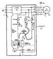
- FIG. 2 illustrates a circuit implementing a preferred embodiment of the invention.
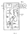
- FIG. 3 illustrates a circuit implementing a further preferred embodiment of the invention.
- FIG. 4 illustrates the voltage vectors of a zigzag transformer.
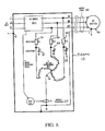
- FIG. 5 illustrates an embodiment implementing the invention with a wye-delta transformer.
- FIG. 6 illustrates a circuit for implementing the invention utilizing resistors in place of the transformer.
- FIG. 7 illustrates a circuit for implementing the invention utilizing inductors in place of the transformer.
- FIG. 8 illustrates an implementation of the invention utilizing direct grounding.
- FIG. 9 illustrates a method for implementing the invention.
- FIG. 10 illustrates a preferred embodiment of the method for implementing the invention.
- FIG. 2 illustrates a preferred embodiment of the invention. The neutral deriving network comprises a transformer T 1 (80) and series resistors R1-R3 (51-53), creating an artificial neutral point (70) from the three outputs (21, 22, 23) of the AC drive (20). The derived neutral point (70) is stable, and is not load bearing.
- A grounding resistor RG ( 60) is connected between the derived neutral point (70) and the system ground. Grounding resistor RG limits the current which flows to ground in the event of a short-circuit from any of the three AC drive output phases to ground. The resistance used for grounding resistor RG is application dependent, and has the objective of limiting the ground fault current to levels which are acceptable to a certain application and industry. For example, in the mining industry, there are applications which allow for a maximum current of 10 amperes, others that are limited to 0.5 amperes, and yet other, more stringent applications which allow for a maximum current of 125 milliamperes.
- Any ground fault current is detected by a ground fault voltage relay (GFVR 61) and/or a ground fault current relay (GFCR 63) and the drive is turned off without a catastrophic ground fault current surge occurring. The frame (10) and AC motor (40) are also grounded.
- The function of the transformer T 1 is to create or derive a neutral point (70) from a three-wire or delta-connected three-phase system. This is a fairly common way to come up with a neutral point of a symmetrical multiphase voltage source with no neutral point at the source.
- The resistors R 1-R3, in series with the windings of transformer T1, protect the transformer T1 and the AC drive (20) when the three-phase output of the AC drive goes below the operating frequency for which the transformer was designed. This prevents the outputs of the AC drive from shorting to one another via the transformer windings, since the core of the transformer saturates at frequencies below the rated operating frequency. Resistors R1-R3 also limit the current through the grounding resistor RG.
- The impedance of the transformer winding depends on its inductance and the frequency of the current flowing through it, or:
- Z=2*π*f*L
- where: “Z” is the transformer winding impedance; π is 3.14159 . . . ; “f” is the current frequency; “L” is the transformer winding inductance.
- The output frequency of the AC drive varies from zero (DC) to 60 hz or more. The transformer being submitted to this variable frequency will saturate, or loose its impedance, as the frequency goes below its rated value. In other words, at DC:
- Z=zero because f=zero.
- If only the transformer T 1 (without resistors R1-R3) is connected to the AC drive outputs, when its windings' impedance goes down to zero, the outputs will be shorted. Accordingly, since the impedance of the resistors R1-R3 does not change with frequency, as happens with the transformer winding, the resistors R1-R3 provide a minimum impedance when the AC drive output frequency is approaches zero Hertz.
- The resistance values of R 1-R3 are calculated so that when a phase short-circuit to ground occurs, the current through the transformer and through the grounding resistor is limited to a maximum value desired. Preferably, a minimum resistance of resistors R1-R3 is the resistance necessary to limit the current through transformer T1, to the lower of (a) the maximum current the conductors used as windings in the transformer can withstand (e.g., maximum current before the conductors fail), and (b) the maximum current the output of the AC drive can withstand (e.g.,, maximum overload current before AC drive fails), if the transformer saturates.
- As an alternative to resistors R 1-R3, an equivalent resistance can be embedded into the transformer by winding the transformer with wire of the right size and resistance (e.g., embedding magnetic wire ohmic resistance into the T1 windings).
- As with the motor cable ( 30), the PWM voltages output by the AC drive (20) cause common-mode currents to flow into the transformer T1 (80) because of coupling capacitances between its windings and the ground potential. These currents are filtered, or effectively filtered, by capacitors C1-C3 (81-83), which bypass the common-mode currents generated in the neutral deriving network to ground, while not affecting the ground fault current which has the same frequency as the motor current. Capacitors C1-C3 have small capacitance value and thus prevent any lags or distortion of the ground fault currents.
- Capacitors C 1-C3 are much smaller than the bypass capacitor used with the Neutral Point Inverter topology. The problem of accounting for bypassed current experienced with Neutral Point Inverter topology does not occur, because capacitor C1-C3 tune to the low-frequency zero-sequence components of the fault current, and because the impedance of the transformer rejects the high frequency components.
- With the derived neutral point, whenever a phase-to-ground short circuit happens, zero sequence currents flow between the neutral point and ground. Because these currents are all in-phase, they add up. Because the RLC circuit (i.e., resistors R 1-R3, transformer T1, capacitors C1-C3) filters the common mode currents that result from the pulsating nature of the AC drive output during normal operation, it allows the ground fault sensors to better differentiate between those currents and the zero sequence currents that happen during a phase short circuit to ground. Ground fault sensing can be either current-based (i.e.,
GFCR 63 and Transducer 64) or voltage-based (i.e.,GFVR 61 and Transducer 62), but preferably both types of sensors are included as it provides better redundancy. - The current transducer T 2 (64) and a GFCR (63) detect ground fault currents passing from the neutral point (70) to ground. When a current in excess to a set maximum threshold level passes through transducer T2, the GFCR will trip out, opening a normally open relay contact, thereby signaling to a control circuit that a ground fault has occurred. Although the GFCR can be normally open or normally closed, and can signal by either opening or closing, opening an normally open relay contact is the preferred configuration, since the GFCR will likely trip out in case of relay failure.
- The transducer T 2 should be able to detect pulsating DC and regular sine wave current, and should be able to couple DC currents without saturating. Because AC drives have a variable-frequency output voltage and current, the ground fault sensors used to monitor current and voltage can not saturate when the frequency is below 60 Hz, down to 0 Hz or DC. Some sensors are suitable for 50/60 Hz operation and may go down to 40 Hz, but ground fault sensors used with the present invention should be able to sense DC or 0 Hz signals as well as AC signals in order to monitor the AC drive outputs. Accordingly, transducer T2 should be able to sense DC or 0 Hz signals as well as AC signals in order to monitor the AC drive outputs. SMC's Relay SGF-25DC1 meets these requirements, and any equivalent relay may be used.
- A potential transducer T 3 (62) and a GFVR (61) detect ground faults based upon the voltage across the grounding resistor RG (60). When a voltage drop across the neutral grounding resistor RG exceeds a set maximum threshold voltage level, the drop is sensed through transducer T3. The GFVR will trip out, opening a normally open relay contact, thereby signaling to a control circuit that a ground fault has occurred. Although the GFVR can be normally open or normally closed, and can signal by either opening or closing, opening an normally open relay contact is the preferred configuration, since the GFVR will likely trip out in case of relay failure.
- The transducer T 3 should be able to detect pulsating DC voltage and sine wave voltages, and should be able to transform DC voltages without saturating. As discussed with regard to transducer T2, transducer T3 should be able to sense DC or 0 Hz voltage signals as well as AC signals in order to monitor the AC drive outputs.
- When dealing AC drives, and in particular with medium- and high-voltage AC drives, the voltage levels may reach thousands of volts. Therefore, for reliable operation of the electronics controls, a potential transducer that can safely monitor those levels is required, providing electrical isolation from the high voltage source of the monitored signal.
- Moreover, the potential transducer needs to be capable of monitoring variable frequency AC and DC voltages and have a reasonably fast dynamic response to the transients of the monitored voltage. A GFVR capable such variable frequency voltage signals and providing suitable isolation is SMC's Relay SGF-25DV1, and any equivalent device may be used.
- Normally, such transducer will produce a small isolated output signal when the monitored voltage reaches a maximum set value. For example, when the monitored voltage is at 4000V AC, the transducer output will read 4V AC. The best voltage transducers nowadays are magnetically coupled and use hall effect devices.
- Both of the ground fault relays ( 61, 63) utilize motor speed information “N” from the AC drive (20) in order to adapt to the variable output voltage. The motor speed information “N” is a signal available from most AC drive control circuits and is usually an isolated voltage signal or a discrete threshold-driven contact closures signal. The signal “N” simply reflects the actual motor shaft speed or the AC drive output frequency.
- Motor shaft speed is directly related to the frequency of the applied voltage. AC drives vary the motor shaft speed by modifying the frequency and the amplitude of the three-phase output voltage. The torque of a motor can be defined as a ratio of volts per hertz, i.e., to maintain the motor torque constant the volts/hertz ratio has to be kept constant. For example, a 480V 60 Hz motor requires a 480V/60 Hz or 8V/Hz ratio in order to keep its magnetic flux constant, without saturation (larger V/Hz ratio) or starving (low V/Hz ratio). This means that when “N” changes the voltage amplitude also changes proportionally.
- Because speed and voltage are changing in order to change the operating speed of an AC motor, the common-mode currents change and are inversely proportional to “N”. More importantly, the ground fault current changes directly proportional to “N” because of the corresponding voltage change, or by Ohm's Law:
- i=v /RG
- where “i” is the current through the grounding resistor, “v” is the ground to neutral voltage and is directly proportional to the output voltage, and “RG” is the grounding resistor value.
- The Ground Fault Current Relay ( 63) reads the “N” information and adapts the fault current threshold level accordingly. As the drive output voltage increases, so does the fault current threshold. Similarly, the Ground Fault Voltage Relay (61) reads the “N” information and adapts the fault voltage threshold level accordingly. As the drive output voltage increases, so does the fault voltage threshold.
- For further background of ground fault relays, illustrating the state of the art, see U.S. Pat. No. 6,327,124, published Dec. 4, 2001, which is incorporated herein by reference.
- A further preferred embodiment is illustrated in FIG. 3, which is the same as the embodiment in FIG. 2 as discussed above, except that the decoupling capacitors C 1-C3 are embedded in transformer T1′ (90). Placing the decoupling capacitors within transformer T1′ is advantageous for minimizing component count and size. Embedding the capacitance is accomplished by selectively including a dielectric material between the windings of the transformer and a grounded plate or foil within the transformer. Preferably, the dielectric is a coating applied to a respective winding, and the grounded plate or foil is foil shielding that winding.
- In FIGS. 2 and 3, the neutral deriving network uses a zigzag transformer. The zigzag transformer is preferred, as its use is widely accepted in industry, and in particular, by the regulatory agencies that rule on grounding and electrical hazard safety. Also, if the embodiment of FIG. 3 is used, the filter capacitance C 1-C3 can be easily integrated into the construction of the zigzag transformer.
- Moreover, looking at FIG. 4, the dashed arrows are the resulting voltage vectors of a zigzag transformer. As shown, the voltage vectors are balanced and phase shifted by 120 degrees. Because each vector is the sum of the voltage of two different windings, whatever happens to one winding ends up affecting the resultant voltage vectors of the other phases. This happens because of the magnetic cross coupling within zigzag transformers. Windings a and a′ are in phase because they are wound in the same leg of the transformer. The same is true for b and b′, and c and c′. This advantageously allows the zigzag transformer to regulate the neutral potential and therefore allow neutral currents to be drawn, without causing voltage imbalance, up to the designed rating of the transformer.
- However, there are other ways to derive the neutral point. Another choice is a wye-delta transformer. As illustrated in FIG. 5, the wye-delta transformer ( 91) also provides a neutral point (73). Wye-delta transformers are also widely accepted in industry for deriving a neutral point out of a delta-connected three-phase system, and in this regard, function in the same way as a zigzag transformers.
- Generally speaking, zigzag transformers are designed specifically targeting the generation and regulation of a neutral point. In comparison, wye-delta transformers are generally designed for supplying power to a certain rating and therefore may not be exactly suitable for certain neutral generating applications. Also, as typically constructed, wye-delta transformers have a higher impedance to zero-impedance currents than zigzag transformers. However, the neutral potential regulating effect of a wye-delta transformer is the same as that of the zigzag's, as explained above.
- As in the discussion of zig-zag transformers, capacitance C 1-C3 can be integrated into the wye-delta transformer (not illustrated). In such a case, it is preferable that at least the three windings tied to the neutral point (i.e., the windings forming the “wye”) be provided with capacitance.
- An artificial neutral point can also be derived without using a transformer. For example, by using either three inductors or three resistors as a substitute for the transformer. A resistor-based substitute is shown in FIG. 6, in which resistors R 4-R6 (54-56) provide a neutral point (71). Each branch of the network has two resistors, creating a point for connecting capacitors C1-C3, and dividing the dissipated power between two resistors. Each resistor provides half the resistance per branch, although this proportion is not required, and some variation on the proportion between the two resistors will also work. A similar inductor-based solution is shown in FIG. 7, in which inductors L1-L3 (101-103) provide a neutral point (72).
- The purely resistive or inductive network solutions do allow the creation of a neutral point for reference, and do suffice to reduce the ground fault currents in case of a short to ground, but do not provide regulation of the neutral potential. During normal operation, the AC drive circuit will keep the three-phase output voltages in balance, such that it does not require a transformer to regulate the neutral potential. However, under fault conditions, using a purely resistive or inductive network, the neutral point will become unstable as the neutral shifts due to the voltage imbalance.
- As a further embodiment of the invention, direct grounding can also be used, as exemplified in FIG. 8. The neutral point ( 74) is tied to ground by a conductor, and the GFCR and current transducer (63) is used to detect the ground fault current passing through the neutral point. In this case, resistors R1-R3 are responsible for limiting the current which flows to ground in the event of a short-circuit, in addition to protecting the AC drive (20) and the transformer during saturation. Although a zig-zag transformer (80) is illustrated, direct grounding can be utilized with the other neutral point deriving circuits.
- When a transformer is utilized with the invention, it is preferably “inverter duty.” As stated above, the AC drive output voltage is formed of pulses with variable duration which passing through an inductive load, produces a quasi-sinusoidal current. While the input utility voltage is sinusoidal and therefore has negligible dV/dt—less than 5V per microsecond in a 4,160V line—the AC drive output voltages have very fast edges and can cause reflected wave phenomena on the motor cables which end up causing a voltage increase by superposition of the reflected voltage waves, submitting the transformer or motor windings to higher voltages than their name plate voltages.
- Common winding techniques used for purely sine wave voltage applications will not suffice for reliable operation with AC drives. There are various techniques that improve the reliability of transformers and motors windings which involve both how they are physically wound as well as the type and amount of insulation used. Transformers designed to withstand the rigors of inverter output voltage waveforms are referred to as “inverter duty.” Winding and insulation techniques are used to minimize the corona effect damages, which may occur.
- The corona effect is related to the ionization of gas particles around a conductor with high electrical potential. It causes the deterioration of the insulation materials whether they be the magnetic wire insulation material or the insulation in between windings. Another side effect of the corona effect is the smell of ozone gas in its proximity. The techniques for preventing corona damage are common knowledge of those who are skilled in the art, and are therefore omitted here. But for these reasons, an inverter duty transformer should be utilized.
- Based on the above embodiments, the invention can also be expressed as a method. Referring to FIG. 9, the method comprises deriving the neutral point from the three-phase output of the AC drive ( 201), individually decoupling the normal operating currents of each phase of the three-phase output from the neutral point (202), grounding the neutral point (203), detecting a ground fault in the AC drive by sensing when signals between the neutral point and ground exceed a maximum threshold level (204), adjusting the maximum threshold level indicating ground fault based on a rotational speed of a motor driven by the AC drive (205); and signaling when a ground fault has been detected.
- As a further expression of a method of performing the invention, FIG. 10 illustrates a method for performing a preferred embodiment using a transformer to derive the neutral point. The method comprises selecting resistance to provide to the transformer to limit current to no more than the maximum current the transformer and AC drive can withstand when the transformer saturates ( 301); providing that resistance, either internally or externally, to the transformer, thereby limiting the current levels during saturation (302); connecting the windings of the transformer to the output of the AC drive (303); grounding the neutral terminal of the transformer via a grounding resistor (304); determining capacitance for each capacitive path used to decouple the normal operating currents of the AC drive so that there is no distortion or lag in zero-sequence signals during a ground fault (305); individually decoupling the normal operating currents of each phase of the AC drive output from the neutral point by individually filtering signals of each phase of the three-phase output prior to the signals reaching the neutral point by providing the capacitive paths bypassing the neutral point to ground for the normal operating current (306); determining a rotational speed of a motor drive by the AC drive (307); adjusting a maximum threshold current level based upon the rotational speed of the motor(308); adjusting a maximum threshold voltage level based upon the rotational speed of the motor(309); detecting a ground fault by sensing when current from passing from the neutral point to ground exceeds the maximum current threshold level (310); detecting a ground fault by sensing when the voltage drop across the grounding resistor exceeds the maximum voltage threshold level (311); and signaling that a ground fault has occurred by switching, either open or closed, a relay contact (312).
- In summation, the present invention provides enhanced ground-fault protection to AC motor drive systems. Unlike the DC Link Neutral Point approach, the invention is able to be applied to any drive-to-motor cable length without the need for further tuning. The invention makes this possible because it decouples the common-mode currents generated by the inverter output due to the PWM voltage pulses, which are in phase in all of the three outputs. The sub-harmonic content, though are phase shifted by 120 degrees like in any three-phase system. The invention works equally well with any three-phase drive system.
- It is to be understood that the above-described embodiments and implementations are only illustrative of an application of the principles of the invention. Alternative arrangements are possible.
- In addition to embedding at least some of the resistance in the transformer, or embedding the capacitance in the transformer, both the resistance (i.e., R 1-R3) and capacitance (i.e., C1-C3) can be embedded into the transformer. Also, instead of using a speed reference signal “N” output from the AC drive, the ground fault relays can utilize rotational speed information determined by monitoring the motor. Also, instead of adaptively adjusting threshold sensitivity based on motor speed, a predetermined threshold can be used; however in such a case, greater demands are placed on the Ground Fault Relay for noise immunity and resistance to nuisance tripping.
- Accordingly, it is contemplated that numerous modifications may be made to the embodiments and implementations of the present invention without departing from the spirit and scope of the invention as defined in the following claims.
Claims (27)
Priority Applications (1)
| Application Number | Priority Date | Filing Date | Title |
|---|---|---|---|
| US10/404,646 US7050279B2 (en) | 2002-04-05 | 2003-04-02 | Method and apparatus for high impedance grounding of medium voltage AC drives |
Applications Claiming Priority (2)
| Application Number | Priority Date | Filing Date | Title |
|---|---|---|---|
| US36987202P | 2002-04-05 | 2002-04-05 | |
| US10/404,646 US7050279B2 (en) | 2002-04-05 | 2003-04-02 | Method and apparatus for high impedance grounding of medium voltage AC drives |
Publications (2)
| Publication Number | Publication Date |
|---|---|
| US20030197989A1 true US20030197989A1 (en) | 2003-10-23 |
| US7050279B2 US7050279B2 (en) | 2006-05-23 |
Family
ID=29218875
Family Applications (1)
| Application Number | Title | Priority Date | Filing Date |
|---|---|---|---|
| US10/404,646 Active - Reinstated 2024-09-17 US7050279B2 (en) | 2002-04-05 | 2003-04-02 | Method and apparatus for high impedance grounding of medium voltage AC drives |
Country Status (1)
| Country | Link |
|---|---|
| US (1) | US7050279B2 (en) |
Cited By (31)
| Publication number | Priority date | Publication date | Assignee | Title |
|---|---|---|---|---|
| US20050189903A1 (en) * | 2004-03-01 | 2005-09-01 | Rexon Industrial Corp., Ltd. | Apparatus for controlling a variable speed motor of a combined belt and disk sander |
| GB2417568A (en) * | 2004-08-28 | 2006-03-01 | Siemens Ag | Method of measuring motor supply line capacitance in AC drives |
| WO2006108535A1 (en) * | 2005-04-13 | 2006-10-19 | Ab Skf | Assembly comprising a three-phase machine and a frequency converter |
| US20080007197A1 (en) * | 2006-06-26 | 2008-01-10 | Hitachi, Ltd. | Inverter-driven rotating machine system, rotating machine and inverter used in the same and electric vehicle using the same |
| US20080088466A1 (en) * | 2006-10-16 | 2008-04-17 | Schweitzer Engineering Laboratories, Inc. | System and method to zero-sequence verify ground return path integrity by comparing measured zero-sequence current in an autotransformer with a second zero-sequence current source |
| US20080211683A1 (en) * | 2007-03-01 | 2008-09-04 | Power Monitors | Method and apparatus for loose wiring monitor |
| EP1966812A1 (en) * | 2005-12-30 | 2008-09-10 | Smc Electrical Products, Inc. | Variable frequency drive system apparatus and method for reduced ground leakage current and transistor protection |
| US20110148391A1 (en) * | 2009-12-18 | 2011-06-23 | Rosendin Electric, Inc. | Various methods and apparatuses for an integrated zig-zag transformer |
| US20130044522A1 (en) * | 2011-08-17 | 2013-02-21 | Honeywell International Inc. | Low weight 3-phase 5-output wire power conversion system for micro-grid |
| US20130077194A1 (en) * | 2011-09-23 | 2013-03-28 | GM Global Technology Operations LLC | Protection of motor drive systems from current sensor faults |
| US20130257334A1 (en) * | 2012-03-28 | 2013-10-03 | Joy Mm Delaware, Inc. | Ground fault detection methods on variable frequency drive systems |
| US20140014411A1 (en) * | 2012-07-13 | 2014-01-16 | Associated Power Technologies, Inc. | Electrical instrument having configurable input terminal block |
| DE102011082554B4 (en) * | 2011-09-12 | 2014-04-10 | H. Kleinknecht Gmbh & Co. Kg | Method for determining an earth fault current in a three-phase system subject to earth faults |
| US8773108B2 (en) | 2009-11-10 | 2014-07-08 | Power Monitors, Inc. | System, method, and apparatus for a safe powerline communications instrumentation front-end |
| US8775109B2 (en) | 2010-07-29 | 2014-07-08 | Power Monitors, Inc. | Method and apparatus for a demand management monitoring system |
| US20140217819A1 (en) * | 2013-02-06 | 2014-08-07 | Siemens Aktiengesellschaft | Arrangement for Igniting Thin Rods Composed of Electrically Conductive Material, in Particular Thin Silicon Rods |
| US20140320148A1 (en) * | 2013-04-30 | 2014-10-30 | Eaton Corporation | System and method for detecting excess voltage drop in three-phase ac circuits |
| US20140327346A1 (en) * | 2013-05-02 | 2014-11-06 | Ge Energy Power Conversion Technology Limited | Multi-phase electric circuit |
| US20150091582A1 (en) * | 2013-10-01 | 2015-04-02 | Rockwell Automation Technologies, Inc. | Hrg ground fault detector and method |
| US20150130379A1 (en) * | 2012-04-09 | 2015-05-14 | Toshiba Mitsubishi-Electric Industrial Systems Corporation | Ground fault detecting circuit and power converting device including the same |
| WO2015145069A1 (en) | 2014-03-26 | 2015-10-01 | Hossein Borojeni | Connection cable forming a protective cover |
| US9202383B2 (en) | 2008-03-04 | 2015-12-01 | Power Monitors, Inc. | Method and apparatus for a voice-prompted electrical hookup |
| US20170012423A1 (en) * | 2014-02-21 | 2017-01-12 | The Uab Research Foundation | Method for detecting an open-phase condition of a transformer |
| US9595825B2 (en) | 2007-01-09 | 2017-03-14 | Power Monitors, Inc. | Method and apparatus for smart circuit breaker |
| JP2018068009A (en) * | 2016-10-18 | 2018-04-26 | 株式会社日立製作所 | Electric motor power system and electric vehicle |
| US10060957B2 (en) | 2010-07-29 | 2018-08-28 | Power Monitors, Inc. | Method and apparatus for a cloud-based power quality monitor |
| US20190204374A1 (en) * | 2018-01-04 | 2019-07-04 | Rockwell Automation Technologies, Inc. | Automatic system grounding condition detection |
| CN111614376A (en) * | 2020-03-05 | 2020-09-01 | 国网青海省电力公司果洛供电公司 | Medium voltage power line impedance test system based on medium voltage carrier communication device |
| US11056883B1 (en) * | 2019-12-18 | 2021-07-06 | Switched Source Pb Llc | System and method for implementing a zero-sequence current filter for a three-phase power system |
| US20210359507A1 (en) * | 2020-05-18 | 2021-11-18 | Littelfuse, Inc. | Ground fault protection circuit and techniques |
| US11296509B1 (en) | 2021-05-03 | 2022-04-05 | Switched Source PB, LLC | Zero-sequence current balancer with a real power injector for a three-phase power system |
Families Citing this family (11)
| Publication number | Priority date | Publication date | Assignee | Title |
|---|---|---|---|---|
| US7498819B2 (en) * | 2006-03-21 | 2009-03-03 | General Electric Company | Method, apparatus and computer-readable code for detecting an incipient ground fault in an electrical propulsion system |
| US7501830B2 (en) * | 2006-03-21 | 2009-03-10 | General Electric Company | Method, apparatus and computer-readable code for detecting an incipient ground fault in an electrical propulsion system |
| US7498820B2 (en) * | 2006-03-21 | 2009-03-03 | General Electric Company | Method, apparatus and computer-readable code for detecting an incipient ground fault in an electrical propulsion system |
| US7969696B2 (en) * | 2007-12-06 | 2011-06-28 | Honeywell International Inc. | Ground fault detection and localization in an ungrounded or floating DC electrical system |
| US7848122B2 (en) * | 2008-04-23 | 2010-12-07 | Rockwell Automation Technologies, Inc. | Terminator for reducing differential-mode and common-mode voltage reflections in AC motor drives |
| ITLU20080013A1 (en) * | 2008-08-14 | 2008-11-13 | Giovanni Pieri | SAFETY SYSTEM FOR ELECTRICITY SUPPLY TO SINGLE OR MULTIPLE LIVING UNITS (PARTICULARLY PART OF MULTI-STOREY BUILDINGS), TO AVOID THAT HAZARDOUS CONTACT VOLTAGES CAN BE HAVING ON THE GENERAL NODE |
| US20100217546A1 (en) * | 2009-02-20 | 2010-08-26 | Anthony Locker | Methods and Apparatuses for Detecting Faults in Electrical Power Systems |
| EP2372022B1 (en) * | 2010-03-23 | 2014-12-31 | Joseph Vögele AG | Street construction machine |
| US8710850B2 (en) * | 2010-12-27 | 2014-04-29 | Renault S.A.S. | System and method for detecting an earth ground fault of an external power supply connected to a vehicle |
| US8827017B2 (en) | 2012-03-30 | 2014-09-09 | Thermo King Corporation | Vehicle or environment-controlled unit having a multiphase alternator with a protected high-voltage bus |
| US10411624B2 (en) | 2017-08-31 | 2019-09-10 | Abb Schweiz Ag | Switching transient damper method and apparatus |
Citations (4)
| Publication number | Priority date | Publication date | Assignee | Title |
|---|---|---|---|---|
| US3477010A (en) * | 1967-04-11 | 1969-11-04 | Lear Jet Ind Inc | Synthetic wave three phase alternating current power supply system |
| US4542432A (en) * | 1982-08-27 | 1985-09-17 | Square D Company | Ground fault detection circuit |
| US6421594B1 (en) * | 1999-03-18 | 2002-07-16 | Joseph Vogele Ag | Method for heating the paving screed of a road finisher and electrical heating means |
| US6888708B2 (en) * | 2001-06-20 | 2005-05-03 | Post Glover Resistors, Inc. | Method and apparatus for control and detection in resistance grounded electrical systems |
Family Cites Families (8)
| Publication number | Priority date | Publication date | Assignee | Title |
|---|---|---|---|---|
| US5574356A (en) | 1994-07-08 | 1996-11-12 | Northrop Grumman Corporation | Active neutral current compensator |
| US5576942A (en) | 1994-09-30 | 1996-11-19 | Universities Research Association, Inc. | Method and apparatus for reducing the harmonic currents in alternating-current distribution networks |
| CA2157307C (en) | 1994-10-10 | 1999-07-06 | Luke Yu | Zero-sequence current suppressor |
| US5656924A (en) | 1995-09-27 | 1997-08-12 | Schott Power Systems Inc. | System and method for providing harmonic currents to a harmonic generating load connected to a power system |
| US6028405A (en) | 1998-01-14 | 2000-02-22 | Yaskawa Electric America, Inc. | Variable frequency drive noise attenuation circuit |
| US6208098B1 (en) | 1998-03-02 | 2001-03-27 | Yaskawa Electric America, Inc. | Variable frequency drive noise attenuation circuit |
| US6154378A (en) | 1998-04-29 | 2000-11-28 | Lockheed Martin Corporation | Polyphase inverter with neutral-leg inductor |
| US6327124B1 (en) | 1999-02-05 | 2001-12-04 | Smc Electrical Products, Inc. | Low current ground fault relay |
-
2003
- 2003-04-02 US US10/404,646 patent/US7050279B2/en active Active - Reinstated
Patent Citations (4)
| Publication number | Priority date | Publication date | Assignee | Title |
|---|---|---|---|---|
| US3477010A (en) * | 1967-04-11 | 1969-11-04 | Lear Jet Ind Inc | Synthetic wave three phase alternating current power supply system |
| US4542432A (en) * | 1982-08-27 | 1985-09-17 | Square D Company | Ground fault detection circuit |
| US6421594B1 (en) * | 1999-03-18 | 2002-07-16 | Joseph Vogele Ag | Method for heating the paving screed of a road finisher and electrical heating means |
| US6888708B2 (en) * | 2001-06-20 | 2005-05-03 | Post Glover Resistors, Inc. | Method and apparatus for control and detection in resistance grounded electrical systems |
Cited By (59)
| Publication number | Priority date | Publication date | Assignee | Title |
|---|---|---|---|---|
| US20050189903A1 (en) * | 2004-03-01 | 2005-09-01 | Rexon Industrial Corp., Ltd. | Apparatus for controlling a variable speed motor of a combined belt and disk sander |
| GB2417568A (en) * | 2004-08-28 | 2006-03-01 | Siemens Ag | Method of measuring motor supply line capacitance in AC drives |
| US20090039816A1 (en) * | 2005-04-13 | 2009-02-12 | Ab Skf | Assembly Comprising a Three-Phase Machine and a Frequency Converter |
| WO2006108535A1 (en) * | 2005-04-13 | 2006-10-19 | Ab Skf | Assembly comprising a three-phase machine and a frequency converter |
| US7948206B2 (en) * | 2005-04-13 | 2011-05-24 | Ab Skf | Assembly comprising a three-phase machine and a frequency converter |
| EP1966812A4 (en) * | 2005-12-30 | 2010-11-03 | Smc Electrical Products Inc | Variable frequency drive system apparatus and method for reduced ground leakage current and transistor protection |
| EP1966812A1 (en) * | 2005-12-30 | 2008-09-10 | Smc Electrical Products, Inc. | Variable frequency drive system apparatus and method for reduced ground leakage current and transistor protection |
| US7764042B2 (en) * | 2006-06-26 | 2010-07-27 | Hitachi, Ltd. | Inverter-driven rotating machine system, rotating machine and inverter used in the same and electric vehicle using the same |
| US20080007197A1 (en) * | 2006-06-26 | 2008-01-10 | Hitachi, Ltd. | Inverter-driven rotating machine system, rotating machine and inverter used in the same and electric vehicle using the same |
| US7940054B2 (en) * | 2006-10-16 | 2011-05-10 | Schweitzer Engineering Laboratories, Inc. | System and method to zero-sequence verify ground return path integrity by comparing measured zero-sequence current in an autotransformer with a second zero-sequence current source |
| US20080088466A1 (en) * | 2006-10-16 | 2008-04-17 | Schweitzer Engineering Laboratories, Inc. | System and method to zero-sequence verify ground return path integrity by comparing measured zero-sequence current in an autotransformer with a second zero-sequence current source |
| US9595825B2 (en) | 2007-01-09 | 2017-03-14 | Power Monitors, Inc. | Method and apparatus for smart circuit breaker |
| US20080211683A1 (en) * | 2007-03-01 | 2008-09-04 | Power Monitors | Method and apparatus for loose wiring monitor |
| US8125345B2 (en) * | 2007-03-01 | 2012-02-28 | Power Monitors | Method and apparatus for loose wiring monitor |
| US9202383B2 (en) | 2008-03-04 | 2015-12-01 | Power Monitors, Inc. | Method and apparatus for a voice-prompted electrical hookup |
| US8773108B2 (en) | 2009-11-10 | 2014-07-08 | Power Monitors, Inc. | System, method, and apparatus for a safe powerline communications instrumentation front-end |
| US9404943B2 (en) | 2009-11-10 | 2016-08-02 | Power Monitors, Inc. | System, method, and apparatus for a safe powerline communications instrumentation front-end |
| US20110148391A1 (en) * | 2009-12-18 | 2011-06-23 | Rosendin Electric, Inc. | Various methods and apparatuses for an integrated zig-zag transformer |
| US8384371B2 (en) * | 2009-12-18 | 2013-02-26 | Rosendin Electric, Inc. | Various methods and apparatuses for an integrated zig-zag transformer |
| US8775109B2 (en) | 2010-07-29 | 2014-07-08 | Power Monitors, Inc. | Method and apparatus for a demand management monitoring system |
| US9519559B2 (en) | 2010-07-29 | 2016-12-13 | Power Monitors, Inc. | Method and apparatus for a demand management monitoring system |
| US10060957B2 (en) | 2010-07-29 | 2018-08-28 | Power Monitors, Inc. | Method and apparatus for a cloud-based power quality monitor |
| US20130044522A1 (en) * | 2011-08-17 | 2013-02-21 | Honeywell International Inc. | Low weight 3-phase 5-output wire power conversion system for micro-grid |
| US8964423B2 (en) * | 2011-08-17 | 2015-02-24 | Honeywell International Inc. | Low weight 3-phase 5-output wire power conversion system for micro-grid |
| DE102011082554B4 (en) * | 2011-09-12 | 2014-04-10 | H. Kleinknecht Gmbh & Co. Kg | Method for determining an earth fault current in a three-phase system subject to earth faults |
| US8867181B2 (en) * | 2011-09-23 | 2014-10-21 | GM Global Technology Operations LLC | Protection of motor drive systems from current sensor faults |
| US20130077194A1 (en) * | 2011-09-23 | 2013-03-28 | GM Global Technology Operations LLC | Protection of motor drive systems from current sensor faults |
| US11329589B2 (en) * | 2012-03-28 | 2022-05-10 | Joy Global Underground Mining Llc | Ground fault detection methods on variable frequency drive systems |
| CN103424696A (en) * | 2012-03-28 | 2013-12-04 | 乔伊·姆·特拉华公司 | Ground fault detection methods on variable frequency drive systems |
| US20130257334A1 (en) * | 2012-03-28 | 2013-10-03 | Joy Mm Delaware, Inc. | Ground fault detection methods on variable frequency drive systems |
| US9606163B2 (en) * | 2012-04-09 | 2017-03-28 | Toshiba Mitsubishi-Electric Industrial Systems Corporation | Ground fault detecting circuit and power converting device including the same |
| US20150130379A1 (en) * | 2012-04-09 | 2015-05-14 | Toshiba Mitsubishi-Electric Industrial Systems Corporation | Ground fault detecting circuit and power converting device including the same |
| US20140014411A1 (en) * | 2012-07-13 | 2014-01-16 | Associated Power Technologies, Inc. | Electrical instrument having configurable input terminal block |
| US8908354B2 (en) * | 2012-07-13 | 2014-12-09 | Associated Research Technologies, Inc. | Electrical instrument having configurable input terminal block |
| US20140217819A1 (en) * | 2013-02-06 | 2014-08-07 | Siemens Aktiengesellschaft | Arrangement for Igniting Thin Rods Composed of Electrically Conductive Material, in Particular Thin Silicon Rods |
| US9698698B2 (en) * | 2013-02-06 | 2017-07-04 | Siemens Aktiengesellschaft | Arrangement for igniting thin rods composed of electrically conductive material, in particular thin silicon rods |
| US8963556B2 (en) * | 2013-04-30 | 2015-02-24 | Eaton Corporation | System and method for detecting excess voltage drop in three-phase AC circuits |
| US20140320148A1 (en) * | 2013-04-30 | 2014-10-30 | Eaton Corporation | System and method for detecting excess voltage drop in three-phase ac circuits |
| US9543812B2 (en) * | 2013-05-02 | 2017-01-10 | Ge Energy Power Conversion Technology Limited | Multi-phase electric circuit |
| US20140327346A1 (en) * | 2013-05-02 | 2014-11-06 | Ge Energy Power Conversion Technology Limited | Multi-phase electric circuit |
| US9383399B2 (en) * | 2013-10-01 | 2016-07-05 | Rockwell Automation Technologies, Inc. | HRG ground fault detector and method using phase inputs to generate a simulated neutral voltage |
| US20150091582A1 (en) * | 2013-10-01 | 2015-04-02 | Rockwell Automation Technologies, Inc. | Hrg ground fault detector and method |
| EP2857850A1 (en) * | 2013-10-01 | 2015-04-08 | Rockwell Automation Technologies, Inc. | HRG ground fault detector and method |
| CN104515927A (en) * | 2013-10-01 | 2015-04-15 | 洛克威尔自动控制技术股份有限公司 | HRG ground fault detector and method |
| US10931094B2 (en) | 2014-02-21 | 2021-02-23 | The Uab Research Foundation | Method for detecting an open-phase condition of a transformer |
| US20170012423A1 (en) * | 2014-02-21 | 2017-01-12 | The Uab Research Foundation | Method for detecting an open-phase condition of a transformer |
| US10090665B2 (en) * | 2014-02-21 | 2018-10-02 | The Uab Research Foundation | Method for detecting an open-phase condition of a transformer |
| US10522998B2 (en) | 2014-02-21 | 2019-12-31 | The Uab Research Foundation | Method for detecting an open-phase condition of a transformer |
| WO2015145069A1 (en) | 2014-03-26 | 2015-10-01 | Hossein Borojeni | Connection cable forming a protective cover |
| FR3019369A1 (en) * | 2014-03-26 | 2015-10-02 | Hossein Borojeni | CONNECTION CABLE |
| JP2018068009A (en) * | 2016-10-18 | 2018-04-26 | 株式会社日立製作所 | Electric motor power system and electric vehicle |
| US20190204374A1 (en) * | 2018-01-04 | 2019-07-04 | Rockwell Automation Technologies, Inc. | Automatic system grounding condition detection |
| US10725116B2 (en) * | 2018-01-04 | 2020-07-28 | Rockwell Automation Technologies, Inc. | Automatic system grounding condition detection |
| US11056883B1 (en) * | 2019-12-18 | 2021-07-06 | Switched Source Pb Llc | System and method for implementing a zero-sequence current filter for a three-phase power system |
| CN111614376A (en) * | 2020-03-05 | 2020-09-01 | 国网青海省电力公司果洛供电公司 | Medium voltage power line impedance test system based on medium voltage carrier communication device |
| US20210359507A1 (en) * | 2020-05-18 | 2021-11-18 | Littelfuse, Inc. | Ground fault protection circuit and techniques |
| US11368014B2 (en) * | 2020-05-18 | 2022-06-21 | Littelfuse, Inc. | Ground fault protection circuit and techniques |
| US11296509B1 (en) | 2021-05-03 | 2022-04-05 | Switched Source PB, LLC | Zero-sequence current balancer with a real power injector for a three-phase power system |
| US11418034B1 (en) | 2021-05-03 | 2022-08-16 | Switched Source PB, LLC | Zero-sequence current balancer with a real power injector for a three-phase power system |
Also Published As
| Publication number | Publication date |
|---|---|
| US7050279B2 (en) | 2006-05-23 |
Similar Documents
| Publication | Publication Date | Title |
|---|---|---|
| US7050279B2 (en) | Method and apparatus for high impedance grounding of medium voltage AC drives | |
| Das et al. | Grounding of AC and DC low-voltage and medium-voltage drive systems | |
| JP2608552B2 (en) | Ground fault circuit breaker | |
| JP3763852B2 (en) | Method and circuit for monitoring insulation and fault current in AC power supply | |
| US8373952B2 (en) | Integrated DC link inductor and common mode current sensor winding | |
| US8704481B2 (en) | Choke with current sensor | |
| US6025980A (en) | Earth leakage protective relay | |
| US10985559B2 (en) | Method and system for improved operation of power grid components in the presence of direct current (DC) | |
| CN105914712A (en) | Device and method for detecting residual curent | |
| Styvaktakis et al. | Signatures of voltage dips: transformer saturation and multistage dips | |
| WO2015080828A2 (en) | Feeder power source providing open feeder detection for a network protector by shifted neutral | |
| CZ35296A3 (en) | Circuit arrangement of a stator ground connection for three-phase machines | |
| JPS61196718A (en) | Ground-fault protector | |
| EP0453196A2 (en) | Transformer differential relay | |
| US3944846A (en) | Subsynchronous relay | |
| JP3783173B2 (en) | AC / DC leakage detector | |
| JPH08237936A (en) | Noise filter for voltage type inverter | |
| CN112731200A (en) | Monitoring device for leakage current | |
| JPH07312823A (en) | Dc leak detection and protective device | |
| Skibinski et al. | Effect of adjustable speed drives on the operation of low voltage ground fault indicators | |
| JP3564211B2 (en) | Ground fault detection method and device | |
| CA1099341A (en) | Circuit arrangement for detecting grounds in a static converter | |
| JPH06237522A (en) | Protective device of series capacitor | |
| Osman | GROUNDING OF AC AND DC LOW VOLTAGE AND MEDIUM VOLTAGE DRIVE SYSTEMS | |
| JP3615170B2 (en) | Method for determining the application of DC voltage in an AC cable line, a method for removing the DC voltage, and a device for preventing an increase in potential of the AC cable line during a ground fault |
Legal Events
| Date | Code | Title | Description |
|---|---|---|---|
| AS | Assignment |
Owner name: SMC ELECTRICAL PRODUCTS INC., WEST VIRGINIA Free format text: ASSIGNMENT OF ASSIGNORS INTEREST;ASSIGNOR:NOJIMA, GERALDO;REEL/FRAME:013930/0843 Effective date: 20030401 |
|
| FEPP | Fee payment procedure |
Free format text: PETITION RELATED TO MAINTENANCE FEES GRANTED (ORIGINAL EVENT CODE: PMFG); ENTITY STATUS OF PATENT OWNER: LARGE ENTITY Free format text: PETITION RELATED TO MAINTENANCE FEES FILED (ORIGINAL EVENT CODE: PMFP); ENTITY STATUS OF PATENT OWNER: LARGE ENTITY |
|
| REMI | Maintenance fee reminder mailed | ||
| REIN | Reinstatement after maintenance fee payment confirmed | ||
| FP | Lapsed due to failure to pay maintenance fee |
Effective date: 20100523 |
|
| FPAY | Fee payment |
Year of fee payment: 4 |
|
| PRDP | Patent reinstated due to the acceptance of a late maintenance fee |
Effective date: 20101129 |
|
| STCF | Information on status: patent grant |
Free format text: PATENTED CASE |
|
| SULP | Surcharge for late payment | ||
| FEPP | Fee payment procedure |
Free format text: PAT HOLDER NO LONGER CLAIMS SMALL ENTITY STATUS, ENTITY STATUS SET TO UNDISCOUNTED (ORIGINAL EVENT CODE: STOL); ENTITY STATUS OF PATENT OWNER: LARGE ENTITY |
|
| REFU | Refund |
Free format text: REFUND - PAYMENT OF MAINTENANCE FEE, 8TH YR, SMALL ENTITY (ORIGINAL EVENT CODE: R2552); ENTITY STATUS OF PATENT OWNER: LARGE ENTITY |
|
| FPAY | Fee payment |
Year of fee payment: 8 |
|
| MAFP | Maintenance fee payment |
Free format text: PAYMENT OF MAINTENANCE FEE, 12TH YEAR, LARGE ENTITY (ORIGINAL EVENT CODE: M1553) Year of fee payment: 12 |