US20030197920A1 - Optical amplifying method - Google Patents
Optical amplifying method Download PDFInfo
- Publication number
- US20030197920A1 US20030197920A1 US10/445,944 US44594403A US2003197920A1 US 20030197920 A1 US20030197920 A1 US 20030197920A1 US 44594403 A US44594403 A US 44594403A US 2003197920 A1 US2003197920 A1 US 2003197920A1
- Authority
- US
- United States
- Prior art keywords
- signal light
- light
- output
- waveform
- amplified
- Prior art date
- Legal status (The legal status is an assumption and is not a legal conclusion. Google has not performed a legal analysis and makes no representation as to the accuracy of the status listed.)
- Granted
Links
Images


Classifications
-
- H—ELECTRICITY
- H01—ELECTRIC ELEMENTS
- H01S—DEVICES USING THE PROCESS OF LIGHT AMPLIFICATION BY STIMULATED EMISSION OF RADIATION [LASER] TO AMPLIFY OR GENERATE LIGHT; DEVICES USING STIMULATED EMISSION OF ELECTROMAGNETIC RADIATION IN WAVE RANGES OTHER THAN OPTICAL
- H01S3/00—Lasers, i.e. devices using stimulated emission of electromagnetic radiation in the infrared, visible or ultraviolet wave range
- H01S3/05—Construction or shape of optical resonators; Accommodation of active medium therein; Shape of active medium
- H01S3/06—Construction or shape of active medium
- H01S3/063—Waveguide lasers, i.e. whereby the dimensions of the waveguide are of the order of the light wavelength
- H01S3/067—Fibre lasers
- H01S3/06754—Fibre amplifiers
- H01S3/06758—Tandem amplifiers
-
- H—ELECTRICITY
- H04—ELECTRIC COMMUNICATION TECHNIQUE
- H04B—TRANSMISSION
- H04B10/00—Transmission systems employing electromagnetic waves other than radio-waves, e.g. infrared, visible or ultraviolet light, or employing corpuscular radiation, e.g. quantum communication
- H04B10/25—Arrangements specific to fibre transmission
- H04B10/2507—Arrangements specific to fibre transmission for the reduction or elimination of distortion or dispersion
- H04B10/2513—Arrangements specific to fibre transmission for the reduction or elimination of distortion or dispersion due to chromatic dispersion
- H04B10/25133—Arrangements specific to fibre transmission for the reduction or elimination of distortion or dispersion due to chromatic dispersion including a lumped electrical or optical dispersion compensator
-
- H—ELECTRICITY
- H04—ELECTRIC COMMUNICATION TECHNIQUE
- H04B—TRANSMISSION
- H04B10/00—Transmission systems employing electromagnetic waves other than radio-waves, e.g. infrared, visible or ultraviolet light, or employing corpuscular radiation, e.g. quantum communication
- H04B10/25—Arrangements specific to fibre transmission
- H04B10/2507—Arrangements specific to fibre transmission for the reduction or elimination of distortion or dispersion
- H04B10/2513—Arrangements specific to fibre transmission for the reduction or elimination of distortion or dispersion due to chromatic dispersion
- H04B10/2525—Arrangements specific to fibre transmission for the reduction or elimination of distortion or dispersion due to chromatic dispersion using dispersion-compensating fibres
-
- H—ELECTRICITY
- H04—ELECTRIC COMMUNICATION TECHNIQUE
- H04B—TRANSMISSION
- H04B10/00—Transmission systems employing electromagnetic waves other than radio-waves, e.g. infrared, visible or ultraviolet light, or employing corpuscular radiation, e.g. quantum communication
- H04B10/29—Repeaters
- H04B10/291—Repeaters in which processing or amplification is carried out without conversion of the main signal from optical form
- H04B10/2912—Repeaters in which processing or amplification is carried out without conversion of the main signal from optical form characterised by the medium used for amplification or processing
-
- H—ELECTRICITY
- H01—ELECTRIC ELEMENTS
- H01S—DEVICES USING THE PROCESS OF LIGHT AMPLIFICATION BY STIMULATED EMISSION OF RADIATION [LASER] TO AMPLIFY OR GENERATE LIGHT; DEVICES USING STIMULATED EMISSION OF ELECTROMAGNETIC RADIATION IN WAVE RANGES OTHER THAN OPTICAL
- H01S2301/00—Functional characteristics
- H01S2301/06—Gain non-linearity, distortion; Compensation thereof
-
- H—ELECTRICITY
- H04—ELECTRIC COMMUNICATION TECHNIQUE
- H04B—TRANSMISSION
- H04B2210/00—Indexing scheme relating to optical transmission systems
- H04B2210/25—Distortion or dispersion compensation
- H04B2210/256—Distortion or dispersion compensation at the repeater, i.e. repeater compensation
-
- H—ELECTRICITY
- H04—ELECTRIC COMMUNICATION TECHNIQUE
- H04J—MULTIPLEX COMMUNICATION
- H04J14/00—Optical multiplex systems
- H04J14/02—Wavelength-division multiplex systems
- H04J14/0221—Power control, e.g. to keep the total optical power constant
Definitions
- the present invention relates to an optical amplifier applied to an optical transmission apparatus such as an optical transmitter/receiver apparatus or an optical repeater in an optical communication system.
- a dispersion compensating fiber is used in an optical receiver or an optical transmitter in order to suppress a waveform distortion of an optical signal due to a waveform dispersion of a transmission line fiber, but because of its large loss, it is essential to use it with an optical amplifier for compensating the loss.
- This technique is disclosed in OSA Optical Fiber Communication Conference, 1992, pp. 367-370.
- FIG. 14 shows a configuration of an optical fiber transmission system which uses a prior art dispersion compensating optical transmitter 100 and a prior art dispersion compensating optical receiver 200 .
- the optical transmitter 100 comprises an erbium doped optical fiber amplifier 101 a, a dispersion compensating fiber 103 a and an electro-optical converter 104 .
- the optical receiver 200 comprises erbium doped optical fiber amplifiers 201 a and 201 b, optical band-pass filters 202 a and 202 b, dispersion compensating fibers 203 a and 203 b and a photo-electric converter 205 .
- Losses of the dispersion compensating fibers used are 3.1 dB, 10.6 dB and 5.3 dB, respectively for a light signal level.
- a total of three erbium doped optical fibers are used, which amplify the signal lights by using separate pumping light sources.
- a characteristic of the optical fiber amplifier when the dispersion compensating fiber is added is that a noise figure is increased by a loss when the dispersion compensating fiber is arranged in a preceding stage, and a light output is decreased by the loss when the dispersion compensating fiber is arranged in a succeeding stage.
- an optical amplifying medium is divided and a wavelength multiplexing/demultiplexing unit for multiplexing or demultiplexing a pumping light and a signal light is provided in a division, and the pumping light is directly transmitted to a next stage optical amplifying medium while the signal light is transmitted to the next stage optical amplifying medium through an optical signal characteristic compensation unit such as a dispersion compensating fiber so that the reduction of the optical signal level due to the loss of the optical signal characteristic compensation unit is suppressed.
- an optical signal characteristic compensation unit such as a dispersion compensating fiber
- the signal light level is lowered by the passage through the optical signal characteristic compensation unit but it is again amplified by the next stage optical amplifying medium by using the pumping light which is not consumed by the preceding stage optical amplifying medium.
- the next stage optical amplifying medium since the input light power is low, it approaches a non-saturation state and a gain increases.
- the gain of the next stage optical amplifying medium higher than the loss of the optical signal characteristic compensation unit.
- FIG. 1 shows a configuration of a first embodiment of an optical amplifier
- FIG. 2 illustrates an effect of the optical amplifier of the first embodiment
- FIG. 3 shows a configuration of a second embodiment of the optical amplifier
- FIG. 4 shows a configuration of a third embodiment of the optical amplifier
- FIG. 5 shows a configuration of a fourth embodiment of the optical amplifier
- FIG. 6 shows a configuration of a fifth embodiment of the optical amplifier
- FIG. 7 shows a configuration of a sixth embodiment of the optical amplifier
- FIG. 8 shows a configuration of a seventh embodiment of the optical amplifier
- FIG. 9 shows a configuration of an eighth embodiment of the optical amplifier
- FIG. 10 shows a configuration of a ninth embodiment of the optical amplifier
- FIG. 11 shows a configuration of a first embodiment of an optical transmission system
- FIG. 12 shows a configuration of a second embodiment of an optical transmission system
- FIG. 13 shows a configuration of a third embodiment of an optical transmission system
- FIG. 14 shows a configuration of a prior art optical transmission system using a dispersion compensating optical fiber in an optical transmitter/receiver.
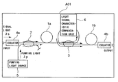
- FIG. 1 shows a configuration of an optical amplifier of a first embodiment of the present invention.
- An optical amplifier AO 1 comprises rare earth doped fibers 1 a and 1 b which are optical amplifying media, wavelength multiplexing/demultiplexing unit 2 and 3 , optical isolators 4 a and 4 b, a pumping light source 5 and a light signal characteristic compensation unit 6 .
- the light signal characteristic compensation unit 6 may be a high dispersion fiber having a reverse dispersion property or an optical resonator such as ethron, which compensates for the dispersion of a transmission line optical fiber, and for a wavelength multiplexing transmission system, it may be a wavelength dependent equalizing optical filter having an optical amplifying medium gain.
- a signal light wavelength is ⁇ s shown by a solid line arrow and a pumping light wavelength ⁇ p is shown by a broken line arrow.
- the signal light and the pumping light are applied to the rare earth doped optical fiber 1 a through the optical isolator 4 a and the wavelength multiplexing/demultiplexing unit 2 , and through the wavelength multiplexing/demultiplexing unit 2 , respectively, so that the signal light is amplified.
- a port which is not used by the wavelength multiplexing/demultiplexing unit 2 it is terminated by an oblique end of the optical fiber.
- the signal light then passes -through the wavelength multiplexing/demultiplexing unit 3 , the light signal characteristic compensation unit 6 and the wavelength multiplexing/demultiplexing unit 3 in sequence, and the pumping light is applied to a next stage rare earth doped optical fiber 1 b through only the wavelength multiplexing/ demultiplexing unit 3 and the signal light is again amplified.
- a signal input is large because the signal light has already been amplified by the rare earth doped optical fiber 1 a and it is in a gain saturation state and the gain is low.
- the signal input is lowered and the rare earth doped optical fiber 1 b approaches the non-saturation state and the gain rises.
- the loss of the light signal characteristics compensation unit 6 is compensated by the rare earth doped optical fiber 1 b and the gain as viewed by the overall optical amplifier AO 1 is not lowered by the loss compared with non-loss state of the light signal characteristic compensation unit 6 .
- FIG. 2 an effect of the first embodiment is explained.
- the optical amplifier of the configuration of FIG. 1 is actually constructed and a gain and a noise figure (only a beat noise component between a signal and an amplified spontaneously emitted light is considered) are actually measured with respect to an input signal light power.
- a signal light wavelength is 1552 nm
- a pumping light wavelength is 980 nm.
- optical attenuators with losses of 5 dB and 10 dB are inserted.
- a mark ⁇ is for the loss of 5 dB by the optical attenuator, a mark ⁇ is for the loss of 10 dB by the optical attenuator and a mark ⁇ is for non-insertion of the optical attenuator (0 dB of loss).
- a pumping light power applied to the rare earth doped optical fiber 1 a is 50 mW constant irrespective of the presence or absence of the loss.
- the input signal light power is smaller than ⁇ 20 dBm
- the reduction of gain for the 5 dB loss is approximately 2 dB
- the reduction of gain for the 10 dB loss is approximately 4 dB, which is less than one half of the loss.
- the noise figure is substantially constant around 5 dB for the respective losses.
- the present experiment shows that, in the optical amplifier of the first embodiment of the present invention, the loss of the light signal characteristic compensation unit can be compensated without increasing the pumping light power. It further indicates that no significant change appears in the noise figure.
- FIG. 3 shows a configuration of a second embodiment of the optical amplifier of the present invention.
- An optical amplifier A 02 comprises rare earth doped optical fibers 1 a and 1 b which are optical amplifying media, wavelength multiplexing/demultiplexing units 2 , 3 a and 3 b, optical isolators 4 a and 4 b, a pumping light source 5 and a light signal characteristic compensation unit 6 .
- a signal light and a pumping light are applied to the rare earth doped optical fiber 1 a through the optical isolator 4 a and the wavelength multiplexing/demultiplexing unit 2 and through the wavelength multiplexing/demultiplexing unit 2 , respectively, and the signal light is amplified.
- the signal light then passes through the wavelength multiplexing/demultiplexing unit 3 a, the light signal characteristic compensation unit 6 and the wavelength multiplexing/demultiplexing unit 3 b in sequence, and the pumping light is applied to the next stage rare earth doped optical fiber 1 b through only the wavelength multiplexing/demultiplexing units 3 a and 3 b so that the signal light is amplified again.
- the same effect as that of the first embodiment is attained.
- FIG. 4 shows a configuration of a third embodiment of the optical amplifier of the present invention.
- An optical amplifier A 03 comprises rare earth doped optical fibers 1 a and 1 b which are optical amplifying media, wavelength multiplexing/demultiplexing units 2 and 3 , optical isolators 4 a and 4 b, a pumping light source 5 and a light signal characteristic compensation unit 6 .
- a signal light is applied to the rare earth doped optical fiber 1 a through the optical isolator 4 a and is amplified by the pumping light which passes through the wavelength multiplexing/demultiplexing unit 2 , the rare earth doped optical fiber 1 b and the wavelength multiplexing/demultiplexing unit 3 in sequence.
- the signal light then passes through the wavelength multiplexing/demultiplexing unit 3 , the light signal characteristic compensation unit 6 and the wavelength multiplexing/demultiplexing unit 3 in sequence and is applied to the next stage rare earth doped optical fiber 1 b pumped through the wavelength multiplexing/demultiplexing unit 2 so that the signal light is amplified again.
- the same effect as that of the first embodiment is attained.
- FIG. 5 shows a configuration of a fourth embodiment of the optical amplifier of the present invention.
- An optical amplifier A 04 comprises rare earth doped optical fibers 1 a and 1 b which are optical amplifying media, wavelength multiplexing/demultiplexing units 2 a and 2 b, optical isolators 4 a and 4 b, pumping light sources 5 a and 5 b and a light signal characteristic compensation unit 6 .
- a signal light is applied to the rare earth doped optical fiber 1 a through the optical isolator 4 a and the wavelength multiplexing/demultiplexing unit 2 a, and is amplified by a first pumping light ( 5 a ) passed through the wavelength multiplexing/demultiplexing unit 2 a and a second pumping light ( 5 b ) passed through the wavelength multiplexing/demultiplexing unit 2 b, the rare earth doped optical fiber 1 b and the wavelength multiplexing/demultiplexing unit 3 in sequence.
- the signal light then passes through the wavelength multiplexing/demultiplexing unit 3 , the light signal characteristic compensation unit 6 and the wavelength multiplexing/demultiplexing unit 3 in sequence, and the first pumping light and the second pumping light are applied to the next stage rare earth doped optical fiber 1 b through the wavelength multiplexing/demultiplexing unit 3 and through the wavelength multiplexing/demultiplexing unit 2 , respectively so that the signal light is amplified again.
- the same effect as that of the first embodiment is attained.
- FIG. 6 shows a configuration of a fifth embodiment of the optical amplifier of the present invention.
- An optical amplifier A 05 comprises rare earth doped optical fibers 1 a and 1 b which are optical amplifying media, wavelength multiplexing/demultiplexing units 2 a, 2 b and 3 , optical isolators 4 a and 4 b, a pumping light source 5 , a light signal characteristic compensation unit 6 and a reflection mirror 7 .
- a signal light is applied to the rare earth doped optical fiber 1 a through the optical isolator 4 a and the wavelength multiplexing/demultiplexing unit 2 a.
- a pumping light is applied to the rare earth doped optical fiber 1 a through the wavelength multiplexing/demultiplexing unit 2 a, and the pumping light which is not consumed in the rare earth doped optical fiber 1 a passes through the wavelength multiplexing/demultiplexing unit 3 , the rare earth doped optical fiber 1 b and the wavelength multiplexing/demultiplexing unit 2 b and is reflected by the reflection mirror 7 , and passes through the same path and is directed to the rare earth doped optical fiber 1 a so that the signal light is amplified.
- the signal light then passes through the wavelength multiplexing/demultiplexing unit 3 , the light signal characteristic compensation unit 6 and the wavelength multiplexing/demultiplexing unit 3 in sequence, and the signal light and the pumping light are applied to the next stage rare earth doped optical fiber 1 b through the wavelength multiplexing/demultiplexing unit 3 and through the wavelength multiplexing/demultiplexing unit 2 b, respectively so that the signal light is amplified again.
- the same effect as that of the first embodiment is attained.
- higher amplification effect is attained because the pumping light is reflected for utilization.
- FIG. 7 shows a configuration of a sixth embodiment of the present embodiment.
- An optical amplifier A 06 comprises rare earth doped optical fibers 1 a, 1 b and 1 c which are optical amplifying media, wavelength multiplexing/demultiplexing units 2 , 3 a and 3 b, optical isolators 4 a and 4 b, a pumping light source 5 and light signal characteristic compensation units 6 a and 6 b.
- a signal light is applied to the rare earth doped optical fiber 1 a through the optical isolator 4 a and the wavelength multiplexing/demultiplexing unit 2 .
- a pumping light is applied to the rare earth doped optical fiber 1 a through the wavelength multiplexing/demultiplexing unit 2 so that the signal light is amplified.
- the signal light then passes through the wavelength multiplexing/demultiplexing unit 3 a, the light signal characteristic compensation unit 6 a and the wavelength multiplexing/demultiplexing unit in sequence, and the pumping light is applied to the rare earth doped optical fiber 1 b through the wavelength multiplexing/demultiplexing unit 3 a so that the signal light is amplified again.
- the signal light passes through the wavelength multiplexing/demultiplexing unit 3 b, the light signal characteristic compensation unit 6 b and the wavelength multiplexing/demultiplexing unit 3 b in sequence, and the pumping light is applied to the next stage rare earth doped optical fiber 1 c through the wavelength multiplexing/demultiplexing unit 3 b so that the signal light is amplified again.
- the number of optical amplifying media need not be two but it may be three or more. In the present embodiment, the same effect as that of the first embodiment is attained. Further, in the present embodiment, a plurality of light signal compensation units may be built in the optical amplifier and a combined characteristic compensation may be attained.
- FIGS. 8 - 10 show configurations of seventh to ninth embodiments of the optical amplifier of the present invention.
- the configurations are similar to that of the first embodiment shown in FIG. 1 except that an optical part 4 c is arranged in an input of the light signal characteristic compensation unit 6 (FIG. 8), an output (FIG. 9) and input/output (FIG. 10).
- the optical part 4 c may be an optical isolator, which is explained below.
- the light signal characteristic compensation unit 6 may be a dispersion compensating optical fiber and a reflected light by the Rayleigh scattering of the fiber or from an optical connector is returned to the optical amplifying media so that the amplification characteristic of the light signal may be deteriorated.
- the optical isolator By inserting the optical isolator, the reflected light is suppressed.
- the optical isolator blocks the opposite direction spontaneous emission light traveling from the optical amplifying medium 1 b to the optical amplifying medium 1 a. Accordingly, a higher gain and lower noise optical amplifier is attained.
- the optical part 4 c is, an optical band-pass filter.
- the optical band-pass filter equalizes only the light in the vicinity of the signal light and suppresses the extra spontaneous emission and amplified light outside of the signal band to enter the next stage or preceding stage optical amplifying medium.
- a 10 similar high gain and low noise optical amplifier is attained.
- the optical part 4 c is a complex optical part having an optical isolator and an optical band-pass filter serially connected, the effect of the insertion of the optical isolator and the effect of the insertion of the optical band-pass filter are simultaneously attained so that a higher gain and lower noise optical amplifier is attained.
- FIG. 11 shows a configuration of a first embodiment of an optical transmission system using the optical amplifier of the present invention. It comprises an optical transmitter 100 , a transmission line optical fiber 106 , and an optical receiver 200 .
- the optical transmitter 100 comprises an electro-optical converter 104 and an optical amplifier 105 having a light signal characteristic compensation unit built therein.
- the optical amplifier 105 may be one of the optical amplifiers shown in the first to ninth embodiments.
- the optical transmission system which can suppress the deterioration of the gain of the optical amplifier or the noise characteristic due to the build-in of the light signal characteristic compensation unit in the optical transmitter is attained.
- FIG. 12 shows a configuration of a second embodiment of the optical transmission system using the optical amplifier of the present invention. It comprises an optical amplifier 100 , a transmission line optical fiber 106 and an-optical receiver 200 .
- the optical receiver 200 comprises an optical amplifier 206 having a light signal characteristic compensation unit built therein and a photo-electrical converter 205 .
- the optical amplifier 206 may be one of the optical amplifiers shown in the first to ninth embodiments.
- an optical transmission system which suppresses the deterioration of the gain of the optical amplifier or the noise characteristic due to the built-in of the light signal characteristic compensation unit in the optical receiver is attained.
- FIG. 13 shows a configuration of a third embodiment of the optical transmission system using the optical amplifier of the present invention. It comprises an optical transmitter 100 , a transmission line optical fiber 106 , an optical amplifying repeater 300 and an optical receiver 200 .
- the optical amplifying repeater 300 may be one of the optical amplifiers shown in the first to ninth embodiments.
- an optical transmission system which suppresses the deterioration of the gain of the optical amplifier or the noise characteristic due to the built-in of the light signal characteristic compensation unit in the optical amplifying relay is attained.
- the optical amplifier which compensates for the loss of the light signal characteristic compensation unit and suppresses the reduction of the optical output and the increase of the noise figure without increasing the pumping light power and the number of pumping light sources is attained. Accordingly, the optical amplifier of a simple and inexpensive construction having the reduction of the gain and the increase of the noise figure suppressed is attained while adding a new function such as the dispersion compensation.
Abstract
A method of amplifying a signal light includes initially multiplexing a signal light and a pumping light, initially amplifying the signal light initially demultiplexing so as to separately output the amplified signal light and the pumping light, and modifying a waveform of the amplified signal light so as to compensate for waveform distortion of the signal light along a transmission path of the signal light and providing an output of a waveform modified signal light. Thereafter, the waveform modified signal lights is secondarily multiplexed, secondarily amplified, and secondarily demultiplexed with a waveform of amplified signal light being compensated for waveform distortion of the signal light along a transmission path of the signal light an output of a waveform modified signal light. The waveform modified signal light is thirdly multiplexed and thirdly amplified so as to provide an output of amplified waveform modified signal light.
Description
- This is a continuation of U.S. application Ser. No. 10/270,648, filed Oct. 16, 2002, which is a continuation of U.S. application Ser. No. 09/585,280, Filed Jun. 2, 2000, NOW U.S. Pat. No. 6,542,290, which is a continuation of 09/069,772, filed Apr. 30, 1998, now U.S. Pat. No. 6,091,540, which is a continuation of U.S. application Ser. No. 08/432,074, filed May 1, 1995, now U.S. Pat. No. 5,831,754, the subject matter of which is incorporated by reference herein.
- The present invention relates to an optical amplifier applied to an optical transmission apparatus such as an optical transmitter/receiver apparatus or an optical repeater in an optical communication system.
- In the prior art, a dispersion compensating fiber is used in an optical receiver or an optical transmitter in order to suppress a waveform distortion of an optical signal due to a waveform dispersion of a transmission line fiber, but because of its large loss, it is essential to use it with an optical amplifier for compensating the loss. This technique is disclosed in OSA Optical Fiber Communication Conference, 1992, pp. 367-370.
- FIG. 14 shows a configuration of an optical fiber transmission system which uses a prior art dispersion compensating
optical transmitter 100 and a prior art dispersion compensatingoptical receiver 200. Theoptical transmitter 100 comprises an erbium doped optical fiber amplifier 101 a, adispersion compensating fiber 103 a and an electro-optical converter 104. Theoptical receiver 200 comprises erbium dopedoptical fiber amplifiers pass filters dispersion compensating fibers electric converter 205. Losses of the dispersion compensating fibers used are 3.1 dB, 10.6 dB and 5.3 dB, respectively for a light signal level. In order to compensate for the losses, a total of three erbium doped optical fibers are used, which amplify the signal lights by using separate pumping light sources. A characteristic of the optical fiber amplifier when the dispersion compensating fiber is added is that a noise figure is increased by a loss when the dispersion compensating fiber is arranged in a preceding stage, and a light output is decreased by the loss when the dispersion compensating fiber is arranged in a succeeding stage. - In the known dispersion compensating optical transmitter and dispersion compensating optical receiver shown in FIG. 14, the light signal level is lowered because of a large loss of the dispersion compensating fiber. When the optical amplifier is used to compensate for the loss, the light output of the optical amplifier decreases and the problem of increase of the noise figure arises. In order to avoid the problem, it is necessary to arrange a separate optical amplifier.
- It is an object of the present invention to provide an optical amplifier which can suppress the decrease of the light output and the increase of the noise figure without increasing the pumping light power or increasing the number of pumping light sources even when a lossy dispersion compensation unit is used.
- In order to achieve the above object, in accordance with the optical amplifier of the present invention, an optical amplifying medium is divided and a wavelength multiplexing/demultiplexing unit for multiplexing or demultiplexing a pumping light and a signal light is provided in a division, and the pumping light is directly transmitted to a next stage optical amplifying medium while the signal light is transmitted to the next stage optical amplifying medium through an optical signal characteristic compensation unit such as a dispersion compensating fiber so that the reduction of the optical signal level due to the loss of the optical signal characteristic compensation unit is suppressed.
- In the optical amplifier of the present invention, the signal light level is lowered by the passage through the optical signal characteristic compensation unit but it is again amplified by the next stage optical amplifying medium by using the pumping light which is not consumed by the preceding stage optical amplifying medium. In the next stage optical amplifying medium, since the input light power is low, it approaches a non-saturation state and a gain increases. As a result, it is possible to set the gain of the next stage optical amplifying medium higher than the loss of the optical signal characteristic compensation unit. By setting the gain of the preceding stage optical amplifying medium sufficiently large, the noise figure of the optical amplifier is essentially determined by the preceding stage and an effect of the loss of the inserted optical signal characteristic compensation unit to the noise figure is suppressed.
- FIG. 1 shows a configuration of a first embodiment of an optical amplifier,
- FIG. 2 illustrates an effect of the optical amplifier of the first embodiment,
- FIG. 3 shows a configuration of a second embodiment of the optical amplifier,
- FIG. 4 shows a configuration of a third embodiment of the optical amplifier,
- FIG. 5 shows a configuration of a fourth embodiment of the optical amplifier,
- FIG. 6 shows a configuration of a fifth embodiment of the optical amplifier,
- FIG. 7 shows a configuration of a sixth embodiment of the optical amplifier,
- FIG. 8 shows a configuration of a seventh embodiment of the optical amplifier,
- FIG. 9 shows a configuration of an eighth embodiment of the optical amplifier,
- FIG. 10 shows a configuration of a ninth embodiment of the optical amplifier,
- FIG. 11 shows a configuration of a first embodiment of an optical transmission system,
- FIG. 12 shows a configuration of a second embodiment of an optical transmission system,
- FIG. 13 shows a configuration of a third embodiment of an optical transmission system, and
- FIG. 14 shows a configuration of a prior art optical transmission system using a dispersion compensating optical fiber in an optical transmitter/receiver.
- An embodiment of the present invention is now explained in conjunction with the accompanying drawings. FIG. 1 shows a configuration of an optical amplifier of a first embodiment of the present invention. An optical amplifier AO 1 comprises rare earth doped
fibers demultiplexing unit optical isolators pumping light source 5 and a light signalcharacteristic compensation unit 6. The light signalcharacteristic compensation unit 6 may be a high dispersion fiber having a reverse dispersion property or an optical resonator such as ethron, which compensates for the dispersion of a transmission line optical fiber, and for a wavelength multiplexing transmission system, it may be a wavelength dependent equalizing optical filter having an optical amplifying medium gain. In FIG. 1, a signal light wavelength is λs shown by a solid line arrow and a pumping light wavelength λp is shown by a broken line arrow. The signal light and the pumping light are applied to the rare earth dopedoptical fiber 1 a through theoptical isolator 4 a and the wavelength multiplexing/demultiplexing unit 2, and through the wavelength multiplexing/demultiplexing unit 2, respectively, so that the signal light is amplified. For a port which is not used by the wavelength multiplexing/demultiplexing unit 2, it is terminated by an oblique end of the optical fiber. The signal light then passes -through the wavelength multiplexing/demultiplexing unit 3, the light signalcharacteristic compensation unit 6 and the wavelength multiplexing/demultiplexing unit 3 in sequence, and the pumping light is applied to a next stage rare earth dopedoptical fiber 1 b through only the wavelength multiplexing/demultiplexing unit 3 and the signal light is again amplified. Normally, in the rare earth dopedoptical fiber 1 b, a signal input is large because the signal light has already been amplified by the rare earth dopedoptical fiber 1 a and it is in a gain saturation state and the gain is low. In the configuration of the present embodiment, however, since only the signal light suffers from the loss by the light signalcharacteristic compensation unit 6, the signal input is lowered and the rare earth dopedoptical fiber 1 b approaches the non-saturation state and the gain rises. As a result, the loss of the light signalcharacteristics compensation unit 6 is compensated by the rare earth dopedoptical fiber 1 b and the gain as viewed by the overall optical amplifier AO1 is not lowered by the loss compared with non-loss state of the light signalcharacteristic compensation unit 6. - Referring to FIG. 2, an effect of the first embodiment is explained. The optical amplifier of the configuration of FIG. 1 is actually constructed and a gain and a noise figure (only a beat noise component between a signal and an amplified spontaneously emitted light is considered) are actually measured with respect to an input signal light power. A signal light wavelength is 1552 nm, and a pumping light wavelength is 980 nm. In order to examine an effect of the loss of the light signal
characteristic compensation unit 6, optical attenuators with losses of 5 dB and 10 dB are inserted. A mark □ is for the loss of 5 dB by the optical attenuator, a mark □ is for the loss of 10 dB by the optical attenuator and a mark □ is for non-insertion of the optical attenuator (0 dB of loss). A pumping light power applied to the rare earth dopedoptical fiber 1 a is 50 mW constant irrespective of the presence or absence of the loss. When the input signal light power is smaller than −20 dBm, the reduction of gain for the 5 dB loss is approximately 2 dB, and the reduction of gain for the 10 dB loss is approximately 4 dB, which is less than one half of the loss. On the other hand, the noise figure is substantially constant around 5 dB for the respective losses. The present experiment shows that, in the optical amplifier of the first embodiment of the present invention, the loss of the light signal characteristic compensation unit can be compensated without increasing the pumping light power. It further indicates that no significant change appears in the noise figure. - FIG. 3 shows a configuration of a second embodiment of the optical amplifier of the present invention. An optical amplifier A 02 comprises rare earth doped
optical fibers demultiplexing units optical isolators light source 5 and a light signalcharacteristic compensation unit 6. A signal light and a pumping light are applied to the rare earth dopedoptical fiber 1 a through theoptical isolator 4 a and the wavelength multiplexing/demultiplexing unit 2 and through the wavelength multiplexing/demultiplexing unit 2, respectively, and the signal light is amplified. The signal light then passes through the wavelength multiplexing/demultiplexing unit 3 a, the light signalcharacteristic compensation unit 6 and the wavelength multiplexing/demultiplexing unit 3 b in sequence, and the pumping light is applied to the next stage rare earth dopedoptical fiber 1 b through only the wavelength multiplexing/demultiplexing units - FIG. 4 shows a configuration of a third embodiment of the optical amplifier of the present invention. An optical amplifier A 03 comprises rare earth doped
optical fibers demultiplexing units optical isolators light source 5 and a light signalcharacteristic compensation unit 6. A signal light is applied to the rare earth dopedoptical fiber 1 a through theoptical isolator 4 a and is amplified by the pumping light which passes through the wavelength multiplexing/demultiplexing unit 2, the rare earth dopedoptical fiber 1 b and the wavelength multiplexing/demultiplexing unit 3 in sequence. The signal light then passes through the wavelength multiplexing/demultiplexing unit 3, the light signalcharacteristic compensation unit 6 and the wavelength multiplexing/demultiplexing unit 3 in sequence and is applied to the next stage rare earth dopedoptical fiber 1 b pumped through the wavelength multiplexing/demultiplexing unit 2 so that the signal light is amplified again. In the present embodiment, the same effect as that of the first embodiment is attained. - FIG. 5 shows a configuration of a fourth embodiment of the optical amplifier of the present invention. An optical amplifier A 04 comprises rare earth doped
optical fibers demultiplexing units optical isolators light sources characteristic compensation unit 6. A signal light is applied to the rare earth dopedoptical fiber 1 a through theoptical isolator 4 a and the wavelength multiplexing/demultiplexing unit 2 a, and is amplified by a first pumping light (5 a) passed through the wavelength multiplexing/demultiplexing unit 2 a and a second pumping light (5 b) passed through the wavelength multiplexing/demultiplexing unit 2 b, the rare earth dopedoptical fiber 1 b and the wavelength multiplexing/demultiplexing unit 3 in sequence. The signal light then passes through the wavelength multiplexing/demultiplexing unit 3, the light signalcharacteristic compensation unit 6 and the wavelength multiplexing/demultiplexing unit 3 in sequence, and the first pumping light and the second pumping light are applied to the next stage rare earth dopedoptical fiber 1 b through the wavelength multiplexing/demultiplexing unit 3 and through the wavelength multiplexing/demultiplexing unit 2, respectively so that the signal light is amplified again. In the present embodiment, the same effect as that of the first embodiment is attained. - FIG. 6 shows a configuration of a fifth embodiment of the optical amplifier of the present invention. An optical amplifier A 05 comprises rare earth doped
optical fibers demultiplexing units optical isolators light source 5, a light signalcharacteristic compensation unit 6 and areflection mirror 7. A signal light is applied to the rare earth dopedoptical fiber 1 a through theoptical isolator 4 a and the wavelength multiplexing/demultiplexing unit 2 a. A pumping light is applied to the rare earth dopedoptical fiber 1 a through the wavelength multiplexing/demultiplexing unit 2 a, and the pumping light which is not consumed in the rare earth dopedoptical fiber 1 a passes through the wavelength multiplexing/demultiplexing unit 3, the rare earth dopedoptical fiber 1 b and the wavelength multiplexing/demultiplexing unit 2 b and is reflected by thereflection mirror 7, and passes through the same path and is directed to the rare earth dopedoptical fiber 1 a so that the signal light is amplified. The signal light then passes through the wavelength multiplexing/demultiplexing unit 3, the light signalcharacteristic compensation unit 6 and the wavelength multiplexing/demultiplexing unit 3 in sequence, and the signal light and the pumping light are applied to the next stage rare earth dopedoptical fiber 1 b through the wavelength multiplexing/demultiplexing unit 3 and through the wavelength multiplexing/demultiplexing unit 2 b, respectively so that the signal light is amplified again. In the present embodiment, the same effect as that of the first embodiment is attained. In the present embodiment, higher amplification effect is attained because the pumping light is reflected for utilization. - FIG. 7 shows a configuration of a sixth embodiment of the present embodiment. An optical amplifier A 06 comprises rare earth doped
optical fibers demultiplexing units optical isolators light source 5 and light signalcharacteristic compensation units optical fiber 1 a through theoptical isolator 4 a and the wavelength multiplexing/demultiplexing unit 2. A pumping light is applied to the rare earth dopedoptical fiber 1 a through the wavelength multiplexing/demultiplexing unit 2 so that the signal light is amplified. The signal light then passes through the wavelength multiplexing/demultiplexing unit 3 a, the light signalcharacteristic compensation unit 6 a and the wavelength multiplexing/demultiplexing unit in sequence, and the pumping light is applied to the rare earth dopedoptical fiber 1 b through the wavelength multiplexing/demultiplexing unit 3 a so that the signal light is amplified again. The signal light passes through the wavelength multiplexing/demultiplexing unit 3 b, the light signalcharacteristic compensation unit 6 b and the wavelength multiplexing/demultiplexing unit 3 b in sequence, and the pumping light is applied to the next stage rare earth doped optical fiber 1 c through the wavelength multiplexing/demultiplexing unit 3 b so that the signal light is amplified again. The number of optical amplifying media need not be two but it may be three or more. In the present embodiment, the same effect as that of the first embodiment is attained. Further, in the present embodiment, a plurality of light signal compensation units may be built in the optical amplifier and a combined characteristic compensation may be attained. - FIGS. 8-10 show configurations of seventh to ninth embodiments of the optical amplifier of the present invention. The configurations are similar to that of the first embodiment shown in FIG. 1 except that an
optical part 4 c is arranged in an input of the light signal characteristic compensation unit 6 (FIG. 8), an output (FIG. 9) and input/output (FIG. 10). Theoptical part 4 c may be an optical isolator, which is explained below. The light signalcharacteristic compensation unit 6 may be a dispersion compensating optical fiber and a reflected light by the Rayleigh scattering of the fiber or from an optical connector is returned to the optical amplifying media so that the amplification characteristic of the light signal may be deteriorated. By inserting the optical isolator, the reflected light is suppressed. The optical isolator blocks the opposite direction spontaneous emission light traveling from the optical amplifying medium 1 b to the optical amplifying medium 1 a. Accordingly, a higher gain and lower noise optical amplifier is attained. - It is now assumed that the
optical part 4 c is, an optical band-pass filter. The optical band-pass filter equalizes only the light in the vicinity of the signal light and suppresses the extra spontaneous emission and amplified light outside of the signal band to enter the next stage or preceding stage optical amplifying medium. Thus, a 10 similar high gain and low noise optical amplifier is attained. - When the
optical part 4 c is a complex optical part having an optical isolator and an optical band-pass filter serially connected, the effect of the insertion of the optical isolator and the effect of the insertion of the optical band-pass filter are simultaneously attained so that a higher gain and lower noise optical amplifier is attained. - FIG. 11 shows a configuration of a first embodiment of an optical transmission system using the optical amplifier of the present invention. It comprises an
optical transmitter 100, a transmission lineoptical fiber 106, and anoptical receiver 200. Theoptical transmitter 100 comprises an electro-optical converter 104 and anoptical amplifier 105 having a light signal characteristic compensation unit built therein. Theoptical amplifier 105 may be one of the optical amplifiers shown in the first to ninth embodiments. In accordance with the present embodiment, the optical transmission system which can suppress the deterioration of the gain of the optical amplifier or the noise characteristic due to the build-in of the light signal characteristic compensation unit in the optical transmitter is attained. - FIG. 12 shows a configuration of a second embodiment of the optical transmission system using the optical amplifier of the present invention. It comprises an
optical amplifier 100, a transmission lineoptical fiber 106 and an-optical receiver 200. Theoptical receiver 200 comprises anoptical amplifier 206 having a light signal characteristic compensation unit built therein and a photo-electrical converter 205. Theoptical amplifier 206 may be one of the optical amplifiers shown in the first to ninth embodiments. In accordance with the present embodiment, an optical transmission system which suppresses the deterioration of the gain of the optical amplifier or the noise characteristic due to the built-in of the light signal characteristic compensation unit in the optical receiver is attained. - FIG. 13 shows a configuration of a third embodiment of the optical transmission system using the optical amplifier of the present invention. It comprises an
optical transmitter 100, a transmission lineoptical fiber 106, anoptical amplifying repeater 300 and anoptical receiver 200. Theoptical amplifying repeater 300 may be one of the optical amplifiers shown in the first to ninth embodiments. In accordance with the present embodiment, an optical transmission system which suppresses the deterioration of the gain of the optical amplifier or the noise characteristic due to the built-in of the light signal characteristic compensation unit in the optical amplifying relay is attained. - In accordance with the present invention, the optical amplifier which compensates for the loss of the light signal characteristic compensation unit and suppresses the reduction of the optical output and the increase of the noise figure without increasing the pumping light power and the number of pumping light sources is attained. Accordingly, the optical amplifier of a simple and inexpensive construction having the reduction of the gain and the increase of the noise figure suppressed is attained while adding a new function such as the dispersion compensation.
Claims (12)
1. A method of amplifying a signal light comprising the steps of:
initially multiplexing a signal light and a pumping light from a pumping light source so as to output the signal light and the pumping light;
initially amplifying the signal light by utilizing the pumping light and providing an output of amplified signal light;
receiving the amplified signal light and the pumping light and initially demultiplexing so as to separately output the amplified signal light and the pumping light;
receiving the amplified signal light and modifying a waveform of the amplified signal light so as to compensate for waveform distortion of the signal light along a transmission path of the signal light and providing an output of a waveform modified signal light;
secondarily multiplexing the waveform modified signal light which is received and the pumping light which is received so as to output the waveform modified signal light and the pumping light;
secondarily amplifying the waveform modified signal light by utilizing the pumping light and providing an output of amplified waveform modified signal light so that a reduction of optical signal level due to loss caused by compensation for the waveform distortion of the signal light is suppressed;
receiving the amplified signal light and the pumping light and secondarily demultiplexing so as to separately output the amplified signal light and the pumping light;
receiving the amplified signal light and modifying a waveform of the amplified signal light so as to compensate for waveform distortion of the signal light along a transmission path of the signal light and providing an output of a waveform modified signal light;
thirdly multiplexing the waveform modified signal light which is received and the pumping light which is received so as to output the waveform modified signal light and the pumping light; and
thirdly amplifying the waveform modified signal light by utilizing the pumping light and providing an output of amplified waveform modified signal light so that a reduction of optical signal level due to loss caused by compensation for the waveform distortion of the signal light is suppressed.
2. A method of amplifying a signal light according to claim 1 , wherein the signal light includes light at plural wavelength, and the step of modifying the waveform of the amplified signal light includes utilizing a wavelength dependent equalizing filter and providing the output of the waveform modified signal light which is wavelength equalized.
3. A method of amplifying a signal light according to claim 1 , wherein the steps of initially demultiplexing and secondarily multiplexing are performed in a single unit.
4. A method of amplifying a signal light according to claim 1 , wherein the steps of secondarily demultiplexing and thirdly multiplexing are performed in a single unit.
5. A method of receiving a signal light comprising the steps of:
amplifying a signal light according to claim 1 including providing an output signal light; and
receiving the output signal light and converting the received output signal light to an electric signal.
6. A method of transmission of a signal light comprising the steps of:
amplifying a signal light according to claim 1 including providing an output signal light; and
transmitting the output signal light to a receiver.
7. A method of amplifying a signal light comprising the steps of:
initially multiplexing a signal light and a pumping light from a pumping light source so as to output the signal light and the pumping light;
initially amplifying the signal light by utilizing the pumping light and providing an output of amplified signal light;
receiving the amplified signal light and the pumping light and initially demultiplexing so as to separately output the amplified signal light and the pumping light;
initially compensating for distortion of the signal light including receiving the amplified signal light and modifying a waveform of the amplified signal light so as to compensate for waveform distortion of the signal light along a transmission path of the signal light and providing an output of a waveform modified signal light;
secondarily multiplexing the waveform modified signal light which is received and the pumping light which is received so as to output the waveform modified signal light and the pumping light;
secondarily amplifying the waveform modified signal light by utilizing the pumping light and providing an output of amplified waveform modified signal light so that a reduction of optical signal level due to loss caused by compensation for the waveform distortion of the signal light is suppressed;
receiving the amplified signal light and the pumping light and secondarily demultiplexing so as to separately output the amplified signal light and the pumping light;
secondarily compensating for distortion of the signal light including receiving the amplified signal light and modifying a waveform of the amplified signal light so as to compensate for waveform distortion of the signal light along a transmission path of the signal light and providing an output of a waveform modified signal light;
thirdly multiplexing the waveform modified signal light which is received and the pumping light which is received so as to output the waveform modified signal light and the pumping light; and
thirdly amplifying the waveform modified signal light by utilizing the pumping light and providing an output of amplified waveform modified signal light so that a reduction of optical signal level due to loss caused by compensation for the waveform distortion of the signal light is suppressed.
8. A method of amplifying a signal light according to claim 7 , wherein the signal light includes light at plural wavelength, and the step of modifying the waveform of the amplified signal light includes utilizing a wavelength dependent equalizing filter and providing the output of the waveform modified signal light which is wavelength equalized.
9. A method of amplifying a signal light according to claim 7 , wherein the steps of initially demultiplexing and secondarily multiplexing are performed in a single unit.
10. A method of amplifying a signal light according to claim 7 , wherein the steps of secondarily demultiplexing and thirdly multiplexing are performed in a single unit.
11. A method of receiving a signal light comprising the step of:
amplifying a signal light according to claim 7 including providing an output signal light; and
receiving the output signal light and converting the received output signal light to an electric signal.
12. A method of transmission of a signal light comprising the step of:
amplifying a signal light according to claim 7 including providing an output signal light; and
transmitting the output signal light to a receiver.
Priority Applications (2)
| Application Number | Priority Date | Filing Date | Title |
|---|---|---|---|
| US10/445,944 US6747792B2 (en) | 1994-05-06 | 2003-05-28 | Optical amplifying method |
| US10/859,167 US6927897B2 (en) | 1994-05-06 | 2004-06-03 | Optical amplifier |
Applications Claiming Priority (8)
| Application Number | Priority Date | Filing Date | Title |
|---|---|---|---|
| JP06-094136 | 1994-05-06 | ||
| JP09413694A JP3195160B2 (en) | 1994-05-06 | 1994-05-06 | Optical amplifier |
| JP6-094136 | 1994-05-06 | ||
| US08/432,074 US5831754A (en) | 1994-05-06 | 1995-05-01 | Optical amplifier |
| US09/069,772 US6091540A (en) | 1994-05-06 | 1998-04-30 | Optical amplifier |
| US09/585,280 US6542290B1 (en) | 1994-05-06 | 2000-06-02 | Optical amplifier |
| US10/270,648 US6577439B2 (en) | 1994-05-06 | 2002-10-16 | Optical amplifier |
| US10/445,944 US6747792B2 (en) | 1994-05-06 | 2003-05-28 | Optical amplifying method |
Related Parent Applications (1)
| Application Number | Title | Priority Date | Filing Date |
|---|---|---|---|
| US10/270,648 Continuation US6577439B2 (en) | 1994-05-06 | 2002-10-16 | Optical amplifier |
Related Child Applications (1)
| Application Number | Title | Priority Date | Filing Date |
|---|---|---|---|
| US10/859,167 Continuation US6927897B2 (en) | 1994-05-06 | 2004-06-03 | Optical amplifier |
Publications (2)
| Publication Number | Publication Date |
|---|---|
| US20030197920A1 true US20030197920A1 (en) | 2003-10-23 |
| US6747792B2 US6747792B2 (en) | 2004-06-08 |
Family
ID=14101987
Family Applications (6)
| Application Number | Title | Priority Date | Filing Date |
|---|---|---|---|
| US08/432,074 Expired - Lifetime US5831754A (en) | 1994-05-06 | 1995-05-01 | Optical amplifier |
| US09/069,772 Expired - Lifetime US6091540A (en) | 1994-05-06 | 1998-04-30 | Optical amplifier |
| US09/585,280 Expired - Fee Related US6542290B1 (en) | 1994-05-06 | 2000-06-02 | Optical amplifier |
| US10/270,648 Expired - Fee Related US6577439B2 (en) | 1994-05-06 | 2002-10-16 | Optical amplifier |
| US10/445,944 Expired - Fee Related US6747792B2 (en) | 1994-05-06 | 2003-05-28 | Optical amplifying method |
| US10/859,167 Expired - Fee Related US6927897B2 (en) | 1994-05-06 | 2004-06-03 | Optical amplifier |
Family Applications Before (4)
| Application Number | Title | Priority Date | Filing Date |
|---|---|---|---|
| US08/432,074 Expired - Lifetime US5831754A (en) | 1994-05-06 | 1995-05-01 | Optical amplifier |
| US09/069,772 Expired - Lifetime US6091540A (en) | 1994-05-06 | 1998-04-30 | Optical amplifier |
| US09/585,280 Expired - Fee Related US6542290B1 (en) | 1994-05-06 | 2000-06-02 | Optical amplifier |
| US10/270,648 Expired - Fee Related US6577439B2 (en) | 1994-05-06 | 2002-10-16 | Optical amplifier |
Family Applications After (1)
| Application Number | Title | Priority Date | Filing Date |
|---|---|---|---|
| US10/859,167 Expired - Fee Related US6927897B2 (en) | 1994-05-06 | 2004-06-03 | Optical amplifier |
Country Status (4)
| Country | Link |
|---|---|
| US (6) | US5831754A (en) |
| JP (2) | JP3195160B2 (en) |
| CN (1) | CN1044055C (en) |
| DE (1) | DE19516439A1 (en) |
Cited By (2)
| Publication number | Priority date | Publication date | Assignee | Title |
|---|---|---|---|---|
| US20100210952A1 (en) * | 2008-05-02 | 2010-08-19 | Olympus Corporation | Optical inspection device, electromagnetic wave detection method, electromagnetic wave detection device, organism observation method, microscope, endoscope, and optical tomographic image generation device |
| US20160150964A1 (en) * | 2011-10-28 | 2016-06-02 | Swat Inc. | Comprehensive measuring method of biological materials and treatment method using broadly tunable laser |
Families Citing this family (34)
| Publication number | Priority date | Publication date | Assignee | Title |
|---|---|---|---|---|
| JP3195160B2 (en) * | 1994-05-06 | 2001-08-06 | 株式会社日立製作所 | Optical amplifier |
| US6195480B1 (en) | 1997-08-06 | 2001-02-27 | Hitachi, Ltd. | Optical transmission device and optical transmission system employing the same |
| US6229936B1 (en) | 1995-05-01 | 2001-05-08 | Hitachi, Ltd. | Optical amplifier, optical transmission equipment, optical transmission system, and method thereof |
| US6321002B1 (en) | 1995-05-01 | 2001-11-20 | Hitachi, Ltd. | Optical amplifier, optical transmission equipment, optical transmission system, and method thereof |
| GB9526183D0 (en) | 1995-12-21 | 1996-02-21 | Stc Submarine Systems Ltd | Dispersion slope equalisaion for wdm systems wih branches |
| US6025947A (en) * | 1996-05-02 | 2000-02-15 | Fujitsu Limited | Controller which controls a variable optical attenuator to control the power level of a wavelength-multiplexed optical signal when the number of channels are varied |
| JPH09321701A (en) * | 1996-05-31 | 1997-12-12 | Fujitsu Ltd | Optical communication system and optical amplifier |
| US5917635A (en) * | 1996-05-30 | 1999-06-29 | Northern Telecom Limited | Optical repeaters for single-and multi-wavelength operation with dispersion equalization |
| CA2205705A1 (en) * | 1996-06-26 | 1997-12-26 | Franklin W. Kerfoot, Iii | Arrangement for reducing insertion loss impairment of optical amplifiers |
| JP3652804B2 (en) | 1996-09-06 | 2005-05-25 | 富士通株式会社 | Optical transmission equipment |
| US7054559B1 (en) * | 1997-09-04 | 2006-05-30 | Mci Communications Corporation | Method and system for modular multiplexing and amplification in a multi-channel plan |
| KR100280968B1 (en) | 1997-12-10 | 2001-02-01 | 윤종용 | Optical fiber amplifier using a synchronized etal on filter |
| US6496300B2 (en) * | 1998-02-27 | 2002-12-17 | Fujitsu Limited | Optical amplifier |
| WO1999066607A2 (en) | 1998-06-16 | 1999-12-23 | Xtera Communications, Inc. | Fiber-optic compensation for dispersion, gain tilt, and band pump nonlinearity |
| US6885498B2 (en) | 1998-06-16 | 2005-04-26 | Xtera Communications, Inc. | Multi-stage optical amplifier and broadband communication system |
| US6574037B2 (en) | 1998-06-16 | 2003-06-03 | Xtera Communications, Inc. | All band amplifier |
| JP2000031900A (en) * | 1998-07-08 | 2000-01-28 | Fujitsu Ltd | Method for optical fiber communication and terminal station device and system used for execution of the method |
| JP3769129B2 (en) * | 1998-09-03 | 2006-04-19 | 富士通株式会社 | Optical amplifier and optical communication system having chromatic dispersion compensation function |
| JP2000236297A (en) * | 1999-02-16 | 2000-08-29 | Fujitsu Ltd | Method and system for optical transmission applied with dispersion compensation |
| US6885824B1 (en) | 2000-03-03 | 2005-04-26 | Optical Coating Laboratory, Inc. | Expandable optical array |
| JP2001223641A (en) * | 2000-02-14 | 2001-08-17 | Sumitomo Electric Ind Ltd | Optical transmission system and optical transmission method |
| JP2001230477A (en) | 2000-02-16 | 2001-08-24 | Nec Corp | Light amplifier |
| US6353497B1 (en) | 2000-03-03 | 2002-03-05 | Optical Coating Laboratory, Inc. | Integrated modular optical amplifier |
| JP2001268056A (en) | 2000-03-22 | 2001-09-28 | Hitachi Ltd | Optical transmission system and wavelength multiplex/ demultiplex optical transmitter |
| US6766072B2 (en) * | 2000-07-28 | 2004-07-20 | Pirelli Cavi E Sistemi S.P.A. | Optical threshold and comparison devices and methods |
| GB0019387D0 (en) * | 2000-08-07 | 2000-09-27 | Cit Alcatel | Optical amplification |
| JP2002094157A (en) * | 2000-09-19 | 2002-03-29 | Sumitomo Electric Ind Ltd | Optical amplifier and optical transmission system using the same |
| US6433924B1 (en) | 2000-11-14 | 2002-08-13 | Optical Coating Laboratory, Inc. | Wavelength-selective optical amplifier |
| US6901190B1 (en) * | 2001-01-25 | 2005-05-31 | Tyco Telecommunications (Us) Inc. | Fault tolerant optical amplifier configuration using pump feedthrough |
| US6819479B1 (en) | 2001-12-20 | 2004-11-16 | Xtera Communications, Inc. | Optical amplification using launched signal powers selected as a function of a noise figure |
| US20040213511A1 (en) * | 2002-03-19 | 2004-10-28 | Scholz Christopher J. | Erbium doped waveguide amplifier (EDWA) with pump reflector |
| US6748150B1 (en) * | 2003-04-30 | 2004-06-08 | Lucent Technologies Inc. | Apparatus and method for managing dispersion within an optical add/drop module |
| US7057149B2 (en) * | 2003-08-26 | 2006-06-06 | Fujitsu Limited | Method and system for controlling a secondary amplifier with a primary amplifier in an optical network |
| JP4763804B2 (en) * | 2006-10-06 | 2011-08-31 | テレフオンアクチーボラゲット エル エム エリクソン(パブル) | Method, apparatus and data carrier medium for compensating for channel disruption of multi-channel signals in an optical link or optical network |
Citations (11)
| Publication number | Priority date | Publication date | Assignee | Title |
|---|---|---|---|---|
| US4173035A (en) * | 1977-12-01 | 1979-10-30 | Media Masters, Inc. | Tape strip for effecting moving light display |
| US4755249A (en) * | 1984-06-27 | 1988-07-05 | The Bergquist Company | Mounting base pad means for semiconductor devices and method of preparing same |
| US4761720A (en) * | 1987-05-14 | 1988-08-02 | Wolo Manufacturing Corporation | Illuminated tape |
| US5155669A (en) * | 1987-05-20 | 1992-10-13 | Yukio Yamuro | Light emitting apparatus |
| US5272602A (en) * | 1991-04-26 | 1993-12-21 | Nippon Sheet Glass Co., Ltd. | Device for mounting a supplemental stop lamp or the like to a windowpane with ease of connection to a power supply |
| US6183104B1 (en) * | 1998-02-18 | 2001-02-06 | Dennis Ferrara | Decorative lighting system |
| US6371637B1 (en) * | 1999-02-26 | 2002-04-16 | Radiantz, Inc. | Compact, flexible, LED array |
| US6619831B2 (en) * | 2000-04-26 | 2003-09-16 | Koichi Kanesaka | Strip light emitter |
| US6641294B2 (en) * | 2002-03-22 | 2003-11-04 | Emteq, Inc. | Vehicle lighting assembly with stepped dimming |
| US6659622B2 (en) * | 2000-11-24 | 2003-12-09 | Moriyama Sangyo Kabushiki Kaisha | Illumination system and illumination unit |
| US6665170B1 (en) * | 2002-06-21 | 2003-12-16 | Bryan T. Warner | Light emitting diode illumination system |
Family Cites Families (20)
| Publication number | Priority date | Publication date | Assignee | Title |
|---|---|---|---|---|
| DE3002718C2 (en) | 1980-01-25 | 1984-08-30 | Vollmer Werke Maschinenfabrik Gmbh, 7950 Biberach | Display device for a bowling alley |
| US5020049A (en) * | 1989-10-13 | 1991-05-28 | At&T Bell Laboratories | Optical sub-carrier multiplex television transmission system using a linear laser diode |
| US5050949A (en) * | 1990-06-22 | 1991-09-24 | At&T Bell Laboratories | Multi-stage optical fiber amplifier |
| JPH04147114A (en) * | 1990-10-09 | 1992-05-20 | Nippon Telegr & Teleph Corp <Ntt> | Light level equalizing method |
| JP2897076B2 (en) | 1990-11-16 | 1999-05-31 | 富士通株式会社 | Optical fiber amplifier |
| GB2264807B (en) * | 1992-02-20 | 1995-10-04 | Univ Southampton | Optical amplifier |
| US5500756A (en) * | 1992-02-28 | 1996-03-19 | Hitachi, Ltd. | Optical fiber transmission system and supervision method of the same |
| JPH05241209A (en) * | 1992-03-02 | 1993-09-21 | Fujitsu Ltd | Optical amplifier control system |
| GB2266620B (en) * | 1992-04-27 | 1996-08-28 | Univ Southampton | Optical power limited amplifier |
| JP2862040B2 (en) | 1992-09-03 | 1999-02-24 | 日本電気株式会社 | Optical fiber amplifier |
| JP2760233B2 (en) * | 1992-09-29 | 1998-05-28 | 住友電気工業株式会社 | Optical communication device |
| IT1256222B (en) * | 1992-12-23 | 1995-11-29 | Pirelli Cavi Spa | OPTICAL GENERATOR OF HIGH POWER SIGNALS FOR TELECOMMUNICATION SYSTEMS |
| GB9305977D0 (en) * | 1993-03-23 | 1993-05-12 | Northern Telecom Ltd | Transmission system incorporating optical amplifiers |
| JP3396270B2 (en) * | 1993-08-10 | 2003-04-14 | 富士通株式会社 | Optical dispersion compensation method |
| US5392153A (en) * | 1993-08-31 | 1995-02-21 | At&T Corp. | Optical amplifier |
| US5430572A (en) * | 1993-09-30 | 1995-07-04 | At&T Corp. | High power, high gain, low noise, two-stage optical amplifier |
| US5406404A (en) * | 1993-11-02 | 1995-04-11 | At&T Corp. | Method of mitigating gain peaking using a chain of fiber amplifiers |
| US5404413A (en) * | 1993-12-14 | 1995-04-04 | At&T Corp. | Optical circulator for dispersion compensation |
| JP3195160B2 (en) * | 1994-05-06 | 2001-08-06 | 株式会社日立製作所 | Optical amplifier |
| US5563733A (en) * | 1994-08-25 | 1996-10-08 | Matsushita Electric Industrial Co., Ltd. | Optical fiber amplifier and optical fiber transmission system |
-
1994
- 1994-05-06 JP JP09413694A patent/JP3195160B2/en not_active Expired - Lifetime
-
1995
- 1995-05-01 US US08/432,074 patent/US5831754A/en not_active Expired - Lifetime
- 1995-05-04 DE DE19516439A patent/DE19516439A1/en not_active Ceased
- 1995-05-05 CN CN95105083A patent/CN1044055C/en not_active Expired - Lifetime
-
1998
- 1998-04-30 US US09/069,772 patent/US6091540A/en not_active Expired - Lifetime
- 1998-07-22 JP JP20608498A patent/JP3936473B2/en not_active Expired - Lifetime
-
2000
- 2000-06-02 US US09/585,280 patent/US6542290B1/en not_active Expired - Fee Related
-
2002
- 2002-10-16 US US10/270,648 patent/US6577439B2/en not_active Expired - Fee Related
-
2003
- 2003-05-28 US US10/445,944 patent/US6747792B2/en not_active Expired - Fee Related
-
2004
- 2004-06-03 US US10/859,167 patent/US6927897B2/en not_active Expired - Fee Related
Patent Citations (11)
| Publication number | Priority date | Publication date | Assignee | Title |
|---|---|---|---|---|
| US4173035A (en) * | 1977-12-01 | 1979-10-30 | Media Masters, Inc. | Tape strip for effecting moving light display |
| US4755249A (en) * | 1984-06-27 | 1988-07-05 | The Bergquist Company | Mounting base pad means for semiconductor devices and method of preparing same |
| US4761720A (en) * | 1987-05-14 | 1988-08-02 | Wolo Manufacturing Corporation | Illuminated tape |
| US5155669A (en) * | 1987-05-20 | 1992-10-13 | Yukio Yamuro | Light emitting apparatus |
| US5272602A (en) * | 1991-04-26 | 1993-12-21 | Nippon Sheet Glass Co., Ltd. | Device for mounting a supplemental stop lamp or the like to a windowpane with ease of connection to a power supply |
| US6183104B1 (en) * | 1998-02-18 | 2001-02-06 | Dennis Ferrara | Decorative lighting system |
| US6371637B1 (en) * | 1999-02-26 | 2002-04-16 | Radiantz, Inc. | Compact, flexible, LED array |
| US6619831B2 (en) * | 2000-04-26 | 2003-09-16 | Koichi Kanesaka | Strip light emitter |
| US6659622B2 (en) * | 2000-11-24 | 2003-12-09 | Moriyama Sangyo Kabushiki Kaisha | Illumination system and illumination unit |
| US6641294B2 (en) * | 2002-03-22 | 2003-11-04 | Emteq, Inc. | Vehicle lighting assembly with stepped dimming |
| US6665170B1 (en) * | 2002-06-21 | 2003-12-16 | Bryan T. Warner | Light emitting diode illumination system |
Cited By (3)
| Publication number | Priority date | Publication date | Assignee | Title |
|---|---|---|---|---|
| US20100210952A1 (en) * | 2008-05-02 | 2010-08-19 | Olympus Corporation | Optical inspection device, electromagnetic wave detection method, electromagnetic wave detection device, organism observation method, microscope, endoscope, and optical tomographic image generation device |
| US8565861B2 (en) * | 2008-05-02 | 2013-10-22 | Olympus Corporation | Optical inspection device, electromagnetic wave detection method, electromagnetic wave detection device, organism observation method, microscope, endoscope, and optical tomographic image generation device |
| US20160150964A1 (en) * | 2011-10-28 | 2016-06-02 | Swat Inc. | Comprehensive measuring method of biological materials and treatment method using broadly tunable laser |
Also Published As
| Publication number | Publication date |
|---|---|
| JPH11103113A (en) | 1999-04-13 |
| US6927897B2 (en) | 2005-08-09 |
| CN1126914A (en) | 1996-07-17 |
| US6577439B2 (en) | 2003-06-10 |
| US6542290B1 (en) | 2003-04-01 |
| JP3936473B2 (en) | 2007-06-27 |
| US6091540A (en) | 2000-07-18 |
| US5831754A (en) | 1998-11-03 |
| US20030048526A1 (en) | 2003-03-13 |
| CN1044055C (en) | 1999-07-07 |
| US20040218256A1 (en) | 2004-11-04 |
| JP3195160B2 (en) | 2001-08-06 |
| JPH07301831A (en) | 1995-11-14 |
| US6747792B2 (en) | 2004-06-08 |
| DE19516439A1 (en) | 1995-11-09 |
Similar Documents
| Publication | Publication Date | Title |
|---|---|---|
| US6747792B2 (en) | Optical amplifying method | |
| US6310716B1 (en) | Amplifier system with a discrete Raman fiber amplifier module | |
| US7085039B2 (en) | Hybrid Raman/erbium-doped fiber amplifier and transmission system with dispersion map | |
| US6768578B1 (en) | Optical amplifier for amplifying a wavelength division multiplexed (WDM) light including light in different wavelength bands | |
| CA2423397A1 (en) | Amplifier system with distributed and discrete raman fiber amplifiers | |
| JP3779691B2 (en) | Broadband erbium-doped optical fiber amplifier and wavelength division multiplexing optical transmission system employing the same | |
| US6823107B2 (en) | Method and device for optical amplification | |
| US7034991B2 (en) | Optical amplification and transmission system | |
| EP1345344B1 (en) | Wide band optical fiber amplifier | |
| JP4411696B2 (en) | Optical coupler, optical amplification device, and optical communication system | |
| EP1643664B1 (en) | Optical fiber communication system using remote pumping | |
| US20030169481A1 (en) | Dispersion-compensated erbium-doped fiber amplifier | |
| US20030179442A1 (en) | Gain flattening optical fiber amplifier | |
| KR100396510B1 (en) | Dispersion-compensated optical fiber amplifier | |
| US20170272159A1 (en) | Bidirectional amplifier | |
| US6898003B2 (en) | Dispersion-compensated Raman optical fiber amplifier | |
| JPH10173606A (en) | Light amplifying/repeating transmission system and light amplifier | |
| US20020063950A1 (en) | Inhomogeneity tunable erbium-doped fiber amplifier with long wavelength gain band and method of blocking propagation of backward amplified spontaneous light emission in the same | |
| JP2000077757A (en) | Optical amplifier, optical transmission device and system thereof | |
| EP0880243A2 (en) | Optical fiber transmission line | |
| JPH08306991A (en) | Optical fiber amplifier | |
| JPH10117030A (en) | Apparatus for reducing insertion loss interference of optical amplifier |
Legal Events
| Date | Code | Title | Description |
|---|---|---|---|
| FEPP | Fee payment procedure |
Free format text: PAYOR NUMBER ASSIGNED (ORIGINAL EVENT CODE: ASPN); ENTITY STATUS OF PATENT OWNER: LARGE ENTITY |
|
| FPAY | Fee payment |
Year of fee payment: 4 |
|
| REMI | Maintenance fee reminder mailed | ||
| LAPS | Lapse for failure to pay maintenance fees | ||
| STCH | Information on status: patent discontinuation |
Free format text: PATENT EXPIRED DUE TO NONPAYMENT OF MAINTENANCE FEES UNDER 37 CFR 1.362 |
|
| FP | Lapsed due to failure to pay maintenance fee |
Effective date: 20120608 |