US20030193474A1 - Data input device, data input method, and data input program - Google Patents
Data input device, data input method, and data input program Download PDFInfo
- Publication number
- US20030193474A1 US20030193474A1 US10/285,521 US28552102A US2003193474A1 US 20030193474 A1 US20030193474 A1 US 20030193474A1 US 28552102 A US28552102 A US 28552102A US 2003193474 A1 US2003193474 A1 US 2003193474A1
- Authority
- US
- United States
- Prior art keywords
- display
- data input
- indication position
- indication
- knob
- Prior art date
- Legal status (The legal status is an assumption and is not a legal conclusion. Google has not performed a legal analysis and makes no representation as to the accuracy of the status listed.)
- Granted
Links
Images


Classifications
-
- G—PHYSICS
- G06—COMPUTING; CALCULATING OR COUNTING
- G06F—ELECTRIC DIGITAL DATA PROCESSING
- G06F3/00—Input arrangements for transferring data to be processed into a form capable of being handled by the computer; Output arrangements for transferring data from processing unit to output unit, e.g. interface arrangements
- G06F3/01—Input arrangements or combined input and output arrangements for interaction between user and computer
- G06F3/048—Interaction techniques based on graphical user interfaces [GUI]
- G06F3/0484—Interaction techniques based on graphical user interfaces [GUI] for the control of specific functions or operations, e.g. selecting or manipulating an object, an image or a displayed text element, setting a parameter value or selecting a range
- G06F3/04847—Interaction techniques to control parameter settings, e.g. interaction with sliders or dials
Landscapes
- Engineering & Computer Science (AREA)
- General Engineering & Computer Science (AREA)
- Theoretical Computer Science (AREA)
- Human Computer Interaction (AREA)
- Physics & Mathematics (AREA)
- General Physics & Mathematics (AREA)
- User Interface Of Digital Computer (AREA)
- Position Input By Displaying (AREA)
Abstract
Description
- 1) Field of the Invention
- The present invention relates to a data input device, a data input method, and a data input program in which it is possible to input parameters by operating an object that is displayed on a display.
- 2) Description of the Related Art
- Recently, along the development of work stations, it has become a main stream to input data by utilizing an operating system (OS) or a graphical user interface (GUI) function as an application program that is operated on the OS. When such a GUI function is provided, a user can select an object that has been displayed on a screen (“display object”) with a pointing device such as a muse, or input numerical parameter values (data) relating to the display object. The display object is allocated with a predetermined function.
- A conventional data input method of a display object that utilizes a GUI function will be explained below with reference to FIG. 12A and FIG. 12B. FIG. 12A and FIG. 12B show examples of optionally setting a plurality of color data (R, G, and B as the three primary colors in these examples) in the setting of a desktop environment and an image editing software. A mouse is used as a pointing device.
- FIG. 12A shows an example of a data input method that uses a slider control as a display object. This slider control has a knob and a line along which this knob can move. A plurality of (three, in this example) slider controls are prepared corresponding to the setting of parameters (data input) of the color data (R, G, and B).
- In the example shown in FIG. 12A, each slider control has a minimum value of zero and a maximum value of 255. Therefore, it is possible to input data values within the range of 0 to 255 corresponding to a position of the knob. The knob can be moved using a mouse device (“mouse”).
- It is possible to input a desired value as data by moving the knob along the line with the mouse. In the example shown in FIG. 12A, values of R, G, and B have been set to 192, 160, and 64 respectively.
- FIG. 12B shows an example of a data input method that uses a color chart. A display object is structured with a square grid of a large display size, and a vertical scale that is adjacent to this grid.
- The grid is used to adjust hue and vividness. Hue is set to a horizontal axis, and vividness is set to a vertical axis. In this grid, a minimum value of hue is set to the left end of the horizontal axis, and a maximum value of hue is set to the right end of the horizontal axis. A minimum value of vividness is set to the bottom end of the vertical axis, and a maximum value of vividness is set to the top end of the vertical axis. Based on this arrangement, it is possible to set continuously changing colors between both ends.
- A cross pointer is provided within the grid. It is possible to set values of hue and vividness corresponding to a display position of this cross pointer. On the other hand, the vertical scale is used to adjust brightness. A minimum value of brightness is set to the bottom end of the vertical axis, and a maximum value of brightness is set to the top end of the vertical axis. It is possible to set continuously changing values between both ends. Specifically, it is possible to set a value of brightness corresponding to a display position of an arrow-mark pointer that is provided at the right side of the vertical scale.
- In other words, it is possible to set a display position by dragging the cross pointer with the mouse, and it is possible to input a desired value relating to hue, vividness, and brightness by setting (moving) the arrow-mark pointer of the vertical scale to an optional position. The hue, vividness, and brightness that are set with the cross pointer and the arrow-mark pointer are converted into each value of R, G, and B according to a predetermined table. The converted value is displayed as a sample color in a display area, not shown, that is provided on the same screen as the color chart.
- However, the conventional data input method has the following problems. According to, the display object that utilizes the slider controls, one slider control can input (set) only one parameter value. Therefore, when there are a plurality of parameters that require the data setting, it is necessary to move knobs of the corresponding slider controls to predetermined positions with the mouse. This has had a problem of complicating the operation.
- According to the display object that utilizes the color chart, when there are a plurality of parameters that require the setting, it is necessary to operate the cross pointer and the arrow-mark pointer separately. Therefore, the user is forced to move the pointers as well as the slider controls with the mouse. This has had also a problem of complicating the operation. Particularly, when it is the color chart, it is necessary to repetitively adjust each pointer position based on a display sample that is displayed in the display area, in order to obtain a desired result. This has had, a possibility of complicating the operation.
- In the color chart, it is possible to input two parameters of hue and vividness by operating the cross pointer in two dimensions on the grid. However, there, is only one value that can be input per dimension. In order to input many parameter values, it has been necessary to display the vertical scale and other grid as shown in FIG. 12B.
- As explained above, conventionally, a large portion of the screen display area is occupied by controllers for the user to operate these controllers in order to input a plurality of parameter values. Therefore, information that is displayed on the screen is hidden by the other work, and it becomes difficult to know the contents of the information.
- Further, only one parameter can be input with the slider control and the color chart. Although the user control area (the display object) occupies a large proportion of the display area on the screen, that number of values that can be input is small. Therefore, there has been a problem that the work efficiency is lowered, as the control display hides the information.
- It is an object of this invention to provide a data input device, a data input method, and a data input program that can input a plurality of parameter values (data) in a small display area, and improve convenience and operability for a user by preventing the hiding of other display information.
- The data input device according to one aspect of the present invention carries out a data input by operating a displayed object that has a graphic display and user interface function. This data input device comprises an indication position detecting unit that detects an indication position, the indication position being a position of a pointer that is operated by a user on the object; a display position detecting unit that detects a display position of the object; and an input value setting unit that sets a plurality of parameter data input values based on the indication position obtained by the indication position detecting unit and the display position obtained by the display position detecting unit.
- The data input method according to another aspect of the present invention is a method of inputting data by operating an object that has a graphic display and user interface function. This data input method comprises detecting an indication position, the indication position being a position of a pointer that is operated by a user on the object; detecting a display position of the object; and setting a plurality of parameter data input values based on the detected indication position and the display position.
- The data input program according to still another aspect of the present invention realizes the data input method according to the present invention on a computer.
- These and other objects, features and advantages of the present invention are specifically set forth in or will become apparent from the following detailed descriptions of the invention when read in conjunction with the accompanying drawings.
- FIG. 1 is a functional block diagram of a data input device according to a first embodiment of the present invention,
- FIG. 2 is a flowchart that shows a processing procedure of a data input method that is applied to the data input device shown in FIG. 1,
- FIG. 3A is a view of a screen example when a display object has been caught by clicking a mouse, and FIG. 3B is a view of a screen example when the display object has been dragged,
- FIG. 4 is a view that explains a calculation example of an input value based on an indication position on a knob,
- FIG. 5A and FIG. 5B are views that explain another example shown in FIG. 3A and FIG. 3B,
- FIG. 6 is a view that shows a screen example of a display. object according to a second embodiment of the present invention,
- FIG. 7 is a flowchart that shows a processing procedure of the data input method that is applied to the data input device,
- FIG. 8 is a flowchart that shows a processing procedure of a data input method according to a third embodiment,
- FIG. 9 is a flowchart that shows a processing procedure based on a change of an indication position,
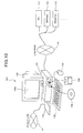
- FIG. 10 is a total structure view of a computer system that executes a data input program according to a fourth embodiment,
- FIG. 11 is a functional block diagram that shows a structure of a main body shown in FIG. 10, and
- FIG. 12A is a view that shows a conventional example of a display object (a screen example) when a slider control is used to input data. FIG. 12B is a view that shows a conventional example of a display object (a screen example) when a color chart is used to input data.
- A data input device, a data input method, and a data input program according to the first embodiment of the present invention will be explained in detail below with reference to the accompanying drawings.
- FIG. 1 is a functional block diagram of a
data input device 10 relating to the first embodiment. FIG. 2 is a flowchart of a data input method relating to the first embodiment. - As shown in FIG. 1, the
data input device 10 is constructed of aninput unit 14, anoutput unit 15, an input-output control unit 16, and acontrol unit 17. Thecontrol unit 17 is constructed of an indicationposition detecting unit 11, an indicationposition changing unit 11 a, a displayposition detecting unit 12, and an inputvalue setting unit 13. The indicationposition detecting unit 11 has a function of detecting an indication position on a display object that is indicated with a mouse pointer that a user operates. The indicationposition changing unit 11 a has a function of optionally changing an indication position that has been once set. - The display
position detecting unit 12 has a function of detecting a display position of a display object with the mouse pointer that the user operates. The inputvalue setting unit 13 has a function of setting a plurality of parameter data input values based on an indication position on a display object and a display position of the display object that have been obtained by the indicationposition detecting unit 11 and the displayposition detecting unit 12 respectively. - The
control section 17 has a controller function of controlling the wholedata input device 10. Theinput unit 14 has an operating function of setting data by operating the display object via the input-output control unit 16. A mouse is used as a pointing device of thisinput unit 14. - The
output unit 15 has a display function of displaying processing results of the indicationposition detecting unit 11, the indicationposition changing unit 11 a, the displayposition detecting unit 12, and the inputvalue setting unit 13 within thecontrol section 17 via the input-output control unit 16. A display screen (CRT) of a personal computer is used as theoutput unit 15. - As shown in FIG. 2, a data input method of the data input device relating to the present invention is broadly constructed of three steps of (1) an indication position detecting step, (2) a display position detecting step, and (3) an input value setting step (step S 201 to step S203). The indication position detecting step is a step of detecting an indication position on a knob that has been indicated by a user. The display position detecting step is a step of detecting a display position on a line that has been moved by clicking the mouse by the user. The input value setting step is a step of setting a plurality of parameter input values (data) based on the indication position and the display position that have been obtained at the indication position detecting step and the display position detecting step respectively.
- The first embodiment of the present invention will be explained in detail below with reference to FIG. 3A and FIG. 3B. FIG. 3A and FIG. 3B show screens of a display object that is displayed on a display. An example that optional color data (R, G, and B) are set in the setting of a desktop environment and an image editing software, like in the explanation shown in FIG. 12 will be described. A mouse will be used as a pointing device.
- FIG. 3A shows a display screen when a user has moved a mouse pointer onto a knob, and clicked the mouse. FIG. 3B shows a display screen when the user has dragged the knob to move it along the line, in the state that the knob has been caught with the mouse pointer without releasing the depressed finger from the mouse. In other words, as shown in FIG. 3A, a
display object 30 is constructed of a part that shows aknob 31, a part that shows aline 32 along which thisknob 31 can move, and areas P1, P2, and P3 in which data is input. - Specifically, it is possible to input (set) data of desired values by clicking the mouse to catch the
knob 31 and also by dragging the knob to move it along theline 32. The input data are stored in the area P1, the area P2, and the area P3 respectively, and are displayed as parameter values respectively. As explained above, according to the first embodiment, it is possible to input three parameters as data with one knob and one line. - In other words, in FIG. 3A, by moving the
mouse pointer 35 to theknob 31 and clicking the mouse, it is possible to calculate input values as data based on an indication position of themouse pointer 35 on theknob 31. The calculated values are displayed in the area P1 and the area P2 respectively. A calculation method will be explained later. Areference number 36 denotes a marker that shows a position indicated with themouse pointer 35. In this example, based on a display of an indication position with themarker 36, it is possible to adjust parameter set values while estimating an indication position on theknob 31 at which desired values can be obtained. - Further, in FIG. 3A, it is possible to change values by dragging the
knob 31 to move it with themouse pointer 35 in a state that the mouse has been clicked and kept depressed with the finger. By dragging, a display screen as shown in FIG. 3B is obtained. On the display screen shown in FIG. 3B, as the display position of theknob 31 on the line has been moved, a value corresponding to this display position of theknob 31 is calculated, and this value is displayed in the area P3. A method of calculating this value corresponding to this display position of theknob 31 is similar to that of the slider control explained in the above conventional technique. Therefore, a detailed explanation of this calculation method will be omitted. - The processing based on an indication position when the mouse pointer has been moved and the mouse has been clicked, in FIG. 3A, will be explained in detail with reference to FIG. 4.
- As shown in FIG. 4, the knob is set with an indication position detecting area PA for optionally specifying an indication position. This indication position detecting area PA is set with an X coordinate in the horizontal direction and a Y coordinate in the vertical direction. The indication position detecting area PA has been provided with a rectangular area that has prescribed sizes of an SX size in the X coordinate direction and an SY size in the Y coordinate direction, with the left top end as the origin in FIG. 4. An X coordinate direction minimum value and a Y coordinate direction minimum value have been set to this origin respectively, and an X coordinate direction maximum value and a Y coordinate direction maximum value have been set to correspond to the SX size and the SY size respectively.
- Specifically, when the mouse has been clicked within this indication position detecting area PA, it is possible to obtain respective coordinates of a coordinate X1 and a coordinate Y1 that specify the indication position. It is possible to obtain the coordinate X1 and the coordinate Y1 by obtaining origin coordinates of the indication position detecting area PA from the display coordinates of the knob on the screen and by calculating a difference between the mouse clicked position (the coordinate X1, the coordinate Y1) and the origin coordinates of the indication position detecting area PA on the screen respectively.
- It is possible to calculate values of P1 and P2 based on the coordinate X1 and the coordinate Y1 obtained above, the minimum values and the maximum values of the X coordinate and the Y coordinate respectively, the SX size and the SY size of the indication position detecting area PA, and the indication position on the
knob 31. Specifically, it is possible to calculate the values based on thefollowing equation 1. In this expression, Xmax represents a maximum value of the X coordinate, Xmin represents a minimum value of the X coordinate, Ymax represents a maximum value of the Y coordinate, and Ymin represents a minimum value of the Y coordinate, respectively. - P1=(Xmax−Xmin)×X1/SX
- P2=(Ymax−Ymin)×Y1/SY (1)
- As explained above, according to the first embodiment of the present invention, it is possible to input a plurality of (three, in this example) parameter data by operating one display object.
- Specifically, it is possible to set three-dimensional values by operating the
knob 31 in one dimension. - While a slider control is employed in the first embodiment like in the conventional example, it is possible to make smaller the display area of the display object by limiting the move of the
knob 31 on the slider control. As shown in FIG. 5, when an indication position on theknob 31 is at point A, the move of theknob 31 is L1, and when an indication position on theknob 31 is at point B, the move of theknob 31 is L2. From the above, it is possible to limit the range of moving the knob between the data. When the range of moving theknob 31 has been limited, it is possible to make small the display area of the display object. Further, along the move of theknob 31, it is also possible to change the shape or length of the knob. - A second embodiment of the present invention will be explained with reference to FIG. 6. Configuration of a data input device relating to the second embodiment is same as the one shown in FIG. 1. As shown in FIG. 6, a
display object 60 is constructed of a part that shows aknob 61 that a user operates, and a part that shows agrid 62 within which theknob 61 can move. An area P1 to an area P4 that show values that are set by operating theknob 61 are provided adjacent to thegrid 62. A display mode of thedisplay object 60 is similar to that of the color chart shown in the conventional example, except that there is no scale. - In FIG. 6, when the mouse has been operated to move the
mouse pointer 35 to theknob 61 and the mouse has been clicked, values are calculated according to the processing of the present invention based on an indication position of themouse pointer 35 on the knob. The calculated values are displayed in the area P1 and the area P2. These values based on the indication position on theknob 61 are calculated based on the calculation method of theequation 1, in a similar manner to that of the first embodiment. - In the second embodiment, a
marker 63 is displayed at the indication position to enable the user to know the position indicated by themouse pointer 35, in a similar manner to that of the first embodiment. The values calculated based on the indication position on theknob 61 are displayed in the area P1 and the area P2, and values corresponding to the display position of theknob 61 on thegrid 62 are displayed in the area P3 and the area P4. The values corresponding to the display position of theknob 61 on thegrid 62 are calculated according to a calculation method similar to that used to calculate values at the indication position on theknob 61. - As information that shows a display position of the
knob 61 on thegrid 62, it is possible to use the indication position of themouse pointer 35. It is also possible to utilize the origin and weighted center of the indication position detecting area PA that have been set to theknob 61. - A data input method relating to the second embodiment will be explained in detail below with reference to a flowchart shown in FIG. 7. First, when a display object for inputting parameter values has been displayed, it is decided whether the mouse has been clicked on the knob of the display object (step S 700). When the mouse has been clicked on the knob (Yes at step S700), a marker is displayed at the indication position of the mouse pointer on the knob (step S701).
- Values are calculated based on the indication position on the knob (step S 702), and values are calculated based on the display position of the knob (step S703). The values are set to the corresponding display areas P1 and P2 based on the indication position and the display position. Specifically, in the slider control shown in the first embodiment, these values are calculated based on the display position of the knob on the line. In the color chart shown in the second embodiment, these values are calculated based on the display position of the knob on the grid. Then, it is decided whether the click has been canceled (step S704).
- When it has been decided that the click has not been cancelled (No at step S 704), it is decided whether the dragging operation has been carried out (step S705). When it has been decided that the dragging operation has been carried out (Yes at step S705), the process returns to step S703. Based on this dragging operation, values are calculated based on the display position of the knob that is displayed at present, and the values that have been displayed so far are changed to the values after the calculation in the corresponding display areas. When it has been decided that the dragging operation has not been carried out (No at step S705), the process returns to step S704 to make decision about whether the click has been cancelled.
- At step S 704, when the click has been cancelled and when an OK button, not shown, has been depressed to confirm values, the values that have been set so far are confirmed as user input parameter values (step S706). Then, the processing ends.
- In the second embodiment, once the mouse has been clicked on the knob, the values calculated based on the indication position of the mouse pointer is made firm. However, these values can be changed. This case will be explained below as a third embodiment. Explanation of the processing of which contents are similar to those of the second embodiment will be omitted, and processing that is different from the processing of the second embodiment will be mainly explained. The processing at step S 700 to step S704 in FIG. 8 is similar to the processing of the second embodiment. In order to change the position (step S800) a processing according to a flowchart shown in FIG. 9 is carried out. As shown in FIG. 9, it is decided whether a SHIFT key has been depressed in a state that the mouse has been clicked on the knob (step S901).
- When it has been decided at step S 901 that the SHIFT key has been depressed (Yes at step S901), the user moves the mouse to move the mouse pointer on the knob. At the time of moving the mouse pointer, the mouse is kept clicked without releasing the finger depressed on the mouse. After moving the mouse, when it has been decided that the depression of the SHIFT key has been cancelled (step S901), the process returns to the processing at step S701 shown in FIG. 8. The
marker 35 is moved to the position on theknob 31 to which themouse pointer 36 has been moved at the time of depressing the SHIFT key, thereby to display thismarker 35. On the other hand, when the depression of the SHIFT key at step S902 has not been cancelled (No at step S902), the mouse is moved continuously (step S903). - Based on the above processing, it is possible to change the position of the knob at which the mouse has been clicked. By changing the position indicated by the user, it is possible to change the value calculated based on the indication position on the knob to a user's desired value. While the SHIFT key has been used to change the indication position of the mouse pointer in the third embodiment, it is also possible to use other keys such as a CTRL key and an ALT key. Further, instead of the key, it is possible to use other button than that used for the clicking that is provided in the mouse, as an alternative of the SHIFT key.
- In other words, any means may be used to indicate a change of a position at which the mouse has been clicked. For example, in the above first to third embodiments, while two values have been calculated based on the indication position on the knob, it is also possible to calculate one value based on a distance from the origin of the X coordinate to the X coordinate of the indication position on the knob. It is also possible to calculate one value based on a distance from the origin of the Y coordinate to the Y coordinate of the indication position on the knob. Alternatively, it is also possible to calculate one value based on a linear distance from the origin to the indication position or the like.
- In this case, a value is calculated by setting a minimum value to the origin and setting a maximum value to a coordinate at which the distance from the origin to this coordinate becomes maximum. According to the above embodiments, it becomes possible to set two values by using one display object when the slider control as explained in the first embodiment is used. In other words, it is possible to set two-dimensional values by operating the knob in one dimension. When the color chart as explained in the second embodiment is used, it becomes possible to set three values by using one display object. It is possible to set three-dimensional values by operating the knob in two dimensions.
- In the first to third embodiments, while the values are calculated according to the
equation 1 by using a position within a display object that has been indicated by themouse pointer 35, the value calculation method is not limited to the calculation method according to theequation 1. It is also possible to use any calculation expression and calculation method when it is possible to input values of more dimensions than dimensions of the operation directions of the display object. For example, in the first to third embodiments, while the display position within the display object and the value to be set are in a proportional relationship, it is also possible to use a calculation expression that gives an inversely proportional relationship. It is also possible to set values to areas obtained by virtually dividing an object into a plurality of small areas, and use values that have been set to the areas indicated by themouse pointer 35 as user's input values. - In the first to third embodiments, while values have been calculated based on the indication position on the knob by using the mouse click operation as a trigger, it is also possible to detect a position of the mouse pointer on the knob, and calculate values by using this detection as a trigger. In this case, not only the click on the mouse on the knob is detected in the flowchart at step S 700 in FIG. 7 and FIG. 8, but also a position of the
mouse pointer 35 on the knob is also detected. When a position of themouse pointer 35 on the knob has been detected, a marker is displayed at the position of themouse pointer 35 at step S701, and values are calculated based on the position of themouse pointer 35 on the knob at step S703. Thereafter, the process returns to step S700 again to detect a position of themouse pointer 35 on the knob. - It is also possible to optionally change the size and the shape of the knob. It is preferable to change the size to a size which facilitates the user to indicate a position with the
mouse pointer 35 and change the shape to a shape which facilitates the user to know input values. The shape of the indication position detecting area PA is not limited to a rectangle, and it is possible to change the shape to follow the shape of the knob. The display of the slider control can be changed to the display of a scroll bar. In this case, it is possible to apply the present invention by using a scroll bar slider that is displayed within the scroll bar as a knob. - As a fourth embodiment, a computer system that executes a data input program that has functions similar to those of the data input device explained in the first to third embodiments will be explained.
- A
computer system 100 that is shown in FIG. 10 and FIG. 11 is constructed of amain body 101, adisplay 102 that displays information such as images on adisplay screen 102 a based on an indication from themain body 101, agraphic board 106, akeyboard 103 from which various information is input to thecomputer system 100, amouse 104 that is used to assign an optional position on thedisplay screen 102 a of thedisplay 102, a LAN interface that is connected to a local area network (LAN) 110 or a wide-area network (WAN), and amodem 105 that is connected to apublic line 107 such as the Internet. - The
LAN 110 connects thecomputer system 100 to other computer system (PC) 111, aserver 112, aprinter 113 or the like. As shown in FIG. 11, themain body 101 is constructed of aCPU 121, aRAM 122, aROM 123, a hard disk drive (HDD) 124, a CD-ROM drive 125, anFD drive 126, an I/O interface 127, and aLAN interface 128. - The
RAM 122 is used to hold data that has been developed so that the data is displayed on the screen of thedisplay 102. The display data that has been developed by theRAM 122 is displayed on the screen of thedisplay 102 via thegraphic board 106. Thekeyboard 103 has a plurality of character keys and number keys, and is used to input various kinds of data. Themouse 104 is used to selectively indicate with a mouse pointer that is displayed on a display screen 103 a of thedisplay 102. - In executing a data input program by the
computer system 100, the data input program is installed on thecomputer system 100. The data input program is stored in a recording medium such as a portable recording medium like a floppy disk (FD) 108, a CD-ROM 109, a DVD disk, an optical magnetic disk, and an IC card, or in a database of theserver 112 that has been connected via the line by utilizing themodem 105 and the LAN interface or in the database of the other computer system (PC) 111. The installed model built-up program is stored in theHDD 124, and is executed by theCPU 121 by utilizing theRAM 122 and theROM 123. - The recording medium includes a portable recording medium such as the CD-
ROM 109, thefloppy disk 108, the DVD disk, the optical magnetic disk, and the IC card, a recording device such as thehard disks 124 that are provided within and outside thecomputer system 100, a database of theserver 112 that holds a data input program of the original installation that has been connected via theLAN 106, theother computer system 111 and its database, and a transmission medium on thepublic line 107. - As explained above, according to the fourth embodiment, the
computer system 100 executes a data input program that realizes a structure of the data input devices explained in the first to third embodiments by software. With this arrangement, it is possible to obtain effects similar to those of the data input devices explained in the first to third embodiments, by utilizing a general computer system. While thecomputer system 100 is shown in the fourth embodiment, any hardware structure can be used if this hardware structure can execute the processing of the data input device according to the present invention. The kind of the computer system is not limited to a personal computer, and it is also possible to use on an information terminal device (PDA) or others. - As explained above, according to the present invention, there is provided a data input device that carries out a data input by operating a display object that has a graphic display and user interface function. The data input device comprises an indication position detecting unit that detects an indication position on a display object that has been indicated with a pointer that a user operates, a display position detecting unit that detects a display position of the display object, and an input value setting unit that sets input values of the user based on the indication position on the display object and the display position of on the display object. It is possible to input a plurality of parameter data by operating one display object. Therefore, there is an effect that it becomes possible to input a plurality of parameter values (data) in a small display area. Further, there is an effect that it becomes possible to improve convenience and operability for a user by preventing the hiding of other display information.
- Although the invention has been described with respect to a specific embodiment for a complete and clear disclosure, the appended claims are not to be thus limited but are to be construed as embodying all modifications and alternative constructions that may occur to one skilled in the art which fairly fall within the basic teaching herein set forth.
Claims (10)
Applications Claiming Priority (2)
| Application Number | Priority Date | Filing Date | Title |
|---|---|---|---|
| JP2002111766A JP3979156B2 (en) | 2002-04-15 | 2002-04-15 | Data input device, method and program |
| JP2002-111766 | 2002-04-15 |
Publications (2)
| Publication Number | Publication Date |
|---|---|
| US20030193474A1 true US20030193474A1 (en) | 2003-10-16 |
| US7446751B2 US7446751B2 (en) | 2008-11-04 |
Family
ID=28786655
Family Applications (1)
| Application Number | Title | Priority Date | Filing Date |
|---|---|---|---|
| US10/285,521 Expired - Fee Related US7446751B2 (en) | 2002-04-15 | 2002-11-01 | Data input device, data input method, and data input program |
Country Status (2)
| Country | Link |
|---|---|
| US (1) | US7446751B2 (en) |
| JP (1) | JP3979156B2 (en) |
Cited By (4)
| Publication number | Priority date | Publication date | Assignee | Title |
|---|---|---|---|---|
| US20110153085A1 (en) * | 2009-12-17 | 2011-06-23 | Whirlpool Corporation | Laundry treating appliance control system |
| US20120218293A1 (en) * | 2009-08-21 | 2012-08-30 | Akihiro Yamasaki | Method, apparatus and program for adjusting parameters on user interface screen |
| WO2016168126A1 (en) * | 2015-04-13 | 2016-10-20 | Microsoft Technology Licensing, Llc | Reducing a number of selectable options on a display |
| US10338792B2 (en) * | 2014-01-06 | 2019-07-02 | Konica Minolta, Inc. | Object stop position control method, action indicating device, and program |
Families Citing this family (3)
| Publication number | Priority date | Publication date | Assignee | Title |
|---|---|---|---|---|
| JP5123354B2 (en) * | 2010-05-28 | 2013-01-23 | 株式会社東芝 | Information processing system and program |
| US8875054B2 (en) * | 2010-07-30 | 2014-10-28 | Apple Inc. | Hybrid knob/slider control |
| US9069452B2 (en) | 2010-12-01 | 2015-06-30 | Apple Inc. | Morphing a user-interface control object |
Citations (11)
| Publication number | Priority date | Publication date | Assignee | Title |
|---|---|---|---|---|
| US5499325A (en) * | 1992-08-20 | 1996-03-12 | International Business Machines Corporation | Brightness controls for visual separation of vector and raster information |
| US5682488A (en) * | 1995-04-03 | 1997-10-28 | International Business Machine Corp. | Variable computer icon for single control of complex software functions executed on a data processing system |
| US5736974A (en) * | 1995-02-17 | 1998-04-07 | International Business Machines Corporation | Method and apparatus for improving visibility and selectability of icons |
| US5872555A (en) * | 1996-10-24 | 1999-02-16 | International Business Machines Corporation | Method and apparatus for customizing colors in a data processing system |
| US5903255A (en) * | 1996-01-30 | 1999-05-11 | Microsoft Corporation | Method and system for selecting a color value using a hexagonal honeycomb |
| US6226010B1 (en) * | 1995-06-16 | 2001-05-01 | Canon Kabushiki Kaisha | Color selection tool |
| US6243096B1 (en) * | 1997-10-17 | 2001-06-05 | Nec Corporation | Instruction input system with changeable cursor |
| US6348936B1 (en) * | 1998-05-28 | 2002-02-19 | Sun Microsystems, Inc. | Method and apparatus for graphical selection of data |
| US6670972B2 (en) * | 2000-09-26 | 2003-12-30 | Oracle International Corporation | User interface |
| US6697079B2 (en) * | 2001-03-15 | 2004-02-24 | Apple Computer, Inc. | Color palette providing cross-platform consistency |
| US6750889B1 (en) * | 2000-09-21 | 2004-06-15 | Hewlett-Packard Development Company, L.P. | User interface apparatus for displaying a range indicator for setting a plurality of target objects |
Family Cites Families (4)
| Publication number | Priority date | Publication date | Assignee | Title |
|---|---|---|---|---|
| JPS63191277A (en) | 1987-02-04 | 1988-08-08 | Sony Corp | Input device for 3-dimensional coordinate |
| JP3240817B2 (en) | 1994-04-07 | 2001-12-25 | 富士通株式会社 | 3D coordinate input method by speed command |
| JPH09198224A (en) * | 1995-11-13 | 1997-07-31 | Internatl Business Mach Corp <Ibm> | Method for designating value within graphical user interface and device therefor |
| JP4080125B2 (en) | 2000-01-21 | 2008-04-23 | 正昭 宮田 | Information processing apparatus and mouse |
-
2002
- 2002-04-15 JP JP2002111766A patent/JP3979156B2/en not_active Expired - Fee Related
- 2002-11-01 US US10/285,521 patent/US7446751B2/en not_active Expired - Fee Related
Patent Citations (11)
| Publication number | Priority date | Publication date | Assignee | Title |
|---|---|---|---|---|
| US5499325A (en) * | 1992-08-20 | 1996-03-12 | International Business Machines Corporation | Brightness controls for visual separation of vector and raster information |
| US5736974A (en) * | 1995-02-17 | 1998-04-07 | International Business Machines Corporation | Method and apparatus for improving visibility and selectability of icons |
| US5682488A (en) * | 1995-04-03 | 1997-10-28 | International Business Machine Corp. | Variable computer icon for single control of complex software functions executed on a data processing system |
| US6226010B1 (en) * | 1995-06-16 | 2001-05-01 | Canon Kabushiki Kaisha | Color selection tool |
| US5903255A (en) * | 1996-01-30 | 1999-05-11 | Microsoft Corporation | Method and system for selecting a color value using a hexagonal honeycomb |
| US5872555A (en) * | 1996-10-24 | 1999-02-16 | International Business Machines Corporation | Method and apparatus for customizing colors in a data processing system |
| US6243096B1 (en) * | 1997-10-17 | 2001-06-05 | Nec Corporation | Instruction input system with changeable cursor |
| US6348936B1 (en) * | 1998-05-28 | 2002-02-19 | Sun Microsystems, Inc. | Method and apparatus for graphical selection of data |
| US6750889B1 (en) * | 2000-09-21 | 2004-06-15 | Hewlett-Packard Development Company, L.P. | User interface apparatus for displaying a range indicator for setting a plurality of target objects |
| US6670972B2 (en) * | 2000-09-26 | 2003-12-30 | Oracle International Corporation | User interface |
| US6697079B2 (en) * | 2001-03-15 | 2004-02-24 | Apple Computer, Inc. | Color palette providing cross-platform consistency |
Cited By (7)
| Publication number | Priority date | Publication date | Assignee | Title |
|---|---|---|---|---|
| US20120218293A1 (en) * | 2009-08-21 | 2012-08-30 | Akihiro Yamasaki | Method, apparatus and program for adjusting parameters on user interface screen |
| US9201570B2 (en) * | 2009-08-21 | 2015-12-01 | Gvbb Holdings S.A.R.L. | Synchronous control system including a master device and a slave device, and synchronous control method for controlling the same |
| US20110153085A1 (en) * | 2009-12-17 | 2011-06-23 | Whirlpool Corporation | Laundry treating appliance control system |
| US8713975B2 (en) | 2009-12-17 | 2014-05-06 | Whirlpool Corporation | Laundry treating appliance control system |
| DE102010036562B4 (en) | 2009-12-17 | 2024-03-14 | Whirlpool Corp. (A Delaware Corp.) | Control system for laundry treatment devices |
| US10338792B2 (en) * | 2014-01-06 | 2019-07-02 | Konica Minolta, Inc. | Object stop position control method, action indicating device, and program |
| WO2016168126A1 (en) * | 2015-04-13 | 2016-10-20 | Microsoft Technology Licensing, Llc | Reducing a number of selectable options on a display |
Also Published As
| Publication number | Publication date |
|---|---|
| US7446751B2 (en) | 2008-11-04 |
| JP2003308147A (en) | 2003-10-31 |
| JP3979156B2 (en) | 2007-09-19 |
Similar Documents
| Publication | Publication Date | Title |
|---|---|---|
| US10852913B2 (en) | Remote hover touch system and method | |
| US7460123B1 (en) | Dynamic control of graphic representations of data | |
| US7190379B2 (en) | Method for resizing and moving an object on a computer screen | |
| US5625827A (en) | Method and system of blueprint document manipulation | |
| EP2332024B1 (en) | Using physical objects in conjunction with an interactive surface | |
| US8972890B2 (en) | Aminated menu bar | |
| US5907850A (en) | Method and system for manipulating construction blueprint documents with hypermedia hotspot reference links from a first construction document to a related secondary construction document | |
| US7451408B2 (en) | Selecting moving objects on a system | |
| US20040263424A1 (en) | Display system and method | |
| US20040212617A1 (en) | User interface having a placement and layout suitable for pen-based computers | |
| US20130069889A1 (en) | Multi-point contacts with pressure data on an interactive surface | |
| US11061529B2 (en) | Generating contextual guides | |
| GB2317798A (en) | Method and apparatus for providing three-dimensional model associativity | |
| US9557828B2 (en) | Input information processing system, input information processing method, program and computer-readable recording medium | |
| JPH0827700B2 (en) | Computer display control system | |
| KR100553671B1 (en) | Method for driving pointing device of computer system | |
| JPH08234913A (en) | Cursor movement controller | |
| CN104024983B (en) | Interaction models for indirect interaction equipment | |
| WO2012055762A1 (en) | A method, computer program and system for multi-desktop management | |
| JP2007018930A (en) | Semiconductor inspection device | |
| US7446751B2 (en) | Data input device, data input method, and data input program | |
| US6961906B2 (en) | Method and system for switching between windows in a multiwindow computer environment | |
| CN1022955C (en) | Three dimensional graphic interface | |
| US6664990B1 (en) | Computer display pointer with alternate hot spots | |
| JPH07220109A (en) | Information processing device/method |
Legal Events
| Date | Code | Title | Description |
|---|---|---|---|
| AS | Assignment |
Owner name: FUJITSU LIMITED, JAPAN Free format text: ASSIGNMENT OF ASSIGNORS INTEREST;ASSIGNOR:YAMAMOTO, ATSUSHI;REEL/FRAME:013451/0579 Effective date: 20021007 |
|
| STCF | Information on status: patent grant |
Free format text: PATENTED CASE |
|
| FEPP | Fee payment procedure |
Free format text: PAYOR NUMBER ASSIGNED (ORIGINAL EVENT CODE: ASPN); ENTITY STATUS OF PATENT OWNER: LARGE ENTITY |
|
| AS | Assignment |
Owner name: APPLE INC.,CALIFORNIA Free format text: ASSIGNMENT OF ASSIGNORS INTEREST;ASSIGNOR:FUJITSU LIMITED;REEL/FRAME:024515/0384 Effective date: 20100308 |
|
| AS | Assignment |
Owner name: RPX CORPORATION, CALIFORNIA Free format text: ASSIGNMENT OF ASSIGNORS INTEREST;ASSIGNOR:APPLE, INC.;REEL/FRAME:024741/0465 Effective date: 20100520 |
|
| FPAY | Fee payment |
Year of fee payment: 4 |
|
| FPAY | Fee payment |
Year of fee payment: 8 |
|
| AS | Assignment |
Owner name: JEFFERIES FINANCE LLC, NEW YORK Free format text: SECURITY INTEREST;ASSIGNOR:RPX CORPORATION;REEL/FRAME:046486/0433 Effective date: 20180619 |
|
| FEPP | Fee payment procedure |
Free format text: MAINTENANCE FEE REMINDER MAILED (ORIGINAL EVENT CODE: REM.); ENTITY STATUS OF PATENT OWNER: LARGE ENTITY |
|
| AS | Assignment |
Owner name: BARINGS FINANCE LLC, AS COLLATERAL AGENT, NORTH CAROLINA Free format text: PATENT SECURITY AGREEMENT;ASSIGNORS:RPX CLEARINGHOUSE LLC;RPX CORPORATION;REEL/FRAME:054198/0029 Effective date: 20201023 Owner name: BARINGS FINANCE LLC, AS COLLATERAL AGENT, NORTH CAROLINA Free format text: PATENT SECURITY AGREEMENT;ASSIGNORS:RPX CLEARINGHOUSE LLC;RPX CORPORATION;REEL/FRAME:054244/0566 Effective date: 20200823 |
|
| AS | Assignment |
Owner name: RPX CORPORATION, CALIFORNIA Free format text: RELEASE BY SECURED PARTY;ASSIGNOR:JEFFERIES FINANCE LLC;REEL/FRAME:054486/0422 Effective date: 20201023 |
|
| LAPS | Lapse for failure to pay maintenance fees |
Free format text: PATENT EXPIRED FOR FAILURE TO PAY MAINTENANCE FEES (ORIGINAL EVENT CODE: EXP.); ENTITY STATUS OF PATENT OWNER: LARGE ENTITY |
|
| STCH | Information on status: patent discontinuation |
Free format text: PATENT EXPIRED DUE TO NONPAYMENT OF MAINTENANCE FEES UNDER 37 CFR 1.362 |
|
| FP | Lapsed due to failure to pay maintenance fee |
Effective date: 20201104 |