US20030193429A1 - Device and method for the detection of buried objects - Google Patents
Device and method for the detection of buried objects Download PDFInfo
- Publication number
- US20030193429A1 US20030193429A1 US10/121,291 US12129102A US2003193429A1 US 20030193429 A1 US20030193429 A1 US 20030193429A1 US 12129102 A US12129102 A US 12129102A US 2003193429 A1 US2003193429 A1 US 2003193429A1
- Authority
- US
- United States
- Prior art keywords
- sensor array
- downward looking
- signals
- looking infrared
- infrared detectors
- Prior art date
- Legal status (The legal status is an assumption and is not a legal conclusion. Google has not performed a legal analysis and makes no representation as to the accuracy of the status listed.)
- Granted
Links
- 238000001514 detection method Methods 0.000 title claims abstract description 20
- 238000000034 method Methods 0.000 title claims abstract description 14
- 230000000149 penetrating effect Effects 0.000 claims abstract description 15
- 230000005855 radiation Effects 0.000 claims description 4
- 239000012141 concentrate Substances 0.000 claims description 3
- 238000013507 mapping Methods 0.000 claims description 2
- 230000000916 dilatatory effect Effects 0.000 claims 1
- 238000010276 construction Methods 0.000 abstract 1
- 238000012423 maintenance Methods 0.000 abstract 1
- 238000010586 diagram Methods 0.000 description 11
- 230000005674 electromagnetic induction Effects 0.000 description 7
- 239000002184 metal Substances 0.000 description 6
- 238000005516 engineering process Methods 0.000 description 5
- 238000005067 remediation Methods 0.000 description 4
- 230000004927 fusion Effects 0.000 description 3
- 230000004048 modification Effects 0.000 description 3
- 238000012986 modification Methods 0.000 description 3
- 230000008901 benefit Effects 0.000 description 2
- 238000006073 displacement reaction Methods 0.000 description 2
- 230000007246 mechanism Effects 0.000 description 2
- 238000012545 processing Methods 0.000 description 2
- PEDCQBHIVMGVHV-UHFFFAOYSA-N Glycerine Chemical compound OCC(O)CO PEDCQBHIVMGVHV-UHFFFAOYSA-N 0.000 description 1
- 238000013476 bayesian approach Methods 0.000 description 1
- 230000008859 change Effects 0.000 description 1
- 230000001010 compromised effect Effects 0.000 description 1
- 230000001419 dependent effect Effects 0.000 description 1
- 238000013461 design Methods 0.000 description 1
- 238000000605 extraction Methods 0.000 description 1
- 239000000463 material Substances 0.000 description 1
- 230000008569 process Effects 0.000 description 1
- 230000009467 reduction Effects 0.000 description 1
- 230000008439 repair process Effects 0.000 description 1
- 230000004044 response Effects 0.000 description 1
- 239000002689 soil Substances 0.000 description 1
Images


Classifications
-
- G—PHYSICS
- G01—MEASURING; TESTING
- G01V—GEOPHYSICS; GRAVITATIONAL MEASUREMENTS; DETECTING MASSES OR OBJECTS; TAGS
- G01V8/00—Prospecting or detecting by optical means
-
- G—PHYSICS
- G01—MEASURING; TESTING
- G01S—RADIO DIRECTION-FINDING; RADIO NAVIGATION; DETERMINING DISTANCE OR VELOCITY BY USE OF RADIO WAVES; LOCATING OR PRESENCE-DETECTING BY USE OF THE REFLECTION OR RERADIATION OF RADIO WAVES; ANALOGOUS ARRANGEMENTS USING OTHER WAVES
- G01S13/00—Systems using the reflection or reradiation of radio waves, e.g. radar systems; Analogous systems using reflection or reradiation of waves whose nature or wavelength is irrelevant or unspecified
- G01S13/86—Combinations of radar systems with non-radar systems, e.g. sonar, direction finder
-
- G—PHYSICS
- G01—MEASURING; TESTING
- G01V—GEOPHYSICS; GRAVITATIONAL MEASUREMENTS; DETECTING MASSES OR OBJECTS; TAGS
- G01V3/00—Electric or magnetic prospecting or detecting; Measuring magnetic field characteristics of the earth, e.g. declination, deviation
- G01V3/12—Electric or magnetic prospecting or detecting; Measuring magnetic field characteristics of the earth, e.g. declination, deviation operating with electromagnetic waves
-
- G—PHYSICS
- G01—MEASURING; TESTING
- G01V—GEOPHYSICS; GRAVITATIONAL MEASUREMENTS; DETECTING MASSES OR OBJECTS; TAGS
- G01V3/00—Electric or magnetic prospecting or detecting; Measuring magnetic field characteristics of the earth, e.g. declination, deviation
- G01V3/15—Electric or magnetic prospecting or detecting; Measuring magnetic field characteristics of the earth, e.g. declination, deviation specially adapted for use during transport, e.g. by a person, vehicle or boat
Definitions
- This invention relates generally to a system and method for detection of buried objects. More particularly, this system and method utilizes down-looking infrared (DLIR) sensors with or without ground penetrating radar (GPR) and metal detectors (MD) to locate landmines buried beneath ground level.
- DLIR down-looking infrared
- GPR ground penetrating radar
- MD metal detectors
- Today landmines have become an enormous problem for both military forces and civilian populations. Unlike the landmines utilized during World War II and before, today's landmines may not necessarily be made of metal that can be easily detected by metal detectors. Very often these landmines may be made of plastic or other materials that are difficult to differentiate from the surrounding soil or other naturally occurring phenomena. Further, in the case of antitank mines, these mines may be buried relatively deep in the to ground, such as six inches or more. These antitank landmines are designed and positioned in the ground so that the weight of a person would not activate the mine. However, the weight of a vehicle would in most cases set off the mine. Of course, setting off such an antitank mine may also be caused by a tractor plowing a field long after the war is over.
- FIG. 1 One such mechanism is illustrated in FIG. 1 and was known as the Close-In Detection (CID) System, developed under the Mine Hunter/Killer (MH/K) advanced technology demonstration program for the United States military by TRW and subcontractors to TRW.
- CID Close-In Detection
- MH/K Mine Hunter/Killer
- the CID System comprises a vehicle 10 on which a sensor array 30 is attached to the front thereof. This sensor array 30 would be mounted to vehicle 10 be hydraulic lifts and would contain metal detectors (MD) as well as ground penetrating radar (GPR).
- MD metal detectors
- GPR ground penetrating radar
- a forward-looking infrared (FLIR) camera 20 would be mounted to the top of the vehicle 10 and aimed to cover a trapezoidal area 50 in front of the vehicle 10 and sensor array 30 .
- the FLIR 20 as well as sensor array 30 would detect objects 40 positioned below the ground 60 .
- the information from both the sensor array 30 and FLIR 20 may be combined to identify objects 40 .
- the design and operation of the CID System is further detailed in a paper presented in April, 2001 at the SPIE AeroSense Conference 4394: Detection & Remediation Technologies for Mines and Minelike Targets VI, by S. Bishop et al. entitled “Improved Close-In Detection for the Mine Hunter/Killer System”, incorporated herein in its entirety by reference.
- FIG. 2 is a top view of the CID System shown in FIG. 1 and also shows the FLIR field 50 , vehicle 10 and sensor array 30 .
- sensor array 30 is shown containing GPR 70 sensors and electromagnetic induction (EMI) coils 80 that act as metal detectors.
- EMI electromagnetic induction
- the CID System shown in FIGS. 1 and 2 has several drawbacks directly related to the FLIR 20 .
- the FLIR 20 is a relatively expensive and complex piece of equipment due to the lens system and IR detectors contained therein.
- the FLIR 20 may cost as much as 50 percent or more of the cost of the vehicle 10 itself.
- repair and replacement of the FLIR 20 camera is also expensive.
- the FLIR 20 camera views the FLIR field 50 in front of sensor array 30 , the unification of the respective images to identify landmines located beneath ground 60 adds another layer of complexity to the system.
- FIGS. 3A, 3B, and 3 C are similar to the CID System shown in FIG. 1 with the exception that difficulties due to the usage of the FLIR 20 are more clearly illustrated.
- FIG. 3A a misalignment of FLIR 20 camera by as little as one degree will create a one foot placement error in the FLIR field 50 that would result in a one foot displacement of any buried objects 40 detected. Therefore, proper calibration of the FLIR 20 camera is absolutely essential for accurate identification of buried objects 40 .
- a military vehicle such as vehicle 10
- off road usage, or simply rough roads will necessitate the frequent realignment of the FLIR 20 camera. This may be particular the case in an active combat area.
- FIG. 3B further illustrates how a rough road having a bump as small as 2 and 1 ⁇ 4 inches will cause a one-foot placement error in the FLIR field 50 .
- a similar sized pothole would also generate a similar displacement error. Since bumps and potholes are frequent occurrences even in the best road systems, the accuracy of the FLIR 20 camera would be compromised.
- FIG. 3C further indicates how a small rise in the road level may also generate a significant placement error. As indicated only a 4 and 1 ⁇ 2 rise can generate a one-foot placement error for objects 40 buried beneath ground 60 .
- FIG. 4 is an illustration of how reflected light from sky 65 may impact FLIR 20 camera.
- a reflection off of object 90 may be generated by sky 65 .
- the object 90 may appear hotter or cooler to the FLIR 20 camera than would otherwise be detected relative to the ground 60 . Therefore, the accuracy of the FLIR 20 camera is also comprised by weather conditions.
- an embodiment having a device for detecting buried objects.
- This device uses a sensor array comprised of discrete downward looking infrared detectors.
- a processor based system is connected to the sensor array to receive and analyze signals received from the downward looking infrared detectors and to generate alarms when the signals analyzed exceed a predetermined threshold indicative of a buried object.
- a further embodiment of the present invention is a device to detect buried objects.
- This device has a sensor array having several downward looking infrared detectors, several EMI coils, and several ground penetrating radar sensors.
- a processor based system is connected to the sensor array to receive and analyze signals received from the downward looking infrared detectors, the EMI coils, and the ground penetrating radar sensors and to generate alarms when the signals analyzed exceed a predetermined threshold indicative of a buried object.
- a still further embodiment of the present invention is a method of detecting buried objects.
- This method receives an image from several downward looking infrared detectors. The image is then passed through a two-dimensional spatial high pass filter and a signal to noise ratio for the image is determined. The signal to noise ratio is compared to a predetermined threshold. The image is dilated and then shrunk to a single point at the center of the image. The single point is mapped to earth coordinates and an alarm is issued when a buried object is detected.
- FIG. 1 is a side view of the Close-In Detection (CID) System vehicle utilizing a sensor array and a forward looking infrared (FLIR) camera;
- CID Close-In Detection
- FLIR forward looking infrared
- FIG. 2 is a top of the CID System vehicle shown in FIG. 1 with its associated FLIR field;
- FIG. 3A is a side view diagram showing placement error due to improper adjustment of the FLIR camera
- FIG. 3B is a side view diagram showing placement error in the FLIR camera due to an uneven road surface
- FIG. 3C is a side view diagram showing placement error in the FLIR camera due to a change in road elevation
- FIG. 4 is an illustration of how weather and cloud patterns may cause reflections that are detected by the FLIR camera.
- FIG. 5 is a side view diagram of a vehicle having a sensor array with a down looking infrared (DLIR) field projected in an example embodiment of the present invention
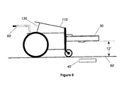
- FIG. 6 is a side view diagram of a cart having a sensor array with a DLIR in an example embodiment of the present invention
- FIG. 7A is a bottom view of an example embodiment of the sensor array in the present invention.
- FIG. 7B is a bottom view of an example embodiment of the sensor array in the present invention.
- FIG. 7C is a bottom view of an example embodiment of the sensor array in the present invention.
- FIG. 8 is a side view of an infrared (IR) sensor utilized in an example embodiment of the present invention.
- FIG. 9 is a systems diagram of an example embodiment of the present invention.
- FIG. 10 is a modular flow diagram of an example embodiment of the present invention.
- FIG. 5 is a side view diagram of a vehicle having a sensor array 30 with a down looking infrared (DLIR) field 100 projected in an example embodiment of the present invention.
- DLIR detectors 140 and 150 are physically located on the underside of the sensor array 30 .
- the sensor array 30 would be permanently affixed to vehicle 10 utilizing permanent supports or hydraulic lifts (not shown).
- the sensor array may also contain GPR 70 sensors as well as EMI coil sensors 80 .
- the sensor array 30 may be connected to a processor-based system 130 and a ground positioning satellite system 210 .
- the DLIR detectors 140 and 150 generating the DLIR field 100 would be used to detect buried objects 40 positioned in the ground 60
- FIG. 6 is a side view diagram of a pushcart 110 having a sensor array 30 with DLIR detectors 140 in an example embodiment of the present invention.
- This push cart 110 is further detailed in CAMPANA et al., “Downward Looking Infrared for Vehicle Mounted Mine Detection”, SPIE AeroSense Conference 4394: Detection & Remediation Technologies for Mines and Minelike Targets VI, Apr. 16, 2001, incorporated in its entirety herein by reference.
- the pushcart 110 would be grasped by handles 120 by an operator (not shown).
- a processor based system 130 such as but not limited to a laptop, would be visible to the operator.
- a sensor array having at least DLIR detectors 140 would be positioned in front of the pushcart 110 so that the DLIR detectors 140 would be approximately 12 inches above ground 60 .
- the sensor array 30 would be utilized to detect buried objects 40 in ground 60 , such as land mines.
- the distance between the sensor array 30 and ground 60 would vary dependent upon the nature of the sensors utilized.
- FIG. 7A is a bottom view of an example embodiment of the sensor array 30 in the present invention.
- the sensor array 30 would contain a row of GPR 70 sensors, EMI coils 80 , and a row of DLIR detectors 140 .
- the sensor array 30 would be mounted as shown in FIGS. 5 and 6. All the foregoing sensors would be connected to the processor based system 130 as illustrated in FIG. 9. In addition all the foregoing sensors would be configured to look down at ground 60 as illustrated in FIGS. 5 and 6.
- FIG. 7B is a bottom view of an example embodiment of the sensor array 30 in the present invention.
- the sensor array 30 illustrated in FIG. 7B is similar to that illustrated in FIG. 7A with the exception that a second row all DLIR detectors 150 is added to FIG. 7B.
- the DLIR detectors 140 and DLIR detectors 150 are offset from each other in order to provide a more complete image of ground 60 . All other features of FIG. 7B remain the same as that of FIG. 7A and will not be discussed further here.
- FIG. 7C is a bottom view of an example embodiment of the sensor array 30 in the present invention.
- Sensor array 30 shown in FIG. 7C, contains only a single row of DLIR detectors 140 . However, as with FIG. 7B, multiple rows of the DLIR detectors may be implemented.
- infrared detectors alone may be utilized to detect mines. All sensors contained in sensor array 30 would, as previously discussed, be fed into a processor-based system 130 as illustrated in FIG. 9.
- FIG. 8 is a side view of an individual infrared (IR) detector 140 utilized in an example embodiment of the present invention.
- This IR detector 140 utilizes a Fresnel lens 160 held in place with holder 175 to focus images received onto infrared detector 170 which is in turn connected to preamp 180 .
- preamplifier 180 is connected to connection line 190 which is in turn connected to processor-based system 130 as shown in FIG. 9.
- the Fresnel lens 160 concentrates infrared radiation onto infrared detector 170 .
- the Fresnel lens 160 therefore substitutes for the complex lens system found in FLIR 20 and is substantially less expensive.
- FIG. 9 is a systems diagram of an example embodiment of the present invention. All components illustrated in FIG. 9 would be contained in either vehicle 10 or pushcart 110 or attached thereto. As indicated, sensor array 30 would be connected to a processor-based system 130 . In addition, a global positioning satellite system (GPSS) 210 or other well-known method of determining location is connected to processor-based system 130 . This is required in order for the vehicle 10 or pushcart 110 to precisely identify the location of any buried objects 40 detected.
- GPSS global positioning satellite system
- FIG. 10 is a modular configuration flow diagram of the software, firmware, and hardware used in the embodiments of the present invention.
- the blocks illustrated in FIG. 10 represent modules, code, code segments, commands, firmware, hardware, instructions and data that are executable by a processor-based system(s) and may be written in a programming language, such as, but not limited, to C++.
- an image is received by the sensor array 30 in block 1000 and passed to block 1010 .
- the image is passed through a two-dimensional spatial high pass filter.
- the purpose of the two-dimensional high-pass spatial filter is to optimize the mine signal in relation to sensor noise and scene clutter.
- the two-dimensional high-pass spatial filter is a zero-mean finite impulse response (FIR) spatial filter, implemented by summing pixels in each of three concentric windows.
- rectifier 1020 receives the signal so that negative contrast targets can be detected and simultaneously passes the signal to a noise/clutter estimator 1030 and divider 1035 .
- the noise/clutter estimator 1030 attempts to estimate the amount of noise contained within the signal.
- the rectified average is equal to the standard deviation times sqrt(2/pi). Therefore, the inverse of this scalar is used to adjust the noise estimate.
- the signal-to-noise ratio can be determined based on the signal received from rectifier 1020 and the noise estimated from the noise/clutter estimator 1030 . Thereafter, the signal received from divider 1035 is compared against a predetermined threshold in block 1040 . The resulting binary threshold-exceedance map is passed to the detection merge section in block 1050 , which first dilates and then shrinks the map down to a single point at the center of the detection cluster.
- a mapping of the detections from the IR detector 140 coordinates (frame, row, column) to earth coordinates (north, east) is done.
- detections that fall within a specified capture radius of a prior detection are used to update the position and other metrics associated with that detection.
- processing proceeds to block 1100 where an alarm or alarms are generated solely from IR detectors 140 or in some combination of GPR 70 and EMI coils 80 .
Landscapes
- Engineering & Computer Science (AREA)
- Remote Sensing (AREA)
- Physics & Mathematics (AREA)
- Life Sciences & Earth Sciences (AREA)
- General Physics & Mathematics (AREA)
- Geophysics (AREA)
- General Life Sciences & Earth Sciences (AREA)
- Radar, Positioning & Navigation (AREA)
- Geology (AREA)
- Environmental & Geological Engineering (AREA)
- Electromagnetism (AREA)
- Computer Networks & Wireless Communication (AREA)
- Radar Systems Or Details Thereof (AREA)
- Traffic Control Systems (AREA)
- Geophysics And Detection Of Objects (AREA)
Abstract
Description
- 1. Field of the Invention
- This invention relates generally to a system and method for detection of buried objects. More particularly, this system and method utilizes down-looking infrared (DLIR) sensors with or without ground penetrating radar (GPR) and metal detectors (MD) to locate landmines buried beneath ground level.
- 2. Discussion of the Related Art
- Today landmines have become an enormous problem for both military forces and civilian populations. Unlike the landmines utilized during World War II and before, today's landmines may not necessarily be made of metal that can be easily detected by metal detectors. Very often these landmines may be made of plastic or other materials that are difficult to differentiate from the surrounding soil or other naturally occurring phenomena. Further, in the case of antitank mines, these mines may be buried relatively deep in the to ground, such as six inches or more. These antitank landmines are designed and positioned in the ground so that the weight of a person would not activate the mine. However, the weight of a vehicle would in most cases set off the mine. Of course, setting off such an antitank mine may also be caused by a tractor plowing a field long after the war is over.
- Therefore, the military and other agencies have long desired a mechanism by which buried landmines may be detected and neutralized. One such mechanism is illustrated in FIG. 1 and was known as the Close-In Detection (CID) System, developed under the Mine Hunter/Killer (MH/K) advanced technology demonstration program for the United States military by TRW and subcontractors to TRW. The CID System comprises a
vehicle 10 on which asensor array 30 is attached to the front thereof. Thissensor array 30 would be mounted tovehicle 10 be hydraulic lifts and would contain metal detectors (MD) as well as ground penetrating radar (GPR). In addition, a forward-looking infrared (FLIR)camera 20 would be mounted to the top of thevehicle 10 and aimed to cover atrapezoidal area 50 in front of thevehicle 10 andsensor array 30. The FLIR 20 as well assensor array 30 would detectobjects 40 positioned below theground 60. The information from both thesensor array 30 and FLIR 20 may be combined to identifyobjects 40. The design and operation of the CID System is further detailed in a paper presented in April, 2001 at the SPIE AeroSense Conference 4394: Detection & Remediation Technologies for Mines and Minelike Targets VI, by S. Bishop et al. entitled “Improved Close-In Detection for the Mine Hunter/Killer System”, incorporated herein in its entirety by reference. - FIG. 2 is a top view of the CID System shown in FIG. 1 and also shows the
FLIR field 50,vehicle 10 andsensor array 30. In addition,sensor array 30 is shown containingGPR 70 sensors and electromagnetic induction (EMI) coils 80 that act as metal detectors. - However, the CID System shown in FIGS. 1 and 2 has several drawbacks directly related to the
FLIR 20. First, the FLIR 20 is a relatively expensive and complex piece of equipment due to the lens system and IR detectors contained therein. The FLIR 20 may cost as much as 50 percent or more of the cost of thevehicle 10 itself. Thus, repair and replacement of theFLIR 20 camera is also expensive. In addition, since theFLIR 20 camera views theFLIR field 50 in front ofsensor array 30, the unification of the respective images to identify landmines located beneathground 60 adds another layer of complexity to the system. - Still further, FIGS. 3A, 3B, and 3C are similar to the CID System shown in FIG. 1 with the exception that difficulties due to the usage of the
FLIR 20 are more clearly illustrated. In FIG. 3A, a misalignment ofFLIR 20 camera by as little as one degree will create a one foot placement error in theFLIR field 50 that would result in a one foot displacement of any buriedobjects 40 detected. Therefore, proper calibration of theFLIR 20 camera is absolutely essential for accurate identification of buriedobjects 40. Of course, in a military vehicle, such asvehicle 10, off road usage, or simply rough roads, will necessitate the frequent realignment of the FLIR 20 camera. This may be particular the case in an active combat area. - FIG. 3B further illustrates how a rough road having a bump as small as 2 and ¼ inches will cause a one-foot placement error in the
FLIR field 50. Of course, a similar sized pothole would also generate a similar displacement error. Since bumps and potholes are frequent occurrences even in the best road systems, the accuracy of theFLIR 20 camera would be compromised. - FIG. 3C further indicates how a small rise in the road level may also generate a significant placement error. As indicated only a 4 and ½ rise can generate a one-foot placement error for
objects 40 buried beneathground 60. - FIG. 4 is an illustration of how reflected light from
sky 65 may impactFLIR 20 camera. Depending upon the position of the sun and cloud patterns insky 65, a reflection off ofobject 90 may be generated bysky 65. Depending on the weather conditions and whether the sun or moon is out, theobject 90 may appear hotter or cooler to theFLIR 20 camera than would otherwise be detected relative to theground 60. Therefore, the accuracy of theFLIR 20 camera is also comprised by weather conditions. - Therefore, what is needed is a device and method that will have the benefits of IR detection of landmines without the high cost of an FLIR camera. Further, these IR detectors should not require repeated or complex adjustments in order to operate properly and should not be affected by road or weather conditions.
- In accordance with the teachings of the present invention an embodiment is disclosed having a device for detecting buried objects. This device uses a sensor array comprised of discrete downward looking infrared detectors. A processor based system is connected to the sensor array to receive and analyze signals received from the downward looking infrared detectors and to generate alarms when the signals analyzed exceed a predetermined threshold indicative of a buried object.
- A further embodiment of the present invention is a device to detect buried objects. This device has a sensor array having several downward looking infrared detectors, several EMI coils, and several ground penetrating radar sensors. A processor based system is connected to the sensor array to receive and analyze signals received from the downward looking infrared detectors, the EMI coils, and the ground penetrating radar sensors and to generate alarms when the signals analyzed exceed a predetermined threshold indicative of a buried object.
- A still further embodiment of the present invention is a method of detecting buried objects. This method receives an image from several downward looking infrared detectors. The image is then passed through a two-dimensional spatial high pass filter and a signal to noise ratio for the image is determined. The signal to noise ratio is compared to a predetermined threshold. The image is dilated and then shrunk to a single point at the center of the image. The single point is mapped to earth coordinates and an alarm is issued when a buried object is detected.
- Additional objects, features and advantages of the present invention will become apparent from the following description and the appended claims when taken in connection with the accompanying drawings.
- The foregoing and a better understanding of the present invention will become apparent from the following detailed description of exemplary embodiments and the claims when read in connection with the accompanying drawings, all forming a part of the disclosure of this invention. While the foregoing and following written and illustrated disclosure focuses on disclosing example embodiments of the invention, it should be clearly understood that the same is by way of illustration and example only and the invention is not limited thereto. The spirit and scope of the present invention are limited only by the terms of the appended claims.
- The following represents brief descriptions of the drawings, wherein:
- FIG. 1 is a side view of the Close-In Detection (CID) System vehicle utilizing a sensor array and a forward looking infrared (FLIR) camera;
- FIG. 2 is a top of the CID System vehicle shown in FIG. 1 with its associated FLIR field;
- FIG. 3A is a side view diagram showing placement error due to improper adjustment of the FLIR camera;
- FIG. 3B is a side view diagram showing placement error in the FLIR camera due to an uneven road surface;
- FIG. 3C is a side view diagram showing placement error in the FLIR camera due to a change in road elevation;
- FIG. 4 is an illustration of how weather and cloud patterns may cause reflections that are detected by the FLIR camera; and
- FIG. 5 is a side view diagram of a vehicle having a sensor array with a down looking infrared (DLIR) field projected in an example embodiment of the present invention;
- FIG. 6 is a side view diagram of a cart having a sensor array with a DLIR in an example embodiment of the present invention;
- FIG. 7A is a bottom view of an example embodiment of the sensor array in the present invention;
- FIG. 7B is a bottom view of an example embodiment of the sensor array in the present invention;
- FIG. 7C is a bottom view of an example embodiment of the sensor array in the present invention;
- FIG. 8 is a side view of an infrared (IR) sensor utilized in an example embodiment of the present invention;
- FIG. 9 is a systems diagram of an example embodiment of the present invention; and
- FIG. 10 is a modular flow diagram of an example embodiment of the present invention.
- Before beginning a detailed description of the subject invention, mention of the following is in order. When appropriate, like reference numerals and characters maybe used to designate identical, corresponding or similar components in differing figure drawings. Further, in the detailed description to follow, exemplary sizes/models/values/ranges may be given, although the present invention is not limited to the same.
- FIG. 5 is a side view diagram of a vehicle having a
sensor array 30 with a down looking infrared (DLIR)field 100 projected in an example embodiment of the present invention.DLIR detectors sensor array 30. Thesensor array 30 would be permanently affixed tovehicle 10 utilizing permanent supports or hydraulic lifts (not shown). As will be discussed further in FIGS. 7A, 7B, and 7C, the sensor array may also containGPR 70 sensors as well asEMI coil sensors 80. By placingDLIR detectors sensor array 30 looking downward to generate DLIR field 100 a significant reduction in cost is realized since aFLIR 20 camera with its associated lenses is no longer required. The precise configuration of theDLIR detectors sensor array 30 may be connected to a processor-basedsystem 130 and a groundpositioning satellite system 210. TheDLIR detectors DLIR field 100 would be used to detect buriedobjects 40 positioned in theground 60 - FIG. 6 is a side view diagram of a
pushcart 110 having asensor array 30 withDLIR detectors 140 in an example embodiment of the present invention. Thispush cart 110 is further detailed in CAMPANA et al., “Downward Looking Infrared for Vehicle Mounted Mine Detection”, SPIE AeroSense Conference 4394: Detection & Remediation Technologies for Mines and Minelike Targets VI, Apr. 16, 2001, incorporated in its entirety herein by reference. Thepushcart 110 would be grasped by handles 120 by an operator (not shown). A processor basedsystem 130, such as but not limited to a laptop, would be visible to the operator. A sensor array having at leastDLIR detectors 140 would be positioned in front of thepushcart 110 so that theDLIR detectors 140 would be approximately 12 inches aboveground 60. As will be discussed in further detailed ahead thesensor array 30 would be utilized to detect buriedobjects 40 inground 60, such as land mines. As would be appreciated by one of ordinary skill in the art the distance between thesensor array 30 andground 60 would vary dependent upon the nature of the sensors utilized. - FIG. 7A is a bottom view of an example embodiment of the
sensor array 30 in the present invention. Thesensor array 30 would contain a row ofGPR 70 sensors, EMI coils 80, and a row ofDLIR detectors 140. Thesensor array 30 would be mounted as shown in FIGS. 5 and 6. All the foregoing sensors would be connected to the processor basedsystem 130 as illustrated in FIG. 9. In addition all the foregoing sensors would be configured to look down atground 60 as illustrated in FIGS. 5 and 6. - FIG. 7B is a bottom view of an example embodiment of the
sensor array 30 in the present invention. Thesensor array 30 illustrated in FIG. 7B is similar to that illustrated in FIG. 7A with the exception that a second row allDLIR detectors 150 is added to FIG. 7B. It should be noted that theDLIR detectors 140 andDLIR detectors 150 are offset from each other in order to provide a more complete image ofground 60. All other features of FIG. 7B remain the same as that of FIG. 7A and will not be discussed further here. - FIG. 7C is a bottom view of an example embodiment of the
sensor array 30 in the present invention.Sensor array 30, shown in FIG. 7C, contains only a single row ofDLIR detectors 140. However, as with FIG. 7B, multiple rows of the DLIR detectors may be implemented. As discussed in McGOVERN et al. “Analysis of IR Signatures of Surface and Buried Anti-Tank Landmines”, SPIE AeroSense Conference 4394: Detection & Remediation Technologies for Mines and Minelike Targets VI, Apr. 16, 2001, incorporated by reference in its entirety herein, infrared detectors alone may be utilized to detect mines. All sensors contained insensor array 30 would, as previously discussed, be fed into a processor-basedsystem 130 as illustrated in FIG. 9. - FIG. 8 is a side view of an individual infrared (IR)
detector 140 utilized in an example embodiment of the present invention. ThisIR detector 140 utilizes aFresnel lens 160 held in place withholder 175 to focus images received ontoinfrared detector 170 which is in turn connected topreamp 180. Inturn preamplifier 180 is connected toconnection line 190 which is in turn connected to processor-basedsystem 130 as shown in FIG. 9. TheFresnel lens 160 concentrates infrared radiation ontoinfrared detector 170. TheFresnel lens 160 therefore substitutes for the complex lens system found inFLIR 20 and is substantially less expensive. - FIG. 9 is a systems diagram of an example embodiment of the present invention. All components illustrated in FIG. 9 would be contained in either
vehicle 10 orpushcart 110 or attached thereto. As indicated,sensor array 30 would be connected to a processor-basedsystem 130. In addition, a global positioning satellite system (GPSS) 210 or other well-known method of determining location is connected to processor-basedsystem 130. This is required in order for thevehicle 10 orpushcart 110 to precisely identify the location of any buriedobjects 40 detected. - FIG. 10 is a modular configuration flow diagram of the software, firmware, and hardware used in the embodiments of the present invention. The blocks illustrated in FIG. 10 represent modules, code, code segments, commands, firmware, hardware, instructions and data that are executable by a processor-based system(s) and may be written in a programming language, such as, but not limited, to C++.
- Still referring to FIG. 10, an image is received by the
sensor array 30 inblock 1000 and passed to block 1010. Inblock 1010 the image is passed through a two-dimensional spatial high pass filter. The purpose of the two-dimensional high-pass spatial filter is to optimize the mine signal in relation to sensor noise and scene clutter. The two-dimensional high-pass spatial filter is a zero-mean finite impulse response (FIR) spatial filter, implemented by summing pixels in each of three concentric windows. Thereafter,rectifier 1020 receives the signal so that negative contrast targets can be detected and simultaneously passes the signal to a noise/clutter estimator 1030 anddivider 1035. The noise/clutter estimator 1030 attempts to estimate the amount of noise contained within the signal. This is done using the average of the rectified, zero-mean filter output in the region indicated. For Gaussian noise, the rectified average is equal to the standard deviation times sqrt(2/pi). Therefore, the inverse of this scalar is used to adjust the noise estimate. The signal-to-noise ratio can be determined based on the signal received fromrectifier 1020 and the noise estimated from the noise/clutter estimator 1030. Thereafter, the signal received fromdivider 1035 is compared against a predetermined threshold inblock 1040. The resulting binary threshold-exceedance map is passed to the detection merge section inblock 1050, which first dilates and then shrinks the map down to a single point at the center of the detection cluster. Thereafter, in block 1060 a mapping of the detections from theIR detector 140 coordinates (frame, row, column) to earth coordinates (north, east) is done. Inblock 1070, detections that fall within a specified capture radius of a prior detection are used to update the position and other metrics associated with that detection. - Still referring to FIG. 10, if
only IR detectors 140 are used insensor array 30 the processing proceeds to block 1100 where an alarm is issued. However, if ground penetrating radar (GPR) and metal detectors (MD) are also used insensor array 30, as illustrated in FIGS. 7A and 7B, then the output fromblock 1070 containing the IR feature extractions and block 1090 containing the GPR and MD features are input into themultisensor fusion block 1080. The fusion of data from different sensors may be accomplished as discussed in APONTE et al., “A Bayesian Approach to Multi-Sensor Fusion for Vehicle Mounted Mine Detection”, SPIE AeroSense Conference 4394: Detection & Remediation Technologies for Mines and Minelike Targets VI, Apr. 16, 2001, and incorporated herein in its entirety. Thereafter, processing proceeds to block 1100 where an alarm or alarms are generated solely fromIR detectors 140 or in some combination ofGPR 70 and EMI coils 80. - Using the embodiments of the present invention it is possible detect buried objects, such as anti-tank landmines, with a high degree of accuracy at a significantly reduced cost. By using down looking infrared detectors it is possible to eliminate the need for a costly FLIR camera and reduce clutter generated by reflections from the sky as well as placement errors due to a rough terrain.
- While we have shown and described only a few examples herein, it is understood that numerous changes and modifications as known to those skilled in the art could be made to the present invention. An example of such a modification would include utilizing multiple rows of
infrared detectors 140 insensor array 30 depicted in FIG. 7C. Also, any processor-basedsystem 130, including but not limited to, a PC, laptop or Palm computer may be used to receive and process the data and displaying the results. Further, any highly accurate means of determining the vehicle's 10 position on the ground may be used in substitute for theGPSS 210. Therefore, we do not wish to be limited to the details shown and described herein, but intend to cover all such changes and modifications as are encompassed by the scope of the appended claims.
Claims (19)
Priority Applications (1)
| Application Number | Priority Date | Filing Date | Title |
|---|---|---|---|
| US10/121,291 US6838671B2 (en) | 2002-04-12 | 2002-04-12 | Device and method for the detection of buried objects |
Applications Claiming Priority (1)
| Application Number | Priority Date | Filing Date | Title |
|---|---|---|---|
| US10/121,291 US6838671B2 (en) | 2002-04-12 | 2002-04-12 | Device and method for the detection of buried objects |
Publications (2)
| Publication Number | Publication Date |
|---|---|
| US20030193429A1 true US20030193429A1 (en) | 2003-10-16 |
| US6838671B2 US6838671B2 (en) | 2005-01-04 |
Family
ID=28790288
Family Applications (1)
| Application Number | Title | Priority Date | Filing Date |
|---|---|---|---|
| US10/121,291 Expired - Lifetime US6838671B2 (en) | 2002-04-12 | 2002-04-12 | Device and method for the detection of buried objects |
Country Status (1)
| Country | Link |
|---|---|
| US (1) | US6838671B2 (en) |
Cited By (28)
| Publication number | Priority date | Publication date | Assignee | Title |
|---|---|---|---|---|
| US20050128125A1 (en) * | 2003-08-28 | 2005-06-16 | Jian Li | Land mine detector |
| WO2005078480A1 (en) * | 2004-02-14 | 2005-08-25 | Robert Bosch Gmbh | Method and measuring instrument for locating objects enclosed in a medium |
| WO2006128087A2 (en) * | 2005-05-27 | 2006-11-30 | Entech Engineering, Inc. | System of subterranean anomaly detection and repair |
| US20060284758A1 (en) * | 2003-08-15 | 2006-12-21 | Gregory Stilwell | Multi-mode landmine detector |
| US20070260378A1 (en) * | 2005-12-05 | 2007-11-08 | Clodfelter James F | Apparatus for detecting subsurface objects with a reach-in arm |
| US20070296955A1 (en) * | 2004-02-14 | 2007-12-27 | Uwe Skultety-Betz | Infrared Localization Device Having a Multiple Sensor Apparatus |
| US20080036644A1 (en) * | 2004-02-14 | 2008-02-14 | Uwe Skultety-Betz | Short-Range Radar Having A Multiple Sensor System For Determining The Location Of Objects Enclosed In A Medium |
| US20090037049A1 (en) * | 2007-07-31 | 2009-02-05 | Clodfelter James F | Damage control system and method for a vehicle-based sensor |
| US7548192B1 (en) * | 2008-02-07 | 2009-06-16 | Fdh Engineering, Inc. | Method of mapping steel reinforcements in concrete foundations |
| US7683821B1 (en) * | 2006-10-25 | 2010-03-23 | Niitek, Inc. | Sensor sweeper for detecting surface and subsurface objects |
| US20100085234A1 (en) * | 2003-08-15 | 2010-04-08 | L-3 Communications Cyterra Corporation | Mine detection |
| US20100097182A1 (en) * | 2008-10-17 | 2010-04-22 | Afshin Niktash | Signal Power Mapping For Detection Of Buried Objects And Other Changes To The RF Environment |
| US20100277397A1 (en) * | 2009-03-03 | 2010-11-04 | L-3 Communications Cyterra Corporation | Detection of surface and buried objects |
| DE102009039602B3 (en) * | 2009-09-01 | 2011-04-07 | Deutsches Zentrum für Luft- und Raumfahrt e.V. | Animal searching and detecting method for use in agricultural field and meadow, involves driving camera by guiding system, and delivering alarm signal when detected animal is determined by pattern recognition algorithms |
| US8040272B1 (en) * | 2007-04-20 | 2011-10-18 | Niitek Inc. | Leading and lagging aperture for linear ground penetrating radar array |
| DE102010045084A1 (en) * | 2010-09-13 | 2012-03-15 | Rheinmetall Landsysteme Gmbh | Combined ground radar and metal detector |
| US20120092206A1 (en) * | 2010-08-20 | 2012-04-19 | Etebari Ali | Metal detector and ground-penetrating radar hybrid head and manufacturing method thereof |
| US8258450B1 (en) * | 2008-06-26 | 2012-09-04 | University Of South Florida | Physical and chemical integrated flow imaging device |
| US20130082862A1 (en) * | 2010-08-26 | 2013-04-04 | David W. Paglieroni | Radar signal pre-processing to suppress surface bounce and multipath |
| US20130113648A1 (en) * | 2011-09-30 | 2013-05-09 | L-3 Communications Cyterra Corporation | Sensor head |
| US20130182167A1 (en) * | 2011-07-15 | 2013-07-18 | Hilti Aktiengesellschaft | Method and device for detecting an object in a substrate |
| US8842035B2 (en) | 2010-04-08 | 2014-09-23 | L-3 Communications Security And Detection Systems, Inc. | Sensor head |
| EP1717606A3 (en) * | 2005-04-26 | 2015-06-10 | HILTI Aktiengesellschaft | Detector for embedded oblong objects |
| US20160012704A1 (en) * | 2014-05-16 | 2016-01-14 | Roke Manor Research Limited | Object Detector and Method |
| EP3245507A4 (en) * | 2015-01-15 | 2018-04-04 | Transtech Systems, Inc. | Measurement and monitoring of physical properties of material under test (mut) from a vehicle |
| US10031251B2 (en) | 2012-10-04 | 2018-07-24 | Chemring Sensors And Electronic Systems, Inc. | Shieldings for metal detector heads and manufacturing methods thereof |
| US20190049570A1 (en) * | 2016-02-10 | 2019-02-14 | Carrier Corporation | Presence detection system |
| JP2019100700A (en) * | 2017-11-28 | 2019-06-24 | 日本電信電話株式会社 | Electromagnetic wave imaging device |
Families Citing this family (11)
| Publication number | Priority date | Publication date | Assignee | Title |
|---|---|---|---|---|
| DE10215220B4 (en) * | 2002-04-06 | 2006-09-07 | Rheinmetall Landsysteme Gmbh | Mine sweeping and clearing system for land mines |
| US7109910B1 (en) * | 2002-09-06 | 2006-09-19 | L-3 Communications Cyterra Corporation | Mine detection using radar vibrometer |
| EP1556895A4 (en) * | 2002-10-08 | 2009-12-30 | Chippac Inc | Semiconductor stacked multi-package module having inverted second package |
| DE10319560A1 (en) * | 2003-04-24 | 2004-11-25 | Deutsches Zentrum für Luft- und Raumfahrt e.V. | Mobile remote detection device and method for methane gas accumulation |
| US7467810B2 (en) * | 2004-07-07 | 2008-12-23 | Sensors & Software Inc. | Apparatus for transporting a sensor |
| US20060213359A1 (en) * | 2005-03-25 | 2006-09-28 | Anthony Vitale | IMS Intelligent Management System, LLC, A W.E.C. COMPANY conceived the idea embodied in The LYNX UGV Unmanned Ground Vehicle. The LYNX Unmanned Ground Vehicle (UGV) is a remotely operated autonomous robotic platform outfitted with multiple sensors, technologically advanced equipment, and global communication systems. |
| US7982657B2 (en) | 2009-11-17 | 2011-07-19 | Geophysical Survey Systems, Inc. | Ultra-wideband radar waveform calibration for measurements of a heterogeneous material |
| US8115667B2 (en) * | 2009-11-17 | 2012-02-14 | Geophysical Survey Systems, Inc. | Highway speed ground penetrating radar system utilizing air-launched antenna and method of use |
| WO2012021923A1 (en) * | 2010-08-16 | 2012-02-23 | Groundprobe Pty Ltd | Work area monitor |
| US8917199B2 (en) | 2011-04-13 | 2014-12-23 | Raytheon Company | Subterranean image generating device and associated method |
| KR102412896B1 (en) | 2014-12-18 | 2022-06-24 | 삼성전자 주식회사 | Method and apparatus for supporting facility control of terminal |
Citations (7)
| Publication number | Priority date | Publication date | Assignee | Title |
|---|---|---|---|---|
| US5712441A (en) * | 1995-04-20 | 1998-01-27 | Firma Wegmann & Co. | Land-mine search-and-removal device mounted on a vehicle, especially a military tank, and method of locating and destroying such mines with such a device |
| US5844603A (en) * | 1994-09-21 | 1998-12-01 | Kabushiki Kaisha Toshiba | Image data processing apparatus having functions of dividing the image data, and method of processing image data |
| US5903680A (en) * | 1996-02-05 | 1999-05-11 | U.S. Philips Corporation | Image data recursive noise filter with reduced temporal filtering of higher spatial frequencies |
| US6026135A (en) * | 1997-04-04 | 2000-02-15 | Her Majesty The Queen In Right Of Canada, As Represented By The Minister Of National Defence Of Her Majesty's Canadian Government | Multisensor vehicle-mounted mine detector |
| US6341551B1 (en) * | 2001-02-26 | 2002-01-29 | William G. Comeyne | Land mine hunter killer technique |
| US6417797B1 (en) * | 1998-07-14 | 2002-07-09 | Cirrus Logic, Inc. | System for A multi-purpose portable imaging device and methods for using same |
| US6493612B1 (en) * | 1998-12-18 | 2002-12-10 | Dyson Limited | Sensors arrangement |
-
2002
- 2002-04-12 US US10/121,291 patent/US6838671B2/en not_active Expired - Lifetime
Patent Citations (7)
| Publication number | Priority date | Publication date | Assignee | Title |
|---|---|---|---|---|
| US5844603A (en) * | 1994-09-21 | 1998-12-01 | Kabushiki Kaisha Toshiba | Image data processing apparatus having functions of dividing the image data, and method of processing image data |
| US5712441A (en) * | 1995-04-20 | 1998-01-27 | Firma Wegmann & Co. | Land-mine search-and-removal device mounted on a vehicle, especially a military tank, and method of locating and destroying such mines with such a device |
| US5903680A (en) * | 1996-02-05 | 1999-05-11 | U.S. Philips Corporation | Image data recursive noise filter with reduced temporal filtering of higher spatial frequencies |
| US6026135A (en) * | 1997-04-04 | 2000-02-15 | Her Majesty The Queen In Right Of Canada, As Represented By The Minister Of National Defence Of Her Majesty's Canadian Government | Multisensor vehicle-mounted mine detector |
| US6417797B1 (en) * | 1998-07-14 | 2002-07-09 | Cirrus Logic, Inc. | System for A multi-purpose portable imaging device and methods for using same |
| US6493612B1 (en) * | 1998-12-18 | 2002-12-10 | Dyson Limited | Sensors arrangement |
| US6341551B1 (en) * | 2001-02-26 | 2002-01-29 | William G. Comeyne | Land mine hunter killer technique |
Cited By (50)
| Publication number | Priority date | Publication date | Assignee | Title |
|---|---|---|---|---|
| US7310060B2 (en) * | 2003-08-15 | 2007-12-18 | L-3 Communications Cyterra Corporation | Multi-mode landmine detector |
| US8174429B2 (en) | 2003-08-15 | 2012-05-08 | L-3 Communications Cyterra Corporation | Mine detection |
| US20060284758A1 (en) * | 2003-08-15 | 2006-12-21 | Gregory Stilwell | Multi-mode landmine detector |
| US20100085234A1 (en) * | 2003-08-15 | 2010-04-08 | L-3 Communications Cyterra Corporation | Mine detection |
| US7173560B2 (en) * | 2003-08-28 | 2007-02-06 | University Of Florida Research Foundation, Inc. | Land mine detector |
| US20050128125A1 (en) * | 2003-08-28 | 2005-06-16 | Jian Li | Land mine detector |
| WO2005078480A1 (en) * | 2004-02-14 | 2005-08-25 | Robert Bosch Gmbh | Method and measuring instrument for locating objects enclosed in a medium |
| US8546759B2 (en) * | 2004-02-14 | 2013-10-01 | Robert Bosch Gmbh | Infrared localization device having a multiple sensor apparatus |
| US7956794B2 (en) * | 2004-02-14 | 2011-06-07 | Robert Bosch Gmbh | Short-range radar having a multiple sensor system for determining the location of objects enclosed in a medium |
| US20070296955A1 (en) * | 2004-02-14 | 2007-12-27 | Uwe Skultety-Betz | Infrared Localization Device Having a Multiple Sensor Apparatus |
| US20080036644A1 (en) * | 2004-02-14 | 2008-02-14 | Uwe Skultety-Betz | Short-Range Radar Having A Multiple Sensor System For Determining The Location Of Objects Enclosed In A Medium |
| CN100447581C (en) * | 2004-02-14 | 2008-12-31 | 罗伯特·博世有限公司 | Method and measuring instrument for locating objects enclosed in a medium |
| EP1717606A3 (en) * | 2005-04-26 | 2015-06-10 | HILTI Aktiengesellschaft | Detector for embedded oblong objects |
| US7218267B1 (en) * | 2005-05-27 | 2007-05-15 | Weil Gary J | System of subterranean anomaly detection and repair using infrared thermography and ground penetrating radar |
| WO2006128087A2 (en) * | 2005-05-27 | 2006-11-30 | Entech Engineering, Inc. | System of subterranean anomaly detection and repair |
| WO2006128087A3 (en) * | 2005-05-27 | 2007-03-22 | Entech Eng Inc | System of subterranean anomaly detection and repair |
| US20070090989A1 (en) * | 2005-05-27 | 2007-04-26 | En Tech Engineering, Inc. | System of subterranean anomaly detection and repair using infrared thermography and ground penetrating radar |
| US20070260378A1 (en) * | 2005-12-05 | 2007-11-08 | Clodfelter James F | Apparatus for detecting subsurface objects with a reach-in arm |
| US8374754B2 (en) | 2005-12-05 | 2013-02-12 | Niitek, Inc. | Apparatus for detecting subsurface objects with a reach-in arm |
| US7683821B1 (en) * | 2006-10-25 | 2010-03-23 | Niitek, Inc. | Sensor sweeper for detecting surface and subsurface objects |
| US8040272B1 (en) * | 2007-04-20 | 2011-10-18 | Niitek Inc. | Leading and lagging aperture for linear ground penetrating radar array |
| US8140217B2 (en) | 2007-07-31 | 2012-03-20 | Niitek, Inc. | Damage control system and method for a vehicle-based sensor |
| US20090037049A1 (en) * | 2007-07-31 | 2009-02-05 | Clodfelter James F | Damage control system and method for a vehicle-based sensor |
| US7548192B1 (en) * | 2008-02-07 | 2009-06-16 | Fdh Engineering, Inc. | Method of mapping steel reinforcements in concrete foundations |
| US8258450B1 (en) * | 2008-06-26 | 2012-09-04 | University Of South Florida | Physical and chemical integrated flow imaging device |
| US20100097182A1 (en) * | 2008-10-17 | 2010-04-22 | Afshin Niktash | Signal Power Mapping For Detection Of Buried Objects And Other Changes To The RF Environment |
| US8604911B2 (en) * | 2008-10-17 | 2013-12-10 | Tialinx, Inc. | Signal power mapping for detection of buried objects and other changes to the RF environment |
| US20100277358A1 (en) * | 2009-03-03 | 2010-11-04 | L-3 Communications Cyterra Corporation | Detection of surface and buried objects |
| US20100277397A1 (en) * | 2009-03-03 | 2010-11-04 | L-3 Communications Cyterra Corporation | Detection of surface and buried objects |
| DE102009039602B3 (en) * | 2009-09-01 | 2011-04-07 | Deutsches Zentrum für Luft- und Raumfahrt e.V. | Animal searching and detecting method for use in agricultural field and meadow, involves driving camera by guiding system, and delivering alarm signal when detected animal is determined by pattern recognition algorithms |
| US8842035B2 (en) | 2010-04-08 | 2014-09-23 | L-3 Communications Security And Detection Systems, Inc. | Sensor head |
| US10082572B2 (en) | 2010-04-08 | 2018-09-25 | L-3 Communications Security And Detection Systems, Inc. | Sensor head |
| US9753122B2 (en) | 2010-04-08 | 2017-09-05 | L-3 Communications Security And Detection Systems, Inc. | Sensor head |
| US20120092206A1 (en) * | 2010-08-20 | 2012-04-19 | Etebari Ali | Metal detector and ground-penetrating radar hybrid head and manufacturing method thereof |
| US8854247B2 (en) * | 2010-08-20 | 2014-10-07 | Niitek, Inc. | Metal detector and ground-penetrating radar hybrid head and manufacturing method thereof |
| US9239382B2 (en) | 2010-08-26 | 2016-01-19 | Lawrence Livermore National Security, Llc | Attribute and topology based change detection in a constellation of previously detected objects |
| US20130082862A1 (en) * | 2010-08-26 | 2013-04-04 | David W. Paglieroni | Radar signal pre-processing to suppress surface bounce and multipath |
| US8618976B2 (en) * | 2010-08-26 | 2013-12-31 | Lawrence Livermore National Security, Llc | Radar signal pre-processing to suppress surface bounce and multipath |
| DE102010045084A1 (en) * | 2010-09-13 | 2012-03-15 | Rheinmetall Landsysteme Gmbh | Combined ground radar and metal detector |
| US20130182167A1 (en) * | 2011-07-15 | 2013-07-18 | Hilti Aktiengesellschaft | Method and device for detecting an object in a substrate |
| US9398224B2 (en) * | 2011-07-15 | 2016-07-19 | Hilti Aktiengesellschaft | Method and device for detecting an object in a substrate |
| US20130113648A1 (en) * | 2011-09-30 | 2013-05-09 | L-3 Communications Cyterra Corporation | Sensor head |
| US10605945B2 (en) | 2012-10-04 | 2020-03-31 | Chemring Sensors And Electronic Systems, Inc. | Shieldings for metal detector heads and manufacturing methods thereof |
| US10031251B2 (en) | 2012-10-04 | 2018-07-24 | Chemring Sensors And Electronic Systems, Inc. | Shieldings for metal detector heads and manufacturing methods thereof |
| US20160012704A1 (en) * | 2014-05-16 | 2016-01-14 | Roke Manor Research Limited | Object Detector and Method |
| EP3245507A4 (en) * | 2015-01-15 | 2018-04-04 | Transtech Systems, Inc. | Measurement and monitoring of physical properties of material under test (mut) from a vehicle |
| US10739287B2 (en) | 2015-01-15 | 2020-08-11 | Transtech Systems, Inc. | Measurement and monitoring of physical properties of material under test (MUT) from a vehicle |
| US20190049570A1 (en) * | 2016-02-10 | 2019-02-14 | Carrier Corporation | Presence detection system |
| US11079482B2 (en) * | 2016-02-10 | 2021-08-03 | Carrier Corporation | Presence detection system |
| JP2019100700A (en) * | 2017-11-28 | 2019-06-24 | 日本電信電話株式会社 | Electromagnetic wave imaging device |
Also Published As
| Publication number | Publication date |
|---|---|
| US6838671B2 (en) | 2005-01-04 |
Similar Documents
| Publication | Publication Date | Title |
|---|---|---|
| US6838671B2 (en) | Device and method for the detection of buried objects | |
| US20240069172A1 (en) | Method of Providing Interference Reduction and a Dynamic Region of Interest in a LIDAR System | |
| JP6533619B2 (en) | Sensor calibration system | |
| US7027615B2 (en) | Vision-based highway overhead structure detection system | |
| US7479918B2 (en) | Vehicle-mounted ultra-wideband radar systems and methods | |
| US8896701B2 (en) | Infrared concealed object detection enhanced with closed-loop control of illumination by.mmw energy | |
| Siegel | Land mine detection | |
| EP2941735A1 (en) | Image processing | |
| Torrione et al. | Application of the LMC algorithm to anomaly detection using the Wichmann/NIITEK ground-penetrating radar | |
| McFee et al. | Multisensor vehicle-mounted teleoperated mine detector with data fusion | |
| Jin et al. | Multi-region scene matching based localisation for autonomous vision navigation of UAVs | |
| Yoneda et al. | Simultaneous state recognition for multiple traffic signals on urban road | |
| US20050110496A1 (en) | Interleaved magnetometry and pulsed electromagnetic detection of underground objects | |
| Cremer et al. | Comparison of vehicle-mounted forward-looking polarimetric infrared and downward-looking infrared sensors for landmine detection | |
| US20060091286A1 (en) | Active electro-optical device for detecting obstacles, in particular for autonomous navigation | |
| Faust* et al. | Canadian teleoperated landmine detection systems. Part I: The improved landmine detection project | |
| US20200150228A1 (en) | Method of Providing Interference Reduction and a Dynamic Region of Interest in a LIDAR System | |
| Ratto et al. | Integration of lidar with the NIITEK GPR for improved performance on rough terrain | |
| Cremer et al. | Processing of polarimetric infrared images for landmine detection | |
| WO2005069197A1 (en) | A method and system for adaptive target detection | |
| Prado et al. | Multi-sensor and multi-platform data fusion for buried objects detection and localization | |
| EP2752788A1 (en) | Fusion of multi-spectral and range image data | |
| Garriott et al. | Multisensor system for mine detection | |
| Gu et al. | Correction of vehicle positioning error using 3D-map-GNSS and vision-based road marking detection | |
| Bishop et al. | Improved close-in detection for the mine hunter/killer system |
Legal Events
| Date | Code | Title | Description |
|---|---|---|---|
| AS | Assignment |
Owner name: TRW INC., CALIFORNIA Free format text: ASSIGNMENT OF ASSIGNORS INTEREST;ASSIGNORS:CAMPANA, STEPHAN B.;TERRILL, CONRAD W.;REEL/FRAME:012798/0937 Effective date: 20020408 |
|
| AS | Assignment |
Owner name: NORTHROP GRUMMAN CORPORATION, CALIFORNIA Free format text: ASSIGNMENT OF ASSIGNORS INTEREST;ASSIGNOR:TRW, INC. N/K/A NORTHROP GRUMMAN SPACE AND MISSION SYSTEMS CORPORATION, AN OHIO CORPORATION;REEL/FRAME:013751/0849 Effective date: 20030122 Owner name: NORTHROP GRUMMAN CORPORATION,CALIFORNIA Free format text: ASSIGNMENT OF ASSIGNORS INTEREST;ASSIGNOR:TRW, INC. N/K/A NORTHROP GRUMMAN SPACE AND MISSION SYSTEMS CORPORATION, AN OHIO CORPORATION;REEL/FRAME:013751/0849 Effective date: 20030122 |
|
| STCF | Information on status: patent grant |
Free format text: PATENTED CASE |
|
| CC | Certificate of correction | ||
| FEPP | Fee payment procedure |
Free format text: PAYOR NUMBER ASSIGNED (ORIGINAL EVENT CODE: ASPN); ENTITY STATUS OF PATENT OWNER: LARGE ENTITY |
|
| FPAY | Fee payment |
Year of fee payment: 4 |
|
| AS | Assignment |
Owner name: NORTHROP GRUMMAN SPACE & MISSION SYSTEMS CORP.,CAL Free format text: ASSIGNMENT OF ASSIGNORS INTEREST;ASSIGNOR:NORTHROP GRUMMAN CORPORTION;REEL/FRAME:023699/0551 Effective date: 20091125 Owner name: NORTHROP GRUMMAN SPACE & MISSION SYSTEMS CORP., CA Free format text: ASSIGNMENT OF ASSIGNORS INTEREST;ASSIGNOR:NORTHROP GRUMMAN CORPORTION;REEL/FRAME:023699/0551 Effective date: 20091125 |
|
| AS | Assignment |
Owner name: NORTHROP GRUMMAN SYSTEMS CORPORATION,CALIFORNIA Free format text: ASSIGNMENT OF ASSIGNORS INTEREST;ASSIGNOR:NORTHROP GRUMMAN SPACE & MISSION SYSTEMS CORP.;REEL/FRAME:023915/0446 Effective date: 20091210 Owner name: NORTHROP GRUMMAN SYSTEMS CORPORATION, CALIFORNIA Free format text: ASSIGNMENT OF ASSIGNORS INTEREST;ASSIGNOR:NORTHROP GRUMMAN SPACE & MISSION SYSTEMS CORP.;REEL/FRAME:023915/0446 Effective date: 20091210 |
|
| FPAY | Fee payment |
Year of fee payment: 8 |
|
| FPAY | Fee payment |
Year of fee payment: 12 |