US1859901A - Extruding apparatus - Google Patents
Extruding apparatus Download PDFInfo
- Publication number
- US1859901A US1859901A US441791A US44179130A US1859901A US 1859901 A US1859901 A US 1859901A US 441791 A US441791 A US 441791A US 44179130 A US44179130 A US 44179130A US 1859901 A US1859901 A US 1859901A
- Authority
- US
- United States
- Prior art keywords
- conductor
- die
- extruding
- insulation
- core
- Prior art date
- Legal status (The legal status is an assumption and is not a legal conclusion. Google has not performed a legal analysis and makes no representation as to the accuracy of the status listed.)
- Expired - Lifetime
Links
Images
Classifications
-
- B—PERFORMING OPERATIONS; TRANSPORTING
- B29—WORKING OF PLASTICS; WORKING OF SUBSTANCES IN A PLASTIC STATE IN GENERAL
- B29C—SHAPING OR JOINING OF PLASTICS; SHAPING OF MATERIAL IN A PLASTIC STATE, NOT OTHERWISE PROVIDED FOR; AFTER-TREATMENT OF THE SHAPED PRODUCTS, e.g. REPAIRING
- B29C48/00—Extrusion moulding, i.e. expressing the moulding material through a die or nozzle which imparts the desired form; Apparatus therefor
- B29C48/25—Component parts, details or accessories; Auxiliary operations
- B29C48/30—Extrusion nozzles or dies
- B29C48/32—Extrusion nozzles or dies with annular openings, e.g. for forming tubular articles
- B29C48/34—Cross-head annular extrusion nozzles, i.e. for simultaneously receiving moulding material and the preform to be coated
-
- B—PERFORMING OPERATIONS; TRANSPORTING
- B29—WORKING OF PLASTICS; WORKING OF SUBSTANCES IN A PLASTIC STATE IN GENERAL
- B29C—SHAPING OR JOINING OF PLASTICS; SHAPING OF MATERIAL IN A PLASTIC STATE, NOT OTHERWISE PROVIDED FOR; AFTER-TREATMENT OF THE SHAPED PRODUCTS, e.g. REPAIRING
- B29C48/00—Extrusion moulding, i.e. expressing the moulding material through a die or nozzle which imparts the desired form; Apparatus therefor
- B29C48/03—Extrusion moulding, i.e. expressing the moulding material through a die or nozzle which imparts the desired form; Apparatus therefor characterised by the shape of the extruded material at extrusion
- B29C48/06—Rod-shaped
-
- B—PERFORMING OPERATIONS; TRANSPORTING
- B29—WORKING OF PLASTICS; WORKING OF SUBSTANCES IN A PLASTIC STATE IN GENERAL
- B29C—SHAPING OR JOINING OF PLASTICS; SHAPING OF MATERIAL IN A PLASTIC STATE, NOT OTHERWISE PROVIDED FOR; AFTER-TREATMENT OF THE SHAPED PRODUCTS, e.g. REPAIRING
- B29C48/00—Extrusion moulding, i.e. expressing the moulding material through a die or nozzle which imparts the desired form; Apparatus therefor
- B29C48/03—Extrusion moulding, i.e. expressing the moulding material through a die or nozzle which imparts the desired form; Apparatus therefor characterised by the shape of the extruded material at extrusion
- B29C48/05—Filamentary, e.g. strands
-
- B—PERFORMING OPERATIONS; TRANSPORTING
- B29—WORKING OF PLASTICS; WORKING OF SUBSTANCES IN A PLASTIC STATE IN GENERAL
- B29C—SHAPING OR JOINING OF PLASTICS; SHAPING OF MATERIAL IN A PLASTIC STATE, NOT OTHERWISE PROVIDED FOR; AFTER-TREATMENT OF THE SHAPED PRODUCTS, e.g. REPAIRING
- B29C48/00—Extrusion moulding, i.e. expressing the moulding material through a die or nozzle which imparts the desired form; Apparatus therefor
- B29C48/03—Extrusion moulding, i.e. expressing the moulding material through a die or nozzle which imparts the desired form; Apparatus therefor characterised by the shape of the extruded material at extrusion
- B29C48/09—Articles with cross-sections having partially or fully enclosed cavities, e.g. pipes or channels
Definitions
- This Vinvention relates to extruding apparatus for extruding insulating material upon cores and moreV particularly to improvements in eXtruding devices for applying insulating material in a plurality of layers.
- t0 pass a core through a plurality of die members of different diameters which are coaxially mounted together with a guide member for the core.
- a tubular member together with the die lmembers has been provided as a guide which may be removable from the apparatus for adjustment purposes.
- apparatus as heretofore employed a bending of the core after it passes out of the guide member and before it arrives at the last die member causes the coating material to be eccentrically applied.
- Y c Y In accordance with the present invention the several die members are arranged with their exit orifices very nearly in the same plane taken transversely of the core.
- the distance between the exit oriflces of the first and third of three die members are arranged to lie in two planes not inexcess of about l0 to 15 ⁇ m. m. apart.
- the pressure .egualizing @material may applying apparatus Th ,iI,lsulatingfilate-v in theconductor tasA it issues :fromythe .op'en-k ing ⁇ 1Y0-Lor asidewisejbending et "the part .out-. side fof the-opening.
- the tube 3 is made adjustable with respect to vtheother elements of the extruding head so that it may be moved to a position to give the best results because it specially desirable to cause the irst'layer of y insulating compound to cover 4the pressure equalizing substance in a continu-ous and uniform manner.
- thetube 3 may likewise be made adjustable.
- the parts maybe assembled by bolts or rivets passing through the studs 12 and holding the separat-ors 7 8 and 9 rigidly in posiY tion. Any bolt or rivet head extending through the right-hand end of the separator 8 should be smoothly finished to conform to the surface -of the separator. As shown in Fig. 2. the distancebetween the exit end of the guiding block lland the exit end of the sizing die 9 is shown to be about 10 to 1,5
- An extrusion die for applying a plu-l rality of layers vof plastic insulation such as gutta percha to a conductor in which the die comprises several parts having coaxial exit orifices, the exit orifices of the several partsk being arranged so nearly inthesame-plane that the distance between the irst and the last thereof is not greater than the thickness Yof 'the insulation applied to .the conductor whereby abend inthe conductor as it passes through the die willnotresult in eccentric application of the plasticy insulation.
Description
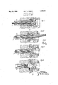
Y May 24, 1932. s: wf A, TREBEs EXTRUDING APPARATUS Filed April 5, 1930 M 4 J 6 3 q W Z Q 4 @i 3 1 m/ 5 v LN /2 5 3 N l N/ by if? MW.
Patented May *24,1932Y f. 'BRU-No M. A. TREIzEs, or BERWYN, ILLINOIS, AssIGNoR To BELL ySaurier'HomeLABonaa- ToRIEs, INCORPORATED, or NEW YORIQN. Y., A1coBi?pRA'J-ION or jyortgzf"f` EXTRUDING ArPAItA'IjUs j j Application med April 5, 1930, serieu No. 441,791, and in :Greatjmitain' septembern, .1929. l
This Vinvention relates to extruding apparatus for extruding insulating material upon cores and moreV particularly to improvements in eXtruding devices for applying insulating material in a plurality of layers.
It has been heretofore proposed to "form several layers of material from a core by passing a core through two dies of different diameters. Y
It-has also been proposed t0 pass a core through a plurality of die members of different diameters Which are coaxially mounted together with a guide member for the core. In such apparatus' a tubular member together with the die lmembers has been provided as a guide which may be removable from the apparatus for adjustment purposes. In apparatus as heretofore employed a bending of the core after it passes out of the guide member and before it arrives at the last die member causes the coating material to be eccentrically applied. Y c Y In accordance with the present invention the several die members are arranged with their exit orifices very nearly in the same plane taken transversely of the core. For
example, in a device for eXtrudinginsulating material upon asubmarme cable conductor of ordinary diameter, the distance between the exit oriflces of the first and third of three die members are arranged to lie in two planes not inexcess of about l0 to 15` m. m. apart. c
In extruding insulation such as gutta percha or rubber-balata compounds'upon a continuously magnetically-loaded conductor which has a considerable layer of viscous pressure equalizing material about it, it has been noticed that whi'rls or eddies occurring at the outlet of the extrudingdie cause the pressure equalizing` through the insulating material in streaks. These streaks represent inferior spots in the insulation. In order to reduce this tendency,
substance to come extruding .dies inaceordauee with 'the Pres? ent inventionA are prwlfled` with `stream lined exit orifices which cause the insulating material 410 110W @n to theconductorfii 111111212@ .Figures 114inclusive,variousferias ofthe invention aredisclosed 1n cross-section form and ccntinuuslayers.
and .in Fig'. i5 iSshOWn ethe ,form .of @Stream separators'formingthe diebloeks ofligs. 25
3 and l.
'In rig. 1 1s Shown .a-.midiieior i ,passing through the extending head ,.2 ffor the' villuposeof being @cycled with three layers Eof insulating p material. "The "conductor j 1 is .understood in thiscase tocolsist of V.a copper Confflwbr. .-Surreuilded by Spira'lly' applied magnetic tape whiclris .thoroughly covered and fugderleid withf message @finalizing viscous or ,semifliquidf pressure v ;equalizing material.' Usually also "a .layer .of the vpresis adherent to the outside .of ,the magnetic tape. i
be applied, under pressure `iirilie pipe 3 .which mayy be elongated for ,that purpose .or connected ,to pressure 1n"v a known mannen l layer is determined by nahe.` innergdiameter second-` lfayerby the iI-1r1er-diameterV of theV diie 8 :and thelthicknessofthe last layergby the linner diameter fof the sizing Ld-ie 59. A :bend
sure equalizing` substance about l.2 m. 1n. :thick The pressure .egualizing @material may applying apparatus Th ,iI,lsulatingfilate-v in theconductor tasA it issues :fromythe .op'en-k ing `1Y0-Lor asidewisejbending et "the part .out-. side fof the-opening. as show-nin ]`ig.*-2, wir-II` have little or 'no efect'ruponthecenteringof the conductor in the 'insulatingmaterialf In l the ,various parts of the die 'block are indic'atedfas'beiri I K being threaded utonfyanother butth's "is in any desired form and assembled in any workmanlike manner. Y.
Instead of having the parts of the die blocks tapered oli` inV the fashion of Fig. 1 they may be kgiven various stream-lined shapes as indicated in Figs. 2, 3 and'll whereiii similar reference characters indicate the same parts as in Fig. 1.
These various shapings of the parts are desifgned to cause the insulating materia to ow. on tothe conductor in astraightforward f direction with the least possible whirlingV or eddying motion.
e In Fig. 3 the tube 3 is made adjustable with respect to vtheother elements of the extruding head so that it may be moved to a position to give the best results because it specially desirable to cause the irst'layer of y insulating compound to cover 4the pressure equalizing substance in a continu-ous and uniform manner. In eachof the other modiiications thetube 3 may likewise be made adjustable.
In Figs. 2, 3, and 4: the cone-shaped separators which lie between the various ext-ruding orifices are spaced apart by studs 12 which are preferably stream-lined as shown in Fig;
5. The parts maybe assembled by bolts or rivets passing through the studs 12 and holding the separat-ors 7 8 and 9 rigidly in posiY tion. Any bolt or rivet head extending through the right-hand end of the separator 8 should be smoothly finished to conform to the surface -of the separator. As shown in Fig. 2. the distancebetween the exit end of the guiding block lland the exit end of the sizing die 9 is shown to be about 10 to 1,5
m. m. for a submarine cableY conductor of ordinary size but thisdimension may be varied considerably, depending upon the size of the conductor, the total thickness of the insulation, number of layers, and lother circumstances,y without departing from the essential principles of the invention. v I l Any ofthe openings 4, 5 and 6 may be connected to a separate chamberlled with a different material than the others, for example, in case it is desired that the various layers of plastic material should differ in composition.- y A Whatis claimed is: Y Y 1. An extrusion die for applying a plu-l rality of layers vof plastic insulation such as gutta percha to a conductor in which the die comprises several parts having coaxial exit orifices, the exit orifices of the several partsk being arranged so nearly inthesame-plane that the distance between the irst and the last thereof is not greater than the thickness Yof 'the insulation applied to .the conductor whereby abend inthe conductor as it passes through the die willnotresult in eccentric application of the plasticy insulation. Y
2. AliY extrusion dieaccording to claim 1 wherein the Voperating surface of a central Vv2y 1,859,901
acterized in that the studs are stream-lined 1n l the direction of flow of the material to be extruded. f
VIn witness whereof, I hereunto subscribe my name this 19th day of March, 1930.
BRUNO M. A. Trainees.V y so lll
Applications Claiming Priority (1)
| Application Number | Priority Date | Filing Date | Title |
|---|---|---|---|
| GB1859901X | 1929-09-11 |
Publications (1)
| Publication Number | Publication Date |
|---|---|
| US1859901A true US1859901A (en) | 1932-05-24 |
Family
ID=10892196
Family Applications (1)
| Application Number | Title | Priority Date | Filing Date |
|---|---|---|---|
| US441791A Expired - Lifetime US1859901A (en) | 1929-09-11 | 1930-04-05 | Extruding apparatus |
Country Status (1)
| Country | Link |
|---|---|
| US (1) | US1859901A (en) |
Cited By (14)
| Publication number | Priority date | Publication date | Assignee | Title |
|---|---|---|---|---|
| US2427930A (en) * | 1945-09-28 | 1947-09-23 | Gen Electric | Apparatus for continuously sheathing cores of material |
| US2600567A (en) * | 1944-04-03 | 1952-06-17 | Hartford Nat Bank & Trust Co | Electrical conductors and method of making the same |
| US2659932A (en) * | 1951-04-24 | 1953-11-24 | United States Steel Corp | Extruding apparatus |
| US2761791A (en) * | 1955-02-23 | 1956-09-04 | Eastman Kodak Co | Method of multiple coating |
| DE957048C (en) * | 1952-06-17 | 1957-01-31 | S Lavorazione Materie Plastich | Extrusion press for the production of a multi-layer coating on wires or cables |
| US2820249A (en) * | 1952-10-08 | 1958-01-21 | Lavorazione Mat Plastiche Sas | Apparatus for coating articles with multi-layer linings |
| US3075241A (en) * | 1955-03-08 | 1963-01-29 | Schiesser Ag Trikotfabriken | Multiple hole spinning nozzle and process of manufacture |
| US3488808A (en) * | 1964-12-07 | 1970-01-13 | American Optical Corp | Apparatus for making spectacle temple blanks |
| US3776670A (en) * | 1969-01-04 | 1973-12-04 | Pirelli | Extrusion head for producing a resistant element of a conveyor belt, driving belt and the like |
| US3947177A (en) * | 1973-09-13 | 1976-03-30 | Schloemann-Siemag Aktiengesellschaft | Apparatus for injection molding of multi-layer bodies of thermoplastic |
| FR2321381A1 (en) * | 1975-08-22 | 1977-03-18 | Bekum Maschf Gmbh | DISTRIBUTOR OF MELTED MATERIAL IN A BLOWING OR TUBULAR HEAD USED FOR FORMING PLASTIC TUBES |
| US4525131A (en) * | 1983-08-29 | 1985-06-25 | Alcan Aluminum Corporation | Cable-coating extruder head system with changeable die and guider elements |
| US5215698A (en) * | 1991-11-25 | 1993-06-01 | Americraft Machined Products, Inc. | Extrusion tool and method of extrusion coating |
| US20080038392A1 (en) * | 2006-07-27 | 2008-02-14 | Michelin Recherche Et Technique S.A. | Cord sheathing device with a mobile die |
-
1930
- 1930-04-05 US US441791A patent/US1859901A/en not_active Expired - Lifetime
Cited By (15)
| Publication number | Priority date | Publication date | Assignee | Title |
|---|---|---|---|---|
| US2600567A (en) * | 1944-04-03 | 1952-06-17 | Hartford Nat Bank & Trust Co | Electrical conductors and method of making the same |
| US2427930A (en) * | 1945-09-28 | 1947-09-23 | Gen Electric | Apparatus for continuously sheathing cores of material |
| US2659932A (en) * | 1951-04-24 | 1953-11-24 | United States Steel Corp | Extruding apparatus |
| DE957048C (en) * | 1952-06-17 | 1957-01-31 | S Lavorazione Materie Plastich | Extrusion press for the production of a multi-layer coating on wires or cables |
| US2820249A (en) * | 1952-10-08 | 1958-01-21 | Lavorazione Mat Plastiche Sas | Apparatus for coating articles with multi-layer linings |
| US2761791A (en) * | 1955-02-23 | 1956-09-04 | Eastman Kodak Co | Method of multiple coating |
| US3075241A (en) * | 1955-03-08 | 1963-01-29 | Schiesser Ag Trikotfabriken | Multiple hole spinning nozzle and process of manufacture |
| US3488808A (en) * | 1964-12-07 | 1970-01-13 | American Optical Corp | Apparatus for making spectacle temple blanks |
| US3776670A (en) * | 1969-01-04 | 1973-12-04 | Pirelli | Extrusion head for producing a resistant element of a conveyor belt, driving belt and the like |
| US3947177A (en) * | 1973-09-13 | 1976-03-30 | Schloemann-Siemag Aktiengesellschaft | Apparatus for injection molding of multi-layer bodies of thermoplastic |
| FR2321381A1 (en) * | 1975-08-22 | 1977-03-18 | Bekum Maschf Gmbh | DISTRIBUTOR OF MELTED MATERIAL IN A BLOWING OR TUBULAR HEAD USED FOR FORMING PLASTIC TUBES |
| US4525131A (en) * | 1983-08-29 | 1985-06-25 | Alcan Aluminum Corporation | Cable-coating extruder head system with changeable die and guider elements |
| US5215698A (en) * | 1991-11-25 | 1993-06-01 | Americraft Machined Products, Inc. | Extrusion tool and method of extrusion coating |
| US20080038392A1 (en) * | 2006-07-27 | 2008-02-14 | Michelin Recherche Et Technique S.A. | Cord sheathing device with a mobile die |
| US20110220254A1 (en) * | 2006-07-27 | 2011-09-15 | Michelin Recherche Et Technique S.A. | Process for Sheathing a Cord Using a Cord Sheathing Device |
Similar Documents
| Publication | Publication Date | Title |
|---|---|---|
| US1859901A (en) | Extruding apparatus | |
| DE60024571T2 (en) | Manufacturing process of a data cable with low crosstalk | |
| US3758247A (en) | Apparatus for making flat cables by extrusion | |
| US4167866A (en) | Process and device for manufacturing composite sections and similar products | |
| DE2261530A1 (en) | INSULATING TUBE MADE OF PLASTIC | |
| ES347830A1 (en) | Extrusion die for underwater granulator | |
| ES416009A1 (en) | Method of and apparatus for extruding plastic materials | |
| US3649434A (en) | Encapsulating process and products of wire coated with poly(tetrafluoroethylene) | |
| US2659932A (en) | Extruding apparatus | |
| US2422953A (en) | Process and apparatus for extruding | |
| US1992678A (en) | Manufacture of flexible tubes of artificial substances | |
| US2127857A (en) | Extruding machine | |
| US3252183A (en) | Channelled extrusion die | |
| US1911858A (en) | Extrusion die | |
| US3242531A (en) | Apparatus for the production of tubes of synthetic plastics or the like | |
| DE2054170B2 (en) | Power cable system with uniform conductor temperature | |
| US2656566A (en) | Apparatus for extruding plastic material | |
| US1233807A (en) | Method of making insulated wires. | |
| US3080051A (en) | Extrusion apparatus | |
| US2740989A (en) | Extruders | |
| US1752497A (en) | Apparatus for producing electrical cables | |
| US1770985A (en) | Apparatus for continuously sheathing cores of material | |
| US1913355A (en) | Method of making heating elements | |
| US2488576A (en) | Extruding apparatus | |
| US2980958A (en) | Self-centering deflectable core tube |