US1856549A - Gun sight support - Google Patents
Gun sight support Download PDFInfo
- Publication number
- US1856549A US1856549A US231055A US23105527A US1856549A US 1856549 A US1856549 A US 1856549A US 231055 A US231055 A US 231055A US 23105527 A US23105527 A US 23105527A US 1856549 A US1856549 A US 1856549A
- Authority
- US
- United States
- Prior art keywords
- plate
- telescope
- tongue
- supporting element
- screw
- Prior art date
- Legal status (The legal status is an assumption and is not a legal conclusion. Google has not performed a legal analysis and makes no representation as to the accuracy of the status listed.)
- Expired - Lifetime
Links
Images
Classifications
-
- F—MECHANICAL ENGINEERING; LIGHTING; HEATING; WEAPONS; BLASTING
- F41—WEAPONS
- F41G—WEAPON SIGHTS; AIMING
- F41G11/00—Details of sighting or aiming apparatus; Accessories
- F41G11/001—Means for mounting tubular or beam shaped sighting or aiming devices on firearms
- F41G11/003—Mountings with a dove tail element, e.g. "Picatinny rail systems"
Definitions
- This invention relates to improvements in mountings for telescope sights for rifles and the like.
- the primary object is to construct such a device in a manner that will enable the telescope to be quickly removed and quickly attached to the rifle, at the same time providing for a mounting which is sufficiently rigid to withstand the shocks to which it is subjected.
- a feature of the invention consists in the provision of a lever carried by the supporting element of the telescope and so arranged that approximately a half turn thereof suffices to rigidly clamp the mounting in place on the gun breech. A similar half turn in the opposite direction frees the parts so that the telescope may be removed.
- Another feature resides in the provision of inter-engaging parts rendered effective by the same lever for preventing any relative longitudinal movement between the removable telescope supporting elements and the plate to which it is temporarily secured while in use.
- Figure 2 is an elevation on an enlarged scale
- Figure 3 is a front view looking towards the right in Figure 2;
- Figure 4 is a bottom plan View showing the lever moved to position to permit the telescope to be removed;
- Figure 5 is a sectional View on the line 55 of Figure 2;
- Figure 6 is a sectional view of the telescope supporting bracket shown in Fig ure 3;
- Figure 7 is a section on the line 7-7 of Figure 6, and
- Figure 8 is a perspective View of the plate which is secured to the rifle breech.
- 1 indicates a plate of general rectangular form having screw holes by which it may be rigidly attached to the rifle breech.
- This plate as shown in Figure 8, is provided with a dovetail at its upper edge having a rounded depression 2 therein.
- the telescope supporting element 3 is provided with a dovetailed slot at its under portion, as shown in Figure 3, which fits the dovetail of the plate 1 when the two parts are slid together.
- the telescope supporting bracket 1 is adapted to be moved transversely of the supporting element 3 to adjust for windage in a manner which will be pointed outmore in detail hereinafter.
- the other bracket 5 is detachably secured to the element 3 by a screw 6 which passes through said element 3 and into the bracket.
- This screw has another function that will also be pointed out later.
- the friction between the tongue 7 and the plate 1 is not relied upon as the sole means to secure the parts firmly together, but in addition a positive locking action is brought about by providing inter-engaging means between the plate and the supporting element which positively prevents any longitudinal relative movement between them.
- the stub shaft 9 for this purpose and in order that it may thus serve it is flattened on one side, as shown in dotted lines in Figure 2, and when the lever 8 is in the position shown in Figure 4 the flattened portion of the shaft 9 forms a continuous surface With the bottom of the groove in the element 3, thereby permitting said element to slide along the plate 1, and the parts are shown thus positioned in Figure 2.
- the screw 6 abuts the plate 1, thus acting as a stop to determine the position that the supporting element 3 must occupy in relation to the plate 1 to bring the stub shaft 9 in position to engage the rounded notch or depression 2, in the plate 1.
- the lever 8 is moved from the position shown in Figure 4: to the position shown in Figure 2, the rounded portion of the stub shaft or pin 9 engages in the notch 2 and positively prevents relative longitudinal movement of the parts.
- the pin 6 serves two functionsthat of supporting the bracket 5 and as a means for determining the proper position of the supporting element on the plate 1.
- bracket 4 is provided with a dovetail 11 which fits into a dovetailed slot in the supporting element 3.
- a mounting for telescope sights for rifles and the like having a grooved mounting plate adapted to be secured to the rifle breech, a support for the telescope longitudinally slit for a portion thereof to form a tongue fitting the groove in said plate, said plate having a depression at its upper side, a lever carried by the telescope support and having screw threaded engagement with said tongue and also having a portion adapted to enter the depression in said plate when the lever is moved to clamp the tongue and plate together.
- a mounting for telescope sights for rifles and the like including a grooved mounting plate, a telescope supporting element also grooved to slidingly fit the groove in said plate, a bracket for supporting one end of the telescope, a screw passing through said element and into said bracket, said screw also forming a stop engaging said plate for determining the proper position of said supporting element on the plate when the former is slid into engagement with the latter, and inter-engaging means between said plate and supporting element acting positively to prevent longitudinal relative movement thereof when the plate and support are in position as determined by said screw stop.
- a mounting for telescope sights and the like including a grooved mounting plate, a telescope supporting element also grooved to slidingly fit the groove in said plate and having a tongue also fitting the groove in said plate, a bracket for supporting one end of the telescope, a screw passing through said element and into said bracket for securing the same to the support, said screw also forming a stop for determining the proper position of said supporting element on the plate when the former is slid into engagement with the latter, interengaging means between said plate and supporting element and a lever supported by said element and acting to render said inter-engaging means effective and to move said tongue into clamping relation with said plate.
- a mounting for telescope sights for rifles and the like including a longitudinally grooved mounting plate, a support for a telescope longitudinally slit for a portion thereof to form a tongue fitting one of the grooves in said supporting plate, said plate having a depression at its upper side, a lever carried by the telescope support, means operated by said lever having screw-threaded engagement with said tongue and also having a portion adapted to enter the depression in said plate when the lever is moved to thereby clamp the tongue and plate together and positively prevent relative longitudinal movement between the telescope support and plate.
Description
LEQEFW May 3, 1932. s. GRIFFIN ET AL GUN SIGHT SUPPORT Original Filed Oct. 5, 1927' INVENTOR 5'5 010 w? GR/FF/A/ BiOEER? 5P1! Rf? v WMJWM ATTORNEY-i fid. GEQMETRECAL lNSTRUMnPHa.
Patented May 3, 1932 UNITED STTES SEYMOUR GRIFFIN AND ROBERT SPARR, OF NEW YORK, N. Y., ASSIGNORS T0 GRIFFIN & HOWE, IN (3., OF NEW YORK, N. Y., A CORPORATION OF NEW YORK GUN SIGHT SUPPORT Refiled for abandoned application Serial No. 224,044, filed October 5, 1927. This application filed November 4, 1927. Serial No. 231,055.
This invention relates to improvements in mountings for telescope sights for rifles and the like. The primary object is to construct such a device in a manner that will enable the telescope to be quickly removed and quickly attached to the rifle, at the same time providing for a mounting which is sufficiently rigid to withstand the shocks to which it is subjected.
A feature of the invention consists in the provision of a lever carried by the supporting element of the telescope and so arranged that approximately a half turn thereof suffices to rigidly clamp the mounting in place on the gun breech. A similar half turn in the opposite direction frees the parts so that the telescope may be removed.
Another feature resides in the provision of inter-engaging parts rendered effective by the same lever for preventing any relative longitudinal movement between the removable telescope supporting elements and the plate to which it is temporarily secured while in use.
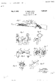
Other features and advantages will appear from the following description when taken in connection with the accompanying drawings, in which Figure 1 is a view in elevation showing the portion of the gun stock with our improved m-ounting attached thereto;
Figure 2 is an elevation on an enlarged scale;
Figure 3 is a front view looking towards the right in Figure 2;
Figure 4 is a bottom plan View showing the lever moved to position to permit the telescope to be removed;
Figure 5 is a sectional View on the line 55 of Figure 2;
Figure 6 is a sectional view of the telescope supporting bracket shown in Fig ure 3;
Figure 7 is a section on the line 7-7 of Figure 6, and
Figure 8 is a perspective View of the plate which is secured to the rifle breech.
Referring to the drawings, 1 indicates a plate of general rectangular form having screw holes by which it may be rigidly attached to the rifle breech. This plate, as shown in Figure 8, is provided with a dovetail at its upper edge having a rounded depression 2 therein.
The telescope supporting element 3 is provided with a dovetailed slot at its under portion, as shown in Figure 3, which fits the dovetail of the plate 1 when the two parts are slid together. The telescope supporting bracket 1 is adapted to be moved transversely of the supporting element 3 to adjust for windage in a manner which will be pointed outmore in detail hereinafter.
The other bracket 5 is detachably secured to the element 3 by a screw 6 which passes through said element 3 and into the bracket. This screw has another function that will also be pointed out later.
It is important that when the telescope mounting is slid upon the plate 1, it shall be firmly secured in place and it is highly desirable that such securing means be of such character that the telescope may be very quickly put in place and removed. These results are secured in the present invention by slitting the supporting element 3 in such a manner as to provide a tongue 7 Figures 4 and 5, which tongue then constitutes a portion of the element which is independently movable into engagement with the plate 1 whereby the two may be securely clamp-ed together. This clamping is brought about in the present invention by the lever 8 secured to a stub shaft or pin 9, which passes through the side of the supporting element 3 and through the tongue portion 7 thereof, which may be directly threaded or, as is shown in Figure 5, said tongue may be provided with a threaded sleeve 10, suitably secured to the tongue 7. When the lever 8 is moved from the position shown in Figure 4 to the position shown in Figures 1 and 3, the tongue or movable portion of the element 3 is moved into clamping relation with the plate 1.
In the present invention the friction between the tongue 7 and the plate 1 is not relied upon as the sole means to secure the parts firmly together, but in addition a positive locking action is brought about by providing inter-engaging means between the plate and the supporting element which positively prevents any longitudinal relative movement between them. In the present instance we have utilized the stub shaft 9 for this purpose and in order that it may thus serve it is flattened on one side, as shown in dotted lines in Figure 2, and when the lever 8 is in the position shown in Figure 4 the flattened portion of the shaft 9 forms a continuous surface With the bottom of the groove in the element 3, thereby permitting said element to slide along the plate 1, and the parts are shown thus positioned in Figure 2. In this figure it will be noted that the screw 6 abuts the plate 1, thus acting as a stop to determine the position that the supporting element 3 must occupy in relation to the plate 1 to bring the stub shaft 9 in position to engage the rounded notch or depression 2, in the plate 1. When the lever 8 is moved from the position shown in Figure 4: to the position shown in Figure 2, the rounded portion of the stub shaft or pin 9 engages in the notch 2 and positively prevents relative longitudinal movement of the parts. The pin 6 serves two functionsthat of supporting the bracket 5 and as a means for determining the proper position of the supporting element on the plate 1.
We have also provided an adjustment for windage and for this purpose the bracket 4 is provided with a dovetail 11 which fits into a dovetailed slot in the supporting element 3. A screw 12, provided with a, notched collar 13, rigidly secured thereto, seats in a recess 14:, of the supporting element 3, and is screw threaded into the side thereof as indicated in Figure 6. A downwardly projecting yoke 15 rigid wit-h or secured to the bracket 4, engages the groove in the collar 13 and by this construction turning of the screw 12 in either direction causes a corresponding movement of the bracket 4 in relation to the supporting element 3.
It is, of course, to be understood that variations may be resorted to within the scope of the invention without departing from the spirit thereof and some of the parts may be used without others.
hat we claim as new is:
1. A mounting for telescope sights for rifles and the like, having a grooved mounting plate adapted to be secured to the rifle breech, a support for the telescope longitudinally slit for a portion thereof to form a tongue fitting the groove in said plate, said plate having a depression at its upper side, a lever carried by the telescope support and having screw threaded engagement with said tongue and also having a portion adapted to enter the depression in said plate when the lever is moved to clamp the tongue and plate together.
2. A mounting for telescope sights for rifles and the like, including a grooved mounting plate, a telescope supporting element also grooved to slidingly fit the groove in said plate, a bracket for supporting one end of the telescope, a screw passing through said element and into said bracket, said screw also forming a stop engaging said plate for determining the proper position of said supporting element on the plate when the former is slid into engagement with the latter, and inter-engaging means between said plate and supporting element acting positively to prevent longitudinal relative movement thereof when the plate and support are in position as determined by said screw stop.
3. A mounting for telescope sights and the like including a grooved mounting plate, a telescope supporting element also grooved to slidingly fit the groove in said plate and having a tongue also fitting the groove in said plate, a bracket for supporting one end of the telescope, a screw passing through said element and into said bracket for securing the same to the support, said screw also forming a stop for determining the proper position of said supporting element on the plate when the former is slid into engagement with the latter, interengaging means between said plate and supporting element and a lever supported by said element and acting to render said inter-engaging means effective and to move said tongue into clamping relation with said plate.
4. A mounting for telescope sights for rifles and the like including a longitudinally grooved mounting plate, a support for a telescope longitudinally slit for a portion thereof to form a tongue fitting one of the grooves in said supporting plate, said plate having a depression at its upper side, a lever carried by the telescope support, means operated by said lever having screw-threaded engagement with said tongue and also having a portion adapted to enter the depression in said plate when the lever is moved to thereby clamp the tongue and plate together and positively prevent relative longitudinal movement between the telescope support and plate.
Signed at New York City, N. Y., this 28 day of October, 1927.
SEYMOUR GRIFFIN. ROBERT SPARE.
Priority Applications (1)
| Application Number | Priority Date | Filing Date | Title |
|---|---|---|---|
| US231055A US1856549A (en) | 1927-11-04 | 1927-11-04 | Gun sight support |
Applications Claiming Priority (1)
| Application Number | Priority Date | Filing Date | Title |
|---|---|---|---|
| US231055A US1856549A (en) | 1927-11-04 | 1927-11-04 | Gun sight support |
Publications (1)
| Publication Number | Publication Date |
|---|---|
| US1856549A true US1856549A (en) | 1932-05-03 |
Family
ID=22867584
Family Applications (1)
| Application Number | Title | Priority Date | Filing Date |
|---|---|---|---|
| US231055A Expired - Lifetime US1856549A (en) | 1927-11-04 | 1927-11-04 | Gun sight support |
Country Status (1)
| Country | Link |
|---|---|
| US (1) | US1856549A (en) |
Cited By (14)
| Publication number | Priority date | Publication date | Assignee | Title |
|---|---|---|---|---|
| US2427784A (en) * | 1945-10-24 | 1947-09-23 | Edward C Herkner | Mounting for telescope sights |
| US2436948A (en) * | 1945-07-14 | 1948-03-02 | Harvey A Williams | Mount for gun sights |
| US2545419A (en) * | 1946-06-15 | 1951-03-13 | Francis P Cleary | Telescope gun sight mounting |
| US2632251A (en) * | 1949-01-24 | 1953-03-24 | William R Weaver | Telescope mount |
| US2777202A (en) * | 1953-12-08 | 1957-01-15 | Adriano E Conte | Scope mount |
| US2810963A (en) * | 1954-05-12 | 1957-10-29 | American Optical Corp | Gun sight mounts |
| USD422045S (en) * | 1999-03-16 | 2000-03-28 | Fell Oscar M | Illuminating mount system for the Colt M16/AR15 and other assault type rifles |
| US6637144B2 (en) * | 2001-05-03 | 2003-10-28 | Itt Manufacturing Enterprises, Inc. | Sight clearing weapon mount |
| US6931779B1 (en) * | 2003-06-05 | 2005-08-23 | Daniel Galuppo, Jr. | Mounting device for attaching an auxiliary sight to a firearm |
| US20140373329A1 (en) * | 2013-06-20 | 2014-12-25 | Torrey Pines Logic, Inc. | Quick-detach accessory base mount for an accessory rail |
| US9303955B2 (en) * | 2014-03-21 | 2016-04-05 | Bo Sun Jeung | Locking mechanism for a small arm accessory |
| US10724569B2 (en) | 2018-04-21 | 2020-07-28 | Maxim Defense Industries, LLC | Universal interface system, fastener apparatus and accessory rail system |
| US10955221B2 (en) * | 2019-06-07 | 2021-03-23 | Premier Shooting Solutions LLC | Optic mount assembly |
| USD1004033S1 (en) | 2020-01-20 | 2023-11-07 | Sagi Faifer | Handguard for a gun |
-
1927
- 1927-11-04 US US231055A patent/US1856549A/en not_active Expired - Lifetime
Cited By (20)
| Publication number | Priority date | Publication date | Assignee | Title |
|---|---|---|---|---|
| US2436948A (en) * | 1945-07-14 | 1948-03-02 | Harvey A Williams | Mount for gun sights |
| US2427784A (en) * | 1945-10-24 | 1947-09-23 | Edward C Herkner | Mounting for telescope sights |
| US2545419A (en) * | 1946-06-15 | 1951-03-13 | Francis P Cleary | Telescope gun sight mounting |
| US2632251A (en) * | 1949-01-24 | 1953-03-24 | William R Weaver | Telescope mount |
| US2777202A (en) * | 1953-12-08 | 1957-01-15 | Adriano E Conte | Scope mount |
| US2810963A (en) * | 1954-05-12 | 1957-10-29 | American Optical Corp | Gun sight mounts |
| USD422045S (en) * | 1999-03-16 | 2000-03-28 | Fell Oscar M | Illuminating mount system for the Colt M16/AR15 and other assault type rifles |
| US6637144B2 (en) * | 2001-05-03 | 2003-10-28 | Itt Manufacturing Enterprises, Inc. | Sight clearing weapon mount |
| US6931778B1 (en) | 2001-05-03 | 2005-08-23 | Itt Manufacturing Enterprises, Inc. | Clamp for weapon mount |
| US6931779B1 (en) * | 2003-06-05 | 2005-08-23 | Daniel Galuppo, Jr. | Mounting device for attaching an auxiliary sight to a firearm |
| US20140373329A1 (en) * | 2013-06-20 | 2014-12-25 | Torrey Pines Logic, Inc. | Quick-detach accessory base mount for an accessory rail |
| US9038305B2 (en) * | 2013-06-20 | 2015-05-26 | Torrey Pines Logic, Inc. | Quick-detach accessory base mount for an accessory rail |
| US20150253113A1 (en) * | 2013-06-20 | 2015-09-10 | Torrey Pines Logic, Inc. | Quick-detach accessory base mount for an accessory rail |
| US20150260482A1 (en) * | 2013-06-20 | 2015-09-17 | Torrey Pines Logic LLC | Quick-detach accessory base mount for an accessory rail |
| US9328998B2 (en) * | 2013-06-20 | 2016-05-03 | Torrey Pines Logic Inc. | Quick-detach accessory base mount for an accessory rail |
| US9644922B2 (en) * | 2013-06-20 | 2017-05-09 | Torrey Pines Logic, Inc. | Quick-detach accessory base mount for an accessory rail |
| US9303955B2 (en) * | 2014-03-21 | 2016-04-05 | Bo Sun Jeung | Locking mechanism for a small arm accessory |
| US10724569B2 (en) | 2018-04-21 | 2020-07-28 | Maxim Defense Industries, LLC | Universal interface system, fastener apparatus and accessory rail system |
| US10955221B2 (en) * | 2019-06-07 | 2021-03-23 | Premier Shooting Solutions LLC | Optic mount assembly |
| USD1004033S1 (en) | 2020-01-20 | 2023-11-07 | Sagi Faifer | Handguard for a gun |
Similar Documents
| Publication | Publication Date | Title |
|---|---|---|
| US1856549A (en) | Gun sight support | |
| US2545419A (en) | Telescope gun sight mounting | |
| US3750318A (en) | Riflescope mount | |
| US2571935A (en) | Telescopic sight mount | |
| US2641057A (en) | Telescope mounting | |
| US2857675A (en) | Quick detachable scope mount with windage | |
| US2491431A (en) | Telescope mounting | |
| US2202000A (en) | Telescope sight mounting | |
| US1428655A (en) | Telescope-sight mounting | |
| US2073210A (en) | Gun-sight mount | |
| US2101037A (en) | Telescopic sight for guns | |
| US3199202A (en) | Gun sight mounting | |
| US2763930A (en) | Detachable top mount | |
| US2018960A (en) | Telescope sight mounting | |
| US1842724A (en) | Clamping device for extension leveling rods | |
| US2475383A (en) | Quick detachable telescope sight mount | |
| US2479594A (en) | Barrel support means for firearms | |
| US1438694A (en) | Rear sight for firearms | |
| US1756603A (en) | Gun-sight mounting | |
| US3401460A (en) | Arrangement for adjusting the line of sight of a sighting telescope | |
| US2563849A (en) | Telescope mount for rifles | |
| US2345249A (en) | Telescopic sight mount for rifles | |
| US2377704A (en) | Gun sight | |
| US2108150A (en) | Sight for firearms | |
| US2871566A (en) | Sight system for firearms |