US1854912A - Lamp starting device - Google Patents
Lamp starting device Download PDFInfo
- Publication number
- US1854912A US1854912A US421680A US42168030A US1854912A US 1854912 A US1854912 A US 1854912A US 421680 A US421680 A US 421680A US 42168030 A US42168030 A US 42168030A US 1854912 A US1854912 A US 1854912A
- Authority
- US
- United States
- Prior art keywords
- envelope
- light
- mercury
- current
- energizing
- Prior art date
- Legal status (The legal status is an assumption and is not a legal conclusion. Google has not performed a legal analysis and makes no representation as to the accuracy of the status listed.)
- Expired - Lifetime
Links
- QSHDDOUJBYECFT-UHFFFAOYSA-N mercury Chemical compound [Hg] QSHDDOUJBYECFT-UHFFFAOYSA-N 0.000 description 25
- 239000007789 gas Substances 0.000 description 21
- 229910052753 mercury Inorganic materials 0.000 description 20
- 229910052754 neon Inorganic materials 0.000 description 9
- GKAOGPIIYCISHV-UHFFFAOYSA-N neon atom Chemical compound [Ne] GKAOGPIIYCISHV-UHFFFAOYSA-N 0.000 description 9
- 230000006698 induction Effects 0.000 description 5
- 239000000463 material Substances 0.000 description 5
- 230000003534 oscillatory effect Effects 0.000 description 4
- XKRFYHLGVUSROY-UHFFFAOYSA-N Argon Chemical compound [Ar] XKRFYHLGVUSROY-UHFFFAOYSA-N 0.000 description 2
- 239000004020 conductor Substances 0.000 description 2
- 239000011521 glass Substances 0.000 description 2
- 238000009877 rendering Methods 0.000 description 2
- 239000012780 transparent material Substances 0.000 description 2
- 241000518994 Conta Species 0.000 description 1
- 241000124032 Paracheirodon axelrodi Species 0.000 description 1
- 229910052786 argon Inorganic materials 0.000 description 1
- 238000011010 flushing procedure Methods 0.000 description 1
- -1 for example Substances 0.000 description 1
- 229910052734 helium Inorganic materials 0.000 description 1
- 239000001307 helium Substances 0.000 description 1
- SWQJXJOGLNCZEY-UHFFFAOYSA-N helium atom Chemical compound [He] SWQJXJOGLNCZEY-UHFFFAOYSA-N 0.000 description 1
- 230000001939 inductive effect Effects 0.000 description 1
- 229910052743 krypton Inorganic materials 0.000 description 1
- DNNSSWSSYDEUBZ-UHFFFAOYSA-N krypton atom Chemical compound [Kr] DNNSSWSSYDEUBZ-UHFFFAOYSA-N 0.000 description 1
- WABPQHHGFIMREM-UHFFFAOYSA-N lead(0) Chemical compound [Pb] WABPQHHGFIMREM-UHFFFAOYSA-N 0.000 description 1
- 238000004519 manufacturing process Methods 0.000 description 1
- 239000010453 quartz Substances 0.000 description 1
- VYPSYNLAJGMNEJ-UHFFFAOYSA-N silicon dioxide Inorganic materials O=[Si]=O VYPSYNLAJGMNEJ-UHFFFAOYSA-N 0.000 description 1
- 239000000126 substance Substances 0.000 description 1
- 230000008016 vaporization Effects 0.000 description 1
- 229910052724 xenon Inorganic materials 0.000 description 1
- FHNFHKCVQCLJFQ-UHFFFAOYSA-N xenon atom Chemical compound [Xe] FHNFHKCVQCLJFQ-UHFFFAOYSA-N 0.000 description 1
Images
Classifications
-
- H—ELECTRICITY
- H01—ELECTRIC ELEMENTS
- H01J—ELECTRIC DISCHARGE TUBES OR DISCHARGE LAMPS
- H01J65/00—Lamps without any electrode inside the vessel; Lamps with at least one main electrode outside the vessel
- H01J65/04—Lamps in which a gas filling is excited to luminesce by an external electromagnetic field or by external corpuscular radiation, e.g. for indicating plasma display panels
- H01J65/042—Lamps in which a gas filling is excited to luminesce by an external electromagnetic field or by external corpuscular radiation, e.g. for indicating plasma display panels by an external electromagnetic field
- H01J65/048—Lamps in which a gas filling is excited to luminesce by an external electromagnetic field or by external corpuscular radiation, e.g. for indicating plasma display panels by an external electromagnetic field the field being produced by using an excitation coil
Definitions
- I proyide an envelope of glass or other suitable transparent material, containing a fillin of rare gas such as neon, and having attac e d thereto an auxiliary chamber or reservoir containing a quantity of mercury.
- an induction coil which is placed around the envelope and connected to oscillator means so as to produce a magnetic field.
- the mercury electrode is also provided with oscillatory energizing means which may be controlled by a tunin. device. This may be done, for example, y providing a suitable connection through a tunin device, from the induction coil to a lead-in wire sealed through the wall of the envelope and contating'with the mercury in the auxiliary reservoir.
- the light produced will be characteristic of the gas used.
- the filling in the envelope comprises neon
- the, light produced will be orange red.
- the color of the emitted light may be modified, however, merely by adjusting the tuningof the auxiliary circuit of the mercury electrode.
- the current flow through the mercury electrode may be increasedto such an extent that mercury vapor is produced, which vapor penetrates the entireinside of .the envelope and adds to the characteristic red color of the neon, the blue color of mercury, thereby producing a-whitish light.
- the color of the emitted light may be made of any value desired, between the extreme limits of substantially pure mercury color and the characteristic red neon color.
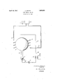
- reference numeral 1 indicates an envelope of glass, quartz, or other suitable transparent material, containing a filling of rare gas, e. g., neon, and having an auxiliary electrode chamber or appendix 2 containing a quantity of mercury or other 'suitable light modifying material 3.
- an induction coil 4 Placed around the outside of the main portion of the envelope, which may beeither spherical, cylindrlcal, or of any other desired shape, is an induction coil 4. This acts as the primary of an exciting transformer, the secondary of which is the gas within the envelope. Energizing current is supplied to the two terminals 6 and 7 of the coil from a source 8.
- This source may be, for example, a vacuum tube oscillator of high frequency which is adapted, in the well-known manner, to have its output current modulated in accordance with a feeble "signal current input which may be received from a distant point over input line 9 and suitably amplified.
- a vacuum tube oscillator of high frequency which is adapted, in the well-known manner, to have its output current modulated in accordance with a feeble "signal current input which may be received from a distant point over input line 9 and suitably amplified.
- anint'ense magnetic fielfQs created by the coil 4, thereby inducing a current in the as within the envelope 1, which acts as a s ort circuited secondary therefor.
- the .gas is ionized and caused to produce light.
- the gas may be caused to emit a ver concentrated light of high brilliancy. This light will be emitted at substantially uniform intensity over the entire projected area of the lamp bulb, thereby giving a relatively wide source 'of light, the brilliancy offwhich may be varied.
- the unnatural color which would result from the use of a single gas, such as neon, within the bulb, is overcome by an auxiliary energizing circuit 10 which serves to conduct current to the mercury electrode?
- This auxiliary circuit comprises a lead wire 11 connected to one side of the line leading from the source of current 8, and a conductor 12 connected to a lead-in wire 13 sealed through the wall of the envelope 1 and conta'cting with the mercury 3.
- an inductance coil 14 Between the conductors 11 and 12 are connected an inductance coil 14 and a variable condenser 15. Magnetically coupled to the inductance coil 14 is velope 1 and mingling with the rare gas therein.
- the mercury vapor is also ionized and caused to emit light by the passage of the induced current therethrough, the result being that the blue light emitted by the mercury combines with the red light of the neon gas and thereby produces a more nearly white color.
- the condenser 15 is adjusted so that but a slight amount of current is passed through the mercury electrode circuit, only a slight amount of vapor will be generated, consequently the li ht emitted from the envelope will be substantially neon red in color.
- the condenser 15 by adjusting the condenser 15 so that the auxiliary circuit 10 is more nearly in resonance with the energizing source of the primary coil 16, more mercury vapor is evolved light emitted from the envelope may be substantially white. By still more nearly approaching resonance the amount of mercury vapor evolved may be great enough to cause the emitted light to have the characteristic mercury color.
- the auxiliary circuit 10 may be adjusted approximately to resonance with the frequency of the oscillatory source 8, whereby a portion of the current passing to the coil 4 may be diverted to the circuit of the mercury 3, thereby evolving mercury vapor sfifiiciently to modify the color of'the light emitted from the envelope 1.
- the auxiliary circuit 10 By modulating the output potential of the source 8 by varying the potential of the control circuit 9, it is possible to vary the brilliancy of the light emitted from the envelope 1 without varying the color thereof appreciably.
- the auxiliary circuit 10 is. once adjusted so that the emitted light is substantially white, or of any desired color, the color of the light will remain unimpaired while the brilliancy thereof is varied.
- the modulating current of the control circuit 9 may be received from a distant station either by radio or direct connection. This current, if relatively feeble, may of course be suitably amplified in any known manner to any level desirable for controlling the oscillator 8.
- any of the rare gases for example, helium, argon, xenon, or krypton may be used as well.
- the resulting light will, however be modified accordingly.
- an envelope containing a filling of rare gas, an auxiliary chamber attached to said envelope, a quantity of mercury in said chamber, means for energizing the gas in said envelope by magnetic induction, and separate means for vaporizing a quantity of said mercury.
- the energizing means comprises a coil of wire surrounding said envelope.
- an envelope containing a filling o rare gas an envelope containing a filling o rare gas, an auxiliary chamber attached to said envelope, 9. quantity of light modifying material in said envelope, means for supplymg alternating current of high frequency for energizing said rare gas, a high frequency circuit for rendering effective said light modifying material, and means for tuning said circuit in order to control the degree of effectiveness of said light modifying means.
- an envelope containing a filling of rare gas, a quantity of light modifying material for said envelope, a vacuum tube oscillator for energizing-said rare gas,ineans energized by said oscillator for rendering effective said light modifying material, tuning means for controlling the flow of current to said means first mentioned, and
- control means for varying the effectiveness of said oscillator.
- an envelope containing a rare gas containing a rare gas
- a reservoir attached to said envelope, a quantity of mercury in said reservoir, a lead-in wire for said mercury, a coil of wire surrounding said envelope a source of high frequency current for energizing said coil, and a control circuit connection from said coil to said lead-in wire including an inductance and a tuning capacity.
- a gaseous discharge lamp having a main energizing circuit, an auxiliary color modifying circuit, an oscillatory current supply source common to both of said circuits, and means for modulating the frequency of said oscillatory current.
Description
April 19, 1932.
cv S PAETH LAMP STARTING DEVICE Filed Jan. 18, 1930 can awes- SPA a-r'H,
INVENTOR ATTORNEY Patented Apr. 19, 1932 UNITED STATES- PATENT OFFICE CHARLES SPAETH, 0F FLUSHING, NEW YORK, ABSIGNO3 TO NE-ABGA CORPORATION,
' OF NEW YORK, N. 11, .A. CORPORATION DIE-NEW YORK LAMP srea'rma msvrcn Application filed January 18 1930. 8eria1 No. 421,680.
In accordance with my invention I proyide an envelope of glass or other suitable transparent material, containing a fillin of rare gas such as neon, and having attac e d thereto an auxiliary chamber or reservoir containing a quantity of mercury. For energizing the gas within the envelope- I provide an induction coil which is placed around the envelope and connected to oscillator means so as to produce a magnetic field. The mercury electrode is also provided with oscillatory energizing means which may be controlled by a tunin. device. This may be done, for example, y providing a suitable connection through a tunin device, from the induction coil to a lead-in wire sealed through the wall of the envelope and contating'with the mercury in the auxiliary reservoir. By energizing the induction coil a current is made to circulate through the gas within the envelopeand cause ionization, which results in the production of light.
Disregarding the eflect of mercury the light produced will be characteristic of the gas used. For example, when the filling in the envelope comprises neon, the, light produced will be orange red. The color of the emitted light may be modified, however, merely by adjusting the tuningof the auxiliary circuit of the mercury electrode. By adjusting the auxiliary circuit more nearly to resonance with the requency of the energizing source, the current flow through the mercury electrode may be increasedto such an extent that mercury vapor is produced, which vapor penetrates the entireinside of .the envelope and adds to the characteristic red color of the neon, the blue color of mercury, thereby producing a-whitish light.
By adjusting the tuning of the auxiliary circuit the color of the emitted light may be made of any value desired, between the extreme limits of substantially pure mercury color and the characteristic red neon color.
The above mentioned and other objects and advantages-and the manner of attaining them will be made clear in the following description and accompanying drawing.
In the drawing, reference numeral 1 indicates an envelope of glass, quartz, or other suitable transparent material, containing a filling of rare gas, e. g., neon, and having an auxiliary electrode chamber or appendix 2 containing a quantity of mercury or other 'suitable light modifying material 3. Placed around the outside of the main portion of the envelope, which may beeither spherical, cylindrlcal, or of any other desired shape, is an induction coil 4. This acts as the primary of an exciting transformer, the secondary of which is the gas within the envelope. Energizing current is supplied to the two terminals 6 and 7 of the coil from a source 8. This source may be, for example, a vacuum tube oscillator of high frequency which is adapted, in the well-known manner, to have its output current modulated in accordance with a feeble "signal current input which may be received from a distant point over input line 9 and suitably amplified. For instance, when the oscillator 8 is put into operation, anint'ense magnetic fielfQs created by the coil 4, thereby inducing a current in the as within the envelope 1, which acts as a s ort circuited secondary therefor. As a result of this, the .gas is ionized and caused to produce light. By suitably increasing the strength of the energizing current, which should be of high freq'tiency, the gas may be caused to emit a ver concentrated light of high brilliancy. This light will be emitted at substantially uniform intensity over the entire projected area of the lamp bulb, thereby giving a relatively wide source 'of light, the brilliancy offwhich may be varied. The unnatural color which would result from the use of a single gas, such as neon, within the bulb, is overcome by an auxiliary energizing circuit 10 which serves to conduct current to the mercury electrode? This auxiliary circuit comprises a lead wire 11 connected to one side of the line leading from the source of current 8, and a conductor 12 connected to a lead-in wire 13 sealed through the wall of the envelope 1 and conta'cting with the mercury 3. Between the conductors 11 and 12 are connected an inductance coil 14 and a variable condenser 15. Magnetically coupled to the inductance coil 14 is velope 1 and mingling with the rare gas therein. The mercury vapor is also ionized and caused to emit light by the passage of the induced current therethrough, the result being that the blue light emitted by the mercury combines with the red light of the neon gas and thereby produces a more nearly white color. If the condenser 15 is adjusted so that but a slight amount of current is passed through the mercury electrode circuit, only a slight amount of vapor will be generated, consequently the li ht emitted from the envelope will be substantially neon red in color. However, by adjusting the condenser 15 so that the auxiliary circuit 10 is more nearly in resonance with the energizing source of the primary coil 16, more mercury vapor is evolved light emitted from the envelope may be substantially white. By still more nearly approaching resonance the amount of mercury vapor evolved may be great enough to cause the emitted light to have the characteristic mercury color.
Instead of utilizing a primary energizing inductance 16, the auxiliary circuit 10 may be adjusted approximately to resonance with the frequency of the oscillatory source 8, whereby a portion of the current passing to the coil 4 may be diverted to the circuit of the mercury 3, thereby evolving mercury vapor sfifiiciently to modify the color of'the light emitted from the envelope 1.
By modulating the output potential of the source 8 by varying the potential of the control circuit 9, it is possible to vary the brilliancy of the light emitted from the envelope 1 without varying the color thereof appreciably. When the auxiliary circuit 10 is. once adjusted so that the emitted light is substantially white, or of any desired color, the color of the light will remain unimpaired while the brilliancy thereof is varied.
The modulating current of the control circuit 9 may be received from a distant station either by radio or direct connection. This current, if relatively feeble, may of course be suitably amplified in any known manner to any level desirable for controlling the oscillator 8.
While I have specified neon as the gas preferably used in the envelope, any of the rare gases, for example, helium, argon, xenon, or krypton may be used as well. The resulting light will, however be modified accordingly.
What is claimed is:
1. In a light source, an envelope containing a filling of rare gas, an auxiliary chamber attached to said envelope, a quantity of mercury in said chamber, means for energizing the gas in said envelope by magnetic induction, and separate means for vaporizing a quantity of said mercury.
2. A device in accordance with claim 1, wherein the energizing means comprises a coil of wire surrounding said envelope.
3. In a television li ht source, an envelope containing a filling o rare gas, an auxiliary chamber attached to said envelope, 9. quantity of light modifying material in said envelope, means for supplymg alternating current of high frequency for energizing said rare gas, a high frequency circuit for rendering effective said light modifying material, and means for tuning said circuit in order to control the degree of effectiveness of said light modifying means.
4. A device accordin to claim 3 wherein the rare gas is neon an the light modifying substance is mercury.
5. In a television system, an envelope containing a filling of rare gas, a quantity of light modifying material for said envelope, a vacuum tube oscillator for energizing-said rare gas,ineans energized by said oscillator for rendering effective said light modifying material, tuning means for controlling the flow of current to said means first mentioned, and
control means for varying the effectiveness of said oscillator.
6. In a light source, an envelope containing a rare gas, a reservoir attached to said envelope, a quantity of mercury in said reservoir, a lead-in wire for said mercury, a coil of wire surrounding said envelope a source of high frequency current for energizing said coil, and a control circuit connection from said coil to said lead-in wire including an inductance and a tuning capacity.
7. A device in accordance with claim 6, wherein a source of oscillating current is coupled to said control circuit.
8. A gaseous discharge lamp having a main energizing circuit, an auxiliary color modifying circuit, an oscillatory current supply source common to both of said circuits, and means for modulating the frequency of said oscillatory current.
In testimony whereof, I havesigned my name to this specification, this 16th day of January, 1930.
' CHARLES SPAETH.
Priority Applications (1)
| Application Number | Priority Date | Filing Date | Title |
|---|---|---|---|
| US421680A US1854912A (en) | 1930-01-18 | 1930-01-18 | Lamp starting device |
Applications Claiming Priority (1)
| Application Number | Priority Date | Filing Date | Title |
|---|---|---|---|
| US421680A US1854912A (en) | 1930-01-18 | 1930-01-18 | Lamp starting device |
Publications (1)
| Publication Number | Publication Date |
|---|---|
| US1854912A true US1854912A (en) | 1932-04-19 |
Family
ID=23671584
Family Applications (1)
| Application Number | Title | Priority Date | Filing Date |
|---|---|---|---|
| US421680A Expired - Lifetime US1854912A (en) | 1930-01-18 | 1930-01-18 | Lamp starting device |
Country Status (1)
| Country | Link |
|---|---|
| US (1) | US1854912A (en) |
Cited By (8)
| Publication number | Priority date | Publication date | Assignee | Title |
|---|---|---|---|---|
| US2564157A (en) * | 1947-06-12 | 1951-08-14 | Eknayan Hrant | Electric heating system and method of heating |
| DE1179298B (en) * | 1960-09-16 | 1964-10-08 | Varian Associates | High frequency powered spectral lamp with accessories |
| DE1295082B (en) * | 1962-01-10 | 1969-05-14 | Csf | Absorption cell for optical measurements on resonance lines |
| US4742278A (en) * | 1987-06-03 | 1988-05-03 | Iannini Robert E | Single connection gas discharge display and driver |
| DE3938827A1 (en) * | 1988-12-22 | 1990-06-28 | Matsushita Electric Works Ltd | ELECTRODELESS DISCHARGE LAMP |
| US5386181A (en) * | 1992-01-24 | 1995-01-31 | Neon Dynamics Corporation | Swept frequency switching excitation supply for gas discharge tubes |
| US6137237A (en) * | 1998-01-13 | 2000-10-24 | Fusion Lighting, Inc. | High frequency inductive lamp and power oscillator |
| US6313587B1 (en) | 1998-01-13 | 2001-11-06 | Fusion Lighting, Inc. | High frequency inductive lamp and power oscillator |
-
1930
- 1930-01-18 US US421680A patent/US1854912A/en not_active Expired - Lifetime
Cited By (13)
| Publication number | Priority date | Publication date | Assignee | Title |
|---|---|---|---|---|
| US2564157A (en) * | 1947-06-12 | 1951-08-14 | Eknayan Hrant | Electric heating system and method of heating |
| DE1179298B (en) * | 1960-09-16 | 1964-10-08 | Varian Associates | High frequency powered spectral lamp with accessories |
| DE1295082B (en) * | 1962-01-10 | 1969-05-14 | Csf | Absorption cell for optical measurements on resonance lines |
| US4742278A (en) * | 1987-06-03 | 1988-05-03 | Iannini Robert E | Single connection gas discharge display and driver |
| DE3938827A1 (en) * | 1988-12-22 | 1990-06-28 | Matsushita Electric Works Ltd | ELECTRODELESS DISCHARGE LAMP |
| US5386181A (en) * | 1992-01-24 | 1995-01-31 | Neon Dynamics Corporation | Swept frequency switching excitation supply for gas discharge tubes |
| US6137237A (en) * | 1998-01-13 | 2000-10-24 | Fusion Lighting, Inc. | High frequency inductive lamp and power oscillator |
| US6225756B1 (en) | 1998-01-13 | 2001-05-01 | Fusion Lighting, Inc. | Power oscillator |
| US6252346B1 (en) | 1998-01-13 | 2001-06-26 | Fusion Lighting, Inc. | Metal matrix composite integrated lamp head |
| US6313587B1 (en) | 1998-01-13 | 2001-11-06 | Fusion Lighting, Inc. | High frequency inductive lamp and power oscillator |
| US6326739B1 (en) | 1998-01-13 | 2001-12-04 | Fusion Lighting, Inc. | Wedding ring shaped excitation coil |
| US20020167282A1 (en) * | 1998-01-13 | 2002-11-14 | Kirkpatrick Douglas A. | High frequency inductive lamp and power oscillator |
| US6949887B2 (en) | 1998-01-13 | 2005-09-27 | Intel Corporation | High frequency inductive lamp and power oscillator |
Similar Documents
| Publication | Publication Date | Title |
|---|---|---|
| US2525624A (en) | Glow lamp combination | |
| US2453118A (en) | Concentrated arc discharge device | |
| US1854912A (en) | Lamp starting device | |
| US2624858A (en) | Gaseous discharge lamp | |
| US2118452A (en) | Electric lamp | |
| US843534A (en) | Method of producing electric light. | |
| US2038049A (en) | Low voltage gas arc lamp | |
| US2117544A (en) | Lighting by sustained luminescence | |
| US2349012A (en) | Means for producing high frequency oscillations in illuminating electronic dischargelamp devices | |
| GB1026061A (en) | Improvements in or relating to plasma tube arrangements | |
| US1908649A (en) | Electrical discharge device | |
| US2223399A (en) | Supply of electric discharge tubes excited inductively | |
| US2190009A (en) | Luminescent tube and system | |
| US1819105A (en) | High frequency luminous tube | |
| US2783407A (en) | Source of light | |
| US1827705A (en) | Method of modifying color in vacuum tube lights | |
| US1912097A (en) | Electric glow discharge tube | |
| USRE21150E (en) | Source of light and method of oper | |
| US1876083A (en) | Electric discharge device | |
| JPS6297298A (en) | Non-electrode discharge lamp apparatus | |
| US2176151A (en) | Electric lamp | |
| US1785070A (en) | Inductive light source | |
| US1807927A (en) | Mercury vapor lamp | |
| US1954025A (en) | Electrooptical system | |
| US1872567A (en) | Discharge tube |