US18522A - Improvement in sewing-machines - Google Patents
Improvement in sewing-machines Download PDFInfo
- Publication number
- US18522A US18522A US18522DA US18522A US 18522 A US18522 A US 18522A US 18522D A US18522D A US 18522DA US 18522 A US18522 A US 18522A
- Authority
- US
- United States
- Prior art keywords
- needle
- cloth
- thread
- lever
- hook
- Prior art date
- Legal status (The legal status is an assumption and is not a legal conclusion. Google has not performed a legal analysis and makes no representation as to the accuracy of the status listed.)
- Expired - Lifetime
Links
- 239000004744 fabric Substances 0.000 description 44
- 238000009958 sewing Methods 0.000 description 10
- 230000015572 biosynthetic process Effects 0.000 description 6
- 238000005755 formation reaction Methods 0.000 description 6
Images
Classifications
-
- D—TEXTILES; PAPER
- D05—SEWING; EMBROIDERING; TUFTING
- D05B—SEWING
- D05B1/00—General types of sewing apparatus or machines without mechanism for lateral movement of the needle or the work or both
- D05B1/02—General types of sewing apparatus or machines without mechanism for lateral movement of the needle or the work or both for making single-thread seams
Definitions
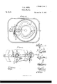
- Figurel is a perspective view.
- Fig. 2 is a side sectional'elevation.
- Fig. 3 is a top view of the machinery immediately under the top of the table.
- Fig. 4 is a bottom view of said machine.
- Fig. 5 is an end sectional view of the arm in which the needle-bar plays. an end view of the feeding apparatus;
- Fig. 7, an enlarged view of the needle.
- Fig'. 8 illustrates the several stages of the formation of the stitch, and the three kinds of stitch which my machine will make.
- B is an arm, fastened onto said table, containing the needlebar, which gives motion to the same; also the cloth-presser.
- G is the ily-wheel, upon the upper side of which is cut the cam to give motion to the needle, and also the cam to give motion to the thread-guide.
- D is the lever, working the needle-bar.
- E is the needle-bar.
- F is the feed-lever.
- G is the feed-wheel.
- H is the crank. I is the handle to the crank.
- K is a friction-spring for the feed-wheel.
- a is the needle. bis the cloth-presser.
- c is a lever to raise the cloth-presser.
- d is a spring to hold the cloth-presserdown on the cloth.
- ⁇ are two plates nicely tted into the groove f l in the feed-wheel.
- g is a short lever, one end of which is attached to the feed-lever, and the other end has a projection, t', which extends in between the two plates c e in such manner that when the feed-lever F is moved either way the projection 'i will press the .plates e e hard against the sides of the groove f, so that they will not' slip in it, but will cause the feedwheel to turn round when the lever g is thus moved.
- 7L and j are two springs to keep the projection fi stationary until it binds the plates e e.
- k is a stud on which the feed-wheel turns.
- Z and m are two screws in the sides of the feeding.
- c is lever, and so arranged that the cam o will p, and is used in connection with the cam o and the two screws m and p in sewing the running-stitch.
- q is a rod, one end of which is fastened into the cylinder s, which is fitted movably onto the hub of the fly-wheel C, and the other end is formed into a hook, r, and extends up to the upper side of the ily-wheel, at the edge, through a place cut out suitably for it to play in.
- This hook is to take the thread out of the hook of the needle and carry it sufficiently far around the edge" of the iiywheel that the end may pass entirely through the cloth each stitch that is sewed.
- On the opposite side of the cylinder s is a rod t, upon which is fitted a movable block, w, with a set-screw in it.
- the nut u is adjustable, and when it is near the other end of the rod t it gives a greater, and when near the cylinder s gives a less, spring-force to the hook o".
- a XVe will suppose the machine is turned by -moving the crank H to such position as will bring the needle to its highest position above the cloth z, as seen in example l, Fig. 8.
- rI ⁇ he thread N is there taken from the spool N', carried around the screw-handle d', and then placed Ain one of the hooks of the needle a, which said needle is formed with two hooks for the purpose of carrying the thread bothA ways through the cloth, as shown in a front and side view, on alarge scale, in Fig. 7.
- the thread-guide w is then moved toward the needle, (though a little to one side of it,) causing the proj ection x to press the thread against the spring y, which is passed between them by the hook r, which holds it lirm, while the thread-guide moves still farther and wraps the thread partly around the needle, causing it to pass into the hooks of the needle when they come up even with the said thread, as shown in Example 4.
- Example 9 the cloth is fed back only onethird the distance of the forward feeding, and in sewing the running-stitch, seen in Example 10, the cloth is fed forward the length of a stitch in the formation of each stitch without backfeeding by means of the cams 0 and n pressing against the screws m and p, causing the feedlever and the lever g to move in the direction of the spring h every half-round of the machine, and moving the feed-wheel, as before described.
- the needle carries the thread down and rises up a little, forming a loop, and the hook r passing into said loop, as shown at Example 6, which is the same as Example 2, except that another stitch hasbeen sewed.
- the needle rises up the hook r takes the thread through the cloth and around the flywheel, bringing the needle, the cloth, and the thread in the positions shown in example 7.
Description
2 Sheets-Sheet 1. S. H. ROPtR.
Sewing Machine.
,UNITED STATES` PATE-NT Ottieni..A
s. npnornn, or RoXBURv, MASSACHUSETTS.
IMPROVEMENT IN ISEWING-MACHINES.
Specification forming part of Letters Patent No. 18,522, dated October 277, 1857.
To all vwhom, t may concern,.-
Be it known that I, S. H. ROPER, of Roxbury, county of Norfolk, and State of Mass/achusetts, have invented a new and useful Improvement on the Sewing-Machine; and I do hereby declare that th e following is a full, clear, and exact description of the same, reference being had to the annexed drawings, making a part of this specification.
Each letter of reference will designate the same part in the several drawings.
In the specification of my machine, Figurel is a perspective view. Fig. 2 is a side sectional'elevation. Fig. 3 is a top view of the machinery immediately under the top of the table. Fig. 4 is a bottom view of said machine. Fig. 5 is an end sectional view of the arm in which the needle-bar plays. an end view of the feeding apparatus; Fig. 7, an enlarged view of the needle.` Fig'. 8 illustrates the several stages of the formation of the stitch, and the three kinds of stitch which my machine will make.
In specifying the parts of said machine, A
represents a table or stand, to which most of.
the machinery is attached. B is an arm, fastened onto said table, containing the needlebar, which gives motion to the same; also the cloth-presser. G is the ily-wheel, upon the upper side of which is cut the cam to give motion to the needle, and also the cam to give motion to the thread-guide. D is the lever, working the needle-bar. E is the needle-bar. F is the feed-lever. G is the feed-wheel. H is the crank. I is the handle to the crank. K is a friction-spring for the feed-wheel. a is the needle. bis the cloth-presser. c is a lever to raise the cloth-presser. d is a spring to hold the cloth-presserdown on the cloth. e e
` are two plates nicely tted into the groove f l in the feed-wheel.
g is a short lever, one end of which is attached to the feed-lever, and the other end has a projection, t', which extends in between the two plates c e in such manner that when the feed-lever F is moved either way the projection 'i will press the .plates e e hard against the sides of the groove f, so that they will not' slip in it, but will cause the feedwheel to turn round when the lever g is thus moved. 7L and j are two springs to keep the projection fi stationary until it binds the plates e e. k is a stud on which the feed-wheel turns. Z and m are two screws in the sides of the feeding. c is lever, and so arranged that the cam o will p, and is used in connection with the cam o and the two screws m and p in sewing the running-stitch.
q is a rod, one end of which is fastened into the cylinder s, which is fitted movably onto the hub of the fly-wheel C, and the other end is formed into a hook, r, and extends up to the upper side of the ily-wheel, at the edge, through a place cut out suitably for it to play in. This hook is to take the thread out of the hook of the needle and carry it sufficiently far around the edge" of the iiywheel that the end may pass entirely through the cloth each stitch that is sewed. On the opposite side of the cylinder s is a rod t, upon which is fitted a movable block, w, with a set-screw in it. spring, n, the other end of which is fastened to the under surface of the fly-wheel, and all arranged in such manner that the springe will keep the rod q and the hook r in the position shown in Figs. 3 and 4 relatively to the flywheel, yet so that said hook will yield a little, and even pass back to the position 1" before the thread will break in case the thread should be too tight in the cloth to slip through it without breaking until the needle withdraws. The nut u is adjustable, and when it is near the other end of the rod t it gives a greater, and when near the cylinder s gives a less, spring-force to the hook o".
to is a small slide or thread-guide fitted movably into the under side of the plate J,.with a roll, fw', projecting downward from one end into the groove w, in such manner that the slide w is operated thereby. At theend of said slide, near the needle, there is a small projection, x, so formed that when the slide w is moved toward the needle the projection x will press against the side of the springt, so as to hold the thread between them, and to keep it tense, and thereby more effectually guide it into the hook of the needle. z is the cloth.
Having described the several parts of my machine, I will proceed to eXplain'its operation.
To this block is attached a XVe will suppose the machine is turned by -moving the crank H to such position as will bring the needle to its highest position above the cloth z, as seen in example l, Fig. 8. rI`he thread N is there taken from the spool N', carried around the screw-handle d', and then placed Ain one of the hooks of the needle a, which said needle is formed with two hooks for the purpose of carrying the thread bothA ways through the cloth, as shown in a front and side view, on alarge scale, in Fig. 7. The
machine is then turned to the position shown in Figs. l, 2, 3, and 4t, which brings the needle to its lowest position, carrying the thread through the cloth with it, and by turning the machine a little farther the needle begins to rise up, causing the thread to spread out from its sides and form a loop for the hook 1' to pass into, as seen in example 2, Fig. 8. The hook r then in its passage round takes the thread out of the hook ofthe needle and draws the loose end entirely through the cloth and leaves it on the upper side of the y-wheel, near the edge, in a place cut out to receive it, close underneath the cloth. In the meantime the cam o presses against the screw on, causing the feed-lever F to move the lever y toward the spring j, which prevents the said lever from moving untilit has caused the plates e e to bind inthe groove f, and thereby cause the feed-wheel Gand the cloth which is pressed upon the upper side of it by the cloth-presser b to move with it, carrying the needle, the cloth, andthe thread to the position shown in Example 3, Fig. 8. Next movement of the machine carries the needle down. The thread-guide w is then moved toward the needle, (though a little to one side of it,) causing the proj ection x to press the thread against the spring y, which is passed between them by the hook r, which holds it lirm, while the thread-guide moves still farther and wraps the thread partly around the needle, causing it to pass into the hooks of the needle when they come up even with the said thread, as shown in Example 4. Next movement of the machine passes the needle up and the thread along with it, and the cloth is fed' in a contrary direction from that previously described,- and only half the distance, by means of the cam o pressing against the screw Z, causing the lever g to move toward the spring h, which prevents its moving until it has caused the plates e e to bind in the groove f, causing the fced-wheel and the cloth-resting on it to move with said lever, as before described, only in a contrary direction, andhalf as far, which brings the needle, cloth, and thread to the position shown in Example 5. Thus in the formation of every stitch in sewing what is called the backstitch the cloth is fed twice the length of the stitchforward and once thelength ofthe stitch back, as described, and shown at Example 8. In 'sewing the half-back stitch, as shown at Example 9, the cloth is fed back only onethird the distance of the forward feeding, and in sewing the running-stitch, seen in Example 10, the cloth is fed forward the length of a stitch in the formation of each stitch without backfeeding by means of the cams 0 and n pressing against the screws m and p, causing the feedlever and the lever g to move in the direction of the spring h every half-round of the machine, and moving the feed-wheel, as before described. At next movement of the machine the needle carries the thread down and rises up a little, forming a loop, and the hook r passing into said loop, as shown at Example 6, which is the same as Example 2, except that another stitch hasbeen sewed. At next movement the needle rises up, the hook r takes the thread through the cloth and around the flywheel, bringing the needle, the cloth, and the thread in the positions shown in example 7.
The needle and the needle-bar get their motion from the cani D through the bent lever D and the link E', which connects the lever D with the needle-bar. I will say, further, with regard to my feed, that simply a lever, g, with its projection t' in the groove f so arranged as almost to fill the groove, has been used before, but without success, as the lever, from the small amount of surface in contact with the groove, will invariably wear so loose that it will not move the feed-wheel with regularity; but I have entirely overcome this difficulty by the use o f the plates e e.' The friction-spring 7c prevents the feed-wheel from turning until it is impelled by the lever g.
After having thus described my machine and the operation thereof, what I claim as my invention, and desire to secure by Letters Patent, is
l. The feeding of the cloth alternately in opposite directions, for the purposes herein specified, and in the way described, or in any equivalent manner. h
2. The use of the two plates c e, for the purpose of giving uniformity to the length ofthe stitches by preventing the wearing of the lever g, as described.
3. I do not claim the hook r for the purpose of taking the thread through the cloth, as has before been used; but what I claim is the yielding force ofthe hook 1*, which will allow said hook to remain stationary, if the thread does not readily pass through the cloth, until the needle is withdrawn, as herein described.
4. I do not claim the double hook and needle, or the use of it, in taking the thread both ways through the cloth; but what I claim is the combination of the doublehooked needle and the hook r, for the purposes herein specified, all substantially as herein described.
S. H. ROPER.
Publications (1)
| Publication Number | Publication Date |
|---|---|
| US18522A true US18522A (en) | 1857-10-27 |
Family
ID=2081909
Family Applications (1)
| Application Number | Title | Priority Date | Filing Date |
|---|---|---|---|
| US18522D Expired - Lifetime US18522A (en) | Improvement in sewing-machines |
Country Status (1)
| Country | Link |
|---|---|
| US (1) | US18522A (en) |
Cited By (5)
| Publication number | Priority date | Publication date | Assignee | Title |
|---|---|---|---|---|
| US4122787A (en) * | 1975-09-05 | 1978-10-31 | Complett S.P.A. | Sewing method and machine |
| US6604476B2 (en) * | 2001-01-24 | 2003-08-12 | Conti Complett S.P.A. | Sewing machine for forming running-stitch seams, with highly regular stitch forming |
| US6609470B2 (en) * | 2001-01-15 | 2003-08-26 | Conti Complett S.P.A. | Sewing machine for forming running-stitch seams with high sewing reliability |
| US20040135972A1 (en) * | 2001-11-13 | 2004-07-15 | Della Vecchia Michael A. | Optimizing the properties of electromagnetic energy in a medium using stochastic parallel perturbation gradient descent optimization adaptive optics |
| CN100376736C (en) * | 2001-02-19 | 2008-03-26 | 康悌-康卜莱脱有限公司 | Sewing machine capable of forming quiled sewam stitch |
-
0
- US US18522D patent/US18522A/en not_active Expired - Lifetime
Cited By (5)
| Publication number | Priority date | Publication date | Assignee | Title |
|---|---|---|---|---|
| US4122787A (en) * | 1975-09-05 | 1978-10-31 | Complett S.P.A. | Sewing method and machine |
| US6609470B2 (en) * | 2001-01-15 | 2003-08-26 | Conti Complett S.P.A. | Sewing machine for forming running-stitch seams with high sewing reliability |
| US6604476B2 (en) * | 2001-01-24 | 2003-08-12 | Conti Complett S.P.A. | Sewing machine for forming running-stitch seams, with highly regular stitch forming |
| CN100376736C (en) * | 2001-02-19 | 2008-03-26 | 康悌-康卜莱脱有限公司 | Sewing machine capable of forming quiled sewam stitch |
| US20040135972A1 (en) * | 2001-11-13 | 2004-07-15 | Della Vecchia Michael A. | Optimizing the properties of electromagnetic energy in a medium using stochastic parallel perturbation gradient descent optimization adaptive optics |
Similar Documents
| Publication | Publication Date | Title |
|---|---|---|
| US18522A (en) | Improvement in sewing-machines | |
| US19665A (en) | Improvement in sewing-machines | |
| US10875A (en) | Improvement in sewing-machines | |
| US12011A (en) | Improvement in sewing-machines | |
| US13727A (en) | Improvement in sewing-machines | |
| US3012529A (en) | Lock stitch sewing machines | |
| US16026A (en) | Improvement in sewing-machines | |
| US25918A (en) | Improvement in sewing-m ach i n es | |
| US13856A (en) | Improvement in sewing-machines | |
| US13362A (en) | Improvement in sewing-machines | |
| US15396A (en) | Improvement in sewing-machines | |
| US13966A (en) | Improvement in sewing-machines | |
| US9053A (en) | Improvement in sewing-machines | |
| US411894A (en) | Sewing-machine for making loop-stitch linings | |
| US11507A (en) | Improvement in sewing-machines | |
| US59127A (en) | Improvement in waxed-thread sewing-machines | |
| US8876A (en) | Improvement in sewing-machines | |
| US19903A (en) | Improvement in sewing-machines | |
| US16850A (en) | Improvement in sewing-machines | |
| US11934A (en) | Improvement in sewing-machines | |
| US18732A (en) | Improvement in sewing-machines | |
| US11588A (en) | Improvement in sewing-machines | |
| US21465A (en) | Improvement in sewing-machines | |
| US8294A (en) | Improvement in sewing-machines | |
| US13064A (en) | Improvement in sewing-machines |