US1652257A - Composite radiopanel and sound modifier - Google Patents
Composite radiopanel and sound modifier Download PDFInfo
- Publication number
- US1652257A US1652257A US51502A US5150225A US1652257A US 1652257 A US1652257 A US 1652257A US 51502 A US51502 A US 51502A US 5150225 A US5150225 A US 5150225A US 1652257 A US1652257 A US 1652257A
- Authority
- US
- United States
- Prior art keywords
- panel
- horn
- cabinet
- secured
- opening
- Prior art date
- Legal status (The legal status is an assumption and is not a legal conclusion. Google has not performed a legal analysis and makes no representation as to the accuracy of the status listed.)
- Expired - Lifetime
Links
Images

Classifications
-
- H—ELECTRICITY
- H04—ELECTRIC COMMUNICATION TECHNIQUE
- H04R—LOUDSPEAKERS, MICROPHONES, GRAMOPHONE PICK-UPS OR LIKE ACOUSTIC ELECTROMECHANICAL TRANSDUCERS; DEAF-AID SETS; PUBLIC ADDRESS SYSTEMS
- H04R1/00—Details of transducers, loudspeakers or microphones
- H04R1/02—Casings; Cabinets ; Supports therefor; Mountings therein
- H04R1/021—Casings; Cabinets ; Supports therefor; Mountings therein incorporating only one transducer
Landscapes
- Physics & Mathematics (AREA)
- Engineering & Computer Science (AREA)
- Acoustics & Sound (AREA)
- Signal Processing (AREA)
- Structure Of Receivers (AREA)
Description
w. B. STEVENSON COMPOSITE RADIO PANEL AND SOUND MODIFIER Dec. 13, 1927.
Filed Au 20, 1925 2 Sheets-Sheet l Dec. 13, 1927.
w. B. STEVENSON COMPOSITE RADIO PANEL AND SOUND MODIFIER Filed Aug. 20, 1925 2 Sheets- Sheet 2 ,1 I I I I I I I I I I I l I I r I 20 P -1 21 L :r- 77 attozmu i merited .Uec. l3, i927.
UNITED STATES 1,652,257 PATENT OFFICE.
WILLIAM B. STEVENSON, 0F PHILADELPHIA, PENNSYLVANIA, ASSIGNOR T0 VICTOR TALKING MALI'IINE COMPANY, A CORPORATION OF NEW JERSEY.
COMPOSITE RADIOPANEL AND SGUNI) MODIFIER.
Application filed August 26, 1925. Serial No. 51,502.
This invention relates to a composite radio panel and sound modifier.
it has heretofore been proposed to provide the amplifying horn of a loud speaking telephone with a cover shdably mounted in the horn cabinet whereby the cover may be moved outwardly and inwardly parallel to itself to modify the sounds emitted from the horn, but instruments of this character as heretofore provided constitute an entirely separate article from the radio receiving instrument, and therefore involve considerable extra cost and spaceconsumption. lthas also been proposed to mount a radio receiving instrument and an amplifying horn therefor in a single cabinet, but instruments of this character as heretofore provided have required a cabinet of considerably increased size, with the attendant increased cost and space consumption, owing to thefact that separate compartments have been provided for the horn and the receiving instrument.
An'object ofthe present invention is to provide novel means for associating a radio receiving instrument. and an amplifying horn therefor, whereby the said instrument, and in particular the radio panel, constitutes a modifier for sounds emitted from the horn.
Another object of the invention is to provide novel apparatus of this character which is so constructed that the operation of the receiving instrument is not interfered with by movement of the radio panel to vary the action of the latter as a sound modifier.
A further object is to provide means whereby relative movement between the amplifier, or horn, and the radio panel will not disrupt the electrical connections between the amplifier and panel.
Further objects include the provision of a compact structure that is pleasing in appcarance, one in which the parts are properly protected from moisture, dust, etc, and one wherein the control elements mounted in the panel are readily accessible for adjustment. These and other objects will appear more fully hereinafter.
Two forms which the inventive idea may assume are shown in the accompanying drawings, which drawings, however, are for the purpose of illustration onlyand are not to be taken as defining the limits of the invention, reference being had to the appended claims for this purpose.
In the drawings, wherein like reference characters refer to like several views,
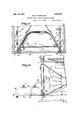
Fig. l is a sectional side elevation of one embodiment of the present invention, the
composite radio panel and sound modifier being; in full open position;
Fig. 2 is a top plan View, in section, of the elements shown in Fig. 1, the composite panel and sound modifier being in closed position; v
Fig. 3 is a sectional view taken on the line 83 of Fig. 1; i
Figs. 4 and 5 are detail end and side views, respectively, illustrating one manner in which the guides for the panel supporting arms may be formed.
Fig.6 is a sectional side view of another embodiment of the present invention.
Referring particularly to Figs 1 to 5 in elusive, the apparatus constituting the subject matter of the present invention is mounted in a cabinet of any suitable type: as for example, an upright talking machine cabinet which may comprise a front wall or panel 1, provided with a suitable opening 2, and end panels or side walls 8. An amplifier or horn A is mounted in any well known manner in the cabinet with the open end thereof adjacent the opening 2 in the front wall 1. The specific features of the amplifier, or horn, and the receiver of the telephone type (not shown) associated therewith, constitute no part of the present invention, but if desired the horn may be of the type employed in talking machines or may be the horn of a talking machine.
Preferably, a number of vertically disposed strengthening strips or wooden cleats '5 are suitably secured to the inner surface of walls 3, and attached to said strips as by means of screws 6 is a guide 7 composed of upper and lower supporting brackets or flanges 7 and 7 which are disposed in substantially horizontal planes. The guide 7 is formed of a metal strip which is bent, parallel to its opposite side edges through an angle of ninety degrees, and the bent portions are further bent longitudinally adja cent their edges to form L-shaped flanges, the shortlegs of the Us being in a plane parallel to the main portion of the strip. Rounded ears 7 are cut from the main por tion adjacent the opposite ends of the strip, and'these ears are bent through an angle of 180 so that the ears extend on opposite parts throughout the iii;
leg of the line being substantially at the transverse bend. The tab 7 termed by this cut is bent inwardly through an angle of 90 so that it fills up the channel termed by the lower L-shaped flange. The lug T left by the L-shapedv cut similarly closes the end of the channel formed by the upper L-shaped flange. Slidably mounted in each guide 7, the opposite flanges 7 and 7" of which constitute runways or tracks, is a ianel su ortin arm 8, and nivotall secured, as by means oi? a rivet S), to the inner end 01"? each arm, is a roller having a diameter materially greater-than the width of the arm, which has rolling contact with the inner surfaces ot' the L-shaped flanges of the guide 7 The trout end of each arm has sliding engagement with the longitudinally bent tab 7 and lug 7 so that excessive play of the arm is prevented. In order-to limit the outward movement of arms 8, a transversely extending pin 11 (Fig; 2) may be provided in the lower flange 7 of each guide in the path of the roller 10.
The composite radio panel and sound modifier is suitably secured to the outer ends of the supporting arms 8 whereby the same may be moved parallel to itself to modi'ty the sounds emitted from the horn l. As shown, the outer ends 01? the arms 8 are provided with vertically disposed portions 8 constituting a T-shaped head therefor, and secured to the latter, as bymeans of. screws 12, is a rectangular frame 13 that may be formed of wood. This trai'ne is shown as generally pentagonal in cross section, with the outer, rear sides thereof cut at an angle to the axis of the horn substantially equal to that of the inner faces oi the mouth portion 0t horn 4., and secured to the sides so shaped is a metal housing 141; which is generally 'illlSil'O-COI]lCttl and shaped. so as to parallel the in ncr tacos ot the mouth portion of the horn, the rear end of the housing being suitably rounded and closed.
The housing 14; constitutes an enclosure for a radio receiving instrument provided with a radio panel tor mounting the control elements. This heut-iing protects the elements of the inst-run'ient mounted on the rear of the panel trom dust and moisture. It is to be expressly understood, however, hat the use of this housing is not essential. As shown, a frame 15 is secured at its perimeter, and in a substantially vertical position, to the inner surtace oi the housing 14.
at a suitable point intermediate the open and closed ends 01 the latter. Attached in any suitable way to the trame 15 is a panel 16 on which are mounted control elements 17 for the radio receiving instrument, the remainder of the mechanism (not shown) mounted on the rear face of the panel, being completely enclosed by the housing lei.
Preferably a swinging door 18 is provided as a cover for the radio panel, which door may be pivoted about a horizontal axis to the lower side of. frame 13, as at 19. A support 20, pivoted at one end to a l'lracltet 21 that is rigidly attached to the door 18, is provided with an elongated slot which slidably engages a pin which is secured in a suitable manner to the housing 14, and constitutes means for holding said door in open or horizontal position. Means are provided whereby the various electrical connections, that may be employed between the elements of: the receiving instrument enclosed in the housing 14. or carried by the panel, and other elements oil the device, such as the telephone unit tor the horn, the battcries, ground, antenna, ctc., are not dis turbed by movement of the radio panel to ward and away i'rom the. horn. As shown, a rigid member 23 is fixedly attached, by means of screws 24, to the lower surface of housing 14.- and extends inwardly through an opening 25 provided in the "all of the born 4. The flexible wires or members constituting the electrical leads extend through a longitudinal opening 23 in the member 2 and are therefore protected by the latter during the movement of the housing ti to its various positions OfeldjUStll'lGnt.
Movement of the radio panel 16 and the elements associated therewith toward and away from the horn 4 varies the volume of sounds emitted from the amplifier or horn and. modulates such sounds, by varying the width of the passage between the housing 14k or panel 16 and the horn mouth The door 18 gives access to the control members 17 which latter are in a convenient position for acljustn'ient regardless of the position of the panel 155.
In Fig. 6 there is illustrated another enibodimcnt of the invention wherein a radio receiving instrument. including a panel 16, control members 17 and a suitable housing 26, mounted for pivotal instead of rectilinear movement. As shown a swinging. door 27 is suitably hinged as at 28, to the front wall 1 (it the cabinet,- and' carries the panel 16 control members 17 and housing 2-6. Normally the panel 16 occupies a vertical position within the horn 4. as shown in dotted lines, where together with the housing 26 and door 27 it constitutes a closure for said horn.
Suitable means are provided for holding the panel 1.6 n one or more positions suit- Ian able for adjusting the control members 17. In the form shown the door may swing'to a horizontal position and means are provided for preventing the panel 14 moving past this position. To this end, a rigid arcuate member 29, provided with an inwardly turned portion 29 at the inner end thereof, is secured at its outer end, as at 30, to the side of the door 27, and extends through a suitable slot or opening in a stop member 31 secured to the front wall 1.
The panel 16 may be swung to open position, where it constitutes a sound modifier in a manner well understood in the art, and when in horizontal position the inwardly turned portion .29 engages the stop 31 and maintains the panel in a convenient operating position.
It will thus be perceived that there is provided a novel sound modifier, constituted by a radio panel or its housmg, for varying the characteristics of sounds emitted from an amplifier. The device is very compact and pleasing in appearance and the control. members are readily accessible for adjustment. The apparatus is particularly adapted for combination with a talking machine of the type wherein a common horn is employed for the amplification of both mechanically and electrically generated sounds. Movement of the sound modifier does not tend to wear away or destroy the insulation of the electrical lead wires, nor to disrupt the same, and the elements of the receiving instrument are protected from dust and moisture.
While two embodiments of the inventive idea have been described with considerable particularity, it is to be understood that the invention is not limited thereto, since various changes may be made in the same 7 within the limits of the appended claims.
What is claimed is 1. A composite radio panel and sound modifier comprising, in combination with a cabinet, a horn mounted in said cabinet, a vertically disposed panel, control elements mounted on the face of said panel, and means for movably securing said panel to the cabinet whereby said panel may be moved to vary the sounds emitted from said horn, said panel being adapted when not in use to occupy position within said horn with said control elements in protected relation and affording ready access to said con-- trol elements when the'latter are to be placed in service.
2. A device of the class described comprising, in combination with a cabinet having an opening therein, a horn having its discharge end positioned adjacent said openings, a panel in the horn, means for movably securing the panel to the cabinet whereby the panel may be moved to vary the volume of sounds emitted from said horn,
and control means secured to the panel, said control means normally being in protected relation but adapted for ready access when the same are to be placed in service.
3. A device of the class described comprising, in combination with a cabinet having an opening therein, a horn having its discharge end positioned adjacent said opening, a housing normally spaced from the discharge end of said horn, means for movably securing said housing to the cabinet, whereby it may be moved to close the discharge end of said horn, said housing including a radio panel constituting a sound. modifier, and radio control elements mounted on said panel with said elements in protected relation and affording ready access thereto when the same are to be placed in service.
1- A deviceof the class described comprising in combination with a cabinet, horn in said cabinet, brackets constituting runways secured to the cabinet, arms slidably engaging said brackets, a vertically disposed panel securcd to said arms and normally positioned within the horn, and control elements carried by said panel.
5. A device of the class described comprising in combination with a cabinet having an opening therein, a horn in the cabinet positioned with its discharge end adjacent said opening, means constituting guideways secured to the cabinet, arms slidably engaging said guideways, a frame secured to said arms, a panel normally positioned in the horn, means for securing said panel to said frame, and control members carried by the panel.
6. A device of the class described comprising in combination with a cabinet having an opening therein, a horn in the cabinet positioned with its discharge end adjacent said opening, means constituting guideways secured to the cabinet, arms slidably engaging said guideways, a frame secured to said arms, a panel normally positioned in the horn, a housing for securing the panel to said frame, and control members carried by the panel.
7 A device of the class described compris ing, in combination with a cabinet having an opening therein, a. horn in the cabinet positioned with its open end adjacent said opening, horizontally disposed, members socured to the cabinet, arms having sliding en gagement with said members, a frame secured to said arms, a housing including a panel constituting a sound modifier and. secured to said frame, and a movable door secured to the frame.
8. A device of the class described comprising, in combination with a cabinet having an opening therein, a horn having its open end positioned adjacent said opening, a movably mounted panel constituting a sound modifier positioned in said horn, means for securing the panel to the cabinet whereby said panel may be moved parallel to itself, and rigid protective means secured to the panel and extending through an opening in the horn.
9. A device 01" the class described comprising in combination with a cabinet having an opening therein, amplifying means, positioned adjacent said opening, a panel posi tioned in said means, means for securing the panel to the cabinet whereby the panel may be moved parallel to itself to modify sounds emitted from the amplifying means, a rigid protective member secured to said panel and extending through an opening inv said amplit'ying means, and means enclosing said panel and movable therewith.
10. A composite radio panel and sound modifier comprising. in combination with a cabinet, a horn mounted in said cabinet, a vertically disposed panel. adapted when not in use to occu iiy a position within said horn, control. elements mounted on the face of said panel, and means "for movabl'y securing said panel to the cabinet whereby said panel may be moved to vary the sounds emitted from said horn, said panel being adapted when in use to be moved outwardly with respect to the horn, said control elements normally being in protected relation and adapted for ready access when the same are to be placed in service.
11. A device of the class described coinprising, in combination with a cabinet having' an opening therein, a horn in the cabinet positioned with its open end adjacent said opening,horizontally disposed men'lbcrs secured to the cabinet, arms having slidingengagement with said members, ttrict-ion reducing elements operativel interposed between said arms and said horizontally disposed members, a frame secured to said arms, a housing including a panel. constituting a sound modifier secured to said t'anie, and radio control elements mounted on said panel, said cont-rel elements normally being: in protected position and adapted for ream access when the same are to be placed in service.
In testimony whereof I hav: signed this specification.
WILLIAM B. QTEVENSON.
Priority Applications (1)
| Application Number | Priority Date | Filing Date | Title |
|---|---|---|---|
| US51502A US1652257A (en) | 1925-08-20 | 1925-08-20 | Composite radiopanel and sound modifier |
Applications Claiming Priority (1)
| Application Number | Priority Date | Filing Date | Title |
|---|---|---|---|
| US51502A US1652257A (en) | 1925-08-20 | 1925-08-20 | Composite radiopanel and sound modifier |
Publications (1)
| Publication Number | Publication Date |
|---|---|
| US1652257A true US1652257A (en) | 1927-12-13 |
Family
ID=21971693
Family Applications (1)
| Application Number | Title | Priority Date | Filing Date |
|---|---|---|---|
| US51502A Expired - Lifetime US1652257A (en) | 1925-08-20 | 1925-08-20 | Composite radiopanel and sound modifier |
Country Status (1)
| Country | Link |
|---|---|
| US (1) | US1652257A (en) |
Cited By (5)
| Publication number | Priority date | Publication date | Assignee | Title |
|---|---|---|---|---|
| US2567829A (en) * | 1947-03-06 | 1951-09-11 | Suthann Robert Andree | Combined cabinet and chassis for mounting electrical components |
| US4055206A (en) * | 1975-05-14 | 1977-10-25 | Griffin Carl W | Composite shop trailer |
| US20040135476A1 (en) * | 2003-01-07 | 2004-07-15 | Alan Gillengerten | Audio visual system and apparatus |
| US20050146251A1 (en) * | 2003-09-17 | 2005-07-07 | Alan Gillengerten | Audio visual system |
| US20100296686A1 (en) * | 2009-05-22 | 2010-11-25 | Canon Kabushiki Kaisha | Speaker apparatus |
-
1925
- 1925-08-20 US US51502A patent/US1652257A/en not_active Expired - Lifetime
Cited By (7)
| Publication number | Priority date | Publication date | Assignee | Title |
|---|---|---|---|---|
| US2567829A (en) * | 1947-03-06 | 1951-09-11 | Suthann Robert Andree | Combined cabinet and chassis for mounting electrical components |
| US4055206A (en) * | 1975-05-14 | 1977-10-25 | Griffin Carl W | Composite shop trailer |
| US20040135476A1 (en) * | 2003-01-07 | 2004-07-15 | Alan Gillengerten | Audio visual system and apparatus |
| US20050146251A1 (en) * | 2003-09-17 | 2005-07-07 | Alan Gillengerten | Audio visual system |
| US6997525B2 (en) * | 2003-09-17 | 2006-02-14 | Alan Gillengerten | Audio visual system |
| US20100296686A1 (en) * | 2009-05-22 | 2010-11-25 | Canon Kabushiki Kaisha | Speaker apparatus |
| EP2254347A3 (en) * | 2009-05-22 | 2013-01-02 | Canon Kabushiki Kaisha | Speaker apparatus |
Similar Documents
| Publication | Publication Date | Title |
|---|---|---|
| US1652257A (en) | Composite radiopanel and sound modifier | |
| GB656732A (en) | Improvements in or relating to loud speakers | |
| US2196342A (en) | Acoustic compensator | |
| US2247171A (en) | Radio-phonograph combination | |
| US1589408A (en) | Protector for acoustic apparatus | |
| US3707201A (en) | Cabinet-mounted speaker system | |
| US2160283A (en) | Radio cabinet | |
| US1752526A (en) | Sound amplifier | |
| US2631077A (en) | Radio-phonograph combination receiver cabinet construction | |
| US1635837A (en) | Combination phonograph and radio cabinet | |
| US2649164A (en) | Cabinet for sound translating apparatus | |
| US2200297A (en) | Combined phonograph and radio | |
| US3301956A (en) | Sound system for banking service equipment | |
| US1643284A (en) | Sound amplifier | |
| US1615434A (en) | Tone chamber | |
| US1820996A (en) | Sound amplifying system | |
| US1407574A (en) | Phonograph resonance box | |
| US1793753A (en) | Radiotable | |
| US1796551A (en) | One-hand lid support | |
| US1315989A (en) | Soiwd-kepbodxroibro ucachihes | |
| USRE13069E (en) | Talking-machine | |
| US2627556A (en) | Radio phonograph cabinet | |
| US1456039A (en) | Phonograph | |
| US2286742A (en) | Sound-producing and sound-reproducing apparatus | |
| JP5151225B2 (en) | Game machine |