EP3232688A1 - Apparatus and method for providing individual sound zones - Google Patents
Apparatus and method for providing individual sound zones Download PDFInfo
- Publication number
- EP3232688A1 EP3232688A1 EP16164984.3A EP16164984A EP3232688A1 EP 3232688 A1 EP3232688 A1 EP 3232688A1 EP 16164984 A EP16164984 A EP 16164984A EP 3232688 A1 EP3232688 A1 EP 3232688A1
- Authority
- EP
- European Patent Office
- Prior art keywords
- audio
- signals
- signal
- initial
- initial audio
- Prior art date
- Legal status (The legal status is an assumption and is not a legal conclusion. Google has not performed a legal analysis and makes no representation as to the accuracy of the status listed.)
- Withdrawn
Links
Images


Classifications
-
- H—ELECTRICITY
- H04—ELECTRIC COMMUNICATION TECHNIQUE
- H04S—STEREOPHONIC SYSTEMS
- H04S3/00—Systems employing more than two channels, e.g. quadraphonic
- H04S3/008—Systems employing more than two channels, e.g. quadraphonic in which the audio signals are in digital form, i.e. employing more than two discrete digital channels
-
- H—ELECTRICITY
- H04—ELECTRIC COMMUNICATION TECHNIQUE
- H04S—STEREOPHONIC SYSTEMS
- H04S7/00—Indicating arrangements; Control arrangements, e.g. balance control
-
- H—ELECTRICITY
- H04—ELECTRIC COMMUNICATION TECHNIQUE
- H04S—STEREOPHONIC SYSTEMS
- H04S7/00—Indicating arrangements; Control arrangements, e.g. balance control
- H04S7/30—Control circuits for electronic adaptation of the sound field
-
- H—ELECTRICITY
- H04—ELECTRIC COMMUNICATION TECHNIQUE
- H04R—LOUDSPEAKERS, MICROPHONES, GRAMOPHONE PICK-UPS OR LIKE ACOUSTIC ELECTROMECHANICAL TRANSDUCERS; DEAF-AID SETS; PUBLIC ADDRESS SYSTEMS
- H04R2499/00—Aspects covered by H04R or H04S not otherwise provided for in their subgroups
- H04R2499/10—General applications
- H04R2499/13—Acoustic transducers and sound field adaptation in vehicles
-
- H—ELECTRICITY
- H04—ELECTRIC COMMUNICATION TECHNIQUE
- H04S—STEREOPHONIC SYSTEMS
- H04S2400/00—Details of stereophonic systems covered by H04S but not provided for in its groups
- H04S2400/13—Aspects of volume control, not necessarily automatic, in stereophonic sound systems
-
- H—ELECTRICITY
- H04—ELECTRIC COMMUNICATION TECHNIQUE
- H04S—STEREOPHONIC SYSTEMS
- H04S2400/00—Details of stereophonic systems covered by H04S but not provided for in its groups
- H04S2400/15—Aspects of sound capture and related signal processing for recording or reproduction
-
- H—ELECTRICITY
- H04—ELECTRIC COMMUNICATION TECHNIQUE
- H04S—STEREOPHONIC SYSTEMS
- H04S2420/00—Techniques used stereophonic systems covered by H04S but not provided for in its groups
- H04S2420/11—Application of ambisonics in stereophonic audio systems
-
- H—ELECTRICITY
- H04—ELECTRIC COMMUNICATION TECHNIQUE
- H04S—STEREOPHONIC SYSTEMS
- H04S2420/00—Techniques used stereophonic systems covered by H04S but not provided for in its groups
- H04S2420/13—Application of wave-field synthesis in stereophonic audio systems
Definitions
- the present invention relates to audio signal processing and, in particular, to an apparatus and method for providing individual sound zones.
- multizone reproduction Reproducing different acoustic scenes in multiple sound zones located nearby without acoustic barriers in between is a well-known task in audio signal processing, which is often referred to as multizone reproduction (see [1]). From the technical point of view, multizone reproduction is closely related to loudspeaker beamforming or spotforming (see [2]) when nearfield scenarios are considered, where the loudspeaker array aperture may also enclose the listener.
- a problem in a multizone reproduction scenario may, for example, be to provide substantially different acoustic scenes (e.g. different pieces of music or audio content of different movies) to the listeners occupying individual sound zones.
- substantially different acoustic scenes e.g. different pieces of music or audio content of different movies
- FIG. 2 A simplified ideal example of multizone reproduction is shown in Fig. 2 , where the two zones 221, 222 receive the signals u 1 ( k ) and u 2 ( k ) of two signal sources 211, 212, respectively, without interference of the other source and k being the time instant. It should be noted that this scenario is only a placeholder for more complex scenarios, where multichannel audio is provided to an arbitrary number of zones. However, the simple example shown in Fig. 2 is sufficient for the explanations in the following.
- Fig. 3 illustrates a reproduction of multiple signals in reality.
- y 1,2 ( k ) and y 2,1 ( k ) are considered to be unwanted interfering signal components, in contrast to the desired components y 1,1 ( k ) and y 2,2 ( k ).
- u 1 ( k ) and u 2 ( k ) describe entirely different acoustic scenes, only a very small contribution of u 2 ( k ) in y 1 ( k ) compared to the contribution of u 1 ( k ) in y 1 ( k ) is acceptable. The same holds for y 2 ( k ) with reversed indices.
- a straightforward way to achieve this is to design the loudspeaker setup such that h 1,1 ( k ) and h 2,2 ( k ) exhibit a higher energy, compared to h 1,2 ( k ) and h 2,1 ( k ), which describe cross-zone reproduction.
- One example for this would be to use loudspeakers located nearby the listeners ( US 2003103636 , US 2003142842 ), where using headphones can be seen as an extreme case of such a setup.
- placing loudspeakers too close to the listeners is often unacceptable, because this can interfere with the listener's movement, such that this approach is limited in practical applications.
- Another approach is to utilize a loudspeaker array in conjunction with suitable prefilters for a personalized audio reproduction.
- Fig. 4 illustrates a minimal example of multizone reproduction with arrays.
- Fig. 4 illustrates a rudimentary setup with two signal sources 211, 212, two loudspeakers and two zones 221, 222.
- the example of Fig. 4 is a placeholder for more complex scenarios that occur in real-world applications.
- the amount of cross-zone reproduction is determined by the cascade of the prefilters G ( K ) 413, 414 and the impulse responses H ( k ) 417 and not only by H ( k ) 417.
- h 1,2 ( k ) and h 2,1 ( k ) do not necessarily have to be small in magnitude in order to achieve a considerable cross-zone attenuation.
- Fig. 6 illustrates a general signal model of multizone reproduction with arrays.
- the signal sources 610, the prefilters 615, the impulse responses 417 and the sound zones 221, 222 are depicted.
- multizone reproduction is generally not limited to providing two signals to two zones.
- the numbers of sources, loudspeakers and listening zones can be arbitrary.
- the following explanations and definitions can be used for a general scenario with N S signal sources, N L loudspeakers, and N M considered positions in the N Z listening zones. In such a scenario, it is possible that multiple signals are reproduced in an individual zone to achieve a spatial sound reproduction.
- the corresponding signal model is shown in Fig. 6 , where "Zone 1" 221 is supplied with the signals y 1 ( k ) and y 2 ( k ).
- signal source 211 shall be reproduced in sound zone 221, but not in sound zone 222.
- signal source 212 shall be reproduced in sound zone 222, but not in sound zone 221.
- the prefilters are typically designed such that the ratio between the acoustic energy radiated into the bright zones and the acoustic energy radiated into the dark zones is maximized.
- This ratio is often termed acoustic contrast (see [3]) and can be measured by defining B q ( k ) and D q ( k ), which capture the room impulse responses from each loudspeaker, to the considered sampling points in the bright and dark zones, respectively. Since this assignment is different for every source signal, both matrices are dependent on the source signal index q .
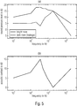
- FIG. 5 An example of the reproduction levels in bright and dark zone with resulting acoustic contrast is shown in Fig. 5 .
- Fig. 5 illustrates in (a) an exemplary reproduction level in bright and dark zone, and illustrates in (b) a resulting acoustic contrast.
- H k B q k + D q k ⁇ q , k .
- the minimum inter-loudspeaker distance implies an upper frequency limit. This is because the sampling theorem, see:
- the enclosure where the multiple sound zones should be created can influence the achieved radiation pattern itself.
- models can be found to analytically consider the enclosure geometry in the design of directional loudspeakers or prefilters for loudspeaker array reproduction.
- This is no longer possible when the enclosure exhibits a (general) curvature, when arbitrarily shaped obstacles are placed in the enclosure, or when the dimensions of the enclosure are in the order of magnitude of the wavelength.
- Such a setup exists, e.g., in a car cabin and will be referred to as a complex setup in the following. Under such conditions, exciting a controlled sound field by directional loudspeakers or electrically steered arrays is very challenging because of the sound reflected from the enclosure that cannot be exactly modeled. Under such conditions, even non-directional individually driven loudspeakers may effectively exhibit an uncontrolled directional pattern.
- US 2005/0152562 A1 (see [8]) relates to in-car surround sound reproduction with different operation modes related to different loudness patterns on the individual seats and different equalization patterns.
- US 2013/170668 A1 (see [9]) describes mixing an announcement sound to an entertainment signal. The mix between both signals is individual for each of two zones.
- US 2008/0071400 A1 discloses signal processing depending on source or content information considering two different signals to relief the driver from being "acoustically overloaded”.
- US 2006/0034470 A1 (see [11]) relates to equalization, compression, and "mirror image” equalization to reproduce audio in high-noise conditions with increased quality.
- US 2011/0222695 A1 discloses audio compression of subsequently played audio tracks, also with considering the ambient noise and psychoacoustic models.
- US 2015/0256933 A1 discloses a balance level of telephone and entertainment content to minimize acoustic leakage of content.
- US 6,674,865 B1 (see [15]) relates to automatic gain control, for hands-free telephony.
- US 2012/0140945 A1 (see [17]) relates to explicit sound zones implementation. High frequencies are reproduced by a loudspeaker, low frequencies use constructive and destructive interference by manipulating amplitude phase and delay. To determine how amplitude, phase, and delay have to be manipulated, [17] proposes to use special techniques, the "Tan Theta"-method or solving an eigenvalue problem.
- US 2008/0273713 A1 discloses sound zones, array of speakers located near each seat, wherein a loudspeaker array is explicitly assigned to each of the zones.
- US 2004/0105550 A1 (see [19]) relates to sound zones, directional close to head, non-directional away from listener.
- US 2005/0190935 A1 (see [21]) relates to headrest or seat back loudspeakers for personalized playback.
- US 2008/0130922 A1 discloses sound zones implementation with directional loudspeakers near front seat, non-directional loudspeakers near back seat and signal processing such that front and back cancel to leakage of each other.
- US 2010/0329488 A1 (see [23]) describes sound zones in a vehicle with at least one loudspeaker and one microphone associated with each zone.
- DE 10 2014 210 105 A1 (see [24]) relates to sound zones realized with binaural reproduction, also using crosstalk-cancellation (between ears), and also to a reduction of cross-talk between zones.
- US 2011/0286614 A1 discloses sound zones with binaural reproduction based on crosstalk-cancellation and head tracking.
- US 2013/0230175 A1 (see [27]) relates to sound zones, explicitly using microphones.
- WO 2016/008621 A1 discloses a head and torso simulator.
- US 2008/0273712 A1 discloses a directional loudspeaker mounted to a vehicle seat.
- US 5,809,153 (see [31]) relates to three loudspeakers point in three directions with circuitry to use them as arrays.
- US 2003/0103636 A1 (see [33]) relates to a personalized reproduction and silencing and to headrest arrays to produce the sound field at listeners ears including silencing.
- US 2003/0142842 A1 (see [34]) relates to headrest loudspeakers.
- JP 5345549 (see [35]) describes parametric loudspeakers in front seats pointing back.
- US 2014/0064526 A1 (see [37]) relates to producing a binaural and localized audio signal to a user.
- US 2010/0046765 A1 (see [48]) and DE 10 2010 040 689 (see [49]) relate to an optimized cross-fade between subsequently reproduced acoustic scenes.
- WO 2007/098916 A1 (see [52]) describes reproducing a warning sound.
- US 2007/0286426 A1 (see [54]) describes the mixing of one audio signal (e.g. from a telephone) to another (e.g. music).
- US 5,018,205 (see [55]) relates to band-selective adjustment of gain in presence of ambient noise.
- JP 2003-255954 discloses active noise cancellation using loudspeakers located near listeners.
- the object of the present invention is to provide improved concepts for audio signal processing.
- the object of the present invention is solved by an apparatus according to claim 1, by a method according to claim 16 and by a computer program according to claim 17.
- An apparatus for generating a plurality of loudspeaker signals from two or more audio source signals is provided.
- Each of the two or more audio source signals shall be reproduced in one or more of two or more sound zones, and at least one of the two or more audio source signals shall not be reproduced in at least one of the two more sound zones.
- the apparatus comprises an audio preprocessor configured to modify each of two or more initial audio signals to obtain two or more preprocessed audio signals.
- the apparatus comprises a filter configured to generate the plurality of loudspeaker signals depending on the two or more preprocessed audio signals.
- the audio preprocessor is configured to use the two or more audio source signals as the two or more initial audio signals, or wherein the audio preprocessor is configured to generate for each audio source signal of the two or more audio source signals an initial audio signal of the two more initial audio signals by modifying said audio source signal. Moreover, the audio preprocessor is configured to modify each initial audio signal of the two or more initial audio signals depending on a signal power or a loudness of another initial audio signal of the two or more initial audio signals.
- the filter is configured to generate the plurality of loudspeaker signals depending on in which of the two or more sound zones the two or more audio source signals shall be reproduced and depending on in which of the two or more sound zones the two or more audio source signals shall not be reproduced.
- a method for generating a plurality of loudspeaker signals from two or more audio source signals is provided.
- Each of the two or more audio source signals shall be reproduced in one or more of two or more sound zones, and at least one of the two or more audio source signals shall not be reproduced in at least one of the two more sound zones.
- the method comprises:
- the two or more audio source signals are used as the two or more initial audio signals, or wherein for each audio source signal of the two or more audio source signals an initial audio signal of the two more initial audio signals is generated by modifying said audio source signal.
- Each initial audio signal of the two or more initial audio signals is modified depending on a signal power or a loudness of another initial audio signal of the two or more initial audio signals.
- the plurality of loudspeaker signals is generated depending on in which of the two or more sound zones the two or more audio source signals shall be reproduced and depending on in which of the two or more sound zones the two or more audio source signals shall not be reproduced.
- each of the computer programs is configured to implement one of the above-described methods when being executed on a computer or signal processor.
- Some embodiments provide a signal-dependent level modification to reduce the perceived acoustic leakage when using measures for directional reproduction of independent entertainment signals.
- Some of the embodiments are optionally employed in an automotive scenario, but are not limited to such a scenario.
- Some embodiments relate to concepts that provide individual audio content to listeners occupying the same enclosure without the use of headphones or alike. Inter alia, these embodiments differ from the state-of-the-art by a smart combination of different reproduction approaches with a signal-dependent preprocessing such that a large perceptual acoustic contrast is achieved while retaining a high level of audio quality.
- Some embodiments provide a filter design.
- Some of the embodiments employ additional signal-dependent processing.
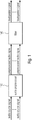
- Fig. 1 illustrates an apparatus for generating a plurality of loudspeaker signals from two or more audio source signals according to an embodiment.
- Each of the two or more audio source signals shall be reproduced in one or more of two or more sound zones, and at least one of the two or more audio source signals shall not be reproduced in at least one of the two more sound zones.
- the apparatus comprises an audio preprocessor 110 configured to modify each of two or more initial audio signals to obtain two or more preprocessed audio signals. Moreover, the apparatus comprises a filter 140 configured to generate the plurality of loudspeaker signals depending on the two or more preprocessed audio signals.
- the audio preprocessor 110 is configured to use the two or more audio source signals as the two or more initial audio signals, or wherein the audio preprocessor 110 is configured to generate for each audio source signal of the two or more audio source signals an initial audio signal of the two more initial audio signals by modifying said audio source signal.
- the audio preprocessor 110 is configured to modify each initial audio signal of the two or more initial audio signals depending on a signal power or a loudness of another initial audio signal of the two or more initial audio signals.
- the filter 140 is configured to generate the plurality of loudspeaker signals depending on in which of the two or more sound zones the two or more audio source signals shall be reproduced and depending on in which of the two or more sound zones the two or more audio source signals shall not be reproduced.
- the acoustic contrast perceived by the listeners shall be improved, which is dependent on the acoustic contrast as defined in Equation (14) above, but not identical to it. It shall be achieved that the acoustic contrast perceived by the listeners is increased rather than maximizing the contrast of acoustic energy.
- the perceived acoustic contrast will be referred to as subjective acoustic contrast, while the contrast in acoustic energy will be referred to as objective acoustic contrast in the following.
- Some embodiments employ measures to facilitate directional audio reproduction and measures to shape the acoustic leakage such that it becomes less noticeable.
- the apparatus of Fig. 7 further comprises two (optional) band splitters 121, 122 and four (optional) spectral shapers 131, 132, 133, 134.
- the apparatus may, e.g., further comprise two or more band splitters 121, 122 being configured to conduct band splitting on the two or more preprocessed audio signals to a plurality of band-splitted audio signals.
- the filter 140 may, e.g., be configured to generate the plurality of loudspeaker signals depending on the plurality of band-splitted audio signals.
- the apparatus may, e.g., further comprises one or more spectral shapers 131, 132, 133, 134 being configured to modify a spectral envelope of one or more of the plurality of band-splitted audio signals to obtain one or more spectrally shaped audio signals.
- the filter 140 may, e.g., configured to generate the plurality of loudspeaker signals depending on the one or more spectrally shaped audio signals.
- Fig. 7 a signal model of an implementation according to embodiments is shown.
- Fig. 7 illustrates multizone reproduction with arrays according to embodiments. This example has been chosen for conciseness, noting that the method is generally applicable to scenarios with N S signal sources, N L loudspeakers, and N Z listening zones, as described above.
- This preprocessing stage may, for example, in some embodiments implement a parallel processing for both signals (i.e., no mixing).
- this processing step does not constitute a LTI system (Linear Time-Invariant System). Instead, this processing block determines time-varying gains for all processed source signals, such that their difference in reproduction level is reduced.
- LTI system Linear Time-Invariant System
- the perceived acoustic leakage is proportional to the level difference between the scenes that are intentionally reproduced in the respective zones.
- reducing the level difference of the reproduced scenes will also reduce the perceived acoustic leakage and, hence, increase the subjective acoustic contrast.
- the (optional) band splitters 121, 122 realize the (optional) processing step band splitting, and split the signal into multiple frequency bands, just like an audio crossover would do in a multi-way loudspeaker.
- This band splitter unlike audio crossovers in a loudspeaker, it is only a second objective of this band splitter to maximize the radiated acoustic power.
- the primary objective of this band splitter is to distribute the individual frequency bands to individual reproduction measures such that the acoustic contrast is maximized, given certain quality constraints. For example, the signal w 1 ( k ) will later be fed to a single loudspeaker as signal x 1 ( k ).
- w 1 ( k ) would be high-pass filtered because the directivity of this loudspeaker will be low at low frequencies.
- w 2 ( k ) will later be filtered to obtain x 2 ( k ) and x 3 ( k ) such that the according loudspeakers are used as an electrically steered array.
- there can be more outputs of the band splitter such that the signals are distributed to multiple reproduction methods according to the needs of the application (see also below, where a loudspeaker-enclosure-microphone system according to embodiments is described).
- the measures for directional reproduction applied later will always exhibit a certain leakage from one zone to the other.
- This leakage can be measured as break down in acoustic contrast between the zones.
- these breakdowns can occur at multiple points in the frequency spectrum for each of the envisaged directional reproduction methods, which constitute a major obstacle in the application of those methods.
- timbre-variations are acceptable to a certain extent. These degrees of freedom can be used to attenuate contrast-critical frequency bands.
- the (optional) spectral shapers 131, 132, 133, 134 are designed in a way such that the signals reproduced later are attenuated in these parts of the frequency spectrum, where a low acoustic contrast is expected.
- the spectral shapers are intended to modify the timbre of the reproduced sound.
- this processing stage can also involve delays and gains such that the intentionally reproduced acoustic scene can spatially mask the acoustic leakage.
- the blocks denoted by G 1 ( k ) and G 2 ( k ) may, e.g., describe linear time-invariant filters that are optimized to maximize the objective acoustic contrast given subjective quality constraints.
- filters which include (but are no limited to) ACC, pressure matching (see [4] and [6]), and loudspeaker beamforming. It was found, that a least squared pressure matching approach as described below, when a prefilter according to embodiments is described, is especially suitable, when measured impulse responses are considered for the filter optimization. This can be a preferred concept for implementation.
- impulse responses are calculated to represent the free-field impulse responses from the loudspeakers to the microphones.
- the impulse responses are measured once such that no microphones are necessary during operation.
- the pressure matching approach prescribes a given magnitude and phase in the respective bright zone. This results in a high reproduction quality.
- Traditional beamforming approaches are also suitable when high frequencies should be reproduced.
- the block denoted by H ( k ) represents the LEMS, where each input is associated with one loudspeaker. Each of the outputs is associated with an individual listener that receives the superposition of all loudspeaker contributions in his individual sound zone.
- the loudspeakers that are driven without using the prefilters G 1 ( k ) and G 2 ( k ) are either directional loudspeakers radiating primary into one sound zone or loudspeaker that are arranged near (or in) an individual sound zone such that they primarily excite sound in that zone. For higher frequencies, directional loudspeakers can be build without significant effort. Hence, these loudspeakers can be used to provide the high-range frequencies to the listeners, where the loudspeakers do not have to be placed directly at the listeners ears.
- preprocessing according to embodiments are described.
- an implementation of the block denoted by "Preprocessing" in Fig. 7 is presented.
- the following explanations concentrate on only one mono signal per zone.
- a generalization to multichannel signals is straightforward.
- some embodiments exhibit multichannel signals per zone.
- Fig. 8 illustrates a sample implementation of an audio preprocessor 110 and a corresponding signal model according to an embodiment.
- the two input signals u 1 ( k ) and u 2 ( k ) are intended to be primarily reproduced in Zone 1 and Zone 2, respectively.
- the two input signals u 1 ( k ) and u 2 ( k ) are also referred to as audio source signals in the following.
- the power of both input signals, u 1 ( k ) and u 2 ( k ) (the audio source signals) is normalized to alleviate the parameter choice for the following processing.
- the audio preprocessor (110) may, e.g., be configured to generate the two more initial audio signals d 1 ( k ) and d 2 ( k ) by normalizing a power of each of the two or more audio source signals u 1 ( k ) and u 2 ( k ).
- the obtained power estimates b 1 ( k ) and b 2 ( k ) typically describe a long-term average, in contrast to the estimators used in a later stage that are typically considering a smaller time span.
- the update of b 1 ( k ) and b 2 ( k ) can be connected with an activity detection for u 1 ( k ) and u 2 ( k ), respectively, such that the update of b 1 ( k ) or b 2 ( k ) is held, when there is no activity in u 1 ( k ) or u 2 ( k ) .
- the signals c 1 ( k ) and c 2 ( k ) may, e.g., be inversely proportional to b 1 ( k ) and b 2 ( k ), respectively, such that a multiplication of c 1 ( k ) and c 2 ( k ) with u 1 ( k ) and u 2 ( k ), respectively, yields the signals, d 1 ( k ) and d 2 ( k ) that would exhibit comparable signal power. While using this first stage is not absolutely necessary, it ensures a reasonable working point for the relative processing of the signals d 1 ( k ) and d 2 ( k ), which alleviates finding suitable parameters for the following steps. It should be noted that if multiple instances of this processing block are placed after the "Band splitter” blocks or the "Spectral shaper" blocks, the power normalization has still to be applied before the "Band splitter” blocks.
- the two signals d 1 ( k ) and d 2 ( k ) that are supposed to be scaled and reproduced, are also referred to as initial audio signals in the following.
- the audio preprocessor 110 may, e.g., configured to generate for each audio source signal of the two or more audio source signals u 1 ( k ), u 2 ( k ) an initial audio signal of the two more initial audio signals d 1 ( k ), d 2 ( k ) by modifying said audio source signal, e.g., by conducting power normalization.
- the audio preprocessor 110 may, e.g., be configured to use the two or more audio source signals u 1 ( k ), u 2 ( k ) as the two or more initial audio signals d 1 ( k ), d 2 ( k ).
- the two signals d 1 ( k ) and d 2 ( k ) may, e.g., be fed to further loudness estimators, e.g., of the audio preprocessor 110, which provide the signals e 1 ( k ) and e 2 ( k ), respectively.
- the value of f ( x, y ) may, e.g., also be monotonically increasing with the ratio y / x .
- the factors g ' 1 ( k ) and g ' 2 ( k ) are then used to scale the signals d 1 ( k ) and d 2 ( k ), respectively, to obtain the output signals h 1 ( k ) and h 2 ( k ).
- the output signals h 1 ( k ) and h 2 ( k ) may, e.g., be fed into one or more modules which are configured to conduct multizone reproduction, e.g., according to an arbitrary multizone reproduction method.
- the audio preprocessor 110 may, e.g., be configured to modify each initial audio signal of the two or more initial audio signals depending on the signal power or the loudness of another initial audio signal of the two or more initial audio signals by modifying said initial audio signal of the two or more initial audio signals depending on a ratio of a first value ( v ) to a second value (x).
- the second value (x) may, e.g., depend on the signal power of said initial audio signal
- the first value ( y ) may, e.g., depend on the signal power of said another initial audio signal of the two or more initial audio signals.
- the second value ( x ) may, e.g., depend on the loudness of said initial audio signal
- the first value ( y ) may, e.g., depend on the loudness of said another initial audio signal of the two or more initial audio signals.
- the audio preprocessor 110 may, e.g., be configured to modify each initial audio signal of the two or more initial audio signals depending on the signal power or the loudness of another initial audio signal of the two or more initial audio signals by determining a gain for said initial audio signal and by applying the gain on said initial audio signal.
- the audio preprocessor 110 may, e.g., be configured to determine the gain depending on the ratio between the first value and the second value, said ratio being a ratio between the signal power of said another initial audio signal of the two or more initial audio signals and the signal power of said initial audio signal as the second value, or said ratio being a ratio between the loudness of said another initial audio signal of the two or more initial audio signals and the loudness of said initial audio signal as the second value.
- the audio preprocessor 110 may, e.g., be configured to determine the gain depending on a function that monotonically increases with the ratio between the first value and the second value.
- none of the signals u 1 ( k ), d 1 ( k ), or h 1 ( k ) is mixed to any of the signals u 2 ( k ), d 2 ( k ), or h 2 ( k ).
- u 1 ( k,l ) is assumed to comprise one or more audio channels.
- L indicates the number of audio channels of u 1 ( k ).
- ⁇ 1 may, e.g., be close to 1.
- ⁇ 1 may, e.g., be in the range 0.9 ⁇ ⁇ 1 ⁇ 1.
- u 1 ( k ), for example, comprises two or more channels.
- the value e 2 ( k ) has also to be determined as described above.
- the actual method to determine e 2 ( k ), as well as the parameters, may differ from those chosen for e 1 ( k ) (for example, depending on the needs of the application).
- the actual gain g' 1 ( k ) can, e.g., be determined similar to the gaining rule that would be used for a conventional audio compressor, see:
- T 1 defines the compression threshold in dB and R the compression ratio, as used in a standard audio compressor.
- 1 ⁇ R ⁇ 100 For example, 1 ⁇ R ⁇ 100.
- T 2 ⁇ T 1 combine both gaining rules.
- the resulting rule to obtain g' 1 ( k ) and g' 2 ( k ) can be any combination of upward and downward compressors, where practical implementations will typically require setting bound to the considered ranges of e 1 ( k ) and e 2 ( k ).
- the audio preprocessor 110 may, e.g., be configured to modify an initial audio signal of the two or more initial audio signals depending on the signal power or the loudness of another initial audio signal of the two or more initial audio signals by determining a gain g' 1 ( k ) for said initial audio signal and by applying the gain g' 1 ( k ) on said initial audio signal, and the audio preprocessor 110 may, e.g., be configured to determine the gain g' 1 ( k ) according to one or more of the above formulae.
- the branch of the signals e 1 ( k ) and e 2 ( k ) that is fed to the respectively opposite side may, e.g., be filtered through a filter describing the actual acoustic coupling of the two zones.
- the power estimators may, e.g., operate on signals that have been processed by a weighting filter, for example, that have been processed by a weighting filter described in:
- the power estimators may, e.g., be replaced by loudness estimators as, e.g., described by ITU-R Recommendation BS.1770-4. This will allow for an improved reproduction quality because the perceived loudness is better matched by this model.
- a level threshold may, e.g., be used to exclude silence from being taken into account for the estimates b 1 ( k ) and b 2 ( k ) in the absolute power normalization.
- a positive time-derivative of the separately estimated power can be used as an indicator for activity of the input signals u 1 ( k ) and u 2 ( k ).
- the estimates b 1 ( k ) and b 2 ( k ) are then only updated when activity is detected.
- this block may, e.g., be realized as a digital audio crossover, for example, as a digital audio crossover as described in:
- the desired frequency response of the input to output paths may, e.g., be a band pass with a flat frequency response in the pass band and a high attenuation in the stop band.
- the borders of pass bands and stop bands are chosen depending on the frequency range in which the reproduction measures connected to individual outputs can achieve a sufficient acoustics contrast between the respective sound zones.
- Fig. 9 illustrates an exemplary design of the one or more band splitters according to embodiments, wherein (a) illustrates acoustic contrast achieved by different reproduction methods, and wherein (b) illustrates a chosen magnitude response of the audio crossover.
- Fig. 9 illustrates an exemplary design of the filter magnitude response in relation to the achieved acoustic contrast.
- the spectral shaper may, e.g., be configured to modify a spectral envelope of an audio signal depending on the acoustic contrast.
- band splitters may be employed to realize the actual implementation of the one or more band splitters.
- some embodiments employ FIR filters
- other embodiments employ an IIR filter
- further embodiments employ analog filters.
- Any possible concept for realizing band splitters may be employed, for example any concept that is presented in general literature on that topic.
- Some of the embodiments may, for example, comprise a spectral shaper for conducting spectral shaping.
- spectral shaping is conducted on an audio signal, the spectral envelope of that audio signal may, e.g., modified and a spectrally-shaped audio signal may, e.g., be obtained.
- Spectral shapers constitute filters that exhibit frequency responses similar to those known for equalizers, such as combinations of first-order or second-order filters, see:
- Spectral filters consider the maximum spectral distortion that will be accepted by the listener, and the spectral filters are designed such they attenuate those frequencies which are known to produce acoustic leakage.
- a notch filter with a small bandwidth is applied to a broadband audio signal
- the listeners will only perceive a small difference, if any.
- a peak filter with the same bandwidth is applied to the same signal, the listeners will most likely perceive a considerable difference.
- Embodiments are based on the finding that this fact can be exploited because a bandlimited breakdown in acoustic contrast results in a peak in acoustic leakage (see Fig. 5 ). If the acoustic scene reproduced in the bright zone is filtered by an according notch filter, it will most likely not be perceived by the listeners in this zone. On the other hand, the peak of acoustic leakage that is perceived in the dark zone will be compensated by this measure.
- FIG. 10 An example of the corresponding filter response is shown in Fig. 10 .
- Fig. 10 illustratres an exemplary design of the spectral shapers according to embodiments, wherein (a) illustrates acoustic contrast achieved by a specific reproduction method, and wherein (b) illlustrates a chosen magnitude response of the spectral shaping filter.
- the filter 140 is configured to generate the plurality of loudspeaker signals depending on in which of the two or more sound zones the two or more audio source signals shall be reproduced and depending on in which of the two or more sound zones the two or more audio source signals shall not be reproduced.
- a filter 140 e.g., prefilter according to embodiments is described.
- one or more audio source signals shall be reproduced in a first sound zone, but not in a second sound zone and at least one further audio source signal shall be reproduced in the second sound zone but not in the first sound zone.
- a first audio source signal signals u 1 ( k ) shall be reproduced in sound zone 1, but not in sound zone 2, and where a second audio source signal u 2 ( k ) shall be reproduced in sound zone 2, but not in sound zone 1.
- each of the two or more preprocessed audio signals h 1 ( k ), h 2 ( k ) has been generated based on one of the two or more audio source signals u 1 ( k ), u 2 ( k ), it follows that in such an embodiment, one or more preprocessed audio signals h 1 ( k ) shall be reproduced in the sound zone 1, but not in the sound zone 2 (namely these one or more preprocessed audio signals h 1 ( k ) that have been generated by modifying the one or more sound source signals u 1 ( k ) that shall be reproduced in the sound zone 1, but not in the sound zone 2).
- At least one further preprocessed audio signal h 2 ( k ) shall be reproduced in the sound zone 2, but not in the sound zone 1 (namely those one or more preprocessed audio signals h 2 ( k ) that have been generated by modifying the one or more sound source signals u 2 ( k ) that shall be reproduced in the sound zone 2, but not in the sound zone 1).
- Suitable means may be employed that achieve that an audio source signal is reproduced in a first sound zone but not in a second sound zone, or that at least achieve that the audio source signal is reproduced in the first sound zone with a greater loudness than in the second sound zone (and/or or that at least achieve that the audio source signal is reproduced in the first sound zone with a greater signal energy than in the second sound zone).
- a filter 140 may be employed, and the filter coefficients may, e.g., be chosen such that a first audio source signal that shall be reproduced in the first sound zone, but not in the second sound zone is reproduced in the first sound zone with a greater loudness (and/or with a greater signal engergy) than in the second sound zone.
- the filter coeffients may, e.g., be chosen such that a second audio source signal that shall be reproduced in the second sound zone, but not in the first sound zone is reproduced in the second sound zone with a greater loudness (and/or with a greater signal engergy) than in the first sound zone.
- an FIR filter finite impulse response filter
- the filter coefficients may, e.g., be suitably chosen, for example, as described below.
- Wave Field Synthesis well-known in the art of audio processing may, e.g., be employed (for general information on Wave Field Synthesis, see, for example, as one of many examples [69]).
- Higher-Order Ambisonics well-known in the art of audio processing, may e.g., be employed (for general information on Higher-Order Ambisonics, see, for example, as one of many examples [70]).
- a prefilter may, e.g., be associated with an array of loudspeakers.
- a set of multiple loudspeakers is considered as a loudspeaker array, whenever a prefilter feeds at least one input signal to multiple loudspeakers that are primarily excited in the same frequency range. It is possible that an individual loudspeaker is part of multiple arrays and that multiple input signals are fed to one array, which are then radiated towards different directions.
- Some embodiments realize a pressure matching approach based on measured impulse responses. Some of those embodiments, which employ such an approach, are described in the following, where only a single loudspeaker array is considered. Other embodiments use multiple loudspeaker arrays. The application to multiple loudspeaker arrays is straightforward.
- a notation is used that is more suitable to obtain FIR filters compared to the notation above, which would also cover IIR filters.
- Equation (27) the desired impulse d m,q ( k ) can be defined according to needs of the application.
- d q Hg q but will typically not be possible due to physical constraints. It should be noted that this definition is just one among many, which has some practical merit due to its simplicity, while other definitions may be more suitable, depending on the application scenario.
- Equation (34) can be solved as a generalized eigenvalue problem [3].
- Equation (33) H H W q H W q Hg q ⁇ H H W q H W q d q .
- the weighting matrix W q is in general a convolution matrix similar to H defined by (26) to (29).
- W q W 1 , q 0 ... 0 0 W 2 , q ... 0 ⁇ ⁇ ⁇ ⁇ 0 0 ⁇ W N M , q where W m,q is structured like H m.l .
- LEMS loudspeaker-enclosure-microphone system
- Fig. 11 illustrates an exemplary loudspeaker setup in an enclosure according to an embodiment.
- Fig. 11 illustrates an exemplary LEMS with four sound zones is shown. An individual acoustic scene should be replayed in each of those sound zones.
- the loudspeakers shown in Fig. 11 are used in specific ways, depending on their position relative to each other and relative to the sound zones.
- the two loudspeaker arrays denoted by "Array 1" and “Array 2” are used in conjunction with accordingly determined prefilters (see above). In this way, it is possible to electrically steer the radiation of those arrays towards “Zone 1" and "Zone 2". Assuming that both arrays exhibit an inter-loudspeaker distance of a few centimeters while the arrays exhibit an aperture size of a few decimeters, effective steering is possible for midrange frequencies.
- the omni-directional loudspeakers "LS 1", “LS 2", “LS 3”, and “LS 4" which may, e.g., be located 1 to 3 meters distant to each other can also be driven as a loudspeaker array when considering frequencies below, e.g., 300 Hz. According prefilters can be determined using the method described above.
- the loudspeakers “LS 5" and “LS 6" are directional loudspeakers that provide highfrequency audio to Zones 3 and 4, respectively.
- loudspeakers located in the close vicinity or within the respective sound zones. Although this positioning is suboptimal with respect to the perceived sound quality, the difference in distance of the loudspeakers to the zone assigned compared to the distance to the other zones allows for a spatially focused reproduction, independent of frequency. Thus, these loudspeakers may, e.g., be used in frequency ranges where the other methods do not lead to satisfying results.
- some of the embodiments may use a measuring of the impulse responses from all loudspeakers to multiple microphones prior to operation. Hence, no microphones are necessary during operation.
- the proposed method is generally suitable for any multizone reproduction scenario, for example, in-car scenarios.
- aspects have been described in the context of an apparatus, it is clear that these aspects also represent a description of the corresponding method, where a block or device corresponds to a method step or a feature of a method step. Analogously, aspects described in the context of a method step also represent a description of a corresponding block or item or feature of a corresponding apparatus.
- Some or all of the method steps may be executed by (or using) a hardware apparatus, like for example, a microprocessor, a programmable computer or an electronic circuit. In some embodiments, one or more of the most important method steps may be executed by such an apparatus.
- embodiments of the invention can be implemented in hardware or in software or at least partially in hardware or at least partially in software.
- the implementation can be performed using a digital storage medium, for example a floppy disk, a DVD, a Blu-Ray, a CD, a ROM, a PROM, an EPROM, an EEPROM or a FLASH memory, having electronically readable control signals stored thereon, which cooperate (or are capable of cooperating) with a programmable computer system such that the respective method is performed. Therefore, the digital storage medium may be computer readable.
- Some embodiments according to the invention comprise a data carrier having electronically readable control signals, which are capable of cooperating with a programmable computer system, such that one of the methods described herein is performed.
- embodiments of the present invention can be implemented as a computer program product with a program code, the program code being operative for performing one of the methods when the computer program product runs on a computer.
- the program code may for example be stored on a machine readable carrier.
- inventions comprise the computer program for performing one of the methods described herein, stored on a machine readable carrier.
- an embodiment of the inventive method is, therefore, a computer program having a program code for performing one of the methods described herein, when the computer program runs on a computer.
- a further embodiment of the inventive methods is, therefore, a data carrier (or a digital storage medium, or a computer-readable medium) comprising, recorded thereon, the computer program for performing one of the methods described herein.
- the data carrier, the digital storage medium or the recorded medium are typically tangible and/or non-transitory.
- a further embodiment of the inventive method is, therefore, a data stream or a sequence of signals representing the computer program for performing one of the methods described herein.
- the data stream or the sequence of signals may for example be configured to be transferred via a data communication connection, for example via the Internet.
- a further embodiment comprises a processing means, for example a computer, or a programmable logic device, configured to or adapted to perform one of the methods described herein.
- a processing means for example a computer, or a programmable logic device, configured to or adapted to perform one of the methods described herein.
- a further embodiment comprises a computer having installed thereon the computer program for performing one of the methods described herein.
- a further embodiment according to the invention comprises an apparatus or a system configured to transfer (for example, electronically or optically) a computer program for performing one of the methods described herein to a receiver.
- the receiver may, for example, be a computer, a mobile device, a memory device or the like.
- the apparatus or system may, for example, comprise a file server for transferring the computer program to the receiver.
- a programmable logic device for example a field programmable gate array
- a field programmable gate array may cooperate with a microprocessor in order to perform one of the methods described herein.
- the methods are preferably performed by any hardware apparatus.
- the apparatus described herein may be implemented using a hardware apparatus, or using a computer, or using a combination of a hardware apparatus and a computer.
- the methods described herein may be performed using a hardware apparatus, or using a computer, or using a combination of a hardware apparatus and a computer.
Abstract
An apparatus for generating a plurality of loudspeaker signals from two or more audio source signals is provided. Each of the two or more audio source signals shall be reproduced in one or more of two or more sound zones, and at least one of the two or more audio source signals shall not be reproduced in at least one of the two more sound zones. The apparatus comprises an audio preprocessor (110) configured to modify each of two or more initial audio signals to obtain two or more preprocessed audio signals. Moreover, the apparatus comprises a filter (140) configured to generate the plurality of loudspeaker signals depending on the two or more preprocessed audio signals. The audio preprocessor (110) is configured to use the two or more audio source signals as the two or more initial audio signals, or wherein the audio preprocessor (110) is configured to generate for each audio source signal of the two or more audio source signals an initial audio signal of the two more initial audio signals by modifying said audio source signal. Moreover, the audio preprocessor (110) is configured to modify each initial audio signal of the two or more initial audio signals depending on a signal power or a loudness of another initial audio signal of the two or more initial audio signals. The filter (140) is configured to generate the plurality of loudspeaker signals depending on in which of the two or more sound zones the two or more audio source signals shall be reproduced and depending on in which of the two or more sound zones the two or more audio source signals shall not be reproduced.
Description
- The present invention relates to audio signal processing and, in particular, to an apparatus and method for providing individual sound zones.
- Reproducing different acoustic scenes in multiple sound zones located nearby without acoustic barriers in between is a well-known task in audio signal processing, which is often referred to as multizone reproduction (see [1]). From the technical point of view, multizone reproduction is closely related to loudspeaker beamforming or spotforming (see [2]) when nearfield scenarios are considered, where the loudspeaker array aperture may also enclose the listener.
- A problem in a multizone reproduction scenario may, for example, be to provide substantially different acoustic scenes (e.g. different pieces of music or audio content of different movies) to the listeners occupying individual sound zones.
- A simplified ideal example of multizone reproduction is shown in
Fig. 2 , where the twozones signal sources Fig. 2 is sufficient for the explanations in the following. - When reproducing multiple signals in a real-world enclosure, a perfect separation is impossible since acoustic waves cannot be stopped without an acoustic barrier. Hence, there will always be a cross-talk between the individual sound zones, which are occupied by individual listeners.
-
Fig. 3 illustrates a reproduction of multiple signals in reality. The signals reproduced in theindividual sound zones signal sources 


- Here, y 1,2(k) and y 2,1(k) are considered to be unwanted interfering signal components, in contrast to the desired components y 1,1(k) and y 2,2(k). When u 1(k) and u 2(k) describe entirely different acoustic scenes, only a very small contribution of u 2(k) in y 1(k) compared to the contribution of u 1(k) in y 1(k) is acceptable. The same holds for y 2(k) with reversed indices.
- A straightforward way to achieve this is to design the loudspeaker setup such that h 1,1(k) and h 2,2(k) exhibit a higher energy, compared to h 1,2(k) and h 2,1(k), which describe cross-zone reproduction. One example for this would be to use loudspeakers located nearby the listeners (
US 2003103636 ,US 2003142842 ), where using headphones can be seen as an extreme case of such a setup. However, placing loudspeakers too close to the listeners is often unacceptable, because this can interfere with the listener's movement, such that this approach is limited in practical applications. - An approach to overcome this, is to use directional loudspeakers, where the loudspeaker directivity is typically higher for higher frequencies (see [35]:
JP 5345549 US 2005/0190935 A1 ). Unfortunately, this approach is only suitable for higher frequencies (see[1]). - Another approach is to utilize a loudspeaker array in conjunction with suitable prefilters for a personalized audio reproduction.
-
Fig. 4 illustrates a minimal example of multizone reproduction with arrays. In particular,Fig. 4 illustrates a rudimentary setup with twosignal sources zones Fig. 4 is a placeholder for more complex scenarios that occur in real-world applications. - In the example of
Fig. 4 , the amount of cross-zone reproduction is determined by the cascade of the prefilters G(K) 413, 414 and the impulse responses H(k) 417 and not only by H(k) 417. Thus, h1,2 (k) and h 2,1(k) do not necessarily have to be small in magnitude in order to achieve a considerable cross-zone attenuation. -
Fig. 6 illustrates a general signal model of multizone reproduction with arrays. Thesignal sources 610, theprefilters 615, theimpulse responses 417 and thesound zones - It should be noted that multizone reproduction is generally not limited to providing two signals to two zones. In fact, the numbers of sources, loudspeakers and listening zones can be arbitrary. The following explanations and definitions can be used for a general scenario with N S signal sources, N L loudspeakers, and N M considered positions in the N Z listening zones. In such a scenario, it is possible that multiple signals are reproduced in an individual zone to achieve a spatial sound reproduction. The corresponding signal model is shown in
Fig. 6 , where "Zone 1" 221 is supplied with the signals y 1(k) and y2 (k). The resulting signal vectors are given by:


- Here, a representation of Equation (3) is given by

- The matrices G(k) and H(k) describe the prefilter impulse responses and the room impulse responses according to


- For each source signal there are sound zones in which the signal should be reproduced, the so called "bright zones". At the same time, there are zones where the individual signal should not be reproduced, the "dark zones".
- For example, in
Fig. 3 ,signal source 211 shall be reproduced insound zone 221, but not insound zone 222. Moreover, inFig. 3 ,signal source 212 shall be reproduced insound zone 222, but not insound zone 221. - For multizone reproduction, the prefilters are typically designed such that the ratio between the acoustic energy radiated into the bright zones and the acoustic energy radiated into the dark zones is maximized. This ratio is often termed acoustic contrast (see [3]) and can be measured by defining B q (k) and D q (k), which capture the room impulse responses from each loudspeaker, to the considered sampling points in the bright and dark zones, respectively. Since this assignment is different for every source signal, both matrices are dependent on the source signal index q. Additionally, the matrix G(k) may be decomposed into


- An example of the reproduction levels in bright and dark zone with resulting acoustic contrast is shown in
Fig. 5 . In particular,Fig. 5 illustrates in (a) an exemplary reproduction level in bright and dark zone, and illustrates in (b) a resulting acoustic contrast. - It should be noted that if any impulse response in H(k) is either assigned to the dark zone or to the bright zone for a source, the following holds:

- There are many methods known to determine G(k) such that Cq achieves a high value (see [1], [3], [4], [5] and [6]).
- Difficulties exist, when directional sound reproduction is conducted.
- Some of the approaches mentioned above try to achieve multizone reproduction by directional sound radiation. Such an approach faces major physical challenges, which are described below.
- When a wave is emitted through a finite-size aperture, the ratio of aperture size to the wavelength determines how good the radiation direction can be controlled. A better control is achieved for smaller wavelength and larger aperture sizes. For the angular resolution of a telescope this is described by the approximation

- https://en.wikipedia.org/wiki/Angular_resolution (see [63]).
- Since acoustic waves obey the same wave equation, this rule is also applicable to acoustic waves. Eventually, technical reasons limit the size of loudspeaker membranes or horn apertures, which implies a lower limit for the frequencies for which directional reproduction is effectively possible. Moreover, the same holds also for loudspeaker arrays, where not the size of the individual loudspeakers is of relevance, but the dimensions of the entire loudspeaker array. Unlike for the drivers of individual loudspeakers, array dimensions are primarily constrained by economical but not by technical reasons.
- When using loudspeaker arrays for directional sound reproduction, the minimum inter-loudspeaker distance implies an upper frequency limit. This is because the sampling theorem, see:
- https://en.wikipedia.org/wiki/Nyquist-Shannon_sampling_theorem (see [64]),
- Furthermore, the enclosure where the multiple sound zones should be created can influence the achieved radiation pattern itself. For higher frequencies, large enclosures, and straight walls, models can be found to analytically consider the enclosure geometry in the design of directional loudspeakers or prefilters for loudspeaker array reproduction. However, this is no longer possible when the enclosure exhibits a (general) curvature, when arbitrarily shaped obstacles are placed in the enclosure, or when the dimensions of the enclosure are in the order of magnitude of the wavelength. Such a setup exists, e.g., in a car cabin and will be referred to as a complex setup in the following. Under such conditions, exciting a controlled sound field by directional loudspeakers or electrically steered arrays is very challenging because of the sound reflected from the enclosure that cannot be exactly modeled. Under such conditions, even non-directional individually driven loudspeakers may effectively exhibit an uncontrolled directional pattern.
- Some of the prior art documents relate to (cross-) signal dependent gain control.
-
US 2005/0152562 A1 (see [8]) relates to in-car surround sound reproduction with different operation modes related to different loudness patterns on the individual seats and different equalization patterns. -
US 2013/170668 A1 (see [9]) describes mixing an announcement sound to an entertainment signal. The mix between both signals is individual for each of two zones. -
US 2008/0071400 A1 (see [10]) discloses signal processing depending on source or content information considering two different signals to relief the driver from being "acoustically overloaded". -
US 2006/0034470 A1 (see [11]) relates to equalization, compression, and "mirror image" equalization to reproduce audio in high-noise conditions with increased quality. -
US 2011/0222695 A1 (see [12]) discloses audio compression of subsequently played audio tracks, also with considering the ambient noise and psychoacoustic models. -
US 2009/0232320 A1 (see [13]) describes compression to have an announcement sound louder than an entertainment program, with user interaction. -
US 2015/0256933 A1 (see [14]) discloses a balance level of telephone and entertainment content to minimize acoustic leakage of content. -
US 6,674,865 B1 (see [15]) relates to automatic gain control, for hands-free telephony. -
DE 30 45 722 A1 - Other prior art documents relate to multizone reproduction.
-
US 2012/0140945 A1 (see [17]) relates to explicit sound zones implementation. High frequencies are reproduced by a loudspeaker, low frequencies use constructive and destructive interference by manipulating amplitude phase and delay. To determine how amplitude, phase, and delay have to be manipulated, [17] proposes to use special techniques, the "Tan Theta"-method or solving an eigenvalue problem. -
US 2008/0273713 A1 (see [18]) discloses sound zones, array of speakers located near each seat, wherein a loudspeaker array is explicitly assigned to each of the zones. -
US 2004/0105550 A1 (see [19]) relates to sound zones, directional close to head, non-directional away from listener. -
US 2006/0262935 A1 (see [20]) relates to personal sound zones explicitly. -
US 2005/0190935 A1 (see [21]) relates to headrest or seat back loudspeakers for personalized playback. -
US 2008/0130922 A1 (see [22]) discloses sound zones implementation with directional loudspeakers near front seat, non-directional loudspeakers near back seat and signal processing such that front and back cancel to leakage of each other. -
US 2010/0329488 A1 (see [23]) describes sound zones in a vehicle with at least one loudspeaker and one microphone associated with each zone. -
DE 10 2014 210 105 A1 -
US 2011/0286614 A1 (see [25]) discloses sound zones with binaural reproduction based on crosstalk-cancellation and head tracking. -
US 2007/0053532 A1 (see [26]) describes headrest loudspeakers. -
US 2013/0230175 A1 (see [27]) relates to sound zones, explicitly using microphones. -
WO 2016/008621 A1 (see [28]) discloses a head and torso simulator. - Further prior art documents relate to directional reproduction.
-
US 2008/0273712 A1 (see [29]) discloses a directional loudspeaker mounted to a vehicle seat. -
US 5,870,484 (see [30]) describes stereo reproduction with directional loudspeakers. -
US 5,809,153 (see [31]) relates to three loudspeakers point in three directions with circuitry to use them as arrays. -
US 2006/0034467 A1 (see [32]) discloses sound zones that relate to the excitation of the headliner by special transducers. -
US 2003/0103636 A1 (see [33]) relates to a personalized reproduction and silencing and to headrest arrays to produce the sound field at listeners ears including silencing. -
US 2003/0142842 A1 (see [34]) relates to headrest loudspeakers. -
JP 5345549 -
US2014/0056431 A1 (see [36]) relates to directional reproduction. -
US 2014/0064526 A1 (see [37]) relates to producing a binaural and localized audio signal to a user. -
US 2005/0069148 A1 (see [38]) discloses the use of loudspeakers in the headlining with an according delay. -
US 5,081,682 (see [39]),DE 90 15 454 (see [40]),US 5,550,922 (see [41]),US 5,434,922 (see [42]),US 6,078,670 (see [43]),US 6,674,865 B1 (see [44]),DE 100 52 104 A1 (see [45]) andUS 2005/0135635 A1 (see [46]) relate to gain adaptation or spectral modification of signals according to measured ambient noise or estimated ambient noise, e.g., from speed. -
DE102 42 558 A1 (see [47]) discloses to antiparallel volume control. -
US 2010/0046765 A1 (see [48]) andDE 10 2010 040 689 -
US 2008/0103615 A1 (see [50]) describes a variation of panning dependent on an event. -
US 8,190,438 B1 (see [51]) describes an adjustment of spatial rendering depending on a signal in an audio stream. -
WO 2007/098916 A1 (see [52]) describes reproducing a warning sound. -
US 2007/0274546 A1 (see [53]) determines which piece of music can be played in combination with another. -
US 2007/0286426 A1 (see [54]) describes the mixing of one audio signal (e.g. from a telephone) to another (e.g. music). - Some prior art documents describe audio compression and gain control.
-
US 5,018,205 (see [55]) relates to band-selective adjustment of gain in presence of ambient noise. -
US 4,944,018 (see [56]) discloses speed controlled amplification. -
DE 103 51 145 A1 (see [57]) relates to frequency-depended amplification to overcome a frequency-dependent threshold. - Some prior art documents relate to noise cancellation.
-
JP 2003-255954 -
US 4,977,600 (see [59]) discloses attenuation of picked-up noise for individual seat. -
US 5,416,846 (see [60]) describes active noise cancellation with an adaptive filter. - Further prior art documents relate to array beamforming for audio.
-
US 2007/0030976 A1 (see [61]) andJP 2004-363696 - It would be highly desirable if improved concepts would be provided that provide multizone reproduction within a sufficient range of the audible frequency spectrum.
- The object of the present invention is to provide improved concepts for audio signal processing. The object of the present invention is solved by an apparatus according to
claim 1, by a method according to claim 16 and by a computer program according to claim 17. - An apparatus for generating a plurality of loudspeaker signals from two or more audio source signals is provided. Each of the two or more audio source signals shall be reproduced in one or more of two or more sound zones, and at least one of the two or more audio source signals shall not be reproduced in at least one of the two more sound zones. The apparatus comprises an audio preprocessor configured to modify each of two or more initial audio signals to obtain two or more preprocessed audio signals. Moreover, the apparatus comprises a filter configured to generate the plurality of loudspeaker signals depending on the two or more preprocessed audio signals. The audio preprocessor is configured to use the two or more audio source signals as the two or more initial audio signals, or wherein the audio preprocessor is configured to generate for each audio source signal of the two or more audio source signals an initial audio signal of the two more initial audio signals by modifying said audio source signal. Moreover, the audio preprocessor is configured to modify each initial audio signal of the two or more initial audio signals depending on a signal power or a loudness of another initial audio signal of the two or more initial audio signals. The filter is configured to generate the plurality of loudspeaker signals depending on in which of the two or more sound zones the two or more audio source signals shall be reproduced and depending on in which of the two or more sound zones the two or more audio source signals shall not be reproduced.
- Moreover, a method for generating a plurality of loudspeaker signals from two or more audio source signals is provided. Each of the two or more audio source signals shall be reproduced in one or more of two or more sound zones, and at least one of the two or more audio source signals shall not be reproduced in at least one of the two more sound zones. The method comprises:
- Modifying each of two or more initial audio signals to obtain two or more preprocessed audio signals. And:
- Generating the plurality of loudspeaker signals depending on the two or more preprocessed audio signals.
- The two or more audio source signals are used as the two or more initial audio signals, or wherein for each audio source signal of the two or more audio source signals an initial audio signal of the two more initial audio signals is generated by modifying said audio source signal. Each initial audio signal of the two or more initial audio signals is modified depending on a signal power or a loudness of another initial audio signal of the two or more initial audio signals. The plurality of loudspeaker signals is generated depending on in which of the two or more sound zones the two or more audio source signals shall be reproduced and depending on in which of the two or more sound zones the two or more audio source signals shall not be reproduced.
- Moreover, computer programs are provided, wherein each of the computer programs is configured to implement one of the above-described methods when being executed on a computer or signal processor.
- Some embodiments provide a signal-dependent level modification to reduce the perceived acoustic leakage when using measures for directional reproduction of independent entertainment signals.
- In embodiments, optionally, a combination of difference reproduction concepts for different frequency bands is employed.
- Optionally, some embodiments use least-squares optimized FIR filters (FIR = finite impulse resonse) based on once measured impulse responses. Details of some embodiments are described below, when a prefilter according to embodiments is described.
- Some of the embodiments are optionally employed in an automotive scenario, but are not limited to such a scenario.
- Some embodiments relate to concepts that provide individual audio content to listeners occupying the same enclosure without the use of headphones or alike. Inter alia, these embodiments differ from the state-of-the-art by a smart combination of different reproduction approaches with a signal-dependent preprocessing such that a large perceptual acoustic contrast is achieved while retaining a high level of audio quality.
- Some embodiments provide a filter design.
- Some of the embodiments employ additional signal-dependent processing.
- In the following, embodiments of the present invention are described in more detail with reference to the figures, in which:
- Fig. 1
- illustrates an apparatus for generating a plurality of loudspeaker signals from two or more audio source signals according to an embodiment,
- Fig. 2
- illustrates ideal multizone reproduction,
- Fig. 3
- illustrates a reproduction of multiple signals in reality,
- Fig. 4
- illustrates a minimal example of multizone reproduction with arrays,
- Fig. 5
- illustrates in (a) an exemplary reproduction level in bright and dark zone, and illustrates in (b) a resulting acoustic contrast,
- Fig. 6
- illustrates a general signal model of multizone reproduction with arrays,
- Fig. 7
- illustrates multizone reproduction with arrays according to an embodiment,
- Fig. 8
- illustrates a sample implementation of an audio preprocessor according to an embodiment,
- Fig. 9
- illustrates an exemplary design of the band splitters according to embodiments, wherein (a) illustrates acoustic contrast achieved by different reproduction methods, and wherein (b) illustrates a chosen magnitude response of the audio crossover,
- Fig. 10
- illustratres an exemplary design of the spectral shapers according to embodiments, wherein (a) illustrates acoustic contrast achieved by a specific reproduction method, and wherein (b) illlustrates a chosen magnitude response of the spectral shaping filter, and
- Fig. 11
- illustrates an exemplary loudspeaker setup in an enclosure according to an embodiment.
-
Fig. 1 illustrates an apparatus for generating a plurality of loudspeaker signals from two or more audio source signals according to an embodiment. Each of the two or more audio source signals shall be reproduced in one or more of two or more sound zones, and at least one of the two or more audio source signals shall not be reproduced in at least one of the two more sound zones. - The apparatus comprises an
audio preprocessor 110 configured to modify each of two or more initial audio signals to obtain two or more preprocessed audio signals. Moreover, the apparatus comprises afilter 140 configured to generate the plurality of loudspeaker signals depending on the two or more preprocessed audio signals. Theaudio preprocessor 110 is configured to use the two or more audio source signals as the two or more initial audio signals, or wherein theaudio preprocessor 110 is configured to generate for each audio source signal of the two or more audio source signals an initial audio signal of the two more initial audio signals by modifying said audio source signal. Moreover, theaudio preprocessor 110 is configured to modify each initial audio signal of the two or more initial audio signals depending on a signal power or a loudness of another initial audio signal of the two or more initial audio signals. - The
filter 140 is configured to generate the plurality of loudspeaker signals depending on in which of the two or more sound zones the two or more audio source signals shall be reproduced and depending on in which of the two or more sound zones the two or more audio source signals shall not be reproduced. - While the approaches of the state of the art can achieve a considerable acoustic contrast, the contrast achieved by prior art methods is typically not sufficient to provide multiple unrelated acoustic scenes to inhabitants of the same enclosure, whenever high-quality audio reproduction is required.
- The acoustic contrast perceived by the listeners shall be improved, which is dependent on the acoustic contrast as defined in Equation (14) above, but not identical to it. It shall be achieved that the acoustic contrast perceived by the listeners is increased rather than maximizing the contrast of acoustic energy. The perceived acoustic contrast will be referred to as subjective acoustic contrast, while the contrast in acoustic energy will be referred to as objective acoustic contrast in the following. Some embodiments employ measures to facilitate directional audio reproduction and measures to shape the acoustic leakage such that it becomes less noticeable.
- In addition to
Fig. 1 , the apparatus ofFig. 7 further comprises two (optional)band splitters spectral shapers - According to some embodiments the apparatus may, e.g., further comprise two or
more band splitters filter 140 may, e.g., be configured to generate the plurality of loudspeaker signals depending on the plurality of band-splitted audio signals. - In some embodiments, the apparatus may, e.g., further comprises one or more
spectral shapers filter 140 may, e.g., configured to generate the plurality of loudspeaker signals depending on the one or more spectrally shaped audio signals. - In
Fig. 7 a signal model of an implementation according to embodiments is shown. In particular,Fig. 7 illustrates multizone reproduction with arrays according to embodiments. This example has been chosen for conciseness, noting that the method is generally applicable to scenarios with N S signal sources, N L loudspeakers, and N Z listening zones, as described above. - There are two signal sources shown in
Fig. 7 , which provide two independent signals that are fed to a "Preprocessing" stage. This preprocessing stage may, for example, in some embodiments implement a parallel processing for both signals (i.e., no mixing). Unlike the other processing steps, this processing step does not constitute a LTI system (Linear Time-Invariant System). Instead, this processing block determines time-varying gains for all processed source signals, such that their difference in reproduction level is reduced. The rationale behind this is that the acoustic leakage in each zone is always linearly dependent on the scenes reproduced in the respective other zones. At the same time, the intentionally reproduced scenes can mask the acoustic leakage. Hence, the perceived acoustic leakage is proportional to the level difference between the scenes that are intentionally reproduced in the respective zones. As a consequence, reducing the level difference of the reproduced scenes will also reduce the perceived acoustic leakage and, hence, increase the subjective acoustic contrast. A more detailed explanation can be found when preprocessing is described below. - The (optional)
band splitters - As discussed above, the measures for directional reproduction applied later will always exhibit a certain leakage from one zone to the other. This leakage can be measured as break down in acoustic contrast between the zones. In a complex setup, these breakdowns can occur at multiple points in the frequency spectrum for each of the envisaged directional reproduction methods, which constitute a major obstacle in the application of those methods. It is well-known that timbre-variations are acceptable to a certain extent. These degrees of freedom can be used to attenuate contrast-critical frequency bands.
- Thus, the (optional)
spectral shapers - The blocks denoted by G 1(k) and G 2(k) may, e.g., describe linear time-invariant filters that are optimized to maximize the objective acoustic contrast given subjective quality constraints. There are various possibilities to determine those filters, which include (but are no limited to) ACC, pressure matching (see [4] and [6]), and loudspeaker beamforming. It was found, that a least squared pressure matching approach as described below, when a prefilter according to embodiments is described, is especially suitable, when measured impulse responses are considered for the filter optimization. This can be a preferred concept for implementation.
- Other embodiments employ the above approach by operating on calculated impulse responses. In particular embodiments, impulse responses are calculated to represent the free-field impulse responses from the loudspeakers to the microphones.
- Further embodiments, employ the above approach by operating on calculated impulse responses that have been obtained using image source model of the enclosure.
- It should be noted that the impulse responses are measured once such that no microphones are necessary during operation. Unlike ACC, the pressure matching approach prescribes a given magnitude and phase in the respective bright zone. This results in a high reproduction quality. Traditional beamforming approaches are also suitable when high frequencies should be reproduced.
- The block denoted by H(k) represents the LEMS, where each input is associated with one loudspeaker. Each of the outputs is associated with an individual listener that receives the superposition of all loudspeaker contributions in his individual sound zone. The loudspeakers that are driven without using the prefilters G1 (k) and G2 (k) are either directional loudspeakers radiating primary into one sound zone or loudspeaker that are arranged near (or in) an individual sound zone such that they primarily excite sound in that zone. For higher frequencies, directional loudspeakers can be build without significant effort. Hence, these loudspeakers can be used to provide the high-range frequencies to the listeners, where the loudspeakers do not have to be placed directly at the listeners ears.
- In the following, embodiments of the present invention are described in more detail.
- At first, preprocessing according to embodiments are described. In particular, an implementation of the block denoted by "Preprocessing" in
Fig. 7 is presented. For providing a better understanding, the following explanations concentrate on only one mono signal per zone. However, a generalization to multichannel signals is straightforward. Thus, some embodiments exhibit multichannel signals per zone. -
Fig. 8 illustrates a sample implementation of anaudio preprocessor 110 and a corresponding signal model according to an embodiment. As described above, the two input signals u 1(k) and u 2(k) are intended to be primarily reproduced inZone 1 andZone 2, respectively. On the other hand, there is some acoustic leakage in the reproduction of u 1(k) toZone 2 and in the reproduction of u 2(k) toZone 1. - The two input signals u 1(k) and u 2(k) are also referred to as audio source signals in the following.
- In a first, optional, stage, the power of both input signals, u 1(k) and u 2(k) (the audio source signals) is normalized to alleviate the parameter choice for the following processing.
- Thus, according to an optional embodiment, the audio preprocessor (110) may, e.g., be configured to generate the two more initial audio signals d 1(k) and d2 (k) by normalizing a power of each of the two or more audio source signals u 1(k) and u2 (k).
- The obtained power estimates b1 (k) and b 2(k) typically describe a long-term average, in contrast to the estimators used in a later stage that are typically considering a smaller time span. The update of b1 (k) and b 2(k) can be connected with an activity detection for u 1(k) and u 2(k), respectively, such that the update of b 1(k) or b 2(k) is held, when there is no activity in u 1(k) or u 2(k). The signals c 1(k) and c 2(k) may, e.g., be inversely proportional to b1 (k) and b 2(k), respectively, such that a multiplication of c 1(k) and c 2(k) with u 1(k) and u 2(k), respectively, yields the signals, d 1(k) and d 2(k) that would exhibit comparable signal power. While using this first stage is not absolutely necessary, it ensures a reasonable working point for the relative processing of the signals d 1(k) and d 2(k), which alleviates finding suitable parameters for the following steps. It should be noted that if multiple instances of this processing block are placed after the "Band splitter" blocks or the "Spectral shaper" blocks, the power normalization has still to be applied before the "Band splitter" blocks.
- By a normalization of the signals, their relative level difference is already reduced. However this is typically not enough for the intended effect, because the power estimates are long-term, while the level variations of typical acoustic scenes are rather short-term processes. In the following, it is explained how the difference in relative power of the individual signals is explicitly reduced on a short-term basis, which constitutes the primary objective of the preprocessing block.
- The two signals d 1(k) and d2 (k) that are supposed to be scaled and reproduced, are also referred to as initial audio signals in the following.
- As described above, the
audio preprocessor 110 may, e.g., configured to generate for each audio source signal of the two or more audio source signals u 1(k), u 2(k) an initial audio signal of the two more initial audio signals d 1(k), d2 (k) by modifying said audio source signal, e.g., by conducting power normalization. - In alternative embodiments, however, the
audio preprocessor 110 may, e.g., be configured to use the two or more audio source signals u 1(k), u 2(k) as the two or more initial audio signals d 1(k), d2 (k). - In
Fig. 7 , the two signals d 1(k) and d2 (k) may, e.g., be fed to further loudness estimators, e.g., of theaudio preprocessor 110, which provide the signals e 1(k) and e 2(k), respectively. - These signals may, e.g., be used to determine the scaling factors g' 1(k) and g' 2(k) according to


- As a consequence, the value of f(x, y) may, e.g., also be monotonically increasing with the ratio y/x.
- The factors g'1(k) and g'2(k) are then used to scale the signals d 1(k) and d 2(k), respectively, to obtain the output signals h1 (k) and h 2(k). The output signals h1 (k) and h2 (k) may, e.g., be fed into one or more modules which are configured to conduct multizone reproduction, e.g., according to an arbitrary multizone reproduction method.
- Thus, in some embodiments, the
audio preprocessor 110 may, e.g., be configured to modify each initial audio signal of the two or more initial audio signals depending on the signal power or the loudness of another initial audio signal of the two or more initial audio signals by modifying said initial audio signal of the two or more initial audio signals depending on a ratio of a first value (v) to a second value (x). The second value (x) may, e.g., depend on the signal power of said initial audio signal, and the first value (y) may, e.g., depend on the signal power of said another initial audio signal of the two or more initial audio signals. Or, the second value (x) may, e.g., depend on the loudness of said initial audio signal, and the first value (y) may, e.g., depend on the loudness of said another initial audio signal of the two or more initial audio signals. - According to some embodiments, the
audio preprocessor 110 may, e.g., be configured to modify each initial audio signal of the two or more initial audio signals depending on the signal power or the loudness of another initial audio signal of the two or more initial audio signals by determining a gain for said initial audio signal and by applying the gain on said initial audio signal. Moreover, theaudio preprocessor 110 may, e.g., be configured to determine the gain depending on the ratio between the first value and the second value, said ratio being a ratio between the signal power of said another initial audio signal of the two or more initial audio signals and the signal power of said initial audio signal as the second value, or said ratio being a ratio between the loudness of said another initial audio signal of the two or more initial audio signals and the loudness of said initial audio signal as the second value. - In some embodiments, the
audio preprocessor 110 may, e.g., be configured to determine the gain depending on a function that monotonically increases with the ratio between the first value and the second value. - According to some embodiments, e.g., none of the signals u 1(k), d 1(k), or h 1(k) is mixed to any of the signals u 2(k), d 2(k), or h 2(k).
- In the following, the implementation of the processing step is explained in more detail. Since the processing steps for u 1(k) and u 2(k) are identical, only the processing steps for u 1(k) will be described, which are also applied to u 2(k) by exchanging the
indices - A rule to obtain b 1(k) may, e.g., be given by

- In the above-formula u 1(k,l) is assumed to comprise one or more audio channels. L indicates the number of audio channels of u 1(k).
- In a simple case, u 1(k) comprises only a single channel and formula (19) becomes:

range 0 < λ 1 < 1. Preferably, λ 1 may, e.g., be close to 1. For example, λ 1 may, e.g., be in the range 0.9 < λ 1 < 1. - In other cases, u 1(k), for example, comprises two or more channels.
- The scaling factor c 1(k) can then be determined according to


- A rule to obtain e 1(k) may, e.g., be given by

range 0 < λ 2 < 1. - In preferred embodiments, for λ 1 of formula (19) and λ 2 of formula (22): λ 1 > λ 2.
- While there is a variety of other options. One of them, according to an embodiment, is the mean square value of


- Another definition, according to another embodiment, is the maximum squared value in such a window

- Acccording to some embodiments, to determine g'1(k), the value e2 (k) has also to be determined as described above. However, the actual method to determine e 2(k), as well as the parameters, may differ from those chosen for e1 (k) (for example, depending on the needs of the application). The actual gain g' 1(k) can, e.g., be determined similar to the gaining rule that would be used for a conventional audio compressor, see:
- https://en.wikipedia.org/wiki/Dynamic_range_compression (see [65]),
- According to an embodiment, a gaining rule of an according downward compressor for the signal d 1(k) would be


- In contrast to formulae (25) and (25'), a standard audio compressor according to the state of the art would not consider e2 (k) for determining a gain for d 1(k).
- Other options are an implementation of an upward compressor defined by


- Some embodiments, where T 2 < T 1, combine both gaining rules.
- In embodiments, the resulting rule to obtain g' 1(k) and g' 2(k) can be any combination of upward and downward compressors, where practical implementations will typically require setting bound to the considered ranges of e 1(k) and e 2(k).
- When more than two signals e1 (k), e2 (k), e 3(k),...,e N(k), for example, N signals, are considered, formula (25) may, e.g., become:


- For other gains g'2 (k), g' 3(k), ..., g' N(k), formula (25) may, e.g., become:


- Formula (25a) may, e.g., become:


- For other gains g'2(k), g' 3(k), ..., g' N(k), formula (25a) may, e.g., become:


- Further alternative rules can be defined to reduce the energy difference between both scenes as given by

parameter 0 < α < 1 can be used to vary the intended influence of that step. - Another opportunity is the use of a sigmoid function to limit the energy overshot of h 2(k) compared to d 1(k)


- In some embodiments, the
audio preprocessor 110 may, e.g., be configured to modify an initial audio signal of the two or more initial audio signals depending on the signal power or the loudness of another initial audio signal of the two or more initial audio signals by determining a gain g' 1(k) for said initial audio signal and by applying the gain g' 1(k) on said initial audio signal, and theaudio preprocessor 110 may, e.g., be configured to determine the gain g' 1(k) according to one or more of the above formulae. - In the following, further features of preprocessing according to embodiments are described.
- According to an embodiment, the branch of the signals e1 (k) and e2 (k) that is fed to the respectively opposite side may, e.g., be filtered through a filter describing the actual acoustic coupling of the two zones.
- Moreover, according to an embodiment, the power estimators may, e.g., operate on signals that have been processed by a weighting filter, for example, that have been processed by a weighting filter described in:
- https://en.wikipedia.org/wiki/Weighting_filter (see [66]).
- According to an embodiment, the power estimators may, e.g., be replaced by loudness estimators as, e.g., described by ITU-R Recommendation BS.1770-4. This will allow for an improved reproduction quality because the perceived loudness is better matched by this model.
- Furthermore, according to an embodiment, a level threshold may, e.g., be used to exclude silence from being taken into account for the estimates b1 (k) and b 2(k) in the absolute power normalization.
- Moreover, in an embodiment, a positive time-derivative of the separately estimated power can be used as an indicator for activity of the input signals u 1(k) and u2 (k). The estimates b 1(k) and b 2(k) are then only updated when activity is detected.
- In the following, a band splitter according to embodiments is described. In particular, an implementation of the block denoted by "Band splitter" shown in
Fig. 7 is presented. In an embodiment, this block may, e.g., be realized as a digital audio crossover, for example, as a digital audio crossover as described in: - https://en.wikipedia.org/wiki/Audio_crossover#Digital (see [67]).
- The desired frequency response of the input to output paths may, e.g., be a band pass with a flat frequency response in the pass band and a high attenuation in the stop band. The borders of pass bands and stop bands are chosen depending on the frequency range in which the reproduction measures connected to individual outputs can achieve a sufficient acoustics contrast between the respective sound zones.
-
Fig. 9 illustrates an exemplary design of the one or more band splitters according to embodiments, wherein (a) illustrates acoustic contrast achieved by different reproduction methods, and wherein (b) illustrates a chosen magnitude response of the audio crossover. In particular,Fig. 9 illustrates an exemplary design of the filter magnitude response in relation to the achieved acoustic contrast. - As can be seen from
Fig. 9 , the spectral shaper may, e.g., be configured to modify a spectral envelope of an audio signal depending on the acoustic contrast. - Various concepts may be employed to realize the actual implementation of the one or more band splitters. For example, some embodiments employ FIR filters, other embodiments employ an IIR filter, and further embodiments employ analog filters. Any possible concept for realizing band splitters may be employed, for example any concept that is presented in general literature on that topic.
- Some of the embodiments may, for example, comprise a spectral shaper for conducting spectral shaping. When spectral shaping is conducted on an audio signal, the spectral envelope of that audio signal may, e.g., modified and a spectrally-shaped audio signal may, e.g., be obtained.
- In the following, a spectral shaper according to embodiments is described, in particular, a spectral shaper" as illustrated in
Fig. 7 . Spectral shapers constitute filters that exhibit frequency responses similar to those known for equalizers, such as combinations of first-order or second-order filters, see: - https://en.wikipedia.org/wiki/Equalization_(audio)#Filter_functions (see [68]).
- However, the eventual frequency responses of spectral filter are designed in a completely different way compared to equalizers: Spectral filters consider the maximum spectral distortion that will be accepted by the listener, and the spectral filters are designed such they attenuate those frequencies which are known to produce acoustic leakage.
- The rational behind this is that human perception is differently sensitive to spectral distortions of acoustic scenes at certain frequencies, depending on the excitation of the surrounding frequencies and depending on whether the distortion is an attenuation or an amplification.
- For example, if a notch filter with a small bandwidth is applied to a broadband audio signal, the listeners will only perceive a small difference, if any. However, if a peak filter with the same bandwidth is applied to the same signal, the listeners will most likely perceive a considerable difference.
- Embodiments are based on the finding that this fact can be exploited because a bandlimited breakdown in acoustic contrast results in a peak in acoustic leakage (see
Fig. 5 ). If the acoustic scene reproduced in the bright zone is filtered by an according notch filter, it will most likely not be perceived by the listeners in this zone. On the other hand, the peak of acoustic leakage that is perceived in the dark zone will be compensated by this measure. - An example of the corresponding filter response is shown in
Fig. 10 . In particular,Fig. 10 illustratres an exemplary design of the spectral shapers according to embodiments, wherein (a) illustrates acoustic contrast achieved by a specific reproduction method, and wherein (b) illlustrates a chosen magnitude response of the spectral shaping filter. - As outlined above, the
filter 140 is configured to generate the plurality of loudspeaker signals depending on in which of the two or more sound zones the two or more audio source signals shall be reproduced and depending on in which of the two or more sound zones the two or more audio source signals shall not be reproduced. - In the following, a
filter 140, e.g., prefilter according to embodiments is described. - In an embodiment, for example, one or more audio source signals shall be reproduced in a first sound zone, but not in a second sound zone and at least one further audio source signal shall be reproduced in the second sound zone but not in the first sound zone.
- See, for example,
Fig. 2 andFig. 3 , where a first audio source signal signals u 1(k) shall be reproduced insound zone 1, but not insound zone 2, and where a second audio source signal u 2(k) shall be reproduced insound zone 2, but not insound zone 1. - As each of the two or more preprocessed audio signals h 1(k), h 2(k) has been generated based on one of the two or more audio source signals u 1(k), u 2(k), it follows that in such an embodiment, one or more preprocessed audio signals h 1(k) shall be reproduced in the
sound zone 1, but not in the sound zone 2 (namely these one or more preprocessed audio signals h1 (k) that have been generated by modifying the one or more sound source signals u 1(k) that shall be reproduced in thesound zone 1, but not in the sound zone 2). Moreover, it follows that least one further preprocessed audio signal h 2(k) shall be reproduced in thesound zone 2, but not in the sound zone 1 (namely those one or more preprocessed audio signals h 2(k) that have been generated by modifying the one or more sound source signals u 2(k) that shall be reproduced in thesound zone 2, but not in the sound zone 1). - Suitable means may be employed that achieve that an audio source signal is reproduced in a first sound zone but not in a second sound zone, or that at least achieve that the audio source signal is reproduced in the first sound zone with a greater loudness than in the second sound zone (and/or or that at least achieve that the audio source signal is reproduced in the first sound zone with a greater signal energy than in the second sound zone).
- For example, a
filter 140 may be employed, and the filter coefficients may, e.g., be chosen such that a first audio source signal that shall be reproduced in the first sound zone, but not in the second sound zone is reproduced in the first sound zone with a greater loudness (and/or with a greater signal engergy) than in the second sound zone. Moreover, the filter coeffients may, e.g., be chosen such that a second audio source signal that shall be reproduced in the second sound zone, but not in the first sound zone is reproduced in the second sound zone with a greater loudness (and/or with a greater signal engergy) than in the first sound zone. - For example, an FIR filter (finite impulse response filter) may, e.g., be employed and the filter coefficients may, e.g., be suitably chosen, for example, as described below.
- Or, Wave Field Synthesis (WFS), well-known in the art of audio processing may, e.g., be employed (for general information on Wave Field Synthesis, see, for example, as one of many examples [69]).
- Or, Higher-Order Ambisonics, well-known in the art of audio processing, may e.g., be employed (for general information on Higher-Order Ambisonics, see, for example, as one of many examples [70]).
- Now, a
filter 140 according to some particular embodiments, is described in more detail. - In particular, an implementation of the block denoted by G1(k) and G2(k) shown in
Fig. 7 is presented. A prefilter may, e.g., be associated with an array of loudspeakers. A set of multiple loudspeakers is considered as a loudspeaker array, whenever a prefilter feeds at least one input signal to multiple loudspeakers that are primarily excited in the same frequency range. It is possible that an individual loudspeaker is part of multiple arrays and that multiple input signals are fed to one array, which are then radiated towards different directions. - There are different well-known methods to determine linear prefilters such that an array of non-directional loudspeakers will exhibit a directional radiation pattern, see, e.g., [1], [3], [4], [5] and [6].
- Some embodiments realize a pressure matching approach based on measured impulse responses. Some of those embodiments, which employ such an approach, are described in the following, where only a single loudspeaker array is considered. Other embodiments use multiple loudspeaker arrays. The application to multiple loudspeaker arrays is straightforward.
- For the description of these embodiments, a notation is used that is more suitable to obtain FIR filters compared to the notation above, which would also cover IIR filters. To this end, the filter coefficients gl,q (k) are captured in the vectors

- For the optimization, the convolved impulse response of the prefilters and the room impulse response (RIR) may be considered, which is given by

- As a result, the overall impulse responses zm (k) have a length of L G + L H - 1 samples and can be captured by the vector

- Now, it is possible to define the convolution matrix H, such that

- A way to define dm,q (k) is to consider each loudspeaker as potential source to be reproduced with its original sound field in the bright zone but no radiation to the dark zone. This is described by


- Now, the least-squares reproduction error can be defined as:


- When deriving B q and D q from B q(k) and D q (k), respectively, in the same way as H was derived from H(k), Equation (14) can be represented by

- It should be noted that maximizing Equation (34) can be solved as a generalized eigenvalue problem [3].
- The error Eq can be minimized by determining the complex gradient of Equation (33) and setting it to zero [7]. The complex gradient of Equation (33) is given by

- Resulting in

- Although, many algorithms are formulated for non-weighted least squares, they can be used to implement weighted least squares by simply replacing H and d q with W q H and W q d q, respectively.
- The weighting matrix W q is in general a convolution matrix similar to H defined by (26) to (29).
- The matrix H consist of several submatrices H m,l :

- An example for H m,l can be given assuming


- From that scheme it is clear to the expert how (27) and (29) define the structure of H.
- To facilitate a frequency-dependent and microphone-dependent weighting through W q , the impulse responses wm,q (k) according to the well-known filter design methods. Here, wm,q (k) defines the weight for source q and microphone m. Unlike H, W q is a block-diagonal matrix:

- Regarding the computation of the filter coefficients, noting that (36) gives the necessary filter coefficients explicitly, its computation is very demanding in practice. Due to the similarity of this problem to the problem solved for listening room equalization, the methods used there can also be applied.
- Hence, a very efficient algorithm to compute (36) is described in [71]: SCHNEIDER, Martin; KELLERMANN, Walter. Iterative DFT-domain inverse filter determination for adaptive listening room equalization. In: Acoustic Signal Enhancement; Proceedings of IWAENC 2012; International Workshop on. VDE, 2012, S. 1-4.
- In the following, a loudspeaker-enclosure-microphone system (LEMS) according to embodiments is described. In particular, the design of an LEMS according to embodiments is discussed. In some embodiments, the measures described above may, e.g., rely on the distinct properties of the LEMS.
-
Fig. 11 illustrates an exemplary loudspeaker setup in an enclosure according to an embodiment. In particular,Fig. 11 illustrates an exemplary LEMS with four sound zones is shown. An individual acoustic scene should be replayed in each of those sound zones. To this end, the loudspeakers shown inFig. 11 are used in specific ways, depending on their position relative to each other and relative to the sound zones. - The two loudspeaker arrays denoted by "
Array 1" and "Array 2" are used in conjunction with accordingly determined prefilters (see above). In this way, it is possible to electrically steer the radiation of those arrays towards "Zone 1" and "Zone 2". Assuming that both arrays exhibit an inter-loudspeaker distance of a few centimeters while the arrays exhibit an aperture size of a few decimeters, effective steering is possible for midrange frequencies. - Although it is not obvious, the omni-directional loudspeakers "
LS 1", "LS 2", "LS 3", and "LS 4", which may, e.g., be located 1 to 3 meters distant to each other can also be driven as a loudspeaker array when considering frequencies below, e.g., 300 Hz. According prefilters can be determined using the method described above. - The loudspeakers "
LS 5" and "LS 6" are directional loudspeakers that provide highfrequency audio toZones - As described above, measures for directional reproduction may sometimes not lead to sufficient results for the whole audible frequency range. To compensate for this issue, there may, for example, be loudspeakers located in the close vicinity or within the respective sound zones. Although this positioning is suboptimal with respect to the perceived sound quality, the difference in distance of the loudspeakers to the zone assigned compared to the distance to the other zones allows for a spatially focused reproduction, independent of frequency. Thus, these loudspeakers may, e.g., be used in frequency ranges where the other methods do not lead to satisfying results.
- In the following, further aspects according to some of the embodiments are described:
- In some of the embodiments, the "Preprocessing" block is placed after the "Band splitter" blocks or after the "Spectral shaper" blocks. In that case, one preprocessing block may, e.g., be implemented for each of the "splitted" frequencies bands. In the example shown in
Fig. 7 one "Preprocessing" block would consider w 1(k) and w 4(k) and another w 2(k) and w 3(k). Still, one aspect of the preprocessing has still to be placed at the old position, as described above, where preprocessing is described. - Since the acoustic leakage depends on the reproduction method which is chosen differently for each frequency band, such an implementation has the advantage that the preprocessing parameters can be matched to the demands of the reproduction method. Moreover, when choosing such an implementation, compensating for the leakage in one frequency band will not affect another frequency band. Since the "Preprocessing" block is not an LTI system this exchange implies a change in the functionality of the overall system, even though the resulting system will still reliably solve the same problem.
- Additionally, it should be noted that some of the embodiments may use a measuring of the impulse responses from all loudspeakers to multiple microphones prior to operation. Hence, no microphones are necessary during operation.
- The proposed method is generally suitable for any multizone reproduction scenario, for example, in-car scenarios.
- Although some aspects have been described in the context of an apparatus, it is clear that these aspects also represent a description of the corresponding method, where a block or device corresponds to a method step or a feature of a method step. Analogously, aspects described in the context of a method step also represent a description of a corresponding block or item or feature of a corresponding apparatus. Some or all of the method steps may be executed by (or using) a hardware apparatus, like for example, a microprocessor, a programmable computer or an electronic circuit. In some embodiments, one or more of the most important method steps may be executed by such an apparatus.
- Depending on certain implementation requirements, embodiments of the invention can be implemented in hardware or in software or at least partially in hardware or at least partially in software. The implementation can be performed using a digital storage medium, for example a floppy disk, a DVD, a Blu-Ray, a CD, a ROM, a PROM, an EPROM, an EEPROM or a FLASH memory, having electronically readable control signals stored thereon, which cooperate (or are capable of cooperating) with a programmable computer system such that the respective method is performed. Therefore, the digital storage medium may be computer readable.
- Some embodiments according to the invention comprise a data carrier having electronically readable control signals, which are capable of cooperating with a programmable computer system, such that one of the methods described herein is performed.
- Generally, embodiments of the present invention can be implemented as a computer program product with a program code, the program code being operative for performing one of the methods when the computer program product runs on a computer. The program code may for example be stored on a machine readable carrier.
- Other embodiments comprise the computer program for performing one of the methods described herein, stored on a machine readable carrier.
- In other words, an embodiment of the inventive method is, therefore, a computer program having a program code for performing one of the methods described herein, when the computer program runs on a computer.
- A further embodiment of the inventive methods is, therefore, a data carrier (or a digital storage medium, or a computer-readable medium) comprising, recorded thereon, the computer program for performing one of the methods described herein. The data carrier, the digital storage medium or the recorded medium are typically tangible and/or non-transitory.
- A further embodiment of the inventive method is, therefore, a data stream or a sequence of signals representing the computer program for performing one of the methods described herein. The data stream or the sequence of signals may for example be configured to be transferred via a data communication connection, for example via the Internet.
- A further embodiment comprises a processing means, for example a computer, or a programmable logic device, configured to or adapted to perform one of the methods described herein.
- A further embodiment comprises a computer having installed thereon the computer program for performing one of the methods described herein.
- A further embodiment according to the invention comprises an apparatus or a system configured to transfer (for example, electronically or optically) a computer program for performing one of the methods described herein to a receiver. The receiver may, for example, be a computer, a mobile device, a memory device or the like. The apparatus or system may, for example, comprise a file server for transferring the computer program to the receiver.
- In some embodiments, a programmable logic device (for example a field programmable gate array) may be used to perform some or all of the functionalities of the methods described herein. In some embodiments, a field programmable gate array may cooperate with a microprocessor in order to perform one of the methods described herein. Generally, the methods are preferably performed by any hardware apparatus.
- The apparatus described herein may be implemented using a hardware apparatus, or using a computer, or using a combination of a hardware apparatus and a computer.
- The methods described herein may be performed using a hardware apparatus, or using a computer, or using a combination of a hardware apparatus and a computer.
- The above described embodiments are merely illustrative for the principles of the present invention. It is understood that modifications and variations of the arrangements and the details described herein will be apparent to others skilled in the art. It is the intent, therefore, to be limited only by the scope of the impending patent claims and not by the specific details presented by way of description and explanation of the embodiments herein.
-
- [1] W. Druyvesteyn and J. Garas, "Personal sound," Journal of fhe Audio Engineering Society, vol. 45, no. 9, pp. 685-701, 1997.
- [2] F. Dowla and A. Spiridon, "Spotforming with an array of ultra-wideband radio transmitters," in Ultra Wideband Systems and Technologies, 2003 IEEE Conference on, Nov 2003, pp. 172-175.
- [3] J.-W. Choi and Y.-H. Kim, "Generation of an acoustically bright zone with an illuminated region using multiple sources," Journal of the Acoustical Society of America, vol. 111, no. 4, pp. 1695-1700, 2002.
- [4] M. Poletti, "An investigation of 2-d multizone surround sound systems," in Audio Engineering Society Convention 125, Oct 2008. [Online]. Available: http://www.aes.org/e-lib/browse.cfm?elib=14703 .
- [5] Y. Wu and T. Abhayapala, "Spatial multizone soundfield reproduction," in Acoustics, Speech and Signal Processing, 2009. ICASSP 2009. IEEE International Conference on, April 2009, pp. 93-96.
- [6] Y. J. Wu and T. D. Abhayapala, "Spatial multizone soundfield reproduction: Theory and design," Audio, Speech, and Language Processing, IEEE Transactions on, vol. 19, no. 6, pp. 1711-1720, 2011.
- [7] D. Brandwood, "A complex gradient operator and its application in adaptive array theory," Microwaves, Optics and Antennas, IEE Proceedings H, vol. 130, no. 1, pp. 11 - 16, Feb. 1983.
- [8]
US 2005/0152562 A1 . - [9]
US 2013/170668 A1 . - [10]
US 2008/0071400 A1 . - [11]
US 2006/0034470 A1 . - [12]
US 2011/0222695 A1 . - [13]
US 2009/0232320 A1 . - [14]
US 2015/0256933 A1 . - [15]
US 6,674,865 B1 . - [16]
DE 30 45 722 A1 - [17]
US 2012/0140945 A1 . - [18]
US 2008/0273713 A1 . - [19]
US 2004/0105550 A1 . - [20]
US 2006/0262935 A1 . - [21]
US 2005/0190935 A1 . - [22]
US 2008/0130922 A1 . - [23]
US 2010/0329488 A1 . - [24]
DE 10 2014 210 105 A1 - [25]
US 2011/0286614 A1 . - [26]
US 2007/0053532 A1 . - [27]
US 2013/0230175 A1 . - [28]
WO 2016/008621 A1 . - [29]
US 2008/0273712 A1 . - [30]
US 5,870,484 . - [31]
US 5,809,153 . - [32]
US 2006/0034467 A1 . - [33]
US 2003/0103636 A1 . - [34]
US 2003/0142842 A1 . - [35]
JP 5345549 - [36]
US2014/0056431 A1 . - [37]
US 2014/0064526 A1 . - [38]
US 2005/0069148 A1 . - [39]
US 5,081,682 . - [40]
DE 90 15 454 . - [41]
US 5,550,922 . - [42]
US 5,434,922 . - [43]
US 6,078,670 . - [44]
US 6,674,865 B1 . - [45]
DE 100 52 104 A1 . - [46]
US 2005/0135635 A1 . - [47]
DE102 42 558 A1 . - [48]
US 2010/0046765 A1 . - [49]
DE 10 2010 040 689 - [50]
US 2008/0103615 A1 . - [51]
US 8,190,438 B1 . - [52]
WO 2007/098916 A1 . - [53]
US 2007/0274546 A1 . - [54]
US 2007/0286426 A1 . - [55]
US 5,018,205 . - [56]
US 4,944,018 . - [57]
DE 103 51 145 A1 . - [58]
JP 2003-255954 - [59]
US 4,977,600 . - [60]
US 5,416,846 . - [61]
US 2007/0030976 A1 . - [62]
JP 2004-363696 - [63] Wikipedia: "Angular resolution", https://en.wikipedia.org/wiki/Angular_resolution, retrieved from the Internet on 8 April 2016.
- [64] Wikipedia: "Nyquist-Shannon sampling theorem", https://en.wikipedia.org/wiki/Nyquist-Shannon_sampling_theorem, retrieved from the Internet on 8 April 2016.
- [65] Wikipedia: "Dynamic range compression", https://en.wikipedia.org/wiki/Dynamic_range_compression, retrieved from the Internet on 8 April 2016.
- [66] Wikipedia: "Weighting filter", https://en.wikipedia.org/wiki/Weighting_filter, retrieved from the Internet on 8 April 2016.
- [67] Wikipedia: "Audio crossover - Digital" , https://en.wikipedia.org/wiki/Audio_crossover#Digital, retrieved from the Internet on 8 April 2016.
- [68] Wikipedia: "Equalization (audio) - Filter functions", https://en.wikipedia.org/wiki/Equalization_(audio)#Filter_functions, retrieved from the Internet on 8 April 2016.
- [69]
WO 2004/114725 A1 . - [70]
EP 2 450 880 A1 - [71] SCHNEIDER, Martin; KELLERMANN, Walter: "Iterative DFT-domain inverse filter determination for adaptive listening room equalization." In: Acoustic Signal Enhancement; Proceedings of IWAENC 2012; International Workshop on. VDE, 2012, S. 1-4.
Claims (17)
- An apparatus for generating a plurality of loudspeaker signals from two or more audio source signals, wherein each of the two or more audio source signals shall be reproduced in one or more of two or more sound zones, and wherein at least one of the two or more audio source signals shall not be reproduced in at least one of the two more sound zones, wherein the apparatus comprises:an audio preprocessor (110) configured to modify each of two or more initial audio signals to obtain two or more preprocessed audio signals, anda filter (140) configured to generate the plurality of loudspeaker signals depending on the two or more preprocessed audio signals,wherein the audio preprocessor (110) is configured to use the two or more audio source signals as the two or more initial audio signals, or wherein the audio preprocessor (110) is configured to generate for each audio source signal of the two or more audio source signals an initial audio signal of the two more initial audio signals by modifying said audio source signal,wherein the audio preprocessor (110) is configured to modify each initial audio signal of the two or more initial audio signals depending on a signal power or a loudness of another initial audio signal of the two or more initial audio signals, andwherein the filter (140) is configured to generate the plurality of loudspeaker signals depending on in which of the two or more sound zones the two or more audio source signals shall be reproduced and depending on in which of the two ormore sound zones the two or more audio source signals shall not be reproduced.
- An apparatus according to claim 1,
wherein the audio preprocessor (110) is configured to modify each initial audio signal of the two or more initial audio signals depending on the signal power or the loudness of another initial audio signal of the two or more initial audio signals by modifying said initial audio signal of the two or more initial audio signals depending on a ratio of a first value to a second value,
wherein the second value depends on the signal power of said initial audio signal, and the first value depends on the signal power of said another initial audio signal of the two or more initial audio signals, or
wherein the second value depends on the loudness of said initial audio signal, and the first value depends on the loudness of said another initial audio signal of the two or more initial audio signals. - An apparatus according to claim 1 or 2,
wherein the audio preprocessor (110) is configured to modify each initial audio signal of the two or more initial audio signals depending on the signal power or the loudness of another initial audio signal of the two or more initial audio signals by determining a gain for said initial audio signal and by applying the gain on said initial audio signal,
wherein the audio preprocessor (110) is configured to determine the gain depending on the ratio between the first value and the second value, said ratio being a ratio between the signal power of said another initial audio signal of the two or more initial audio signals and the signal power of said initial audio signal as the second value, or said ratio being a ratio between the loudness of said another initial audio signal of the two or more initial audio signals and the loudness of said initial audio signal as the second value. - An apparatus according to claim 3, wherein the audio preprocessor (110) is configured to determine the gain depending on a function that monotonically increases with the ratio between the first value and the second value.
- An apparatus according to one of the preceding claims,
wherein the audio preprocessor (110) is configured to modify an initial audio signal of the two or more initial audio signals by determining a gain g' 1(k) for said initial audio signal and by applying the gain g' 1(k) on said initial audio signal,
wherein the audio preprocessor (110) is configured to determine the gain g' 1(k) according to

 wherein k is a time index,wherein T 1 indicates a first threshold value and T 2 indicates a second threshold value,wherein e 1(k) indicates a signal power or a loudness of said initial audio signal,wherein N indicates a number of the two or more initial audio signals,wherein e i(k) indicates a signal power or a loudness of a further initial audio signal of the two or more initial audio signals, andwherein R indicates a number, with 1 ≤ R ≤ 100.
 - An apparatus according to one of claims 1 to 4,
wherein the audio preprocessor (110) is configured to modify each initial audio signal of the two or more initial audio signals depending on the signal power or the loudness of another initial audio signal of the two or more initial audio signals by determining a gain g' 1(k) for said initial audio signal and by applying the gain g' 1(k) on said initial audio signal,
wherein the audio preprocessor (110) is configured to determine the gain g' 1(k) according to

 wherein k is a time index,wherein T 1 indicates a first threshold value and T 2 indicates a second threshold value,wherein e 1(k) indicates a signal power or a loudness of said initial audio signal,wherein e 2(k) indicates a signal power or a loudness of said another initial audio signal of the two or more initial audio signals, andwherein R indicates a number, with 1 ≤ R ≤ 100.
 - An apparatus according to one of the preceding claims,
wherein the audio preprocessor (110) is configured to modify each initial audio signal of the two or more initial audio signals according to

 wherein e 1(k) indicates a signal power of said initial audio signal,wherein k indicates a time index,wherein λ 2 is a value in the range 0 < λ 2 < 1,wherein L is a number of audio channels of the initial audio signal, wherein L ≥ 1,wherein d 1 indicates said initial audio signal,wherein K indicates a number of samples of a window.
 - An apparatus according to one of the preceding claims, wherein the audio preprocessor (110) is configured to generate the two more initial audio signals by normalizing a power of each of the two or more audio source signals.
- An apparatus according to claim 8,
wherein the audio preprocessor (110) is configured to generate each initial audio signal of the two more initial audio signals by normalizing a power of each audio source signal of the two or more audio source signals according to
 wherein k is a time index,wherein l indicates one of one or more audio channels of said audio source signal,wherein d 1 indicates said initial audio signal,wherein u 1 indicates said audio source signal,wherein b 1 indicates an average of a power of said audio source signal u 1.
 - An apparatus according to claim 9,
wherein the audio preprocessor (110) is configured to determine the avarage b 1 of the power of said audio source signal u 1 according to
- An apparatus according to one of the preceding claims, wherein the filter (140) is configured to generate the plurality of loudspeaker signals depending on in which of the two or more sound zones the two or more audio source signals shall be reproduced and depending on in which of the two or more sound zones the two or more audio source signals shall not be reproduced, by determining filter coefficients of an FIR filter.
- An apparatus according to claim 11,
wherein the filter (140) is configured to generate the plurality of loudspeaker signals depending on in which of the two or more sound zones the two or more audio source signals shall be reproduced and depending on in which of the two or more sound zones the two or more audio source signals shall not be reproduced by determining the filter coefficients of the FIR filter according to the formula
 wherein H is a convolution matrix depending on a room impulse response,wherein W is a weighting matrix,wherein d q indicates desired impulse responses,wherein g q,i indicates one of the filter coefficients with 1 < i < NL,wherein N L indicates a number of loudspeakers, andwherein L G indicates a length of the FIR filter.
 - An apparatus according to one of claims 1 to 10, wherein the filter (140) is configured to generate the plurality of loudspeaker signals depending on in which of the two or more sound zones the two or more audio source signals shall be reproduced and depending on in which of the two or more sound zones the two or more audio source signals shall not be reproduced, by conducting Wave Field Synthesis.
- An apparatus according to one of the preceding claims,
wherein the apparatus further comprises two or more band splitters (121, 122) being configured to conduct band splitting on the two or more preprocessed audio signals to a plurality of band-splitted audio signals,
wherein the filter (140) is configured to generate the plurality of loudspeaker signals depending on the plurality of band-splitted audio signals. - An apparatus according to claim 14,
wherein the apparatus further comprises one or more spectral shapers (131, 132, 133, 134) being configured to modify a spectral envelope of one or more of the plurality of band-splitted audio signals to obtain one or more spectrally shaped audio signals,
wherein the filter (140) is configured to generate the plurality of loudspeaker signals depending on the one or more spectrally shaped audio signals. - A method for generating a plurality of loudspeaker signals from two or more audio source signals, wherein each of the two or more audio source signals shall be reproduced in one or more of two or more sound zones, and wherein at least one of the two or more audio source signals shall not be reproduced in at least one of the two more sound zones, wherein the method comprises:modifying each of two or more initial audio signals to obtain two or more preprocessed audio signals, andgenerating the plurality of loudspeaker signals depending on the two or more preprocessed audio signals,wherein the two or more audio source signals are used as the two or more initial audio signals, or wherein for each audio source signal of the two or more audio source signals an initial audio signal of the two more initial audio signals is generated by modifying said audio source signal,wherein each initial audio signal of the two or more initial audio signals is modified depending on a signal power or a loudness of another initial audio signal of the two or more initial audio signals, andwherein the plurality of loudspeaker signals is generated depending on in which of the two or more sound zones the two or more audio source signals shall be reproduced and depending on in which of the two or more sound zones the two or more audio source signals shall not be reproduced.
- A computer program for implementing the method of claim 16 when being executed on a computer or signal processor.
Priority Applications (17)
| Application Number | Priority Date | Filing Date | Title |
|---|---|---|---|
| EP16164984.3A EP3232688A1 (en) | 2016-04-12 | 2016-04-12 | Apparatus and method for providing individual sound zones |
| EP17715755.9A EP3443761A1 (en) | 2016-04-12 | 2017-04-11 | Apparatus and method for providing individual sound zones |
| KR1020187032105A KR102160645B1 (en) | 2016-04-12 | 2017-04-11 | Apparatus and method for providing individual sound zones |
| CN201780036537.5A CN109417676B (en) | 2016-04-12 | 2017-04-11 | Apparatus and method for providing individual sound zones |
| RU2018139487A RU2713858C1 (en) | 2016-04-12 | 2017-04-11 | Device and method for providing individual sound zones |
| PCT/EP2017/058611 WO2017178454A1 (en) | 2016-04-12 | 2017-04-11 | Apparatus and method for providing individual sound zones |
| MX2018012474A MX2018012474A (en) | 2016-04-12 | 2017-04-11 | Apparatus and method for providing individual sound zones. |
| BR112018071019-9A BR112018071019A2 (en) | 2016-04-12 | 2017-04-11 | apparatus and method for providing individual sound zones |
| JP2018553932A JP2019511888A (en) | 2016-04-12 | 2017-04-11 | Apparatus and method for providing individual sound areas |
| AU2017248594A AU2017248594A1 (en) | 2016-04-12 | 2017-04-11 | Apparatus and method for providing individual sound zones |
| CA3020444A CA3020444C (en) | 2016-04-12 | 2017-04-11 | Apparatus and method for providing individual sound zones |
| US16/157,827 US20190045316A1 (en) | 2016-04-12 | 2018-10-11 | Apparatus and Method for Providing Individual Sound Zones |
| MX2023006478A MX2023006478A (en) | 2016-04-12 | 2018-10-11 | Apparatus and method for providing individual sound zones. |
| AU2020202469A AU2020202469A1 (en) | 2016-04-12 | 2020-04-09 | Apparatus and method for providing individual sound zones |
| JP2021077776A JP2021132385A (en) | 2016-04-12 | 2021-04-30 | Device and method for providing individual sound area |
| AU2022202147A AU2022202147B2 (en) | 2016-04-12 | 2022-03-29 | Apparatus and method for providing individual sound zones |
| JP2023147033A JP2023175769A (en) | 2016-04-12 | 2023-09-11 | Apparatus and method for providing individual sound zones |
Applications Claiming Priority (1)
| Application Number | Priority Date | Filing Date | Title |
|---|---|---|---|
| EP16164984.3A EP3232688A1 (en) | 2016-04-12 | 2016-04-12 | Apparatus and method for providing individual sound zones |
Publications (1)
| Publication Number | Publication Date |
|---|---|
| EP3232688A1 true EP3232688A1 (en) | 2017-10-18 |
Family
ID=55745682
Family Applications (2)
| Application Number | Title | Priority Date | Filing Date |
|---|---|---|---|
| EP16164984.3A Withdrawn EP3232688A1 (en) | 2016-04-12 | 2016-04-12 | Apparatus and method for providing individual sound zones |
| EP17715755.9A Pending EP3443761A1 (en) | 2016-04-12 | 2017-04-11 | Apparatus and method for providing individual sound zones |
Family Applications After (1)
| Application Number | Title | Priority Date | Filing Date |
|---|---|---|---|
| EP17715755.9A Pending EP3443761A1 (en) | 2016-04-12 | 2017-04-11 | Apparatus and method for providing individual sound zones |
Country Status (11)
| Country | Link |
|---|---|
| US (1) | US20190045316A1 (en) |
| EP (2) | EP3232688A1 (en) |
| JP (3) | JP2019511888A (en) |
| KR (1) | KR102160645B1 (en) |
| CN (1) | CN109417676B (en) |
| AU (3) | AU2017248594A1 (en) |
| BR (1) | BR112018071019A2 (en) |
| CA (1) | CA3020444C (en) |
| MX (2) | MX2018012474A (en) |
| RU (1) | RU2713858C1 (en) |
| WO (1) | WO2017178454A1 (en) |
Cited By (6)
| Publication number | Priority date | Publication date | Assignee | Title |
|---|---|---|---|---|
| WO2021008684A1 (en) * | 2019-07-16 | 2021-01-21 | Ask Industries Gmbh | Method of reproducing an audio signal in a car cabin via a car audio system |
| FR3113760A1 (en) * | 2020-08-28 | 2022-03-04 | Faurecia Clarion Electronics Europe | Electronic device and method for crosstalk reduction, audio system for seat headrests and computer program therefor |
| EP3906708A4 (en) * | 2019-01-06 | 2022-10-05 | Silentium Ltd. | Apparatus, system and method of sound control |
| EP4203308A3 (en) * | 2021-12-23 | 2023-09-06 | Alps Alpine Co., Ltd. | Dynamic acoustic control systems and methods |
| EP4203523A3 (en) * | 2021-12-23 | 2023-11-29 | Alps Alpine Co., Ltd. | Multizone acoustic control systems and methods |
| US11862139B2 (en) | 2019-01-15 | 2024-01-02 | Faurecia Creo Ab | Method and system for creating a plurality of sound zones within an acoustic cavity |
Families Citing this family (12)
| Publication number | Priority date | Publication date | Assignee | Title |
|---|---|---|---|---|
| WO2019229657A1 (en) * | 2018-05-29 | 2019-12-05 | Acoustic Horizons Ltd. | Directional multi channel adaptive beamforming loud-speaker system |
| KR102174168B1 (en) * | 2018-10-26 | 2020-11-04 | 주식회사 에스큐그리고 | Forming Method for Personalized Acoustic Space Considering Characteristics of Speakers and Forming System Thereof |
| EP3900373A4 (en) * | 2018-12-18 | 2022-08-10 | Intel Corporation | Display-based audio splitting in media environments |
| CN110446136B (en) * | 2019-07-11 | 2020-07-14 | 华研慧声(苏州)电子科技有限公司 | Control method adopted by in-vehicle sound field partition reconstruction system |
| ES2809073A1 (en) * | 2019-09-02 | 2021-03-02 | Seat Sa | Sound control system of a vehicle (Machine-translation by Google Translate, not legally binding) |
| CN110769337B (en) * | 2019-10-24 | 2021-06-01 | 上海易和声学科技有限公司 | Active array sound post and sound equipment system |
| US11257510B2 (en) | 2019-12-02 | 2022-02-22 | International Business Machines Corporation | Participant-tuned filtering using deep neural network dynamic spectral masking for conversation isolation and security in noisy environments |
| US11246001B2 (en) | 2020-04-23 | 2022-02-08 | Thx Ltd. | Acoustic crosstalk cancellation and virtual speakers techniques |
| CN111972928B (en) * | 2020-08-21 | 2023-01-24 | 浙江指云信息技术有限公司 | Sleep-aiding pillow with surrounding sound field and adjusting and controlling method thereof |
| CN112863546A (en) * | 2021-01-21 | 2021-05-28 | 安徽理工大学 | Belt conveyor health analysis method based on audio characteristic decision |
| WO2023280357A1 (en) * | 2021-07-09 | 2023-01-12 | Soundfocus Aps | Method and loudspeaker system for processing an input audio signal |
| JP7041314B1 (en) | 2021-08-16 | 2022-03-23 | マレリ株式会社 | Airbag mounting structure |
Citations (57)
| Publication number | Priority date | Publication date | Assignee | Title |
|---|---|---|---|---|
| DE3045722A1 (en) | 1980-12-04 | 1982-06-09 | Becker Autoradiowerk Gmbh, 7516 Karlsbad | Volume control for motor vehicle audio system - provides automatic level adjustment responsive to background noise and special signals |
| US4944018A (en) | 1988-04-04 | 1990-07-24 | Bose Corporation | Speed controlled amplifying |
| US4977600A (en) | 1988-06-07 | 1990-12-11 | Noise Cancellation Technologies, Inc. | Sound attenuation system for personal seat |
| DE9015454U1 (en) | 1990-11-10 | 1991-01-31 | Philips Patentverwaltung Gmbh, 2000 Hamburg, De | |
| US5018205A (en) | 1988-02-03 | 1991-05-21 | Pioneer Electronic Corporation | Automatic sound level compensator for a sound reproduction device mounted in a vehicle |
| US5081682A (en) | 1989-06-01 | 1992-01-14 | Pioneer Electronic Corporation | On-vehicle automatic loudness control apparatus |
| US5416846A (en) | 1993-05-25 | 1995-05-16 | Matsushita Electric Industrial Co., Ltd. | Noise control system and method |
| US5434922A (en) | 1993-04-08 | 1995-07-18 | Miller; Thomas E. | Method and apparatus for dynamic sound optimization |
| US5550922A (en) | 1993-08-27 | 1996-08-27 | Blaupunkt-Werke Gmbh | Vehicle radio automatic volume adjustment system |
| US5809153A (en) | 1996-12-04 | 1998-09-15 | Bose Corporation | Electroacoustical transducing |
| US5870484A (en) | 1995-09-05 | 1999-02-09 | Greenberger; Hal | Loudspeaker array with signal dependent radiation pattern |
| US6078670A (en) | 1996-09-28 | 2000-06-20 | Volkswagen Ag | Method and arrangement for reproducing audio signals |
| DE10052104A1 (en) | 2000-10-20 | 2002-05-02 | Volkswagen Ag | Automatically regulated influencing of loudness involves assessing sum of all sounds in context by pattern comparison and carrying out loudness regulation of one or more acoustic units |
| US20030103636A1 (en) | 2001-05-28 | 2003-06-05 | Daisuke Arai | Vehicle-mounted stereophonic sound field reproducer/silencer |
| US20030142842A1 (en) | 2001-05-28 | 2003-07-31 | Daisuke Arai | Vehicle-mounted stereophonic sound field reproducer |
| JP2003255954A (en) | 2002-02-28 | 2003-09-10 | Sony Corp | Seat system and external noise canceling device usable for the same |
| US6674865B1 (en) | 2000-10-19 | 2004-01-06 | Lear Corporation | Automatic volume control for communication system |
| DE10242558A1 (en) | 2002-09-13 | 2004-04-01 | Audi Ag | Car audio system, has common loudness control which raises loudness of first audio signal while simultaneously reducing loudness of audio signal superimposed on it |
| US20040105550A1 (en) | 2002-12-03 | 2004-06-03 | Aylward J. Richard | Directional electroacoustical transducing |
| JP2004363696A (en) | 2003-06-02 | 2004-12-24 | Yamaha Corp | Array speaker system |
| WO2004114725A1 (en) | 2003-06-24 | 2004-12-29 | Fraunhofer-Gesellschaft zur Förderung der angewandten Forschung e.V. | Wave field synthesis device and method for driving an array of loudspeakers |
| US20050069148A1 (en) | 2003-07-29 | 2005-03-31 | Akira Nishikawa | Audio apparatus |
| DE10351145A1 (en) | 2003-11-03 | 2005-06-09 | Bayerische Motoren Werke Ag | Process for the frequency dependent loudness adjustment of and audio apparatus especially in a motor vehicle compares a given first level with a variable actual audio signal level |
| US20050135635A1 (en) | 2003-12-19 | 2005-06-23 | Prince David J. | NVH dependent parallel compression processing for automotive audio systems |
| US20050152562A1 (en) | 2004-01-13 | 2005-07-14 | Holmi Douglas J. | Vehicle audio system surround modes |
| US20050190935A1 (en) | 2003-11-27 | 2005-09-01 | Sony Corporation | Car audio equipment |
| US20060034470A1 (en) | 2004-08-10 | 2006-02-16 | Anthony Bongiovi | Processing of an audio signal for presentation in a high noise environment |
| US20060034467A1 (en) | 1999-08-25 | 2006-02-16 | Lear Corporation | Vehicular audio system including a headliner speaker, electromagnetic transducer assembly for use therein and computer system programmed with a graphic software control for changing the audio system's signal level and delay |
| US20060262935A1 (en) | 2005-05-17 | 2006-11-23 | Stuart Goose | System and method for creating personalized sound zones |
| US20070053532A1 (en) | 2003-07-01 | 2007-03-08 | Elliott Stephen J | Sound reproduction systems for use by adjacent users |
| WO2007098916A1 (en) | 2006-03-01 | 2007-09-07 | Volkswagen Aktiengesellschaft | Loudspeaker arrangement in a motor vehicle, and a method for actuating the at least one loudspeaker |
| US20070274546A1 (en) | 2004-09-30 | 2007-11-29 | Ikuo Hirayama | Music Contents Reproducing Apparatus |
| US20070286426A1 (en) | 2006-06-07 | 2007-12-13 | Pei Xiang | Mixing techniques for mixing audio |
| US20080071400A1 (en) | 2006-05-23 | 2008-03-20 | Tim Haulick | Audio processing system |
| US20080103615A1 (en) | 2006-10-20 | 2008-05-01 | Martin Walsh | Method and apparatus for spatial reformatting of multi-channel audio conetent |
| US20080130922A1 (en) | 2006-12-01 | 2008-06-05 | Kiyosei Shibata | Sound field reproduction system |
| US20080273712A1 (en) | 2007-05-04 | 2008-11-06 | Jahn Dmitri Eichfeld | Directionally radiating sound in a vehicle |
| US20080273713A1 (en) | 2007-05-04 | 2008-11-06 | Klaus Hartung | System and method for directionally radiating sound |
| US20090232320A1 (en) | 2008-03-12 | 2009-09-17 | Harman Becker Automotive System Gmbh | Loudness adjustment with self-adaptive gain offsets |
| US20100046765A1 (en) | 2006-12-21 | 2010-02-25 | Koninklijke Philips Electronics N.V. | System for processing audio data |
| US20100329488A1 (en) | 2009-06-25 | 2010-12-30 | Holub Patrick K | Method and Apparatus for an Active Vehicle Sound Management System |
| US20110222695A1 (en) | 2010-03-12 | 2011-09-15 | Harman Becker Automotive Systems Gmbh | Automatic correction of loudness level in audio signals |
| US20110286614A1 (en) | 2010-05-18 | 2011-11-24 | Harman Becker Automotive Systems Gmbh | Individualization of sound signals |
| DE102010040689A1 (en) | 2010-09-14 | 2012-03-15 | Bayerische Motoren Werke Aktiengesellschaft | Audio system for use in motor car, has processor device coupled with audio sources and audio compressor, which compresses audio signal based on audio source change from one source to another source based on audio compressor threshold value |
| EP2450880A1 (en) | 2010-11-05 | 2012-05-09 | Thomson Licensing | Data structure for Higher Order Ambisonics audio data |
| US8190438B1 (en) | 2009-10-14 | 2012-05-29 | Google Inc. | Targeted audio in multi-dimensional space |
| US20120140945A1 (en) | 2009-07-24 | 2012-06-07 | New Transducers Limited | Audio Apparatus |
| US20130170668A1 (en) | 2011-12-29 | 2013-07-04 | Harman Becker Automotive Systems Gmbh | Sound system with individual playback zones |
| US20130230175A1 (en) | 2012-03-02 | 2013-09-05 | Bang & Olufsen A/S | System for optimizing the perceived sound quality in virtual sound zones |
| JP5345549B2 (en) | 2006-11-29 | 2013-11-20 | トーマス ベントレー アンド サン リミテッド | Sour carbonated beverage, concentrate thereof, sealed container containing the same, and method for producing carbonated beverage |
| US20140056431A1 (en) | 2011-12-27 | 2014-02-27 | Panasonic Corporation | Sound field control apparatus and sound field control method |
| US20140064526A1 (en) | 2010-11-15 | 2014-03-06 | The Regents Of The University Of California | Method for controlling a speaker array to provide spatialized, localized, and binaural virtual surround sound |
| US20140314256A1 (en) * | 2013-03-15 | 2014-10-23 | Lawrence R. Fincham | Method and system for modifying a sound field at specified positions within a given listening space |
| US20150043736A1 (en) * | 2012-03-14 | 2015-02-12 | Bang & Olufsen A/S | Method of applying a combined or hybrid sound-field control strategy |
| US20150256933A1 (en) | 2014-03-06 | 2015-09-10 | Bose Corporation | Managing telephony and entertainment audio in a vehicle audio platform |
| DE102014210105A1 (en) | 2014-05-27 | 2015-12-03 | Bayerische Motoren Werke Aktiengesellschaft | Zone-based sound reproduction in a vehicle |
| WO2016008621A1 (en) | 2014-07-14 | 2016-01-21 | Bang & Olufsen A/S | Configuring a plurality of sound zones in a closed compartment |
Family Cites Families (6)
| Publication number | Priority date | Publication date | Assignee | Title |
|---|---|---|---|---|
| JPS5345549B2 (en) | 1973-04-04 | 1978-12-07 | ||
| JP3473517B2 (en) * | 1999-09-24 | 2003-12-08 | ヤマハ株式会社 | Directional loudspeaker |
| EP2352225A1 (en) * | 2008-10-17 | 2011-08-03 | Sharp Kabushiki Kaisha | Audio signal adjustment device and audio signal adjustment method |
| JP2010109579A (en) * | 2008-10-29 | 2010-05-13 | Nippon Telegr & Teleph Corp <Ntt> | Sound output element array and sound output method |
| EP2464146A1 (en) * | 2010-12-10 | 2012-06-13 | Fraunhofer-Gesellschaft zur Förderung der angewandten Forschung e.V. | Apparatus and method for decomposing an input signal using a pre-calculated reference curve |
| EP2930957B1 (en) * | 2014-04-07 | 2021-02-17 | Harman Becker Automotive Systems GmbH | Sound wave field generation |
-
2016
- 2016-04-12 EP EP16164984.3A patent/EP3232688A1/en not_active Withdrawn
-
2017
- 2017-04-11 BR BR112018071019-9A patent/BR112018071019A2/en unknown
- 2017-04-11 MX MX2018012474A patent/MX2018012474A/en unknown
- 2017-04-11 CN CN201780036537.5A patent/CN109417676B/en active Active
- 2017-04-11 AU AU2017248594A patent/AU2017248594A1/en not_active Abandoned
- 2017-04-11 JP JP2018553932A patent/JP2019511888A/en active Pending
- 2017-04-11 EP EP17715755.9A patent/EP3443761A1/en active Pending
- 2017-04-11 RU RU2018139487A patent/RU2713858C1/en active
- 2017-04-11 KR KR1020187032105A patent/KR102160645B1/en active IP Right Grant
- 2017-04-11 CA CA3020444A patent/CA3020444C/en active Active
- 2017-04-11 WO PCT/EP2017/058611 patent/WO2017178454A1/en active Application Filing
-
2018
- 2018-10-11 MX MX2023006478A patent/MX2023006478A/en unknown
- 2018-10-11 US US16/157,827 patent/US20190045316A1/en active Pending
-
2020
- 2020-04-09 AU AU2020202469A patent/AU2020202469A1/en not_active Abandoned
-
2021
- 2021-04-30 JP JP2021077776A patent/JP2021132385A/en active Pending
-
2022
- 2022-03-29 AU AU2022202147A patent/AU2022202147B2/en active Active
-
2023
- 2023-09-11 JP JP2023147033A patent/JP2023175769A/en active Pending
Patent Citations (58)
| Publication number | Priority date | Publication date | Assignee | Title |
|---|---|---|---|---|
| DE3045722A1 (en) | 1980-12-04 | 1982-06-09 | Becker Autoradiowerk Gmbh, 7516 Karlsbad | Volume control for motor vehicle audio system - provides automatic level adjustment responsive to background noise and special signals |
| US5018205A (en) | 1988-02-03 | 1991-05-21 | Pioneer Electronic Corporation | Automatic sound level compensator for a sound reproduction device mounted in a vehicle |
| US4944018A (en) | 1988-04-04 | 1990-07-24 | Bose Corporation | Speed controlled amplifying |
| US4977600A (en) | 1988-06-07 | 1990-12-11 | Noise Cancellation Technologies, Inc. | Sound attenuation system for personal seat |
| US5081682A (en) | 1989-06-01 | 1992-01-14 | Pioneer Electronic Corporation | On-vehicle automatic loudness control apparatus |
| DE9015454U1 (en) | 1990-11-10 | 1991-01-31 | Philips Patentverwaltung Gmbh, 2000 Hamburg, De | |
| US5434922A (en) | 1993-04-08 | 1995-07-18 | Miller; Thomas E. | Method and apparatus for dynamic sound optimization |
| US5416846A (en) | 1993-05-25 | 1995-05-16 | Matsushita Electric Industrial Co., Ltd. | Noise control system and method |
| US5550922A (en) | 1993-08-27 | 1996-08-27 | Blaupunkt-Werke Gmbh | Vehicle radio automatic volume adjustment system |
| US5870484A (en) | 1995-09-05 | 1999-02-09 | Greenberger; Hal | Loudspeaker array with signal dependent radiation pattern |
| US6078670A (en) | 1996-09-28 | 2000-06-20 | Volkswagen Ag | Method and arrangement for reproducing audio signals |
| US5809153A (en) | 1996-12-04 | 1998-09-15 | Bose Corporation | Electroacoustical transducing |
| US20060034467A1 (en) | 1999-08-25 | 2006-02-16 | Lear Corporation | Vehicular audio system including a headliner speaker, electromagnetic transducer assembly for use therein and computer system programmed with a graphic software control for changing the audio system's signal level and delay |
| US6674865B1 (en) | 2000-10-19 | 2004-01-06 | Lear Corporation | Automatic volume control for communication system |
| DE10052104A1 (en) | 2000-10-20 | 2002-05-02 | Volkswagen Ag | Automatically regulated influencing of loudness involves assessing sum of all sounds in context by pattern comparison and carrying out loudness regulation of one or more acoustic units |
| US20030103636A1 (en) | 2001-05-28 | 2003-06-05 | Daisuke Arai | Vehicle-mounted stereophonic sound field reproducer/silencer |
| US20030142842A1 (en) | 2001-05-28 | 2003-07-31 | Daisuke Arai | Vehicle-mounted stereophonic sound field reproducer |
| JP2003255954A (en) | 2002-02-28 | 2003-09-10 | Sony Corp | Seat system and external noise canceling device usable for the same |
| DE10242558A1 (en) | 2002-09-13 | 2004-04-01 | Audi Ag | Car audio system, has common loudness control which raises loudness of first audio signal while simultaneously reducing loudness of audio signal superimposed on it |
| US20040105550A1 (en) | 2002-12-03 | 2004-06-03 | Aylward J. Richard | Directional electroacoustical transducing |
| US20070030976A1 (en) | 2003-06-02 | 2007-02-08 | Yamaha Corporation | Array speaker system |
| JP2004363696A (en) | 2003-06-02 | 2004-12-24 | Yamaha Corp | Array speaker system |
| WO2004114725A1 (en) | 2003-06-24 | 2004-12-29 | Fraunhofer-Gesellschaft zur Förderung der angewandten Forschung e.V. | Wave field synthesis device and method for driving an array of loudspeakers |
| US20070053532A1 (en) | 2003-07-01 | 2007-03-08 | Elliott Stephen J | Sound reproduction systems for use by adjacent users |
| US20050069148A1 (en) | 2003-07-29 | 2005-03-31 | Akira Nishikawa | Audio apparatus |
| DE10351145A1 (en) | 2003-11-03 | 2005-06-09 | Bayerische Motoren Werke Ag | Process for the frequency dependent loudness adjustment of and audio apparatus especially in a motor vehicle compares a given first level with a variable actual audio signal level |
| US20050190935A1 (en) | 2003-11-27 | 2005-09-01 | Sony Corporation | Car audio equipment |
| US20050135635A1 (en) | 2003-12-19 | 2005-06-23 | Prince David J. | NVH dependent parallel compression processing for automotive audio systems |
| US20050152562A1 (en) | 2004-01-13 | 2005-07-14 | Holmi Douglas J. | Vehicle audio system surround modes |
| US20060034470A1 (en) | 2004-08-10 | 2006-02-16 | Anthony Bongiovi | Processing of an audio signal for presentation in a high noise environment |
| US20070274546A1 (en) | 2004-09-30 | 2007-11-29 | Ikuo Hirayama | Music Contents Reproducing Apparatus |
| US20060262935A1 (en) | 2005-05-17 | 2006-11-23 | Stuart Goose | System and method for creating personalized sound zones |
| WO2007098916A1 (en) | 2006-03-01 | 2007-09-07 | Volkswagen Aktiengesellschaft | Loudspeaker arrangement in a motor vehicle, and a method for actuating the at least one loudspeaker |
| US20080071400A1 (en) | 2006-05-23 | 2008-03-20 | Tim Haulick | Audio processing system |
| US20070286426A1 (en) | 2006-06-07 | 2007-12-13 | Pei Xiang | Mixing techniques for mixing audio |
| US20080103615A1 (en) | 2006-10-20 | 2008-05-01 | Martin Walsh | Method and apparatus for spatial reformatting of multi-channel audio conetent |
| JP5345549B2 (en) | 2006-11-29 | 2013-11-20 | トーマス ベントレー アンド サン リミテッド | Sour carbonated beverage, concentrate thereof, sealed container containing the same, and method for producing carbonated beverage |
| US20080130922A1 (en) | 2006-12-01 | 2008-06-05 | Kiyosei Shibata | Sound field reproduction system |
| US20100046765A1 (en) | 2006-12-21 | 2010-02-25 | Koninklijke Philips Electronics N.V. | System for processing audio data |
| US20080273712A1 (en) | 2007-05-04 | 2008-11-06 | Jahn Dmitri Eichfeld | Directionally radiating sound in a vehicle |
| US20080273713A1 (en) | 2007-05-04 | 2008-11-06 | Klaus Hartung | System and method for directionally radiating sound |
| US20090232320A1 (en) | 2008-03-12 | 2009-09-17 | Harman Becker Automotive System Gmbh | Loudness adjustment with self-adaptive gain offsets |
| US20100329488A1 (en) | 2009-06-25 | 2010-12-30 | Holub Patrick K | Method and Apparatus for an Active Vehicle Sound Management System |
| US20120140945A1 (en) | 2009-07-24 | 2012-06-07 | New Transducers Limited | Audio Apparatus |
| US8190438B1 (en) | 2009-10-14 | 2012-05-29 | Google Inc. | Targeted audio in multi-dimensional space |
| US20110222695A1 (en) | 2010-03-12 | 2011-09-15 | Harman Becker Automotive Systems Gmbh | Automatic correction of loudness level in audio signals |
| US20110286614A1 (en) | 2010-05-18 | 2011-11-24 | Harman Becker Automotive Systems Gmbh | Individualization of sound signals |
| DE102010040689A1 (en) | 2010-09-14 | 2012-03-15 | Bayerische Motoren Werke Aktiengesellschaft | Audio system for use in motor car, has processor device coupled with audio sources and audio compressor, which compresses audio signal based on audio source change from one source to another source based on audio compressor threshold value |
| EP2450880A1 (en) | 2010-11-05 | 2012-05-09 | Thomson Licensing | Data structure for Higher Order Ambisonics audio data |
| US20140064526A1 (en) | 2010-11-15 | 2014-03-06 | The Regents Of The University Of California | Method for controlling a speaker array to provide spatialized, localized, and binaural virtual surround sound |
| US20140056431A1 (en) | 2011-12-27 | 2014-02-27 | Panasonic Corporation | Sound field control apparatus and sound field control method |
| US20130170668A1 (en) | 2011-12-29 | 2013-07-04 | Harman Becker Automotive Systems Gmbh | Sound system with individual playback zones |
| US20130230175A1 (en) | 2012-03-02 | 2013-09-05 | Bang & Olufsen A/S | System for optimizing the perceived sound quality in virtual sound zones |
| US20150043736A1 (en) * | 2012-03-14 | 2015-02-12 | Bang & Olufsen A/S | Method of applying a combined or hybrid sound-field control strategy |
| US20140314256A1 (en) * | 2013-03-15 | 2014-10-23 | Lawrence R. Fincham | Method and system for modifying a sound field at specified positions within a given listening space |
| US20150256933A1 (en) | 2014-03-06 | 2015-09-10 | Bose Corporation | Managing telephony and entertainment audio in a vehicle audio platform |
| DE102014210105A1 (en) | 2014-05-27 | 2015-12-03 | Bayerische Motoren Werke Aktiengesellschaft | Zone-based sound reproduction in a vehicle |
| WO2016008621A1 (en) | 2014-07-14 | 2016-01-21 | Bang & Olufsen A/S | Configuring a plurality of sound zones in a closed compartment |
Non-Patent Citations (14)
| Title |
|---|
| "Angular Resolution", WIKIPEDIA, THE FREE ENCYCLOPEDIA, Retrieved from the Internet <URL:https://en.wikipedia.org/wiki/Angular_resolution> [retrieved on 20160408] |
| "Audio crossover- Digital", WIKIPEDIA, THE FREE ENCYCLOPEDIA |
| "Dynamic range compression", WIKIPEDIA, THE FREE ENCYCLOPEDIA, Retrieved from the Internet <URL:https://en.wikipedia.org/wiki/Dynamic_range_compression> [retrieved on 20160408] |
| "Equalization (audio) - Filter functions", WIKIPEDIA, THE FREE ENCYCLOPEDIA, Retrieved from the Internet <URL:https://en.wikipedia.org/wiki/Equalization_(audio)#Filter_functions> [retrieved on 20160408] |
| "Nyquist-Shannon sampling theorem", WIKIPEDIA, THE FREE ENCYCLOPEDIA, Retrieved from the Internet <URL:https://en.wikipedia.org/wiki/Nyquist-Shannon_sampling_theorem> [retrieved on 20160408] |
| "Weighting filter", WIKIPEDIA, THE FREE ENCYCLOPEDIA, Retrieved from the Internet <URL:https://en.wikipedia.org/wiki/Weighting_filter> [retrieved on 20160408] |
| D. BRANDWOOD: "A complex gradient operator and its application in adaptive array theory", MICROWAVES, OPTICS AND ANTENNAS, IEE PROCEEDINGS H, vol. 130, no. 1, February 1983 (1983-02-01), pages 11 - 16 |
| F. DOWLA; A. SPIRIDON: "Spotforming with an array of ultra-wideband radio transmitters", ULTRA WIDEBAND SYSTEMS AND TECHNOLOGIES, 2003 IEEE CONFERENCE, November 2003 (2003-11-01), pages 172 - 175, XP010683751, DOI: doi:10.1109/UWBST.2003.1267826 |
| J.-W. CHOI; Y.-H. KIM: "Generation of an acoustically bright zone with an illuminated region using multiple sources", JOURNAL OF THE ACOUSTICAL SOCIETY OF AMERICA, vol. 111, no. 4, 2002, pages 1695 - 1700, XP012002832, DOI: doi:10.1121/1.1456926 |
| M. POLETTI: "An investigation of 2-d multizone surround sound systems", AUDIO ENGINEERING SOCIETY CONVENTION, vol. 125, October 2008 (2008-10-01), Retrieved from the Internet <URL:http://www.aes.org/e-lib/browse.cfm?elib=14703> |
| SCHNEIDER ET AL.,: "Iterative DFT-domain inverse filter determination for adaptive listening room equalization", ACOUSTIC SIGNAL ENHANCEMENT; PROCEEDINGS OF IWAENC 2012, 2012, pages 1 - 4 |
| W. DRUYVESTEYN; J. GARAS: "Personal sound", JOURNAL OF THE AUDIO ENGINEERING SOCIETY, vol. 45, no. 9, 1997, pages 685 - 701, XP000733557 |
| Y. J. WU; T. D. ABHAYAPALA: "Spatial multizone soundfield reproduction: Theory and design", AUDIO, SPEECH, AND LANGUAGE PROCESSING, IEEE TRANSACTIONS, vol. 19, no. 6, 2011, pages 1711 - 1720, XP011325704, DOI: doi:10.1109/TASL.2010.2097249 |
| Y. WU; T. ABHAYAPALA: "Spatial multizone soundfield reproduction", ACOUSTICS, SPEECH AND SIGNAL PROCESSING, 2009. ICASSP 2009. IEEE INTERNATIONAL CONFERENCE, April 2009 (2009-04-01), pages 93 - 96, XP031459174 |
Cited By (11)
| Publication number | Priority date | Publication date | Assignee | Title |
|---|---|---|---|---|
| EP3906708A4 (en) * | 2019-01-06 | 2022-10-05 | Silentium Ltd. | Apparatus, system and method of sound control |
| US11842121B2 (en) | 2019-01-06 | 2023-12-12 | Silentium Ltd. | Apparatus, system and method of sound control |
| US11862139B2 (en) | 2019-01-15 | 2024-01-02 | Faurecia Creo Ab | Method and system for creating a plurality of sound zones within an acoustic cavity |
| WO2021008684A1 (en) * | 2019-07-16 | 2021-01-21 | Ask Industries Gmbh | Method of reproducing an audio signal in a car cabin via a car audio system |
| US11800311B2 (en) | 2019-07-16 | 2023-10-24 | Ask Industries Gmbh | Method of reproducing an audio signal in a car cabin via a car audio system |
| FR3113760A1 (en) * | 2020-08-28 | 2022-03-04 | Faurecia Clarion Electronics Europe | Electronic device and method for crosstalk reduction, audio system for seat headrests and computer program therefor |
| US11778383B2 (en) | 2020-08-28 | 2023-10-03 | Faurecia Clarion Electronics Europe | Electronic device and method for reducing crosstalk, related audio system for seat headrests and computer program |
| EP4203308A3 (en) * | 2021-12-23 | 2023-09-06 | Alps Alpine Co., Ltd. | Dynamic acoustic control systems and methods |
| US11797264B2 (en) | 2021-12-23 | 2023-10-24 | Alps Alpine Co., Ltd. | Dynamic acoustic control systems and methods |
| EP4203523A3 (en) * | 2021-12-23 | 2023-11-29 | Alps Alpine Co., Ltd. | Multizone acoustic control systems and methods |
| US11871195B2 (en) | 2021-12-23 | 2024-01-09 | Alps Alpine Co., Ltd. | Multizone acoustic control systems and methods |
Also Published As
| Publication number | Publication date |
|---|---|
| CN109417676B (en) | 2021-06-08 |
| CA3020444C (en) | 2022-10-25 |
| JP2023175769A (en) | 2023-12-12 |
| US20190045316A1 (en) | 2019-02-07 |
| CA3020444A1 (en) | 2017-10-19 |
| JP2019511888A (en) | 2019-04-25 |
| MX2018012474A (en) | 2019-06-06 |
| AU2022202147A1 (en) | 2022-04-21 |
| KR102160645B1 (en) | 2020-09-28 |
| WO2017178454A1 (en) | 2017-10-19 |
| JP2021132385A (en) | 2021-09-09 |
| CN109417676A (en) | 2019-03-01 |
| BR112018071019A2 (en) | 2019-02-12 |
| AU2020202469A1 (en) | 2020-05-07 |
| MX2023006478A (en) | 2023-06-19 |
| RU2713858C1 (en) | 2020-02-07 |
| EP3443761A1 (en) | 2019-02-20 |
| KR20180130561A (en) | 2018-12-07 |
| AU2022202147B2 (en) | 2024-04-04 |
| AU2017248594A1 (en) | 2018-11-08 |
Similar Documents
| Publication | Publication Date | Title |
|---|---|---|
| AU2022202147B2 (en) | Apparatus and method for providing individual sound zones | |
| EP2326108B1 (en) | Audio system phase equalizion | |
| EP3369257B1 (en) | Apparatus and method for sound stage enhancement | |
| EP2930958A1 (en) | Sound wave field generation | |
| EP3576426B1 (en) | Low complexity multi-channel smart loudspeaker with voice control | |
| EP3183892B1 (en) | Personal multichannel audio precompensation controller design | |
| KR20130055649A (en) | Systems, methods, and apparatus for enhanced creation of an acoustic image space | |
| EP2930954B1 (en) | Adaptive filtering | |
| EP3079375A1 (en) | Differential sound reproduction | |
| CN104980856B (en) | Adaptive filtering system and method | |
| EP2930955B1 (en) | Adaptive filtering | |
| EP4005246A1 (en) | Apparatus, method or computer program for processing a sound field representation in a spatial transform domain | |
| Helwani et al. | Spatio-temporal signal preprocessing for multichannel acoustic echo cancellation | |
| Farmani et al. | Sound source localization for hearing aid applications using wireless microphones | |
| US20230319469A1 (en) | Suppressing Spatial Noise in Multi-Microphone Devices | |
| Faller | Upmixing and beamforming in professional audio | |
| US20200077191A1 (en) | Reproduction Of Parametric Spatial Audio Using A Soundbar | |
| Brännmark et al. | Controlling the impulse responses and the spatial variability in digital loudspeaker-room correction | |
| CN111128210A (en) | Audio signal processing with acoustic echo cancellation |
Legal Events
| Date | Code | Title | Description |
|---|---|---|---|
| PUAI | Public reference made under article 153(3) epc to a published international application that has entered the european phase |
Free format text: ORIGINAL CODE: 0009012 |
|
| STAA | Information on the status of an ep patent application or granted ep patent |
Free format text: STATUS: THE APPLICATION HAS BEEN PUBLISHED |
|
| AK | Designated contracting states |
Kind code of ref document: A1 Designated state(s): AL AT BE BG CH CY CZ DE DK EE ES FI FR GB GR HR HU IE IS IT LI LT LU LV MC MK MT NL NO PL PT RO RS SE SI SK SM TR |
|
| AX | Request for extension of the european patent |
Extension state: BA ME |
|
| STAA | Information on the status of an ep patent application or granted ep patent |
Free format text: STATUS: THE APPLICATION IS DEEMED TO BE WITHDRAWN |
|
| 18D | Application deemed to be withdrawn |
Effective date: 20180419 |