EP3205557A1 - A display device for a steering wheel and a system to display information content on a steering wheel - Google Patents
A display device for a steering wheel and a system to display information content on a steering wheel Download PDFInfo
- Publication number
- EP3205557A1 EP3205557A1 EP16305156.8A EP16305156A EP3205557A1 EP 3205557 A1 EP3205557 A1 EP 3205557A1 EP 16305156 A EP16305156 A EP 16305156A EP 3205557 A1 EP3205557 A1 EP 3205557A1
- Authority
- EP
- European Patent Office
- Prior art keywords
- display device
- display
- information content
- steering wheel
- displayed
- Prior art date
- Legal status (The legal status is an assumption and is not a legal conclusion. Google has not performed a legal analysis and makes no representation as to the accuracy of the status listed.)
- Withdrawn
Links
- 238000005259 measurement Methods 0.000 claims abstract description 14
- 238000009877 rendering Methods 0.000 claims abstract description 6
- 238000005516 engineering process Methods 0.000 description 2
- 238000013507 mapping Methods 0.000 description 2
- 101100129500 Caenorhabditis elegans max-2 gene Proteins 0.000 description 1
- 230000001133 acceleration Effects 0.000 description 1
- 238000000034 method Methods 0.000 description 1
- 238000012986 modification Methods 0.000 description 1
- 230000004048 modification Effects 0.000 description 1
Images


Classifications
-
- B—PERFORMING OPERATIONS; TRANSPORTING
- B62—LAND VEHICLES FOR TRAVELLING OTHERWISE THAN ON RAILS
- B62D—MOTOR VEHICLES; TRAILERS
- B62D1/00—Steering controls, i.e. means for initiating a change of direction of the vehicle
- B62D1/02—Steering controls, i.e. means for initiating a change of direction of the vehicle vehicle-mounted
- B62D1/04—Hand wheels
- B62D1/06—Rims, e.g. with heating means; Rim covers
-
- B60K35/212—
-
- B60K2360/21—
-
- B—PERFORMING OPERATIONS; TRANSPORTING
- B62—LAND VEHICLES FOR TRAVELLING OTHERWISE THAN ON RAILS
- B62D—MOTOR VEHICLES; TRAILERS
- B62D1/00—Steering controls, i.e. means for initiating a change of direction of the vehicle
- B62D1/02—Steering controls, i.e. means for initiating a change of direction of the vehicle vehicle-mounted
- B62D1/04—Hand wheels
- B62D1/046—Adaptations on rotatable parts of the steering wheel for accommodation of switches
Definitions
- the present disclosure relates to a display device for a steering wheel and a system configured to display information content on a steering wheel.
- the proposed display device can be applied in the field of automotive, game controller, etc.
- a display device for a steering wheel has a shape of a ring and comprise upper zone and a bottom zone for displaying information content.
- the displayed information content in the upper zone and in the bottom zone are both vertically aligned with respect to the display device.
- the information content displayed in the upper zone and the information content displayed in the bottom zone are vertically flipped with respect to each other.
- the display device is turned or rotated, the information content in the upper zone and bottom zone are still centrically displayed.
- the display device is split up to an upper 180° display type and a lower 180° display type with respect to fitting points of the display device. if parts of the information content rendered to a 180° display type exceeds the fitting points of the display, the parts of the information content is rendered to the other 180° display type.
- a system configured to display information content on a steering wheel.
- the system comprises: an angle measurement unit (21) configured to identify a rotation angle of the steering wheel, a rendering unit (22) configured to receive the measured rotation angle and the information content to be displayed, and a display device.
- Embodiments can fulfill individual characteristics or a combination of several characteristics.
- a display device 12 for a steering wheel 10 is depicted at its default position.
- the display device 12 has a shape of a ring.
- the display device 12 has an upper zone 121 and a bottom zone 122. As shown in the embodiment in Fig. 1 , the upper zone 121 is displayed with information content C, preferably the information connecting to the current driving situation, and the bottom zone is displayed with information content D, preferably information that is of less priority to the current driving situation.
- the information content C and D are rendered centrically with respect to the upper zone 121 and the bottom zone 122. In this way, it is easier and more straight-forward for a driver to read and understand the information contents.
- the information contents C and D can be text, characters, symbols, graphs, or any combination thereof.
- the information contents C and D are both displayed and aligned vertically with respect to a horizontal reference line E, which is preferably in line with the middle diameter of the ring of the display when the display is at its default position.
- the information contents C and D needs to be flipped vertically between the top and bottom zones 121, 122 so that both of the displayed contents in the top and bottom zones 121, 122 can be read correctly.
- the flipping of the information contents C and D is preferably performed with respect to the reference line E.
- G are the physical fitting points of an upper 180° type display and a lower 180° type display. It should be noted that the reference line E and the fitting points G are virtual and are introduced here merely for a clearer explanation of the embodiment.
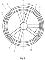
- Fig. 2 depicts the same steering wheel 10 with the display 12, where the both are turned clockwise with respect to reference line E and along a direction F with an angle J. It can be seen that the fitting points G are physically rotated as well. With the rotation of the steering wheel 10, the information contents C and D are still displayed and rendered centrically and respectively in the upper zone 121 and the bottom zone 122.
- Fig. 3 schematically depicts one exemplary embodiment of a system 20 configured to provide the display 12 for a steering wheel 10 as described above.
- the system 20 comprises an angle measurement unit 21, a rendering unit 22 and a display unit 23.
- the angle measurement unit 21 is configured to identify a rotation angle J of the steering wheel 10 and the display 12.
- the rendering unit 22 is configured to receive the measured angle J from the angle measurement unit 21 and information content to be displayed to render final images to the display unit 23, e.g., the display 12 as described above, at a right position.
- the angle measurement unit 21 can be optionally an inertial measurement unit (IMU) or an appropriate encoder unit in a steering column.
- IMU inertial measurement unit
- Fig. 4 shows an exemplary standard encoder for angle determination for a steering wheel.
- M 1 is the marking position of a marking point M before the steering wheel is turned.
- the marking point M is moved from M 1 to M 2 , and the corresponding angle J is thus measured.
- Fig. 5 shows an exemplary standard IMU acceleration measurement unit 21. Similar to the above described encoder, a position M 1 of a marking point M is recorded. Upon turning the steering wheel, the IMU unit measures the rotation angle J according to the first position M 1 and the second position M 2 of marking point M.
- Fig. 6 shows an example illustrating how the system 20 shown in Fig. 3 works. This example focuses on the upper zone 121 of the display 12. It should be understood by the skilled person in the art that the same technology and methods can be applied to the lower zone 122 of the display 12 as well.
- the rendering unit 22 of the system 20 comprises a calculation unit 221 and a display driver unit 222.
- the calculation unit 221 is configured to calculate absolute position where the information content is to be rendered.
- the display driver unit 222 is usually offered by a display vendor or a third party manufacturer that applies a rendered rectangular image to a specific and corresponding type of display.
- the display 12 comprises two 180° type displays each corresponding to the upper zone and the bottom zone 121, 122 as described in Figs. 1 and 2 . These two 180° type are separated with respect to and at the fitting points G.
- the display driver unit 222 maps x max of a rectangular image to N for the 180° display and x offset to 0 , where N is defined as the maximum size of the ring shaped 180° display (physical mapping of x max ) and O is defined as the offset in the ring shaped 180° display (physical mapping of x offset ) .
Abstract
A system (20) configured to display information content on a steering wheel and a display device (12) for a steering wheel (10) are described. The system comprises: an angle measurement unit (21) configured to identify a rotation angle of the steering wheel, a rendering unit (22) configured to receive the measured rotation angle and the information content to be displayed, and a display device (23). The display device has a shape of a ring and comprise an upper zone (121) and a bottom zone (122) for displaying information content. The displayed information content in the upper zone (121) and in the bottom zone (122) are both vertically aligned with respect to the display device.
Description
- The present disclosure relates to a display device for a steering wheel and a system configured to display information content on a steering wheel. Especially, the proposed display device can be applied in the field of automotive, game controller, etc.
- In the fields and applications of smart cars, new display technologies are investigated to get information to the eyes of the car driver without refracting drivers' focus from front window view too much. For example, there are prototypes and products of head-up displays (HUB). Besides, there are also wheel based solutions for such demands of new displays such as BMW M Performance Steering Wheel with digital display, FARRINGDON SWIS Steering Wheels, and AiM GT Steering Wheel, etc.
- However, there are some problems and disadvantages for the wheel based displays available nowadays. For example, when a driver turns the steering wheel, the display attach thereto and also the displayed text would be turned out of position or even out of the driver's sight as well. This can lead to distraction and confusion for the driver and thus reduce the safety.
- Therefore, it is an object to provide a solution for a display suitable to be used on a steering wheel in a vehicle such that information can be displayed stationary, even when the steering wheel is turned by the driver.
- According to one embodiment, a display device for a steering wheel is proposed. The display device has a shape of a ring and comprise upper zone and a bottom zone for displaying information content. The displayed information content in the upper zone and in the bottom zone are both vertically aligned with respect to the display device. Especially, the information content displayed in the upper zone and the information content displayed in the bottom zone are vertically flipped with respect to each other. When the display device is turned or rotated, the information content in the upper zone and bottom zone are still centrically displayed.
- In one embodiment, the display device is split up to an upper 180° display type and a lower 180° display type with respect to fitting points of the display device. if parts of the information content rendered to a 180° display type exceeds the fitting points of the display, the parts of the information content is rendered to the other 180° display type.
- According to one embodiment, a system configured to display information content on a steering wheel is introduced. The system comprises: an angle measurement unit (21) configured to identify a rotation angle of the steering wheel, a rendering unit (22) configured to receive the measured rotation angle and the information content to be displayed, and a display device.
- Same or similar advantages, which have been mentioned with respect to the display device according to the current principles, apply to the system in the same or similar way.
- Further characteristics of the present solution will become apparent from the description of the embodiments together with the claims and the included drawings. Embodiments can fulfill individual characteristics or a combination of several characteristics.
-
- Fig. 1
- depicts an embodiment of a display device for a steering wheel according to the present principles.
- Fig. 2
- depicts an exemplary situation when the display device shown in
Fig. 1 is turned according to the present principles. - Fig. 3
- schematically depicts one embodiment of a system to provide a display device for a steering wheel according to the present principles.
- Fig. 4
- shows an exemplary encoder used as an angle measurement unit in the system shown in
Fig. 3 according to the present principles. - Fig. 5
- shows an exemplary inertial measurement unit used as an angle measurement unit in the system shown in
Fig. 3 according to the present principles. - Fig. 6
- shows an exemplary embodiment illustrating how the system shown in
Fig. 3 works according to the present principles. - For a better understanding the proposed solutions shall now be explained in more detail in the following description with reference to the figures. It is understood that the solutions are not limited to the disclosed exemplary embodiments and that specified features can also expediently be combined and/or modified without departing from the scope of the proposed solutions as defined in the appended claims and exhibited in the figures.
- Referring to
Fig. 1 , an embodiment of adisplay device 12 for asteering wheel 10 is depicted at its default position. To be used with thesteering wheel 10, thedisplay device 12 has a shape of a ring. - The
display device 12 has anupper zone 121 and abottom zone 122. As shown in the embodiment inFig. 1 , theupper zone 121 is displayed with information content C, preferably the information connecting to the current driving situation, and the bottom zone is displayed with information content D, preferably information that is of less priority to the current driving situation. - It is also preferred that the information content C and D are rendered centrically with respect to the
upper zone 121 and thebottom zone 122. In this way, it is easier and more straight-forward for a driver to read and understand the information contents. - The information contents C and D can be text, characters, symbols, graphs, or any combination thereof. In addition, the information contents C and D are both displayed and aligned vertically with respect to a horizontal reference line E, which is preferably in line with the middle diameter of the ring of the display when the display is at its default position. In other words, the information contents C and D needs to be flipped vertically between the top and
bottom zones bottom zones -
Fig. 2 depicts thesame steering wheel 10 with thedisplay 12, where the both are turned clockwise with respect to reference line E and along a direction F with an angle J. It can be seen that the fitting points G are physically rotated as well. With the rotation of thesteering wheel 10, the information contents C and D are still displayed and rendered centrically and respectively in theupper zone 121 and thebottom zone 122. -
Fig. 3 schematically depicts one exemplary embodiment of asystem 20 configured to provide thedisplay 12 for asteering wheel 10 as described above. Thesystem 20 comprises anangle measurement unit 21, arendering unit 22 and adisplay unit 23. Theangle measurement unit 21 is configured to identify a rotation angle J of thesteering wheel 10 and thedisplay 12. Therendering unit 22 is configured to receive the measured angle J from theangle measurement unit 21 and information content to be displayed to render final images to thedisplay unit 23, e.g., thedisplay 12 as described above, at a right position. - The
angle measurement unit 21 can be optionally an inertial measurement unit (IMU) or an appropriate encoder unit in a steering column. -
Fig. 4 shows an exemplary standard encoder for angle determination for a steering wheel. M1 is the marking position of a marking point M before the steering wheel is turned. Upon a turning of the steering wheel, the marking point M is moved from M1 to M2, and the corresponding angle J is thus measured. -
Fig. 5 shows an exemplary standard IMUacceleration measurement unit 21. Similar to the above described encoder, a position M1 of a marking point M is recorded. Upon turning the steering wheel, the IMU unit measures the rotation angle J according to the first position M1 and the second position M2 of marking point M. -
Fig. 6 shows an example illustrating how thesystem 20 shown inFig. 3 works. This example focuses on theupper zone 121 of thedisplay 12. It should be understood by the skilled person in the art that the same technology and methods can be applied to thelower zone 122 of thedisplay 12 as well. - Preferably, the
rendering unit 22 of thesystem 20 comprises acalculation unit 221 and adisplay driver unit 222. Thecalculation unit 221 is configured to calculate absolute position where the information content is to be rendered. Thedisplay driver unit 222 is usually offered by a display vendor or a third party manufacturer that applies a rendered rectangular image to a specific and corresponding type of display. In this embodiment, thedisplay 12 comprises two 180° type displays each corresponding to the upper zone and thebottom zone Figs. 1 and2 . These two 180° type are separated with respect to and at the fitting points G. - For the
calculation unit 221 to calculate the absolute position, it is assumed that the maximum possible image resolution xmax for the horizontal direction and ymax for the vertical direction of the display are known. Inputs to thecalculation unit 221 are the rotation angle of the steering wheel J and the information content to be displayed. For example, as shown inFig. 6 , the information content to be rendered is "Text and characters to display". Thecalculation unit 221 analyze the x-resolution of the text to be rendered as xtextsize. In order to render the text in the middle of the display, the offset xoffset needs to be calculated as well depending on xmax and xtextsize.
- In order to render every horizontal position x of a text, the text needs to be mapped on real horizontal display coordinates x':

- In case x' becomes negative, the corresponding part of the text needs to be rendered to the other part of the display, i.e. the bottom 180° type of display.
- The shift with respect to the reference line E and the physical fitting points G are as following:

- In the exemplary embodiment of
Fig. 6 , thedisplay driver unit 222 maps xmax of a rectangular image to N for the 180° display and xoffset to 0, where N is defined as the maximum size of the ring shaped 180° display (physical mapping of xmax ) and O is defined as the offset in the ring shaped 180° display (physical mapping of xoffset ). - The foregoing illustrates the principles of the disclosure and it will thus be appreciated that those skilled in the art will be able to devise numerous alternative arrangements which, although not explicitly described herein, embody the principles and are within its scope. It is therefore to be understood that numerous modifications can be made to the illustrative embodiments and that other arrangements can be devised without departing from the scope of the present principle as defined by the appended claims.
Claims (7)
- A display device (12) for a steering wheel (10), the display device (12) having a shape of a ring and comprising an upper zone (121) and a bottom zone (122) for displaying information content, wherein the displayed information content in the upper zone (121) and in the bottom zone (122) are both vertically aligned with respect to the display device (12).
- The display device (12) of claim 1, wherein the information content displayed in the upper zone (121) and the information content displayed in the bottom zone (122) are vertically flipped with respect to each other.
- The display device (12) of claim 1 or 2, wherein, when the display device is turned or rotated, the information content in the upper zone and bottom zone are still centrically displayed.
- The display device (12) of one of the preceding claims, wherein the display device (12) is split up to an upper 180° display type and a lower 180° display type with respect to fitting points (G) of the display device.
- The display device (12) of claim 4, where if parts of the information content rendered to a 180° display type exceeds the fitting points of the display, the parts of the information content is rendered to the other 180° display type.
- A system (20) configured to display information content on a steering wheel (10), the system comprising:- an angle measurement unit (21) configured to identify a rotation angle of the steering wheel,- a rendering unit (22) configured to receive the measured rotation angle and the information content to be displayed, and- a display device as claimed in one of the preceding claims.
- The system of claim 6, where in the angle measurement unit (21) is an inertial measurement unit or an encoder unit in a steering column.
Priority Applications (1)
| Application Number | Priority Date | Filing Date | Title |
|---|---|---|---|
| EP16305156.8A EP3205557A1 (en) | 2016-02-11 | 2016-02-11 | A display device for a steering wheel and a system to display information content on a steering wheel |
Applications Claiming Priority (1)
| Application Number | Priority Date | Filing Date | Title |
|---|---|---|---|
| EP16305156.8A EP3205557A1 (en) | 2016-02-11 | 2016-02-11 | A display device for a steering wheel and a system to display information content on a steering wheel |
Publications (1)
| Publication Number | Publication Date |
|---|---|
| EP3205557A1 true EP3205557A1 (en) | 2017-08-16 |
Family
ID=55398241
Family Applications (1)
| Application Number | Title | Priority Date | Filing Date |
|---|---|---|---|
| EP16305156.8A Withdrawn EP3205557A1 (en) | 2016-02-11 | 2016-02-11 | A display device for a steering wheel and a system to display information content on a steering wheel |
Country Status (1)
| Country | Link |
|---|---|
| EP (1) | EP3205557A1 (en) |
Cited By (4)
| Publication number | Priority date | Publication date | Assignee | Title |
|---|---|---|---|---|
| US20160159386A1 (en) * | 2013-07-08 | 2016-06-09 | R&Ders Co.,Ltd. | Steering wheel having display device |
| DE102019211657A1 (en) * | 2019-08-02 | 2021-02-04 | Audi Ag | Device for displaying display content for a motor vehicle and a method, a motor vehicle and a steering unit for this purpose |
| CN112874620A (en) * | 2019-11-29 | 2021-06-01 | 比亚迪股份有限公司 | Steering wheel device and automobile |
| CN114408013A (en) * | 2021-12-27 | 2022-04-29 | 北京车和家汽车科技有限公司 | Display control method, device, medium, and apparatus for function icons on steering wheel |
Citations (5)
| Publication number | Priority date | Publication date | Assignee | Title |
|---|---|---|---|---|
| US5666102A (en) * | 1996-07-24 | 1997-09-09 | United Technologies Automotive Systems, Inc. | Vehicle signals incorporated into steering wheel rim |
| DE10346691A1 (en) * | 2003-10-08 | 2005-05-12 | Volkswagen Ag | Driver assistance system has a steering wheel mounted display device for information output that is configured so that an indicated direction is perceived by the driver in a manner independent of the steering wheel position |
| US20080143505A1 (en) * | 2006-12-15 | 2008-06-19 | Shuji Maruyama | Display system and method for steering wheel of vehicle |
| WO2015005587A1 (en) * | 2013-07-08 | 2015-01-15 | 알앤더스 주식회사 | Steering wheel having display device |
| CN204172972U (en) * | 2014-05-12 | 2015-02-25 | 北京汽车股份有限公司 | Car status information read out instrument on a kind of bearing circle |
-
2016
- 2016-02-11 EP EP16305156.8A patent/EP3205557A1/en not_active Withdrawn
Patent Citations (5)
| Publication number | Priority date | Publication date | Assignee | Title |
|---|---|---|---|---|
| US5666102A (en) * | 1996-07-24 | 1997-09-09 | United Technologies Automotive Systems, Inc. | Vehicle signals incorporated into steering wheel rim |
| DE10346691A1 (en) * | 2003-10-08 | 2005-05-12 | Volkswagen Ag | Driver assistance system has a steering wheel mounted display device for information output that is configured so that an indicated direction is perceived by the driver in a manner independent of the steering wheel position |
| US20080143505A1 (en) * | 2006-12-15 | 2008-06-19 | Shuji Maruyama | Display system and method for steering wheel of vehicle |
| WO2015005587A1 (en) * | 2013-07-08 | 2015-01-15 | 알앤더스 주식회사 | Steering wheel having display device |
| CN204172972U (en) * | 2014-05-12 | 2015-02-25 | 北京汽车股份有限公司 | Car status information read out instrument on a kind of bearing circle |
Cited By (4)
| Publication number | Priority date | Publication date | Assignee | Title |
|---|---|---|---|---|
| US20160159386A1 (en) * | 2013-07-08 | 2016-06-09 | R&Ders Co.,Ltd. | Steering wheel having display device |
| DE102019211657A1 (en) * | 2019-08-02 | 2021-02-04 | Audi Ag | Device for displaying display content for a motor vehicle and a method, a motor vehicle and a steering unit for this purpose |
| CN112874620A (en) * | 2019-11-29 | 2021-06-01 | 比亚迪股份有限公司 | Steering wheel device and automobile |
| CN114408013A (en) * | 2021-12-27 | 2022-04-29 | 北京车和家汽车科技有限公司 | Display control method, device, medium, and apparatus for function icons on steering wheel |
Similar Documents
| Publication | Publication Date | Title |
|---|---|---|
| RU2675944C1 (en) | Vehicle displaying device and method | |
| EP3205557A1 (en) | A display device for a steering wheel and a system to display information content on a steering wheel | |
| CN108136906B (en) | Display apparatus and vehicle display methods | |
| US9690104B2 (en) | Augmented reality HUD display method and device for vehicle | |
| US8884789B2 (en) | Method and device for displaying information in a vehicle | |
| US20120235805A1 (en) | Information display apparatus and information display method | |
| WO2015159500A1 (en) | Head-up display device | |
| WO2017022047A1 (en) | Display control device, display device, and display control method | |
| US9873378B2 (en) | Vehicle, display system and method for displaying a piece of traffic-relevant information | |
| Pfannmüller et al. | A comparison of display concepts for a navigation system in an automotive contact analog head-up display | |
| US20180031849A1 (en) | Augmented reality head-up display road correction | |
| US20200174916A1 (en) | Human Machine Blur Testing Method | |
| CN109788243B (en) | System unreliability in identifying and visually presenting display enhanced image content | |
| US20220227384A1 (en) | Method for Carrying out a Correction of the Direction of Travel by a Driver Assistance System in a Motor Vehicle, and a Control Device Therefor | |
| EP2610589A1 (en) | Method of displaying points of interest | |
| US9452676B2 (en) | On-board display control device and on-board display control method | |
| US20210049985A1 (en) | Image control apparatus, display apparatus, mobile body, image data generation method, and recording medium | |
| JP5136773B2 (en) | Vehicle display device | |
| JP6385138B2 (en) | In-vehicle display control device and in-vehicle display control method | |
| JP6482431B2 (en) | Display control device, display device, and display control method | |
| Creaser et al. | Evaluation of driver performance and distraction during use of in-vehicle signing information | |
| US20160275715A1 (en) | Map image display device, navigation device, and map image display method | |
| WO2017042923A1 (en) | Display control device, display device, and display control method | |
| JP2016168927A (en) | Information display system | |
| JP6282567B2 (en) | Vehicle display device |
Legal Events
| Date | Code | Title | Description |
|---|---|---|---|
| PUAI | Public reference made under article 153(3) epc to a published international application that has entered the european phase |
Free format text: ORIGINAL CODE: 0009012 |
|
| AK | Designated contracting states |
Kind code of ref document: A1 Designated state(s): AL AT BE BG CH CY CZ DE DK EE ES FI FR GB GR HR HU IE IS IT LI LT LU LV MC MK MT NL NO PL PT RO RS SE SI SK SM TR |
|
| AX | Request for extension of the european patent |
Extension state: BA ME |
|
| STAA | Information on the status of an ep patent application or granted ep patent |
Free format text: STATUS: THE APPLICATION IS DEEMED TO BE WITHDRAWN |
|
| 18D | Application deemed to be withdrawn |
Effective date: 20180217 |