EP3181306A1 - Battery operated machine tool iii - Google Patents
Battery operated machine tool iii Download PDFInfo
- Publication number
- EP3181306A1 EP3181306A1 EP15200669.8A EP15200669A EP3181306A1 EP 3181306 A1 EP3181306 A1 EP 3181306A1 EP 15200669 A EP15200669 A EP 15200669A EP 3181306 A1 EP3181306 A1 EP 3181306A1
- Authority
- EP
- European Patent Office
- Prior art keywords
- tool
- rear handle
- hand tool
- plane
- handle
- Prior art date
- Legal status (The legal status is an assumption and is not a legal conclusion. Google has not performed a legal analysis and makes no representation as to the accuracy of the status listed.)
- Withdrawn
Links
- 230000000087 stabilizing effect Effects 0.000 claims description 13
- 241000271460 Crotalus cerastes Species 0.000 description 1
- 230000005484 gravity Effects 0.000 description 1
- 238000003780 insertion Methods 0.000 description 1
- 230000037431 insertion Effects 0.000 description 1
- 230000003287 optical effect Effects 0.000 description 1
Images


Classifications
-
- B—PERFORMING OPERATIONS; TRANSPORTING
- B25—HAND TOOLS; PORTABLE POWER-DRIVEN TOOLS; MANIPULATORS
- B25F—COMBINATION OR MULTI-PURPOSE TOOLS NOT OTHERWISE PROVIDED FOR; DETAILS OR COMPONENTS OF PORTABLE POWER-DRIVEN TOOLS NOT PARTICULARLY RELATED TO THE OPERATIONS PERFORMED AND NOT OTHERWISE PROVIDED FOR
- B25F5/00—Details or components of portable power-driven tools not particularly related to the operations performed and not otherwise provided for
- B25F5/02—Construction of casings, bodies or handles
- B25F5/021—Construction of casings, bodies or handles with guiding devices
- B25F5/023—Construction of casings, bodies or handles with guiding devices with removably attached levels
-
- B—PERFORMING OPERATIONS; TRANSPORTING
- B23—MACHINE TOOLS; METAL-WORKING NOT OTHERWISE PROVIDED FOR
- B23D—PLANING; SLOTTING; SHEARING; BROACHING; SAWING; FILING; SCRAPING; LIKE OPERATIONS FOR WORKING METAL BY REMOVING MATERIAL, NOT OTHERWISE PROVIDED FOR
- B23D45/00—Sawing machines or sawing devices with circular saw blades or with friction saw discs
- B23D45/16—Hand-held sawing devices with circular saw blades
-
- B—PERFORMING OPERATIONS; TRANSPORTING
- B23—MACHINE TOOLS; METAL-WORKING NOT OTHERWISE PROVIDED FOR
- B23D—PLANING; SLOTTING; SHEARING; BROACHING; SAWING; FILING; SCRAPING; LIKE OPERATIONS FOR WORKING METAL BY REMOVING MATERIAL, NOT OTHERWISE PROVIDED FOR
- B23D47/00—Sawing machines or sawing devices working with circular saw blades, characterised only by constructional features of particular parts
- B23D47/02—Sawing machines or sawing devices working with circular saw blades, characterised only by constructional features of particular parts of frames; of guiding arrangements for work-table or saw-carrier
-
- B—PERFORMING OPERATIONS; TRANSPORTING
- B23—MACHINE TOOLS; METAL-WORKING NOT OTHERWISE PROVIDED FOR
- B23D—PLANING; SLOTTING; SHEARING; BROACHING; SAWING; FILING; SCRAPING; LIKE OPERATIONS FOR WORKING METAL BY REMOVING MATERIAL, NOT OTHERWISE PROVIDED FOR
- B23D51/00—Sawing machines or sawing devices working with straight blades, characterised only by constructional features of particular parts; Carrying or attaching means for tools, covered by this subclass, which are connected to a carrier at both ends
- B23D51/01—Sawing machines or sawing devices working with straight blades, characterised only by constructional features of particular parts; Carrying or attaching means for tools, covered by this subclass, which are connected to a carrier at both ends characterised by the handle
-
- B—PERFORMING OPERATIONS; TRANSPORTING
- B25—HAND TOOLS; PORTABLE POWER-DRIVEN TOOLS; MANIPULATORS
- B25F—COMBINATION OR MULTI-PURPOSE TOOLS NOT OTHERWISE PROVIDED FOR; DETAILS OR COMPONENTS OF PORTABLE POWER-DRIVEN TOOLS NOT PARTICULARLY RELATED TO THE OPERATIONS PERFORMED AND NOT OTHERWISE PROVIDED FOR
- B25F5/00—Details or components of portable power-driven tools not particularly related to the operations performed and not otherwise provided for
- B25F5/02—Construction of casings, bodies or handles
-
- B—PERFORMING OPERATIONS; TRANSPORTING
- B27—WORKING OR PRESERVING WOOD OR SIMILAR MATERIAL; NAILING OR STAPLING MACHINES IN GENERAL
- B27B—SAWS FOR WOOD OR SIMILAR MATERIAL; COMPONENTS OR ACCESSORIES THEREFOR
- B27B17/00—Chain saws; Equipment therefor
- B27B17/0008—Means for carrying the chain saw, e.g. handles
-
- B—PERFORMING OPERATIONS; TRANSPORTING
- B27—WORKING OR PRESERVING WOOD OR SIMILAR MATERIAL; NAILING OR STAPLING MACHINES IN GENERAL
- B27B—SAWS FOR WOOD OR SIMILAR MATERIAL; COMPONENTS OR ACCESSORIES THEREFOR
- B27B9/00—Portable power-driven circular saws for manual operation
-
- B—PERFORMING OPERATIONS; TRANSPORTING
- B27—WORKING OR PRESERVING WOOD OR SIMILAR MATERIAL; NAILING OR STAPLING MACHINES IN GENERAL
- B27B—SAWS FOR WOOD OR SIMILAR MATERIAL; COMPONENTS OR ACCESSORIES THEREFOR
- B27B9/00—Portable power-driven circular saws for manual operation
- B27B9/02—Arrangements for adjusting the cutting depth or the amount of tilting
-
- H—ELECTRICITY
- H01—ELECTRIC ELEMENTS
- H01H—ELECTRIC SWITCHES; RELAYS; SELECTORS; EMERGENCY PROTECTIVE DEVICES
- H01H9/00—Details of switching devices, not covered by groups H01H1/00 - H01H7/00
- H01H9/02—Bases, casings, or covers
- H01H9/06—Casing of switch constituted by a handle serving a purpose other than the actuation of the switch, e.g. by the handle of a vacuum cleaner
- H01H2009/065—Battery operated hand tools in which the battery and the switch are directly connected
Definitions
- the present invention relates to a battery-operated hand tool, in particular a circular saw, with an electric motor for rotationally driving a to be arranged on the power tool, in particular a saw blade.
- the hand tool has, in each case based on a feed direction of the power tool, a front and rear handle. Furthermore, the hand tool has a receiving bay for receiving a removable battery. The removable battery is used to supply the electric motor.
- Such hand tool machines are basically known from the prior art. Also known from the prior art are hand tool machines whose electric motor is formed via a worm gear of the power tool a tool, e.g. in the form of a saw blade, to power.
- worm-drive saw WDS
- the worm gear allows a right-angled arrangement of the motor shaft (worm shaft) and the tool axis, i. Saw blade axis (output axis for the saw blade).
- worm-drive saw worm-drive saw
- the worm gear allows a right-angled arrangement of the motor shaft (worm shaft) and the tool axis, i. Saw blade axis (output axis for the saw blade).
- worm shaft motor shaft
- Saw blade axis output axis for the saw blade
- circular saws designed as WDS have an elongate, less broad shape than "side winder” (SW) preferred in Europe, in which the motor axis and saw blade axis are arranged coaxially, but at least parallel to one
- the rear handle is mounted laterally pivotable about a pivot axis, such that when the rear handle is in a swung-out state, the receiving bay for receiving or removing the removable battery is released, and if the rear Handle is located in a pivoted state, the up or removal of the removable battery is locked in or out of the receiving bay.
- the battery-powered hand tool according to the invention allows a particularly easy insertion or removal of a removable battery.
- the portable circular saw according to the invention has improved handling compared to known from the prior art battery-powered portable power tools, especially circular saws, on.
- the invention further includes the recognition that the elongated, less broad shape of the prior art circular saws of the prior art designed as WDS requires top-heavy ergonomics, which are preferred for so-called "drop cuts", ie cuts in the vertical direction from top to bottom , Due to the fact that the receiving bay for receiving the removable battery can be released by pivoting the rear handle, the preferred ergonomics of a portable circular saw designed as a WDS are at least favored in addition to the already mentioned advantageously simple battery change.
- a length of the power tool along the feed direction is at least twice as large as a width of the power tool transverse to the feed direction.
- Feed direction is to be understood in the context of the present invention, a thrust direction when working properly with the power tool, ie in particular not a possibly temporarily assumed thrust direction for releasing a jammed tool, in particular a saw blade, from a saw.
- the pivot axis is oriented in the feed direction of the circular saw.
- the pivot axis has a pivot point on which lies above, preferably exclusively above, a ground plane and / or below, preferably exclusively below, a parallel plane parallel to this ground plane.
- the ground plane can be spanned by a underside of a base plate of the handheld power tool that is in a zero-degree position and / or has been set to a maximum depth of cut.
- the bottom plate is located in zero-degree position when the underside of the bottom plate contacting a workpiece in working mode is perpendicular to the flat saw blade.
- the plane parallel to the ground plane parallel plane preferably has a distance from the ground plane.
- the axis of rotation of the tool is preferably in the parallel plane.
- the pivot point is preferably arranged below the receiving bay and particularly preferably formed in a stabilizing rail of the power tool. In other words, in this preferred embodiment, the rear handle "down" struck on the circular saw.
- the pivot point is preferably located exclusively in a room side facing the rear handle side of an axial plane, wherein the axial plane is spanned by the axis of rotation and a radius of the tool.
- the axial plane preferably encloses an angle of 90 degrees, starting from a section of a ground plane located in front of the axis of rotation in the feed direction and in the direction of rotation of the tool.
- the pivot point preferably exclusively, lies in a space side of a distance plane ABE facing the front handle.
- the distance plane is parallel to the axial plane and / or has to the axial plane at a distance which is at least as large and / or at most twice as large as a maximum possible tool diameter of a respective hand tool.
- the pivot point may, preferably exclusively, lie in a space side of a handle plane facing the front handle.
- the handle plane is clamped by the axis of rotation and a radius of the tool, wherein the handle plane, starting from a lying in the feed direction behind the rotation axis portion of a ground plane and in the opposite direction of rotation of the tool, an angle of at least 20 degrees and preferably at least 30 degrees.
- the pivot point is preferably arranged above the receiving bay and particularly preferably formed in a rail of the power tool. In other words, in this preferred embodiment, the rear handle "top" posted on the power tool.
- the currently defined positional conditions of the pivot axis can apply both individually and in combination.
- the ground plane the axial plane, the distance plane and the parallel plane, a space area in the form of a cuboid, in which the pivot point is arranged or to be arranged.
- the pivot point is in a stabilizing rail of the power tool.
- the center of gravity may lie in a profile rail of the power tool.
- the pivot axis may extend through a cylindrical pin which is mounted in pin holder.
- the hand tool machine has a latching mechanism which is designed to securely hold the rear handle in the swung-out state, preferably until overcoming a spring-locking force by the user.
- the spring-locking force can be formed for example by a pressure piece with ball and spring and at least one corresponding detent recess.
- a mechanism is formed near the pivot axis, which allows a particularly compact structure.
- the latching mechanism may alternatively be formed by a magnetic pairing, preferably in the region of the pivot stop and / or the counter-stop. It is also possible to realize the locking mechanism by means of loop spring friction.
- Each of these options is configured such that the rear handle is held securely in the pivoted-out state until a force applied by the user to the rear handle overcomes the spring-locking force of the detent mechanism.
- the rear handle on a locking mechanism which is adapted to fix the rear handle in its pivoted state and / or release, if necessary, for a pivoting movement. It has proven to be advantageous if below the receiving bay a stabilizing rail is arranged, which preferably projects against the feed direction beyond the receiving bay out and on which the rear handle can be preferably fixed in its pivoted state.
- a fixation of the rear handle in its pivoted state on the stabilizing rail allows a high stability of the rear handle and thus an optimal power flow in the feed direction of the power tool.
- the locking mechanism comprises a pin which can engage in a recess provided for this, which is preferably formed on the stabilizing rail or rail.
- the locking mechanism may also be configured by a hook with a corresponding eyelet. This is preferably when the rear handle is in the pivoted state. About such a locking mechanism, the rear handle is locked so that a particularly safe operation of the power tool is achieved by avoiding unwanted pivoting of the rear handle.
- the locking mechanism may be configured to assist in swung automatically locked state. Alternatively, the locking mechanism may be configured to be locked by operation of an operating member by the user.
- the safety of the portable circular saw is increased by having a safety switch which is connected to the rear handle and is designed to interrupt a power supply to the electric motor in the unlocked state of the locking mechanism and / or in the presence of the swung-out state.
- the safety switch can immediately interrupt the main power supply of the power tool or an electronics transmit the state of the locking mechanism and prohibit a start in the electronic logic of a start of the power tool, in particular a saw, despite pressing the on / off switch.
- the safety switch can be electrical, magnetic and / or optical. Several ways of arranging the safety switch are conceivable.
- the safety switch may for example be part of the mechanical switching element or be mechanically connected thereto.
- the safety switch can be arranged in the region of the pivot axis or the pivot point of the rear handle.
- the receiving bay on a rail guide over which the removable battery can be inserted into the receiving bay and pulled out of this.
- the rail guide and / or the removable battery is designed such that a withdrawal of the removable battery is possible only after actuation of a release element.
- the release element is designed as a button and arranged on the removable battery.
- a hand engagement surface of the rear handle based on the feed direction of the power tool, is added behind the recorded in the receiving bay removable battery.
- the tool based on the feed direction of the power tool, is arranged to the left or right of the electric motor.
- the output shaft of the electric motor may be parallel to the axis of rotation of the saw blade.
- the circular saw is preferably at least twice as long as it is wide.
- the circular saw is free of a worm gear.
- battery-powered portable circular saw configured hand tool reach the ergonomics of a provided as WDS and designed in the form of a circular saw handheld power tool.
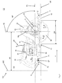
- FIG. 1 A preferred embodiment of a designed as a battery-powered portable circular saw hand tool 100 is in Fig. 1 shown.
- the battery-powered circular saw 100 has an electric motor 60 for rotatably driving a tool 90 arranged on the circular saw 100 as a saw blade.
- the saw blade 90 is rotationally driven about a rotation axis R, which in the present case points into the plane of the drawing.
- the saw blade 90 rotates in the direction of rotation D.
- the saw blade 90 rotates in such a way that the circular saw 100 is used in the sawing operation on a workpiece to be sawn (not shown).
- the circular saw 100 is advanced in the feed direction V.
- the feed direction is in Fig. 1 with a horizontal arrow pointing to the right.
- the circular saw 100 has a front handle 20 and a rear handle 30. Relative to the feed direction V of the portable circular saw 100, the front handle 20 is arranged in front of the rear handle 30.
- the portable circular saw 100 has a receiving bay 50 for receiving a replaceable battery 200.
- the removable battery 200 is completely accommodated in the receiving bay 50 for operating the electric motor 60 of the hand-held power tool 100 designed as a portable circular saw.
- the rear handle 30 is pivotably mounted about a pivot axis S.
- the rear handle 30 is pivotally mounted about the pivot axis S, that when the rear handle 30 in a swung-out state (see. Fig. 3 ) is located, the receiving bay 50 is released for attaching or removing the removable battery 200.
- the rear handle 30 is pivotally mounted about the pivot axis S, that when the rear handle 30 in the pivoted state EZ (see. Fig. 1 and 2 ) is located, the up or removal of the removable battery 200 is locked in or out of the receiving bay 50.
- the rear handle 30 is pivotally mounted laterally downwards, ie the rear handle 30 pivots about an imaginary arc B (in Fig. 2 indicated by an arrow) whose center of curvature lies on the pivot axis S.
- the pivot axis S in the feed direction V of the circular saw 100 is oriented.
- the pivot axis S is not necessarily parallel to the feed direction V, but can - as out Fig. 1 it can be seen - slightly oblique to the feed direction V, for example, with a maximum inclination angle of 20 degrees.
- the pivot axis S extends exclusively above a ground plane GE.
- the ground plane GE can also be designed as a base plate plane.
- the ground plane GE corresponds to the base plate plane.
- designed as a portable circular hand tool 100 has a bottom plate 10.
- the bottom plate can also be referred to as a base plate. This is the case in particular if the handheld power tool contains a baseplate. However, it is also possible for the handheld power tool 100 not to include a base plate 10 or base plate.
- a designed as a floor level ground plane GE is clamped by a working in the operation of a workpiece contacting bottom 11 of a zero-degree position and set up for maximum depth of cut bottom plate 10 of the portable circular saw 100.
- the spanned by bottom 11 of the bottom plate 10 floor level GE is also in the perspective view of Fig. 2 clarified.
- Fig. 1 is shown parallel to the ground plane GE parallel plane PE.
- the pointing in the plane of rotation R of the saw blade configured as tool 90 is in this parallel plane PE.
- the pivot point SP lies exclusively below this parallel plane.
- the rear handle 30 is struck "under”.
- Fig. 1 shown is an axial plane AE, which is spanned by the rotation axis R and by a radius RA of the saw blade 90.
- the axial plane AE closes, starting from a lying in the feed direction V in front of the axis of rotation R section 12 of the bottom plate 10 and in the direction of rotation D of the saw blade 90 at an angle exactly 90 degrees.
- Fig. 1 Also in Fig. 1 is shown that the pivot point SP is located exclusively in a front handle 20 facing space side of a distance plane ABE.
- the distance plane ABE is parallel to the axial plane AE and has a distance AS to this axial plane AE, which in the presently illustrated exemplary embodiment is approximately twice as large as the maximum possible saw blade diameter DB of the portable circular saw 100.
- the ground plane GE, the axial plane AE, the distance plane ABE and the parallel plane PE include a spatial region in the form of a cuboid, in which the pivot point SP is arranged.
- the pivot axis S extends through a stabilizing rail 59 of the circular saw 100 and is located, relative to the vertical, below the receiving bay 50.
- both the bottom plate 10th stored as well as the electric motor 60 and its housing attached.
- the pivot point SP is spaced from the handle support 25 of the front handle 20th
- the rear handle 30 is pivotally supported by a cylindrical pin 70, which is coaxial with the pivot axis S, in a pin receptacle 71 of a stabilizing rail 59 of the portable circular saw 100.
- the rear handle 30 has a bore, not shown here, through which the cylinder pin 70 extends.
- Fig. 2 shows the rear handle 30 in the pivoted state EZ, so that the removal or removal of the removable battery 200 is locked in or out of the receiving bay 50.
- Fig. 2 shows now, based on the feed direction V, a back view of the designed as a portable circular hand tool 100 from Fig. 1 , The representation of the Fig. 2 It can be seen that the saw blade 90 is arranged to the left of the electric motor 60. Alternatively, the saw blade 90 can also be arranged to the right of the electric motor 60.
- Fig. 2 can also be taken well, is the pivot point SP between ground plane GE and parallel plane PE.
- the rotation axis R is again in the parallel plane PE.
- Fig. 2 a swing angle SW, which is defined between einwenktem state EZ and swung-out state AZ of the rear handle 30, will be explained in more detail.
- Fig. 2 indicated is a pivot stop 34 and a counter-stop 36 in the region of the pin receptacle 71 (see also Fig. 1 ), which limit the swivel angle SW.
- the rear handle 30 is in the pivoted state EZ, for example, the Fig. 1 and 2 can be removed.
- swivel angle SW between the pivoted state EZ and swung out AZ of the rear handle 30 exactly 90 degrees.
- the swivel angle SW is in this case based on the axis of rotation R.
- Fig. 3 shows the embodiment of the Fig. 1 and 2 , where in Fig. 3 the rear handle 30 is shown in its swung-out state AZ. In the pivoted-out state AZ, the receiving bay 50 is released for attaching or removing the replaceable battery 200. In Fig. 3 the removable battery 200 is included in the receiving bay.
- the fully swung out state AZ shown with a swivel angle SW of 90 degrees.
- a locking mechanism 40 On a rail 15 of the circular saw 100, a locking mechanism 40 is formed, with which the rear handle 30 can fix in its pivoted state EZ and, if necessary, can be released for a pivoting movement.
- the locking mechanism 40 has a mechanical switching element 46, by means of which a pin 45 attached to the rear handle (cf. Fig. 9 ) which can engage in a corresponding recess 48, can be locked.
- Fig. 4 can be removed, the recess 48 is formed for the mechanical switching element 45 on a rail 15, above the receiving bay 50 is arranged.
- the switching element 45 is received in the recess 48, which in Fig. 1 is shown.
- a safety switch 65 the in Fig. 4 illustrated embodiment is disposed within the recess 48 and can be actuated by the pin 45.
- the safety switch 65 is designed to interrupt a power supply to the electric motor 60 in the unlocked state of the locking mechanism 40 and in the presence of the swung-out state AZ. If the locking mechanism 40 is locked or the rear handle 30 is pivoted in, as shown in FIG Fig. 1 the case is, the safety switch 65 signals that the electric motor 60 may be actuated.
- the portable circular saw 100 has a rail 15. This rail 15 is formed, the rear handle 30, a contact surface in which the recess 48 is formed to offer. If the rear handle 30 is in the pivoted-in state EZ, located (cf. Fig. 1 ), the rear handle 30 is secured by the pin 45 against undesirable rotation transverse to the pivot axis S.
- a rail guide 55 is formed, via which the Kirakku 200 can be inserted into the receiving bay 50 and pulled out of this.
- the rail guide 55 is designed such that a withdrawal of the removable battery 200 is possible only after actuation of a release element 58 on the removable battery 200.
- motor shaft 61 of the electric motor 60 is parallel to the axis of rotation R of the saw blade 60.
- motor shaft 61 and axis of rotation 60 can extend coaxially in all embodiments.
- a parallel offset course of 61 and rotation axis 60 is (as shown) conceivable, for example, if a gear between the motor shaft 61 and saw blade 90 is provided.
- a maximum length L of the portable power tool 100 designed as a portable circular saw, relative to the feed direction V, is at least twice as long as a maximum width B of the portable power tool 100 designed as a portable circular saw, perpendicular to the feed direction V.
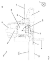
- FIG Fig. 5 A second preferred embodiment of a battery-powered portable circular saw 100 is shown in FIG Fig. 5 shown.
- the battery-powered circular saw 100 has an electric motor 60 for rotatably driving a saw blade 90 arranged on the portable circular saw 100.
- the saw blade 90 is rotationally driven about a rotation axis R, which in the present case points into the plane of the drawing.
- the saw blade 90 rotates in the direction of rotation D.
- the saw blade 90 rotates in such a way that the circular saw 100 is used in the sawing operation on a workpiece to be sawn (not shown).
- the circular saw 100 is advanced in the feed direction V.
- the feed direction is in Fig. 5 with a horizontal arrow pointing to the right.
- the circular saw 100 has a front handle 20 and a rear handle 30. Relative to the feed direction V of the portable circular saw 100, the front handle 20 is arranged in front of the rear handle 30.
- the portable circular saw 100 has a receiving bay 50 for receiving a replaceable battery 200.
- the removable battery 200 for operating the electric motor 60 of the portable circular saw 100 is completely received in the receiving bay 50.
- the rear handle 30 is pivotably mounted about a pivot axis S.
- the rear handle 30 is pivotally mounted about the pivot axis S, that when the rear handle 30 in a swung-out state (see. Fig. 7 ) is located, the receiving bay 50 is released for attaching or removing the removable battery 200.
- the rear handle 30 is pivotally mounted about the pivot axis S, that when the rear handle 30 in the pivoted state EZ (see. Fig. 5 and 6 ) is located, the up or removal of the removable battery 200 is locked in or out of the receiving bay 50.
- the rear handle 30 is pivotally mounted laterally upward, ie the rear handle 30 pivots about an imaginary arc (in Fig. 2 indicated by an arrow) whose center of curvature lies on the pivot axis S.
- the pivot axis S in the feed direction V of the circular saw 100 is oriented.
- the pivot axis S is not necessarily parallel to the feed direction V, but can - as out Fig. 5 is apparent - slightly oblique to the feed direction V extend, for example, with a maximum inclination angle of 340 degrees (in the counterclockwise direction).
- the pivot axis S has a pivot point SP, which lies exclusively above a ground plane GE.
- the ground plane GE is clamped by a base 11 of a zero-degree position which is in contact with a workpiece during operation and is set to the maximum depth of cut.
- the plane defined by bottom 11 of the bottom plate 10 floor level GE is also in the back side of the Fig. 6 clarified.
- FIG. 5 shown is an axial plane AE, which is spanned by the rotation axis R and by a radius RA of the saw blade 90.
- the axial plane AE closes, starting from a lying in the feed direction V in front of the axis of rotation R section 12 of the bottom plate 10 and in the direction of rotation D of the saw blade 90 at an angle exactly 90 degrees.
- Fig. 5 Also in Fig. 5 is shown that the pivot point SP is located exclusively in a front handle 20 facing space side of a distance plane ABE.
- the distance plane ABE is parallel to the axial plane AE and has a distance AS to this axial plane AE, which in the presently illustrated exemplary embodiment is approximately twice as large as the maximum possible saw blade diameter DB of the portable circular saw 100.
- a handle plane HE which is spanned by the rotation axis R and a radius RA 'of the saw blade 90.
- the handle plane HE includes, starting from a located in the feed direction V behind the rotation axis R section 13 of the bottom plate 10 and in the opposite direction of rotation D of the saw blade 90 by way of example an angle of 30 degrees.
- the pivot point SP lies exclusively in a front handle 20 facing the room side of the handle level HE. Thus, the rear handle 30 is struck "up”.
- the pivot axis S extends through a rail 15 of the circular saw 100.
- the pivot point 15 is based on the vertical, above the receiving bay 50th
- the handle plane HE, the axis plane AE, the distance plane EBA and the ground plane define in the presently illustrated embodiment, a truncated-wedge-shaped space area which is free of the pivot point 15.
- Fig. 6 shows now, based on the feed direction V, a back view of the circular saw 100 from Fig. 5 , The representation of the Fig. 6 It can be seen that the saw blade 90 is arranged to the left of the electric motor 60. Alternatively, the tool 90 designed as a saw blade, relative to the feed direction V of the hand tool 100, can also be arranged to the right of the electric motor 60.
- the referring to Fig. 5 already explained ground plane GE, which is spanned by the bottom 11 of the bottom plate 10, for clarity in the representation of Fig. 6 located.
- Fig. 2 can also be taken well, the pivot point SP is above the ground plane GE and above the accommodated in the receiving bay 50 change battery 200th
- Fig. 6 a swing angle SW, which is defined between einwenktem state EZ and swung-out state AZ of the rear handle 30, will be explained in more detail.
- a pivot stop 34 and a counter-stop 36 in the region of the pin receptacle 71 (see also Fig. 1 ), which limit the swivel angle SW.
- the pivot stop 34 and the counter stop 36 are to be understood as an example and can be realized by corresponding recesses or projections in the housing of the portable circular saw 100.
- the rear handle 30 is in the pivoted state EZ, for example, the Fig. 5 can be removed.
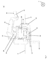
- Fig. 7 shows the embodiment of the Fig. 5 and 6 , where in Fig. 7 the rear handle 30 is shown in its swung-out state AZ. In the pivoted-out state AZ, the receiving bay 50 is released for attaching or removing the replaceable battery 200. In Fig. 7 the removable battery 200 is removed from the receiving bay.
- the pivoted state EZ of the rear handle 30 in Fig. 6 is in Fig. 7 the fully swung out state AZ with a pivoting angle of about 80 degrees (see. Fig. 7 , defined in the counterclockwise direction).
- a locking mechanism 40 is formed, with which the rear handle 30 in its pivoted state EZ (see. FIG. 6 ) and can be released as needed for a pivoting movement.
- the locking mechanism 40 has a mechanical switching element 46, by means of which a mounted on the rear handle 30 pin 45 (see. Fig. 9 ) which in a corresponding recess 48 (see. Fig. 7 and 8th ) can intervene, can be locked.
- the recess 48 is formed for the pin 45 on a stabilizing rail 59 which is disposed below the receiving bay 50.
- the switching element 45 is received in the recess 48, which in Fig. 5 is shown.
- a safety switch 65 the in Fig. 8 embodiment shown is disposed within the recess 48 and by the pin 45 (see. Fig. 9 ) can be operated.
- the safety switch 65 is designed to interrupt a power supply to the electric motor 60 in the unlocked state of the locking mechanism 40 and in the presence of the swung-out state AZ. If the locking mechanism 40 is locked or the rear handle 30 is pivoted in, as shown in FIG Fig. 5 the case is, the safety switch 65 signals that the electric motor 60 may be actuated.
- the circular saw 100 has a stabilizing rail 59.
- This stabilizing rail 59 is designed to provide the rear handle 30 with a contact surface in which the recess 48 is formed. If the rear handle 30 is in the pivoted-in state EZ, located (cf. Fig. 5 ), the rear handle 30 is secured by the pin 45 against undesirable rotation transverse to the pivot axis S.
- a rail guide 55 is formed, via which the replacement battery 200 can be inserted into the receiving bay 50 and pulled out of it.
- the rail guide 55 is designed such that a withdrawal of the removable battery 200 is possible only after actuation of a release element 58 on the removable battery 200.
- Fig. 8 it can be seen, protrudes a actuated by the release element 58 latching lug 59 in a corresponding recess (not shown) on the underside of the rail 15 into it.
- motor shaft 61 of the electric motor 60 is parallel to the rotation axis R of the designed as a saw blade tool 90.
- motor shaft 61 and axis of rotation 60 can extend coaxially in all embodiments.
- a parallel offset course of 61 and rotation axis 60 is (as shown) conceivable when For example, a gear between the motor shaft 61 and saw blade 90 is provided.
- Hand tool 100 designed as a portable circular saw also has a detent mechanism 39, which is not shown here in more detail and which is designed to hold the rear handle 30 securely in the illustrated pivoted state AZ until a spring-locking force is overcome by the user.
- a maximum length L of hand-held power tool 100 designed as a portable circular saw, relative to feed direction V, is at least twice as long as a maximum width B of hand-held power tool 100 designed as a portable circular saw, perpendicular to feed direction V (cf. Fig. 8 ).
Abstract
Akkubetriebene Handwerkzeugmaschine (100), insbesondere Handkreissäge, mit einem Elektromotor zum rotatorischen Antreiben eines an der Handwerkzeugmaschine anzuordnenden Werkzeugs (90), einem, jeweils bezogen auf eine Vorschubrichtung (V) der Handwerkzeugmaschine, vorderen (20) und hinteren Handgriff (30), und mit einer Aufnahmebucht (50) zur Aufnahme eines Wechselakkus (200), wobei der hintere Handgriff um eine Schwenkachse (S) seitlich ausschwenkbar gelagert ist, derart dass, wenn der hintere Handgriff in einem ausgeschwenkten Zustand (AZ) befindlich ist, die Aufnahmebucht zur Auf- oder Entnahme des Wechselakkus freigegeben ist, und, wenn der hintere Handgriff in einem eingeschwenkten Zustand befindlich ist, die Auf- oder Entnahme des Wechselakkus in die oder aus der Aufnahmebucht gesperrt ist.Battery-operated hand tool machine (100), in particular circular saw, with an electric motor for rotatably driving a tool (90) to be arranged on the hand tool machine, one each in relation to a feed direction (V) of the hand tool machine, front (20) and rear handle (30), and with a receiving bay (50) for receiving a replaceable battery (200), wherein the rear handle is mounted laterally swingable about a pivot axis (S), such that, when the rear handle is in a swung-out state (AZ), the receiving bay for up - Is removed or removal of the removable battery, and when the rear handle is in a pivoted state, the up or removal of the removable battery is locked in or out of the receiving bay.
Description
Die vorliegende Erfindung betrifft eine akkubetriebene Handwerkzeugmaschine, insbesondere eine Handkreissäge, mit einem Elektromotor zum rotatorischen Antreiben eines an der Handwerkzeugmaschine anzuordnenden Werkzeugs, insbesondere eines Sägeblatts. Die Handwerkzeugmaschine weist, jeweils bezogen auf eine Vorschubrichtung der Handwerkzeugmaschine, einen vorderen und hinteren Handgriff auf. Ferner weist die Handwerkzeugmaschine eine Aufnahmebucht zur Aufnahme eines Wechselakkus auf. Der Wechselakku dient zur Versorgung des Elektromotors.The present invention relates to a battery-operated hand tool, in particular a circular saw, with an electric motor for rotationally driving a to be arranged on the power tool, in particular a saw blade. The hand tool has, in each case based on a feed direction of the power tool, a front and rear handle. Furthermore, the hand tool has a receiving bay for receiving a removable battery. The removable battery is used to supply the electric motor.
Solche Handwerkzeugmaschine sind grundsätzlich aus dem Stand der Technik bekannt. Ebenfalls aus dem Stand der Technik bekannt sind Handwerkzeugmaschinen, deren Elektromotor ausgebildet ist, über ein Schneckengetriebe der Handwerkzeugmaschine ein Werkzeug, z.B. in Form eines Sägeblatts, anzutreiben. Bei solchen als Handkreissäge ausgestalteten Handwerkzeugmaschinen, die insbesondere aus den USA bekannt sind und typischerweise als "worm-drive saw" (WDS) bezeichnet werden, erlaubt das Schneckengetriebe eine rechtwinklige Anordnung der Motorachse (Schneckenwelle) und der Werkzeugachse, d.h. Sägeblattachse (Abtriebsachse für das Sägeblatt). Dadurch weisen als WDS ausgebildete Handkreissägen eine längliche, weniger breite Form als in Europa bevorzugte "side winder" (SW) auf, bei denen Motorachse und Sägeblattachse koaxial, zumindest aber parallel zueinander angeordnet sind.Such hand tool machines are basically known from the prior art. Also known from the prior art are hand tool machines whose electric motor is formed via a worm gear of the power tool a tool, e.g. in the form of a saw blade, to power. In such hand-held power tool hand tools, which are known in particular from the USA and are typically referred to as "worm-drive saw" (WDS), the worm gear allows a right-angled arrangement of the motor shaft (worm shaft) and the tool axis, i. Saw blade axis (output axis for the saw blade). As a result, circular saws designed as WDS have an elongate, less broad shape than "side winder" (SW) preferred in Europe, in which the motor axis and saw blade axis are arranged coaxially, but at least parallel to one another.
Es ist Aufgabe der vorliegenden Erfindung, eine Handkreissäge mit verbesserter Handhabbarkeit bereitzustellen.It is an object of the present invention to provide a portable circular saw with improved handling.
Die Aufgabe wird dadurch gelöst, dass der hintere Handgriff um eine Schwenkachse seitlich ausschwenkbar gelagert ist, derart, dass, wenn der hintere Handgriff in einem ausgeschwenkten Zustand befindlich ist, die Aufnahmebucht zur Auf- oder Entnahme des Wechselakkus freigegeben ist, und, wenn der hintere Handgriff in einem eingeschwenkten Zustand befindlich ist, die Auf- oder Entnahme des Wechselakkus in die oder aus der Aufnahmebucht gesperrt ist.The object is achieved in that the rear handle is mounted laterally pivotable about a pivot axis, such that when the rear handle is in a swung-out state, the receiving bay for receiving or removing the removable battery is released, and if the rear Handle is located in a pivoted state, the up or removal of the removable battery is locked in or out of the receiving bay.
Vorteilhafterweise erlaubt die erfindungsgemäße akkubetriebene Handwerkzeugmaschine ein besonders leichtes Einbringen beziehungsweise Entnehmen eines Wechselakkus. Bereits dadurch weist die erfindungsgemäße Handkreissäge eine verbesserte Handhabbarkeit gegenüber aus dem Stand der Technik bekannten akkubetriebenen Handwerkzeugmaschinen, insbesondere Handkreissägen, auf.Advantageously, the battery-powered hand tool according to the invention allows a particularly easy insertion or removal of a removable battery. For this reason, the portable circular saw according to the invention has improved handling compared to known from the prior art battery-powered portable power tools, especially circular saws, on.
Die Erfindung schließt darüber hinaus die Erkenntnis ein, dass die längliche, weniger breite Form der als WDS ausgebildeten Handkreissägen des Standes der Technik eine kopflastige Ergonomie bedingt, die für sogenannte "drop cuts", also Schnitte in vertikaler Richtung von oben nach unten, bevorzugt sind. Dadurch, dass die Aufnahmebucht zur Aufnahme des Wechselakkus durch Schwenken des hinteren Handgriffs freigebbar ist, wird neben dem bereits erwähnten vorteilhaft einfachen Akkuwechsel auch die bevorzugte Ergonomie einer als WDS ausgebildeten Handkreissäge konstruktiv zumindest begünstigt.The invention further includes the recognition that the elongated, less broad shape of the prior art circular saws of the prior art designed as WDS requires top-heavy ergonomics, which are preferred for so-called "drop cuts", ie cuts in the vertical direction from top to bottom , Due to the fact that the receiving bay for receiving the removable battery can be released by pivoting the rear handle, the preferred ergonomics of a portable circular saw designed as a WDS are at least favored in addition to the already mentioned advantageously simple battery change.
Vorzugsweise ist eine Länge der Handwerkzeugmaschine entlang der Vorschubrichtung wenigstens doppelt so groß wie eine Breite der Handwerkzeugmaschine quer zur Vorschubrichtung. Unter Vorschubrichtung soll im Rahmen der vorliegenden Erfindung eine Schubrichtung beim bestimmungsgemäßen Arbeiten mit der Handwerkzeugmaschine zu verstehen sein, das heißt insbesondere nicht eine möglicherweise zeitweise eingenommene Schubrichtung zum Lösen eines verklemmten Werkzeugs, insbesondere eines Sägeblatts, aus einem Sägestück.Preferably, a length of the power tool along the feed direction is at least twice as large as a width of the power tool transverse to the feed direction. Feed direction is to be understood in the context of the present invention, a thrust direction when working properly with the power tool, ie in particular not a possibly temporarily assumed thrust direction for releasing a jammed tool, in particular a saw blade, from a saw.
In einer besonders bevorzugten Ausgestaltung ist die Schwenkachse in Vorschubrichtung der Handkreissäge orientiert. Vorzugsweise weist die Schwenkachse einen Schwenkpunkt auf der oberhalb, bevorzugt ausschließlich oberhalb, einer Bodenebene liegt und/oder unterhalb, vorzugsweise ausschließlich unterhalb, einer zu dieser Bodenebene parallelen Parallelebene liegt. Die Bodenebene kann durch eine im Arbeitsbetrieb ein Werkstück berührende Unterseite einer in Null-Grad-Stellung befindlichen und/oder einer auf maximale Schnitttiefe eingerichteten Bodenplatte der Handwerkzeugmaschine aufgespannt sein. Die Bodenplatte ist in Null-Grad-Stellung befindlich, wenn die im Arbeitsbetrieb ein Werkstück berührende Unterseite der Bodenplatte senkrecht zum flächigen Sägeblatt steht.In a particularly preferred embodiment, the pivot axis is oriented in the feed direction of the circular saw. Preferably, the pivot axis has a pivot point on which lies above, preferably exclusively above, a ground plane and / or below, preferably exclusively below, a parallel plane parallel to this ground plane. The ground plane can be spanned by a underside of a base plate of the handheld power tool that is in a zero-degree position and / or has been set to a maximum depth of cut. The bottom plate is located in zero-degree position when the underside of the bottom plate contacting a workpiece in working mode is perpendicular to the flat saw blade.
Die zur Bodenebene parallele Parallelebene weist vorzugsweise einen Abstand zur Bodenebene auf. In einer bevorzugten Ausgestaltung liegt vorzugsweise die Rotationsachse des Werkzeugs in der Parallelebene. In dieser bevorzugten Ausgestaltung ist der Schwenkpunkt vorzugsweise unterhalb der Aufnahmebucht angeordnet und besonders bevorzugt in einer Stabilisierungsschiene der Handwerkzeugmaschine ausgebildet. Mit anderen Worten ist in dieser bevorzugten Ausgestaltung der hintere Handgriff "unten" an der Handkreissäge angeschlagen.The plane parallel to the ground plane parallel plane preferably has a distance from the ground plane. In a preferred embodiment, the axis of rotation of the tool is preferably in the parallel plane. In this preferred embodiment, the pivot point is preferably arranged below the receiving bay and particularly preferably formed in a stabilizing rail of the power tool. In other words, in this preferred embodiment, the rear handle "down" struck on the circular saw.
Es hat sich als vorteilhaft herausgestellt, wenn der Schwenkpunkt vorzugsweise ausschließlich in einer dem hinteren Handgriff zugewandten Raumseite einer Achsebene liegt, wobei die Achsebene durch die Rotationsachse und einen Radius des Werkzeugs aufgespannt ist. Vorzugsweise schließt die Achsebene ausgehend von einem in Vorschubrichtung vor der Rotationsachse gelegenen Abschnitt einer Bodenebene und in Drehrichtung des Werkzeugs, einen Winkel von 90 Grad ein.It has been found to be advantageous if the pivot point is preferably located exclusively in a room side facing the rear handle side of an axial plane, wherein the axial plane is spanned by the axis of rotation and a radius of the tool. The axial plane preferably encloses an angle of 90 degrees, starting from a section of a ground plane located in front of the axis of rotation in the feed direction and in the direction of rotation of the tool.
Ebenfalls bevorzugt liegt der Schwenkpunkt, vorzugsweise ausschließlich, in einer dem vorderen Handgriff zugewandten Raumseite einer Abstandsebene ABE. Bevorzugt ist die Abstandsebene parallel zur Achsebene und/oder ist weist zu der Achsebene einen Abstand auf, der wenigstens so groß und/oder höchstens doppelt so groß ist, wie ein maximal möglicher Werkzeugdurchmesser einer jeweiligen Handwerkzeugmaschine.Also preferably, the pivot point, preferably exclusively, lies in a space side of a distance plane ABE facing the front handle. Preferably, the distance plane is parallel to the axial plane and / or has to the axial plane at a distance which is at least as large and / or at most twice as large as a maximum possible tool diameter of a respective hand tool.
Der Schwenkpunkt kann, vorzugsweise ausschließlich, in einer dem vorderen Handgriff zugewandten Raumseite einer Handgriffebene liegen. Vorzugsweise wird die Handgriffebene durch die Rotationsachse und einen Radius des Werkzeugs aufgespannt, wobei die Handgriffebene, ausgehend von einem in Vorschubrichtung hinter der Rotationsachse gelegenen Abschnitt einer Bodenebene und in entgegengesetzter Drehrichtung des Werkzeugs, einen Winkel von wenigstens 20 Grad und vorzugsweise wenigstens 30 Grad einschließt. In dieser bevorzugten Ausgestaltung ist der Schwenkpunkt vorzugsweise oberhalb der Aufnahmebucht angeordnet und besonders bevorzugt in einer Profilschiene der Handwerkzeugmaschine ausgebildet. Mit anderen Worten in dieser bevorzugten Ausgestaltung der hintere Handgriff "oben" an der Handwerkzeugmaschine angeschlagen.The pivot point may, preferably exclusively, lie in a space side of a handle plane facing the front handle. Preferably, the handle plane is clamped by the axis of rotation and a radius of the tool, wherein the handle plane, starting from a lying in the feed direction behind the rotation axis portion of a ground plane and in the opposite direction of rotation of the tool, an angle of at least 20 degrees and preferably at least 30 degrees. In this preferred embodiment, the pivot point is preferably arranged above the receiving bay and particularly preferably formed in a rail of the power tool. In other words, in this preferred embodiment, the rear handle "top" posted on the power tool.
Es sei an dieser Stelle ausdrücklich darauf hingewiesen, dass die gerade definierten Lagebedingungen der Schwenkachse sowohl für sich genommen als auch in Kombination gelten können. Derart schließen beispielsweise die Bodenebene, die Achsebene, die Abstandsebene und die Parallelebene einen Raumbereich in Form eines Quaders ein, in dem der Schwenkpunkt angeordnet bzw. anzuordnen ist.At this point it should be expressly pointed out that the currently defined positional conditions of the pivot axis can apply both individually and in combination. For example, include the ground plane, the axial plane, the distance plane and the parallel plane, a space area in the form of a cuboid, in which the pivot point is arranged or to be arranged.
In einer bevorzugten Ausgestaltung liegt der Schwenkpunkt in einer Stabilisierungsschiene der Handwerkzeugmaschine. Alternativ kann der Schwerpunkt in einer Profilschiene der Handwerkzeugmaschine liegen. Die Schwenkachse kann durch einen Zylinderstift verlaufen, der in Stiftaufnahme gelagert ist.In a preferred embodiment, the pivot point is in a stabilizing rail of the power tool. Alternatively, the center of gravity may lie in a profile rail of the power tool. The pivot axis may extend through a cylindrical pin which is mounted in pin holder.
Es hat sich als vorteilhaft herausgestellt, wenn ein durch einen Schwenkanschlag und einen Gegenanschlag beschränkter Schwenkwinkel wischen eingeschwenkten Zustand und ausgeschwenkten des hinteren Handgriffs größer als 30 Grad ist, vorzugsweise 90 Grad beträgt und höchsten 330 Grad ist.It has proven to be advantageous if a limited by a pivot stop and a counter-stop swing angle swiveled state and swung out of the rear handle is greater than 30 degrees, preferably 90 degrees and highest 330 degrees.
Bevorzugt weist die Handwerkzeugmaschine einen Rastmechanismus auf, der ausgebildet ist, den hinteren Handgriff in dem ausgeschwenkten Zustand sicher zu halten, vorzugsweise bis zum Überwinden einer Federsperrkraft durch den Anwender.Preferably, the hand tool machine has a latching mechanism which is designed to securely hold the rear handle in the swung-out state, preferably until overcoming a spring-locking force by the user.
Die Federsperrkraft kann beispielsweise durch ein Druckstück mit Kugel und Feder und wenigstens einer korrespondierenden Rastvertiefung ausgebildet sein. Vorzugsweise ist ein derartiger Mechanismus nahe der Schwenkachse ausgebildet, was einen besonders kompakten Aufbau ermöglicht. Der Rastmechanismus kann alternativ durch eine magnetische Paarung, vorzugsweise im Bereich des Schwenkanschlags und/oder des Gegenanschlags, ausgebildet sein. Ebenfalls ist es möglich, den Rastmechanismus mittels Schlingfederreibung zu realisieren. Jede dieser Möglichkeiten ist derart ausgestaltet, dass der hintere Handgriff so lange in dem ausgeschwenkten Zustand sicher gehalten wird, bis eine durch den Anwender auf den hinteren Handgriff aufgebrachte Kraft die Federsperrkraft des Rastmechanismus überwindet.The spring-locking force can be formed for example by a pressure piece with ball and spring and at least one corresponding detent recess. Preferably, such a mechanism is formed near the pivot axis, which allows a particularly compact structure. The latching mechanism may alternatively be formed by a magnetic pairing, preferably in the region of the pivot stop and / or the counter-stop. It is also possible to realize the locking mechanism by means of loop spring friction. Each of these options is configured such that the rear handle is held securely in the pivoted-out state until a force applied by the user to the rear handle overcomes the spring-locking force of the detent mechanism.
In einer besonders bevorzugten Ausgestaltung weist der hintere Handgriff einen Verriegelungsmechanismus auf, der ausgebildet ist, den hinteren Handgriff in seinem eingeschwenkten Zustand zu fixieren und/oder bedarfsweise für eine Schwenkbewegung freizugeben. Es hat sich als vorteilhaft herausgestellt, wenn unterhalb der Aufnahmebucht eine Stabilisierungsschiene angeordnet ist, die vorzugsweise entgegen der Vorschubrichtung über die Aufnahmebucht hinaus kragt und an der der hintere Handgriff in seinem eingeschwenkten Zustand vorzugsweise fixiert werden kann.In a particularly preferred embodiment, the rear handle on a locking mechanism which is adapted to fix the rear handle in its pivoted state and / or release, if necessary, for a pivoting movement. It has proven to be advantageous if below the receiving bay a stabilizing rail is arranged, which preferably projects against the feed direction beyond the receiving bay out and on which the rear handle can be preferably fixed in its pivoted state.
Eine Fixierung des hinteren Handgriffs in seinem eingeschwenkten Zustand an der Stabilisierungsschiene ermöglicht eine hohe Stabilität des hinteren Handgriffs und somit einen optimalen Kraftfluss in Vorschubrichtung der Handwerkzeugmaschine.A fixation of the rear handle in its pivoted state on the stabilizing rail allows a high stability of the rear handle and thus an optimal power flow in the feed direction of the power tool.
Es hat sich als vorteilhaft herausgestellt, wenn der Verriegelungsmechanismus einen Zapfen umfasst, der in eine dafür vorgesehene Ausnehmung, die vorzugsweise an der Stabilisierungsschiene oder Profilschiene ausgebildet ist, eingreifen kann. Gemäß einer alternativen Ausgestaltungsform kann der Verriegelungsmechanismus auch durch einen Haken mit einer entsprechenden Öse ausgestaltet sein. Dies vorzugsweise wenn der hintere Handgriff im eingeschwenkten Zustand ist. Über einen solchen Verriegelungsmechanismus wird der hintere Handgriff derart verriegelt, dass ein besonders sicherer Betrieb der Handwerkzeugmaschine durch Vermeiden eines ungewünschten Schwenkens des hinteren Handgriffs realisiert wird. Der Verriegelungsmechanismus kann ausgebildet sein, dass er bei eingeschwenktem Zustand selbsttätig verriegelt. Alternativ kann der Verriegelungsmechanismus ausgebildet sein, durch die Betätigung eines Bedienelements durch den Anwender verriegelt zu werden.It has proven to be advantageous if the locking mechanism comprises a pin which can engage in a recess provided for this, which is preferably formed on the stabilizing rail or rail. According to an alternative embodiment, the locking mechanism may also be configured by a hook with a corresponding eyelet. This is preferably when the rear handle is in the pivoted state. About such a locking mechanism, the rear handle is locked so that a particularly safe operation of the power tool is achieved by avoiding unwanted pivoting of the rear handle. The locking mechanism may be configured to assist in swung automatically locked state. Alternatively, the locking mechanism may be configured to be locked by operation of an operating member by the user.
Bevorzugt wird die Sicherheit der Handkreissäge dadurch erhöht, dass diese einen Sicherheitsschalter aufweist, der mit dem hinteren Handgriff verbunden ist und ausgebildet ist, in dem entriegelten Zustand des Verriegelungsmechanismus und/oder beim Vorliegen des ausgeschwenkten Zustands eine Stromzufuhr zum Elektromotor zu unterbrechen. Der Sicherheitsschalter kann unmittelbar die Hauptstromversorgung der Handwerkzeugmaschine unterbrechen oder aber einer Elektronik den Zustand des Verriegelungsmechanismus übermitteln und über eine in der Elektronik vorgesehene Logik ein Anlaufen der Handwerkzeugmaschine, insbesondere einer Säge, trotz Drückens des Ein/Aus-Schalters unterbinden. Der Sicherheitsschalter kann elektrisch, magnetisch und/oder optisch ausgebildet sein. Mehrere Möglichkeiten der Anordnung des Sicherheitsschalters sind denkbar. Der Sicherheitsschalter kann beispielsweise Teil des mechanischen Schaltelements sein oder mit diesem mechanisch verbunden sein. Alternativ oder zusätzlich kann der Sicherheitsschalter im Bereich der Schwenkachse oder des Schwenkpunts des hinteren Handgriffs angeordnet sein. Alternativ oder zusätzlich ist es denkbar, den Sicherheitsschalter in einem Bereich des hinteren Handgriffs anzuordnen, der bei eingeschwenktem Zustand des hinteren Handgriffs in Kontakt mit einem in der Aufnahmebucht aufgenommenen Wechselakku steht. Es wurde als vorteilhaft erkannt, den Sicherheitsschalter als Teil des mechanischen Schaltelements auszubilden.Preferably, the safety of the portable circular saw is increased by having a safety switch which is connected to the rear handle and is designed to interrupt a power supply to the electric motor in the unlocked state of the locking mechanism and / or in the presence of the swung-out state. The safety switch can immediately interrupt the main power supply of the power tool or an electronics transmit the state of the locking mechanism and prohibit a start in the electronic logic of a start of the power tool, in particular a saw, despite pressing the on / off switch. The safety switch can be electrical, magnetic and / or optical. Several ways of arranging the safety switch are conceivable. The safety switch may for example be part of the mechanical switching element or be mechanically connected thereto. Alternatively or additionally, the safety switch can be arranged in the region of the pivot axis or the pivot point of the rear handle. Alternatively or additionally, it is conceivable to arrange the safety switch in a region of the rear handle, which is in the swung-state of the rear handle in contact with a recorded in the receiving bay Wechselakku. It has been found advantageous to design the safety switch as part of the mechanical switching element.
In einer weiteren bevorzugten Ausgestaltung weist die Aufnahmebucht eine Schienenführung auf, über die der Wechselakku in die Aufnahmebucht eingeschoben und aus dieser herausgezogen werden kann. Vorzugsweise ist die Schienenführung und/oder der Wechselakku derart ausgebildet, dass ein Herausziehen des Wechselakkus erst nach Betätigung eines Freigabeelements möglich ist. Vorzugsweise ist das Freigabeelement als Knopf ausgebildet und am Wechselakku angeordnet.In a further preferred embodiment, the receiving bay on a rail guide over which the removable battery can be inserted into the receiving bay and pulled out of this. Preferably, the rail guide and / or the removable battery is designed such that a withdrawal of the removable battery is possible only after actuation of a release element. Preferably, the release element is designed as a button and arranged on the removable battery.
Es hat sich ebenfalls als vorteilhaft herausgestellt, wenn eine Handangriffsfläche des hinteren Handgriffs, bezogen auf die Vorschubrichtung der Handwerkzeugmaschine, hinter dem in der Aufnahmebucht aufgenommenen Wechselakku aufgenommen ist. In einer besonders bevorzugten Ausgestaltung ist das Werkzeug, bezogen auf die Vorschubrichtung der Handwerkzeugmaschine, links oder rechts vom Elektromotor angeordnet. Die Ausgangswelle des Elektromotors kann parallel zur Rotationsachse des Sägeblatts verlaufen. Die Handkreissäge ist vorzugsweise zumindest doppelt so lang wie breit. Vorzugsweise ist die Handkreissäge frei von einem Schneckengetriebe. Derart kann die beispielsweise als akkubetriebene Handkreissäge ausgestaltete Handwerkzeugmaschine die Ergonomie einer als WDS bereitgestellten und in Form einer Handkreissäge ausgestalteten Handwerkzeugmaschine erreichen.It has also been found to be advantageous if a hand engagement surface of the rear handle, based on the feed direction of the power tool, is added behind the recorded in the receiving bay removable battery. In a particularly preferred embodiment, the tool, based on the feed direction of the power tool, is arranged to the left or right of the electric motor. The output shaft of the electric motor may be parallel to the axis of rotation of the saw blade. The circular saw is preferably at least twice as long as it is wide. Preferably, the circular saw is free of a worm gear. Such, for example, as battery-powered portable circular saw configured hand tool reach the ergonomics of a provided as WDS and designed in the form of a circular saw handheld power tool.
Weitere Vorteile ergeben sich aus der folgenden Figurenbeschreibung. In den Figuren sind verschiedene Ausführungsbeispiele der vorliegenden Erfindung dargestellt. Die Figuren, die Beschreibung und die Ansprüche enthalten zahlreiche Merkmale in Kombination. Der Fachmann wird die Merkmale zweckmässigerweise auch einzeln betrachten und zu sinnvollen weiteren Kombinationen zusammenfassen.Further advantages will become apparent from the following description of the figures. In the figures, various embodiments of the present invention are shown. The figures, the description and the claims contain numerous features in combination. The skilled person will conveniently consider the features individually and summarize meaningful further combinations.
In den Figuren sind gleiche und gleichartige Komponenten mit gleichen Bezugszeichen beziffert.In the figures, identical and similar components are numbered with the same reference numerals.
Es zeigen:
- Fig.1
- ein erstes bevorzugtes Ausführungsbeispiel einer erfindungsgemäßen akkubetriebenen Handwerkzeugmaschine in Form einer Handkreissäge in Seitenansicht, wobei der hintere Handgriff unten angeschlagen ist;
- Fig. 2
- eine Rückansicht des Ausführungsbeispiels aus
Fig. 1 , wobei der hintere Handgriff im eingeschwenkten Zustand befindlich ist; - Fig. 3
- eine Rückansicht des Ausführungsbeispiels aus
Fig. 1 , wobei der hintere Handgriff im ausgeschwenkten Zustand befindlich ist; - Fig. 4
- eine perspektivische Darstellung der Ansicht aus
Fig. 3 , wobei der Wechselakku außerhalb der Aufnahmebucht befindlich ist; - Fig.5
- ein zweiten bevorzugtes Ausführungsbeispiel einer erfindungsgemäßen akkubetriebenen Handwerkzeugmaschine in Form einer Handkreissäge in Seitenansicht, wobei der hintere Handgriff oben angeschlagen ist;
- Fig. 6
- eine Rückansicht des Ausführungsbeispiels aus
Fig. 5 , wobei der hintere Handgriff im eingeschwenkten Zustand befindlich ist; - Fig. 7
- eine Rückansicht des Ausführungsbeispiels aus
Fig. 5 , wobei der hintere Handgriff im ausgeschwenkten Zustand befindlich ist; - Fig. 8
- eine perspektivische Darstellung der Ansicht aus
Fig. 7 , wobei der Wechselakku außerhalb der Aufnahmebucht befindlich ist; - Fig. 9
- eine andere perspektivische Darstellung der Ansicht aus
Fig. 7 .
- Fig.1
- a first preferred embodiment of a battery-powered hand tool according to the invention in the form of a circular saw in side view, wherein the rear handle is struck down;
- Fig. 2
- a rear view of the embodiment
Fig. 1 wherein the rear handle is in the pivoted state; - Fig. 3
- a rear view of the embodiment
Fig. 1 wherein the rear handle is in the swung-out state; - Fig. 4
- a perspective view of the view
Fig. 3 wherein the removable battery is located outside the receiving bay; - Figure 5
- a second preferred embodiment of a battery-powered hand tool according to the invention in the form of a circular saw in side view, wherein the rear handle is struck above;
- Fig. 6
- a rear view of the embodiment
Fig. 5 wherein the rear handle is in the pivoted state; - Fig. 7
- a rear view of the embodiment
Fig. 5 wherein the rear handle is in the swung-out state; - Fig. 8
- a perspective view of the view
Fig. 7 wherein the removable battery is located outside the receiving bay; - Fig. 9
- another perspective view of the view
Fig. 7 ,
Ein bevorzugtes Ausführungsbeispiel einer als akkubetriebenen Handkreissäge ausgestalteten Handwerkzeugmaschine 100 ist in
Im bestimmungsgemäßen Betrieb wird die Handkreissäge 100 in Vorschubrichtung V vorgeschoben. Die Vorschubrichtung ist in
Des Weiteren weist die Handkreissäge 100 eine Aufnahmebucht 50 zur Aufnahme eines Wechselakkus 200 auf. In dem in
Erfindungsgemäß ist der hintere Handgriff 30 um eine Schwenkachse S schwenkbar gelagert. Der hintere Handgriff 30 ist derart um die Schwenkachse S schwenkbar gelagert, dass, wenn der hintere Handgriff 30 in einem ausgeschwenkten Zustand (vgl.
Wie aus einer Zusammenschau von
Bei einem bevorzugten Ausführungsbeispiel der
Die Schwenkachse S verläuft ausschließlich oberhalb einer Bodenebene GE. Die Bodenebene GE kann auch als Grundplattenebene ausgestaltet sein. Die Bodenebene GE entspricht dabei der Grundplattenebene. Hierbei weist die als Handkreissäge ausgestaltete Handwerkzeugmaschine 100 eine Bodenplatte 10 auf. Die Bodenplatte kann auch als Grundplatte bezeichnet werden. Dies ist insbesondere der Fall, wenn die Handwerkzeugmaschine eine Grundplatte enthält. Es ist jedoch auch möglich, dass die Handwerkzeugmaschine 100 keine Bodenplatte 10 bzw. Grundplatte enthält. Eine als Bodenebene ausgestaltete Bodenebene GE wird durch eine im Arbeitsbetrieb ein Werkstück berührende Unterseite 11 einer Null-Grad-Stellung befindlichen und auf maximale Schnitttiefe eingerichteten Bodenplatte 10 der Handkreissäge 100 aufgespannt. Die durch Unterseite 11 der Bodenplatte 10 aufgespannte Bodenebene GE ist ebenfalls in der perspektivischen Darstellung der
In
Ebenfalls in
Ebenfalls in
Die Bodenebene GE, die Achsebene AE, die Abstandsebene ABE und die Parallelebene PE schließen einen Raumbereich in Form eines Quaders ein, in dem der Schwenkpunkt SP angeordnet ist. Wie ebenfalls der
Mit Bezug auf
Der hintere Handgriff 30 ist durch einen Zylinderstift 70, der koaxial zur Schwenkachse S verläuft, in einer Stiftaufnahme 71 einer Stabilisierungsschiene 59 der Handkreissäge 100 schwenkbar gelagert. Zu diesem Zweck weist der hintere Handgriff 30 eine hier nicht dargestellte Bohrung auf, durch die der Zylinderstift 70 verläuft.
Mit Bezug auf
Im Ausführungsbeispiel der
Im Folgenden sollen mit Bezug auf
Wie der
In
Wie ebenfalls der
Unterhalb der Profilschiene 15 ist eine Schienenführung 55 ausgebildet, über die der Wechselakku 200 in die Aufnahmebucht 50 eingeschoben und aus dieser herausgezogen werden kann. Die Schienenführung 55 ist derart ausgebildet, dass ein Herausziehen des Wechselakkus 200 erst nach Betätigung eines Freigabeelements 58 am Wechselakku 200 möglich ist. Aus
Eine in
Eine maximale Länge L der als Handkreissäge ausgestalteten Handwerkzeugmaschine 100, bezogen auf die Vorschubrichtung V, ist zumindest doppelt so lang wie eine maximale Breite B der als Handkreissäge ausgestalteten Handwerkzeugmaschine 100, senkrecht zur Vorschubrichtung V.A maximum length L of the
Ein zweites bevorzugtes Ausführungsbeispiel einer akkubetriebenen Handkreissäge 100 ist in
Im bestimmungsgemäßen Betrieb wird die Handkreissäge 100 in Vorschubrichtung V vorgeschoben. Die Vorschubrichtung ist in
Des Weiteren weist die Handkreissäge 100 eine Aufnahmebucht 50 zur Aufnahme eines Wechselakkus 200 auf. In dem in
Erfindungsgemäß ist der hintere Handgriff 30 um eine Schwenkachse S schwenkbar gelagert. Der hintere Handgriff 30 ist derart um die Schwenkachse S schwenkbar gelagert, dass, wenn der hintere Handgriff 30 in einem ausgeschwenkten Zustand (vgl.
Wie aus einer Zusammenschau von
Bei dem Ausführungsbeispiel der
Die Schwenkachse S weist einen Schwenkpunkt SP auf, der ausschließlich oberhalb einer Bodenebene GE liegt. Die Bodenebene GE wird durch eine im Arbeitsbetrieb ein Werkstück berührende Unterseite 11 einer Null-Grad-Stellung befindlichen und auf maximale Schnitttiefe eingerichteten Bodenplatte 10 der Handkreissäge 100 aufgespannt. Die durch Unterseite 11 der Bodenplatte 10 aufgespannte Bodenebene GE ist ebenfalls in der rückseitigen Darstellung der
Ebenfalls in
Ebenfalls in
Ebenfalls in
Die Handgriffebene HE, die Achsebene AE, die Abstandsebene EBA und die Bodenebene definieren im vorliegend dargestellten Ausführungsbeispiel einen stumpfkeilförmigen Raumbereich, der frei von dem Schwenkpunkt 15 ist.The handle plane HE, the axis plane AE, the distance plane EBA and the ground plane define in the presently illustrated embodiment, a truncated-wedge-shaped space area which is free of the
Mit Bezug auf
Im Folgenden sollen mit Bezug auf die
Am hinteren Handgriff 30 der Handkreissäge 100 ist ein Verriegelungsmechanismus 40 ausgebildet, mit dem der hintere Handgriff 30 in seinem eingeschwenkten Zustand EZ (vgl.
Wie den
In
Wie ebenfalls der
Unterhalb einer von der Handkreissäge umfassten Profilschiene 15 ist eine Schienenführung 55 ausgebildet, über die der Wechselakku 200 in die Aufnahmebucht 50 eingeschoben und aus dieser herausgezogen werden kann. Die Schienenführung 55 ist derart ausgebildet, dass ein Herausziehen des Wechselakkus 200 erst nach Betätigung eines Freigabeelements 58 am Wechselakku 200 möglich ist. Aus
Eine in
Eine maximale Länge L der als Handkreissäge ausgestalteten Handwerkzeugmaschine 100, bezogen auf die Vorschubrichtung V, ist zumindest doppelt so lang wie eine maximale Breite B der als Handkreissäge ausgestalteten Handwerkzeugmaschine 100, senkrecht zur Vorschubrichtung V (vgl.
- 1010
- Bodenplattebaseplate
- 1111
- Unterseite der BodenplatteBottom of the bottom plate
- 1212
- vorlaufender Abschnittleading section
- 1313
- nachlaufender Abschnitttrailing section
- 1515
- Profilschienerail
- 2020
- vorderer Handgrifffront handle
- 2525
- Griffträger des vorderen HandgriffsHandle carrier of the front handle
- 3030
- hinterer Handgriffrear handle
- 3131
- HandangriffsflächeHand-gripping surface
- 3232
- Schwenkabschnittpivot portion
- 3434
- Schwenkanschlagswivel stop
- 3636
- Gegenanschlagcounterstop
- 3838
- Profil des SchwenkarmsProfile of the swivel arm
- 3939
- Rastmechanismusdetent mechanism
- 4040
- Verriegelungsmechanismuslocking mechanism
- 4545
- Zapfenspigot
- 4646
- mechanisches Schaltelementmechanical switching element
- 4848
- Ausnehmungrecess
- 5050
- Aufnahmebuchtreceiving bay
- 5555
- Schienenführungrail guide
- 5858
- Freigabeelementrelease element
- 5959
- Stabilisierungsschienestabilizing rail
- 6060
- Elektromotorelectric motor
- 6161
- Motorwellemotor shaft
- 6565
- Sicherheitsschaltersafety switch
- 7070
- Zylinderstiftstraight pin
- 7171
- Stiftaufnahmepin receptacle
- 9090
- WerkzeugTool
- 100100
- HandwerkzeugmaschineHand tool
- 200200
- Wechselakkuremovable battery
- AEAE
- Achsebeneaxial plane
- ABEABE
- Abstandsebeneclearance plane
- GEGE
- Bodenebeneground level
- PEPE
- Parallelebeneparallel plane
- DD
- Drehachseaxis of rotation
- RR
- Rotationsachseaxis of rotation
- RA, RA'RA, RA '
- Radiusradius
- SS
- Schwenkachseswivel axis
- SWSW
- Schwenkwinkelswivel angle
- VV
- Vorschubrichtungfeed direction
Claims (16)
dadurch gekennzeichnet, dass der hintere Handgriff (30) um eine Schwenkachse (S) vorzugsweise seitlich ausschwenkbar gelagert ist, derart dass, wenn der hintere Handgriff (30) in einem ausgeschwenkten Zustand (AZ) befindlich ist, die Aufnahmebucht (50) zur Auf- oder Entnahme des Wechselakkus (200) freigegeben ist, und, wenn der hintere Handgriff (30) in einem eingeschwenkten Zustand (EZ) befindlich ist, die Auf- oder Entnahme des Wechselakkus (200) in die oder aus der Aufnahmebucht (50) gesperrt ist.Battery-powered hand tool (100), in particular circular saw, with an electric motor (60) for rotatably driving a tool (90) to be arranged on the hand tool (100), one (20) in each case relative to a feed direction (V) of the hand tool (100) ) and rear handle (30), and with a receiving bay (50) for receiving a replaceable battery (200),
characterized in that the rear handle (30) about a pivot axis (S) is preferably mounted laterally swingable, such that when the rear handle (30) is in a swung-out state (AZ), the receiving bay (50) for Aufauf or removal of the removable battery (200) is released, and, when the rear handle (30) is in a pivoted state (EZ), the up or removal of the removable battery (200) is locked in or out of the receiving bay (50) ,
dadurch gekennzeichnet, dass die Schwenkachse (S) in Vorschubrichtung (V) der Handwerkzeugmaschine (100) orientiert ist und die Schwenkachse (S) einen Schwenkpunkt (SP) aufweist, der oberhalb einer Bodenebene (GE) und/oder unterhalb einer zu dieser Bodenebene (GE) parallelen Parallelebene (PE) liegt, wobei die Bodenebene (GE) durch eine im Arbeitsbetrieb ein Werkstück berührende Unterseite (11) einer in Null-Grad-Stellung befindlichen und auf maximale Schnitttiefe eingerichteten Bodenplatte (10) der Handwerkzeugmaschine (100) aufgespannt wird.Hand tool (100) according to claim 1,
characterized in that the pivot axis (S) in the feed direction (V) of the power tool (100) is oriented and the pivot axis (S) has a pivot point (SP) above a ground plane (GE) and / or below one to this ground plane ( GE) parallel parallel plane (PE), wherein the bottom plane (GE) by a working operation in a workpiece contacting underside (11) of a zero-degree position and adapted to maximum depth of cut bottom plate (10) of the power tool (100) is clamped ,
dadurch gekennzeichnet, dass der Schwenkpunkt vorzugsweise ausschließlich in einer dem hinteren Handgriff (30) zugewandten Raumseite einer Achsebene (AE) liegt, wobei die Achsebene (AE) durch die Rotationsachse (R) und einen Radius (RA) des Werkzeugs (90) aufgespannt ist, wobei die Achsebene (AE), ausgehend von einem in Vorschubrichtung (V) vor der Rotationsachse (R) gelegenen Abschnitt (11) einer Bodenebene (GE) und in Drehrichtung (DR) des Werkzeugs (90), einen Winkel von 90 Grad einschließt.Hand tool (100) according to claim 2,
characterized in that the pivot point is preferably exclusively in a the rear handle (30) facing the space side of an axial plane (AE), wherein the axial plane (AE) by the rotation axis (R) and a radius (RA) of the tool (90) is clamped in that the axial plane (AE) forms an angle of 90 degrees, starting from a section (11) of a ground plane (GE) located in the feed direction (V) in front of the axis of rotation (R) and in the direction of rotation (DR) of the tool (90) ,
dadurch gekennzeichnet, dass der Schwenkpunkt (SP) vorzugsweise ausschließlich in einer dem vorderen Handgriff (20) zugewandten Raumseite einer Abstandsebene (ABE) liegt, wobei die Abstandsebene (ABE) parallel zur Achsebene (AE) ist und zu dieser Achsebene (AE) einen Abstand (AS) aufweist, der genau so groß und/oder höchstens doppelt so groß ist, wie ein maximal möglicher Werkzeugdurchmesser (DB) einer jeweiligen Handwerkzeugmaschine (100).Hand tool (100) according to claim 2 or 3,
characterized in that the pivot point (SP) is preferably exclusively in one of the front handle (20) facing space side of a distance plane (ABE), wherein the distance plane (ABE) is parallel to the axial plane (AE) and to this axial plane (AE) a distance (AS), which is just as large and / or at most twice as large as a maximum possible tool diameter (DB) of a respective hand tool (100).
dadurch gekennzeichnet, dass der Schwenkpunkt (SP) vorzugsweise ausschließlich in einer dem vorderen Handgriff (20) zugewandten Raumseite einer Handgriffebene (HE) liegt, wobei die Handgriffebene (HE) durch die Rotationsachse (R) und einen Radius (RA) des Werkzeugs (90) aufgespannt ist, wobei Handgriffebene (HE), ausgehend von einem in Vorschubrichtung (V) hinter der Rotationsachse (R) gelegenen Abschnitt (13) einer Bodenebene (GE) und in entgegengesetzter Drehrichtung (D') des Werkzeugs (90), einen Winkel von wenigstens 20 Grad und vorzugsweise wenigstens 30 Grad einschließt.Hand tool (100) according to one of claims 2 to 4,
characterized in that the pivot point (SP) is preferably exclusively in a front side of the handle (20) facing space side of a handle plane (HE), wherein the handle plane (HE) by the rotation axis (R) and a radius (RA) of the tool (90 ), wherein handle plane (HE), starting from a in the feed direction (V) located behind the rotation axis (R) portion (13) of a ground plane (GE) and in the opposite direction of rotation (D ') of the tool (90), an angle of at least 20 degrees and preferably at least 30 degrees.
dadurch gekennzeichnet, dass die Schwenkachse (S) durch einen Zylinderstift (70) verläuft, der in einer Stiftaufnahme (71) gelagert ist.Hand tool (100) according to one of the preceding claims,
characterized in that the pivot axis (S) by a cylindrical pin (70) extends, which is mounted in a pin receptacle (71).
dadurch gekennzeichnet, dass ein durch einen Schwenkanschlag (34) und einen Gegenanschlag (36) beschränkter Schwenkwinkel (SW) zwischen eingeschwenkten Zustand (EZ) und ausgeschwenkten (AZ) des hinteren Handgriffs (30) größer als 30 Grad ist, vorzugsweise 90 Grad beträgt und höchsten 330 Grad ist.Hand tool (100) according to one of the preceding claims,
characterized in that a by a pivot stop (34) and a counter-stop (36) limited pivot angle (SW) between pivoted state (EZ) and swung (AZ) of the rear handle (30) is greater than 30 degrees, preferably 90 degrees and highest 330 degrees.
dadurch gekennzeichnet, dass die Handwerkzeugmaschine (100) einen Rastmechanismus (39) aufweist, der ausgebildet ist, den hinteren Handgriff (30) in dem ausgeschwenkten Zustand sicher zu halten, vorzugsweise bis zum Überwinden einer Federsperrkraft durch den Anwender.Hand tool (100) according to one of the preceding claims,
characterized in that the hand tool machine (100) comprises a latching mechanism (39) adapted to securely hold the rear handle (30) in the swung-out state, preferably until overcoming a spring-locking force by the user.
dadurch gekennzeichnet, dass der hintere Handgriff (30) einen Verriegelungsmechanismus (40) aufweist, der ausgebildet ist, den hinteren Handgriff (30) in seinem eingeschwenkten Zustand (EZ) zu fixieren und bedarfsweise für eine Schwenkbewegung freizugeben.Hand tool (100) according to one of the preceding claims,
characterized in that the rear handle (30) has a locking mechanism (40) which is adapted to fix the rear handle (30) in its swung-in state (EZ) and, if necessary, to release it for a pivoting movement.
dadurch gekennzeichnet, dass unterhalb der Aufnahmebucht (50) eine Stabilisierungsschiene (59) angeordnet ist, die vorzugsweise entgegen der Vorschubrichtung (V) über die Aufnahmebucht (50) hinaus auskragt und an der der hintere Handgriff (30) in seinem eingeschwenkten Zustand (EZ) fixiert werden kann.Hand tool (100) according to claim 9,
characterized in that below the receiving bay (50) a stabilizing rail (59) is arranged, which preferably protrudes counter to the feed direction (V) beyond the receiving bay (50) and on which the rear handle (30) in its pivoted state (EZ) can be fixed.
dadurch gekennzeichnet, dass der Verriegelungsmechanismus (40) einen Zapfen (46) umfasst, der in eine dafür vorgesehene Ausnehmung (48), die an der Stabilisierungsschiene (59) ausgebildet ist, eingreifen kann, wenn der hintere Handgriff (30) im eingeschwenkten Zustand ist.Hand tool (100) according to claim 10,
characterized in that the locking mechanism (40) comprises a pin (46) which is engageable with a recess (48) provided thereon formed on the stabilizing rail (59) when the rear handle (30) is in the pivoted state ,
dadurch gekennzeichnet, dass ein Sicherheitsschalter (65) mit dem hinteren Handgriff (30) verbunden ist und ausgebildet ist, in dem entriegelten Zustand des Verriegelungsmechanismus (40) und/oder beim Vorliegen des ausgeschwenkten Zustands eine Stromzufuhr zum Elektromotor (60) zu unterbrechen.Hand tool (100) according to one of claims 9 to 11,
characterized in that a safety switch (65) is connected to the rear handle (30) and adapted to interrupt a power supply to the electric motor (60) in the unlocked state of the locking mechanism (40) and / or in the presence of the pivoted state.
dadurch gekennzeichnet, dass die Aufnahmebucht (50) eine Schienenführung (55) aufweist über die der Wechselakku (200) in die Aufnahmebucht (50) eingeschoben und aus dieser heraus ausgezogen werden kann, wobei die Schienenführung (55) und/oder der Wechselakku (200) vorzugsweise derart ausgebildet ist, dass ein Herausziehen des Wechselakkus (200) erst nach Betätigung eines Freigabeelements (58) möglich ist.Hand tool (100) according to one of the preceding claims,
characterized in that the receiving bay (50) has a rail guide (55) via which the removable battery (200) in the receiving bay (50) can be inserted and pulled out therefrom, wherein the rail guide (55) and / or the removable battery (200 ) is preferably designed such that a withdrawal of the replaceable battery (200) is possible only after actuation of a release element (58).
dadurch gekennzeichnet, dass eine Handangriffsfläche (31) des hinteren Handgriffs (30), bezogen auf die Vorschubrichtung (V) der Handwerkzeugmaschine (100), hinter dem in der Aufnahmebucht (50) aufgenommenen Wechselakku (200) aufgenommen ist.A circular saw (100) according to any one of the preceding claims,
characterized in that a hand engagement surface (31) of the rear handle (30), relative to the feed direction (V) of the power tool (100), behind the in the receiving bay (50) recorded Wechselakku (200) is added.
dadurch gekennzeichnet, dass das Werkzeug (90), bezogen auf die Vorschubrichtung (V) der Handwerkzeugmaschine (100), links vom Elektromotor (60) angeordnet ist, die Ausgangswelle des Elektromotors (60) parallel zur Rotationsachse (R) des Werkzeugs (90) verläuft, und wobei die Handwerkzeugmaschine (100) zumindest doppelt so lang wie breit ausgebildet ist.A circular saw (100) according to any one of the preceding claims,
characterized in that the tool (90), relative to the feed direction (V) of the hand tool (100), is located to the left of the electric motor (60), the output shaft of the electric motor (60) parallel to the axis of rotation (R) of the tool (90) runs, and wherein the hand tool (100) is at least twice as long as wide.
dadurch gekennzeichnet, dass das Werkzeug (90), bezogen auf die Vorschubrichtung (V) der Handwerkzeugmaschine (100), rechts vom Elektromotor (60) angeordnet ist, die Ausgangswelle des Elektromotors (60) parallel zur Rotationsachse (R) des Werkzeugs (90) verläuft, und wobei die Handwerkzeugmaschine (100) zumindest doppelt so lang wie breit ausgebildet ist.A circular saw (100) according to any one of the preceding claims,
characterized in that the tool (90), relative to the feed direction (V) of the hand tool (100), is arranged to the right of the electric motor (60), the output shaft of the electric motor (60) parallel to the rotation axis (R) of the tool (90) runs, and wherein the hand tool (100) is at least twice as long as wide.
Priority Applications (5)
| Application Number | Priority Date | Filing Date | Title |
|---|---|---|---|
| EP15200669.8A EP3181306A1 (en) | 2015-12-17 | 2015-12-17 | Battery operated machine tool iii |
| US16/062,998 US20180370015A1 (en) | 2015-12-17 | 2016-12-13 | Battery-Powered Handheld Machine Tool |
| EP16819299.5A EP3389952B1 (en) | 2015-12-17 | 2016-12-13 | Battery operated machine tool iii |
| PCT/EP2016/080717 WO2017102678A1 (en) | 2015-12-17 | 2016-12-13 | Battery-powered hand-held machine tool iii |
| CN201680081968.9A CN108698220B (en) | 2015-12-17 | 2016-12-13 | Battery-operated hand-held power tool |
Applications Claiming Priority (1)
| Application Number | Priority Date | Filing Date | Title |
|---|---|---|---|
| EP15200669.8A EP3181306A1 (en) | 2015-12-17 | 2015-12-17 | Battery operated machine tool iii |
Publications (1)
| Publication Number | Publication Date |
|---|---|
| EP3181306A1 true EP3181306A1 (en) | 2017-06-21 |
Family
ID=54936841
Family Applications (2)
| Application Number | Title | Priority Date | Filing Date |
|---|---|---|---|
| EP15200669.8A Withdrawn EP3181306A1 (en) | 2015-12-17 | 2015-12-17 | Battery operated machine tool iii |
| EP16819299.5A Active EP3389952B1 (en) | 2015-12-17 | 2016-12-13 | Battery operated machine tool iii |
Family Applications After (1)
| Application Number | Title | Priority Date | Filing Date |
|---|---|---|---|
| EP16819299.5A Active EP3389952B1 (en) | 2015-12-17 | 2016-12-13 | Battery operated machine tool iii |
Country Status (4)
| Country | Link |
|---|---|
| US (1) | US20180370015A1 (en) |
| EP (2) | EP3181306A1 (en) |
| CN (1) | CN108698220B (en) |
| WO (1) | WO2017102678A1 (en) |
Cited By (2)
| Publication number | Priority date | Publication date | Assignee | Title |
|---|---|---|---|---|
| US20170197262A1 (en) * | 2016-01-13 | 2017-07-13 | Makita Corporation | Cutting device |
| US11097410B2 (en) * | 2015-12-17 | 2021-08-24 | Hilti Aktiengesellschaft | Battery-powered hand-held machine tool |
Families Citing this family (1)
| Publication number | Priority date | Publication date | Assignee | Title |
|---|---|---|---|---|
| EP3441193A1 (en) * | 2017-08-08 | 2019-02-13 | HILTI Aktiengesellschaft | Battery unit with locking mechanism |
Citations (5)
| Publication number | Priority date | Publication date | Assignee | Title |
|---|---|---|---|---|
| US6161293A (en) * | 1998-08-14 | 2000-12-19 | One World Technologies, Inc. | Battery powered circular saw |
| US6329788B1 (en) * | 1998-08-13 | 2001-12-11 | Black & Decker Inc. | Cordless power tool system |
| EP2540153A1 (en) * | 2010-02-25 | 2013-01-02 | Makita Corporation | Power tool |
| CN202819063U (en) * | 2012-08-03 | 2013-03-27 | 江苏苏美达五金工具有限公司 | Electric hedge shears |
| CN103299835B (en) * | 2013-05-30 | 2014-12-24 | 江苏苏美达五金工具有限公司 | Portable power tool |
Family Cites Families (3)
| Publication number | Priority date | Publication date | Assignee | Title |
|---|---|---|---|---|
| US5834935A (en) * | 1997-03-18 | 1998-11-10 | Tektronix, Inc. | Hand held instrument with safety locked battery compartment |
| US6568089B1 (en) * | 1999-06-04 | 2003-05-27 | Porter-Cable/Delta | Reciprocating saw having compact configuration and independent stability |
| CN2882922Y (en) * | 2006-01-27 | 2007-03-28 | 苏州宝时得电动工具有限公司 | Handheld tool |
-
2015
- 2015-12-17 EP EP15200669.8A patent/EP3181306A1/en not_active Withdrawn
-
2016
- 2016-12-13 CN CN201680081968.9A patent/CN108698220B/en active Active
- 2016-12-13 WO PCT/EP2016/080717 patent/WO2017102678A1/en unknown
- 2016-12-13 US US16/062,998 patent/US20180370015A1/en not_active Abandoned
- 2016-12-13 EP EP16819299.5A patent/EP3389952B1/en active Active
Patent Citations (5)
| Publication number | Priority date | Publication date | Assignee | Title |
|---|---|---|---|---|
| US6329788B1 (en) * | 1998-08-13 | 2001-12-11 | Black & Decker Inc. | Cordless power tool system |
| US6161293A (en) * | 1998-08-14 | 2000-12-19 | One World Technologies, Inc. | Battery powered circular saw |
| EP2540153A1 (en) * | 2010-02-25 | 2013-01-02 | Makita Corporation | Power tool |
| CN202819063U (en) * | 2012-08-03 | 2013-03-27 | 江苏苏美达五金工具有限公司 | Electric hedge shears |
| CN103299835B (en) * | 2013-05-30 | 2014-12-24 | 江苏苏美达五金工具有限公司 | Portable power tool |
Cited By (3)
| Publication number | Priority date | Publication date | Assignee | Title |
|---|---|---|---|---|
| US11097410B2 (en) * | 2015-12-17 | 2021-08-24 | Hilti Aktiengesellschaft | Battery-powered hand-held machine tool |
| US20170197262A1 (en) * | 2016-01-13 | 2017-07-13 | Makita Corporation | Cutting device |
| US10220457B2 (en) * | 2016-01-13 | 2019-03-05 | Makita Corporation | Cutting device |
Also Published As
| Publication number | Publication date |
|---|---|
| WO2017102678A1 (en) | 2017-06-22 |
| US20180370015A1 (en) | 2018-12-27 |
| EP3389952A1 (en) | 2018-10-24 |
| EP3389952B1 (en) | 2021-02-17 |
| CN108698220B (en) | 2021-11-23 |
| CN108698220A (en) | 2018-10-23 |
Similar Documents
| Publication | Publication Date | Title |
|---|---|---|
| EP3389951B1 (en) | Battery operated handheld machine tool i | |
| DE10034681B4 (en) | Jigsaw with a guide shoe device | |
| WO2017102673A1 (en) | Battery-powered hand-held machine tool ii | |
| EP2040868B1 (en) | Handheld tool, in particular a handheld saw | |
| DE112007003732B4 (en) | Cutting or sawing machine | |
| DE4306974B4 (en) | Power driven sword saw | |
| EP3389952B1 (en) | Battery operated machine tool iii | |
| DE202006015006U1 (en) | Keyhole saw comprises a main handle, two side parts, a base plate, a saw blade and an auxiliary handle which is removably fixed to one of the side parts | |
| DE102018128440A1 (en) | Portable cutting device | |
| DE3428436A1 (en) | PORTABLE JIGSAW | |
| EP0543781A1 (en) | Knife | |
| WO2016128232A1 (en) | Manually operated cutting machine comprising a depth adjustment arrangement | |
| EP3538324B1 (en) | Battery holder | |
| DE102020119887A1 (en) | GUIDE LINE FOR A PORTABLE MACHINING DEVICE | |
| DE69936127T2 (en) | saw blade clamp | |
| EP3321039B1 (en) | Battery operated electric machine tool | |
| DE102012005173A1 (en) | Hand-cutting machine | |
| DE102022122174A1 (en) | CUTTING TOOL OF THE RECIPROCATING TYPE | |
| DE102012005169A1 (en) | Hand-cutting machine | |
| DE102020115087A1 (en) | Handle device for a hand machine tool | |
| DE102016109377A1 (en) | Machine tool with a plant body | |
| DE102019216572A1 (en) | POWERED CIRCULAR SAWS AND ACCESSORIES FOR SUCH SAWS | |
| EP4011193A1 (en) | Arrangement of a power tool and a handling device | |
| DE202018103332U1 (en) | ruler adapter | |
| DE3428445A1 (en) | Portable compass saw assembly |
Legal Events
| Date | Code | Title | Description |
|---|---|---|---|
| PUAI | Public reference made under article 153(3) epc to a published international application that has entered the european phase |
Free format text: ORIGINAL CODE: 0009012 |
|
| AK | Designated contracting states |
Kind code of ref document: A1 Designated state(s): AL AT BE BG CH CY CZ DE DK EE ES FI FR GB GR HR HU IE IS IT LI LT LU LV MC MK MT NL NO PL PT RO RS SE SI SK SM TR |
|
| AX | Request for extension of the european patent |
Extension state: BA ME |
|
| STAA | Information on the status of an ep patent application or granted ep patent |
Free format text: STATUS: THE APPLICATION IS DEEMED TO BE WITHDRAWN |
|
| 18D | Application deemed to be withdrawn |
Effective date: 20171222 |