EP3159082A1 - Method of manufacturing three-dimensionally formed object and three-dimensionally formed object manufacturing apparatus - Google Patents
Method of manufacturing three-dimensionally formed object and three-dimensionally formed object manufacturing apparatus Download PDFInfo
- Publication number
- EP3159082A1 EP3159082A1 EP16193766.9A EP16193766A EP3159082A1 EP 3159082 A1 EP3159082 A1 EP 3159082A1 EP 16193766 A EP16193766 A EP 16193766A EP 3159082 A1 EP3159082 A1 EP 3159082A1
- Authority
- EP
- European Patent Office
- Prior art keywords
- dimensionally formed
- formed object
- forming
- support portion
- energy
- Prior art date
- Legal status (The legal status is an assumption and is not a legal conclusion. Google has not performed a legal analysis and makes no representation as to the accuracy of the status listed.)
- Granted
Links
- 238000004519 manufacturing process Methods 0.000 title claims abstract description 93
- 239000000463 material Substances 0.000 claims abstract description 248
- 239000000470 constituent Substances 0.000 claims abstract description 179
- 239000002245 particle Substances 0.000 claims abstract description 161
- 238000005245 sintering Methods 0.000 claims abstract description 39
- 230000009969 flowable effect Effects 0.000 claims abstract description 34
- 239000000203 mixture Substances 0.000 claims abstract description 34
- 230000015572 biosynthetic process Effects 0.000 claims abstract description 17
- 238000000034 method Methods 0.000 claims description 24
- XEEYBQQBJWHFJM-UHFFFAOYSA-N Iron Chemical compound [Fe] XEEYBQQBJWHFJM-UHFFFAOYSA-N 0.000 claims description 7
- 238000004140 cleaning Methods 0.000 claims description 7
- 239000007788 liquid Substances 0.000 claims description 7
- VYPSYNLAJGMNEJ-UHFFFAOYSA-N Silicium dioxide Chemical compound O=[Si]=O VYPSYNLAJGMNEJ-UHFFFAOYSA-N 0.000 claims description 6
- 239000010949 copper Substances 0.000 claims description 5
- 239000011777 magnesium Substances 0.000 claims description 5
- 239000010936 titanium Substances 0.000 claims description 5
- RYGMFSIKBFXOCR-UHFFFAOYSA-N Copper Chemical compound [Cu] RYGMFSIKBFXOCR-UHFFFAOYSA-N 0.000 claims description 4
- FYYHWMGAXLPEAU-UHFFFAOYSA-N Magnesium Chemical compound [Mg] FYYHWMGAXLPEAU-UHFFFAOYSA-N 0.000 claims description 4
- 229910001240 Maraging steel Inorganic materials 0.000 claims description 4
- RTAQQCXQSZGOHL-UHFFFAOYSA-N Titanium Chemical compound [Ti] RTAQQCXQSZGOHL-UHFFFAOYSA-N 0.000 claims description 4
- 229910052782 aluminium Inorganic materials 0.000 claims description 4
- XAGFODPZIPBFFR-UHFFFAOYSA-N aluminium Chemical compound [Al] XAGFODPZIPBFFR-UHFFFAOYSA-N 0.000 claims description 4
- 229910052802 copper Inorganic materials 0.000 claims description 4
- 229910052749 magnesium Inorganic materials 0.000 claims description 4
- 239000010935 stainless steel Substances 0.000 claims description 4
- 229910001220 stainless steel Inorganic materials 0.000 claims description 4
- 229910052719 titanium Inorganic materials 0.000 claims description 4
- GWEVSGVZZGPLCZ-UHFFFAOYSA-N Titan oxide Chemical compound O=[Ti]=O GWEVSGVZZGPLCZ-UHFFFAOYSA-N 0.000 claims description 3
- PNEYBMLMFCGWSK-UHFFFAOYSA-N aluminium oxide Inorganic materials [O-2].[O-2].[O-2].[Al+3].[Al+3] PNEYBMLMFCGWSK-UHFFFAOYSA-N 0.000 claims description 3
- 229910052742 iron Inorganic materials 0.000 claims description 3
- RVTZCBVAJQQJTK-UHFFFAOYSA-N oxygen(2-);zirconium(4+) Chemical compound [O-2].[O-2].[Zr+4] RVTZCBVAJQQJTK-UHFFFAOYSA-N 0.000 claims description 3
- 239000000377 silicon dioxide Substances 0.000 claims description 3
- OGIDPMRJRNCKJF-UHFFFAOYSA-N titanium oxide Inorganic materials [Ti]=O OGIDPMRJRNCKJF-UHFFFAOYSA-N 0.000 claims description 3
- 229910001928 zirconium oxide Inorganic materials 0.000 claims description 3
- 239000010410 layer Substances 0.000 description 125
- 238000010438 heat treatment Methods 0.000 description 25
- 238000010586 diagram Methods 0.000 description 13
- 239000000919 ceramic Substances 0.000 description 7
- 229910052751 metal Inorganic materials 0.000 description 7
- 239000002184 metal Substances 0.000 description 7
- 239000002904 solvent Substances 0.000 description 6
- -1 polybutylene terephthalate Polymers 0.000 description 5
- JUJWROOIHBZHMG-UHFFFAOYSA-N Pyridine Chemical compound C1=CC=NC=C1 JUJWROOIHBZHMG-UHFFFAOYSA-N 0.000 description 4
- 239000011230 binding agent Substances 0.000 description 4
- 230000001678 irradiating effect Effects 0.000 description 4
- 239000000843 powder Substances 0.000 description 4
- OISVCGZHLKNMSJ-UHFFFAOYSA-N 2,6-dimethylpyridine Chemical compound CC1=CC=CC(C)=N1 OISVCGZHLKNMSJ-UHFFFAOYSA-N 0.000 description 3
- ZWEHNKRNPOVVGH-UHFFFAOYSA-N 2-Butanone Chemical compound CCC(C)=O ZWEHNKRNPOVVGH-UHFFFAOYSA-N 0.000 description 3
- CSCPPACGZOOCGX-UHFFFAOYSA-N Acetone Chemical compound CC(C)=O CSCPPACGZOOCGX-UHFFFAOYSA-N 0.000 description 3
- UHOVQNZJYSORNB-UHFFFAOYSA-N Benzene Chemical compound C1=CC=CC=C1 UHOVQNZJYSORNB-UHFFFAOYSA-N 0.000 description 3
- XEKOWRVHYACXOJ-UHFFFAOYSA-N Ethyl acetate Chemical compound CCOC(C)=O XEKOWRVHYACXOJ-UHFFFAOYSA-N 0.000 description 3
- PXHVJJICTQNCMI-UHFFFAOYSA-N Nickel Chemical compound [Ni] PXHVJJICTQNCMI-UHFFFAOYSA-N 0.000 description 3
- 239000004952 Polyamide Substances 0.000 description 3
- 239000004734 Polyphenylene sulfide Substances 0.000 description 3
- YXFVVABEGXRONW-UHFFFAOYSA-N Toluene Chemical compound CC1=CC=CC=C1 YXFVVABEGXRONW-UHFFFAOYSA-N 0.000 description 3
- 239000002923 metal particle Substances 0.000 description 3
- 239000011812 mixed powder Substances 0.000 description 3
- 229920002647 polyamide Polymers 0.000 description 3
- 229920000069 polyphenylene sulfide Polymers 0.000 description 3
- HXVNBWAKAOHACI-UHFFFAOYSA-N 2,4-dimethyl-3-pentanone Chemical compound CC(C)C(=O)C(C)C HXVNBWAKAOHACI-UHFFFAOYSA-N 0.000 description 2
- FKNQCJSGGFJEIZ-UHFFFAOYSA-N 4-methylpyridine Chemical compound CC1=CC=NC=C1 FKNQCJSGGFJEIZ-UHFFFAOYSA-N 0.000 description 2
- IAZDPXIOMUYVGZ-UHFFFAOYSA-N Dimethylsulphoxide Chemical compound CS(C)=O IAZDPXIOMUYVGZ-UHFFFAOYSA-N 0.000 description 2
- LFQSCWFLJHTTHZ-UHFFFAOYSA-N Ethanol Chemical compound CCO LFQSCWFLJHTTHZ-UHFFFAOYSA-N 0.000 description 2
- LRHPLDYGYMQRHN-UHFFFAOYSA-N N-Butanol Chemical compound CCCCO LRHPLDYGYMQRHN-UHFFFAOYSA-N 0.000 description 2
- YRKCREAYFQTBPV-UHFFFAOYSA-N acetylacetone Chemical compound CC(=O)CC(C)=O YRKCREAYFQTBPV-UHFFFAOYSA-N 0.000 description 2
- DKPFZGUDAPQIHT-UHFFFAOYSA-N butyl acetate Chemical compound CCCCOC(C)=O DKPFZGUDAPQIHT-UHFFFAOYSA-N 0.000 description 2
- 239000011651 chromium Substances 0.000 description 2
- 229920006351 engineering plastic Polymers 0.000 description 2
- NGAZZOYFWWSOGK-UHFFFAOYSA-N heptan-3-one Chemical compound CCCCC(=O)CC NGAZZOYFWWSOGK-UHFFFAOYSA-N 0.000 description 2
- 239000012535 impurity Substances 0.000 description 2
- 238000010030 laminating Methods 0.000 description 2
- 238000002844 melting Methods 0.000 description 2
- 230000008018 melting Effects 0.000 description 2
- 150000002739 metals Chemical class 0.000 description 2
- YKYONYBAUNKHLG-UHFFFAOYSA-N propyl acetate Chemical compound CCCOC(C)=O YKYONYBAUNKHLG-UHFFFAOYSA-N 0.000 description 2
- UMJSCPRVCHMLSP-UHFFFAOYSA-N pyridine Natural products COC1=CC=CN=C1 UMJSCPRVCHMLSP-UHFFFAOYSA-N 0.000 description 2
- 229920005989 resin Polymers 0.000 description 2
- 239000011347 resin Substances 0.000 description 2
- 239000002356 single layer Substances 0.000 description 2
- JOLQKTGDSGKSKJ-UHFFFAOYSA-N 1-ethoxypropan-2-ol Chemical compound CCOCC(C)O JOLQKTGDSGKSKJ-UHFFFAOYSA-N 0.000 description 1
- ARXJGSRGQADJSQ-UHFFFAOYSA-N 1-methoxypropan-2-ol Chemical compound COCC(C)O ARXJGSRGQADJSQ-UHFFFAOYSA-N 0.000 description 1
- XNWFRZJHXBZDAG-UHFFFAOYSA-N 2-METHOXYETHANOL Chemical compound COCCO XNWFRZJHXBZDAG-UHFFFAOYSA-N 0.000 description 1
- ZNQVEEAIQZEUHB-UHFFFAOYSA-N 2-ethoxyethanol Chemical compound CCOCCO ZNQVEEAIQZEUHB-UHFFFAOYSA-N 0.000 description 1
- XWKFPIODWVPXLX-UHFFFAOYSA-N 2-methyl-5-methylpyridine Natural products CC1=CC=C(C)N=C1 XWKFPIODWVPXLX-UHFFFAOYSA-N 0.000 description 1
- 239000004925 Acrylic resin Substances 0.000 description 1
- 229920000178 Acrylic resin Polymers 0.000 description 1
- 229910000838 Al alloy Inorganic materials 0.000 description 1
- VYZAMTAEIAYCRO-UHFFFAOYSA-N Chromium Chemical compound [Cr] VYZAMTAEIAYCRO-UHFFFAOYSA-N 0.000 description 1
- 229910000531 Co alloy Inorganic materials 0.000 description 1
- NTIZESTWPVYFNL-UHFFFAOYSA-N Methyl isobutyl ketone Chemical compound CC(C)CC(C)=O NTIZESTWPVYFNL-UHFFFAOYSA-N 0.000 description 1
- UIHCLUNTQKBZGK-UHFFFAOYSA-N Methyl isobutyl ketone Natural products CCC(C)C(C)=O UIHCLUNTQKBZGK-UHFFFAOYSA-N 0.000 description 1
- 229910000990 Ni alloy Inorganic materials 0.000 description 1
- CTQNGGLPUBDAKN-UHFFFAOYSA-N O-Xylene Chemical compound CC1=CC=CC=C1C CTQNGGLPUBDAKN-UHFFFAOYSA-N 0.000 description 1
- 239000004696 Poly ether ether ketone Substances 0.000 description 1
- 229930182556 Polyacetal Natural products 0.000 description 1
- 239000004962 Polyamide-imide Substances 0.000 description 1
- 239000004695 Polyether sulfone Substances 0.000 description 1
- 239000004697 Polyetherimide Substances 0.000 description 1
- 239000004642 Polyimide Substances 0.000 description 1
- 229910001069 Ti alloy Inorganic materials 0.000 description 1
- MTHLBYMFGWSRME-UHFFFAOYSA-N [Cr].[Co].[Mo] Chemical compound [Cr].[Co].[Mo] MTHLBYMFGWSRME-UHFFFAOYSA-N 0.000 description 1
- 150000001242 acetic acid derivatives Chemical class 0.000 description 1
- 150000001298 alcohols Chemical class 0.000 description 1
- 150000004703 alkoxides Chemical class 0.000 description 1
- 229910045601 alloy Inorganic materials 0.000 description 1
- 239000000956 alloy Substances 0.000 description 1
- 150000004945 aromatic hydrocarbons Chemical class 0.000 description 1
- 239000012461 cellulose resin Substances 0.000 description 1
- 229910052804 chromium Inorganic materials 0.000 description 1
- 239000000788 chromium alloy Substances 0.000 description 1
- 239000010941 cobalt Substances 0.000 description 1
- 229910017052 cobalt Inorganic materials 0.000 description 1
- GUTLYIVDDKVIGB-UHFFFAOYSA-N cobalt atom Chemical compound [Co] GUTLYIVDDKVIGB-UHFFFAOYSA-N 0.000 description 1
- 230000006866 deterioration Effects 0.000 description 1
- CCAFPWNGIUBUSD-UHFFFAOYSA-N diethyl sulfoxide Chemical compound CCS(=O)CC CCAFPWNGIUBUSD-UHFFFAOYSA-N 0.000 description 1
- 230000000694 effects Effects 0.000 description 1
- 239000003822 epoxy resin Substances 0.000 description 1
- LYCAIKOWRPUZTN-UHFFFAOYSA-N ethylene glycol Natural products OCCO LYCAIKOWRPUZTN-UHFFFAOYSA-N 0.000 description 1
- 230000005484 gravity Effects 0.000 description 1
- WGCNASOHLSPBMP-UHFFFAOYSA-N hydroxyacetaldehyde Natural products OCC=O WGCNASOHLSPBMP-UHFFFAOYSA-N 0.000 description 1
- 239000002608 ionic liquid Substances 0.000 description 1
- GJRQTCIYDGXPES-UHFFFAOYSA-N iso-butyl acetate Natural products CC(C)COC(C)=O GJRQTCIYDGXPES-UHFFFAOYSA-N 0.000 description 1
- FGKJLKRYENPLQH-UHFFFAOYSA-M isocaproate Chemical compound CC(C)CCC([O-])=O FGKJLKRYENPLQH-UHFFFAOYSA-M 0.000 description 1
- JMMWKPVZQRWMSS-UHFFFAOYSA-N isopropanol acetate Natural products CC(C)OC(C)=O JMMWKPVZQRWMSS-UHFFFAOYSA-N 0.000 description 1
- 229940011051 isopropyl acetate Drugs 0.000 description 1
- GWYFCOCPABKNJV-UHFFFAOYSA-M isovalerate Chemical compound CC(C)CC([O-])=O GWYFCOCPABKNJV-UHFFFAOYSA-M 0.000 description 1
- OQAGVSWESNCJJT-UHFFFAOYSA-N isovaleric acid methyl ester Natural products COC(=O)CC(C)C OQAGVSWESNCJJT-UHFFFAOYSA-N 0.000 description 1
- 150000002576 ketones Chemical class 0.000 description 1
- 238000004898 kneading Methods 0.000 description 1
- 229910044991 metal oxide Inorganic materials 0.000 description 1
- 150000004706 metal oxides Chemical class 0.000 description 1
- 229920013638 modified polyphenyl ether Polymers 0.000 description 1
- 229910052759 nickel Inorganic materials 0.000 description 1
- 230000001590 oxidative effect Effects 0.000 description 1
- 229920002492 poly(sulfone) Polymers 0.000 description 1
- 229920002312 polyamide-imide Polymers 0.000 description 1
- 229920001230 polyarylate Polymers 0.000 description 1
- 229920001707 polybutylene terephthalate Polymers 0.000 description 1
- 239000004417 polycarbonate Substances 0.000 description 1
- 229920000515 polycarbonate Polymers 0.000 description 1
- 229920000647 polyepoxide Polymers 0.000 description 1
- 229920006393 polyether sulfone Polymers 0.000 description 1
- 229920002530 polyetherether ketone Polymers 0.000 description 1
- 229920001601 polyetherimide Polymers 0.000 description 1
- 229920000139 polyethylene terephthalate Polymers 0.000 description 1
- 239000005020 polyethylene terephthalate Substances 0.000 description 1
- 229920001721 polyimide Polymers 0.000 description 1
- 239000004626 polylactic acid Substances 0.000 description 1
- 229920006324 polyoxymethylene Polymers 0.000 description 1
- BDERNNFJNOPAEC-UHFFFAOYSA-N propan-1-ol Chemical compound CCCO BDERNNFJNOPAEC-UHFFFAOYSA-N 0.000 description 1
- 239000002994 raw material Substances 0.000 description 1
- 230000009257 reactivity Effects 0.000 description 1
- 229920002050 silicone resin Polymers 0.000 description 1
- 150000003462 sulfoxides Chemical class 0.000 description 1
- 229920003002 synthetic resin Polymers 0.000 description 1
- 239000000057 synthetic resin Substances 0.000 description 1
- MCZDHTKJGDCTAE-UHFFFAOYSA-M tetrabutylazanium;acetate Chemical compound CC([O-])=O.CCCC[N+](CCCC)(CCCC)CCCC MCZDHTKJGDCTAE-UHFFFAOYSA-M 0.000 description 1
- 229920005992 thermoplastic resin Polymers 0.000 description 1
- 239000002562 thickening agent Substances 0.000 description 1
- XLYOFNOQVPJJNP-UHFFFAOYSA-N water Substances O XLYOFNOQVPJJNP-UHFFFAOYSA-N 0.000 description 1
- 239000008096 xylene Substances 0.000 description 1
Images


Classifications
-
- B—PERFORMING OPERATIONS; TRANSPORTING
- B29—WORKING OF PLASTICS; WORKING OF SUBSTANCES IN A PLASTIC STATE IN GENERAL
- B29C—SHAPING OR JOINING OF PLASTICS; SHAPING OF MATERIAL IN A PLASTIC STATE, NOT OTHERWISE PROVIDED FOR; AFTER-TREATMENT OF THE SHAPED PRODUCTS, e.g. REPAIRING
- B29C64/00—Additive manufacturing, i.e. manufacturing of three-dimensional [3D] objects by additive deposition, additive agglomeration or additive layering, e.g. by 3D printing, stereolithography or selective laser sintering
- B29C64/10—Processes of additive manufacturing
- B29C64/106—Processes of additive manufacturing using only liquids or viscous materials, e.g. depositing a continuous bead of viscous material
-
- B—PERFORMING OPERATIONS; TRANSPORTING
- B22—CASTING; POWDER METALLURGY
- B22F—WORKING METALLIC POWDER; MANUFACTURE OF ARTICLES FROM METALLIC POWDER; MAKING METALLIC POWDER; APPARATUS OR DEVICES SPECIALLY ADAPTED FOR METALLIC POWDER
- B22F10/00—Additive manufacturing of workpieces or articles from metallic powder
- B22F10/20—Direct sintering or melting
- B22F10/22—Direct deposition of molten metal
-
- B—PERFORMING OPERATIONS; TRANSPORTING
- B22—CASTING; POWDER METALLURGY
- B22F—WORKING METALLIC POWDER; MANUFACTURE OF ARTICLES FROM METALLIC POWDER; MAKING METALLIC POWDER; APPARATUS OR DEVICES SPECIALLY ADAPTED FOR METALLIC POWDER
- B22F10/00—Additive manufacturing of workpieces or articles from metallic powder
- B22F10/30—Process control
- B22F10/34—Process control of powder characteristics, e.g. density, oxidation or flowability
-
- B—PERFORMING OPERATIONS; TRANSPORTING
- B22—CASTING; POWDER METALLURGY
- B22F—WORKING METALLIC POWDER; MANUFACTURE OF ARTICLES FROM METALLIC POWDER; MAKING METALLIC POWDER; APPARATUS OR DEVICES SPECIALLY ADAPTED FOR METALLIC POWDER
- B22F10/00—Additive manufacturing of workpieces or articles from metallic powder
- B22F10/40—Structures for supporting workpieces or articles during manufacture and removed afterwards
- B22F10/43—Structures for supporting workpieces or articles during manufacture and removed afterwards characterised by material
-
- B—PERFORMING OPERATIONS; TRANSPORTING
- B22—CASTING; POWDER METALLURGY
- B22F—WORKING METALLIC POWDER; MANUFACTURE OF ARTICLES FROM METALLIC POWDER; MAKING METALLIC POWDER; APPARATUS OR DEVICES SPECIALLY ADAPTED FOR METALLIC POWDER
- B22F3/00—Manufacture of workpieces or articles from metallic powder characterised by the manner of compacting or sintering; Apparatus specially adapted therefor ; Presses and furnaces
- B22F3/10—Sintering only
- B22F3/11—Making porous workpieces or articles
-
- B—PERFORMING OPERATIONS; TRANSPORTING
- B23—MACHINE TOOLS; METAL-WORKING NOT OTHERWISE PROVIDED FOR
- B23K—SOLDERING OR UNSOLDERING; WELDING; CLADDING OR PLATING BY SOLDERING OR WELDING; CUTTING BY APPLYING HEAT LOCALLY, e.g. FLAME CUTTING; WORKING BY LASER BEAM
- B23K26/00—Working by laser beam, e.g. welding, cutting or boring
- B23K26/14—Working by laser beam, e.g. welding, cutting or boring using a fluid stream, e.g. a jet of gas, in conjunction with the laser beam; Nozzles therefor
- B23K26/144—Working by laser beam, e.g. welding, cutting or boring using a fluid stream, e.g. a jet of gas, in conjunction with the laser beam; Nozzles therefor the fluid stream containing particles, e.g. powder
-
- B—PERFORMING OPERATIONS; TRANSPORTING
- B23—MACHINE TOOLS; METAL-WORKING NOT OTHERWISE PROVIDED FOR
- B23K—SOLDERING OR UNSOLDERING; WELDING; CLADDING OR PLATING BY SOLDERING OR WELDING; CUTTING BY APPLYING HEAT LOCALLY, e.g. FLAME CUTTING; WORKING BY LASER BEAM
- B23K26/00—Working by laser beam, e.g. welding, cutting or boring
- B23K26/34—Laser welding for purposes other than joining
- B23K26/342—Build-up welding
-
- B—PERFORMING OPERATIONS; TRANSPORTING
- B29—WORKING OF PLASTICS; WORKING OF SUBSTANCES IN A PLASTIC STATE IN GENERAL
- B29C—SHAPING OR JOINING OF PLASTICS; SHAPING OF MATERIAL IN A PLASTIC STATE, NOT OTHERWISE PROVIDED FOR; AFTER-TREATMENT OF THE SHAPED PRODUCTS, e.g. REPAIRING
- B29C64/00—Additive manufacturing, i.e. manufacturing of three-dimensional [3D] objects by additive deposition, additive agglomeration or additive layering, e.g. by 3D printing, stereolithography or selective laser sintering
- B29C64/10—Processes of additive manufacturing
- B29C64/106—Processes of additive manufacturing using only liquids or viscous materials, e.g. depositing a continuous bead of viscous material
- B29C64/124—Processes of additive manufacturing using only liquids or viscous materials, e.g. depositing a continuous bead of viscous material using layers of liquid which are selectively solidified
-
- B—PERFORMING OPERATIONS; TRANSPORTING
- B29—WORKING OF PLASTICS; WORKING OF SUBSTANCES IN A PLASTIC STATE IN GENERAL
- B29C—SHAPING OR JOINING OF PLASTICS; SHAPING OF MATERIAL IN A PLASTIC STATE, NOT OTHERWISE PROVIDED FOR; AFTER-TREATMENT OF THE SHAPED PRODUCTS, e.g. REPAIRING
- B29C64/00—Additive manufacturing, i.e. manufacturing of three-dimensional [3D] objects by additive deposition, additive agglomeration or additive layering, e.g. by 3D printing, stereolithography or selective laser sintering
- B29C64/20—Apparatus for additive manufacturing; Details thereof or accessories therefor
- B29C64/264—Arrangements for irradiation
- B29C64/268—Arrangements for irradiation using laser beams; using electron beams [EB]
-
- B—PERFORMING OPERATIONS; TRANSPORTING
- B29—WORKING OF PLASTICS; WORKING OF SUBSTANCES IN A PLASTIC STATE IN GENERAL
- B29C—SHAPING OR JOINING OF PLASTICS; SHAPING OF MATERIAL IN A PLASTIC STATE, NOT OTHERWISE PROVIDED FOR; AFTER-TREATMENT OF THE SHAPED PRODUCTS, e.g. REPAIRING
- B29C64/00—Additive manufacturing, i.e. manufacturing of three-dimensional [3D] objects by additive deposition, additive agglomeration or additive layering, e.g. by 3D printing, stereolithography or selective laser sintering
- B29C64/30—Auxiliary operations or equipment
- B29C64/386—Data acquisition or data processing for additive manufacturing
- B29C64/393—Data acquisition or data processing for additive manufacturing for controlling or regulating additive manufacturing processes
-
- B—PERFORMING OPERATIONS; TRANSPORTING
- B33—ADDITIVE MANUFACTURING TECHNOLOGY
- B33Y—ADDITIVE MANUFACTURING, i.e. MANUFACTURING OF THREE-DIMENSIONAL [3-D] OBJECTS BY ADDITIVE DEPOSITION, ADDITIVE AGGLOMERATION OR ADDITIVE LAYERING, e.g. BY 3-D PRINTING, STEREOLITHOGRAPHY OR SELECTIVE LASER SINTERING
- B33Y10/00—Processes of additive manufacturing
-
- B—PERFORMING OPERATIONS; TRANSPORTING
- B22—CASTING; POWDER METALLURGY
- B22F—WORKING METALLIC POWDER; MANUFACTURE OF ARTICLES FROM METALLIC POWDER; MAKING METALLIC POWDER; APPARATUS OR DEVICES SPECIALLY ADAPTED FOR METALLIC POWDER
- B22F10/00—Additive manufacturing of workpieces or articles from metallic powder
- B22F10/10—Formation of a green body
-
- B—PERFORMING OPERATIONS; TRANSPORTING
- B22—CASTING; POWDER METALLURGY
- B22F—WORKING METALLIC POWDER; MANUFACTURE OF ARTICLES FROM METALLIC POWDER; MAKING METALLIC POWDER; APPARATUS OR DEVICES SPECIALLY ADAPTED FOR METALLIC POWDER
- B22F10/00—Additive manufacturing of workpieces or articles from metallic powder
- B22F10/60—Treatment of workpieces or articles after build-up
- B22F10/68—Cleaning or washing
-
- B—PERFORMING OPERATIONS; TRANSPORTING
- B22—CASTING; POWDER METALLURGY
- B22F—WORKING METALLIC POWDER; MANUFACTURE OF ARTICLES FROM METALLIC POWDER; MAKING METALLIC POWDER; APPARATUS OR DEVICES SPECIALLY ADAPTED FOR METALLIC POWDER
- B22F12/00—Apparatus or devices specially adapted for additive manufacturing; Auxiliary means for additive manufacturing; Combinations of additive manufacturing apparatus or devices with other processing apparatus or devices
- B22F12/40—Radiation means
-
- B—PERFORMING OPERATIONS; TRANSPORTING
- B22—CASTING; POWDER METALLURGY
- B22F—WORKING METALLIC POWDER; MANUFACTURE OF ARTICLES FROM METALLIC POWDER; MAKING METALLIC POWDER; APPARATUS OR DEVICES SPECIALLY ADAPTED FOR METALLIC POWDER
- B22F2998/00—Supplementary information concerning processes or compositions relating to powder metallurgy
- B22F2998/10—Processes characterised by the sequence of their steps
-
- B—PERFORMING OPERATIONS; TRANSPORTING
- B22—CASTING; POWDER METALLURGY
- B22F—WORKING METALLIC POWDER; MANUFACTURE OF ARTICLES FROM METALLIC POWDER; MAKING METALLIC POWDER; APPARATUS OR DEVICES SPECIALLY ADAPTED FOR METALLIC POWDER
- B22F2999/00—Aspects linked to processes or compositions used in powder metallurgy
-
- B—PERFORMING OPERATIONS; TRANSPORTING
- B22—CASTING; POWDER METALLURGY
- B22F—WORKING METALLIC POWDER; MANUFACTURE OF ARTICLES FROM METALLIC POWDER; MAKING METALLIC POWDER; APPARATUS OR DEVICES SPECIALLY ADAPTED FOR METALLIC POWDER
- B22F3/00—Manufacture of workpieces or articles from metallic powder characterised by the manner of compacting or sintering; Apparatus specially adapted therefor ; Presses and furnaces
- B22F3/10—Sintering only
- B22F3/1017—Multiple heating or additional steps
- B22F3/1021—Removal of binder or filler
-
- B—PERFORMING OPERATIONS; TRANSPORTING
- B28—WORKING CEMENT, CLAY, OR STONE
- B28B—SHAPING CLAY OR OTHER CERAMIC COMPOSITIONS; SHAPING SLAG; SHAPING MIXTURES CONTAINING CEMENTITIOUS MATERIAL, e.g. PLASTER
- B28B1/00—Producing shaped prefabricated articles from the material
- B28B1/001—Rapid manufacturing of 3D objects by additive depositing, agglomerating or laminating of material
-
- B—PERFORMING OPERATIONS; TRANSPORTING
- B29—WORKING OF PLASTICS; WORKING OF SUBSTANCES IN A PLASTIC STATE IN GENERAL
- B29C—SHAPING OR JOINING OF PLASTICS; SHAPING OF MATERIAL IN A PLASTIC STATE, NOT OTHERWISE PROVIDED FOR; AFTER-TREATMENT OF THE SHAPED PRODUCTS, e.g. REPAIRING
- B29C64/00—Additive manufacturing, i.e. manufacturing of three-dimensional [3D] objects by additive deposition, additive agglomeration or additive layering, e.g. by 3D printing, stereolithography or selective laser sintering
- B29C64/20—Apparatus for additive manufacturing; Details thereof or accessories therefor
- B29C64/205—Means for applying layers
- B29C64/209—Heads; Nozzles
-
- B—PERFORMING OPERATIONS; TRANSPORTING
- B29—WORKING OF PLASTICS; WORKING OF SUBSTANCES IN A PLASTIC STATE IN GENERAL
- B29C—SHAPING OR JOINING OF PLASTICS; SHAPING OF MATERIAL IN A PLASTIC STATE, NOT OTHERWISE PROVIDED FOR; AFTER-TREATMENT OF THE SHAPED PRODUCTS, e.g. REPAIRING
- B29C64/00—Additive manufacturing, i.e. manufacturing of three-dimensional [3D] objects by additive deposition, additive agglomeration or additive layering, e.g. by 3D printing, stereolithography or selective laser sintering
- B29C64/20—Apparatus for additive manufacturing; Details thereof or accessories therefor
- B29C64/295—Heating elements
-
- B—PERFORMING OPERATIONS; TRANSPORTING
- B29—WORKING OF PLASTICS; WORKING OF SUBSTANCES IN A PLASTIC STATE IN GENERAL
- B29C—SHAPING OR JOINING OF PLASTICS; SHAPING OF MATERIAL IN A PLASTIC STATE, NOT OTHERWISE PROVIDED FOR; AFTER-TREATMENT OF THE SHAPED PRODUCTS, e.g. REPAIRING
- B29C64/00—Additive manufacturing, i.e. manufacturing of three-dimensional [3D] objects by additive deposition, additive agglomeration or additive layering, e.g. by 3D printing, stereolithography or selective laser sintering
- B29C64/30—Auxiliary operations or equipment
- B29C64/307—Handling of material to be used in additive manufacturing
- B29C64/321—Feeding
-
- B—PERFORMING OPERATIONS; TRANSPORTING
- B33—ADDITIVE MANUFACTURING TECHNOLOGY
- B33Y—ADDITIVE MANUFACTURING, i.e. MANUFACTURING OF THREE-DIMENSIONAL [3-D] OBJECTS BY ADDITIVE DEPOSITION, ADDITIVE AGGLOMERATION OR ADDITIVE LAYERING, e.g. BY 3-D PRINTING, STEREOLITHOGRAPHY OR SELECTIVE LASER SINTERING
- B33Y30/00—Apparatus for additive manufacturing; Details thereof or accessories therefor
-
- Y—GENERAL TAGGING OF NEW TECHNOLOGICAL DEVELOPMENTS; GENERAL TAGGING OF CROSS-SECTIONAL TECHNOLOGIES SPANNING OVER SEVERAL SECTIONS OF THE IPC; TECHNICAL SUBJECTS COVERED BY FORMER USPC CROSS-REFERENCE ART COLLECTIONS [XRACs] AND DIGESTS
- Y02—TECHNOLOGIES OR APPLICATIONS FOR MITIGATION OR ADAPTATION AGAINST CLIMATE CHANGE
- Y02P—CLIMATE CHANGE MITIGATION TECHNOLOGIES IN THE PRODUCTION OR PROCESSING OF GOODS
- Y02P10/00—Technologies related to metal processing
- Y02P10/25—Process efficiency
Definitions
- the present invention relates to a method of manufacturing a three-dimensionally formed object and a three-dimensionally formed object manufacturing apparatus.
- JP-A-2008-184622 discloses a method of manufacturing a three-dimensionally formed object, the method including: forming a layer using a metal paste as a flowable composition; and manufacturing a three-dimensionally formed object while irradiating a region of the layer corresponding to the three-dimensionally formed object with laser light to sinter or melt the region.
- the three-dimensionally formed object is manufactured while sintering or melting the region corresponding to the three-dimensionally formed object
- other regions of the layer excluding the region corresponding to the three-dimensionally formed object are sintered or melted due to heat generated during the sintering or melting of the region corresponding to the three-dimensionally formed object. Therefore, when an extracting operation of extracting the three-dimensionally formed object, a forming operation after the extracting operation, or the like is performed, the load may be high. That is, in the method of manufacturing a three-dimensionally formed object in the related art, the number of steps performed after a three-dimensionally formed object is manufactured is not sufficiently reduced.
- An advantage of some aspects of the invention is to reduce the number of steps performed after a three-dimensionally formed object is formed.
- a first aspect of the invention is directed to a method of manufacturing a three-dimensionally formed object including: forming a layer using a flowable composition including constituent material particles of a three-dimensionally formed object and a flowable composition including support portion-forming particles for forming a support portion which supports the three-dimensionally formed object during the formation of the three-dimensionally formed object; and imparting energy to the constituent material particles and the support portion-forming particles, in which in the imparting of the energy, the energy is imparted such that a temperature of the constituent material particles and a temperature of the support portion-forming particles are equal to or higher than a sintering temperature of the constituent material particles and are lower than a sintering temperature of the support portion-forming particles.
- the energy is imparted such that the temperature of the constituent material particles and the temperature of the support portion-forming particles are equal to or higher than the sintering temperature of the constituent material particles and are lower than the sintering temperature of the support portion-forming particles. Therefore, the sintering of the support portion can be prevented while sintering the constituent material of the three-dimensionally formed object. Therefore, when an extracting operation of extracting the three-dimensionally formed object, a forming operation after the extracting operation, or the like is performed, an increase in load caused by the sintering of other regions of the layer excluding the region corresponding to the three-dimensionally formed object can be prevented. Accordingly, the number of steps performed after a three-dimensionally formed object is formed can be reduced.
- a second aspect of the invention is directed to the method of manufacturing a three-dimensionally formed object according to the first aspect, in which in the forming of the layer, the flowable composition including the constituent material particles and the flowable composition including the support portion-forming particles are ejected in the form of liquid drops to form the layer.
- the flowable composition including the constituent material particles and the flowable composition including the support portion-forming particles are ejected in the form of liquid drops to form the layer. Therefore, by forming the layer, the three-dimensionally formed object can be simply formed.
- a third aspect of the invention is directed to the method of manufacturing a three-dimensionally formed object according to the first or second aspect, in which the method further includes repeating the forming of the layer.
- the method of manufacturing a three-dimensionally formed object includes the repeating of the forming of the layer. Therefore, by repeating the forming of the layer, the three-dimensionally formed object can be simply formed.
- a fourth aspect of the invention is directed to the method of manufacturing a three-dimensionally formed object according to anyone of the first to the third aspects, in which the imparting of the energy is performed after completion of the repeating of the forming of the layer.
- the imparting of the energy is performed after completion of the repeating of the forming of the layer. That is, after the shape of the three-dimensionally formed object is formed, the three-dimensionally formed object can be sintered through one step.
- a fifth aspect of the invention is directed to the method of manufacturing a three-dimensionally formed object according to any one of the first to fourth aspects, in which the method further includes cleaning the three-dimensionally formed object after the imparting of the energy.
- the method of manufacturing a three-dimensionally formed object includes cleaning the three-dimensionally formed object after the imparting of the energy. Therefore, a clean three-dimensionally formed object can be obtained.
- “Cleaning” represents removing impurities such as support portion-forming particles attached to the periphery of the sintered three-dimensionally formed object.
- a sixth aspect of the invention is directed to the method of manufacturing a three-dimensionally formed object according to any one of the first to fifth aspects, in which the method further includes: pre-imparting energy having a lower intensity than the energy of the imparting of the energy to the constituent material particles and the support portion-forming particles; and removing the support portion-forming particles, in which the pre-imparting of the energy and the removing of the support portion-forming particles are performed before the imparting of the energy.
- the method of manufacturing a three-dimensionally formed object further includes: pre-imparting energy having a lower intensity than the energy of the imparting of the energy to the constituent material particles and the support portion-forming particles; and removing the support portion-forming particles, in which the pre-imparting of the energy and the removing of the support portion-forming particles are performed before the imparting of the energy. Therefore, the shape of the three-dimensionally formed object can be verified before the imparting of the energy, and deformation in the shape of the three-dimensionally formed object before the imparting of the energy can be prevented.
- the pre-imparting of the energy represents the three-dimensionally formed object is heated at a lower heating temperature than that in the imparting of the energy, and represents that, for example, the constituent material particles are sintered (pre-sintered) at a lower intensity than than in the imparting of the energy.
- a seventh aspect of the invention is directed to the method of manufacturing a three-dimensionally formed object according to the sixth aspect, in which in the imparting of the energy, the energy is imparted in a state where the three-dimensionally formed object is supported by particles which are not sintered during the energy imparting in the imparting of the energy.
- the energy is imparted in a state where the three-dimensionally formed object is supported by particles which are not sintered during the energy imparting in the imparting of the energy. Therefore, the shape of the three-dimensionally formed object can be modified in the imparting of the energy while preventing deformation in the shape of the three-dimensionally formed object before the imparting of the energy.
- Particles which are not sintered during the energy imparting in the imparting of the energy may be the same as or different from the support portion-forming particles. In a case where the particles are different from the support portion-forming particles, it is preferable that a sintering temperature of the particles is higher than that of the support portion-forming particles.
- An eighth aspect of the invention is directed to the method of manufacturing a three-dimensionally formed object according to anyone of the first to seventh aspects, in which in the imparting of the energy, the same intensity of energy is imparted to the constituent material particles and the support portion-forming particles.
- the same intensity of energy is imparted to the constituent material particles and the support portion-forming particles. Therefore, the imparting of the energy can be simply performed.
- a ninth aspect of the invention is directed to the method of manufacturing a three-dimensionally formed object according to any one of the first to seventh aspects, in which in the imparting of the energy, different intensities of energy are imparted to the constituent material particles and the support portion-forming particles.
- a tenth aspect of the invention is directed to the method of manufacturing a three-dimensionally formed object according to any one of the first to ninth aspects, in which the constituent material particles include at least one component of aluminum, titanium, iron, copper, magnesium, stainless steel, or maraging steel, and the support portion-forming particles include at least one component of silica, alumina, titanium oxide, or zirconium oxide.
- the sintered state of the constituent material particles and the support portion-forming particles in the imparting of the energy can be easily controlled from a high sintered density to a low sintered density, for example, a non-sintered state. Therefore, while securing the strength of the three-dimensionally formed object, an increase in the load of an extracting operation of extracting the three-dimensionally formed object, a forming operation after the extracting operation, or the like can be prevented.
- An eleventh aspect of the invention is directed to a three-dimensionally formed object manufacturing apparatus including: an ejecting portion that ejects a flowable composition including constituent material particles of a three-dimensionally formed object; an ejecting portion that ejects a flowable composition including support portion-forming particles for forming a support portion which supports the three-dimensionally formed object during the formation of the three-dimensionally formed object; a control portion that controls the three-dimensionally formed object manufacturing apparatus to form a layer using the flowable composition including the constituent material particles and the flowable composition including the support portion-forming particles; and an energy imparting portion that imparts energy to the constituent material particles and the support portion-forming particles, in which the energy imparting portion is adjusted to impart the energy such that a temperature of the constituent material particles and a temperature of the support portion-forming particles are equal to or higher than a sintering temperature of the constituent material particles and are lower than a sintering temperature of the support portion-forming particles.
- the energy is imparted such that the temperature of the constituent material particles and the temperature of the support portion-forming particles are equal to or higher than the sintering temperature of the constituent material particles and are lower than the sintering temperature of the support portion-forming particles. Therefore, the sintering of the support portion can be prevented while sintering the constituent material of the three-dimensionally formed object. Therefore, when an extracting operation of extracting the three-dimensionally formed object, a forming operation after the extracting operation, or the like is performed, an increase in load caused by the sintering of other regions of the layer excluding the region corresponding to the three-dimensionally formed object can be prevented. Accordingly, the number of steps performed after a three-dimensionally formed object is formed can be reduced.
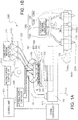
- Figs. 1A to 2B are diagrams showing a schematic configuration of a three-dimensionally formed object manufacturing apparatus according to an embodiment of the invention.
- the three-dimensionally formed object manufacturing apparatus includes two kinds of material supply portions (head bases). However, in each of Figs. 1A to 2B , only one kind of the material supply portions is shown, and the other kind of material supply portion is not shown.
- the material supply portion shown in Figs. 1A and 1B supplies a flowable composition (constituent material) including constituent material particles of a three-dimensionally formed object.
- the material supply portion shown in Figs. 2A and 2B supplies a flowable composition (support portion-forming material) including support portion-forming particles for forming a support portion which supports the three-dimensionally formed object during the formation of the three-dimensionally formed object.
- Each of the flowable composition including the constituent material particles and the flowable composition including the support portion-forming particles may or may not include a solvent and a binder.
- Three-dimensional forming described in this specification represents forming a so-called three-dimensionally formed object which also includes a planar formed object, that is, a so-called two-dimensionally formed object having a thickness.
- support includes supporting something from below or the side and, in some cases, also includes supporting something from above.
- a three-dimensionally formed object manufacturing apparatus 2000 (hereinafter, referred to as "manufacturing apparatus 2000") shown in Figs. 1A to 2B includes: a base 110; a stage 120 that is provided so as to move in X, Y, and Z directions shown in the drawing or to be driven in a rotating direction around a Z axis by a driving device 111 as a driving unit which is included in the base 110.
- the three-dimensionally formed object manufacturing apparatus 2000 includes a head base support portion 130.
- the base 110 is fixed to one end portion of the head base support portion 130.
- a head base 1100 in which plural head units 1400 are held is fixed to the other end portion of the head base support portion 130, in which each of the head units 1400 includes a constituent material ejecting portion that ejects the constituent material.
- the three-dimensionally formed object manufacturing apparatus 2000 includes a head base support portion 130'.
- the base 110 is fixed to one end portion of the head base support portion 130'.
- a head base 1100' in which plural head units 1400' are held is fixed to the other end portion of the head base support portion 130', in which each of the head units 1400' includes a support portion-forming material ejecting portion that ejects the constituent material.
- the head base 1100 and the head base 1100' are provided in parallel on an XY plane.
- the constituent material ejecting portion 1230 and the support portion-forming material ejecting portion 1230' have the same configuration, except that different materials (the constituent material and the support portion-forming material) are ejected.
- the invention is not limited to the above-described configuration.
- a heating portion 1700 is provided, and irradiation of heat energy thereof is controlled to be started or stopped by a heating portion controller 1710, which is connected to a control unit 400 described below, such that the entire region of the stage 120 can be heated.
- the three-dimensionally formed object 500 In order to form the three-dimensionally formed object 500, heat energy is irradiated (energy is imparted) by the heating portion 1700. In order to protect the three-dimensionally formed object 500 from heat generated from the stage 120, the three-dimensionally formed object 500 may be formed on a sample plate 121 having heat resistance. As the sample plate 121, for example, a ceramic plate is used. As a result, high heat resistance can be obtained, the reactivity between the sample plate and the constituent material of the three-dimensionally formed object to be sintered is low, and the deterioration of the three-dimensionally formed object 500 can be prevented. In Figs. 1A and 2A , for convenience of description, a three-layer structure including the layers 501, 502, and 503 is adopted. However, layers (in Figs. 1A and 2A , up to a layer 50n) may be formed until the three-dimensionally formed object 500 has a desired shape.
- each of the layers 501, 502, 503, and 50n includes: a support layer 300 that is formed of the support portion-forming material ejected from the support portion-forming material ejecting portion 1230'; and a constituent layer 310 (corresponding to a constituent region of the three-dimensionally formed object 500) that is formed of the constituent material ejected from the constituent material ejecting portion 1230.
- thermoforming plural pairs or sets of the constituent layers 310 and the support layers 300 the shape of a three-dimensionally formed object is completed.
- This three-dimensionally formed object can be sintered in a thermostatic chamber (heating portion) which is provided separately from the manufacturing apparatus 2000.
- Fig. 1B is an enlarged view showing a C portion which is the head base 1100 shown in Fig. 1A .
- the head base 1100 holds the plural head units 1400.
- one head unit 1400 is formed by the constituent material ejecting portion 1230, which is included in a constituent material supply device 1200, being held by a holding jig 1400a.
- the constituent material ejecting portion 1230 includes: an ejection nozzle 1230a; and an ejection driving portion 1230b that is controlled by a material supply controller 1500 to eject the constituent material through the ejection nozzle 1230a.
- Fig. 2B is an enlarged view showing a C' portion which is the head base 1100' shown in Fig. 2A .
- the head base 1100' holds the plural head units 1400'.
- One head unit 1400' is formed by the support portion-forming material ejecting portion 1230', which is included in a support portion-forming material supply device 1200', being held by a holding jig 1400a'.
- the support portion-forming material ejecting portion 1230' includes: an ejection nozzle 1230a'; and an ejection driving portion 1230b' that is controlled by the material supply controller 1500 to eject the support portion-forming material through the ejection nozzle 1230a'.
- the heating portion 1700 will be described as an energy irradiating portion which irradiates electromagnetic waves as heat energy.
- electromagnetic waves as the heat energy to be irradiated
- a supply material as a target can be efficiently irradiated with energy, and a high-quality three-dimensionally formed object can be formed.
- the intensity of irradiation energy can be easily controlled according to, for example, the kinds of materials to be ejected, and a three-dimensionally formed object having a desired quality can be obtained.
- the invention is not limited to the above-described configuration, and the layers may be heated using another method. It is needless to say that the invention is not limited to the configuration in which the layers are sintered by electromagnetic waves.
- the constituent material ejecting portion 1230 is connected to a constituent material supply unit 1210 through a supply tube 1220, the constituent material supply unit 1210 accommodating the constituent material and corresponding to each of the head units 1400 which are held in the head base 1100.
- a predetermined constituent material is supplied from the constituent material supply unit 1210 to the constituent material ejecting portion 1230.
- the constituent material supply unit 1210 includes constituent material accommodating portions 1210a, and a supply material including raw materials of the three-dimensionally formed object 500 (a paste-like constituent material including metal particles (constituent material particles)), which is formed using the manufacturing apparatus 2000 according to the embodiment, is accommodated in the constituent material accommodating portions 1210a.
- Each of the constituent material accommodating portions 1210a is connected to each of the constituent material ejecting portions 1230 through the supply tube 1220. In this way, by including each of the constituent material accommodating portions 1210a, the constituent material supply unit 1210 can supply different kinds of materials through the head base 1100.
- the support portion-forming material ejecting portion 1230' is connected to a support portion-forming material supply unit 1210' through a supply tube 1220', the support portion-forming material supply unit 1210' accommodating the support portion-forming material and corresponding to each of the head units 1400' which are held in the head base 1100'.
- a predetermined support portion-forming material is supplied from the support portion-forming material supply unit 1210' to the support portion-forming material ejecting portion 1230'.
- the support portion-forming material supply unit 1210' includes support portion-forming material accommodating portions 1210a', and a supply material including the support portion-forming material which forms the support portion during the formation of the three-dimensionally formed object 500 (a paste-like support portion-forming material including ceramic particles (support portion-forming particles)) is accommodated in the support portion-forming material accommodating portions 1210a'.
- a supply material including the support portion-forming material which forms the support portion during the formation of the three-dimensionally formed object 500 (a paste-like support portion-forming material including ceramic particles (support portion-forming particles)) is accommodated in the support portion-forming material accommodating portions 1210a'.
- Each of the support portion-forming material accommodating portions 1210a' is connected to one or more of the support portion-forming material ejecting portions 1230' through the supply tube 1220'. In this way, by including each of the support portion-forming material accommodating portions 1210a', the support portion-forming material supply unit 1210' can supply different kinds of materials through the head base 1100'.
- a slurry-like (or paste-like) mixed material including a single powder or a mixed powder, a solvent, and a binder
- the single powder include powders of magnesium (Mg), iron (Fe), cobalt (Co), chromium (Cr), aluminum (Al), titanium (Ti), copper (Cu), and nickel (Ni)
- the mixed powder include powders of alloys including one or more of the above-described metals (maraging steel, stainless steel, cobalt-chromium-molybdenum, titanium alloys, nickel alloys, aluminum alloys, cobalt alloys, and cobalt-chromium alloys).
- a general engineering plastic such as polyamide, polyacetal, polycarbonate, modified polyphenyl ether, polybutylene terephthalate, or polyethylene terephthalate can be used.
- an engineering plastic such as polysulfone, polyether sulfone, polyphenylene sulfide, polyarylate, polyimide, polyamide imide, polyether imide, or polyether ether ketone can be used.
- constituent material for example, a metal other than the above-described metals, a ceramic, or a resin can be used without any particular limitation.
- the solvent examples include: water; (poly)alkylene glycol monoalkyl ethers such as ethylene glycol monomethyl ether, ethylene glycol monoethyl ether, propylene glycol monomethyl ether, or propylene glycol monoethyl ether; acetates such as ethyl acetate, n-propyl acetate, isopropyl acetate, n-butyl acetate, or isobutyl acetate; aromatic hydrocarbons such as benzene, toluene, or xylene; ketones such as methyl ethyl ketone, acetone, methyl isobutyl ketone, ethyl-n-butyl ketone, diisopropyl ketone, or acetyl acetone; alcohols such as ethanol, propanol, or butanol; tetraalkylammonium acetates; sulfoxide solvents such as
- binder examples include: synthetic resins such as an acrylic resin, an epoxy resin, a silicone resin, or a cellulose resin; and thermoplastic resins such as polylactic acid (PLA), polyamide (PA), or polyphenylene sulfide (PPS).
- synthetic resins such as an acrylic resin, an epoxy resin, a silicone resin, or a cellulose resin
- thermoplastic resins such as polylactic acid (PLA), polyamide (PA), or polyphenylene sulfide (PPS).
- the support portion-forming material includes a ceramic.
- a slurry-like (or paste-like) mixed material can be used, the mixed material being obtained by kneading a mixed powder of a metal oxide, a metal alkoxide, a metal, and the like with a solvent and a thickener as a binder.
- the support portion-forming material is not particularly limited, and a metal or a resin other than ceramics described in the above-described examples of constituent material can be used.
- the manufacturing apparatus 2000 includes a control unit 400 which controls the stage 120, the constituent material ejecting portions 1230 included in the constituent material supply device 1200, the heating portion 1700, and the support portion-forming material ejecting portions 1230' included in the support portion-forming material supply device 1200' based on data for forming a three-dimensionally formed object which is output from a data output device (not shown) such as a personal computer.
- the control unit 400 includes a control portion (not shown) which controls the stage 120 and the constituent material ejecting portion 1230 to be driven and operate in cooperation with each other and controls the stage 120 and the support portion-forming material supply device 1200' to be driven and operate in cooperation with each other.
- stage 120 which is provided to be movable on the base 110
- signals for controlling, for example, the moving start and stop, a moving direction, a moving amount, and a moving speed of the stage 120 are generated by a stage controller 410, and the stage 120 is transported by the driving device 111 included in the base 110 and moves in the X, Y, and Z directions shown in the drawings.
- signals for controlling, for example, the amount of the material ejected through the ejection nozzles 1230a by the ejection driving portions 1230b included in the constituent material ejecting portions 1230 are generated by the material supply controller 1500, and a predetermined amount of the constituent material is ejected through the ejection nozzles 1230a based on the generated signals.
- signals for controlling, for example, the amount of the material ejected through the ejection nozzles 1230a' by the ejection driving portions 1230b' included in the support portion-forming material ejecting portions 1230' are generated by the material supply controller 1500, and a predetermined amount of the support portion-forming material is ejected through the ejection nozzles 1230a' based on the generated signals.
- a control signal is output from the control unit 400 to the heating portion controller 1710, and an output signal for irradiating electromagnetic waves is output from the heating portion controller 1710 to the heating portion 1700.
- the head unit 1400' has the same configuration as that of the head unit 1400, except that the support portion-forming material ejecting portions 1230' are disposed in the same configuration instead of the constituent material ejecting portions 1230. Therefore, the detailed configuration of the head unit 1400' will be described.
- Figs. 3 and 4 show examples of a state where the head units 1400, are held in the head base 1100 and a state where the constituent material ejecting portions 1230 are held in each of the head units 1400.
- Fig. 3 is a diagram showing the external appearance of the head base 1100 when seen from a direction D shown in Fig. 1B .
- Fig. 4 is a schematic cross-sectional view taken along line E-E' shown in Fig. 3 .
- the plural head units 1400 are held by a fixing unit (not shown).
- the head base 1100 of the manufacturing apparatus 2000 includes eight head units 1400 including, from below in the drawing, head units 1401 and 1402 on a first line, head units 1403 and 1404 on a second line, head units 1405 and 1406 on a third line, and head units 1407 and 1408 on a fourth line.
- the constituent material ejecting portions 1230 included in each of the head units 1401 to 1408 are connected to the constituent material supply unit 1210 through the ejection driving portions 1230b and the supply tubes 1220 and are held by the holding jigs 1400a.
- the constituent material ejecting portions 1230 eject a material M, which is the constituent material of the three-dimensionally formed object, to the sample plate 121, which is mounted on the stage 120, through the ejection nozzles 1230a.
- the head unit 1401 ejects the material M, for example, in the form of liquid drops
- the head unit 1402 ejects the material M, for example, in the form of a continuous body.
- the material M is ejected in the form of liquid drops.
- the ejection nozzles 1230a can supply the constituent material in the form of a continuous body.
- the landed material M forms landed portions 50.
- An aggregate of the landed portions 50 is formed as the constituent layer 310 (refer to Fig. 1A ) of the three-dimensionally formed object 500 formed on the sample plate 121.
- Figs. 5A to 7 are plan views (when seen from the D direction shown in Fig. 1B ) schematically showing a relationship between a disposition of the head units 1400 and a formed state of the landed portions 50.
- the material M is ejected through the ejection nozzles 1230a of the head units 1401 and 1402 and lands on the sample plate 121 to form landed portions 50a and 50b.
- the landed portions 50 are hatched in a plan view, and the constituent layer 310 of the first layer 501 formed on the top surface of the sample plate 121 will be described as an example.
- the material M is ejected through the constituent material ejecting portions 1230 included in the head units 1401 and 1402 on the first line from below in the drawing.
- the ejected material M forms the landed portions 50a and 50b.
- the sample plate 121 While continuously ejecting the material M through the constituent material ejecting portions 1230 of the head units 1401 and 1402, the sample plate 121 is moved in the Y (+) direction relative to the head base 1100 such that the forming start point q1 shown in Fig. 5B is positioned at a position corresponding to the head units 1403 and 1404 on the second line.
- the landed portions 50a and 50b extend while maintaining a width t ranging from the forming start point q1 to a position q2 after the relative movement of the sample plate 121.
- the material M is ejected from the head units 1403 and 1404 on the second line corresponding to the forming start point q1 and starts to form landed portions 50c and 50d.
- the landed portions 50c and 50d are started to be formed, and while continuously ejecting the material M through the constituent material ejecting portions 1230 of the head units 1401, 1402, 1403 and 1404, the sample plate 121 is moved in the Y (+) direction relative to the head base 1100 such that the forming start point q1 shown in Fig. 5C is positioned at a position corresponding to the head units 1405 and 1406 on the third line.
- the landed portions 50c and 50d extend while maintaining the width t ranging from the forming start point q1 to the position q2 after the relative movement of the sample plate 121.
- the landed portions 50a and 50b extend while maintaining the width t ranging from the forming start point q1 to a position q3 after the relative movement of the sample plate 121.
- the material M is ejected from the head units 1405 and 1406 on the third line corresponding to the forming start point q1 and starts to form landed portions 50e and 50f.
- the landed portions 50e and 50f are started to be formed, and while continuously ejecting the material M through the constituent material ejecting portions 1230 of the head units 1401, 1402, 1403, 1404, 1405 and 1406, the sample plate 121 is moved in the Y (+) direction relative to the head base 1100 such that the forming start point q1 shown in Fig. 6D is positioned at a position corresponding to the head units 1407 and 1408 on the fourth line.
- the landed portions 50e and 50f extend while maintaining the width t ranging from the forming start point q1 to the position q2 after the relative movement of the sample plate 121.
- the landed portions 50a and 50b extend while maintaining the width t ranging from the forming start point q1 to a position q4 after the relative movement of the sample plate 121, and the landed portions 50c and 50d extend while maintaining the width t ranging from the forming start point q1 to the position q3 after the relative movement of the sample plate 121.
- the material M is ejected from the head units 1407 and 1408 on the fourth line corresponding to the forming start point q1 and starts to form landed portions 50g and 50h.
- a position q5 is set as a forming end point (hereinafter, the position q5 will be referred to as "forming end point q5")
- the sample plate 121 is relatively moved until the head units 1401 and 1402 reach the forming end point q5 such that the landed portions 50g and 50h extend.
- the ejection of the material M through the constituent material ejecting portions 1230 of the head units 1401 and 1402 is stopped.
- the material M is ejected through the constituent material ejecting portions 1230 until the head units 1403, 1404, 1405, 1406, 1407, and 1408 reach the forming end point q5.
- the landed portions 50a, 50b, 50c, 50d, 50e, 50f, 50g, and 50h are formed in the region from the forming start point q1 to the forming end point q5 while maintaining the width t.
- the material M is ejected and supplied from the head units 1401, 1402, 1403, 1404, 1405, 1406, 1407, and 1408 in this order.
- a substantially rectangular aggregate of the landed portions 50 having a width T and a length J can be formed.
- the constituent layer 310 of the first layer 501 which is the aggregate of the landed portions 50 can be formed.
- the material M is selectively ejected and supplied through the constituent material ejecting portions 1230 included in the head units 1401, 1402, 1403, 1404, 1405, 1406, 1407, and 1408.
- the constituent layer 310 having a desired shape can be formed on the sample plate 121.
- the landed portions 50 having a desired shape can be formed in the region having the width T and the length J shown in Fig. 7 , and further the constituent layer 310 which is the aggregate of the landed portions 50 can be formed therein.
- a constituent material ejected and supplied from one unit or two or more units among the head units 1401, 1402, 1403, 1404, 1405, 1406, 1407, and 1408 may be different from a constituent material ejected and supplied from the other units. Accordingly, by using the manufacturing apparatus 2000 according to the embodiment, a three-dimensionally formed object formed of different materials can be formed.
- the support layer 300 can be formed using the same method as described above by ejecting the support portion-forming material through the support portion-forming material ejecting portions 1230' before, during or after the formation of the constituent layer 310.
- the layers 502, 503, ..., and 50n are formed by being laminated on the layer 501, the constituent layers 310 and the support layers 300 can be formed using the same method as described above.
- Figs. 8A and 8B are diagrams schematically showing other disposition examples of the head units 1400 disposed on the head base 1100.
- Fig. 8A shows a state where the plural head units 1400 are provided in parallel in the X axis direction in the head base 1100.
- Fig. 8B shows a state where the plural head units 1400 are provided in a lattice shape in the head base 1100.
- the number of head units disposed is not limited to that of each of the examples shown in Figs 8A and 8B .
- Figs. 9A to 9H are diagrams schematically showing an example of a process of manufacturing a three-dimensionally formed object which is performed using the manufacturing apparatus 2000.
- the layer is heated using the heating portion 1700 included in the manufacturing apparatus 2000.
- a sintered three-dimensionally formed object is manufactured.
- auxiliary lines are drawn in the Y direction and aligned in the Z direction such that the thicknesses of the support layer 300 and the constituent layer 310 can be easily recognized.
- the constituent layer 310 and the support layer 300 are formed in the first layer 501 by ejecting the constituent material through the constituent material ejecting portions 1230 and ejecting the support portion-forming material through the support portion-forming material ejecting portions 1230'.
- the support layer 300 is formed in regions of the layer excluding a region where the three-dimensionally formed object is formed (a region corresponding to the constituent layer 310).
- the first layer 501 is heated by the heating portion 1700 such that the constituent layer 310 is sintered and the support layer 300 is pre-sintered in the layer 501.
- the heating temperature of the heating portion 1700 is set as a temperature at which metal particles (constituent material particles) included in the constituent material are sintered and at which ceramic particles (support portion-forming particles) included in the support portion-forming material are pre-sintered.
- Pre-sintering represents that the constituent material particles are bonded to each other with a weak strength by reducing the sintered density to be lower than that during normal sintering, and examples of a pre-sintering method includes a method of desorbing a part of the particles from the material in advance and a method of oxidizing a part of the particles included in the material.
- the constituent layer 310 and the support layer 300 are formed in the second layer 502 by ejecting the constituent material through the constituent material ejecting portions 1230 and ejecting the support portion-forming material through the support portion-forming material ejecting portions 1230'.
- the second layer 502 is heated by the heating portion 1700.
- the constituent layer 310 and the support layer 300 are formed in the third layer 503.
- the third layer 503 is heated by the heating portion 1700.
- the constituent layer 310 and the support layer 300 are formed in the fourth layer 504.
- the fourth layer 504 is heated by the heating portion 1700.
- Fig. 10 is the flowchart showing the method of manufacturing a three-dimensionally formed object.
- Step S110 data of a three-dimensionally formed object is acquired in Step S110.
- data representing the shape of the three-dimensionally formed object is acquired from, for example, an application program which is performed by a personal computer.
- Step S120 data for each layer is created. Specifically, in the data representing the shape of the three-dimensionally formed object, bitmap data (cross-sectional data) is generated for each of cross-sections which are obtained by slicing the three-dimensionally formed object according to a forming resolution in the Z direction.
- bitmap data cross-sectional data
- a region where the three-dimensionally formed object is formed is distinguished from regions where the three-dimensionally formed object is not formed.
- Step S130 the constituent material is ejected (supplied) through the constituent material ejecting portions 1230 based on the data for forming the region where the three-dimensionally formed object is formed. As a result, the constituent layer 310 is formed.
- Step S140 the support portion-forming material is ejected (supplied) through the support portion-forming material ejecting portions 1230' based on the data for forming the regions where the three-dimensionally formed object is not formed.
- the support layer 300 is formed on the same layer as that on which the constituent layer 310 is formed in Step S130.
- Step S130 and Step S140 may be reversed, or Step S130 and Step S140 may be performed at the same time.
- Step S150 the layer on which the constituent layer 310 is formed in Step S130 and on which the support layer 300 is formed in Step S140 is irradiated (imparted with heat energy) with electromagnetic waves by the heating portion 1700.
- the constituent layer 310 is sintered, and the support layer 300 is pre-sintered.
- the constituent layer 310 is sintered, and the support layer 300 is pre-sintered.
- the support layer 300 is not necessarily pre-sintered.
- Step S160 whether or not the formation of the three-dimensionally formed object is finished is determined based on the bitmap data corresponding to each of the layers which are generated in Step S120, and Steps S130 to S160 are repeated until the formation of the three-dimensionally formed object is finished.
- Step S170 the three-dimensionally formed object is extracted (the regions corresponding to the support layer 300, which are the regions where the three-dimensionally formed object is not formed, are removed from the layer to obtain the region corresponding to the constituent layer 310 which is the region where the three-dimensionally formed object is formed; that is, the three-dimensionally formed object is cleaned).
- the method of manufacturing a three-dimensionally formed object according to the example ends.
- Figs. 11A to 11E are diagrams schematically showing another example of a process of manufacturing a three-dimensionally formed object which is performed using the manufacturing apparatus 2000.
- the method of manufacturing a three-dimensionally formed object according to the example after the formation of a shape of a three-dimensionally formed object is finished by ejecting the constituent material and the support portion-forming material through the constituent material ejecting portions 1230 and the support portion-forming material ejecting portions 1230', the shaped product of the three-dimensionally formed object is heated in a thermostatic chamber (not shown), which is provided separately from the manufacturing apparatus 2000, without using the heating portion 1700 included in the manufacturing apparatus 2000.
- a sintered three-dimensionally formed object is manufactured.
- auxiliary lines are drawn such that the thicknesses of the support layer 300 and the constituent layer 310 can be easily recognized in the Z direction.
- the constituent layer 310 and the support layer 300 are formed in the first layer 501 by ejecting the constituent material through the constituent material ejecting portions 1230 and ejecting the support portion-forming material through the support portion-forming material ejecting portions 1230'.
- the support layer 300 is formed in regions of the layer excluding a region where the three-dimensionally formed object is formed (a region corresponding to the constituent layer 310).
- the constituent layer 310 and the support layer 300 are formed in the second layer 502 by ejecting the constituent material through the constituent material ejecting portions 1230 and ejecting the support portion-forming material through the support portion-forming material ejecting portions 1230'.
- the shaped product of the three-dimensionally formed object is heated in the thermostatic chamber (not shown) such that the constituent layer 310 is sintered and the support layer 300 is pre-sintered in the shaped product of the three-dimensionally formed object.
- the heating temperature in the thermostatic chamber is set as a temperature at which metal particles (constituent material particles) included in the constituent material are sintered and at which ceramic particles (support portion-forming particles) included in the support portion-forming material are pre-sintered.
- Fig. 12 is the flowchart showing the method of manufacturing a three-dimensionally formed object.
- Steps S110 to S140 and Step S170 of Fig. 12 Since operations in Steps S110 to S140 and Step S170 of Fig. 12 are the same as those in Steps S110 to S140 and Step S170 of Fig. 10 , the description thereof will not be repeated.
- Step S160 in the method of manufacturing a three-dimensionally formed object according to the example, the process proceeds to Step S160 after the completion of Step S140.
- Step S160 whether or not the formation of the shaped product of the three-dimensionally formed object is finished is determined based on the bitmap data corresponding to each of the layers which are generated in Step S120, and Steps S130 to S160 are repeated until the formation of the shaped product of the three-dimensionally formed object is finished. Once the formation of the shaped product of the three-dimensionally formed object is finished, the process proceeds to Step S165.
- Step S165 the shaped product of the three-dimensionally formed object, which is formed by repeating the Steps S130 to S160, is heated in the thermostatic chamber (not shown) such that the constituent layer 310 is sintered and the support layer 300 is pre-sintered.
- the constituent layer 310 is sintered, and the support layer 300 is pre-sintered.
- the support layer 300 is not necessarily pre-sintered.
- the method of manufacturing a three-dimensionally formed object includes: a layer forming step (Steps S130 and S140) of forming a layer using a flowable composition (constituent material) including constituent material particles of a three-dimensionally formed object and a flowable composition (support portion-forming material) including support portion-forming particles for forming a support portion which supports the three-dimensionally formed object during the formation of the three-dimensionally formed object; and an energy imparting step (Steps S150 and Steps S165) of imparting energy to the constituent material particles and the support portion-forming particles.
- a layer forming step (Steps S130 and S140) of forming a layer using a flowable composition (constituent material) including constituent material particles of a three-dimensionally formed object and a flowable composition (support portion-forming material) including support portion-forming particles for forming a support portion which supports the three-dimensionally formed object during the formation of the three-dimensionally formed object.
- the energy is imparted such that a temperature of the constituent material particles and a temperature of the support portion-forming particles are equal to or higher than a sintering temperature of the constituent material particles and are lower than a sintering temperature of the support portion-forming particles.
- the sintering of the support portion can be prevented while sintering the constituent material of the three-dimensionally formed object. Therefore, when an extracting operation of extracting the three-dimensionally formed object, a forming operation after the extracting operation, or the like is performed, an increase in load caused by the sintering of other regions of the layer excluding the region corresponding to the three-dimensionally formed object can be prevented. Accordingly, the number of steps performed after a three-dimensionally formed object is formed can be reduced.
- the three-dimensionally formed object manufacturing apparatus includes: an ejecting portion (constituent material ejecting portion 1230) that ejects a flowable composition (constituent material) including constituent material particles of a three-dimensionally formed object; an ejecting portion (support portion-forming material ejecting portion 1230') that ejects a flowable composition (support portion-forming material) including support portion-forming particles for forming a support portion which supports the three-dimensionally formed object during the formation of the three-dimensionally formed object; a control portion (control unit 400) that controls the three-dimensionally formed object manufacturing apparatus to form a layer using the flowable composition including the constituent material particles and the flowable composition including the support portion-forming particles; and an energy imparting portion (heating portion 1700) that imparts energy to the constituent material particles and the support portion-forming particles.
- an ejecting portion that ejects a flowable composition (constituent material) including constituent material particles of a three-dimensionally formed object
- the energy imparting portion is adjusted to impart the energy such that a temperature of the constituent material particles and a temperature of the support portion-forming particles are equal to or higher than a sintering temperature of the constituent material particles and are lower than a sintering temperature of the support portion-forming particles.
- the sintering of the support portion can be prevented while sintering the constituent material of the three-dimensionally formed object. Therefore, when an extracting operation of extracting the three-dimensionally formed object, a forming operation after the extracting operation, or the like is performed, an increase in load caused by the sintering of other regions of the layer excluding the region corresponding to the three-dimensionally formed object can be prevented. Accordingly, the number of steps performed after a three-dimensionally formed object is formed can be reduced.
- the flowable composition including the constituent material particles and the flowable composition including the support portion-forming particles are ejected in the form of liquid drops to form the layer. Therefore, using a simple method of forming the layer, the three-dimensionally formed object can be formed.
- the method of manufacturing a three-dimensionally formed object according to any one of the examples includes a laminating step (Steps S130 to S160) of repeating the layer forming step (Steps S130 and S140). Therefore, by repeating the layer forming step, the three-dimensionally formed object can be simply formed.
- the energy imparting step (Step S165) is performed after completion of the laminating step (Steps S130 to Steps S160). Therefore, after the shape of the three-dimensionally formed object is formed, the three-dimensionally formed object can be sintered through one step.
- the method of manufacturing a three-dimensionally formed object according to any one of the examples further includes a cleaning step (Step S170) of cleaning the three-dimensionally formed object after the energy imparting step (Steps S150 and S165). Therefore, a clean three-dimensionally formed object can be obtained.
- “Cleaning” represents removing impurities such as support portion-forming particles attached to the periphery of the sintered three-dimensionally formed object.
- the method of manufacturing a three-dimensionally formed object according to any one of the examples may further include: a pre-energy imparting step of imparting energy having a lower intensity than the energy of the energy imparting step to the constituent material particles and the support portion-forming particles; and a removal step of removing the support portion-forming particles, in which the pre-energy imparting step and the removal step are performed before the energy imparting step (Steps S150 and S165).
- the pre-energy imparting step and the removal step are added between Step S140 and Step 150.
- the pre-energy imparting step and the removal step are added such that the pre-energy imparting step and the removal step are performed before Step S165. Therefore, by performing the pre-energy imparting step as described above, the shape of the three-dimensionally formed object can be verified before the energy imparting step, and deformation in the shape of the three-dimensionally formed object before the energy imparting step can be prevented.
- the pre-energy imparting step represents that the three-dimensionally formed object is heated at a lower heating temperature than that in the energy imparting step, and represents that, for example, the constituent material particles are sintered (pre-sintered) at a lower intensity than that in the energy imparting step.
- Figs. 13A to 13E are diagrams schematically showing a process of manufacturing a three-dimensionally formed object according to an example of the invention, the process including the pre-energy imparting step and the removal step.
- Fig. 13A shows the three-dimensionally formed object 500 before being sintered (before the energy imparting step).
- Fig. 13B shows a state where the constituent layer 310 is pre-sintered (a state where the support layer 300 is neither sintered nor pre-sintered) by performing the pre-energy imparting step in the state of Fig. 13A.
- FIG. 13C shows a state where the support portion-forming particles are removed from the periphery of the three-dimensionally formed object 500 (a state where the shape of the three-dimensionally formed object can be verified) by performing the removal step in the state of Fig. 13B.
- Fig. 13E shows a state where the three-dimensionally formed object 500 is sintered in, for example, the thermostatic chamber (not shown) by performing the energy imparting step in the state of Fig. 13C .
- the energy in the energy imparting step (Steps S150 and S165), the energy may be imparted in a state where the three-dimensionally formed object is supported by particles which are not sintered during the energy imparting in the energy imparting step (a state where the three-dimensionally formed object 500 is supported by the support layer 300).
- the energy is imparted in a state where the three-dimensionally formed object is supported by particles which are not sintered during the energy imparting in the energy imparting step.
- the deformation of the shape of the three-dimensionally formed object can be prevented in the energy imparting step while preventing deformation in the shape of the three-dimensionally formed object before the energy imparting step.
- Particles which are not sintered during the energy imparting in the energy imparting step may be the same as or different from the support portion-forming particles. In a case where the particles are different from the support portion-forming particles, it is preferable that a sintering temperature of the particles is higher than that of the support portion-forming particles.
- the energy imparting step (Steps S150 and S165)
- the same intensity of energy is imparted to the constituent material particles and the support portion-forming particles (the constituent material particles and the support portion-forming particles are irradiated with electromagnetic waves by the heating portion 1700 in Step S150, and the constituent material particles and the support portion-forming particles are collectively heated in the thermostatic chamber (not shown) in Step S 165). Therefore, the energy imparting step can be simply performed.
- different intensities of energy may be imparted to the constituent material particles and the support portion-forming particles.
- different intensities of energy By imparting different intensities of energy, excessive sintering of other regions of the layer excluding the region corresponding to the three-dimensionally formed object can be effectively prevented, and when an extracting operation of extracting the three-dimensionally formed object, a forming operation after the extracting operation, or the like is performed, an increase in load can be prevented.
- the constituent material particles include at least one component of aluminum, titanium, iron, copper, magnesium, stainless steel, or maraging steel and that the support portion-forming particles include at least one component of silica, alumina, titanium oxide, or zirconium oxide.
- the sintered state of the constituent material particles and the support portion-forming particles in the energy imparting step can be easily controlled from a high sintered density to a low sintered density, for example, a non-sintered state. Therefore, while securing the strength of the three-dimensionally formed object, an increase in the load of an extracting operation of extracting the three-dimensionally formed object, a forming operation after the extracting operation, or the like can be prevented.
Abstract
Description
- The present invention relates to a method of manufacturing a three-dimensionally formed object and a three-dimensionally formed object manufacturing apparatus.
- In the related art, various methods of manufacturing a three-dimensionally formed object have been disclosed. Among these, a method of forming a three-dimensionally formed object using a flowable composition is disclosed.
- For example,
JP-A-2008-184622 - However, in a case where the three-dimensionally formed object is manufactured while sintering or melting the region corresponding to the three-dimensionally formed object, other regions of the layer excluding the region corresponding to the three-dimensionally formed object are sintered or melted due to heat generated during the sintering or melting of the region corresponding to the three-dimensionally formed object. Therefore, when an extracting operation of extracting the three-dimensionally formed object, a forming operation after the extracting operation, or the like is performed, the load may be high. That is, in the method of manufacturing a three-dimensionally formed object in the related art, the number of steps performed after a three-dimensionally formed object is manufactured is not sufficiently reduced.
- An advantage of some aspects of the invention is to reduce the number of steps performed after a three-dimensionally formed object is formed.
- A first aspect of the invention is directed to a method of manufacturing a three-dimensionally formed object including: forming a layer using a flowable composition including constituent material particles of a three-dimensionally formed object and a flowable composition including support portion-forming particles for forming a support portion which supports the three-dimensionally formed object during the formation of the three-dimensionally formed object; and imparting energy to the constituent material particles and the support portion-forming particles, in which in the imparting of the energy, the energy is imparted such that a temperature of the constituent material particles and a temperature of the support portion-forming particles are equal to or higher than a sintering temperature of the constituent material particles and are lower than a sintering temperature of the support portion-forming particles.
- According to this aspect, the energy is imparted such that the temperature of the constituent material particles and the temperature of the support portion-forming particles are equal to or higher than the sintering temperature of the constituent material particles and are lower than the sintering temperature of the support portion-forming particles. Therefore, the sintering of the support portion can be prevented while sintering the constituent material of the three-dimensionally formed object. Therefore, when an extracting operation of extracting the three-dimensionally formed object, a forming operation after the extracting operation, or the like is performed, an increase in load caused by the sintering of other regions of the layer excluding the region corresponding to the three-dimensionally formed object can be prevented. Accordingly, the number of steps performed after a three-dimensionally formed object is formed can be reduced.
- A second aspect of the invention is directed to the method of manufacturing a three-dimensionally formed object according to the first aspect, in which in the forming of the layer, the flowable composition including the constituent material particles and the flowable composition including the support portion-forming particles are ejected in the form of liquid drops to form the layer.
- According to this aspect, the flowable composition including the constituent material particles and the flowable composition including the support portion-forming particles are ejected in the form of liquid drops to form the layer. Therefore, by forming the layer, the three-dimensionally formed object can be simply formed.
- A third aspect of the invention is directed to the method of manufacturing a three-dimensionally formed object according to the first or second aspect, in which the method further includes repeating the forming of the layer.
- According to this aspect, the method of manufacturing a three-dimensionally formed object includes the repeating of the forming of the layer. Therefore, by repeating the forming of the layer, the three-dimensionally formed object can be simply formed.
- A fourth aspect of the invention is directed to the method of manufacturing a three-dimensionally formed object according to anyone of the first to the third aspects, in which the imparting of the energy is performed after completion of the repeating of the forming of the layer.
- According to this aspect, the imparting of the energy is performed after completion of the repeating of the forming of the layer. That is, after the shape of the three-dimensionally formed object is formed, the three-dimensionally formed object can be sintered through one step.
- A fifth aspect of the invention is directed to the method of manufacturing a three-dimensionally formed object according to any one of the first to fourth aspects, in which the method further includes cleaning the three-dimensionally formed object after the imparting of the energy.
- According to this aspect, the method of manufacturing a three-dimensionally formed object includes cleaning the three-dimensionally formed object after the imparting of the energy. Therefore, a clean three-dimensionally formed object can be obtained.
- "Cleaning" represents removing impurities such as support portion-forming particles attached to the periphery of the sintered three-dimensionally formed object.
- A sixth aspect of the invention is directed to the method of manufacturing a three-dimensionally formed object according to any one of the first to fifth aspects, in which the method further includes: pre-imparting energy having a lower intensity than the energy of the imparting of the energy to the constituent material particles and the support portion-forming particles; and removing the support portion-forming particles, in which the pre-imparting of the energy and the removing of the support portion-forming particles are performed before the imparting of the energy.
- According to this aspect, the method of manufacturing a three-dimensionally formed object further includes: pre-imparting energy having a lower intensity than the energy of the imparting of the energy to the constituent material particles and the support portion-forming particles; and removing the support portion-forming particles, in which the pre-imparting of the energy and the removing of the support portion-forming particles are performed before the imparting of the energy. Therefore, the shape of the three-dimensionally formed object can be verified before the imparting of the energy, and deformation in the shape of the three-dimensionally formed object before the imparting of the energy can be prevented.
- "The pre-imparting of the energy" represents the three-dimensionally formed object is heated at a lower heating temperature than that in the imparting of the energy, and represents that, for example, the constituent material particles are sintered (pre-sintered) at a lower intensity than than in the imparting of the energy.
- A seventh aspect of the invention is directed to the method of manufacturing a three-dimensionally formed object according to the sixth aspect, in which in the imparting of the energy, the energy is imparted in a state where the three-dimensionally formed object is supported by particles which are not sintered during the energy imparting in the imparting of the energy.
- According to this aspect, in the imparting of the energy, the energy is imparted in a state where the three-dimensionally formed object is supported by particles which are not sintered during the energy imparting in the imparting of the energy. Therefore, the shape of the three-dimensionally formed object can be modified in the imparting of the energy while preventing deformation in the shape of the three-dimensionally formed object before the imparting of the energy.
- "Particles which are not sintered during the energy imparting in the imparting of the energy" may be the same as or different from the support portion-forming particles. In a case where the particles are different from the support portion-forming particles, it is preferable that a sintering temperature of the particles is higher than that of the support portion-forming particles.
- An eighth aspect of the invention is directed to the method of manufacturing a three-dimensionally formed object according to anyone of the first to seventh aspects, in which in the imparting of the energy, the same intensity of energy is imparted to the constituent material particles and the support portion-forming particles.
- According to this aspect, the same intensity of energy is imparted to the constituent material particles and the support portion-forming particles. Therefore, the imparting of the energy can be simply performed.
- A ninth aspect of the invention is directed to the method of manufacturing a three-dimensionally formed object according to any one of the first to seventh aspects, in which in the imparting of the energy, different intensities of energy are imparted to the constituent material particles and the support portion-forming particles.
- According to this aspect, different intensities of energy are imparted to the constituent material particles and the support portion-forming particles. Therefore, excessive sintering of other regions of the layer excluding the region corresponding to the three-dimensionally formed object can be effectively prevented, and when an extracting operation of extracting the three-dimensionally formed object, a forming operation after the extracting operation, or the like is performed, an increase in load can be prevented.
- A tenth aspect of the invention is directed to the method of manufacturing a three-dimensionally formed object according to any one of the first to ninth aspects, in which the constituent material particles include at least one component of aluminum, titanium, iron, copper, magnesium, stainless steel, or maraging steel, and the support portion-forming particles include at least one component of silica, alumina, titanium oxide, or zirconium oxide.
- According to this aspect, the sintered state of the constituent material particles and the support portion-forming particles in the imparting of the energy can be easily controlled from a high sintered density to a low sintered density, for example, a non-sintered state. Therefore, while securing the strength of the three-dimensionally formed object, an increase in the load of an extracting operation of extracting the three-dimensionally formed object, a forming operation after the extracting operation, or the like can be prevented.
- An eleventh aspect of the invention is directed to a three-dimensionally formed object manufacturing apparatus including: an ejecting portion that ejects a flowable composition including constituent material particles of a three-dimensionally formed object; an ejecting portion that ejects a flowable composition including support portion-forming particles for forming a support portion which supports the three-dimensionally formed object during the formation of the three-dimensionally formed object; a control portion that controls the three-dimensionally formed object manufacturing apparatus to form a layer using the flowable composition including the constituent material particles and the flowable composition including the support portion-forming particles; and an energy imparting portion that imparts energy to the constituent material particles and the support portion-forming particles, in which the energy imparting portion is adjusted to impart the energy such that a temperature of the constituent material particles and a temperature of the support portion-forming particles are equal to or higher than a sintering temperature of the constituent material particles and are lower than a sintering temperature of the support portion-forming particles.
- According to this aspect, the energy is imparted such that the temperature of the constituent material particles and the temperature of the support portion-forming particles are equal to or higher than the sintering temperature of the constituent material particles and are lower than the sintering temperature of the support portion-forming particles. Therefore, the sintering of the support portion can be prevented while sintering the constituent material of the three-dimensionally formed object. Therefore, when an extracting operation of extracting the three-dimensionally formed object, a forming operation after the extracting operation, or the like is performed, an increase in load caused by the sintering of other regions of the layer excluding the region corresponding to the three-dimensionally formed object can be prevented. Accordingly, the number of steps performed after a three-dimensionally formed object is formed can be reduced.
- Embodiments of the invention will now be described by way of example only with reference to the accompanying drawings, wherein like numbers reference like elements.
-
Fig. 1A is a diagram showing a schematic configuration of a three-dimensionally formed object manufacturing apparatus according to an embodiment of the invention, andFig. 1B is an enlarged view showing a C portion shown inFig. 1A . -
Fig. 2A is a diagram showing a schematic configuration of the three-dimensionally formed object manufacturing apparatus according to the embodiment of the invention, andFig. 2B is an enlarged view showing a C' portion shown inFig. 2A . -
Fig. 3 is a diagram showing the external appearance of a head base according to the embodiment of the invention when seen from a D direction shown inFig. 1B . -
Fig. 4 is a cross-sectional view taken along line E-E' shown inFig. 3 . -
Figs. 5A to 5C are plan views schematically showing a relationship between a disposition of head units according to the embodiment of the invention and a formed state of landed portions. -
Figs. 6D and 6E are plan views schematically showing a relationship between a disposition of head units according to the embodiment of the invention and a formed state of landed portions. -
Fig. 7 is a plan view schematically showing a relationship between a disposition of head units according to the embodiment of the invention and a formed state of landed portions. -
Figs. 8A and 8B are diagrams schematically showing other disposition examples of head units disposed on the head base. -
Figs. 9A to 9H are diagrams schematically showing a process of manufacturing a three-dimensionally formed object according to an example of the invention. -
Fig. 10 is a flowchart showing the method of manufacturing a three-dimensionally formed object according to the example of the invention. -
Figs. 11A to 11E are diagrams schematically showing a process of manufacturing a three-dimensionally formed object according to an example of the invention. -
Fig. 12 is a flowchart showing the method of manufacturing a three-dimensionally formed object according to the example of the invention. -
Figs. 13A to 13E are diagrams schematically showing a process of manufacturing a three-dimensionally formed object according to an example of the invention. - Hereinafter, embodiments of the invention will be described with reference to the drawings.
-
Figs. 1A to 2B are diagrams showing a schematic configuration of a three-dimensionally formed object manufacturing apparatus according to an embodiment of the invention. - Here, the three-dimensionally formed object manufacturing apparatus according to the embodiment includes two kinds of material supply portions (head bases). However, in each of
Figs. 1A to 2B , only one kind of the material supply portions is shown, and the other kind of material supply portion is not shown. In addition, the material supply portion shown inFigs. 1A and 1B supplies a flowable composition (constituent material) including constituent material particles of a three-dimensionally formed object. The material supply portion shown inFigs. 2A and 2B supplies a flowable composition (support portion-forming material) including support portion-forming particles for forming a support portion which supports the three-dimensionally formed object during the formation of the three-dimensionally formed object. Each of the flowable composition including the constituent material particles and the flowable composition including the support portion-forming particles may or may not include a solvent and a binder. - "Three-dimensional forming" described in this specification represents forming a so-called three-dimensionally formed object which also includes a planar formed object, that is, a so-called two-dimensionally formed object having a thickness. In addition, the meaning of "support" includes supporting something from below or the side and, in some cases, also includes supporting something from above.
- A three-dimensionally formed object manufacturing apparatus 2000 (hereinafter, referred to as "
manufacturing apparatus 2000") shown inFigs. 1A to 2B includes: a base 110; astage 120 that is provided so as to move in X, Y, and Z directions shown in the drawing or to be driven in a rotating direction around a Z axis by adriving device 111 as a driving unit which is included in thebase 110. - As shown in
Figs. 1A and 1B , the three-dimensionally formedobject manufacturing apparatus 2000 includes a headbase support portion 130. Thebase 110 is fixed to one end portion of the headbase support portion 130. Ahead base 1100 in whichplural head units 1400 are held is fixed to the other end portion of the headbase support portion 130, in which each of thehead units 1400 includes a constituent material ejecting portion that ejects the constituent material. - In addition, as shown in
Figs. 2A and 2B , the three-dimensionally formedobject manufacturing apparatus 2000 includes a head base support portion 130'. Thebase 110 is fixed to one end portion of the head base support portion 130'. A head base 1100' in which plural head units 1400' are held is fixed to the other end portion of the head base support portion 130', in which each of the head units 1400' includes a support portion-forming material ejecting portion that ejects the constituent material. - Here, the
head base 1100 and the head base 1100' are provided in parallel on an XY plane. - The constituent
material ejecting portion 1230 and the support portion-forming material ejecting portion 1230' have the same configuration, except that different materials (the constituent material and the support portion-forming material) are ejected. However, the invention is not limited to the above-described configuration. - In the process of forming a three-dimensionally formed
object 500,layers stage 120. In addition, in a region facing thestage 120, aheating portion 1700 is provided, and irradiation of heat energy thereof is controlled to be started or stopped by aheating portion controller 1710, which is connected to acontrol unit 400 described below, such that the entire region of thestage 120 can be heated. - In order to form the three-dimensionally formed
object 500, heat energy is irradiated (energy is imparted) by theheating portion 1700. In order to protect the three-dimensionally formedobject 500 from heat generated from thestage 120, the three-dimensionally formedobject 500 may be formed on asample plate 121 having heat resistance. As thesample plate 121, for example, a ceramic plate is used. As a result, high heat resistance can be obtained, the reactivity between the sample plate and the constituent material of the three-dimensionally formed object to be sintered is low, and the deterioration of the three-dimensionally formedobject 500 can be prevented. InFigs. 1A and2A , for convenience of description, a three-layer structure including thelayers Figs. 1A and2A , up to alayer 50n) may be formed until the three-dimensionally formedobject 500 has a desired shape. - Here, each of the
layers support layer 300 that is formed of the support portion-forming material ejected from the support portion-forming material ejecting portion 1230'; and a constituent layer 310 (corresponding to a constituent region of the three-dimensionally formed object 500) that is formed of the constituent material ejected from the constituentmaterial ejecting portion 1230. Once a single layer is formed using the constituent material ejected from the constituentmaterial ejecting portion 1230 and the support portion-forming material ejected from the support portion-forming material ejecting portion 1230', the layer can be sintered by theheating portion 1700 irradiating the entire region of the layer with heat energy. Further, by forming plural pairs or sets of theconstituent layers 310 and the support layers 300, the shape of a three-dimensionally formed object is completed. This three-dimensionally formed object can be sintered in a thermostatic chamber (heating portion) which is provided separately from themanufacturing apparatus 2000. -
Fig. 1B is an enlarged view showing a C portion which is thehead base 1100 shown inFig. 1A . As shown inFig. 1B , thehead base 1100 holds theplural head units 1400. Although described below in detail, onehead unit 1400 is formed by the constituentmaterial ejecting portion 1230, which is included in a constituentmaterial supply device 1200, being held by a holdingjig 1400a. The constituentmaterial ejecting portion 1230 includes: anejection nozzle 1230a; and anejection driving portion 1230b that is controlled by amaterial supply controller 1500 to eject the constituent material through theejection nozzle 1230a. -
Fig. 2B is an enlarged view showing a C' portion which is the head base 1100' shown inFig. 2A . As shown inFig. 2B , the head base 1100' holds the plural head units 1400'. One head unit 1400' is formed by the support portion-forming material ejecting portion 1230', which is included in a support portion-forming material supply device 1200', being held by a holdingjig 1400a'. The support portion-forming material ejecting portion 1230' includes: anejection nozzle 1230a'; and anejection driving portion 1230b' that is controlled by thematerial supply controller 1500 to eject the support portion-forming material through theejection nozzle 1230a'. - In the embodiment, the
heating portion 1700 will be described as an energy irradiating portion which irradiates electromagnetic waves as heat energy. By using electromagnetic waves as the heat energy to be irradiated, a supply material as a target can be efficiently irradiated with energy, and a high-quality three-dimensionally formed object can be formed. In addition, for example, the intensity of irradiation energy (power, scanning rate) can be easily controlled according to, for example, the kinds of materials to be ejected, and a three-dimensionally formed object having a desired quality can be obtained. However, the invention is not limited to the above-described configuration, and the layers may be heated using another method. It is needless to say that the invention is not limited to the configuration in which the layers are sintered by electromagnetic waves. - As shown in
Figs. 1A and 1B , the constituentmaterial ejecting portion 1230 is connected to a constituentmaterial supply unit 1210 through asupply tube 1220, the constituentmaterial supply unit 1210 accommodating the constituent material and corresponding to each of thehead units 1400 which are held in thehead base 1100. A predetermined constituent material is supplied from the constituentmaterial supply unit 1210 to the constituentmaterial ejecting portion 1230. The constituentmaterial supply unit 1210 includes constituent materialaccommodating portions 1210a, and a supply material including raw materials of the three-dimensionally formed object 500 (a paste-like constituent material including metal particles (constituent material particles)), which is formed using themanufacturing apparatus 2000 according to the embodiment, is accommodated in the constituent materialaccommodating portions 1210a. Each of the constituent materialaccommodating portions 1210a is connected to each of the constituentmaterial ejecting portions 1230 through thesupply tube 1220. In this way, by including each of the constituent materialaccommodating portions 1210a, the constituentmaterial supply unit 1210 can supply different kinds of materials through thehead base 1100. - As shown in
Figs. 2A and 2B , the support portion-forming material ejecting portion 1230' is connected to a support portion-forming material supply unit 1210' through a supply tube 1220', the support portion-forming material supply unit 1210' accommodating the support portion-forming material and corresponding to each of the head units 1400' which are held in the head base 1100'. A predetermined support portion-forming material is supplied from the support portion-forming material supply unit 1210' to the support portion-forming material ejecting portion 1230'. The support portion-forming material supply unit 1210' includes support portion-formingmaterial accommodating portions 1210a', and a supply material including the support portion-forming material which forms the support portion during the formation of the three-dimensionally formed object 500 (a paste-like support portion-forming material including ceramic particles (support portion-forming particles)) is accommodated in the support portion-formingmaterial accommodating portions 1210a'. Each of the support portion-formingmaterial accommodating portions 1210a' is connected to one or more of the support portion-forming material ejecting portions 1230' through the supply tube 1220'. In this way, by including each of the support portion-formingmaterial accommodating portions 1210a', the support portion-forming material supply unit 1210' can supply different kinds of materials through the head base 1100'. - As the constituent material, for example, a slurry-like (or paste-like) mixed material including a single powder or a mixed powder, a solvent, and a binder can be used, in which examples of the single powder include powders of magnesium (Mg), iron (Fe), cobalt (Co), chromium (Cr), aluminum (Al), titanium (Ti), copper (Cu), and nickel (Ni), and examples of the mixed powder include powders of alloys including one or more of the above-described metals (maraging steel, stainless steel, cobalt-chromium-molybdenum, titanium alloys, nickel alloys, aluminum alloys, cobalt alloys, and cobalt-chromium alloys).
- In addition, a general engineering plastic such as polyamide, polyacetal, polycarbonate, modified polyphenyl ether, polybutylene terephthalate, or polyethylene terephthalate can be used. Further, an engineering plastic such as polysulfone, polyether sulfone, polyphenylene sulfide, polyarylate, polyimide, polyamide imide, polyether imide, or polyether ether ketone can be used.
- In this way, as the constituent material, for example, a metal other than the above-described metals, a ceramic, or a resin can be used without any particular limitation.
- Examples of the solvent include: water; (poly)alkylene glycol monoalkyl ethers such as ethylene glycol monomethyl ether, ethylene glycol monoethyl ether, propylene glycol monomethyl ether, or propylene glycol monoethyl ether; acetates such as ethyl acetate, n-propyl acetate, isopropyl acetate, n-butyl acetate, or isobutyl acetate; aromatic hydrocarbons such as benzene, toluene, or xylene; ketones such as methyl ethyl ketone, acetone, methyl isobutyl ketone, ethyl-n-butyl ketone, diisopropyl ketone, or acetyl acetone; alcohols such as ethanol, propanol, or butanol; tetraalkylammonium acetates; sulfoxide solvents such as dimethyl sulfoxide or diethyl sulfoxide; pyridine solvents such as pyridine, γ-picoline, or 2,6-lutidine; and ionic liquids of tetraalkylammonium acetates (for example, tetrabutylammonium acetate). One kind or a combination of two or more kinds selected from the above examples can be used.
- Examples of the binder include: synthetic resins such as an acrylic resin, an epoxy resin, a silicone resin, or a cellulose resin; and thermoplastic resins such as polylactic acid (PLA), polyamide (PA), or polyphenylene sulfide (PPS).
- In the embodiment, the support portion-forming material includes a ceramic. As the support portion-forming material, for example, a slurry-like (or paste-like) mixed material can be used, the mixed material being obtained by kneading a mixed powder of a metal oxide, a metal alkoxide, a metal, and the like with a solvent and a thickener as a binder.
- However, the support portion-forming material is not particularly limited, and a metal or a resin other than ceramics described in the above-described examples of constituent material can be used.
- The
manufacturing apparatus 2000 includes acontrol unit 400 which controls thestage 120, the constituentmaterial ejecting portions 1230 included in the constituentmaterial supply device 1200, theheating portion 1700, and the support portion-forming material ejecting portions 1230' included in the support portion-forming material supply device 1200' based on data for forming a three-dimensionally formed object which is output from a data output device (not shown) such as a personal computer. Thecontrol unit 400 includes a control portion (not shown) which controls thestage 120 and the constituentmaterial ejecting portion 1230 to be driven and operate in cooperation with each other and controls thestage 120 and the support portion-forming material supply device 1200' to be driven and operate in cooperation with each other. - Regarding the
stage 120 which is provided to be movable on thebase 110, based on control signals output from thecontrol unit 400, signals for controlling, for example, the moving start and stop, a moving direction, a moving amount, and a moving speed of thestage 120 are generated by astage controller 410, and thestage 120 is transported by the drivingdevice 111 included in thebase 110 and moves in the X, Y, and Z directions shown in the drawings. Regarding the constituentmaterial ejecting portions 1230 included in thehead units 1400, based on control signals output from thecontrol unit 400, signals for controlling, for example, the amount of the material ejected through theejection nozzles 1230a by theejection driving portions 1230b included in the constituentmaterial ejecting portions 1230 are generated by thematerial supply controller 1500, and a predetermined amount of the constituent material is ejected through theejection nozzles 1230a based on the generated signals. - Likewise, regarding the support portion-forming material ejecting portions 1230' included in the head units 1400', based on control signals output from the
control unit 400, signals for controlling, for example, the amount of the material ejected through theejection nozzles 1230a' by theejection driving portions 1230b' included in the support portion-forming material ejecting portions 1230' are generated by thematerial supply controller 1500, and a predetermined amount of the support portion-forming material is ejected through theejection nozzles 1230a' based on the generated signals. - Regarding the
heating portion 1700, a control signal is output from thecontrol unit 400 to theheating portion controller 1710, and an output signal for irradiating electromagnetic waves is output from theheating portion controller 1710 to theheating portion 1700. - Next, the
head units 1400 will be described in more detail. The head unit 1400' has the same configuration as that of thehead unit 1400, except that the support portion-forming material ejecting portions 1230' are disposed in the same configuration instead of the constituentmaterial ejecting portions 1230. Therefore, the detailed configuration of the head unit 1400' will be described. -
Figs. 3 and4 show examples of a state where thehead units 1400, are held in thehead base 1100 and a state where the constituentmaterial ejecting portions 1230 are held in each of thehead units 1400.Fig. 3 is a diagram showing the external appearance of thehead base 1100 when seen from a direction D shown inFig. 1B .Fig. 4 is a schematic cross-sectional view taken along line E-E' shown inFig. 3 . - As shown in
Fig. 3 , in thehead base 1100, theplural head units 1400 are held by a fixing unit (not shown). Thehead base 1100 of themanufacturing apparatus 2000 according to the embodiment includes eighthead units 1400 including, from below in the drawing,head units head units head units head units material ejecting portions 1230 included in each of thehead units 1401 to 1408 are connected to the constituentmaterial supply unit 1210 through theejection driving portions 1230b and thesupply tubes 1220 and are held by the holdingjigs 1400a. - As shown in
Fig. 4 , the constituentmaterial ejecting portions 1230 eject a material M, which is the constituent material of the three-dimensionally formed object, to thesample plate 121, which is mounted on thestage 120, through theejection nozzles 1230a. Thehead unit 1401 ejects the material M, for example, in the form of liquid drops, and thehead unit 1402 ejects the material M, for example, in the form of a continuous body. In themanufacturing apparatus 2000 according to the embodiment, the material M is ejected in the form of liquid drops. However, theejection nozzles 1230a can supply the constituent material in the form of a continuous body. - The material M ejected through the
ejection nozzles 1230a in the form of liquid drops flies substantially in the gravity direction and lands on thesample plate 121. The landed material M forms landedportions 50. An aggregate of thelanded portions 50 is formed as the constituent layer 310 (refer toFig. 1A ) of the three-dimensionally formedobject 500 formed on thesample plate 121. -
Figs. 5A to 7 are plan views (when seen from the D direction shown inFig. 1B ) schematically showing a relationship between a disposition of thehead units 1400 and a formed state of thelanded portions 50. First, as shown inFig. 5A , at a forming start point q1 on thesample plate 121, the material M is ejected through theejection nozzles 1230a of thehead units sample plate 121 to formlanded portions landed portions 50 are hatched in a plan view, and theconstituent layer 310 of thefirst layer 501 formed on the top surface of thesample plate 121 will be described as an example. - First, as shown in
Fig. 5A , at the forming start point q1 of theconstituent layer 310 of thelayer 501 on thesample plate 121, the material M is ejected through the constituentmaterial ejecting portions 1230 included in thehead units landed portions - While continuously ejecting the material M through the constituent
material ejecting portions 1230 of thehead units sample plate 121 is moved in the Y (+) direction relative to thehead base 1100 such that the forming start point q1 shown inFig. 5B is positioned at a position corresponding to thehead units landed portions sample plate 121. Further, the material M is ejected from thehead units landed portions - As shown in
Fig. 5B , thelanded portions material ejecting portions 1230 of thehead units sample plate 121 is moved in the Y (+) direction relative to thehead base 1100 such that the forming start point q1 shown inFig. 5C is positioned at a position corresponding to thehead units landed portions sample plate 121. Concurrently, thelanded portions sample plate 121. The material M is ejected from thehead units landed portions - As shown in
Fig. 5C , thelanded portions material ejecting portions 1230 of thehead units sample plate 121 is moved in the Y (+) direction relative to thehead base 1100 such that the forming start point q1 shown inFig. 6D is positioned at a position corresponding to thehead units landed portions sample plate 121. Concurrently, thelanded portions sample plate 121, and thelanded portions sample plate 121. The material M is ejected from thehead units landed portions - In a case where a position q5 is set as a forming end point (hereinafter, the position q5 will be referred to as "forming end point q5"), as shown in
Fig. 6E , thesample plate 121 is relatively moved until thehead units landed portions head units material ejecting portions 1230 of thehead units sample plate 121 in the Y (+) direction, the material M is ejected through the constituentmaterial ejecting portions 1230 until thehead units Fig. 7 , thelanded portions sample plate 121 from the forming start point q1 to the forming end point q5, the material M is ejected and supplied from thehead units landed portions 50 having a width T and a length J can be formed. In this way, theconstituent layer 310 of thefirst layer 501 which is the aggregate of thelanded portions 50 can be formed. - As described above, in the
manufacturing apparatus 2000 according to the embodiment, in synchronization with the movement of thestage 120 including thesample plate 121, the material M is selectively ejected and supplied through the constituentmaterial ejecting portions 1230 included in thehead units constituent layer 310 having a desired shape can be formed on thesample plate 121. In addition, as described above, in this example, by simply moving thestage 120 in a single direction along the Y axis direction, thelanded portions 50 having a desired shape can be formed in the region having the width T and the length J shown inFig. 7 , and further theconstituent layer 310 which is the aggregate of thelanded portions 50 can be formed therein. - In addition, regarding the material M ejected through the constituent
material ejecting portions 1230, a constituent material ejected and supplied from one unit or two or more units among thehead units manufacturing apparatus 2000 according to the embodiment, a three-dimensionally formed object formed of different materials can be formed. - In the
first layer 501, as described above, thesupport layer 300 can be formed using the same method as described above by ejecting the support portion-forming material through the support portion-forming material ejecting portions 1230' before, during or after the formation of theconstituent layer 310. When thelayers layer 501, theconstituent layers 310 and the support layers 300 can be formed using the same method as described above. - The numbers and dispositions of the
head units 1400 and the 1400' included in themanufacturing apparatus 2000 according to the embodiment are not limited to the above-described numbers and dispositions.Figs. 8A and 8B are diagrams schematically showing other disposition examples of thehead units 1400 disposed on thehead base 1100. -
Fig. 8A shows a state where theplural head units 1400 are provided in parallel in the X axis direction in thehead base 1100.Fig. 8B shows a state where theplural head units 1400 are provided in a lattice shape in thehead base 1100. The number of head units disposed is not limited to that of each of the examples shown inFigs 8A and 8B . - Next, an example in which a method of manufacturing a three-dimensionally formed object is performed using the
manufacturing apparatus 2000 according to the embodiment will be described. -
Figs. 9A to 9H are diagrams schematically showing an example of a process of manufacturing a three-dimensionally formed object which is performed using themanufacturing apparatus 2000. In the method of manufacturing a three-dimensionally formed object according to the example, whenever a single layer is formed by ejecting the constituent material and the support portion-forming material through the constituentmaterial ejecting portions 1230 and the support portion-forming material ejecting portions 1230', the layer is heated using theheating portion 1700 included in themanufacturing apparatus 2000. In addition, in the method of manufacturing a three-dimensionally formed object according to the example, a sintered three-dimensionally formed object is manufactured. - In
Figs. 9A to 9H , plural auxiliary lines are drawn in the Y direction and aligned in the Z direction such that the thicknesses of thesupport layer 300 and theconstituent layer 310 can be easily recognized. - First, as shown in
Fig. 9A , theconstituent layer 310 and thesupport layer 300 are formed in thefirst layer 501 by ejecting the constituent material through the constituentmaterial ejecting portions 1230 and ejecting the support portion-forming material through the support portion-forming material ejecting portions 1230'. Here, thesupport layer 300 is formed in regions of the layer excluding a region where the three-dimensionally formed object is formed (a region corresponding to the constituent layer 310). - Next, as shown in
Fig. 9B , thefirst layer 501 is heated by theheating portion 1700 such that theconstituent layer 310 is sintered and thesupport layer 300 is pre-sintered in thelayer 501. In the example, the heating temperature of theheating portion 1700 is set as a temperature at which metal particles (constituent material particles) included in the constituent material are sintered and at which ceramic particles (support portion-forming particles) included in the support portion-forming material are pre-sintered. - "Pre-sintering" represents that the constituent material particles are bonded to each other with a weak strength by reducing the sintered density to be lower than that during normal sintering, and examples of a pre-sintering method includes a method of desorbing a part of the particles from the material in advance and a method of oxidizing a part of the particles included in the material.
- Hereinafter, the operation shown in
Fig. 9A and the operation shown inFig. 9B are repeated, thereby completing a three-dimensionally formed object. - Specifically, as shown in
Fig. 9C , theconstituent layer 310 and thesupport layer 300 are formed in thesecond layer 502 by ejecting the constituent material through the constituentmaterial ejecting portions 1230 and ejecting the support portion-forming material through the support portion-forming material ejecting portions 1230'. As shown inFig. 9D , thesecond layer 502 is heated by theheating portion 1700. - Further, as shown in
Fig. 9E , theconstituent layer 310 and thesupport layer 300 are formed in thethird layer 503. As shown inFig. 9F , thethird layer 503 is heated by theheating portion 1700. As shown inFig. 9G , theconstituent layer 310 and thesupport layer 300 are formed in the fourth layer 504. As shown inFig. 9H , the fourth layer 504 is heated by theheating portion 1700. As a result, a three-dimensionally formed object (sintered constituent layer 310) is completed. - Next, the method of manufacturing a three-dimensionally formed object according to the example shown in
Figs. 9A to 9H will be described using a flowchart. - Here,
Fig. 10 is the flowchart showing the method of manufacturing a three-dimensionally formed object. - As shown in
Fig. 10 , in the method of manufacturing a three-dimensionally formed object according to the example, firstly, data of a three-dimensionally formed object is acquired in Step S110. Specifically, for example, data representing the shape of the three-dimensionally formed object is acquired from, for example, an application program which is performed by a personal computer. - Next, in Step S120, data for each layer is created. Specifically, in the data representing the shape of the three-dimensionally formed object, bitmap data (cross-sectional data) is generated for each of cross-sections which are obtained by slicing the three-dimensionally formed object according to a forming resolution in the Z direction.
- At this time, in the generated bitmap data, a region where the three-dimensionally formed object is formed is distinguished from regions where the three-dimensionally formed object is not formed.
- Next, in Step S130, the constituent material is ejected (supplied) through the constituent
material ejecting portions 1230 based on the data for forming the region where the three-dimensionally formed object is formed. As a result, theconstituent layer 310 is formed. - Next, in Step S140, the support portion-forming material is ejected (supplied) through the support portion-forming material ejecting portions 1230' based on the data for forming the regions where the three-dimensionally formed object is not formed. As a result, the
support layer 300 is formed on the same layer as that on which theconstituent layer 310 is formed in Step S130. - The order of performing Step S130 and Step S140 may be reversed, or Step S130 and Step S140 may be performed at the same time.
- Next, in Step S150, the layer on which the
constituent layer 310 is formed in Step S130 and on which thesupport layer 300 is formed in Step S140 is irradiated (imparted with heat energy) with electromagnetic waves by theheating portion 1700. As a result, in this layer, theconstituent layer 310 is sintered, and thesupport layer 300 is pre-sintered. - In this step, the
constituent layer 310 is sintered, and thesupport layer 300 is pre-sintered. However, thesupport layer 300 is not necessarily pre-sintered. - In Step S160, whether or not the formation of the three-dimensionally formed object is finished is determined based on the bitmap data corresponding to each of the layers which are generated in Step S120, and Steps S130 to S160 are repeated until the formation of the three-dimensionally formed object is finished.
- Once the formation of the three-dimensionally formed object is finished, in Step S170, the three-dimensionally formed object is extracted (the regions corresponding to the
support layer 300, which are the regions where the three-dimensionally formed object is not formed, are removed from the layer to obtain the region corresponding to theconstituent layer 310 which is the region where the three-dimensionally formed object is formed; that is, the three-dimensionally formed object is cleaned). As a result, the method of manufacturing a three-dimensionally formed object according to the example ends. - Next, another example in which a method of manufacturing a three-dimensionally formed object is performed using the
manufacturing apparatus 2000 according to the embodiment will be described. -
Figs. 11A to 11E are diagrams schematically showing another example of a process of manufacturing a three-dimensionally formed object which is performed using themanufacturing apparatus 2000. In the method of manufacturing a three-dimensionally formed object according to the example, after the formation of a shape of a three-dimensionally formed object is finished by ejecting the constituent material and the support portion-forming material through the constituentmaterial ejecting portions 1230 and the support portion-forming material ejecting portions 1230', the shaped product of the three-dimensionally formed object is heated in a thermostatic chamber (not shown), which is provided separately from themanufacturing apparatus 2000, without using theheating portion 1700 included in themanufacturing apparatus 2000. In addition, in the method of manufacturing a three-dimensionally formed object according to the example, a sintered three-dimensionally formed object is manufactured. - In
Figs. 11A to 11E , plural auxiliary lines are drawn such that the thicknesses of thesupport layer 300 and theconstituent layer 310 can be easily recognized in the Z direction. - First, as shown in
Fig. 11A , theconstituent layer 310 and thesupport layer 300 are formed in thefirst layer 501 by ejecting the constituent material through the constituentmaterial ejecting portions 1230 and ejecting the support portion-forming material through the support portion-forming material ejecting portions 1230'. Here, thesupport layer 300 is formed in regions of the layer excluding a region where the three-dimensionally formed object is formed (a region corresponding to the constituent layer 310). - Next, as shown in
Fig. 11B , theconstituent layer 310 and thesupport layer 300 are formed in thesecond layer 502 by ejecting the constituent material through the constituentmaterial ejecting portions 1230 and ejecting the support portion-forming material through the support portion-forming material ejecting portions 1230'. - As shown in
Figs. 11C and 11D , the operations shown inFigs. 11A and 11B are repeated, thereby completing the shape of the three-dimensionally formed object. - As shown in
Fig. 11E , the shaped product of the three-dimensionally formed object is heated in the thermostatic chamber (not shown) such that theconstituent layer 310 is sintered and thesupport layer 300 is pre-sintered in the shaped product of the three-dimensionally formed object. As a result, a three-dimensionally formed object (sintered constituent layer 310) is completed. In the example, the heating temperature in the thermostatic chamber is set as a temperature at which metal particles (constituent material particles) included in the constituent material are sintered and at which ceramic particles (support portion-forming particles) included in the support portion-forming material are pre-sintered. - Next, the method of manufacturing a three-dimensionally formed object according to the example shown in
Figs. 11A to 11E will be described using a flowchart. - Here,
Fig. 12 is the flowchart showing the method of manufacturing a three-dimensionally formed object. - Since operations in Steps S110 to S140 and Step S170 of
Fig. 12 are the same as those in Steps S110 to S140 and Step S170 ofFig. 10 , the description thereof will not be repeated. - As shown in
Fig. 12 , in the method of manufacturing a three-dimensionally formed object according to the example, the process proceeds to Step S160 after the completion of Step S140. - In Step S160, whether or not the formation of the shaped product of the three-dimensionally formed object is finished is determined based on the bitmap data corresponding to each of the layers which are generated in Step S120, and Steps S130 to S160 are repeated until the formation of the shaped product of the three-dimensionally formed object is finished. Once the formation of the shaped product of the three-dimensionally formed object is finished, the process proceeds to Step S165.
- In Step S165, the shaped product of the three-dimensionally formed object, which is formed by repeating the Steps S130 to S160, is heated in the thermostatic chamber (not shown) such that the
constituent layer 310 is sintered and thesupport layer 300 is pre-sintered. In this step, theconstituent layer 310 is sintered, and thesupport layer 300 is pre-sintered. However, thesupport layer 300 is not necessarily pre-sintered. After the completion of Step S165, Step S170 is performed. As a result, the method of manufacturing a three-dimensionally formed object according to the example ends. - As can be seen from the above two examples, the method of manufacturing a three-dimensionally formed object according to any one of the examples includes: a layer forming step (Steps S130 and S140) of forming a layer using a flowable composition (constituent material) including constituent material particles of a three-dimensionally formed object and a flowable composition (support portion-forming material) including support portion-forming particles for forming a support portion which supports the three-dimensionally formed object during the formation of the three-dimensionally formed object; and an energy imparting step (Steps S150 and Steps S165) of imparting energy to the constituent material particles and the support portion-forming particles. In the energy imparting step, the energy is imparted such that a temperature of the constituent material particles and a temperature of the support portion-forming particles are equal to or higher than a sintering temperature of the constituent material particles and are lower than a sintering temperature of the support portion-forming particles.
- Therefore, the sintering of the support portion can be prevented while sintering the constituent material of the three-dimensionally formed object. Therefore, when an extracting operation of extracting the three-dimensionally formed object, a forming operation after the extracting operation, or the like is performed, an increase in load caused by the sintering of other regions of the layer excluding the region corresponding to the three-dimensionally formed object can be prevented. Accordingly, the number of steps performed after a three-dimensionally formed object is formed can be reduced.
- In other words, the three-dimensionally formed object manufacturing apparatus (manufacturing apparatus 2000) according to any one of the examples includes: an ejecting portion (constituent material ejecting portion 1230) that ejects a flowable composition (constituent material) including constituent material particles of a three-dimensionally formed object; an ejecting portion (support portion-forming material ejecting portion 1230') that ejects a flowable composition (support portion-forming material) including support portion-forming particles for forming a support portion which supports the three-dimensionally formed object during the formation of the three-dimensionally formed object; a control portion (control unit 400) that controls the three-dimensionally formed object manufacturing apparatus to form a layer using the flowable composition including the constituent material particles and the flowable composition including the support portion-forming particles; and an energy imparting portion (heating portion 1700) that imparts energy to the constituent material particles and the support portion-forming particles. The energy imparting portion is adjusted to impart the energy such that a temperature of the constituent material particles and a temperature of the support portion-forming particles are equal to or higher than a sintering temperature of the constituent material particles and are lower than a sintering temperature of the support portion-forming particles.
- Therefore, the sintering of the support portion can be prevented while sintering the constituent material of the three-dimensionally formed object. Therefore, when an extracting operation of extracting the three-dimensionally formed object, a forming operation after the extracting operation, or the like is performed, an increase in load caused by the sintering of other regions of the layer excluding the region corresponding to the three-dimensionally formed object can be prevented. Accordingly, the number of steps performed after a three-dimensionally formed object is formed can be reduced.
- In the method of manufacturing a three-dimensionally formed object according to any one of the examples, in the layer forming step (Steps S130 and S140), the flowable composition including the constituent material particles and the flowable composition including the support portion-forming particles are ejected in the form of liquid drops to form the layer. Therefore, using a simple method of forming the layer, the three-dimensionally formed object can be formed.
- In addition, the method of manufacturing a three-dimensionally formed object according to any one of the examples includes a laminating step (Steps S130 to S160) of repeating the layer forming step (Steps S130 and S140). Therefore, by repeating the layer forming step, the three-dimensionally formed object can be simply formed.
- In addition, in the method of manufacturing a three-dimensionally formed object according to the example shown in
Fig. 12 , the energy imparting step (Step S165) is performed after completion of the laminating step (Steps S130 to Steps S160). Therefore, after the shape of the three-dimensionally formed object is formed, the three-dimensionally formed object can be sintered through one step. - In addition, the method of manufacturing a three-dimensionally formed object according to any one of the examples further includes a cleaning step (Step S170) of cleaning the three-dimensionally formed object after the energy imparting step (Steps S150 and S165). Therefore, a clean three-dimensionally formed object can be obtained.
- "Cleaning" represents removing impurities such as support portion-forming particles attached to the periphery of the sintered three-dimensionally formed object.
- The method of manufacturing a three-dimensionally formed object according to any one of the examples may further include: a pre-energy imparting step of imparting energy having a lower intensity than the energy of the energy imparting step to the constituent material particles and the support portion-forming particles; and a removal step of removing the support portion-forming particles, in which the pre-energy imparting step and the removal step are performed before the energy imparting step (Steps S150 and S165). Specifically, in the method of manufacturing a three-dimensionally formed object according to the example shown in
Fig. 10 , the pre-energy imparting step and the removal step are added between Step S140 andStep 150. In the method of manufacturing a three-dimensionally formed object according to the example shown inFig. 12 , the pre-energy imparting step and the removal step are added such that the pre-energy imparting step and the removal step are performed before Step S165. Therefore, by performing the pre-energy imparting step as described above, the shape of the three-dimensionally formed object can be verified before the energy imparting step, and deformation in the shape of the three-dimensionally formed object before the energy imparting step can be prevented. - "The pre-energy imparting step" represents that the three-dimensionally formed object is heated at a lower heating temperature than that in the energy imparting step, and represents that, for example, the constituent material particles are sintered (pre-sintered) at a lower intensity than that in the energy imparting step.
- Here,
Figs. 13A to 13E are diagrams schematically showing a process of manufacturing a three-dimensionally formed object according to an example of the invention, the process including the pre-energy imparting step and the removal step.Fig. 13A shows the three-dimensionally formedobject 500 before being sintered (before the energy imparting step).Fig. 13B shows a state where theconstituent layer 310 is pre-sintered (a state where thesupport layer 300 is neither sintered nor pre-sintered) by performing the pre-energy imparting step in the state ofFig. 13A. Fig. 13C shows a state where the support portion-forming particles are removed from the periphery of the three-dimensionally formed object 500 (a state where the shape of the three-dimensionally formed object can be verified) by performing the removal step in the state ofFig. 13B. Fig. 13E shows a state where the three-dimensionally formedobject 500 is sintered in, for example, the thermostatic chamber (not shown) by performing the energy imparting step in the state ofFig. 13C . - Further, as shown in
Fig. 13D , in the energy imparting step (Steps S150 and S165), the energy may be imparted in a state where the three-dimensionally formed object is supported by particles which are not sintered during the energy imparting in the energy imparting step (a state where the three-dimensionally formedobject 500 is supported by the support layer 300). In the energy imparting step, the energy is imparted in a state where the three-dimensionally formed object is supported by particles which are not sintered during the energy imparting in the energy imparting step. As a result, the deformation of the shape of the three-dimensionally formed object can be prevented in the energy imparting step while preventing deformation in the shape of the three-dimensionally formed object before the energy imparting step. - "Particles which are not sintered during the energy imparting in the energy imparting step" may be the same as or different from the support portion-forming particles. In a case where the particles are different from the support portion-forming particles, it is preferable that a sintering temperature of the particles is higher than that of the support portion-forming particles.
- In addition, in the method of manufacturing a three-dimensionally formed object according to any one of the examples, in the energy imparting step (Steps S150 and S165), the same intensity of energy is imparted to the constituent material particles and the support portion-forming particles (the constituent material particles and the support portion-forming particles are irradiated with electromagnetic waves by the
heating portion 1700 in Step S150, and the constituent material particles and the support portion-forming particles are collectively heated in the thermostatic chamber (not shown) in Step S 165). Therefore, the energy imparting step can be simply performed. - In the energy imparting step, different intensities of energy may be imparted to the constituent material particles and the support portion-forming particles. By imparting different intensities of energy, excessive sintering of other regions of the layer excluding the region corresponding to the three-dimensionally formed object can be effectively prevented, and when an extracting operation of extracting the three-dimensionally formed object, a forming operation after the extracting operation, or the like is performed, an increase in load can be prevented.
- In addition, it is preferable that the constituent material particles include at least one component of aluminum, titanium, iron, copper, magnesium, stainless steel, or maraging steel and that the support portion-forming particles include at least one component of silica, alumina, titanium oxide, or zirconium oxide. The sintered state of the constituent material particles and the support portion-forming particles in the energy imparting step can be easily controlled from a high sintered density to a low sintered density, for example, a non-sintered state. Therefore, while securing the strength of the three-dimensionally formed object, an increase in the load of an extracting operation of extracting the three-dimensionally formed object, a forming operation after the extracting operation, or the like can be prevented.
- The invention is not limited to the above-described examples and can be realized in various embodiments within a range not departing from the scope of the invention as defined by the appended claims. For example, the technical features of any one of the examples corresponding to the technical features of any one of the embodiments described in "Summary" can be appropriately replaced or combined in order to solve a part or all of the above-described problems or to achieve a part or all of the above-described effects. In addition, the technical features may be appropriately omitted unless they are described as essential features in this specification. As a further example, whilst constituent-forming and support portion-forming
head units 1400, 1400' are shown ondifferent head bases 1100, 1100', they may be provided on the same head base.
Claims (11)
- A method of manufacturing a three-dimensionally formed object (500), the method comprising:(S130, S140) forming a layer (501) using a flowable composition including constituent material particles of a three-dimensionally formed object and a flowable composition including support portion-forming particles for forming a support portion which supports the three-dimensionally formed object during the formation of the three-dimensionally formed object; and(S150, S160) imparting energy to the constituent material particles and the support portion-forming particles,wherein in the imparting of the energy, the energy is imparted such that a temperature of the constituent material particles and a temperature of the support portion-forming particles are equal to or higher than a sintering temperature of the constituent material particles and are lower than a sintering temperature of the support portion-forming particles.
- The method of manufacturing a three-dimensionally formed object according to claim 1,
wherein in the forming of the layer, the flowable composition including the constituent material particles and the flowable composition including the support portion-forming particles are ejected in the form of liquid drops to form the layer. - The method of manufacturing a three-dimensionally formed object according to claim 1 or claim 2, further comprising:repeating the forming of the layer.
- The method of manufacturing a three-dimensionally formed object according to claim 3,
wherein the imparting of the energy is performed after completion of the repeating of the forming of the layer. - The method of manufacturing a three-dimensionally formed object according to any one of the preceding claims, further comprising
cleaning the three-dimensionally formed object after the imparting of the energy. - The method of manufacturing a three-dimensionally formed object according to any one of the preceding claims, further comprising:pre-imparting energy having a lower intensity than the energy of the imparting of the energy to the constituent material particles and the support portion-forming particles; andremoving the support portion-forming particles,wherein the pre-imparting of the energy and the removing of the support portion-forming particles are performed before the imparting of the energy.
- The method of manufacturing a three-dimensionally formed object according to claim 6,
wherein in the imparting of the energy, the energy is imparted in a state where the three-dimensionally formed object is supported by particles which are not sintered during the energy imparting in the imparting of the energy. - The method of manufacturing a three-dimensionally formed object according to any one of the preceding claims,
wherein in the imparting of the energy, the same intensity of energy is imparted to the constituent material particles and the support portion-forming particles. - The method of manufacturing a three-dimensionally formed object according to any one of claims 1 to 7,
wherein in the imparting of the energy, different intensities of energy are imparted to the constituent material particles and the support portion-forming particles. - The method of manufacturing a three-dimensionally formed object according to claim 1,
the constituent material particles include at least one component of aluminum, titanium, iron, copper, magnesium, stainless steel, or maraging steel, and
the support portion-forming particles include at least one component of silica, alumina, titanium oxide, or zirconium oxide. - A three-dimensionally formed object manufacturing apparatus (2000) comprising:an ejecting portion (1400) configured to eject a flowable composition including constituent material particles of a three-dimensionally formed object (500);an ejecting portion (1400') configured to eject a flowable composition including support portion-forming particles for forming a support portion which supports the three-dimensionally formed object during the formation of the three-dimensionally formed object;a control portion (400) configured to control the three-dimensionally formed object manufacturing apparatus to form a layer (501) using the flowable composition including the constituent material particles and the flowable composition including the support portion-forming particles; andan energy imparting portion (1700) configured to impart energy to the constituent material particles and the support portion-forming particles,wherein the energy imparting portion is adjusted to impart the energy such that a temperature of the constituent material particles and a temperature of the support portion-forming particles are equal to or higherthan a sintering temperature of the constituent material particles and are lower than a sintering temperature of the support portion-forming particles.
Applications Claiming Priority (1)
| Application Number | Priority Date | Filing Date | Title |
|---|---|---|---|
| JP2015203486A JP6751251B2 (en) | 2015-10-15 | 2015-10-15 | Three-dimensional model manufacturing method and three-dimensional model manufacturing apparatus |
Publications (2)
| Publication Number | Publication Date |
|---|---|
| EP3159082A1 true EP3159082A1 (en) | 2017-04-26 |
| EP3159082B1 EP3159082B1 (en) | 2020-08-05 |
Family
ID=57137906
Family Applications (1)
| Application Number | Title | Priority Date | Filing Date |
|---|---|---|---|
| EP16193766.9A Active EP3159082B1 (en) | 2015-10-15 | 2016-10-13 | Method of manufacturing three-dimensionally formed object |
Country Status (4)
| Country | Link |
|---|---|
| US (2) | US20170106446A1 (en) |
| EP (1) | EP3159082B1 (en) |
| JP (1) | JP6751251B2 (en) |
| CN (2) | CN112872365B (en) |
Families Citing this family (5)
| Publication number | Priority date | Publication date | Assignee | Title |
|---|---|---|---|---|
| JP6751252B2 (en) | 2015-10-15 | 2020-09-02 | セイコーエプソン株式会社 | Three-dimensional model manufacturing method and three-dimensional model manufacturing apparatus |
| WO2019083531A1 (en) * | 2017-10-25 | 2019-05-02 | Hewlett-Packard Development Company, L.P. | Thermal supports for 3d features formed from particles |
| CN108544633B (en) * | 2018-04-26 | 2020-02-11 | 东北大学 | Beat printer head suitable for large-scale complicated geological model 3D shaping |
| US11167375B2 (en) | 2018-08-10 | 2021-11-09 | The Research Foundation For The State University Of New York | Additive manufacturing processes and additively manufactured products |
| CN112276109B (en) * | 2020-09-10 | 2021-12-17 | 华中科技大学 | Forming method and product of polyether-ether-ketone bio-philic metal porous bone implant |
Citations (7)
| Publication number | Priority date | Publication date | Assignee | Title |
|---|---|---|---|---|
| EP0764487A1 (en) * | 1995-09-19 | 1997-03-26 | Rockwell International Corporation | Free form fabrication of metallic components |
| US5749041A (en) * | 1995-10-13 | 1998-05-05 | Dtm Corporation | Method of forming three-dimensional articles using thermosetting materials |
| WO2007073205A1 (en) * | 2005-12-20 | 2007-06-28 | Sinvent As | Method and apparatus for consolidation in layers |
| JP2007301945A (en) * | 2006-05-15 | 2007-11-22 | Univ Of Tokyo | Three-dimensional structure and its manufacturing method |
| JP2008184622A (en) | 2007-01-26 | 2008-08-14 | Matsushita Electric Works Ltd | Method for producing three-dimensional molding |
| WO2015141032A1 (en) * | 2014-03-18 | 2015-09-24 | 株式会社 東芝 | Additive layer manufacturing device and method for manufacturing additive layer manufacturing article |
| WO2015151614A1 (en) * | 2014-03-31 | 2015-10-08 | 株式会社 東芝 | Layered-shaped-article manufacturing method, manufacturing device, and slurry |
Family Cites Families (21)
| Publication number | Priority date | Publication date | Assignee | Title |
|---|---|---|---|---|
| JP2942081B2 (en) * | 1992-11-13 | 1999-08-30 | 三洋機工株式会社 | 3D object modeling equipment |
| US5555481A (en) * | 1993-11-15 | 1996-09-10 | Rensselaer Polytechnic Institute | Method of producing solid parts using two distinct classes of materials |
| US6066285A (en) * | 1997-12-12 | 2000-05-23 | University Of Florida | Solid freeform fabrication using power deposition |
| DE19850326A1 (en) * | 1998-11-02 | 2000-05-04 | Gkn Sinter Metals Holding Gmbh | Process for producing a sintered component with reshaping of the green body |
| DE10045290A1 (en) * | 2000-09-13 | 2002-03-21 | Mahle Ventiltrieb Gmbh | Production of sintered metal part e.g. cam involves pressing powder mixture, pre-sintering, fine contour pressing, sintering and carburizing in carbon-containing atmosphere |
| US20020129485A1 (en) * | 2001-03-13 | 2002-09-19 | Milling Systems And Concepts Pte Ltd | Method and apparatus for producing a prototype |
| JP2005059289A (en) * | 2003-08-08 | 2005-03-10 | Ricoh Printing Systems Ltd | Three-dimensional shaping machine |
| US7382063B2 (en) * | 2005-05-24 | 2008-06-03 | Wayne-Dalton Corp. | Uninterruptible power source for a barrier operator and related methods |
| WO2007010598A1 (en) * | 2005-07-19 | 2007-01-25 | Homs Engineering Inc. | Process for producing stent and powder sintering apparatus |
| BRPI0923723A2 (en) * | 2008-12-31 | 2017-07-11 | Saint Gobain Ceramics | CERAMIC ARTICLE AND ITS PRODUCTION PROCESS |
| EP2263861A1 (en) * | 2009-06-18 | 2010-12-22 | Tang Lee, Huey-Ru | Method and apparatus for making three-dimensional parts |
| SE536670C2 (en) * | 2011-08-26 | 2014-05-13 | Digital Metal Ab | Layer-based manufacture of free-form micro-components of multimaterial |
| DE102012220782A1 (en) * | 2012-11-14 | 2014-06-05 | Brose Fahrzeugteile Gmbh & Co. Kommanditgesellschaft, Coburg | A fiber reinforced thermoplastic component assembly and method of making such a fiber reinforced thermoplastic component assembly |
| US9415443B2 (en) * | 2013-05-23 | 2016-08-16 | Arcam Ab | Method and apparatus for additive manufacturing |
| JP6270353B2 (en) * | 2013-06-28 | 2018-01-31 | シーメット株式会社 | Three-dimensional structure and support forming method |
| US9144940B2 (en) * | 2013-07-17 | 2015-09-29 | Stratasys, Inc. | Method for printing 3D parts and support structures with electrophotography-based additive manufacturing |
| US20150125334A1 (en) * | 2013-11-01 | 2015-05-07 | American Hakko Products, Inc. | Materials and Process Using a Three Dimensional Printer to Fabricate Sintered Powder Metal Components |
| US9895847B2 (en) * | 2013-11-27 | 2018-02-20 | Solidscape, Inc. | Method and apparatus for fabricating three dimensional models |
| JP6390108B2 (en) * | 2014-02-07 | 2018-09-19 | セイコーエプソン株式会社 | Sintered modeling material, sintered modeling method, sintered model and sintered modeling apparatus |
| JP2016079316A (en) * | 2014-10-20 | 2016-05-16 | セイコーエプソン株式会社 | Composition for three-dimensional molding, method for manufacturing three-dimensional molded article, and three-dimensional molded article |
| CN104785786B (en) * | 2015-04-24 | 2017-04-05 | 江苏科技大学 | One kind send paddle metal parts increasing material manufacturing method and device |
-
2015
- 2015-10-15 JP JP2015203486A patent/JP6751251B2/en active Active
-
2016
- 2016-10-11 CN CN202110025023.8A patent/CN112872365B/en active Active
- 2016-10-11 CN CN201610888138.9A patent/CN107008901B/en active Active
- 2016-10-12 US US15/291,483 patent/US20170106446A1/en not_active Abandoned
- 2016-10-13 EP EP16193766.9A patent/EP3159082B1/en active Active
-
2021
- 2021-02-02 US US17/165,004 patent/US20210154743A1/en active Pending
Patent Citations (9)
| Publication number | Priority date | Publication date | Assignee | Title |
|---|---|---|---|---|
| EP0764487A1 (en) * | 1995-09-19 | 1997-03-26 | Rockwell International Corporation | Free form fabrication of metallic components |
| US5749041A (en) * | 1995-10-13 | 1998-05-05 | Dtm Corporation | Method of forming three-dimensional articles using thermosetting materials |
| WO2007073205A1 (en) * | 2005-12-20 | 2007-06-28 | Sinvent As | Method and apparatus for consolidation in layers |
| JP2007301945A (en) * | 2006-05-15 | 2007-11-22 | Univ Of Tokyo | Three-dimensional structure and its manufacturing method |
| JP2008184622A (en) | 2007-01-26 | 2008-08-14 | Matsushita Electric Works Ltd | Method for producing three-dimensional molding |
| WO2015141032A1 (en) * | 2014-03-18 | 2015-09-24 | 株式会社 東芝 | Additive layer manufacturing device and method for manufacturing additive layer manufacturing article |
| US20170014950A1 (en) * | 2014-03-18 | 2017-01-19 | Kabushiki Kaisha Toshiba | Stack forming apparatus and manufacturing method of stack formation |
| WO2015151614A1 (en) * | 2014-03-31 | 2015-10-08 | 株式会社 東芝 | Layered-shaped-article manufacturing method, manufacturing device, and slurry |
| US20170008231A1 (en) * | 2014-03-31 | 2017-01-12 | Kabushiki Kaisha Toshiba | Method of manufacturing layered object, device of manufacturing layered object, and slurry |
Also Published As
| Publication number | Publication date |
|---|---|
| CN107008901B (en) | 2020-12-18 |
| JP2017075367A (en) | 2017-04-20 |
| US20210154743A1 (en) | 2021-05-27 |
| CN112872365B (en) | 2023-01-31 |
| US20170106446A1 (en) | 2017-04-20 |
| EP3159082B1 (en) | 2020-08-05 |
| CN112872365A (en) | 2021-06-01 |
| CN107008901A (en) | 2017-08-04 |
| JP6751251B2 (en) | 2020-09-02 |
Similar Documents
| Publication | Publication Date | Title |
|---|---|---|
| US20210154743A1 (en) | Method of manufacturing three-dimensionally formed object and three-dimensionally formed object manufacturing apparatus | |
| EP3181333A2 (en) | Method of manufacturing three-dimensionally formed object | |
| JP6836101B2 (en) | Manufacturing method of 3D model | |
| JP7168035B2 (en) | Fluid composition set and fluid composition | |
| US11745418B2 (en) | Method of manufacturing three-dimensionally formed object and three-dimensionally formed object manufacturing apparatus | |
| EP3199267A1 (en) | Three-dimensional shaped article production method | |
| EP3275575B1 (en) | Three-dimensional shaped article production apparatus comprising a three-dimensional shaped article shaping stage, and three-dimensional shaped article production method | |
| CN109483879B (en) | Method for manufacturing three-dimensional shaped object | |
| JP2018141225A (en) | Composition for producing three-dimensional molded article, and method for producing three-dimensional molded article | |
| US20180029124A1 (en) | Three-dimensional shaped article shaping stage, three-dimensional shaped article production apparatus, and three-dimensional shaped article production method | |
| CN110014650B (en) | Method for manufacturing three-dimensional shaped object | |
| JP6931205B2 (en) | Manufacturing method of 3D model | |
| JP6950780B2 (en) | Manufacturing method of 3D model | |
| JP2017075369A (en) | Method for manufacturing three-dimensional molded article and apparatus for manufacturing three-dimensional molded article | |
| JP7040651B2 (en) | Manufacturing method of 3D model | |
| JP2019099859A (en) | Method for manufacturing three-dimensional molded article | |
| JP2018141222A (en) | Composition for producing three-dimensional molded article, and method for producing three-dimensional molded article |
Legal Events
| Date | Code | Title | Description |
|---|---|---|---|
| PUAI | Public reference made under article 153(3) epc to a published international application that has entered the european phase |
Free format text: ORIGINAL CODE: 0009012 |
|
| STAA | Information on the status of an ep patent application or granted ep patent |
Free format text: STATUS: THE APPLICATION HAS BEEN PUBLISHED |
|
| AK | Designated contracting states |
Kind code of ref document: A1 Designated state(s): AL AT BE BG CH CY CZ DE DK EE ES FI FR GB GR HR HU IE IS IT LI LT LU LV MC MK MT NL NO PL PT RO RS SE SI SK SM TR |
|
| AX | Request for extension of the european patent |
Extension state: BA ME |
|
| STAA | Information on the status of an ep patent application or granted ep patent |
Free format text: STATUS: REQUEST FOR EXAMINATION WAS MADE |
|
| 17P | Request for examination filed |
Effective date: 20171026 |
|
| RBV | Designated contracting states (corrected) |
Designated state(s): AL AT BE BG CH CY CZ DE DK EE ES FI FR GB GR HR HU IE IS IT LI LT LU LV MC MK MT NL NO PL PT RO RS SE SI SK SM TR |
|
| STAA | Information on the status of an ep patent application or granted ep patent |
Free format text: STATUS: EXAMINATION IS IN PROGRESS |
|
| 17Q | First examination report despatched |
Effective date: 20190306 |
|
| REG | Reference to a national code |
Ref country code: DE Ref legal event code: R079 Ref document number: 602016041240 Country of ref document: DE Free format text: PREVIOUS MAIN CLASS: B22F0003105000 Ipc: B28B0001000000 |
|
| RIC1 | Information provided on ipc code assigned before grant |
Ipc: B29C 67/00 20170101ALN20191213BHEP Ipc: B28B 1/00 20060101ALN20191213BHEP Ipc: B22F 3/105 20060101AFI20191213BHEP |
|
| RIC1 | Information provided on ipc code assigned before grant |
Ipc: B22F 3/10 20060101ALI20200110BHEP Ipc: B28B 1/00 20060101AFI20200110BHEP Ipc: B33Y 10/00 20150101ALI20200110BHEP Ipc: B22F 3/00 20060101ALI20200110BHEP Ipc: B22F 3/105 20060101ALI20200110BHEP Ipc: B29C 64/35 20170101ALI20200110BHEP Ipc: B29C 64/106 20170101ALI20200110BHEP Ipc: B29C 64/209 20170101ALI20200110BHEP |
|
| GRAP | Despatch of communication of intention to grant a patent |
Free format text: ORIGINAL CODE: EPIDOSNIGR1 |
|
| STAA | Information on the status of an ep patent application or granted ep patent |
Free format text: STATUS: GRANT OF PATENT IS INTENDED |
|
| INTG | Intention to grant announced |
Effective date: 20200225 |
|
| GRAS | Grant fee paid |
Free format text: ORIGINAL CODE: EPIDOSNIGR3 |
|
| GRAA | (expected) grant |
Free format text: ORIGINAL CODE: 0009210 |
|
| STAA | Information on the status of an ep patent application or granted ep patent |
Free format text: STATUS: THE PATENT HAS BEEN GRANTED |
|
| AK | Designated contracting states |
Kind code of ref document: B1 Designated state(s): AL AT BE BG CH CY CZ DE DK EE ES FI FR GB GR HR HU IE IS IT LI LT LU LV MC MK MT NL NO PL PT RO RS SE SI SK SM TR |
|
| REG | Reference to a national code |
Ref country code: GB Ref legal event code: FG4D |
|
| REG | Reference to a national code |
Ref country code: CH Ref legal event code: EP |
|
| REG | Reference to a national code |
Ref country code: AT Ref legal event code: REF Ref document number: 1298082 Country of ref document: AT Kind code of ref document: T Effective date: 20200815 |
|
| REG | Reference to a national code |
Ref country code: DE Ref legal event code: R096 Ref document number: 602016041240 Country of ref document: DE |
|
| REG | Reference to a national code |
Ref country code: IE Ref legal event code: FG4D |
|
| REG | Reference to a national code |
Ref country code: LT Ref legal event code: MG4D |
|
| REG | Reference to a national code |
Ref country code: NL Ref legal event code: MP Effective date: 20200805 |
|
| REG | Reference to a national code |
Ref country code: AT Ref legal event code: MK05 Ref document number: 1298082 Country of ref document: AT Kind code of ref document: T Effective date: 20200805 |
|
| PG25 | Lapsed in a contracting state [announced via postgrant information from national office to epo] |
Ref country code: FI Free format text: LAPSE BECAUSE OF FAILURE TO SUBMIT A TRANSLATION OF THE DESCRIPTION OR TO PAY THE FEE WITHIN THE PRESCRIBED TIME-LIMIT Effective date: 20200805 Ref country code: GR Free format text: LAPSE BECAUSE OF FAILURE TO SUBMIT A TRANSLATION OF THE DESCRIPTION OR TO PAY THE FEE WITHIN THE PRESCRIBED TIME-LIMIT Effective date: 20201106 Ref country code: NO Free format text: LAPSE BECAUSE OF FAILURE TO SUBMIT A TRANSLATION OF THE DESCRIPTION OR TO PAY THE FEE WITHIN THE PRESCRIBED TIME-LIMIT Effective date: 20201105 Ref country code: BG Free format text: LAPSE BECAUSE OF FAILURE TO SUBMIT A TRANSLATION OF THE DESCRIPTION OR TO PAY THE FEE WITHIN THE PRESCRIBED TIME-LIMIT Effective date: 20201105 Ref country code: SE Free format text: LAPSE BECAUSE OF FAILURE TO SUBMIT A TRANSLATION OF THE DESCRIPTION OR TO PAY THE FEE WITHIN THE PRESCRIBED TIME-LIMIT Effective date: 20200805 Ref country code: PT Free format text: LAPSE BECAUSE OF FAILURE TO SUBMIT A TRANSLATION OF THE DESCRIPTION OR TO PAY THE FEE WITHIN THE PRESCRIBED TIME-LIMIT Effective date: 20201207 Ref country code: AT Free format text: LAPSE BECAUSE OF FAILURE TO SUBMIT A TRANSLATION OF THE DESCRIPTION OR TO PAY THE FEE WITHIN THE PRESCRIBED TIME-LIMIT Effective date: 20200805 Ref country code: HR Free format text: LAPSE BECAUSE OF FAILURE TO SUBMIT A TRANSLATION OF THE DESCRIPTION OR TO PAY THE FEE WITHIN THE PRESCRIBED TIME-LIMIT Effective date: 20200805 Ref country code: LT Free format text: LAPSE BECAUSE OF FAILURE TO SUBMIT A TRANSLATION OF THE DESCRIPTION OR TO PAY THE FEE WITHIN THE PRESCRIBED TIME-LIMIT Effective date: 20200805 Ref country code: ES Free format text: LAPSE BECAUSE OF FAILURE TO SUBMIT A TRANSLATION OF THE DESCRIPTION OR TO PAY THE FEE WITHIN THE PRESCRIBED TIME-LIMIT Effective date: 20200805 |
|
| PG25 | Lapsed in a contracting state [announced via postgrant information from national office to epo] |
Ref country code: NL Free format text: LAPSE BECAUSE OF FAILURE TO SUBMIT A TRANSLATION OF THE DESCRIPTION OR TO PAY THE FEE WITHIN THE PRESCRIBED TIME-LIMIT Effective date: 20200805 Ref country code: PL Free format text: LAPSE BECAUSE OF FAILURE TO SUBMIT A TRANSLATION OF THE DESCRIPTION OR TO PAY THE FEE WITHIN THE PRESCRIBED TIME-LIMIT Effective date: 20200805 Ref country code: LV Free format text: LAPSE BECAUSE OF FAILURE TO SUBMIT A TRANSLATION OF THE DESCRIPTION OR TO PAY THE FEE WITHIN THE PRESCRIBED TIME-LIMIT Effective date: 20200805 Ref country code: RS Free format text: LAPSE BECAUSE OF FAILURE TO SUBMIT A TRANSLATION OF THE DESCRIPTION OR TO PAY THE FEE WITHIN THE PRESCRIBED TIME-LIMIT Effective date: 20200805 Ref country code: IS Free format text: LAPSE BECAUSE OF FAILURE TO SUBMIT A TRANSLATION OF THE DESCRIPTION OR TO PAY THE FEE WITHIN THE PRESCRIBED TIME-LIMIT Effective date: 20201205 |
|
| PG25 | Lapsed in a contracting state [announced via postgrant information from national office to epo] |
Ref country code: EE Free format text: LAPSE BECAUSE OF FAILURE TO SUBMIT A TRANSLATION OF THE DESCRIPTION OR TO PAY THE FEE WITHIN THE PRESCRIBED TIME-LIMIT Effective date: 20200805 Ref country code: DK Free format text: LAPSE BECAUSE OF FAILURE TO SUBMIT A TRANSLATION OF THE DESCRIPTION OR TO PAY THE FEE WITHIN THE PRESCRIBED TIME-LIMIT Effective date: 20200805 Ref country code: CZ Free format text: LAPSE BECAUSE OF FAILURE TO SUBMIT A TRANSLATION OF THE DESCRIPTION OR TO PAY THE FEE WITHIN THE PRESCRIBED TIME-LIMIT Effective date: 20200805 Ref country code: SM Free format text: LAPSE BECAUSE OF FAILURE TO SUBMIT A TRANSLATION OF THE DESCRIPTION OR TO PAY THE FEE WITHIN THE PRESCRIBED TIME-LIMIT Effective date: 20200805 Ref country code: RO Free format text: LAPSE BECAUSE OF FAILURE TO SUBMIT A TRANSLATION OF THE DESCRIPTION OR TO PAY THE FEE WITHIN THE PRESCRIBED TIME-LIMIT Effective date: 20200805 |
|
| REG | Reference to a national code |
Ref country code: DE Ref legal event code: R097 Ref document number: 602016041240 Country of ref document: DE |
|
| PG25 | Lapsed in a contracting state [announced via postgrant information from national office to epo] |
Ref country code: AL Free format text: LAPSE BECAUSE OF FAILURE TO SUBMIT A TRANSLATION OF THE DESCRIPTION OR TO PAY THE FEE WITHIN THE PRESCRIBED TIME-LIMIT Effective date: 20200805 |
|
| REG | Reference to a national code |
Ref country code: CH Ref legal event code: PL |
|
| PLBE | No opposition filed within time limit |
Free format text: ORIGINAL CODE: 0009261 |
|
| STAA | Information on the status of an ep patent application or granted ep patent |
Free format text: STATUS: NO OPPOSITION FILED WITHIN TIME LIMIT |
|
| PG25 | Lapsed in a contracting state [announced via postgrant information from national office to epo] |
Ref country code: SK Free format text: LAPSE BECAUSE OF FAILURE TO SUBMIT A TRANSLATION OF THE DESCRIPTION OR TO PAY THE FEE WITHIN THE PRESCRIBED TIME-LIMIT Effective date: 20200805 Ref country code: MC Free format text: LAPSE BECAUSE OF FAILURE TO SUBMIT A TRANSLATION OF THE DESCRIPTION OR TO PAY THE FEE WITHIN THE PRESCRIBED TIME-LIMIT Effective date: 20200805 Ref country code: LU Free format text: LAPSE BECAUSE OF NON-PAYMENT OF DUE FEES Effective date: 20201013 |
|
| 26N | No opposition filed |
Effective date: 20210507 |
|
| REG | Reference to a national code |
Ref country code: BE Ref legal event code: MM Effective date: 20201031 |
|
| GBPC | Gb: european patent ceased through non-payment of renewal fee |
Effective date: 20201105 |
|
| PG25 | Lapsed in a contracting state [announced via postgrant information from national office to epo] |
Ref country code: FR Free format text: LAPSE BECAUSE OF NON-PAYMENT OF DUE FEES Effective date: 20201031 Ref country code: IT Free format text: LAPSE BECAUSE OF FAILURE TO SUBMIT A TRANSLATION OF THE DESCRIPTION OR TO PAY THE FEE WITHIN THE PRESCRIBED TIME-LIMIT Effective date: 20200805 |
|
| PG25 | Lapsed in a contracting state [announced via postgrant information from national office to epo] |
Ref country code: BE Free format text: LAPSE BECAUSE OF NON-PAYMENT OF DUE FEES Effective date: 20201031 Ref country code: CH Free format text: LAPSE BECAUSE OF NON-PAYMENT OF DUE FEES Effective date: 20201031 Ref country code: SI Free format text: LAPSE BECAUSE OF FAILURE TO SUBMIT A TRANSLATION OF THE DESCRIPTION OR TO PAY THE FEE WITHIN THE PRESCRIBED TIME-LIMIT Effective date: 20200805 Ref country code: LI Free format text: LAPSE BECAUSE OF NON-PAYMENT OF DUE FEES Effective date: 20201031 |
|
| PG25 | Lapsed in a contracting state [announced via postgrant information from national office to epo] |
Ref country code: IE Free format text: LAPSE BECAUSE OF NON-PAYMENT OF DUE FEES Effective date: 20201013 |
|
| PG25 | Lapsed in a contracting state [announced via postgrant information from national office to epo] |
Ref country code: GB Free format text: LAPSE BECAUSE OF NON-PAYMENT OF DUE FEES Effective date: 20201105 |
|
| PG25 | Lapsed in a contracting state [announced via postgrant information from national office to epo] |
Ref country code: IS Free format text: LAPSE BECAUSE OF FAILURE TO SUBMIT A TRANSLATION OF THE DESCRIPTION OR TO PAY THE FEE WITHIN THE PRESCRIBED TIME-LIMIT Effective date: 20201205 Ref country code: TR Free format text: LAPSE BECAUSE OF FAILURE TO SUBMIT A TRANSLATION OF THE DESCRIPTION OR TO PAY THE FEE WITHIN THE PRESCRIBED TIME-LIMIT Effective date: 20200805 Ref country code: MT Free format text: LAPSE BECAUSE OF FAILURE TO SUBMIT A TRANSLATION OF THE DESCRIPTION OR TO PAY THE FEE WITHIN THE PRESCRIBED TIME-LIMIT Effective date: 20200805 Ref country code: CY Free format text: LAPSE BECAUSE OF FAILURE TO SUBMIT A TRANSLATION OF THE DESCRIPTION OR TO PAY THE FEE WITHIN THE PRESCRIBED TIME-LIMIT Effective date: 20200805 |
|
| PG25 | Lapsed in a contracting state [announced via postgrant information from national office to epo] |
Ref country code: MK Free format text: LAPSE BECAUSE OF FAILURE TO SUBMIT A TRANSLATION OF THE DESCRIPTION OR TO PAY THE FEE WITHIN THE PRESCRIBED TIME-LIMIT Effective date: 20200805 |
|
| PGFP | Annual fee paid to national office [announced via postgrant information from national office to epo] |
Ref country code: DE Payment date: 20230830 Year of fee payment: 8 |