EP3128356A1 - Method of displaying information through automobile windshield, and device for implementing same - Google Patents
Method of displaying information through automobile windshield, and device for implementing same Download PDFInfo
- Publication number
- EP3128356A1 EP3128356A1 EP14888287.1A EP14888287A EP3128356A1 EP 3128356 A1 EP3128356 A1 EP 3128356A1 EP 14888287 A EP14888287 A EP 14888287A EP 3128356 A1 EP3128356 A1 EP 3128356A1
- Authority
- EP
- European Patent Office
- Prior art keywords
- vehicle
- image display
- fact
- display system
- windscreen
- Prior art date
- Legal status (The legal status is an assumption and is not a legal conclusion. Google has not performed a legal analysis and makes no representation as to the accuracy of the status listed.)
- Granted
Links
- 238000000034 method Methods 0.000 title claims description 21
- 230000003287 optical effect Effects 0.000 claims abstract description 46
- 239000011159 matrix material Substances 0.000 claims description 18
- 238000001429 visible spectrum Methods 0.000 claims description 9
- 230000001427 coherent effect Effects 0.000 claims description 6
- 238000005286 illumination Methods 0.000 claims description 6
- 230000000007 visual effect Effects 0.000 claims description 4
- 230000005540 biological transmission Effects 0.000 claims description 3
- 238000006243 chemical reaction Methods 0.000 claims description 3
- 238000001228 spectrum Methods 0.000 claims description 3
- 241000143437 Aciculosporium take Species 0.000 claims description 2
- 230000003595 spectral effect Effects 0.000 description 3
- 201000009310 astigmatism Diseases 0.000 description 1
- 239000000446 fuel Substances 0.000 description 1
- 230000002452 interceptive effect Effects 0.000 description 1
- 239000004973 liquid crystal related substance Substances 0.000 description 1
- 239000002245 particle Substances 0.000 description 1
- 241000894007 species Species 0.000 description 1
Images
Classifications
-
- G—PHYSICS
- G02—OPTICS
- G02B—OPTICAL ELEMENTS, SYSTEMS OR APPARATUS
- G02B27/00—Optical systems or apparatus not provided for by any of the groups G02B1/00 - G02B26/00, G02B30/00
- G02B27/01—Head-up displays
- G02B27/0179—Display position adjusting means not related to the information to be displayed
-
- B—PERFORMING OPERATIONS; TRANSPORTING
- B60—VEHICLES IN GENERAL
- B60K—ARRANGEMENT OR MOUNTING OF PROPULSION UNITS OR OF TRANSMISSIONS IN VEHICLES; ARRANGEMENT OR MOUNTING OF PLURAL DIVERSE PRIME-MOVERS IN VEHICLES; AUXILIARY DRIVES FOR VEHICLES; INSTRUMENTATION OR DASHBOARDS FOR VEHICLES; ARRANGEMENTS IN CONNECTION WITH COOLING, AIR INTAKE, GAS EXHAUST OR FUEL SUPPLY OF PROPULSION UNITS IN VEHICLES
- B60K35/00—Arrangement of adaptations of instruments
-
- B60K35/213—
-
- B60K35/81—
-
- G—PHYSICS
- G02—OPTICS
- G02B—OPTICAL ELEMENTS, SYSTEMS OR APPARATUS
- G02B27/00—Optical systems or apparatus not provided for by any of the groups G02B1/00 - G02B26/00, G02B30/00
- G02B27/01—Head-up displays
- G02B27/0101—Head-up displays characterised by optical features
-
- B60K2360/27—
-
- B60K2360/29—
-
- B60K2360/333—
-
- B60K2360/334—
-
- G—PHYSICS
- G02—OPTICS
- G02B—OPTICAL ELEMENTS, SYSTEMS OR APPARATUS
- G02B27/00—Optical systems or apparatus not provided for by any of the groups G02B1/00 - G02B26/00, G02B30/00
- G02B27/01—Head-up displays
- G02B27/0101—Head-up displays characterised by optical features
- G02B2027/0141—Head-up displays characterised by optical features characterised by the informative content of the display
-
- G—PHYSICS
- G02—OPTICS
- G02B—OPTICAL ELEMENTS, SYSTEMS OR APPARATUS
- G02B27/00—Optical systems or apparatus not provided for by any of the groups G02B1/00 - G02B26/00, G02B30/00
- G02B27/01—Head-up displays
- G02B27/0101—Head-up displays characterised by optical features
- G02B2027/0145—Head-up displays characterised by optical features creating an intermediate image
-
- G—PHYSICS
- G02—OPTICS
- G02B—OPTICAL ELEMENTS, SYSTEMS OR APPARATUS
- G02B27/00—Optical systems or apparatus not provided for by any of the groups G02B1/00 - G02B26/00, G02B30/00
- G02B27/01—Head-up displays
- G02B27/0179—Display position adjusting means not related to the information to be displayed
- G02B2027/0183—Adaptation to parameters characterising the motion of the vehicle
-
- G—PHYSICS
- G02—OPTICS
- G02B—OPTICAL ELEMENTS, SYSTEMS OR APPARATUS
- G02B27/00—Optical systems or apparatus not provided for by any of the groups G02B1/00 - G02B26/00, G02B30/00
- G02B27/01—Head-up displays
- G02B2027/0192—Supplementary details
- G02B2027/0196—Supplementary details having transparent supporting structure for display mounting, e.g. to a window or a windshield
Definitions
- the prior art discloses a patent of the Russian Federation RU2424541, issued on 20 October 2011 , which describes a device for visual data display on the windscreen of the vehicle, including the image source, which is a liquid crystal matrix with LED-backlit, a mirror receiving light from the image source, and a concave aspheric mirror that directs the light to the windscreen and differs from the mirror receiving the light, which has aspheric convex design.
- the image source provides information about the vehicle speed, fuel endurance, condition of engine and vehicle-borne equipment, readings of onboard video camera, including rear-view and night observation cameras, navigation data (GPS), as well as telecommunication data (mobile phone service). All data flow to the image source from the vehicle computer.
- Technical result consists of the correction of distortions, improvement of the curvature and astigmatism correction of the image to be formed in the wide field of view.
- the prior art discloses US patent US8269652 B2, issued on 18 September 2012 , which explained the method and device of graphic data display.
- the data display device is characterized by the fact that the almost transparent screen on part of the windscreen has light emitting particles of one or more species or microstructure that form a luminous display. It means, that the data are displayed directly on the windscreen.
- the system also includes a computer that analyzes the data on the traffic state and promptly shows them on the screen.
- US patent US7031067 issued on 18 April 2006 , which describes a device of data display via vehicle windscreen, which is the closest analogue and includes interconnected elements located on the optical axis: light modulation matrix for the visible spectral range, which forms the image; a set of lenses for conversion of the light from the matrix; holographic element, which provides the necessary enlargement of image and creates a virtual image.
- Technical result consists of the reduction of cost and size of the device.
- Another problem being solved is relevant data support of the driver based on the location of the devices.
- Method of transmitting of the visual data to the driver via at least two optical systems, controller, speed sensor comprising the following stages
- the method can be implemented so that the threshold speed is in the range of 0-40 km/h.
- the method can be implemented so that one optical system forms a real image on the surface of windscreen, and the second generates a virtual (ahead of the car) image on the windscreen.
- the method can be implemented so that the controller is used to switch the optical system displaying real image onto the windscreen of the vehicle and to turn off the optical system displaying virtual (ahead of the car) image behind the windscreen of the vehicle, if the vehicle speed is below a threshold value; and the controller is used to switch the optical system of the virtual image display behind the windscreen of the vehicle, and to turn off the optical system of the real image display onto the windscreen of the vehicle, if the vehicle speed is higher than and/or equal to the threshold value.
- the method can be implemented so that the position detector and the database is used to take the following steps:
- the method can be implemented so that the GPS receiver and/or GLONASS is used as a position detector.
- the method can be implemented so that the information on cultural, leisure, entertainment, sport, art facilities located in the immediate vicinity can be used as reference information.
- the method can be implemented so that the databases can be located on the remote server and accessed on-line or be downloaded by the software, which can be periodically updated.
- the method can be implemented so that based on the speed of the vehicle, the controller chooses the data to be displayed via the appropriate image display system, and the data to be blocked.
- the data display device includes the following elements:
- the device can be designed so that it switches the GPS and/or GLONASS receiver used as a position detector.
- the device can be designed so that it uses laser or laser diode as a coherent light source for the virtual image display system.
- the device can be designed so that it uses DLP matrix, or LCD matrix, or LCoS matrix as a matrix for the virtual or real image display system.
- the device can be designed so that it uses lenses and/or mirrors and/or holographic images as optical elements for the virtual or real image display system.
- the device can be designed so that it uses laser and/or laser diodes, and/or LEDs, and/or phosphors.
- the device can be designed so that the transmission factor of the partially transparent film of the real image display system for visible spectrum is over 70%.
- the device can be designed so that the film of the virtual image display system is laminated on top of the film of the real image display system.
- the holographic image in this work means a film, which has a certain phase structure recorded so that in the first case, the film in the narrow spectral range based on the recorded structure replaces work of such optical elements as a flat mirror, a mirror with a certain curvature or lens, and in the second case it works as a diffuser box of the part of incident light in a wide spectral range.
- the data display device includes the following elements: controller, speed sensor, virtual image display system 2 and 6, real image display system 3 and 5, compact body.
- the virtual image display system 2 and 6 includes a coherent light source (laser or laser diode), illumination optical components, matrix (DLP, or LCD, or LCoS) and optical components generating virtual image 9, including a set of optical elements 1 (lenses, and/or mirrors, and/or holographic elements) and the film 10 on the vehicle windscreen 4, functioning as a optical element, such as spherical mirror at the designed wavelength, which is either a holographic image or light-induced grating recorded to work at a certain wavelength and is transparent to the rest of the visible spectrum, or a color filter that reflects light at a certain wavelength and is transparent to the rest of the visible spectrum.
- the real image display system 3 and 5 includes sources of visible light (laser and/or laser diodes, and/or LEDs, and/or phosphors for conversion of light), illumination optical components, matrix and optical components generating real image, comprising in turn a set of optical elements 1 and partially transparent film (with the transmission factor for visible spectrum over 70%) 11 on the vehicle windscreen 4, which diffusely reflects only a preselected portion of the spectrum of visible light;
- Compact body 1 contains controller, part of the elements of the virtual and real image display system, except of the films 5 and 6 on the vehicle windscreen 4.
- the device can be designed so that the film of the virtual image display system 6 is sticked on the film of the real image display system 5.
- the device works as follows.
- Information (image) to be displayed for the driver is generated on the matrix illuminated by the coherent source in case of the virtual image display system or illuminated by the visible light sources in case of real image display system.
- matrices for two systems can be different.
- the optical components of the virtual image display system generate a virtual image 9.
- Either the optical components of the real image display system generate an image on the film 11 of the windscreen 4.
- Dupont diffuse film which is transparent in the entire visible range and only part of the light (in the range of 15 to 30%) diffusely back-reflects, can be used as a film of the optical components of real image display system.
- the controller receives the speed value of the vehicle from the speed sensor and compares it with the threshold value (may range from 0 to 40 km/h), which switches the virtual image display system 2, 6, and to ensure safety of driving turns off the real image display system 3, 5.
- the controller chooses the data to be displayed and to be blocked. For example, at the speed over 120 km/h, only virtual image display system is switched and only the data on the current vehicle speed and the speed limit for the present area of the road, as well as possible obstacles ahead are transmitted.
- the controller can also allow to display data on the upcoming maneuvers through the virtual image display system.
- the real image display system is on, and the data on the cultural, leisure, entertainment, sport, art facilities located in the immediate vicinity of the vehicle, as well as advertising are displayed.
- the device can include a position detector (e.g., GPS and/ or GLONASS receiver) and location databases.
- a position detector e.g., GPS and/ or GLONASS receiver
- location databases e.g., GPS and/ or GLONASS receiver
- the device works as follows.
- the controller receives the data (e.g., position coordinates) from the vehicle position detector and then it finds the appropriate data in the database (e.g., data on on the cultural, leisure, entertainment, sport, art facilities located in the immediate vicinity), and displays them through one of the image display systems.
- the described method allows to get the access to the interactive information via a wireless connection safely for driver while driving the vehicle.
- the control can be carried out either by voice, or by the buttons on the steering wheel or via the onboard computer.
- the databases can be located on the remote server and accessed on-line or be uploaded into the device, which can be periodically updated.
- Technical result of the claimed invention is to ensure safe driving and high-quality image displayed with the help of combined use of 2 display systems depending on the speed of the vehicle, as well as to provide to the driver maximum possible data with the minimal risk of the accident.
Abstract
Description
- The prior art discloses a patent of the Russian Federation
RU2424541, issued on 20 October 2011 - The prior art discloses US patent
US8436952 B2, issued on 7 May 2013 . The document describes a hybrid display device on the vehicle windscreen. Moreover, it is proposed to use a special element in the backlight system that mixes the light from the external environment with light of the source from the internal power supply and provides even light for the display system. Technical result consists of the high brightness of the picture in the conditions of bright ambient light. - The prior art discloses US patent
US8269652 B2, issued on 18 September 2012 , which explained the method and device of graphic data display. The data display device is characterized by the fact that the almost transparent screen on part of the windscreen has light emitting particles of one or more species or microstructure that form a luminous display. It means, that the data are displayed directly on the windscreen. The system also includes a computer that analyzes the data on the traffic state and promptly shows them on the screen. - The prior art discloses US patent
US7031067, issued on 18 April 2006 , which describes a device of data display via vehicle windscreen, which is the closest analogue and includes interconnected elements located on the optical axis: light modulation matrix for the visible spectral range, which forms the image; a set of lenses for conversion of the light from the matrix; holographic element, which provides the necessary enlargement of image and creates a virtual image. Technical result consists of the reduction of cost and size of the device. - The listed solutions have one major drawback, which is that these systems have been originally designed to work only with the virtual image, or only with the real image. Therefore, despite the fact that with the head-up system in the vehicle the driver might be less distracted by refocusing from the road to the windscreen, the virtual image quality is significantly worse than in the optical systems projecting a real image onto the windscreen. And vice-versa, the image projected onto the windscreen has a good quality, but requires visual re-accommodation. The proposed technical solution is able to solve this problem - to ensure driving safety and high image quality via combined use of 2 optical systems depending on the speed of the vehicle.
- Another problem being solved is relevant data support of the driver based on the location of the devices.
- The following group of inventions has been developed to solve assigned issues.
- Method of transmitting of the visual data to the driver via at least two optical systems, controller, speed sensor, comprising the following stages
- a. obtain speed value from the speed sensor of the vehicle and transmit the speed data to the controller;
- b. use the controller to compare obtained speed value to the threshold value;
- c. switch at least one of the optical systems and turn off all other, if the measured speed is above the threshold.
- The method can be implemented so that the threshold speed is in the range of 0-40 km/h.
- The method can be implemented so that one optical system forms a real image on the surface of windscreen, and the second generates a virtual (ahead of the car) image on the windscreen.
- The method can be implemented so that the controller is used to switch the optical system displaying real image onto the windscreen of the vehicle and to turn off the optical system displaying virtual (ahead of the car) image behind the windscreen of the vehicle, if the vehicle speed is below a threshold value; and the controller is used to switch the optical system of the virtual image display behind the windscreen of the vehicle, and to turn off the optical system of the real image display onto the windscreen of the vehicle, if the vehicle speed is higher than and/or equal to the threshold value.
- The method can be implemented so that the position detector and the database is used to take the following steps:
- a. take readings of the vehicle position detector using position sensor;
- b. obtain reference data, corresponding to the position detector data, from the database;
- c. transmit reference data from the database to the driver, using at least one of the optical systems.
- The method can be implemented so that the GPS receiver and/or GLONASS is used as a position detector.
- The method can be implemented so that the information on cultural, leisure, entertainment, sport, art facilities located in the immediate vicinity can be used as reference information.
- The method can be implemented so that the databases can be located on the remote server and accessed on-line or be downloaded by the software, which can be periodically updated.
- The method can be implemented so that based on the speed of the vehicle, the controller chooses the data to be displayed via the appropriate image display system, and the data to be blocked.
- The data display device includes the following elements:
- a. controller;
- b. speed sensor;
- c. virtual image display system which includes a coherent light source, illumination optical components, matrix and optical components generating virtual image, including a set of optical elements and the film on the vehicle windscreen, which is either a holographic image or light-induced grating recorded to work at a certain wavelength and is transparent to the rest of the visible spectrum, or a color filter that reflects light at a certain wavelength and is transparent to the rest of the visible spectrum;
- d. real image display system which includes sources of visible light, illumination optical components, matrix and optical components generating real image, comprising in turn a set of optical elements and partially a transparent film on the vehicle windscreen, which diffusely reflects only a preselected portion of the spectrum of visible light;
- e. compact body, containing controller, part of the elements of the virtual and real image display system, except of the film on the vehicle windscreen.
- The device can be designed so that it switches the GPS and/or GLONASS receiver used as a position detector.
- The device can be designed so that it uses laser or laser diode as a coherent light source for the virtual image display system.
- The device can be designed so that it uses DLP matrix, or LCD matrix, or LCoS matrix as a matrix for the virtual or real image display system.
- The device can be designed so that it uses lenses and/or mirrors and/or holographic images as optical elements for the virtual or real image display system.
- The device can be designed so that it uses laser and/or laser diodes, and/or LEDs, and/or phosphors.
- The device can be designed so that the transmission factor of the partially transparent film of the real image display system for visible spectrum is over 70%.
- The device can be designed so that the film of the virtual image display system is laminated on top of the film of the real image display system.
-
-
Fig. 1 shows a flowchart of the device, which includes proposeddevice 1, virtual image display system 2 (without a windscreen film), real image display system 3 (without a windscreen film),vehicle windscreen 4, film used for projectingvirtual image 6. -
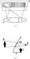
Fig. 2 shows a flowchart of virtual data display, which includes proposeddevice 1, set on thevehicle torpedo 7, projectingvirtual image 9 through the film (holographic) 10 on thevehicle windscreen 4 towards theeyes 8 of the driver. -
Fig. 3 shows a flowchart of the real data display, which includes proposeddevice 1, set on thevehicle torpedo 7, projecting virtual image onto the film (holographic) 11 on thevehicle windscreen 4. -
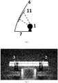
Fig. 4 shows a prototype of the device, which includes virtual image display system 2 (without a windscreen film), real image display system 3 (without a windscreen film). - The holographic image in this work means a film, which has a certain phase structure recorded so that in the first case, the film in the narrow spectral range based on the recorded structure replaces work of such optical elements as a flat mirror, a mirror with a certain curvature or lens, and in the second case it works as a diffuser box of the part of incident light in a wide spectral range.
- The data display device includes the following elements: controller, speed sensor, virtual
image display system image display system 3 and 5, compact body. At the same time, the virtualimage display system virtual image 9, including a set of optical elements 1 (lenses, and/or mirrors, and/or holographic elements) and thefilm 10 on thevehicle windscreen 4, functioning as a optical element, such as spherical mirror at the designed wavelength, which is either a holographic image or light-induced grating recorded to work at a certain wavelength and is transparent to the rest of the visible spectrum, or a color filter that reflects light at a certain wavelength and is transparent to the rest of the visible spectrum. The realimage display system 3 and 5 includes sources of visible light (laser and/or laser diodes, and/or LEDs, and/or phosphors for conversion of light), illumination optical components, matrix and optical components generating real image, comprising in turn a set ofoptical elements 1 and partially transparent film (with the transmission factor for visible spectrum over 70%) 11 on thevehicle windscreen 4, which diffusely reflects only a preselected portion of the spectrum of visible light;Compact body 1 contains controller, part of the elements of the virtual and real image display system, except of thefilms 5 and 6 on thevehicle windscreen 4. The device can be designed so that the film of the virtualimage display system 6 is sticked on the film of the real image display system 5. - The device works as follows. Information (image) to be displayed for the driver is generated on the matrix illuminated by the coherent source in case of the virtual image display system or illuminated by the visible light sources in case of real image display system. At the same time, matrices for two systems can be different. Then, the optical components of the virtual image display system generate a
virtual image 9. Either the optical components of the real image display system generate an image on thefilm 11 of thewindscreen 4. Dupont diffuse film, which is transparent in the entire visible range and only part of the light (in the range of 15 to 30%) diffusely back-reflects, can be used as a film of the optical components of real image display system. - The following example shows the work of the device more clearly. The controller receives the speed value of the vehicle from the speed sensor and compares it with the threshold value (may range from 0 to 40 km/h), which switches the virtual
image display system image display system 3, 5. At the same time, depending on the vehicle speed, the controller chooses the data to be displayed and to be blocked. For example, at the speed over 120 km/h, only virtual image display system is switched and only the data on the current vehicle speed and the speed limit for the present area of the road, as well as possible obstacles ahead are transmitted. At the speed from 20 km/h to 120 km/h, the controller can also allow to display data on the upcoming maneuvers through the virtual image display system. At the speed below 20 km/h, the real image display system is on, and the data on the cultural, leisure, entertainment, sport, art facilities located in the immediate vicinity of the vehicle, as well as advertising are displayed. - The device can include a position detector (e.g., GPS and/ or GLONASS receiver) and location databases.
- In this case, the device works as follows. The controller receives the data (e.g., position coordinates) from the vehicle position detector and then it finds the appropriate data in the database (e.g., data on on the cultural, leisure, entertainment, sport, art facilities located in the immediate vicinity), and displays them through one of the image display systems. The described method allows to get the access to the interactive information via a wireless connection safely for driver while driving the vehicle. The control can be carried out either by voice, or by the buttons on the steering wheel or via the onboard computer. At the same time, the databases can be located on the remote server and accessed on-line or be uploaded into the device, which can be periodically updated.
- Technical result of the claimed invention is to ensure safe driving and high-quality image displayed with the help of combined use of 2 display systems depending on the speed of the vehicle, as well as to provide to the driver maximum possible data with the minimal risk of the accident.
Claims (17)
- Method of transmitting of the visual data to the driver via at least two optical systems, controller, speed sensor, comprises the following stagesa. obtain speed value from the speed sensor of the vehicle and transmit the speed data to the controller;b. use the controller to compare obtained speed value to the threshold value;c. switch at least one of the optical systems and turn off all other, if the measured speed is above the threshold.
- Method of claim 1 characterized by the fact that the threshold speed is in the range of 0-40 km/h.
- Method of claim 2 characterized by the fact that one optical system forms a real image on the windscreen, and the second generates a virtual (ahead of the car) image beyond the windscreen.
- Method of claim 3 characterized by the fact that the controller is used to switch the optical system of displaying real image onto the windscreen of the vehicle and to turn off the optical system of displaying virtual (ahead of the car) image behind the windscreen of the vehicle, if the vehicle speed is below a threshold value; and the controller is used to switch the optical system of displaying of virtual image behind the windscreen of the vehicle, and turn off optical system of displaying of real image onto the windscreen of the vehicle, if the vehicle speed is higher than and/or equal to the threshold.
- Method of claim 4 characterized by the fact that the position detector and the database is used to take the following steps:a. take readings of the vehicle position detector using controller;b. obtain reference data, corresponding to the position detector data, from the database;c. transmit reference data from the database to the driver, using at least one of the optical systems.
- Method of claim 5 characterized by the fact that the GPS receiver and/or GLONASS is used as a position detector.
- Method of claim 6 characterized by the fact that the information on cultural, leisure, entertainment, sport, art facilities located in the immediate vicinity can be used as reference information.
- Method of claim 7 characterized by the fact that the databases can be located on the remote server and accessed on-line or be uploaded into the device, which can be periodically updated.
- Method of any of the claims. 1-8 characterized by the fact that based on the speed of the vehicle, the controller chooses the data to be showed via the appropriate image display system, and the data to be blocked.
- The data display device includes the following elements:a. controller;b. speed sensor;c. virtual image display system which includes a coherent light source, illumination optical components, matrix and optical components generating virtual image, including in turn a set of optical elements and the film on the vehicle windscreen, which is either a holographic image or light-induced grating recorded to work at a certain wavelength and is transparent to the rest of the visible spectrum, or a color filter that reflects light at a certain wavelength and is transparent to the rest of the visible spectrum;d. real image display system which includes sources of visible light, illumination optical components, matrix and optical components generating real image, comprising in turn a set of optical elements and partially a transparent film on the vehicle windscreen, which diffusely reflects only a preselected portion of the spectrum of visible light;e. compact body, containing controller, part of the elements of the virtual and real image display system, except of the film on the vehicle windscreen.
- The device of claim 10 characterized by the fact that it switches also a position detector, which is GPS and/or GLONASS receiver.
- The device of claim 11 characterized by the fact that it uses laser or laser diode as a coherent light source for the virtual image display system.
- The device of claim 12 characterized by the fact that it uses DLP matrix, or LCD matrix, or LCoS matrix as a matrix for the virtual and/or real image display system.
- The device of claim 13 characterized by the fact that it uses lenses and/or mirrors and/or holographic images as optical elements for the virtual or real image display system.
- The device of claim 14 characterized by the fact that it uses laser and/or laser diodes, and/or LEDs, and/or phosphors for conversion of light to visible light sources for the real image display system.
- The device of claim 15 characterized by the fact that the transmission factor of the partially transparent film of the real image display system for visible spectrum is over 70%.
- The device of claim 16 characterized by the fact that the film of the virtual image display system is laminated on top of the film of the real image display system.
Applications Claiming Priority (1)
| Application Number | Priority Date | Filing Date | Title |
|---|---|---|---|
| PCT/RU2014/000231 WO2015152753A1 (en) | 2014-03-31 | 2014-03-31 | Method of displaying information through automobile windshield, and device for implementing same |
Publications (3)
| Publication Number | Publication Date |
|---|---|
| EP3128356A1 true EP3128356A1 (en) | 2017-02-08 |
| EP3128356A4 EP3128356A4 (en) | 2018-05-02 |
| EP3128356B1 EP3128356B1 (en) | 2020-05-06 |
Family
ID=54240924
Family Applications (1)
| Application Number | Title | Priority Date | Filing Date |
|---|---|---|---|
| EP14888287.1A Active EP3128356B1 (en) | 2014-03-31 | 2014-03-31 | Method of displaying information through automobile windshield, and device for implementing same |
Country Status (4)
| Country | Link |
|---|---|
| US (1) | US10444518B2 (en) |
| EP (1) | EP3128356B1 (en) |
| CN (1) | CN106233184B (en) |
| WO (1) | WO2015152753A1 (en) |
Cited By (2)
| Publication number | Priority date | Publication date | Assignee | Title |
|---|---|---|---|---|
| EP3246745A1 (en) * | 2016-05-13 | 2017-11-22 | Visteon Global Technologies, Inc. | Display unit and method for representing information |
| US20230316914A1 (en) * | 2022-04-01 | 2023-10-05 | GM Global Technology Operations LLC | System and method for providing platooning information using an augmented reality display |
Families Citing this family (10)
| Publication number | Priority date | Publication date | Assignee | Title |
|---|---|---|---|---|
| JP6201064B2 (en) * | 2014-12-24 | 2017-09-27 | 富士フイルム株式会社 | Projection display device, safe driving support method, and safe driving support program |
| US11305766B2 (en) * | 2016-09-26 | 2022-04-19 | Iprd Group, Llc | Combining driver alertness with advanced driver assistance systems (ADAS) |
| CA3062501A1 (en) * | 2017-05-11 | 2018-11-15 | Saint-Gobain Glass France | Hud system and method for hud image generation |
| JP6877842B2 (en) * | 2017-07-20 | 2021-05-26 | アルパイン株式会社 | In-vehicle display system |
| KR102441571B1 (en) * | 2017-10-12 | 2022-09-08 | 현대자동차주식회사 | Rear lamp apparatus of vehicle |
| KR102446387B1 (en) * | 2017-11-29 | 2022-09-22 | 삼성전자주식회사 | Electronic apparatus and method for providing a text thereof |
| US11686938B2 (en) | 2020-12-16 | 2023-06-27 | Samsung Electronics Co., Ltd. | Augmented reality device for providing 3D augmented reality and operating method of the same |
| WO2023022023A1 (en) * | 2021-08-20 | 2023-02-23 | 京セラ株式会社 | Aerial image display apparatus |
| WO2024025016A1 (en) * | 2022-07-29 | 2024-02-01 | 엘지전자 주식회사 | Ar signage display device of vehicle and operation method thereof |
| WO2024025018A1 (en) * | 2022-07-29 | 2024-02-01 | 엘지전자 주식회사 | Ar signage display device of vehicle and operating method thereof |
Citations (3)
| Publication number | Priority date | Publication date | Assignee | Title |
|---|---|---|---|---|
| US5510983A (en) | 1992-11-13 | 1996-04-23 | Yazaki Corporation | On-vehicle display |
| US20090231698A1 (en) | 2005-10-26 | 2009-09-17 | Nippon Sheet Glass Company, Limited | In-vehicle stereoimage display apparatus |
| US20140036374A1 (en) | 2012-08-01 | 2014-02-06 | Microvision Inc. | Bifocal Head-up Display System |
Family Cites Families (45)
| Publication number | Priority date | Publication date | Assignee | Title |
|---|---|---|---|---|
| US3560921A (en) | 1968-12-19 | 1971-02-02 | Ford Motor Co | Automotive vehicle condition indicator utilizing holograms |
| GB1418891A (en) | 1972-01-28 | 1975-12-24 | Nat Res Dev | Headup display aparatus |
| DE3532120A1 (en) | 1985-09-10 | 1987-03-19 | Ver Glaswerke Gmbh | WINDSHIELD WITH A REFLECTIVE DEVICE FOR MIRRORING OPTICAL SIGNALS INTO THE FIELD OF THE DRIVER |
| US4790613A (en) | 1987-01-06 | 1988-12-13 | Hughes Aircraft Company | Holographic display panel for a vehicle windshield |
| DE4445555C2 (en) | 1993-12-24 | 2002-07-18 | Hyundai Autonet Co | Field of view display device for vehicles |
| US5677701A (en) | 1994-04-27 | 1997-10-14 | Nippondenso Co., Ltd. | Head-up displaying device for a vehicle |
| US20040204848A1 (en) * | 2002-06-20 | 2004-10-14 | Shigeru Matsuo | Navigation apparatus for receiving delivered information |
| JP2004168230A (en) * | 2002-11-21 | 2004-06-17 | Nissan Motor Co Ltd | Display device for vehicle |
| JP2007308084A (en) * | 2006-05-22 | 2007-11-29 | Fujitsu Ten Ltd | On-vehicle display device and acoustic control method |
| US20090128630A1 (en) * | 2006-07-06 | 2009-05-21 | Nissan Motor Co., Ltd. | Vehicle image display system and image display method |
| US20080133133A1 (en) * | 2006-12-04 | 2008-06-05 | Abels Steven M | System and method of enabling features based on geographic imposed rules |
| US7688516B2 (en) * | 2007-05-11 | 2010-03-30 | Lg Electronics Inc. | Head-up display device for vehicles |
| TWI425524B (en) * | 2007-05-30 | 2014-02-01 | Opus Microsystems Corp | Head-up display system |
| JP4475308B2 (en) * | 2007-09-18 | 2010-06-09 | 株式会社デンソー | Display device |
| US8786467B2 (en) * | 2007-11-14 | 2014-07-22 | The Boeing Company | Methods and systems for filtering traffic information for display |
| JP4480755B2 (en) * | 2007-12-04 | 2010-06-16 | カルソニックカンセイ株式会社 | Head-up display device for vehicle |
| US20090177393A1 (en) * | 2008-01-07 | 2009-07-09 | Simone Francine Tertoolen | Navigation device and method |
| FR2929016B1 (en) * | 2008-03-19 | 2010-06-04 | Saint Gobain | HEAD VISUALIZATION DEVICE. |
| TW201008812A (en) * | 2008-08-22 | 2010-03-01 | shi-xiong Li | Auxiliary video warning device for vehicle |
| JP5087051B2 (en) * | 2009-07-02 | 2012-11-28 | 富士通テン株式会社 | Image generating apparatus and image display system |
| US8547435B2 (en) * | 2009-09-20 | 2013-10-01 | Selka Elektronik ve Internet Urunleri San.ve Tic.A.S | Mobile security audio-video recorder with local storage and continuous recording loop |
| JP5392612B2 (en) * | 2009-09-28 | 2014-01-22 | スタンレー電気株式会社 | Display device |
| US20110115913A1 (en) * | 2009-11-17 | 2011-05-19 | Werner Lang | Automated vehicle surrounding area monitor and display system |
| US8386173B2 (en) * | 2010-01-11 | 2013-02-26 | Mitac International Corp. | Adjusting a level of map detail displayed on a personal navigation device according to detected speed |
| JP2011253097A (en) * | 2010-06-03 | 2011-12-15 | Toshiba Corp | Display device and display method |
| WO2012003213A1 (en) * | 2010-06-30 | 2012-01-05 | 3M Innovative Properties Company | Diffuse reflective optical films with spatially selective birefringence reduction |
| US9268134B2 (en) | 2010-08-27 | 2016-02-23 | Empire Technology Development Llc | Head up display |
| JP5569365B2 (en) * | 2010-11-30 | 2014-08-13 | アイシン・エィ・ダブリュ株式会社 | Guide device, guide method, and guide program |
| DE102011006347B4 (en) * | 2011-03-29 | 2023-02-09 | Bayerische Motoren Werke Aktiengesellschaft | Process for outputting graphical driving instructions |
| US20120287277A1 (en) * | 2011-05-13 | 2012-11-15 | Koehrsen Craig L | Machine display system |
| GB2495694B (en) * | 2011-09-02 | 2017-11-08 | Skype | Mobile video calls |
| US20130120850A1 (en) * | 2011-11-16 | 2013-05-16 | Delphi Technologies, Inc. | Heads-up display system |
| US8854281B2 (en) * | 2011-12-02 | 2014-10-07 | Automotive Research & Test Center | Head up display (HUD) |
| FR2985042B1 (en) * | 2011-12-22 | 2014-01-17 | Saint Gobain | DEVICE FOR VISUALIZING AN IMAGE ON A SHEET SUPPORT |
| JP6004706B2 (en) * | 2012-04-04 | 2016-10-12 | 三菱電機株式会社 | Display device and head-up display system provided with the same |
| KR102028720B1 (en) * | 2012-07-10 | 2019-11-08 | 삼성전자주식회사 | Transparent display apparatus for displaying an information of danger element and method thereof |
| US9453740B2 (en) * | 2012-10-30 | 2016-09-27 | Alpine Electronics, Inc. | Method of displaying objects on navigation map |
| CA2901599C (en) * | 2012-12-04 | 2022-09-06 | L-3 Communications Corporation | Combined hud/hdd display |
| EP2936235B1 (en) * | 2012-12-21 | 2021-10-13 | Harman Becker Automotive Systems GmbH | System for a vehicle |
| JP6015459B2 (en) * | 2013-01-18 | 2016-10-26 | 株式会社デンソー | Vehicle navigation device |
| JP5772841B2 (en) * | 2013-01-23 | 2015-09-02 | 株式会社デンソー | Vehicle display device |
| US9047703B2 (en) * | 2013-03-13 | 2015-06-02 | Honda Motor Co., Ltd. | Augmented reality heads up display (HUD) for left turn safety cues |
| US20140281971A1 (en) * | 2013-03-13 | 2014-09-18 | United Video Properties, Inc. | Methods and systems for generating objective specific playlists |
| US9758099B2 (en) * | 2013-03-15 | 2017-09-12 | Gentex Corporation | Display system and method thereof |
| FR3013462B1 (en) * | 2013-11-18 | 2017-06-09 | Commissariat Energie Atomique | SYSTEM FOR DISPLAYING AN IMAGE ON A WINDSHIELD |
-
2014
- 2014-03-31 US US15/128,928 patent/US10444518B2/en active Active
- 2014-03-31 EP EP14888287.1A patent/EP3128356B1/en active Active
- 2014-03-31 WO PCT/RU2014/000231 patent/WO2015152753A1/en active Application Filing
- 2014-03-31 CN CN201480077680.5A patent/CN106233184B/en active Active
Patent Citations (3)
| Publication number | Priority date | Publication date | Assignee | Title |
|---|---|---|---|---|
| US5510983A (en) | 1992-11-13 | 1996-04-23 | Yazaki Corporation | On-vehicle display |
| US20090231698A1 (en) | 2005-10-26 | 2009-09-17 | Nippon Sheet Glass Company, Limited | In-vehicle stereoimage display apparatus |
| US20140036374A1 (en) | 2012-08-01 | 2014-02-06 | Microvision Inc. | Bifocal Head-up Display System |
Non-Patent Citations (1)
| Title |
|---|
| See also references of WO2015152753A1 |
Cited By (2)
| Publication number | Priority date | Publication date | Assignee | Title |
|---|---|---|---|---|
| EP3246745A1 (en) * | 2016-05-13 | 2017-11-22 | Visteon Global Technologies, Inc. | Display unit and method for representing information |
| US20230316914A1 (en) * | 2022-04-01 | 2023-10-05 | GM Global Technology Operations LLC | System and method for providing platooning information using an augmented reality display |
Also Published As
| Publication number | Publication date |
|---|---|
| CN106233184B (en) | 2019-12-20 |
| US10444518B2 (en) | 2019-10-15 |
| WO2015152753A1 (en) | 2015-10-08 |
| EP3128356A4 (en) | 2018-05-02 |
| US20170102550A1 (en) | 2017-04-13 |
| EP3128356B1 (en) | 2020-05-06 |
| CN106233184A (en) | 2016-12-14 |
Similar Documents
| Publication | Publication Date | Title |
|---|---|---|
| EP3128356B1 (en) | Method of displaying information through automobile windshield, and device for implementing same | |
| WO2017134866A1 (en) | Head-up display device | |
| US6359737B1 (en) | Combined head-up display | |
| WO2017134865A1 (en) | Head-up display device | |
| US10895741B2 (en) | Ultra-wide head-up display system and display method thereof | |
| US9131153B2 (en) | Rearview panoramic head-up display device for vehicles | |
| US10302953B2 (en) | Adjustable head-up display arrangement for a vehicle | |
| CN104730712A (en) | Display apparatus and method for vehicle | |
| JP2019113809A (en) | Head-up display device | |
| CN205880369U (en) | Utilize car windscreen to realize equipment that comes back and show | |
| JP6081603B2 (en) | Prism correction lens | |
| Maroto et al. | Head-up Displays (HUD) in driving | |
| JP2019174693A (en) | Display system, control unit, control method, program, and movable body | |
| CN104015658A (en) | Automotive rearview panorama head-up display device | |
| CN106526858A (en) | DLP-based vehicle-mounted head-up display optical system | |
| WO2017028411A1 (en) | Head-up display, head-up display method and vehicle-mounted display device | |
| JP2019119248A (en) | Head-up display device | |
| WO2019208365A1 (en) | Information display device | |
| CN204821323U (en) | Vehicle -mounted electronic equipment | |
| RU2573167C2 (en) | Data display through vehicle windshield and device to this end | |
| KR20110016118A (en) | Head up display for navigation | |
| CN115685654A (en) | Projection device, vehicle and display apparatus | |
| CN213750498U (en) | Vehicle-mounted augmented reality head-up display device | |
| RU155549U1 (en) | DEVICE FOR DISPLAYING INFORMATION | |
| JP2019061088A (en) | Virtual image display unit, virtual image display method, and virtual image display program |
Legal Events
| Date | Code | Title | Description |
|---|---|---|---|
| STAA | Information on the status of an ep patent application or granted ep patent |
Free format text: STATUS: THE INTERNATIONAL PUBLICATION HAS BEEN MADE |
|
| PUAI | Public reference made under article 153(3) epc to a published international application that has entered the european phase |
Free format text: ORIGINAL CODE: 0009012 |
|
| STAA | Information on the status of an ep patent application or granted ep patent |
Free format text: STATUS: REQUEST FOR EXAMINATION WAS MADE |
|
| 17P | Request for examination filed |
Effective date: 20161028 |
|
| AK | Designated contracting states |
Kind code of ref document: A1 Designated state(s): AL AT BE BG CH CY CZ DE DK EE ES FI FR GB GR HR HU IE IS IT LI LT LU LV MC MK MT NL NO PL PT RO RS SE SI SK SM TR |
|
| AX | Request for extension of the european patent |
Extension state: BA ME |
|
| DAX | Request for extension of the european patent (deleted) | ||
| TPAC | Observations filed by third parties |
Free format text: ORIGINAL CODE: EPIDOSNTIPA |
|
| A4 | Supplementary search report drawn up and despatched |
Effective date: 20180405 |
|
| RIC1 | Information provided on ipc code assigned before grant |
Ipc: G02B 27/01 20060101AFI20180323BHEP Ipc: B60K 35/00 20060101ALI20180323BHEP |
|
| RAP1 | Party data changed (applicant data changed or rights of an application transferred) |
Owner name: WAYRAY SA |
|
| RAP1 | Party data changed (applicant data changed or rights of an application transferred) |
Owner name: WAYRAY SA |
|
| GRAP | Despatch of communication of intention to grant a patent |
Free format text: ORIGINAL CODE: EPIDOSNIGR1 |
|
| STAA | Information on the status of an ep patent application or granted ep patent |
Free format text: STATUS: GRANT OF PATENT IS INTENDED |
|
| INTG | Intention to grant announced |
Effective date: 20190411 |
|
| GRAJ | Information related to disapproval of communication of intention to grant by the applicant or resumption of examination proceedings by the epo deleted |
Free format text: ORIGINAL CODE: EPIDOSDIGR1 |
|
| STAA | Information on the status of an ep patent application or granted ep patent |
Free format text: STATUS: REQUEST FOR EXAMINATION WAS MADE |
|
| INTC | Intention to grant announced (deleted) | ||
| GRAS | Grant fee paid |
Free format text: ORIGINAL CODE: EPIDOSNIGR3 |
|
| STAA | Information on the status of an ep patent application or granted ep patent |
Free format text: STATUS: GRANT OF PATENT IS INTENDED |
|
| GRAP | Despatch of communication of intention to grant a patent |
Free format text: ORIGINAL CODE: EPIDOSNIGR1 |
|
| RAP1 | Party data changed (applicant data changed or rights of an application transferred) |
Owner name: WAYRAY AG |
|
| INTG | Intention to grant announced |
Effective date: 20191030 |
|
| GRAA | (expected) grant |
Free format text: ORIGINAL CODE: 0009210 |
|
| STAA | Information on the status of an ep patent application or granted ep patent |
Free format text: STATUS: THE PATENT HAS BEEN GRANTED |
|
| AK | Designated contracting states |
Kind code of ref document: B1 Designated state(s): AL AT BE BG CH CY CZ DE DK EE ES FI FR GB GR HR HU IE IS IT LI LT LU LV MC MK MT NL NO PL PT RO RS SE SI SK SM TR |
|
| REG | Reference to a national code |
Ref country code: GB Ref legal event code: FG4D |
|
| REG | Reference to a national code |
Ref country code: CH Ref legal event code: EP Ref country code: AT Ref legal event code: REF Ref document number: 1267700 Country of ref document: AT Kind code of ref document: T Effective date: 20200515 |
|
| REG | Reference to a national code |
Ref country code: IE Ref legal event code: FG4D |
|
| REG | Reference to a national code |
Ref country code: DE Ref legal event code: R096 Ref document number: 602014065292 Country of ref document: DE |
|
| REG | Reference to a national code |
Ref country code: CH Ref legal event code: NV Representative=s name: IPRIME RENTSCH KAELIN AG, CH |
|
| REG | Reference to a national code |
Ref country code: LT Ref legal event code: MG4D |
|
| REG | Reference to a national code |
Ref country code: NL Ref legal event code: MP Effective date: 20200506 |
|
| PG25 | Lapsed in a contracting state [announced via postgrant information from national office to epo] |
Ref country code: GR Free format text: LAPSE BECAUSE OF FAILURE TO SUBMIT A TRANSLATION OF THE DESCRIPTION OR TO PAY THE FEE WITHIN THE PRESCRIBED TIME-LIMIT Effective date: 20200807 Ref country code: FI Free format text: LAPSE BECAUSE OF FAILURE TO SUBMIT A TRANSLATION OF THE DESCRIPTION OR TO PAY THE FEE WITHIN THE PRESCRIBED TIME-LIMIT Effective date: 20200506 Ref country code: NO Free format text: LAPSE BECAUSE OF FAILURE TO SUBMIT A TRANSLATION OF THE DESCRIPTION OR TO PAY THE FEE WITHIN THE PRESCRIBED TIME-LIMIT Effective date: 20200806 Ref country code: IS Free format text: LAPSE BECAUSE OF FAILURE TO SUBMIT A TRANSLATION OF THE DESCRIPTION OR TO PAY THE FEE WITHIN THE PRESCRIBED TIME-LIMIT Effective date: 20200906 Ref country code: LT Free format text: LAPSE BECAUSE OF FAILURE TO SUBMIT A TRANSLATION OF THE DESCRIPTION OR TO PAY THE FEE WITHIN THE PRESCRIBED TIME-LIMIT Effective date: 20200506 Ref country code: SE Free format text: LAPSE BECAUSE OF FAILURE TO SUBMIT A TRANSLATION OF THE DESCRIPTION OR TO PAY THE FEE WITHIN THE PRESCRIBED TIME-LIMIT Effective date: 20200506 Ref country code: PT Free format text: LAPSE BECAUSE OF FAILURE TO SUBMIT A TRANSLATION OF THE DESCRIPTION OR TO PAY THE FEE WITHIN THE PRESCRIBED TIME-LIMIT Effective date: 20200907 |
|
| PG25 | Lapsed in a contracting state [announced via postgrant information from national office to epo] |
Ref country code: HR Free format text: LAPSE BECAUSE OF FAILURE TO SUBMIT A TRANSLATION OF THE DESCRIPTION OR TO PAY THE FEE WITHIN THE PRESCRIBED TIME-LIMIT Effective date: 20200506 Ref country code: LV Free format text: LAPSE BECAUSE OF FAILURE TO SUBMIT A TRANSLATION OF THE DESCRIPTION OR TO PAY THE FEE WITHIN THE PRESCRIBED TIME-LIMIT Effective date: 20200506 Ref country code: RS Free format text: LAPSE BECAUSE OF FAILURE TO SUBMIT A TRANSLATION OF THE DESCRIPTION OR TO PAY THE FEE WITHIN THE PRESCRIBED TIME-LIMIT Effective date: 20200506 Ref country code: BG Free format text: LAPSE BECAUSE OF FAILURE TO SUBMIT A TRANSLATION OF THE DESCRIPTION OR TO PAY THE FEE WITHIN THE PRESCRIBED TIME-LIMIT Effective date: 20200806 |
|
| REG | Reference to a national code |
Ref country code: AT Ref legal event code: MK05 Ref document number: 1267700 Country of ref document: AT Kind code of ref document: T Effective date: 20200506 |
|
| PG25 | Lapsed in a contracting state [announced via postgrant information from national office to epo] |
Ref country code: AL Free format text: LAPSE BECAUSE OF FAILURE TO SUBMIT A TRANSLATION OF THE DESCRIPTION OR TO PAY THE FEE WITHIN THE PRESCRIBED TIME-LIMIT Effective date: 20200506 Ref country code: NL Free format text: LAPSE BECAUSE OF FAILURE TO SUBMIT A TRANSLATION OF THE DESCRIPTION OR TO PAY THE FEE WITHIN THE PRESCRIBED TIME-LIMIT Effective date: 20200506 |
|
| PG25 | Lapsed in a contracting state [announced via postgrant information from national office to epo] |
Ref country code: ES Free format text: LAPSE BECAUSE OF FAILURE TO SUBMIT A TRANSLATION OF THE DESCRIPTION OR TO PAY THE FEE WITHIN THE PRESCRIBED TIME-LIMIT Effective date: 20200506 Ref country code: RO Free format text: LAPSE BECAUSE OF FAILURE TO SUBMIT A TRANSLATION OF THE DESCRIPTION OR TO PAY THE FEE WITHIN THE PRESCRIBED TIME-LIMIT Effective date: 20200506 Ref country code: CZ Free format text: LAPSE BECAUSE OF FAILURE TO SUBMIT A TRANSLATION OF THE DESCRIPTION OR TO PAY THE FEE WITHIN THE PRESCRIBED TIME-LIMIT Effective date: 20200506 Ref country code: EE Free format text: LAPSE BECAUSE OF FAILURE TO SUBMIT A TRANSLATION OF THE DESCRIPTION OR TO PAY THE FEE WITHIN THE PRESCRIBED TIME-LIMIT Effective date: 20200506 Ref country code: DK Free format text: LAPSE BECAUSE OF FAILURE TO SUBMIT A TRANSLATION OF THE DESCRIPTION OR TO PAY THE FEE WITHIN THE PRESCRIBED TIME-LIMIT Effective date: 20200506 Ref country code: IT Free format text: LAPSE BECAUSE OF FAILURE TO SUBMIT A TRANSLATION OF THE DESCRIPTION OR TO PAY THE FEE WITHIN THE PRESCRIBED TIME-LIMIT Effective date: 20200506 Ref country code: AT Free format text: LAPSE BECAUSE OF FAILURE TO SUBMIT A TRANSLATION OF THE DESCRIPTION OR TO PAY THE FEE WITHIN THE PRESCRIBED TIME-LIMIT Effective date: 20200506 Ref country code: SM Free format text: LAPSE BECAUSE OF FAILURE TO SUBMIT A TRANSLATION OF THE DESCRIPTION OR TO PAY THE FEE WITHIN THE PRESCRIBED TIME-LIMIT Effective date: 20200506 |
|
| REG | Reference to a national code |
Ref country code: DE Ref legal event code: R097 Ref document number: 602014065292 Country of ref document: DE |
|
| PG25 | Lapsed in a contracting state [announced via postgrant information from national office to epo] |
Ref country code: PL Free format text: LAPSE BECAUSE OF FAILURE TO SUBMIT A TRANSLATION OF THE DESCRIPTION OR TO PAY THE FEE WITHIN THE PRESCRIBED TIME-LIMIT Effective date: 20200506 Ref country code: SK Free format text: LAPSE BECAUSE OF FAILURE TO SUBMIT A TRANSLATION OF THE DESCRIPTION OR TO PAY THE FEE WITHIN THE PRESCRIBED TIME-LIMIT Effective date: 20200506 |
|
| PLBE | No opposition filed within time limit |
Free format text: ORIGINAL CODE: 0009261 |
|
| STAA | Information on the status of an ep patent application or granted ep patent |
Free format text: STATUS: NO OPPOSITION FILED WITHIN TIME LIMIT |
|
| 26N | No opposition filed |
Effective date: 20210209 |
|
| PG25 | Lapsed in a contracting state [announced via postgrant information from national office to epo] |
Ref country code: SI Free format text: LAPSE BECAUSE OF FAILURE TO SUBMIT A TRANSLATION OF THE DESCRIPTION OR TO PAY THE FEE WITHIN THE PRESCRIBED TIME-LIMIT Effective date: 20200506 |
|
| PG25 | Lapsed in a contracting state [announced via postgrant information from national office to epo] |
Ref country code: MC Free format text: LAPSE BECAUSE OF FAILURE TO SUBMIT A TRANSLATION OF THE DESCRIPTION OR TO PAY THE FEE WITHIN THE PRESCRIBED TIME-LIMIT Effective date: 20200506 |
|
| REG | Reference to a national code |
Ref country code: BE Ref legal event code: MM Effective date: 20210331 |
|
| PG25 | Lapsed in a contracting state [announced via postgrant information from national office to epo] |
Ref country code: IE Free format text: LAPSE BECAUSE OF NON-PAYMENT OF DUE FEES Effective date: 20210331 Ref country code: LU Free format text: LAPSE BECAUSE OF NON-PAYMENT OF DUE FEES Effective date: 20210331 |
|
| PG25 | Lapsed in a contracting state [announced via postgrant information from national office to epo] |
Ref country code: BE Free format text: LAPSE BECAUSE OF NON-PAYMENT OF DUE FEES Effective date: 20210331 |
|
| PGFP | Annual fee paid to national office [announced via postgrant information from national office to epo] |
Ref country code: FR Payment date: 20230324 Year of fee payment: 10 |
|
| PG25 | Lapsed in a contracting state [announced via postgrant information from national office to epo] |
Ref country code: HU Free format text: LAPSE BECAUSE OF FAILURE TO SUBMIT A TRANSLATION OF THE DESCRIPTION OR TO PAY THE FEE WITHIN THE PRESCRIBED TIME-LIMIT; INVALID AB INITIO Effective date: 20140331 |
|
| PGFP | Annual fee paid to national office [announced via postgrant information from national office to epo] |
Ref country code: GB Payment date: 20230322 Year of fee payment: 10 Ref country code: DE Payment date: 20230321 Year of fee payment: 10 |
|
| PG25 | Lapsed in a contracting state [announced via postgrant information from national office to epo] |
Ref country code: CY Free format text: LAPSE BECAUSE OF FAILURE TO SUBMIT A TRANSLATION OF THE DESCRIPTION OR TO PAY THE FEE WITHIN THE PRESCRIBED TIME-LIMIT Effective date: 20200506 |
|
| PGFP | Annual fee paid to national office [announced via postgrant information from national office to epo] |
Ref country code: CH Payment date: 20230401 Year of fee payment: 10 |