EP3106193A1 - Safety device for syringes designed to be pre-filled - Google Patents
Safety device for syringes designed to be pre-filled Download PDFInfo
- Publication number
- EP3106193A1 EP3106193A1 EP15172153.7A EP15172153A EP3106193A1 EP 3106193 A1 EP3106193 A1 EP 3106193A1 EP 15172153 A EP15172153 A EP 15172153A EP 3106193 A1 EP3106193 A1 EP 3106193A1
- Authority
- EP
- European Patent Office
- Prior art keywords
- syringe body
- safety device
- guide pin
- gate area
- syringe
- Prior art date
- Legal status (The legal status is an assumption and is not a legal conclusion. Google has not performed a legal analysis and makes no representation as to the accuracy of the status listed.)
- Granted
Links
Images


Classifications
-
- A—HUMAN NECESSITIES
- A61—MEDICAL OR VETERINARY SCIENCE; HYGIENE
- A61M—DEVICES FOR INTRODUCING MEDIA INTO, OR ONTO, THE BODY; DEVICES FOR TRANSDUCING BODY MEDIA OR FOR TAKING MEDIA FROM THE BODY; DEVICES FOR PRODUCING OR ENDING SLEEP OR STUPOR
- A61M5/00—Devices for bringing media into the body in a subcutaneous, intra-vascular or intramuscular way; Accessories therefor, e.g. filling or cleaning devices, arm-rests
- A61M5/178—Syringes
- A61M5/31—Details
- A61M5/32—Needles; Details of needles pertaining to their connection with syringe or hub; Accessories for bringing the needle into, or holding the needle on, the body; Devices for protection of needles
- A61M5/3202—Devices for protection of the needle before use, e.g. caps
-
- A—HUMAN NECESSITIES
- A61—MEDICAL OR VETERINARY SCIENCE; HYGIENE
- A61M—DEVICES FOR INTRODUCING MEDIA INTO, OR ONTO, THE BODY; DEVICES FOR TRANSDUCING BODY MEDIA OR FOR TAKING MEDIA FROM THE BODY; DEVICES FOR PRODUCING OR ENDING SLEEP OR STUPOR
- A61M5/00—Devices for bringing media into the body in a subcutaneous, intra-vascular or intramuscular way; Accessories therefor, e.g. filling or cleaning devices, arm-rests
- A61M5/178—Syringes
- A61M5/31—Details
- A61M5/32—Needles; Details of needles pertaining to their connection with syringe or hub; Accessories for bringing the needle into, or holding the needle on, the body; Devices for protection of needles
- A61M5/3205—Apparatus for removing or disposing of used needles or syringes, e.g. containers; Means for protection against accidental injuries from used needles
- A61M5/321—Means for protection against accidental injuries by used needles
- A61M5/3243—Means for protection against accidental injuries by used needles being axially-extensible, e.g. protective sleeves coaxially slidable on the syringe barrel
- A61M5/326—Fully automatic sleeve extension, i.e. in which triggering of the sleeve does not require a deliberate action by the user
-
- A—HUMAN NECESSITIES
- A61—MEDICAL OR VETERINARY SCIENCE; HYGIENE
- A61M—DEVICES FOR INTRODUCING MEDIA INTO, OR ONTO, THE BODY; DEVICES FOR TRANSDUCING BODY MEDIA OR FOR TAKING MEDIA FROM THE BODY; DEVICES FOR PRODUCING OR ENDING SLEEP OR STUPOR
- A61M5/00—Devices for bringing media into the body in a subcutaneous, intra-vascular or intramuscular way; Accessories therefor, e.g. filling or cleaning devices, arm-rests
- A61M5/178—Syringes
- A61M5/31—Details
- A61M5/32—Needles; Details of needles pertaining to their connection with syringe or hub; Accessories for bringing the needle into, or holding the needle on, the body; Devices for protection of needles
- A61M5/3205—Apparatus for removing or disposing of used needles or syringes, e.g. containers; Means for protection against accidental injuries from used needles
- A61M5/321—Means for protection against accidental injuries by used needles
- A61M5/3243—Means for protection against accidental injuries by used needles being axially-extensible, e.g. protective sleeves coaxially slidable on the syringe barrel
- A61M5/3271—Means for protection against accidental injuries by used needles being axially-extensible, e.g. protective sleeves coaxially slidable on the syringe barrel with guiding tracks for controlled sliding of needle protective sleeve from needle exposing to needle covering position
- A61M5/3272—Means for protection against accidental injuries by used needles being axially-extensible, e.g. protective sleeves coaxially slidable on the syringe barrel with guiding tracks for controlled sliding of needle protective sleeve from needle exposing to needle covering position having projections following labyrinth paths
-
- A—HUMAN NECESSITIES
- A61—MEDICAL OR VETERINARY SCIENCE; HYGIENE
- A61M—DEVICES FOR INTRODUCING MEDIA INTO, OR ONTO, THE BODY; DEVICES FOR TRANSDUCING BODY MEDIA OR FOR TAKING MEDIA FROM THE BODY; DEVICES FOR PRODUCING OR ENDING SLEEP OR STUPOR
- A61M5/00—Devices for bringing media into the body in a subcutaneous, intra-vascular or intramuscular way; Accessories therefor, e.g. filling or cleaning devices, arm-rests
- A61M5/178—Syringes
- A61M5/31—Details
- A61M2005/3103—Leak prevention means for distal end of syringes, i.e. syringe end for mounting a needle
- A61M2005/3107—Leak prevention means for distal end of syringes, i.e. syringe end for mounting a needle for needles
-
- A—HUMAN NECESSITIES
- A61—MEDICAL OR VETERINARY SCIENCE; HYGIENE
- A61M—DEVICES FOR INTRODUCING MEDIA INTO, OR ONTO, THE BODY; DEVICES FOR TRANSDUCING BODY MEDIA OR FOR TAKING MEDIA FROM THE BODY; DEVICES FOR PRODUCING OR ENDING SLEEP OR STUPOR
- A61M5/00—Devices for bringing media into the body in a subcutaneous, intra-vascular or intramuscular way; Accessories therefor, e.g. filling or cleaning devices, arm-rests
- A61M5/178—Syringes
- A61M5/31—Details
- A61M5/32—Needles; Details of needles pertaining to their connection with syringe or hub; Accessories for bringing the needle into, or holding the needle on, the body; Devices for protection of needles
- A61M5/3205—Apparatus for removing or disposing of used needles or syringes, e.g. containers; Means for protection against accidental injuries from used needles
- A61M5/321—Means for protection against accidental injuries by used needles
- A61M5/3243—Means for protection against accidental injuries by used needles being axially-extensible, e.g. protective sleeves coaxially slidable on the syringe barrel
- A61M5/326—Fully automatic sleeve extension, i.e. in which triggering of the sleeve does not require a deliberate action by the user
- A61M2005/3267—Biased sleeves where the needle is uncovered by insertion of the needle into a patient's body
Definitions
- the invention relates to a syringe body with an end arranged safety device to avoid puncture injuries, wherein the syringe body comprises an end arranged lancing element and the safety device at least one guide pin and a recess and, by means of which a guide slot is formed to the guide pin in a relative movement of the syringe body to guide safety device in a longitudinal direction of the syringe body.
- safety devices are designed so that a syringe can already be made unusable, for example, at a termination of the injection, without the needle tip has ever emerged from the safety device.
- the syringe is Already useless before she had any contact with the patient and was not actually contaminated.
- a syringe body with an end arranged safety device to avoid puncture injuries wherein the syringe body comprises an end arranged lancing element and the safety device has at least one recess and at least one guide pin, wherein by means of the recess a guide slot is formed to the Guide pin during a relative movement of the syringe body to run safety device in a longitudinal direction of the syringe body, wherein the guide slot comprises a first and a second link area, which are separated by a running in a longitudinal direction of the syringe body fictitious parting line and wherein the guide pin in a starting position in the first gate area is arranged and can be converted from the first to the second gate area in an end position by crossing the dividing line, when a dis Tales end of the piercing element is arranged in the relative movement of the syringe body to safety device at the height of an outlet opening of the safety device.
- the term "arranged at the end" is to be understood in this context such that the respective structural element is arranged on a distal end.
- the safety device and the piercing element are arranged at the distal end of the syringe body.
- piercing element is to be understood as meaning a needle, a cannula, a lancet or the like.
- a "starting position” describes a position, preferably of the guide pin, which corresponds to an unused syringe, that is to say prior to the use of a syringe.
- An "end position” describes a position in which the present syringe has already been used. If the guide pin has reached the end position, it is no longer possible to use the syringe again.
- the guide pin can be transferred from the first gate area into the second gate area. This transition takes place when the guide pin exceeds a fictitious parting line separating the first and second gate sections. If the guide pin is in the first gate area, ie in a starting position, the syringe has not yet been triggered, i. the needle has not yet left the safety device. If the guide pin is in the second gate area, then the needle has already left the safety device, so that an injection is possible. During the transition from the first gate area to the second gate area, ie precisely when the guide pin exceeds the parting line, the distal end of the piercing element, for example the needle, is at the height of the exit opening of the safety device.
- the safety device comprises at least one spring element.
- the spring element is preferably operatively connected to the syringe body and counteracts the relative movement of the syringe body with respect to the safety device. This means that when a user of the syringe moves the syringe body with respect to the safety device, the spring element counteracts and, if the relative movement is suppressed, the syringe body with respect to the safety device back to a position in which the syringe completely in the Safety device is located.
- the spring element can thus be ensured that the needle after use of the syringe can be safely returned to the safety device and the guide pin can be preferably automatically transferred to the end position.
- the spring element can be configured in various ways.
- the spring element is a spiral spring.
- the safety device is at least operatively connected to the syringe body by means of a mounting element.
- the guide pin / pins are arranged on the mounting element.
- the mounting element is advantageously connected on the one hand to a needle attachment which is connected to the syringe body and on the other hand to the safety device by means of the at least one guide pin, since the guide pin is arranged within the guide slot of the safety device.
- the mounting element is arranged within a sleeve of the safety device. Further advantageously, just this sleeve also has the guide link.
- the safety device in particular the sleeve, two recesses, and the mounting element comprises two guide pins, wherein the recesses and the guide pins are advantageously formed opposite, whereby a particularly advantageous guidance can be ensured.
- the spring element is also disposed within the sleeve and more preferably secured by means of the mounting member in the sleeve against falling out.
- the first gate area has a first curved gate section and the second gate area has a second curved gate section, on which the guide pin is guided, depending on the position in the guide slot.
- the respective gate section may have a plurality of sections.
- the mounting element when it is mounted on the syringe body, can not be axially displaced, but can rotate radially around the syringe body. This ensures that the guide pin can follow the course of the respective backdrop. This means that in a relative movement, the mounting element and consequently also the guide pin can rotate around the syringe body.
- this separation region can be arranged at least partially between the first and the second gate area.
- the separation region is designed such that the separation region has a vertex that is on the fictitious separation line.
- this vertex is a local extremum of the separation area, so that in this way a movement of the guide pin can be supported.
- the fact that the vertex lies on the dividing line, the first and the second gate area can be well determined by means of the separation area and the dividing line.
- the apex is preferably a local extremum, the guidance of the guide pin is guided, in particular against the longitudinal direction of the syringe body, since the vertex in the region around the vertex determines in which gate region the guide pin is guided.
- the guide pin when the guide pin is located in the second gate area, the guide pin can be converted into an end area by means of a gate of the second gate area.
- a gate of the second gate area Preferably, in this end region of the guide pin with a stop member operatively connected.
- the backdrop of the second gate area is the second gate section.
- the guide pin when the guide pin is in the second gate area, the guide pin is transferred by means of the second gate area and preferably by means of the spring element in the end region and is then operatively connected to the stop element.
- the stop element is designed such that when the guide pin is in the end position, the guide pin can no longer be moved in the longitudinal direction to the distal end of the needle, whereby further removal of the needle is prevented from the safety device.
- the stop element comprises a vertex which lies on a line which is arranged perpendicular to the parting line.
- the line extends in a width direction of the syringe body.
- the line can also be referred to as a transverse line.
- the stop element also extends with the apex in the direction of this transverse line. This means that the stop element is arranged substantially at an angle of 90 ° to the Tren n Scheme.
- the safety device comprises a cap member and / or a needle guard.
- the cap member is equipped with the needle guard.
- the cap member before use of the syringe from the safety device is removable, whereby also, if necessary, the needle guard can be removed with.
- FIG. 1 This shows a possible syringe body 1 on which the invention is based.
- Commercially available syringe bodies 1 are designed substantially cylindrical, as does the present syringe body 1, and has a predetermined diameter 23 of FIG.
- the syringe body 1 has at its distal end 24 a constricted region 25, which is likewise of substantially cylindrical design.
- the constricted portion 25 has a truncated cone shape, wherein the constricted portion in the shape of a truncated cone has a diameter 26 on the top surface (not shown here), ie the distal end 27 of the constricted portion 25, wherein the diameter 26 of the constricted Region 25 is smaller than the diameter 23 of the syringe body.
- a needle holder 28 with a lancing element 3, in this case a needle 3, arranged said needle holder 28 has a diameter 29 which is greater than the diameter 26 of the constricted portion 25, but smaller is the diameter 23 of the syringe body 1.
- the needle holder 28 is disposed at the distal end 27 of the constricted portion 25, so that a transition region 30 is formed, wherein through the transition region 30, a region is formed on the one hand, the diameter 26 of the constricted portion 25 and the diameter 29 of the needle holder meet and so the diameter is changed abruptly. By the transition region 30, therefore, a kind of projection is formed.
- the sleeve 31 has a recess 4, which forms the guide slot 6 for guiding the guide pin 5 (not shown here).
- the sleeve may have an exception area 32, which is delimited by a boundary 33.
- the recess 4 is a mirror-image recess 4 'and the exception region 32 a mirror-image exception region 32' on the sleeve 31 arranged opposite one another.
- the exception area 32 serves in the present case that a cap member 21 (see 2B ) is guided out to increase safety of the safety device 2 plugged.
- the cap member 21 is connected to the sleeve 31 at least in operative contact and preferably at least non-positively.
- the sleeve preferably has an outlet opening 13, which in the present case is designed as a circular ring 35, wherein the sleeve 31 is then continued with an annular region 36 on the circular ring 35.
- the annular region 36 has a larger diameter than the circular ring 35.
- the circular ring 35 and the annular region 36 are arranged concentrically with each other.
- the cap member 21 is configured such that it is placed on the annulus 35, but not on the annular portion 36, so that when placing the cap member 21, the cap member 21 with both the annulus 35 and with the annular portion 36 in contact is and the Aufsetzschi of the cap member 21 is limited by this embodiment.
- the FIG. 2B is the cap member 21, as previously cut, shown.
- the cap element 21 also comprises a needle guard 22 and further a first wing element 37 and a second wing element 37 ', which are designed such that they are designed to be complementary to the exception region 32 or the mirror-image exception region 32'.
- the needle guard 22 is preferably designed substantially cylindrical and is advantageously firmly connected or connected to the cap member 21, wherein the needle guard 22 is preferably configured such that the needle guard 22 is hineinsteckbar in the circular ring 35.
- other geometric shapes are used instead of a circle.
- the distal end 38 of the cap element 21 is likewise embodied as a circular ring 41 whose inner diameter 43 corresponds at least to the outer diameter 42 of the circular ring 35 and at most to the outer diameter 43 of the annular region 36.
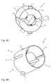
- FIGS. 3A and 3B show the mounting member 14, by means of which the sleeve 31 and thus the safety device 2 as a whole can be connected to the syringe body 1, wherein the FIG. 3A the mounting member 14 in a perspective view from above and the FIG. 3B shows the mounting member 14 in a perspective view from below.
- the mounting element 14 is present in the form of a substantially cylindrical shape with an outer diameter 45 and an inner diameter 46, wherein by the reference numeral 47, the distal end of the mounting member 14 is designated.
- two guide pins 5 are arranged on a lateral surface 48 of the mounting element 14 and lie opposite one another with respect to the mounting element 14. These guide pins 5 can then be arranged in the guide slot 6 of the sleeve and operatively connected thereto.
- the mounting member 14 has one or more, in this case two, recesses 49 and one or more, in the present case three, latching elements 50, whose functions are described below with reference to FIGS FIG. 3B being represented.
- FIG. 3B is denoted by the reference numeral 51, a proximal end 51 of the mounting member 14.
- the latching elements 50 of the mounting element 14 extend rising from the proximal end 51 to the distal end 47, ie the locking elements are seen at the distal end 47 in the radial direction greater than at the proximal end 51st
- the mounting element 14 is first pushed with its proximal end 51 onto the needle holder 28, the first half 52 becomes due to the thickness difference in the radial direction and rising in the axial direction and a second half 53 of the mounting member 14, which are separated by the recesses 49, moved away from each other. It is therefore necessary that the mounting member 14 is at least partially elastic.
- the first 52 and the second half 53 move towards one another through the elastic configuration, so that finally the mounting element 14 and thus the safety device 2 are clipped onto the syringe body 1.
- the latching elements 50 have at their distal end 50 'securing portions 50 ", which extend in the circumferential direction of an inner circle 54 of the mounting member 14 and are in mechanical operative contact with the transition region 30.
- the safety device 2 comprising the sleeve 31, the mounting member 14 and the cap member 21 is already pre-assembled and as a whole with the syringe body 1 by means of the mounting member 14 connectable.
- FIG. 4 shows a syringe body 1 with a safety device 2 mounted thereon in a longitudinal section.
- the safety device 2 comprises in addition to the cap member 21, the sleeve 31 and the mounting member 14, a spring element 17, which is presently designed as a coil spring 17.
- the guide pins 5 are in contact with the recess 4 or the guide slot 6, so that the guide pins are guided by the guide slot during a relative movement of the syringe body relative to the safety device.
- the mounting member 14 is clipped together with the narrowed portion 25 by means of the locking elements 50 and their securing portions 50 "and connected by means of the guide pins 5 with the sleeve 31.
- the sleeve 31 further comprises at its distal end 34 an inner bearing region 57, which is operatively connected to the spring element 17.
- the spring element 17 is therefore held on the one hand by the support area 57 and on the other hand by the mounting member 14 in the sleeve 31 and is secured against falling out.
- the dimensions of the safety device 2 are chosen such that the sleeve 31 has an inner diameter 55 which is greater than the diameter 23 of the syringe body 1, so that the syringe body 1 when moving in the longitudinal direction L forward, wherein the direction of movement is characterized by a Arrow L, opposite the safety device 2 of the syringe body is hineinbewegbar in the sleeve 31.
- the outer diameter 56 of the sleeve 31 or the safety device 2 is selected such that it corresponds at most to a maximum diameter of a holding device 58 attached to the proximal end of the syringe body 1 for holding and securely setting the syringe.
- the purpose of this size restriction is with reference to FIG. 6 shown in more detail.
- the safety device 2 is again presented in detail, in particular the movement of the guide pin 5 and the syringe body 1 relative to the safety device 2 and the position of the needle 3.
- the safety device 2 is in the Figures 5A-5E for clarity without cap member 21 and needle guard 22 shown.
- FIG. 5A the arrangement consisting of syringe body 1 and safety device 2 in an initial position 10 can be seen.
- a starting position 10 is understood to mean a syringe that has not yet been used.
- the guide pin 5 is also in a starting position 10 and is arranged in the first gate area 7.
- the first gate area 7 is separated from the second gate area 8 by the fictitious parting line 9 and the separating area 15, which has a vertex 16.
- the vertex 16 is here on the fictitious parting line 9.
- the first gate area 7 comprises a gate section 60, the second gate area 8 a second gate section 61.
- the second gate area 8 comprises a stop element 19.
- the first gate area 7 is in this case substantially I-shaped and comprises a curved first curve section 60, the second gate area 8 having an essentially L-shaped configuration with a second curved curve section 61, wherein the second curve section 61 consists of several parts.
- the distal end 34 of the sleeve is placed directly on the skin, so that the outlet opening 13 is in contact with the skin. If the syringe body 1 is now moved relative to the safety device 2 in the longitudinal direction L, then the guide pin 5 is guided through the first link section 60, whereby the mounting element 14 is moved around the narrowed region 25.
- the mounting member 14 is thus fixedly mounted in the axial direction, but can rotate freely in the radial direction around the constricted region 25 around.
- the guide pin 5 exceeds the fictitious parting line 9, then the guide pin 5 is transferred from the first gate area 7 into the second gate area 8, as in FIG. 5B or 5C is clearly visible.
- the distal end 12 of the lancing element 3 is arranged at the level of the outlet opening 13. The lancing element 3 is thus just about to emerge from the safety device 2, so that an injection is possible.
- the lancing element 3 can then be moved further out of the safety device 2 until the guide pin 5 has reached a distal end 63 of the second link area 8, thereby preventing further movement in the longitudinal direction.
- the user reduces the pressure on the syringe, whereby the syringe body 1 is moved counter to the longitudinal direction L by the spring force of the spring element 17.
- the puncturing element is thus automatically moved back into the safety device 2 by the spring element 17.
- the guide pin 5 moves here, depending on how far the lancing element 3 has been moved out, along the second link section 61 and / or on a line (not shown here) that runs parallel to the longitudinal direction.
- the second gate section is configured such that it, with the assistance of the return movement by the spring element 17, automatically transfers the guide pin into an end position 11 and is in contact with a stop element 19 in contact.
- the stop element 19 preferably comprises a vertex 20 which is arranged on the transverse line 64, which runs perpendicular to the parting line 9. The vertex 20 serves for better guidance of the guide pin 5 within the second gate area 8.
- the stop element further comprises a portion 65 on which the guide pin 5 rests.
- this section 65 is also on the transverse line 64, although other embodiments of the section 65 are conceivable.
- the section 65 may also have a curved path.
- the shape of the section 65 is always to be selected such that in an attempt to operate the syringe again, the guide pin 5 remains in its end position 11.
- FIG. 6 is referred to the FIG. 4 in which it has been described which dimension the safety device 2 should have advantageous. Also visible is a section of a syringe nest 66, the syringes each being suspended in an opening 67 of the syringe nest 66.
- the diameter 59 of the holding device is larger than the diameter 68 of an opening 67.
- the outer diameter 56 of the sleeve 31st or the outer diameter 56 of the safety device 2 may be selected to be smaller than the diameter 59 of the holding device 58. It is therefore possible to mount the syringe already with the safety device 2 in the syringe nest to fill and sterilize.
Abstract
Spritzenkörper mit einer endseitig angeordneten Sicherheitseinrichtung zur Vermeidung von Stichverletzungen, wobei der Spritzenkörper ein endseitig angeordnetes Stechelement umfasst und die Sicherheitseinrichtung eine Ausnehmung und mindestens einen Führungsstift aufweist, mittels welcher eine Führungskulisse ausgebildet ist, um den Führungsstift bei einer Relativbewegung von Spritzenkörper zu Sicherheitseinrichtung in einer Längsrichtung des Spritzenkörpers zu führen, wobei die Führungskulisse einen ersten und einen zweiten Kulissenbereich umfasst, die durch eine in einer Längsrichtung des Spritzenkörpers verlaufenden fiktiven Trennlinie voneinander getrennt sind,
wobei der Führungsstift in einer Ausgangsstellung in dem ersten Kulissenbereich anordenbar ist und von dem ersten in den zweiten Kulissenbereich in eine Endstellung durch Überschreiten der Trennlinie überführbar ist, wenn ein distales Ende des Stechelements bei der Relativbewegung von Spritzenkörper zu Sicherheitseinrichtung auf der Höhe einer Austrittsöffnung der Sicherheitseinrichtung angeordnet ist.

wherein the guide pin can be arranged in a starting position in the first gate area and can be transferred from the first to the second gate area in an end position by exceeding the dividing line, when a distal end of the lancing element in the relative movement of the syringe body to safety device at the height of an outlet opening of the safety device is arranged.
Description
Die Erfindung betrifft einen Spritzenkörper mit einer endseitig angeordneten Sicherheitseinrichtung zur Vermeidung von Stichverletzungen, wobei der Spritzenkörper ein endseitig angeordnetes Stechelement umfasst und die Sicherheitseinrichtung mindestens einen Führungsstift und eine Ausnehmung und aufweist, mittels welcher eine Führungskulisse ausgebildet ist, um den Führungsstift bei einer Relativbewegung von Spritzenkörper zu Sicherheitseinrichtung in einer Längsrichtung des Spritzenkörpers zu führen.The invention relates to a syringe body with an end arranged safety device to avoid puncture injuries, wherein the syringe body comprises an end arranged lancing element and the safety device at least one guide pin and a recess and, by means of which a guide slot is formed to the guide pin in a relative movement of the syringe body to guide safety device in a longitudinal direction of the syringe body.
Aus dem Stand der Technik sind bisher Sicherheitseinrichtungen zur Vermeidung von Stichverletzungen bekannt, die nach einem Befüllen der Spritzen um die gesamte Spritze herum montiert werden.From the state of the art safety devices for preventing puncture injuries have hitherto been known which are mounted around the entire syringe after the syringes have been filled.
Diese Sicherheitsvorrichtungen vergrößern jedoch die Dimension, sowohl in der reinen Größe als auch dem Gewicht, der Spritze zum Gebrauch, so dass eine Handhabung von Spritzen mit derartigen Sicherheitsvorrichtungen erheblich erschwert wird.However, these safety devices increase the size, both in pure size and weight, of the syringe for use, thus making handling syringes with such safety devices significantly more difficult.
Darüber hinaus sind Sicherheitseinrichtung derart konstruiert, dass eine Spritze bereits unbrauchbar gemacht werden kann, beispielsweise bei einem Abbruch der Injektion, ohne dass die Nadelspitze überhaupt aus der Sicherheitseinrichtung herausgetreten ist. Die Spritze ist also bereits unbrauchbar, bevor sie überhaupt Kontakt mit dem Patienten hatte und eigentlich noch gar nicht verunreinigt worden ist.In addition, safety devices are designed so that a syringe can already be made unusable, for example, at a termination of the injection, without the needle tip has ever emerged from the safety device. The syringe is Already useless before she had any contact with the patient and was not actually contaminated.
Andere bekannte Sicherheitseinrichtung geben den umgekehrten Fall wider. Die Nadelspitze wird erst dann in eine sichere Stellung überführt, wenn die Nadelspitze bereits aus der Sicherheitseinrichtung ausgetreten ist. Dies hat den gravierenden Nachteil, dass eine Injektion wiederholt werden könnte, obwohl die Nadel bereits mit dem Patienten in Kontakt war. Es ist daher möglich, dass jemand mit einer verunreinigten Spritze in Kontakt kommen kann und sich daran verletzen oder sogar infizieren kann.Other known safety devices give the opposite case. The needle tip is only transferred to a safe position when the needle tip has already leaked out of the safety device. This has the serious disadvantage that an injection could be repeated even though the needle was already in contact with the patient. It is therefore possible that someone may come into contact with a contaminated syringe and injure or even become infected.
Es ist daher die Aufgabe der vorliegenden Anmeldung, einen Spritzenkörper mit einer Sicherheitsvorrichtung bereitzustellen, die die Nachteile des Standes der Technik nicht mehr aufweist.It is therefore the object of the present application to provide a syringe body with a safety device, which no longer has the disadvantages of the prior art.
Gelöst wird diese zugrunde liegende Aufgabe von einem Spritzenkörper mit einer endseitig angeordneten Sicherheitseinrichtung zur Vermeidung von Stichverletzungen, wobei der Spritzenkörper ein endseitig angeordnetes Stechelement umfasst und die Sicherheitseinrichtung zumindest eine Ausnehmung und mindestens einen Führungsstift aufweist, wobei mittels der Ausnehmung eine Führungskulisse ausgebildet ist, um den Führungsstift bei einer Relativbewegung von Spritzenkörper zu Sicherheitseinrichtung in einer Längsrichtung des Spritzenkörpers zu führen, wobei die Führungskulisse einen ersten und einen zweiten Kulissenbereich umfasst, die durch eine in einer Längsrichtung des Spritzenkörpers verlaufenden fiktiven Trennlinie voneinander getrennt sind und wobei der Führungsstift in einer Ausgangsstellung in dem ersten Kulissenbereich anordenbar ist und von dem ersten in den zweiten Kulissenbereich in eine Endstellung durch Überschreiten der Trennlinie überführbar ist, wenn ein distales Ende des Stechelements bei der Relativbewegung von Spritzenkörper zu Sicherheitseinrichtung auf der Höhe einer Austrittsöffnung der Sicherheitseinrichtung angeordnet ist.This underlying object is achieved by a syringe body with an end arranged safety device to avoid puncture injuries, wherein the syringe body comprises an end arranged lancing element and the safety device has at least one recess and at least one guide pin, wherein by means of the recess a guide slot is formed to the Guide pin during a relative movement of the syringe body to run safety device in a longitudinal direction of the syringe body, wherein the guide slot comprises a first and a second link area, which are separated by a running in a longitudinal direction of the syringe body fictitious parting line and wherein the guide pin in a starting position in the first gate area is arranged and can be converted from the first to the second gate area in an end position by crossing the dividing line, when a dis Tales end of the piercing element is arranged in the relative movement of the syringe body to safety device at the height of an outlet opening of the safety device.
Der Begriff "endseitig angeordnet" ist in diesem Zusammenhang derart zu verstehen, dass das jeweilige bauliche Element auf einem distalen Ende angeordnet ist. So sind die Sicherheitseinrichtung sowie das Stechelement an dem distalen Ende des Spritzenkörpers angeordnet.The term "arranged at the end" is to be understood in this context such that the respective structural element is arranged on a distal end. Thus, the safety device and the piercing element are arranged at the distal end of the syringe body.
Unter dem Begriff "Stechelement" ist eine Nadel, eine Kanüle, eine Lanzette oder dergleichen zu verstehen.The term "piercing element" is to be understood as meaning a needle, a cannula, a lancet or the like.
Unter einer "Ausgangstellung" wird eine Stellung, vorzugsweise des Führungsstiftes, beschrieben, die einer unbenutzten Spritze entspricht, also vor dem Gebrauch einer Spritze.A "starting position" describes a position, preferably of the guide pin, which corresponds to an unused syringe, that is to say prior to the use of a syringe.
Unter einer "Endstellung" wird eine Stellung beschrieben, in der die vorliegende Spritze bereits benutzt wurde. Hat der Führungsstift die Endstellung erreicht, so ist es nicht mehr möglich, die Spritze noch einmal zu verwenden.An "end position" describes a position in which the present syringe has already been used. If the guide pin has reached the end position, it is no longer possible to use the syringe again.
Erfindungsgemäß ist der Führungsstift von dem ersten Kulissenbereich in den zweiten Kulissenbereich überführbar. Diese Überführung findet statt, wenn der Führungsstift eine fiktive Trennlinie, die den ersten und den zweiten Kulissenbereich voneinander trennt, überschreitet. Befindet sich der Führungsstift in dem ersten Kulissenbereich, also in einer Ausgangsstellung, so wurde die Spritze noch nicht ausgelöst, d.h. die Nadel hat die Sicherheitseinrichtung noch nicht verlassen. Befindet sich der Führungsstift in dem zweiten Kulissenbereich, so ist die Nadel aus der Sicherheitseinrichtung bereits ausgetreten, so dass eine Injektion möglich ist. Beim Übergang von dem ersten Kulissenbereich zu dem zweiten Kulissenbereich, also genau dann, wenn der Führungsstift die Trennlinie überschreitet, befindet sich das distale Ende des Stechelements, beispielsweise der Nadel, auf der Höhe der Austrittsöffnung der Sicherheitseinrichtung.According to the invention, the guide pin can be transferred from the first gate area into the second gate area. This transition takes place when the guide pin exceeds a fictitious parting line separating the first and second gate sections. If the guide pin is in the first gate area, ie in a starting position, the syringe has not yet been triggered, i. the needle has not yet left the safety device. If the guide pin is in the second gate area, then the needle has already left the safety device, so that an injection is possible. During the transition from the first gate area to the second gate area, ie precisely when the guide pin exceeds the parting line, the distal end of the piercing element, for example the needle, is at the height of the exit opening of the safety device.
Gemäß einer besonders bevorzugten Ausführungsform umfasst die Sicherheitseinrichtung mindestens ein Federelement. Das Federelement ist vorzugsweise mit dem Spritzenkörper wirkverbunden und wirkt der Relativbewegung des Spritzenköpers gegenüber der Sicherheitseinrichtung entgegen. Dies bedeutet, dass wenn ein Benutzer der Spritze den Spritzenkörper gegenüber der Sicherheitseinrichtung bewegt, so wirkt das Federelement entgegen und würde, falls die Relativbewegung unterbunden wird, den Spritzenkörper bezüglich der Sicherheitseinrichtung wieder in eine Position zurückführen, in der sich die Spritze wieder vollständig in der Sicherheitseinrichtung befindet.According to a particularly preferred embodiment, the safety device comprises at least one spring element. The spring element is preferably operatively connected to the syringe body and counteracts the relative movement of the syringe body with respect to the safety device. This means that when a user of the syringe moves the syringe body with respect to the safety device, the spring element counteracts and, if the relative movement is suppressed, the syringe body with respect to the safety device back to a position in which the syringe completely in the Safety device is located.
Durch das Federelement kann also gewährleistet werden, dass die Nadel nach Gebrauch der Spritze sicher in die Sicherheitseinrichtung rückgeführt werden kann und der Führungsstift in die Endstellung vorzugsweise automatisch überführt werden kann.By the spring element can thus be ensured that the needle after use of the syringe can be safely returned to the safety device and the guide pin can be preferably automatically transferred to the end position.
Dabei kann das Federelement auf verschiedene Weisen ausgestaltet sein. Vorzugsweise handelt es sich bei dem Federelement um eine Spiralfeder.In this case, the spring element can be configured in various ways. Preferably, the spring element is a spiral spring.
Gemäß einer bevorzugten Ausführungsform ist die Sicherheitseinrichtung mittels eines Montageelements mit dem Spritzenkörper zumindest wirkverbunden. Es ist dabei denkbar, dass der Führungsstift/die Führungsstifte auf dem Montagelement angeordnet sind. Dabei ist vorteilhaft das Montageelement einerseits mit einem Nadelaufsatz, der mit dem Spritzenkörper verbunden ist, verbunden und andererseits mittels des zumindest einen Führungsstifts mit der Sicherheitseinrichtung verbunden, da der Führungsstift innerhalb der Führungskulisse der Sicherheitseinrichtung angeordnet ist.According to a preferred embodiment, the safety device is at least operatively connected to the syringe body by means of a mounting element. It is conceivable that the guide pin / pins are arranged on the mounting element. In this case, the mounting element is advantageously connected on the one hand to a needle attachment which is connected to the syringe body and on the other hand to the safety device by means of the at least one guide pin, since the guide pin is arranged within the guide slot of the safety device.
Besonders vorteilhaft ist das Montageelement innerhalb einer Hülse der Sicherheitseinrichtung angeordnet. Weiter vorteilhaft weist eben diese Hülse auch die Führungskulisse auf.Particularly advantageously, the mounting element is arranged within a sleeve of the safety device. Further advantageously, just this sleeve also has the guide link.
Gemäß einer bevorzugten Ausführungsform umfasst die Sicherheitseinrichtung, insbesondere die Hülse, zwei Ausnehmungen, und das Montageelement zwei Führungsstifte, wobei die Ausnehmungen und die Führungsstifte vorteilhaft gegenüberliegend ausgebildet sind, wodurch eine besonders vorteilhafte Führung gewährleistet werden kann.According to a preferred embodiment, the safety device, in particular the sleeve, two recesses, and the mounting element comprises two guide pins, wherein the recesses and the guide pins are advantageously formed opposite, whereby a particularly advantageous guidance can be ensured.
Weiter bevorzugt ist das Federelement ebenso innerhalb der Hülse angeordnet und besonders bevorzugt mittels des Montageelements in der Hülse gegen ein Herausfallen gesichert.More preferably, the spring element is also disposed within the sleeve and more preferably secured by means of the mounting member in the sleeve against falling out.
Vorteilhaft weist der erste Kulissenbereich einen ersten kurvenförmigen Kulissenabschnitt und der zweite Kulissenbereich einen zweiten kurvenförmigen Kulissenabschnitt auf, an denen der Führungsstift, je nach Position in der Führungskulisse, geführt wird. Vorteilhaft kann der jeweilige Kulissenabschnitt mehrere Teilabschnitte aufweisen.Advantageously, the first gate area has a first curved gate section and the second gate area has a second curved gate section, on which the guide pin is guided, depending on the position in the guide slot. Advantageously, the respective gate section may have a plurality of sections.
Da die Kulissenbereiche kurvenförmige Kulissenabschnitte aufweisen können, ist es vorteilhaft, wenn das Montageelement, wenn es auf dem Spritzenkörper montiert ist, axial nicht mehr verschoben kann, sich jedoch radial um den Spritzenkörper drehen kann. Dies gewährleistet, dass der Führungsstift dem Verlauf der jeweiligen Kulisse folgen kann. Dies bedeutet also, dass bei einer Relativbewegung das Montageelement und demzufolge auch der Führungsstift sich um den Spritzenkörper drehen können.Since the gate areas may have curved gate sections, it is advantageous if the mounting element, when it is mounted on the syringe body, can not be axially displaced, but can rotate radially around the syringe body. This ensures that the guide pin can follow the course of the respective backdrop. This means that in a relative movement, the mounting element and consequently also the guide pin can rotate around the syringe body.
Gemäß einer weiter bevorzugten Ausführungsform ist vorgesehen, dass an dem ersten sowie dem zweiten Kulissenbereich ein Trennbereich angrenzt. Weiter vorteilhaft ist dieser Trennbereich zumindest teilweise zwischen dem ersten und dem zweiten Kulissenbereich anordenbar.According to a further preferred embodiment, provision is made for a separation area to adjoin the first and the second gate area. Further advantageously, this separation region can be arranged at least partially between the first and the second gate area.
Besonders bevorzugt ist der Trennbereich derart ausgestaltet, dass der Trennbereich einen Scheitelpunkt aufweist, der auf der fiktiven Trennlinie. Vorteilhaft handelt es sich bei diesem Scheitelpunkt um ein lokales Extremum des Trennbereichs, so dass hierdurch eine Bewegung des Führungsstiftes unterstützt werden kann. Dadurch, dass der Scheitelpunkt auf der Trennlinie liegt, kann der erste als auch der zweite Kulissenbereich mittels des Trennbereichs und der Trennlinie gut bestimmt werden. Außerdem wird dadurch, dass es sich bei dem Scheitelpunkt vorzugsweise um ein lokales Extremum handelt, die Führung des Führungsstifts, insbesondere entgegen der Längsrichtung des Spritzenkörpers, geführt, da der Scheitelpunkt im Bereich um den Scheitelpunkt herum bestimmt, in welchen Kulissenbereich der Führungsstift geführt wird.Particularly preferably, the separation region is designed such that the separation region has a vertex that is on the fictitious separation line. Advantageously, this vertex is a local extremum of the separation area, so that in this way a movement of the guide pin can be supported. The fact that the vertex lies on the dividing line, the first and the second gate area can be well determined by means of the separation area and the dividing line. In addition, because the apex is preferably a local extremum, the guidance of the guide pin is guided, in particular against the longitudinal direction of the syringe body, since the vertex in the region around the vertex determines in which gate region the guide pin is guided.
Gemäß einer besonders bevorzugten Ausführungsform ist, wenn der Führungsstift sich in dem zweiten Kulissenbereich befindet, der Führungsstift mittels einer Kulisse des zweiten Kulissenbereichs in einen Endbereich überführbar. Vorzugsweise ist in diesem Endbereich der Führungsstift mit einem Stoppelement wirkverbindbar.According to a particularly preferred embodiment, when the guide pin is located in the second gate area, the guide pin can be converted into an end area by means of a gate of the second gate area. Preferably, in this end region of the guide pin with a stop member operatively connected.
Vorteilhaft handelt es sich bei der Kulisse des zweiten Kulissenbereichs um den zweiten Kulissenabschnitt.Advantageously, the backdrop of the second gate area is the second gate section.
Dies bedeutet also, wenn sich der Führungsstift im zweiten Kulissenbereich befindet, wird der Führungsstift mittels dem zweiten Kulissenbereichs und vorzugsweise mit Hilfe des Federelements in den Endbereich überführt und ist dann mit dem Stoppelement wirkverbunden.This means that when the guide pin is in the second gate area, the guide pin is transferred by means of the second gate area and preferably by means of the spring element in the end region and is then operatively connected to the stop element.
Das Stoppelement ist dabei derart ausgestaltet, dass, wenn sich der Führungsstift in der Endstellung befindet, sich der Führungsstift nicht mehr in Längsrichtung zum distalen Ende der Nadel hin bewegen lässt, wodurch ein weiteres Herausbringen der Nadel aus der Sicherheitseinrichtung unterbunden wird.The stop element is designed such that when the guide pin is in the end position, the guide pin can no longer be moved in the longitudinal direction to the distal end of the needle, whereby further removal of the needle is prevented from the safety device.
Gemäß einer bevorzugten Ausführungsform umfasst daher das Stoppelement einen Scheitel, der auf einer Linie liegt, die senkrecht zu der Trennlinie angeordnet ist. Dies bedeutet, dass sich die Linie in eine Breitenrichtung des Spritzenkörpers erstreckt. Die Linie kann auch als Querlinie bezeichnet werden. Besonders vorteilhaft erstreckt sich ebenso das Stoppelement mit dem Scheitel in Richtung dieser Querlinie. Dies bedeutet, dass das Stoppelement im Wesentlichen in einem Winkel von 90°zu dem Tren nbereich angeordnet ist.According to a preferred embodiment, therefore, the stop element comprises a vertex which lies on a line which is arranged perpendicular to the parting line. This means, that the line extends in a width direction of the syringe body. The line can also be referred to as a transverse line. Particularly advantageously, the stop element also extends with the apex in the direction of this transverse line. This means that the stop element is arranged substantially at an angle of 90 ° to the Tren nbereich.
Durch die Anordnung eines solchen Stoppelements ist es also möglich, dass eine bereits benutze Spritze, also eine Spritze, dessen Stechelement bereits aus der Sicherheitseinrichtung herausgetreten ist, nicht noch einmal für einen Injektionsvorgang verwendet werden kann. Ebenso kann ein Patient oder ein Drittbenutzer sich vor und nach dem Injektionsvorgang nicht mehr an dem Stechelement verletzen, da das Stechelement jeweils von der Sicherheitseinrichtung umschlossen wird.By arranging such a stop element, it is thus possible for an already used syringe, that is to say a syringe whose puncturing element has already emerged from the safety device, not to be used again for an injection procedure. Likewise, a patient or a third party user can not injure themselves on the puncturing element before and after the injection process, since the lancing element is enclosed in each case by the safety device.
Gemäß einer bevorzugten Ausführungsform ist es daher auch denkbar, dass zusätzlich zu der bisher beschriebenen Sicherheitseinrichtung die Sicherheitseinrichtung ein Kappenelement und/oder einen Nadelschutz umfasst. Vorteilhaft ist das Kappenelement mit dem Nadelschutz ausgestattet. Weiter vorteilhaft ist das Kappenelement vor Gebrauch der Spritze von der Sicherheitseinrichtung abnehmbar, wodurch auch gegebenenfalls der Nadelschutz mit abgenommen werden kann. Somit kann für einen Benutzer der Spritze die Sicherheit der Sicherheitseinrichtung noch weiter erhöht werden, so dass die Gefahr einer Verletzung noch weiter minimiert werden kann.According to a preferred embodiment, it is therefore also conceivable that in addition to the previously described safety device, the safety device comprises a cap member and / or a needle guard. Advantageously, the cap member is equipped with the needle guard. Further advantageously, the cap member before use of the syringe from the safety device is removable, whereby also, if necessary, the needle guard can be removed with. Thus, for a user of the syringe, the safety of the safety device can be further increased, so that the risk of injury can be further minimized.
Weitere vorteilhafte Ausführungsformen ergeben sich aus den Unteransprüchen.Further advantageous embodiments will become apparent from the dependent claims.
Weitere Ziele, Vorteile und Zweckmäßigkeiten der vorliegenden Erfindung sind der nachfolgenden von der Beschreibung in Verbindung mit der Zeichnung zu entnehmen. Hierbei zeigen:
- Fig. 1
- einen Ausschnitt des Spritzenkörpers;
- Fig. 2A
- eine perspektivische Ansicht der Hülse;
- Fig. 2B
- eine perspektivische Ansicht des Kappenelements;
- Fig. 3A
- eine perspektivische Ansicht des Montageelements von oben;
- Fig. 3B
- eine perspektivische Ansicht des Montageelement von unten;
- Fig. 4
- einen Spritzenkörper mit darauf montierten Sicherheitseinrichtung in einem Längsschnitt;
- Fig. 5A
- eine Spritze in der Ausgangsstellung;
- Fig. 5B
- die Spritze gemäß
Figur 5A im Moment der Überführung; - Fig. 5C
- die Spritze gemäß
Figur 5A im Moment der Überführung mit einem Längsschnitt - Fig. 5D
- die Spritze gemäß
Figur 5A in der Endstellung - Fig. 5E
- die Spritze gemäß
Figur 5A in der Endstellung mit einem Längsschnitt - Fig. 6
- eine in ein Spritzennest eingehängte Spritze umfassend Spritzenkörper und Sicherheitseinrichtung
- Fig. 1
- a section of the syringe body;
- Fig. 2A
- a perspective view of the sleeve;
- Fig. 2B
- a perspective view of the cap member;
- Fig. 3A
- a perspective view of the mounting member from above;
- Fig. 3B
- a perspective view of the mounting element from below;
- Fig. 4
- a syringe body with safety device mounted thereon in a longitudinal section;
- Fig. 5A
- a syringe in the starting position;
- Fig. 5B
- the syringe according to
FIG. 5A at the moment of the transfer; - Fig. 5C
- the syringe according to
FIG. 5A at the moment of transfer with a longitudinal section - Fig. 5D
- the syringe according to
FIG. 5A in the final position - Fig. 5E
- the syringe according to
FIG. 5A in the end position with a longitudinal section - Fig. 6
- a syringe suspended in a syringe nest comprising syringe body and safety device
Weiter ist vorliegend an dem distalen Ende 27 des verengten Bereichs 25 eine Nadelhalterung 28 mit einem Stechelement 3, vorliegend einer Nadel 3, angeordnet, wobei diese Nadelhalterung 28 einen Durchmesser 29 aufweist, der größer ist als der Durchmesser 26 des verengten Bereichs 25, jedoch kleiner ist als der Durchmesser 23 des Spritzenkörpers 1. Weiter ist die Nadelhalterung 28 an dem distalen Ende 27 des verengten Bereichs 25 angeordnet, so dass ein Übergangsbereich 30 entsteht, wobei durch den Übergangsbereich 30 ein Bereich ausgebildet ist, an dem einerseits der Durchmesser 26 des verengten Bereichs 25 und der Durchmesser 29 der Nadelhalterung aufeinandertreffen und so der Durchmesser an sich sprunghaft verändert wird. Durch den Übergangsbereich 30 ist demnach eine Art Vorsprung ausgebildet.Further, in the present case at the
In der
Der Ausnahmebereich 32 dient vorliegend dazu, dass ein Kappenelement 21 (siehe
An dem distalen Ende 34 der Hülse 31 weist die Hülse vorzugsweise eine Austrittsöffnung 13 auf, die vorliegend als ein Kreisring 35 ausgebildet ist, wobei an dem Kreisring 35 anschließend die Hülse 31 mit einem ringförmigen Bereich 36 fortgesetzt wird. Vorliegend weist der ringförmige Bereich 36 einen größeren Durchmesser als der Kreisring 35 auf. Besonders vorteilhaft sind der Kreisring 35 und der ringförmige Bereich 36 konzentrisch zueinander angeordnet. Vorteilhaft ist das Kappenelement 21 derart ausgestaltet, dass es auf den Kreisring 35 aufsetzbar ist, aber nicht auf dem ringförmigen Bereich 36, so dass bei einem Aufsetzen des Kappenelements 21 das Kappenelement 21 sowohl mit dem Kreisring 35 als auch mit dem ringförmigen Bereich 36 in Kontakt steht und die Aufsetzbewegung des Kappenelements 21 durch diese Ausgestaltung limitiert wird.At the
Der
Der Nadelschutz 22 ist vorzugsweise im Wesentlichen zylindrisch ausgestaltet und ist vorteilhaft mit dem Kappenelement 21 fest verbindbar bzw. verbunden, wobei der Nadelschutz 22 vorzugsweise derart ausgestaltet ist, dass der Nadelschutz 22 in den Kreisring 35 hineinsteckbar ist. Dies bedeutet also, dass ein Außendurchmesser 40 (hier nicht gezeigt) des Nadelschutzes 22 höchstens dem Innendurchmesser 39 des Kreisrings 35 entspricht. Es ist jedoch vorstellbar, dass andere geometrische Formen anstelle eines Kreises verwendet werden.The
Das distale Ende 38 des Kappenelements 21 ist vorliegend ebenfalls als ein Kreisring 41 ausgestaltet, dessen Innendurchmesser 43 mindestens dem Außendurchmesser 42 des Kreisrings 35 und höchstens dem Außendurchmesser 43 des ringförmigen Bereichs 36 entspricht. Dies bedeutet, dass der Kreisring 41 auf dem ringförmigen Bereich zu liegen kommt und somit miteinander wirkverbunden sind.In the present case, the
Die
Das Montageelement 14 ist vorliegend im Wesentlichen eine zylindrische Form mit einem Außendurchmesser 45 und einem Innendurchmesser 46 auf, wobei durch das Bezugszeichen 47 das distale Ende des Montageelements 14 bezeichnet ist.The mounting
Vorliegend sind auf einer Mantelfläche 48 des Montageelements 14 zwei Führungsstifte 5 angeordnet, die sich bezüglich des Montageelements 14 gegenüber liegen. Diese Führungsstifte 5 sind dann in der Führungskulisse 6 der Hülse anordenbar und mit dieser wirkverbindbar.In the present case, two
Zusätzlich weist das Montageelement 14 eine oder mehrere, vorliegend zwei, Aussparungen 49 und ein oder mehrere, vorliegend drei, Rastelemente 50 auf, deren Funktionen nachstehend mit Bezug auf die
In der
Wird beim Zusammenfügen des Montageelements 14 mit dem Spritzenkörper 1, insbesondere mit dem verengten Bereich 25, das Montageelement 14 mit seinem proximalen Ende 51 zuerst auf die Nadelhalterung 28 geschoben, so wird durch den Dickenunterschied in radialer Richtung und ansteigend in axialer Richtung eine erste Hälfte 52 und eine zweite Hälfte 53 des Montageelements 14, die durch die Aussparungen 49 getrennt sind, voneinander wegbewegt. Es ist hierbei also erforderlich, dass das Montageelement 14 zumindest teilweise elastisch ausgebildet ist.If, during assembly of the
Passiert das distale Ende 47 des Montageelements 14 den Übergangsbereich 30, so bewegen sich die erste 52 und die zweite Hälfte 53 durch die elastische Ausgestaltung aufeinander zu, so dass schlussendlich das Montageelement 14 und somit die Sicherheitseinrichtung 2 auf dem Spritzenkörper 1 aufgeclipst ist.If the
Zur Sicherung dieser Clipverbindung weisen die Rastelemente 50 an ihrem distalen Ende 50' Sicherungsabschnitte 50" auf, die sich in Umfangsrichtung eines Innenkreises 54 des Montageelements 14 erstrecken und mit dem Übergangsbereich 30 in mechanischen Wirkkontakt stehen.To secure this clip connection, the latching
Besonders bevorzugt ist die Sicherheitseinrichtung 2 umfassend die Hülse 31, das Montageelement 14 und das Kappenelement 21 bereits vormontierbar und als Ganzes mit dem Spritzenkörper 1 mittels des Montageelements 14 verbindbar.Particularly preferably, the
Die
Die Sicherheitseinrichtung 2 umfasst dabei zusätzlich zu dem Kappenelement 21, der Hülse 31 und dem Montageelement 14 ein Federelement 17, das vorliegend als eine Spiralfeder 17 ausgebildet ist.The
Wie deutlich zu erkennen ist, stehen die Führungsstifte 5 mit der Ausnehmung 4 bzw. der Führungskulisse 6 in Kontakt, so dass die Führungsstifte durch die Führungskulisse bei einer Relativbewegung des Spritzenkörpers gegenüber der Sicherheitseinrichtung geführt werden. Das Montageelement 14 ist mit dem verengten Bereich 25 mittels der Rastelemente 50 und deren Sicherungsabschnitte 50" miteinander verclipst und mittels der Führungsstifte 5 mit der Hülse 31 verbunden.As can be clearly seen, the guide pins 5 are in contact with the recess 4 or the guide slot 6, so that the guide pins are guided by the guide slot during a relative movement of the syringe body relative to the safety device. The mounting
Die Hülse 31 umfasst weiter an seinem distalen Ende 34 einen innenliegenden Auflagebereich 57, der mit dem Federelement 17 wirkverbindbar ist. Das Federelement 17 wird also einerseits durch den Auflagebereich 57 und andererseits durch das Montageelement 14 in der Hülse 31 gehalten und ist so gegen ein Herausfallen gesichert.The
Die Dimensionen der Sicherheitseinrichtung 2 sind derart gewählt, dass die Hülse 31 einen Innendurchmesser 55 aufweist, der größer ist als der Durchmesser 23 des Spritzenkörpers 1, so dass der Spritzenkörper 1 bei einer Bewegung in Längsrichtung L nach vorne, wobei die Bewegungsrichtung gekennzeichnet ist durch einen Pfeil L, gegenüber der Sicherheitseinrichtung 2 der Spritzenkörper in die Hülse 31 hineinbewegbar ist. Gleichzeitig ist der Außendurchmesser 56 der Hülse 31 bzw. der Sicherheitseinrichtung 2 so gewählt, dass er höchstens einem maximalen Durchmesser einer am proximalen Ende des Spritzenkörpers 1 angebrachten Haltevorrichtung 58 zum Halten und sicheren Setzen der Spritze entspricht. Der Zweck dieser Größeneinschränkung wir mit Bezug auf
Mit Bezug auf die
In der
Der Führungsstift 5 befindet sich ebenso in einer Ausgangsstellung 10 und ist in dem ersten Kulissenbereich 7 angeordnet. Der erste Kulissenbereich 7 wird von dem zweiten Kulissenbereich 8 durch die fiktive Trennlinie 9 und dem Trennbereich 15, der einen Scheitelpunkt 16 aufweist, getrennt. Der Scheitelpunkt 16 liegt hierbei auf der fiktiven Trennlinie 9. Der erste Kulissenbereich 7 umfasst einen Kulissenabschnitt 60, der zweite Kulissenbereich 8 einen zweiten Kulissenabschnitt 61. Ferner umfasst der zweiten Kulissenbereich 8 ein Stoppelement 19.The
Der erste Kulissenbereich 7 ist hierbei im Wesentlichen I-förmig ausgebildet und umfasst einen kurvenförmigen ersten Kurvenabschnitt 60, wobei der zweite Kulissenbereich 8 im Wesentlichen eine L-förmige Gestalt aufweist mit einem zweiten kurvenförmigen Kurvenabschnitt 61, wobei der zweite Kurvenabschnitt 61 aus mehreren Teilen besteht.The
Vorzugsweise wird das distale Ende 34 der Hülse direkt auf die Haut aufgesetzt, so dass die Austrittsöffnung 13 mit der Haut in Kontakt steht. Wird der Spritzenkörper 1 nun relativ zu der Sicherheitseinrichtung 2 in Längsrichtung L bewegt, so wird der Führungsstift 5 durch den ersten Kulissenabschnitt 60 geführt, wodurch das Montageelement 14 um den verengten Bereich 25 herum bewegt wird. Das Montageelement 14 ist also in axialer Richtung fest montiert, kann sich aber in radialer Richtung um den verengten Bereich 25 herum frei drehen.Preferably, the
Überschreitet der Führungsstift 5 die fiktive Trennlinie 9, so wird der Führungsstift 5 von dem ersten Kulissenbereich 7 in den zweiten Kulissenbereich 8 überführt, wie in der
Das Stechelement 3 kann dann weiter aus der Sicherheitseinrichtung 2 herausbewegt werden, solange bis der Führungsstift 5 ein distales Ende 63 des zweiten Kulissenbereichs 8 erreicht hat und dadurch eine weitere Bewegung in Längsrichtung verhindert wird.The lancing
Wurde die Injektion durchgeführt bzw. das Stechelement 3 aus der Sicherheitseinrichtung 2 herausbewegt, so vermindert der Benutzer den Druck auf die Spritze, wodurch durch die Federkraft des Federelements 17 der Spritzenköper 1 gegenüber der Sicherheitseinrichtung 2 entgegen der Längsrichtung L bewegt wird. Das Stechelement wird also durch das Federelement 17 automatisch in die Sicherheitseinrichtung 2 zurückbewegt. Der Führungsstift 5 bewegt sich hierbei, je nachdem wie weit das Stechelement 3 herausbewegt wurde, entlang des zweiten Kulissenabschnitts 61 und/oder auf einer Linie (hier nicht gezeigt), die parallel zur Längsrichtung verläuft.If the injection has been carried out or the lancing
Ab einer gewissen Position des Führungsstifts 5 im zweiten Kulissenbereich 8 ist der Führungsstift 5 mit dem zweiten Kulissenabschnitt 61 in Kontakt und wird von diesem geführt. Der zweite Kulissenabschnitt ist derart ausgestaltet, dass er, mit Unterstützung der Rückführbewegung durch das Federelement 17, den Führungsstift automatisch in eine Endstellung 11 überführt und steht in Kontakt mit einem Stoppelement 19 in Kontakt. Das Stoppelement 19 umfasst vorzugsweise einen Scheitel 20, der auf der Querlinie 64, die senkrecht zur Trennlinie 9 verläuft, angeordnet ist. Der Scheitel 20 dient zur besseren Führung des Führungsstifts 5 innerhalb des zweiten Kulissenbereichs 8. Vorliegend umfasst das Stoppelement weiter einen Abschnitt 65, an dem der Führungsstift 5 anliegt. Vorliegend liegt dieser Abschnitt 65 ebenso auf der Querlinie 64, wobei jedoch auch andere Ausgestaltungen des Abschnitts 65 denkbar sind. Beispielsweise kann der Abschnitt 65 auch eine Kurvenbahn aufweisen.From a certain position of the
Dabei ist die Form des Abschnitts 65 immer derart zu wählen, dass bei einem Versuch, die Spritze erneut zu betätigen, der Führungsstift 5 in seiner Endstellung 11 verbleibt.The shape of the
In der
Sämtliche in den Anmeldungsunterlagen offenbarten Merkmale werden als erfindungswesentlich beansprucht, sofern sie einzeln oder in Kombination gegenüber dem Stand der Technik neu sind.All disclosed in the application documents features are claimed as essential to the invention, provided they are new individually or in combination over the prior art.
- 11
- Spritzenkörpersyringe body
- 22
- Sicherheitseinrichtungsafety device
- 33
- Stechelementpiercing member
- 44
- Ausnehmungrecess
- 4'4 '
- spiegelbildliche Ausnehmungmirror image recess
- 55
- Führungsstiftguide pin
- 66
- Führungskulisseguide link
- 77
- erster Kulissenbereichfirst backdrop area
- 88th
- zweiter Kulissenbereichsecond backdrop area
- 99
- fiktive Trennliniefictional dividing line
- 1010
- Ausgangstellungstarting position
- 1111
- Endstellungend position
- 1212
- distales Ende des Stechelementsdistal end of the lancing element
- 1313
- Austrittsöffnungoutlet opening
- 1414
- Montageelementmounting element
- 1515
- Trennbereichseparating region
- 1616
- Scheitelpunkt des TrennbereichsVertex of the separation area
- 1717
- Federelementspring element
- 1818
- Kulisse des zweiten KulissenbereichsBackdrop of the second set of scenes
- 1919
- Stoppelementstop element
- 2020
- Scheitel des StoppelementsVertex of the stoppage
- 2121
- Kappenelementcap member
- 2222
- Nadelschutzneedle guard
- 2323
- Durchmesser des SpritzenkörpersDiameter of the syringe body
- 2424
- distales Ende des Spritzenkörpersdistal end of the syringe body
- 2525
- verengter Bereich des Spritzenkörpersnarrowed area of the syringe body
- 2626
- Durchmesser des verengten BereichsDiameter of the narrowed area
- 2727
- distales Ende des verengten Bereichsdistal end of the narrowed area
- 2828
- Nadelhalterungneedle holder
- 2929
- Durchmesser NadelhalterungDiameter needle holder
- 3030
- ÜbergangsbereichTransition area
- 3131
- Hülseshell
- 3232
- Ausnahmebereichexcept area
- 32'32 '
- spiegelbildlicher Ausnahmebereichmirrored exception area
- 3333
- Berandungboundary
- 3434
- distales Ende der Hülsedistal end of the sleeve
- 3535
- Kreisringannulus
- 3636
- ringförmiger Bereichannular area
- 3737
- erstes Flügelelementfirst wing element
- 37'37 '
- zweites Flügelelementsecond wing element
- 3838
- distales Ende des Kappenelementsdistal end of the cap member
- 3939
- Innendurchmesser des KreisringsInner diameter of the circular ring
- 4040
- Außendurchmesser NadelschutzOuter diameter needle guard
- 4141
- Kreisringannulus
- 4242
- Außendurchmesser KreisringOuter diameter circular ring
- 4343
- Innendurchmesser KreisringInner diameter circular ring
- 4444
- Außendurchmesser ringförmiger BereichOuter diameter annular area
- 4545
- Außendurchmesser des MontageelementsOuter diameter of the mounting element
- 4646
- Innendurchmesser des MontageelementsInner diameter of the mounting element
- 4747
- distales Ende des Montageelementsdistal end of the mounting element
- 4848
- Mantelfläche des MontageelementsLateral surface of the mounting element
- 4949
- Aussparungrecess
- 5050
- Rastelementlocking element
- 50'50 '
- distales Ende des Rastelementsdistal end of the locking element
- 50"50 "
- Sicherungsabschnittsafety section
- 5151
- proximales Ende des Montageelementsproximal end of the mounting element
- 5252
- erste Hälfte des Montageelementsfirst half of the mounting element
- 5353
- zweite Hälfte des Montageelementssecond half of the mounting element
- 5454
- Innenkreisinner circle
- 5555
- Innendurchmesser der HülseInner diameter of the sleeve
- 5656
- Außendurchmesser der HülseOuter diameter of the sleeve
- 5757
- Auflagebereichsupport area
- 5858
- Haltevorrichtungholder
- 5959
- Durchmesser der HaltevorrichtungDiameter of the holding device
- 6060
- erster Kulissenabschnittfirst set of scenes
- 6161
- zweiter Kulissenabschnittsecond set of scenes
- 6262
- distales Ende des Kappenelementsdistal end of the cap member
- 6363
- distales Ende der Führungskulissedistal end of the guide slot
- 6464
- Querliniecross line
- 6565
- Abschnitt des StoppelementsSection of the stubble
- 6666
- Spritzennestsyringe nest
- 6767
- Öffnungopening
- 6868
- Durchmesser der ÖffnungDiameter of the opening
Claims (9)
dadurch gekennzeichnet, dass
die Führungskulisse (6) einen ersten (7) und einen zweiten Kulissenbereich (8) umfasst, die durch eine in der Längsrichtung (L) des Spritzenkörpers (1) verlaufenden fiktiven Trennlinie (9) voneinander getrennt sind, wobei der Führungsstift (5) in einer Ausgangsstellung (10) in dem ersten Kulissenbereich (7) anordenbar ist und von dem ersten (7) in den zweiten Kulissenbereich (8) in eine Endstellung (11) durch Überschreiten der Trennlinie (9) überführbar ist, wenn ein distales Ende (12) des Stechelements (3) bei der Relativbewegung von Spritzenkörper (1) zu Sicherheitseinrichtung (2) auf der Höhe einer Austrittsöffnung (13) der Sicherheitseinrichtung (2) angeordnet ist.Syringe body (1) with an end arranged safety device (2) to avoid puncture injuries, wherein the syringe body (1) comprises a lancing element arranged end side (3) and the safety device (2) has a recess (4) and at least one guide pin (5) by means of which a guide slot (6) is formed in order to guide the guide pin (5) in a relative movement of syringe body (1) to safety device (2) in a longitudinal direction (L) of the syringe body (1),
characterized in that
the guide slot (6) comprises a first (7) and a second gate area (8) separated by a fictitious parting line (9) extending in the longitudinal direction (L) of the syringe body (1), the guide pin (5) being in a starting position (10) in the first gate area (7) can be arranged and from the first (7) in the second gate area (8) in an end position (11) can be converted by crossing the dividing line (9) when a distal end (12 ) of the piercing element (3) during the relative movement of the syringe body (1) to the safety device (2) at the level of an outlet opening (13) of the safety device (2) is arranged.
dadurch gekennzeichnet, dass
der Führungsstift (5) auf einem Montageelement (14) der Sicherheitseinrichtung (2) angeordnet ist.Syringe body (1) according to claim 1,
characterized in that
the guide pin (5) is arranged on a mounting element (14) of the safety device (2).
dadurch gekennzeichnet, dass
der Spritzenkörper (1) und die Sicherheitseinrichtung (2) mittels des Montageelements (14) miteinander verbindbar sind.Syringe body (1) according to claim 2,
characterized in that
the syringe body (1) and the safety device (2) can be connected to one another by means of the mounting element (14).
dadurch gekennzeichnet, dass
an dem ersten (7) und dem zweiten Kulissenbereich (8) ein Trennbereich (15) angrenzt sowie zumindest teilweise zwischen dem ersten (7) und dem zweiten Kulissenbereich (8) angeordnet ist.Syringe body (1) according to one of the preceding claims 1 to 3,
characterized in that
on the first (7) and the second gate area (8) a separating area (15) is adjacent and at least partially between the first (7) and the second gate area (8) is arranged.
dadurch gekennzeichnet, dass
der Trennbereich (15) einen Scheitelpunkt (16) aufweist, der auf der fiktiven Trennlinie (9) liegt.Syringe body (1) according to claim 4,
characterized in that
the separation region (15) has a vertex (16) lying on the fictitious separation line (9).
dadurch gekennzeichnet, dass
die Sicherheitseinrichtung (2) mindestens ein Federelement (17) aufweist, das mit dem Spritzenkörper (1) wirkverbunden ist und der Relativbewegung des Spritzenkörpers (1) zu der Sicherheitseinrichtung (2) entgegenwirkt.Syringe body (1) according to one of the preceding claims 1 to 5,
characterized in that
the safety device (2) has at least one spring element (17) which is operatively connected to the syringe body (1) and counteracts the relative movement of the syringe body (1) to the safety device (2).
dadurch gekennzeichnet, dass
wenn der Führungsstift (5) sich in dem zweiten Kulissenbereich (8) befindet, der Führungsstift (5) mittels einer Kulisse (18, 61) des zweiten Kulissenbereichs (8) in einen Endbereich (69) überführt wird und der Führungsstift (5) mit einem Stoppelement (19) wirkverbunden ist.Syringe body according to one of the preceding claims 1 to 6,
characterized in that
when the guide pin (5) is in the second gate area (8), the guide pin (5) by means of a link (18, 61) of the second gate area (8) in an end region (69) is transferred and the guide pin (5) with a stop element (19) is operatively connected.
dadurch gekennzeichnet, dass
das Stoppelement (19) einen Scheitel (20) umfasst, der auf einer Linie (64) liegt, die senkrecht zu der Trennlinie (9) angeordnet ist.Syringe body (1) according to claim 7,
characterized in that
the stop member (19) comprises a vertex (20) lying on a line (64) which is perpendicular to the parting line (9).
dadurch gekennzeichnet, dass
die Sicherheitseinrichtung (2) ein Kappenelement (21) und einen Nadelschutz (21) umfasst.Syringe body (1) according to one of the preceding claims 1 to 8,
characterized in that
the safety device (2) comprises a cap element (21) and a needle guard (21).
Priority Applications (10)
| Application Number | Priority Date | Filing Date | Title |
|---|---|---|---|
| EP15172153.7A EP3106193B1 (en) | 2015-06-15 | 2015-06-15 | Syringe body |
| ES15172153T ES2708182T3 (en) | 2015-06-15 | 2015-06-15 | Syringe body |
| DK15172153.7T DK3106193T3 (en) | 2015-06-15 | 2015-06-15 | BODY SPRAY |
| PCT/EP2016/062713 WO2016202614A1 (en) | 2015-06-15 | 2016-06-03 | Safety device for prefilled syringes |
| US15/573,032 US10537688B2 (en) | 2015-06-15 | 2016-06-03 | Safety device for prefilled syringes |
| JP2017559604A JP6755889B2 (en) | 2015-06-15 | 2016-06-03 | Safety device for prefilled syringes |
| CN201680027503.5A CN107708774B (en) | 2015-06-15 | 2016-06-03 | Safety device for a pre-filled syringe |
| KR1020177032734A KR20180006383A (en) | 2015-06-15 | 2016-06-03 | Safety devices for free-field syringes |
| CA2984508A CA2984508C (en) | 2015-06-15 | 2016-06-03 | Safety device for prefilled syringes |
| BR112017023574-9A BR112017023574B1 (en) | 2015-06-15 | 2016-06-03 | SAFETY DEVICE FOR PRE-FILLED SYRINGES |
Applications Claiming Priority (1)
| Application Number | Priority Date | Filing Date | Title |
|---|---|---|---|
| EP15172153.7A EP3106193B1 (en) | 2015-06-15 | 2015-06-15 | Syringe body |
Publications (2)
| Publication Number | Publication Date |
|---|---|
| EP3106193A1 true EP3106193A1 (en) | 2016-12-21 |
| EP3106193B1 EP3106193B1 (en) | 2018-12-26 |
Family
ID=53404405
Family Applications (1)
| Application Number | Title | Priority Date | Filing Date |
|---|---|---|---|
| EP15172153.7A Active EP3106193B1 (en) | 2015-06-15 | 2015-06-15 | Syringe body |
Country Status (10)
| Country | Link |
|---|---|
| US (1) | US10537688B2 (en) |
| EP (1) | EP3106193B1 (en) |
| JP (1) | JP6755889B2 (en) |
| KR (1) | KR20180006383A (en) |
| CN (1) | CN107708774B (en) |
| BR (1) | BR112017023574B1 (en) |
| CA (1) | CA2984508C (en) |
| DK (1) | DK3106193T3 (en) |
| ES (1) | ES2708182T3 (en) |
| WO (1) | WO2016202614A1 (en) |
Cited By (3)
| Publication number | Priority date | Publication date | Assignee | Title |
|---|---|---|---|---|
| WO2018154452A1 (en) * | 2017-02-24 | 2018-08-30 | Wockhardt Limited | Autoinjector with a needle cover |
| WO2019043502A1 (en) * | 2017-09-04 | 2019-03-07 | Wockhardt Limited | Autoinjector with a needle cover |
| EP3881881A1 (en) | 2020-03-16 | 2021-09-22 | Gerresheimer Regensburg GmbH | Accessory function of a safety device for syringes |
Families Citing this family (10)
| Publication number | Priority date | Publication date | Assignee | Title |
|---|---|---|---|---|
| EP3106191B1 (en) | 2015-06-15 | 2019-03-13 | Gerresheimer Regensburg GmbH | Safety device for a syringe |
| EP3106194B1 (en) | 2015-06-15 | 2019-03-13 | Gerresheimer Regensburg GmbH | Safety device for a syringe |
| EP3106188B1 (en) | 2015-06-15 | 2019-02-06 | Gerresheimer Regensburg GmbH | Method for mounting a safety device on a syringe |
| DE102015111840B4 (en) | 2015-07-21 | 2019-08-01 | Gerresheimer Bünde Gmbh | Safety device for a syringe |
| DE102015111835A1 (en) | 2015-07-21 | 2017-01-26 | Gerresheimer Regensburg Gmbh | Safety device for a syringe |
| FR3063909B1 (en) | 2017-03-17 | 2022-03-11 | Biocorp Prod | NEEDLE PROTECTION DEVICE FOR A PRE-FILLED SYRINGE WITH BONDED NEEDLE AND SYRINGE COMPRISING SUCH A DEVICE |
| EP3664875B1 (en) | 2017-08-11 | 2023-10-04 | West Pharmaceutical Services, Inc. | Needle safety system |
| TWI641401B (en) * | 2017-09-30 | 2018-11-21 | 群康生技股份有限公司 | Safety needle and safety needle device |
| US11554223B2 (en) | 2017-09-30 | 2023-01-17 | Cc Biotechnology Corporation | Safety needle and safety needle device |
| EP4129367A1 (en) * | 2021-08-03 | 2023-02-08 | Gerresheimer Regensburg GmbH | Cap assembly for a needle |
Citations (4)
| Publication number | Priority date | Publication date | Assignee | Title |
|---|---|---|---|---|
| US2834346A (en) * | 1955-06-06 | 1958-05-13 | Becton Dickinson Co | Syringe and hub locking assembly |
| US4932940A (en) * | 1988-06-06 | 1990-06-12 | Walker Cedric F | Needle guard device |
| FR2884723A1 (en) * | 2005-04-20 | 2006-10-27 | Becton Dickinson France Soc Pa | Injection needle protector with support, sleeve and spring has axial guides to prevent sleeve from rotating as it moves axially relative to support |
| US20110319833A1 (en) * | 2010-06-24 | 2011-12-29 | Thomas Chun | Protective guard for needles of injection devices |
Family Cites Families (13)
| Publication number | Priority date | Publication date | Assignee | Title |
|---|---|---|---|---|
| US4966592A (en) * | 1989-05-05 | 1990-10-30 | Burns Cameron A | Protective sleeve for hypodermic needle |
| US5591138A (en) * | 1995-08-10 | 1997-01-07 | Vaillancourt; Vincent L. | Protected needle assembly |
| DK2588165T3 (en) * | 2010-07-02 | 2020-09-14 | Sanofi Aventis Deutschland | SAFETY DEVICE FOR A FILLED SYRINGE Syringe, INJECTION DEVICE AND INJECTION KIT |
| KR101287239B1 (en) * | 2012-12-24 | 2013-07-17 | 김종욱 | Billow packing assembly and anti-particle injector using this |
| JP5976921B2 (en) * | 2013-03-15 | 2016-08-24 | テルモ株式会社 | Syringe assembly, syringe assembly package, and prefilled syringe |
| CN104619366B (en) * | 2013-08-14 | 2017-05-31 | 泰尔茂株式会社 | Syringe |
| CN203842121U (en) * | 2014-03-26 | 2014-09-24 | 温州市贝普科技有限公司 | Safety syringe |
| CN203874220U (en) * | 2014-05-31 | 2014-10-15 | 王洪光 | Disposable injector |
| EP3106194B1 (en) | 2015-06-15 | 2019-03-13 | Gerresheimer Regensburg GmbH | Safety device for a syringe |
| EP3106191B1 (en) | 2015-06-15 | 2019-03-13 | Gerresheimer Regensburg GmbH | Safety device for a syringe |
| EP3106188B1 (en) | 2015-06-15 | 2019-02-06 | Gerresheimer Regensburg GmbH | Method for mounting a safety device on a syringe |
| DE102015111840B4 (en) | 2015-07-21 | 2019-08-01 | Gerresheimer Bünde Gmbh | Safety device for a syringe |
| DE102015111835A1 (en) | 2015-07-21 | 2017-01-26 | Gerresheimer Regensburg Gmbh | Safety device for a syringe |
-
2015
- 2015-06-15 ES ES15172153T patent/ES2708182T3/en active Active
- 2015-06-15 EP EP15172153.7A patent/EP3106193B1/en active Active
- 2015-06-15 DK DK15172153.7T patent/DK3106193T3/en active
-
2016
- 2016-06-03 US US15/573,032 patent/US10537688B2/en active Active
- 2016-06-03 WO PCT/EP2016/062713 patent/WO2016202614A1/en active Application Filing
- 2016-06-03 BR BR112017023574-9A patent/BR112017023574B1/en active IP Right Grant
- 2016-06-03 CN CN201680027503.5A patent/CN107708774B/en active Active
- 2016-06-03 JP JP2017559604A patent/JP6755889B2/en active Active
- 2016-06-03 KR KR1020177032734A patent/KR20180006383A/en not_active Application Discontinuation
- 2016-06-03 CA CA2984508A patent/CA2984508C/en active Active
Patent Citations (4)
| Publication number | Priority date | Publication date | Assignee | Title |
|---|---|---|---|---|
| US2834346A (en) * | 1955-06-06 | 1958-05-13 | Becton Dickinson Co | Syringe and hub locking assembly |
| US4932940A (en) * | 1988-06-06 | 1990-06-12 | Walker Cedric F | Needle guard device |
| FR2884723A1 (en) * | 2005-04-20 | 2006-10-27 | Becton Dickinson France Soc Pa | Injection needle protector with support, sleeve and spring has axial guides to prevent sleeve from rotating as it moves axially relative to support |
| US20110319833A1 (en) * | 2010-06-24 | 2011-12-29 | Thomas Chun | Protective guard for needles of injection devices |
Cited By (5)
| Publication number | Priority date | Publication date | Assignee | Title |
|---|---|---|---|---|
| WO2018154452A1 (en) * | 2017-02-24 | 2018-08-30 | Wockhardt Limited | Autoinjector with a needle cover |
| WO2019043502A1 (en) * | 2017-09-04 | 2019-03-07 | Wockhardt Limited | Autoinjector with a needle cover |
| US11559627B2 (en) | 2017-09-04 | 2023-01-24 | Wockhardt Limited | Autoinjector with a needle cover |
| EP3881881A1 (en) | 2020-03-16 | 2021-09-22 | Gerresheimer Regensburg GmbH | Accessory function of a safety device for syringes |
| US11833315B2 (en) | 2020-03-16 | 2023-12-05 | Gerresheimer Regensburg Gmbh | Additional function of a safety device for injection devices |
Also Published As
| Publication number | Publication date |
|---|---|
| CA2984508C (en) | 2019-09-17 |
| CN107708774A (en) | 2018-02-16 |
| CA2984508A1 (en) | 2016-12-22 |
| BR112017023574A2 (en) | 2018-07-24 |
| JP6755889B2 (en) | 2020-09-16 |
| DK3106193T3 (en) | 2019-03-18 |
| ES2708182T3 (en) | 2019-04-09 |
| WO2016202614A1 (en) | 2016-12-22 |
| US20180161516A1 (en) | 2018-06-14 |
| KR20180006383A (en) | 2018-01-17 |
| JP2018521716A (en) | 2018-08-09 |
| EP3106193B1 (en) | 2018-12-26 |
| CN107708774B (en) | 2020-07-14 |
| BR112017023574B1 (en) | 2022-07-12 |
| US10537688B2 (en) | 2020-01-21 |
Similar Documents
| Publication | Publication Date | Title |
|---|---|---|
| EP3106193B1 (en) | Syringe body | |
| DE60201290T2 (en) | Catheter introducer with needle guard | |
| DE69633424T2 (en) | Tip protecting device | |
| EP3106188B1 (en) | Method for mounting a safety device on a syringe | |
| BE1023320B1 (en) | CATHETER DEVICES AND METHOD THEREFOR | |
| DE60308938T2 (en) | Dual blunting safety needle assembly for blood collection | |
| DE60026237T2 (en) | Protective device for injection or aspiration needle | |
| DE60225540T2 (en) | SAFETY SLIDING SYSTEM FOR PRE-FILLED SPRAY | |
| DE102004060146C5 (en) | Autoinjector with locking of the drug container | |
| EP3325053B1 (en) | Safety device for a syringe | |
| EP3169387A1 (en) | Safety needle arrangement and method for drawing liquid from a body | |
| EP3456374B1 (en) | Implant syringe | |
| EP3369450B1 (en) | Syringe with safety device | |
| DE102006041809A1 (en) | Needle protection device with blocking device | |
| DD290810A5 (en) | DISPOSABLE SYRINGE | |
| DE69728062T2 (en) | INJECTION SYRINGE WITH A MOVABLE NEEDLE PROTECTION DEVICE | |
| DE212009000058U1 (en) | safety syringe | |
| DE60206751T2 (en) | PROTECTIVE SLEEVE FOR PRE-FILLED SPRAYING | |
| WO2017012833A1 (en) | Safety device for a syringe | |
| DE60128469T2 (en) | CATHETER AND INSERT NEEDLE ARRANGEMENT WITH NEEDLE PROTECTION | |
| EP3313482A1 (en) | Multi-part safety device for a syringe | |
| EP3265162B1 (en) | Safety puncturing system | |
| DE60311343T2 (en) | Arrangement of a liquid injection syringe and sleeve for this arrangement | |
| DE10333118B4 (en) | Puncture device for piercing a hypodermic needle | |
| DE202015009672U1 (en) | Safety device for prefillable syringes |
Legal Events
| Date | Code | Title | Description |
|---|---|---|---|
| PUAI | Public reference made under article 153(3) epc to a published international application that has entered the european phase |
Free format text: ORIGINAL CODE: 0009012 |
|
| STAA | Information on the status of an ep patent application or granted ep patent |
Free format text: STATUS: THE APPLICATION HAS BEEN PUBLISHED |
|
| AK | Designated contracting states |
Kind code of ref document: A1 Designated state(s): AL AT BE BG CH CY CZ DE DK EE ES FI FR GB GR HR HU IE IS IT LI LT LU LV MC MK MT NL NO PL PT RO RS SE SI SK SM TR |
|
| AX | Request for extension of the european patent |
Extension state: BA ME |
|
| STAA | Information on the status of an ep patent application or granted ep patent |
Free format text: STATUS: REQUEST FOR EXAMINATION WAS MADE |
|
| 17P | Request for examination filed |
Effective date: 20170207 |
|
| RBV | Designated contracting states (corrected) |
Designated state(s): AL AT BE BG CH CY CZ DE DK EE ES FI FR GB GR HR HU IE IS IT LI LT LU LV MC MK MT NL NO PL PT RO RS SE SI SK SM TR |
|
| STAA | Information on the status of an ep patent application or granted ep patent |
Free format text: STATUS: EXAMINATION IS IN PROGRESS |
|
| 17Q | First examination report despatched |
Effective date: 20171120 |
|
| GRAP | Despatch of communication of intention to grant a patent |
Free format text: ORIGINAL CODE: EPIDOSNIGR1 |
|
| STAA | Information on the status of an ep patent application or granted ep patent |
Free format text: STATUS: GRANT OF PATENT IS INTENDED |
|
| TPAC | Observations filed by third parties |
Free format text: ORIGINAL CODE: EPIDOSNTIPA |
|
| GRAJ | Information related to disapproval of communication of intention to grant by the applicant or resumption of examination proceedings by the epo deleted |
Free format text: ORIGINAL CODE: EPIDOSDIGR1 |
|
| STAA | Information on the status of an ep patent application or granted ep patent |
Free format text: STATUS: EXAMINATION IS IN PROGRESS |
|
| INTG | Intention to grant announced |
Effective date: 20180928 |
|
| GRAP | Despatch of communication of intention to grant a patent |
Free format text: ORIGINAL CODE: EPIDOSNIGR1 |
|
| STAA | Information on the status of an ep patent application or granted ep patent |
Free format text: STATUS: GRANT OF PATENT IS INTENDED |
|
| INTC | Intention to grant announced (deleted) | ||
| GRAS | Grant fee paid |
Free format text: ORIGINAL CODE: EPIDOSNIGR3 |
|
| GRAA | (expected) grant |
Free format text: ORIGINAL CODE: 0009210 |
|
| STAA | Information on the status of an ep patent application or granted ep patent |
Free format text: STATUS: THE PATENT HAS BEEN GRANTED |
|
| INTG | Intention to grant announced |
Effective date: 20181108 |
|
| AK | Designated contracting states |
Kind code of ref document: B1 Designated state(s): AL AT BE BG CH CY CZ DE DK EE ES FI FR GB GR HR HU IE IS IT LI LT LU LV MC MK MT NL NO PL PT RO RS SE SI SK SM TR |
|
| REG | Reference to a national code |
Ref country code: GB Ref legal event code: FG4D Free format text: NOT ENGLISH |
|
| REG | Reference to a national code |
Ref country code: CH Ref legal event code: EP |
|
| REG | Reference to a national code |
Ref country code: AT Ref legal event code: REF Ref document number: 1080553 Country of ref document: AT Kind code of ref document: T Effective date: 20190115 |
|
| REG | Reference to a national code |
Ref country code: DE Ref legal event code: R096 Ref document number: 502015007391 Country of ref document: DE |
|
| REG | Reference to a national code |
Ref country code: IE Ref legal event code: FG4D Free format text: LANGUAGE OF EP DOCUMENT: GERMAN |
|
| REG | Reference to a national code |
Ref country code: CH Ref legal event code: NV Representative=s name: ROTTMANN, ZIMMERMANN + PARTNER AG, CH |
|
| REG | Reference to a national code |
Ref country code: DK Ref legal event code: T3 Effective date: 20190311 |
|
| REG | Reference to a national code |
Ref country code: ES Ref legal event code: FG2A Ref document number: 2708182 Country of ref document: ES Kind code of ref document: T3 Effective date: 20190409 |
|
| PG25 | Lapsed in a contracting state [announced via postgrant information from national office to epo] |
Ref country code: FI Free format text: LAPSE BECAUSE OF FAILURE TO SUBMIT A TRANSLATION OF THE DESCRIPTION OR TO PAY THE FEE WITHIN THE PRESCRIBED TIME-LIMIT Effective date: 20181226 Ref country code: LT Free format text: LAPSE BECAUSE OF FAILURE TO SUBMIT A TRANSLATION OF THE DESCRIPTION OR TO PAY THE FEE WITHIN THE PRESCRIBED TIME-LIMIT Effective date: 20181226 Ref country code: BG Free format text: LAPSE BECAUSE OF FAILURE TO SUBMIT A TRANSLATION OF THE DESCRIPTION OR TO PAY THE FEE WITHIN THE PRESCRIBED TIME-LIMIT Effective date: 20190326 Ref country code: HR Free format text: LAPSE BECAUSE OF FAILURE TO SUBMIT A TRANSLATION OF THE DESCRIPTION OR TO PAY THE FEE WITHIN THE PRESCRIBED TIME-LIMIT Effective date: 20181226 Ref country code: LV Free format text: LAPSE BECAUSE OF FAILURE TO SUBMIT A TRANSLATION OF THE DESCRIPTION OR TO PAY THE FEE WITHIN THE PRESCRIBED TIME-LIMIT Effective date: 20181226 Ref country code: NO Free format text: LAPSE BECAUSE OF FAILURE TO SUBMIT A TRANSLATION OF THE DESCRIPTION OR TO PAY THE FEE WITHIN THE PRESCRIBED TIME-LIMIT Effective date: 20190326 |
|
| REG | Reference to a national code |
Ref country code: NL Ref legal event code: MP Effective date: 20181226 |
|
| REG | Reference to a national code |
Ref country code: LT Ref legal event code: MG4D |
|
| PG25 | Lapsed in a contracting state [announced via postgrant information from national office to epo] |
Ref country code: GR Free format text: LAPSE BECAUSE OF FAILURE TO SUBMIT A TRANSLATION OF THE DESCRIPTION OR TO PAY THE FEE WITHIN THE PRESCRIBED TIME-LIMIT Effective date: 20190327 Ref country code: RS Free format text: LAPSE BECAUSE OF FAILURE TO SUBMIT A TRANSLATION OF THE DESCRIPTION OR TO PAY THE FEE WITHIN THE PRESCRIBED TIME-LIMIT Effective date: 20181226 Ref country code: AL Free format text: LAPSE BECAUSE OF FAILURE TO SUBMIT A TRANSLATION OF THE DESCRIPTION OR TO PAY THE FEE WITHIN THE PRESCRIBED TIME-LIMIT Effective date: 20181226 Ref country code: SE Free format text: LAPSE BECAUSE OF FAILURE TO SUBMIT A TRANSLATION OF THE DESCRIPTION OR TO PAY THE FEE WITHIN THE PRESCRIBED TIME-LIMIT Effective date: 20181226 |
|
| PG25 | Lapsed in a contracting state [announced via postgrant information from national office to epo] |
Ref country code: NL Free format text: LAPSE BECAUSE OF FAILURE TO SUBMIT A TRANSLATION OF THE DESCRIPTION OR TO PAY THE FEE WITHIN THE PRESCRIBED TIME-LIMIT Effective date: 20181226 |
|
| PG25 | Lapsed in a contracting state [announced via postgrant information from national office to epo] |
Ref country code: IT Free format text: LAPSE BECAUSE OF FAILURE TO SUBMIT A TRANSLATION OF THE DESCRIPTION OR TO PAY THE FEE WITHIN THE PRESCRIBED TIME-LIMIT Effective date: 20181226 Ref country code: PL Free format text: LAPSE BECAUSE OF FAILURE TO SUBMIT A TRANSLATION OF THE DESCRIPTION OR TO PAY THE FEE WITHIN THE PRESCRIBED TIME-LIMIT Effective date: 20181226 Ref country code: CZ Free format text: LAPSE BECAUSE OF FAILURE TO SUBMIT A TRANSLATION OF THE DESCRIPTION OR TO PAY THE FEE WITHIN THE PRESCRIBED TIME-LIMIT Effective date: 20181226 Ref country code: PT Free format text: LAPSE BECAUSE OF FAILURE TO SUBMIT A TRANSLATION OF THE DESCRIPTION OR TO PAY THE FEE WITHIN THE PRESCRIBED TIME-LIMIT Effective date: 20190426 |
|
| PG25 | Lapsed in a contracting state [announced via postgrant information from national office to epo] |
Ref country code: SK Free format text: LAPSE BECAUSE OF FAILURE TO SUBMIT A TRANSLATION OF THE DESCRIPTION OR TO PAY THE FEE WITHIN THE PRESCRIBED TIME-LIMIT Effective date: 20181226 Ref country code: SM Free format text: LAPSE BECAUSE OF FAILURE TO SUBMIT A TRANSLATION OF THE DESCRIPTION OR TO PAY THE FEE WITHIN THE PRESCRIBED TIME-LIMIT Effective date: 20181226 Ref country code: EE Free format text: LAPSE BECAUSE OF FAILURE TO SUBMIT A TRANSLATION OF THE DESCRIPTION OR TO PAY THE FEE WITHIN THE PRESCRIBED TIME-LIMIT Effective date: 20181226 Ref country code: IS Free format text: LAPSE BECAUSE OF FAILURE TO SUBMIT A TRANSLATION OF THE DESCRIPTION OR TO PAY THE FEE WITHIN THE PRESCRIBED TIME-LIMIT Effective date: 20190426 Ref country code: RO Free format text: LAPSE BECAUSE OF FAILURE TO SUBMIT A TRANSLATION OF THE DESCRIPTION OR TO PAY THE FEE WITHIN THE PRESCRIBED TIME-LIMIT Effective date: 20181226 |
|
| REG | Reference to a national code |
Ref country code: DE Ref legal event code: R097 Ref document number: 502015007391 Country of ref document: DE |
|
| PLBE | No opposition filed within time limit |
Free format text: ORIGINAL CODE: 0009261 |
|
| STAA | Information on the status of an ep patent application or granted ep patent |
Free format text: STATUS: NO OPPOSITION FILED WITHIN TIME LIMIT |
|
| 26N | No opposition filed |
Effective date: 20190927 |
|
| PG25 | Lapsed in a contracting state [announced via postgrant information from national office to epo] |
Ref country code: MC Free format text: LAPSE BECAUSE OF FAILURE TO SUBMIT A TRANSLATION OF THE DESCRIPTION OR TO PAY THE FEE WITHIN THE PRESCRIBED TIME-LIMIT Effective date: 20181226 |
|
| PG25 | Lapsed in a contracting state [announced via postgrant information from national office to epo] |
Ref country code: SI Free format text: LAPSE BECAUSE OF FAILURE TO SUBMIT A TRANSLATION OF THE DESCRIPTION OR TO PAY THE FEE WITHIN THE PRESCRIBED TIME-LIMIT Effective date: 20181226 |
|
| REG | Reference to a national code |
Ref country code: BE Ref legal event code: MM Effective date: 20190630 |
|
| PG25 | Lapsed in a contracting state [announced via postgrant information from national office to epo] |
Ref country code: TR Free format text: LAPSE BECAUSE OF FAILURE TO SUBMIT A TRANSLATION OF THE DESCRIPTION OR TO PAY THE FEE WITHIN THE PRESCRIBED TIME-LIMIT Effective date: 20181226 |
|
| PG25 | Lapsed in a contracting state [announced via postgrant information from national office to epo] |
Ref country code: IE Free format text: LAPSE BECAUSE OF NON-PAYMENT OF DUE FEES Effective date: 20190615 |
|
| PG25 | Lapsed in a contracting state [announced via postgrant information from national office to epo] |
Ref country code: LU Free format text: LAPSE BECAUSE OF NON-PAYMENT OF DUE FEES Effective date: 20190615 Ref country code: BE Free format text: LAPSE BECAUSE OF NON-PAYMENT OF DUE FEES Effective date: 20190630 |
|
| PG25 | Lapsed in a contracting state [announced via postgrant information from national office to epo] |
Ref country code: CY Free format text: LAPSE BECAUSE OF FAILURE TO SUBMIT A TRANSLATION OF THE DESCRIPTION OR TO PAY THE FEE WITHIN THE PRESCRIBED TIME-LIMIT Effective date: 20181226 |
|
| PG25 | Lapsed in a contracting state [announced via postgrant information from national office to epo] |
Ref country code: MT Free format text: LAPSE BECAUSE OF FAILURE TO SUBMIT A TRANSLATION OF THE DESCRIPTION OR TO PAY THE FEE WITHIN THE PRESCRIBED TIME-LIMIT Effective date: 20181226 Ref country code: HU Free format text: LAPSE BECAUSE OF FAILURE TO SUBMIT A TRANSLATION OF THE DESCRIPTION OR TO PAY THE FEE WITHIN THE PRESCRIBED TIME-LIMIT; INVALID AB INITIO Effective date: 20150615 |
|
| PG25 | Lapsed in a contracting state [announced via postgrant information from national office to epo] |
Ref country code: MK Free format text: LAPSE BECAUSE OF FAILURE TO SUBMIT A TRANSLATION OF THE DESCRIPTION OR TO PAY THE FEE WITHIN THE PRESCRIBED TIME-LIMIT Effective date: 20181226 |
|
| P01 | Opt-out of the competence of the unified patent court (upc) registered |
Effective date: 20230524 |
|
| PGFP | Annual fee paid to national office [announced via postgrant information from national office to epo] |
Ref country code: FR Payment date: 20230621 Year of fee payment: 9 Ref country code: DK Payment date: 20230621 Year of fee payment: 9 Ref country code: DE Payment date: 20230620 Year of fee payment: 9 |
|
| PGFP | Annual fee paid to national office [announced via postgrant information from national office to epo] |
Ref country code: AT Payment date: 20230616 Year of fee payment: 9 |
|
| PGFP | Annual fee paid to national office [announced via postgrant information from national office to epo] |
Ref country code: GB Payment date: 20230622 Year of fee payment: 9 Ref country code: ES Payment date: 20230719 Year of fee payment: 9 Ref country code: CH Payment date: 20230702 Year of fee payment: 9 |