EP3099085A1 - Method and apparatus for suppressing transient sounds in hearing assistance devices - Google Patents
Method and apparatus for suppressing transient sounds in hearing assistance devices Download PDFInfo
- Publication number
- EP3099085A1 EP3099085A1 EP16171659.2A EP16171659A EP3099085A1 EP 3099085 A1 EP3099085 A1 EP 3099085A1 EP 16171659 A EP16171659 A EP 16171659A EP 3099085 A1 EP3099085 A1 EP 3099085A1
- Authority
- EP
- European Patent Office
- Prior art keywords
- gain
- input signal
- sounds
- applied gain
- signal
- Prior art date
- Legal status (The legal status is an assumption and is not a legal conclusion. Google has not performed a legal analysis and makes no representation as to the accuracy of the status listed.)
- Granted
Links
- 230000001052 transient effect Effects 0.000 title claims abstract description 64
- 238000000034 method Methods 0.000 title claims description 29
- 238000012545 processing Methods 0.000 claims description 41
- 230000008569 process Effects 0.000 claims description 9
- 210000000613 ear canal Anatomy 0.000 claims description 7
- 238000011084 recovery Methods 0.000 claims description 4
- 230000001629 suppression Effects 0.000 abstract description 31
- 238000010586 diagram Methods 0.000 description 7
- 208000016354 hearing loss disease Diseases 0.000 description 4
- 206010011878 Deafness Diseases 0.000 description 3
- 238000001514 detection method Methods 0.000 description 3
- 230000010370 hearing loss Effects 0.000 description 3
- 231100000888 hearing loss Toxicity 0.000 description 3
- 230000015654 memory Effects 0.000 description 3
- 238000010606 normalization Methods 0.000 description 3
- 230000003321 amplification Effects 0.000 description 2
- 238000004458 analytical method Methods 0.000 description 2
- 238000006243 chemical reaction Methods 0.000 description 2
- 238000004891 communication Methods 0.000 description 2
- 238000001914 filtration Methods 0.000 description 2
- 238000003199 nucleic acid amplification method Methods 0.000 description 2
- 230000009467 reduction Effects 0.000 description 2
- 238000009825 accumulation Methods 0.000 description 1
- 230000006978 adaptation Effects 0.000 description 1
- 238000013459 approach Methods 0.000 description 1
- 230000015572 biosynthetic process Effects 0.000 description 1
- 230000003139 buffering effect Effects 0.000 description 1
- 230000008859 change Effects 0.000 description 1
- 230000006835 compression Effects 0.000 description 1
- 238000007906 compression Methods 0.000 description 1
- 230000007423 decrease Effects 0.000 description 1
- 210000005069 ears Anatomy 0.000 description 1
- 230000007613 environmental effect Effects 0.000 description 1
- 238000007716 flux method Methods 0.000 description 1
- 210000003128 head Anatomy 0.000 description 1
- 239000007943 implant Substances 0.000 description 1
- 238000003780 insertion Methods 0.000 description 1
- 230000037431 insertion Effects 0.000 description 1
- 230000008447 perception Effects 0.000 description 1
- 230000003595 spectral effect Effects 0.000 description 1
- 238000003786 synthesis reaction Methods 0.000 description 1
Images


Classifications
-
- H—ELECTRICITY
- H04—ELECTRIC COMMUNICATION TECHNIQUE
- H04R—LOUDSPEAKERS, MICROPHONES, GRAMOPHONE PICK-UPS OR LIKE ACOUSTIC ELECTROMECHANICAL TRANSDUCERS; DEAF-AID SETS; PUBLIC ADDRESS SYSTEMS
- H04R25/00—Deaf-aid sets, i.e. electro-acoustic or electro-mechanical hearing aids; Electric tinnitus maskers providing an auditory perception
- H04R25/50—Customised settings for obtaining desired overall acoustical characteristics
- H04R25/505—Customised settings for obtaining desired overall acoustical characteristics using digital signal processing
-
- H—ELECTRICITY
- H04—ELECTRIC COMMUNICATION TECHNIQUE
- H04R—LOUDSPEAKERS, MICROPHONES, GRAMOPHONE PICK-UPS OR LIKE ACOUSTIC ELECTROMECHANICAL TRANSDUCERS; DEAF-AID SETS; PUBLIC ADDRESS SYSTEMS
- H04R25/00—Deaf-aid sets, i.e. electro-acoustic or electro-mechanical hearing aids; Electric tinnitus maskers providing an auditory perception
- H04R25/35—Deaf-aid sets, i.e. electro-acoustic or electro-mechanical hearing aids; Electric tinnitus maskers providing an auditory perception using translation techniques
- H04R25/356—Amplitude, e.g. amplitude shift or compression
-
- H—ELECTRICITY
- H04—ELECTRIC COMMUNICATION TECHNIQUE
- H04R—LOUDSPEAKERS, MICROPHONES, GRAMOPHONE PICK-UPS OR LIKE ACOUSTIC ELECTROMECHANICAL TRANSDUCERS; DEAF-AID SETS; PUBLIC ADDRESS SYSTEMS
- H04R2225/00—Details of deaf aids covered by H04R25/00, not provided for in any of its subgroups
- H04R2225/43—Signal processing in hearing aids to enhance the speech intelligibility
Definitions
- This document relates generally to hearing assistance devices and more particularly to a computationally efficient method and apparatus for transient sound suppression.
- One or more hearing instruments may be worn on one or both sides of a person's head to deliver sounds to the person's ear(s).
- An example of such hearing instruments includes one or more hearing aids that are used to assist a patient suffering hearing loss by transmitting amplified sounds to one or both ear canals of the patient. While the patient (hearing aid wearer) benefits from amplified sounds such as speech and music, other sounds when being amplified may be unpleasant. For example, for many hearing aid wearers, especially those who are new to wearing hearing aids, transient sounds can be very unpleasant. Examples of the transient sounds include sounds of placing dishes or silverware on a hard surface and the closing of cupboards or doors.
- transient sounds may not be loud enough to trigger output compression limiting, they may still be perceived by hearing aid wearers as annoying. Thus, there is a need to reduce the harshness of the transient sounds while not affecting the sounds that are intended to be heard by the hearing aid wearers.
- An audio system includes a transient suppression circuit that rectifies an input signal representing target sounds and transient sounds and produces a threshold envelope of the rectified input signal.
- the transient suppression circuit accumulates the difference between the rectified input signal and the threshold envelope, and normalizes the accumulated difference using the rectified input signal. A gain is calculated using this normalized accumulated difference and applied to the input signal to suppress the transient sounds without substantially affecting the target sounds.
- a hearing assistance device includes a microphone to receive input sounds and produce an input signal representing the input sounds, a speaker configured to receive an output signal and produce output sounds based on the output signal, and a processing circuit to produce the output signal by processing the input signal.
- the processing circuit includes a rectifier, a threshold envelope generator, an accumulator, a normalizer, a gain calculator, and an amplifier.
- the rectifier rectifies the input signal.
- the threshold envelope generator generates a threshold signal being an envelope of the rectified input signal.
- the accumulator produces an accumulator value by accumulating a difference between an amplitude of the rectified input signal and an amplitude of the threshold signal.
- the normalizer normalizes the accumulator value using the rectified input signal.
- the gain calculator determines an applied gain using the normalized accumulator value.
- the amplifier produces the output signal by applying the applied gain to the input signal.
- a method for operating a hearing assistance device includes receiving an input signal representing input sounds, transmitting output sounds to an ear canal of a listener, and processing the input signal to produce the output sounds, including attenuating transient sounds using a time-domain process.
- the time-domain process includes rectifying the input signal, generating a threshold signal being an envelope of the rectified input signal, accumulating a difference between an amplitude of the rectified input signal and an amplitude of the threshold signal, normalizing the accumulated difference using the rectified input signal, determining an applied gain using the normalized accumulated difference, and applying the applied gain to the input signal.
- transient suppression includes reduction or attenuation of transient sounds.
- a "transient sound”, as referred to as a “transient” is a sound of high amplitude and short duration at the beginning of a waveform that may occur in phenomena such as music, speech, or noises.
- a transient may include any sudden change in the amplitude of an acoustic signal, such as a sudden "wideband event" in an acoustic signal that is otherwise a substantially steady-state signal.
- the listener of the hearing assistance system may find transient sounds particularly loud and annoying, especially when the transient sounds include noises such as sounds from slamming doors, dropping a hard object on a hard surface, and other sounds that the listener would not care to hear.
- Various systems perform transient suppression by quickly reducing the gain in the sound processing when a transient sound occurs, and then quickly revert to the original gain. The goal is to suppress the transient sounds (that causes discomfort when heard by the listener) while not affecting the delivery of speech, music and other environmental sounds that are intended to be heard by the listener.
- transient suppression is performed by using frequency domain analysis or spectral flux methods.
- the present subject matter achieves transient suppression using a broadband time domain processing that is computationally efficient.
- the present audio system reduces objectionable audio transients, while not substantially affecting other sounds, at a low computational cost.
- the low computational cost makes the present subject matter suitable for use in a hearing aid where computational resources are limited.
- the present audio system detects transient sounds in an input signal by accumulating difference between the rectified input signal and a smoothed envelope of the input signal. Waveforms such as those typically seen in speech and music signals are substantially unaffected, while waveforms of percussive transient sounds trigger suppression of the transient sounds. In various embodiments, by suppressing the transient sounds, the present audio system provides listening comfort. When not being bothered by loud transient sounds, the listener may choose to increase the volume of the sound (processed input signal) delivered to him or her, which may improve speech intelligibility.
- the present audio system can be configured to generate a detection signal being the accumulation of the amount by which the input signal exceeds a dynamically changing threshold, normalize the detection signal using the input signal, and generate a target gain for the processing of the input signal (sound) from the normalized detection signal.
- FIG. 1 is a block diagram illustrating an embodiment of an audio system 100 with transient sound suppression.
- audio system 100 includes a hearing assistance system.
- the hearing assistance system may include one or more hearing aids configured to be worn by a listener (hearing aid wearer) who may suffer hearing loss by delivering amplified sound to the listener to compensate for the hearing loss.
- System 100 includes a microphone 102, a speaker 106, and a processing circuit 104 coupled between microphone 102 and speaker 106.
- Microphone 102 receives input sounds from the listener's environment and produces an input signal representing the input sounds.
- the input sounds may include target sounds and transient sounds.
- the target sounds are sounds intended to be heard by the listener, such as speech, music, and audio notifications such as those generated from home electric appliances.
- Transient sounds include short-duration sounds that may be loud and annoying to the listener.
- Processing circuit 104 produces an output signal by processing the input signal representing the input sounds.
- Speaker 106 also known as a receiver in a hearing assistance system
- Processing circuit 104 includes a transient suppression circuit 108 that suppresses the transient sounds in the input sounds.
- transient suppression circuit 108 substantially attenuates the transient sounds without substantially affecting the target sounds in the input sounds.
- transient suppression circuit 108 rectifies the input signal and produces a threshold envelope that is used as a comparison threshold for calculating a magnitude of the transient sounds, and a normalization signal that is used to normalize the calculation based on the general loudness of the input signal (which conveys the loudness of the environment).
- the threshold envelope has fast time constants to follow the general envelope of the rectified input signal, and may be scaled by threshold shift.
- Transient suppression circuit 108 then adds the difference between the rectified input signal and the scaled threshold envelope to an accumulator. This accumulated difference increases at the onset of sudden increases in the level of the rectified input signal, and is scaled by the normalization signal, which has an amplitude that varies with the level of the rectified input signal.
- the normalized difference between the rectified input signal and the scaled threshold envelope is then used to determine a gain that is applied to the input signal to produce the output signal.
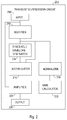
- FIG. 2 is a block diagram illustrating an embodiment of a transient suppression circuit 208, which represents an embodiment of transient suppression circuit 108.
- transient suppression circuit 208 includes an input 210, a rectifier 212, a threshold envelope generator 214, an accumulator 218, a normalizer 220, a gain calculator 222, an amplifier 224, and an output 226.
- Input 210 receives the input signal, such as from microphone 102.
- processing circuit 104 may precondition the input signal before it is received by input 210.
- the preconditioning may include, but is not limited to, amplification, filtering, digitization, and/or decimation.
- Rectifier 212 rectifies the input signal.
- Threshold envelope generator 214 generates a threshold signal being an envelope of the rectified input signal.
- Accumulator 218 produces an accumulator value by accumulating a difference between an amplitude of the rectified input signal and an amplitude of the threshold signal.
- Normalizer 220 normalizes the accumulator value to keep performance of the transient suppression consistent across various levels of the input signal.
- Gain calculator 222 determines an applied gain using the normalized accumulator value.
- Amplifier 224 produces the output signal by applying the applied gain to the input signal.
- Output 226 relays the output signal, such as to speaker 106.
- processing circuit 104 may further process the input and/or the output signal before the output signal is received by speaker 106. Such further processing may include, but is not limited to, application of various sound processing techniques such as feedback cancellation, directionality control, spatial perception enhancement, speech intelligibility enhancement, and/or reduction of noises other than the transient sounds.
- FIG. 3 is a block diagram illustrating an embodiment of a transient suppression circuit 308, which represents an embodiment of transient suppression circuit 208.
- transient suppression circuit 308 includes an input 310, a decimator 311, a rectifier 312, a threshold envelope generator 314, a threshold scaling multiplier 315, an accumulator 318, a normalizer 320, a gain calculator 322, an output multiplier 324, and an output 326.
- Various other embodiments of transient suppression circuit 208 may include more or less circuit elements.
- decimator 311 may be used, and its decimation factor may be determined, based on the overall computational cost of processing circuit 104.
- processing circuit 308 includes a digital circuit that processes signals in digital domain.
- Input 310 receives the input signal, which is digitized.
- decimator 311 decimates the input signal.
- decimator 311 decimates the input signal by summing 8 samples and shifting right 3 places.
- decimator 311 decimates the input signal by a decimation factor of 8.
- Rectifier 312 represents an embodiment of rectifier 212 and rectifies the decimated input signal.
- Threshold envelope generator 314 represents an embodiment of threshold envelope generator 214 and generates a threshold signal.
- the threshold signal is a time domain broadband signal that is an envelope of the rectified input signal.
- Threshold scaling multiplier 315 scales the threshold signal by multiplying the threshold signal by a threshold shift.
- Accumulator 318 represents an embodiment of accumulator 218 and produces an accumulator value by accumulating the difference between the amplitude of the rectified input signal and the amplitude of the threshold signal.
- the accumulator value i.e., the accumulated difference between the amplitude of the rectified input signal and the amplitude of the threshold signal
- Normalizer 320 represents an embodiment of normalizer 220 and normalizes the accumulator value to keep performance of the transient suppression consistent across various levels of the input signal.
- Gain calculator 322 represents gain calculator 222 and produces an applied gain using the normalized accumulator value.
- the applied gain is to be applied to the input signal to produce the output signal.
- Gain calculator 322 includes a target gain calculator 332 and an applied gain calculator 333.
- Target gain calculator 332 calculates a target gain using the normalized accumulator value.
- Applied gain calculator 333 dynamically determines the applied gain based on the target gain.
- applied gain calculator 333 sets the applied gain to the target gain when the applied gain is greater than the target gain, and determines the applied gain using the target gain and a rise rate parameter when the applied gain is not greater than the target gain. In various embodiments, when the applied gain is not greater than the target gain, applied gain calculator 333 determines the applied gain as a sum of the applied gain and the applied gain multiplied by the rise rate parameter. The rise rate parameter controls a recovery time of the applied gain. This keeps the applied gain at a low level for a brief period of time after the threshold level has increased enough to drop the accumulator value, which increases the target gain. In various embodiments, applied gain calculator 333 sets the applied gain to 1 when the determined applied gain exceeds 1.
- Output multiplier 324 represents an embodiment of amplifier 224 and produces the output signal by multiplying the input signal by the applied gain. Output 324 relays the output signal to speaker 106 or other portions of processing circuit 104 for additional processing.
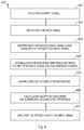
- FIG. 4 is a flow chart illustrating an embodiment of a method 440 for transient sound suppression.
- transient suppression circuit 208 or 308 can be configured to perform method 440.
- an input signal is received.
- the input signal is received from a microphone of a hearing assistance device such as a hearing aid and represents input sounds received from the environment of the listener such as a hearing aid wearer.
- the input signal is to be processed to produce output sounds for delivery to the listener using the hearing assistance device.
- the input sounds may include target sounds and transient sounds.
- method 400 is performed to attenuate the transient sounds using a time-domain process.
- the input signal may be decimated in various ways.
- the input signal is decimated using a decimation factor of 8.
- the input signal is decimated by summing 8 samples and shifting right 3 places.
- the input signal is rectified. If the input signal is decimated, the rectified signal is the rectified decimated signal.
- a threshold signal is generated.
- the threshold signal is an envelope of the rectified input signal generated.
- the envelope is a time domain broadband signal.
- the envelope is scaled to be used as the threshold signal.
- a difference between an amplitude of the rectified input signal and an amplitude of the threshold signal is accumulated by using an accumulator.
- the accumulated difference is also referred to as the accumulator value.
- the accumulated difference (accumulator value) is normalized using the input signal. This allows method 440 to be performed consistently across variations in the level of the input signal.
- the accumulated difference is normalized by multiplying the accumulated difference with a normalization signal produced using the input signal or the rectified input signal.
- an applied gain is determined using the normalized accumulated difference.
- the applied gain is determined by dynamically calculating a target gain using the normalized accumulated difference and dynamically determining the applied gain based on the target gain.
- the applied gain is dynamically determined by setting the applied gain to the target gain when the applied gain is greater than the target gain and setting the applied gain to a sum of the applied gain and the applied gain multiplied by a rise rate parameter when the applied gain is not greater than the target gain.
- the rise rate parameter controls a recovery time of the applied gain. In one embodiment, if the dynamically determined applied gain exceeds 1, it is set to 1.
- the applied gain is applied to the input signal to produce the output signal.
- additional sound processing techniques may be applied to further process the output signal before it is delivered to be heard by the listener.
- Hearing assistance devices typically include at least one enclosure or housing, a microphone, hearing assistance device electronics including processing electronics, and a speaker or "receiver.”
- Hearing assistance devices may include a power source, such as a battery.
- the battery may be rechargeable.
- multiple energy sources may be employed.
- the microphone is optional.
- the receiver is optional.
- Antenna configurations may vary and may be included within an enclosure for the electronics or be external to an enclosure for the electronics.
- digital hearing aids include a processor.
- processing circuit 104 including transient suppression circuit 108 and its various embodiments as discussed in this document, may be implemented in such a processor.
- programmable gains may be employed to adjust the hearing aid output to a wearer's particular hearing impairment.
- the processor may be a digital signal processor (DSP), microprocessor, microcontroller, other digital logic, or combinations thereof.
- DSP digital signal processor
- the processing may be done by a single processor, or may be distributed over different processors.
- the processing of signals referenced in this application can be performed using the processor or over different devices. Processing may be done in the digital domain, the analog domain, or combinations thereof. Processing may be done using subband processing techniques.
- Processing may be done using frequency domain or time domain approaches. Some processing may involve both frequency and time domain aspects. For brevity, in some examples drawings may omit certain blocks that perform frequency synthesis, frequency analysis, analog-to-digital conversion, digital-to-analog conversion, amplification, buffering, and certain types of filtering and processing.
- the processor is adapted to perform instructions stored in one or more memories, which may or may not be explicitly shown. Various types of memory may be used, including volatile and nonvolatile forms of memory.
- the processor or other processing devices execute instructions to perform a number of signal processing tasks.
- Such embodiments may include analog components in communication with the processor to perform signal processing tasks, such as sound reception by a microphone, or playing of sound using a receiver (i.e., in applications where such transducers are used).
- signal processing tasks such as sound reception by a microphone, or playing of sound using a receiver (i.e., in applications where such transducers are used).
- different realizations of the block diagrams, circuits, and processes set forth herein can be created by one of skill in the art without departing from the scope of the present subject matter.
- hearing assistance devices may embody the present subject matter without departing from the scope of the present disclosure.
- the devices depicted in the figures are intended to demonstrate the subject matter, but not necessarily in a limited, exhaustive, or exclusive sense. It is also understood that the present subject matter can be used with a device designed for use in the right ear or the left ear or both ears of the wearer.
- the present subject matter may be employed in hearing assistance devices, such as headsets, headphones, and similar hearing devices.
- hearing assistance devices including hearing aids, including but not limited to, behind-the-ear (BTE), in-the-ear (ITE), in-the-canal (ITC), receiver-in-canal (RIC), or completely-in-the-canal (CIC) type hearing aids.
- BTE behind-the-ear
- ITE in-the-ear
- ITC in-the-canal
- RIC receiver-in-canal
- CIC completely-in-the-canal
- hearing assistance devices including but not limited to, behind-the-ear (BTE), in-the-ear (ITE), in-the-canal (ITC), receiver-in-canal (RIC), or completely-in-the-canal (CIC) type hearing aids.
- BTE behind-the-ear
- ITE in-the-ear
- ITC in-the-canal
- RIC receiver-in-canal
- CIC completely-in-the-canal
- hearing assistance devices including but not limited to, behind-the-ear (BTE), in
- the present subject matter can also be used in hearing assistance devices generally, such as cochlear implant type hearing devices and such as deep insertion devices having a transducer, such as a receiver or microphone, whether custom fitted, standard fitted, open fitted and/or occlusive fitted. It is understood that other hearing assistance devices not expressly stated herein may be used in conjunction with the present subject matter.
Abstract
Description
- This document relates generally to hearing assistance devices and more particularly to a computationally efficient method and apparatus for transient sound suppression.
- One or more hearing instruments may be worn on one or both sides of a person's head to deliver sounds to the person's ear(s). An example of such hearing instruments includes one or more hearing aids that are used to assist a patient suffering hearing loss by transmitting amplified sounds to one or both ear canals of the patient. While the patient (hearing aid wearer) benefits from amplified sounds such as speech and music, other sounds when being amplified may be unpleasant. For example, for many hearing aid wearers, especially those who are new to wearing hearing aids, transient sounds can be very unpleasant. Examples of the transient sounds include sounds of placing dishes or silverware on a hard surface and the closing of cupboards or doors. While such transient sounds may not be loud enough to trigger output compression limiting, they may still be perceived by hearing aid wearers as annoying. Thus, there is a need to reduce the harshness of the transient sounds while not affecting the sounds that are intended to be heard by the hearing aid wearers.
- An audio system includes a transient suppression circuit that rectifies an input signal representing target sounds and transient sounds and produces a threshold envelope of the rectified input signal. The transient suppression circuit accumulates the difference between the rectified input signal and the threshold envelope, and normalizes the accumulated difference using the rectified input signal. A gain is calculated using this normalized accumulated difference and applied to the input signal to suppress the transient sounds without substantially affecting the target sounds.
- In one embodiment, a hearing assistance device includes a microphone to receive input sounds and produce an input signal representing the input sounds, a speaker configured to receive an output signal and produce output sounds based on the output signal, and a processing circuit to produce the output signal by processing the input signal. The processing circuit includes a rectifier, a threshold envelope generator, an accumulator, a normalizer, a gain calculator, and an amplifier. The rectifier rectifies the input signal. The threshold envelope generator generates a threshold signal being an envelope of the rectified input signal. The accumulator produces an accumulator value by accumulating a difference between an amplitude of the rectified input signal and an amplitude of the threshold signal. The normalizer normalizes the accumulator value using the rectified input signal. The gain calculator determines an applied gain using the normalized accumulator value. The amplifier produces the output signal by applying the applied gain to the input signal.
- A method for operating a hearing assistance device is provided. In one embodiment, the method includes receiving an input signal representing input sounds, transmitting output sounds to an ear canal of a listener, and processing the input signal to produce the output sounds, including attenuating transient sounds using a time-domain process. The time-domain process includes rectifying the input signal, generating a threshold signal being an envelope of the rectified input signal, accumulating a difference between an amplitude of the rectified input signal and an amplitude of the threshold signal, normalizing the accumulated difference using the rectified input signal, determining an applied gain using the normalized accumulated difference, and applying the applied gain to the input signal.
- This Summary is an overview of some of the teachings of the present application and not intended to be an exclusive or exhaustive treatment of the present subject matter. Further details about the present subject matter are found in the detailed description and appended claims. The scope of the present invention is defined by the appended claims and their legal equivalents.
-
-
FIG. 1 is a block diagram illustrating an embodiment of an audio system with transient sound suppression. -
FIG. 2 is a block diagram illustrating an embodiment of a transient suppression circuit. -
FIG. 3 is a block diagram illustrating another embodiment of the transient suppression circuit. -
FIG. 4 is a flow chart illustrating an embodiment of a method for transient sound suppression. - The following detailed description of the present subject matter refers to subject matter in the accompanying drawings which show, by way of illustration, specific aspects and embodiments in which the present subject matter may be practiced. These embodiments are described in sufficient detail to enable those skilled in the art to practice the present subject matter. References to "an", "one", or "various" embodiments in this disclosure are not necessarily to the same embodiment, and such references contemplate more than one embodiment. The following detailed description is demonstrative and not to be taken in a limiting sense. The scope of the present subject matter is defined by the appended claims, along with the full scope of legal equivalents to which such claims are entitled.
- The present document discusses an audio system, such as a hearing assistance system, that suppresses transient sounds in processing an acoustic signal that is to be delivered to a listener such as a hearing aid wearer. In this document, "transient suppression" includes reduction or attenuation of transient sounds. A "transient sound", as referred to as a "transient" is a sound of high amplitude and short duration at the beginning of a waveform that may occur in phenomena such as music, speech, or noises. A transient may include any sudden change in the amplitude of an acoustic signal, such as a sudden "wideband event" in an acoustic signal that is otherwise a substantially steady-state signal. The listener of the hearing assistance system, such as the hearing aid wearer, may find transient sounds particularly loud and annoying, especially when the transient sounds include noises such as sounds from slamming doors, dropping a hard object on a hard surface, and other sounds that the listener would not care to hear. Various systems perform transient suppression by quickly reducing the gain in the sound processing when a transient sound occurs, and then quickly revert to the original gain. The goal is to suppress the transient sounds (that causes discomfort when heard by the listener) while not affecting the delivery of speech, music and other environmental sounds that are intended to be heard by the listener. In some known examples, transient suppression is performed by using frequency domain analysis or spectral flux methods.
- The present subject matter achieves transient suppression using a broadband time domain processing that is computationally efficient. In various embodiments, the present audio system reduces objectionable audio transients, while not substantially affecting other sounds, at a low computational cost. The low computational cost, among other things, makes the present subject matter suitable for use in a hearing aid where computational resources are limited.
- In various embodiments, the present audio system detects transient sounds in an input signal by accumulating difference between the rectified input signal and a smoothed envelope of the input signal. Waveforms such as those typically seen in speech and music signals are substantially unaffected, while waveforms of percussive transient sounds trigger suppression of the transient sounds. In various embodiments, by suppressing the transient sounds, the present audio system provides listening comfort. When not being bothered by loud transient sounds, the listener may choose to increase the volume of the sound (processed input signal) delivered to him or her, which may improve speech intelligibility.
- In various embodiments, the present audio system can be configured to generate a detection signal being the accumulation of the amount by which the input signal exceeds a dynamically changing threshold, normalize the detection signal using the input signal, and generate a target gain for the processing of the input signal (sound) from the normalized detection signal.
-
FIG. 1 is a block diagram illustrating an embodiment of anaudio system 100 with transient sound suppression. One example ofaudio system 100 includes a hearing assistance system. The hearing assistance system may include one or more hearing aids configured to be worn by a listener (hearing aid wearer) who may suffer hearing loss by delivering amplified sound to the listener to compensate for the hearing loss.System 100 includes amicrophone 102, aspeaker 106, and aprocessing circuit 104 coupled betweenmicrophone 102 andspeaker 106. Microphone 102 receives input sounds from the listener's environment and produces an input signal representing the input sounds. The input sounds may include target sounds and transient sounds. The target sounds are sounds intended to be heard by the listener, such as speech, music, and audio notifications such as those generated from home electric appliances. Transient sounds include short-duration sounds that may be loud and annoying to the listener.Processing circuit 104 produces an output signal by processing the input signal representing the input sounds. Speaker 106 (also known as a receiver in a hearing assistance system) produces output sounds using the output signal and transmits the output sounds to the listener.Processing circuit 104 includes atransient suppression circuit 108 that suppresses the transient sounds in the input sounds. In various embodiments,transient suppression circuit 108 substantially attenuates the transient sounds without substantially affecting the target sounds in the input sounds. - In various embodiments,
transient suppression circuit 108 rectifies the input signal and produces a threshold envelope that is used as a comparison threshold for calculating a magnitude of the transient sounds, and a normalization signal that is used to normalize the calculation based on the general loudness of the input signal (which conveys the loudness of the environment). The threshold envelope has fast time constants to follow the general envelope of the rectified input signal, and may be scaled by threshold shift.Transient suppression circuit 108 then adds the difference between the rectified input signal and the scaled threshold envelope to an accumulator. This accumulated difference increases at the onset of sudden increases in the level of the rectified input signal, and is scaled by the normalization signal, which has an amplitude that varies with the level of the rectified input signal. The normalized difference between the rectified input signal and the scaled threshold envelope is then used to determine a gain that is applied to the input signal to produce the output signal. -
FIG. 2 is a block diagram illustrating an embodiment of atransient suppression circuit 208, which represents an embodiment oftransient suppression circuit 108. In the illustrated embodiment,transient suppression circuit 208 includes aninput 210, arectifier 212, athreshold envelope generator 214, anaccumulator 218, anormalizer 220, again calculator 222, anamplifier 224, and anoutput 226. -
Input 210 receives the input signal, such as frommicrophone 102. In various embodiments,processing circuit 104 may precondition the input signal before it is received byinput 210. The preconditioning may include, but is not limited to, amplification, filtering, digitization, and/or decimation.Rectifier 212 rectifies the input signal.Threshold envelope generator 214 generates a threshold signal being an envelope of the rectified input signal.Accumulator 218 produces an accumulator value by accumulating a difference between an amplitude of the rectified input signal and an amplitude of the threshold signal.Normalizer 220 normalizes the accumulator value to keep performance of the transient suppression consistent across various levels of the input signal.Gain calculator 222 determines an applied gain using the normalized accumulator value.Amplifier 224 produces the output signal by applying the applied gain to the input signal.Output 226 relays the output signal, such as tospeaker 106. In various embodiments,processing circuit 104 may further process the input and/or the output signal before the output signal is received byspeaker 106. Such further processing may include, but is not limited to, application of various sound processing techniques such as feedback cancellation, directionality control, spatial perception enhancement, speech intelligibility enhancement, and/or reduction of noises other than the transient sounds. -
FIG. 3 is a block diagram illustrating an embodiment of atransient suppression circuit 308, which represents an embodiment oftransient suppression circuit 208. In the illustrated embodiment,transient suppression circuit 308 includes aninput 310, adecimator 311, arectifier 312, athreshold envelope generator 314, athreshold scaling multiplier 315, anaccumulator 318, anormalizer 320, again calculator 322, anoutput multiplier 324, and anoutput 326. Various other embodiments oftransient suppression circuit 208 may include more or less circuit elements. For example,decimator 311 may be used, and its decimation factor may be determined, based on the overall computational cost ofprocessing circuit 104. - In various embodiments,
processing circuit 308 includes a digital circuit that processes signals in digital domain.Input 310 receives the input signal, which is digitized. In one embodiment, as illustrated inFIG. 3 ,decimator 311 decimates the input signal. In one embodiment,decimator 311 decimates the input signal by summing 8 samples and shifting right 3 places. In anotherembodiment decimator 311 decimates the input signal by a decimation factor of 8.Rectifier 312 represents an embodiment ofrectifier 212 and rectifies the decimated input signal. -
Threshold envelope generator 314 represents an embodiment ofthreshold envelope generator 214 and generates a threshold signal. The threshold signal is a time domain broadband signal that is an envelope of the rectified input signal.Threshold scaling multiplier 315 scales the threshold signal by multiplying the threshold signal by a threshold shift. -
Accumulator 318 represents an embodiment ofaccumulator 218 and produces an accumulator value by accumulating the difference between the amplitude of the rectified input signal and the amplitude of the threshold signal. The accumulator value (i.e., the accumulated difference between the amplitude of the rectified input signal and the amplitude of the threshold signal) shows a large peak corresponding to the onset of a transient sound. This peak will result in a sudden decreases in a gain value applied to the input signal, and that gain value recovers quickly to unity at a specified rate, as discussed with respect to gaincalculator 322 below. -
Normalizer 320 represents an embodiment ofnormalizer 220 and normalizes the accumulator value to keep performance of the transient suppression consistent across various levels of the input signal. -
Gain calculator 322 representsgain calculator 222 and produces an applied gain using the normalized accumulator value. The applied gain is to be applied to the input signal to produce the output signal.Gain calculator 322 includes atarget gain calculator 332 and an appliedgain calculator 333.Target gain calculator 332 calculates a target gain using the normalized accumulator value. In one embodiment,target gain calculator 332 dynamically calculates the target gain by subtracting the normalized accumulator value from 1 (i.e., target gain = 1 - normalized accumulator value), and sets the target gain to a minimum target gain value when the calculated target gain is less than the minimum target gain.Applied gain calculator 333 dynamically determines the applied gain based on the target gain. In one embodiment, appliedgain calculator 333 sets the applied gain to the target gain when the applied gain is greater than the target gain, and determines the applied gain using the target gain and a rise rate parameter when the applied gain is not greater than the target gain. In various embodiments, when the applied gain is not greater than the target gain, appliedgain calculator 333 determines the applied gain as a sum of the applied gain and the applied gain multiplied by the rise rate parameter. The rise rate parameter controls a recovery time of the applied gain. This keeps the applied gain at a low level for a brief period of time after the threshold level has increased enough to drop the accumulator value, which increases the target gain. In various embodiments, appliedgain calculator 333 sets the applied gain to 1 when the determined applied gain exceeds 1. -
Output multiplier 324 represents an embodiment ofamplifier 224 and produces the output signal by multiplying the input signal by the applied gain.Output 324 relays the output signal tospeaker 106 or other portions ofprocessing circuit 104 for additional processing. -
FIG. 4 is a flow chart illustrating an embodiment of amethod 440 for transient sound suppression. In various embodiments,transient suppression circuit method 440. - At 441, an input signal is received. In various embodiments, the input signal is received from a microphone of a hearing assistance device such as a hearing aid and represents input sounds received from the environment of the listener such as a hearing aid wearer. The input signal is to be processed to produce output sounds for delivery to the listener using the hearing assistance device. The input sounds may include target sounds and transient sounds. In various embodiments, method 400 is performed to attenuate the transient sounds using a time-domain process.
- In various embodiments, the input signal may be decimated in various ways. In one embodiment, the input signal is decimated using a decimation factor of 8. In one embodiment, the input signal is decimated by summing 8 samples and shifting right 3 places.
- At 442, the input signal is rectified. If the input signal is decimated, the rectified signal is the rectified decimated signal.
- At 443, a threshold signal is generated. The threshold signal is an envelope of the rectified input signal generated. The envelope is a time domain broadband signal. In one embodiment, the envelope is scaled to be used as the threshold signal.
- At 444, a difference between an amplitude of the rectified input signal and an amplitude of the threshold signal is accumulated by using an accumulator. The accumulated difference is also referred to as the accumulator value.
- At 445, the accumulated difference (accumulator value) is normalized using the input signal. This allows
method 440 to be performed consistently across variations in the level of the input signal. In various embodiments, the accumulated difference is normalized by multiplying the accumulated difference with a normalization signal produced using the input signal or the rectified input signal. - At 446, an applied gain is determined using the normalized accumulated difference. In one embodiment, the applied gain is determined by dynamically calculating a target gain using the normalized accumulated difference and dynamically determining the applied gain based on the target gain. In one embodiment, the target gain is dynamically calculated by calculating the target gain by subtracting the normalized accumulated difference from 1 (i.e., target gain = 1 - normalized accumulator value) and setting the target gain to a minimum target gain value when the calculated target gain is less than the minimum target gain. In one embodiment, the applied gain is dynamically determined by setting the applied gain to the target gain when the applied gain is greater than the target gain and setting the applied gain to a sum of the applied gain and the applied gain multiplied by a rise rate parameter when the applied gain is not greater than the target gain. The rise rate parameter controls a recovery time of the applied gain. In one embodiment, if the dynamically determined applied gain exceeds 1, it is set to 1.
- At 447, the applied gain is applied to the input signal to produce the output signal. In various embodiments, additional sound processing techniques may be applied to further process the output signal before it is delivered to be heard by the listener.
- Hearing assistance devices typically include at least one enclosure or housing, a microphone, hearing assistance device electronics including processing electronics, and a speaker or "receiver." Hearing assistance devices may include a power source, such as a battery. In various embodiments, the battery may be rechargeable. In various embodiments multiple energy sources may be employed. It is understood that in various embodiments the microphone is optional. It is understood that in various embodiments the receiver is optional. It is understood that variations in communications protocols, antenna configurations, and combinations of components may be employed without departing from the scope of the present subject matter. Antenna configurations may vary and may be included within an enclosure for the electronics or be external to an enclosure for the electronics. Thus, the examples set forth herein are intended to be demonstrative and not a limiting or exhaustive depiction of variations.
- It is understood that digital hearing aids include a processor. In various embodiments of the present subject matter, processing
circuit 104, includingtransient suppression circuit 108 and its various embodiments as discussed in this document, may be implemented in such a processor. In digital hearing aids with a processor, programmable gains may be employed to adjust the hearing aid output to a wearer's particular hearing impairment. The processor may be a digital signal processor (DSP), microprocessor, microcontroller, other digital logic, or combinations thereof. The processing may be done by a single processor, or may be distributed over different processors. The processing of signals referenced in this application can be performed using the processor or over different devices. Processing may be done in the digital domain, the analog domain, or combinations thereof. Processing may be done using subband processing techniques. Processing may be done using frequency domain or time domain approaches. Some processing may involve both frequency and time domain aspects. For brevity, in some examples drawings may omit certain blocks that perform frequency synthesis, frequency analysis, analog-to-digital conversion, digital-to-analog conversion, amplification, buffering, and certain types of filtering and processing. In various embodiments the processor is adapted to perform instructions stored in one or more memories, which may or may not be explicitly shown. Various types of memory may be used, including volatile and nonvolatile forms of memory. In various embodiments, the processor or other processing devices execute instructions to perform a number of signal processing tasks. Such embodiments may include analog components in communication with the processor to perform signal processing tasks, such as sound reception by a microphone, or playing of sound using a receiver (i.e., in applications where such transducers are used). In various embodiments, different realizations of the block diagrams, circuits, and processes set forth herein can be created by one of skill in the art without departing from the scope of the present subject matter. - It is further understood that different hearing assistance devices may embody the present subject matter without departing from the scope of the present disclosure. The devices depicted in the figures are intended to demonstrate the subject matter, but not necessarily in a limited, exhaustive, or exclusive sense. It is also understood that the present subject matter can be used with a device designed for use in the right ear or the left ear or both ears of the wearer.
- The present subject matter may be employed in hearing assistance devices, such as headsets, headphones, and similar hearing devices.
- The present subject matter is demonstrated for hearing assistance devices, including hearing aids, including but not limited to, behind-the-ear (BTE), in-the-ear (ITE), in-the-canal (ITC), receiver-in-canal (RIC), or completely-in-the-canal (CIC) type hearing aids. It is understood that behind-the-ear type hearing aids may include devices that reside substantially behind the ear or over the ear. Such devices may include hearing aids with receivers associated with the electronics portion of the behind-the-ear device, or hearing aids of the type having receivers in the ear canal of the user, including but not limited to receiver-in-canal (RIC) or receiver-in-the-ear (RITE) designs. The present subject matter can also be used in hearing assistance devices generally, such as cochlear implant type hearing devices and such as deep insertion devices having a transducer, such as a receiver or microphone, whether custom fitted, standard fitted, open fitted and/or occlusive fitted. It is understood that other hearing assistance devices not expressly stated herein may be used in conjunction with the present subject matter.
- This application is intended to cover adaptations or variations of the present subject matter. It is to be understood that the above description is intended to be illustrative, and not restrictive. The scope of the present subject matter should be determined with reference to the appended claims, along with the full scope of legal equivalents to which such claims are entitled.
Claims (15)
- A hearing assistance device for use by a listener having an ear canal, comprising:a microphone configured to receive input sounds and produce an input signal representing the input sounds;a speaker configured to receive an output signal and produce output sounds based on the output signal; anda processing circuit coupled between the microphone and the speaker, the processing circuit configured to process the input signal to produce the output signal and including:a rectifier configured to rectify the input signal;a threshold envelope generator configured to generate a threshold signal being an envelope of the rectified input signal;an accumulator configured to produce an accumulator value by accumulating a difference between an amplitude of the rectified input signal and an amplitude of the threshold signal;a normalizer configured to normalize the accumulator value using the rectified input signal;a gain calculator configured to determine an applied gain using the normalized accumulator value; andan amplifier configured to produce the output signal by applying the applied gain to the input signal.
- The hearing assistance device according to claim 1, comprising a hearing aid configured to be worn by the listener to deliver the output sounds to the ear canal of the listener, the hearing aid including the microphone, the speaker, and the processing circuit.
- The hearing assistance device according to any of the preceding claims, wherein the processing circuit further comprises a decimator coupled to the rectifier and configured to decimate the input signal, and the rectifier is configured to rectify the decimated input signal.
- The hearing assistance device according to any of the preceding claims, wherein the processing circuit further comprises a threshold scaling multiplier configured to scale the threshold signal by multiplying the threshold signal by a threshold shift, and the accumulator is configured to produce the accumulator value by accumulating the difference between the amplitude of the rectified input signal and the amplitude of the scaled threshold signal.
- The hearing assistance device of according to any of the preceding claims, wherein the gain calculator comprises:a target gain calculator configured to calculate a target gain using the normalized accumulator value; andan applied gain calculator configured to dynamically determine the applied gain based on the target gain.
- The hearing assistance device according to claim 5, wherein the target gain calculator is configured to dynamically calculate the target gain by subtracting the normalized accumulator value from 1 and to set the target gain to a minimum target gain value when the calculated target gain is less than the minimum target gain.
- The hearing assistance device according to any of claims 5 and 6, wherein the applied gain calculator is configured to set the applied gain to the target gain when the applied gain is greater than the target gain, to set the applied gain to a sum of the applied gain and the applied gain multiplied by a rise rate parameter when the applied gain is not greater than the target gain, the rise rate parameter controlling a recovery time of the applied gain, and to set the applied gain to 1 when the determined applied gain exceeds 1.
- A method for operating a hearing assistance device, comprising:receiving an input signal representing input sounds;transmitting output sounds to an ear canal of a listener;processing the input signal to produce the output sounds, including attenuating transient sounds using a time-domain process including:rectifying the input signal;generating a threshold signal being an envelope of the rectified input signal;accumulating a difference between an amplitude of the rectified input signal and an amplitude of the threshold signal;normalizing the accumulated difference using the rectified input signal;determining an applied gain using the normalized accumulated difference; andapplying the applied gain to the input signal.
- The method according to claim 8, comprising receiving the input signal using a microphone of a hearing aid, transmitting the output sounds to the ear canal of the listener using a receiver of the hearing aid, and processing the input signal to produce the output sounds using a processor of the hearing aid.
- The method according to any of claims 8 and 9, wherein determining the applied gain comprises:dynamically calculating a target gain using the normalized accumulated difference; anddynamically determining the applied gain based on the target gain.
- The method according to claim 10, wherein dynamically calculating the target gain comprises dynamically calculating the target gain by subtracting the normalized accumulated difference from 1.
- The method according to claim 11, wherein dynamically calculating the target gain further comprises setting the target gain to a minimum target gain value when the calculated target gain is less than the minimum target gain.
- The method according to claim 12, wherein dynamically determining the applied gain comprises setting the applied gain to the target gain when the applied gain is greater than the target gain.
- The method according to claim 13, wherein dynamically determining the applied gain further comprises setting the applied gain to a sum of the applied gain and the applied gain multiplied by a rise rate parameter when the applied gain is not greater than the target gain, the rise rate parameter controlling a recovery time of the applied gain.
- The method according to claim 12, wherein dynamically determining the applied gain further comprises setting the applied gain to 1 when the determined applied gain exceeds 1.
Applications Claiming Priority (1)
| Application Number | Priority Date | Filing Date | Title |
|---|---|---|---|
| US14/722,392 US9699572B2 (en) | 2015-05-27 | 2015-05-27 | Method and apparatus for suppressing transient sounds in hearing assistance devices |
Publications (2)
| Publication Number | Publication Date |
|---|---|
| EP3099085A1 true EP3099085A1 (en) | 2016-11-30 |
| EP3099085B1 EP3099085B1 (en) | 2018-01-03 |
Family
ID=56081385
Family Applications (1)
| Application Number | Title | Priority Date | Filing Date |
|---|---|---|---|
| EP16171659.2A Active EP3099085B1 (en) | 2015-05-27 | 2016-05-27 | Method and apparatus for suppressing transient sounds in hearing assistance devices |
Country Status (3)
| Country | Link |
|---|---|
| US (1) | US9699572B2 (en) |
| EP (1) | EP3099085B1 (en) |
| DK (1) | DK3099085T3 (en) |
Cited By (1)
| Publication number | Priority date | Publication date | Assignee | Title |
|---|---|---|---|---|
| WO2021143249A1 (en) * | 2020-09-01 | 2021-07-22 | 平安科技(深圳)有限公司 | Transient noise suppression-based audio processing method, apparatus, device, and medium |
Families Citing this family (1)
| Publication number | Priority date | Publication date | Assignee | Title |
|---|---|---|---|---|
| CN111564161B (en) * | 2020-04-28 | 2023-07-07 | 世邦通信股份有限公司 | Sound processing device and method for intelligently suppressing noise, terminal equipment and readable medium |
Citations (4)
| Publication number | Priority date | Publication date | Assignee | Title |
|---|---|---|---|---|
| US4052568A (en) * | 1976-04-23 | 1977-10-04 | Communications Satellite Corporation | Digital voice switch |
| WO1996013096A1 (en) * | 1994-10-24 | 1996-05-02 | Cochlear Limited | Automatic sensitivity control |
| WO2007031499A1 (en) * | 2005-09-12 | 2007-03-22 | Siemens Audiologische Technik Gmbh | Method for attenuating interfering noise and corresponding hearing device |
| WO2010083879A1 (en) * | 2009-01-20 | 2010-07-29 | Widex A/S | Hearing aid and a method of detecting and attenuating transients |
Family Cites Families (5)
| Publication number | Priority date | Publication date | Assignee | Title |
|---|---|---|---|---|
| US5396560A (en) | 1993-03-31 | 1995-03-07 | Trw Inc. | Hearing aid incorporating a novelty filter |
| US7076073B2 (en) * | 2001-04-18 | 2006-07-11 | Gennum Corporation | Digital quasi-RMS detector |
| DK2002691T3 (en) | 2006-04-01 | 2012-01-23 | Widex As | Hearing aid and method for controlling signal processing in a hearing aid |
| PL2887997T3 (en) * | 2012-08-27 | 2018-04-30 | Med-El Elektromedizinische Geräte GmbH | Reduction of transient sounds in hearing implants |
| US9693153B2 (en) | 2015-05-27 | 2017-06-27 | Starkey Laboratories, Inc. | Method and apparatus for suppressing transient sounds in hearing assistance devices |
-
2015
- 2015-05-27 US US14/722,392 patent/US9699572B2/en active Active
-
2016
- 2016-05-27 DK DK16171659.2T patent/DK3099085T3/en active
- 2016-05-27 EP EP16171659.2A patent/EP3099085B1/en active Active
Patent Citations (4)
| Publication number | Priority date | Publication date | Assignee | Title |
|---|---|---|---|---|
| US4052568A (en) * | 1976-04-23 | 1977-10-04 | Communications Satellite Corporation | Digital voice switch |
| WO1996013096A1 (en) * | 1994-10-24 | 1996-05-02 | Cochlear Limited | Automatic sensitivity control |
| WO2007031499A1 (en) * | 2005-09-12 | 2007-03-22 | Siemens Audiologische Technik Gmbh | Method for attenuating interfering noise and corresponding hearing device |
| WO2010083879A1 (en) * | 2009-01-20 | 2010-07-29 | Widex A/S | Hearing aid and a method of detecting and attenuating transients |
Cited By (1)
| Publication number | Priority date | Publication date | Assignee | Title |
|---|---|---|---|---|
| WO2021143249A1 (en) * | 2020-09-01 | 2021-07-22 | 平安科技(深圳)有限公司 | Transient noise suppression-based audio processing method, apparatus, device, and medium |
Also Published As
| Publication number | Publication date |
|---|---|
| DK3099085T3 (en) | 2018-04-16 |
| EP3099085B1 (en) | 2018-01-03 |
| US9699572B2 (en) | 2017-07-04 |
| US20160353213A1 (en) | 2016-12-01 |
Similar Documents
| Publication | Publication Date | Title |
|---|---|---|
| JP4359599B2 (en) | hearing aid | |
| WO1990005436A1 (en) | Feedback suppression in digital signal processing hearing aids | |
| US20050141733A1 (en) | Adaptive dynamic range optimisation sound processor | |
| EP2339870B1 (en) | Acoustic feedback event monitoring system for hearing assistance device | |
| JP2020025250A (en) | Binaural hearing device system with binaural active occlusion cancellation function | |
| EP2901715A1 (en) | Method for operating a binaural hearing system and binaural hearing system | |
| EP2560410B1 (en) | Control of output modulation in a hearing instrument | |
| US10966032B2 (en) | Hearing apparatus with a facility for reducing a microphone noise and method for reducing microphone noise | |
| EP2942777B1 (en) | Method and apparatus for pre-processing speech to maintain speech intelligibility | |
| EP3099085B1 (en) | Method and apparatus for suppressing transient sounds in hearing assistance devices | |
| EP3223278B1 (en) | Noise characterization and attenuation using linear predictive coding | |
| CN105430586B (en) | Method and apparatus for feedback inhibition | |
| US20130188811A1 (en) | Method of controlling sounds generated in a hearing aid and a hearing aid | |
| US9693153B2 (en) | Method and apparatus for suppressing transient sounds in hearing assistance devices | |
| EP3065422B1 (en) | Techniques for increasing processing capability in hear aids | |
| US20150092966A1 (en) | Method of sound processing in a hearing aid and a hearing aid | |
| EP4035420A1 (en) | A method of operating an ear level audio system and an ear level audio system | |
| EP3420740B1 (en) | A method of operating a hearing aid system and a hearing aid system | |
| EP3395082B1 (en) | Hearing aid system and a method of operating a hearing aid system | |
| EP3099084B1 (en) | Hearing assistance device with dynamic computational resource allocation |
Legal Events
| Date | Code | Title | Description |
|---|---|---|---|
| PUAI | Public reference made under article 153(3) epc to a published international application that has entered the european phase |
Free format text: ORIGINAL CODE: 0009012 |
|
| AK | Designated contracting states |
Kind code of ref document: A1 Designated state(s): AL AT BE BG CH CY CZ DE DK EE ES FI FR GB GR HR HU IE IS IT LI LT LU LV MC MK MT NL NO PL PT RO RS SE SI SK SM TR |
|
| AX | Request for extension of the european patent |
Extension state: BA ME |
|
| 17P | Request for examination filed |
Effective date: 20170511 |
|
| RBV | Designated contracting states (corrected) |
Designated state(s): AL AT BE BG CH CY CZ DE DK EE ES FI FR GB GR HR HU IE IS IT LI LT LU LV MC MK MT NL NO PL PT RO RS SE SI SK SM TR |
|
| GRAP | Despatch of communication of intention to grant a patent |
Free format text: ORIGINAL CODE: EPIDOSNIGR1 |
|
| RIC1 | Information provided on ipc code assigned before grant |
Ipc: H04R 25/00 20060101AFI20170606BHEP |
|
| INTG | Intention to grant announced |
Effective date: 20170707 |
|
| GRAS | Grant fee paid |
Free format text: ORIGINAL CODE: EPIDOSNIGR3 |
|
| GRAA | (expected) grant |
Free format text: ORIGINAL CODE: 0009210 |
|
| RAP1 | Party data changed (applicant data changed or rights of an application transferred) |
Owner name: STARKEY LABORATORIES, INC. |
|
| RIN1 | Information on inventor provided before grant (corrected) |
Inventor name: STARKEY LABORATORIES, INC. |
|
| AK | Designated contracting states |
Kind code of ref document: B1 Designated state(s): AL AT BE BG CH CY CZ DE DK EE ES FI FR GB GR HR HU IE IS IT LI LT LU LV MC MK MT NL NO PL PT RO RS SE SI SK SM TR |
|
| REG | Reference to a national code |
Ref country code: GB Ref legal event code: FG4D |
|
| RIN1 | Information on inventor provided before grant (corrected) |
Inventor name: KINDRED, JOHN |
|
| REG | Reference to a national code |
Ref country code: CH Ref legal event code: EP Ref country code: AT Ref legal event code: REF Ref document number: 961281 Country of ref document: AT Kind code of ref document: T Effective date: 20180115 |
|
| REG | Reference to a national code |
Ref country code: IE Ref legal event code: FG4D |
|
| REG | Reference to a national code |
Ref country code: CH Ref legal event code: NV Representative=s name: SERVOPATENT GMBH, CH |
|
| REG | Reference to a national code |
Ref country code: DE Ref legal event code: R096 Ref document number: 602016001279 Country of ref document: DE |
|
| REG | Reference to a national code |
Ref country code: DK Ref legal event code: T3 Effective date: 20180413 |
|
| REG | Reference to a national code |
Ref country code: NL Ref legal event code: MP Effective date: 20180103 |
|
| REG | Reference to a national code |
Ref country code: LT Ref legal event code: MG4D |
|
| REG | Reference to a national code |
Ref country code: AT Ref legal event code: MK05 Ref document number: 961281 Country of ref document: AT Kind code of ref document: T Effective date: 20180103 |
|
| PG25 | Lapsed in a contracting state [announced via postgrant information from national office to epo] |
Ref country code: NL Free format text: LAPSE BECAUSE OF FAILURE TO SUBMIT A TRANSLATION OF THE DESCRIPTION OR TO PAY THE FEE WITHIN THE PRESCRIBED TIME-LIMIT Effective date: 20180103 |
|
| PG25 | Lapsed in a contracting state [announced via postgrant information from national office to epo] |
Ref country code: LT Free format text: LAPSE BECAUSE OF FAILURE TO SUBMIT A TRANSLATION OF THE DESCRIPTION OR TO PAY THE FEE WITHIN THE PRESCRIBED TIME-LIMIT Effective date: 20180103 Ref country code: CY Free format text: LAPSE BECAUSE OF FAILURE TO SUBMIT A TRANSLATION OF THE DESCRIPTION OR TO PAY THE FEE WITHIN THE PRESCRIBED TIME-LIMIT Effective date: 20180103 Ref country code: HR Free format text: LAPSE BECAUSE OF FAILURE TO SUBMIT A TRANSLATION OF THE DESCRIPTION OR TO PAY THE FEE WITHIN THE PRESCRIBED TIME-LIMIT Effective date: 20180103 Ref country code: NO Free format text: LAPSE BECAUSE OF FAILURE TO SUBMIT A TRANSLATION OF THE DESCRIPTION OR TO PAY THE FEE WITHIN THE PRESCRIBED TIME-LIMIT Effective date: 20180403 Ref country code: FI Free format text: LAPSE BECAUSE OF FAILURE TO SUBMIT A TRANSLATION OF THE DESCRIPTION OR TO PAY THE FEE WITHIN THE PRESCRIBED TIME-LIMIT Effective date: 20180103 Ref country code: ES Free format text: LAPSE BECAUSE OF FAILURE TO SUBMIT A TRANSLATION OF THE DESCRIPTION OR TO PAY THE FEE WITHIN THE PRESCRIBED TIME-LIMIT Effective date: 20180103 |
|
| PG25 | Lapsed in a contracting state [announced via postgrant information from national office to epo] |
Ref country code: RS Free format text: LAPSE BECAUSE OF FAILURE TO SUBMIT A TRANSLATION OF THE DESCRIPTION OR TO PAY THE FEE WITHIN THE PRESCRIBED TIME-LIMIT Effective date: 20180103 Ref country code: PL Free format text: LAPSE BECAUSE OF FAILURE TO SUBMIT A TRANSLATION OF THE DESCRIPTION OR TO PAY THE FEE WITHIN THE PRESCRIBED TIME-LIMIT Effective date: 20180103 Ref country code: AT Free format text: LAPSE BECAUSE OF FAILURE TO SUBMIT A TRANSLATION OF THE DESCRIPTION OR TO PAY THE FEE WITHIN THE PRESCRIBED TIME-LIMIT Effective date: 20180103 Ref country code: SE Free format text: LAPSE BECAUSE OF FAILURE TO SUBMIT A TRANSLATION OF THE DESCRIPTION OR TO PAY THE FEE WITHIN THE PRESCRIBED TIME-LIMIT Effective date: 20180103 Ref country code: LV Free format text: LAPSE BECAUSE OF FAILURE TO SUBMIT A TRANSLATION OF THE DESCRIPTION OR TO PAY THE FEE WITHIN THE PRESCRIBED TIME-LIMIT Effective date: 20180103 Ref country code: BG Free format text: LAPSE BECAUSE OF FAILURE TO SUBMIT A TRANSLATION OF THE DESCRIPTION OR TO PAY THE FEE WITHIN THE PRESCRIBED TIME-LIMIT Effective date: 20180403 Ref country code: IS Free format text: LAPSE BECAUSE OF FAILURE TO SUBMIT A TRANSLATION OF THE DESCRIPTION OR TO PAY THE FEE WITHIN THE PRESCRIBED TIME-LIMIT Effective date: 20180503 Ref country code: GR Free format text: LAPSE BECAUSE OF FAILURE TO SUBMIT A TRANSLATION OF THE DESCRIPTION OR TO PAY THE FEE WITHIN THE PRESCRIBED TIME-LIMIT Effective date: 20180404 |
|
| REG | Reference to a national code |
Ref country code: CH Ref legal event code: PK Free format text: BERICHTIGUNGEN |
|
| RIN2 | Information on inventor provided after grant (corrected) |
Inventor name: KINDRED, JOHN |
|
| REG | Reference to a national code |
Ref country code: DE Ref legal event code: R097 Ref document number: 602016001279 Country of ref document: DE |
|
| PG25 | Lapsed in a contracting state [announced via postgrant information from national office to epo] |
Ref country code: EE Free format text: LAPSE BECAUSE OF FAILURE TO SUBMIT A TRANSLATION OF THE DESCRIPTION OR TO PAY THE FEE WITHIN THE PRESCRIBED TIME-LIMIT Effective date: 20180103 Ref country code: RO Free format text: LAPSE BECAUSE OF FAILURE TO SUBMIT A TRANSLATION OF THE DESCRIPTION OR TO PAY THE FEE WITHIN THE PRESCRIBED TIME-LIMIT Effective date: 20180103 Ref country code: IT Free format text: LAPSE BECAUSE OF FAILURE TO SUBMIT A TRANSLATION OF THE DESCRIPTION OR TO PAY THE FEE WITHIN THE PRESCRIBED TIME-LIMIT Effective date: 20180103 Ref country code: AL Free format text: LAPSE BECAUSE OF FAILURE TO SUBMIT A TRANSLATION OF THE DESCRIPTION OR TO PAY THE FEE WITHIN THE PRESCRIBED TIME-LIMIT Effective date: 20180103 |
|
| PLBE | No opposition filed within time limit |
Free format text: ORIGINAL CODE: 0009261 |
|
| STAA | Information on the status of an ep patent application or granted ep patent |
Free format text: STATUS: NO OPPOSITION FILED WITHIN TIME LIMIT |
|
| PG25 | Lapsed in a contracting state [announced via postgrant information from national office to epo] |
Ref country code: SK Free format text: LAPSE BECAUSE OF FAILURE TO SUBMIT A TRANSLATION OF THE DESCRIPTION OR TO PAY THE FEE WITHIN THE PRESCRIBED TIME-LIMIT Effective date: 20180103 Ref country code: SM Free format text: LAPSE BECAUSE OF FAILURE TO SUBMIT A TRANSLATION OF THE DESCRIPTION OR TO PAY THE FEE WITHIN THE PRESCRIBED TIME-LIMIT Effective date: 20180103 Ref country code: CZ Free format text: LAPSE BECAUSE OF FAILURE TO SUBMIT A TRANSLATION OF THE DESCRIPTION OR TO PAY THE FEE WITHIN THE PRESCRIBED TIME-LIMIT Effective date: 20180103 |
|
| 26N | No opposition filed |
Effective date: 20181005 |
|
| REG | Reference to a national code |
Ref country code: BE Ref legal event code: MM Effective date: 20180531 |
|
| PG25 | Lapsed in a contracting state [announced via postgrant information from national office to epo] |
Ref country code: MC Free format text: LAPSE BECAUSE OF FAILURE TO SUBMIT A TRANSLATION OF THE DESCRIPTION OR TO PAY THE FEE WITHIN THE PRESCRIBED TIME-LIMIT Effective date: 20180103 |
|
| REG | Reference to a national code |
Ref country code: IE Ref legal event code: MM4A |
|
| PG25 | Lapsed in a contracting state [announced via postgrant information from national office to epo] |
Ref country code: SI Free format text: LAPSE BECAUSE OF FAILURE TO SUBMIT A TRANSLATION OF THE DESCRIPTION OR TO PAY THE FEE WITHIN THE PRESCRIBED TIME-LIMIT Effective date: 20180103 |
|
| PG25 | Lapsed in a contracting state [announced via postgrant information from national office to epo] |
Ref country code: LU Free format text: LAPSE BECAUSE OF NON-PAYMENT OF DUE FEES Effective date: 20180527 |
|
| PG25 | Lapsed in a contracting state [announced via postgrant information from national office to epo] |
Ref country code: IE Free format text: LAPSE BECAUSE OF NON-PAYMENT OF DUE FEES Effective date: 20180527 Ref country code: FR Free format text: LAPSE BECAUSE OF NON-PAYMENT OF DUE FEES Effective date: 20180531 |
|
| PG25 | Lapsed in a contracting state [announced via postgrant information from national office to epo] |
Ref country code: BE Free format text: LAPSE BECAUSE OF NON-PAYMENT OF DUE FEES Effective date: 20180531 |
|
| PG25 | Lapsed in a contracting state [announced via postgrant information from national office to epo] |
Ref country code: MT Free format text: LAPSE BECAUSE OF NON-PAYMENT OF DUE FEES Effective date: 20180527 |
|
| PG25 | Lapsed in a contracting state [announced via postgrant information from national office to epo] |
Ref country code: TR Free format text: LAPSE BECAUSE OF FAILURE TO SUBMIT A TRANSLATION OF THE DESCRIPTION OR TO PAY THE FEE WITHIN THE PRESCRIBED TIME-LIMIT Effective date: 20180103 |
|
| PG25 | Lapsed in a contracting state [announced via postgrant information from national office to epo] |
Ref country code: PT Free format text: LAPSE BECAUSE OF FAILURE TO SUBMIT A TRANSLATION OF THE DESCRIPTION OR TO PAY THE FEE WITHIN THE PRESCRIBED TIME-LIMIT Effective date: 20180103 |
|
| REG | Reference to a national code |
Ref country code: CH Ref legal event code: PCAR Free format text: NEW ADDRESS: WANNERSTRASSE 9/1, 8045 ZUERICH (CH) |
|
| PG25 | Lapsed in a contracting state [announced via postgrant information from national office to epo] |
Ref country code: HU Free format text: LAPSE BECAUSE OF FAILURE TO SUBMIT A TRANSLATION OF THE DESCRIPTION OR TO PAY THE FEE WITHIN THE PRESCRIBED TIME-LIMIT; INVALID AB INITIO Effective date: 20160527 Ref country code: MK Free format text: LAPSE BECAUSE OF NON-PAYMENT OF DUE FEES Effective date: 20180103 |
|
| GBPC | Gb: european patent ceased through non-payment of renewal fee |
Effective date: 20200527 |
|
| PG25 | Lapsed in a contracting state [announced via postgrant information from national office to epo] |
Ref country code: GB Free format text: LAPSE BECAUSE OF NON-PAYMENT OF DUE FEES Effective date: 20200527 |
|
| PGFP | Annual fee paid to national office [announced via postgrant information from national office to epo] |
Ref country code: CH Payment date: 20220517 Year of fee payment: 7 |
|
| PGFP | Annual fee paid to national office [announced via postgrant information from national office to epo] |
Ref country code: DK Payment date: 20230418 Year of fee payment: 8 Ref country code: DE Payment date: 20230414 Year of fee payment: 8 |
|
| P01 | Opt-out of the competence of the unified patent court (upc) registered |
Effective date: 20230624 |
|
| REG | Reference to a national code |
Ref country code: CH Ref legal event code: PL |
|
| PG25 | Lapsed in a contracting state [announced via postgrant information from national office to epo] |
Ref country code: LI Free format text: LAPSE BECAUSE OF NON-PAYMENT OF DUE FEES Effective date: 20230531 Ref country code: CH Free format text: LAPSE BECAUSE OF NON-PAYMENT OF DUE FEES Effective date: 20230531 |