EP3064428A2 - Method and apparatus for alerting surface vessels to hazardous conditions - Google Patents
Method and apparatus for alerting surface vessels to hazardous conditions Download PDFInfo
- Publication number
- EP3064428A2 EP3064428A2 EP16150185.3A EP16150185A EP3064428A2 EP 3064428 A2 EP3064428 A2 EP 3064428A2 EP 16150185 A EP16150185 A EP 16150185A EP 3064428 A2 EP3064428 A2 EP 3064428A2
- Authority
- EP
- European Patent Office
- Prior art keywords
- terrain
- vessel
- marine vessel
- alert
- envelope
- Prior art date
- Legal status (The legal status is an assumption and is not a legal conclusion. Google has not performed a legal analysis and makes no representation as to the accuracy of the status listed.)
- Granted
Links
Images


Classifications
-
- B—PERFORMING OPERATIONS; TRANSPORTING
- B63—SHIPS OR OTHER WATERBORNE VESSELS; RELATED EQUIPMENT
- B63B—SHIPS OR OTHER WATERBORNE VESSELS; EQUIPMENT FOR SHIPPING
- B63B43/00—Improving safety of vessels, e.g. damage control, not otherwise provided for
- B63B43/18—Improving safety of vessels, e.g. damage control, not otherwise provided for preventing collision or grounding; reducing collision damage
-
- B—PERFORMING OPERATIONS; TRANSPORTING
- B63—SHIPS OR OTHER WATERBORNE VESSELS; RELATED EQUIPMENT
- B63B—SHIPS OR OTHER WATERBORNE VESSELS; EQUIPMENT FOR SHIPPING
- B63B79/00—Monitoring properties or operating parameters of vessels in operation
- B63B79/10—Monitoring properties or operating parameters of vessels in operation using sensors, e.g. pressure sensors, strain gauges or accelerometers
-
- B—PERFORMING OPERATIONS; TRANSPORTING
- B63—SHIPS OR OTHER WATERBORNE VESSELS; RELATED EQUIPMENT
- B63B—SHIPS OR OTHER WATERBORNE VESSELS; EQUIPMENT FOR SHIPPING
- B63B79/00—Monitoring properties or operating parameters of vessels in operation
- B63B79/20—Monitoring properties or operating parameters of vessels in operation using models or simulation, e.g. statistical models or stochastic models
-
- G—PHYSICS
- G01—MEASURING; TESTING
- G01C—MEASURING DISTANCES, LEVELS OR BEARINGS; SURVEYING; NAVIGATION; GYROSCOPIC INSTRUMENTS; PHOTOGRAMMETRY OR VIDEOGRAMMETRY
- G01C13/00—Surveying specially adapted to open water, e.g. sea, lake, river or canal
- G01C13/008—Surveying specially adapted to open water, e.g. sea, lake, river or canal measuring depth of open water
-
- G—PHYSICS
- G01—MEASURING; TESTING
- G01C—MEASURING DISTANCES, LEVELS OR BEARINGS; SURVEYING; NAVIGATION; GYROSCOPIC INSTRUMENTS; PHOTOGRAMMETRY OR VIDEOGRAMMETRY
- G01C21/00—Navigation; Navigational instruments not provided for in groups G01C1/00 - G01C19/00
- G01C21/20—Instruments for performing navigational calculations
- G01C21/22—Plotting boards
-
- G—PHYSICS
- G01—MEASURING; TESTING
- G01C—MEASURING DISTANCES, LEVELS OR BEARINGS; SURVEYING; NAVIGATION; GYROSCOPIC INSTRUMENTS; PHOTOGRAMMETRY OR VIDEOGRAMMETRY
- G01C21/00—Navigation; Navigational instruments not provided for in groups G01C1/00 - G01C19/00
- G01C21/38—Electronic maps specially adapted for navigation; Updating thereof
- G01C21/3863—Structures of map data
- G01C21/387—Organisation of map data, e.g. version management or database structures
- G01C21/3881—Tile-based structures
-
- G—PHYSICS
- G01—MEASURING; TESTING
- G01C—MEASURING DISTANCES, LEVELS OR BEARINGS; SURVEYING; NAVIGATION; GYROSCOPIC INSTRUMENTS; PHOTOGRAMMETRY OR VIDEOGRAMMETRY
- G01C5/00—Measuring height; Measuring distances transverse to line of sight; Levelling between separated points; Surveyors' levels
-
- G—PHYSICS
- G08—SIGNALLING
- G08G—TRAFFIC CONTROL SYSTEMS
- G08G3/00—Traffic control systems for marine craft
- G08G3/02—Anti-collision systems
-
- B—PERFORMING OPERATIONS; TRANSPORTING
- B63—SHIPS OR OTHER WATERBORNE VESSELS; RELATED EQUIPMENT
- B63B—SHIPS OR OTHER WATERBORNE VESSELS; EQUIPMENT FOR SHIPPING
- B63B2201/00—Signalling devices
- B63B2201/26—Signalling devices signalling anomalies, e.g. rupture of connection
-
- B—PERFORMING OPERATIONS; TRANSPORTING
- B63—SHIPS OR OTHER WATERBORNE VESSELS; RELATED EQUIPMENT
- B63B—SHIPS OR OTHER WATERBORNE VESSELS; EQUIPMENT FOR SHIPPING
- B63B49/00—Arrangements of nautical instruments or navigational aids
-
- B—PERFORMING OPERATIONS; TRANSPORTING
- B63—SHIPS OR OTHER WATERBORNE VESSELS; RELATED EQUIPMENT
- B63G—OFFENSIVE OR DEFENSIVE ARRANGEMENTS ON VESSELS; MINE-LAYING; MINE-SWEEPING; SUBMARINES; AIRCRAFT CARRIERS
- B63G8/00—Underwater vessels, e.g. submarines; Equipment specially adapted therefor
- B63G8/38—Arrangement of visual or electronic watch equipment, e.g. of periscopes, of radar
-
- Y—GENERAL TAGGING OF NEW TECHNOLOGICAL DEVELOPMENTS; GENERAL TAGGING OF CROSS-SECTIONAL TECHNOLOGIES SPANNING OVER SEVERAL SECTIONS OF THE IPC; TECHNICAL SUBJECTS COVERED BY FORMER USPC CROSS-REFERENCE ART COLLECTIONS [XRACs] AND DIGESTS
- Y10—TECHNICAL SUBJECTS COVERED BY FORMER USPC
- Y10S—TECHNICAL SUBJECTS COVERED BY FORMER USPC CROSS-REFERENCE ART COLLECTIONS [XRACs] AND DIGESTS
- Y10S367/00—Communications, electrical: acoustic wave systems and devices
- Y10S367/909—Collision avoidance
Definitions
- This invention relates to the prevention of grounding accidents for marine vessels.
- Grounding accidents in the global shipping fleet are a major source of property loss, costing the industry an estimated $400MM annually in insurance liability on global shipping trade of more than $200 billion.
- U.S. Coast Guard data from the years 1996-1997 indicate that each year, 1170 vessels (towed barges and tugs counted individually) are involved in groundings, in a total of 758 annual incidents on U.S. shipping lanes and waterways.
- Vessels may also be equipped with moving map displays that show the vessel's progress relative to a stored nautical chart. These systems also require the crew to actively monitor the vessel's progress against the chart and to proactively identify hazardous conditions.
- GPWS ground proximity warning systems
- flight conditions normally monitored by such systems are radio altitude and rate, barometric altitude and rate, air speed, flap and gear positions. These parameters are monitored and an advisory signal and/or warning signal is generated when the relationship between the parameters is such that terrain impact is likely to occur.
- Typical examples of such systems are disclosed in U.S. Patent Nos.
- the present invention includes recognition of the need to provide marine vessels with an alert of conditions that may lead to an inadvertent grounding and/or impact with obstacles in the vessel's path.
- the alerts provided according to the present invention may be reactive and/or predictive alerts.
- the ship's sonar is utilized to provide an indication of impending impact with bottom obstructions based upon rate of change of water depth beneath the keel.
- a ocean bottom terrain data base is provided.
- the ship's position and anticipated track are compared to the ocean bottom terrain data and an alert is provided when a hazardous condition is detected.
- the terrain database includes an obstruction or obstacle data base.
- the ship maximum height and anticipated track can be compared, for example, with the clearance height required under a bridge obstacle, and an alert provided to the crew if a collision hazard exists.
- ocean bottom hazards are displayed on a visual display representative of a plan view of the ocean or waterway bottom terrain.
- the terrain is displayed in various colors and/or dot pattern densities depending upon the degree of grounding hazard to the vessel and/or to the degree of obstacle collison hazard.
- the terrain that does not present a hazard to the vessel is displayed in a first color
- terrain that is a potential hazard to the vessel is displayed as second color
- terrain which represents an immediate and actual danger to the vessel is colored a third color.
- the bottom proximity awareness system comprises a navigational system configured to determine latitude, longitude, depth, point of intended movement, velocity, acceleration and/or speed of a vessel employing the system.
- the navigational system generates signals in response to the listed parameters.
- the system further comprises: a terrain database comprising depth data for underwater terrain and obstacle information as well as for port facilities; a processor configured to identify from the terrain database depth data within a range of the vessel; warning envelope generator; and a warning device.
- Fig. 1 contains a flow diagram illustrating the conceptual theory and operation of the present invention.
- symbols representative of the depth and velocity/speed of the vessel, the track of the vessel, and the position of the vessel are received in step 1.
- search logic based on the position of the vessel, retrieves terrain and obstacle data relating to terrain and obstacles that are near the vessel current position.
- a caution and warning envelope generator based on the position, track, and speed of the marine vessel and the position and depth of terrain and obstacles proximate to the marine vessel, a caution and warning envelope generator generates envelopes either about the vessel or about the surrounding terrain and obstacles.
- the alert may be generated by comparing the closure rate of terrain with a predetermined closure rate limit as described more fully below.
- the envelopes represent a proximity limitation between the surrounding terrain and obstacles and the marine vessel, such that if the region between the marine vessel and the terrain is less than the envelopes, the marine vessel is in danger of colliding with the terrain.
- Steps 4, 5 and 6 compare the position of the marine vessel and the position of the terrain and obstacles with the envelopes. If the marine vessel and the terrain are in closer proximity to each other than the area defined by the envelope, either both or one of a aural or a visual indication to the crew is provided that the vessel is in danger of colliding with the terrain.
- step 6 may further include avoidance maneuver guidance.
- appropriate displays may be provided to the crew illustrating the proximity of the marine vessel to the surrounding terrain and obstacles and alerting of any potential dangers.
- the apparatus, methods, and computer program products of the present invention provide the user of a marine vessel information concerning the proximity of surrounding terrain such that the user may operate the marine vessel with reduced probability of collision or grounding.
- Fig. 2 contains a block diagram of an apparatus for providing terrain proximity alerts to a marine vessel according to one embodiment of the present invention.
- the apparatus of this embodiment of the present invention includes an alert generator 10 having a caution and warning envelope generator 12 for generating caution and warning envelopes.
- the apparatus of the present invention also includes a navigation system 14.
- the navigation system provides the speed/velocity of the marine vessel, the predicted track of the marine vessel, and the position of the marine vessel, (e.g., latitude and longitude) as well as corrections for tides, currents, ship dynamics and keel depth.
- Apparatus 10 also includes a first memory device 16 containing coordinate positions of terrain and obstacles, as well as the elevation or depth of the terrain for all or a portion of the global positions of the earth. Additionally, the apparatus of the present invention further includes search logic 18 for searching the first memory device and retrieving terrain data for terrain that is in proximity to the marine vessel.
- a comparator 20 is coupled to the output of navigation system 14 and the caution and warning envelope generator 12. Comparator 20 receives the caution and warning envelopes generated from the caution and warning envelope generator and the coordinates of the position of the marine vessel from the navigation system. Based on the position of the marine vessel and the envelopes generated by the caution and warning envelope generator, the comparator determines whether the space between the marine vessel and the terrain proximate to the marine vessel is less than the boundaries defined by at least one of the caution and warning envelopes generated by the caution and warning envelope generator.
- the apparatus of the present invention further includes a caution and warning alert generator 22 connected to the comparator 20 for indicating to the user either aurally by a speaker 28 and/or visually by a lamp 30 of approaching terrain.
- the apparatus of the present invention may also include a display generator 23 connected to the output of caution and warning envelope generator 12.
- Display generator 23 generates attitude and map displays that are applied to a display 36.
- Display generator 23 controls display 26 to display either or both a side view image showing the terrain and obstacles that lie in the path forward of the track of the marine vessel and a top view of the terrain below the marine vessel.
- Signals from comparator 20 may also be applied to display generator 23. These signals permit display generator 23 to indicate whether the distance between the marine vessel and terrain is less than the boundaries defined by the caution and warning envelopes.
- the terrain threat severity is typically illustrated in the displays by changing the color and/or dot pattern density of the terrain displayed by the display to the user.
- the present invention also provides computer program products for providing a terrain proximity warning system for use in marine vessels.
- the computer program products have a computer readable storage medium having computer readable program code means embodied in the medium.
- the computer readable storage medium may be part of the memory device 16, and the alert generator 10 of the present invention may implement the computer readable program code means to provide a terrain proximity warning system for use in marine vessels as described in the various embodiments above.
- the computer-readable program code means includes first computer instruction means for comparing a current coordinate position of the vessel to a prestored coordinate position of terrain proximate to the vessel and second computer instruction means for providing an alert when the vessel is in a potentially hazardous proximity to the terrain as defined by a predetermined criterion to be described in detail below.
- the computer-readable program code means further includes computer instruction means for storing a database containing depth data for different global coordinates of the earth.
- the first computer instruction means determines the current coordinate position of the vessel and searches the memory device for the prestored coordinate position of terrain proximate to the vessel.
- the computer-readable program code means may further include a computer instruction means for generating an envelope relative to at least one of the vessel and the proximate terrain. The first computer instruction means determines if the other of the vessel and the terrain penetrates the envelope, and the second computer instruction means provides an alert if the envelope is penetrated.
- Figs. 1 and 2 are flowchart block diagram and control flow illustrations of methods, systems and program products according to the invention. It will be understood that each block or step of the block diagram, flowchart and control flow illustrations, and combinations of blocks in the block diagram, flowchart and control flow illustrations, can be implemented by computer program instructions. These computer program instructions may be loaded onto a computer or other programmable apparatus to produce a machine, such that the instructions which execute on the computer or other programmable apparatus create means for implementing the functions specified in the block diagram, flowchart or control flow block(s) or step(s).
- These computer program instructions may also be stored in a computer-readable memory that can direct a computer or other programmable apparatus to function in a particular manner, such that the instructions stored in the computer-readable memory produce an article of manufacture including instruction means which implement the function specified in the block diagram, flowchart or control flow block(s) or step(s).
- the computer program instructions may also be loaded onto a computer or other programmable apparatus to cause a series of operational steps to be performed on the computer or other programmable apparatus to produce a computer implemented process such that the instructions which execute on the computer or other programmable apparatus provide steps for implementing the functions specified in the block diagram, flowchart or control flow block(s) or step(s).
- blocks or steps of the block diagram, flowchart or control flow illustrations support combinations of means for performing the specified functions, combinations of steps for performing the specified functions and program instruction means for performing the specified functions. It will also be understood that each block or step of the block diagram, flowchart or control flow illustrations of Figs. 1 and 2 , and combinations of blocks or steps in the block diagram, flowchart or control flow illustrations, can be implemented by special purpose hardware-based computer systems which perform the specified functions or steps, or combinations of special purpose hardware and computer instructions
- the present invention receives various inputs and together with stored models of the vessel's characteristics and performance, outputs data useful for computing the bottom proximity alert envelopes.
- these operations may be performed by Navigation system 14.
- the ship's current position may be obtained by reference to onboard navigation systems such as a global positioning system (GPS), inertial navigation system (INS), LORAN, and/or VLF/OMEGA.
- GPS global positioning system
- INS inertial navigation system
- LORAN LORAN
- VLF/OMEGA VLF/OMEGA
- a navigation fix can be manually entered into the ship's navigation system or autopilot by the crew and this information supplied to navigation system 14.
- navigation system 14 retains the vessel's current position as a set of latitude/longitude coordinates.
- GPS is typically the most advantageous to use as it provides the most accurate data, it must be understood that any particular navigation system may be used. This is typically dependent upon the type of marine vessel. For instance, a military grade marine vessel may include a GPS system for navigation, while a privately owned fishing or water sports craft may include less expensive systems such as a Loran. A combination of systems may also be implemented. Kalman filtering may also be employed to obtain A blended navigation solution based on the various navigation inputs.
- Navigation system 14 may also use the time derivatives of position information to obtain information on ship speed and course and current present heading, as well as set and drift due to local currents. Such calculations are well known to those of ordinary skill in the art.
- navigation system 14 may receive these inputs directly from other onboard systems, for example, the autopilot, GPS +/- INS, that calculate these values.
- the position, data and the data described in the previous paragraph are used to develop an estimate of the vessel's anticipated track and/or the vessel's instantaneous heading and velocity vectors. This data is in turn utilized for the computation of alerts in the manner(s) to be described in more detail below.
- Navigation system 14 also stores data or retrieves input from other shipboard systems as needed to compute the maximum hull depth.
- keel depth will vary as a function of the center of gravity, center of buoyancy, and displacement of the vessel.
- a pressure sensor(s) or other fathometer may also be employed at the keel or along the hull to directly measure the depth below keel or draft of the surface vessel.
- Such data may therefore include the nominal keel depth, current weight of vessel, consumables and cargo, and moment of inertia data as well as tide tables.
- the tide tables may be used in conjunction with clock data obtained from the ship's clock or GPS system to compute changes from mean sea level.
- tide correction is applied to the hull depth/height to avoid the numerous calculations necessary to apply this correction to all terrain features.
- the invention may also contain data useful for computing vessel motion and performance characteristics.
- Typical analysis of vessel motion includes analysis of both "calm water” effects as well the vessel sea keeping characteristics.
- the "calm water” effects are those that are attributable to forces arising from operation of the vessel's control surfaces and propulsion systems.
- Sea keeping characteristics analyze the vessel motion due to wave action in the frequency domain.
- a preferred embodiment of the invention thus includes a modular six degree of freedom model of vessel behavior.
- a reduced set of equations with fewer degrees of freedom can be used.
- a reduced set of equations saves computation time and may be sufficient when only the translation and heave motions of the ship need be calculated.
- the complete model may be generically described as given below.
- r is the angular rate of yaw with respect to time
- u, v are the velocity components of the vessel track as shown in Fig. 3B .
- Maximum hull depth may also vary as a function of the surface vessel's motion in seas. For this reason, the invention may also contain data useful for computing the vessel motion due to wave action.
- Probabilistic Theory of Ship Dynamics by Price and Bishop (Wiley and Sons, NY ), the authors describe methods for determining the resultant vessel motion using a six column vector of state variables.
- the origin of the body axis in the ship for the sea keeping equations is usually taken at the point of trisection of the midship section, longitudinal plane of symmetry and the waterplane. In general, this origin does not coincide with the center of mass. However, for simplification, it may be assumed that the ship, with lateral symmetry, has a center of mass coincident with the origin of the body axes at the point of trisection.
- m is the mass of the ship
- I xx , I yy , and I zz are the principal moments of inertia
- I xz is a product of inertia that is zero if the ship has fore- and aft-symmetry.
- the elements of 6 x 6 matrix a are a combination of hydrodynamic forces which are in phase with the acceleration of the ship.
- a is referred to as the 'added mass matrix' with ( m + a ) is the virtual mass matrix. Physically it may be described very loosely as the quantity of fluid in the vicinity of the ship which is accelerated with the ship.
- the elements of the 6 x 6 damping matrix b are a combination of hydrodynamic forces which are in phase with the velocity of the ship and are associated with energy dissipation. In an ideal fluid, energy can only be dissipated by the generation and propagation of waves in the free surface.
- Z z is the heave restoring force associated with a unit heave displacement, z(t) etc.
- the matrices a, b and c are supposed constant with respect to time but, on the assumption that only the response that is proportional to e i ⁇ e 1 is of interest, some elements are dependent on the frequency of wave encounter ⁇ e .
- Substituting the foregoing matrices into the initial differential equation yields two sets of coupled equations.
- One set involves the symmetric motions of surge, heave, pitch and the other involves the antisymmetric motion of roll, sway and yaw.
- surge motions are an order smaller than the other symmetric motions, a case can be made for simplifying the analysis to the two coupled differential equations involving the pitch and heave motions.
- the disturbances of the laterally symmetric ship have been divided into two categories:
- Table I shows the coefficients as derived from the modified strip theory of Gerritsma and Beukelman and from the velocity potential approach of Vugts, and Salvesen, et al. as presented in Price and Bishop.
- m(x) is the two dimensional sectional added mass per unit length
- N(x) is the two dimensional damping coefficient per unit length for heave
- B(x) is the sectional beam at the waterline.
- the position coordinate x A added mass m A and damping coefficient N A are associated with the ship's aftermost section.
- T is the draught of the ship.
- a simplification to this expression is made by equating T. the mean draught at each section, i.e. T * Area of cross ⁇ section sectional waterline beam
- the actual amplitude and frequency of the waves experienced by the vessel when underway can be calculated iteratively using numerical analysis.
- changes in the measured GPS altitude and the time period between such changes may be used to approximate the wave motion for input in to the state equations.
- the vertical accelerations may be measured directly from the INS unit to obtain the wave approximation.
- the complete set of calm water and sea keeping performance equations can thus be solved numerically by the present invention to describe vessel motion and performance and to predict an anticipated track or path if desired.
- navigation system 14 is utilized for performance of these calculations.
- the vessel unique data required to obtain the matrices of calm water and sea keeping state space coefficients may be directly input into system 10 at the time of installation aboard the ship.
- system 10 may be loaded with a set of data for various classes and/or designs of vessels with this data stored in a look up table memory within system 10 and accessible by navigation system 14.
- the category of vessel can then be selected by a programming pin.
- Any of the methods described above for predicting the ship motion may also be used to predict ship performance, for example, in a turning maneuver and or stopping distances under various speed, rudder, and screw configurations.
- the turning performance and stopping distance data can further be utilized to calculate an avoidance maneuver as will also be described below.
- IMO The International Marine Organization
- Figs. 4 and 5 illustrates the displacements for the standard IMO maneuvers. Specifically Fig. 4 illustrates a turning circle and Fig. 5 illustrates a stopping maneuver.
- the coordinate systems are as given in Figs. 3A and 3B .
- the IMO resolution A.571(18) states that the maneuverability of a ship will be considered satisfactory if the following criteria are met:
- each ship typically has a set of advance and transfer tables that describe the forward and lateral distances traveled by the ship in a 90° turn at various speeds. These values are usually determined during sea trials of the vessel by performing turning circles at various speeds.
- the advance and transfer values for each vessel may be loaded into system 10 at time of installation for later access by navigation system 14.
- the present invention stores information concerning the position, depth and height of terrain and obstacles for different locations on earth.
- terrain is used interchangeably to mean both geographic and man made features and obstacles.
- This information is usually stored in the first memory device as a latitude and longitude with an associated depth or clearance height referenced to mean sea level.
- Data from which to create these databases may be obtained from a variety of sources including NOAA Bathametrics data and/or from digitizing nautical charts.
- the terrain and obstacles may be represented by geometric shapes, such as cones, that are superimposed over the terrain and obstacles. These geometric shapes have a height that corresponds approximately to the height of obstacle.
- each terrain feature or obstacle in the memory device may be defined by a position, height, and width.
- a mountain or mountain range may be represented by a cone or series of cones illustrating the peak of the mountain or the base of the cone represents the base of the mountain.
- the port data and coastal/waterway data are separated into two different data bases 26 and 24, respectively, as illustrated in Figs. 6-8 .
- Such a configuration allows either of the data bases 24 or 26 to be updated without the need to update the other.
- Port data base 26 contains various types of information relating to ports, such as channel approaches, buoys, docks, underwater features and obstructions, tides and designation data.
- Data base 24 is preferably structured to provide varying resolutions of terrain data as a function of the topography of the terrain, as well as water depth. For example, a relatively high resolution can be provided close to port and to shore while in deeper water, a coarser resolution is sufficient.
- Data bases 24 and 26 may be formed from semiconductor storage devices well known to those of skill in the art such as, for example: flash erasable programmable read only memory (ROM) devices, such as a flash EEPROM; or mini hard disk drives, and/or PCMCIA cards which could take advantage of known data compression techniques to reduce the amount of storage space required and also promote easy data retrieval by search algorithm 29.
- ROM flash erasable programmable read only memory
- PCMCIA cards PCMCIA cards which could take advantage of known data compression techniques to reduce the amount of storage space required and also promote easy data retrieval by search algorithm 29.
- Figs. 6 through 8 illustrate the organization of data bases 24 and 26.
- the world is divided into a plurality of latitude bands 50, for example each about 4° wide around the equator such that each longitudinal segment 52 is about 256 x 256 nautical miles.
- the number of longitudinal segments 52 per latitude band 50 are reduced closer to the poles.
- the vessel current latitude X is used to determine the latitude band number.
- the number of longitudinal segments 52 associated with that band 50 is determined either by way of a LOOK-UP table or by calculation. Once the number of longitudinal segments 52 in the particular latitude band 50 of interest is determined, the current longitudinal position Y of the vessel can be used to readily determine the longitudinal segment number.
- each longitudinal segment 52 corresponds to the point closest to the surface as defined by the mean sea level within that segment. As mentioned above, each of the segments 52 is approximately 256 x 256 nautical miles. As shown in Fig. 7 , longitudinal segments 52 are broken down into various subsquares to provide varying levels of resolution. For example, each segment 52 may be broken down into a plurality of subsquares 54, each subsquare 54 being 64 x 64 nautical miles to provide a very coarse resolution. The subsquares 54, can, in turn, be further subdivided into a number of subsquares 56, for example, each 16 x16 nautical miles, to provide a coarse resolution.
- subsquares 56 can be subdivided into a plurality of subsquares 58, for example each 4 x 4 nautical miles, to provide a medium resolution.
- the subsquare 58 can also be broken down into a plurality of subsquares 60, for example 1 x 1 nautical miles, to provide a fine resolution.
- These segments may be further subdivided as needed to provide the desired resolution.
- the data associated with each longitudinal segment 52 comprises a header 65 which includes a multiple data byte 66 which includes the reference depth which corresponds to the point of least depth for all the subsquares within the segment, which assumes that the highest point in a square is representative of the entire square elevation.
- Multiple data byte 66 may also include a flag to indicate when no further subdividing is required for certain geographical areas, for example, deep water areas.
- multiple data bye 66 may also contain a flag bit or code indicating that data corresponding to further subdivisions does not exist for a particular segment 52 containing a code indicating that no map data exists in the segment.
- the longitudinal segments 52 are subdivided as discussed above.
- the stored data would include a 2-byte mask word 68, which points to the subsquares having different depth data.
- the 2-byte mask word 68 is illustrated with a pointer in the box 15 within the subsquare 54 within the longitudinal segment 52, which represents a different depth which points to the next finer layer of resolution as discussed above.
- the subsquares each include a header 70 including a mask as described above to enable a pointer for each subsquare having a different depth to point to the next finer layer until the finest resolution level desired is reached as shown.
- the data base structure provides for flexibility as to resolution required and can be constructed on a piecewise basis at different times. As such, the structure contains the entire framework necessary to add new data or modify existing data without changing any of the software.
- the size of the data base is proportional to the resolution and the size of the area to be covered.
- the world may be divided into a plurality of, for example, 1° x 1° map files or cells 51 as shown in Fig. 8B .
- the various map files 51 may be formed with variable resolution. More particularly, each of the map files may be subdivided into a plurality of subcells 53 with the most significant terrain depth in each subcell indicated, with the resolution of all of the subcells within a particular map file being of the same resolution.
- the size of the subcells 53 is varied to provide varying degrees of resolution. For example, for relatively high resolution, the size of the subcells 53 may be selected as either 15 x15 arc seconds or 30 x 30 arc seconds. The size of the subcells 53 may also be varied as a function of the terrain in particular coastal or waterway areas. The size of the subcells 53 may also be varied as a function of the distance to the nearest port or shoreline.
- the data base may be compressed by a compression algorithm and stored in a flash read only memory (ROM).
- ROM read only memory
- Various compression algorithms already known to those of skill in the art are suitable for this application.
- the compression algorithm does not form a part of the present invention.
- each of the map files includes a header 55, which includes, inter alia, the resolution of the particular map file 51 as well as the location of one or more corners, for example, the northwest and southwest corners.
- the headers 55 as well as the map files 51 are discussed in more detail below and illustrated in more detail in Fig. 10 .
- alert logic designed to alert the crew to potential collision hazards.
- the alert logic can take one of several forms as described in greater detail in the following sections. Use of the various alert logic schemes is not necessarily mutually exclusive, and can coexist.
- the present invention may further include an avoidance guidance logic that advises the crew what actions to take once a potential collision hazard has been detected by the alert logic. The avoidance logic is also described in greater detail below.
- the general basis for the design of the grounding/obstacle avoidance logic is to provide sufficient information to the vessel's crew to avoid groundings or collisions.
- the alerting logic is preferably consistent with the following objectives:
- Condition (a) is preferably satisfied with reactive system modes, whereas (b)-(d) can be satisfied by predictive modes. These modes are discussed in greater detail below. Human factors data from collision avoidance studies has shown that predictive type information improves operator performance with respect to averting collisions.
- a first embodiment of the invention utilizes a sonar device to sense the depth of underwater obstructions beneath the vessel.
- the invention evaluates the time rate of change of the depth soundings and does not require input from the terrain database. When the time rate of change exceeds a predetermined value, an alert is provided to the crew.
- the alert may be aural, visual or both.
- Such a device as a tool to avoid groundings is mostly applicable to submarines and is less applicable to large surface vessels since the time rate of change of the terrain below a surface going vessel may be far in excess of the surface vessel's ability to conduct a turn for avoidance. Furthermore, terrain such as shallow sand bars and other uncharted obstacles may appear suddenly supplying little time for avoidance. Grounding avoidance may be further complicated when operations in narrow channels compromises maneuverability. While it may appear pointless to alert the crew to an inevitable grounding, the alert may have a significant positive impact on damage control, crew preparedness and other proactive management of the grounding incident.
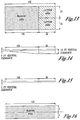
- Fig. 11 shows a warning envelope based on insufficient terrain clearance when the vessel is moving in shallow or coastal waters, for example when in a river channel or approaching a port or harbor.
- an audible "TOO CLOSE GROUNDING" warning is given when the vessel enters region 150 of the graph.
- a warning light or other visual warning indication may also be provided.
- the alerting scheme is reactive and detects encroaching terrain. Predictive alerts are possible when the position of the vessel is known relative to the position of the proximate terrain.
- the following sections detail various predictive alerting schemes which can be utilized with the present invention.
- a predictive alert envelope has dimensions based on the displacements required to execute an evasive maneuver.
- the terrain data is compared to the boundaries of this envelope and if any terrain data is found to be located within the boundaries of the envelope, an alert warning is given of a potential hazard.
- This embodiment of a predictive alerting scheme constructs protection envelopes in the direction of travel of the vessel based upon the last position from which a standard IMO maneuver can be executed to prevent grounding or collision with obstacles.
- This alerting scheme while applicable to all cases, has the advantage of being readily constructed for all vessels since only the ship length need be known to define the envelope dimensions.
- the maximum expected displacements for collision avoidance are: (1) the distance required for a full stop along axis G-X of Fig 3 ; and ( 2 ) the distance equal to the tactical diameter for 180° change of heading.
- the hatched portion of Fig. 12 defines the resulting lateral dimensions of the alerting.
- the semi-circular path that is not cross-hatched represents the path followed during a turn where the diameter is equivalent to the maximum allowable tactical diameter and is therefore excluded from the alerting envelope. Note that a slightly higher safety margin may be achieved if the latter semicircular areas adopted a diameter equal to the IMO upper limit of 4.5 for the advance at 90 degrees heading.
- Fig. 13 One potential mechanism to provide two levels of alerting, namely caution and warning, is depicted in Fig. 13 .
- the first alert (caution) is provided at the initial position when clearance becomes unacceptable if the vessel is heading towards a potential obstacle.
- the second alert is provided at a distance that is equivalent to at least twice the advance at 90 degrees change of heading, and it therefore allows for a safe turn away from obstacles. Note that increasing the magnitude of the entire look-ahead distance may increase the probability of false/nuisance alerts.
- Figs. 14-15 describe the dimensioning of the protection envelope in the vertical plane.
- an under-keel clearance on the order of 2 ft is permissible.
- the minimum permissible clearance thus has a minimum of 2 feet and increases linearly in the longitudinal direction as depicted in Figure 14 .
- the envelope of Figs. 13 and 14 are especially useful when cruising or for operations in unconfined areas.
- the under-keel clearance envelope is preferably modified as shown in Fig. 15 .
- the condition of being in a port/harbor operation can be determined by comparing the ship's position to known ports/harbors or riverways stored in the terrain data base.
- This condition implies that it may be desirable to reduce the width of the lateral warning envelope presented in Fig. 13 in those instances.
- the side reach magnitude is generally less than one ship length.
- the lateral alerting envelope is thus modulated accordingly and is as depicted in Figure 16 . Note that the as the ability to perform a full turn does not exist in a narrow channel, the entire envelope is based on a stopping maneuver and only a single alert (warning) is generated by this envelope. In cases where the channel width is close to or less than 2L, a further reduction of envelope width is preferable, the exact requirements being dictated by local considerations.
- the envelopes described in Figs. 12-16 above can also be applied to verify clearance beneath overhead obstruction such as bridges. In such an application the envelope retains the plan view dimensions for the given location as discussed in connection with Figs. 12 , 13 and 16 .
- the envelope vertical profile can be set at some fixed, nominal value, for example 0.5 feet and need not be reconfigured as a function of location.
- the predictive envelope is based on a constant time to impact.
- the envelope can be defined around each terrain feature, or optionally, with reference to the marine vessel itself. In this instance, whenever the marine vessel track or marine vessel envelope contacts the surface defining the terrain feature a caution and/or warning alert is given.
- Any warning time could be selected.
- depiction of the terrain is described with reference to the teaching of the Bateman 4,646,244 patent.
- the Bateman 4,646,244 patent is incorporated herein by reference for all purposes.
- it has been found that a constant time to impact envelope is too sensitive and may cause nuisance warnings. Consequently, it has been found advantageous to modify the constant time to impact to make it more sensitive when the vessel is heading directly at terrain and less sensitive when the vessel is merely passing by the terrain.
- Figs. 17, 18 and 19 illustrate the creation of a constant time to impact envelope according to one embodiment of the present invention.
- Fig. 17 illustrates a cone 244 defining a terrain feature or obstacle that is being approached by the marine vessel 100.
- the distance that the protection envelope extends is governed by the desired warning time to impact.
- the envelope may be constructed about the terrain feature as represented by cone 244.
- the boundary 244 of the envelope surrounding the terrain extends further from the terrain than for a marine vessel traveling at low speeds.
- the direction of the extension of envelope 244 from the terrain is also determined by the position and heading of the marine vessel.
- the envelope 238 may also be centered on the marine vessel itself as shown in Figs. 18 and 19 .
- the envelope 244 surrounding the terrain remains of fixed geometry and does not vary as a function of distance from the approaching vessel.
- envelope 239 is substantially planar and extends out from vessel 100 at a depth equivalent to the maximum keel depth.
- the width of envelope 239 can be defined by the transfer distance required to complete a turn away from the terrain obstacle.
- envelope 239 is centered on the vessel track 240 and extends out to a distance 242 based on constant time to impact.
- Boundaries 246 of envelope 239 expand with distance from the vessel to account for navigation uncertainties in vessel projected position.
- One possible method of defining side 246 utilizes the inaccuracies in the prediction of the travel path by differentiating the track signal of the marine vessel to provide a rate of change of track direction over time. Using the rate of change in track and the desired warning time to impact, defines the sides 246 of the envelope.
- Envelope 239 is also planar and centered on the vessel in the direction of travel at a depth equivalent to the maximum keel depth.
- the envelopes of Figs. 17 and 18 may also be anchored to the mast height of the vessel to check for overhead obstruction clearance in a manner similar to that described for underwater terrain.
- a protection envelope 244 is also constructed about the obstacle. The boundaries of this envelope may also be configured to operate as described in Fig. 19 .
- the desired warning reaction time used to define the envelope length may be based on a distance for the marine vessel to come to a complete stop before colliding with the terrain. This distance is then used as the boundary of the envelope generated about the terrain. Similarly, the desired warning reaction time may be based on the distance required for the marine vessel to make an evasive maneuver with respect to the terrain. In this embodiment, the stored ship performance characteristics are used to define such a maneuver and calculate the warning time. Based on this warning time data, a minimum distance between the terrain and the marine vessel needed to perform an evasive action is .ascertained. This minimum distance is used as the boundary of the envelope generated about the terrain.
- the protection envelope and the position of the vessel are then compared. If the marine vessel and the terrain are in closer proximity to each other than the area defined by the envelope either both or one of an aural or a visual indication is provided to the crew.
- the envelopes may also be provided to the display generator. The display illustrates to the crew illustrating the proximity of the marine vessel to the surrounding terrain and alerting visually to the crew of any potential dangers.
- alert envelopes are constructed to look down as well as ahead of the vessel.
- protection envelopes described herein have a configurable dimension in the vertical plane and thus define a volume.
- Fig. 20 illustrates caution and warning envelopes obtained using a look-ahead/look-down envelope.
- the apparatus, methods, and computer program products of the present invention according to this embodiment generate both a caution and a warning envelope, 250 and 252, respectively.
- the caution warning envelope 250 is typically generated to provide initial caution alerts to the user of the marine vessel concerning terrain that is proximate to the marine vessel, while the warning envelope 252 is typically generated to provide a more critical indication to the user that the marine vessel is in immediate danger of colliding with the terrain and obstacles and evasive action is required.
- An alert is provided to the crew when terrain/obstacles are located within the boundaries of the caution or warning envelopes.
- the envelopes generated according to this embodiment of the invention eliminate or reduce the number of nuisance alarms likely to occur.
- the caution and warning envelopes typically have a predefined look ahead distances, 254 and 256, that define the distance ahead of the path of the marine vessel in which terrain is analyzed and caution and warning alerts are generated.
- the caution and warning envelopes also include lower boundaries or terrain clearance floor boundaries respectively that define the depth below the marine vessel for which caution and warning alerts are generated. Further detail on the construction of these boundaries is provided below.
- the caution and warning envelopes each have an associated look ahead distance boundary, 254 and 256, respectively, past which caution and warning alerts are not generated.
- the determination of these look ahead distance boundaries is typically based on the operational characteristics of the marine vessel. Specifically, the look ahead distance values for the caution and warning envelopes are typically selected such that the user of the marine vessel will have sufficient time to note the alert and perform an evasive maneuver. The look ahead distance values are also typically restricted in length to avoid generation of nuisance alarms.
- the look-ahead distance is equal to 15 ship lengths or the stopping distance of the vessel as discussed in Section 4.2.1.
- the look ahead distance value (LAD) for the caution envelope may be defined as two times the time needed for the vessel to perform a turn at present speed plus an added reaction time (nominally 10 seconds) for the user to note the alert and initiate the turn, each multiplied by the speed of the vessel.
- the stopping time and turning characteristics of the vessel for use in the calculation of the look ahead distance can be obtained in the manner described in Section 2.0.
- the LAD may also be provided with a configurable upper and lower limit. For example, for large vessels the limit may be set, for example, at 0.5nm at low speeds ( ⁇ 2kts) and 4nm at cruising speed.
- the caution and warning envelopes of the present invention may thus include look ahead distance values based on either the time required to turn the marine vessel or the time required to stop the marine vessel. In some embodiments, however, it may be advantageous to generate separate look ahead distance values, one based on the time to turn the marine vessel and one based on the time to stop the marine vessel. Specifically, depending on the operational parameters of the marine vessel it may take less time to stop the marine vessel than to turn the marine vessel to miss the terrain. For example, if the marine vessel is traveling at a slow speed, turning effectiveness is reduced and it may take less time or distance to stop the marine vessel. As such, in this embodiment, the caution and warning generator generates look ahead distance values based on both the time to turn the marine vessel and to stop the marine vessel and then selects the smaller respective look ahead distance values for both the caution and warning envelopes.
- the look ahead distances 254 and 256 of Fig. 20 extend vertically from a lower value defined by a terrain clearance floor 258,260 referenced from hull maximum depth to a height above the water surface.
- the extent of boundaries 254,256 above the surface is at least equivalent to the maximum ship height or similar value to ensure clearance beneath overhead obstacles.
- terrain clearance floors, 258 and 260 are referenced from the hull maximum depth as obtained according to Section 2.0 to provide clearance from underwater terrain and obstructions.
- the terrain clearance floors relate to a distance ⁇ H below the marine vessel for which caution and warning alerts concerning underlying terrain are generated.
- the terrain clearance floor may be defined with reference to the shoreline or a closest shallow geographic point. Specifically, when the marine vessel is a considerable distance from the shoreline or a shallow geographic point, the depth of the terrain clearance floor below the marine vessel may be deeper, as there is typically less terrain closer to the bottom of the marine vessel that would create nuisance alarms. However, as the marine vessel approaches a known port or moorage contained in the terrain data base, if the depth ⁇ H of the terrain clearance floor is not decreased, the approaching terrain near the shoreline or shallow point will create nuisance alarms.
- the depth of the terrain clearance floor envelopes may be dynamically varied with respect to the marine vessel's proximity to the port such that adequate protection is provided in open waters and channels where collision with terrain is less expected, while nuisance alarms are reduced in moorages and ports where there ocean bottom is rising to meet the land, but where the vessel must nonetheless make way.
- the terrain clearance floor may be in terms of 5 to 10 feet of clearance when the marine vessel is offshore and decreases from 5 to 2 feet as the marine vessel nears port.
- Fig. 21 illustrates graphically an example of the terrain clearance floor for a caution warning envelope for different distances from port.
- the horizontal axis of the graph represents the distance from stored moorage, while the vertical axis represents depth ⁇ H of the terrain clearance floor.
- the graph for the terrain clearance floor of this embodiment includes a first segment 268 that extends from the offset distance 266 out to a distance D. Beyond the distance D, the terrain clearance floor has a constant depth ⁇ H of 10 feet.
- the caution and warning envelopes may further include cut-off boundaries to avoid spurious warnings when the marine vessel passes terrain or obstacles at a relatively close distance. Without the cut-off boundaries, alerts would be generated although the terrain is below the marine vessel and no terrain is ahead of the marine vessel.
- the cut-offboundary 278 begins at a predetermined envelope cut-off offset 280 below the marine vessel and extends in a direction in front of the marine vessel at a predetermined envelope cut-off angle 282.
- the cut-off angle is equal to the angle of the marine vessel plus a configurable predetermined cut-off angle 282.
- the cut-off boundary 278 extends from the cut-off offset 280 in the direction of the cut-off angle 282 in the direction of travel of the marine vessel to a point 284 where it intersects either a caution or warning envelope boundary 286.
- ⁇ is zero.
- the cut-off boundary 278 illustrated in Fig. 22 extends from the cut-off offset 280 along an angle equal to the cut-off angle.
- the boundary for the caution or warning envelope is selected to be the higher of the boundary 286 or cut-off boundary 278.
- the envelope comprises the cut-off boundary 278 to the point 284, where the cut-off boundary intersects the envelope boundary 286. From the point 284, the boundary is envelope boundary 286.
- cut-off boundary becomes the new boundary for the envelope.
- the caution and warning envelopes are discussed in terms of a single vector along the track of the marine vessel.
- the single vector provides acceptable results because the relatively crude resolution of the terrain database stored in the first memory device is based upon the shallowest depth per cell and the natural noisiness of the heading and position information.
- the single vector approach does not take into account various errors, due to, for example, the terrain database, GPS longitude and latitude errors, as well as the heading accuracy.
- the single vector along the track of the marine vessel may be substituted with an array of vectors, as generally shown in Fig. 23 , which takes such errors into account.
- the track vector is identified with the reference numeral 2100 originating at the instantaneous position X 0 , Y 0 .
- a pair of vectors 2212 and 2214 are disposed at a configurable distance D OFF , for example 0.2 nm, along a segment 2216, perpendicular to the vector 2100 at points X 1 , Y 1 and X r , Y r .
- a pair of outside vectors 2218 and 2220, originating at points X 1 , Y 1 and X r , Y r , respectively, are directed at a configurable angle D ALPHA , relative to the vectors 2212 and 2214.
- the configurable angle D ALPHA may be selected as 3°, equivalent to the track accuracy of the GPS.
- DY OFF D OFF * Sin Track
- the coordinates X r , Y r can be determined in a similar manner.
- Optionally copending attorney docket no. 543-99-006 Serial No. 09/496,297 incorporated herein by reference describes a method of trident width expansion which can be adapted to marine applications to obtain the array of vectors.
- the width of the caution and warning envelopes may be defined with reference to the displacements required to complete IMO standard maneuvers as discussed in Section 4.2.1. This dimension can be further modified to account for narrow channels and confined operations as also previously described in Section 4.2.1.
- Another alternate embodiment of the invention utilizes predictions of the vessel's position at future points in time to obtain a projected track of the vessel. This embodiment differs from the previous embodiments described in that it is based on the predicted position vector rather than defining a dynamic protection envelope based on the vessel's current heading and speed. In this embodiment, an unsafe condition is detected when any point along the predicted track intersects the terrain or obstruction.
- the projected track of the vessel is defined by a certain number of points A to F starting from its actual position, as illustrated in Fig. 24 .
- This track is established form the current position of the vessel and its velocity and acceleration vectors in the manner previously described in Section 2.0.
- Uncertainty in position along the projected track may be accounted for by defining a volume around the vessel having the following axes: an uncertainty margin in latitude LAT e , an uncertainty margin in longitude LONG e , and a vertical uncertainty margin Z e (optionally Z e d and Z e h ) to account for uncertainties in the keel depth and optionally the height of the ship.
- the magnitude of Z e is based upon the ship's response to waves presently being encountered by the ship as governed by the ship's sea keeping state equations and that all uncertainty margins account for errors in the measurement/navigation system.
- the volume of uncertainty resulting therefrom is an ellipsoid of revolution as shown in Fig. 25 whose half axes a, b and c are not necessarily equal.
- an uncertainty range is associated with each point along the projected track of the vessel.
- LAT e LONG e
- the vertical projection in the horizontal plane of Fig. 26 results in an uncertainty circle of navigation N (an ellipse in the general case).
- the envelope of these circles in turn defines a projected track envelope EV round the predicted tack PT.
- the length of predicted track PT for purposes of detecting unsafe clearances is configurable, but in a preferred embodiment may be determined using the look ahead distance calculations defined in any of the previous sections and/or by the vessel stopping or turning time.
- Fig. 27 schematically illustrates the progress of the position of the vessel in relation to the grids contained in the local memory.
- the updating of the local memory may be effected by retaining the region wherein the vessel is situated and by updating the three adjoining regions as illustrated in Fig. 27 by a dashed line.
- Figs. 28A and 28B show the square uncertainty surface with maximum dimensions of m x m grids. All the depths are read and only the value of the shallowest depth Z, is retained and added to the uncertainty margin Z e d defined above. The resulting sum, ZTM, is illustrated in dashes. The set of values ZTM on the map will give the theoretical profile beneath the ship, and the alert logic compares this theoretical profile beneath the ship with the anticipated track of the ship.
- the uncertainty marge Z e may be added to the keel depth valve to save on computation.
- the alert logic also checks for clearance with obstacles, such as a bridge, under which the vessel must pass.
- a second set of values ZTM2 is obtained and comprises the uncertainty warning in Z e h , representing the height of the ship summed with the clearance height Z of the obstacle.
- the alert logic compares the anticipated track of the ship with this overhead theoretical profile and outputs a warning signal when a collision possibility is detected.
- both a caution and a warning logic are associated with the curves of Fig. 28A dn 28B. A warning is given when a point of the terrain intersects a sampling point in close proximity to the vessel such that the helmsman must intervene to avoid grounding the vessel or colliding with an overhead obstacle.
- This sampling point can be determined by reference to the point at which a turning or stopping maneuver can be executed.
- a caution is given to forewarn the helmsman that projected track will encounter an obstacle if it is continued as it is and that he must consider an avoidance maneuver.
- the look-ahead distances for the caution and warning sampling points can be determined as described in any of the preceding sections.
- the present invention may optionally be provided with a device and or logic for calculating an avoidance law.
- the invention constructed in accordance with this embodiment may optionally further include an avoidance logic which alerts the crew to a new heading to steer and/or engine setting to avoid collisions. Specifically when a potential conflict is detected using one of the predictive alerting schemes in the manner described above in Sections 4.2 , the invention next checks for an available collision free pathway having an origin point at the present position of the vessel.
- Figs. 29A and 29B illustrate operation of this feature.
- Fig. 29A illustrates operation of the avoidance logic when one of the envelope based methods of Section 4.2.1, 4.2.2, or 4.2.3. is used.
- Fig. 29A shows a plan view wherein the ship's heading is incremented by a nominal step size d ⁇ .
- a protective envelope is constructed as indicated by the boundaries 2180', 2200', LAD', X 1 ', Y 1 ', and X 2 ', Y 2 '. This envelope is checked for terrain clearance in accordance with the methods described in the aforesaid sections.
- Fig 29B illustrates operation of the avoidance logic when the alerting scheme of Section 4.2.4 is used.
- an alternate track PT' is first generated by incrementing the ship's current heading by nominal step size d ⁇ .
- Alternate track PT' as surrounded by envelope EV' is then checked for terrain clearance in accordance with the method described in Section 4.2.4.
- the routine may preferably also consider the performance parameters of the ship.
- a genetic algorithm or other optimization routine well known to those of skill in the art may be used to refine the initial heading guess d ⁇ .
- the optimization routine can be constrained if desired by eliminating non practical or illegal maneuvers. For example, if the data base contains shipping lane information and the avoidance manoeuver places the vessel in the oncoming sea lane, this guess may be eliminated as a valid candidate from the alternate track choices.
- Such tracks which represent an illegal maneuver but do not themselves represent an immediate grounding hazard, may be retained, however, when it proves to comprise the entire set of alternative tracks.
- Candidate tracks that themselves, present a grounding or obstruction hazard are also removed as a candidate track option.
- the optimization routine selects a track with a constraint of minimizing changes in the ship's current heading. This constraint avoids major course corrections and deviations from the intended course of the vessel. If no safe alternate heading can be found during calculation, or if the solution heading approaches 90°, the avoidance logic defaults to recommending a stopping maneuver, course reversal or other operational procedure.
- the avoidance logic in conjunction with the predictive alerting schemes may be of benefit not only in suggesting evasion maneuvers, but also in reducing nuisance alarms.
- the alerting envelope area can be reduced and need not take into account the area of a pre-assumed stopping or turning response to an alert.
- the alerting envelope internal area to each side of the ship can therefore be reduced or eliminated.
- Terrain and obstacles located within the region of the pre-assumed standard evasive maneuver which may have previously generated an erroneous, or nuisance, alert is thereby no longer a factor.
- the reactive and predictive alerts of Sections 4.1 and 4.2 provides tactical information to the ship's crew useful for avoiding potential grounding hazards or collisions.
- the predictive logic of Section 4.2 can also be additionally used in a strategic manner for route proving.
- the intended course or points of intended movement are received as input and any of the logic of Section 4.2 can be used to check for sufficient terrain clearance along the plotted course.
- the invention can further refine the robustness of this check by including the tide data and any known currents (set and drift data) for the estimated time of arrival at points along the route.
- the crew can be alerted to any errors in navigation plotting and/or to areas along the intended course that may present an increased collision hazard.
- the crew can then make a course correction or will alternatively maintain heightened vigilance when traversing these high risk areas.
- a display system is illustrated in Figs. 30-44 .
- the display system 4000 is used to provide a visual indication of the terrain advisory and terrain warning indications discussed above as a function of the current position of the vessel. Background terrain/obstacles information is also provided which provides an indication of significant terrain relative to the current position of the vessel.
- background information may be displayed in terms of predetermined dot patterns whose density varies as a function of the elevation of the terrain relative to the altitude of the vessel.
- Terrain advisory and terrain warning indications may be displayed in solid colors, such as yellow and red, relative to the anticipated track of the vessel.
- the terrain background information as well as the terrain advisory and warning indications may be displayed on a navigational or weather display, normally existing on the bridge, which reduces the cost of the system and obviates the need for extensive modifications to existing displays, such as a navigational and weather radar type display.
- the terrain and obstacle display can be toggled from the existing displays or superimposed on the existing weather/radar display.
- the terrain data is converted to a weather radar format in accordance with any standard digital bus protocol used aborad commercial shipping vessels.
- the terrain data, masked as weather data can then be easily displayed on an existing navigational or a dedicated weather radar display.
- display system 4000 includes a weather radar display or navigational display 36 connected to a control bus 4040 conforming to a predetermined bus standard and a terrain data bus switch 4060.
- the terrain data bus switch 4060 enables selection between terrain data and weather radar data for display.
- data bus switch 4060 includes a common pole 4080 connected to the display 36 by way of a serial display bus 4100.
- One contact 4120 on the data bus switch 4060 is connected to a serial weather data bus 414 and, in turn, to a weather radar R/T unit 4160, which transmits weather radar data over the weather data bus 4140.
- An antenna 4180 provides weather radar data to weather radar R/T unit 4160.
- Weather radar R/T unit 4160 is also connected to control bus 4040, which is used for range and mode data.
- the terrain advisory and terrain warning indications may be converted to "RHO/THETA" format.
- the converted terrain data is then applied to a terrain data serial bus 4200 and connected to a contact 4220 on the data bus switch 4060 to enable selective display of either weather radar or terrain data on display 36.
- Fig. 31 illustrates a preferred embodiment of the invention in which each word 4250 is 1600 bits long and represents one spoke or radial 4260 of the display 36. Normally, 512 spokes or radials 4260 are transmitted for each complete sweep of the display 36. At a transmission rate of, for example, 1 megahertz (MHz), each word 4250 takes about 1.6 milliseconds (msec) to transmit. For 512 spokes, one complete sweep will thus take about 4 seconds.
- MHz megahertz
- the 1600-bit words 4250 include a header 4280 and 512 range bins 4300.
- the header 4208 includes the control data on the control bus 4040 and also includes a 12-bit code representing the antenna scan angle; the angle of the spoke relative to the vessel heading equivalent to an indicator UP direction.
- the range bins 4300 cover the distance from the antenna 4180 to the maximum selected.
- Each of the 512 range bins includes three intensity bits, encoded into colors as indicated in Table II below. TABLE II 3-BIT RANGE CODE COLOR 000 BLACK 100 GREEN 010 YELLOW 110 RED 001 ----- 101 CYAN 011 MAGENTA 111 -----
- display system 4000 is capable of displaying background terrain information as well as terrain threat indications as a function of the current position of the vessel.
- the predictive algorithm of 4.2.3 is used as an example.
- the threat detection algorithm is run along the projected track of the vessel.
- terrain threat indications are typically displayed along the projected track while background terrain is displayed relative to the heading of the vessel.
- the terrain background information is shown on the display 36.
- the depth of the terrain most proximate to the ship is shown as a series of dot patterns whose density varies as a function of the distance between the vessel and the terrain.
- a relatively dense dot pattern 4320 may be used to indicate terrain that is, for example, 2 feet or less below the vessel.
- a medium dense dot pattern 4340 may be used to represent terrain that is 5 feet or less below the vessel, while a lightly dotted pattern 4360 may be used to indicate terrain 10 feet or less below the vessel.
- terrain more than, for example, 20 feet below the vessel is not shown.
- the dots may be displayed in one of the colors indicated in Table II above, for example, yellow (amber).
- port structures 4380 and/or a shipping channel pathway 4389, for example, in green may also be provided.
- the apparent display resolution may be increased by using more than one color along with the variable density dot patterns, for example, as shown in Table III below. TABLE III DOT DENSITY HIGH 3000 0 PATTERN MEDIUM 4000 1000 LOW 5000 2000 COLOR GREEN YELLOW
- the display of a terrain threat indication is illustrated in Fig. 33 .
- the terrain threat indication may be displayed contemporaneously with the background terrain information.
- Terrain advisory and terrain warning indications are displayed in solid shapes 4400 and 4420, respectively, for example, "squares"; the displayed terrain map cells which represent a threat painted solid yellow or red. More particularly, at an aspect ratio for the display of, for example, 3 x 4 (vertical to horizontal), the terrain cells will appear "square", particularly at relatively low-range settings. Colors are used to distinguish between terrain advisory and terrain warning indications. For example, red may be used to represent a terrain warning indication 4420 while yellow or amber is used to represent a terrain advisory indication 4400.
- colored shapes for terrain threat indications and dot patterns of variable density for the terrain background information clutter of the display 4020 is minimized.
- the terrain data base 24 may be stored in a flash ROM 4440 ( Fig. 9 ) for convenience of updates.
- terrain data from the flash ROM 4440 is transferred to a random access memory (RAM) A, identified with the reference numeral 4460.
- RAM A is mapped with terrain data from the flash ROM 4440, centered about the current position of the vessel, as illustrated in Fig. 9 .
- the RAM A is configured as a "wedding cake" as generally illustrated in Fig. 34 and configured such that the finest terrain resolution is near the position of the vessel and the terrain farthest from the vessel position has the lowest resolution.
- the RAM A may be provided with four (4) layers. As shown, the instantaneous vessel position is shown generally centered in layer 1, having the highest resolution. The resolution of layer 2 lies between the resolution of layer 3 and layer 1. Layer 4 (not shown) is provided with a relatively coarse resolution for use in a cruising mode.
- Such a variable resolution display configured as a layered wedding cake, minimizes the memory size of RAM A as well as the processing time.
- the flash ROM 4440 may also be configured similar to a "wedding cake", as generally illustrated in Fig. 9 .
- the terrain data base 24 may be provided with variable resolution. Relatively coarse resolution can be formed by combining finer resolution maps. With such a resolution, the configuration of RAM A may be selected, for example, in accordance with Table IV. Finer resolutions layers may be used if desired, such as near ports. TABLE IV LAYER RESOLUTION LAYER SIZE (MINUTES) (MINUTES) 1 1/2 ⁇ 1/2 32 ⁇ 32 2 1 ⁇ 1 64 ⁇ 64 3 2 ⁇ 2 128 ⁇ 128 4 5 ⁇ 5 REMAINING AREA
- Each layer is generally centered relative to the vessel position as shown in Fig. 34 at the time of the update of RAM A.
- Each layer of the "wedding cake" has its own update boundary.
- layer 1 of the RAM A includes an update boundary 4480.
- the RAM A is updated with new terrain data from the flash ROM 4440 ( Fig. 9 ) as will be discussed in more detail below.
- the terrain data may be stored in files alternative to the format illustrated in Fig. 8A .
- the file format of the terrain data may include an index file or header 55, stored in one or more 128 K byte storage blocks and a plurality of data files 51, as generally shown in Fix.10.
- each index file 55 may include pointers to specific data files 51, the length of the map file, as well as the position of one or more of the corner boundaries of the file 51, for example, northwest and southeast corners of each map file 51, which facilitates updates of the display 36 as a function of the current vessel position.
- the index file 55 may contain information regarding the length of the map file 51, a start of file or altitude offset, the resolution of the map file 51, and whether and how the file 51 is compressed to enable use of various compression algorithms.
- the data files 51 may include a file header 4540 as well as data blocks 4560 shown in Fig. 35 , which, as shown, can be grouped according to resolution size.
- the file header 4540 indicates various information about the file.
- the format of the header 4540 may be structured as follows:
- the major and minor version bytes relate to the revision status of the data in the data files 51.
- the minor version is set as the inverse of the byte value of the major version such that a default erase will indicate a zero version.
- the file status byte 4570 provides various information regarding the status of the file as discussed below, while the attribute byte is reserved.
- the file name, extension file length, and spare data are self-explanatory.
- the time stamp relates to the operational time of the system (i.e. length of time in use) while the CRC data relates to the data files 51.
- the status byte may be used to provide the following information regarding the data blocks 4560, for example, as set forth in Table V below: TABLE 6 FLAG BYTE VALUE INFORMATION FF EMPTY FE DOWNLOADING FO VALID EO READY TO ERASE . RESERVED . RESERVED 00 RESERVED
- the EMPTY status (FF) is set by erasing the data blocks 4560, while the DOWNLOADING status (FE) is set as part of the image.
- the VALID status (FO) is set when the file is loaded.
- the READY TO ERASE (EO) is set by the file system for obsolete blocks.
- various corrections of the data files 51 may be required in areas near ports and shorelines.
- the depths are generally selected to be the shallowest depths within the cells, rounded up to the next highest resolution increment, for example 2 or 54 feet. While such a system provides useful and conservative terrain data for use with the terrain data base 24, such a system in the vicinity of a port or shoreline can cause the elevations of critical features to be too high or too low. Such errors in feature depth can degrade system performance, and, in particular, cause improper performance of the terrain advisory and terrain warning cut-off boundaries.
- the actual depth below mean sea level of the terrain feature is used for cells 4550 around a perimeter of the terrain feature.
- Fig. 36 represents a simplified block diagram for implementation for the display system 4000 in accordance with the present invention.
- Display system 4000 may include a microprocessor, for example, an Intel type 80486, 25 MHz type microprocessor ("486") and an Analog Devices type digital signal processor (DSP).
- the DSP is primarily used for calculating the RHO/THETA conversions to offload the 4860.
- Display system 4000 may have a normal mode and a cruise mode.
- a normal mode display system 4000 displays terrain out to, for example, 10 minutes sailing time, while in cruise mode out to about 1 ⁇ 2 hour of sailing time.
- the background terrain display levels can be lowered by the crew such that terrain, for example 100 feet or 200 feet below the vessel, can be displayed.
- the display level could automatically be adjusted to the highest terrain within the selected display range; the value of this level set forth in amber, for example.
- the 486 runs a "file picker" routine which searches terrain data base 24 for terrain data covering the area relative to the current position of the vessel. For example, in a normal mode, the file picker routine searches the terrain data base 24 for terrain data covering a given area relative to the current position of the vessel. As indicated above, the terrain data base 24 includes index files 55 ( Figs. 8B and 10 ) which may include the northwest and southeast corners of each map file 51 in order to facilitate the search. A list of files covering the area is assembled and maintained.
- Index file 55 also includes information as to whether and how data files 51 are compressed.
- the files may be compressed/decompressed by a modified Huffman code, or techniques known to those of ordinary skill in the art.
- DFR decompressed file RAM
- RAM A identified with the reference number 4460.
- one or two files around the vessel are decompressed and displayed to allow immediate display of a limited range, relative to the position of the vessel. As more terrain data files are decompressed, the additional range is displayed.
- the RAM A may be configured in a plurality of cells 4790, as shown in Fig. 36 , representative of a terrain area 15 arc seconds x 15 arc seconds, with true north appearing at the top of RAM A as shown.
- Each cell 4790 is two bytes wide and includes data regarding the shallowest depth in the cell as well as the identity of each cell 4790.
- the RAM A is addressable by X and Y coordinates and thus represents a map with a depth in each cell 4790.
- the identity of the cell may be used to distinguish between terrain data, for example, from terrain data base 24 and obstacle data. In some applications, an obstacle data base indicating underwater obstructions may be utilized.
- the RAM A may be configured as a wedding cake with various layers, as generally shown in Fig. 34 with the top layer (i.e. layer 1) having the highest resolution. Terrain data is loaded into the RAM A such that the vessel is roughly centered in the top layer, where the terrain advisory and warning detection algorithms are run. Once the vessel moves outside the update boundary 4480 of Fig. 34 , the top layer of the RAM A is reloaded with terrain data with the vessel centered.
- the lower layers may also be provided with update boundaries, which enable the lower layers to be updated independently and less frequently than the top layer.
- the flash ROM 4440 for terrain data base 24 may also be configured as a wedding cake as illustrated in Fig. 34 .
- the highest resolution is provided near ports and shorelines while coarser resolutions are provided elsewhere.
- the terrain data base 24 may be configured with 1° x 1°, 2° x 2° or 10° x 10° map files. Some of the map files may overlap, similar to a "wedding cake.” Maps further away from the port may be provided with resolutions of, for example, 1 x 1 minute or 2 x 2 minutes while a coarse resolution (i.e. 5N x 5N or 10N x 10N) may be provided even further from the port.
- An upload routine may be used to upsample or downsample terrain or obstacle data into the RAM A from the DFR RAM 4760 as shown in Fig.40 .
- Such a routine is well within the ordinary skill in the art.
- the top three layers (i.e. layers 1, 2 and 3) of the RAM A of Fig. 38 are updated from the map file source from the flash ROM 4440 for terrain data base 24 having the highest resolution, except for the 5 x 5 minute layer, which is updated only from a 5 x 5 minute file source to reduce processing time.
- an additional RAM A* may be provided and structured similar to the RAM A 4460, forming a "ping-pong" memory arrangement.
- one terrain data file 51 is decompressed one file at a time and loaded into the DFR RAM 4760 and then upsampled to either the RAM A or RAM A*.
- the terrain threat and display algorithms are executed from the RAM A*.
- the RAM A is then used for the computations while the other RAM A* is updated with new data from the DFR RAM 4760 to account for changes in the vessel position.
- each file includes an index file 55 which contains data relative to the resolution of the terrain data in a particular map file 51.
- index file 55 which contains data relative to the resolution of the terrain data in a particular map file 51.
- Such information can be used to vary the resolution of the map files as a function of longitude and latitude position. For example, the latitude resolutions of the map files can be decreased at higher latitudes in a northward direction.
- longitude resolution in the RAM A can be varied and provided with, for example, a one degree latitude hysteresis to prevent flipping back and forth as a vessel cruises northwardly.
- the threat detection algorithm detects terrain along, for example, the look-ahead vector arrays 4900 and 4920 ( Fig. 23 )
- the offending terrain is painted in an expanded cone around the groundtrack as shown in Fig. 38 .
- the expanded cone includes a plurality of vectors, spaced, for example, 4° apart (configurable value), for 90° (configurable value) on each side of the groundtrack.
- the cone may be expanded out distances, for example as set forth in Table VI below.
- the terrain threat is painted on the display 36 by calculating the starting vector angle DISPA as set forth in equation (29) when a terrain threat along the track has been detected.
- DISPA ANTICIPATED TRACK + 30 degrees
- DELTA X NS DISPLAY STEP SIZE * SIN DISPA * 1 / COS LATITUDE
- DELTA Y NS DISPLAY STEP SIZE * COS DISPA , where the display step size is a configurable constant, for example 1/2 unit.
- the instantaneous position of the vessel X 0 , Y 0 is incremented by the same and the range is incremented by the step size.
- the DEPTH is then determined for the current position on the terrain map.
- the threat detection algorithms are run for the distances as discussed above. Should a threat be detected, a color is loaded into a RAM B, identified with the reference numeral 5040 as shown in Fig. 36 .
- the vector angle DISPA is incremented by 4 degrees with the above steps being repeated until all vectors are done.
- a background terrain algorithm is also executed relative to the terrain data in RAM A of Fig. 36 once every screen update, about 4 seconds.
- the background terrain algorithm simply compares the current altitude of the vessel with the various terrain altitude data in the RAM A.
- Any of the dot patterns 4320, 4340 and 4306 shown in Fig. 32 resulting from the computation are stored in the RAM B organized in a wedding-cake configuration according to Fig. 34 , similar to the RAM A.
- the RAM B is organized in single byte cells containing the color/dot pattern as discussed above.
- the color/dot pattern in the RAM B is transferred to the DSP memory RAM B*, identified with the reference numeral 5060, once per screen update (i.e. 4 sec) and synchronized to the DSP screen painting period. If a threat is detected as discussed above, a new RAM B image is transferred to the DSP RAM B* 5060 immediately. The image transfer time typically fits between two spokes. If not, the DSP will send an old spoke stored in its spoke memory 5080, 5100 twice.
- the DSP then performs the RHO/THETA conversion on the data in RAM B* 5060 using the updated position, selected range and heading data from the 486, as discussed below. Changes in the selected range are implemented on the fly (i.e. the next spoke) without restarting the sweep.
- One possible weather radar format includes 512 spokes covering a configurable scan range of typically 90 degrees and a range selected, for example, on a weather data control panel.
- each spoke is calculated twice, once for the left selected range and once for the right selected range.
- the spokes are then transmitted by way of a serial port 5120, interleaved left spoke and right spoke to bus switch 4060 by way of a pair of drivers 5140 and 5160.
- the resolution of the scan conversion is 256 range bins; each range bin actually being a double range bin per the ARINC 708/453 standard format. Such a resolution is sufficient for the dot patterns illustrated in Figs. 32 and 33 .
- the RHO/THETA conversion is best understood with reference to Fig. 39 .
- the range increment R1 is determined.
- the range increment is the selected range divided by 256.
- the starting spoke angle is determined (e.g.., the vessel true heading plus 90 degrees).
- the incremental spoke angle DELTA ALPHA is determined.
- the incremental spoke angle DELTA ALPHA is the sweep range divided by 512; the total number of spokes per sweep.
- the incremental range coordinates DELTA X ns , DELTA Y ns are computed and the spoke angle is incremented by DELTA ALPHA, as discussed above.
- the incremental range increment coordinates X ns and Y ns are computed in accordance with equations (32) and (33), respectively.
- DELTA X ns RI * SIN SPOKE ANGLE * 1 / COS LATITUDE
- DELTA Y ns RI * COS SPOKE ANGLE
- the instantaneous position X 0 , Y 0 is incremented by DELTA X ns and DELTA Y ns .
- the color/pattern for the new position is looked up and output to the display 36. These steps are repeated for the rest of the spoke.
- the color/pattern of each range bin including the conversion of the longitude to nautical miles (i.e. multiplication by 1/COS (LAT)).
- LAT multiplication by 1/COS
- this computation is performed relative to the true north map coordinate system with the vessel true heading pointing up and the spoke angles referenced to it.
- the second computation addresses each display indicator pixel in order to paint the required dot pattern, relative to the display screen coordinate system.
- the generation of dot pattern is illustrated in Figs. 41-43 .
- the scan conversion is simulated by overlaying each RHO/THETA range bin over a calculated indicator pixel map which includes corrections for display aspect ratio using fractal 8 x 8 dot patterns.
- the fractal patterns corresponding to the variable density dot patterns 4320, 4340 and 4360 of Fig. 32 are illustrated in Fig. 41 .
- the fractal pattern size is selected to be 8 x 8 pixels.
- the densest pattern 4320 includes 1/2, or 32, of the 64 pixels are filled. In the medium density pattern 4340, 16, or 1/4, of the pixels are filled. In the least dense pattern 4364 , 4 or 1/16, of the pixels are filled.
- the display screen is divided into a pixel map, having for example, 256 x 256 pixels 5200.
- the 8 x 8 fractal patterns are overlaid onto the pixel map to provide the variable density dot patterns 4320,4340 and 4360 illustrated in Fig. 32 .
- each spoke is determined at the bottom center of the display 36.
- the starting point corresponds to 120, 0.
- the incremental X and Y coordinates relative to the scan angle ALPHA are determined according to equations (34) and (35).
- DELTA X RI * SIN ALPHA
- the increments DELTA X and DELTA Y are applied to a pair of adders 5220 and 5240, which, in turn, are applied to an X-counter 5260 and a Y-counter 5280.
- the X counter 5260 starts at 128 and counts up if DELTA X > 0. If DELTA X ⁇ 0, the X-counter counts down, indicating a pixel on the left ( Fig. 40 ) of the starting position. Since the starting pixel is at the bottom of the display, the Y-counter 5280 starts at zero and always counts up.
- a range counter 5280 counts up to 256; the maximum number of double range bins.
- the range counter 5280 is driven by an increment clock such that the pattern/color is painted once per range increment. The output indicates whether the pixel is to be painted or left blank.
- the background terrain algorithm determines the particular fractal pattern to be used. This data is applied to the DSP to enable the pixels on the pixel map ( Fig.10 ) to be painted or left blank. In particular, the three least significant bits from the X counter 5260 and Y counter 5280 are used to select the fractal pattern as shown.
- the scan conversion simulation is performed in parallel with the RHO/THETA conversion which determines the color/dot pattern of the range bin to be transmitted.
- the color/dot pattern provided by the RHO/THETA conversion is then overlaid with the fractal dot pattern to determine whether the range bin color should be black or painted to provide the proper dot pattern on the display.
- display 36 may also show the terrain/obstacles in a three dimensional view in the in lieu of, or in addition to the plan view described above.
- Fig. 44 shows one embodiment of display 36 on which terrain 6000 and overhead obstacles 6001 are shown in profile view, color coded to show degree of threat and depicted relative to the position of vessel 100, indicated by a vessel or other suitable symbol.
Abstract
Description
- This invention relates to the prevention of grounding accidents for marine vessels. Grounding accidents in the global shipping fleet are a major source of property loss, costing the industry an estimated $400MM annually in insurance liability on global shipping trade of more than $200 billion. U.S. Coast Guard data from the years 1996-1997 indicate that each year, 1170 vessels (towed barges and tugs counted individually) are involved in groundings, in a total of 758 annual incidents on U.S. shipping lanes and waterways.
- Despite this significant adverse impact on shipping and commercial fleets worldwide, there exist limited systems for prevention of grounding accidents. Most ships are equipped with sonar to monitor the actual depth of the water beneath the hull. However, this device is a reactive system that provides only a current status and does not protect against anticipated conditions present along the instantaneous track of the boat. This device also requires active monitoring by ship's crew to detect a hazardous condition. In military operations, use of the sonar may inadvertently betray the boat's location to enemy vessels.
- Vessels may also be equipped with moving map displays that show the vessel's progress relative to a stored nautical chart. These systems also require the crew to actively monitor the vessel's progress against the chart and to proactively identify hazardous conditions.
- In the aviation industry, various systems have been developed that provide warnings and advisory indications to the pilot of aircraft approaching hazardous terrain. Among such systems are systems generally known as ground proximity warning systems (GPWS) which monitor the flight conditions of an aircraft and provide a warning if flight conditions are such that inadvertent contact with terrain is imminent. Among the flight conditions normally monitored by such systems are radio altitude and rate, barometric altitude and rate, air speed, flap and gear positions. These parameters are monitored and an advisory signal and/or warning signal is generated when the relationship between the parameters is such that terrain impact is likely to occur. Typical examples of such systems are disclosed in
U.S. Patent Nos. 3,715,718 ;3,936,796 ;3,958,218 ;3,944,968 ;3,947,808 ;3,947,810 ;3,934,221 ;3,958,219 ;3,925,751 ;3,934,222 ;4,060,793 ;4,030,065 ;4,215,334 ; and4,319,218 , all assigned to the same assignee as the assignee of the present invention and hereby incorporated by reference.US Patent Nos. 5,488,563 and5,839,080 to Mueller et al. each disclose a controlled flight into terrain alerting system that utilizes a terrain database in conjunction with aircraft dynamics to alert pilots of dangerous proximity to terrain. - However, such systems are designed for aircraft wherein the escape maneuver chiefly consists of adding full power and pitching the aircraft up to initiate a climb. This type of escape from grounding is not available to a surface vessel.
U.S. Patent No. 5,488,563 to Chazelle describes a ground proximity warning system for aircraft that suggests a turning maneuver to escape terrain. However, Chazelle does not disclose or suggest how such a system could be applied to ships, submarines or boats.U.S. Patent No. 4,646,244 to Bateman discloses a terrain alerting methodology for submarines and aircraft. However, Bateman does not disclose terrain alerts for surface ships or terrain avoidance maneuvers. - The present invention includes recognition of the need to provide marine vessels with an alert of conditions that may lead to an inadvertent grounding and/or impact with obstacles in the vessel's path. The alerts provided according to the present invention may be reactive and/or predictive alerts.
- According to one aspect of the present invention, the ship's sonar is utilized to provide an indication of impending impact with bottom obstructions based upon rate of change of water depth beneath the keel.
- According to another aspect of the invention, a ocean bottom terrain data base is provided. The ship's position and anticipated track are compared to the ocean bottom terrain data and an alert is provided when a hazardous condition is detected.
- According to another aspect of the invention, the terrain database includes an obstruction or obstacle data base. The ship maximum height and anticipated track can be compared, for example, with the clearance height required under a bridge obstacle, and an alert provided to the crew if a collision hazard exists.
- According to another aspect of the invention, ocean bottom hazards are displayed on a visual display representative of a plan view of the ocean or waterway bottom terrain. Preferably the terrain is displayed in various colors and/or dot pattern densities depending upon the degree of grounding hazard to the vessel and/or to the degree of obstacle collison hazard. In a preferred embodiment of the invention, the terrain that does not present a hazard to the vessel is displayed in a first color, terrain that is a potential hazard to the vessel is displayed as second color and terrain which represents an immediate and actual danger to the vessel is colored a third color.
- More specifically, the bottom proximity awareness system comprises a navigational system configured to determine latitude, longitude, depth, point of intended movement, velocity, acceleration and/or speed of a vessel employing the system. The navigational system generates signals in response to the listed parameters. The system further comprises: a terrain database comprising depth data for underwater terrain and obstacle information as well as for port facilities; a processor configured to identify from the terrain database depth data within a range of the vessel; warning envelope generator; and a warning device. Further advantages and features of the present invention will be described in detail below.
-
-
Fig. 1 is a top level flow chart illustrating operation of a warning system in accordance with a preferred embodiment of the invention; -
Fig. 2 is a block diagram of a warning system according to a preferred embodiment of the invention; -
Figs. 3A and 3B illustrate a set of coordinates axes and forces useful for understanding ship motions as described in the present application; -
Fig. 4 illustrates a turning maneuver and the nomenclature associated therewith; -
Fig. 5 illustrates a stopping maneuver and the nomenclature associated therewith; -
Fig. 6 illustrates the organization of terrain data into latitude and longitude segments in accordance with a preferred embodiment of the invention; -
Fig. 7 is a graphical representation of the various memory map and resolution sequencing in accordance with the present invention; -
Fig. 8A is an exemplary representation of the digital header and subsquare mask word for identifying geographical areas in accordance with the present invention; -
Fig. 8B is a terrain map alternative toFig. 7 ; -
Fig. 9 is a block diagram illustrating the configuration of a flash ROM for a terrain data base and a RAM used with a preferred embodiment of the present invention; -
Fig.10 is a diagram of the file format of the files in the terrain data base in accordance with a preferred embodiment of the present invention; -
Fig.11 illustrates an insufficient terrain clearance reactive alerting envelope according to a preferred embodiment of the present invention; -
Fig. 12 illustrates a plan view showing the boundaries of an alert envelope according to an embodiment of the present invention; -
Fig. 13 illustrates a plan view of an alert envelope having both caution and warning boundaries according to an embodiment of the present invention; -
Fig. 14 illustrates a side view showing vertical tolerancing of an alert envelope constructed according to an embodiment of the invention; -
Fig. 15 illustrates a side view showing vertical tolerancing of an alert envelope for shallow water operations constructed according to an embodiment of the present invention; -
Fig. 16 illustrates a plan view of an alert envelope for operating in confined spaces according to an embodiment of the present invention; -
Fig. 17 illustrates a constant time to impact alert envelope constructed according to an embodiment of the present invention; -
Fig. 18 illustrates an alert envelope generated with reference to the marine vessel according to an embodiment of the present invention; -
Fig. 19 illustrates an alert envelope based on projected track according to an embodiment of the present invention; -
Fig. 20 illustrates a look ahead/look down alert envelope according to a preferred embodiment of the invention; -
Fig. 21 illustrates a terrain clearance floor as a function of distance from moorage according to a preferred embodiment of the invention; -
Fig. 22 is a graphical illustration of an alert envelope having a cut off boundary according to an embodiment of the present invention; -
Fig. 23 is a plan view of an array of track vectors useful for defining the internal boundaries of the look ahead/look down/look up alert envelopes according to a preferred embodiment of the invention; -
Fig. 24 illustrates a projected track vector according to a preferred embodiment of the present invention; -
Fig. 25 illustrates an ellipsoid of uncertainty in position according to a preferred embodiment of the present invention; -
Fig. 26 illustrates use of ellipsoids of uncertainty about the projected track to obtain an envelope of probable position according to an embodiment of the present invention; -
Fig. 27 illustrates the progress of vessel along the projected track in the local terrain map according to an embodiment of the present invention; -
Fig. 28A illustrates an alert logic along a projected track sampling point according to an embodiment of the present invention; -
Fig. 28B illustrates a plan view of an alert logic along a projected track sampling point according to an embodiment of the present invention; -
Fig. 29A illustrates calculation of an avoidance maneuver in accordance with an embodiment of the present invention; -
Fig. 29B illustrates calculation of an avoidance maneuver using projected track alert envelopes in accordance with an embodiment of the present invention; -
Fig. 30 is a block diagram of a display system according to one embodiment of the present invention; -
Fig. 31 is a functional diagram of the display data format in accordance with a preferred embodiment of the invention; -
Fig. 32 is a plan view of a background terrain display illustrating the variable density dot pattern; -
Fig. 33 is similar toFig. 32 but additionally illustrates the terrain threat indications; -
Fig. 34 illustrates a wedding-cake configuration for a RAM utilized in the present invention; -
Fig. 35 illustrates data blocks constructed according to a preferred embodiment of the present invention; -
Fig. 36 is a block diagram of the display system in accordance with a preferred embodiment of the present invention illustrating the memory configuration and the data flow; -
Fig. 37 is a block diagram of a configuration alternative to that shown inFig. 36 ; -
Fig. 38 is a terrain map illustrating the computation of the hazardous terrain; -
Fig. 39 is a diagram of a terrain map superimposed on a display screen illustrating the sweep range and the determination of the incremental range increments; -
Fig. 40 is a diagram of a pixel map of the display; -
Fig.41 is a diagram of the different fractal patterns used to provide the variable density display of non-hazardous display indications; -
Fig. 42 is a diagram illustrating the determination of the X and Y increments of the display screen; -
Fig. 43 is a diagram of the method for superimposing the fractal patterns on the displayed pixel map; and -
Fig. 44 is a diagram of a three dimensional terrain display according to an embodiment of the present invention; - The present invention now will be described more fully hereinafter with reference to the accompanying drawings, in which preferred embodiments of the invention are shown. This invention may, however, be embodied in many different forms and should not be construed as limited to the embodiments set forth herein; rather, these embodiments are provided so that this disclosure will be thorough and complete, and will fully convey the scope of the invention to those skilled in the art. Like numbers refer to like elements throughout.
-
Fig. 1 contains a flow diagram illustrating the conceptual theory and operation of the present invention. InFig. 1 , symbols representative of the depth and velocity/speed of the vessel, the track of the vessel, and the position of the vessel are received instep 1. Instep 2, search logic, based on the position of the vessel, retrieves terrain and obstacle data relating to terrain and obstacles that are near the vessel current position. Instep 3, based on the position, track, and speed of the marine vessel and the position and depth of terrain and obstacles proximate to the marine vessel, a caution and warning envelope generator generates envelopes either about the vessel or about the surrounding terrain and obstacles. Optionally, and not shown inFig. 1 , the alert may be generated by comparing the closure rate of terrain with a predetermined closure rate limit as described more fully below. The envelopes represent a proximity limitation between the surrounding terrain and obstacles and the marine vessel, such that if the region between the marine vessel and the terrain is less than the envelopes, the marine vessel is in danger of colliding with the terrain. -
Steps step 6 may further include avoidance maneuver guidance. In addition, based on the generated envelopes and the output of the comparison step, appropriate displays may be provided to the crew illustrating the proximity of the marine vessel to the surrounding terrain and obstacles and alerting of any potential dangers. As such, the apparatus, methods, and computer program products of the present invention provide the user of a marine vessel information concerning the proximity of surrounding terrain such that the user may operate the marine vessel with reduced probability of collision or grounding. -
Fig. 2 contains a block diagram of an apparatus for providing terrain proximity alerts to a marine vessel according to one embodiment of the present invention. The apparatus of this embodiment of the present invention includes analert generator 10 having a caution andwarning envelope generator 12 for generating caution and warning envelopes. The apparatus of the present invention also includes anavigation system 14. The navigation system provides the speed/velocity of the marine vessel, the predicted track of the marine vessel, and the position of the marine vessel, (e.g., latitude and longitude) as well as corrections for tides, currents, ship dynamics and keel depth.Apparatus 10 also includes afirst memory device 16 containing coordinate positions of terrain and obstacles, as well as the elevation or depth of the terrain for all or a portion of the global positions of the earth. Additionally, the apparatus of the present invention further includessearch logic 18 for searching the first memory device and retrieving terrain data for terrain that is in proximity to the marine vessel. - A
comparator 20 is coupled to the output ofnavigation system 14 and the caution andwarning envelope generator 12.Comparator 20 receives the caution and warning envelopes generated from the caution and warning envelope generator and the coordinates of the position of the marine vessel from the navigation system. Based on the position of the marine vessel and the envelopes generated by the caution and warning envelope generator, the comparator determines whether the space between the marine vessel and the terrain proximate to the marine vessel is less than the boundaries defined by at least one of the caution and warning envelopes generated by the caution and warning envelope generator. - To notify the user of the proximity of terrain and obstacles to the marine vessel, the apparatus of the present invention further includes a caution and
warning alert generator 22 connected to thecomparator 20 for indicating to the user either aurally by aspeaker 28 and/or visually by alamp 30 of approaching terrain. Additionally, the apparatus of the present invention may also include adisplay generator 23 connected to the output of caution andwarning envelope generator 12.Display generator 23 generates attitude and map displays that are applied to adisplay 36.Display generator 23 controls display 26 to display either or both a side view image showing the terrain and obstacles that lie in the path forward of the track of the marine vessel and a top view of the terrain below the marine vessel. - Signals from
comparator 20 may also be applied todisplay generator 23. These signals permitdisplay generator 23 to indicate whether the distance between the marine vessel and terrain is less than the boundaries defined by the caution and warning envelopes. The terrain threat severity is typically illustrated in the displays by changing the color and/or dot pattern density of the terrain displayed by the display to the user. The elements features and operation of the present invention described briefly above, will now be described in detail below. - In addition to providing apparatus and methods, the present invention also provides computer program products for providing a terrain proximity warning system for use in marine vessels. The computer program products have a computer readable storage medium having computer readable program code means embodied in the medium. In
Fig. 2 , the computer readable storage medium may be part of thememory device 16, and thealert generator 10 of the present invention may implement the computer readable program code means to provide a terrain proximity warning system for use in marine vessels as described in the various embodiments above. - The computer-readable program code means includes first computer instruction means for comparing a current coordinate position of the vessel to a prestored coordinate position of terrain proximate to the vessel and second computer instruction means for providing an alert when the vessel is in a potentially hazardous proximity to the terrain as defined by a predetermined criterion to be described in detail below.
- In some embodiments, the computer-readable program code means further includes computer instruction means for storing a database containing depth data for different global coordinates of the earth. In this embodiment, the first computer instruction means determines the current coordinate position of the vessel and searches the memory device for the prestored coordinate position of terrain proximate to the vessel. The computer-readable program code means may further include a computer instruction means for generating an envelope relative to at least one of the vessel and the proximate terrain. The first computer instruction means determines if the other of the vessel and the terrain penetrates the envelope, and the second computer instruction means provides an alert if the envelope is penetrated.
-
Figs. 1 and2 are flowchart block diagram and control flow illustrations of methods, systems and program products according to the invention. It will be understood that each block or step of the block diagram, flowchart and control flow illustrations, and combinations of blocks in the block diagram, flowchart and control flow illustrations, can be implemented by computer program instructions. These computer program instructions may be loaded onto a computer or other programmable apparatus to produce a machine, such that the instructions which execute on the computer or other programmable apparatus create means for implementing the functions specified in the block diagram, flowchart or control flow block(s) or step(s). These computer program instructions may also be stored in a computer-readable memory that can direct a computer or other programmable apparatus to function in a particular manner, such that the instructions stored in the computer-readable memory produce an article of manufacture including instruction means which implement the function specified in the block diagram, flowchart or control flow block(s) or step(s). The computer program instructions may also be loaded onto a computer or other programmable apparatus to cause a series of operational steps to be performed on the computer or other programmable apparatus to produce a computer implemented process such that the instructions which execute on the computer or other programmable apparatus provide steps for implementing the functions specified in the block diagram, flowchart or control flow block(s) or step(s). - Accordingly, blocks or steps of the block diagram, flowchart or control flow illustrations support combinations of means for performing the specified functions, combinations of steps for performing the specified functions and program instruction means for performing the specified functions. It will also be understood that each block or step of the block diagram, flowchart or control flow illustrations of
Figs. 1 and2 , and combinations of blocks or steps in the block diagram, flowchart or control flow illustrations, can be implemented by special purpose hardware-based computer systems which perform the specified functions or steps, or combinations of special purpose hardware and computer instructions - The present invention receives various inputs and together with stored models of the vessel's characteristics and performance, outputs data useful for computing the bottom proximity alert envelopes. In the block diagram of
Fig. 2 , these operations may be performed byNavigation system 14. The ship's current position may be obtained by reference to onboard navigation systems such as a global positioning system (GPS), inertial navigation system (INS), LORAN, and/or VLF/OMEGA. Optionally, a navigation fix can be manually entered into the ship's navigation system or autopilot by the crew and this information supplied tonavigation system 14. Preferably,navigation system 14 retains the vessel's current position as a set of latitude/longitude coordinates. - While GPS is typically the most advantageous to use as it provides the most accurate data, it must be understood that any particular navigation system may be used. This is typically dependent upon the type of marine vessel. For instance, a military grade marine vessel may include a GPS system for navigation, while a privately owned fishing or water sports craft may include less expensive systems such as a Loran. A combination of systems may also be implemented. Kalman filtering may also be employed to obtain A blended navigation solution based on the various navigation inputs.
-
Navigation system 14 may also use the time derivatives of position information to obtain information on ship speed and course and current present heading, as well as set and drift due to local currents. Such calculations are well known to those of ordinary skill in the art. Optionally,navigation system 14 may receive these inputs directly from other onboard systems, for example, the autopilot, GPS +/- INS, that calculate these values. - The position, data and the data described in the previous paragraph are used to develop an estimate of the vessel's anticipated track and/or the vessel's instantaneous heading and velocity vectors. This data is in turn utilized for the computation of alerts in the manner(s) to be described in more detail below.
-
Navigation system 14 also stores data or retrieves input from other shipboard systems as needed to compute the maximum hull depth. In the case of ships and other surface operated marine vessels, keel depth will vary as a function of the center of gravity, center of buoyancy, and displacement of the vessel. A pressure sensor(s) or other fathometer may also be employed at the keel or along the hull to directly measure the depth below keel or draft of the surface vessel. Such data may therefore include the nominal keel depth, current weight of vessel, consumables and cargo, and moment of inertia data as well as tide tables. The tide tables may be used in conjunction with clock data obtained from the ship's clock or GPS system to compute changes from mean sea level. These changes may be applied either as a correction to the maximum hull depth/height of the vessel or applied as a correction to the depth/height of terrain features. In a preferred embodiment of the invention, the tide correction is applied to the hull depth/height to avoid the numerous calculations necessary to apply this correction to all terrain features. - The invention may also contain data useful for computing vessel motion and performance characteristics. Typical analysis of vessel motion includes analysis of both "calm water" effects as well the vessel sea keeping characteristics. The "calm water" effects are those that are attributable to forces arising from operation of the vessel's control surfaces and propulsion systems. Sea keeping characteristics analyze the vessel motion due to wave action in the frequency domain.
- A preferred embodiment of the invention thus includes a modular six degree of freedom model of vessel behavior. Optionally, a reduced set of equations with fewer degrees of freedom can be used. A reduced set of equations saves computation time and may be sufficient when only the translation and heave motions of the ship need be calculated. For completeness, the complete model may be generically described as given below.

- m is the vessel mass matrix
- U is the vessel speed vector
- X, Y, Z and the surge, heave and sway forces as shown in
Fig. 3 and - u̇, v, r are the angular rates about the axes of
Fig. 3 - Although there are several mathematical models suitable for use with the present invention, the modular approach permits modeling of effects due to propulsion and steering as well as vessel configuration to be easily incorporated. Wilson et al. in Modeling and Control of Marine Craft (Elsevier Applied Science, Pourzanjani and Roberts eds.), incorporated herein by reference for all purposes, describe one set of models suitable for use with the present invention. Specifically, these equations describe the forces X, Y, Z and corresponding moments K, M, N about the orthogonal axes x, y, z. In the analysis to follow, these equations are written with a coordinate system centered on the vessel center of gravity, however, it is to be understood that the invention is not so limited and as known to those of skill in the art, similar equations may be written about any axis, for example the stability, or equilibrium axes. The generalized equations of motion can thus be written as:


- Where r is the angular rate of yaw with respect to time, and u, v are the velocity components of the vessel track as shown in
Fig. 3B . - Direct measurement of the forces X, Y, Z proves difficult in practice and therefore it is customary to expand these equations as set of differential equations written in terms of measurable quantities. These set of equations are sometimes known as the state space equations for the vessel. By way of example, the surge, sway and yaw equations can be expanded to have the form:


- In the preceding equations all terms with subscripts mean partial differentiation with respect to that variable. Some terms in these equations have absolute values. The absolute value operator ensures that the force contribution acts in the correct direction when the vessel is turning. Derivatives are typically in non-dimensional form, relating performance to design parameters such as block coefficient, draft and beam. The nondimensional matrix of coefficients can be determined empirically or analytically during ship design and sea trials. Alternatively, in the absence of vessel specific data, and as is known to those of skill in the art, the various non-dimensional coefficients have been determined for various classes of vessels and can be applied with minimal error to the vessel of interest. Propulsion and thrust effects may also be considered in terms of dimensionless coefficients in the manner taught by Wilson et al. in Pourzanjani and Roberts.
- Maximum hull depth may also vary as a function of the surface vessel's motion in seas. For this reason, the invention may also contain data useful for computing the vessel motion due to wave action. In Probabilistic Theory of Ship Dynamics by Price and Bishop (Wiley and Sons, NY), the authors describe methods for determining the resultant vessel motion using a six column vector of state variables. Specifically, for a rigid ship traveling with constant forward speed
U at an arbitrary angle to regular sinusoidal waves, the resultant motions in the six degrees of freedom are governed by the set of second order linear differential equations written about the ship's equilibrium axes:

- X, Y, Z = amplitudes of surge, sway and heave forces
- K, M, N = amplitudes of roll, pitch and yaw moments
- w e = frequency of wave encounter
- x(t), y(t), z(t) = surge, sway and heave motions
- ϕ(t), θ(t), ψ(t) = variations or roll, pitch and yaw orientations with respect to the equilibrium axes.
- The origin of the body axis in the ship for the sea keeping equations is usually taken at the point of trisection of the midship section, longitudinal plane of symmetry and the waterplane. In general, this origin does not coincide with the center of mass. However, for simplification, it may be assumed that the ship, with lateral symmetry, has a center of mass coincident with the origin of the body axes at the point of trisection. In this event the symmetric 6 x 6 generalized mass matrix m is:

- The elements of 6 x 6 matrix a are a combination of hydrodynamic forces which are in phase with the acceleration of the ship. By analogy with the mass matrix, a is referred to as the 'added mass matrix' with (m + a) is the virtual mass matrix. Physically it may be described very loosely as the quantity of fluid in the vicinity of the ship which is accelerated with the ship. On the other hand, the elements of the 6 x 6 damping matrix b are a combination of hydrodynamic forces which are in phase with the velocity of the ship and are associated with energy dissipation. In an ideal fluid, energy can only be dissipated by the generation and propagation of waves in the free surface.
- For a laterally symmetric ship, the added mass and damping matrices have the forms:

φ ,Kψ are the added hydrodynamic roll moments associated with the roll angular acceleration φ̈(t) and with angular yaw acceleration ψ̈(t) respectively. The quantities Zż and Zθ̇ are the hydrodynamic damping forces associated with the heave velocity ż(t) and with pitch angular velocity θ̇(t), respectively. - Finally the 6 x 6 restoring matrix c accounts for the hydrostatic contributions, although there may be some small additional dynamic effects if the center of mass and origin of the body axes do not coincide. There then exist restoring moments associated with the center of mass of the ship in an angular displacement of the ship. For a harmonically oscillating ship, it is seen that the total hydrodynamic force in phase with the displacement is (- (-ωe 2a+ c) . In effect, there therefore exists some arbitrariness in the definitions of the matrices a and c. On the assumption that c is due to hydrostatic effects only, however, the definitions become unique. For the surface ship, the restoring matrix then has the form:

U from the equations of motion. The quantityU does appear in equations used in the analysis of directional stability and control. - In general, the matrices a, b and c are supposed constant with respect to time but, on the assumption that only the response that is proportional to eiω
e 1 is of interest, some elements are dependent on the frequency of wave encounter ωe. Substituting the foregoing matrices into the initial differential equation yields two sets of coupled equations. One set involves the symmetric motions of surge, heave, pitch and the other involves the antisymmetric motion of roll, sway and yaw. By assuming that the surge motions are an order smaller than the other symmetric motions, a case can be made for simplifying the analysis to the two coupled differential equations involving the pitch and heave motions. In effect, the disturbances of the laterally symmetric ship have been divided into two categories: - a) equations of small symmetric departures from a steady reference motion.
- b) equations of small antisymmetric departures from a steady reference motion.
- The equations describing the coupled motions for heave and pitch due to sea keeping effects are seen to be of the form:


- The quantity T. in the force and moment amplitudes in Table I is defined as:

- While T is the draught of the ship. A simplification to this expression is made by equating T. the mean draught at each section, i.e.

- This approximation holds for sections with regular shaped hulls, but care must be taken when considering, for example, a bulbous bow, sine otherwise errors may be introduced in the evaluated wave exciting force and moments.
- The actual amplitude and frequency of the waves experienced by the vessel when underway, can be calculated iteratively using numerical analysis. In particular, changes in the measured GPS altitude and the time period between such changes may be used to approximate the wave motion for input in to the state equations. As an alternative the vertical accelerations may be measured directly from the INS unit to obtain the wave approximation.
- The complete set of calm water and sea keeping performance equations can thus be solved numerically by the present invention to describe vessel motion and performance and to predict an anticipated track or path if desired. In one preferred embodiment of the invention,
navigation system 14 is utilized for performance of these calculations. The vessel unique data required to obtain the matrices of calm water and sea keeping state space coefficients may be directly input intosystem 10 at the time of installation aboard the ship. Optionally,system 10 may be loaded with a set of data for various classes and/or designs of vessels with this data stored in a look up table memory withinsystem 10 and accessible bynavigation system 14. Whensystem 10 is installed aboard as a line replaceable unit or other hardware device, the category of vessel can then be selected by a programming pin. - Those of ordinary skill in the art will also recognize that the state equations may be integrated over a relatively longer period of time to obtain the kinematics of the ship and obtain a projected track and other predictions of ship performance. Those of skill in the art will further recognize that other formulations of equations describing vessel motion, may also be utilized with the present invention and the invention is not limited to the specific state space models described above. In addition many commercial software packages exist that model ship performance and may be adapted for use with the present invention. One such package called, SIMAN, offered by MARINTEK (www.marimek.sintef.no) of Norway can predict all International Marine Organization (IMO) maneuvers and operational capabilities for single screw/single rudder and twin screw/twin rudder common merchant monohull displacement ships. In addition, SIMAN can calculate crabbing, station keeping, under the influence of wind, wave and current forces.
- Any of the methods described above for predicting the ship motion may also be used to predict ship performance, for example, in a turning maneuver and or stopping distances under various speed, rudder, and screw configurations. The turning performance and stopping distance data can further be utilized to calculate an avoidance maneuver as will also be described below.
- The International Marine Organization (IMO) has also developed a set of standards for turning and stopping based on ship length. These performance standards may be used to ascribe nominal valves to ship performance based on ship length when the actual values are not known.
Figs. 4 and 5 illustrates the displacements for the standard IMO maneuvers. SpecificallyFig. 4 illustrates a turning circle andFig. 5 illustrates a stopping maneuver. The coordinate systems are as given inFigs. 3A and 3B . Specifically, the IMO resolution A.571(18) states that the maneuverability of a ship will be considered satisfactory if the following criteria are met: - Turning ability: the advance should not exceed 4.5 ship lengths and the tactical diameter should not exceed 5 ship lengths in the turning circle maneuver.
- Stopping ability: the track reach in the aster stopping test should not exceed 15 ship lengths.
- Thus in the absence of ship specific performance data useful for solving the equations of motion provided above, the maximum expected displacements for collision avoidance can generically be assumed to be as follows:
- Along G-X - distance to full stop = 15L;
- Along G-Y - tactical diameter at 180 degrees change of heading during a turn = 5L
- For large vessels, wind may have an impact on vessel performance characteristics especially when turning. The influence of wind on ship performance can be incorporated into the state space equations as additional environmental terms in the manner taught by Wilson et al.
- Optionally, each ship typically has a set of advance and transfer tables that describe the forward and lateral distances traveled by the ship in a 90° turn at various speeds. These values are usually determined during sea trials of the vessel by performing turning circles at various speeds. The advance and transfer values for each vessel may be loaded into
system 10 at time of installation for later access bynavigation system 14. - The present invention, for example in
system 10 memory, stores information concerning the position, depth and height of terrain and obstacles for different locations on earth. In this application terrain is used interchangeably to mean both geographic and man made features and obstacles. This information is usually stored in the first memory device as a latitude and longitude with an associated depth or clearance height referenced to mean sea level. There are many different ways and formats in which the position and depth information for the terrain and obstacles could be stored in the first memory device. Data from which to create these databases may be obtained from a variety of sources including NOAA Bathametrics data and/or from digitizing nautical charts. - In one embodiment, in order to save storage space, the terrain and obstacles may be represented by geometric shapes, such as cones, that are superimposed over the terrain and obstacles. These geometric shapes have a height that corresponds approximately to the height of obstacle. As such, each terrain feature or obstacle in the memory device may be defined by a position, height, and width. For example, a mountain or mountain range may be represented by a cone or series of cones illustrating the peak of the mountain or the base of the cone represents the base of the mountain. This method of data storage is described in greater detail in
U.S. Patent No. 4,646,244 to Bateman et al. , "Terrain Advisory System" incorporated herein by reference. As illustrated in the Bateman '244 patent, this method of data storage allows for compaction of the data such that smaller storage devices may be utilized. - In a preferred embodiment of the invention, however, the port data and coastal/waterway data are separated into two
different data bases 26 and 24, respectively, as illustrated inFigs. 6-8 . Such a configuration allows either of the data bases 24 or 26 to be updated without the need to update the other. - Port data base 26 contains various types of information relating to ports, such as channel approaches, buoys, docks, underwater features and obstructions, tides and designation data.
Data base 24 is preferably structured to provide varying resolutions of terrain data as a function of the topography of the terrain, as well as water depth. For example, a relatively high resolution can be provided close to port and to shore while in deeper water, a coarser resolution is sufficient. - Data bases 24 and 26 may be formed from semiconductor storage devices well known to those of skill in the art such as, for example: flash erasable programmable read only memory (ROM) devices, such as a flash EEPROM; or mini hard disk drives, and/or PCMCIA cards which could take advantage of known data compression techniques to reduce the amount of storage space required and also promote easy data retrieval by search algorithm 29.
-
Figs. 6 through 8 illustrate the organization ofdata bases 24 and 26. InFig. 6 the world is divided into a plurality oflatitude bands 50, for example each about 4° wide around the equator such that eachlongitudinal segment 52 is about 256 x 256 nautical miles. In order to maintain a relatively constant segment size, the number oflongitudinal segments 52 perlatitude band 50 are reduced closer to the poles. - Since the number of
latitude bands 50 and the number oflongitudinal segments 52 perlatitude band 50 is fixed, determination of the particular segment corresponding to the current vessel position is readily determined. For example, the vessel current latitude X is used to determine the latitude band number. Next, the number oflongitudinal segments 52 associated with thatband 50 is determined either by way of a LOOK-UP table or by calculation. Once the number oflongitudinal segments 52 in theparticular latitude band 50 of interest is determined, the current longitudinal position Y of the vessel can be used to readily determine the longitudinal segment number. - The minimum data associated with each
longitudinal segment 52 corresponds to the point closest to the surface as defined by the mean sea level within that segment. As mentioned above, each of thesegments 52 is approximately 256 x 256 nautical miles. As shown inFig. 7 ,longitudinal segments 52 are broken down into various subsquares to provide varying levels of resolution. For example, eachsegment 52 may be broken down into a plurality ofsubsquares 54, each subsquare 54 being 64 x 64 nautical miles to provide a very coarse resolution. Thesubsquares 54, can, in turn, be further subdivided into a number ofsubsquares 56, for example, each 16 x16 nautical miles, to provide a coarse resolution. Thesesubsquares 56, in turn, can be subdivided into a plurality ofsubsquares 58, for example each 4 x 4 nautical miles, to provide a medium resolution. Thesubsquare 58 can also be broken down into a plurality ofsubsquares 60, for example 1 x 1 nautical miles, to provide a fine resolution. In the vicinity around ports, it may even be desirable to break down thesubsquares 60 down intosmaller subsquares 62 to provide even finer resolution, for example ¼ x ¼ nautical miles. These segments may be further subdivided as needed to provide the desired resolution. - As shown in
Fig. 8A , the data associated with eachlongitudinal segment 52 comprises aheader 65 which includes a multiple data byte 66 which includes the reference depth which corresponds to the point of least depth for all the subsquares within the segment, which assumes that the highest point in a square is representative of the entire square elevation.Multiple data byte 66 may also include a flag to indicate when no further subdividing is required for certain geographical areas, for example, deep water areas. To facilitate updating the data base on a piecewise basis, multiple data bye 66 may also contain a flag bit or code indicating that data corresponding to further subdivisions does not exist for aparticular segment 52 containing a code indicating that no map data exists in the segment. - For areas having significant underwater terrain and areas in the vicinity of a port, the
longitudinal segments 52 are subdivided as discussed above. In such a situation, the stored data would include a 2-byte mask word 68, which points to the subsquares having different depth data. For example, as shown inFig. 8A , the 2-byte mask word 68 is illustrated with a pointer in thebox 15 within thesubsquare 54 within thelongitudinal segment 52, which represents a different depth which points to the next finer layer of resolution as discussed above. The subsquares each include aheader 70 including a mask as described above to enable a pointer for each subsquare having a different depth to point to the next finer layer until the finest resolution level desired is reached as shown. - The data base structure provides for flexibility as to resolution required and can be constructed on a piecewise basis at different times. As such, the structure contains the entire framework necessary to add new data or modify existing data without changing any of the software. The size of the data base is proportional to the resolution and the size of the area to be covered.
- Alternatively, the world may be divided into a plurality of, for example, 1° x 1° map files or
cells 51 as shown inFig. 8B . The various map files 51 may be formed with variable resolution. More particularly, each of the map files may be subdivided into a plurality ofsubcells 53 with the most significant terrain depth in each subcell indicated, with the resolution of all of the subcells within a particular map file being of the same resolution. - The size of the
subcells 53 is varied to provide varying degrees of resolution. For example, for relatively high resolution, the size of thesubcells 53 may be selected as either 15 x15 arc seconds or 30 x 30 arc seconds. The size of thesubcells 53 may also be varied as a function of the terrain in particular coastal or waterway areas. The size of thesubcells 53 may also be varied as a function of the distance to the nearest port or shoreline. - As discussed below and as illustrated in
Fig. 9 , the data base may be compressed by a compression algorithm and stored in a flash read only memory (ROM). Various compression algorithms already known to those of skill in the art are suitable for this application. The compression algorithm does not form a part of the present invention. - In order to simplify computation, each of the map files includes a
header 55, which includes, inter alia, the resolution of theparticular map file 51 as well as the location of one or more corners, for example, the northwest and southwest corners. Theheaders 55 as well as the map files 51 are discussed in more detail below and illustrated in more detail inFig. 10 . - Information about the ship position and dynamics as described in Section 2.0 are compared to the terrain and obstacle information according to an alert logic designed to alert the crew to potential collision hazards. The alert logic can take one of several forms as described in greater detail in the following sections. Use of the various alert logic schemes is not necessarily mutually exclusive, and can coexist. In alternative embodiments of the invention, the present invention may further include an avoidance guidance logic that advises the crew what actions to take once a potential collision hazard has been detected by the alert logic. The avoidance logic is also described in greater detail below.
- The general basis for the design of the grounding/obstacle avoidance logic is to provide sufficient information to the vessel's crew to avoid groundings or collisions. The alerting logic is preferably consistent with the following objectives:
- (a) Sufficient lateral and under-keel clearance is maintained between current vessel position and surrounding obstacles;
- (b) Short-term lateral and vertical clearances will remain acceptable;
- (c) The initial position at which clearance becomes unacceptable is evident (should the vessel be heading towards a potential obstacle); and
- (d) The last position at which a standard maneuver would prevent grounding if the path remains unchanged in condition (c) is identified above.
- Condition (a) is preferably satisfied with reactive system modes, whereas (b)-(d) can be satisfied by predictive modes. These modes are discussed in greater detail below. Human factors data from collision avoidance studies has shown that predictive type information improves operator performance with respect to averting collisions.
- A first embodiment of the invention utilizes a sonar device to sense the depth of underwater obstructions beneath the vessel. The invention evaluates the time rate of change of the depth soundings and does not require input from the terrain database. When the time rate of change exceeds a predetermined value, an alert is provided to the crew. The alert may be aural, visual or both.
- Such a device as a tool to avoid groundings is mostly applicable to submarines and is less applicable to large surface vessels since the time rate of change of the terrain below a surface going vessel may be far in excess of the surface vessel's ability to conduct a turn for avoidance. Furthermore, terrain such as shallow sand bars and other uncharted obstacles may appear suddenly supplying little time for avoidance. Grounding avoidance may be further complicated when operations in narrow channels compromises maneuverability. While it may appear pointless to alert the crew to an inevitable grounding, the alert may have a significant positive impact on damage control, crew preparedness and other proactive management of the grounding incident.
-
Fig. 11 shows a warning envelope based on insufficient terrain clearance when the vessel is moving in shallow or coastal waters, for example when in a river channel or approaching a port or harbor. In the curve ofFig. 11 an audible "TOO CLOSE GROUNDING" warning is given when the vessel entersregion 150 of the graph. A warning light or other visual warning indication may also be provided. - In the previous section, the alerting scheme is reactive and detects encroaching terrain. Predictive alerts are possible when the position of the vessel is known relative to the position of the proximate terrain. The following sections detail various predictive alerting schemes which can be utilized with the present invention.
- In one embodiment of the invention, a predictive alert envelope has dimensions based on the displacements required to execute an evasive maneuver. The terrain data is compared to the boundaries of this envelope and if any terrain data is found to be located within the boundaries of the envelope, an alert warning is given of a potential hazard.
- This embodiment of a predictive alerting scheme constructs protection envelopes in the direction of travel of the vessel based upon the last position from which a standard IMO maneuver can be executed to prevent grounding or collision with obstacles. This alerting scheme, while applicable to all cases, has the advantage of being readily constructed for all vessels since only the ship length need be known to define the envelope dimensions. Based on the IMO standard maneuvers as described in Section 2.0 and
Figs. 4 and 5 , the maximum expected displacements for collision avoidance are: (1) the distance required for a full stop along axis G-X ofFig 3 ; and (2 ) the distance equal to the tactical diameter for 180° change of heading. - The hatched portion of
Fig. 12 defines the resulting lateral dimensions of the alerting. The semi-circular path that is not cross-hatched represents the path followed during a turn where the diameter is equivalent to the maximum allowable tactical diameter and is therefore excluded from the alerting envelope. Note that a slightly higher safety margin may be achieved if the latter semicircular areas adopted a diameter equal to the IMO upper limit of 4.5 for the advance at 90 degrees heading. - One potential mechanism to provide two levels of alerting, namely caution and warning, is depicted in
Fig. 13 . The first alert (caution) is provided at the initial position when clearance becomes unacceptable if the vessel is heading towards a potential obstacle. The second alert (warning) is provided at a distance that is equivalent to at least twice the advance at 90 degrees change of heading, and it therefore allows for a safe turn away from obstacles. Note that increasing the magnitude of the entire look-ahead distance may increase the probability of false/nuisance alerts. -
Figs. 14-15 describe the dimensioning of the protection envelope in the vertical plane. As known to those of skill in the art, in some ports an under-keel clearance on the order of 2 ft is permissible. The minimum permissible clearance thus has a minimum of 2 feet and increases linearly in the longitudinal direction as depicted inFigure 14 . - The envelope of
Figs. 13 and 14 are especially useful when cruising or for operations in unconfined areas. For port/harbor type operations the under-keel clearance envelope is preferably modified as shown inFig. 15 . The condition of being in a port/harbor operation can be determined by comparing the ship's position to known ports/harbors or riverways stored in the terrain data base. - In those areas (including ports) where the vessel is constrained to maneuver in narrow channels, the possibility may not exist to execute a full turning circle to avoid potential obstacles. This condition implies that it may be desirable to reduce the width of the lateral warning envelope presented in
Fig. 13 in those instances. For initial turn and full stop maneuvers the side reach magnitude is generally less than one ship length. The lateral alerting envelope is thus modulated accordingly and is as depicted inFigure 16 . Note that the as the ability to perform a full turn does not exist in a narrow channel, the entire envelope is based on a stopping maneuver and only a single alert (warning) is generated by this envelope. In cases where the channel width is close to or less than 2L, a further reduction of envelope width is preferable, the exact requirements being dictated by local considerations. - The envelopes described in
Figs. 12-16 above can also be applied to verify clearance beneath overhead obstruction such as bridges. In such an application the envelope retains the plan view dimensions for the given location as discussed in connection withFigs. 12 ,13 and 16 . The envelope vertical profile, however, can be set at some fixed, nominal value, for example 0.5 feet and need not be reconfigured as a function of location. - In an alternative embodiment of the invention the predictive envelope is based on a constant time to impact. The envelope can be defined around each terrain feature, or optionally, with reference to the marine vessel itself. In this instance, whenever the marine vessel track or marine vessel envelope contacts the surface defining the terrain feature a caution and/or warning alert is given. Such a system has the advantage that any warning time could be selected. For purposes of illustration, depiction of the terrain is described with reference to the teaching of the Bateman 4,646,244 patent. The Bateman 4,646,244 patent is incorporated herein by reference for all purposes. Furthermore, in some instances, it has been found that a constant time to impact envelope is too sensitive and may cause nuisance warnings. Consequently, it has been found advantageous to modify the constant time to impact to make it more sensitive when the vessel is heading directly at terrain and less sensitive when the vessel is merely passing by the terrain.
-
Figs. 17, 18 and 19 illustrate the creation of a constant time to impact envelope according to one embodiment of the present invention. Specifically,Fig. 17 illustrates acone 244 defining a terrain feature or obstacle that is being approached by themarine vessel 100. The distance that the protection envelope extends is governed by the desired warning time to impact. In one embodiment the envelope may be constructed about the terrain feature as represented bycone 244. For example, for a marine vessel traveling at a high speed, theboundary 244 of the envelope surrounding the terrain extends further from the terrain than for a marine vessel traveling at low speeds. In addition, the direction of the extension ofenvelope 244 from the terrain is also determined by the position and heading of the marine vessel. - The
envelope 238 may also be centered on the marine vessel itself as shown inFigs. 18 and 19 . In the embodiment ofFigs. 17 and 18 , theenvelope 244 surrounding the terrain remains of fixed geometry and does not vary as a function of distance from the approaching vessel. InFig. 17 ,envelope 239 is substantially planar and extends out fromvessel 100 at a depth equivalent to the maximum keel depth. The width ofenvelope 239 can be defined by the transfer distance required to complete a turn away from the terrain obstacle. - In
Fig. 18 ,envelope 239 is centered on thevessel track 240 and extends out to adistance 242 based on constant time to impact.Boundaries 246 ofenvelope 239 expand with distance from the vessel to account for navigation uncertainties in vessel projected position. One possible method of definingside 246 utilizes the inaccuracies in the prediction of the travel path by differentiating the track signal of the marine vessel to provide a rate of change of track direction over time. Using the rate of change in track and the desired warning time to impact, defines thesides 246 of the envelope.Envelope 239 is also planar and centered on the vessel in the direction of travel at a depth equivalent to the maximum keel depth. - The envelopes of
Figs. 17 and 18 may also be anchored to the mast height of the vessel to check for overhead obstruction clearance in a manner similar to that described for underwater terrain. Aprotection envelope 244 is also constructed about the obstacle. The boundaries of this envelope may also be configured to operate as described inFig. 19 . - The desired warning reaction time used to define the envelope length may be based on a distance for the marine vessel to come to a complete stop before colliding with the terrain. This distance is then used as the boundary of the envelope generated about the terrain. Similarly, the desired warning reaction time may be based on the distance required for the marine vessel to make an evasive maneuver with respect to the terrain. In this embodiment, the stored ship performance characteristics are used to define such a maneuver and calculate the warning time. Based on this warning time data, a minimum distance between the terrain and the marine vessel needed to perform an evasive action is .ascertained. This minimum distance is used as the boundary of the envelope generated about the terrain.
- The protection envelope and the position of the vessel are then compared. If the marine vessel and the terrain are in closer proximity to each other than the area defined by the envelope either both or one of an aural or a visual indication is provided to the crew. The envelopes may also be provided to the display generator. The display illustrates to the crew illustrating the proximity of the marine vessel to the surrounding terrain and alerting visually to the crew of any potential dangers.
- In an additional embodiment of the invention the alert envelopes are constructed to look down as well as ahead of the vessel. As in the embodiment of Section 4.2.1 the protection envelopes described herein have a configurable dimension in the vertical plane and thus define a volume.
-
Fig. 20 illustrates caution and warning envelopes obtained using a look-ahead/look-down envelope. Specifically, the apparatus, methods, and computer program products of the present invention according to this embodiment generate both a caution and a warning envelope, 250 and 252, respectively. Thecaution warning envelope 250 is typically generated to provide initial caution alerts to the user of the marine vessel concerning terrain that is proximate to the marine vessel, while thewarning envelope 252 is typically generated to provide a more critical indication to the user that the marine vessel is in immediate danger of colliding with the terrain and obstacles and evasive action is required. An alert is provided to the crew when terrain/obstacles are located within the boundaries of the caution or warning envelopes. - The envelopes generated according to this embodiment of the invention eliminate or reduce the number of nuisance alarms likely to occur. For instance, as illustrated in
Fig. 20 , the caution and warning envelopes typically have a predefined look ahead distances, 254 and 256, that define the distance ahead of the path of the marine vessel in which terrain is analyzed and caution and warning alerts are generated. Furthermore, the caution and warning envelopes also include lower boundaries or terrain clearance floor boundaries respectively that define the depth below the marine vessel for which caution and warning alerts are generated. Further detail on the construction of these boundaries is provided below. - As illustrated in
Fig. 20 , the caution and warning envelopes each have an associated look ahead distance boundary, 254 and 256, respectively, past which caution and warning alerts are not generated. The determination of these look ahead distance boundaries is typically based on the operational characteristics of the marine vessel. Specifically, the look ahead distance values for the caution and warning envelopes are typically selected such that the user of the marine vessel will have sufficient time to note the alert and perform an evasive maneuver. The look ahead distance values are also typically restricted in length to avoid generation of nuisance alarms. - In a preferred embodiment of the invention, the look-ahead distance is equal to 15 ship lengths or the stopping distance of the vessel as discussed in Section 4.2.1. Optionally, the look ahead distance value (LAD) for the caution envelope may be defined as two times the time needed for the vessel to perform a turn at present speed plus an added reaction time (nominally 10 seconds) for the user to note the alert and initiate the turn, each multiplied by the speed of the vessel.

- The stopping time and turning characteristics of the vessel for use in the calculation of the look ahead distance can be obtained in the manner described in Section 2.0. The LAD may also be provided with a configurable upper and lower limit. For example, for large vessels the limit may be set, for example, at 0.5nm at low speeds (<2kts) and 4nm at cruising speed.
- As detailed above, the caution and warning envelopes of the present invention may thus include look ahead distance values based on either the time required to turn the marine vessel or the time required to stop the marine vessel. In some embodiments, however, it may be advantageous to generate separate look ahead distance values, one based on the time to turn the marine vessel and one based on the time to stop the marine vessel. Specifically, depending on the operational parameters of the marine vessel it may take less time to stop the marine vessel than to turn the marine vessel to miss the terrain. For example, if the marine vessel is traveling at a slow speed, turning effectiveness is reduced and it may take less time or distance to stop the marine vessel. As such, in this embodiment, the caution and warning generator generates look ahead distance values based on both the time to turn the marine vessel and to stop the marine vessel and then selects the smaller respective look ahead distance values for both the caution and warning envelopes.
- In a preferred embodiment, the look ahead distances 254 and 256 of
Fig. 20 extend vertically from a lower value defined by a terrain clearance floor 258,260 referenced from hull maximum depth to a height above the water surface. The extent of boundaries 254,256 above the surface is at least equivalent to the maximum ship height or similar value to ensure clearance beneath overhead obstacles. As shown inFig. 20 , terrain clearance floors, 258 and 260 are referenced from the hull maximum depth as obtained according to Section 2.0 to provide clearance from underwater terrain and obstructions. The terrain clearance floors relate to a distance ΔH below the marine vessel for which caution and warning alerts concerning underlying terrain are generated. - For marine vessels, the terrain clearance floor may may be defined with reference to the shoreline or a closest shallow geographic point. Specifically, when the marine vessel is a considerable distance from the shoreline or a shallow geographic point, the depth of the terrain clearance floor below the marine vessel may be deeper, as there is typically less terrain closer to the bottom of the marine vessel that would create nuisance alarms. However, as the marine vessel approaches a known port or moorage contained in the terrain data base, if the depth ΔH of the terrain clearance floor is not decreased, the approaching terrain near the shoreline or shallow point will create nuisance alarms. As such, the depth of the terrain clearance floor envelopes may be dynamically varied with respect to the marine vessel's proximity to the port such that adequate protection is provided in open waters and channels where collision with terrain is less expected, while nuisance alarms are reduced in moorages and ports where there ocean bottom is rising to meet the land, but where the vessel must nonetheless make way. For example, the terrain clearance floor may be in terms of 5 to 10 feet of clearance when the marine vessel is offshore and decreases from 5 to 2 feet as the marine vessel nears port.
-
Fig. 21 illustrates graphically an example of the terrain clearance floor for a caution warning envelope for different distances from port. The horizontal axis of the graph represents the distance from stored moorage, while the vertical axis represents depth ΔH of the terrain clearance floor. As illustrated, there is typically an initial offsetdistance 266 between the beginning of the envelope and the moorage. This offset is an added distance that accounts for inaccuracies in the position data associated with the stored position for the moorage and the position data indicated by the navigation system as the current position of the marine vessel. Further, the graph for the terrain clearance floor of this embodiment, includes afirst segment 268 that extends from the offsetdistance 266 out to a distance D. Beyond the distance D, the terrain clearance floor has a constant depth ΔH of 10 feet. - In some embodiments of the present invention, the caution and warning envelopes may further include cut-off boundaries to avoid spurious warnings when the marine vessel passes terrain or obstacles at a relatively close distance. Without the cut-off boundaries, alerts would be generated although the terrain is below the marine vessel and no terrain is ahead of the marine vessel. In
Fig. 22 , the cut-offboundary 278 begins at a predetermined envelope cut-off offset 280 below the marine vessel and extends in a direction in front of the marine vessel at a predetermined envelope cut-offangle 282. The cut-off angle is equal to the angle of the marine vessel plus a configurable predetermined cut-offangle 282. For surface operation of a marine vessel, as shown inFig. 22 , the cut-offboundary 278 extends from the cut-off offset 280 in the direction of the cut-offangle 282 in the direction of travel of the marine vessel to apoint 284 where it intersects either a caution orwarning envelope boundary 286. For surface travel, γ is zero. Thus, the cut-offboundary 278 illustrated inFig. 22 extends from the cut-off offset 280 along an angle equal to the cut-off angle. The boundary for the caution or warning envelope is selected to be the higher of theboundary 286 or cut-offboundary 278. Thus, as illustrated inFig. 22 , the envelope comprises the cut-offboundary 278 to thepoint 284, where the cut-off boundary intersects theenvelope boundary 286. From thepoint 284, the boundary isenvelope boundary 286. Thus, if either a caution or warning envelope is below the cut-off boundary, cut-off boundary becomes the new boundary for the envelope. - In the discussion above, the caution and warning envelopes are discussed in terms of a single vector along the track of the marine vessel. The single vector provides acceptable results because the relatively crude resolution of the terrain database stored in the first memory device is based upon the shallowest depth per cell and the natural noisiness of the heading and position information. However, the single vector approach does not take into account various errors, due to, for example, the terrain database, GPS longitude and latitude errors, as well as the heading accuracy. As such, the single vector along the track of the marine vessel may be substituted with an array of vectors, as generally shown in
Fig. 23 , which takes such errors into account. In particular, the track vector is identified with thereference numeral 2100 originating at the instantaneous position X0, Y0. A pair of vectors 2212 and 2214 are disposed at a configurable distance DOFF, for example 0.2 nm, along a segment 2216, perpendicular to thevector 2100 at points X1, Y1 and Xr, Yr. A pair of outside vectors 2218 and 2220, originating at points X1, Y1 and Xr, Yr, respectively, are directed at a configurable angle DALPHA, relative to the vectors 2212 and 2214. The configurable angle DALPHA may be selected as 3°, equivalent to the track accuracy of the GPS. - The coordinates X1, Y1 and Xr, Yr for the vectors 2218 and 2220, respectively, are determined. More particularly, the incremental X and Y vectors, DXOFF and DYOFF, are determined as set forth in the equations below:

factor 1/cos(Latitude) is used to convert DXOFF to nautical miles when DXOFF, DYOFF is in minutes and DOFF is in nautical miles.
- Another alternate embodiment of the invention utilizes predictions of the vessel's position at future points in time to obtain a projected track of the vessel. This embodiment differs from the previous embodiments described in that it is based on the predicted position vector rather than defining a dynamic protection envelope based on the vessel's current heading and speed. In this embodiment, an unsafe condition is detected when any point along the predicted track intersects the terrain or obstruction.
- The projected track of the vessel is defined by a certain number of points A to F starting from its actual position, as illustrated in
Fig. 24 . This track is established form the current position of the vessel and its velocity and acceleration vectors in the manner previously described in Section 2.0. - Uncertainty in position along the projected track may be accounted for by defining a volume around the vessel having the following axes: an uncertainty margin in latitude LATe, an uncertainty margin in longitude LONGe, and a vertical uncertainty margin Ze (optionally Ze
d and Zeh ) to account for uncertainties in the keel depth and optionally the height of the ship. Preferably the magnitude of Ze is based upon the ship's response to waves presently being encountered by the ship as governed by the ship's sea keeping state equations and that all uncertainty margins account for errors in the measurement/navigation system. - The volume of uncertainty resulting therefrom is an ellipsoid of revolution as shown in
Fig. 25 whose half axes a, b and c are not necessarily equal. Thus, as illustrated inFig. 26 , an uncertainty range is associated with each point along the projected track of the vessel. In the explanation to follow, the simplifying assumption is made that LATe = LONGe, Thus, the vertical projection in the horizontal plane ofFig. 26 ,results in an uncertainty circle of navigation N (an ellipse in the general case). The envelope of these circles in turn defines a projected track envelope EV round the predicted tack PT. - The length of predicted track PT for purposes of detecting unsafe clearances is configurable, but in a preferred embodiment may be determined using the look ahead distance calculations defined in any of the previous sections and/or by the vessel stopping or turning time.
-
Fig. 27 schematically illustrates the progress of the position of the vessel in relation to the grids contained in the local memory. The updating of the local memory may be effected by retaining the region wherein the vessel is situated and by updating the three adjoining regions as illustrated inFig. 27 by a dashed line. -
Figs. 28A and 28B show the square uncertainty surface with maximum dimensions of m x m grids. All the depths are read and only the value of the shallowest depth Z, is retained and added to the uncertainty margin Zed defined above. The resulting sum, ZTM, is illustrated in dashes. The set of values ZTM on the map will give the theoretical profile beneath the ship, and the alert logic compares this theoretical profile beneath the ship with the anticipated track of the ship. Optionally, as described above in Section 2.0 the uncertainty marge Ze may be added to the keel depth valve to save on computation. - In yet another embodiment of the invention, the alert logic also checks for clearance with obstacles, such as a bridge, under which the vessel must pass. In this embodiment, a second set of values ZTM2 is obtained and comprises the uncertainty warning in Ze
h , representing the height of the ship summed with the clearance height Z of the obstacle. The alert logic compares the anticipated track of the ship with this overhead theoretical profile and outputs a warning signal when a collision possibility is detected. In a preferred embodiment of the invention, both a caution and a warning logic are associated with the curves ofFig. 28A dn 28B. A warning is given when a point of the terrain intersects a sampling point in close proximity to the vessel such that the helmsman must intervene to avoid grounding the vessel or colliding with an overhead obstacle. The location of this sampling point can be determined by reference to the point at which a turning or stopping maneuver can be executed. A caution is given to forewarn the helmsman that projected track will encounter an obstacle if it is continued as it is and that he must consider an avoidance maneuver. The look-ahead distances for the caution and warning sampling points can be determined as described in any of the preceding sections. - When a possible collision with underwater terrain or overhead obstacles is detected then the present invention may optionally be provided with a device and or logic for calculating an avoidance law.
- The invention constructed in accordance with this embodiment may optionally further include an avoidance logic which alerts the crew to a new heading to steer and/or engine setting to avoid collisions. Specifically when a potential conflict is detected using one of the predictive alerting schemes in the manner described above in Sections 4.2 , the invention next checks for an available collision free pathway having an origin point at the present position of the vessel.
Figs. 29A and 29B illustrate operation of this feature. By way of example,Fig. 29A illustrates operation of the avoidance logic when one of the envelope based methods of Section 4.2.1, 4.2.2, or 4.2.3. is used.Fig. 29A shows a plan view wherein the ship's heading is incremented by a nominal step size dΨ. A protective envelope is constructed as indicated by the boundaries 2180', 2200', LAD', X1', Y1', and X2', Y2'. This envelope is checked for terrain clearance in accordance with the methods described in the aforesaid sections. -
Fig 29B illustrates operation of the avoidance logic when the alerting scheme of Section 4.2.4 is used. InFig.29B , an alternate track PT' is first generated by incrementing the ship's current heading by nominal step size dΨ. Alternate track PT' as surrounded by envelope EV' is then checked for terrain clearance in accordance with the method described in Section 4.2.4. - When selecting alternate track candidates the routine may preferably also consider the performance parameters of the ship. A genetic algorithm or other optimization routine well known to those of skill in the art may be used to refine the initial heading guess dΨ. The optimization routine can be constrained if desired by eliminating non practical or illegal maneuvers. For example, if the data base contains shipping lane information and the avoidance manoeuver places the vessel in the oncoming sea lane, this guess may be eliminated as a valid candidate from the alternate track choices. Such tracks, which represent an illegal maneuver but do not themselves represent an immediate grounding hazard, may be retained, however, when it proves to comprise the entire set of alternative tracks. Candidate tracks that themselves, present a grounding or obstruction hazard are also removed as a candidate track option. Preferably, the optimization routine selects a track with a constraint of minimizing changes in the ship's current heading. This constraint avoids major course corrections and deviations from the intended course of the vessel. If no safe alternate heading can be found during calculation, or if the solution heading approaches 90°, the avoidance logic defaults to recommending a stopping maneuver, course reversal or other operational procedure.
- Use of the avoidance logic in conjunction with the predictive alerting schemes may be of benefit not only in suggesting evasion maneuvers, but also in reducing nuisance alarms. For example, if the vessel is operating in confined areas such as a river bend or canyon, the alerting envelope area can be reduced and need not take into account the area of a pre-assumed stopping or turning response to an alert. The alerting envelope internal area to each side of the ship can therefore be reduced or eliminated. Terrain and obstacles located within the region of the pre-assumed standard evasive maneuver which may have previously generated an erroneous, or nuisance, alert is thereby no longer a factor.
- The reactive and predictive alerts of Sections 4.1 and 4.2 provides tactical information to the ship's crew useful for avoiding potential grounding hazards or collisions. The predictive logic of Section 4.2 can also be additionally used in a strategic manner for route proving. In such an embodiment, the intended course or points of intended movement are received as input and any of the logic of Section 4.2 can be used to check for sufficient terrain clearance along the plotted course. The invention can further refine the robustness of this check by including the tide data and any known currents (set and drift data) for the estimated time of arrival at points along the route. In this manner, the crew can be alerted to any errors in navigation plotting and/or to areas along the intended course that may present an increased collision hazard. The crew can then make a course correction or will alternatively maintain heightened vigilance when traversing these high risk areas.
- A display system, generally identified with the
reference numeral 4000, is illustrated inFigs. 30-44 . Thedisplay system 4000 is used to provide a visual indication of the terrain advisory and terrain warning indications discussed above as a function of the current position of the vessel. Background terrain/obstacles information is also provided which provides an indication of significant terrain relative to the current position of the vessel. - In order to declutter the display, background information may be displayed in terms of predetermined dot patterns whose density varies as a function of the elevation of the terrain relative to the altitude of the vessel. Terrain advisory and terrain warning indications may be displayed in solid colors, such as yellow and red, relative to the anticipated track of the vessel.
- The terrain background information as well as the terrain advisory and warning indications may be displayed on a navigational or weather display, normally existing on the bridge, which reduces the cost of the system and obviates the need for extensive modifications to existing displays, such as a navigational and weather radar type display. The terrain and obstacle display can be toggled from the existing displays or superimposed on the existing weather/radar display. In particular, the terrain data is converted to a weather radar format in accordance with any standard digital bus protocol used aborad commercial shipping vessels. The terrain data, masked as weather data, can then be easily displayed on an existing navigational or a dedicated weather radar display.
- As shown in
Fig. 30 ,display system 4000 includes a weather radar display ornavigational display 36 connected to a control bus 4040 conforming to a predetermined bus standard and a terraindata bus switch 4060. The terraindata bus switch 4060 enables selection between terrain data and weather radar data for display. More particularly,data bus switch 4060 includes acommon pole 4080 connected to thedisplay 36 by way of aserial display bus 4100. Onecontact 4120 on thedata bus switch 4060 is connected to a serial weather data bus 414 and, in turn, to a weather radar R/T unit 4160, which transmits weather radar data over theweather data bus 4140. - An
antenna 4180 provides weather radar data to weather radar R/T unit 4160. Weather radar R/T unit 4160 is also connected to control bus 4040, which is used for range and mode data. - To facilitate compatibility with existing radar displays, which sweep out data over an arc, the terrain advisory and terrain warning indications, as well as the background information discussed above, may be converted to "RHO/THETA" format. The converted terrain data is then applied to a terrain data
serial bus 4200 and connected to acontact 4220 on thedata bus switch 4060 to enable selective display of either weather radar or terrain data ondisplay 36. -
Fig. 31 , illustrates a preferred embodiment of the invention in which eachword 4250 is 1600 bits long and represents one spoke or radial 4260 of thedisplay 36. Normally, 512 spokes orradials 4260 are transmitted for each complete sweep of thedisplay 36. At a transmission rate of, for example, 1 megahertz (MHz), eachword 4250 takes about 1.6 milliseconds (msec) to transmit. For 512 spokes, one complete sweep will thus take about 4 seconds. - The 1600-
bit words 4250 include aheader range bins 4300. The header 4208 includes the control data on the control bus 4040 and also includes a 12-bit code representing the antenna scan angle; the angle of the spoke relative to the vessel heading equivalent to an indicator UP direction. Therange bins 4300 cover the distance from theantenna 4180 to the maximum selected. Each of the 512 range bins includes three intensity bits, encoded into colors as indicated in Table II below.TABLE II 3-BIT RANGE CODE COLOR 000 BLACK 100 GREEN 010 YELLOW 110 RED 001 ----- 101 CYAN 011 MAGENTA 111 ----- - As will be discussed in more detail below,
display system 4000 is capable of displaying background terrain information as well as terrain threat indications as a function of the current position of the vessel. For convenience, where a specific example is desirable to illustrate the display of tactical terrain/obstacle alerts according to the invention, the predictive algorithm of 4.2.3 is used as an example. The threat detection algorithm is run along the projected track of the vessel. Thus, terrain threat indications are typically displayed along the projected track while background terrain is displayed relative to the heading of the vessel. - In
Fig. 32 , the terrain background information is shown on thedisplay 36. As will be discussed in more detail below, the depth of the terrain most proximate to the ship is shown as a series of dot patterns whose density varies as a function of the distance between the vessel and the terrain. For example, a relativelydense dot pattern 4320 may be used to indicate terrain that is, for example, 2 feet or less below the vessel. A mediumdense dot pattern 4340 may be used to represent terrain that is 5 feet or less below the vessel, while a lightlydotted pattern 4360 may be used to indicateterrain 10 feet or less below the vessel. In order to declutter the display 4020, terrain more than, for example, 20 feet below the vessel, is not shown. The dots may be displayed in one of the colors indicated in Table II above, for example, yellow (amber). In addition, in the vicinity of a port or known waterway,port structures 4380 and/or ashipping channel pathway 4389, for example, in green, may also be provided. The apparent display resolution may be increased by using more than one color along with the variable density dot patterns, for example, as shown in Table III below.TABLE III DOT DENSITY HIGH 3000 0 PATTERN MEDIUM 4000 1000 LOW 5000 2000 COLOR GREEN YELLOW - The display of a terrain threat indication is illustrated in
Fig. 33 . As shown, the terrain threat indication may be displayed contemporaneously with the background terrain information. Terrain advisory and terrain warning indications are displayed insolid shapes terrain warning indication 4420 while yellow or amber is used to represent aterrain advisory indication 4400. By using colored shapes for terrain threat indications and dot patterns of variable density for the terrain background information, clutter of the display 4020 is minimized. - The terrain data from the
terrain data base 24, for example, as illustrated inFig. 8 , is used to compute the terrain threat indications as well as background information for thedisplay 36. As discussed above, theterrain data base 24 may be stored in a flash ROM 4440 (Fig. 9 ) for convenience of updates. In order to facilitate update of thedisplay 36 as a function of the position of the vessel, terrain data from theflash ROM 4440 is transferred to a random access memory (RAM) A, identified with thereference numeral 4460. As will be discussed in more detail below, the RAM A is mapped with terrain data from theflash ROM 4440, centered about the current position of the vessel, as illustrated inFig. 9 . - In order to provide a relatively large display range, while minimizing processing time as well as the size of the RAM A, the RAM A is configured as a "wedding cake" as generally illustrated in
Fig. 34 and configured such that the finest terrain resolution is near the position of the vessel and the terrain farthest from the vessel position has the lowest resolution. For example, the RAM A may be provided with four (4) layers. As shown, the instantaneous vessel position is shown generally centered inlayer 1, having the highest resolution. The resolution oflayer 2 lies between the resolution oflayer 3 andlayer 1. Layer 4 (not shown) is provided with a relatively coarse resolution for use in a cruising mode. - Such a variable resolution display, configured as a layered wedding cake, minimizes the memory size of RAM A as well as the processing time. In order to improve the performance of the system, the
flash ROM 4440 may also be configured similar to a "wedding cake", as generally illustrated inFig. 9 . - As discussed above, the
terrain data base 24 may be provided with variable resolution. Relatively coarse resolution can be formed by combining finer resolution maps. With such a resolution, the configuration of RAM A may be selected, for example, in accordance with Table IV. Finer resolutions layers may be used if desired, such as near ports.TABLE IV LAYER RESOLUTION LAYER SIZE (MINUTES) (MINUTES) 1 1/2 × 1/2 32 × 32 2 1 × 1 64 × 64 3 2 × 2 128 × 128 4 5 × 5 REMAINING AREA - Each layer is generally centered relative to the vessel position as shown in
Fig. 34 at the time of the update of RAM A. Each layer of the "wedding cake" has its own update boundary. For example,layer 1 of the RAM A includes anupdate boundary 4480. As the vessel passes through theupdate boundary 4480, the RAM A is updated with new terrain data from the flash ROM 4440 (Fig. 9 ) as will be discussed in more detail below. - Because of the refresh rates required for the
display 36, the terrain data may be stored in files alternative to the format illustrated inFig. 8A . For example, the file format of the terrain data may include an index file orheader 55, stored in one or more 128 K byte storage blocks and a plurality of data files 51, as generally shown in Fix.10. - As shown, each
index file 55 may include pointers to specific data files 51, the length of the map file, as well as the position of one or more of the corner boundaries of thefile 51, for example, northwest and southeast corners of eachmap file 51, which facilitates updates of thedisplay 36 as a function of the current vessel position. Theindex file 55 may contain information regarding the length of themap file 51, a start of file or altitude offset, the resolution of themap file 51, and whether and how thefile 51 is compressed to enable use of various compression algorithms. - The data files 51 may include a
file header 4540 as well as data blocks 4560 shown inFig. 35 , which, as shown, can be grouped according to resolution size. Thefile header 4540 indicates various information about the file. The format of theheader 4540 may be structured as follows: - <MAJOR VERSION BYTE><MINOR VERSION BYTE><FILE STATUS BYTE><ATTRIB BYTE>
- <FILE NAME (8 CHARACTERS)><EXTENSION (4 CHARACTERS)>
- <FILE LENGTH LONGWORD>
- <TIME STAMP LONGWORD>
- <CRC LONGWORD>
- <SPME LONGWORD>
- The major and minor version bytes relate to the revision status of the data in the data files 51. The minor version is set as the inverse of the byte value of the major version such that a default erase will indicate a zero version. The file status byte 4570 provides various information regarding the status of the file as discussed below, while the attribute byte is reserved. The file name, extension file length, and spare data are self-explanatory. The time stamp relates to the operational time of the system (i.e. length of time in use) while the CRC data relates to the data files 51. The status byte may be used to provide the following information regarding the data blocks 4560, for example, as set forth in Table V below:
TABLE 6 FLAG BYTE VALUE INFORMATION FF EMPTY FE DOWNLOADING FO VALID EO READY TO ERASE . RESERVED . RESERVED 00 RESERVED - The EMPTY status (FF) is set by erasing the data blocks 4560, while the DOWNLOADING status (FE) is set as part of the image. The VALID status (FO) is set when the file is loaded. The READY TO ERASE (EO) is set by the file system for obsolete blocks.
- As indicated below, various corrections of the data files 51 may be required in areas near ports and shorelines. The depths, as discussed above, are generally selected to be the shallowest depths within the cells, rounded up to the next highest resolution increment, for example 2 or 54 feet. While such a system provides useful and conservative terrain data for use with the
terrain data base 24, such a system in the vicinity of a port or shoreline can cause the elevations of critical features to be too high or too low. Such errors in feature depth can degrade system performance, and, in particular, cause improper performance of the terrain advisory and terrain warning cut-off boundaries. - In order to solve this problem, the actual depth below mean sea level of the terrain feature, rounded to the nearest resolution, is used for
cells 4550 around a perimeter of the terrain feature. -
Fig. 36 represents a simplified block diagram for implementation for thedisplay system 4000 in accordance with the present invention.Display system 4000 may include a microprocessor, for example, an Intel type 80486, 25 MHz type microprocessor ("486") and an Analog Devices type digital signal processor (DSP). The DSP is primarily used for calculating the RHO/THETA conversions to offload the 4860. -
Display system 4000 may have a normal mode and a cruise mode. In a normal mode,display system 4000 displays terrain out to, for example, 10 minutes sailing time, while in cruise mode out to about ½ hour of sailing time. In the cruise mode, it is contemplated that the background terrain display levels can be lowered by the crew such that terrain, for example 100 feet or 200 feet below the vessel, can be displayed. Alternatively, the display level could automatically be adjusted to the highest terrain within the selected display range; the value of this level set forth in amber, for example. - The 486 runs a "file picker" routine which searches
terrain data base 24 for terrain data covering the area relative to the current position of the vessel. For example, in a normal mode, the file picker routine searches theterrain data base 24 for terrain data covering a given area relative to the current position of the vessel. As indicated above, theterrain data base 24 includes index files 55 (Figs. 8B and10 ) which may include the northwest and southeast corners of eachmap file 51 in order to facilitate the search. A list of files covering the area is assembled and maintained. -
Index file 55 also includes information as to whether and how data files 51 are compressed. The files may be compressed/decompressed by a modified Huffman code, or techniques known to those of ordinary skill in the art. - If data files 51 are compressed, the files are decompressed in the background because of the relatively long decompression time and stored in a decompressed file RAM (DFR) 4760, for example 256 words. The decompressed files are then transferred to RAM A, identified with the
reference number 4460. On power-up, one or two files around the vessel are decompressed and displayed to allow immediate display of a limited range, relative to the position of the vessel. As more terrain data files are decompressed, the additional range is displayed. - The RAM A may be configured in a plurality of
cells 4790, as shown inFig. 36 , representative of aterrain area 15 arc seconds x 15 arc seconds, with true north appearing at the top of RAM A as shown. Eachcell 4790 is two bytes wide and includes data regarding the shallowest depth in the cell as well as the identity of eachcell 4790. As such, the RAM A is addressable by X and Y coordinates and thus represents a map with a depth in eachcell 4790. The identity of the cell may be used to distinguish between terrain data, for example, fromterrain data base 24 and obstacle data. In some applications, an obstacle data base indicating underwater obstructions may be utilized. - As indicated above, the RAM A may be configured as a wedding cake with various layers, as generally shown in
Fig. 34 with the top layer (i.e. layer 1) having the highest resolution. Terrain data is loaded into the RAM A such that the vessel is roughly centered in the top layer, where the terrain advisory and warning detection algorithms are run. Once the vessel moves outside theupdate boundary 4480 ofFig. 34 , the top layer of the RAM A is reloaded with terrain data with the vessel centered. The lower layers may also be provided with update boundaries, which enable the lower layers to be updated independently and less frequently than the top layer. - As discussed above and illustrated in
Fig. 9 , theflash ROM 4440 forterrain data base 24 may also be configured as a wedding cake as illustrated inFig. 34 . In such an implementation, the highest resolution is provided near ports and shorelines while coarser resolutions are provided elsewhere. For example, as illustrated inFig. 37 , theterrain data base 24 may be configured with 1° x 1°, 2° x 2° or 10° x 10° map files. Some of the map files may overlap, similar to a "wedding cake." Maps further away from the port may be provided with resolutions of, for example, 1 x 1 minute or 2 x 2 minutes while a coarse resolution (i.e. 5N x 5N or 10N x 10N) may be provided even further from the port. - An upload routine may be used to upsample or downsample terrain or obstacle data into the RAM A from the
DFR RAM 4760 as shown inFig.40 . Such a routine is well within the ordinary skill in the art. The top three layers (i.e. layers 1, 2 and 3) of the RAM A ofFig. 38 are updated from the map file source from theflash ROM 4440 forterrain data base 24 having the highest resolution, except for the 5 x 5 minute layer, which is updated only from a 5 x 5 minute file source to reduce processing time. - Alternatively, as shown in
Fig. 37 , an additional RAM A*, identified with thereference numeral 4770, may be provided and structured similar to theRAM A 4460, forming a "ping-pong" memory arrangement. In this embodiment, one terrain data file 51 is decompressed one file at a time and loaded into theDFR RAM 4760 and then upsampled to either the RAM A or RAM A*. For example, while the RAM A is being loaded with additional decompressed files, the terrain threat and display algorithms are executed from the RAM A*. Once the RAM A is updated, the RAM A is then used for the computations while the other RAM A* is updated with new data from theDFR RAM 4760 to account for changes in the vessel position. - The 5 x 5 minute resolution layer is primarily intended for use in a cruise mode to provide a look-ahead range of about a half hour. As was illustrated in
Fig. 10 , each file includes anindex file 55 which contains data relative to the resolution of the terrain data in aparticular map file 51. Such information can be used to vary the resolution of the map files as a function of longitude and latitude position. For example, the latitude resolutions of the map files can be decreased at higher latitudes in a northward direction. Moreover, longitude resolution in the RAM A can be varied and provided with, for example, a one degree latitude hysteresis to prevent flipping back and forth as a vessel cruises northwardly. Once the terrain data fromterrain data base 24 is loaded into the RAM A, the terrain advisory and warning algorithms ("detection algorithms") are run, for example, at once per second. - Whenever the threat detection algorithm detects terrain along, for example, the look-ahead vector arrays 4900 and 4920 (
Fig. 23 ), the offending terrain is painted in an expanded cone around the groundtrack as shown inFig. 38 . In particular, the expanded cone includes a plurality of vectors, spaced, for example, 4° apart (configurable value), for 90° (configurable value) on each side of the groundtrack. For an expanded terrain warning, the cone may be expanded out distances, for example as set forth in Table VI below.TABLE VI (For an expansion factor of 2) NORMAL EXPANDED TYPE OF THREAT LOOK-AHEAD/ LOOK-DOWN LOOK-UP LOOK-AHEAD/ LOOK-DOWN LOOK-UP ADVISORY 1.0* 2.0* 2.0* 4.0* LAD LAD LAD LAD WARNING 0.5* 1.5* 1.0* 3.0* LAD LAD LAD LAD - The terrain threat is painted on the
display 36 by calculating the starting vector angle DISPA as set forth in equation (29) when a terrain threat along the track has been detected.
- The range increments are then determined as set forth in equations (30) and (31).


- After the range increments DELTA XNS and DELTA YNS are determined, the instantaneous position of the vessel X0, Y0 is incremented by the same and the range is incremented by the step size. The DEPTH is then determined for the current position on the terrain map. Subsequently, the threat detection algorithms are run for the distances as discussed above. Should a threat be detected, a color is loaded into a RAM B, identified with the
reference numeral 5040 as shown inFig. 36 . At the end of the yellow andred threat vectors - In addition to the terrain detection and display algorithms, a background terrain algorithm is also executed relative to the terrain data in RAM A of
Fig. 36 once every screen update, about 4 seconds. The background terrain algorithm simply compares the current altitude of the vessel with the various terrain altitude data in the RAM A. Any of thedot patterns Fig. 32 resulting from the computation are stored in the RAM B organized in a wedding-cake configuration according toFig. 34 , similar to the RAM A. In addition, the RAM B is organized in single byte cells containing the color/dot pattern as discussed above. - The color/dot pattern in the RAM B is transferred to the DSP memory RAM B*, identified with the
reference numeral 5060, once per screen update (i.e. 4 sec) and synchronized to the DSP screen painting period. If a threat is detected as discussed above, a new RAM B image is transferred to the DSP RAM B* 5060 immediately. The image transfer time typically fits between two spokes. If not, the DSP will send an old spoke stored in itsspoke memory - The DSP then performs the RHO/THETA conversion on the data in RAM B* 5060 using the updated position, selected range and heading data from the 486, as discussed below. Changes in the selected range are implemented on the fly (i.e. the next spoke) without restarting the sweep.
- One possible weather radar format includes 512 spokes covering a configurable scan range of typically 90 degrees and a range selected, for example, on a weather data control panel. In a preferred embodiment, each spoke is calculated twice, once for the left selected range and once for the right selected range. The spokes are then transmitted by way of a
serial port 5120, interleaved left spoke and right spoke tobus switch 4060 by way of a pair ofdrivers - The resolution of the scan conversion is 256 range bins; each range bin actually being a double range bin per the ARINC 708/453 standard format. Such a resolution is sufficient for the dot patterns illustrated in
Figs. 32 and33 . - The RHO/THETA conversion is best understood with reference to
Fig. 39 . In particular, once per sweep (i.e. every 4 seconds) the range increment R1 is determined. The range increment is the selected range divided by 256. After the range increment is determined, the starting spoke angle is determined (e.g.., the vessel true heading plus 90 degrees). The incremental spoke angle DELTA ALPHA is determined. The incremental spoke angle DELTA ALPHA is the sweep range divided by 512; the total number of spokes per sweep. - Once per spoke (i.e. 512 times per 4 second sweep), the incremental range coordinates DELTA Xns, DELTA Yns are computed and the spoke angle is incremented by DELTA ALPHA, as discussed above. The incremental range increment coordinates Xns and Yns are computed in accordance with equations (32) and (33), respectively.


- Once per range increment (i.e. 512 x 256 times per 4 second sweep), the instantaneous position X0, Y0 is incremented by DELTA Xns and DELTA Yns. The color/pattern for the new position is looked up and output to the
display 36. These steps are repeated for the rest of the spoke. - With the use of the DSP, two computations can be done in parallel. In particular, the color/pattern of each range bin including the conversion of the longitude to nautical miles (i.e. multiplication by 1/COS (LAT)). With reference to
Fig. 39 , this computation is performed relative to the true north map coordinate system with the vessel true heading pointing up and the spoke angles referenced to it. The second computation addresses each display indicator pixel in order to paint the required dot pattern, relative to the display screen coordinate system. - The generation of dot pattern is illustrated in
Figs. 41-43 . In general, the scan conversion is simulated by overlaying each RHO/THETA range bin over a calculated indicator pixel map which includes corrections for display aspect ratio using fractal 8 x 8 dot patterns. The fractal patterns corresponding to the variabledensity dot patterns Fig. 32 are illustrated inFig. 41 . The fractal pattern size is selected to be 8 x 8 pixels. Thedensest pattern 4320 includes 1/2, or 32, of the 64 pixels are filled. In themedium density pattern dense pattern - As illustrated in
Fig. 40 , the display screen is divided into a pixel map, having for example, 256 x 256pixels 5200. As mentioned above, the 8 x 8 fractal patterns are overlaid onto the pixel map to provide the variabledensity dot patterns Fig. 32 . - The computation of the dot patterns is best understood with reference to
Figs. 40 ,42 and 43 . Using an X-Y coordinate system, each spoke is determined at the bottom center of thedisplay 36. For a 256 x 256 pixel display, the starting point corresponds to 120, 0. Next, the incremental X and Y coordinates relative to the scan angle ALPHA are determined according to equations (34) and (35).

starting point - In
Fig. 43 , the increments DELTA X and DELTA Y are applied to a pair ofadders counter 5280. TheX counter 5260 starts at 128 and counts up if DELTA X > 0. If DELTA X < 0, the X-counter counts down, indicating a pixel on the left (Fig. 40 ) of the starting position. Since the starting pixel is at the bottom of the display, the Y-counter 5280 starts at zero and always counts up. Arange counter 5280 counts up to 256; the maximum number of double range bins. Therange counter 5280 is driven by an increment clock such that the pattern/color is painted once per range increment. The output indicates whether the pixel is to be painted or left blank. - The background terrain algorithm determines the particular fractal pattern to be used. This data is applied to the DSP to enable the pixels on the pixel map (
Fig.10 ) to be painted or left blank. In particular, the three least significant bits from theX counter 5260 andY counter 5280 are used to select the fractal pattern as shown. - The scan conversion simulation is performed in parallel with the RHO/THETA conversion which determines the color/dot pattern of the range bin to be transmitted. The color/dot pattern provided by the RHO/THETA conversion is then overlaid with the fractal dot pattern to determine whether the range bin color should be black or painted to provide the proper dot pattern on the display.
- In an alternate embodiment of the invention,
display 36 may also show the terrain/obstacles in a three dimensional view in the in lieu of, or in addition to the plan view described above.Fig. 44 shows one embodiment ofdisplay 36 on which terrain 6000 and overhead obstacles 6001 are shown in profile view, color coded to show degree of threat and depicted relative to the position ofvessel 100, indicated by a vessel or other suitable symbol.


- Aspects of the present invention include:
- 1. An apparatus for alerting the user of a surface marine vessel of proximity to terrain, said apparatus comprising:
- an input for receiving signals representative of a position, speed, and a track of the surface marine vessel, and coupled to a data base of stored terrain information;
- an output; and
- an signal processing device coupled to said input and said output, for
- defining a look ahead distance as a function of the speed of the surface marine vessel;
- defining a first alert envelope indicative of a first level of terrain proximity alert, wherein boundaries of the first alert envelope are determined as a first function of the track, look ahead distance, and a terrain floor boundary;
- defining a second alert envelope indicative of a second level of terrain proximity alert, wherein boundaries of the second alert envelope are determined as a second function of the track, look ahead distance, and the terrain floor boundary; and
- outputting an alert signal when a subset of the stored terrain information is located within the boundaries of at least one of the first and second alert envelopes.
- 2. An apparatus according to
aspect 1, wherein said signal processing device defines at least one of the first and second envelopes to be bounded by a cutoff envelope. - 3. An apparatus according to
aspect 1, wherein said signal processing device further defines at least one of the first and second envelopes as a function of a configurable datum. - 4. An apparatus according to
aspect 1, wherein said signal processing device further defines at least one of the first and second envelopes to include a subset of alert envelopes representing various severities of hazard to the surface marine vessel. - 5. An apparatus according to
aspect 1, wherein said signal processing device comprises a microprocessor. - 6. An apparatus according to
aspect 1, wherein said signal processing device comprises a means for outputting the alert signal as a video control signal, wherein the video control signal is useful for controlling representations of terrain on a video display in various colors according to a degree of terrain threat. - 7. An apparatus according to
aspect 1 further comprising a voice warning generator coupled to said signal processing device, and wherein the alert signal output from said signal processing device comprises an audio control signal to command said voice warning generator to output an aural alert. - 8. A method for alerting the user of a surface marine vessel of proximity to terrain comprising the steps of : accessing a database of terrain information; receiving signals representative of a position, speed, and a track of the surface marine vessel; defining a look ahead distance as a function of the speed of the surface marine vessel; defining a first alert envelope indicative of a first level of terrain proximity alert, wherein boundaries of the first alert envelope are determined as a first function of the track, look ahead distance, and a terrain floor boundary; defining a second alert envelope indicative of a second level of terrain proximity alert, wherein boundaries of the second alert envelope are determined as a second function of the track, look ahead distance, and the terrain floor boundary; and outputting an alert signal when a subset of the stored terrain information is located within the boundaries of at least one of the first and second alert envelopes.
- 9. A method according to
aspect 8, wherein said step of outputting an alert signal further comprises the step of outputting a video control signal to control display of terrain on a display device. - 10. A method according to
aspect 8 further comprising the step of defining a cut off envelope to form a boundary of at least one of the first and second alert envelopes. - 11. A method according to
aspect 8, wherein said outputting step comprises outputting an audio control signal to generate an aural alarm. - 12. A method according to
aspect 8, wherein at least one of said defining an alert envelope steps comprises defining at least one of the first and second envelopes as a function of a configurable datum. - 13. A method according to
aspect 8, wherein at least one of said defining an alert envelope steps comprises defining at least one of the first and second envelopes to include a subset of alert envelopes representing various severities of hazard to the surface marine vessel. - 14. An apparatus for generating terrain proximity alerts for use in a surface marine vessel, said apparatus comprising an alert generator that compares a current coordinate position of the surface marine vessel to a prestored coordinate position of terrain proximate to the surface marine vessel and generates an alert if the distance between the surface marine vessel and the proximate terrain is less than a predetermined alert distance.
- 15. An apparatus according to
aspect 14, wherein said alert generator further compares prestored elevations of terrain proximate to the surface marine vessel to the depth of the surface marine vessel and generates an alert if the distance between the surface marine vessel and the proximate terrain is no greater than a predetermined alert distance. - 16. An apparatus according to
aspect 15 further comprising a memory device in electrical connection with said alert generator containing data defining tide data, wherein said alert generator compares prestored elevations of terrain proximate to the surface marine vessel to the depth to the surface marine vessel in a manner accounting for said tide data. - 17. An apparatus according to
aspect 15 further comprising comparing prestored elevations of terrain proximate to said vessel with a height of said vessel and generating an alert if the distance between the terrain and the vessel is less than a predetermined alert distance. - 18. An apparatus according to
aspect 14, wherein said generator generates a value indicating a depth that the surface marine vessel resides below the surface of the water. - 19. An apparatus according to
aspect 14, wherein said alert generator generates the predetermined alert distance based on at least the speed of the surface marine vessel. - 20. An apparatus according to
aspect 14, wherein said alert generator generates the predetermined alert distance as a function of a distance required to stop the vessel. - 21. An apparatus according to
aspect 14, wherein said alert generator determines performance characteristics of the marine vessel, and wherein said alert generator generates the predetermined alert as a function of a distance required to perform an evasive maneuver. - 22. An apparatus according to
aspect 14, further comprising a memory device in electrical communication with said alert generator, wherein said memory device includes a database containing elevation data for different global coordinates of the earth, wherein said alert generator determines the current coordinate position of the surface marine vessel and searches the memory device for the prestored coordinate position of terrain proximate to the surface marine vessel and generates an alert if the distance between the surface marine vessel and the proximate terrain is less than a predetermined alert distance. - 23. An apparatus according to
aspect 14, wherein said alert generator generates an envelope relative to at least one of the surface marine vessel and the proximate terrain, wherein said alert generator determines if the other of the surface marine vessel and the proximate terrain penetrates the envelope, and wherein said alert generator generates an alert if the envelope is penetrated. - 24. An apparatus according to
aspect 23, wherein the surface marine vessel is travelling in a direction defining a track, and wherein said alert generator generates an envelope relative to said surface marine vessel in the direction of the track of the surface marine vessel. - 25. An apparatus according to
aspect 24, wherein said alert generator generates an envelope relative to said surface marine vessel in the direction of the track of the surface marine vessel having side boundaries extending along the track of the surface marine vessel and spaced apart by a width perpendicular to the track. - 26. An apparatus according to
aspect 24, wherein said alert generator generates an envelope relative to said surface marine vessel in the direction of the track of the surface marine vessel having side boundaries extending along the track of the surface marine vessel and spaced apart by a width perpendicular to the track that increases for distances further away from the surface marine vessel. - 27. An apparatus according to
aspect 23, wherein said alert generator generates an envelope relative the surface marine vessel having a lower boundary with a depth representative of a maximum depth of the surface marine vessel and extending outwardly with respect to the surface marine vessel. - 28. An apparatus according to
aspect 23, wherein said alert generator generates an envelope relative the surface marine vessel having a lower boundary with a depth greater than the depth of the surface marine vessel and an outward boundary positioned at an outward distance from the surface marine vessel. - 29. An apparatus according to
aspect 28, wherein the depth of the lower boundary is a function of a distance between the current coordinate position of the surface marine vessel and a selected coordinate position. - 30. An apparatus according to
aspect 28, wherein said alert generator generates an envelope having a lower boundary having a lower elevation than the surface marine vessel, wherein the elevation of the lower boundary is a function of a distance between the current coordinate position of the surface marine vessel and the coordinate position of a terrain feature proximate to the surface marine vessel. - 31. An apparatus according to
aspect 28, wherein said alert generator generates an envelope having an outward boundary positioned at an outward distance from the surface marine vessel, wherein the outward distance is at least a function of a speed of the surface marine vessel. - 32. An apparatus according to
aspect 31, wherein said alert generator determines a distance required for the surface marine vessel to stop based on a current speed of the surface marine vessel, and wherein said alert generator generates an envelope having an outward boundary positioned at the determined distance from the surface marine vessel. - 33. An apparatus according to
aspect 31, wherein said alert generator determines a distance required for the surface marine vessel to perform an evasive maneuver at a selected turning radius based on at least a current speed of the surface marine vessel, and wherein said alert generator generates an envelope having an outward boundary positioned at the determined distance from the surface marine vessel. - 34. An apparatus according to
aspect 31, wherein said alert generator determines a first distance equal to a distance required for the surface marine vessel to stop based on a current speed of the surface marine vessel, wherein said alert generator further determines a second distance equal to the distance required for the surface marine vessel to perform an evasive maneuver at a selected turning radius based on at least a current speed of the surface marine vessel, and wherein said alert generator generates an envelope having an outward boundary positioned at the smaller of the first and second distances from the surface marine vessel. - 35. An apparatus according to
aspect 23, wherein said alert generator generates a caution envelope relative to the surface marine vessel indicating a first level of terrain proximity alert and a warning envelope relative to the surface operating marine vessel indicating a second level of terrain proximity alert. - 36. An apparatus according to aspect 35, wherein said alert generator generates the caution and warning envelopes such that they each have a lower boundary having a lower elevation than the marine vessel and an outward boundary positioned at an outward distance from the marine vessel, such that if the proximate terrain penetrates the boundaries of the caution envelope, said alert generator generates a first level of terrain proximity alert, and if the proximate terrain penetrates the boundaries of the warning envelope. said alert generator generates a second level of terrain proximity alert.
- 37. An apparatus according to
aspect 23, wherein said alert generator determines performance characteristics of the marine vessel, and wherein said alert generator generates the predetermined alert distance as a function of a distance required to perform an evasive manuever. - 38. An apparatus according to
aspect 14 further comprising a display in electrical communication with said alert generator, wherein said display displays visual representations of the proximate terrain and colors portions of the proximate terrain if the distance between the surface marine vessel and the proximate terrain is less than the predetermined alert distance. - 39. An apparatus according to
aspect 14, wherein said alert generator generates at least one of a visual and aural alert if the distance between the surface marine vessel and the proximate terrain is less than the predetermined alert distance. - 40. A method for generating terrain proximity alerts for use in a surface marine vessel, said method comprising the steps of:
- comparing a current coordinate position of the surface marine vessel to a prestored coordinate position of terrain proximate to the surface marine vessel; and
- providing an alert if the distance between the surface marine vessel and the proximate terrain is less than a predetermined alert distance.
- 41. A method according to
aspect 40, wherein said comparing step further includes correcting one of a terrain elevation data or vessel elevation data to account for tides. - 42. A method according to aspect 41 further comprising the step of storing tide data.
- 43. A method according to aspect 41 further comprising the steps of : determining a clearance between the vessel and an overhead obstacle proximate the vessel; providing an alert is said clearance is less than a predetermined value.
- 44. A method according to
aspect 40, wherein said determining step comprises determining a value indicating a depth that the surface marine vessel resides below the surface of the water. - 45. A method according to
aspect 40 further comprising the step of determining the predetermined alert distance based on at least the speed of the surface marine vessel. - 46. A method according to
aspect 40 further comprising the step of determining the predetermined alert distance as a function of a distance required to stop the vessel. - 47. A method according to
aspect 40 further comprising the step of determining the predetermined alert distance, wherein said determining step determines performance characteristics of the marine vessel and determines the predetermined alert distance as a function of a distance required to perform an evasive maneuver. - 48. A method according to
aspect 40, further comprising the step of storing a database containing elevation data for different global coordinates of the earth, wherein said comparing step comprises determining the current coordinate position of the surface marine vessel and searching the memory device for the prestored coordinate position of terrain proximate to the surface marine vessel and said providing step comprises providing an alert if the distance between the surface marine vessel and the proximate terrain is less than a predetermined alert distance. - 49. A method according to
aspect 40 further comprising the step of generating an envelope relative to at least one of the surface marine vessel and the proximate terrain, wherein said comparing step determines if the other of the surface marine vessel and the proximate terrain penetrates the envelope, and wherein said providing step provides an alert if the envelope is penetrated. - 50. A method according to aspect 49, wherein the surface marine vessel is travelling in a direction defining a track, and wherein said generating step generates an envelope relative to the surface marine vessel in the direction of the track of the surface marine vessel.
- 51. A method according to
aspect 50, wherein said generating step generates an envelope relative to the surface marine vessel in the direction of the track of the surface marine vessel having side boundaries extending along the track of the surface marine vessel and spaced apart by a width perpendicular to the track. - 52. A method according to
aspect 50, wherein said generating step generates an envelope relative to the surface marine vessel in the direction of the track of the surface marine vessel having side boundaries extending along the track of the surface marine vessel and spaced apart by a width perpendicular to the track that increases for distances further away from the surface marine vessel. - 53. A method according to aspect 49, wherein said generating step generates an envelope relative to the surface marine vessel having a lower boundary with a depth representative of a maximum depth of the surface marine vessel and extending outwardly with respect to the surface marine vessel.
- 54. A method according to aspect 49, wherein said generating step generates an envelope relative the surface marine vessel having a lower boundary with a depth greater than the depth of the surface marine vessel and an outward boundary positioned at an outward distance from the surface marine vessel.
- 55. A method according to
aspect 54, wherein the depth of the lower boundary is a function of a distance between the current coordinate position of the surface marine vessel and a selected coordinate position. - 56. A method according to
aspect 54, wherein said generating step generates an envelope having a lower boundary having a lower elevation than the surface marine vessel, wherein the elevation of the lower boundary is a function of a distance between the current coordinate position of the surface marine vessel and the coordinate position of a terrain feature proximate to the surface marine vessel. - 57. A method according to
aspect 54, wherein said generating step generates an envelope having the outward boundary positioned at an outward distance from the surface marine vessel, wherein the outward distance is at least a function of a speed of the surface marine vessel. - 58. A method according to aspect 57, wherein said generating step determines a distance required for the surface marine vessel to stop based on a current speed of the surface marine vessel and generates an envelope having an outward boundary positioned at the determined distance from the surface marine vessel.
- 59. A method according to aspect 57, wherein said generating step determines a distance required for the surface marine vessel to perform an evasive maneuver at a selected turning radius based on at least a current speed of the surface marine vessel, and generates an envelope having an outward boundary positioned at the determined distance from the surface marine vessel.
- 60. A method according to aspect 57, wherein said generating step determines a first distance equal to a distance required for the surface marine vessel to stop based on a current speed of the surface marine vessel, determines a second distance equal to the distance required for the surface marine vessel to perform an evasive maneuver at a selected turning radius based on at least a current speed of the surface marine vessel, and generates an envelope having an outward boundary positioned at the smaller of the first and second distances from the surface marine vessel.
- 61. A method according to aspect 49, wherein said generating step generates a caution envelope relative to the surface marine vessel indicating a first level of terrain proximity alert and a warning envelope relative to the surface operating marine vessel indicating a second level of terrain proximity alert.
- 62. A method according to aspect 61, wherein said generating step generates the caution and warning envelopes such that they each have a lower boundary having a lower elevation than the marine vessel and an outward boundary positioned at an outward distance from the marine vessel, such that if the proximate terrain penetrates the boundaries of the caution envelope, said providing step provides a first level of terrain proximity alert, and if the proximate terrain penetrates the boundaries of the warning envelope, said providing step provides a second level of terrain proximity alert.
- 63. A method according to aspect 49, wherein said generating step determines performance characteristics of the marine vessel, and generates the predetermined alert distance, as a function of a distance required to perform an evasive maneuver.
- 64. A method according to
aspect 40 further comprising the step of displaying visual representations of the proximate terrain and colors portions of the proximate terrain if the distance between the surface marine vessel and the proximate terrain is less than the predetermined alert distance. - 65. A method according to
aspect 40, wherein said providing step provides at least one of a visual and aural alert if the distance between the surface marine vessel and the proximate terrain is less than the predetermined alert distance. - 66. An apparatus for alerting the crew of a surface marine vessel of proximity to terrain comprising:
- an input adapted to receive signals indicative of a depth below keel;
- an output; and
- a signal processing device, coupled to said input and said output, for comparing a rate of change of said depth below keel with a predetermined rate and outputting an alert signal when said predetermined rate is exceeded.
- 67. The apparatus of
aspect 66 wherein said signal processing device comprises a microprocessor. - 68. The apparatus of
aspect 66 wherein said alert signal comprises an audio alert control signal. - 69. The apparatus of
aspect 66 wherein said alert signal comprises a video control signal useful for controlling a display. - 70. The apparatus of
aspect 66 wherein said predetermined rate is a function of a speed of the vessel. - 71. A method for alerting the crew of a surface marine vessel of proximity to terrain comprising the steps of:
- (a) sensing a depth below keel;
- (b) determining a rate of change of said depth below keel; and
- (c) asserting an alert when said rate of change of said depth below keel exceeds a predetermined value.
- 72. The method of aspect 71 wherein said step of asserting an alert further comprises the step of determining said predetermined value as a function of a speed of said vessel.
- 73. The method of aspect 71 wherein said step of asserting an alert comprises the step of asserting an audible alert.
- 74. The method of aspect 71 wherein said step of asserting an alert comprises asserting a video control signal to control a display.
- 75. A method for alerting the crew of a surface vessel of a potentially hazardous condition comprising the steps of:
- (a) retrieving a clearance height value for an obstacle in a vicinity of the vessel from a terrain data base;
- (b) comparing said clearance height value to a maximum vessel height according to a predetermined criterion; and
- (c) outputting an alert when a potentially hazardous condition is detected in step (b).
- 76. The method of aspect 75 further comprising the step of correcting said maximum vessel height to account for tide conditions.
- 77. A method to verify points of intended movement of a surface vessel are free of potential collision hazardous comprising the steps of:
- (a) identifying the points of intended movement;
- (b) comparing a depth of said vessel along said points of intended movement to terrain information stored in a terrain database at least in a region proximate said points of intended movement and according to a predefined criterion;
- (c) providing an alert signal when a collision hazard is identified according to said predefined criterion along said points of intended movement.
- 78. The method of aspect 77 wherein said step of providing an alert signal further comprises the step of displaying said collision hazard along said points of intended movement on a display.
- 79. The method of aspect 77 wherein said step of comparing further comprises the step of defining a look/ahead and look/down alert envelope extending in a direction of travel from said vessel along said points of intended movement, and wherein a collision hazard exists when said terrain information is located within the boundaries of said alert envelope.
- 80. The method of aspect 77 wherein said step of comparing further comprises the step of defining a three dimensional uncertainty envelope about said points of intended movement and wherein a collision hazard exists when said terrain information is located within the boundaries of said uncertainty envelope.
- 81. The method of aspect 77 further comprising the step of outputting an alternative track when said collision hazard is identified.
- 82. An apparatus for strategically identifying potential collision hazards along points of intended movement on a surface vessel comprising:
- an input for receiving signals representative of said points of intended movement, and coupled to a data base of stored terrain information;
- an output; and
- a signal processing device coupled to said input and said output, for
- comparing a depth of said vessel along said points of intended movement to terrain information stored in said terrain database at least in a region proximate to said points of intended movement;
- determining, according to a predetermined criterion, whether a collision hazard exists along said points of intended movement; and
- asserting an alert signal when said collision hazard is determined to exist.
- 83. The apparatus of aspect 82 wherein said signal processing device comprises a microprocessor.
- 84. The apparatus of aspect 82 wherein said signal processing device further includes means for asserting a video control signal useful for controlling display of said collision hazard along said points of intended movement on a display.
- 85. The apparatus of aspect 82 wherein said signal processing device further comprises an avoidance logic device for determining an alternate course when said collision hazard is detected.
- 86. A method for assisting the crew of a surface vessel in avoiding a grounding incident comprising the steps of:
- accessing a database of terrain information;
- receiving signals representative of a position, speed, and one of a projected track or path angle of the vessel;
- defining a protection envelope with respect to the vessel;
- comparing said protection envelope to terrain proximate said vessel;
- determining an avoidance manouevre when said terrain penetrates said protection envelope; and
- outputting an avoidance guidance signal based on said avoidance manouevre.
- 87. The method of aspect 86 wherein said step of defining a protection envelope further comprises the step of defining a look/ahead and look/down alert envelope extending in a direction of travel from said vessel and wherein a collision hazard exists when said terrain information is located within the boundaries of said alert envelope.
- 88. The method of aspect 86 wherein said step of comparing further comprises the step of defining a three dimensional uncertainty envelope along a projected track of the vessel and wherein a collision hazard exists when said terrain information is located within the boundaries of said uncertainty envelope.
- 89. The method of aspect 86 wherein said step of determining an avoidance manouevre further comprises the steps of:
- (a) incrementing a current vessel heading to obtain a candidate heading;
- (b) comparing said protection envelope to terrain proximate said vessel along said candidate heading;
- (c) repeating steps (a) and (b) when said terrain penetrates said protection envelope along said candidate heading until an avoidance heading is found wherein said terrain remains clear of said protection envelope.
- 90. The method of aspect 89 wherein said step of determining an avoidance manouevre further comprises the step of evaluating a vessel performance manouevre.
- 91. The method of aspect 89 wherein said step of outputting an avoidance guidance signal comprises the step of displaying an alternate course on a display.
- 92. The method of aspect 89 wherein said step of outputting an avoidance guidance signal comprises the step of providing an audible guidance command.
- 93. The method of aspect 89 wherein said step of outputting an avoidance guidance signal comprises the step of displaying a performance manouevre guidance command on a display.
- 94. An apparatus for assisting the crew of a surface vessel in avoiding a collision with terrain comprising:
- an input for receiving signals representative of a speed and one of a projected track or path angle of the vessel, and coupled to a data base of stored terrain information;
- an output; and
- a signal processing device coupled to said input and said output, for
- defining a protection envelope with respect to the vessel;
- comparing said protection envelope to terrain proximate said vessel;
- determining an avoidance manouevre when said terrain penetrates said protection envelope; and
- outputting an avoidance guidance signal based on said avoidance manouevre.
- 95. The apparatus of aspect 94 wherein said avoidance guidance signal comprises a signal useful for controlling display of an alternate course on a display.
- 96. The apparatus of aspect 94 wherein said avoidance guidance signal comprises a signal useful for providing an audible guidance command.
- 97. The apparatus of aspect 94 wherein said avoidance guidance signal comprises a signal useful for controlling display of a performance manouevre guidance command on a display.
- 98. The apparatus of
aspect 1 where said signal processing device determines an avoidance maneuver and outputs an avoidance guidance signal when said subset of terrain information is located within the boundaries of said first or said second alert envelopes. - 99. The method of
aspect 8 further comprising the step of outputting an avoidance guidance signal when said terrain information is located within the boundaries of said first or said second alert envelopes. - 100. The apparatus of
aspect 14 wherein said alert generator further includes an avoidance maneuver generator that outputs an avoidance guidance signal when the proximate terrain penetrates the envelope. - 101. The apparatus of
aspect 100 wherein said avoidance maneuver generator prevents generation of said alerts when said avoidance guidance signal is asserted. - 102. The method of
aspect 100 further comprising the step of outputting an avoidance guidance signal when the terrain penetrates the envelope. - 103. The method of aspect 102 further comprising the step of suppressing said alerts when said avoidance guidance signal is asserted.
- 104. The apparatus of
aspect 6 wherein said video control signal is useful for controlling said representations of terrain in profile view. - 105. The method of
aspect 8 wherein said step of outputting a video control signal includes a signal to display terrain in profile view. - 106. The apparatus of aspect 38 wherein said display displays terrain in profile view.
- 107. The method of
aspect 64 wherein said step of displaying further comprises the step of displaying said visual representations of terrain in profile view.
Claims (15)
- A method of strategic route proving for a marine vessel, the method comprising:identifying points of intended movement of the marine vessel;comparing the points of intended movement against terrain information stored in a database;determining, based on the comparing, that a potentially hazardous condition exist; anddetermining an alternate course to avoid the potentially hazardous condition.
- The method of claim 1, wherein:the terrain information comprises depth data for underwater terrain;the potentially hazardous condition comprises a potential collision with underwater terrain; andthe comparing comprises comparing a depth of the marine vessel against the depth data for underwater terrain along the points of intended movement at least in a region proximate to the points of intended movement.
- The method of claim 1 or 2, wherein:the terrain information comprises overhead obstacle data;the potentially hazardous condition comprises a potential collision with an overhead obstacle; andthe comparing comprises comparing a maximum height of the marine vessel against the overhead obstacle data along the points of intended movement at least in a region proximate to the points of intended movement.
- The method of any one of the preceding claims, wherein the comparing comprises accounting for tide and/or current conditions for estimated times of arrival along the points of intended movement.
- The method of any one of the preceding claims, further comprising generating an alert when the potentially hazardous condition is determined to exist.
- The method of claim 5, wherein the generating of the alert comprises asserting an audible alert.
- The method of claim 3, wherein the generating of the alert comprises asserting a video control signal to control a video display.
- A computer program product comprising computer-readable instructions which, when executed on a computer, cause the computer to perform a method according to any one of the preceding claims.
- An apparatus for strategic route proving for a marine vessel, comprising:an input configured to receive signals representative of points of intended movement of the marine vessel;a database configured to store terrain information;an output; anda processing device coupled to the input, the database, and the output, the processing device being configured to:compare the points of intended movement against the terrain information;determine, based on the comparing, that a potentially hazardous condition exist; anddetermine an alternate course to avoid the potentially hazardous condition.
- The apparatus of claim 9, wherein:the terrain information comprises depth data for underwater terrain;the potentially hazardous condition comprises a potential collision with underwater terrain; andthe processing device is configured to compare a depth of the marine vessel against the depth data for underwater terrain along the points of intended movement at least in a region proximate to the points of intended movement.
- The apparatus of claim 9 or 10, wherein:the terrain information comprises overhead obstacle data;the potentially hazardous condition comprises a potential collision with an overhead obstacle; andthe processing device is configured to compare a maximum height of the marine vessel against the overhead obstacle data along the points of intended movement at least in a region proximate to the points of intended movement.
- The apparatus of any one of claims 9 to 11, wherein:the database further comprises tide and/or current data; andthe processing device is configured to account for tide and/or current conditions for estimated times of arrival along the points of intended movement in comparing the points of intended movement against the terrain information.
- The apparatus of any one of claims 9 to 12, wherein the processing device is configured to generate a control signal to output an alert when the potentially hazardous condition is determined to exist.
- The apparatus of claim 13, wherein:the output comprises a speaker; andthe processing device is configured to generate an audio control signal to output an aural alert via the speaker when the potentially hazardous condition is determined to exist.
- The apparatus of claim 13, wherein:the output comprises a display; andthe processing device is configured to generate a video control signal to output a visual alert on the display when the potentially hazardous condition is determined to exist.
Applications Claiming Priority (3)
| Application Number | Priority Date | Filing Date | Title |
|---|---|---|---|
| US15825599P | 1999-10-05 | 1999-10-05 | |
| EP08075583.8A EP1990609B1 (en) | 1999-10-05 | 2000-06-27 | Method and apparatus for alerting surface vessels to hazardous conditions |
| EP00943205A EP1218695B1 (en) | 1999-10-05 | 2000-06-27 | Method and apparatus for alerting surface vessels to hazardous conditions |
Related Parent Applications (3)
| Application Number | Title | Priority Date | Filing Date |
|---|---|---|---|
| EP00943205A Division EP1218695B1 (en) | 1999-10-05 | 2000-06-27 | Method and apparatus for alerting surface vessels to hazardous conditions |
| EP08075583.8A Division EP1990609B1 (en) | 1999-10-05 | 2000-06-27 | Method and apparatus for alerting surface vessels to hazardous conditions |
| EP08075583.8A Division-Into EP1990609B1 (en) | 1999-10-05 | 2000-06-27 | Method and apparatus for alerting surface vessels to hazardous conditions |
Publications (3)
| Publication Number | Publication Date |
|---|---|
| EP3064428A2 true EP3064428A2 (en) | 2016-09-07 |
| EP3064428A3 EP3064428A3 (en) | 2016-09-21 |
| EP3064428B1 EP3064428B1 (en) | 2018-01-31 |
Family
ID=22567303
Family Applications (6)
| Application Number | Title | Priority Date | Filing Date |
|---|---|---|---|
| EP16150166.3A Withdrawn EP3026392A1 (en) | 1999-10-05 | 2000-06-27 | Method and apparatus for alerting surface vessels to hazardous conditions |
| EP10075570.1A Expired - Lifetime EP2336716B1 (en) | 1999-10-05 | 2000-06-27 | Method and apparatus for alerting surface vessels to hazardous conditions |
| EP00944938A Expired - Lifetime EP1218696B1 (en) | 1999-10-05 | 2000-06-27 | Method and apparatus for alerting submersible vessels to hazardous conditions |
| EP08075583.8A Expired - Lifetime EP1990609B1 (en) | 1999-10-05 | 2000-06-27 | Method and apparatus for alerting surface vessels to hazardous conditions |
| EP16150185.3A Expired - Lifetime EP3064428B1 (en) | 1999-10-05 | 2000-06-27 | Method and apparatus for alerting surface vessels to hazardous conditions |
| EP00943205A Expired - Lifetime EP1218695B1 (en) | 1999-10-05 | 2000-06-27 | Method and apparatus for alerting surface vessels to hazardous conditions |
Family Applications Before (4)
| Application Number | Title | Priority Date | Filing Date |
|---|---|---|---|
| EP16150166.3A Withdrawn EP3026392A1 (en) | 1999-10-05 | 2000-06-27 | Method and apparatus for alerting surface vessels to hazardous conditions |
| EP10075570.1A Expired - Lifetime EP2336716B1 (en) | 1999-10-05 | 2000-06-27 | Method and apparatus for alerting surface vessels to hazardous conditions |
| EP00944938A Expired - Lifetime EP1218696B1 (en) | 1999-10-05 | 2000-06-27 | Method and apparatus for alerting submersible vessels to hazardous conditions |
| EP08075583.8A Expired - Lifetime EP1990609B1 (en) | 1999-10-05 | 2000-06-27 | Method and apparatus for alerting surface vessels to hazardous conditions |
Family Applications After (1)
| Application Number | Title | Priority Date | Filing Date |
|---|---|---|---|
| EP00943205A Expired - Lifetime EP1218695B1 (en) | 1999-10-05 | 2000-06-27 | Method and apparatus for alerting surface vessels to hazardous conditions |
Country Status (6)
| Country | Link |
|---|---|
| US (2) | US6469664B1 (en) |
| EP (6) | EP3026392A1 (en) |
| AT (2) | ATE403132T1 (en) |
| DE (2) | DE60041648D1 (en) |
| DK (1) | DK1218695T3 (en) |
| WO (2) | WO2001025725A1 (en) |
Cited By (1)
| Publication number | Priority date | Publication date | Assignee | Title |
|---|---|---|---|---|
| WO2021151137A1 (en) * | 2020-04-28 | 2021-08-05 | Spotvessels Gmbh | Method for optimizing transport parameters |
Families Citing this family (142)
| Publication number | Priority date | Publication date | Assignee | Title |
|---|---|---|---|---|
| US7386401B2 (en) | 1994-11-21 | 2008-06-10 | Phatrat Technology, Llc | Helmet that reports impact information, and associated methods |
| US8280682B2 (en) * | 2000-12-15 | 2012-10-02 | Tvipr, Llc | Device for monitoring movement of shipped goods |
| US6448929B1 (en) | 1998-07-14 | 2002-09-10 | Rannoch Corporation | Method and apparatus for correlating flight identification data with secondary surveillance radar data |
| US7495612B2 (en) | 1999-03-05 | 2009-02-24 | Era Systems Corporation | Method and apparatus to improve ADS-B security |
| US7889133B2 (en) | 1999-03-05 | 2011-02-15 | Itt Manufacturing Enterprises, Inc. | Multilateration enhancements for noise and operations management |
| US7739167B2 (en) | 1999-03-05 | 2010-06-15 | Era Systems Corporation | Automated management of airport revenues |
| US7429950B2 (en) * | 1999-03-05 | 2008-09-30 | Era Systems Corporation | Method and apparatus to extend ADS performance metrics |
| US7477193B2 (en) * | 1999-03-05 | 2009-01-13 | Era Systems Corporation | Method and system for elliptical-based surveillance |
| US7777675B2 (en) | 1999-03-05 | 2010-08-17 | Era Systems Corporation | Deployable passive broadband aircraft tracking |
| US7576695B2 (en) * | 1999-03-05 | 2009-08-18 | Era Systems Corporation | Multilateration enhancements for noise and operations management |
| US7570214B2 (en) | 1999-03-05 | 2009-08-04 | Era Systems, Inc. | Method and apparatus for ADS-B validation, active and passive multilateration, and elliptical surviellance |
| US6812890B2 (en) | 2000-02-29 | 2004-11-02 | Rannoch Corporation | Voice recognition landing fee billing system |
| US7126534B2 (en) * | 1999-03-05 | 2006-10-24 | Rannoch Corporation | Minimum safe altitude warning |
| US7375683B2 (en) * | 1999-03-05 | 2008-05-20 | Era Systems Corporation | Use of geo-stationary satellites to augment wide— area multilateration synchronization |
| US7782256B2 (en) | 1999-03-05 | 2010-08-24 | Era Systems Corporation | Enhanced passive coherent location techniques to track and identify UAVs, UCAVs, MAVs, and other objects |
| US7423590B2 (en) | 1999-03-05 | 2008-09-09 | Era Systems Corporation | Method and apparatus for improving ADS-B security |
| US8203486B1 (en) | 1999-03-05 | 2012-06-19 | Omnipol A.S. | Transmitter independent techniques to extend the performance of passive coherent location |
| US6633259B1 (en) | 1999-03-05 | 2003-10-14 | Rannuch Corporation | Method and apparatus for improving utility of automatic dependent surveillance |
| US8446321B2 (en) | 1999-03-05 | 2013-05-21 | Omnipol A.S. | Deployable intelligence and tracking system for homeland security and search and rescue |
| US6885340B2 (en) * | 2000-02-29 | 2005-04-26 | Rannoch Corporation | Correlation of flight track data with other data sources |
| US7437250B2 (en) * | 1999-03-05 | 2008-10-14 | Era Systems Corporation | Airport pavement management system |
| US7667647B2 (en) | 1999-03-05 | 2010-02-23 | Era Systems Corporation | Extension of aircraft tracking and positive identification from movement areas into non-movement areas |
| US7132982B2 (en) | 1999-03-05 | 2006-11-07 | Rannock Corporation | Method and apparatus for accurate aircraft and vehicle tracking |
| US6992626B2 (en) * | 1999-03-05 | 2006-01-31 | Rannoch Corporation | Method and apparatus to correlate aircraft flight tracks and events with relevant airport operations information |
| US7612716B2 (en) * | 1999-03-05 | 2009-11-03 | Era Systems Corporation | Correlation of flight track data with other data sources |
| US7908077B2 (en) | 2003-06-10 | 2011-03-15 | Itt Manufacturing Enterprises, Inc. | Land use compatibility planning software |
| US6469664B1 (en) * | 1999-10-05 | 2002-10-22 | Honeywell International Inc. | Method, apparatus, and computer program products for alerting surface vessels to hazardous conditions |
| US6734808B1 (en) * | 1999-10-05 | 2004-05-11 | Honeywell International Inc. | Method, apparatus and computer program products for alerting submersible vessels to hazardous conditions |
| US6833851B1 (en) * | 2000-06-06 | 2004-12-21 | Garmin Corporation | GPS Receiver and depth sounder unit having an adjustable display screen |
| US6505123B1 (en) | 2000-07-24 | 2003-01-07 | Weatherbank, Inc. | Interactive weather advisory system |
| US7171331B2 (en) | 2001-12-17 | 2007-01-30 | Phatrat Technology, Llc | Shoes employing monitoring devices, and associated methods |
| US6686917B2 (en) * | 2000-12-21 | 2004-02-03 | The United States Of America As Represented By The Secretary Of The Navy | Mine littoral threat zone visualization program |
| US20020120632A1 (en) * | 2001-02-27 | 2002-08-29 | Honeywell International, Inc. | Terrain information server for systems |
| US20050271266A1 (en) * | 2001-06-01 | 2005-12-08 | Gregory Perrier | Automated rip current detection system |
| US6931144B2 (en) * | 2001-06-01 | 2005-08-16 | Gregory Perrier | Automated rip tide detection system |
| US6707414B2 (en) * | 2002-01-22 | 2004-03-16 | Raytheon Company | Docking information system for boats |
| US20030146853A1 (en) * | 2002-02-06 | 2003-08-07 | Louis Bolduc | Apparatus for emergency aircraft guidance |
| US20030150366A1 (en) * | 2002-02-13 | 2003-08-14 | Kaufmann Timothy W. | Watercraft steer-by-wire system |
| US7286914B2 (en) * | 2002-06-18 | 2007-10-23 | Peggy Cerchione, legal representative | Collection and distribution of maritime data |
| JP3870911B2 (en) * | 2003-02-10 | 2007-01-24 | 日産自動車株式会社 | Lane departure prevention device |
| US7177743B2 (en) * | 2003-06-02 | 2007-02-13 | Toyota Engineering & Manufacturing North America, Inc. | Vehicle control system having an adaptive controller |
| NO333526B1 (en) * | 2003-06-12 | 2013-07-01 | Vestas Wind Sys As | System to prevent collision between aircraft and an obstacle |
| US7499572B2 (en) * | 2003-06-30 | 2009-03-03 | The Salk Institute For Biological Studies | Surface segmentation from luminance and color differences |
| US7268703B1 (en) | 2003-09-18 | 2007-09-11 | Garmin Ltd. | Methods, systems, and devices for cartographic alerts |
| US7386392B1 (en) * | 2003-09-18 | 2008-06-10 | Garmin Ltd. | Methods, systems, and devices for condition specific alerts |
| FR2860292B1 (en) * | 2003-09-26 | 2005-12-02 | Thales Sa | DISTANCE ESTIMATING METHOD FOR A MOBILE SUBJECT TO DYNAMIC TRAVEL CONSTRAINTS |
| NL1025285C2 (en) * | 2004-01-19 | 2005-07-20 | Sygo B V | Boat instrument system for checking clearance between boat and overhead object, comprises measuring devices for height of boat and distance between water surface and object |
| US7075458B2 (en) * | 2004-01-27 | 2006-07-11 | Paul Steven Dowdy | Collision avoidance method and system |
| FR2867270B1 (en) * | 2004-03-05 | 2006-06-23 | Thales Sa | METHOD OF ESTIMATING CURVILAR DISTANCE FOR MOBILE WITH LIMITED MANOEUVRABILITY |
| JP4327000B2 (en) * | 2004-04-02 | 2009-09-09 | 古野電気株式会社 | Counterpart movement monitoring device |
| US20060005144A1 (en) * | 2004-04-05 | 2006-01-05 | Guy Salomon | Method for navigating, communicating and working in a network |
| US7231295B2 (en) * | 2004-04-07 | 2007-06-12 | Deere & Company | System and method for creating accurate topographical maps using low-drift DGPS |
| US20050228624A1 (en) * | 2004-04-12 | 2005-10-13 | Lachman Lawrence M | System and method for modeling of liquid displacement by a leading edge of a vessel |
| FR2871879B1 (en) * | 2004-06-18 | 2006-09-01 | Thales Sa | METHOD OF EVALUATING AND SIGNALIZING SIDE MARGIN OF MANEUVER ON EITHER OF THE TRACK OF THE FLIGHT PLAN OF AN AIRCRAFT |
| FR2871878B1 (en) * | 2004-06-18 | 2006-09-01 | Thales Sa | METHOD FOR SIGNALING SIDE MARGINS OF MANEUVER EXISTING ON EITHER OF THE TRACK OF THE FLIGHT PLAN OF AN AIRCRAFT |
| CN101048469B (en) * | 2004-09-13 | 2010-12-08 | 株式会社理光 | Recording ink, ink cartridge, ink record, inkjet recording apparatus, and inkjet recording method |
| US7209829B2 (en) * | 2004-09-22 | 2007-04-24 | Navquest, Inc. | Navigation assistance method and system |
| FR2875899B1 (en) * | 2004-09-24 | 2006-12-01 | Thales Sa | DEVICE AND METHOD FOR SIGNALING SIDE MARGINS OF MANEUVER |
| US20060161469A1 (en) | 2005-01-14 | 2006-07-20 | Weatherbank, Inc. | Interactive advisory system |
| US7353034B2 (en) | 2005-04-04 | 2008-04-01 | X One, Inc. | Location sharing and tracking using mobile phones or other wireless devices |
| US20060228003A1 (en) * | 2005-04-06 | 2006-10-12 | Silverstein D A | Method and apparatus for detection of optical elements |
| US7551990B2 (en) * | 2005-04-21 | 2009-06-23 | Honeywell International Inc. | System and method for management of a ground obstacle display |
| US20070030211A1 (en) * | 2005-06-02 | 2007-02-08 | Honeywell International Inc. | Wearable marine heads-up display system |
| DE102005029217B3 (en) * | 2005-06-22 | 2007-01-18 | Eads Deutschland Gmbh | Method for determining a navigation solution of a navigation system with a terrain navigation module and navigation system |
| US8229467B2 (en) | 2006-01-19 | 2012-07-24 | Locator IP, L.P. | Interactive advisory system |
| DE602007011401D1 (en) * | 2006-02-23 | 2011-02-03 | Commw Scient Ind Res Org | SYSTEM AND METHOD FOR IDENTIFYING MANEUVERN FOR A VEHICLE IN CONFLICT SITUATIONS |
| US20110029162A1 (en) * | 2006-03-06 | 2011-02-03 | Honeywell International, Inc. | Systems and methods for selectively altering a ground proximity message |
| US7965227B2 (en) | 2006-05-08 | 2011-06-21 | Era Systems, Inc. | Aircraft tracking using low cost tagging as a discriminator |
| US20070276679A1 (en) * | 2006-05-25 | 2007-11-29 | Northrop Grumman Corporation | Hazard identification and tracking system |
| ATE433410T1 (en) * | 2006-06-22 | 2009-06-15 | Food & Food Di Morelli Stefano | AUTOMATIC MOORING SYSTEM |
| US7325328B1 (en) * | 2006-09-28 | 2008-02-05 | Morton Paul E | Methods and apparatus to determine vessel draft and amount of cargo loaded in a vessel |
| US8634814B2 (en) | 2007-02-23 | 2014-01-21 | Locator IP, L.P. | Interactive advisory system for prioritizing content |
| WO2009009184A1 (en) * | 2007-04-13 | 2009-01-15 | Yannacone Victor John Jr | System and method for dynamic data mining and distribution of maritime data |
| US8315792B2 (en) * | 2007-08-13 | 2012-11-20 | Speier Gary J | System and method for travel route planning using safety metrics |
| US20110208416A1 (en) * | 2007-08-13 | 2011-08-25 | Speier Gary J | System and method for travel route planning using safety metrics |
| US8200433B1 (en) * | 2007-08-24 | 2012-06-12 | Rockwell Collins, Inc. | Combining navigation chart information with synthetic vision terrain representation on a synthetic vision system display |
| US8374783B2 (en) * | 2007-10-10 | 2013-02-12 | Leica Geosystems Ag | Systems and methods for improved position determination of vehicles |
| US8082100B2 (en) | 2007-10-19 | 2011-12-20 | Grace Ted V | Watercraft automation and aquatic effort data utilization |
| US8442769B2 (en) * | 2007-11-12 | 2013-05-14 | Schlumberger Technology Corporation | Method of determining and utilizing high fidelity wellbore trajectory |
| US8131462B2 (en) | 2008-02-28 | 2012-03-06 | Leica Geosystems Ag | Vehicle guidance and sensor bias determination |
| DE102008030978A1 (en) * | 2008-06-18 | 2009-12-31 | Peter Wistuba | Ship-bridge collision warning system for use in inland water navigation application, has audio warning system emitting warning and calling ship captain, where ship geographical position is determined and compared with clearance height |
| DE102008032394A1 (en) * | 2008-07-09 | 2010-01-21 | Mtu Friedrichshafen Gmbh | Method for regulating ship speed, involves regulating engine speed by engine speed control circuit as internal regulator circuit, where ship speed is regulated by ship speed-regulator circuit as external regulator circuit |
| US7986809B1 (en) * | 2008-08-19 | 2011-07-26 | United States Of America As Represented By The Secretary Of The Navy | Equation of linked multiple source measurements to a uniquely identified object |
| EP2316004B1 (en) * | 2008-08-22 | 2019-02-20 | Telit Automotive Solutions NV | Location-based services |
| FR2936310B1 (en) * | 2008-09-19 | 2014-10-31 | Thales Sa | ERGONOMIC SELECTION OF RACE / RADIAL REFERENCE FOR THE GUIDANCE OF AN AIRCRAFT |
| US8234068B1 (en) * | 2009-01-15 | 2012-07-31 | Rockwell Collins, Inc. | System, module, and method of constructing a flight path used by an avionics system |
| US20120119941A1 (en) * | 2009-05-12 | 2012-05-17 | Carsten Reiter | Augmenting radar contact size on a radar plan position indicator (ppi) display |
| US8463458B2 (en) * | 2009-09-03 | 2013-06-11 | Johnson Outdoors Marine Electronics, Inc. | Depth highlight, depth highlight range, and water level offset highlight display and systems |
| GB2505121B (en) * | 2009-10-26 | 2014-08-13 | Dynamic Marine Data Ltd | Navigation device, networked apparatus, method and computer program for aiding navigation of a marine vessel |
| GB2474715B (en) * | 2009-10-26 | 2013-09-18 | Dynamic Marine Data Ltd | Navigation device, networked apparatus, method and computer program for aiding navigation of a marine vessel |
| US20110134724A1 (en) * | 2009-12-08 | 2011-06-09 | Lockheed Martin Corporation | System and method for concurrent bathymetric fix |
| US8761976B2 (en) | 2010-07-16 | 2014-06-24 | Johnson Outdoors Inc. | System and method for controlling a trolling motor |
| US8645012B2 (en) | 2010-08-20 | 2014-02-04 | Johnson Outdoors Inc. | System and method for automatically navigating a depth contour |
| US8543269B1 (en) | 2010-08-20 | 2013-09-24 | Johnson Outdoors Marine Electronics, Inc. | Digital mapping display functions for a GPS/sonar unit |
| US9175998B2 (en) * | 2011-03-04 | 2015-11-03 | Georgetown Rail Equipment Company | Ballast delivery and computation system and method |
| GB2507026C (en) | 2011-05-23 | 2019-06-26 | Ion Geophysical Corp | Marine threat monitoring and defense system |
| US8862381B1 (en) | 2011-09-08 | 2014-10-14 | Kent S. Ridl | Air navigation obstacle reporting and notification system |
| US9116011B2 (en) * | 2011-10-21 | 2015-08-25 | Here Global B.V. | Three dimensional routing |
| FR2990681B1 (en) * | 2012-05-16 | 2014-06-13 | Ingenierie De Rech S Et D Etudes En Hydrodynamique Navale Par Abreviation Sirehna Soc D | METHOD FOR PREDICTING AT LEAST ONE MOVEMENT OF A SHIP UNDER THE EFFECT OF THE WAVE |
| US8489316B1 (en) * | 2012-06-28 | 2013-07-16 | Delphi Technologies, Inc. | Map matching method for vehicle safety warning system |
| US9405445B2 (en) | 2012-12-21 | 2016-08-02 | Navionics Spa | Apparatus and methods for routing |
| US9086278B2 (en) | 2012-12-21 | 2015-07-21 | Navionics Spa | Apparatus and methods for routing |
| US8818587B1 (en) * | 2013-01-10 | 2014-08-26 | Brunswick Corporation | Systems and methods for controlling movement of propulsion units on a marine vessel |
| US9377780B1 (en) * | 2013-03-14 | 2016-06-28 | Brunswick Corporation | Systems and methods for determining a heading value of a marine vessel |
| US9417070B1 (en) | 2013-04-01 | 2016-08-16 | Nextgen Aerosciences, Inc. | Systems and methods for continuous replanning of vehicle trajectories |
| US9043072B1 (en) * | 2013-04-04 | 2015-05-26 | Google Inc. | Methods and systems for correcting an estimated heading using a map |
| EP2827212A1 (en) * | 2013-07-15 | 2015-01-21 | BAE Systems PLC | Path planning |
| WO2015008029A1 (en) * | 2013-07-15 | 2015-01-22 | Bae Systems Plc | Path planning |
| US9772403B2 (en) * | 2013-08-23 | 2017-09-26 | The Boeing Company | Vehicle position validation |
| US20150293737A1 (en) * | 2013-10-28 | 2015-10-15 | Joseph P. Quinn | Navigational chart with real-time depth information and safety boundaries |
| US20150149081A1 (en) * | 2013-11-22 | 2015-05-28 | Oscar L. Kramer, JR. | Methods for Enhancing the Display of Electronic Nautical Charts with Depths Corrected for Tide |
| KR20150071911A (en) * | 2013-12-19 | 2015-06-29 | 한국전자통신연구원 | Apparatus and method for controlling anchorage deviation ship |
| WO2015101834A2 (en) * | 2014-01-03 | 2015-07-09 | Navionics Spa | Apparatus and methods for routing |
| EP2955098A1 (en) * | 2014-06-09 | 2015-12-16 | ABB Technology Ltd | Vessel maneuverability signalling |
| CA2952936C (en) | 2014-06-17 | 2019-05-21 | Ion Geophysical Corporation | Comparative ice drift and tow model analysis for target marine structure |
| US10094918B2 (en) | 2014-09-13 | 2018-10-09 | Navico Holding As | Alert zones for a marine environment |
| EP3255452A4 (en) * | 2015-02-02 | 2018-09-12 | Furuno Electric Co., Ltd. | Detection device and detection method |
| EP3064967A1 (en) * | 2015-03-04 | 2016-09-07 | Sercel | Method for determining a collision free sail path of at least one vessel of a fleet of vessels, corresponding device, computer program product and non-transitory computer-readable carrier medium |
| US9927520B1 (en) | 2015-07-23 | 2018-03-27 | Brunswick Corporation | Method and system for close proximity collision detection |
| US10627832B2 (en) * | 2016-03-18 | 2020-04-21 | Florida Institute For Human And Machine Cognition, Inc. | Object management display |
| US10037701B2 (en) | 2016-06-20 | 2018-07-31 | Navico Holding As | Watercraft navigation safety system |
| US10473781B2 (en) | 2016-09-14 | 2019-11-12 | Garmin Switzerland Gmbh | Determining a boundary enclosing a region of interest for a body of water |
| JP6797730B2 (en) * | 2017-03-29 | 2020-12-09 | 本田技研工業株式会社 | Ship maneuvering assist system and its maneuvering assist device and server |
| JP6892775B2 (en) * | 2017-03-29 | 2021-06-23 | 本田技研工業株式会社 | Ship maneuvering assist system and its ship maneuvering assist device and server |
| JP6844694B2 (en) * | 2017-04-20 | 2021-03-17 | 富士通株式会社 | Hazardous part calculation program, dangerous part calculation method and dangerous part calculation device |
| FR3070525B1 (en) * | 2017-08-30 | 2021-03-05 | Alban Sailly | SAFETY LOCATION 300 |
| GB2573759B (en) | 2018-05-14 | 2022-04-20 | Furuno Electric Co | Underwater detection apparatus and underwater detection method |
| US11136097B2 (en) * | 2018-07-17 | 2021-10-05 | BSS Technologies, Inc. | System for dangerous current identification, characterization, alerting and for distressed swimmer location and assistance |
| US10854090B2 (en) * | 2018-09-27 | 2020-12-01 | United States Of America As Represented By The Secretary Of The Navy | Collision avoidance system and method for a watercraft |
| US10922981B2 (en) * | 2018-12-05 | 2021-02-16 | Windward Ltd. | Risk event identification in maritime data and usage thereof |
| JP2020117152A (en) * | 2019-01-25 | 2020-08-06 | 川崎重工業株式会社 | Berthing/leaving commander supporting device, berthing/leaving commander supporting method, and vessel |
| CN110231827B (en) * | 2019-06-12 | 2022-03-18 | 哈尔滨工程大学 | Method for off-line initial construction and on-line rolling update of UUV geo-fence |
| EP3983754A4 (en) * | 2019-07-15 | 2022-11-30 | Wavesense, Inc. | Terrain-sensitive route planning |
| US11414215B2 (en) | 2019-09-20 | 2022-08-16 | Honeywell International Inc. | Methods, apparatuses and systems for predicting radio altimeter failure |
| CA3094290A1 (en) | 2019-09-27 | 2021-03-27 | Polaris Industries Inc. | System and method for positioning an aquatic vessel |
| CN111830972B (en) * | 2020-06-16 | 2021-09-21 | 武汉理工大学 | Ship autonomous berthing and departing control method, system and device and storage medium |
| CN112097734B (en) * | 2020-08-06 | 2022-05-27 | 中海石油(中国)有限公司深圳分公司 | Semi-submersible platform heave measuring device |
| CN112309174A (en) * | 2020-10-29 | 2021-02-02 | 重庆运点点物流科技有限公司 | Grounding early warning method and system based on shipping route information |
| TWI793477B (en) * | 2020-12-04 | 2023-02-21 | 財團法人船舶暨海洋產業研發中心 | Assistance system for correcting vessel path and operation method thereof |
| US20230257081A1 (en) * | 2022-02-16 | 2023-08-17 | Cashman Dredging And Marine Contracting, Co., Llc | Marine vessel location awareness warning device |
| US20230399091A1 (en) * | 2022-06-14 | 2023-12-14 | Furuno Electric Co., Ltd. | Apparatus and method for adaptively determining target area for vessels |
| CN116088542B (en) * | 2023-04-12 | 2023-08-18 | 中国水产科学研究院南海水产研究所 | Fishing boat operation safety early warning method and system based on remote sensing technology |
Citations (17)
| Publication number | Priority date | Publication date | Assignee | Title |
|---|---|---|---|---|
| US3715718A (en) | 1970-08-11 | 1973-02-06 | Sundstrand Data Control | Ground proximity warning system utilizing radio and barometric altimeter combination |
| US3925751A (en) | 1975-04-02 | 1975-12-09 | Sundstrand Data Control | Glide slope warning system with a variable warning rate |
| US3934222A (en) | 1975-04-02 | 1976-01-20 | Sundstrand Data Control, Inc. | Terrain closure warning system with climb inhibit and altitude gain measurement |
| US3934221A (en) | 1975-03-06 | 1976-01-20 | Sundstrand Data Control, Inc. | Terrain closure warning system with altitude rate signal conditioning |
| US3936796A (en) | 1974-06-19 | 1976-02-03 | Sundstrand Data Control, Inc. | Aircraft ground proximity warning instrument |
| US3944968A (en) | 1974-11-01 | 1976-03-16 | Sundstrand Data Control, Inc. | Aircraft ground proximity warning system having speed versus altitude compensation |
| US3947808A (en) | 1975-01-13 | 1976-03-30 | Sundstrand Data Control, Inc. | Excessive descent rate warning system for aircraft |
| US3947810A (en) | 1975-01-13 | 1976-03-30 | Sundstrand Data Control, Inc. | Negative climb rate after take-off warning system with predetermined loss of altitude inhibit |
| US3958219A (en) | 1975-03-06 | 1976-05-18 | Sundstrand Data Control, Inc. | Terrain closure warning system with altitude rate signal conditioning |
| US3958218A (en) | 1974-10-03 | 1976-05-18 | Sundstrand Data Control, Inc. | Aircraft ground proximity warning system with speed compensation |
| US4030065A (en) | 1976-07-19 | 1977-06-14 | Sundstrand Corporation | Terrain clearance warning system for aircraft |
| US4060793A (en) | 1976-07-19 | 1977-11-29 | Sundstrand Data Control, Inc. | Excessive sink rate warning system for aircraft |
| US4215334A (en) | 1978-02-09 | 1980-07-29 | Sundstrand Data Control, Inc. | Aircraft excessive descent rate warning system |
| US4319218A (en) | 1980-01-04 | 1982-03-09 | Sundstrand Corporation | Negative climb after take-off warning system with configuration warning means |
| US4646244A (en) | 1984-02-02 | 1987-02-24 | Sundstrand Data Control, Inc. | Terrain advisory system |
| US5488563A (en) | 1992-04-07 | 1996-01-30 | Dassault Electronique | Method and device for preventing collisions with the ground for an aircraft |
| US5839080A (en) | 1995-07-31 | 1998-11-17 | Alliedsignal, Inc. | Terrain awareness system |
Family Cites Families (56)
| Publication number | Priority date | Publication date | Assignee | Title |
|---|---|---|---|---|
| GB1298664A (en) * | 1968-12-18 | 1972-12-06 | Rilett John W | Apparatus for monitoring distance |
| US4063073A (en) | 1974-11-29 | 1977-12-13 | Strayer Larry G | Computer system to prevent collision between moving objects such as aircraft moving from one sector to another |
| CA1033828A (en) | 1976-06-14 | 1978-06-27 | Litton Industries | Digital ground proximity system for reducing false warnings |
| US4224669A (en) | 1977-12-22 | 1980-09-23 | The Boeing Company | Minimum safe altitude monitoring, indication and warning system |
| GB2091526B (en) | 1981-01-13 | 1985-10-02 | Harris Corp | Digital map generator and display system |
| US4484192A (en) | 1981-12-17 | 1984-11-20 | The Bendix Corporation | Moving map display |
| US4567483A (en) | 1982-12-10 | 1986-01-28 | Sundstrand Data Control, Inc. | Position based ground proximity warning system for aircraft |
| US4675823A (en) | 1983-12-09 | 1987-06-23 | Sundstrand Data Control, Inc. | Ground proximity warning system geographic area determination |
| US4642775A (en) | 1984-05-25 | 1987-02-10 | Sundstrand Data Control, Inc. | Airborne flight planning and information system |
| FR2723219B1 (en) | 1984-07-13 | 1997-01-24 | Dassault Electronique | METHOD AND DEVICE FOR AUTOMATICALLY CONTROLLING LOW-ALTITUDE OVER-FLIGHT AIRCRAFT |
| US5220322A (en) | 1984-07-18 | 1993-06-15 | Sundstrand Corporation | Ground proximity warning system for use with aircraft having egraded performance |
| CA1243119A (en) | 1985-02-22 | 1988-10-11 | Michael M. Grove | Aircraft terrain warning system with configuration modified warning and improved mode switching |
| US5153588A (en) | 1985-08-29 | 1992-10-06 | Sundstrand Corporation | Warning system having low intensity wind shear enhancements |
| US4835537A (en) | 1986-07-16 | 1989-05-30 | Manion James H | Telemetry burst collision avoidance system |
| FR2611399B1 (en) | 1987-02-27 | 1994-06-17 | Lmt Radio Professionelle | LANDING ASSISTANCE SYSTEM USING NAVIGATION SATELLITES |
| KR910004416B1 (en) | 1987-03-13 | 1991-06-27 | 미쓰비시덴기 가부시기가이샤 | Navigator |
| US4912645A (en) | 1987-03-26 | 1990-03-27 | Mazda Motor Corporation | Automotive navigation system |
| US4914436A (en) | 1987-04-06 | 1990-04-03 | Sundstrand Data Control, Inc. | Ground proximity approach warning system without landing flap input |
| US4914733A (en) | 1987-10-30 | 1990-04-03 | Allied-Signal, Inc. | Traffic advisory-instantaneous vertical speed display |
| US4924401A (en) | 1987-10-30 | 1990-05-08 | The United States Of America As Represented By The Secretary Of The Air Force | Aircraft ground collision avoidance and autorecovery systems device |
| US4947164A (en) | 1988-01-21 | 1990-08-07 | Sundstrand Data Control, Inc. | Flight path responsive aircraft wind shear alerting and warning system |
| US4916448A (en) | 1988-02-26 | 1990-04-10 | The United States Of America As Represented By The Secretary Of The Air Force | Low altitude warning system for aircraft |
| JP2659742B2 (en) | 1988-03-02 | 1997-09-30 | アイシン・エィ・ダブリュ株式会社 | Navigation device |
| US5136512A (en) | 1988-06-26 | 1992-08-04 | Cubic Defense Systems, Inc. | Ground collision avoidance system |
| US5086396A (en) | 1989-02-02 | 1992-02-04 | Honeywell Inc. | Apparatus and method for an aircraft navigation system having improved mission management and survivability capabilities |
| JP2536190B2 (en) | 1989-10-24 | 1996-09-18 | 三菱電機株式会社 | Navigation device for mobile |
| US5157615A (en) | 1990-01-09 | 1992-10-20 | Ryan International Corporation | Aircraft traffic alert and collision avoidance device |
| US5293163A (en) | 1990-06-06 | 1994-03-08 | Mazda Motor Corporation | Navigation apparatus for vehicles |
| JPH0470584A (en) | 1990-07-11 | 1992-03-05 | Mitsubishi Electric Corp | Satellite navigation system |
| KR940009235B1 (en) | 1990-09-12 | 1994-10-01 | 미쯔비시 덴끼 가부시끼가이샤 | On-board vehicle position detector |
| JPH04124692A (en) | 1990-09-14 | 1992-04-24 | Aisin Seiki Co Ltd | Positional information processor for moving body |
| GB9111086D0 (en) | 1991-05-22 | 1991-10-16 | Marconi Gec Ltd | Aircraft terrain and obstacle avoidance system |
| JP3062301B2 (en) | 1991-07-10 | 2000-07-10 | パイオニア株式会社 | GPS navigation device |
| GB2258362A (en) | 1991-07-27 | 1993-02-03 | Gec Ferranti Defence Syst | A collision warning system |
| US5285391A (en) | 1991-08-05 | 1994-02-08 | Motorola, Inc. | Multiple layer road memory storage device and route planning system |
| US5196847A (en) | 1991-09-18 | 1993-03-23 | Sundstrand Corporation | Ground proximity warning instrument using flight path modulation of glide slope alerting function |
| FR2690518B1 (en) | 1992-04-24 | 1997-01-03 | Sagem | METHOD OF PILOTING AN AIRCRAFT TO AVOID COLLISION WITH THE GROUND. |
| US5202690A (en) | 1992-06-02 | 1993-04-13 | Frederick Philip R | Automatic horizontal and vertical scanning radar |
| FR2694392B1 (en) | 1992-07-31 | 1994-10-07 | Sextant Avionique | Navigation assistance method. |
| FR2697796B1 (en) | 1992-11-10 | 1994-12-09 | Sextant Avionique | Collision avoidance device for aircraft, in particular with the ground. |
| DE4304561A1 (en) | 1993-02-16 | 1994-08-18 | Deutsche Aerospace | Device for preventing aircraft from accidentally coming into contact with the ground and obstructions in the close vicinity of airports |
| US5309408A (en) * | 1993-03-01 | 1994-05-03 | Raytheon Company | Sonar system |
| FR2706624B1 (en) | 1993-06-14 | 1995-09-29 | Dassault Electronique | Ground surveillance radar device, especially for airports. |
| DE4327706C2 (en) | 1993-08-18 | 1998-01-15 | Daimler Benz Aerospace Airbus | Arrangement for flight surveillance of an aircraft |
| DE4327890C1 (en) * | 1993-08-19 | 1995-03-09 | Deutsche Aerospace Airbus | Marine navigation device |
| JPH07248727A (en) * | 1994-03-14 | 1995-09-26 | Sanyo Electric Co Ltd | Chart information processor and chart information processing method |
| FR2717934B1 (en) | 1994-03-22 | 1996-04-26 | Sextant Avionique | Collision avoidance device for aircraft in particular with the ground by approach slope control. |
| FR2718875B1 (en) | 1994-04-15 | 1996-05-15 | Sextant Avionique | Landing assistance device. |
| US5486821A (en) | 1994-05-26 | 1996-01-23 | The United States Of America As Represented By The Secretary Of The Navy | Artificial horizon altitude warning system |
| FR2721130B1 (en) | 1994-06-14 | 1996-07-12 | Sextant Avionique | Collision avoidance device for aircraft, in particular with ground with reduced energy balance. |
| DE4423233B8 (en) | 1994-07-02 | 2005-07-28 | Avecs Bergen Gmbh | Device and method for the detection, quantification, control and monitoring of safety-relevant system state variables in the on-board autonomous and land-based management of ships |
| US5581259A (en) | 1994-11-03 | 1996-12-03 | Trimble Navigation Limited | Life for old maps |
| FR2728374A1 (en) | 1994-12-15 | 1996-06-21 | Aerospatiale | METHOD AND APPARATUS FOR PROVIDING INFORMATION, ALERT, OR ALARM FOR AN AIRCRAFT NEAR THE GROUND |
| US5864307A (en) | 1996-02-19 | 1999-01-26 | Gec Marconi Limited | Aircraft terrain advisory system |
| DE19747234A1 (en) | 1997-10-25 | 1999-04-29 | Hanjo Dr Kreitz | Map reading device for ship or airplane |
| US6469664B1 (en) * | 1999-10-05 | 2002-10-22 | Honeywell International Inc. | Method, apparatus, and computer program products for alerting surface vessels to hazardous conditions |
-
2000
- 2000-06-26 US US09/606,777 patent/US6469664B1/en not_active Expired - Lifetime
- 2000-06-27 EP EP16150166.3A patent/EP3026392A1/en not_active Withdrawn
- 2000-06-27 DE DE60041648T patent/DE60041648D1/en not_active Expired - Fee Related
- 2000-06-27 EP EP10075570.1A patent/EP2336716B1/en not_active Expired - Lifetime
- 2000-06-27 WO PCT/US2000/017721 patent/WO2001025725A1/en active Application Filing
- 2000-06-27 DE DE60039704T patent/DE60039704D1/en not_active Expired - Lifetime
- 2000-06-27 DK DK00943205T patent/DK1218695T3/en active
- 2000-06-27 WO PCT/US2000/017650 patent/WO2001025724A1/en active Application Filing
- 2000-06-27 EP EP00944938A patent/EP1218696B1/en not_active Expired - Lifetime
- 2000-06-27 EP EP08075583.8A patent/EP1990609B1/en not_active Expired - Lifetime
- 2000-06-27 AT AT00943205T patent/ATE403132T1/en not_active IP Right Cessation
- 2000-06-27 EP EP16150185.3A patent/EP3064428B1/en not_active Expired - Lifetime
- 2000-06-27 AT AT00944938T patent/ATE423960T1/en not_active IP Right Cessation
- 2000-06-27 EP EP00943205A patent/EP1218695B1/en not_active Expired - Lifetime
-
2002
- 2002-08-27 US US10/229,822 patent/US6750815B2/en not_active Expired - Lifetime
Patent Citations (18)
| Publication number | Priority date | Publication date | Assignee | Title |
|---|---|---|---|---|
| US3715718A (en) | 1970-08-11 | 1973-02-06 | Sundstrand Data Control | Ground proximity warning system utilizing radio and barometric altimeter combination |
| US3936796A (en) | 1974-06-19 | 1976-02-03 | Sundstrand Data Control, Inc. | Aircraft ground proximity warning instrument |
| US3958218A (en) | 1974-10-03 | 1976-05-18 | Sundstrand Data Control, Inc. | Aircraft ground proximity warning system with speed compensation |
| US3944968A (en) | 1974-11-01 | 1976-03-16 | Sundstrand Data Control, Inc. | Aircraft ground proximity warning system having speed versus altitude compensation |
| US3947808A (en) | 1975-01-13 | 1976-03-30 | Sundstrand Data Control, Inc. | Excessive descent rate warning system for aircraft |
| US3947810A (en) | 1975-01-13 | 1976-03-30 | Sundstrand Data Control, Inc. | Negative climb rate after take-off warning system with predetermined loss of altitude inhibit |
| US3958219A (en) | 1975-03-06 | 1976-05-18 | Sundstrand Data Control, Inc. | Terrain closure warning system with altitude rate signal conditioning |
| US3934221A (en) | 1975-03-06 | 1976-01-20 | Sundstrand Data Control, Inc. | Terrain closure warning system with altitude rate signal conditioning |
| US3934222A (en) | 1975-04-02 | 1976-01-20 | Sundstrand Data Control, Inc. | Terrain closure warning system with climb inhibit and altitude gain measurement |
| US3925751A (en) | 1975-04-02 | 1975-12-09 | Sundstrand Data Control | Glide slope warning system with a variable warning rate |
| US4030065A (en) | 1976-07-19 | 1977-06-14 | Sundstrand Corporation | Terrain clearance warning system for aircraft |
| US4060793A (en) | 1976-07-19 | 1977-11-29 | Sundstrand Data Control, Inc. | Excessive sink rate warning system for aircraft |
| US4215334A (en) | 1978-02-09 | 1980-07-29 | Sundstrand Data Control, Inc. | Aircraft excessive descent rate warning system |
| US4319218A (en) | 1980-01-04 | 1982-03-09 | Sundstrand Corporation | Negative climb after take-off warning system with configuration warning means |
| US4646244A (en) | 1984-02-02 | 1987-02-24 | Sundstrand Data Control, Inc. | Terrain advisory system |
| US5488563A (en) | 1992-04-07 | 1996-01-30 | Dassault Electronique | Method and device for preventing collisions with the ground for an aircraft |
| US5839080A (en) | 1995-07-31 | 1998-11-17 | Alliedsignal, Inc. | Terrain awareness system |
| US5839080B1 (en) | 1995-07-31 | 2000-10-17 | Allied Signal Inc | Terrain awareness system |
Non-Patent Citations (2)
| Title |
|---|
| PRICE; BISHOP: "Probabilistic Theory ofShip Dynamics", WILEY AND SONS |
| WILSON ET AL.: "Modeling and Control of Marine Craft", ELSEVIER APPLIED SCIENCE |
Cited By (1)
| Publication number | Priority date | Publication date | Assignee | Title |
|---|---|---|---|---|
| WO2021151137A1 (en) * | 2020-04-28 | 2021-08-05 | Spotvessels Gmbh | Method for optimizing transport parameters |
Also Published As
| Publication number | Publication date |
|---|---|
| US6750815B2 (en) | 2004-06-15 |
| EP3026392A1 (en) | 2016-06-01 |
| EP1218695B1 (en) | 2008-07-30 |
| DK1218695T3 (en) | 2008-11-10 |
| US20030112171A1 (en) | 2003-06-19 |
| EP1218695A1 (en) | 2002-07-03 |
| WO2001025724A1 (en) | 2001-04-12 |
| EP1990609A2 (en) | 2008-11-12 |
| EP3064428A3 (en) | 2016-09-21 |
| US6469664B1 (en) | 2002-10-22 |
| WO2001025725A1 (en) | 2001-04-12 |
| EP1218696A1 (en) | 2002-07-03 |
| EP3064428B1 (en) | 2018-01-31 |
| EP2336716A3 (en) | 2013-11-20 |
| DE60039704D1 (en) | 2008-09-11 |
| EP1990609B1 (en) | 2017-01-11 |
| ATE423960T1 (en) | 2009-03-15 |
| EP1990609A3 (en) | 2014-01-15 |
| DE60041648D1 (en) | 2009-04-09 |
| EP2336716B1 (en) | 2016-01-06 |
| EP1218696B1 (en) | 2009-02-25 |
| ATE403132T1 (en) | 2008-08-15 |
| EP2336716A2 (en) | 2011-06-22 |
Similar Documents
| Publication | Publication Date | Title |
|---|---|---|
| US6750815B2 (en) | Method, apparatus, and computer program products for alerting surface vessels to hazardous conditions | |
| US6734808B1 (en) | Method, apparatus and computer program products for alerting submersible vessels to hazardous conditions | |
| US10431099B2 (en) | Collision avoidance systems and methods | |
| CN110837255B (en) | Autonomous danger avoiding method suitable for high-speed water surface unmanned ship | |
| KR101736577B1 (en) | Apparatus and method for vessel monitoring | |
| RU2467914C1 (en) | Method of ship navigability control and device to this end | |
| RU2501708C1 (en) | Automatic piloting | |
| Novac et al. | Black Sea naval accidents–intervention management | |
| KR102269676B1 (en) | Device and method for Auto vessel collision prevention | |
| Hansen et al. | Autonomous navigation in confined waters-a COLREGs rule 9 compliant framework | |
| Permanent International Association of Navigation Congresses et al. | Approach channels: A guide for design | |
| Kim et al. | Field experiment of autonomous ship navigation in canal and surrounding nearshore environments | |
| Rutkowski | Analysis of a practical method for estimating the ship's best possible speed when passing under bridges or other suspended obstacles | |
| Rutkowski | Determining the best possible speed of the ship in shallow waters estimated based on the adopted model for calculation of the ship’s domain depth | |
| Gierusz et al. | The researching ship “Gdynia “ | |
| Glenn Wright et al. | Arctic environment preservation through grounding avoidance | |
| WO2023064384A1 (en) | Context-dependent generation of navigational chart comprising hazards | |
| Demirbilek et al. | Deep-draft coastal navigation entrance channel practice | |
| Hinostroza et al. | Manoeuvring test for a self-running ship model in various water depth conditions | |
| Froese | Safe and efficient port approach by vessel traffic management in waterways | |
| Lebkowski et al. | Intelligent ship control system | |
| Smierzchalski | Evolutionary-fuzzy system of safe ship steering in a collision situation at sea | |
| Łebkowski et al. | Intelligent ship control system | |
| West et al. | Enhancing ship safety with the navigation and obstacle avoidance sonar | |
| Reed | Providing Nautical Chart Awareness to Autonomous Surface Vehicles |
Legal Events
| Date | Code | Title | Description |
|---|---|---|---|
| PUAI | Public reference made under article 153(3) epc to a published international application that has entered the european phase |
Free format text: ORIGINAL CODE: 0009012 |
|
| PUAL | Search report despatched |
Free format text: ORIGINAL CODE: 0009013 |
|
| AC | Divisional application: reference to earlier application |
Ref document number: 1990609 Country of ref document: EP Kind code of ref document: P Ref document number: 1218695 Country of ref document: EP Kind code of ref document: P |
|
| AK | Designated contracting states |
Kind code of ref document: A2 Designated state(s): AT BE CH CY DE DK ES FI FR GB GR IE IT LI LU MC NL PT SE |
|
| AK | Designated contracting states |
Kind code of ref document: A3 Designated state(s): AT BE CH CY DE DK ES FI FR GB GR IE IT LI LU MC NL PT SE |
|
| RIC1 | Information provided on ipc code assigned before grant |
Ipc: G01C 21/20 20060101ALI20160816BHEP Ipc: G01C 21/22 20060101ALI20160816BHEP Ipc: G01C 21/00 20060101ALI20160816BHEP Ipc: B63J 99/00 20090101ALI20160816BHEP Ipc: G01C 13/00 20060101ALI20160816BHEP Ipc: B63B 43/18 20060101AFI20160816BHEP Ipc: B63B 49/00 20060101ALI20160816BHEP Ipc: B63G 8/38 20060101ALI20160816BHEP Ipc: G01C 5/00 20060101ALI20160816BHEP |
|
| 17P | Request for examination filed |
Effective date: 20170209 |
|
| RBV | Designated contracting states (corrected) |
Designated state(s): AT BE CH CY DE DK ES FI FR GB GR IE IT LI LU MC NL PT SE |
|
| GRAP | Despatch of communication of intention to grant a patent |
Free format text: ORIGINAL CODE: EPIDOSNIGR1 |
|
| INTG | Intention to grant announced |
Effective date: 20170731 |
|
| GRAS | Grant fee paid |
Free format text: ORIGINAL CODE: EPIDOSNIGR3 |
|
| GRAA | (expected) grant |
Free format text: ORIGINAL CODE: 0009210 |
|
| AC | Divisional application: reference to earlier application |
Ref document number: 1218695 Country of ref document: EP Kind code of ref document: P Ref document number: 1990609 Country of ref document: EP Kind code of ref document: P |
|
| AK | Designated contracting states |
Kind code of ref document: B1 Designated state(s): AT BE CH CY DE DK ES FI FR GB GR IE IT LI LU MC NL PT SE |
|
| REG | Reference to a national code |
Ref country code: GB Ref legal event code: FG4D Ref country code: CH Ref legal event code: EP |
|
| REG | Reference to a national code |
Ref country code: AT Ref legal event code: REF Ref document number: 967087 Country of ref document: AT Kind code of ref document: T Effective date: 20180215 |
|
| REG | Reference to a national code |
Ref country code: IE Ref legal event code: FG4D |
|
| REG | Reference to a national code |
Ref country code: DE Ref legal event code: R096 Ref document number: 60049779 Country of ref document: DE |
|
| REG | Reference to a national code |
Ref country code: NL Ref legal event code: MP Effective date: 20180131 |
|
| REG | Reference to a national code |
Ref country code: AT Ref legal event code: MK05 Ref document number: 967087 Country of ref document: AT Kind code of ref document: T Effective date: 20180131 |
|
| REG | Reference to a national code |
Ref country code: FR Ref legal event code: PLFP Year of fee payment: 19 |
|
| PG25 | Lapsed in a contracting state [announced via postgrant information from national office to epo] |
Ref country code: FI Free format text: LAPSE BECAUSE OF FAILURE TO SUBMIT A TRANSLATION OF THE DESCRIPTION OR TO PAY THE FEE WITHIN THE PRESCRIBED TIME-LIMIT Effective date: 20180131 Ref country code: ES Free format text: LAPSE BECAUSE OF FAILURE TO SUBMIT A TRANSLATION OF THE DESCRIPTION OR TO PAY THE FEE WITHIN THE PRESCRIBED TIME-LIMIT Effective date: 20180131 Ref country code: NL Free format text: LAPSE BECAUSE OF FAILURE TO SUBMIT A TRANSLATION OF THE DESCRIPTION OR TO PAY THE FEE WITHIN THE PRESCRIBED TIME-LIMIT Effective date: 20180131 |
|
| PG25 | Lapsed in a contracting state [announced via postgrant information from national office to epo] |
Ref country code: GR Free format text: LAPSE BECAUSE OF FAILURE TO SUBMIT A TRANSLATION OF THE DESCRIPTION OR TO PAY THE FEE WITHIN THE PRESCRIBED TIME-LIMIT Effective date: 20180501 Ref country code: AT Free format text: LAPSE BECAUSE OF FAILURE TO SUBMIT A TRANSLATION OF THE DESCRIPTION OR TO PAY THE FEE WITHIN THE PRESCRIBED TIME-LIMIT Effective date: 20180131 Ref country code: SE Free format text: LAPSE BECAUSE OF FAILURE TO SUBMIT A TRANSLATION OF THE DESCRIPTION OR TO PAY THE FEE WITHIN THE PRESCRIBED TIME-LIMIT Effective date: 20180131 |
|
| PGFP | Annual fee paid to national office [announced via postgrant information from national office to epo] |
Ref country code: FR Payment date: 20180627 Year of fee payment: 19 |
|
| PG25 | Lapsed in a contracting state [announced via postgrant information from national office to epo] |
Ref country code: IT Free format text: LAPSE BECAUSE OF FAILURE TO SUBMIT A TRANSLATION OF THE DESCRIPTION OR TO PAY THE FEE WITHIN THE PRESCRIBED TIME-LIMIT Effective date: 20180131 |
|
| PGFP | Annual fee paid to national office [announced via postgrant information from national office to epo] |
Ref country code: GB Payment date: 20180613 Year of fee payment: 19 |
|
| REG | Reference to a national code |
Ref country code: DE Ref legal event code: R097 Ref document number: 60049779 Country of ref document: DE |
|
| PG25 | Lapsed in a contracting state [announced via postgrant information from national office to epo] |
Ref country code: DK Free format text: LAPSE BECAUSE OF FAILURE TO SUBMIT A TRANSLATION OF THE DESCRIPTION OR TO PAY THE FEE WITHIN THE PRESCRIBED TIME-LIMIT Effective date: 20180131 |
|
| PLBE | No opposition filed within time limit |
Free format text: ORIGINAL CODE: 0009261 |
|
| STAA | Information on the status of an ep patent application or granted ep patent |
Free format text: STATUS: NO OPPOSITION FILED WITHIN TIME LIMIT |
|
| REG | Reference to a national code |
Ref country code: DE Ref legal event code: R119 Ref document number: 60049779 Country of ref document: DE |
|
| 26N | No opposition filed |
Effective date: 20181102 |
|
| REG | Reference to a national code |
Ref country code: CH Ref legal event code: PL |
|
| REG | Reference to a national code |
Ref country code: BE Ref legal event code: MM Effective date: 20180630 |
|
| PG25 | Lapsed in a contracting state [announced via postgrant information from national office to epo] |
Ref country code: LU Free format text: LAPSE BECAUSE OF NON-PAYMENT OF DUE FEES Effective date: 20180627 Ref country code: MC Free format text: LAPSE BECAUSE OF FAILURE TO SUBMIT A TRANSLATION OF THE DESCRIPTION OR TO PAY THE FEE WITHIN THE PRESCRIBED TIME-LIMIT Effective date: 20180131 |
|
| REG | Reference to a national code |
Ref country code: IE Ref legal event code: MM4A |
|
| PG25 | Lapsed in a contracting state [announced via postgrant information from national office to epo] |
Ref country code: LI Free format text: LAPSE BECAUSE OF NON-PAYMENT OF DUE FEES Effective date: 20180630 Ref country code: IE Free format text: LAPSE BECAUSE OF NON-PAYMENT OF DUE FEES Effective date: 20180627 Ref country code: CH Free format text: LAPSE BECAUSE OF NON-PAYMENT OF DUE FEES Effective date: 20180630 Ref country code: DE Free format text: LAPSE BECAUSE OF NON-PAYMENT OF DUE FEES Effective date: 20190101 |
|
| PG25 | Lapsed in a contracting state [announced via postgrant information from national office to epo] |
Ref country code: BE Free format text: LAPSE BECAUSE OF NON-PAYMENT OF DUE FEES Effective date: 20180630 |
|
| GBPC | Gb: european patent ceased through non-payment of renewal fee |
Effective date: 20190627 |
|
| PG25 | Lapsed in a contracting state [announced via postgrant information from national office to epo] |
Ref country code: GB Free format text: LAPSE BECAUSE OF NON-PAYMENT OF DUE FEES Effective date: 20190627 |
|
| PG25 | Lapsed in a contracting state [announced via postgrant information from national office to epo] |
Ref country code: PT Free format text: LAPSE BECAUSE OF FAILURE TO SUBMIT A TRANSLATION OF THE DESCRIPTION OR TO PAY THE FEE WITHIN THE PRESCRIBED TIME-LIMIT Effective date: 20180131 |
|
| PG25 | Lapsed in a contracting state [announced via postgrant information from national office to epo] |
Ref country code: FR Free format text: LAPSE BECAUSE OF NON-PAYMENT OF DUE FEES Effective date: 20190630 Ref country code: CY Free format text: LAPSE BECAUSE OF FAILURE TO SUBMIT A TRANSLATION OF THE DESCRIPTION OR TO PAY THE FEE WITHIN THE PRESCRIBED TIME-LIMIT Effective date: 20180131 |