EP3062176A2 - Method for adjusting a control loop, device for generating control parameters and control device - Google Patents
Method for adjusting a control loop, device for generating control parameters and control device Download PDFInfo
- Publication number
- EP3062176A2 EP3062176A2 EP16156713.6A EP16156713A EP3062176A2 EP 3062176 A2 EP3062176 A2 EP 3062176A2 EP 16156713 A EP16156713 A EP 16156713A EP 3062176 A2 EP3062176 A2 EP 3062176A2
- Authority
- EP
- European Patent Office
- Prior art keywords
- controller
- controlled system
- control
- exhaust gas
- variables
- Prior art date
- Legal status (The legal status is an assumption and is not a legal conclusion. Google has not performed a legal analysis and makes no representation as to the accuracy of the status listed.)
- Granted
Links
Images


Classifications
-
- G—PHYSICS
- G05—CONTROLLING; REGULATING
- G05B—CONTROL OR REGULATING SYSTEMS IN GENERAL; FUNCTIONAL ELEMENTS OF SUCH SYSTEMS; MONITORING OR TESTING ARRANGEMENTS FOR SUCH SYSTEMS OR ELEMENTS
- G05B13/00—Adaptive control systems, i.e. systems automatically adjusting themselves to have a performance which is optimum according to some preassigned criterion
- G05B13/02—Adaptive control systems, i.e. systems automatically adjusting themselves to have a performance which is optimum according to some preassigned criterion electric
- G05B13/04—Adaptive control systems, i.e. systems automatically adjusting themselves to have a performance which is optimum according to some preassigned criterion electric involving the use of models or simulators
- G05B13/042—Adaptive control systems, i.e. systems automatically adjusting themselves to have a performance which is optimum according to some preassigned criterion electric involving the use of models or simulators in which a parameter or coefficient is automatically adjusted to optimise the performance
-
- F—MECHANICAL ENGINEERING; LIGHTING; HEATING; WEAPONS; BLASTING
- F02—COMBUSTION ENGINES; HOT-GAS OR COMBUSTION-PRODUCT ENGINE PLANTS
- F02D—CONTROLLING COMBUSTION ENGINES
- F02D41/00—Electrical control of supply of combustible mixture or its constituents
- F02D41/0002—Controlling intake air
- F02D41/0007—Controlling intake air for control of turbo-charged or super-charged engines
-
- F—MECHANICAL ENGINEERING; LIGHTING; HEATING; WEAPONS; BLASTING
- F02—COMBUSTION ENGINES; HOT-GAS OR COMBUSTION-PRODUCT ENGINE PLANTS
- F02D—CONTROLLING COMBUSTION ENGINES
- F02D41/00—Electrical control of supply of combustible mixture or its constituents
- F02D41/0025—Controlling engines characterised by use of non-liquid fuels, pluralities of fuels, or non-fuel substances added to the combustible mixtures
- F02D41/0047—Controlling exhaust gas recirculation [EGR]
- F02D41/005—Controlling exhaust gas recirculation [EGR] according to engine operating conditions
- F02D41/0052—Feedback control of engine parameters, e.g. for control of air/fuel ratio or intake air amount
-
- F—MECHANICAL ENGINEERING; LIGHTING; HEATING; WEAPONS; BLASTING
- F02—COMBUSTION ENGINES; HOT-GAS OR COMBUSTION-PRODUCT ENGINE PLANTS
- F02D—CONTROLLING COMBUSTION ENGINES
- F02D41/00—Electrical control of supply of combustible mixture or its constituents
- F02D41/02—Circuit arrangements for generating control signals
- F02D41/14—Introducing closed-loop corrections
- F02D41/1401—Introducing closed-loop corrections characterised by the control or regulation method
- F02D41/1402—Adaptive control
-
- G—PHYSICS
- G05—CONTROLLING; REGULATING
- G05B—CONTROL OR REGULATING SYSTEMS IN GENERAL; FUNCTIONAL ELEMENTS OF SUCH SYSTEMS; MONITORING OR TESTING ARRANGEMENTS FOR SUCH SYSTEMS OR ELEMENTS
- G05B13/00—Adaptive control systems, i.e. systems automatically adjusting themselves to have a performance which is optimum according to some preassigned criterion
- G05B13/02—Adaptive control systems, i.e. systems automatically adjusting themselves to have a performance which is optimum according to some preassigned criterion electric
- G05B13/0265—Adaptive control systems, i.e. systems automatically adjusting themselves to have a performance which is optimum according to some preassigned criterion electric the criterion being a learning criterion
-
- F—MECHANICAL ENGINEERING; LIGHTING; HEATING; WEAPONS; BLASTING
- F02—COMBUSTION ENGINES; HOT-GAS OR COMBUSTION-PRODUCT ENGINE PLANTS
- F02D—CONTROLLING COMBUSTION ENGINES
- F02D41/00—Electrical control of supply of combustible mixture or its constituents
- F02D41/02—Circuit arrangements for generating control signals
- F02D41/14—Introducing closed-loop corrections
- F02D41/1401—Introducing closed-loop corrections characterised by the control or regulation method
- F02D2041/1413—Controller structures or design
- F02D2041/1415—Controller structures or design using a state feedback or a state space representation
- F02D2041/1416—Observer
-
- F—MECHANICAL ENGINEERING; LIGHTING; HEATING; WEAPONS; BLASTING
- F02—COMBUSTION ENGINES; HOT-GAS OR COMBUSTION-PRODUCT ENGINE PLANTS
- F02D—CONTROLLING COMBUSTION ENGINES
- F02D41/00—Electrical control of supply of combustible mixture or its constituents
- F02D41/02—Circuit arrangements for generating control signals
- F02D41/14—Introducing closed-loop corrections
- F02D41/1401—Introducing closed-loop corrections characterised by the control or regulation method
- F02D2041/1413—Controller structures or design
- F02D2041/1422—Variable gain or coefficients
-
- G—PHYSICS
- G05—CONTROLLING; REGULATING
- G05B—CONTROL OR REGULATING SYSTEMS IN GENERAL; FUNCTIONAL ELEMENTS OF SUCH SYSTEMS; MONITORING OR TESTING ARRANGEMENTS FOR SUCH SYSTEMS OR ELEMENTS
- G05B2219/00—Program-control systems
- G05B2219/20—Pc systems
- G05B2219/26—Pc applications
- G05B2219/2623—Combustion motor
-
- Y—GENERAL TAGGING OF NEW TECHNOLOGICAL DEVELOPMENTS; GENERAL TAGGING OF CROSS-SECTIONAL TECHNOLOGIES SPANNING OVER SEVERAL SECTIONS OF THE IPC; TECHNICAL SUBJECTS COVERED BY FORMER USPC CROSS-REFERENCE ART COLLECTIONS [XRACs] AND DIGESTS
- Y02—TECHNOLOGIES OR APPLICATIONS FOR MITIGATION OR ADAPTATION AGAINST CLIMATE CHANGE
- Y02T—CLIMATE CHANGE MITIGATION TECHNOLOGIES RELATED TO TRANSPORTATION
- Y02T10/00—Road transport of goods or passengers
- Y02T10/10—Internal combustion engine [ICE] based vehicles
- Y02T10/12—Improving ICE efficiencies
-
- Y—GENERAL TAGGING OF NEW TECHNOLOGICAL DEVELOPMENTS; GENERAL TAGGING OF CROSS-SECTIONAL TECHNOLOGIES SPANNING OVER SEVERAL SECTIONS OF THE IPC; TECHNICAL SUBJECTS COVERED BY FORMER USPC CROSS-REFERENCE ART COLLECTIONS [XRACs] AND DIGESTS
- Y02—TECHNOLOGIES OR APPLICATIONS FOR MITIGATION OR ADAPTATION AGAINST CLIMATE CHANGE
- Y02T—CLIMATE CHANGE MITIGATION TECHNOLOGIES RELATED TO TRANSPORTATION
- Y02T10/00—Road transport of goods or passengers
- Y02T10/10—Internal combustion engine [ICE] based vehicles
- Y02T10/40—Engine management systems
Definitions
- the invention relates to a method for regulating a controlled system, a device for generating controller parameters and a control device.
- the invention relates to a control with a Gaussian process model for determining the controller parameters.
- controller parameters for example in the case of PID controllers
- PID controllers the scheduling of controller parameters (for example in the case of PID controllers) currently takes place by means of characteristic map models as a function of (usually several) variables of the relevant controlled system (for example load and rotational speed) or depending on the setpoint variables of the considered control circuit.
- the parameterization of the maps for controller parameters with more than two input variables can be performed manually only with great effort.
- the goal is to model continuous and continuously differentiable dependencies to prevent numerical problems.
- DE 2010 028 266 A1 discloses a controller and a method for calculating an output for a controller and is directed to determine quantities in vehicle control devices that can not be measured or only with great difficulty. For this purpose, the output quantities are calculated using a Bayesian regression.
- the invention is based on the object, in particular to produce multi-dimensional controller parameters easily and with improved quality.
- the invention has the following features independently of a particular application:
- the device according to the invention is set up for generating controller parameters for a controller whose controller parameters vary as a function of the variables of a controlled system. According to the invention, it is provided that the device has at least one Gaussian process model set up for determining the controller parameters as a function of the variables of the controlled system.
- the Gaussian process model or models are models of controller parameters and are used to describe or generate controller parameters (or parameters of an observer) as a function of any, inter alia, but not exclusively physical variables.
- a Gaussian process is a stochastic process in probability theory in which every finite subset of random variables is multidimensionally normalized (Gaussian distributed). While the multidimensional Gaussian distribution represents a Gaussian distribution of vectors, a Gaussian process describes the Gaussian distribution of a continuum of random variables, and in particular a Gaussian distribution of functions.
- Gaussian process models are inherently continuous and continuously differentiable, resulting in smooth characteristic curves of the controller or observer parameters.
- the modeling of multi-dimensional contexts is inherently possible and unproblematic.
- Gaussian processes the required storage space can be reduced in comparison to map-based solutions.
- Gaussian process models make it possible to significantly improve the adaptation of the control or of the state estimator used with regard to numerical stability, computing time and memory requirements. The application effort or the effort for manual parameterization is significantly reduced.
- a Gaussian process model may be provided for a controller parameter of the controller.
- a Gaussian process model for generating a controller parameter or a value of a controller parameter vector can be provided for each variable of a multivariable controller.
- the control unit according to the invention configured for use in a vehicle, which comprises a controller whose controller parameters vary as a function of variables of a controlled system, and a device for generating controller parameters for the controller, comprises that the controller sets up at least one Gaussian process model for determining the controller parameters as a function of the variables of the controlled system.
- the same advantages and modifications apply as described above.
- the generation of controller parameters by means of a Gaussian process model is predestined in particular for complex and time-critical control processes in vehicles such as, for example, engine control or exhaust gas control.
- An observer may be provided for estimating state variables of the controlled system, and the estimated state variables may be fed back to the controller, wherein the observer has at least one Gaussian process model configured to model gain factors.
- the Gaussian process model (s) of the observer other Gaussian process models are used than in the control, because instead of the controller parameters, the gain used for state estimation is determined.
- the Gaussian process models of observer and controller can be created with the same methodology, since at least for linear systems an equivalent state space representation of the observer is possible. Also in the feedback of the state variables can be used advantageously on one or more Gaussian process models.
- a model portion of the controller may be designed as a Gaussian process model.
- the scheduling ie the determination or variation of the controller parameters as a function of variables of the controlled system, and the actual controller structure are combined in one unit. This can have positive synergy effects.
- the controller may include a logic circuit configured to execute at least a portion of a Gaussian process model.
- Gaussian process models can be calculated online, that is during operation, in hardware, which relieves the processor core and reduces cycle times.
- the inventive method for controlling a controlled system with a controller whose controller parameters vary depending on variables of a controlled system is characterized in that at least one Gaussian process model is used to determine the controller parameters as a function of the variables of the controlled system.
- At least one Gaussian process model is computer-aided prior to operation.
- the models are modeled offline using computer tools, so manual data entry is not necessary.
- the controlled system may include a boost pressure regulation or a boost pressure control and an exhaust gas recirculation of an internal combustion engine (internal combustion engine) of a vehicle.
- the invention relates to a specific application, in particular the already mentioned boost pressure control of a turbocharger with variable turbine geometry (first embodiment) or the likewise already mentioned boost pressure control of the turbocharger with variable turbine geometry and at least one exhaust gas recirculation control (second embodiment variant) exhaust gas recirculation (high-pressure exhaust gas recirculation and / or low pressure EGR) have the following characteristics:
- the starting point of the invention is a method for boost pressure control of a turbocharger with variable turbine geometry of an internal combustion engine, the controller parameters of which vary when controlling a controlled system with a controller as a function of variables of the controlled system.
- At least one Gaussian process model is used in a device designed to determine the controller parameters for determining the controller parameters as a function of the variables of the controlled system, the specific controller parameters being the outputs of the Gaussian process models.
- the boost pressure control of the turbocharger with variable turbine geometry simultaneously with the control of at least one exhaust gas recirculation rate (second embodiment) of exhaust gas recirculation (high pressure exhaust gas recirculation and / or low pressure EGR) of the internal combustion engine is performed, the controller parameters in the regulation of Controlled system with the controller vary depending on the size of the controlled system.
- boost pressure control of the turbocharger with variable turbine geometry or at boost pressure control of the turbocharger with variable turbine geometry and simultaneous control of at least one exhaust gas recirculation rate (second embodiment) of exhaust gas recirculation (high pressure exhaust gas recirculation and / or low pressure EGR) is provided in a preferred embodiment of the invention in that, as a function of manipulated variables acting on the controlled system, an amount of state variables flowing into the controlled system is estimated or measured by an observer and fed back to the controller, wherein the observer models gain factors via at least one Gaussian process model.
- a pressure in front of the turbocharger a turbocharger speed of the turbocharger, a pressure after the turbocharger, a pressure in front of the turbine with variable turbine geometry
- a pressure is used after the turbine with variable turbine geometry.
- a pressure in front of the turbocharger for boost pressure control and low pressure EGR control turbocharger turbo supercharger speed for boost pressure control, boost pressure control and high pressure exhaust gas recirculation control, turbocharger pressure, boost pressure control and high pressure exhaust gas recirculation control pressure upstream of variable turbine geometry turbine for boost pressure control and low pressure EGR control. Control a pressure after the turbine is used with variable turbine geometry.
- an adjusting position of the turbine with variable turbine geometry is used for boost pressure control of the turbocharger as a manipulated variable, which is returned to the controller and which acts on the controlled system.
- a valve position of a valve in a high pressure exhaust gas recirculation (EGR) exhaust gas recirculation line a valve position of a valve in the low pressure exhaust gas recirculation (EGR) exhaust gas recirculation line is used.
- controlled variables are output from the controlled system and fed back in the control loop, wherein the controlled variables are subtracted from desired variables or reference variables, resulting in a control deviation which is supplied to the controller.
- the device determines controller parameters for the controller by the control device controlled variables are supplied to the device, wherein at least one of the variables of the controlled system is supplied to the device as a scheduling size.
- the device several Gaussian process models for determining the controller parameters as a function of at least one scheduling size of Controlled system includes, so that by means of several Gaussian process models multi-dimensional relationships of the controlled system can be modeled.
- the device determines the controller parameters online in each computing step as a function of the at least one supplied scheduling variable.
- the observer for estimating the state variables of the controlled system contains a model which outputs the state variables and modeled measured variables to the controller, whereby available measured variables of the controlled system are subtracted from the modeled measured variables of the model, which in turn results in an estimation amplifier a measurement error or an error signal is supplied.
- the estimation amplifier has, analogously to the device, several Gaussian process models which generate gain factors or manipulated variables of the observer, so that complete feedback of the state variables of the controlled system is carried out by the observer, for which purpose the amplification factors used for the convergence of the estimation error over the generation
- An additional Stellanteils in the structure of the observer in turn, be modeled as a Gaussian processor.
- the method is characterized in that at least one model component or several model components of the controller is / are implemented as a Gaussian process model, the scheduling being implemented as an element or functional component within the controller, such that the scheduling and the controller structure wherein the at least one or more model portions of the controller are channels of the controller corresponding to one or more sizes of a multivariable controller, the model portions of the controller acting as components within a channel.
- probability values are determined which in a particularly advantageous manner provide information about the quality of the determined controller parameters, wherein these probability values are used directly within the controller structure in order to obtain a more conservative, In particular, to generate more attenuated behavior of the controlled controlled system, for which purpose the determined controller parameters are varied as a function of the probability values in a separate functionality of the controller, so that the attenuation of the nominally controlled system is increased.
- the invention relates to a control device, designed for use in a vehicle, in particular an engine control unit, which comprises a controller whose controller parameters vary depending on variables of a controlled system, and a device for generating controller parameters for the controller, wherein it is provided according to the invention the controller comprises as device a controller parameter generator determining the controller parameters for the controller, the controller parameter generator having at least one Gaussian process model, the controller parameter generator being configured to determine the controller parameters as a function of at least one variable of the controlled system, wherein the specific controller parameters are the outputs of the Gaussian process models.
- the control unit is preferably characterized in that an observer is provided for estimating state variables of the controlled system, and that the estimated state variables are supplied to the controller, wherein the observer has at least one Gaussian process model which is set up for modeling amplification factors.
- the control unit at least one model portion of the controller is designed as a Gaussian process model.
- the control unit comprises the controlled system of a boost pressure control of a turbocharger with variable turbine geometry according to the first embodiment or a boost pressure control of a turbocharger with variable turbine geometry and simultaneous control of an exhaust gas recirculation rate at least one exhaust gas recirculation (high pressure exhaust gas recirculation and / or low pressure exhaust gas recirculation) of the internal combustion engine according to the second embodiment.
- u can be understood as an extension of the state vector.
- the system is considered in its working points.
- control and the locally linear model have only one validity in a certain catchment area of the state space around the operating point.
- Each controller matrix R AP is valid only in a catchment area around a rest position (operating point) AP.
- a suitable regulator matrix R ( x ) is now defined, which is closely associated with R AP .
- Equation 6 defines the local stability and attenuation conservation.
- the shape of the feedforward therefore determines the shape of the matrix function R ( x ) for the local stability and attenuation conservation.
- ⁇ T represents the vector of the Lagrangian multipliers, which together with the state vector x form the so-called adjoint system.
- the necessary number of state variables is equivalent to the number of manipulated variables u, so that the operating ranges can be uniquely identified.
- a first assessment for the choice of the respective state variables gives the correlation of the locally linear controller parameter p from R AP with the respective state variables.
- the application of the method according to the scheme in FIG. 1 a boost pressure control of a turbocharger 200 (compressor) and simultaneous control of an exhaust gas recirculation rate, in particular a high-pressure exhaust gas recirculation control (high pressure EGR) and low pressure exhaust gas recirculation (low pressure EGR) control of an internal combustion engine 100, in particular a diesel engine considered and explained, wherein the technical example is preferably a turbocharger 200 associated with a turbine 300 having variable turbine geometry.
- a turbocharger 200 is also referred to as a variable turbine geometry turbocharger (Variable Turbine Geometry) VTG loader.
- the turbocharger 200 has a turbine wheel on the turbine side and a compressor wheel on the compressor side, which are connected to one another on a shaft.
- the VTG loader on the input side of the turbine 300 has adjustable vanes.
- the adjustment causes the turbine wheel is always optimally flowed through the exhaust gas, even if different amounts of exhaust gas are available or the turbine 300 to flow through.
- the guide vanes are set to flat, that is, the adjustment position of the guide vanes as manipulated variable u3 changes, and it results for the exhaust gases of the internal combustion engine 100 has a smaller cross section in the blades.
- the selected technical embodiment relates to a diesel engine, since the use of VTG superchargers represents a technology often used in the diesel field.
- the technical solution can also be applied to a gasoline engine.
- the solution according to the invention is equally claimed for petrol vehicles and diesel vehicles.
- the embodiment thus relates to the boost pressure control of a VTG supercharger 200, 300 and simultaneous control of at least one exhaust gas recirculation rate, in particular an exhaust gas recirculation rate via a high pressure exhaust gas recirculation line by means of a high pressure EGR control and / or an exhaust gas recirculation rate via a low pressure exhaust gas recirculation line NL by means of a low pressure Exhaust gas recirculation control in an Otto engine or a diesel engine.
- control task is here understood as a multi-variable control, which can be solved particularly advantageous with the method according to the invention.
- a state space model according to equation (0) is designed with the state variables x, taking into account a plurality of state variables.
- the state variable / n x1 to x5 are supplied to the controller 14 and act on the controlled system (12).
- a state variable (cf. FIG. 1 ) is a pressure x1 in front of a turbocharger 200 for boost pressure control and for low pressure EGR control, which is measured in a fresh air line FL.
- a fresh air line FL In the fresh air line FL is (see. FIG. 1 ) usually arranged an air filter 400.
- state variables x1, x2, x3 in a low-pressure exhaust gas recirculation via the exhaust gas recirculation line NL are determined as a function of a fresh air / exhaust gas mixture.
- the state variables x1, x2, x3 of the fresh air are determined.
- boost pressure control and high-pressure exhaust gas recirculation control a pressure x4 of the exhaust gas of the internal combustion engine 100 is taken into account in front of the turbine 300 with variable turbine geometry in the exhaust pipe AL and the controller 14 is supplied.
- a pressure x5 is determined downstream of turbine 300 with variable turbine geometry in exhaust pipe AL, the controller 14, which is thus taken into account in the boost pressure control and the low-pressure EGR control.
- control variables u are measured and taken into account, wherein preferably a plurality of control variables u1, u2, u3 are taken into account, which are fed back to the controller 14 and act on the controlled system 12.
- a valve position u2 of a valve V2 in the exhaust gas recirculation line NL of the low-pressure exhaust gas recirculation determined as a manipulated variable u and fed to the controller 14.
- the removal of the exhaust gas in the low-pressure EGR takes place after the exhaust gas treatment and via the exhaust gas recirculation line NL, the exhaust gas is introduced before the turbocharger 200 in the fresh air line FL.
- the stationary power balance of the turbocharger 200, 300 is preferably selected with a specially formulated map for the VTG position of the turbine 300 of pressure ratio and the turbine mass flow and the inverse model of the desired high pressure / low pressure EGR mass flow.
- the turbocharger speed x2 and the actual EGR valve position (s) u1, u2 were determined as good state variables x and manipulated variables u for scheduling the controller parameters p, which simultaneously satisfy the conditions of the local Stability and attenuation maintenance and the global optimality after own optimization of the characteristic curves of the controller parameters p in R (x) meet.
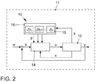
- FIG. 2 shows in a first embodiment, an exemplary representation of a control loop 10 with a controlled system 12.
- a controller 14 of the control loop 10 may be in a controller 11 or be executed.
- control unit 11 Furthermore, a gain scheduling and a feedforward control can be realized in the control unit 11.
- the control unit 11 may be provided, for example, for a motor vehicle, for example an engine control unit of a diesel engine provided as an internal combustion engine 100.
- the control unit 11 controls the controlled system 12, which includes, for example, a boost pressure control and a simultaneous high-pressure EGR control and, optionally, as explained, a low-pressure EGR control.
- boost control is exclusively linked to simultaneous low pressure EGR control. It becomes clear that the method can be variably used for all applications.
- the control unit 11 comprises, the preceding embodiments summarized the controller 14, to which the respective manipulated variables u (u1, u2, u3) are supplied, which act on the controlled system 12.
- State variables x (x1, x2, x3, x4, x5), which are measured or estimated, are also fed back to the controller 14, summarizing the previous embodiments, and act on the controlled system 12.
- Controlled variables y are output from the controlled system 12 and fed back in the control loop.
- the controlled variables y are subtracted from nominal values or reference variables w, which results in the control deviation e, which is supplied to the controller 14.
- a controller parameter generator 16 generates controller parameter p for the controller 14.
- variables of the controlled system 12 or scheduling variables s are supplied to the controller parameter generator 16.
- the controller parameter generator 16 comprises a plurality of Gaussian process models 18 for determining the controller parameters p as a function of the variables s of the controlled system 12.
- the controller 14 is designed as a multi-variable controller. Accordingly, a controller parameter p, a Gaussian process model 18 and a scheduling variable s are provided for each variable.
- the controller parameter generator 16 determines online, that is, during operation of the controlled system 12, in each computing step, the controller parameters p as a function of the supplied scheduling variables s, wherein the controller parameters P are the outputs of the Gaussian process models 18.
- FIG. 3 shows a further second embodiment of the control circuit 10 and the controller 11, respectively.
- the embodiment of FIG. 3 based on the in FIG. 2 illustrated control unit 11.
- control unit 11 an observer 20 for estimating the state variables x (x1, x2, x3, x4, x5) of the controlled system 12.
- the observer 20 contains a model 22 of the controlled system.
- the model 22 outputs on the one hand the state variables x (x1, x2, x3, x4, x5) to the controller 14 and on the other modeled measurands m '.
- a node such as an adder
- available measurands m of the controlled system 12 are subtracted from the modeled measurands m 'of the model 22.
- the result is a measurement error or error signal f which is fed to an estimation amplifier 24.
- the estimation amplifier 24 includes, as FIG. 3 illustrates, analogous to the controller parameter generator 16, a plurality of Gaussian process models 18 which generate amplification factors or manipulated variables u 'of the observer 20.
- the complete feedback of the state variables x (x1, x2, x3, x4, x5) of the controlled system 12 is realized by the observer 20.
- the gain factors that lead to the convergence of the estimation error via the generation of an additional setting component u 'in the observer structure of the observer 20 are modeled as Gaussian processor 18.
- FIG. 4 is a further third embodiment of the control circuit 10 and the control unit 11 is shown.
- one or more model portions of the controller 14 are implemented as a Gaussian process model 18.
- the described scheduling is then implemented as an element or functional part within the controller 14.
- the scheduling and the actual controller structure are merged with it.
- a model of the controller 14 channels of the controller can be considered, which correspond to one or more sizes of a multi-variable controller.
- 14 individual components within a channel can be regarded as model components of the controller.
- the probability values that are determined by the Gaussian process modeling 18 provide information about the quality of the determined parameter value, in particular the controller parameter p. Therefore, these probability values can be used directly within the controller structure in order to produce a more conservative (more attenuated) behavior of the controlled controlled system 12 with low modeling quality.
- the determined controller parameters p are varied as a function of the probability values in a separate functionality of the controller 14 in such a way that the attenuation of the nominally controlled system is increased.
Abstract
Die Erfindung betrifft ein Verfahren zur Ladedruckregelung eines Turboladers (200, 300) mit variabler Turbinengeometrie (VTG) oder zur Ladedruckregelung eines Turboladers (200, 300) mit variabler Turbinengeometrie (VTG) und gleichzeitiger Regelung mindestens einer Abgasrückführungsrate einer Abgasrückführung (Hochdruck-AGR, Niederdruck-AGR) einer Verbrennungskraftmaschine (100), dessen Reglerparameter (p) beim Regeln einer Regelstrecke (12) mit einem Regler (14) in Abhängigkeit von Größen (s) der Regelstrecke (12) variieren. Es ist vorgesehen, dass zur Bestimmung der Reglerparameter (p) in Abhängigkeit der Größen (s) der Regelstrecke (12) mindestens ein Gauss-Prozess-Modell (18) in einer dafür eingerichteten Vorrichtung (16) zur Bestimmung der Reglerparameter (p) verwendet wird, wobei die bestimmten Reglerparameter (p) die Ausgänge der Gauß-Prozess-Modelle (18) sind.The invention relates to a method for boost pressure control of a turbocharger (200, 300) with variable turbine geometry (VTG) or charge pressure control of a turbocharger (200, 300) with variable turbine geometry (VTG) and simultaneous control of at least one exhaust gas recirculation rate of exhaust gas recirculation (high pressure EGR, low pressure AGR) of an internal combustion engine (100) whose controller parameters (p) when controlling a controlled system (12) with a controller (14) vary as a function of variables (s) of the controlled system (12). It is provided that at least one Gaussian process model (18) is used to determine the controller parameters (p) as a function of the variables (s) of the controlled system (12) in a device (16) designed for determining the controller parameters (p) where the particular controller parameters (p) are the outputs of the Gaussian process models (18).
Description
Die Erfindung betrifft ein Verfahren zum Regeln einer Regelstrecke, eine Vorrichtung zur Erzeugung von Reglerparametern und ein Steuergerät. Die Erfindung betrifft insbesondere eine Regelung mit einem Gauß-Prozess-Modell zur Bestimmung der Reglerparameter.The invention relates to a method for regulating a controlled system, a device for generating controller parameters and a control device. In particular, the invention relates to a control with a Gaussian process model for determining the controller parameters.
Bei Mehrgrößenreglern sind lokal lineare Modelle nur in definierten Bereichen des Zustandsraums gültig. Für jedes der lokal linearen Modelle wird ein dort gültiger Regler entworfen, der über ein bestimmtes Parameterset verfügt. Die Werte der Reglerparameter für die entworfenen Regler sind bezüglich der Bereiche des Zustandsraums variant und müssen in Abhängigkeit von Größen der Regelstrecke variiert werden (Scheduling), um eine definierte Güte (Performance, Stabilität, Robustheit) des geschlossenes Regelkreises zu gewährleisten.For multivariable controllers, locally linear models are only valid in defined areas of the state space. For each of the local linear models, a valid controller is designed there, which has a certain set of parameters. The values of the controller parameters for the designed controllers are variant with respect to the regions of the state space and have to be varied (scheduling) in dependence on variables of the controlled system in order to ensure a defined quality (performance, stability, robustness) of the closed loop.
Das Scheduling von Reglerparametern (zum Beispiel bei PID-Reglern) erfolgt derzeit mittels Kennfeldmodellen in Abhängigkeit von (zumeist mehreren) Größen der betreffenden Regelstrecke (zum Beispiel Last und Drehzahl) oder in Abhängigkeit von Sollgrößen des betrachteten Regelkreises.The scheduling of controller parameters (for example in the case of PID controllers) currently takes place by means of characteristic map models as a function of (usually several) variables of the relevant controlled system (for example load and rotational speed) or depending on the setpoint variables of the considered control circuit.
Die Parametrierung der Kennfelder für Reglerparameter mit mehr als zwei Eingangsgrößen ist manuell nur mit großem Aufwand durchführbar. Zudem ergeben sich Probleme hinsichtlich der Glattheit des Kennfeldverlaufs. Ziel ist es, stetige und stetig differenzierbare Abhängigkeiten zu modellieren, um numerische Probleme zu verhindern.The parameterization of the maps for controller parameters with more than two input variables can be performed manually only with great effort. In addition, problems arise with regard to the smoothness of the characteristic curve course. The goal is to model continuous and continuously differentiable dependencies to prevent numerical problems.
Dies kann mit den derzeitigen Implementierungen nicht sichergestellt werden. Dies führt zu Einschränkungen in der Regelgüte. Nachteilig ist auch der derzeit hohe Speicherbedarf bedingt durch eine hohe Stützstellenanzahl.This can not be ensured with the current implementations. This leads to restrictions in the control quality. Another disadvantage is the currently high storage requirements due to a high number of support points.
Ferner werden die Druckschriften
Der Erfindung liegt nun die Aufgabe zugrunde, insbesondere mehrdimensionale Reglerparameter einfach und mit verbesserter Güte zu erzeugen.The invention is based on the object, in particular to produce multi-dimensional controller parameters easily and with improved quality.
Die Erfindung weist unabhängig von einem bestimmten Anwendungsfall folgende Merkmale auf:The invention has the following features independently of a particular application:
Die erfindungsgemäße Vorrichtung ist eingerichtet zur Erzeugung von Reglerparametern für einen Regler, dessen Reglerparameter in Abhängigkeit von Größen einer Regelstrecke variieren. Erfindungsgemäß ist erfindungsgemäß vorgesehen, dass die Vorrichtung mindestens ein Gauß-Prozess-Modell eingerichtet zur Bestimmung der Reglerparameter in Abhängigkeit der Größen der Regelstrecke aufweist.The device according to the invention is set up for generating controller parameters for a controller whose controller parameters vary as a function of the variables of a controlled system. According to the invention, it is provided that the device has at least one Gaussian process model set up for determining the controller parameters as a function of the variables of the controlled system.
Das oder die Gauß-Prozess-Modelle sind Modelle von Reglerparametern und werden verwendet, um Reglerparameter (beziehungsweise Parameter eines Beobachters) in Abhängigkeit von beliebigen, unter anderem aber nicht ausschließlich physikalischen Größen zu beschreiben beziehungsweise zu generieren.The Gaussian process model or models are models of controller parameters and are used to describe or generate controller parameters (or parameters of an observer) as a function of any, inter alia, but not exclusively physical variables.
Ein Gaußprozess ist in der Wahrscheinlichkeitstheorie ein stochastischer Prozess, bei dem jede endliche Teilmenge von Zufallsvariablen mehrdimensional normalverteilt (gaußverteilt) ist. Während die mehrdimensionale Gaußverteilung eine Gaußverteilung von Vektoren darstellt, beschreibt ein Gaußprozess die Gaußverteilung eines Kontinuums von Zufallsvariablen und insbesondere eine Gaußverteilung von Funktionen.A Gaussian process is a stochastic process in probability theory in which every finite subset of random variables is multidimensionally normalized (Gaussian distributed). While the multidimensional Gaussian distribution represents a Gaussian distribution of vectors, a Gaussian process describes the Gaussian distribution of a continuum of random variables, and in particular a Gaussian distribution of functions.
Gauß-Prozess-Modelle sind inhärent stetig und stetig differenzierbar, sodass sich glatte Kennfeldverläufe der Regler- beziehungsweise Beobachterparameter ergeben. Die Modellierung von mehrdimensionalen Zusammenhängen ist inhärent möglich und unproblematisch. Mittels Gauß-Prozessen lässt sich der benötigte Speicherplatz im Vergleich zu kennfeldbasierten Lösungen reduzieren. Verbunden mit einem inhärent glatten Interpolationsverhalten, sowie einem physikalisch sinnvollen Extrapolationsverhalten ermöglichen Gauß-Prozess-Modelle eine deutliche Verbesserung der Adaption der Regelung oder des verwendeten Zustandsschätzers hinsichtlich numerischer Stabilität, Rechenzeit, Speicheraufwand. Der Applikationsaufwand beziehungsweise der Aufwand zur manuellen Parametrierung wird deutlich reduziert.Gaussian process models are inherently continuous and continuously differentiable, resulting in smooth characteristic curves of the controller or observer parameters. The modeling of multi-dimensional contexts is inherently possible and unproblematic. By means of Gaussian processes, the required storage space can be reduced in comparison to map-based solutions. Combined with an inherently smooth interpolation behavior and a physically sensible extrapolation behavior, Gaussian process models make it possible to significantly improve the adaptation of the control or of the state estimator used with regard to numerical stability, computing time and memory requirements. The application effort or the effort for manual parameterization is significantly reduced.
Ein Gauß-Prozess-Modell kann für einen Reglerparameter des Reglers vorgesehen sein. Somit kann für jede Größe eines Mehrgrößenreglers ein Gauß-Prozess-Modell zur Erzeugung eines Reglerparameters beziehungsweise eines Werts eines Reglerparametervektors vorgesehen sein.A Gaussian process model may be provided for a controller parameter of the controller. Thus, a Gaussian process model for generating a controller parameter or a value of a controller parameter vector can be provided for each variable of a multivariable controller.
Das erfindungsgemäße Steuergerät eingerichtet zum Einsatz in einem Fahrzeug, welches einen Regler, dessen Reglerparameter in Abhängigkeit von Größen einer Regelstrecke variieren, und eine Vorrichtung eingerichtet zur Erzeugung von Reglerparametern für den Regler umfasst, beinhaltet, dass das Steuergerät mindestens ein Gauß-Prozess-Modell eingerichtet zur Bestimmung der Reglerparameter in Abhängigkeit der Größen der Regelstrecke aufweist. Es gelten die gleichen Vorteile und Modifikationen wie zuvor beschrieben. Die Erzeugung von Reglerparametern mittels eines Gauß-Prozess-Modells ist insbesondere für komplexe und zeitkritische Regelungsprozesse in Fahrzeugen wie zum Beispiel die Motorsteuerung oder Abgasregelung prädestiniert.The control unit according to the invention configured for use in a vehicle, which comprises a controller whose controller parameters vary as a function of variables of a controlled system, and a device for generating controller parameters for the controller, comprises that the controller sets up at least one Gaussian process model for determining the controller parameters as a function of the variables of the controlled system. The same advantages and modifications apply as described above. The generation of controller parameters by means of a Gaussian process model is predestined in particular for complex and time-critical control processes in vehicles such as, for example, engine control or exhaust gas control.
Ein Beobachter kann zur Schätzung von Zustandsgrößen der Regelstrecke vorgesehen sein, und die geschätzten Zustandsgrößen können zu dem Regler zurückgeführt werden, wobei der Beobachter mindestens ein Gauß-Prozess-Modell eingerichtet zur Modellierung von Verstärkungsfaktoren aufweist. Bei dem oder den Gauß-Prozess-Modellen des Beobachters kommen andere Gauß-Prozess-Modelle als bei der Regelung zum Einsatz, da anstelle der Reglerparameter die Verstärkung ermittelt wird, die zur Zustandsschätzung verwendet wird. Die Gauß-Prozess-Modelle von Beobachter und Regler können mit der gleichen Methodik erstellt werden, da zumindest für lineare Systeme eine äquivalente Zustandsraumdarstellung des Beobachters möglich ist. Auch bei der Rückführung der Zustandsgrößen kann vorteilhaft auf ein oder mehrere Gauß-Prozess-Modelle zurückgegriffen werden.An observer may be provided for estimating state variables of the controlled system, and the estimated state variables may be fed back to the controller, wherein the observer has at least one Gaussian process model configured to model gain factors. In the Gaussian process model (s) of the observer, other Gaussian process models are used than in the control, because instead of the controller parameters, the gain used for state estimation is determined. The Gaussian process models of observer and controller can be created with the same methodology, since at least for linear systems an equivalent state space representation of the observer is possible. Also in the feedback of the state variables can be used advantageously on one or more Gaussian process models.
Ein Modellanteil des Reglers kann als Gauß-Prozess-Modell ausgebildet sein. Hier wird das Scheduling, das heißt die Bestimmung oder Variation der Reglerparameter in Abhängigkeit von Größen der Regelstrecke, und die eigentliche Reglerstruktur in einer Einheit kombiniert. Dies kann positive Synergieeffekte haben.A model portion of the controller may be designed as a Gaussian process model. Here, the scheduling, ie the determination or variation of the controller parameters as a function of variables of the controlled system, and the actual controller structure are combined in one unit. This can have positive synergy effects.
Das Steuergerät kann eine Logikschaltung aufweisen, welche eingerichtet ist, zumindest einen Teil eines Gauß-Prozess-Modells auszuführen. So können Gauß-Prozess-Modelle online, das heißt während des Betriebs, in Hardware berechnet werden, was den Prozessorkern entlastet und die Zykluszeiten reduziert.The controller may include a logic circuit configured to execute at least a portion of a Gaussian process model. Thus, Gaussian process models can be calculated online, that is during operation, in hardware, which relieves the processor core and reduces cycle times.
Das erfindungsgemäße Verfahren zum Regeln einer Regelstrecke mit einem Regler, dessen Reglerparameter in Abhängigkeit von Größen einer Regelstrecke variieren, ist dadurch gekennzeichnet, dass zur Bestimmung der Reglerparameter in Abhängigkeit der Größen der Regelstrecke mindestens ein Gauß-Prozess-Modell verwendet wird. Es gelten die gleichen Vorteile und Modifikationen wie zuvor beschrieben.The inventive method for controlling a controlled system with a controller whose controller parameters vary depending on variables of a controlled system is characterized in that at least one Gaussian process model is used to determine the controller parameters as a function of the variables of the controlled system. The same advantages and modifications apply as described above.
Mittels mehrerer Gauß-Prozess-Modelle können mehrdimensionale Zusammenhänge der Regelstrecke modelliert werden. Dies ermöglicht eine parallele Verarbeitung mehrdimensionaler Parameter.By means of several Gaussian process models, multi-dimensional relationships of the controlled system can be modeled. This allows parallel processing of multi-dimensional parameters.
Mindestens ein Gauß-Prozess-Modell wird vor einem Betrieb rechnergestützt mit Daten versehen. Die Bedatung der Modelle erfolgt offline mittels Computer-Tools, sodass eine manuelle Bedatung nicht notwendig ist.At least one Gaussian process model is computer-aided prior to operation. The models are modeled offline using computer tools, so manual data entry is not necessary.
Die Regelstrecke kann eine Ladedruckreglung oder eine Ladedruckregelung und eine Abgasrückführung eines Verbrennungsmotors (Verbrennungskraftmaschine) eines Fahrzeugs umfassen.The controlled system may include a boost pressure regulation or a boost pressure control and an exhaust gas recirculation of an internal combustion engine (internal combustion engine) of a vehicle.
Diese mehrdimensionale Anwendung miteinander gekoppelter Bestandteile, wie zum Beispiel der Ladedruckregelung oder der Ladedruckregelung und einer Abgasrückführungsregelung, sind sehr zuverlässig mit dem Steuergerät zu regeln.These multi-dimensional application of coupled components, such as the boost pressure control or boost pressure control and exhaust gas recirculation control, are very reliable to control with the control unit.
Die Erfindung weist bezogen auf einen bestimmten Anwendungsfall, insbesondere der bereits genannte Ladedruckregelung eines Turboladers mit variabler Turbinengeometrie (erste Ausführungsvariante) oder die ebenfalls bereits genannte Ladedruckregelung des Turboladers mit variabler Turbinengeometrie und mindestens einer Abgasrückführungsregelung (zweite Ausführungsvariante) einer Abgasrückführung (Hochdruck-Abgasrückführung und/oder Niederdruck-AGR) folgende Merkmale auf:The invention relates to a specific application, in particular the already mentioned boost pressure control of a turbocharger with variable turbine geometry (first embodiment) or the likewise already mentioned boost pressure control of the turbocharger with variable turbine geometry and at least one exhaust gas recirculation control (second embodiment variant) exhaust gas recirculation (high-pressure exhaust gas recirculation and / or low pressure EGR) have the following characteristics:
Ausgangspunkt der Erfindung ist ein Verfahren zur Ladedruckregelung eines Turboladers mit variabler Turbinengeometrie einer Verbrennungskraftmaschine, dessen Reglerparameter beim Regeln einer Regelstrecke mit einem Regler in Abhängigkeit von Größen der Regelstrecke variieren.The starting point of the invention is a method for boost pressure control of a turbocharger with variable turbine geometry of an internal combustion engine, the controller parameters of which vary when controlling a controlled system with a controller as a function of variables of the controlled system.
Erfindungsgemäß ist vorgesehen, dass zur Bestimmung der Reglerparameter in Abhängigkeit der Größen der Regelstrecke mindestens ein Gauss-Prozess-Modell in einer dafür eingerichteten Vorrichtung zur Bestimmung der Reglerparameter verwendet wird, wobei die bestimmten Reglerparameter die Ausgänge der Gauß-Prozess-Modelle sind.According to the invention, at least one Gaussian process model is used in a device designed to determine the controller parameters for determining the controller parameters as a function of the variables of the controlled system, the specific controller parameters being the outputs of the Gaussian process models.
Bevorzugt ist vorgesehen, dass die Ladedruckregelung des Turboladers mit variabler Turbinengeometrie (erste Ausführungsvariante) gleichzeitig mit der Regelung mindestens einer Abgasrückführungsrate (zweite Ausführungsvariante) einer Abgasrückführung (Hochdruck-Abgasrückführung und/oder Niederdruck-AGR) der Verbrennungskraftmaschine vorgenommen wird, deren Reglerparameter beim Regeln der Regelstrecke mit dem Regler in Abhängigkeit von Größen der Regelstrecke variieren.It is preferably provided that the boost pressure control of the turbocharger with variable turbine geometry (first embodiment) simultaneously with the control of at least one exhaust gas recirculation rate (second embodiment) of exhaust gas recirculation (high pressure exhaust gas recirculation and / or low pressure EGR) of the internal combustion engine is performed, the controller parameters in the regulation of Controlled system with the controller vary depending on the size of the controlled system.
Bei der Ladedruckregelung des Turboladers mit variabler Turbinengeometrie (erste Ausführungsvariante) oder bei Ladedruckregelung des Turboladers mit variabler Turbinengeometrie und gleichzeitiger Regelung mindestens einer Abgasrückführungsrate (zweite Ausführungsvariante) einer Abgasrückführung (Hochdruck-Abgasrückführung und/oder Niederdruck-AGR) ist in bevorzugter Ausgestaltung der Erfindung vorgesehen, dass in Abhängigkeit von auf die Regelstrecke wirkenden Stellgrößen mittels eines Beobachters in die Regelstrecke einfließende Zustandsgrößen geschätzt oder gemessen werden, die zu dem Regler zurückgeführt werden, wobei der Beobachter über mindestens ein Gauss-Prozess-Modell Verstärkungsfaktoren modelliert.In the boost pressure control of the turbocharger with variable turbine geometry (first embodiment) or at boost pressure control of the turbocharger with variable turbine geometry and simultaneous control of at least one exhaust gas recirculation rate (second embodiment) of exhaust gas recirculation (high pressure exhaust gas recirculation and / or low pressure EGR) is provided in a preferred embodiment of the invention in that, as a function of manipulated variables acting on the controlled system, an amount of state variables flowing into the controlled system is estimated or measured by an observer and fed back to the controller, wherein the observer models gain factors via at least one Gaussian process model.
In beiden Ausführungsvarianten ist bevorzugt vorgesehen, dass in Abhängigkeit von auf die Regelstrecke wirkenden Stellgrößen mittels des Beobachters in die Regelstrecke einfließende Zustandsgrößen geschätzt oder gemessen werden, die zu dem Regler zurückgeführt werden, wobei der Beobachter über mindesten ein Gauss-Prozess-Modell Verstärkungsfaktoren modelliert.In both embodiments, it is preferably provided that depending on manipulated variables acting on the controlled system by means of the observer into the controlled system inflowing state variables are estimated or measured, which are fed back to the controller, wherein the observer models at least one Gaussian process model gain factors.
Gemäß der ersten Ausführungsvariante ist vorgesehen, dass zur Ladedruckregelung des Turboladers als Zustandsgröße/n, die dem Regler zugeführt wird/werden und die auf die Regelstrecke wirkt/wirken, ein Druck vor dem Turbolader, eine Turboladerdrehzahl des Turboladers, ein Druck nach dem Turbolader, ein Druck vor der Turbine mit variabler Turbinengeometrie,
ein Druck nach der Turbine mit variabler Turbinengeometrie verwendet wird/werden.According to the first embodiment, it is provided that for boost pressure control of the turbocharger as state variable / n, which is / are the controller and / which act on the controlled system, a pressure in front of the turbocharger, a turbocharger speed of the turbocharger, a pressure after the turbocharger, a pressure in front of the turbine with variable turbine geometry,
a pressure is used after the turbine with variable turbine geometry.
Gemäß der zweiten Ausführungsvariante ist bevorzugt vorgesehen, dass zur Ladedruckregelung des Turboladers und zur Regelung der Abgasrückführungsrate als Zustandsgröße/n, die dem Regler zugeführt wird/werden und die auf die Regelstrecke wirkt/wirken, ein Druck vor dem Turbolader zur Ladedruckregelung und zur Niederdruck-AGR-Regelung, zur Ladedruckregelung eine Turboladerdrehzahl des Turboladers, zur Ladedruckregelung und Hochdruck-Abgasrückführungs-Regelung ein Druck nach dem Turbolader, zur Ladedruckregelung und Hochdruck-Abgasrückführungs-Regelung ein Druck vor der Turbine mit variabler Turbinengeometrie, zur Ladedruckregelung und zur Niederdruck-AGR-Regelung ein Druck nach der Turbine mit variabler Turbinengeometrie verwendet wird/werden.According to the second embodiment, it is preferably provided that for boost pressure control of the turbocharger and for controlling the exhaust gas recirculation rate as state variable / n, which is / are the controller and / or act on the controlled system, a pressure in front of the turbocharger for boost pressure control and low pressure EGR control, turbocharger turbo supercharger speed for boost pressure control, boost pressure control and high pressure exhaust gas recirculation control, turbocharger pressure, boost pressure control and high pressure exhaust gas recirculation control pressure upstream of variable turbine geometry turbine for boost pressure control and low pressure EGR control. Control a pressure after the turbine is used with variable turbine geometry.
Gemäß der der ersten und der zweiten Ausführungsvariante ist bevorzugt vorgesehen, dass zur Ladedruckregelung des Turboladers als Stellgröße, die dem Regler zurückgeführt wird und die auf die Regelstrecke wirkt, eine Verstellposition der Turbine mit variabler Turbinengeometrie verwendet wird.According to the first and the second embodiment variant, it is preferably provided that an adjusting position of the turbine with variable turbine geometry is used for boost pressure control of the turbocharger as a manipulated variable, which is returned to the controller and which acts on the controlled system.
Bevorzugt ist gemäß der zweiten Ausführungsvariante vorgesehen, dass zur Regelung der Abgasrückführungsrate als Stellgröße/n, die dem Regler zurückgeführt wird/werden und die auf die Regelstrecke wirkt/wirken, je nachdem welche/s Abgasrückführungssystem/e allein oder in Kombination zum Einsatz kommt/kommen, eine Ventilposition eines Ventils in einer Abgas-Rückführungsleitung der Hochdruck-Abgasrückführung (Hochdruck-AGR), eine Ventilposition eines Ventils in der Abgas-Rückführungsleitung der Niederdruck Abgasrückführung (Niederdruck-AGR) verwendet wird/werden.Preferably, according to the second embodiment variant, provision is made for regulating the exhaust gas recirculation rate as manipulated variable (s) which is fed back to the controller and which acts on the controlled system, depending on which exhaust gas recirculation system is used alone or in combination. a valve position of a valve in a high pressure exhaust gas recirculation (EGR) exhaust gas recirculation line, a valve position of a valve in the low pressure exhaust gas recirculation (EGR) exhaust gas recirculation line is used.
Für beide Ausführungsvarianten gilt bevorzugt, dass Regelgrößen aus der Regelstrecke ausgegeben und im Regelkreis zurückgeführt werden, wobei die Regelgrößen von Sollgrößen oder Führungsgrößen subtrahiert werden, wodurch sich eine Regelabweichung ergibt, welche dem Regler zugeführt wird.For both variants, it is preferred that controlled variables are output from the controlled system and fed back in the control loop, wherein the controlled variables are subtracted from desired variables or reference variables, resulting in a control deviation which is supplied to the controller.
Ferner gilt bevorzugt für beide Ausführungsvarianten, dass die Vorrichtung Reglerparameter für den Regler bestimmt, indem der Vorrichtung aus der Regelstrecke Regelgrößen zugeführt werden, wobei mindestens eine der Größen der Regelstrecke der Vorrichtung als Scheduling-Größe zugeführt wird.Furthermore, it is preferably for both embodiments that the device determines controller parameters for the controller by the control device controlled variables are supplied to the device, wherein at least one of the variables of the controlled system is supplied to the device as a scheduling size.
Dabei ist bevorzugt vorgesehen, dass die Vorrichtung mehrere Gauss-Prozess-Modelle zur Bestimmung der Reglerparameter in Abhängigkeit der mindestens einen Scheduling-Größe der Regelstrecke umfasst, so dass mittels der mehreren Gauss-Prozess-Modelle mehrdimensionale Zusammenhänge der Regelstrecke modelliert werden können.It is preferably provided that the device several Gaussian process models for determining the controller parameters as a function of at least one scheduling size of Controlled system includes, so that by means of several Gaussian process models multi-dimensional relationships of the controlled system can be modeled.
Außerdem ist bevorzugt vorgesehen, dass die Vorrichtung während des Betriebs der Regelstrecke, in jedem Rechenschritt die Reglerparameter in Abhängigkeit von der mindestens einen zugeführten Scheduling-Größe online bestimmt.In addition, it is preferably provided that during operation of the controlled system, the device determines the controller parameters online in each computing step as a function of the at least one supplied scheduling variable.
Bezüglich des Beobachters ist bevorzugt vorgesehen, dass der Beobachter zur Schätzung der Zustandsgrößen der Regelstrecke ein Modell enthält, welches die Zustandsgrößen und modellierte Messgrößen an den Regler ausgibt, wobei verfügbare Messgrößen der Regelstrecke von den modellierten Messgrößen des Modells subtrahiert werden, wonach im Ergebnis einem Schätzverstärker ein Messfehler oder ein Fehlersignal zugeführt wird.With regard to the observer, it is preferably provided that the observer for estimating the state variables of the controlled system contains a model which outputs the state variables and modeled measured variables to the controller, whereby available measured variables of the controlled system are subtracted from the modeled measured variables of the model, which in turn results in an estimation amplifier a measurement error or an error signal is supplied.
Der Schätzverstärker weist analog zu der Vorrichtung mehrere Gauss-Prozess-Modelle auf, welche Verstärkungsfaktoren beziehungsweise Stellgrößen des Beobachters erzeugen, so dass eine vollständige Rückführung der Zustandsgrößen der Regelstrecke durch den Beobachter durchgeführt wird, wozu die Verstärkungsfaktoren, die zur Konvergenz des Schätzfehlers über die Generierung eines zusätzlichen Stellanteils in der Struktur des Beobachters führen, wiederum als Gauss-Prozessor modelliert werden.The estimation amplifier has, analogously to the device, several Gaussian process models which generate gain factors or manipulated variables of the observer, so that complete feedback of the state variables of the controlled system is carried out by the observer, for which purpose the amplification factors used for the convergence of the estimation error over the generation An additional Stellanteils in the structure of the observer, in turn, be modeled as a Gaussian processor.
Das Verfahren zeichnet sich bei beiden Ausführungsvarianten dadurch aus, dass mindestens ein Modellanteil oder mehrere Modellanteile des Reglers als Gauss-Prozess-Modell ausgeführt ist/sind, wobei das Scheduling als Element oder Funktionsanteil innerhalb des Reglers realisiert werden, so dass das Scheduling und die Reglerstruktur zusammengeführt sind, wobei der mindestens eine Modellanteil oder die mehreren Modellanteile des Reglers Kanäle des Reglers sind, die zu einer oder mehreren Größe/n eines Mehrgrößenreglers korrespondieren, wobei die Modellanteile des Reglers als Bestandteile innerhalb eines Kanals fungieren.In both variants of the method, the method is characterized in that at least one model component or several model components of the controller is / are implemented as a Gaussian process model, the scheduling being implemented as an element or functional component within the controller, such that the scheduling and the controller structure wherein the at least one or more model portions of the controller are channels of the controller corresponding to one or more sizes of a multivariable controller, the model portions of the controller acting as components within a channel.
Über Modellierung der Gauss-Prozess-Modelle werden bei beiden Ausführungsvarianten bevorzugt Wahrscheinlichkeitswerte ermittelt, die in besonders vorteilhafter Weise des Verfahrens eine Aussage über Güte der ermittelten Reglerparameter liefern, wobei diese Wahrscheinlichkeitswerte innerhalb der Reglerstruktur direkt verwendet werden, um bei einer geringen Modellierungsgüte ein konservativeres, insbesondere stärker gedämpftes Verhalten der geregelten Regelstrecke zu erzeugen, wozu die ermittelten Reglerparameter in Abhängigkeit der Wahrscheinlichkeitswerte in einer eigenen Funktionalität des Reglers variiert werden, so dass die Dämpfung des nominellen geregelten Systems erhöht wird.By modeling the Gaussian process models, in both embodiments, preferably, probability values are determined which in a particularly advantageous manner provide information about the quality of the determined controller parameters, wherein these probability values are used directly within the controller structure in order to obtain a more conservative, In particular, to generate more attenuated behavior of the controlled controlled system, for which purpose the determined controller parameters are varied as a function of the probability values in a separate functionality of the controller, so that the attenuation of the nominally controlled system is increased.
Die Erfindung betrifft ein Steuergerät, eingerichtet zum Einsatz in einem Fahrzeug, insbesondere ein Motorsteuergerät, welches einen Regler, dessen Reglerparameter in Abhängigkeit von Größen einer Regelstrecke variieren, und eine Vorrichtung eingerichtet zur Erzeugung von Reglerparametern für den Regler umfasst, wobei erfindungsgemäß vorgesehen ist, dass das Steuergerät als Vorrichtung einen die Reglerparameter für den Regler bestimmenden Reglerparameter-Generator umfasst, wobei der Reglerparameter-Generator mindestens ein Gauss-Prozess-Modell aufweist, wobei der Reglerparameter-Generator zur Bestimmung der Reglerparameter in Abhängigkeit mindestens einer Größe der Regelstrecke eingerichtet ist, wobei die bestimmten Reglerparameter die Ausgänge der Gauß-Prozess-Modelle sind.The invention relates to a control device, designed for use in a vehicle, in particular an engine control unit, which comprises a controller whose controller parameters vary depending on variables of a controlled system, and a device for generating controller parameters for the controller, wherein it is provided according to the invention the controller comprises as device a controller parameter generator determining the controller parameters for the controller, the controller parameter generator having at least one Gaussian process model, the controller parameter generator being configured to determine the controller parameters as a function of at least one variable of the controlled system, wherein the specific controller parameters are the outputs of the Gaussian process models.
Das Steuergerät ist bevorzugt dadurch gekennzeichnet, dass ein Beobachter zur Schätzung von Zustandsgrößen der Regelstrecke vorgesehen ist, und dass die geschätzten Zustandsgrößen dem Regler zugeführt werden, wobei der Beobachter mindestens ein Gauss-Prozess-Modell aufweist, welches zur Modellierung von Verstärkungsfaktoren eingerichtet ist. Im Steuergerät ist mindestens ein Modellanteil des Reglers als Gauss-Prozess-Modell ausgebildet.The control unit is preferably characterized in that an observer is provided for estimating state variables of the controlled system, and that the estimated state variables are supplied to the controller, wherein the observer has at least one Gaussian process model which is set up for modeling amplification factors. In the control unit at least one model portion of the controller is designed as a Gaussian process model.
Das Steuergerät umfasst die Regelstrecke einer Ladedruckregelung eines Turboladers mit variabler Turbinengeometrie gemäß der ersten Ausführungsvariante oder eine Ladedruckregelung eines Turboladers mit variabler Turbinengeometrie und gleichzeitiger Regelung einer Abgasrückführungsrate mindestens einer Abgasrückführung (Hochdruck-Abgasrückführung und/oder Niederdruck-Abgasrückführung) der Verbrennungskraftmaschine gemäß der zweiten Ausführungsvariante.The control unit comprises the controlled system of a boost pressure control of a turbocharger with variable turbine geometry according to the first embodiment or a boost pressure control of a turbocharger with variable turbine geometry and simultaneous control of an exhaust gas recirculation rate at least one exhaust gas recirculation (high pressure exhaust gas recirculation and / or low pressure exhaust gas recirculation) of the internal combustion engine according to the second embodiment.
Die Erfindung wird nachfolgend anhand der zugehörigen Zeichnungen erläutert. Es zeigen:
Figur 1- ein Anwendungsbeispiel eines Verfahrens zur Ladedruckregelung eines Turboladers mit variabler Turbinengeometrie und gleichzeitiger Regelung einer Abgasrückführungsrate einer Abgasrückführung einer Verbrennungskraftmaschine gemäß der zweiten Ausführungsvariante;
- Figur 2
- ein erstes Ausführungsbeispiel eines Regelkreises;
- Figur 3
- ein zweites Ausführungsbeispiel eines Regelkreises;
- Figur 4
- ein drittes Ausführungsbeispiel eines Regelkreises.
- FIG. 1
- an application example of a method for boost pressure control of a turbocharger with variable turbine geometry and simultaneous control of an exhaust gas recirculation rate exhaust gas recirculation of an internal combustion engine according to the second embodiment;
- FIG. 2
- a first embodiment of a control loop;
- FIG. 3
- a second embodiment of a control loop;
- FIG. 4
- a third embodiment of a control loop.
Im Folgenden wird zunächst ein für verschiedene Anwendungen einsetzbares Verfahren zur Auswahl von Scheduling Variablen und zum Design von Kennfeldern einer Reglerrückführmatrix beschrieben, was als Grundlage der Erfindung angesehen werden kann.In the following, a method for the selection of scheduling variables and for the design of characteristics of a regulator feedback matrix, which can be used for various applications, will first be described, which can be regarded as the basis of the invention.
Es werden die folgenden Annahmen getroffen. Gegeben sei das dynamische System x = ![]()
![]()
Bekannt sind zum Beispiel aus Messungen die Ruhelagen xAP , wobei AP einen Arbeitspunkt kennzeichnet. Dem zugeordnet ist ein Stellvektor im Arbeitspunkt uAP. Es wird des Weiteren angenommen, dass das System steuerbar ist und durch eine Zustandsrückführung u = fr (x), die den Stellvektor als Funktion des Zustandsvektors beschreibt, geregelt werden kann.Measurements are, for example, from measurements, the rest positions x AP , AP denotes an operating point. Associated with this is an actuating vector at the operating point u AP . It is further assumed that the system is controllable and can be controlled by a state feedback u = f r ( x ) describing the servo vector as a function of the state vector.
Dann kann u als Erweiterung des Zustandsvektors aufgefasst werden. Es ergibt sich das erweiterte System durch zeitliche Ableitung von u(x) zu: ![]()

![]()
Es kann festgestellt werden, dass der Gradient der Funktion u = fr (x) mitbestimmend ist für die Systemdynamik des geregelten Systems.It can be stated that the gradient of the function u = f r ( x ) determines the system dynamics of the controlled system.
Eine Linearisierung in einem Arbeitspunkt AP ergibt dann: 
Ziel ist es, eine geeignete Funktion u = fr (x) zu finden. Hier wird dafür das System in seinen Arbeitspunkten betrachtet. Für jeden Arbeitspunkt wird ein lokal linear gültiges Reglergesetz (welches die Abweichungen vom Arbeitspunkt berücksichtigt) mittels LQR-Verfahren bestimmt, das dann in ein kontinuierlich gültiges (im Sinne von u = fr (x)) überführt wird.The goal is to find a suitable function u = f r ( x ). Here, the system is considered in its working points. For each operating point, a locally valid linear regulator law (which takes into account the deviations from the operating point) is determined by means of the LQR method, which is then converted into a continuously valid (in the sense of u = f r ( x )).
Als Anforderungen für diese Überführung gelten, dass die lokal spezifizierte Dynamik durch die Überführung nicht verändert werden soll (lokale Stabilitäts- und Dämpfungserhaltung) und dass das globale Verhalten des nichtlinearen Systems aus Gleichung (0), das durch u = fr (x) erzeugt wird, ebenfalls dem spezifizierten Gütemaß genügen soll. Hierdurch soll das bezüglich des Gütemaßes optimale Verhalten und gleichzeitig die Stabilität und Dämpfung bei Übergängen zwischen Arbeitspunkten sichergestellt werden (globale Optimalitätserhaltung).The requirements for this transformation are that the locally specified dynamics should not be changed by the transfer (local stability and damping conservation) and that the global behavior of the nonlinear system is given by equation (0), which is given by u = f r ( x ) will also meet the specified quality standard. This is to ensure the optimal behavior with regard to the quality measure and at the same time the stability and damping of transitions between operating points (global optimality maintenance).
Zunächst wird ein Verfahren zur Linearisierung und Ermittlung lokal linearer Regler beschrieben. Es wird für jeden AP des Systems aus Gleichung (0) ein lokal lineares Modell erzeugt, das die Dynamik der Abweichungen vom Arbeitspunkt Δx = xAP - x charakterisiert. ![]()
![]()
Das Reglergesetz lautet ![]()
![]()
Das Verhalten des geregelten Systems im Arbeitspunkt ist dann ![]()
![]()
Die Regelung und das lokal lineare Modell haben nur eine Gültigkeit in einem gewissen Einzugsbereich des Zustandsraums um den Arbeitspunkt.The control and the locally linear model have only one validity in a certain catchment area of the state space around the operating point.
Nun wird die Kombination mit einer Vorsteuerung und Interpolation beschrieben.Now the combination with a precontrol and interpolation will be described.
Zur Vorsteuerung wird das Folgende festgestellt. Um das System in einem Arbeitspunkt betreiben zu können, ist ein Stellanteil notwendig, der es im Arbeitspunkt hält, sofern die Abweichung Δx vom AP zu null wird, da dann der korrigierende Stellanteil Δu ebenfalls zu null wird. Daher ist es sinnvoll, letzteren Stellanteil mit einem eigenen, den Arbeitspunkt charakterisierenden Stellanteil zu addieren. Dieser wird Vorsteuerung uAP genannt. Dieser Stellanteil sei wiederum abhängig vom Zustandsvektor: Je nachdem, wo im Zustandsraum sich das System befindet, werden ein geeigneter Arbeitspunkt xAP = fAP (x) und eine damit verbundene geeignete Vorsteuerung uAP (xAP ) gewählt, wobei fAP (x) eine Arbeitspunktauswahl beschreibt, welche eine Abbildung vom Ist-Zustand auf die Menge der Arbeitspunkte darstellt. Die Stellgröße ist dann: ![]()
![]()
Zur Interpolation wird das Folgende festgestellt. Jede Reglermatrix R̃AP ist ausschließlich in einem Einzugsgebiet um eine Ruhelage (Arbeitspunkt) AP gültig. Abhängig vom Ist-Zustand x des Systems, ist nun eine geeignete Reglermatrix R̃(x) definiert, die eng mit R̃AP assoziiert ist. Hierdurch wird das Reglergesetz zu ![]()
![]()
Die Funktionen R̃(x) = (r̃ij (x)) - mit (i, j) als Position des Matrixelements - können nun als Gauss-Prozess modelliert werden, sodass die Funktion hinreichend oft differenzierbar ist.The functions R ( x ) = ( r ij ( x )) - with (i, j) as the position of the matrix element - can now be modeled as a Gaussian process, so that the function is sufficiently differentiable.
Lokale Stabilitäts- und Dämpfungserhaltung: Damit lokal um die betrachteten Arbeitspunkte die durch Gleichung (2) spezifizierte Dynamik mittels des Reglergesetzes aus Gleichung (3) erhalten bleibt, ist es notwendig, die lokale Identität der Dynamikmatrizen aus Gleichungen (1) und (3) bezüglich der Dynamik in x herbeizuführen. Das bedeutet: ![]()
![]()
Linearisiert man u = fr (x) unter der Voraussetzung kleiner Änderungen um den Arbeitspunkt, ergibt sich die Änderung der Stellgröße im AP unter Berücksichtigung des dann anzuwendenden Reglergesetzes aus Gleichung (3) zu: ![]()
![]()
Sofern fAP (x) eine diskrete Funktion ist, erscheint als partielles Differenzial nach x dessen Delta-Impuls als Distribution in Gleichung (5).If f AP ( x ) is a discrete function, the partial differential to x appears as its delta pulse as a distribution in equation (5).
Dann gilt wegen der Äquivalenz in Gleichung (4) 
![]()
![]()
Gleichung 6 definiert die lokale Stabilitäts- und Dämpfungserhaltung.Equation 6 defines the local stability and attenuation conservation.
Dies lässt sich als Steigungsbedingung für die Funktionen in R̃(x) interpretieren. Die Gestalt der Vorsteuerung bestimmt daher zur lokalen Stabilitäts- und Dämpfungserhaltung maßgeblich die Form der Matrixfunktion R̃(x).This can be interpreted as a slope condition for the functions in R ( x ). The shape of the feedforward therefore determines the shape of the matrix function R ( x ) for the local stability and attenuation conservation.
Globale Optimalitätserhaltung: Unter der Annahme eines existierenden Reglergesetzes aus Gleichung (3) kann angegeben werden, inwiefern dieses global dem Gütekriterium J = ½ΔuTRΔu+½Δx TQΔx → min genügt. Hierzu wird klassischerweise die Hamilton-Funktion des nicht geregelten Systems aus Gleichung (0) betrachtet: ![]()
![]()
Hierbei stellt ψ T den Vektor der Lagrange-Multiplikatoren dar, die zusammen mit dem Zustandsvektor x das sogenannte adjungierte System bilden.Here, ψ T represents the vector of the Lagrangian multipliers, which together with the state vector x form the so-called adjoint system.
Für die optimale Steuerung bleibt die Hamilton-Funktion konstant: 
Hieraus folgt für die optimale Steuerung: (6) ![]()
![]()
Der Verlauf der Lagrange-Multiplikatoren ergibt sich aus der Bedingung: ![]()
![]()
Mit der Nebenbedingung des Verlaufs von x, der durch die Systemdynamik selbst gegeben ist: ![]()
![]()
Des Weiteren wird der in der Literatur übliche Ansatz ψ = -P·x verwendet, um Existenzbedingungen des optimalen Stellgrößenverlaufs aufzustellen. P sei konstant.Furthermore, the usual approach in the literature ψ = -P · x is used to establish the conditions of existence of the optimal control variable course. P is constant.
Mit dem Ansatz folgt für die optimale Stellgröße: ![]()
![]()
Für die Lagrange-Multiplikatoren gilt: 
Gleichzeitig kann man durch den oben genannten Ansatz für die Lagrange-Multiplikatoren schreiben: ![]()
![]()
Gleichsetzen liefert die Bedingung 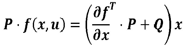
Unter Annahme des Reglergesetzes aus Gleichung (3) lässt sich als Bedingung für die Optimalitätserhaltung formulieren: 
Sofern eine Matrix P existiert, sodass ![]()
![]()
Nun wird die Anwendung der Bedingungen beschrieben. Bei der Suche nach der Funktion R̃(x) kann nun ausgehend von den lokalen Reglermatrizen R̃AP als Startwerte eine Optimierung der interpolierten Funktion R̃(x) vorgenommen werden. Hierbei werden die formulierten Bedingungen zur lokalen Stabilitäts- und Dämpfungserhaltung, sowie die Optimalitätsbedingungen ausgewertet und eine neue Position der Stützstellen in R̃(x) gefunden. Diese Optimierung lässt sich mit Gauss-Prozessen aufgrund der einfachen Rechenbarkeit der Steigungsfunktion mit deutlich verringerter Rechenlast durchführen.Now the application of the conditions will be described. In the search for the function R ( x ), it is now possible to optimize the interpolated function R ( x ) starting from the local controller matrices R AP as start values. Here, the formulated conditions for local stability and attenuation conservation, as well as the optimality conditions are evaluated and a new position of the interpolation points in R ( x ) is found. This optimization can be carried out with Gauss processes due to the simple calculability of the slope function with significantly reduced computational load.
Interessant ist dies besonders für Systeme, bei denen klassischerweise eine Vorsteuerung bereits existiert und man die Vermutung hat, dass die Parametrierung der Reglermatrix R̃(x) über einer Untermenge des Zustandsvektors möglich ist.This is particularly interesting for systems in which a precontrol traditionally already exists and one has the assumption that the parameterization of the controller matrix R ( x ) over a subset of the state vector is possible.
Die notwendige Anzahl an Zustandsvariablen ist äquivalent zur Anzahl der Stellgrößen u, damit die Betriebsbereiche eindeutig identifiziert werden können. Eine erste Einschätzung für die Wahl der jeweiligen Zustandsvariablen gibt die Korrelation der lokal linearen Reglerparameter p aus R̃AP mit den jeweiligen Zustandsgrößen.The necessary number of state variables is equivalent to the number of manipulated variables u, so that the operating ranges can be uniquely identified. A first assessment for the choice of the respective state variables gives the correlation of the locally linear controller parameter p from R AP with the respective state variables.
Erfahrungsgemäß sollte bei der Wahl einer Zustandsgröße diejenige gewählt werden, für die sich jeweils einen möglichst monotonen und stetigen Verlauf bezüglich des Reglerparameters p zeigt.According to experience, when choosing a state variable, the one should be selected for which a possibly monotonous and continuous course with respect to the controller parameter p is shown.
Als technisches Beispiel wird zur Anwendung des Verfahrens gemäß dem Schema in
Der Turbolader 200 weist turbinenseitig ein Turbinenrad und verdichterseitig ein Verdichterrad auf, die auf einer Welle miteinander verbunden sind.The
Der Unterschied zum herkömmlichen Turbolader besteht darin, dass der VTG-Lader auf der Eingangsseite der Turbine 300 verstellbare Leitschaufeln besitzt. Die Verstellung bewirkt, dass das Turbinenrad immer optimal durch das Abgas angeströmt wird, auch wenn unterschiedliche Abgasmengen zu Verfügung stehen beziehungsweise die Turbine 300 durchströmen. Bei kleiner Abgasmenge werden die Leitschaufeln auf flach gestellt, das heißt die Verstellposition der Leitschaufeln als Stellgröße u3 verändert sich, und es ergibt sich für die Abgase der Verbrennungskraftmaschine 100 ein geringerer Querschnitt in den Schaufeln.The difference to the conventional turbocharger is that the VTG loader on the input side of the
Damit in derselben Zeiteinheit, eine gleiche Abgasmenge durch die Leitschaufeln strömen kann, muss die geringe Abgasmenge schneller strömen. Das führt zur schnelleren Anströmung und damit schnelleren Drehung des Turbinenrads, wodurch auf der Verdichterseite mehr Medium gefördert und ein höherer Ladedruck erreicht wird. Das geschieht also beispielsweise bei niedrigen Drehzahlen und Volllast, wenn ein schneller 'Ladedruckaufbau' (= Steigerung des Ladedrucks) benötigt wird. Mit zunehmender Abgasmenge werden die Leitschaufeln steiler gestellt, so dass sich wiederum die Verstellposition der Leitschaufeln als Stellgröße u3 verändert. Der Querschnitt vergrößert sich, die Anströmung des Turbinenrades bleibt aber optimal und der Ladedruck x3, sowie die Turbinenleistung bleiben annähernd konstant.So that in the same time unit, an equal amount of exhaust gas can flow through the vanes, the small amount of exhaust gas must flow faster. This leads to faster flow and thus faster rotation of the turbine wheel, which promotes more medium on the compressor side and a higher boost pressure is achieved. This happens, for example, at low speeds and full load, if a quick 'boost pressure build-up' (= increase in boost pressure) is needed. As the amount of exhaust gas increases, the guide vanes become steeper so that in turn the adjustment position of the guide vanes changes as the manipulated variable u3. The cross-section increases, but the flow of the turbine wheel remains optimal and the boost pressure x3, as well as the turbine power remain approximately constant.
Das gewählte technische Ausführungsbeispiel betrifft einen Dieselmotor, da die Verwendung von VTG-Ladern ein im Dieselbereich oft verwendete Technologie darstellt. Es wird jedoch darauf hingewiesen, dass die technische Lösung auch für einen Ottomotor angewendet werden kann. Mit anderen Worten die erfindungsgemäße Lösung wird für Otto-Fahrzeuge und Diesel-Fahrzeug gleichermaßen beansprucht.The selected technical embodiment relates to a diesel engine, since the use of VTG superchargers represents a technology often used in the diesel field. However, it should be noted that the technical solution can also be applied to a gasoline engine. In other words, the solution according to the invention is equally claimed for petrol vehicles and diesel vehicles.
Das Ausführungsbeispiel betrifft somit die Ladedruckregelung eines VTG-Laders 200, 300 und gleichzeitiger Regelung mindestens einer Abgasrückführungsrate, insbesondere einer Abgasrückführungsrate über eine Hochdruckabgasrückführungs-Leitung mittels einer Hochdruck-AGR-Regelung und/oder einer Abgasrückführungsrate über eine Niederdruckabgasrückführungs-Leitung NL mittels einer Niederdruck-Abgasrückführungs-Regelung bei einem Otto-Motor oder einem Diesel-Motor.The embodiment thus relates to the boost pressure control of a
Die Regelungsaufgabe wird hierbei als Mehrgrößenregelung aufgefasst, die mit dem erfindungsgemäßen Verfahren besonders vorteilhaft gelöst werden kann.The control task is here understood as a multi-variable control, which can be solved particularly advantageous with the method according to the invention.
Für diese wird ein Zustandsraummodell gemäß Gleichung (0) entworfen mit den Zustandsgrößen x, wobei mehrere Zustandsgrößen berücksichtigt werden.For these, a state space model according to equation (0) is designed with the state variables x, taking into account a plurality of state variables.
Nachfolgend werden einige Zustandsgrößen x1 bis x5 genannt, die in bevorzugter Ausgestaltung der Erfindung bei der genannten Anwendung berücksichtigt werden. Es versteht sich, dass darüber hinaus noch weitere hier nicht genannte Zustandsgrößen berücksichtigt werden können.Hereinafter, some state variables x1 to x5 are mentioned, which are considered in a preferred embodiment of the invention in the said application. It goes without saying that, in addition, further state variables not mentioned here can be taken into account.
Beispielsweise werden die Zustandsgröße/n x1 bis x5 dem Regler 14 zugeführt und wirken auf die Regelstrecke (12).For example, the state variable / n x1 to x5 are supplied to the
Eine Zustandsgröße (vgl.
Eine weitere Zustandsgröße (vgl.
Des Weiteren wird (vgl.
Es versteht sich, dass die Zustandsgrößen x1, x2, x3 bei einer Niederdruck-Abgasrückführung über die Abgasrückführungsleitung NL (vgl.
Außerdem ist vorgesehen, dass zur Ladedruckregelung und Hochdruck-Abgasrückführungs-Regelung ein Druck x4 des Abgases der Verbrennungskraftmaschine 100 vor der Turbine 300 mit variabler Turbinengeometrie in der Abgasleitung AL berücksichtigt und dem Regler 14 zugeführt wird.It is also provided that for boost pressure control and high-pressure exhaust gas recirculation control a pressure x4 of the exhaust gas of the
Schließlich wird zur Ladedruckregelung und zur Niederdruck-AGR-Regelung ein Druck x5 nach der Turbine 300 mit variabler Turbinengeometrie in der Abgasleitung AL ermittelt, dem Regler 14 zugeführt, der somit bei der Ladedruckregelung und der Niederdruck-AGR-Regelung berücksichtigt wird.Finally, for boost pressure control and for low-pressure EGR control, a pressure x5 is determined downstream of
Erfindungsgemäß werden, je nachdem ob eine Hochdruck-AGR-Regelung und/oder eine Niederdruck-AGR-Regelung berücksichtigt werden soll, Stellgrößen u gemessen und berücksichtigt, wobei bevorzugt mehrere Stellgrößen u1, u2, u3 berücksichtigt werden, die dem Regler 14 zurückgeführt werden und auf die Regelstrecke 12 wirken.According to the invention, depending on whether a high-pressure EGR control and / or a low-pressure EGR control is to be taken, control variables u are measured and taken into account, wherein preferably a plurality of control variables u1, u2, u3 are taken into account, which are fed back to the
Es wird zur Regelung der Abgasrückführungsrate (vgl.
Ferner wird zur Regelung der Abgasrückführungsrate, insofern eine Niederdruck-AGR vorgesehen ist, eine Ventilposition u2 eines Ventils V2 in der Abgas-Rückführungsleitung NL der Niederdruck Abgasrückführung (vgl.
Schließlich wird als Stellgröße u zur Ladedruckregelung, die bereits erläuterte Verstellposition u3 der Turbine 300 mit variabler Turbinengeometrie berücksichtigt, wobei die Verstellposition u3 in der genannten Ausgestaltung über die Erfassung der Positionierung der Leitschaufeln der Turbine 300 erfolgt.Finally, as a manipulated variable u for boost pressure control, the previously described adjustment position u3 of the
Als Vorsteuerung wird bevorzugt die stationäre Leistungsbilanz des Turboladers 200, 300 mit einem eigens formulierten Kennfeld für die VTG-Position der Turbine 300 aus Druckverhältnis und dem Turbinenmassenstrom sowie das inverse Modell des Soll-Hochdruck/Niederdruck-AGR-Massenstroms gewählt.As pre-control, the stationary power balance of the
Für das Design der Funktionen R̃(x) wurden die Turboladerdrehzahl x2 und die Ist-AGR-Ventilposition(en) u1, u2 als gute Zustandsgrößen x beziehungsweise Stellgrößen u zum Scheduling der Reglerparameter p ermittelt, die gleichzeitig die Bedingungen der lokalen Stabilitäts- und Dämpfungserhaltung und der globalen Optimalität nach eigener Optimierung der Kennfeldverläufe der Reglerparameter p in R(x) erfüllen.For the design of the functions R ( x ), the turbocharger speed x2 and the actual EGR valve position (s) u1, u2 were determined as good state variables x and manipulated variables u for scheduling the controller parameters p, which simultaneously satisfy the conditions of the local Stability and attenuation maintenance and the global optimality after own optimization of the characteristic curves of the controller parameters p in R (x) meet.
Weiterhin können ein Gain-Scheduling und eine Vorsteuerung in dem Steuergerät 11 realisiert sein.Furthermore, a gain scheduling and a feedforward control can be realized in the
Das Steuergerät 11 kann zum Beispiel für ein Kraftfahrzeug, beispielsweise ein Motorsteuergerät eines als Verbrennungskraftmaschine 100 vorgesehenen Diesel-Motors vorgesehen sein.The
Das Steuergerät 11 regelt die Regelstrecke 12, die beispielsweise eine Ladedruckregelung und eine gleichzeitige Hochdruck-AGR-Regelung und optional wie erläutert eine Niederdruck-AGR-Regelung umfasst. In einigen Anwendungsfällen ist eine Ladedruckregelung ausschließlich mit einer gleichzeitige Niederdruck-AGR-Regelung verknüpft. Es wird deutlich, dass das Verfahren variabel für alle Anwendungsfälle einsetzbar ist.The
Das Steuergerät 11 umfasst, die vorhergehenden Ausführungen zusammengefasst den Regler 14, dem die jeweiligen Stellgrößen u (u1, u2, u3) zugeführt werden, die auf die Regelstrecke 12 wirken.The
Zustandsgrößen x (x1, x2, x3, x4, x5), die gemessen oder geschätzt werden, werden unter Zusammenfassung der vorhergehenden Ausführungen ebenfalls dem Regler 14 zurückgeführt und wirken auf die Regelstrecke 12.State variables x (x1, x2, x3, x4, x5), which are measured or estimated, are also fed back to the
Regelgrößen y werden aus der Regelstrecke 12 ausgegeben und im Regelkreis zurückgeführt.Controlled variables y are output from the controlled
Die Regelgrößen y werden von Sollgrößen oder Führungsgrößen w subtrahiert, wodurch sich die Regelabweichung e ergibt, welche dem Regler 14 zugeführt wird.The controlled variables y are subtracted from nominal values or reference variables w, which results in the control deviation e, which is supplied to the
Ein Reglerparameter-Generator 16 erzeugt Reglerparameter p für den Regler 14.A
Aus der Regelstrecke 12 werden Größen der Regelstrecke 12 beziehungsweise Scheduling-Größen s dem Reglerparameter-Generator 16 zugeführt.From the controlled
Der Reglerparameter-Generator 16 umfasst mehrere Gauß-Prozess-Modelle 18 zur Bestimmung der Reglerparameter p in Abhängigkeit der Größen s der Regelstrecke 12. Der Regler 14 ist als Mehrgrößenregler ausgeführt. Entsprechend ist für jede Größe ein Reglerparameter p, ein Gauß-Prozess-Modell 18 sowie eine Scheduling-Größe s vorgesehen.The
Der Reglerparameter-Generator 16 bestimmt online, das heißt während des Betriebs der Regelstrecke 12, in jedem Rechenschritt die Reglerparameter p in Abhängigkeit von den zugeführten Scheduling-Größen s, wobei die Reglerparameter P die Ausgänge der Gauß-Prozess-Modelle 18 sind.The
Zusätzlich enthält das Steuergerät 11 gemäß
In einem Knoten, wie zum Beispiel einem Addierer, werden verfügbare Messgrößen m der Regelstrecke 12 von den modellierten Messgrößen m' des Modells 22 subtrahiert. Das Ergebnis ist ein Messfehler oder Fehlersignal f, welches einem Schätzverstärker 24 zugeführt wird.In a node, such as an adder, available measurands m of the controlled
Der Schätzverstärker 24 enthält, wie
In diesem zweiten Ausführungsbeispiel wird die vollständige Rückführung der Zustandsgrößen x (x1, x2, x3, x4, x5) der Regelstrecke 12 durch den Beobachter 20 realisiert. Dazu werden die Verstärkungsfaktoren, die zur Konvergenz des Schätzfehlers über die Generierung eines zusätzlichen Stellanteils u' in der Beobachterstruktur des Beobachters 20 führen, als Gauß-Prozessor 18 modelliert.In this second embodiment, the complete feedback of the state variables x (x1, x2, x3, x4, x5) of the controlled
In
Das Scheduling und die eigentliche Reglerstruktur sind damit zusammengeführt. Als Modellanteile des Reglers 14 können Kanäle des Reglers angesehen werden, die zu einer oder mehreren Größen eines Mehrgrößenreglers korrespondieren. Weiter können als Modellanteile des Reglers 14 einzelne Bestandteile innerhalb eines Kanals angesehen werden.The scheduling and the actual controller structure are merged with it. As a model of the
Die Wahrscheinlichkeitswerte, die seitens der Gauss-Prozess-Modellierung 18 ermittelt werden, liefern eine Aussage über die Güte des ermittelten Parameterwertes, insbesondere des Reglerparameters p. Daher können diese Wahrscheinlichkeitswerte innerhalb der Reglerstruktur direkt verwendet werden, um bei geringer Modellierungsgüte ein konservativeres (stärker gedämpftes) Verhalten der geregelten Regelstrecke 12 zu erzeugen. Hierfür werden die ermittelten Reglerparameter p in Abhängigkeit der Wahrscheinlichkeitswerte in einer eigenen Funktionalität des Reglers 14 so variiert, dass die Dämpfung des nominellen geregelten Systems erhöht wird.The probability values that are determined by the
- 100100
- VerbrennungskraftmaschineInternal combustion engine
- 200200
- Turbolader (Verdichter)Turbocharger (compressor)
- 300300
- Turbine mit variabler TurbinengeometrieTurbine with variable turbine geometry
- 400400
- Luftfilterair filter
- V1V1
- Ventil in Hochdruck-Abgasrückführungsleitung HLValve in high-pressure exhaust gas recirculation line HL
- V2V2
- Ventil in Niederdruck-Abgasrückführungsleitung NLValve in low-pressure exhaust gas recirculation line NL
- HLHL
- Abgas-Rückführungsleitung der Hochdruck-AbgasrückführungExhaust gas recirculation line of the high-pressure exhaust gas recirculation
- NLNL
- Abgas-Rückführungsleitung der Niederdruck-AbgasrückführungExhaust gas recirculation line of the low-pressure exhaust gas recirculation
- FLFL
- FrischluftleitungFresh air line
- ALAL
- Abgasleitungexhaust pipe
- 1010
- Regelkreisloop
- 1111
- Steuergerätcontrol unit
- 1212
- Regelstreckecontrolled system
- 1414
- Reglerregulator
- 1616
- Reglerparameter-GeneratorController parameter generator
- 1818
- Gauß-Prozess-ModellGaussian process model
- 2020
- Beobachterobserver
- 2222
- Modellmodel
- 2424
- Schätzverstärkerestimated amplifier
- ee
- Regelabweichungdeviation
- ff
- Fehlersignalerror signal
- mm
- Messgrößemeasurand
- m'm '
- modellierte Messgrößemodeled measurand
- pp
- Reglerparametercontroller parameters
- ss
- Scheduling-GrößeScheduling Size
- uu
- Stellgrößemanipulated variable
- u1u1
- Ventilposition des Ventils V1Valve position of the valve V1
- u2u2
- Ventilposition des Ventils V2Valve position of valve V2
- u3u3
-
Verstellposition der Turbine 300Adjustment position of the
turbine 300 - u'u '
- Stellgröße BeobachterManipulated variable observer
- ww
- Sollgrößeintended size
- xx
- Zustandsgrößestate variable
- x1x1
-
Druck vor dem Turbolader 200Pressure in front of the
turbocharger 200 - x2x2
-
Drehzahl des Turboladers 200Speed of the
turbocharger 200 - x3x3
-
Druck nach dem Turbolader 200Pressure after the
turbocharger 200 - x4x4
-
Druck vor der Turbine 300Pressure in front of the
turbine 300 - x5x5
-
Druck nach der Turbine 300Pressure after the
turbine 300 - yy
- Regelgrößecontrolled variable
Claims (19)
dadurch gekennzeichnet, dass
zur Bestimmung der Reglerparameter (p) in Abhängigkeit der Größen (s) der Regelstrecke (12) mindestens ein Gauss-Prozess-Modell (18) in einer dafür eingerichteten Vorrichtung (16) zur Bestimmung der Reglerparameter (p) verwendet wird, wobei die bestimmten Reglerparameter (p) die Ausgänge der Gauß-Prozess-Modelle (18) sind.Method for boost pressure control of a turbocharger (200, 300) with variable turbine geometry (VTG) of an internal combustion engine (100), the controller parameter (p) of which is controlled by regulating a controlled system (12) with a controller (14) as a function of variables (s) of the controlled system ( 12) vary,
characterized in that
at least one Gaussian process model (18) is used to determine the controller parameters (p) as a function of the variables (s) of the controlled system (12) in a device (16) arranged therefor for determining the controller parameters (p), wherein the determined Controller parameters (p) are the outputs of the Gaussian process models (18).
dadurch gekennzeichnet, dass
die Ladedruckregelung des Turboladers (200, 300) mit variabler Turbinengeometrie (VTG) gleichzeitig mit der Regelung mindestens einer Abgasrückführungsrate einer Abgasrückführung (Hochdruck-Abgasrückführung und/oder Niederdruck-AGR) der Verbrennungskraftmaschine (100) vorgenommen wird, deren Reglerparameter (p) beim Regeln der Regelstrecke (12) mit dem Regler (14) in Abhängigkeit von Größen (s) der Regelstrecke (12) variieren.Method according to claim 1,
characterized in that
the boost pressure control of the turbocharger (200, 300) with variable turbine geometry (VTG) is carried out simultaneously with the regulation of at least one exhaust gas recirculation rate of exhaust gas recirculation (high-pressure exhaust gas recirculation and / or low-pressure EGR) of the internal combustion engine (100), the controller parameter (p) of which is regulated the control path (12) with the controller (14) in dependence on variables (s) of the controlled system (12) vary.
dadurch gekennzeichnet, dass
in Abhängigkeit von auf die Regelstrecke (12) wirkenden Stellgrößen (u; u1, u2, u3) mittels eines Beobachters (20) in die Regelstrecke (12) einfließende Zustandsgrößen (x; x1, x2, x3, x4, x5) geschätzt oder gemessen werden, die zu dem Regler (14) zurückgeführt werden, wobei der Beobachter (20) über mindestens ein Gauss-Prozess-Modell (18) Verstärkungsfaktoren modelliert.Method according to claim 1 or 2,
characterized in that
depending on manipulated variables (u; u1, u2, u3) acting on the controlled system (12), estimated or measured state variables (x; x1, x2, x3, x4, x5) flowing into the controlled system (12) by means of an observer (20) which are returned to the controller (14), the observer (20) modeling gain factors via at least one Gaussian process model (18).
dadurch gekennzeichnet, dass
zur Ladedruckregelung des Turboladers (200) als Zustandsgröße/n (x; x1, x2, x3, x4, x5), die dem Regler (14) zugeführt wird/werden und die auf die Regelstrecke (12) wirkt/wirken,
characterized in that
for boost pressure control of the turbocharger (200) as a state variable / n (x; x1, x2, x3, x4, x5) which is / are supplied to the controller (14) and which acts on the controlled system (12),
dadurch gekennzeichnet, dass
zur Ladedruckregelung des Turboladers (200) und zur Regelung der Abgasrückführungsrate als Zustandsgröße/n (x; x1, x2, x3, x4, x5), die dem Regler (14) zugeführt wird/werden und die auf die Regelstrecke (12) wirkt/wirken,
characterized in that
for boost pressure control of the turbocharger (200) and for regulating the exhaust gas recirculation rate as a state variable / n (x; x1, x2, x3, x4, x5) which is / are fed to the controller (14) and acts on the controlled system (12) / Act,
dadurch gekennzeichnet, dass
zur Ladedruckregelung des Turboladers (200) als Stellgröße (u; u3), die dem Regler (14) zurückgeführt wird und die auf die Regelstrecke (12) wirkt,
characterized in that
for boost pressure control of the turbocharger (200) as manipulated variable (u; u3), which is fed back to the controller (14) and which acts on the controlled system (12),
dadurch gekennzeichnet, dass
zur Regelung der Abgasrückführungsrate als Stellgröße/n (u; u1, u2), die dem Regler (14) zurückgeführt wird/werden und die auf die Regelstrecke (12) wirkt/wirken,
characterized in that
for regulating the exhaust gas recirculation rate as manipulated variable / n (u; u1, u2), which is / are returned to the controller (14) and which acts on the controlled system (12),
dadurch gekennzeichnet, dass
Regelgrößen (y) aus der Regelstrecke (12) ausgegeben und im Regelkreis zurückgeführt werden, wobei die Regelgrößen (y) von Sollgrößen oder Führungsgrößen (w) subtrahiert werden, wodurch sich eine Regelabweichung (e) ergibt, welche dem Regler (14) zugeführt wird.Method according to claim 1 or 2,
characterized in that
Control variables (y) from the controlled system (12) output and fed back in the control loop, wherein the control variables (y) of desired quantities or reference variables (w) are subtracted, resulting in a control deviation (e), which is supplied to the controller (14) ,
dadurch gekennzeichnet, dass
die Vorrichtung (16) Reglerparameter (p) für den Regler (14) bestimmt, wobei der Vorrichtung (16) aus der Regelstrecke (12) Regelgrößen (y) zugeführt werden, wobei mindestens eine der Größen der Regelstrecke (12) der Vorrichtung (16) als Scheduling-Größe (s) zugeführt wird.Method according to claim 1 or 2,
characterized in that
the device (16) determines controller parameters (p) for the controller (14), wherein the device (16) from the controlled system (12) controlled variables (y) are supplied, wherein at least one of the variables of the controlled system (12) of the device (16 ) is supplied as the scheduling size (s).
dadurch gekennzeichnet, dass
die Vorrichtung (16) während des Betriebs der Regelstrecke (12), in jedem Rechenschritt die Reglerparameter (p) in Abhängigkeit von der mindestens einen zugeführten Scheduling-Größe (s) online bestimmt.Method according to claim 9 or 10,
characterized in that
during operation of the controlled system (12), the device (16) determines the controller parameters (p) online in each computing step as a function of the at least one supplied scheduling variable (s).
dadurch gekennzeichnet, dass
der Beobachter (20) zur Schätzung der Zustandsgrößen (x; x1, x2, x3, x4, x5), der Regelstrecke (12) ein Modell (22) enthält, welches die Zustandsgrößen (x; x1, x2, x3, x4, x5), und modellierte Messgrößen (m') an den Regler (14) ausgibt, wobei verfügbare Messgrößen (m) der Regelstrecke (12) von den modellierten Messgrößen (m') des Modells (22) subtrahiert werden, wonach im Ergebnis einem Schätzverstärker (24) ein Messfehler oder ein Fehlersignal (f) zugeführt wird.Method according to claim 3,
characterized in that
the observer (20) for estimating the state variables (x; x1, x2, x3, x4, x5), the controlled system (12) contains a model (22) which the state variables (x; x1, x2, x3, x4, x5 ), and outputs modeled measurands (m ') to the controller (14), whereby available measured quantities (m) of the controlled system (12) are subtracted from the modeled measurands (m') of the model (22), as a result of which an estimation amplifier ( 24) a measurement error or an error signal (f) is supplied.
dadurch gekennzeichnet, dass
der Schätzverstärker (24) analog zu der Vorrichtung (16) mehrere Gauss-Prozess-Modelle (18) aufweist, welche Verstärkungsfaktoren beziehungsweise Stellgrößen (u') des Beobachters (20) erzeugen, so dass eine vollständige Rückführung der Zustandsgrößen (x; x1, x2, x3, x4, x5) der Regelstrecke (12) durch den Beobachter (20) durchgeführt wird, wozu die Verstärkungsfaktoren, die zur Konvergenz des Schätzfehlers über die Generierung eines zusätzlichen Stellanteils (u') in der Struktur des Beobachters (20) führen, wiederum als Gauss-Prozessor modelliert werden.Method according to claim 12,
characterized in that
the estimation amplifier (24) has a plurality of Gaussian process models (18) analogous to the device (16), which generate amplification factors or manipulated variables (u ') of the observer (20), so that complete feedback of the state variables (x; x2, x3, x4, x5) of the controlled system (12) is performed by the observer (20), for which the gain factors that lead to the convergence of the estimation error on the generation of an additional control component (u ') in the structure of the observer (20) , again modeled as a Gaussian processor.
dadurch gekennzeichnet, dass
mindestens ein Modellanteil oder mehrere Modellanteile des Reglers (14) als Gauss-Prozess-Modell (18) ausgeführt ist/sind, wobei das Scheduling nach mindestens einem der Ansprüche 9 bis 11 als Element oder Funktionsanteil innerhalb des Reglers (14) realisiert wird, so dass das Scheduling und die Reglerstruktur zusammengeführt sind, wobei der mindestens eine Modellanteil oder die mehreren Modellanteile des Reglers (14) Kanäle des Reglers (14) sind, die zu einer oder mehreren Größe/n eines Mehrgrößenreglers korrespondieren, wobei die Modellanteile des Reglers (14) als Bestandteile innerhalb eines Kanals fungieren.Method according to at least one of claims 9 to 11,
characterized in that
at least one model component or several model components of the controller (14) is / are designed as a Gaussian process model (18), wherein the scheduling according to at least one of claims 9 to 11 is realized as an element or functional component within the controller (14), then in that the scheduling and the controller structure are combined, wherein the at least one model component or the plurality of model components of the controller (14) are channels of the controller (14) which correspond to one or more sizes of a multivariable controller, the model components of the controller (14 ) function as components within a channel.
dadurch gekennzeichnet, dass
über Modellierung der Gauss-Prozess-Modelle (18) Wahrscheinlichkeitswerte ermittelt werden, die eine Aussage über Güte der ermittelten Reglerparameter (p) liefern, wobei diese Wahrscheinlichkeitswerte innerhalb der Reglerstruktur direkt verwendet werden, um bei einer geringen Modellierungsgüte ein konservativeres, insbesondere stärker gedämpftes Verhalten der geregelten Regelstrecke (12) zu erzeugen, wozu die ermittelten Reglerparameter (p) in Abhängigkeit der Wahrscheinlichkeitswerte in einer eigenen Funktionalität des Reglers (14) variiert werden, so dass die Dämpfung des nominellen geregelten Systems erhöht wird.Method according to claim 1 or 2,
characterized in that
By modeling the Gaussian process models (18), probability values can be determined which provide information about the quality of the determined controller parameters (p), whereby these probability values are used directly within the controller structure in order to achieve a more conservative, and in particular more attenuated, behavior with a low modeling quality the controlled controlled system (12) to generate what the determined controller parameters (p) in dependence of the probability values in a individual functionality of the controller (14) are varied so that the attenuation of the nominal controlled system is increased.
dadurch gekennzeichnet, dass
das Steuergerät (11) als Vorrichtung einen die Reglerparameter (p) für den Regler (14) bestimmenden Reglerparameter-Generator (16) umfasst, wobei der Reglerparameter-Generator (16) mindestens ein Gauss-Prozess-Modell (18) aufweist, wobei der Reglerparameter-Generator (16) zur Bestimmung der Reglerparameter (p) in Abhängigkeit mindestens einer Größe (s) der Regelstrecke (12) eingerichtet ist, wobei die bestimmten Reglerparameter (p) die Ausgänge der Gauß-Prozess-Modelle (18) sind.Control unit, set up for use in a vehicle, in particular a motor control unit, which varies a controller (14) whose controller parameter (p) varies as a function of variables (s) of a controlled system (12), and a device (16) for generating controller parameters ( p) for the controller (14),
characterized in that
the control unit (11) comprises, as a device, a controller parameter generator (16) determining the controller parameters (p) for the controller (14), wherein the controller parameter generator (16) has at least one Gaussian process model (18) Controller parameter generator (16) for determining the controller parameters (p) is set up as a function of at least one size (s) of the controlled system (12), wherein the specific controller parameters (p) are the outputs of the Gaussian process models (18).
dadurch gekennzeichnet, dass
ein Beobachter (20) zur Schätzung von Zustandsgrößen (x; x1, x2, x3, x4, x5), der Regelstrecke (12) vorgesehen ist, und dass die geschätzten Zustandsgrößen (x; x1, x2, x3, x4, x5), zu dem Regler (14) zugeführt werden, wobei der Beobachter (20) mindestens ein Gauss-Prozess-Modell (18) aufweist, welches zur Modellierung von Verstärkungsfaktoren eingerichtet ist.Control device according to claim 16,
characterized in that
an observer (20) is provided for estimating state variables (x; x1, x2, x3, x4, x5) of the controlled system (12) and that the estimated state variables (x; x1, x2, x3, x4, x5), to the controller (14), wherein the observer (20) comprises at least one Gaussian process model (18) adapted to model gain factors.
dadurch gekennzeichnet, dass
mindestens ein Modellanteil des Reglers (14) als Gauss-Prozess-Modell (18) ausgebildet ist.Control device according to Claim 16 or 17, characterized
characterized in that
at least one model portion of the controller (14) is designed as a Gaussian process model (18).
dadurch gekennzeichnet, dass
die Regelstrecke (12) eine Ladedruckregelung eines Turboladers (200, 300) mit variabler Turbinengeometrie (VTG) nach Anspruch 1 oder eine Ladedruckregelung eines Turboladers (200, 300) mit variabler Turbinengeometrie (VTG) und gleichzeitiger Regelung einer Abgasrückführungsrate mindestens einer Abgasrückführung (AGR) einer Verbrennungskraftmaschine (100) nach den Ansprüchen 1 und 2 umfasst.Control device according to claim 16,
characterized in that
the controlled system (12) has a boost pressure control of a turbocharger (200, 300) with variable turbine geometry (VTG) according to claim 1 or boost pressure control of a turbocharger (200, 300) with variable turbine geometry (VTG) and simultaneous regulation of an exhaust gas recirculation rate of at least one exhaust gas recirculation (EGR) an internal combustion engine (100) according to claims 1 and 2.
Applications Claiming Priority (1)
| Application Number | Priority Date | Filing Date | Title |
|---|---|---|---|
| DE102015203210.8A DE102015203210A1 (en) | 2015-02-23 | 2015-02-23 | Method for regulating a controlled system, device for generating controller parameters and control device |
Publications (3)
| Publication Number | Publication Date |
|---|---|
| EP3062176A2 true EP3062176A2 (en) | 2016-08-31 |
| EP3062176A3 EP3062176A3 (en) | 2017-03-08 |
| EP3062176B1 EP3062176B1 (en) | 2019-07-03 |
Family
ID=55411278
Family Applications (1)
| Application Number | Title | Priority Date | Filing Date |
|---|---|---|---|
| EP16156713.6A Active EP3062176B1 (en) | 2015-02-23 | 2016-02-22 | Method for adjusting a control loop, device for generating control parameters and control device |
Country Status (2)
| Country | Link |
|---|---|
| EP (1) | EP3062176B1 (en) |
| DE (1) | DE102015203210A1 (en) |
Cited By (7)
| Publication number | Priority date | Publication date | Assignee | Title |
|---|---|---|---|---|
| CN108073071A (en) * | 2016-11-18 | 2018-05-25 | 罗伯特·博世有限公司 | For performing to adjust the method and apparatus of the position adjusting of transmitter unit |
| CN108241294A (en) * | 2016-12-23 | 2018-07-03 | 罗伯特·博世有限公司 | The method and apparatus adjusted for the position of electromechanical alignment system |
| WO2019076511A1 (en) * | 2017-10-20 | 2019-04-25 | Robert Bosch Gmbh | Method and device for setting at least one parameter of an actuator control system and actuator control system |
| EP3536937A1 (en) * | 2018-03-07 | 2019-09-11 | Toyota Jidosha Kabushiki Kaisha | Control device of internal combustion engine |
| EP3617488A1 (en) * | 2018-08-29 | 2020-03-04 | Toyota Jidosha Kabushiki Kaisha | Control device for internal combustion engine and control method for internal combustion engine |
| WO2020064566A1 (en) * | 2018-09-27 | 2020-04-02 | Mtu Friedrichshafen Gmbh | Method for the model-based open-loop and closed-loop control of an internal combustion engine with an scr catalytic converter |
| WO2021148410A1 (en) * | 2020-01-21 | 2021-07-29 | Mtu Friedrichshafen Gmbh | Method for the model-based open-loop and closed-loop control of an internal combustion engine |
Citations (3)
| Publication number | Priority date | Publication date | Assignee | Title |
|---|---|---|---|---|
| US20050193739A1 (en) | 2004-03-02 | 2005-09-08 | General Electric Company | Model-based control systems and methods for gas turbine engines |
| US20070276512A1 (en) | 2006-05-25 | 2007-11-29 | Honeywell Asca Inc. | Automatic tuning method for multivariable model predictive controllers |
| DE102010028266A1 (en) | 2010-04-27 | 2011-10-27 | Robert Bosch Gmbh | Control device and method for calculating an output for a controller |
Family Cites Families (6)
| Publication number | Priority date | Publication date | Assignee | Title |
|---|---|---|---|---|
| DE10238573B4 (en) * | 2002-08-22 | 2004-08-05 | Siemens Ag | Method for adapting control parameters of a boost pressure regulator in an internal combustion engine with an exhaust gas turbocharger |
| JP4184058B2 (en) * | 2002-12-05 | 2008-11-19 | 本田技研工業株式会社 | Control device |
| CN101432726B (en) * | 2006-04-24 | 2013-04-03 | 通用汽车环球科技运作公司 | Airflow estimation method and apparatus for internal combustion engine |
| DE102008001081B4 (en) * | 2008-04-09 | 2021-11-04 | Robert Bosch Gmbh | Method and engine control device for controlling an internal combustion engine |
| DE102008043315A1 (en) * | 2008-10-30 | 2010-05-06 | Robert Bosch Gmbh | Method for operating internal combustion engine, particularly for motor vehicle, involves detecting combustion chamber pressure within combustion chamber of combustion engine |
| DE102013214967A1 (en) * | 2013-07-31 | 2015-02-19 | Robert Bosch Gmbh | Method and device for adapting a data-based function model |
-
2015
- 2015-02-23 DE DE102015203210.8A patent/DE102015203210A1/en not_active Withdrawn
-
2016
- 2016-02-22 EP EP16156713.6A patent/EP3062176B1/en active Active
Patent Citations (3)
| Publication number | Priority date | Publication date | Assignee | Title |
|---|---|---|---|---|
| US20050193739A1 (en) | 2004-03-02 | 2005-09-08 | General Electric Company | Model-based control systems and methods for gas turbine engines |
| US20070276512A1 (en) | 2006-05-25 | 2007-11-29 | Honeywell Asca Inc. | Automatic tuning method for multivariable model predictive controllers |
| DE102010028266A1 (en) | 2010-04-27 | 2011-10-27 | Robert Bosch Gmbh | Control device and method for calculating an output for a controller |
Cited By (15)
| Publication number | Priority date | Publication date | Assignee | Title |
|---|---|---|---|---|
| CN108073071A (en) * | 2016-11-18 | 2018-05-25 | 罗伯特·博世有限公司 | For performing to adjust the method and apparatus of the position adjusting of transmitter unit |
| CN108073071B (en) * | 2016-11-18 | 2023-08-08 | 罗伯特·博世有限公司 | Method and device for performing a position adjustment for adjusting a transmitter unit |
| CN108241294A (en) * | 2016-12-23 | 2018-07-03 | 罗伯特·博世有限公司 | The method and apparatus adjusted for the position of electromechanical alignment system |
| US11550272B2 (en) | 2017-10-20 | 2023-01-10 | Robert Bosch Gmbh | Method and device for setting at least one parameter of an actuator control system and actuator control system |
| WO2019076511A1 (en) * | 2017-10-20 | 2019-04-25 | Robert Bosch Gmbh | Method and device for setting at least one parameter of an actuator control system and actuator control system |
| EP3536937A1 (en) * | 2018-03-07 | 2019-09-11 | Toyota Jidosha Kabushiki Kaisha | Control device of internal combustion engine |
| EP3617488A1 (en) * | 2018-08-29 | 2020-03-04 | Toyota Jidosha Kabushiki Kaisha | Control device for internal combustion engine and control method for internal combustion engine |
| CN110873014A (en) * | 2018-08-29 | 2020-03-10 | 丰田自动车株式会社 | Control device for internal combustion engine and control method for internal combustion engine |
| WO2020064566A1 (en) * | 2018-09-27 | 2020-04-02 | Mtu Friedrichshafen Gmbh | Method for the model-based open-loop and closed-loop control of an internal combustion engine with an scr catalytic converter |
| US11319888B2 (en) | 2018-09-27 | 2022-05-03 | Rolls-Royce Solutions GmbH | Method for the model-based open loop and closed loop control of an internal combustion engine |
| CN112739897A (en) * | 2018-09-27 | 2021-04-30 | Mtu 腓特烈港有限责任公司 | Method for model-based control and regulation of an internal combustion engine having an SCR catalyst |
| CN112739897B (en) * | 2018-09-27 | 2023-10-13 | 罗尔斯·罗伊斯解决方案有限公司 | Method for model-based control and regulation of an internal combustion engine having an SCR catalyst |
| CN114945741A (en) * | 2020-01-21 | 2022-08-26 | 罗尔斯·罗伊斯解决方案有限公司 | Method for model-based control and regulation of a combustion engine |
| WO2021148410A1 (en) * | 2020-01-21 | 2021-07-29 | Mtu Friedrichshafen Gmbh | Method for the model-based open-loop and closed-loop control of an internal combustion engine |
| US11846245B2 (en) | 2020-01-21 | 2023-12-19 | Rolls-Royce Solutions GmbH | Method for the model-based open-loop and closed-loop of an internal combustion engine |
Also Published As
| Publication number | Publication date |
|---|---|
| EP3062176A3 (en) | 2017-03-08 |
| DE102015203210A1 (en) | 2016-08-25 |
| EP3062176B1 (en) | 2019-07-03 |
Similar Documents
| Publication | Publication Date | Title |
|---|---|---|
| EP3062176B1 (en) | Method for adjusting a control loop, device for generating control parameters and control device | |
| EP2185980B1 (en) | Method for computer-aided control and/or regulation using neural networks | |
| DE10127788B4 (en) | Integrated optimal model predictive control in a process control system | |
| AT512251B1 (en) | Method of designing a nonlinear controller for non-linear processes | |
| DE102016121338B4 (en) | System and method for controlling an internal combustion engine and non-volatile storage medium | |
| DE602006000128T2 (en) | control | |
| DE102014205627B3 (en) | Condition observer for a steam generator of a steam power plant | |
| DE102015108381A1 (en) | Multi-variable control for low-pressure exhaust gas recirculation | |
| EP2880499B1 (en) | Method for controlling and/or regulating a technical system in a computer-assisted manner | |
| EP1896709B1 (en) | Method and apparatus for controlling an internal combustion engine | |
| EP1802859A1 (en) | Method for the operation of a fuel injection system especially of a motor vehicle | |
| DE102016123185A1 (en) | Machine-specific combined probabilistic control in gas turbine tuning for power output and emission parameters with scaling factor, associated control systems, computer program products and methods | |
| DE102020108243A1 (en) | Method and control unit for controlling a non-linear technical process | |
| WO1999060455A2 (en) | Method for generating connecting paths which can be used for guiding a vehicle to a predetermined target path | |
| EP3543514B1 (en) | Method and system for determining a variable for adjusting a suction pipe pressure | |
| WO2019057489A1 (en) | Method and training data generator for configuring a technical system, and control device for controlling the technical system | |
| DE102005026441B4 (en) | Method for adapting the pilot control map of a volume-flow-controlled diesel common rail pump | |
| EP3376026A1 (en) | Method for controlling the power output of a wind farm and corresponding wind farm | |
| DE102011076969B4 (en) | Method for computer-aided learning of a control and / or control of a technical system | |
| DE102009001644A1 (en) | Method and apparatus for correlating a cylinder charge and a maximum intake valve lift of an internal combustion engine | |
| DE102009054902A1 (en) | Method for setting functional parameters | |
| DE102008054630A1 (en) | Vehicle e.g. commercial vehicle, internal-combustion engine operating method, involves forming multiple condition variables of state space by multi-variable controller, and determining adjusting variable based on conditional variables | |
| DE602004011732T2 (en) | Control method for achieving a linear shear response | |
| DE102017003033A1 (en) | Method for processing signals and signal filters | |
| WO2017178015A1 (en) | Method and device for determining a technical system model |
Legal Events
| Date | Code | Title | Description |
|---|---|---|---|
| PUAI | Public reference made under article 153(3) epc to a published international application that has entered the european phase |
Free format text: ORIGINAL CODE: 0009012 |
|
| AK | Designated contracting states |
Kind code of ref document: A2 Designated state(s): AL AT BE BG CH CY CZ DE DK EE ES FI FR GB GR HR HU IE IS IT LI LT LU LV MC MK MT NL NO PL PT RO RS SE SI SK SM TR |
|
| AX | Request for extension of the european patent |
Extension state: BA ME |
|
| PUAL | Search report despatched |
Free format text: ORIGINAL CODE: 0009013 |
|
| AK | Designated contracting states |
Kind code of ref document: A3 Designated state(s): AL AT BE BG CH CY CZ DE DK EE ES FI FR GB GR HR HU IE IS IT LI LT LU LV MC MK MT NL NO PL PT RO RS SE SI SK SM TR |
|
| AX | Request for extension of the european patent |
Extension state: BA ME |
|
| RIC1 | Information provided on ipc code assigned before grant |
Ipc: F02D 41/14 20060101ALI20170127BHEP Ipc: F02D 41/00 20060101ALI20170127BHEP Ipc: F02D 41/26 20060101ALI20170127BHEP Ipc: G05B 13/04 20060101AFI20170127BHEP Ipc: G05B 13/02 20060101ALI20170127BHEP |
|
| STAA | Information on the status of an ep patent application or granted ep patent |
Free format text: STATUS: REQUEST FOR EXAMINATION WAS MADE |
|
| 17P | Request for examination filed |
Effective date: 20170908 |
|
| RBV | Designated contracting states (corrected) |
Designated state(s): AL AT BE BG CH CY CZ DE DK EE ES FI FR GB GR HR HU IE IS IT LI LT LU LV MC MK MT NL NO PL PT RO RS SE SI SK SM TR |
|
| STAA | Information on the status of an ep patent application or granted ep patent |
Free format text: STATUS: EXAMINATION IS IN PROGRESS |
|
| 17Q | First examination report despatched |
Effective date: 20171116 |
|
| GRAP | Despatch of communication of intention to grant a patent |
Free format text: ORIGINAL CODE: EPIDOSNIGR1 |
|
| STAA | Information on the status of an ep patent application or granted ep patent |
Free format text: STATUS: GRANT OF PATENT IS INTENDED |
|
| INTG | Intention to grant announced |
Effective date: 20181218 |
|
| GRAS | Grant fee paid |
Free format text: ORIGINAL CODE: EPIDOSNIGR3 |
|
| GRAA | (expected) grant |
Free format text: ORIGINAL CODE: 0009210 |
|
| STAA | Information on the status of an ep patent application or granted ep patent |
Free format text: STATUS: THE PATENT HAS BEEN GRANTED |
|
| AK | Designated contracting states |
Kind code of ref document: B1 Designated state(s): AL AT BE BG CH CY CZ DE DK EE ES FI FR GB GR HR HU IE IS IT LI LT LU LV MC MK MT NL NO PL PT RO RS SE SI SK SM TR |
|
| REG | Reference to a national code |
Ref country code: GB Ref legal event code: FG4D Free format text: NOT ENGLISH |
|
| REG | Reference to a national code |
Ref country code: CH Ref legal event code: EP Ref country code: AT Ref legal event code: REF Ref document number: 1151729 Country of ref document: AT Kind code of ref document: T Effective date: 20190715 |
|
| REG | Reference to a national code |
Ref country code: DE Ref legal event code: R096 Ref document number: 502016005322 Country of ref document: DE |
|
| REG | Reference to a national code |
Ref country code: IE Ref legal event code: FG4D Free format text: LANGUAGE OF EP DOCUMENT: GERMAN |
|
| REG | Reference to a national code |
Ref country code: NL Ref legal event code: MP Effective date: 20190703 |
|
| REG | Reference to a national code |
Ref country code: LT Ref legal event code: MG4D |
|
| PG25 | Lapsed in a contracting state [announced via postgrant information from national office to epo] |
Ref country code: NO Free format text: LAPSE BECAUSE OF FAILURE TO SUBMIT A TRANSLATION OF THE DESCRIPTION OR TO PAY THE FEE WITHIN THE PRESCRIBED TIME-LIMIT Effective date: 20191003 Ref country code: HR Free format text: LAPSE BECAUSE OF FAILURE TO SUBMIT A TRANSLATION OF THE DESCRIPTION OR TO PAY THE FEE WITHIN THE PRESCRIBED TIME-LIMIT Effective date: 20190703 Ref country code: SE Free format text: LAPSE BECAUSE OF FAILURE TO SUBMIT A TRANSLATION OF THE DESCRIPTION OR TO PAY THE FEE WITHIN THE PRESCRIBED TIME-LIMIT Effective date: 20190703 Ref country code: FI Free format text: LAPSE BECAUSE OF FAILURE TO SUBMIT A TRANSLATION OF THE DESCRIPTION OR TO PAY THE FEE WITHIN THE PRESCRIBED TIME-LIMIT Effective date: 20190703 Ref country code: LT Free format text: LAPSE BECAUSE OF FAILURE TO SUBMIT A TRANSLATION OF THE DESCRIPTION OR TO PAY THE FEE WITHIN THE PRESCRIBED TIME-LIMIT Effective date: 20190703 Ref country code: PT Free format text: LAPSE BECAUSE OF FAILURE TO SUBMIT A TRANSLATION OF THE DESCRIPTION OR TO PAY THE FEE WITHIN THE PRESCRIBED TIME-LIMIT Effective date: 20191104 Ref country code: NL Free format text: LAPSE BECAUSE OF FAILURE TO SUBMIT A TRANSLATION OF THE DESCRIPTION OR TO PAY THE FEE WITHIN THE PRESCRIBED TIME-LIMIT Effective date: 20190703 Ref country code: CZ Free format text: LAPSE BECAUSE OF FAILURE TO SUBMIT A TRANSLATION OF THE DESCRIPTION OR TO PAY THE FEE WITHIN THE PRESCRIBED TIME-LIMIT Effective date: 20190703 Ref country code: BG Free format text: LAPSE BECAUSE OF FAILURE TO SUBMIT A TRANSLATION OF THE DESCRIPTION OR TO PAY THE FEE WITHIN THE PRESCRIBED TIME-LIMIT Effective date: 20191003 |
|
| PG25 | Lapsed in a contracting state [announced via postgrant information from national office to epo] |
Ref country code: ES Free format text: LAPSE BECAUSE OF FAILURE TO SUBMIT A TRANSLATION OF THE DESCRIPTION OR TO PAY THE FEE WITHIN THE PRESCRIBED TIME-LIMIT Effective date: 20190703 Ref country code: LV Free format text: LAPSE BECAUSE OF FAILURE TO SUBMIT A TRANSLATION OF THE DESCRIPTION OR TO PAY THE FEE WITHIN THE PRESCRIBED TIME-LIMIT Effective date: 20190703 Ref country code: AL Free format text: LAPSE BECAUSE OF FAILURE TO SUBMIT A TRANSLATION OF THE DESCRIPTION OR TO PAY THE FEE WITHIN THE PRESCRIBED TIME-LIMIT Effective date: 20190703 Ref country code: RS Free format text: LAPSE BECAUSE OF FAILURE TO SUBMIT A TRANSLATION OF THE DESCRIPTION OR TO PAY THE FEE WITHIN THE PRESCRIBED TIME-LIMIT Effective date: 20190703 Ref country code: GR Free format text: LAPSE BECAUSE OF FAILURE TO SUBMIT A TRANSLATION OF THE DESCRIPTION OR TO PAY THE FEE WITHIN THE PRESCRIBED TIME-LIMIT Effective date: 20191004 Ref country code: IS Free format text: LAPSE BECAUSE OF FAILURE TO SUBMIT A TRANSLATION OF THE DESCRIPTION OR TO PAY THE FEE WITHIN THE PRESCRIBED TIME-LIMIT Effective date: 20191103 |
|
| PG25 | Lapsed in a contracting state [announced via postgrant information from national office to epo] |
Ref country code: TR Free format text: LAPSE BECAUSE OF FAILURE TO SUBMIT A TRANSLATION OF THE DESCRIPTION OR TO PAY THE FEE WITHIN THE PRESCRIBED TIME-LIMIT Effective date: 20190703 |
|
| PG25 | Lapsed in a contracting state [announced via postgrant information from national office to epo] |
Ref country code: RO Free format text: LAPSE BECAUSE OF FAILURE TO SUBMIT A TRANSLATION OF THE DESCRIPTION OR TO PAY THE FEE WITHIN THE PRESCRIBED TIME-LIMIT Effective date: 20190703 Ref country code: EE Free format text: LAPSE BECAUSE OF FAILURE TO SUBMIT A TRANSLATION OF THE DESCRIPTION OR TO PAY THE FEE WITHIN THE PRESCRIBED TIME-LIMIT Effective date: 20190703 Ref country code: PL Free format text: LAPSE BECAUSE OF FAILURE TO SUBMIT A TRANSLATION OF THE DESCRIPTION OR TO PAY THE FEE WITHIN THE PRESCRIBED TIME-LIMIT Effective date: 20190703 Ref country code: IT Free format text: LAPSE BECAUSE OF FAILURE TO SUBMIT A TRANSLATION OF THE DESCRIPTION OR TO PAY THE FEE WITHIN THE PRESCRIBED TIME-LIMIT Effective date: 20190703 Ref country code: DK Free format text: LAPSE BECAUSE OF FAILURE TO SUBMIT A TRANSLATION OF THE DESCRIPTION OR TO PAY THE FEE WITHIN THE PRESCRIBED TIME-LIMIT Effective date: 20190703 |
|
| PG25 | Lapsed in a contracting state [announced via postgrant information from national office to epo] |
Ref country code: SM Free format text: LAPSE BECAUSE OF FAILURE TO SUBMIT A TRANSLATION OF THE DESCRIPTION OR TO PAY THE FEE WITHIN THE PRESCRIBED TIME-LIMIT Effective date: 20190703 Ref country code: IS Free format text: LAPSE BECAUSE OF FAILURE TO SUBMIT A TRANSLATION OF THE DESCRIPTION OR TO PAY THE FEE WITHIN THE PRESCRIBED TIME-LIMIT Effective date: 20200224 Ref country code: SK Free format text: LAPSE BECAUSE OF FAILURE TO SUBMIT A TRANSLATION OF THE DESCRIPTION OR TO PAY THE FEE WITHIN THE PRESCRIBED TIME-LIMIT Effective date: 20190703 |
|
| REG | Reference to a national code |
Ref country code: DE Ref legal event code: R097 Ref document number: 502016005322 Country of ref document: DE |
|
| PLBE | No opposition filed within time limit |
Free format text: ORIGINAL CODE: 0009261 |
|
| STAA | Information on the status of an ep patent application or granted ep patent |
Free format text: STATUS: NO OPPOSITION FILED WITHIN TIME LIMIT |
|
| REG | Reference to a national code |
Ref country code: DE Ref legal event code: R082 Ref document number: 502016005322 Country of ref document: DE |
|
| PG2D | Information on lapse in contracting state deleted |
Ref country code: IS |
|
| 26N | No opposition filed |
Effective date: 20200603 |
|
| PG25 | Lapsed in a contracting state [announced via postgrant information from national office to epo] |
Ref country code: SI Free format text: LAPSE BECAUSE OF FAILURE TO SUBMIT A TRANSLATION OF THE DESCRIPTION OR TO PAY THE FEE WITHIN THE PRESCRIBED TIME-LIMIT Effective date: 20190703 |
|
| REG | Reference to a national code |
Ref country code: CH Ref legal event code: PL |
|
| REG | Reference to a national code |
Ref country code: BE Ref legal event code: MM Effective date: 20200229 |
|
| PG25 | Lapsed in a contracting state [announced via postgrant information from national office to epo] |
Ref country code: LU Free format text: LAPSE BECAUSE OF NON-PAYMENT OF DUE FEES Effective date: 20200222 Ref country code: MC Free format text: LAPSE BECAUSE OF FAILURE TO SUBMIT A TRANSLATION OF THE DESCRIPTION OR TO PAY THE FEE WITHIN THE PRESCRIBED TIME-LIMIT Effective date: 20190703 |
|
| PG25 | Lapsed in a contracting state [announced via postgrant information from national office to epo] |
Ref country code: CH Free format text: LAPSE BECAUSE OF NON-PAYMENT OF DUE FEES Effective date: 20200229 Ref country code: LI Free format text: LAPSE BECAUSE OF NON-PAYMENT OF DUE FEES Effective date: 20200229 |
|
| PG25 | Lapsed in a contracting state [announced via postgrant information from national office to epo] |
Ref country code: IE Free format text: LAPSE BECAUSE OF NON-PAYMENT OF DUE FEES Effective date: 20200222 |
|
| PG25 | Lapsed in a contracting state [announced via postgrant information from national office to epo] |
Ref country code: BE Free format text: LAPSE BECAUSE OF NON-PAYMENT OF DUE FEES Effective date: 20200229 |
|
| REG | Reference to a national code |
Ref country code: AT Ref legal event code: MM01 Ref document number: 1151729 Country of ref document: AT Kind code of ref document: T Effective date: 20210222 |
|
| PG25 | Lapsed in a contracting state [announced via postgrant information from national office to epo] |
Ref country code: AT Free format text: LAPSE BECAUSE OF NON-PAYMENT OF DUE FEES Effective date: 20210222 |
|
| PG25 | Lapsed in a contracting state [announced via postgrant information from national office to epo] |
Ref country code: MT Free format text: LAPSE BECAUSE OF FAILURE TO SUBMIT A TRANSLATION OF THE DESCRIPTION OR TO PAY THE FEE WITHIN THE PRESCRIBED TIME-LIMIT Effective date: 20190703 Ref country code: CY Free format text: LAPSE BECAUSE OF FAILURE TO SUBMIT A TRANSLATION OF THE DESCRIPTION OR TO PAY THE FEE WITHIN THE PRESCRIBED TIME-LIMIT Effective date: 20190703 |
|
| PG25 | Lapsed in a contracting state [announced via postgrant information from national office to epo] |
Ref country code: MK Free format text: LAPSE BECAUSE OF FAILURE TO SUBMIT A TRANSLATION OF THE DESCRIPTION OR TO PAY THE FEE WITHIN THE PRESCRIBED TIME-LIMIT Effective date: 20190703 |
|
| PGFP | Annual fee paid to national office [announced via postgrant information from national office to epo] |
Ref country code: FR Payment date: 20230223 Year of fee payment: 8 |
|
| PGFP | Annual fee paid to national office [announced via postgrant information from national office to epo] |
Ref country code: GB Payment date: 20230214 Year of fee payment: 8 Ref country code: DE Payment date: 20230228 Year of fee payment: 8 |
|
| P01 | Opt-out of the competence of the unified patent court (upc) registered |
Effective date: 20230523 |