EP3033995A1 - Far field-insensitive intracardiac catheter electrodes - Google Patents
Far field-insensitive intracardiac catheter electrodes Download PDFInfo
- Publication number
- EP3033995A1 EP3033995A1 EP15200942.9A EP15200942A EP3033995A1 EP 3033995 A1 EP3033995 A1 EP 3033995A1 EP 15200942 A EP15200942 A EP 15200942A EP 3033995 A1 EP3033995 A1 EP 3033995A1
- Authority
- EP
- European Patent Office
- Prior art keywords
- electrode
- sensing electrode
- catheter
- electrodes
- sensing
- Prior art date
- Legal status (The legal status is an assumption and is not a legal conclusion. Google has not performed a legal analysis and makes no representation as to the accuracy of the status listed.)
- Granted
Links
- 230000000747 cardiac effect Effects 0.000 abstract description 13
- 238000000034 method Methods 0.000 description 20
- 230000000694 effects Effects 0.000 description 18
- 230000004913 activation Effects 0.000 description 16
- 238000002679 ablation Methods 0.000 description 10
- 210000001519 tissue Anatomy 0.000 description 7
- 210000005242 cardiac chamber Anatomy 0.000 description 6
- 230000007423 decrease Effects 0.000 description 5
- 238000013507 mapping Methods 0.000 description 4
- 238000004088 simulation Methods 0.000 description 4
- 206010003119 arrhythmia Diseases 0.000 description 3
- 230000005684 electric field Effects 0.000 description 3
- 238000012545 processing Methods 0.000 description 3
- 230000002159 abnormal effect Effects 0.000 description 2
- 238000010586 diagram Methods 0.000 description 2
- 229910003460 diamond Inorganic materials 0.000 description 2
- 239000010432 diamond Substances 0.000 description 2
- 238000011156 evaluation Methods 0.000 description 2
- 210000005003 heart tissue Anatomy 0.000 description 2
- 230000002792 vascular Effects 0.000 description 2
- 206010001497 Agitation Diseases 0.000 description 1
- 206010003658 Atrial Fibrillation Diseases 0.000 description 1
- 230000009471 action Effects 0.000 description 1
- 230000006793 arrhythmia Effects 0.000 description 1
- 230000008901 benefit Effects 0.000 description 1
- 230000011128 cardiac conduction Effects 0.000 description 1
- 239000013065 commercial product Substances 0.000 description 1
- 238000004590 computer program Methods 0.000 description 1
- 238000001816 cooling Methods 0.000 description 1
- 238000001514 detection method Methods 0.000 description 1
- 210000001174 endocardium Anatomy 0.000 description 1
- 238000001914 filtration Methods 0.000 description 1
- 230000037183 heart physiology Effects 0.000 description 1
- 238000010438 heat treatment Methods 0.000 description 1
- 238000010191 image analysis Methods 0.000 description 1
- 238000003384 imaging method Methods 0.000 description 1
- 230000003902 lesion Effects 0.000 description 1
- 239000007788 liquid Substances 0.000 description 1
- 238000005259 measurement Methods 0.000 description 1
- 238000012986 modification Methods 0.000 description 1
- 230000004048 modification Effects 0.000 description 1
- 210000004165 myocardium Anatomy 0.000 description 1
- 230000037361 pathway Effects 0.000 description 1
- 230000001766 physiological effect Effects 0.000 description 1
- 230000008569 process Effects 0.000 description 1
- 230000001681 protective effect Effects 0.000 description 1
- 230000033764 rhythmic process Effects 0.000 description 1
- 238000012216 screening Methods 0.000 description 1
- 230000001225 therapeutic effect Effects 0.000 description 1
- 238000002560 therapeutic procedure Methods 0.000 description 1
- 238000002604 ultrasonography Methods 0.000 description 1
Images


Classifications
-
- A—HUMAN NECESSITIES
- A61—MEDICAL OR VETERINARY SCIENCE; HYGIENE
- A61B—DIAGNOSIS; SURGERY; IDENTIFICATION
- A61B5/00—Measuring for diagnostic purposes; Identification of persons
- A61B5/24—Detecting, measuring or recording bioelectric or biomagnetic signals of the body or parts thereof
- A61B5/25—Bioelectric electrodes therefor
- A61B5/279—Bioelectric electrodes therefor specially adapted for particular uses
- A61B5/28—Bioelectric electrodes therefor specially adapted for particular uses for electrocardiography [ECG]
- A61B5/283—Invasive
- A61B5/287—Holders for multiple electrodes, e.g. electrode catheters for electrophysiological study [EPS]
-
- A—HUMAN NECESSITIES
- A61—MEDICAL OR VETERINARY SCIENCE; HYGIENE
- A61B—DIAGNOSIS; SURGERY; IDENTIFICATION
- A61B5/00—Measuring for diagnostic purposes; Identification of persons
- A61B5/24—Detecting, measuring or recording bioelectric or biomagnetic signals of the body or parts thereof
- A61B5/25—Bioelectric electrodes therefor
- A61B5/279—Bioelectric electrodes therefor specially adapted for particular uses
- A61B5/28—Bioelectric electrodes therefor specially adapted for particular uses for electrocardiography [ECG]
- A61B5/283—Invasive
-
- A—HUMAN NECESSITIES
- A61—MEDICAL OR VETERINARY SCIENCE; HYGIENE
- A61B—DIAGNOSIS; SURGERY; IDENTIFICATION
- A61B5/00—Measuring for diagnostic purposes; Identification of persons
- A61B5/68—Arrangements of detecting, measuring or recording means, e.g. sensors, in relation to patient
- A61B5/6846—Arrangements of detecting, measuring or recording means, e.g. sensors, in relation to patient specially adapted to be brought in contact with an internal body part, i.e. invasive
- A61B5/6847—Arrangements of detecting, measuring or recording means, e.g. sensors, in relation to patient specially adapted to be brought in contact with an internal body part, i.e. invasive mounted on an invasive device
- A61B5/6852—Catheters
-
- A—HUMAN NECESSITIES
- A61—MEDICAL OR VETERINARY SCIENCE; HYGIENE
- A61B—DIAGNOSIS; SURGERY; IDENTIFICATION
- A61B5/00—Measuring for diagnostic purposes; Identification of persons
- A61B5/24—Detecting, measuring or recording bioelectric or biomagnetic signals of the body or parts thereof
- A61B5/316—Modalities, i.e. specific diagnostic methods
- A61B5/318—Heart-related electrical modalities, e.g. electrocardiography [ECG]
- A61B5/346—Analysis of electrocardiograms
- A61B5/349—Detecting specific parameters of the electrocardiograph cycle
- A61B5/361—Detecting fibrillation
-
- A—HUMAN NECESSITIES
- A61—MEDICAL OR VETERINARY SCIENCE; HYGIENE
- A61B—DIAGNOSIS; SURGERY; IDENTIFICATION
- A61B5/00—Measuring for diagnostic purposes; Identification of persons
- A61B5/24—Detecting, measuring or recording bioelectric or biomagnetic signals of the body or parts thereof
- A61B5/316—Modalities, i.e. specific diagnostic methods
- A61B5/318—Heart-related electrical modalities, e.g. electrocardiography [ECG]
- A61B5/346—Analysis of electrocardiograms
- A61B5/349—Detecting specific parameters of the electrocardiograph cycle
- A61B5/363—Detecting tachycardia or bradycardia
Definitions
- Areas determined to be abnormal can be ablated by application of thermal energy, e.g., by passage of radiofrequency electrical current through wires in the catheter to one or more electrodes at the distal tip 18, which apply the radiofrequency energy to the myocardium.
- the energy is absorbed in the tissue, heating it to a point (typically about 50°C) at which it permanently loses its electrical excitability.
- this procedure creates non-conducting lesions in the cardiac tissue, which disrupt the abnormal electrical pathway causing the arrhythmia.
- the principles of the invention can be applied to different heart chambers to diagnose and treat many different cardiac arrhythmias.
- the value scale at the right of the figures represents the relative strength of the electric field.
- the drawing figures illustrate the shielding effect of the guard electrode.
- the source of the field is the plate 73 in the upper portion of the figures. Its potential is the highest and is equal to 1 in the relative value scale.
- the sensing electrode 77 acts as a near field source and the sensing electrode 77 experiences a high field value, i.e., it receives the full field strength of the plate 73.
- the field produced by the plate 73 increasingly simulates the characteristics of a far field source.
- the voltage received by the receiving electrode decreases and the electrode field strength at the sensing electrode 77 decreases accordingly.
- the dimensions of the sensing electrode 77 the guard electrodes 79 and the gap 75 all influence the field strength experienced by the sensing electrode 77.
Abstract
Description
- This Application claims the benefit of
U.S. Provisional Application No. 62/093,773, filed 18 December 2014 - This invention relates to cardiac physiology. More particularly, this invention relates to the evaluation of electrical propagation in the heart.
- Cardiac arrhythmias such as atrial fibrillation are an important cause of morbidity and death. Commonly assigned
U.S. Patent No. 5,546,951 , andU.S. Patent No. 6,690,963, both issued to Ben Haim andPCT application WO 96/05768 U.S. Patent No. 6,226,542 , andU.S. Patent No. 6,301,496, both issued to Reisfeld , which are incorporated herein by reference. As indicated in these patents, location and electrical activity is typically initially measured on about 10 to about 20 points on the interior surface of the heart. These data points are then generally sufficient to generate a preliminary reconstruction or map of the cardiac surface. The preliminary map is often combined with data taken at additional points in order to generate a more comprehensive map of the heart's electrical activity. Indeed, in clinical settings, it is not uncommon to accumulate data at 100 or more sites to generate a detailed, comprehensive map of heart chamber electrical activity. The generated detailed map may then serve as the basis for deciding on a therapeutic course of action, for example, tissue ablation, to alter the propagation of the heart's electrical activity and to restore normal heart rhythm. - Catheters containing position sensors may be used to determine the trajectory of points on the cardiac surface. These trajectories may be used to infer motion characteristics such as the contractility of the tissue. As disclosed in
U.S. Patent No. 5,738,096, issued to Ben Haim , which is incorporated herein in its entirety by reference, maps depicting such motion characteristics may be constructed when the trajectory information is sampled at a sufficient number of points in the heart. - Electrical activity at a point in the heart is typically measured by advancing a multiple-electrode catheter to measure electrical activity at multiple points in the heart chamber simultaneously. A record derived from time varying electrical potentials as measured by one or more electrodes is known as an electrogram. Electrograms may be measured by unipolar or bipolar leads, and are used, e.g., to determine onset of electrical propagation at a point, known as local activation time.
- Sensors in a cardiac chamber may detect far-field electrical activity, i.e., the ambient electrical activity originating away from the sensors, which can distort or obscure local electrical activity, i.e., signals originating at or near the sensor location. Commonly assigned
U.S. Patent Application Publication No. 2014/0005664 of Govari et al. , which is herein incorporated by reference, discloses distinguishing a local component in an intracardiac electrode signal, due to the tissue with which the electrode is in contact from a remote-field contribution to the signal, and explains that a therapeutic procedure applied to the tissue can be controlled responsively to the distinguished local component. -
U.S. Patent Application Publication No. 2014/0187991 of Thakur et al. proposes a method for mapping a cardiac chamber by sensing activation signals of intrinsic physiological activity with a plurality of electrodes disposed in or near the cardiac chamber. The method includes isolating R-wave events in the activation signals, generating a far-field activation template representative of a far-field activation signal component based on the R -wave events, and filtering the far-field activation template from the activation signals to identify near-field activation signal components in the activation signals. - Receiving electrogram signals from intracardiac catheters is complicated by undesirable far field signal component mixed with near field electrical signals. In this environment near field signals indicate local activation, i.e., propagation of a signal through a local regions being sensed by the electrodes. Detection of local activation is widely employed as an electrophysiological indicator of the local state of the heart. The far field electrical signals contain no useful information about local heart activation and only disturb the measurements.
- The negative influence of the far field signals increases with the distance between the measuring intracardiac electrodes and the endocardium. Although the use of bipolar electrode configurations mitigates the effect, in many kinds of electrophysiological studies it is important to measure unipolar local activation potentials.
- According to disclosed embodiments of the invention, guard electrodes are placed around the measuring electrodes of a cardiac catheter.
- There is provided according to embodiments of the invention an apparatus including a catheter, an electrode assembly disposed on the distal portion of the catheter. The electrode assembly includes a sensing electrode connected to a remote receiver, and at least one grounded guard electrode spaced apart from the sensing electrode by a gap. The sensing electrode is bracketed on at least two sides by the at least one grounded guard electrode.
- According to still another aspect of the apparatus, the sensing electrode has a width dimension, and the gap is one-half the width dimension.
- According to an additional aspect of the apparatus, the sensing electrode and the at least one grounded guard electrode are ring electrodes that encircle the circumference of the distal portion of the catheter.
- According to another aspect of the apparatus, the sensing electrode and the at least one grounded guard electrode are elevated above the external surface of the catheter.
- According to one aspect of the apparatus, the sensing electrode and the at least one grounded guard electrode have respective width dimensions, wherein elevations of the sensing electrode and the at least one grounded guard electrode above the external surface of the catheter are less than the respective width dimensions.
- According to one aspect of the apparatus the sensing electrode and the at least one grounded guard electrode are flush with the external surface of the catheter.
- According to a further aspect of the apparatus, the at least one grounded guard electrode is a single electrode that surrounds the sensing electrode.
- There is further provided according to embodiments of the invention a method, which is carried out by inserting into a heart of a living subject a catheter having an electrode assembly disposed on the distal portion of the catheter. The electrode assembly includes a sensing electrode connected to a remote receiver, and at least one grounded guard electrode spaced apart from the sensing electrode by a gap. The sensing electrode is bracketed on at least two sides by the at least one grounded guard electrode. The method is further carried out by receiving signals from the sensing electrode in the receiver.
- For a better understanding of the present invention, reference is made to the detailed description of the invention, by way of example, which is to be read in conjunction with the following drawings, wherein like elements are given like reference numerals, and wherein:
-
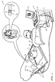
Fig. 1 is a pictorial illustration of a system for detecting electrical activity in a heart of a living subject in accordance with an embodiment of the invention; -
Fig. 2 is a schematic diagram of an electrode assembly on the shaft of a cardiac catheter in accordance with an embodiment of the invention; -
Fig. 3 is a schematic sectional view through the longitudinal axis of the distal portion of a cardiac catheter in accordance with an embodiment of the invention; -
Fig. 4 is a schematic side view of an electrode arrangement on the distal portion of a cardiac catheter in accordance with an embodiment of the invention; -
Fig. 5 is a schematic plan view of an electrode arrangement on the distal portion of a cardiac catheter in accordance with an alternate embodiment of the invention; and -
Fig. 6 - Fig. 17 are simulation examples showing the effect on the far field component of an intracardiac electrogram as the height of the guard electrodes varies from 0.2 - 10 mm. - In the following description, numerous specific details are set forth in order to provide a thorough understanding of the various principles of the present invention. It will be apparent to one skilled in the art, however, that not all these details are necessarily needed for practicing the present invention. In this instance, well-known circuits, control logic, and the details of computer program instructions for conventional algorithms and processes have not been shown in detail in order not to obscure the general concepts unnecessarily.
- Turning now to the drawings, reference is initially made to
Fig. 1 , which is a pictorial illustration of asystem 10 for evaluating electrical activity and performing ablative procedures on aheart 12 of a living subject, which is constructed and operative in accordance with a disclosed embodiment of the invention. The system comprises acatheter 14, which is percutaneously inserted by anoperator 16 through the patient's vascular system into a chamber or vascular structure of theheart 12. Theoperator 16, who is typically a physician, brings the catheter'sdistal tip 18 into contact with the heart wall, for example, at an ablation target site. Electrical activation maps may be prepared, according to the methods disclosed inU.S. Patent Nos. 6,226,542 , and6,301,496 , and in commonly assignedU.S. Patent No. 6,892,091 , whose disclosures are herein incorporated by reference. One commercial product embodying elements of thesystem 10 is available as theCARTO ® 3 System, available from Bio-sense Webster, Inc., 3333 Diamond Canyon Road, Diamond Bar, CA 91765. This system may be modified by those skilled in the art to embody the principles of the invention described herein. - Areas determined to be abnormal, for example by evaluation of the electrical activation maps, can be ablated by application of thermal energy, e.g., by passage of radiofrequency electrical current through wires in the catheter to one or more electrodes at the
distal tip 18, which apply the radiofrequency energy to the myocardium. The energy is absorbed in the tissue, heating it to a point (typically about 50°C) at which it permanently loses its electrical excitability. When successful, this procedure creates non-conducting lesions in the cardiac tissue, which disrupt the abnormal electrical pathway causing the arrhythmia. The principles of the invention can be applied to different heart chambers to diagnose and treat many different cardiac arrhythmias. - The
catheter 14 typically comprises ahandle 20, having suitable controls on the handle to enable theoperator 16 to steer, position and orient the distal end of the catheter as desired for the ablation. To aid theoperator 16, the distal portion of thecatheter 14 contains position sensors (not shown) that provide signals to aprocessor 22, located in aconsole 24. Theprocessor 22 may fulfill several processing functions as described below. - Ablation energy and electrical signals can be conveyed to and from the
heart 12 through one ormore ablation electrodes 32 located at or near thedistal tip 18 viacable 34 to theconsole 24. Pacing signals and other control signals may be conveyed from theconsole 24 through thecable 34 and theelectrodes 32 to theheart 12.Sensing electrodes 33, also connected to theconsole 24 are disposed between theablation electrodes 32 and have connections to thecable 34. -
Wire connections 35 link theconsole 24 withbody surface electrodes 30 and other components of a positioning sub-system for measuring location and orientation coordinates of thecatheter 14. Theprocessor 22 or another processor (not shown) may be an element of the positioning subsystem. Theelectrodes 32 and thebody surface electrodes 30 may be used to measure tissue impedance at the ablation site as taught inU.S. Patent No. 7,536,218, issued to Govari et al. , which is herein incorporated by reference. A temperature sensor (not shown), typically a thermocouple or thermistor, may be mounted on or near each of theelectrodes 32. - The
console 24 typically contains one or moreablation power generators 25. Thecatheter 14 may be adapted to conduct ablative energy to the heart using any known ablation technique, e.g., radiofrequency energy, ultrasound energy, and laser-produced light energy. Such methods are disclosed in commonly assignedU.S. Patent Nos. 6,814,733 ,6,997,924 , and7,156,816 , which are herein incorporated by reference. - In one embodiment, the positioning subsystem comprises a magnetic position tracking arrangement that determines the position and orientation of the
catheter 14 by generating magnetic fields in a predefined working volume and sensing these fields at the catheter, using field generating coils 28. The positioning subsystem is described inU.S. Patent No. 7,756,576 , which is hereby incorporated by reference, and in the above-notedU.S. Patent No. 7,536,218 . - As noted above, the
catheter 14 is coupled to theconsole 24, which enables theoperator 16 to observe and regulate the functions of thecatheter 14.Console 24 includes a processor, preferably a computer with appropriate signal processing circuits. The processor is coupled to drive a monitor 29. The signal processing circuits typically receive, amplify, filter and digitize signals from thecatheter 14, including signals generated by sensors such as electrical, temperature and contact force sensors, and a plurality of location sensing electrodes (not shown) located distally in thecatheter 14. The digitized signals are received and used by theconsole 24 and the positioning system to compute the position and orientation of thecatheter 14, and to analyze the electrical signals from the electrodes. - In order to generate electroanatomic maps, the
processor 22 typically comprises an electroanatomic map generator, an image registration program, an image or data analysis program and a graphical user interface configured to present graphical information on the monitor 29. - Typically, the
system 10 includes other elements, which are not shown in the figures for the sake of simplicity. For example, thesystem 10 may include an electrocardiogram (ECG) monitor, coupled to receive signals from one or more body surface electrodes, in order to provide an ECG synchronization signal to theconsole 24. As mentioned above, thesystem 10 typically also includes a reference position sensor, either on an externally-applied reference patch attached to the exterior of the subject's body, or on an internally-placed catheter, which is inserted into theheart 12 maintained in a fixed position relative to theheart 12. Conventional pumps and lines for circulating liquids through thecatheter 14 for cooling the ablation site are provided. Thesystem 10 may receive image data from an external imaging modality, such as an MRI unit or the like and includes image processors that can be incorporated in or invoked by theprocessor 22 for generating and displaying images. - Reference is now made to
Fig. 2 , which is a schematic diagram of anelectrode assembly 37 on the shaft of acardiac catheter 39 in accordance with an embodiment of the invention. Theelectrode assembly 37 comprises aunipolar sensing electrode 41 bracketed on at least two sides byguard electrodes 43. A protective effect against far field interference is represented by anarcuate zone 45 that extends between theguard electrodes 43 and overarches thesensing electrode 41. Near-field potentials are detected by thesensing electrode 41 in azone 47 immediately overlying thesensing electrode 41 and within thezone 45. Theguard electrodes 43 are grounded. Thesensing electrode 41 is connected to receiving circuitry that reads the potentials measured by thesensing electrode 41. - Reference is now made to
Fig. 3 , which is a schematic sectional view through the longitudinal axis of the distal portion of acardiac catheter 49 in accordance with an embodiment of the invention.Fig. 3 illustrates a profile of sensingelectrode 51 andguard electrodes 53. In practice thesensing electrode 51 and theguard electrodes 53 need not be raised above the surface of the catheter, but can be flush with the surface. In embodiments in which they are elevated above the surface, the elevation should be small, relative to the widths of the electrodes. Thesensing electrode 51 andguard electrodes 53 are typically less than 0.3 mm in height. The heights and thicknesses of these electrodes are not critical. - Reference is now made to
Fig. 4 , which is a schematic side view of an electrode arrangement on the distal portion of acardiac catheter 57 in accordance with an embodiment of the invention. Aunipolar ring electrode 59 used for electrophysiological mapping of cardiac conduction lies between two groundedguard electrodes 61, which are also ring electrodes. As explained above in the discussion ofFig. 2 , when the catheter is inserted into a heart and mapping is carried out, theguard electrodes 61 decrease far field signals at thering electrode 59, i.e., signals originating at distances of 2 mm or more from thering electrode 59. Theguard electrodes 61 do not influence near field signals, i.e., those originating at distances less than 2 mm from thering electrode 59. Optimum spacing between thering electrode 59 andguard electrodes 61 varies with the desired distance range between thering electrode 59 and target tissue. The interspaces are set such that signals originating from sources more remote than the desired distance range are considered as far field signals and reduced by theguard electrodes 61. In general it is suitable to adjust the gap and electrode dimensions such that the interspace is a half-width of thering electrode 59 - Reference is now made to
Fig. 5 , which is a schematic plan view of anelectrode arrangement 63 on the distal portion of acardiac catheter 65 in accordance with an alternate embodiment of the invention. Aplate electrode 67 is connected to receiving circuitry. Theelectrode 67 is used for obtaining electrograms, e.g., for mapping purposes. Theelectrode 67 is encircled byguard electrode 69, which is connected to ground, as shown inFig. 2 . Theelectrode 67 andguard electrode 69 are spaced apart by agap 71, which is typically 1 - 2 mm in width. Thecardiac catheter 65 may include any number of instances of theelectrode arrangement 63. -
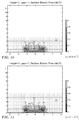
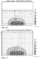
Fig. 6 ,Fig. 7, Fig. 8, Fig. 9 ,Fig. 10, Fig. 11 ,Fig. 12, Fig. 13 ,Fig. 14, Fig. 15 ,Fig. 16 and Fig. 17 are simulation examples showing the effect on the far field component of an intracardiac electrogram.as the height of the guard electrodes varies from 0.2 - 10 mm. In these simulations aplate 73 is the source of an electric field. Instances of agap 75 that separates sensingelectrode 77 andguard electrodes 79 are occur at 0.5 mm and 1 mm. Electrical field strength is indicated by the keys on a scale at the right of the drawing figures. The variation in the patterns illustrate the shielding effect of theguard electrodes 79. The field intensity of theplate 73 has a maximum intensity of 1. Theguard electrodes 79, which are grounded, experience a minimum field intensity, - In the figures, especially
Fig. 6 , in which theplate 73 is close to thesensing electrode 77, theplate 73 acts as a near field source, and thesensing electrode 77 experiences a relatively high field intensity. The field intensity to which thesensing electrode 77 is exposed progressively diminishes in the examples ofFig. 7 - Fig. 12 as adistance 81 between theplate 73 and thesensing electrode 77 increases. Thegap 75 between the sensingelectrode 77 andguard electrodes 79 is optimally electrode half-width, i.e., half the width of thesensing electrode 77. A larger gap tends to decrease the screening effect, while a smaller gap decreases the signal of thesensing electrode 77. - The value scale at the right of the figures represents the relative strength of the electric field. The drawing figures illustrate the shielding effect of the guard electrode. The source of the field is the
plate 73 in the upper portion of the figures. Its potential is the highest and is equal to 1 in the relative value scale. When theupper plate 73 is close to thesensing electrode 77, it acts as a near field source and thesensing electrode 77 experiences a high field value, i.e., it receives the full field strength of theplate 73. As thedistance 81 between theplate 73 and thesensing electrode 77 increases, the field produced by theplate 73 increasingly simulates the characteristics of a far field source. The voltage received by the receiving electrode decreases and the electrode field strength at thesensing electrode 77 decreases accordingly. The dimensions of thesensing electrode 77 theguard electrodes 79 and thegap 75 all influence the field strength experienced by thesensing electrode 77. - The following configuration was used in the simulation examples: Plate receiving electrode (radius rplate=1mm), guard ring electrode (ring=1.4-2.5mm, ring width=0.3mm). Guard ring electrode grounded.
- It will be appreciated by persons skilled in the art that the present invention is not limited to what has been particularly shown and described hereinabove. Rather, the scope of the present invention includes both combinations and sub-combinations of the various features described hereinabove, as well as variations and modifications thereof that are not in the prior art, which would occur to persons skilled in the art upon reading the foregoing description.
- Aspects of the invention:
- 1. A method comprising the steps of:
- inserting into a heart of a living subject a catheter having an elongated distal portion, an electrode assembly disposed on the distal portion, the electrode assembly comprising a unipolar sensing electrode connected to a receiver and at least one grounded guard electrode spaced apart from the sensing electrode by a gap, the sensing electrode being bracketed on at least two sides by the at least one grounded guard electrode; and
- receiving signals from the sensing electrode in the receiver.
- 2. The method according to
aspect 1, wherein the sensing electrode has a width dimension, and the gap is one-half the width dimension. - 3. The method according to
aspect 1, wherein the distal portion of the catheter has a circumference, and wherein the sensing electrode and the at least one grounded guard electrode are ring electrodes that encircle the circumference of the catheter. - 4. The method according to
aspect 1, wherein the catheter has an external surface, and the sensing electrode and the at least one grounded guard electrode are elevated above the external surface. - 5. The method according to
aspect 4, wherein the sensing electrode and the at least one grounded guard electrode have respective width dimensions, wherein elevations of the sensing electrode and the at least one grounded guard electrode are less than the respective width dimensions. - 6. The method according to
aspect 1, wherein the catheter has an external surface, and the sensing electrode and the at least one grounded guard electrode are flush with the external surface. - 7. The method according to
aspect 6, wherein the sensing electrode and the at least one grounded guard electrode have respective width dimensions, wherein elevations of the sensing electrode and the at least one grounded guard electrode are less than the respective width dimensions. - 8. The method according to
aspect 1, wherein the at least one grounded guard electrode is a single electrode that surrounds the sensing electrode.
Claims (8)
- An apparatus comprising
a catheter having an elongated distal portion;
an electrode assembly disposed on the distal portion and comprising:a sensing electrode connected to a receiver; andat least one grounded guard electrode spaced apart from the sensing electrode by a gap, the sensing electrode being bracketed on at least two sides by the at least one grounded guard electrode. - The apparatus according to claim 1, wherein the sensing electrode has a width dimension, and the gap is one-half the width dimension.
- The apparatus according to claim 1, wherein the distal portion of the catheter has a circumference, and wherein the sensing electrode and the at least one grounded guard electrode are ring electrodes that encircle the circumference of the catheter.
- The apparatus according to claim 1, wherein the catheter has an external surface, and the sensing electrode and the at least one grounded guard electrode are elevated above the external surface.
- The apparatus according to claim 4, wherein the sensing electrode and the at least one grounded guard electrode have respective width dimensions, wherein elevations of the sensing electrode and the at least one grounded guard electrode are less than the respective width dimensions.
- The apparatus according to claim 1, wherein the catheter has an external surface, and the sensing electrode and the at least one grounded guard electrode are flush with the external surface.
- The apparatus according to claim 6, wherein the sensing electrode and the at least one grounded guard electrode have respective width dimensions, wherein elevations of the sensing electrode and the at least one grounded guard electrode are less than the respective width dimensions.
- The apparatus according to claim 1, wherein the at least one grounded guard electrode is a single electrode that surrounds the sensing electrode.
Applications Claiming Priority (2)
| Application Number | Priority Date | Filing Date | Title |
|---|---|---|---|
| US201462093773P | 2014-12-18 | 2014-12-18 | |
| US14/929,990 US20160174864A1 (en) | 2014-12-18 | 2015-11-02 | Far Field-Insensitive Intracardiac Catheter Electrodes |
Publications (2)
| Publication Number | Publication Date |
|---|---|
| EP3033995A1 true EP3033995A1 (en) | 2016-06-22 |
| EP3033995B1 EP3033995B1 (en) | 2019-06-05 |
Family
ID=55069686
Family Applications (1)
| Application Number | Title | Priority Date | Filing Date |
|---|---|---|---|
| EP15200942.9A Active EP3033995B1 (en) | 2014-12-18 | 2015-12-17 | Far field-insensitive intracardiac catheter electrodes |
Country Status (8)
| Country | Link |
|---|---|
| US (1) | US20160174864A1 (en) |
| EP (1) | EP3033995B1 (en) |
| JP (1) | JP6752571B2 (en) |
| CN (1) | CN105708449A (en) |
| AU (1) | AU2015271949A1 (en) |
| CA (1) | CA2915287A1 (en) |
| ES (1) | ES2739664T3 (en) |
| IL (1) | IL243044B (en) |
Families Citing this family (12)
| Publication number | Priority date | Publication date | Assignee | Title |
|---|---|---|---|---|
| WO2008070189A2 (en) | 2006-12-06 | 2008-06-12 | The Cleveland Clinic Foundation | Method and system for treating acute heart failure by neuromodulation |
| WO2015179634A2 (en) | 2014-05-22 | 2015-11-26 | CARDIONOMIC, Inc. | Catheter and catheter system for electrical neuromodulation |
| EP3194017A1 (en) | 2014-09-08 | 2017-07-26 | Cardionomic, Inc. | Methods for electrical neuromodulation of the heart |
| AU2015315658B2 (en) | 2014-09-08 | 2019-05-23 | CARDIONOMIC, Inc. | Catheter and electrode systems for electrical neuromodulation |
| EP3242717B1 (en) | 2015-01-05 | 2019-06-12 | Cardionomic, Inc. | Cardiac modulation facilitation systems |
| EP3426338A4 (en) | 2016-03-09 | 2019-10-30 | Cardionomic, Inc. | Cardiac contractility neurostimulation systems and methods |
| US10932850B2 (en) | 2016-05-02 | 2021-03-02 | Affera, Inc. | Lesion formation |
| EP3664703A4 (en) | 2017-09-13 | 2021-05-12 | Cardionomic, Inc. | Neurostimulation systems and methods for affecting cardiac contractility |
| CA3107959A1 (en) | 2018-08-13 | 2020-02-20 | CARDIONOMIC, Inc. | Systems and methods for affecting cardiac contractility and/or relaxation |
| US11464437B2 (en) * | 2019-03-06 | 2022-10-11 | Biosense Webster (Israel) Ltd. | Mid-field signal extraction |
| CA3137307A1 (en) | 2019-05-06 | 2020-11-12 | CARDIONOMIC, Inc. | Systems and methods for denoising physiological signals during electrical neuromodulation |
| USD1014762S1 (en) | 2021-06-16 | 2024-02-13 | Affera, Inc. | Catheter tip with electrode panel(s) |
Citations (17)
| Publication number | Priority date | Publication date | Assignee | Title |
|---|---|---|---|---|
| WO1996005768A1 (en) | 1994-08-19 | 1996-02-29 | Biosense, Inc. | Medical diagnosis, treatment and imaging systems |
| US5546951A (en) | 1993-07-20 | 1996-08-20 | Biosense, Inc. | Method and apparatus for studying cardiac arrhythmias |
| US5738096A (en) | 1993-07-20 | 1998-04-14 | Biosense, Inc. | Cardiac electromechanics |
| WO2000057947A2 (en) * | 1999-03-30 | 2000-10-05 | Impulse Dynamics N.V. | Bipolar sensor for muscle tissue action potential duration estimation |
| US6226542B1 (en) | 1998-07-24 | 2001-05-01 | Biosense, Inc. | Three-dimensional reconstruction of intrabody organs |
| US6301496B1 (en) | 1998-07-24 | 2001-10-09 | Biosense, Inc. | Vector mapping of three-dimensionally reconstructed intrabody organs and method of display |
| US6690963B2 (en) | 1995-01-24 | 2004-02-10 | Biosense, Inc. | System for determining the location and orientation of an invasive medical instrument |
| US6814733B2 (en) | 2002-01-31 | 2004-11-09 | Biosense, Inc. | Radio frequency pulmonary vein isolation |
| US6892091B1 (en) | 2000-02-18 | 2005-05-10 | Biosense, Inc. | Catheter, method and apparatus for generating an electrical map of a chamber of the heart |
| US6997924B2 (en) | 2002-09-17 | 2006-02-14 | Biosense Inc. | Laser pulmonary vein isolation |
| US7156816B2 (en) | 2002-11-26 | 2007-01-02 | Biosense, Inc. | Ultrasound pulmonary vein isolation |
| US7536218B2 (en) | 2005-07-15 | 2009-05-19 | Biosense Webster, Inc. | Hybrid magnetic-based and impedance-based position sensing |
| US7756576B2 (en) | 2005-08-26 | 2010-07-13 | Biosense Webster, Inc. | Position sensing and detection of skin impedance |
| US20140005664A1 (en) | 2012-07-02 | 2014-01-02 | Assaf Govari | Real time assessment of ablation from electrocardiogram signals |
| WO2014047068A1 (en) * | 2012-09-18 | 2014-03-27 | Boston Scientific Scimed, Inc. | Map and ablate closed-loop cooled ablation catheter |
| WO2014085405A1 (en) * | 2012-11-29 | 2014-06-05 | Albert Einstein Healthcare Network | Catheter systems for measuring electrical properties of tissue |
| US20140187991A1 (en) | 2012-12-27 | 2014-07-03 | Boston Scientific Scimed, Inc. | Artifact cancellation to suppress far-field activation during electrophysiology mapping |
Family Cites Families (9)
| Publication number | Priority date | Publication date | Assignee | Title |
|---|---|---|---|---|
| DE3623711A1 (en) * | 1985-07-12 | 1987-01-15 | Med & Tech Handels Gmbh | Device for the determination of properties, variations and changes of the human or animal body |
| US5156151A (en) * | 1991-02-15 | 1992-10-20 | Cardiac Pathways Corporation | Endocardial mapping and ablation system and catheter probe |
| US6259938B1 (en) * | 1998-05-15 | 2001-07-10 | Respironics, Inc. | Monitoring catheter and method of using same |
| KR100459903B1 (en) * | 2002-07-25 | 2004-12-03 | 삼성전자주식회사 | Measurement system and electrode for measuring the impedance of small area of skin |
| US20060025666A1 (en) * | 2004-06-10 | 2006-02-02 | Kinesense, Inc. | "Bulls-eye" surface electromyographic electrode assembly |
| US20080300587A1 (en) * | 2005-03-02 | 2008-12-04 | Cathrx Ltd | Heat Treatment Catheter |
| WO2010056438A2 (en) * | 2008-11-13 | 2010-05-20 | Proteus Biomedical, Inc. | Shielded stimulation and sensing system and method |
| US8712550B2 (en) * | 2008-12-30 | 2014-04-29 | Biosense Webster, Inc. | Catheter with multiple electrode assemblies for use at or near tubular regions of the heart |
| EP2840964B1 (en) * | 2012-04-27 | 2019-04-17 | Fibrux Oy | A method and a device for measuring muscle signals |
-
2015
- 2015-11-02 US US14/929,990 patent/US20160174864A1/en not_active Abandoned
- 2015-12-10 IL IL243044A patent/IL243044B/en active IP Right Grant
- 2015-12-14 CA CA2915287A patent/CA2915287A1/en not_active Abandoned
- 2015-12-17 ES ES15200942T patent/ES2739664T3/en active Active
- 2015-12-17 JP JP2015246064A patent/JP6752571B2/en active Active
- 2015-12-17 EP EP15200942.9A patent/EP3033995B1/en active Active
- 2015-12-18 CN CN201510957769.7A patent/CN105708449A/en active Pending
- 2015-12-18 AU AU2015271949A patent/AU2015271949A1/en not_active Abandoned
Patent Citations (17)
| Publication number | Priority date | Publication date | Assignee | Title |
|---|---|---|---|---|
| US5546951A (en) | 1993-07-20 | 1996-08-20 | Biosense, Inc. | Method and apparatus for studying cardiac arrhythmias |
| US5738096A (en) | 1993-07-20 | 1998-04-14 | Biosense, Inc. | Cardiac electromechanics |
| WO1996005768A1 (en) | 1994-08-19 | 1996-02-29 | Biosense, Inc. | Medical diagnosis, treatment and imaging systems |
| US6690963B2 (en) | 1995-01-24 | 2004-02-10 | Biosense, Inc. | System for determining the location and orientation of an invasive medical instrument |
| US6226542B1 (en) | 1998-07-24 | 2001-05-01 | Biosense, Inc. | Three-dimensional reconstruction of intrabody organs |
| US6301496B1 (en) | 1998-07-24 | 2001-10-09 | Biosense, Inc. | Vector mapping of three-dimensionally reconstructed intrabody organs and method of display |
| WO2000057947A2 (en) * | 1999-03-30 | 2000-10-05 | Impulse Dynamics N.V. | Bipolar sensor for muscle tissue action potential duration estimation |
| US6892091B1 (en) | 2000-02-18 | 2005-05-10 | Biosense, Inc. | Catheter, method and apparatus for generating an electrical map of a chamber of the heart |
| US6814733B2 (en) | 2002-01-31 | 2004-11-09 | Biosense, Inc. | Radio frequency pulmonary vein isolation |
| US6997924B2 (en) | 2002-09-17 | 2006-02-14 | Biosense Inc. | Laser pulmonary vein isolation |
| US7156816B2 (en) | 2002-11-26 | 2007-01-02 | Biosense, Inc. | Ultrasound pulmonary vein isolation |
| US7536218B2 (en) | 2005-07-15 | 2009-05-19 | Biosense Webster, Inc. | Hybrid magnetic-based and impedance-based position sensing |
| US7756576B2 (en) | 2005-08-26 | 2010-07-13 | Biosense Webster, Inc. | Position sensing and detection of skin impedance |
| US20140005664A1 (en) | 2012-07-02 | 2014-01-02 | Assaf Govari | Real time assessment of ablation from electrocardiogram signals |
| WO2014047068A1 (en) * | 2012-09-18 | 2014-03-27 | Boston Scientific Scimed, Inc. | Map and ablate closed-loop cooled ablation catheter |
| WO2014085405A1 (en) * | 2012-11-29 | 2014-06-05 | Albert Einstein Healthcare Network | Catheter systems for measuring electrical properties of tissue |
| US20140187991A1 (en) | 2012-12-27 | 2014-07-03 | Boston Scientific Scimed, Inc. | Artifact cancellation to suppress far-field activation during electrophysiology mapping |
Also Published As
| Publication number | Publication date |
|---|---|
| EP3033995B1 (en) | 2019-06-05 |
| JP2016116858A (en) | 2016-06-30 |
| CA2915287A1 (en) | 2016-06-18 |
| CN105708449A (en) | 2016-06-29 |
| IL243044B (en) | 2019-09-26 |
| ES2739664T3 (en) | 2020-02-03 |
| US20160174864A1 (en) | 2016-06-23 |
| JP6752571B2 (en) | 2020-09-09 |
| AU2015271949A1 (en) | 2016-07-07 |
| IL243044A0 (en) | 2016-02-29 |
Similar Documents
| Publication | Publication Date | Title |
|---|---|---|
| EP3033995B1 (en) | Far field-insensitive intracardiac catheter electrodes | |
| JP6517277B2 (en) | Real-time feedback of electrode contacts during mapping | |
| US11278228B2 (en) | Identification and visualization of cardiac activation sequence in multi-channel recordings | |
| US10441188B2 (en) | Automatic display of earliest LAT point | |
| US8577450B1 (en) | Graphic interface for multi-spine probe | |
| EP2848191A1 (en) | Device for mapping ventricular/atrial premature beats during sinus rhythm | |
| EP2229904A1 (en) | Dual-purpose lasso catheter with irrigation | |
| JP2018140171A (en) | Highlighting electrode image according to electrode signal | |
| EP3181046B1 (en) | Sheath visualization method by means of impedance localization and magnetic information | |
| US11207125B2 (en) | Effective parasitic capacitance minimization for micro ablation electrode | |
| JP2007185516A (en) | Mapping of complex fractionated atrial electrogram | |
| EP2870939A1 (en) | Using catheter position and temperature measurement to detect movement from ablation point | |
| US9706937B2 (en) | Ventricular electrical activity indicator | |
| US11464437B2 (en) | Mid-field signal extraction | |
| US20200397329A1 (en) | Methods and systems for transmural tissue mapping |
Legal Events
| Date | Code | Title | Description |
|---|---|---|---|
| PUAI | Public reference made under article 153(3) epc to a published international application that has entered the european phase |
Free format text: ORIGINAL CODE: 0009012 |
|
| AK | Designated contracting states |
Kind code of ref document: A1 Designated state(s): AL AT BE BG CH CY CZ DE DK EE ES FI FR GB GR HR HU IE IS IT LI LT LU LV MC MK MT NL NO PL PT RO RS SE SI SK SM TR |
|
| AX | Request for extension of the european patent |
Extension state: BA ME |
|
| STAA | Information on the status of an ep patent application or granted ep patent |
Free format text: STATUS: REQUEST FOR EXAMINATION WAS MADE |
|
| 17P | Request for examination filed |
Effective date: 20161220 |
|
| RBV | Designated contracting states (corrected) |
Designated state(s): AL AT BE BG CH CY CZ DE DK EE ES FI FR GB GR HR HU IE IS IT LI LT LU LV MC MK MT NL NO PL PT RO RS SE SI SK SM TR |
|
| GRAP | Despatch of communication of intention to grant a patent |
Free format text: ORIGINAL CODE: EPIDOSNIGR1 |
|
| STAA | Information on the status of an ep patent application or granted ep patent |
Free format text: STATUS: GRANT OF PATENT IS INTENDED |
|
| INTG | Intention to grant announced |
Effective date: 20190109 |
|
| GRAS | Grant fee paid |
Free format text: ORIGINAL CODE: EPIDOSNIGR3 |
|
| GRAA | (expected) grant |
Free format text: ORIGINAL CODE: 0009210 |
|
| STAA | Information on the status of an ep patent application or granted ep patent |
Free format text: STATUS: THE PATENT HAS BEEN GRANTED |
|
| AK | Designated contracting states |
Kind code of ref document: B1 Designated state(s): AL AT BE BG CH CY CZ DE DK EE ES FI FR GB GR HR HU IE IS IT LI LT LU LV MC MK MT NL NO PL PT RO RS SE SI SK SM TR |
|
| REG | Reference to a national code |
Ref country code: GB Ref legal event code: FG4D |
|
| REG | Reference to a national code |
Ref country code: CH Ref legal event code: EP |
|
| REG | Reference to a national code |
Ref country code: AT Ref legal event code: REF Ref document number: 1139182 Country of ref document: AT Kind code of ref document: T Effective date: 20190615 |
|
| REG | Reference to a national code |
Ref country code: IE Ref legal event code: FG4D |
|
| REG | Reference to a national code |
Ref country code: DE Ref legal event code: R096 Ref document number: 602015031324 Country of ref document: DE |
|
| REG | Reference to a national code |
Ref country code: NL Ref legal event code: FP |
|
| REG | Reference to a national code |
Ref country code: LT Ref legal event code: MG4D |
|
| PG25 | Lapsed in a contracting state [announced via postgrant information from national office to epo] |
Ref country code: SE Free format text: LAPSE BECAUSE OF FAILURE TO SUBMIT A TRANSLATION OF THE DESCRIPTION OR TO PAY THE FEE WITHIN THE PRESCRIBED TIME-LIMIT Effective date: 20190605 Ref country code: AL Free format text: LAPSE BECAUSE OF FAILURE TO SUBMIT A TRANSLATION OF THE DESCRIPTION OR TO PAY THE FEE WITHIN THE PRESCRIBED TIME-LIMIT Effective date: 20190605 Ref country code: LT Free format text: LAPSE BECAUSE OF FAILURE TO SUBMIT A TRANSLATION OF THE DESCRIPTION OR TO PAY THE FEE WITHIN THE PRESCRIBED TIME-LIMIT Effective date: 20190605 Ref country code: HR Free format text: LAPSE BECAUSE OF FAILURE TO SUBMIT A TRANSLATION OF THE DESCRIPTION OR TO PAY THE FEE WITHIN THE PRESCRIBED TIME-LIMIT Effective date: 20190605 Ref country code: NO Free format text: LAPSE BECAUSE OF FAILURE TO SUBMIT A TRANSLATION OF THE DESCRIPTION OR TO PAY THE FEE WITHIN THE PRESCRIBED TIME-LIMIT Effective date: 20190905 Ref country code: FI Free format text: LAPSE BECAUSE OF FAILURE TO SUBMIT A TRANSLATION OF THE DESCRIPTION OR TO PAY THE FEE WITHIN THE PRESCRIBED TIME-LIMIT Effective date: 20190605 |
|
| PG25 | Lapsed in a contracting state [announced via postgrant information from national office to epo] |
Ref country code: RS Free format text: LAPSE BECAUSE OF FAILURE TO SUBMIT A TRANSLATION OF THE DESCRIPTION OR TO PAY THE FEE WITHIN THE PRESCRIBED TIME-LIMIT Effective date: 20190605 Ref country code: LV Free format text: LAPSE BECAUSE OF FAILURE TO SUBMIT A TRANSLATION OF THE DESCRIPTION OR TO PAY THE FEE WITHIN THE PRESCRIBED TIME-LIMIT Effective date: 20190605 Ref country code: GR Free format text: LAPSE BECAUSE OF FAILURE TO SUBMIT A TRANSLATION OF THE DESCRIPTION OR TO PAY THE FEE WITHIN THE PRESCRIBED TIME-LIMIT Effective date: 20190906 Ref country code: BG Free format text: LAPSE BECAUSE OF FAILURE TO SUBMIT A TRANSLATION OF THE DESCRIPTION OR TO PAY THE FEE WITHIN THE PRESCRIBED TIME-LIMIT Effective date: 20190905 |
|
| REG | Reference to a national code |
Ref country code: AT Ref legal event code: MK05 Ref document number: 1139182 Country of ref document: AT Kind code of ref document: T Effective date: 20190605 |
|
| PG25 | Lapsed in a contracting state [announced via postgrant information from national office to epo] |
Ref country code: EE Free format text: LAPSE BECAUSE OF FAILURE TO SUBMIT A TRANSLATION OF THE DESCRIPTION OR TO PAY THE FEE WITHIN THE PRESCRIBED TIME-LIMIT Effective date: 20190605 Ref country code: AT Free format text: LAPSE BECAUSE OF FAILURE TO SUBMIT A TRANSLATION OF THE DESCRIPTION OR TO PAY THE FEE WITHIN THE PRESCRIBED TIME-LIMIT Effective date: 20190605 Ref country code: RO Free format text: LAPSE BECAUSE OF FAILURE TO SUBMIT A TRANSLATION OF THE DESCRIPTION OR TO PAY THE FEE WITHIN THE PRESCRIBED TIME-LIMIT Effective date: 20190605 Ref country code: CZ Free format text: LAPSE BECAUSE OF FAILURE TO SUBMIT A TRANSLATION OF THE DESCRIPTION OR TO PAY THE FEE WITHIN THE PRESCRIBED TIME-LIMIT Effective date: 20190605 Ref country code: PT Free format text: LAPSE BECAUSE OF FAILURE TO SUBMIT A TRANSLATION OF THE DESCRIPTION OR TO PAY THE FEE WITHIN THE PRESCRIBED TIME-LIMIT Effective date: 20191007 Ref country code: SK Free format text: LAPSE BECAUSE OF FAILURE TO SUBMIT A TRANSLATION OF THE DESCRIPTION OR TO PAY THE FEE WITHIN THE PRESCRIBED TIME-LIMIT Effective date: 20190605 |
|
| REG | Reference to a national code |
Ref country code: ES Ref legal event code: FG2A Ref document number: 2739664 Country of ref document: ES Kind code of ref document: T3 Effective date: 20200203 |
|
| PG25 | Lapsed in a contracting state [announced via postgrant information from national office to epo] |
Ref country code: IS Free format text: LAPSE BECAUSE OF FAILURE TO SUBMIT A TRANSLATION OF THE DESCRIPTION OR TO PAY THE FEE WITHIN THE PRESCRIBED TIME-LIMIT Effective date: 20191005 Ref country code: SM Free format text: LAPSE BECAUSE OF FAILURE TO SUBMIT A TRANSLATION OF THE DESCRIPTION OR TO PAY THE FEE WITHIN THE PRESCRIBED TIME-LIMIT Effective date: 20190605 |
|
| PGFP | Annual fee paid to national office [announced via postgrant information from national office to epo] |
Ref country code: BE Payment date: 20191118 Year of fee payment: 5 |
|
| REG | Reference to a national code |
Ref country code: DE Ref legal event code: R097 Ref document number: 602015031324 Country of ref document: DE |
|
| PG25 | Lapsed in a contracting state [announced via postgrant information from national office to epo] |
Ref country code: TR Free format text: LAPSE BECAUSE OF FAILURE TO SUBMIT A TRANSLATION OF THE DESCRIPTION OR TO PAY THE FEE WITHIN THE PRESCRIBED TIME-LIMIT Effective date: 20190605 |
|
| PLBE | No opposition filed within time limit |
Free format text: ORIGINAL CODE: 0009261 |
|
| STAA | Information on the status of an ep patent application or granted ep patent |
Free format text: STATUS: NO OPPOSITION FILED WITHIN TIME LIMIT |
|
| PG25 | Lapsed in a contracting state [announced via postgrant information from national office to epo] |
Ref country code: DK Free format text: LAPSE BECAUSE OF FAILURE TO SUBMIT A TRANSLATION OF THE DESCRIPTION OR TO PAY THE FEE WITHIN THE PRESCRIBED TIME-LIMIT Effective date: 20190605 Ref country code: PL Free format text: LAPSE BECAUSE OF FAILURE TO SUBMIT A TRANSLATION OF THE DESCRIPTION OR TO PAY THE FEE WITHIN THE PRESCRIBED TIME-LIMIT Effective date: 20190605 |
|
| 26N | No opposition filed |
Effective date: 20200306 |
|
| PG25 | Lapsed in a contracting state [announced via postgrant information from national office to epo] |
Ref country code: SI Free format text: LAPSE BECAUSE OF FAILURE TO SUBMIT A TRANSLATION OF THE DESCRIPTION OR TO PAY THE FEE WITHIN THE PRESCRIBED TIME-LIMIT Effective date: 20190605 |
|
| REG | Reference to a national code |
Ref country code: CH Ref legal event code: PL |
|
| PG25 | Lapsed in a contracting state [announced via postgrant information from national office to epo] |
Ref country code: MC Free format text: LAPSE BECAUSE OF FAILURE TO SUBMIT A TRANSLATION OF THE DESCRIPTION OR TO PAY THE FEE WITHIN THE PRESCRIBED TIME-LIMIT Effective date: 20190605 |
|
| PG25 | Lapsed in a contracting state [announced via postgrant information from national office to epo] |
Ref country code: LU Free format text: LAPSE BECAUSE OF NON-PAYMENT OF DUE FEES Effective date: 20191217 Ref country code: IE Free format text: LAPSE BECAUSE OF NON-PAYMENT OF DUE FEES Effective date: 20191217 |
|
| REG | Reference to a national code |
Ref country code: DE Ref legal event code: R079 Ref document number: 602015031324 Country of ref document: DE Free format text: PREVIOUS MAIN CLASS: A61B0005042000 Ipc: A61B0005283000 |
|
| PG25 | Lapsed in a contracting state [announced via postgrant information from national office to epo] |
Ref country code: LI Free format text: LAPSE BECAUSE OF NON-PAYMENT OF DUE FEES Effective date: 20191231 Ref country code: CH Free format text: LAPSE BECAUSE OF NON-PAYMENT OF DUE FEES Effective date: 20191231 |
|
| REG | Reference to a national code |
Ref country code: ES Ref legal event code: FD2A Effective date: 20210524 |
|
| PG25 | Lapsed in a contracting state [announced via postgrant information from national office to epo] |
Ref country code: CY Free format text: LAPSE BECAUSE OF FAILURE TO SUBMIT A TRANSLATION OF THE DESCRIPTION OR TO PAY THE FEE WITHIN THE PRESCRIBED TIME-LIMIT Effective date: 20190605 |
|
| PG25 | Lapsed in a contracting state [announced via postgrant information from national office to epo] |
Ref country code: HU Free format text: LAPSE BECAUSE OF FAILURE TO SUBMIT A TRANSLATION OF THE DESCRIPTION OR TO PAY THE FEE WITHIN THE PRESCRIBED TIME-LIMIT; INVALID AB INITIO Effective date: 20151217 Ref country code: MT Free format text: LAPSE BECAUSE OF FAILURE TO SUBMIT A TRANSLATION OF THE DESCRIPTION OR TO PAY THE FEE WITHIN THE PRESCRIBED TIME-LIMIT Effective date: 20190605 |
|
| PG25 | Lapsed in a contracting state [announced via postgrant information from national office to epo] |
Ref country code: ES Free format text: LAPSE BECAUSE OF NON-PAYMENT OF DUE FEES Effective date: 20191218 |
|
| REG | Reference to a national code |
Ref country code: BE Ref legal event code: MM Effective date: 20201231 |
|
| PG25 | Lapsed in a contracting state [announced via postgrant information from national office to epo] |
Ref country code: MK Free format text: LAPSE BECAUSE OF FAILURE TO SUBMIT A TRANSLATION OF THE DESCRIPTION OR TO PAY THE FEE WITHIN THE PRESCRIBED TIME-LIMIT Effective date: 20190605 |
|
| PG25 | Lapsed in a contracting state [announced via postgrant information from national office to epo] |
Ref country code: BE Free format text: LAPSE BECAUSE OF NON-PAYMENT OF DUE FEES Effective date: 20201231 |
|
| PGFP | Annual fee paid to national office [announced via postgrant information from national office to epo] |
Ref country code: NL Payment date: 20221114 Year of fee payment: 8 |
|
| PGFP | Annual fee paid to national office [announced via postgrant information from national office to epo] |
Ref country code: GB Payment date: 20231102 Year of fee payment: 9 |
|
| PGFP | Annual fee paid to national office [announced via postgrant information from national office to epo] |
Ref country code: IT Payment date: 20231110 Year of fee payment: 9 Ref country code: FR Payment date: 20231108 Year of fee payment: 9 Ref country code: DE Payment date: 20231031 Year of fee payment: 9 |