EP3012920A1 - Electric socket - Google Patents
Electric socket Download PDFInfo
- Publication number
- EP3012920A1 EP3012920A1 EP15187500.2A EP15187500A EP3012920A1 EP 3012920 A1 EP3012920 A1 EP 3012920A1 EP 15187500 A EP15187500 A EP 15187500A EP 3012920 A1 EP3012920 A1 EP 3012920A1
- Authority
- EP
- European Patent Office
- Prior art keywords
- plug
- cover
- pawl
- locking
- button
- Prior art date
- Legal status (The legal status is an assumption and is not a legal conclusion. Google has not performed a legal analysis and makes no representation as to the accuracy of the status listed.)
- Granted
Links
- 238000003780 insertion Methods 0.000 claims description 22
- 230000037431 insertion Effects 0.000 claims description 22
- 239000000523 sample Substances 0.000 description 8
- 230000013011 mating Effects 0.000 description 6
- 230000001681 protective effect Effects 0.000 description 6
- 238000011161 development Methods 0.000 description 4
- 230000018109 developmental process Effects 0.000 description 4
- 238000006073 displacement reaction Methods 0.000 description 4
- 230000000694 effects Effects 0.000 description 4
- 238000010276 construction Methods 0.000 description 2
- 238000000034 method Methods 0.000 description 2
- 238000012546 transfer Methods 0.000 description 2
- 238000013519 translation Methods 0.000 description 2
- 238000013459 approach Methods 0.000 description 1
- 238000005452 bending Methods 0.000 description 1
- 238000013461 design Methods 0.000 description 1
- 230000005489 elastic deformation Effects 0.000 description 1
- 210000003746 feather Anatomy 0.000 description 1
- 230000003993 interaction Effects 0.000 description 1
- 239000000463 material Substances 0.000 description 1
Images


Classifications
-
- H—ELECTRICITY
- H01—ELECTRIC ELEMENTS
- H01R—ELECTRICALLY-CONDUCTIVE CONNECTIONS; STRUCTURAL ASSOCIATIONS OF A PLURALITY OF MUTUALLY-INSULATED ELECTRICAL CONNECTING ELEMENTS; COUPLING DEVICES; CURRENT COLLECTORS
- H01R13/00—Details of coupling devices of the kinds covered by groups H01R12/70 or H01R24/00 - H01R33/00
- H01R13/44—Means for preventing access to live contacts
- H01R13/447—Shutter or cover plate
- H01R13/453—Shutter or cover plate opened by engagement of counterpart
- H01R13/4534—Laterally sliding shutter
-
- H—ELECTRICITY
- H01—ELECTRIC ELEMENTS
- H01R—ELECTRICALLY-CONDUCTIVE CONNECTIONS; STRUCTURAL ASSOCIATIONS OF A PLURALITY OF MUTUALLY-INSULATED ELECTRICAL CONNECTING ELEMENTS; COUPLING DEVICES; CURRENT COLLECTORS
- H01R13/00—Details of coupling devices of the kinds covered by groups H01R12/70 or H01R24/00 - H01R33/00
- H01R13/62—Means for facilitating engagement or disengagement of coupling parts or for holding them in engagement
- H01R13/639—Additional means for holding or locking coupling parts together, after engagement, e.g. separate keylock, retainer strap
- H01R13/6397—Additional means for holding or locking coupling parts together, after engagement, e.g. separate keylock, retainer strap with means for preventing unauthorised use
Landscapes
- Details Of Connecting Devices For Male And Female Coupling (AREA)
- Connector Housings Or Holding Contact Members (AREA)
Abstract
Die Erfindung betrifft eine elektrische Steckdose, insbesondere Ladedose, zur elektrischen Steckverbindung mit einem Stecker (2), mit einem Dosengehäuse (3), einem in dem Dosengehäuse 83) angeordneten Lastkontakt (7) und einer Abdeckeinrichtung (8), wobei die Abdeckeinrichtung (8) ein Abdeckelement (9) zum steckseitigen Abdecken des Lastkontaktes (7) bei nicht eingestecktem Stecker (2) aufweist, indem das Abdeckelement (9) zwischen einer Abdeckstellung und einer Öffnungsstellung bewegbar ist, wobei das Abdeckelement (9) in der Abdeckstellung den Lastkontakt (7) steckseitig abdeckt und in der Öffnungsstellung einen steckseitigen Zugang zu dem Lastkontakt (7) bereitstellt. Erfindungsgemäß ist vorgesehen, dass die Abdeckeinrichtung (8) ein Verriegelungselement (10) aufweist, das mit einem Taster (11) und einer Klinke (12) versehen ist, wobei der Taster (11) derart angeordnet ist, dass er von der Steckseite der Steckdose her kraftbeaufschlagbar ist, die Klinke (12) zwischen einer Verriegelungsstellung und einer Entriegelungsstellung bewegbar ist, die Klinke (12) in der Verriegelungsstellung in eine Verriegelungsöffnung eingreift, die Klinke (12) in der Entriegelungsstellung aus der Verriegelungsöffnung herausgeführt ist und der Taster (11) derart mit der Klinke (12) verbunden ist, dass mittels einer steckseitigen Kraftbeaufschlagung des Tasters (11) die Klinke (12) von der Verriegelungsstellung in die Entriegelungsstellung überführbar ist. Damit wird eine elektrische Steckdose (1) die auf einfache und verlässliche Weise ein Abdecken eines gegebenenfalls spannungsführenden Kontaktes im ungesteckten Zustand ermöglicht.The invention relates to an electrical socket, in particular a socket, for electrical plug connection with a plug (2), with a socket housing (3), a in the socket housing 83 arranged load contact (7) and a covering device (8), wherein the covering device (8 ) has a cover (9) for plug-in covering the load contact (7) when not plugged plug (2) by the cover (9) between a cover and an open position is movable, wherein the cover (9) in the covering position the load contact ( 7) covering the plug side and in the open position provides a plug-side access to the load contact (7). According to the invention, provision is made for the covering device (8) to have a locking element (10) which is provided with a push-button (11) and a pawl (12), the push-button (11) being arranged such that it comes from the plug-in side of the socket forth kraftbeaufschlagbar, the pawl (12) between a locking position and an unlocking position is movable, the pawl (12) engages in the locking position in a locking opening, the pawl (12) is led out in the unlocked position of the locking opening and the button (11) is connected to the pawl (12) such that the pawl (12) can be transferred from the locking position into the unlocking position by means of a push-side application of force to the feeler (11). This is an electrical outlet (1) which allows a simple and reliable way covering an optionally live contact in the unplugged state.
Description
Die Erfindung betrifft eine elektrische Steckdose, insbesondere Ladedose, zur elektrischen Steckverbindung mit einem Stecker, mit einem Dosengehäuse, einem in dem Dosengehäuse angeordneten Lastkontakt und einer Abdeckeinrichtung, wobei die Abdeckeinrichtung ein Abdeckelement zum steckseitigen Abdecken des Lastkontaktes bei nicht eingestecktem Stecker aufweist, indem das Abdeckelement zwischen einer Abdeckstellung und einer Öffnungsstellung bewegbar ist, wobei das Abdeckelement in der Abdeckstellung den Lastkontakt steckseitig abdeckt und in der Öffnungsstellung einen steckseitigen Zugang zu dem Lastkontakt bereitstellt.The invention relates to an electrical socket, in particular charging socket, for electrical plug connection with a plug, with a socket housing, arranged in the socket housing load contact and a covering device, wherein the covering means comprises a cover for plug-in covering the load contact with not plugged in by the cover between a cover position and an open position is movable, wherein the cover member covers the load contact in the cover position and in the open position provides a plug-side access to the load contact.
In einigen europäischen Ländern sind für Wechselstromsteckdosen mechanische Elemente vorgeschrieben, die bei Nichtbetrieb einer Steckdose, also insbesondere wenn kein Stecker in die Steckdose eingesteckt ist, alle gegebenenfalls spannungsführenden Kontakte abdecken und gegen Zugriff schützen. Diesbezüglich wird auch vom "Prinzip der Kindersicherung" gesprochen. Dabei müssen die Abdeckungen beim Abstecken des Steckers automatisch schließen und dürfen auch nur mit der Kontur eines für die Steckdose vorgesehenen Steckers zu öffnen sein.In some European countries mechanical elements are prescribed for AC outlets, which cover when not operating a power outlet, so in particular when no plug is plugged into the socket, all possibly live contacts and protect against access. In this regard, the "principle of parental control" is also spoken. The covers must automatically close when unplugging the plug and may be open only with the contour of a plug provided for the socket.
In der Praxis werden die zuvor angesprochenen mechanischen Elemente zum Abdecken von gegebenenfalls spannungsführenden Kontakten auch als Shutter bezeichnet. Die Schwierigkeit bei der Konstruktion eines derartigen Shutters besteht unter anderem darin, dass die Verschlussmechanik notwendigerweise in Steckrichtung vor den Kontakten liegen muss, die Kontur, die den Shutter öffnet, an der Stelle des Steckers liegt, jedoch der gesamte Stecker, einschließlich seines Gehäuses, durch die Ebene des Shutters bis zu einer normativ festgelegten Referenzebene in die Steckdose eintauchen muss.In practice, the previously mentioned mechanical elements for covering possibly live contacts are also referred to as a shutter. The difficulty in designing such a shutter is, inter alia, that the shutter mechanism must necessarily lie in the direction of insertion in front of the contacts, the contour which opens the shutter is in the position of the plug, but the entire plug, including of its housing, through the plane of the shutter must dive to a normatively defined reference plane into the socket.
Aus der
Es ist die Aufgabe der Erfindung, eine derartige elektrische Steckdose zur elektrischen Steckverbindung mit einem Stecker anzugeben, die auf einfache und verlässliche Weise ein Abdecken eines gegebenenfalls spannungsführenden Kontaktes im ungesteckten Zustand ermöglicht, also wenn kein Stecker in die Steckdose eingesteckt ist.It is the object of the invention to provide such an electrical socket for electrical plug-in connection with a plug that allows a simple and reliable way covering an optionally live contact in the unplugged state, so if no plug is plugged into the socket.
Diese Aufgabe wird durch den Gegenstand des Patentanspruchs 1 gelöst. Bevorzugte Weiterbildungen der Erfindung sind in den Unteransprüchen beschrieben.This object is solved by the subject matter of
Die Erfindung liegt damit in einer elektrischen Steckdose, insbesondere Ladedose, zur elektrischen Steckverbindung mit einem Stecker, mit einem Dosengehäuse, einem in dem Dosengehäuse angeordneten Lastkontakt und einer Abdeckeinrichtung, wobei die Abdeckeinrichtung ein Abdeckelement zum steckseitigen Abdecken des Lastkontaktes bei nicht eingestecktem Stecker aufweist, indem das Abdeckelement zwischen einer Abdeckstellung und einer Öffnungsstellung bewegbar ist, wobei das Abdeckelement in der Abdeckstellung den Lastkontakt steckseitig abdeckt und in der Öffnungsstellung einen steckseitigen Zugang zu dem Lastkontakt bereitstellt, dadurch gekennzeichnet, dass die Abdeckeinrichtung ein Verriegelungselement aufweist, das mit einem Taster und einer Klinke versehen ist, wobei der Taster derart angeordnet ist, dass er von der Steckseite der Steckdose her kraftbeaufschlagbar ist, die Klinke zwischen einer Verriegelungsstellung und einer Entriegelungsstellung bewegbar ist, die Klinke in der Verriegelungsstellung in eine Verriegelungsöffnung eingreift, die Klinke in der Entriegelungsstellung aus der Verriegelungsöffnung herausgeführt ist und der Taster derart mit der Klinke verbunden ist, dass mittels einer steckseitigen Kraftbeaufschlagung des Tasters die Klinke von der Verriegelungsstellung in die Entriegelungsstellung überführbar ist.The invention is thus in an electrical socket, in particular charging socket, for electrical plug connection with a plug, with a socket housing, arranged in the socket housing load contact and a Covering device, wherein the covering device has a cover for plug-in covering the load contact with not plugged plug by the cover between a cover position and an open position is movable, wherein the cover in the cover position covers the load contact plug side and in the open position a plug-side access to the load contact bereitstellt, characterized in that the covering device has a locking element which is provided with a button and a pawl, wherein the button is arranged such that it is kraftbeaufschlagbar from the plug side of the socket, the pawl between a locking position and an unlocking position is movable , The pawl engages in the locking position in a locking opening, the pawl is led out in the unlocked position of the locking opening and the button is connected to the pawl in such a way that by means of a r plugging force of the push button, the pawl of the locking position can be converted into the unlocked position.
Es ist somit ein wesentlicher Punkt der Erfindung, dass die Klinke des Verriegelungselements dadurch aus der Verriegelungsöffnung herausführbar ist, dass der Taster von der Steckseite der Steckdose her, also z.B. mittels eines für die Steckdose vorgesehenen Steckers, mit Kraft beaufschlagt wird. Damit wird ermöglicht, dass durch das Eingreifen der Klinke in die Verriegelungsöffnung eine Fixierung des Abdeckelements erfolgt, die durch die steckseitige Kraftbeaufschlagung des Verriegelungselements, konkret nämlich des Tasters des Verriegelungselements, gelöst wird. Damit wird eine Möglichkeit bereitgestellt, den eigentlichen Steckvorgang des Einsteckens eines für die elektrische Steckdose vorgesehenen Steckers auch dazu zu nutzen, das Abdeckelement der Abdeckeinrichtung von seiner Abdeckstellung in seine Öffnungsstellung zu bewegen, um Zugang zu dem Lastkontakt zu schaffen und damit eine galvanische Kontaktierung eines Steckerkontaktes mit dem Lastkontakt der elektrischen Steckdose zu ermöglichen.It is thus an essential point of the invention that the pawl of the locking element can be brought out of the locking opening, that the button from the plug side of the socket, ie for example by means of a plug provided for the socket, is acted upon with force. This makes it possible that by the engagement of the pawl in the locking opening, a fixing of the cover takes place, which is solved by the plug-side force application of the locking element, specifically namely the button of the locking element. Thus, a possibility is provided, the actual plug-in process of inserting a for the electrical outlet provided plug to use to move the cover of the cover from its covering position into its open position to provide access to the load contact and thus to allow a galvanic contacting a plug contact with the load contact of the electrical outlet.
Grundsätzlich erfordert die Erfindung, dass bei einer steckseitigen Kraftbeaufschlagung der Klinke der Taster von der Verriegelungsstellung in die Entriegelungsstellung überführt wird. Dazu sind eine Vielzahl von Ausgestaltungen des Verriegelungselements möglich. Gemäß einer bevorzugten Weiterbildung der Erfindung ist jedoch vorgesehen, dass das Verriegelungselement derart ausgebildet ist, dass eine Bewegung des Tasters in bzw. entgegengesetzt zur Einsteckrichtung zu einer Verschwenkung der Klinke führt.Basically, the invention requires that when a plug-side force is applied to the pawl of the button is transferred from the locking position to the unlocked position. For this purpose, a variety of configurations of the locking element are possible. According to a preferred embodiment of the invention, however, it is provided that the locking element is designed such that a movement of the button in or opposite to the insertion leads to a pivoting of the pawl.
Dazu sind verschiedene Konstruktionen möglich, bei denen die Klinke z.B. um eine Schwenkachse verschwenkbar fixiert ist und mittels eines Gelenkarms mit dem Taster verbunden ist, so dass eine lineare Bewegung des Tasters zu der gewünschten Schwenkbewegung der Klinke führt. Gemäß einer bevorzugten Weiterbildung der Erfindung ist in diesem Zusammenhang jedoch vorgesehen, dass das Verriegelungselement zwischen dem Taster und der Klinke einen elastischen Arm mit einem Auflager aufweist, mit dem das Verriegelungselement auf einem, vorzugsweise an dem Dosengehäuse vorgesehenen, Gegenlager aufliegt. Durch dieses Gegenlager wird praktisch eine Schwenkachse definiert, die allerdings räumlich nicht fix ist sondern während der Bewegung des Tasters und damit während der Verschwenkung der Klinke senkrecht zu ihrer Erstreckungsrichtung, definiert durch den Verlauf des Gegenlagers, verschieblich ist. Im Ergebnis wird jedoch genau der gewünschte Effekt erzielt, nämlich die Translation einer linearen Bewegung des Tasters in eine Verschwenkung der Klinke, wobei die Elastizität des elastischen Arms die Verwendung eines mechanischen Gelenks überflüssig macht.For this purpose, various constructions are possible in which the pawl is fixed, for example pivotable about a pivot axis and is connected by means of an articulated arm with the button, so that a linear movement of the probe leads to the desired pivotal movement of the pawl. According to a preferred embodiment of the invention, however, it is provided in this context that the locking element between the button and the pawl has an elastic arm with a support, with which the locking element rests on a, preferably provided on the socket housing, abutment. By this abutment practically a pivot axis is defined, but which is not spatially fixed but during movement of the probe and thus during the pivoting of the pawl perpendicular to its extension direction, defined by the course of the abutment, is displaceable. As a result, however achieves exactly the desired effect, namely the translation of a linear movement of the probe in a pivoting of the pawl, wherein the elasticity of the elastic arm makes the use of a mechanical joint superfluous.
Die Elastizität des elastischen Arms kann auf verschiedene Weisen erzielt werden. Vorzugsweise ist jedoch vorgesehen, dass das gesamte Verriegelungselement aus einem elastischen Kunststoffmaterial hergestellt ist.The elasticity of the elastic arm can be achieved in various ways. Preferably, however, it is provided that the entire locking element is made of a resilient plastic material.
In diesem Zusammenhang ist gemäß einer bevorzugten Weiterbildung der Erfindung ferner vorgesehen, dass das Verriegelungselement einen zweiten, mit dem Taster verbundenen elastischen Arm mit einem Auflager aufweist, mit dem das Verriegelungselement auf einem, vorzugsweise an dem Abdeckelement vorgesehenen, Gegenlager aufliegt. Diese bevorzugte Weiterbildung der Erfindung bildet die zuvor beschriebene Konstruktion insofern weiter, als dass eine erhöhte Stabilität des Verriegelungselements im kraftbeaufschlagten Zustand des Tasters erzielt und praktisch der Effekt einer Biegefeder bewirkt wird, die den Taster nach Beendigung der steckseitigen Kraftbeaufschlagung wieder in seine Ausgangsstellung zurück drückt.In this context, according to a preferred embodiment of the invention further provided that the locking element has a second, connected to the button elastic arm with a support, with which the locking element rests on a, preferably provided on the cover, abutment. This preferred development of the invention forms the construction described above insofar as that achieved an increased stability of the locking element in kraftbeaufschlagten state of the probe and virtually the effect of a spiral spring is effected, which pushes the button after completion of the insertion force side back to its original position.
Dabei kann der Taster relativ zu dem Abdeckelement in verschiedenen Weisen angeordnet sein, um eine steckseitige Kraftbeaufschlagung zu ermöglichen. Gemäß einer bevorzugten Weiterbildung der Erfindung weist das Abdeckelement jedoch eine Durchgangsöffnung auf, in der der Taster des Verriegelungselements von der der Steckseite gegenüberliegenden Seite her eingesetzt ist. Mittels dieser Durchgangsöffnung in dem Abdeckelement ist der Taster von der Steckseite her zugänglich, so dass er von dort z.B. durch einen Teilbereich des Steckgesichts eines für die elektrische Steckdose vorgesehenen Steckers kontaktierbar sein kann.In this case, the button can be arranged relative to the cover in various ways to allow a plug-side force application. According to a preferred embodiment of the invention, however, the cover has a passage opening in which the button of the locking element is inserted from the opposite side of the plug side. By means of this passage opening in the cover is the button of the plug side accessible, so that it can be contacted from there, for example, by a portion of the mating face of a provided for the electrical outlet plug.
Gemäß einer bevorzugten Weiterbildung der Erfindung sind die Durchgangsöffnung und der Taster ferner derart dimensioniert, dass der Taster in der Durchgangsöffnung seitlich geführt und nur in Einsteckrichtung und entgegengesetzt dazu bewegbar ist. Das bedeutet, dass der Taster gemäß dieser bevorzugten Weiterbildung der Erfindung relativ zur Durchgangsöffnung derart ausgebildet ist, dass er seitlich, also zum inneren Rand der Durchgangsöffnung hin, nur so viel Spiel aufweist, dass er grundsätzlich in der Durchgangsöffnung bewegbar ist, und zwar in Einsteckrichtung und entgegengesetzt dazu. Die Durchgangsöffnung wirkt dazu als Führung für die Bewegungen des Tasters, die dieser aufgrund einer Kraftbeaufschlagung von der Steckseite der elektrischen Steckdose her bzw. aufgrund des weiter oben beschriebenen Biegefedereffektes vollführt.According to a preferred embodiment of the invention, the passage opening and the probe are further dimensioned such that the probe is guided laterally in the passage opening and only in the insertion direction and opposite thereto movable. This means that the button according to this preferred embodiment of the invention is designed relative to the through hole such that it laterally, ie towards the inner edge of the through hole, only so much game that he is basically movable in the through hole, in the insertion direction and opposite. The passage opening acts as a guide for the movements of the button, which performs this due to a force from the plug side of the electrical outlet or due to the above-described bending spring effect.
Gemäß einer weiteren bevorzugten Weiterbildung der Erfindung ist vorgesehen, dass das Abdeckelement eine mit der Durchgangsöffnung verbundene Aufnahmeöffnung aufweist, in der das Verriegelungselement von der der Steckseite gegenüberliegenden Seite her eingesetzt ist. Diese Aufnahmeöffnung ist vorzugsweise derart dimensioniert, dass sie als Führung der zusätzlich zu dem Taster vorgesehenen Komponenten des Verriegelungselements dient und ganz besonders bevorzugt ein Gegenlager für ein Auflager des Verriegelungselements bereitstellt.According to a further preferred development of the invention, it is provided that the cover element has a receiving opening connected to the through opening, in which the locking element is inserted from the opposite side of the plug side. This receiving opening is preferably dimensioned such that it serves as a guide of the additionally provided for the button components of the locking element and very particularly preferably provides an abutment for a support of the locking element.
Wenn die Klinke des Verriegelungselements durch die steckseitige Kraftbeaufschlagung des Tasters aus der Verriegelungsöffnung herausgeführt worden ist, so dass eine damit verbundene Verriegelung bzw. Fixierung des Abdeckelements der Abdeckeinrichtung aufgehoben worden ist, gibt es verschiedene Möglichkeiten, das Abdeckelement von der Abdeckstellung in die Öffnungsstellung zu bringen. Gemäß einer bevorzugten Weiterbildung der Erfindung ist dazu vorgesehen, dass das Abdeckelement auf der Steckseite benachbart zu dem Taster eine derartige abgeschrägte Fläche aufweist, dass das Abdeckelement bei steckseitiger Kraftbeaufschlagung der abgeschrägten Fläche verschoben wird. Durch die abgeschrägte Fläche wird bei steckseitiger Kraftbeaufschlagung in Steckrichtung nämlich nicht nur eine Kraftkomponente in Steckrichtung auf das Abdeckelement ausgeübt, sondern auch senkrecht dazu, also in einer Ebene senkrecht zur Einsteckrichtung. Auf diese Weise kann das Abdeckelement von der Abdeckstellung in die Öffnungsstellung verschoben werden, so dass ein Zugang zu dem Lastkontakt ermöglicht wird, z.B. zur galvanischen Kontaktierung mittels eines korrespondierenden Kontaktes eines für die elektrische Steckdose vorgesehenen Steckers.If the latch of the locking element has been led out of the locking opening by the push-side application of force of the push button, so that an associated locking or fixing of the cover element of the cover has been canceled, there are various ways to bring the cover from the covering position in the open position , According to a preferred embodiment of the invention, it is provided that the cover on the mating side adjacent to the button has such a tapered surface, that the cover is moved at Steckseitiger force applied to the tapered surface. Due to the chamfered surface not only a force component in the insertion direction is exerted on plug-in force in plug-in direction on the cover, but also perpendicular thereto, ie in a plane perpendicular to the insertion direction. In this way, the cover member can be displaced from the cover position to the open position, allowing access to the load contact, e.g. for galvanic contacting by means of a corresponding contact of a provided for the electrical outlet plug.
Die Abschrägung der abgeschrägten Fläche bei dieser bevorzugten Weiterbildung der Erfindung kann in verschiedene Richtungen verlaufen, wobei durch den Verlauf der Schräge natürlich die Richtung der in der Ebene senkrecht zur Einsteckrichtung ausgeübten Kraft definiert wird. Gemäß einer bevorzugten Weiterbildung der Erfindung ist in diesem Zusammenhang vorgesehen, dass die Abschrägung der abgeschrägten Fläche zur Mitte des Dosengehäuses hin verläuft, so dass das Abdeckelement bei steckseitiger Kraftbeaufschlagung der abgeschrägten Fläche zur Außenseite des Dosengehäuses hin verschoben wird. Das Abdeckelement wird damit also aus dem Mittenbereich des Dosengehäuses hinaus verschoben, was es ermöglicht, für im Mittenbereich der Steckdose angeordnete mehrere Lastkontakte auch eine Mehrzahl von Abdeckelementen vorzusehen, die bei eingestecktem Stecker vom Mittenbereich in den Randbereich der Dose verschoben werden, wo sie die Kontaktierung auch anderer Lastkontakte, zu deren Abdeckung sie nicht vorgesehen sind, nicht weiter stören können.The bevel of the tapered surface in this preferred embodiment of the invention may extend in different directions, wherein the course of the slope of course defines the direction of the force exerted in the plane perpendicular to the insertion direction force. According to a preferred embodiment of the invention is provided in this context that the taper of the tapered surface extends to the center of the socket housing, so that the cover is moved at plug-side force application of the tapered surface to the outside of the socket housing. The cover element Thus, it is thus shifted out of the center region of the socket housing, which makes it possible to provide a plurality of cover elements arranged in the middle region of the socket, which are moved with the plug plugged from the central region in the edge region of the box, where they contacting other Load contacts, the cover they are not provided, can not disturb.
Grundsätzlich kann vorgesehen sein, dass ein für die elektrische Steckdose vorgesehener Stecker ohne zusätzliche Einrichtungen oder Maßnahmen in die elektrische Steckdose einsteckbar ist. Gemäß einer bevorzugten Weiterbildung der Erfindung ist jedoch eine in Einsteckrichtung und entgegensetzt dazu verschiebbare Zentrierhilfe vorgesehen. Diese ist vorzugsweise in einem Teilbereich des äußeren Randes der Einstecköffnung, also der für das Einstecken des Steckers vorgesehenen Öffnung der elektrischen Steckdose, vorgesehen und dort beweglich an dem Dosengehäuse befestigt. Vorzugsweise ist die Zentrierhilfe mit einer Rückholfeder versehen, die auf die Zentrierhilfe eine Kraft entgegen der Einsteckrichtung ausübt. Eine derartige Zentrierhilfe hat den Vorteil, dass die Kontaktierung der Bereiche des Steckgesichts eines für die elektrische Steckdose vorgesehenen Steckers, die die Kraftbeaufschlagung des Tasters und damit die Entriegelung des Verriegelungselements bewirken sollen, sicher gewährleistet wird.In principle, it can be provided that a connector provided for the electrical socket can be plugged into the electrical socket without additional means or measures. According to a preferred embodiment of the invention, however, provided in the insertion and opposite displaceable centering. This is preferably in a portion of the outer edge of the insertion, so provided for the insertion of the plug opening of the electrical outlet, provided and there movably attached to the socket housing. Preferably, the centering aid is provided with a return spring which exerts a force against the insertion direction on the centering aid. Such a centering aid has the advantage that the contacting of the areas of the mating face of a connector provided for the electrical socket, which is intended to effect the application of force to the pushbutton and thus the unlocking of the locking element, is reliably ensured.
Vorzugsweise ist weiterhin auch für das Abdeckelement eine Rückholfeder zur Rückholung des Abdeckelements in die Abdeckstellung vorgesehen. Mittels einer derartigen Rückholfeder kann also bei gezogenem Stecker immer sichergestellt werden, dass das Abdeckelement stets oberhalb des abzudeckenden Lastkontakts angeordnet ist und dieses damit von der Steckseite der Steckdose her nicht berührt werden kann.Preferably, a return spring for retrieving the cover is also provided in the covering position for the cover. By means of such a return spring can thus always be ensured with the plug that the cover always is arranged above the load contact to be covered and this thus can not be touched by the plug side of the socket forth.
Weiterhin ist gemäß einer bevorzugten Weiterbildung der Erfindung vorgesehen, dass zwei Lastkontakte der elektrischen Steckdose mittels eines gemeinsamen Abdeckelements abdeckbar sind, also im ungesteckten Zustand mittels des gemeinsamen Abdeckelements abgedeckt sind. Ein einziges, gemeinsamens Abdeckelement ist damit einem Lastkontaktpaar zugeordnet, so dass dieses Lastkontaktpaar mittels des gemeinsamen Abdeckelements immer gemeinsam abgedeckt wird bzw. in der Öffnungsstellung dieses gemeinsame Abdeckelement Zugang zu beiden Lastkontakten des Lastkontaktpaares bereitstellt. In diesem Zusammenhang ist es ganz besonders bevorzugt, dass eine Mehrzahl von Lastkontaktpaaren vorgesehen sind, die jeweils von einem gemeinsamen Abdeckelement abdeckbar sind.Furthermore, according to a preferred development of the invention, it is provided that two load contacts of the electrical socket can be covered by means of a common cover element, ie, they are covered in the unmated condition by means of the common cover element. A single, common cover element is thus associated with a load contact pair, so that this load contact pair is always covered jointly by means of the common cover element or in the open position this common cover element provides access to both load contacts of the load contact pair. In this context, it is very particularly preferred that a plurality of load contact pairs are provided, each of which can be covered by a common cover member.
Schließlich ist gemäß einer bevorzugten Weiterbildung der Erfindung vorgesehen, und zwar unabhängig von der Anzahl der von einem Abdeckelement abgedeckten Lastkontakte und unabhängig von der Anzahl der Abdeckelemente der elektrischen Steckdose, dass die Abdeckeinrichtung ein Abdeckelement aufweist, das mit einer Mehrzahl von Verriegelungselementen versehen ist, vorzugsweise genau zwei Verriegelungselementen, die jeweils mit einem Taster und einer Klinke versehen sind, wie zuvor beschrieben. Dies ermöglicht ein besonders hohes Maß an Sicherheit, da damit das Abdeckelement der Abdeckeinrichtung nur dann von seiner Abdeckstellung in seine Öffnungsstellung gebracht werden kann, wenn gleichzeitig beide Taster kraftbeaufschlagt werden und zusätzlich eine Verschiebung des Abdeckelements erfolgt. Dies ist mit der Hand, insbesondere ohne genaue Kenntnis der Konstruktion der elektrischen Steckdose, oder mit einfachem Werkzeug praktisch nicht möglich, so dass ein sehr hohes Sicherheitsniveau erzielt wird.Finally, it is provided according to a preferred embodiment of the invention, regardless of the number of covered by a cover load contacts and regardless of the number of cover elements of the electrical outlet that the cover has a cover provided with a plurality of locking elements, preferably exactly two locking elements, each provided with a button and a pawl, as described above. This allows a particularly high level of security, as it allows the cover of the cover can only be brought from its covering position into its open position, when both pushbuttons are subjected to force and additionally a displacement of the cover occurs. This is by hand, especially without accurate Knowledge of the design of the electrical outlet, or practically impossible with simple tools, so that a very high level of security is achieved.
Nachfolgend wird die Erfindung anhand eines bevorzugten Ausführungsbeispiels der Erfindung unter Bezugnahme auf die Zeichnungen im Detail erläutert. In den Zeichnungen zeigen
- Fig. 1
- schematisch eine elektrische Steckdose gemäß einem bevorzugten Ausführungsbeispiel der Erfindung in einer perspektivischen Ansicht,
- Fig. 2
- schematisch eine Frontansicht der elektrischen Steckdose gemäß dem bevorzugten Ausführungsbeispiel der Erfindung bei abgenommener Frontblende des Dosengehäuses mit zwei Abdeckeinrichtungen in Abdeckstellung,
- Fig. 3
- schematisch die elektrische Steckdose gemäß dem bevorzugten Ausführungsbeispiel der Erfindung aus
Fig. 2 mit abgenommenem Schutzdeckel und den beiden Abdeckeinrichtungen in Öffnungsstellung, - Fig. 4a, b
- das Verriegelungselement der Abdeckeinrichtung der elektrischen Steckdose gemäß dem bevorzugten Ausführungsbeispiel der Erfindung in einer Seitenansicht bzw. in einer perspektivischen Ansicht,
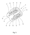
- Fig. 5
- die Abdeckeinrichtung in einer perspektivischen Ansicht von unten mit eingesetzten Verriegelungselementen,
- Fig. 6
- einen Teilschnitt durch die elektrische Steckdose gemäß dem bevorzugten Ausführungsbeispiel der Erfindung vor dem Stecken eines für die Steckdose vorgesehenen Steckers,
- Fig. 7
- einen Teilschnitt der elektrischen Steckdose gemäß dem bevorzugten Ausführungsbeispiel der Erfindung während des Steckvorgangs eines für die Steckdose vorgesehenen Steckers und
- Fig. 8
- eine perspektivische Darstellung eines Bereichs der elektrischen Steckdose gemäß dem bevorzugten Ausführungsbeispiel der Erfindung, aus dem das Zusammenwirken einer Rückholfeder mit einer Abdeckeinrichtung ersichtlich ist.
- Fig. 1
- 1 schematically shows an electrical socket according to a preferred embodiment of the invention in a perspective view,
- Fig. 2
- schematically a front view of the electrical outlet according to the preferred embodiment of the invention with removed front panel of the socket housing with two covering devices in the covering position,
- Fig. 3
- schematically the electrical outlet according to the preferred embodiment of the invention
Fig. 2 with removed protective cover and the two cover devices in the open position, - Fig. 4a, b
- the locking element of the covering device of the electrical socket according to the preferred embodiment of the invention in a side view and in a perspective view,
- Fig. 5
- the cover device in a perspective view from below with inserted locking elements,
- Fig. 6
- a partial section through the electrical outlet according to the preferred embodiment of the invention before plugging a plug provided for the socket,
- Fig. 7
- a partial section of the electrical outlet according to the preferred embodiment of the invention during the insertion of a plug provided for the plug and
- Fig. 8
- a perspective view of a portion of the electrical outlet according to the preferred embodiment of the invention, from which the interaction of a return spring with a covering is visible.
Aus
Wie
Die elektrische Steckdose 1 weist weitere Kontakte 17 auf, für die keine Abdeckeinrichtung vorgesehen ist. Außerdem ist eine in Einsteckrichtung und entgegensetzt dazu verschiebbare Zentrierhilfe 23 vorgesehen. Diese ist in einem Teilbereich des äußeren Randes der Einstecköffnung, der elektrischen Steckdose 1 angeordnet und dort beweglich an dem Dosengehäuse 3 befestigt. Die Zentrierhilfe 23 ist mit einer nicht weiter dargestellten Rückholfeder versehen, die auf die Zentrierhilfe 23 eine Kraft entgegen der Einsteckrichtung ausübt.The
Zur eigentlichen Abdeckung der Lastkontakte 7 weisen die beiden Abdeckeinrichtungen 8 jeweils ein Abdeckelement 9 auf. Die beiden Abdeckelemente 9 gewährleisten also die eigentliche mechanische Abdeckung der Lastkontakte 7, so dass sie von der Steckseite der elektrischen Steckdose 1 her in der Abdeckstellung nicht zugänglich sind. Die Abdeckeinrichtungen 8 weisen zusätzlich zu dem jeweiligen Abdeckelement 9 jeweils zwei Verriegelungselemente 10 auf, wie
Den
Aus der schon angesprochenen
In die Aufnahmeöffnungen 17 bzw. Durchgangsöffnungen 18 ist jeweils ein Verriegelungselement 10 eingesetzt, und zwar derart, dass die Verriegelungselemente 10 mit ihrem jeweiligen Auflager 16 am Ende des zweiten elastischen Arms 15 auf einem Gegenlager 19 in einem seitlichen Endbereich einer jeweiligen Durchgangsöffnung 18 der Abdeckeinrichtung 8 aufliegen.In each case, a locking
Die eigentliche Funktionsweise der Abdeckeinrichtungen 8 zur Entriegelung und nachfolgenden Überführung von der Abdeckstellung in die Öffnungsstellung, nämlich die Überführung der Klinke 12 eines Verrigelungselements 10 von ihrer Verriegelungsstellung in ihre Entriegelungsstellung und die damit ermöglichte Bewegung der Abdeckeinrichtung 8, ist insbesondere den
Dabei zeigt die
Nach dem Öffnen des Schutzdeckels 5 wird der Stecker 2 mit seinem Steckgesicht unterhalb der Zentrierhilfe 23 positioniert. Dadurch wird sichergestellt, dass beim nun folgenden Steckvorgang alle vier Taster 11 der beiden Abdeckeinrichtungen 8 von korrespondieren Stellen des Steckgesichts des Steckers 2 gleichzeitig getroffen werden.After opening the
Im aus
Kommt es nun jedoch dazu, dass die Oberseite des Tasters 11 mit Kraft beaufschlagt wird, nämlich durch einen korrespondierenden Bereich des Steckgesichts des Steckers 2 beim Steckvorgang, so wird bewirkt, dass der Taster 11 nach unten gedrückt wird, wodurch es zu einer Verformung des ersten elastischen Arms 13 und des zweiten elastischen Arms 15 des Verriegelungselement 10 kommt. Diese elastische Verformung der beiden Arme 13, 15 führt einerseits zu einer Federkraft, die den Taster 11 wieder nach oben drücken will, nämlich dadurch, dass sich der erste elastische Arm 13 mit dem Auflager 14 an dem durch einen Bereich des Dosengehäuses 3 gebildete Auflager 20 abstützt und dass sich der zweite elastische Arm 15 mit seinem Auflager 16 an dem in der Aufnahmeöffnung 7 des Verriegelungselements 10 gebildeten Gegenlager 19 abstützt. Außerdem schwenkt an der Unterseite der Abdeckeinrichtungen 8 die Klinke 12 aus der Verriegelungsöffnung 21 aus und wird damit von der Verriegelungsstellung in die Entriegelungsstellung überführt.However, if it comes to the fact that the top of the
Beim weiteren Einstecken des Steckers 2 sorgt dann die abgeschrägte Fläche 24 des Abdeckelements 9 für ein Verschieben der Abdeckeinrichtung 8 radial nach außen hin. Die Abdeckeinrichtung 8 wird dabei auf der aus den
Die nun entlasteten Taster 11 können in dieser Position nicht durch die Federrückstellkräfte der Verriegelungselemente 10 zurückgedrückt werden, da die Klinken 12 in der Entriegelungsstellung nicht mehr in die Gleitebene eintauchen können. Durch die Verschiebung der Abdeckeinrichtungen 8 radial nach außen befinden sich die Klinken 12 nämlich nicht mehr oberhalb der Verriegelungsöffnungen 21, so dass ein Zurückschwenken in die der Verriegelungsstellung entsprechenden Ausgangsstellung nicht möglich ist. Die Verriegelungselemente 10 bleiben durch die beiden elastischen Arme 13, 15, die mit ihren Auflagern 14, 16 auf einem Teil des Dosengehäuses 3 bzw. der Abdeckeinrichtung 8 aufliegen, gespannt.The now relieved
Beim Ziehen des Steckers 2 sorgen die Federkräfte aufgrund der elastischen Arme 13, 15 des Verriegelungselements 10 und der nicht weiter dargestellten Federn der Zentrierhilfe 23 sowie eine aus
- 11
- elektrische Steckdoseelectrical outlet
- 22
- Steckerplug
- 33
- Dosengehäusesocket housing
- 44
- Frontblendefront panel
- 55
- Schutzdeckelprotective cover
- 66
- Federfeather
- 77
- Lastkontakteload contacts
- 88th
- Abdeckeinrichtungcover
- 99
- Abdeckelementcover
- 1010
- Verriegelungselementlocking element
- 1111
- Tasterbutton
- 1212
- Klinkepawl
- 1313
- erster elastischer Armfirst elastic arm
- 1414
- AuflagerIn stock
- 1515
- zweiter elastischer Armsecond elastic arm
- 1616
- AuflagerIn stock
- 1717
- Aufnahmeöffnungreceiving opening
- 1818
- DurchgangsöffnungThrough opening
- 1919
- Gegenlager für Auflager des zweiten elastischen ArmsCounter bearing for support of the second elastic arm
- 2020
- Gegenlager für Auflager des ersten elastischen ArmsCounter bearing for support of the first elastic arm
- 2121
- Verriegelungsöffnunglocking opening
- 2222
- Führungguide
- 2323
- Zentrierhilfecentering
- 2424
- abgeschrägte Fläche des Abdeckelementsbevelled surface of the cover
- 2525
- Rückholfederreturn spring
Claims (10)
einem Dosengehäuse (3),
einem in dem Dosengehäuse (3) angeordneten Lastkontakt (7) und
einer Abdeckeinrichtung (8), wobei
die Abdeckeinrichtung (8) ein Abdeckelement (9) zum steckseitigen Abdecken des Lastkontaktes (7) bei nicht eingestecktem Stecker (2) aufweist, indem
das Abdeckelement (9) zwischen einer Abdeckstellung und einer Öffnungsstellung bewegbar ist, wobei
das Abdeckelement (9) in der Abdeckstellung den Lastkontakt (7) steckseitig abdeckt und in der Öffnungsstellung einen steckseitigen Zugang zu dem Lastkontakt (7) bereitstellt, dadurch gekennzeichnet, dass
die Abdeckeinrichtung (8) ein Verriegelungselement (10) aufweist, das mit einem Taster (11) und einer Klinke (12) versehen ist, wobei
der Taster (11) derart angeordnet ist, dass er von der Steckseite der Steckdose her kraftbeaufschlagbar ist,
die Klinke (12) zwischen einer Verriegelungsstellung und einer Entriegelungsstellung bewegbar ist,
die Klinke (12) in der Verriegelungsstellung in eine Verriegelungsöffnung eingreift,
die Klinke (12) in der Entriegelungsstellung aus der Verriegelungsöffnung herausgeführt ist und
der Taster (11) derart mit der Klinke (12) verbunden ist, dass mittels einer steckseitigen Kraftbeaufschlagung des Tasters (11) die Klinke (12) von der Verriegelungsstellung in die Entriegelungsstellung überführbar ist.Electrical socket, in particular charging socket, for electrical plug connection with a plug (2), with
a socket housing (3),
one in the socket housing (3) arranged load contact (7) and
a cover device (8), wherein
the cover device (8) has a cover element (9) for plug-in covering of the load contact (7) when the plug (2) is not plugged in, by
the cover element (9) is movable between a covering position and an open position, wherein
the cover element (9) in the covering position covers the load contact (7) on the plug side and in the open position provides a plug-side access to the load contact (7), characterized in that
the covering device (8) has a locking element (10) which is provided with a push-button (11) and a pawl (12), wherein
the pushbutton (11) is arranged such that it can be subjected to a force from the plug side of the socket,
the pawl (12) is movable between a locking position and an unlocking position,
engages the latch (12) in the locking position in a locking opening,
the pawl (12) in the unlocked position is led out of the locking opening and
the button (11) is connected to the pawl (12) in such a way that the pawl (12) can be transferred from the locking position into the unlocked position by means of a push-side application of force to the button (11).
Applications Claiming Priority (1)
| Application Number | Priority Date | Filing Date | Title |
|---|---|---|---|
| DE102014114214.4A DE102014114214A1 (en) | 2014-09-30 | 2014-09-30 | Electrical outlet |
Publications (2)
| Publication Number | Publication Date |
|---|---|
| EP3012920A1 true EP3012920A1 (en) | 2016-04-27 |
| EP3012920B1 EP3012920B1 (en) | 2019-05-22 |
Family
ID=54249383
Family Applications (1)
| Application Number | Title | Priority Date | Filing Date |
|---|---|---|---|
| EP15187500.2A Active EP3012920B1 (en) | 2014-09-30 | 2015-09-29 | Electric socket |
Country Status (2)
| Country | Link |
|---|---|
| EP (1) | EP3012920B1 (en) |
| DE (1) | DE102014114214A1 (en) |
Cited By (3)
| Publication number | Priority date | Publication date | Assignee | Title |
|---|---|---|---|---|
| CN109616815A (en) * | 2017-08-04 | 2019-04-12 | 哥维斯股份公司 | Connector for charging for electric vehicle |
| EP3595095A1 (en) * | 2018-07-12 | 2020-01-15 | Solteam Electronics (Dong Guan) Co., Ltd. | Industrial socket |
| CN111430975A (en) * | 2019-01-10 | 2020-07-17 | 哥维斯股份公司 | Electrical connector |
Families Citing this family (4)
| Publication number | Priority date | Publication date | Assignee | Title |
|---|---|---|---|---|
| DE102020119852A1 (en) | 2020-07-28 | 2022-02-03 | ABL SURSUM Bayerische Elektrozubehör GmbH & Co. KG | Electrical coupling, in particular electrical socket, which can be coupled with a complementary electrical coupling |
| DE102020123283A1 (en) | 2020-09-07 | 2022-03-10 | Phoenix Contact E-Mobility Gmbh | Arrangement and method for producing a plug connection between a plug and a socket |
| DE102021107290A1 (en) | 2021-03-24 | 2022-09-29 | Phoenix Contact E-Mobility Gmbh | locking device |
| BE1029233B1 (en) | 2021-03-24 | 2022-10-24 | Phoenix Contact E Mobility Gmbh | locking device |
Citations (6)
| Publication number | Priority date | Publication date | Assignee | Title |
|---|---|---|---|---|
| AT95503B (en) * | 1921-09-30 | 1924-01-10 | Progress A G | Plug contact for electrical installations. |
| GB1445055A (en) * | 1974-05-14 | 1976-08-04 | Gen Electric Co Ltd | Electric socket connectors |
| DE10225562C1 (en) * | 2002-06-10 | 2003-10-30 | Abb Patent Gmbh | Electrical wall plug socket insert with physical contact prevention device using longitudinal slider with integral resetting springs providing automatic closure bias |
| US6776630B1 (en) * | 2003-10-06 | 2004-08-17 | Atom Technology Inc. | Safety socket protective cover |
| DE102006024996A1 (en) * | 2006-05-30 | 2007-12-06 | ABL SURSUM Bayerische Elektrozubehör GmbH & Co. KG | Contact protection element for electrical coupling or electrical plug socket, has fixing part by which contact protection element is fixed in pushed-in position in contact carrier, and protection part is movable in pushed-in position |
| DE102012101755A1 (en) | 2011-03-16 | 2013-03-28 | Amad - Mennekes Holding Gmbh & Co. Kg | Electrical plug device with closure device |
Family Cites Families (4)
| Publication number | Priority date | Publication date | Assignee | Title |
|---|---|---|---|---|
| FR2740270B1 (en) * | 1995-10-24 | 1997-12-12 | Professional General Elect | CONNECTION DEVICE OF THE TYPE COMPRISING A MALE PLUG FOR INSERTION INTO A FEMALE PLUG AND INTERMEDIATE PART FOR THIS CONNECTION DEVICE |
| KR20010084128A (en) * | 2000-02-24 | 2001-09-06 | 이장우 | Concentric plug |
| DE10203894C1 (en) * | 2002-01-31 | 2003-04-30 | Abb Patent Gmbh | Electrical plug socket with physical contact protection device having wedge-shaped housing fitted to angled top face of plug socket |
| US8435055B1 (en) * | 2011-10-26 | 2013-05-07 | Leviton Manufacturing Co., Inc. | Tamper resistant electrical wiring device system |
-
2014
- 2014-09-30 DE DE102014114214.4A patent/DE102014114214A1/en not_active Ceased
-
2015
- 2015-09-29 EP EP15187500.2A patent/EP3012920B1/en active Active
Patent Citations (6)
| Publication number | Priority date | Publication date | Assignee | Title |
|---|---|---|---|---|
| AT95503B (en) * | 1921-09-30 | 1924-01-10 | Progress A G | Plug contact for electrical installations. |
| GB1445055A (en) * | 1974-05-14 | 1976-08-04 | Gen Electric Co Ltd | Electric socket connectors |
| DE10225562C1 (en) * | 2002-06-10 | 2003-10-30 | Abb Patent Gmbh | Electrical wall plug socket insert with physical contact prevention device using longitudinal slider with integral resetting springs providing automatic closure bias |
| US6776630B1 (en) * | 2003-10-06 | 2004-08-17 | Atom Technology Inc. | Safety socket protective cover |
| DE102006024996A1 (en) * | 2006-05-30 | 2007-12-06 | ABL SURSUM Bayerische Elektrozubehör GmbH & Co. KG | Contact protection element for electrical coupling or electrical plug socket, has fixing part by which contact protection element is fixed in pushed-in position in contact carrier, and protection part is movable in pushed-in position |
| DE102012101755A1 (en) | 2011-03-16 | 2013-03-28 | Amad - Mennekes Holding Gmbh & Co. Kg | Electrical plug device with closure device |
Cited By (6)
| Publication number | Priority date | Publication date | Assignee | Title |
|---|---|---|---|---|
| CN109616815A (en) * | 2017-08-04 | 2019-04-12 | 哥维斯股份公司 | Connector for charging for electric vehicle |
| CN109616815B (en) * | 2017-08-04 | 2021-07-20 | 哥维斯股份公司 | Connector for charging electric vehicle |
| EP3595095A1 (en) * | 2018-07-12 | 2020-01-15 | Solteam Electronics (Dong Guan) Co., Ltd. | Industrial socket |
| CN110718803A (en) * | 2018-07-12 | 2020-01-21 | 东莞崧腾电子有限公司 | Industrial socket |
| CN111430975A (en) * | 2019-01-10 | 2020-07-17 | 哥维斯股份公司 | Electrical connector |
| CN111430975B (en) * | 2019-01-10 | 2023-12-22 | 哥维斯股份公司 | Electric connector |
Also Published As
| Publication number | Publication date |
|---|---|
| DE102014114214A1 (en) | 2016-03-31 |
| EP3012920B1 (en) | 2019-05-22 |
Similar Documents
| Publication | Publication Date | Title |
|---|---|---|
| EP3012920B1 (en) | Electric socket | |
| EP2297824B1 (en) | Three-pole adapter set with a plug part and a socket part which may be plugged in the plug part | |
| DE102006016882B4 (en) | Connectors | |
| DE102009008109B4 (en) | Plug connection with operating lever | |
| EP1719214A1 (en) | Electric plug comprising a plug housing and at least two integrated plug-in contacts with an ejection mechanism | |
| DE1956162B2 (en) | Electrical plug connection | |
| EP2824770B1 (en) | Multiple plug socket | |
| DE102019212180A1 (en) | lever link | |
| DE102012100058B3 (en) | Housing for a computer system and computer system with such a housing | |
| DE19849883B4 (en) | Electric socket with a child safety lock | |
| EP3316414A1 (en) | Travel adapter which can be securely grounded | |
| EP3830908B1 (en) | Socket | |
| DE102014117699A1 (en) | Head clamp | |
| DE10131167A1 (en) | Connectors | |
| EP2754215A2 (en) | Housing construction set for electrical devices, in particular comprising plug apparatuses and safety means | |
| DE60103880T2 (en) | DETACHABLE COVER SYSTEM FOR MASKING A DEVICE, ESPECIALLY FOR AN ELECTRICAL OUTLET, AND ASSOCIATED ELECTRICAL DEVICE | |
| EP3403298B1 (en) | Plug connector | |
| EP3006081B1 (en) | External pacemaker/cardioverter | |
| EP1427067B1 (en) | Plug with slider for connection with a receptacle | |
| WO2019052852A1 (en) | Connection device for connecting an electrical cable | |
| EP0498056A1 (en) | Household appliance | |
| DE102018101789B4 (en) | Locking mechanism for connector housings | |
| DE102020119864A1 (en) | conductor terminal | |
| DE102012015414A1 (en) | Socket for charging battery, has closure element movable from closed position to open position, and actuator allowing closure element to move from closed position to open position, where actuator is arranged partially within ground opening | |
| DE102008032192B3 (en) | Plug-in connector, has spring element interacting with unloaded resetting pin including locking arm with locking section that is extended at angle to locking arm, where unloaded resetting pin is provided with unlocking arm |
Legal Events
| Date | Code | Title | Description |
|---|---|---|---|
| PUAI | Public reference made under article 153(3) epc to a published international application that has entered the european phase |
Free format text: ORIGINAL CODE: 0009012 |
|
| AK | Designated contracting states |
Kind code of ref document: A1 Designated state(s): AL AT BE BG CH CY CZ DE DK EE ES FI FR GB GR HR HU IE IS IT LI LT LU LV MC MK MT NL NO PL PT RO RS SE SI SK SM TR |
|
| AX | Request for extension of the european patent |
Extension state: BA ME |
|
| 17P | Request for examination filed |
Effective date: 20160729 |
|
| RBV | Designated contracting states (corrected) |
Designated state(s): AL AT BE BG CH CY CZ DE DK EE ES FI FR GB GR HR HU IE IS IT LI LT LU LV MC MK MT NL NO PL PT RO RS SE SI SK SM TR |
|
| STAA | Information on the status of an ep patent application or granted ep patent |
Free format text: STATUS: EXAMINATION IS IN PROGRESS |
|
| 17Q | First examination report despatched |
Effective date: 20170215 |
|
| GRAP | Despatch of communication of intention to grant a patent |
Free format text: ORIGINAL CODE: EPIDOSNIGR1 |
|
| STAA | Information on the status of an ep patent application or granted ep patent |
Free format text: STATUS: GRANT OF PATENT IS INTENDED |
|
| RIC1 | Information provided on ipc code assigned before grant |
Ipc: H01R 13/453 20060101AFI20181029BHEP Ipc: H01R 13/639 20060101ALN20181029BHEP |
|
| GRAJ | Information related to disapproval of communication of intention to grant by the applicant or resumption of examination proceedings by the epo deleted |
Free format text: ORIGINAL CODE: EPIDOSDIGR1 |
|
| STAA | Information on the status of an ep patent application or granted ep patent |
Free format text: STATUS: EXAMINATION IS IN PROGRESS |
|
| INTG | Intention to grant announced |
Effective date: 20181130 |
|
| GRAP | Despatch of communication of intention to grant a patent |
Free format text: ORIGINAL CODE: EPIDOSNIGR1 |
|
| STAA | Information on the status of an ep patent application or granted ep patent |
Free format text: STATUS: GRANT OF PATENT IS INTENDED |
|
| INTG | Intention to grant announced |
Effective date: 20190104 |
|
| RIC1 | Information provided on ipc code assigned before grant |
Ipc: H01R 13/639 20060101ALN20181217BHEP Ipc: H01R 13/453 20060101AFI20181217BHEP |
|
| GRAS | Grant fee paid |
Free format text: ORIGINAL CODE: EPIDOSNIGR3 |
|
| GRAA | (expected) grant |
Free format text: ORIGINAL CODE: 0009210 |
|
| STAA | Information on the status of an ep patent application or granted ep patent |
Free format text: STATUS: THE PATENT HAS BEEN GRANTED |
|
| AK | Designated contracting states |
Kind code of ref document: B1 Designated state(s): AL AT BE BG CH CY CZ DE DK EE ES FI FR GB GR HR HU IE IS IT LI LT LU LV MC MK MT NL NO PL PT RO RS SE SI SK SM TR |
|
| REG | Reference to a national code |
Ref country code: GB Ref legal event code: FG4D Free format text: NOT ENGLISH |
|
| REG | Reference to a national code |
Ref country code: CH Ref legal event code: EP |
|
| REG | Reference to a national code |
Ref country code: IE Ref legal event code: FG4D Free format text: LANGUAGE OF EP DOCUMENT: GERMAN |
|
| REG | Reference to a national code |
Ref country code: DE Ref legal event code: R096 Ref document number: 502015009115 Country of ref document: DE |
|
| REG | Reference to a national code |
Ref country code: AT Ref legal event code: REF Ref document number: 1137234 Country of ref document: AT Kind code of ref document: T Effective date: 20190615 |
|
| REG | Reference to a national code |
Ref country code: NL Ref legal event code: MP Effective date: 20190522 |
|
| REG | Reference to a national code |
Ref country code: LT Ref legal event code: MG4D |
|
| PG25 | Lapsed in a contracting state [announced via postgrant information from national office to epo] |
Ref country code: NO Free format text: LAPSE BECAUSE OF FAILURE TO SUBMIT A TRANSLATION OF THE DESCRIPTION OR TO PAY THE FEE WITHIN THE PRESCRIBED TIME-LIMIT Effective date: 20190822 Ref country code: LT Free format text: LAPSE BECAUSE OF FAILURE TO SUBMIT A TRANSLATION OF THE DESCRIPTION OR TO PAY THE FEE WITHIN THE PRESCRIBED TIME-LIMIT Effective date: 20190522 Ref country code: FI Free format text: LAPSE BECAUSE OF FAILURE TO SUBMIT A TRANSLATION OF THE DESCRIPTION OR TO PAY THE FEE WITHIN THE PRESCRIBED TIME-LIMIT Effective date: 20190522 Ref country code: NL Free format text: LAPSE BECAUSE OF FAILURE TO SUBMIT A TRANSLATION OF THE DESCRIPTION OR TO PAY THE FEE WITHIN THE PRESCRIBED TIME-LIMIT Effective date: 20190522 Ref country code: ES Free format text: LAPSE BECAUSE OF FAILURE TO SUBMIT A TRANSLATION OF THE DESCRIPTION OR TO PAY THE FEE WITHIN THE PRESCRIBED TIME-LIMIT Effective date: 20190522 Ref country code: AL Free format text: LAPSE BECAUSE OF FAILURE TO SUBMIT A TRANSLATION OF THE DESCRIPTION OR TO PAY THE FEE WITHIN THE PRESCRIBED TIME-LIMIT Effective date: 20190522 Ref country code: PT Free format text: LAPSE BECAUSE OF FAILURE TO SUBMIT A TRANSLATION OF THE DESCRIPTION OR TO PAY THE FEE WITHIN THE PRESCRIBED TIME-LIMIT Effective date: 20190922 Ref country code: SE Free format text: LAPSE BECAUSE OF FAILURE TO SUBMIT A TRANSLATION OF THE DESCRIPTION OR TO PAY THE FEE WITHIN THE PRESCRIBED TIME-LIMIT Effective date: 20190522 Ref country code: HR Free format text: LAPSE BECAUSE OF FAILURE TO SUBMIT A TRANSLATION OF THE DESCRIPTION OR TO PAY THE FEE WITHIN THE PRESCRIBED TIME-LIMIT Effective date: 20190522 |
|
| PG25 | Lapsed in a contracting state [announced via postgrant information from national office to epo] |
Ref country code: RS Free format text: LAPSE BECAUSE OF FAILURE TO SUBMIT A TRANSLATION OF THE DESCRIPTION OR TO PAY THE FEE WITHIN THE PRESCRIBED TIME-LIMIT Effective date: 20190522 Ref country code: LV Free format text: LAPSE BECAUSE OF FAILURE TO SUBMIT A TRANSLATION OF THE DESCRIPTION OR TO PAY THE FEE WITHIN THE PRESCRIBED TIME-LIMIT Effective date: 20190522 Ref country code: GR Free format text: LAPSE BECAUSE OF FAILURE TO SUBMIT A TRANSLATION OF THE DESCRIPTION OR TO PAY THE FEE WITHIN THE PRESCRIBED TIME-LIMIT Effective date: 20190823 Ref country code: BG Free format text: LAPSE BECAUSE OF FAILURE TO SUBMIT A TRANSLATION OF THE DESCRIPTION OR TO PAY THE FEE WITHIN THE PRESCRIBED TIME-LIMIT Effective date: 20190822 |
|
| PG25 | Lapsed in a contracting state [announced via postgrant information from national office to epo] |
Ref country code: EE Free format text: LAPSE BECAUSE OF FAILURE TO SUBMIT A TRANSLATION OF THE DESCRIPTION OR TO PAY THE FEE WITHIN THE PRESCRIBED TIME-LIMIT Effective date: 20190522 Ref country code: CZ Free format text: LAPSE BECAUSE OF FAILURE TO SUBMIT A TRANSLATION OF THE DESCRIPTION OR TO PAY THE FEE WITHIN THE PRESCRIBED TIME-LIMIT Effective date: 20190522 Ref country code: RO Free format text: LAPSE BECAUSE OF FAILURE TO SUBMIT A TRANSLATION OF THE DESCRIPTION OR TO PAY THE FEE WITHIN THE PRESCRIBED TIME-LIMIT Effective date: 20190522 Ref country code: DK Free format text: LAPSE BECAUSE OF FAILURE TO SUBMIT A TRANSLATION OF THE DESCRIPTION OR TO PAY THE FEE WITHIN THE PRESCRIBED TIME-LIMIT Effective date: 20190522 Ref country code: SK Free format text: LAPSE BECAUSE OF FAILURE TO SUBMIT A TRANSLATION OF THE DESCRIPTION OR TO PAY THE FEE WITHIN THE PRESCRIBED TIME-LIMIT Effective date: 20190522 |
|
| REG | Reference to a national code |
Ref country code: DE Ref legal event code: R097 Ref document number: 502015009115 Country of ref document: DE |
|
| PG25 | Lapsed in a contracting state [announced via postgrant information from national office to epo] |
Ref country code: SM Free format text: LAPSE BECAUSE OF FAILURE TO SUBMIT A TRANSLATION OF THE DESCRIPTION OR TO PAY THE FEE WITHIN THE PRESCRIBED TIME-LIMIT Effective date: 20190522 Ref country code: IT Free format text: LAPSE BECAUSE OF FAILURE TO SUBMIT A TRANSLATION OF THE DESCRIPTION OR TO PAY THE FEE WITHIN THE PRESCRIBED TIME-LIMIT Effective date: 20190522 |
|
| PLBE | No opposition filed within time limit |
Free format text: ORIGINAL CODE: 0009261 |
|
| STAA | Information on the status of an ep patent application or granted ep patent |
Free format text: STATUS: NO OPPOSITION FILED WITHIN TIME LIMIT |
|
| PG25 | Lapsed in a contracting state [announced via postgrant information from national office to epo] |
Ref country code: TR Free format text: LAPSE BECAUSE OF FAILURE TO SUBMIT A TRANSLATION OF THE DESCRIPTION OR TO PAY THE FEE WITHIN THE PRESCRIBED TIME-LIMIT Effective date: 20190522 |
|
| 26N | No opposition filed |
Effective date: 20200225 |
|
| PG25 | Lapsed in a contracting state [announced via postgrant information from national office to epo] |
Ref country code: PL Free format text: LAPSE BECAUSE OF FAILURE TO SUBMIT A TRANSLATION OF THE DESCRIPTION OR TO PAY THE FEE WITHIN THE PRESCRIBED TIME-LIMIT Effective date: 20190522 |
|
| PG25 | Lapsed in a contracting state [announced via postgrant information from national office to epo] |
Ref country code: SI Free format text: LAPSE BECAUSE OF FAILURE TO SUBMIT A TRANSLATION OF THE DESCRIPTION OR TO PAY THE FEE WITHIN THE PRESCRIBED TIME-LIMIT Effective date: 20190522 Ref country code: MC Free format text: LAPSE BECAUSE OF FAILURE TO SUBMIT A TRANSLATION OF THE DESCRIPTION OR TO PAY THE FEE WITHIN THE PRESCRIBED TIME-LIMIT Effective date: 20190522 |
|
| REG | Reference to a national code |
Ref country code: CH Ref legal event code: PL |
|
| PG25 | Lapsed in a contracting state [announced via postgrant information from national office to epo] |
Ref country code: LU Free format text: LAPSE BECAUSE OF NON-PAYMENT OF DUE FEES Effective date: 20190929 Ref country code: CH Free format text: LAPSE BECAUSE OF NON-PAYMENT OF DUE FEES Effective date: 20190930 Ref country code: IE Free format text: LAPSE BECAUSE OF NON-PAYMENT OF DUE FEES Effective date: 20190929 Ref country code: LI Free format text: LAPSE BECAUSE OF NON-PAYMENT OF DUE FEES Effective date: 20190930 |
|
| REG | Reference to a national code |
Ref country code: BE Ref legal event code: MM Effective date: 20190930 |
|
| PG25 | Lapsed in a contracting state [announced via postgrant information from national office to epo] |
Ref country code: BE Free format text: LAPSE BECAUSE OF NON-PAYMENT OF DUE FEES Effective date: 20190930 |
|
| GBPC | Gb: european patent ceased through non-payment of renewal fee |
Effective date: 20190929 |
|
| PG25 | Lapsed in a contracting state [announced via postgrant information from national office to epo] |
Ref country code: GB Free format text: LAPSE BECAUSE OF NON-PAYMENT OF DUE FEES Effective date: 20190929 |
|
| PG25 | Lapsed in a contracting state [announced via postgrant information from national office to epo] |
Ref country code: CY Free format text: LAPSE BECAUSE OF FAILURE TO SUBMIT A TRANSLATION OF THE DESCRIPTION OR TO PAY THE FEE WITHIN THE PRESCRIBED TIME-LIMIT Effective date: 20190522 |
|
| PG25 | Lapsed in a contracting state [announced via postgrant information from national office to epo] |
Ref country code: IS Free format text: LAPSE BECAUSE OF FAILURE TO SUBMIT A TRANSLATION OF THE DESCRIPTION OR TO PAY THE FEE WITHIN THE PRESCRIBED TIME-LIMIT Effective date: 20190922 |
|
| PG25 | Lapsed in a contracting state [announced via postgrant information from national office to epo] |
Ref country code: HU Free format text: LAPSE BECAUSE OF FAILURE TO SUBMIT A TRANSLATION OF THE DESCRIPTION OR TO PAY THE FEE WITHIN THE PRESCRIBED TIME-LIMIT; INVALID AB INITIO Effective date: 20150929 Ref country code: MT Free format text: LAPSE BECAUSE OF FAILURE TO SUBMIT A TRANSLATION OF THE DESCRIPTION OR TO PAY THE FEE WITHIN THE PRESCRIBED TIME-LIMIT Effective date: 20190522 Ref country code: FR Free format text: LAPSE BECAUSE OF NON-PAYMENT OF DUE FEES Effective date: 20190930 |
|
| REG | Reference to a national code |
Ref country code: DE Ref legal event code: R084 Ref document number: 502015009115 Country of ref document: DE |
|
| REG | Reference to a national code |
Ref country code: AT Ref legal event code: MM01 Ref document number: 1137234 Country of ref document: AT Kind code of ref document: T Effective date: 20200929 |
|
| PG25 | Lapsed in a contracting state [announced via postgrant information from national office to epo] |
Ref country code: AT Free format text: LAPSE BECAUSE OF NON-PAYMENT OF DUE FEES Effective date: 20200929 |
|
| PG25 | Lapsed in a contracting state [announced via postgrant information from national office to epo] |
Ref country code: MK Free format text: LAPSE BECAUSE OF FAILURE TO SUBMIT A TRANSLATION OF THE DESCRIPTION OR TO PAY THE FEE WITHIN THE PRESCRIBED TIME-LIMIT Effective date: 20190522 |
|
| P01 | Opt-out of the competence of the unified patent court (upc) registered |
Effective date: 20230525 |
|
| P02 | Opt-out of the competence of the unified patent court (upc) changed |
Effective date: 20230530 |
|
| PGFP | Annual fee paid to national office [announced via postgrant information from national office to epo] |
Ref country code: DE Payment date: 20231127 Year of fee payment: 9 |