EP3001993A1 - Absorbent article demonstrating controlled deformation and longitudinal fluid distribution - Google Patents
Absorbent article demonstrating controlled deformation and longitudinal fluid distribution Download PDFInfo
- Publication number
- EP3001993A1 EP3001993A1 EP15187473.2A EP15187473A EP3001993A1 EP 3001993 A1 EP3001993 A1 EP 3001993A1 EP 15187473 A EP15187473 A EP 15187473A EP 3001993 A1 EP3001993 A1 EP 3001993A1
- Authority
- EP
- European Patent Office
- Prior art keywords
- longitudinally extending
- channels
- central
- region
- centerline
- Prior art date
- Legal status (The legal status is an assumption and is not a legal conclusion. Google has not performed a legal analysis and makes no representation as to the accuracy of the status listed.)
- Granted
Links
- 230000002745 absorbent Effects 0.000 title claims abstract description 151
- 239000002250 absorbent Substances 0.000 title claims abstract description 151
- 239000012530 fluid Substances 0.000 title claims abstract description 49
- 238000009826 distribution Methods 0.000 title description 17
- 238000004049 embossing Methods 0.000 claims description 117
- 238000004891 communication Methods 0.000 claims description 8
- 239000010410 layer Substances 0.000 description 92
- 239000000463 material Substances 0.000 description 28
- 238000012360 testing method Methods 0.000 description 26
- 239000000835 fiber Substances 0.000 description 20
- 230000006835 compression Effects 0.000 description 16
- 238000007906 compression Methods 0.000 description 16
- 230000004888 barrier function Effects 0.000 description 13
- 238000012546 transfer Methods 0.000 description 12
- 229920000247 superabsorbent polymer Polymers 0.000 description 9
- 239000004744 fabric Substances 0.000 description 8
- 210000001124 body fluid Anatomy 0.000 description 7
- 238000000034 method Methods 0.000 description 7
- FAPWRFPIFSIZLT-UHFFFAOYSA-M Sodium chloride Chemical compound [Na+].[Cl-] FAPWRFPIFSIZLT-UHFFFAOYSA-M 0.000 description 6
- 239000000853 adhesive Substances 0.000 description 6
- 230000001070 adhesive effect Effects 0.000 description 6
- 239000010839 body fluid Substances 0.000 description 6
- 229920000728 polyester Polymers 0.000 description 6
- -1 polypropylene Polymers 0.000 description 6
- 230000000052 comparative effect Effects 0.000 description 5
- 239000007788 liquid Substances 0.000 description 5
- 229920001131 Pulp (paper) Polymers 0.000 description 4
- 238000013461 design Methods 0.000 description 4
- 239000000203 mixture Substances 0.000 description 4
- 238000011179 visual inspection Methods 0.000 description 4
- 229920000742 Cotton Polymers 0.000 description 3
- 239000004698 Polyethylene Substances 0.000 description 3
- 239000004743 Polypropylene Substances 0.000 description 3
- 229920000297 Rayon Polymers 0.000 description 3
- 230000002175 menstrual effect Effects 0.000 description 3
- 239000000123 paper Substances 0.000 description 3
- 239000002245 particle Substances 0.000 description 3
- 229920000573 polyethylene Polymers 0.000 description 3
- 229920001155 polypropylene Polymers 0.000 description 3
- 239000011148 porous material Substances 0.000 description 3
- 239000002964 rayon Substances 0.000 description 3
- 239000011780 sodium chloride Substances 0.000 description 3
- 238000010998 test method Methods 0.000 description 3
- QCDWFXQBSFUVSP-UHFFFAOYSA-N 2-phenoxyethanol Chemical compound OCCOC1=CC=CC=C1 QCDWFXQBSFUVSP-UHFFFAOYSA-N 0.000 description 2
- PEDCQBHIVMGVHV-UHFFFAOYSA-N Glycerine Chemical compound OCC(O)CO PEDCQBHIVMGVHV-UHFFFAOYSA-N 0.000 description 2
- 239000002390 adhesive tape Substances 0.000 description 2
- 230000001174 ascending effect Effects 0.000 description 2
- 150000001875 compounds Chemical class 0.000 description 2
- 239000006260 foam Substances 0.000 description 2
- 238000004519 manufacturing process Methods 0.000 description 2
- 230000008018 melting Effects 0.000 description 2
- 238000002844 melting Methods 0.000 description 2
- 230000035515 penetration Effects 0.000 description 2
- 238000007639 printing Methods 0.000 description 2
- 230000002940 repellent Effects 0.000 description 2
- 239000005871 repellent Substances 0.000 description 2
- 239000002356 single layer Substances 0.000 description 2
- 239000011122 softwood Substances 0.000 description 2
- 239000004094 surface-active agent Substances 0.000 description 2
- 229920001169 thermoplastic Polymers 0.000 description 2
- 239000004416 thermosoftening plastic Substances 0.000 description 2
- 229920002972 Acrylic fiber Polymers 0.000 description 1
- 229920003043 Cellulose fiber Polymers 0.000 description 1
- 229920002907 Guar gum Polymers 0.000 description 1
- 240000006240 Linum usitatissimum Species 0.000 description 1
- 235000004431 Linum usitatissimum Nutrition 0.000 description 1
- 241001274656 Marisa Species 0.000 description 1
- 239000004677 Nylon Substances 0.000 description 1
- 229920003171 Poly (ethylene oxide) Polymers 0.000 description 1
- 244000236580 Psidium pyriferum Species 0.000 description 1
- 235000013929 Psidium pyriferum Nutrition 0.000 description 1
- 229920002472 Starch Polymers 0.000 description 1
- 229910000831 Steel Inorganic materials 0.000 description 1
- LSNNMFCWUKXFEE-UHFFFAOYSA-N Sulfurous acid Chemical compound OS(O)=O LSNNMFCWUKXFEE-UHFFFAOYSA-N 0.000 description 1
- 238000010521 absorption reaction Methods 0.000 description 1
- 239000002253 acid Substances 0.000 description 1
- NIXOWILDQLNWCW-UHFFFAOYSA-N acrylic acid group Chemical group C(C=C)(=O)O NIXOWILDQLNWCW-UHFFFAOYSA-N 0.000 description 1
- 230000008901 benefit Effects 0.000 description 1
- 239000011230 binding agent Substances 0.000 description 1
- 230000015572 biosynthetic process Effects 0.000 description 1
- 229920002678 cellulose Polymers 0.000 description 1
- 239000001913 cellulose Substances 0.000 description 1
- 239000003795 chemical substances by application Substances 0.000 description 1
- 238000010276 construction Methods 0.000 description 1
- 238000007796 conventional method Methods 0.000 description 1
- 229920001577 copolymer Polymers 0.000 description 1
- 238000002788 crimping Methods 0.000 description 1
- 239000003431 cross linking reagent Substances 0.000 description 1
- 239000013078 crystal Substances 0.000 description 1
- 230000008021 deposition Effects 0.000 description 1
- 239000013013 elastic material Substances 0.000 description 1
- 229910001651 emery Inorganic materials 0.000 description 1
- 238000005530 etching Methods 0.000 description 1
- 230000001747 exhibiting effect Effects 0.000 description 1
- 230000004438 eyesight Effects 0.000 description 1
- 239000002657 fibrous material Substances 0.000 description 1
- 235000011187 glycerol Nutrition 0.000 description 1
- 239000008187 granular material Substances 0.000 description 1
- 239000000665 guar gum Substances 0.000 description 1
- 235000010417 guar gum Nutrition 0.000 description 1
- 229960002154 guar gum Drugs 0.000 description 1
- 239000011121 hardwood Substances 0.000 description 1
- 229920001477 hydrophilic polymer Polymers 0.000 description 1
- 230000002209 hydrophobic effect Effects 0.000 description 1
- 230000004305 hyperopia Effects 0.000 description 1
- 201000006318 hyperopia Diseases 0.000 description 1
- 238000005286 illumination Methods 0.000 description 1
- 238000007689 inspection Methods 0.000 description 1
- 230000001788 irregular Effects 0.000 description 1
- 239000002655 kraft paper Substances 0.000 description 1
- 238000010147 laser engraving Methods 0.000 description 1
- 230000007246 mechanism Effects 0.000 description 1
- 238000012986 modification Methods 0.000 description 1
- 230000004048 modification Effects 0.000 description 1
- 239000000178 monomer Substances 0.000 description 1
- 230000004379 myopia Effects 0.000 description 1
- 208000001491 myopia Diseases 0.000 description 1
- 239000004745 nonwoven fabric Substances 0.000 description 1
- 229920001778 nylon Polymers 0.000 description 1
- 239000003960 organic solvent Substances 0.000 description 1
- 238000004806 packaging method and process Methods 0.000 description 1
- 239000003415 peat Substances 0.000 description 1
- 229960005323 phenoxyethanol Drugs 0.000 description 1
- 230000000704 physical effect Effects 0.000 description 1
- 229920000058 polyacrylate Polymers 0.000 description 1
- 229920006254 polymer film Polymers 0.000 description 1
- 229920002451 polyvinyl alcohol Polymers 0.000 description 1
- 235000019422 polyvinyl alcohol Nutrition 0.000 description 1
- 239000000843 powder Substances 0.000 description 1
- 238000002360 preparation method Methods 0.000 description 1
- 230000008569 process Effects 0.000 description 1
- 238000004537 pulping Methods 0.000 description 1
- 230000009467 reduction Effects 0.000 description 1
- 238000007789 sealing Methods 0.000 description 1
- 241000894007 species Species 0.000 description 1
- 230000000087 stabilizing effect Effects 0.000 description 1
- 238000010186 staining Methods 0.000 description 1
- 238000010561 standard procedure Methods 0.000 description 1
- 235000019698 starch Nutrition 0.000 description 1
- 239000010959 steel Substances 0.000 description 1
- 239000000126 substance Substances 0.000 description 1
- 229920002994 synthetic fiber Polymers 0.000 description 1
- 239000012815 thermoplastic material Substances 0.000 description 1
- 125000000391 vinyl group Chemical group [H]C([*])=C([H])[H] 0.000 description 1
- 229920002554 vinyl polymer Polymers 0.000 description 1
- 230000000007 visual effect Effects 0.000 description 1
- XLYOFNOQVPJJNP-UHFFFAOYSA-N water Substances O XLYOFNOQVPJJNP-UHFFFAOYSA-N 0.000 description 1
- 238000009736 wetting Methods 0.000 description 1
- 239000000230 xanthan gum Substances 0.000 description 1
- 229920001285 xanthan gum Polymers 0.000 description 1
- 235000010493 xanthan gum Nutrition 0.000 description 1
- 229940082509 xanthan gum Drugs 0.000 description 1
Images


Classifications
-
- A—HUMAN NECESSITIES
- A61—MEDICAL OR VETERINARY SCIENCE; HYGIENE
- A61F—FILTERS IMPLANTABLE INTO BLOOD VESSELS; PROSTHESES; DEVICES PROVIDING PATENCY TO, OR PREVENTING COLLAPSING OF, TUBULAR STRUCTURES OF THE BODY, e.g. STENTS; ORTHOPAEDIC, NURSING OR CONTRACEPTIVE DEVICES; FOMENTATION; TREATMENT OR PROTECTION OF EYES OR EARS; BANDAGES, DRESSINGS OR ABSORBENT PADS; FIRST-AID KITS
- A61F13/00—Bandages or dressings; Absorbent pads
- A61F13/15—Absorbent pads, e.g. sanitary towels, swabs or tampons for external or internal application to the body; Supporting or fastening means therefor; Tampon applicators
- A61F13/45—Absorbent pads, e.g. sanitary towels, swabs or tampons for external or internal application to the body; Supporting or fastening means therefor; Tampon applicators characterised by the shape
- A61F13/47—Sanitary towels, incontinence pads or napkins
- A61F13/472—Sanitary towels, incontinence pads or napkins specially adapted for female use
- A61F13/47236—Sanitary towels, incontinence pads or napkins specially adapted for female use characterised by an unusual contour
-
- A—HUMAN NECESSITIES
- A61—MEDICAL OR VETERINARY SCIENCE; HYGIENE
- A61F—FILTERS IMPLANTABLE INTO BLOOD VESSELS; PROSTHESES; DEVICES PROVIDING PATENCY TO, OR PREVENTING COLLAPSING OF, TUBULAR STRUCTURES OF THE BODY, e.g. STENTS; ORTHOPAEDIC, NURSING OR CONTRACEPTIVE DEVICES; FOMENTATION; TREATMENT OR PROTECTION OF EYES OR EARS; BANDAGES, DRESSINGS OR ABSORBENT PADS; FIRST-AID KITS
- A61F13/00—Bandages or dressings; Absorbent pads
- A61F13/15—Absorbent pads, e.g. sanitary towels, swabs or tampons for external or internal application to the body; Supporting or fastening means therefor; Tampon applicators
- A61F13/53—Absorbent pads, e.g. sanitary towels, swabs or tampons for external or internal application to the body; Supporting or fastening means therefor; Tampon applicators characterised by the absorbing medium
- A61F13/534—Absorbent pads, e.g. sanitary towels, swabs or tampons for external or internal application to the body; Supporting or fastening means therefor; Tampon applicators characterised by the absorbing medium having an inhomogeneous composition through the thickness of the pad
- A61F13/537—Absorbent pads, e.g. sanitary towels, swabs or tampons for external or internal application to the body; Supporting or fastening means therefor; Tampon applicators characterised by the absorbing medium having an inhomogeneous composition through the thickness of the pad characterised by a layer facilitating or inhibiting flow in one direction or plane, e.g. a wicking layer
-
- A—HUMAN NECESSITIES
- A61—MEDICAL OR VETERINARY SCIENCE; HYGIENE
- A61F—FILTERS IMPLANTABLE INTO BLOOD VESSELS; PROSTHESES; DEVICES PROVIDING PATENCY TO, OR PREVENTING COLLAPSING OF, TUBULAR STRUCTURES OF THE BODY, e.g. STENTS; ORTHOPAEDIC, NURSING OR CONTRACEPTIVE DEVICES; FOMENTATION; TREATMENT OR PROTECTION OF EYES OR EARS; BANDAGES, DRESSINGS OR ABSORBENT PADS; FIRST-AID KITS
- A61F13/00—Bandages or dressings; Absorbent pads
- A61F13/15—Absorbent pads, e.g. sanitary towels, swabs or tampons for external or internal application to the body; Supporting or fastening means therefor; Tampon applicators
- A61F13/51—Absorbent pads, e.g. sanitary towels, swabs or tampons for external or internal application to the body; Supporting or fastening means therefor; Tampon applicators characterised by the outer layers
- A61F13/511—Topsheet, i.e. the permeable cover or layer facing the skin
- A61F13/51104—Topsheet, i.e. the permeable cover or layer facing the skin the top sheet having a three-dimensional cross-section, e.g. corrugations, embossments, recesses or projections
- A61F13/51108—Topsheet, i.e. the permeable cover or layer facing the skin the top sheet having a three-dimensional cross-section, e.g. corrugations, embossments, recesses or projections the top sheet having corrugations or embossments having one axis relatively longer than the other axis, e.g. forming channels or grooves in a longitudinal direction
-
- A—HUMAN NECESSITIES
- A61—MEDICAL OR VETERINARY SCIENCE; HYGIENE
- A61F—FILTERS IMPLANTABLE INTO BLOOD VESSELS; PROSTHESES; DEVICES PROVIDING PATENCY TO, OR PREVENTING COLLAPSING OF, TUBULAR STRUCTURES OF THE BODY, e.g. STENTS; ORTHOPAEDIC, NURSING OR CONTRACEPTIVE DEVICES; FOMENTATION; TREATMENT OR PROTECTION OF EYES OR EARS; BANDAGES, DRESSINGS OR ABSORBENT PADS; FIRST-AID KITS
- A61F13/00—Bandages or dressings; Absorbent pads
- A61F13/15—Absorbent pads, e.g. sanitary towels, swabs or tampons for external or internal application to the body; Supporting or fastening means therefor; Tampon applicators
- A61F13/45—Absorbent pads, e.g. sanitary towels, swabs or tampons for external or internal application to the body; Supporting or fastening means therefor; Tampon applicators characterised by the shape
- A61F13/47—Sanitary towels, incontinence pads or napkins
- A61F13/472—Sanitary towels, incontinence pads or napkins specially adapted for female use
- A61F13/47218—Sanitary towels, incontinence pads or napkins specially adapted for female use with a raised crotch region, e.g. hump
-
- A—HUMAN NECESSITIES
- A61—MEDICAL OR VETERINARY SCIENCE; HYGIENE
- A61F—FILTERS IMPLANTABLE INTO BLOOD VESSELS; PROSTHESES; DEVICES PROVIDING PATENCY TO, OR PREVENTING COLLAPSING OF, TUBULAR STRUCTURES OF THE BODY, e.g. STENTS; ORTHOPAEDIC, NURSING OR CONTRACEPTIVE DEVICES; FOMENTATION; TREATMENT OR PROTECTION OF EYES OR EARS; BANDAGES, DRESSINGS OR ABSORBENT PADS; FIRST-AID KITS
- A61F13/00—Bandages or dressings; Absorbent pads
- A61F13/15—Absorbent pads, e.g. sanitary towels, swabs or tampons for external or internal application to the body; Supporting or fastening means therefor; Tampon applicators
- A61F13/45—Absorbent pads, e.g. sanitary towels, swabs or tampons for external or internal application to the body; Supporting or fastening means therefor; Tampon applicators characterised by the shape
- A61F13/47—Sanitary towels, incontinence pads or napkins
- A61F13/475—Sanitary towels, incontinence pads or napkins characterised by edge leakage prevention means
- A61F13/4751—Sanitary towels, incontinence pads or napkins characterised by edge leakage prevention means the means preventing fluid flow in a transversal direction
- A61F13/4756—Sanitary towels, incontinence pads or napkins characterised by edge leakage prevention means the means preventing fluid flow in a transversal direction the means consisting of grooves, e.g. channels, depressions or embossments, resulting in a heterogeneous surface level
-
- A—HUMAN NECESSITIES
- A61—MEDICAL OR VETERINARY SCIENCE; HYGIENE
- A61F—FILTERS IMPLANTABLE INTO BLOOD VESSELS; PROSTHESES; DEVICES PROVIDING PATENCY TO, OR PREVENTING COLLAPSING OF, TUBULAR STRUCTURES OF THE BODY, e.g. STENTS; ORTHOPAEDIC, NURSING OR CONTRACEPTIVE DEVICES; FOMENTATION; TREATMENT OR PROTECTION OF EYES OR EARS; BANDAGES, DRESSINGS OR ABSORBENT PADS; FIRST-AID KITS
- A61F13/00—Bandages or dressings; Absorbent pads
- A61F13/15—Absorbent pads, e.g. sanitary towels, swabs or tampons for external or internal application to the body; Supporting or fastening means therefor; Tampon applicators
- A61F13/51—Absorbent pads, e.g. sanitary towels, swabs or tampons for external or internal application to the body; Supporting or fastening means therefor; Tampon applicators characterised by the outer layers
- A61F13/511—Topsheet, i.e. the permeable cover or layer facing the skin
- A61F13/51104—Topsheet, i.e. the permeable cover or layer facing the skin the top sheet having a three-dimensional cross-section, e.g. corrugations, embossments, recesses or projections
-
- A—HUMAN NECESSITIES
- A61—MEDICAL OR VETERINARY SCIENCE; HYGIENE
- A61F—FILTERS IMPLANTABLE INTO BLOOD VESSELS; PROSTHESES; DEVICES PROVIDING PATENCY TO, OR PREVENTING COLLAPSING OF, TUBULAR STRUCTURES OF THE BODY, e.g. STENTS; ORTHOPAEDIC, NURSING OR CONTRACEPTIVE DEVICES; FOMENTATION; TREATMENT OR PROTECTION OF EYES OR EARS; BANDAGES, DRESSINGS OR ABSORBENT PADS; FIRST-AID KITS
- A61F13/00—Bandages or dressings; Absorbent pads
- A61F13/15—Absorbent pads, e.g. sanitary towels, swabs or tampons for external or internal application to the body; Supporting or fastening means therefor; Tampon applicators
- A61F13/53—Absorbent pads, e.g. sanitary towels, swabs or tampons for external or internal application to the body; Supporting or fastening means therefor; Tampon applicators characterised by the absorbing medium
- A61F13/531—Absorbent pads, e.g. sanitary towels, swabs or tampons for external or internal application to the body; Supporting or fastening means therefor; Tampon applicators characterised by the absorbing medium having a homogeneous composition through the thickness of the pad
- A61F13/532—Absorbent pads, e.g. sanitary towels, swabs or tampons for external or internal application to the body; Supporting or fastening means therefor; Tampon applicators characterised by the absorbing medium having a homogeneous composition through the thickness of the pad inhomogeneous in the plane of the pad
- A61F13/533—Absorbent pads, e.g. sanitary towels, swabs or tampons for external or internal application to the body; Supporting or fastening means therefor; Tampon applicators characterised by the absorbing medium having a homogeneous composition through the thickness of the pad inhomogeneous in the plane of the pad having discontinuous areas of compression
-
- A—HUMAN NECESSITIES
- A61—MEDICAL OR VETERINARY SCIENCE; HYGIENE
- A61F—FILTERS IMPLANTABLE INTO BLOOD VESSELS; PROSTHESES; DEVICES PROVIDING PATENCY TO, OR PREVENTING COLLAPSING OF, TUBULAR STRUCTURES OF THE BODY, e.g. STENTS; ORTHOPAEDIC, NURSING OR CONTRACEPTIVE DEVICES; FOMENTATION; TREATMENT OR PROTECTION OF EYES OR EARS; BANDAGES, DRESSINGS OR ABSORBENT PADS; FIRST-AID KITS
- A61F13/00—Bandages or dressings; Absorbent pads
- A61F13/15—Absorbent pads, e.g. sanitary towels, swabs or tampons for external or internal application to the body; Supporting or fastening means therefor; Tampon applicators
- A61F13/53—Absorbent pads, e.g. sanitary towels, swabs or tampons for external or internal application to the body; Supporting or fastening means therefor; Tampon applicators characterised by the absorbing medium
- A61F13/534—Absorbent pads, e.g. sanitary towels, swabs or tampons for external or internal application to the body; Supporting or fastening means therefor; Tampon applicators characterised by the absorbing medium having an inhomogeneous composition through the thickness of the pad
- A61F13/535—Absorbent pads, e.g. sanitary towels, swabs or tampons for external or internal application to the body; Supporting or fastening means therefor; Tampon applicators characterised by the absorbing medium having an inhomogeneous composition through the thickness of the pad inhomogeneous in the plane of the pad, e.g. core absorbent layers being of different sizes
- A61F13/536—Absorbent pads, e.g. sanitary towels, swabs or tampons for external or internal application to the body; Supporting or fastening means therefor; Tampon applicators characterised by the absorbing medium having an inhomogeneous composition through the thickness of the pad inhomogeneous in the plane of the pad, e.g. core absorbent layers being of different sizes having discontinuous areas of compression
-
- A—HUMAN NECESSITIES
- A61—MEDICAL OR VETERINARY SCIENCE; HYGIENE
- A61F—FILTERS IMPLANTABLE INTO BLOOD VESSELS; PROSTHESES; DEVICES PROVIDING PATENCY TO, OR PREVENTING COLLAPSING OF, TUBULAR STRUCTURES OF THE BODY, e.g. STENTS; ORTHOPAEDIC, NURSING OR CONTRACEPTIVE DEVICES; FOMENTATION; TREATMENT OR PROTECTION OF EYES OR EARS; BANDAGES, DRESSINGS OR ABSORBENT PADS; FIRST-AID KITS
- A61F13/00—Bandages or dressings; Absorbent pads
- A61F13/15—Absorbent pads, e.g. sanitary towels, swabs or tampons for external or internal application to the body; Supporting or fastening means therefor; Tampon applicators
- A61F13/53—Absorbent pads, e.g. sanitary towels, swabs or tampons for external or internal application to the body; Supporting or fastening means therefor; Tampon applicators characterised by the absorbing medium
- A61F13/534—Absorbent pads, e.g. sanitary towels, swabs or tampons for external or internal application to the body; Supporting or fastening means therefor; Tampon applicators characterised by the absorbing medium having an inhomogeneous composition through the thickness of the pad
- A61F13/537—Absorbent pads, e.g. sanitary towels, swabs or tampons for external or internal application to the body; Supporting or fastening means therefor; Tampon applicators characterised by the absorbing medium having an inhomogeneous composition through the thickness of the pad characterised by a layer facilitating or inhibiting flow in one direction or plane, e.g. a wicking layer
- A61F13/53708—Absorbent pads, e.g. sanitary towels, swabs or tampons for external or internal application to the body; Supporting or fastening means therefor; Tampon applicators characterised by the absorbing medium having an inhomogeneous composition through the thickness of the pad characterised by a layer facilitating or inhibiting flow in one direction or plane, e.g. a wicking layer the layer having a promotional function on liquid propagation in at least one direction
- A61F13/53713—Absorbent pads, e.g. sanitary towels, swabs or tampons for external or internal application to the body; Supporting or fastening means therefor; Tampon applicators characterised by the absorbing medium having an inhomogeneous composition through the thickness of the pad characterised by a layer facilitating or inhibiting flow in one direction or plane, e.g. a wicking layer the layer having a promotional function on liquid propagation in at least one direction the layer having a promotional function on liquid propagation in the vertical direction
-
- A—HUMAN NECESSITIES
- A61—MEDICAL OR VETERINARY SCIENCE; HYGIENE
- A61F—FILTERS IMPLANTABLE INTO BLOOD VESSELS; PROSTHESES; DEVICES PROVIDING PATENCY TO, OR PREVENTING COLLAPSING OF, TUBULAR STRUCTURES OF THE BODY, e.g. STENTS; ORTHOPAEDIC, NURSING OR CONTRACEPTIVE DEVICES; FOMENTATION; TREATMENT OR PROTECTION OF EYES OR EARS; BANDAGES, DRESSINGS OR ABSORBENT PADS; FIRST-AID KITS
- A61F13/00—Bandages or dressings; Absorbent pads
- A61F13/15—Absorbent pads, e.g. sanitary towels, swabs or tampons for external or internal application to the body; Supporting or fastening means therefor; Tampon applicators
- A61F13/84—Accessories, not otherwise provided for, for absorbent pads
-
- A—HUMAN NECESSITIES
- A61—MEDICAL OR VETERINARY SCIENCE; HYGIENE
- A61F—FILTERS IMPLANTABLE INTO BLOOD VESSELS; PROSTHESES; DEVICES PROVIDING PATENCY TO, OR PREVENTING COLLAPSING OF, TUBULAR STRUCTURES OF THE BODY, e.g. STENTS; ORTHOPAEDIC, NURSING OR CONTRACEPTIVE DEVICES; FOMENTATION; TREATMENT OR PROTECTION OF EYES OR EARS; BANDAGES, DRESSINGS OR ABSORBENT PADS; FIRST-AID KITS
- A61F13/00—Bandages or dressings; Absorbent pads
- A61F13/15—Absorbent pads, e.g. sanitary towels, swabs or tampons for external or internal application to the body; Supporting or fastening means therefor; Tampon applicators
- A61F13/15203—Properties of the article, e.g. stiffness or absorbency
- A61F2013/15284—Properties of the article, e.g. stiffness or absorbency characterized by quantifiable properties
- A61F2013/15463—Absorbency
-
- A—HUMAN NECESSITIES
- A61—MEDICAL OR VETERINARY SCIENCE; HYGIENE
- A61F—FILTERS IMPLANTABLE INTO BLOOD VESSELS; PROSTHESES; DEVICES PROVIDING PATENCY TO, OR PREVENTING COLLAPSING OF, TUBULAR STRUCTURES OF THE BODY, e.g. STENTS; ORTHOPAEDIC, NURSING OR CONTRACEPTIVE DEVICES; FOMENTATION; TREATMENT OR PROTECTION OF EYES OR EARS; BANDAGES, DRESSINGS OR ABSORBENT PADS; FIRST-AID KITS
- A61F13/00—Bandages or dressings; Absorbent pads
- A61F13/15—Absorbent pads, e.g. sanitary towels, swabs or tampons for external or internal application to the body; Supporting or fastening means therefor; Tampon applicators
- A61F13/53—Absorbent pads, e.g. sanitary towels, swabs or tampons for external or internal application to the body; Supporting or fastening means therefor; Tampon applicators characterised by the absorbing medium
- A61F2013/530131—Absorbent pads, e.g. sanitary towels, swabs or tampons for external or internal application to the body; Supporting or fastening means therefor; Tampon applicators characterised by the absorbing medium being made in fibre but being not pulp
-
- A—HUMAN NECESSITIES
- A61—MEDICAL OR VETERINARY SCIENCE; HYGIENE
- A61F—FILTERS IMPLANTABLE INTO BLOOD VESSELS; PROSTHESES; DEVICES PROVIDING PATENCY TO, OR PREVENTING COLLAPSING OF, TUBULAR STRUCTURES OF THE BODY, e.g. STENTS; ORTHOPAEDIC, NURSING OR CONTRACEPTIVE DEVICES; FOMENTATION; TREATMENT OR PROTECTION OF EYES OR EARS; BANDAGES, DRESSINGS OR ABSORBENT PADS; FIRST-AID KITS
- A61F13/00—Bandages or dressings; Absorbent pads
- A61F13/15—Absorbent pads, e.g. sanitary towels, swabs or tampons for external or internal application to the body; Supporting or fastening means therefor; Tampon applicators
- A61F13/53—Absorbent pads, e.g. sanitary towels, swabs or tampons for external or internal application to the body; Supporting or fastening means therefor; Tampon applicators characterised by the absorbing medium
- A61F2013/530481—Absorbent pads, e.g. sanitary towels, swabs or tampons for external or internal application to the body; Supporting or fastening means therefor; Tampon applicators characterised by the absorbing medium having superabsorbent materials, i.e. highly absorbent polymer gel materials
- A61F2013/530708—Absorbent pads, e.g. sanitary towels, swabs or tampons for external or internal application to the body; Supporting or fastening means therefor; Tampon applicators characterised by the absorbing medium having superabsorbent materials, i.e. highly absorbent polymer gel materials characterized by the absorbency properties
-
- A—HUMAN NECESSITIES
- A61—MEDICAL OR VETERINARY SCIENCE; HYGIENE
- A61F—FILTERS IMPLANTABLE INTO BLOOD VESSELS; PROSTHESES; DEVICES PROVIDING PATENCY TO, OR PREVENTING COLLAPSING OF, TUBULAR STRUCTURES OF THE BODY, e.g. STENTS; ORTHOPAEDIC, NURSING OR CONTRACEPTIVE DEVICES; FOMENTATION; TREATMENT OR PROTECTION OF EYES OR EARS; BANDAGES, DRESSINGS OR ABSORBENT PADS; FIRST-AID KITS
- A61F13/00—Bandages or dressings; Absorbent pads
- A61F13/15—Absorbent pads, e.g. sanitary towels, swabs or tampons for external or internal application to the body; Supporting or fastening means therefor; Tampon applicators
- A61F13/84—Accessories, not otherwise provided for, for absorbent pads
- A61F2013/8476—Accessories, not otherwise provided for, for absorbent pads with various devices or method
-
- A—HUMAN NECESSITIES
- A61—MEDICAL OR VETERINARY SCIENCE; HYGIENE
- A61F—FILTERS IMPLANTABLE INTO BLOOD VESSELS; PROSTHESES; DEVICES PROVIDING PATENCY TO, OR PREVENTING COLLAPSING OF, TUBULAR STRUCTURES OF THE BODY, e.g. STENTS; ORTHOPAEDIC, NURSING OR CONTRACEPTIVE DEVICES; FOMENTATION; TREATMENT OR PROTECTION OF EYES OR EARS; BANDAGES, DRESSINGS OR ABSORBENT PADS; FIRST-AID KITS
- A61F13/00—Bandages or dressings; Absorbent pads
- A61F13/15—Absorbent pads, e.g. sanitary towels, swabs or tampons for external or internal application to the body; Supporting or fastening means therefor; Tampon applicators
- A61F13/84—Accessories, not otherwise provided for, for absorbent pads
- A61F2013/8488—Accessories, not otherwise provided for, for absorbent pads including testing apparatus
- A61F2013/8491—Accessories, not otherwise provided for, for absorbent pads including testing apparatus including test methods
Definitions
- the present invention generally relates to absorbent articles and in particular to absorbent articles demonstrating controlled deformation and enhanced fluid wicking or distribution in the longitudinal direction of the absorbent articles.
- absorbent articles such as sanitary napkins
- absorbent articles In order for absorbent articles, such as sanitary napkins, to efficiently absorb a large amount of fluid during use it should effectively wick fluid throughout the absorbent structure of the absorbent article. Absent effective wicking properties, fluid such as menstrual fluid tends to pool in certain regions of the absorbent article. As a result, the full absorbent capacity of the absorbent article is not effectively utilized.
- such absorbent articles should also quickly or rapidly absorb fluid.
- the inventors of the present invention have recognized a need for ide absorbent articles that comfortably and efficiently wick fluid in the longitudinal direction of the absorbent article while at the same time deforms into a hump for closer positioning to a user's body (i.e., the crotch or vaginal area).
- an aspect of the present invention is to provide an absorbent article which provides improved fluid wicking and at the same time, once deformed, exhibits a controlled deformation such that the absorbent article results in a hump deformation at a frequency of at least 75% of such deformations.
- the present invention relates to an absorbent article having a transversely extending centerline and a longitudinally extending centerline and a body facing surface, the body facing surface comprising:
- the present invention relates to an absorbent article comprising:
- the articles of the present invention can comprise, consist of, or consist essentially of the essential elements and limitations of the invention described herein, as well any of the additional or optional features, components, or limitations described herein.
- the present invention as disclosed herein may be practiced in the absence of any compound, component or element (or group of compounds, components or elements) which is not specifically disclosed herein.
- controlled deformation means deformation of an absorbent article which is controlled by the structure of the absorbent article, including any embossing features and/or patterns, in such a way that upon application of deformation forces (e.g., as generated when an absorbent article [e.g., sanitary napkin] is applied to and against the crotch of a user), the absorbent article predictably deforms into a hump so as to generally remain in contact with the crotch or vaginal area of the user.
- deformation forces e.g., as generated when an absorbent article [e.g., sanitary napkin] is applied to and against the crotch of a user
- the term "hump" represents a configuration, upon visual inspection, of the absorbent article where, upon compression using the device 150 used in performing the Deformation/Distribution Test described below, the central longitudinal zone 8 (as defined below herein) has risen vertically (in the positive direction of vertical axis z) along the longitudinally extending centerline 1 relative to (i.e., so as to be above) the portions (301a, 302a) of longitudinally extending regions (301, 302) that are nearest to the central longitudinal zone 8 (as illustrated in Figs.
- longitudinally extending region 301 extends transversely away from longitudinally extending zone edge 8a across the length of the article and longitudinally extending region 302 extends transversely away from longitudinally extending zone edge 8b,across the length of the article in a direction opposite the direction of longitudinally extending region 301.
- the term "cup” represents a configuration, upon visual inspection, of the absorbent article where, upon compression using the device 150 used in performing the Deformation/Distribution Test described below, the central longitudinal zone 8 (as defined below herein) has descended vertically (in the negative direction of vertical axis z) along the longitudinally extending centerline 1 relative to (i.e., so as to be below) the portions (301a, 302a) of longitudinally extending regions (301, 302) that are nearest to the central longitudinal zone 8 (as illustrated in Figs. 15-19 ).
- bunch represents a configuration, upon visual inspection, of the absorbent article where, upon compression using the device 150 used in performing the Deformation/Distribution Test described below, neither a hump nor cup is formed.
- visual inspection means that a human viewer can visually discern the presence of the subject matter under such inspection with the unaided eye (excepting standard corrective lenses adapted to compensate for near-sightedness, farsightedness, or stigmatism, or other corrected vision) in lighting at least equal to the illumination of a standard 75 watt incandescent white light bulb at a distance of about 0.25 meter.
- the absorbent article as illustrated by article 20, has a length (measured as the longest length from the first transverse edge 15 to the second transverse edge 16) of from about 170 mm to about 400 mm and a width (measured as the longest length from the first longitudinal edge 13 to the second longitudinal edge 14) of from about 40 mm to about 80 mm.
- the outer most region 17 of the absorbent article 20 represents the area in which the cover and barrier layers extend beyond the border edges of the absorbent core and, hence, does not include absorbent core; the region 17 is not measured as part of (or otherwise taken into consideration when measuring) the length, width and/or surface area of the absorbent articles of the present invention.
- the absorbent article includes a longitudinally extending centerline 1, a transversely extending centerline 2, a first longitudinal edge 13, a second longitudinal edge 14, a first transverse edge 15, a second transverse edge 16, a first longitudinal end region 9, a second longitudinal end region 10, a central region 3 located between the first longitudinal end and second longitudinal end regions, 9 and 10 (the central region 3 contacting the first and second longitudinal end regions 9 and 10 at first and second transverse sides 4 and 5 of the central region 3, respectively) and a central longitudinal zone 8 which extends longitudinally from one end of the article, namely the first transverse edge 15, to the other end of the article, namely the second transverse edge 16 and has opposing longitudinally extending zone edges 8a, 8b defining a central longitudinal zone width W of from 5 (or about 5) mm to 20 (or about 20) mm, optionally from 10 (or about 10) mm to 18 (or about 18) mm and wherein the central longitudinal zone width W is symmetrical about the longitudinally extending centerline
- the transverse centerline 2 may be equidistant between the first transverse edge 15 and the second transverse edge 16.
- the absorbent article may be asymmetric from front to back so that the end intended to be placed to the rear of the vaginal opening (i.e, nearer the backside of the user) may be longer than the end intended to be placed forward of the vaginal opening (i.e., nearer the front of the user).
- Examples of this type of product are Sempretori Noturno Toque Suave com Abas available from Johnson and Johnson Brasil and Always ultrathin overnight from Proctor and Gamble USA. In these products, the transverse centerline will intersect the center of the wings 200 or an area meant to be positioned directly over the vaginal opening.
- the length of the first and second longitudinal end regions 9, 10 (as measured from the outer most longitudinally extending edge of first transverse edge 15 or second transverse edge 16, respectively) ranges from about 30 mm to about 70 mm (or about 1/3 the longest length between the first transverse edge 15 and second transverse edge 16).
- the width of the first and second longitudinal end regions 9, 10 (measured as the longest length from the first longitudinal edge 13 to the second longitudinal edge 14 within the respective lengths of first or second longitudinal regions 9, 10) ranges from about 30 mm to about 70 mm.
- the length of the central region (measured as the length between the first and second longitudinal end regions 9, 10) ranges from about 55 mm to about 200 mm (about 1/3 to about 1 ⁇ 2 the longest length between the first transverse edge 15and second transverse edge 16).
- the width of the central region 3 is the total of widths a' and a" extending, oppositely from the longitudinal centerline 1, where widths a' and a" range, independently, from about 15 mm to about 35 mm. The width a' terminates at a first longitudinal side 6 of the central region 3 and width a" terminates at a second longitudinal side 7 of the central region 3 of the central region 3 as illustrated at Fig. 1 .
- the absorbent article includes first and second end embossing patterns located opposite one another in the first and second longitudinal end regions, respectively, as illustrated in Fig. 2 in one embodiment by first and second end embossing patterns 21, 22 in the first and second longitudinal end regions 9, 10, respectively.
- Each of the first and second end embossing patterns 21, 22 of the first and second longitudinal end regions 9, 10, respectively comprise, independently, a first and second plurality of channels 21a and 22a, respectively.
- the first and second plurality of channels 21a and 22a can be either branched as in Figs. 1 and 4b (and portions of Figs. 4a and 4d ) or unbranched as in Fig. 4c (or portions of Figs. 4a , and 4d ).
- the first plurality of channels 21 a of the first end embossing pattern 21 are spaced from the second plurality of channels 22a of the second end embossing pattern 22 in the longitudinal direction of longitudinally extending centerline 1.
- the first and second plurality of channels 21 a, 22a can be similar in design or pattern or, optionally, different in design or pattern.
- the channels forming each of the first and second plurality of channels 21 a, 22a are interconnected with each other either directly or through other channels including the channels of the central embossing pattern described herein in further detail below. The interconnection of channels is meant to promote distribution of absorbed fluid throughout the product.
- the first and second plurality of channels 21a and 22a each, comprise at least one longitudinally extending channel 21 a' (first longitudinally extending channels) and 22a' (second longitudinally extending channels) in the first and second longitudinal end regions 9, 10, respectively, each longitudinally extending channel 21a' and 22a' of the first and second plurality of channels 21a and 22a extending, independently, directionally along or about (or, optionally overlapping or substantially overlapping) the longitudinally extending centerline 1 across from about 50% to about 90%, optionally from about 65% to about 90%, or optionally from about 70% to about 90% of the first and/or second longitudinal end regions 9, 10, respectively.
- the channels of the first and second plurality of channels 21 a and 22a including the longitudinally extending channels 21a' and/or 22a' of the first and second longitudinal end regions 9, 10, optionally, comprise at least one (optionally, at least 2, optionally, at least 3, optionally, at least 4) branch(es) 21a" (first branch[es]) and/or 22a" (second branch[es]), respectively.
- first and/or second branch(es) 21a", 22a" extend from the longitudinally extending channels 21 a' and/or 22a'such that another of the first and/or second branch(es) 21 a", 22a" similarly extend oppositely from and symmetrically or substantially symmetrically (i.e., staggered or off set) with such first mentioned branch(es) with respect to the other side of longitudinally extending channels 21a' and/or 22a', respectively.
- the first and second plurality of channels 21a and 22a respectively, comprise, independently, at least 2 (optionally, at least 3, optionally, at least 4) channels 21a and 22a, respectively.
- the absorbent article of the present invention further includes a central embossing pattern as illustrated in one embodiment by the central embossing pattern 23.
- the central embossing pattern 23 of the central region 3 is located longitudinally between and interconnecting with the first and second plurality of channels 21 a and 22a in the first and second longitudinal end regions 9, 10.
- the central embossing pattern 23 is located in the central region 3 of the absorbent article 20 wherein the central embossing pattern 23 is further located within the central longitudinal zone 8 and does not extend beyond the central longitudinal zone width W.
- the central embossing pattern 23 is an embossing pattern or design extending from the first transverse side 4 of the central region 3 to the second transverse side 5 of the central region 3 and about (optionally, symmetrically about) and directionally substantially along the longitudinally extending centerline 1.
- the central embossing pattern comprises at least two (optionally from 2 to 12 optionally from 2 to 8) longitudinally extending channels, each having respective ends thereof, as illustrated by longitudinally extending channels 25, 26.
- the longitudinally extending channels 25, 26 are not connected, except at their respective ends.
- the longitudinally extending channels 25, 26 are interconnected at points other than at their respective ends.
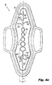
- the longitudinally extending channels 25, 26 are interconnected in the direction of (and, optionally, along or substantially along) the longitudinally extending centerline at nodes 27 1 through 27 n , where n is 1 (optionally 2 or greater, optionally from 2 to 100 , optionally from 3 to 20) as illustrated in Figs. 2 and 4b so as to form repeating, consistently or variably (including ascending and/or descending) sized, interconnected and longitudinally running shapes including, but not limited to, spherical shapes such as circles or ovals as shown in Figs. 2 and 4c , box-shaped (i.e., resembling a box in rectangularity) shapes as shown in Figs.
- the longitudinally extending channels 25, 26 define at least one (optionally, at least two, optionally at least three, optionally 2 to 30, optionally 3 to 6) substantially non-embossed (or non-compressed) area(s) 28, the non-embossed area(s) 28 (see Fig. 3 ) is located within central longitudinal zone 8 and does not extend beyond the central longitudinal zone width W.
- the longitudinally extending channels 25 and 26 are arranged symmetrically and equidistant with respect to the longitudinally extending centerline 1.
- substantially non-embossed as used herein with respect to the area defined by the longitudinally extending channels means greater than from about 55% to about 100%, optionally from about 75% to about 100% of the area is non-embossed (or non-compressed).
- longitudinally extending channel segments 25 1 , 25 2 and 25 3 are positioned opposite corresponding longitudinally extending channel segments 26 1 , 26 2 and 26 3 , respectively.
- Longitudinally extending channel segments 25 1 , 25 2 and 25 3 intersect corresponding longitudinally extending channel segments 26 1 , 26 2 and 26 3 at nodes 27 1 through 27 n (optionally 2 or greater, optionally from 2 to 100 , optionally from 3 to 20).
- the longitudinally extending channel segments 25 1 , 25 2 and 25 3 and corresponding longitudinally extending channel segments 26 1 , 26 2 and 26 3 are arranged, respectively, symmetrically and equidistant with respect to the longitudinally extending centerline 1.
- longitudinally extending channel segments 25 1 , 25 2 and 25 3 and corresponding longitudinally extending channel segments 26 1 , 26 2 and 26 3 are concave with respect to the longitudinal extending center line 1.
- each one of the longitudinally extending channel segments, 25 1 , 25 2 and 25 3 and corresponding longitudinally extending channel segments 26 1 , 26 2 and 26 3 has a length in the range of about 3 cm to about 15 cm, optionally from about 4.5 cm to about 10 cm, when measured along a path of the longitudinally extending channel segments between nodes 27.
- each of longitudinally extending channel segments 25 1 , 25 2 and 25 3 and 26 1 , 26 2 and 26 3 has a width in the range of from about 1 mm to about 20 mm, optionally from about 2 mm to about 10 mm.
- each of the longitudinally extending channel segments 25 1 , 25 2 and 25 3 and 26 1 , 26 2 and 26 3 has a thickness in the range of from about 1 mm to about 10 mm, optionally between about 2 mm and about 5 mm, when measured from a top surface of the absorbent article 20 at the longitudinally extending channel segment.
- the length of the central embossing pattern ranges from 55 mm to 200 mm (or from about 33 % to about 50 % of the longest length from the first transverse edge 15 to the second transverse edge 16).
- the central embossing pattern 23 can take the form of the central embossing patterns 23a, 23b, 23c, 23d and 23e as illustrated, respectively, at Figs. 4a to 4e .
- the central embossing pattern 23 interconnects in fluid communication with the first and second end embossing patterns 21, 22, respectively (e.g., at the first transverse side 4 and the second transverse side 5, respectively or, alternatively, at the intersection 29 of first transverse side 4 and the longitudinally extending centerline 1 and intersection 30 of second transverse side 5 and the longitudinally extending centerline 1, respectively).
- the respective ends of the longitudinally extending channels interconnect in fluid communication at the first transverse side 4 and the second transverse side 5 (or at intersections 29, 30) with at least one (optionally 2 to 10, optionally 3 to 8, optionally 4-6) of the plurality of channels 21a and/or 22a, respectively, with at least one (optionally 2 to 10, optionally 3 to 8, optionally 4-6) of the first and second longitudinally extending channels 21a' and/or 22a' (i.e., along the longitudinally extending centerline 1), respectively, or (directly or indirectly) with at least one (optionally 2 to 10, optionally 3 to 8, optionally 4-6) of the first and second branches 21a" and/or 22a"of the first and second end embossing patterns 21, 22, respectively.
- the fluid communicating interconnection of channels 25 and 26, at the first transverse sides 4, 5 (or at intersections 29, 30), with the first and second end embossing patterns 21, 22 in both the first and second longitudinal end regions 9, 10, respectively, enables the absorbent article 20 to effectively and simultaneously wick fluid from the central region 3 of the absorbent article 20 to both the first and second longitudinal rend regions 9 and 10, respectively. In this manner, the full absorbent capacity of the absorbent article 20 is utilized.
- the "channels" of the first and second end embossing patterns 21, 22, including the first and second plurality of channels 21a, 22a, the first and second longitudinally extending channels 21a', 22a' of the first and second plurality of channels 21 a, 22a, and the first and second branches 21 a", 22a" can, independently, be in the form of a straight channels or channels which are arcuate in shape (or in a combination of such shapes) and have a length in the range of about 2 cm to about 10 cm, optionally from about 5.0 cm to about 8.0 cm, when measured from the end of the such "channel” to the nearest of: i) the longitudinally extending channel 21a' or 22a' or ii) the initial node 27 1 or ending node 27 n , respectively, along the path of such channel.
- such "channels” have a width in the range of from about 1 mm to about 10 mm, optionally from about 2 mm to about 4.0 mm. In certain embodiments, the "channels" have a thickness of about 0.5 mm to about 2.5 mm, optionally about 1 mm to about 2 mm, when measured from a top surface of the absorbent article 20 at such channel. In certain embodiments, the first and second longitudinal extending channels 21 a', 22a' of the first and second end embossing patterns 21, 22 do not extend outside the central longitudinal zone 8. In certain embodiments, the first and second branches 21 a", 22a" extend outside the central longitudinal zone 8.
- the "channels" and “branches” of the first and second end embossing patterns 21, 22 function to transport fluid towards the longitudinal end regions 3, 4 of the absorbent article 20 to thereby utilize the full absorbent capacity of the article along its length.
- the absorbent article of the present invention further includes an outer embossing pattern as illustrated in one embodiment by outer embossing pattern 24.
- the outer embossing pattern 24 comprises one or more (optionally, two or more) first and one or more (optionally, two or more) second longitudinally extending outer channels 24a, 24b, respectively, which one or more first and one or more second longitudinally extending outer channels 24a, 24b are independently shaped and oppositely positioned with respect to one another and at least partially separated by the central longitudinal zone 8.
- Each longitudinally extending outer channel 24a or 24b extends longitudinally at least partially across each of central longitudinal zone edges 8a and 8b and is spaced from 5 (or about 5) mm to 26 (or about 26) mm, optionally 10 (or about 10) mm to 20 (or about 20) mm, from the nearest central longitudinal zone edge 8a or 8b.
- the first and second longitudinally extending outer channels 24a, 24b can be the same or different in shape (or configuration).
- the one or more first longitudinally extending outer channels 24a are parallel to each other and, optionally, the one or more second longitudinally extending outer channels 24b are parallel to each other.
- the longitudinally extending outer channels 24a, 24b are substantially equal in length to the length of the central region 3 shown in Figs. 1 and 2 .
- the respective ends of each of longitudinally extending outer channels 24a, 24b are extended so as to unite the respective ends of the other longitudinally extending outer channels (in fluid communication) such that the outer embossing pattern 24 surrounds or substantially surrounds the central embossing pattern and the first and second end embossing patterns as shown in Figs. 3 , 4a to 4d and 5.
- the longitudinally extending outer channels 24a, 24b are deep stitched or comprise a "dotted" pattern.
- the longitudinally extending outer channels 24a, 24b have a width of from about 1 mm to about 10 mm and a thickness of from about 0.5 mm to about 2.5 mm, when measured from a top surface of the absorbent article 20 at longitudinally extending outer channel 24a, 24b.
- the absorbent article of present invention incorporating into the absorbent article of present invention the central embossing pattern, the first and second end embossing patterns and the outer embossing patterns , these embossing patterns cooperate so as to result in the absorbent article 20 having improved frequency of hump deformation.
- the absorbent article will deform into the shape of a hump at a frequency of from about 75%, optionally about 90%, or optionally about 95%, to about 98%, optionally about 99%, or optionally about 100%, of such use related deformations (or simulated deformation, when measured by the Deformation/Distribution Test described below), resulting in the article conforming to and being in close contact with the user's body Fig. 12 .
- the central embossing pattern comprises two longitudinally extending channels 25 and 26, each extending the length of the central embossing pattern so as to only interconnect at the first transverse sides 4, 5 (or at intersections 29, 30).
- longitudinally extending channels 25 and 26 further interconnect at one or more nodes 27.
- channels 25 1 and 25 2 and 26 1 and 26 2 are connected at nodes 27 (1-n) .
- the second (or central region) embossing pattern 40 having an outer embossed or compressed border 41 defining at least one (optionally, at least two, optionally at least three, optionally 2 to 30, optionally 3 to 6) substantially embossed (or compressed) area 42, the embossing pattern 40, including embossed area 42, located within central longitudinal zone and do not extend beyond central longitudinal zone width W.
- the area defined by outer embossed (or compressed) border 41 is similar in size and shape as the pattern of the central embossing pattern 23 of Fig. 1 .
- substantially embossed as used herein with respect to the area defined by the outer embossed (or compressed) border 41 means greater than from about 55% to about 100%, optionally from about 75% to about 100% of the area is embossed.
- the absorbent article may include a cover layer, a transfer layer, a core, a barrier layer and combinations thereof.
- the embossing patterns and channels are formed using conventional embossing techniques.
- the embossing roll used during manufacture should have surface features used to form the first, second and third embossing patterns.
- the embossing patterns result in areas of increased density.
- the central area of the absorbent article includes from about 10% to about 50% areas of increased density.
- the channels of the absorbent article may be provided with color, to thereby provide a color cue that is visible to a user from a top surface of the absorbent article.
- the color cue may be provided by printing colored regions to the cover layer.
- the colored regions optionally correspond in size, shape and location to the channels.
- the colored regions function to provide the user with a color cue to the presence and function of the channels.
- the colored regions could alternatively be printed on the absorbent layer provided that such colored regions can be viewed through the cover. Any means known to those of skill in the art may be utilized to provide the colored regions such as printing, utilizing colored fibers, or any other suitable means.
- Absorbent articles according to the invention have a thickness that may range from about 2 mm to about 20 mm in an uncompressed state. Where the absorbent article is compressed as a result of the embossing patterns described and utilized in the present invention, the thickness of the embossed area (or channels) may be measured with a Mitutoyo 547-516 thickness gauge or the like. For absorbent articles having an uncompressed thickness greater than 4 mm, the compressed thickness, unless otherwise specified herein, may range from about 0.5 mm (highly densified channel) to about 2.5 mm (lightly densified channel). For absorbent articles having an uncompressed thickness less than 4 mm, the compressed thickness may range from about 0.25 mm to about 2.0 mm.
- the absorbent article is embossed (or compressed) and the thickness reduced in at least one layer but, optionally, in or through multiple layers or, optionally, in or through all the layers of the absorbent article.
- thicker materials will undergo more thickness reduction. Accordingly, the layers which are actually embossed will, among other things, depend on the manufacturing process (e.g., which material is joined at the point where the embossing is applied).
- the embossing can be achieved with standard techniques such as thermal bond, ultrasonic bond and/or pressure.
- An example of a suitable process is thermal bonding wherein the layers are passed through two steel rolls where one is engraved with the visual pattern and the other is flat.
- one or both of the rolls are warmed to temperature suitable to at least partially melt one or more layer (typical range from 90 to 170°C).
- the embossing roll may be engraved using conventional techniques such machine tooling for most embossing patterns, but it may be desirable to use acid etching or laser engraving to provide a finer engraving, and thus a finer embossed pattern. It may be desirable that the embossed pattern comprises relatively thin embossing features, much thinner than the embossed channels previously disclosed in the art, such as in U.S. Pat. Pub. No. 20040015145A1 to Miura et al. , which publication is herein incorporated by reference. Thin embossing features may provide a generally feminine and delicate look to the article.
- the embossing tool should therefore capable of high definition embossing, in particular with a resolution (minimum thickness of the embossed lines) of less than about 0.75 mm, in particular but not limited to between about 0.35 mm and about 0.60 mm.
- Embossing of this type is often in the form of a plurality of lines where the product is embossed along the entire length of the lines.
- a second type of embossing that may be used is deep stitch embossing where a series of spots are embossed along a linear pattern. This type of embossing gives a can give a stitched appearance similar to sewn garments and fabrics.
- An example of this type of embossing is used in Whisper Choice napkins marketed by Proctor and Gamble Healthcare ltd, India.
- the embossing (or embossing patterns) of the absorbent articles of the present invention cooperate to produce the controlled deformation of the disclosed article.
- Such controlled deformation is achieved i) without the use of tensioned elastic materials as described in US Pat. No. 4,911,701 to Mavinkurve , the specific disclosure of which materials is found in Figs. 1-6 and at col. 3, line 10 to col. 4, line 3 and is herein incorporated by reference; in addition to the foregoing, the remainder of US Pat. No. 4,911,701 is also herein incorporated by reference; the flexure-resistant deformation element described in US Pat. No. 5,171,302 to Buell , the specific disclosure of which materials is found in Figs. 1-27 and at col.
- the absorbent articles of the present invention is free of non-embossing deformation causing materials or elements which are not embossing or embossing patterns.
- the cover layer may be a relatively low density, bulky, high-loft non-woven web material.
- the cover layer may be composed of only one type of fiber, such as polyester or polypropylene or it may include a mixture of more than one fiber.
- the cover may be composed of bi-component or conjugate fibers having a low melting point component and a high melting point component.
- the fibers may be selected from a variety of natural and synthetic materials such as nylon, polyester, rayon (in combination with other fibers), cotton, acrylic fiber and the like and combinations thereof.
- the cover layer has a basis weight in the range of about 10 gsm to about 75 gsm.
- Bi-component fibers may be made up of a polyester layer and a polyethylene sheath.
- the use of appropriate bi-component materials results in a fusible non-woven fabric. Examples of such fusible fabrics are described in U.S. Pat. No. 4,555,430 to Mays , which patent is herein incorporated by reference. Using a fusible fabric increases the ease with which the cover layer may be mounted to the absorbent layer and/or to the barrier layer.
- the cover layer optionally has a relatively high degree of wettability, although the individual fibers comprising the cover may not be particularly hydrophilic.
- the cover material should also contain a great number of relatively large pores. This is because the cover layer is intended to take-up body fluid rapidly and transport it away from the body and the point of deposition. Therefore, the cover layer contributes little to the time taken for the absorbent article to absorb a given quantity of liquid (penetration time).
- the fibers which make up the cover layer should not lose their physical properties when they are wetted, in other words they should not collapse or lose their resiliency when subjected to water or body fluid.
- the cover layer may be treated to allow fluid to pass through it readily.
- the cover layer also functions to transfer the fluid quickly to the underlying layers of the absorbent article.
- the cover layer is advantageously wettable, hydrophilic and porous.
- the cover layer may be treated with a surfactant to impart the desired degree of wettability.
- the cover layer can also be made of polymer film having large pores. Because of such high porosity, the film accomplishes the function of quickly transferring body fluid to the inner layers of the underlying absorbent layers.
- a suitable cover material of this type is commercially found on the STAYFREE Dry Max Ultrathin product distributed by McNeil-PPC, Inc.
- the cover layer may be attached to the underlying absorbent layers and/or the barrier layer, by adhesion and/or other suitable means know to those of skill in the art.
- the absorbent layer may be composed of fibrous materials, such as wood pulp, polyester, rayon, flexible foam, or the like, or combinations thereof.
- the absorbent layer may also optionally include a superabsorbent polymer (SAP) material.
- SAP superabsorbent polymer
- the absorbent layer may also comprise thermoplastic fibers for the purpose of stabilizing the layer and maintaining its structural integrity.
- the absorbent layer may be treated with surfactant on one or both sides in order to increase its wettability, although generally the absorbent layer is relatively hydrophilic and may not require treatment.
- the absorbent layer is optionally bonded on both sides to the adjacent layers, i.e. the cover layer and underlying second absorbent layer or barrier layer.
- the absorbent layer may be a "transfer" layer.
- the transfer layer provides means for receiving body fluid from the fluid-pervious cover layer and holding it until a second absorbent layer has an opportunity to absorb it.
- the transfer layer is, optionally, more dense than the fluid-pervious cover layer and has a larger proportion of smaller pores than does the latter. These attributes allow the transfer layer to contain body fluid and hold it away from the outer side of the fluid-pervious cover layer, thereby preventing the fluid from re-wetting the fluid-pervious cover layer and its surface.
- the transfer layer is optionally not so dense as to prevent the passage of the fluid through the transfer layer and into the underlying second absorbent layer.
- the first absorbent layer may comprise various materials, including, for example, cellulose fibers such as from wood pulp, single component or bicomponent fibers that include thermoplastic materials (such as polyester, polypropylene, polyethylene, among others) in fiber or other forms, rayon, organic binders (such as copolymers of vinyl, acrylic and/or other monomers that may be coated onto thermoplastic fibers or otherwise incorporated into the transfer layer) among other materials known to the art.
- cellulose fibers such as from wood pulp, single component or bicomponent fibers that include thermoplastic materials (such as polyester, polypropylene, polyethylene, among others) in fiber or other forms, rayon, organic binders (such as copolymers of vinyl, acrylic and/or other monomers that may be coated onto thermoplastic fibers or otherwise incorporated into the transfer layer) among other materials known to the art.
- the absorbent article of the present invention may comprise one or more absorbent layers.
- the second or any additional absorbent layers may comprise a single layer of material or may comprise multiple layers.
- the second absorbent layer functions as the absorbent core of the absorbent article.
- such absorbent core has a high total absorbent capacity and function to hold fluid upon receiving such fluid from the transfer layer.
- the absorbent core optionally has a greater density than that of the transfer layer.
- the second absorbent layer is a blend or mixture of cellulosic fibers and superabsorbent disposed therein.
- Cellulosic fibers that can be used in the second absorbent layer are well known in the art and include wood pulp, cotton, flax and peat moss.
- wood pulp is used in the second absorbent layer. Pulps can be obtained from mechanical or chemi-mechanical, sulfite, kraft, pulping reject materials, organic solvent pulps, etc. Both softwood and hardwood species are useful.
- softwood pulp is used in the second absorbent layer. It is not necessary to treat cellulosic fibers with chemical debonding agents, cross-linking agents and the like for use in the present material.
- Some portion of the pulp may be chemically treated as discussed in U.S. Pat. No. 5,916,670 to Tan et al. , herein incorporated by reference, to improve flexibility of the product. Flexibility of the material may also be improved by mechanically working the material or tenderizing the material.
- the second absorbent layer can contain any superabsorbent polymer (SAP) which are well known in the art.
- SAP superabsorbent polymer
- the superabsorbent polymer particles of the invention may be inorganic or organic crosslinked hydrophilic polymers, such as polyvinyl alcohols, polyethylene oxides, crosslinked starches, guar gum, xanthan gum, and the like.
- the particles may be in the form of a powder, grains, granules, or fibers.
- the superabsorbent polymer particles are crosslinked polyacrylates, such as the product offered by Sumitomo Seika Chemicals Co., Ltd. Of Osaka, Japan, under the designation of SA70N and products offered by Stockhausen Inc.
- the second absorbent layer is a material containing from 90% to about 40% percent cellulosic fiber, and about 10% to about 60% SAP.
- the second absorbent layer may comprise a material manufactured by using air-laying means well known in the art.
- a barrier layer comprising liquid-impervious film material so as to prevent liquid that is entrapped in the absorbent layer from egressing the absorbent article and staining the wearer's undergarment.
- the barrier layer is optionally made of polymeric film, although it may be made of liquid impervious, air-permeable material such as repellent-treated non-woven or micropore films or foams.
- the barrier layer may be breathable, i.e., permits vapor to transpire.
- Known materials for this purpose include nonwoven materials and microporous films in which microporosity is created by, inter alia, stretching an oriented film.
- Single or multiple layers of permeable films, fabrics, melt-blown materials, and combinations thereof that provide a tortuous path, and/or whose surface characteristics provide a liquid surface repellent to the penetration of liquids may also be used to provide a breathable backsheet.
- the cover layer and the barrier layer are optionally joined along their marginal portions so as to form an enclosure or flange seal that maintains the absorbent layers and captive.
- the joint may be made by means of adhesives, heat-bonding, ultrasonic bonding, radio frequency sealing, mechanical crimping, and the like and combinations thereof.
- Positioning adhesive may be applied to a garment facing surface of the barrier layer for securing the absorbent article to a garment during use.
- the positioning adhesive may be covered with removable release paper so that the positioning adhesive is covered by the removable release paper prior to use.
- Absorbent articles of this invention may or may not include wings 200 (or, alternatively, flaps or tabs) for securing the absorbent article to an undergarment.
- Wings also called, among other things, flaps or tabs, and their use in sanitary protection articles is described in U.S. Pat. No. 4,687,478 to Van Tilburg ; U.S. Pat. No. 4,589,876 also to Van Tilburg , U.S. Pat. No. 4,900,320 to McCoy , and U.S. Pat. No. 4,608,047 to Mattingly .
- the disclosures of each of these patents are herein incorporated by reference.
- wings 200 are generally speaking flexible and configured to be folded over the edges of the underwear so that the wings 200 are disposed between the edges of the underwear.
- any of the above described layers, optionally the cover and/or barrier layers may be micro-embossed, have a printed design, have a printed message to the consumer, and/or may be at least partially colored.
- the Deformation and Distribution Test simulates how the absorbent article will deform and, at the same time, function to distribute fluid under realistic wearing conditions.
- the deformed shape of the absorbent article influences where fluid exiting the body contacts the absorbent article.
- the absorbent structure (and any embossing contained on the body facing surface thereof) will affect how it is distributed from contact onward.
- fluid is concentrated along the longitudinal center line of the absorbent article and as more fluid contacts the article, the fluid spreads primarily along the length of the absorbent article, maintaining a distance from the edges of the absorbent article.
- Absorbent articles resulting in this type of fluid contact and distribution give the consumer confidence that leakage will not occur.
- the device 150 used in performing the Deformation/Distribution Test is depicted in Figs. 6 to 8 and is a modified version the device described in US Pat. No. 5,607,414 to Richards et al. , which patent is herein incorporated by reference.
- the support blocks 10 have curved surfaces as shown in Figs. 6 with a radius of curvature equal to 92 mm.
- the longitudinal distance (along x axis) between points 50a and 50b of the support blocks 10, shown in Fig. 6 is 77 mm. At points 50a and 50b, the tangent to the curved surfaces is parallel to the horizontal plane.
- the edge 60 of support blocks 10 has a width of 80 mm.
- the edge 70 of support blocks 10 has a length of 105mm.
- the edge 80 of support blocks 10 has a height of 75mm.
- the compression plates 30 have a length of 70mm measured along the compression plates 30 in the direction from point 50a to point 50b (along x axis parallel to edge 70) and have a radius of 224mm measured with respect to the vertical axis z' of Fig. 6 .
- the compression plates have a width of 34 mm in the direction of the vertical axis z.
- the support blocks 10 are fixedly secured on a base plate 90 having a thickness of 12 mm. Points 50a and 50b are about 5 mm above the upper surface of the base plate 90. The bottom surfaces of the compression plates 30 are coplanar with the upper surface of the base plate 90.
- the base plate has a 90 mm long by 77 mm wide through cut out area 110 extending between the two support blocks.
- a panty 300 as described below is cut at each hip section so that it can be laid flat as shown in Fig. 7 .
- Strips of double stick tape 400 are placed on the two test support blocks 10 in regions 100 (region 100 is depicted as the region between the dashed lines on the curved surfaces of blocks 10 in Fig. 6 ).
- the adhesive type 400 is Tectape, code 633, supplied by Day Brasil.
- the adhesive tape regions 100 are each 65 mm wide in the direction of edge 60 and cover the entire curved surface of the support blocks in the direction perpendicular to edge 60.
- the cut garment is then laid onto the two supports such that the crotch bridges the region between the support blocks 10 as shown in Fig. 7 .
- the panty 300 is placed so that there is no significant tension in the fabric but it also has no slack.
- the panty is also placed so that there is no wrinkling or stretching of the garment in the adhesive tape regions 100.
- the narrowest section of the crotch section is centered between the support blocks 10.
- each support block has a clamp 120 to aid in holding down the garment.
- a test article sample is prepared by removing an absorbent article product from its packaging and removing any other release papers from the product.
- the article sample is placed on the support blocks 10 so that the entire area of the article sample's central positioning adhesive sticks to the panty 300.
- Wings 200 of the article sample are wrapped around and stuck to the backside of the panty (i.e., the side of the panty facing the device). It is critical to avoid deforming the central region 3 of the absorbent core of the article sample while placing it on the support and wrapping and sticking the wings 200 to the backside side of the panty.
- Wrapping of the wings 200 around the panty is performed so that the each wing is wrapped as far as possible on the backside of the panty 300 such that the panty is not gathered or deformed. Finger pressure is applied to insure the wing 200 is adhered to the backside of the panty 300.
- the compression plates 30 of the device 150 are positioned at a starting distance (or first position) of 65 mm from each other.
- the compression plates 30 are compressed (or moved) together at a speed of 15mm/sec until they are separated from each other by 25mm (or second position), the compression plates 30 are, then, moved apart at a speed of 15mm/sec until they are again separated from each other by 65mm (first position).
- the specified distances 25 and 65 mm are based on the nearest points on the compression plates facing article sample 20 and panty 300 once the article and panty are positioned on the device for testing.
- compression (or movement) of compression plates 30 is accomplished by pneumatic cylinders; however, other compression driving mechanisms capable of providing the above compression and return movements may optionally be used such as servo motors.
- a control box (130) may be mounted on the apparatus for actuating test and controlling test parameters (e.g., number of test cycles and test cycle speeds).
- the article sample is held in the compressed (or deformed) state (i.e., not returned to its starting position) and the deformation is visually inspected to determine formation of either a "hump", "cup” or "bunch” configuration.
- the above described procedure is repeated 10 times on separate test article samples.
- the occurrence of "hump", "cup” or “bunch” is recorded at the end of each test procedure.
- the percentage of procedures resulting in a "hump” deformation occurrence is calculated.
- the articles of the present invention deform into a hump deformation in at least about 75%, optionally, at least about 80%, optionally, at least about 85%, optionally, at least about 90%, optionally, at least about 95% of such repeated procedures.
- the article sample is held in the compressed (or deformed) state and the ability of the article sample to wick and distribute fluid along the longitudinal centerline os article sample is assessed as follows:
- panty used for this test is constructed from woven cotton fabric with elastic leg bands supplied by Marisa in Brazil (supplier code 29771). This type fabric and construction is available in panties in most regions.
- the crotch of the panty at its narrowest point has a width of between 60 and 70 mm. Certain panties have a section with double layer fabric in the center. At a distance of 50 mm forward and rear of the narrowest point, the panty will have a width between 70 and 80 mm.
- Tenabsorbent article samples were prepared using a 15 gsm polypropylene spunbond nonwoven (Spunbond 15) supplied by Polystar, Brazil as the cover layer; 415 gsm cellulose fluff pulp (Grade 4881) supplied by Georgia Pacific, USA as the absorbent layer; and 21 gsm polyethylene film (PE 21) supplied by Clopay, Brazil as the barrier layer.
- the embossing patterns of Fig. 3 was applied to the regions of absorbent articles as described above with an embossing thickness ranging from 2 mm to 3 mm, when measured from a top surface of the absorbent article at the embossing.
- the absorbent article samples were tested for hump deformation and longitudinal fluid wicking using the Deformation/Distribution Test method described above.
- absorbent articles according to the present invention provide a structure that enables such article to provide superior wicking characteristics and controlled deformation.
Abstract
Description
- The present application claims the benefit of the earlier filing date of United States provisional patent application
62/057,690, filed September 30, 2014 - The present invention generally relates to absorbent articles and in particular to absorbent articles demonstrating controlled deformation and enhanced fluid wicking or distribution in the longitudinal direction of the absorbent articles.
- In order for absorbent articles, such as sanitary napkins, to efficiently absorb a large amount of fluid during use it should effectively wick fluid throughout the absorbent structure of the absorbent article. Absent effective wicking properties, fluid such as menstrual fluid tends to pool in certain regions of the absorbent article. As a result, the full absorbent capacity of the absorbent article is not effectively utilized.
- In addition to having effective wicking capabilities, such absorbent articles should also quickly or rapidly absorb fluid.
- Under such circumstances (namely an article exhibiting effective wicking and rapid fluid absorption properties), the closer such an absorbent article is to the body, the faster it will absorb fluid exiting the body.
- Accordingly, the inventors of the present invention have recognized a need for ide absorbent articles that comfortably and efficiently wick fluid in the longitudinal direction of the absorbent article while at the same time deforms into a hump for closer positioning to a user's body (i.e., the crotch or vaginal area).
- Therefore, an aspect of the present invention is to provide an absorbent article which provides improved fluid wicking and at the same time, once deformed, exhibits a controlled deformation such that the absorbent article results in a hump deformation at a frequency of at least 75% of such deformations.
- In certain embodiments, the present invention relates to an absorbent article having a transversely extending centerline and a longitudinally extending centerline and a body facing surface, the body facing surface comprising:
- a central region having i) a first transverse side parallel to the transversely extending centerline and a second transverse side parallel to the transversely extending centerline and opposite the first transverse side in the direction of the longitudinally extending centerline; and ii) a first longitudinal side parallel to the longitudinally extending centerline and a second longitudinal side parallel to the longitudinally extending centerline and opposite the first longitudinal side in the direction of the transversely extending centerline, the central region comprising an embossing pattern comprising at least two longitudinally extending channels having respective ends thereof and interconnecting with each other, other than at their respective ends (or, optionally, at one or more points between their respective ends, or, optionally, at one or more points between the first and second transverse sides), to define at least one substantially embossed region;
- a first longitudinal end region extending from the first transverse side of the central region directionally along the longitudinally extending centerline away from the central region, the first longitudinal end region comprising a first plurality of channels wherein at least one of the channels of the first plurality of channels extends directionally along a longitudinally extending centerline from the first transverse side across from about 50% to about 90% of the first longitudinal end region;
- a second longitudinal end region extending from the second transverse side of the central region directionally along the longitudinally extending centerline and away from the of the central region, the second longitudinal end region comprising a second plurality of channels wherein at least one of the channels of the second plurality of channles extends directionally along a longitudinally extending centerline from the second transverse side across from about 50% to about 90% of the second longitudinal end region, the embossing pattern of the central region located longitudinally between and interconnected with the first and second plurality of channels at the respective ends of the at least two longitudinally extending channels of the embossing pattern of the central region;
- a central longitudinal zone extending longitudinally across the first and second transverse end regions and the central region, the central longitudinal zone extending symmetrical about and directionally along the longitudinally extending centerline and comprising opposing longitudinally extending central longitudinal zone edges parallel to the longitudinally extending centerline defining a central longitudinal zone width W of from about 5 mm to about 20 mm, wherein the embossing pattern of the central region is located within the central longitudinal zone and does not extend beyond the central longitudinal zone width W;
- a first transverse end region extending from the first longitudinal side of the central region directionally along the transversely extending centerline and away from the central region, the first transverse end region comprising a least one first longitudinally extending outer channel spaced from about 5 mm to about 26 mm from the nearest central longitudinal zone edge; and
- a second transverse end region extending from the second longitudinal side of the central region directionally along the transversely extending centerline and away from the of the central region, the second transverse end region comprising a least one second longitudinally extending outer channel spaced from about 5 mm to about 26 mm from the nearest central longitudinal zone edge
- wherein the embossing pattern of the central region interconnects in fluid communication with the embossing patterns of the first and second longitudinal end regions.
- In certain embodiments, the present invention relates to an absorbent article comprising:
- a longitudinally extending centerline;
- a transversely extending centerline;
- a first longitudinal end region;
- a second longitudinal end region;
- a central region arranged between the first and second longitudinal end regions;
- a body facing surface comprising:
- a central longitudinal zone which extends from one end of the article to the other end of the article directionally along and symmetrically about the longitudinally extending centerline, the central longitudinal zone comprising opposing longitudinally extending zone edges defining a central longitudinal zone width W of from about 5 mm to about 20 mm and wherein the central longitudinal zone width W is symmetrical about the longitudinally extending centerline;
- first and second end embossing patterns, each of the first and second end embossing patterns located in each of the first and second longitudinal end regions, respectively, the first and second end embossing patterns comprising, respectively and independently, a first and second plurality of branched channels wherein at least one of each of the first and second plurality of branched channels extends longitudinally within and not extending beyond the central longitudinal zone across from about 50% to about 90% of the first and second end regions, respectively;
- a central embossing pattern within the central longitudinal zone and not extending beyond to the central longitudinal zone width W, the central embossing pattern located in the central region and comprising at least two longitudinally extending channels having respective ends thereof extending in the direction of the longitudinally extending centerline to interconnect, at their respective ends, with the first and second plurality of branched channels, the longitudinally extending channels further interconnecting with each other, other than at their ends, to define at least one substantially embossed region ; and
- an outer embossing pattern comprising at least two longitudinally extending outer channels, the longitudinally extending outer channels positioned opposite one another and at least partially separated by the central longitudinal zone, wherein each longitudinally extending outer channel is spaced from about 5 mm to about 26 mm from the nearest zone central longitudinal zone edge;
- wherein the central embossing pattern interconnects in fluid communication with the first and second end embossing patterns of the first and second longitudinal end regions to facilitate fluid flow longitudinally across the article; and
- Examples of embodiments of the present invention will now be described with reference to the drawings, in which:
-
FIG. 1 is a top view of an embodiment of the embossing patterns of the articles of the present invention. -
FIG. 2 is a top view of an embodiment of the embossing patterns of the articles of the present invention. -
FIG. 3 is a top view of an embodiment of the embossing patterns of the articles of the present invention. -
FIGS. 4a to 4e are top views of various embodiments of the embossing patterns of the central and longitudinal end regions of the articles of the present invention. -
FIG. 5 is a top view of an embodiment of the embossing patterns of the articles of the present invention, illustrating embossedregion 42. -
FIG. 6 is a perspective view of the deformation and fluiddistribution testing device 150 andpanty 300 for placement ontodevice 150 prior to testing. -
FIG 7 is a perspective view of the deformation and fluid distribution testing device, showing placement of thepanty 300 and positioning ofarticle 20 for placement in preparation for testing. -
FIG. 8 is a perspective view of the deformation and fluiddistribution testing device 150 in operation. -
FIG. 9 is a cross-sectional view of the deformation and fluiddistribution testing device 150 in operation taken along line 9-9 inFIG. 8 , showing hump deformation as movement away from x, y plane ofFIG. 8 upward in the direction of the z axis. -
FIG. 10 is a cross sectional view of an absorbent article forming a type of a hump deformation along the longitudinal centerline. -
FIG. 11 is a cross sectional view of an absorbent article forming a type of a hump deformation along the longitudinal centerline. -
FIG. 12 is a cross sectional view of an absorbent article forming a type of a hump deformation along the longitudinal centerline. -
FIG. 13 is a cross sectional view of an absorbent article forming a type of a hump deformation along the longitudinal centerline. -
FIG. 14 is a cross sectional view of an absorbent article forming a type of a hump deformation along the longitudinal centerline. -
FIG. 15 is a cross sectional view of an absorbent article forming a type of a cup deformation along the longitudinal centerline. -
FIG. 16 is a cross sectional view of an absorbent article forming a type of a cup deformation along the longitudinal centerline. -
FIG. 17 is a cross sectional view of an absorbent article forming a type of a cup deformation along the longitudinal centerline. -
FIG. 18 is a cross sectional view of an absorbent article forming a type of a cup deformation along the longitudinal centerline. -
FIG. 19 is a cross sectional view of an absorbent article forming a type of a cup deformation along the longitudinal centerline. -
FIG. 20 is a cross sectional view of an absorbent article forming a hump deformation for positioning the absorbent article closer to a user during use. - The articles of the present invention can comprise, consist of, or consist essentially of the essential elements and limitations of the invention described herein, as well any of the additional or optional features, components, or limitations described herein.
- The term "comprising" (and its grammatical variations) as used herein is used in the inclusive sense of (and, interchangeably with the terms) "having" or "including" and not in the exclusive sense of "consisting only of." The terms "a" and "the" as used herein are understood to encompass the plural as well as the singular.
- All documents incorporated herein by reference are only incorporated herein to the extent that they are not inconsistent with this specification.
- All percentages, parts and ratios are based upon the total weight of the article of the present invention, unless otherwise specified.
- In certain embodiments, the present invention as disclosed herein may be practiced in the absence of any compound, component or element (or group of compounds, components or elements) which is not specifically disclosed herein.
- As used herein the term "controlled deformation" means deformation of an absorbent article which is controlled by the structure of the absorbent article, including any embossing features and/or patterns, in such a way that upon application of deformation forces (e.g., as generated when an absorbent article [e.g., sanitary napkin] is applied to and against the crotch of a user), the absorbent article predictably deforms into a hump so as to generally remain in contact with the crotch or vaginal area of the user.
- As used herein, the term "hump" represents a configuration, upon visual inspection, of the absorbent article where, upon compression using the
device 150 used in performing the Deformation/Distribution Test described below, the central longitudinal zone 8 (as defined below herein) has risen vertically (in the positive direction of vertical axis z) along the longitudinally extending centerline 1 relative to (i.e., so as to be above) the portions (301a, 302a) of longitudinally extending regions (301, 302) that are nearest to the central longitudinal zone 8 (as illustrated inFigs. 10-14 ), where longitudinally extendingregion 301 extends transversely away from longitudinally extendingzone edge 8a across the length of the article and longitudinally extendingregion 302 extends transversely away from longitudinally extendingzone edge 8b,across the length of the article in a direction opposite the direction of longitudinally extendingregion 301. - As used herein, the term "cup" represents a configuration, upon visual inspection, of the absorbent article where, upon compression using the
device 150 used in performing the Deformation/Distribution Test described below, the central longitudinal zone 8 (as defined below herein) has descended vertically (in the negative direction of vertical axis z) along the longitudinally extending centerline 1 relative to (i.e., so as to be below) the portions (301a, 302a) of longitudinally extending regions (301, 302) that are nearest to the central longitudinal zone 8 (as illustrated inFigs. 15-19 ). - As used herein, the term "bunch" represents a configuration, upon visual inspection, of the absorbent article where, upon compression using the
device 150 used in performing the Deformation/Distribution Test described below, neither a hump nor cup is formed. - As used herein, the term "visual inspection" or "visually inspected" means that a human viewer can visually discern the presence of the subject matter under such inspection with the unaided eye (excepting standard corrective lenses adapted to compensate for near-sightedness, farsightedness, or stigmatism, or other corrected vision) in lighting at least equal to the illumination of a standard 75 watt incandescent white light bulb at a distance of about 0.25 meter.
- One embodiment of an absorbent article according to the present invention is illustrated in
Fig. 1 . In certain embodiments, the absorbent article, as illustrated byarticle 20, has a length (measured as the longest length from the first transverse edge 15 to the second transverse edge 16) of from about 170 mm to about 400 mm and a width (measured as the longest length from the firstlongitudinal edge 13 to the second longitudinal edge 14) of from about 40 mm to about 80 mm. The outermost region 17 of theabsorbent article 20 represents the area in which the cover and barrier layers extend beyond the border edges of the absorbent core and, hence, does not include absorbent core; theregion 17 is not measured as part of (or otherwise taken into consideration when measuring) the length, width and/or surface area of the absorbent articles of the present invention. - As illustrated in
Fig. 1 , the absorbent article includes a longitudinally extending centerline 1, a transversely extendingcenterline 2, a firstlongitudinal edge 13, a secondlongitudinal edge 14, a first transverse edge 15, a secondtransverse edge 16, a first longitudinal end region 9, a secondlongitudinal end region 10, a central region 3 located between the first longitudinal end and second longitudinal end regions, 9 and 10 (the central region 3 contacting the first and secondlongitudinal end regions 9 and 10 at first and secondtransverse sides 4 and 5 of the central region 3, respectively) and a centrallongitudinal zone 8 which extends longitudinally from one end of the article, namely the first transverse edge 15, to the other end of the article, namely the secondtransverse edge 16 and has opposing longitudinally extendingzone edges - In some embodiments of the present invention (such as in
Fig. 1 ), thetransverse centerline 2 may be equidistant between the first transverse edge 15 and the secondtransverse edge 16. In other embodiments, the absorbent article may be asymmetric from front to back so that the end intended to be placed to the rear of the vaginal opening (i.e, nearer the backside of the user) may be longer than the end intended to be placed forward of the vaginal opening (i.e., nearer the front of the user). Examples of this type of product are Sempre Livre Noturno Toque Suave com Abas available from Johnson and Johnson Brasil and Always ultrathin overnight from Proctor and Gamble USA. In these products, the transverse centerline will intersect the center of thewings 200 or an area meant to be positioned directly over the vaginal opening. - In certain embodiments, the length of the first and second longitudinal end regions 9, 10 (as measured from the outer most longitudinally extending edge of first transverse edge 15 or second
transverse edge 16, respectively) ranges from about 30 mm to about 70 mm (or about 1/3 the longest length between the first transverse edge 15 and second transverse edge 16). In certain embodiments, the width of the first and second longitudinal end regions 9, 10 (measured as the longest length from the firstlongitudinal edge 13 to the secondlongitudinal edge 14 within the respective lengths of first or second longitudinal regions 9, 10) ranges from about 30 mm to about 70 mm. In certain embodiments, the length of the central region (measured as the length between the first and second longitudinal end regions 9, 10) ranges from about 55 mm to about 200 mm (about 1/3 to about ½ the longest length between the first transverse edge 15and second transverse edge 16). In certain embodiments, the width of the central region 3 is the total of widths a' and a" extending, oppositely from the longitudinal centerline 1, where widths a' and a" range, independently, from about 15 mm to about 35 mm. The width a' terminates at a first longitudinal side 6 of the central region 3 and width a" terminates at a second longitudinal side 7 of the central region 3 of the central region 3 as illustrated atFig. 1 . - The absorbent article includes first and second end embossing patterns located opposite one another in the first and second longitudinal end regions, respectively, as illustrated in
Fig. 2 in one embodiment by first and secondend embossing patterns longitudinal end regions 9, 10, respectively. Each of the first and secondend embossing patterns longitudinal end regions 9, 10, respectively, comprise, independently, a first and second plurality ofchannels channels Figs. 1 and4b (and portions ofFigs. 4a and4d ) or unbranched as inFig. 4c (or portions ofFigs. 4a , and4d ). As the firstend embossing pattern 21 is located within the first longitudinal end region 9 and secondend embossing pattern 22 located in the secondlongitudinal end region 10, the first plurality ofchannels 21 a of the firstend embossing pattern 21 are spaced from the second plurality ofchannels 22a of the secondend embossing pattern 22 in the longitudinal direction of longitudinally extending centerline 1. The first and second plurality ofchannels channels - The first and second plurality of
channels channel 21 a' (first longitudinally extending channels) and 22a' (second longitudinally extending channels) in the first and secondlongitudinal end regions 9, 10, respectively, each longitudinally extendingchannel 21a' and 22a' of the first and second plurality ofchannels longitudinal end regions 9, 10, respectively. - In certain embodiments, the channels of the first and second plurality of
channels longitudinally extending channels 21a' and/or 22a' of the first and secondlongitudinal end regions 9, 10, optionally, comprise at least one (optionally, at least 2, optionally, at least 3, optionally, at least 4) branch(es) 21a" (first branch[es]) and/or 22a" (second branch[es]), respectively. In certain embodiments, thelongitudinally extending channels 21a' and/or 22a' of the first and secondlongitudinal end regions 9, 10, each, comprise at least one (optionally, at least 2, optionally, at least 3, optionally, at least 4) branch(es) 21a" (first branch[es]) and/or 22a" (second branch[es]), respectively, extending, independently, from thelongitudinally extending channels 21 a' and/or 22a'. In certain embodiments, one or more of the first and/or second branch(es) 21a", 22a"extend from thelongitudinally extending channels 21 a' and/or 22a'such that another of the first and/or second branch(es) 21 a", 22a" similarly extend oppositely from and symmetrically or substantially symmetrically (i.e., staggered or off set) with such first mentioned branch(es) with respect to the other side of longitudinally extendingchannels 21a' and/or 22a', respectively. In certain embodiments, the first and second plurality ofchannels channels - The absorbent article of the present invention further includes a central embossing pattern as illustrated in one embodiment by the central embossing pattern 23. In certain embodiments, the central embossing pattern 23 of the central region 3 is located longitudinally between and interconnecting with the first and second plurality of
channels longitudinal end regions 9, 10. The central embossing pattern 23 is located in the central region 3 of theabsorbent article 20 wherein the central embossing pattern 23 is further located within the centrallongitudinal zone 8 and does not extend beyond the central longitudinal zone width W. In certain embodiments, the central embossing pattern 23 is an embossing pattern or design extending from the first transverse side 4 of the central region 3 to the secondtransverse side 5 of the central region 3 and about (optionally, symmetrically about) and directionally substantially along the longitudinally extending centerline 1. In certain other embodiments, the central embossing pattern comprises at least two (optionally from 2 to 12 optionally from 2 to 8) longitudinally extending channels, each having respective ends thereof, as illustrated by longitudinally extendingchannels longitudinally extending channels longitudinally extending channels longitudinally extending channels nodes 271 through 27n, where n is 1 (optionally 2 or greater, optionally from 2 to 100 , optionally from 3 to 20) as illustrated inFigs. 2 and4b so as to form repeating, consistently or variably (including ascending and/or descending) sized, interconnected and longitudinally running shapes including, but not limited to, spherical shapes such as circles or ovals as shown inFigs. 2 and4c , box-shaped (i.e., resembling a box in rectangularity) shapes as shown inFigs. 4b and4d or irregular shapes such as shown inFig. 4a . An example of ascending sized shapes can be seen inFig. 4e . In certain embodiments, thelongitudinally extending channels Fig. 3 ) is located within centrallongitudinal zone 8 and does not extend beyond the central longitudinal zone width W. In certain embodiments, thelongitudinally extending channels - In certain embodiments, the longitudinally extending channels comprise longitudinally extending channel segments as illustrated by longitudinally extending
channel segments channel segments Fig. 3 . In certain embodiments, longitudinally extendingchannel segments channel segments channel segments channel segments nodes 271 through 27n (optionally 2 or greater, optionally from 2 to 100 , optionally from 3 to 20). In certain embodiments, the longitudinally extendingchannel segments channel segments channel segments channel segments channel segments nodes 27. In certain embodiments, each of longitudinally extendingchannel segments channel segments absorbent article 20 at the longitudinally extending channel segment. In certain embodiments, the length of the central embossing pattern ranges from 55 mm to 200 mm (or from about 33 % to about 50 % of the longest length from the first transverse edge 15 to the second transverse edge 16). - In other embodiments, the central embossing pattern 23 can take the form of the
central embossing patterns Figs. 4a to 4e . - In certain embodiments, the central embossing pattern 23 interconnects in fluid communication with the first and second
end embossing patterns transverse side 5, respectively or, alternatively, at the intersection 29 of first transverse side 4 and the longitudinally extending centerline 1 andintersection 30 of secondtransverse side 5 and the longitudinally extending centerline 1, respectively). In specific embodiments, the respective ends of the longitudinally extending channels interconnect in fluid communication at the first transverse side 4 and the second transverse side 5 (or at intersections 29, 30) with at least one (optionally 2 to 10, optionally 3 to 8, optionally 4-6) of the plurality ofchannels 21a and/or 22a, respectively, with at least one (optionally 2 to 10, optionally 3 to 8, optionally 4-6) of the first and second longitudinally extendingchannels 21a' and/or 22a' (i.e., along the longitudinally extending centerline 1), respectively, or (directly or indirectly) with at least one (optionally 2 to 10, optionally 3 to 8, optionally 4-6) of the first andsecond branches 21a" and/or 22a"of the first and secondend embossing patterns channels end embossing patterns longitudinal end regions 9, 10, respectively, enables theabsorbent article 20 to effectively and simultaneously wick fluid from the central region 3 of theabsorbent article 20 to both the first and secondlongitudinal rend regions 9 and 10, respectively. In this manner, the full absorbent capacity of theabsorbent article 20 is utilized. - In certain embodiments, the "channels" of the first and second
end embossing patterns channels channels 21a', 22a' of the first and second plurality ofchannels second branches 21 a", 22a" can, independently, be in the form of a straight channels or channels which are arcuate in shape (or in a combination of such shapes) and have a length in the range of about 2 cm to about 10 cm, optionally from about 5.0 cm to about 8.0 cm, when measured from the end of the such "channel" to the nearest of: i) thelongitudinally extending channel 21a' or 22a' or ii) theinitial node 271 or endingnode 27n, respectively, along the path of such channel. In certain embodiments, such "channels" have a width in the range of from about 1 mm to about 10 mm, optionally from about 2 mm to about 4.0 mm. In certain embodiments, the "channels" have a thickness of about 0.5 mm to about 2.5 mm, optionally about 1 mm to about 2 mm, when measured from a top surface of theabsorbent article 20 at such channel. In certain embodiments, the first and second longitudinal extendingchannels 21 a', 22a' of the first and secondend embossing patterns longitudinal zone 8. In certain embodiments, the first andsecond branches 21 a", 22a" extend outside the centrallongitudinal zone 8. - The "channels" and "branches" of the first and second
end embossing patterns absorbent article 20 to thereby utilize the full absorbent capacity of the article along its length. - The absorbent article of the present invention further includes an outer embossing pattern as illustrated in one embodiment by
outer embossing pattern 24. In certain embodiments, theouter embossing pattern 24 comprises one or more (optionally, two or more) first and one or more (optionally, two or more) second longitudinally extendingouter channels 24a, 24b, respectively, which one or more first and one or more second longitudinally extendingouter channels 24a, 24b are independently shaped and oppositely positioned with respect to one another and at least partially separated by the centrallongitudinal zone 8. Each longitudinally extendingouter channel 24a or 24b extends longitudinally at least partially across each of central longitudinal zone edges 8a and 8b and is spaced from 5 (or about 5) mm to 26 (or about 26) mm, optionally 10 (or about 10) mm to 20 (or about 20) mm, from the nearest centrallongitudinal zone edge outer channels 24a, 24b can be the same or different in shape (or configuration). In certain embodiments, the one or more first longitudinally extendingouter channels 24a are parallel to each other and, optionally, the one or more second longitudinally extending outer channels 24b are parallel to each other. - In one embodiment of the present invention, the longitudinally extending
outer channels 24a, 24b are substantially equal in length to the length of the central region 3 shown inFigs. 1 and2 . Alternatively, the respective ends of each of longitudinally extendingouter channels 24a, 24b are extended so as to unite the respective ends of the other longitudinally extending outer channels (in fluid communication) such that theouter embossing pattern 24 surrounds or substantially surrounds the central embossing pattern and the first and second end embossing patterns as shown inFigs. 3 ,4a to 4d and 5. In certain embodiments, the longitudinally extendingouter channels 24a, 24b are deep stitched or comprise a "dotted" pattern. In certain embodiments, the longitudinally extendingouter channels 24a, 24b have a width of from about 1 mm to about 10 mm and a thickness of from about 0.5 mm to about 2.5 mm, when measured from a top surface of theabsorbent article 20 at longitudinally extendingouter channel 24a, 24b. - Without being limited by theory, it is believed that incorporating into the absorbent article of present invention the central embossing pattern, the first and second end embossing patterns and the outer embossing patterns , these embossing patterns cooperate so as to result in the
absorbent article 20 having improved frequency of hump deformation. During use, the absorbent article will deform into the shape of a hump at a frequency of from about 75%, optionally about 90%, or optionally about 95%, to about 98%, optionally about 99%, or optionally about 100%, of such use related deformations (or simulated deformation, when measured by the Deformation/Distribution Test described below), resulting in the article conforming to and being in close contact with the user's bodyFig. 12 . These result in a more comfortable and efficient product. - In one embodiment of the invention, the central embossing pattern comprises two longitudinally extending
channels channels more nodes 27. - In another embodiment of the invention, there are 4 interconnected longitudinally extending channel segments,
segments corresponding segments channels nodes 27(1-n). - In another embodiment of the present invention as illustrated at
Fig. 5 , the second (or central region) embossingpattern 40 having an outer embossed or compressed border 41 defining at least one (optionally, at least two, optionally at least three, optionally 2 to 30, optionally 3 to 6) substantially embossed (or compressed)area 42, theembossing pattern 40, including embossedarea 42, located within central longitudinal zone and do not extend beyond central longitudinal zone width W. In certain embodiments, the area defined by outer embossed (or compressed) border 41 is similar in size and shape as the pattern of the central embossing pattern 23 ofFig. 1 . The term "substantially embossed" as used herein with respect to the area defined by the outer embossed (or compressed) border 41 means greater than from about 55% to about 100%, optionally from about 75% to about 100% of the area is embossed. - The absorbent article may include a cover layer, a transfer layer, a core, a barrier layer and combinations thereof. The embossing patterns and channels are formed using conventional embossing techniques. The embossing roll used during manufacture should have surface features used to form the first, second and third embossing patterns. The embossing patterns result in areas of increased density. In one embodiment of the invention, the central area of the absorbent article includes from about 10% to about 50% areas of increased density.
- The channels of the absorbent article may be provided with color, to thereby provide a color cue that is visible to a user from a top surface of the absorbent article. The color cue may be provided by printing colored regions to the cover layer. The colored regions optionally correspond in size, shape and location to the channels. The colored regions function to provide the user with a color cue to the presence and function of the channels. The colored regions could alternatively be printed on the absorbent layer provided that such colored regions can be viewed through the cover. Any means known to those of skill in the art may be utilized to provide the colored regions such as printing, utilizing colored fibers, or any other suitable means.
- Absorbent articles according to the invention have a thickness that may range from about 2 mm to about 20 mm in an uncompressed state. Where the absorbent article is compressed as a result of the embossing patterns described and utilized in the present invention, the thickness of the embossed area (or channels) may be measured with a Mitutoyo 547-516 thickness gauge or the like. For absorbent articles having an uncompressed thickness greater than 4 mm, the compressed thickness, unless otherwise specified herein, may range from about 0.5 mm (highly densified channel) to about 2.5 mm (lightly densified channel). For absorbent articles having an uncompressed thickness less than 4 mm, the compressed thickness may range from about 0.25 mm to about 2.0 mm.
- The absorbent article is embossed (or compressed) and the thickness reduced in at least one layer but, optionally, in or through multiple layers or, optionally, in or through all the layers of the absorbent article. In general, thicker materials will undergo more thickness reduction. Accordingly, the layers which are actually embossed will, among other things, depend on the manufacturing process (e.g., which material is joined at the point where the embossing is applied).
- The embossing can be achieved with standard techniques such as thermal bond, ultrasonic bond and/or pressure. An example of a suitable process is thermal bonding wherein the layers are passed through two steel rolls where one is engraved with the visual pattern and the other is flat. In certain embodiments, one or both of the rolls are warmed to temperature suitable to at least partially melt one or more layer (typical range from 90 to 170°C).
- The embossing roll may be engraved using conventional techniques such machine tooling for most embossing patterns, but it may be desirable to use acid etching or laser engraving to provide a finer engraving, and thus a finer embossed pattern. It may be desirable that the embossed pattern comprises relatively thin embossing features, much thinner than the embossed channels previously disclosed in the art, such as in
U.S. Pat. Pub. No. 20040015145A1 to Miura et al. , which publication is herein incorporated by reference. Thin embossing features may provide a generally feminine and delicate look to the article. The embossing tool should therefore capable of high definition embossing, in particular with a resolution (minimum thickness of the embossed lines) of less than about 0.75 mm, in particular but not limited to between about 0.35 mm and about 0.60 mm. Embossing of this type is often in the form of a plurality of lines where the product is embossed along the entire length of the lines. A second type of embossing that may be used is deep stitch embossing where a series of spots are embossed along a linear pattern. This type of embossing gives a can give a stitched appearance similar to sewn garments and fabrics. An example of this type of embossing is used in Whisper Choice napkins marketed by Proctor and Gamble Healthcare ltd, India. - Without being limited by theory, the embossing (or embossing patterns) of the absorbent articles of the present invention cooperate to produce the controlled deformation of the disclosed article. Such controlled deformation is achieved i) without the use of tensioned elastic materials as described in
US Pat. No. 4,911,701 to Mavinkurve , the specific disclosure of which materials is found inFigs. 1-6 and at col. 3,line 10 to col. 4, line 3 and is herein incorporated by reference; in addition to the foregoing, the remainder ofUS Pat. No. 4,911,701 is also herein incorporated by reference; the flexure-resistant deformation element described inUS Pat. No. 5,171,302 to Buell , the specific disclosure of which materials is found inFigs. 1-27 and at col. 5, line 55 to col. 10, line 51 and is herein incorporated by reference; in addition to the foregoing, the remainder ofUS Pat. No. 5,171,302 is also herein incorporated by reference or iii) such other non-embossing deformation causing materials as described inUS Pat. No. 7,601,144 to Drevik , the specific disclosure of which materials is found at col. 2, line 61 to col. 3, line 67 and which disclosure is herein incorporated by reference. Accordingly, in certain embodiments, the absorbent articles of the present invention is free of non-embossing deformation causing materials or elements which are not embossing or embossing patterns. - The cover layer may be a relatively low density, bulky, high-loft non-woven web material. The cover layer may be composed of only one type of fiber, such as polyester or polypropylene or it may include a mixture of more than one fiber. The cover may be composed of bi-component or conjugate fibers having a low melting point component and a high melting point component. The fibers may be selected from a variety of natural and synthetic materials such as nylon, polyester, rayon (in combination with other fibers), cotton, acrylic fiber and the like and combinations thereof. Optionally, the cover layer has a basis weight in the range of about 10 gsm to about 75 gsm.
- Bi-component fibers may be made up of a polyester layer and a polyethylene sheath. The use of appropriate bi-component materials results in a fusible non-woven fabric. Examples of such fusible fabrics are described in
U.S. Pat. No. 4,555,430 to Mays , which patent is herein incorporated by reference. Using a fusible fabric increases the ease with which the cover layer may be mounted to the absorbent layer and/or to the barrier layer. - The cover layer optionally has a relatively high degree of wettability, although the individual fibers comprising the cover may not be particularly hydrophilic. The cover material should also contain a great number of relatively large pores. This is because the cover layer is intended to take-up body fluid rapidly and transport it away from the body and the point of deposition. Therefore, the cover layer contributes little to the time taken for the absorbent article to absorb a given quantity of liquid (penetration time).
- Advantageously, the fibers which make up the cover layer should not lose their physical properties when they are wetted, in other words they should not collapse or lose their resiliency when subjected to water or body fluid. The cover layer may be treated to allow fluid to pass through it readily. The cover layer also functions to transfer the fluid quickly to the underlying layers of the absorbent article. Thus, the cover layer is advantageously wettable, hydrophilic and porous. When composed of synthetic hydrophobic fibers such as polyester or bi-component fibers, the cover layer may be treated with a surfactant to impart the desired degree of wettability.
- Alternatively, the cover layer can also be made of polymer film having large pores. Because of such high porosity, the film accomplishes the function of quickly transferring body fluid to the inner layers of the underlying absorbent layers. A suitable cover material of this type is commercially found on the STAYFREE Dry Max Ultrathin product distributed by McNeil-PPC, Inc.
- The cover layer may be attached to the underlying absorbent layers and/or the barrier layer, by adhesion and/or other suitable means know to those of skill in the art.
- The absorbent layer may be composed of fibrous materials, such as wood pulp, polyester, rayon, flexible foam, or the like, or combinations thereof. The absorbent layer may also optionally include a superabsorbent polymer (SAP) material. The absorbent layer may also comprise thermoplastic fibers for the purpose of stabilizing the layer and maintaining its structural integrity. The absorbent layer may be treated with surfactant on one or both sides in order to increase its wettability, although generally the absorbent layer is relatively hydrophilic and may not require treatment. The absorbent layer is optionally bonded on both sides to the adjacent layers, i.e. the cover layer and underlying second absorbent layer or barrier layer.
- In specific embodiments of the present invention the absorbent layer may be a "transfer" layer. The transfer layer provides means for receiving body fluid from the fluid-pervious cover layer and holding it until a second absorbent layer has an opportunity to absorb it. The transfer layer is, optionally, more dense than the fluid-pervious cover layer and has a larger proportion of smaller pores than does the latter. These attributes allow the transfer layer to contain body fluid and hold it away from the outer side of the fluid-pervious cover layer, thereby preventing the fluid from re-wetting the fluid-pervious cover layer and its surface. However, the transfer layer is optionally not so dense as to prevent the passage of the fluid through the transfer layer and into the underlying second absorbent layer.
- When constructed as a transfer layer, the first absorbent layer may comprise various materials, including, for example, cellulose fibers such as from wood pulp, single component or bicomponent fibers that include thermoplastic materials (such as polyester, polypropylene, polyethylene, among others) in fiber or other forms, rayon, organic binders (such as copolymers of vinyl, acrylic and/or other monomers that may be coated onto thermoplastic fibers or otherwise incorporated into the transfer layer) among other materials known to the art.
- The absorbent article of the present invention may comprise one or more absorbent layers. The second or any additional absorbent layers may comprise a single layer of material or may comprise multiple layers. In certain embodiments of the present invention the second absorbent layer functions as the absorbent core of the absorbent article. Optionally, such absorbent core has a high total absorbent capacity and function to hold fluid upon receiving such fluid from the transfer layer. In addition, the absorbent core optionally has a greater density than that of the transfer layer.
- In one embodiment, the second absorbent layer is a blend or mixture of cellulosic fibers and superabsorbent disposed therein. Cellulosic fibers that can be used in the second absorbent layer are well known in the art and include wood pulp, cotton, flax and peat moss. Optionally, wood pulp is used in the second absorbent layer. Pulps can be obtained from mechanical or chemi-mechanical, sulfite, kraft, pulping reject materials, organic solvent pulps, etc. Both softwood and hardwood species are useful. Optionally, softwood pulp is used in the second absorbent layer. It is not necessary to treat cellulosic fibers with chemical debonding agents, cross-linking agents and the like for use in the present material. Some portion of the pulp may be chemically treated as discussed in
U.S. Pat. No. 5,916,670 to Tan et al. , herein incorporated by reference, to improve flexibility of the product. Flexibility of the material may also be improved by mechanically working the material or tenderizing the material. - The second absorbent layer can contain any superabsorbent polymer (SAP) which are well known in the art. For the purposes of the present invention, the term "superabsorbent polymer" (or "SAP") refers to materials which are capable of absorbing and retaining at least about 10 times their weight in body fluids under a 0.5 psi pressure. The superabsorbent polymer particles of the invention may be inorganic or organic crosslinked hydrophilic polymers, such as polyvinyl alcohols, polyethylene oxides, crosslinked starches, guar gum, xanthan gum, and the like. The particles may be in the form of a powder, grains, granules, or fibers. In certain embodiments, the superabsorbent polymer particles are crosslinked polyacrylates, such as the product offered by Sumitomo Seika Chemicals Co., Ltd. Of Osaka, Japan, under the designation of SA70N and products offered by Stockhausen Inc. In a specific example, the second absorbent layer is a material containing from 90% to about 40% percent cellulosic fiber, and about 10% to about 60% SAP. The second absorbent layer may comprise a material manufactured by using air-laying means well known in the art.
- Underlying the first absorbent layer or the second absorbent layer is a barrier layer comprising liquid-impervious film material so as to prevent liquid that is entrapped in the absorbent layer from egressing the absorbent article and staining the wearer's undergarment. The barrier layer is optionally made of polymeric film, although it may be made of liquid impervious, air-permeable material such as repellent-treated non-woven or micropore films or foams.
- The barrier layer may be breathable, i.e., permits vapor to transpire. Known materials for this purpose include nonwoven materials and microporous films in which microporosity is created by, inter alia, stretching an oriented film. Single or multiple layers of permeable films, fabrics, melt-blown materials, and combinations thereof that provide a tortuous path, and/or whose surface characteristics provide a liquid surface repellent to the penetration of liquids may also be used to provide a breathable backsheet.
- The cover layer and the barrier layer are optionally joined along their marginal portions so as to form an enclosure or flange seal that maintains the absorbent layers and captive. The joint may be made by means of adhesives, heat-bonding, ultrasonic bonding, radio frequency sealing, mechanical crimping, and the like and combinations thereof.
- Positioning adhesive may be applied to a garment facing surface of the barrier layer for securing the absorbent article to a garment during use. The positioning adhesive may be covered with removable release paper so that the positioning adhesive is covered by the removable release paper prior to use.
- Absorbent articles of this invention may or may not include wings 200 (or, alternatively, flaps or tabs) for securing the absorbent article to an undergarment. Wings, also called, among other things, flaps or tabs, and their use in sanitary protection articles is described in
U.S. Pat. No. 4,687,478 to Van Tilburg ;U.S. Pat. No. 4,589,876 also to Van Tilburg ,U.S. Pat. No. 4,900,320 to McCoy , andU.S. Pat. No. 4,608,047 to Mattingly . The disclosures of each of these patents are herein incorporated by reference. As disclosed in the above documents,wings 200 are generally speaking flexible and configured to be folded over the edges of the underwear so that thewings 200 are disposed between the edges of the underwear. - Additionally, any of the above described layers, optionally the cover and/or barrier layers may be micro-embossed, have a printed design, have a printed message to the consumer, and/or may be at least partially colored.
- The Deformation and Distribution Test simulates how the absorbent article will deform and, at the same time, function to distribute fluid under realistic wearing conditions. The deformed shape of the absorbent article influences where fluid exiting the body contacts the absorbent article. Once fluid contacts the absorbent article, the absorbent structure (and any embossing contained on the body facing surface thereof) will affect how it is distributed from contact onward. Ideally, fluid is concentrated along the longitudinal center line of the absorbent article and as more fluid contacts the article, the fluid spreads primarily along the length of the absorbent article, maintaining a distance from the edges of the absorbent article. Absorbent articles resulting in this type of fluid contact and distribution give the consumer confidence that leakage will not occur.
- The
device 150 used in performing the Deformation/Distribution Test is depicted inFigs. 6 to 8 and is a modified version the device described inUS Pat. No. 5,607,414 to Richards et al. , which patent is herein incorporated by reference. The support blocks 10 have curved surfaces as shown inFigs. 6 with a radius of curvature equal to 92 mm. The longitudinal distance (along x axis) between points 50a and 50b of the support blocks 10, shown inFig. 6 is 77 mm. At points 50a and 50b, the tangent to the curved surfaces is parallel to the horizontal plane. The edge 60 of support blocks 10 has a width of 80 mm. The edge 70 of support blocks 10 has a length of 105mm. Theedge 80 of support blocks 10 has a height of 75mm. Thecompression plates 30 have a length of 70mm measured along thecompression plates 30 in the direction from point 50a to point 50b (along x axis parallel to edge 70) and have a radius of 224mm measured with respect to the vertical axis z' ofFig. 6 . The compression plates have a width of 34 mm in the direction of the vertical axis z. - The support blocks 10 are fixedly secured on a
base plate 90 having a thickness of 12 mm. Points 50a and 50b are about 5 mm above the upper surface of thebase plate 90. The bottom surfaces of thecompression plates 30 are coplanar with the upper surface of thebase plate 90. The base plate has a 90 mm long by 77 mm wide through cut outarea 110 extending between the two support blocks. - A
panty 300 as described below is cut at each hip section so that it can be laid flat as shown inFig. 7 . Strips ofdouble stick tape 400 are placed on the two test support blocks 10 in regions 100 (region 100 is depicted as the region between the dashed lines on the curved surfaces ofblocks 10 inFig. 6 ). Theadhesive type 400 is Tectape, code 633, supplied by Day Brasil. Theadhesive tape regions 100 are each 65 mm wide in the direction of edge 60 and cover the entire curved surface of the support blocks in the direction perpendicular to edge 60. The cut garment is then laid onto the two supports such that the crotch bridges the region between the support blocks 10 as shown inFig. 7 . Thepanty 300 is placed so that there is no significant tension in the fabric but it also has no slack. The panty is also placed so that there is no wrinkling or stretching of the garment in theadhesive tape regions 100. Also, the narrowest section of the crotch section is centered between the support blocks 10. In addition each support block has aclamp 120 to aid in holding down the garment. - A test article sample is prepared by removing an absorbent article product from its packaging and removing any other release papers from the product. The article sample is placed on the support blocks 10 so that the entire area of the article sample's central positioning adhesive sticks to the
panty 300.Wings 200 of the article sample (if any) are wrapped around and stuck to the backside of the panty (i.e., the side of the panty facing the device). It is critical to avoid deforming the central region 3 of the absorbent core of the article sample while placing it on the support and wrapping and sticking thewings 200 to the backside side of the panty. Wrapping of thewings 200 around the panty is performed so that the each wing is wrapped as far as possible on the backside of thepanty 300 such that the panty is not gathered or deformed. Finger pressure is applied to insure thewing 200 is adhered to the backside of thepanty 300. - The
compression plates 30 of thedevice 150 are positioned at a starting distance (or first position) of 65 mm from each other. Thecompression plates 30 are compressed (or moved) together at a speed of 15mm/sec until they are separated from each other by 25mm (or second position), thecompression plates 30 are, then, moved apart at a speed of 15mm/sec until they are again separated from each other by 65mm (first position). The specified distances 25 and 65 mm are based on the nearest points on the compression plates facingarticle sample 20 andpanty 300 once the article and panty are positioned on the device for testing. In a specific embodiment, compression (or movement) ofcompression plates 30 is accomplished by pneumatic cylinders; however, other compression driving mechanisms capable of providing the above compression and return movements may optionally be used such as servo motors. A control box (130) may be mounted on the apparatus for actuating test and controlling test parameters (e.g., number of test cycles and test cycle speeds).. - After three compressions, the article sample is held in the compressed (or deformed) state (i.e., not returned to its starting position) and the deformation is visually inspected to determine formation of either a "hump", "cup" or "bunch" configuration.
- The above described procedure is repeated 10 times on separate test article samples. The occurrence of "hump", "cup" or "bunch" is recorded at the end of each test procedure. The percentage of procedures resulting in a "hump" deformation occurrence is calculated. The articles of the present invention deform into a hump deformation in at least about 75%, optionally, at least about 80%, optionally, at least about 85%, optionally, at least about 90%, optionally, at least about 95% of such repeated procedures.
- For each test article, once the test article is deformed as by the above procedure, the article sample is held in the compressed (or deformed) state and the ability of the article sample to wick and distribute fluid along the longitudinal centerline os article sample is assessed as follows:
- Synthetic menstrual fluid is prepared by the method disclosed in
U.S. Pub. No. 20070219520 to Rosenfeld et al. , which publication is herein incorporated by reference. In accordance with this disclosure, test fluid was made of the following mixture to simulate bodily fluids: 49.5% of 0.9% sodium chloride solution (VWR catalog # VW 3257-7), 49.05% Glycerin (Emery 917), 1% Phenoxyethanol (Clariant Corporation Phenoxetol®) and 0.45% Sodium Chloride (Baker sodium chloride crystal # 9624-05). Seven ml of test fluid (7 ml) is dropped from distance of 1 mm above the product surface onto the center of the product in its deformed state at a rate of 1 ml/min by means of a commerciallyavailable pump 140, ref.PUMP 11 ELITE, supplied by Harvard Apparatus (Plymougth meeing, PA) usingpipette 140a with an inner lumen diameter of 1.5mm is held vertically over the center of the product with its exit point (i.e., tip equaling 1.5 mm diameter) to drop the referenced synthetic menstrual fluid as described. Once the flow from the pipette has completed, an additional 5 minutes is allowed to lapse and, then, the longest length and widest width of the stain on the product are measured. - The panty used for this test is constructed from woven cotton fabric with elastic leg bands supplied by Marisa in Brazil (supplier code 29771). This type fabric and construction is available in panties in most regions. The crotch of the panty at its narrowest point has a width of between 60 and 70 mm. Certain panties have a section with double layer fabric in the center. At a distance of 50 mm forward and rear of the narrowest point, the panty will have a width between 70 and 80 mm.
- From the foregoing description, one skilled in the art can ascertain the essential characteristics of this invention, and without departing from the spirit and scope thereof, can make various changes and modifications. Embodiments set forth by way of illustration or example are not intended as limitations on the variations possible in practicing the present invention.
- Frequency of hump deformation and average stain length to stain width ratio of an absorbent article of the present invention as measured by the Deformation/Distribution Test method described above.
- Tenabsorbent article samples were prepared using a 15 gsm polypropylene spunbond nonwoven (Spunbond 15) supplied by Polystar, Brazil as the cover layer; 415 gsm cellulose fluff pulp (Grade 4881) supplied by Georgia Pacific, USA as the absorbent layer; and 21 gsm polyethylene film (PE 21) supplied by Clopay, Brazil as the barrier layer. The embossing patterns of
Fig. 3 was applied to the regions of absorbent articles as described above with an embossing thickness ranging from 2 mm to 3 mm, when measured from a top surface of the absorbent article at the embossing. The absorbent article samples were tested for hump deformation and longitudinal fluid wicking using the Deformation/Distribution Test method described above. Intimus Gel Noturno pads (Kimberly Clark, Brazil - Comparative 1) and Sempre Livre Tri-Protect pads (Johnson & Johnson do Brasil, Brazil - Comparative 2) were used as comparative examples. The results are shown in Table 1 below.Table 1 Sample # samples tested % frequency of hump deformation Average length over width stain size ratio Example 1 20 100 2.5 Comparative 1 20 0 2.3 Comparative 2 20 0 2.6 - As illustrated by the above description and the accompanying drawings absorbent articles according to the present invention provide a structure that enables such article to provide superior wicking characteristics and controlled deformation.
Claims (18)
- An absorbent article having a transversely extending centerline and a longitudinally extending centerline and a body facing surface, the body facing surface comprising:a central region having i) a first transverse side parallel to the transversely extending centerline and a second transverse side parallel to the transversely extending centerline and opposite the first transverse side in the direction of the longitudinally extending centerline; and ii) a first longitudinal side parallel to the longitudinally extending centerline and a second longitudinal side parallel to the longitudinally extending centerline and opposite the first longitudinal side in the direction of the transversely extending centerline, the central region comprising an embossing pattern comprising at least two longitudinally extending channels having respective ends thereof and interconnecting with each other, other than at or in addition to their respective ends, to define at least one substantially embossed region;a first longitudinal end region extending from the first transverse side of the central region directionally along the longitudinally extending centerline away from the central region, the first longitudinal end region comprising a first plurality of channels wherein at least one of the channels of the first plurality of channels extends directionally along a longitudinally extending centerline from the first transverse side across from about 50% to about 90% of the first longitudinal end region;a second longitudinal end region extending from the second transverse side of the central region directionally along the longitudinally extending centerline and away from the of the central region, the second longitudinal end region comprising a second plurality of channels wherein at least one of the channels of the second plurality of channels extends directionally along a longitudinally extending centerline from the second transverse side across from about 50% to about 90% of the second longitudinal end region, the embossing pattern of the central region located longitudinally between and interconnected with the first and second plurality of channels at the respective ends of the at least two longitudinally extending channels of the embossing pattern of the central region;a central longitudinal zone extending longitudinally across the first and second transverse end regions and the central region, the central longitudinal zone extending symmetrical about and directionally along the longitudinally extending centerline and comprising opposing longitudinally extending central longitudinal zone edges parallel to the longitudinally extending centerline defining a central longitudinal zone width W of from about 5 mm to about 20 mm, wherein the embossing pattern of the central region is located within the central longitudinal zone and does not extend beyond the central longitudinal zone width W;a first transverse end region extending from the first longitudinal side of the central region directionally along the transversely extending centerline and away from the central region, the first transverse end region comprising a least one first longitudinally extending outer channel spaced from about 5 mm to about 26 mm from the nearest central longitudinal zone edge; anda second transverse end region extending from the second longitudinal side of the central region directionally along the transversely extending centerline and away from the of the central region, the second transverse end region comprising a least one second longitudinally extending outer channel spaced from about 5 mm to about 26 mm from the nearest central longitudinal zone edgewherein the embossing pattern of the central region interconnects in fluid communication with the embossing patterns of the first and second longitudinal end regions.
- The article of Claim 1 wherein the at least two interconnected longitudinally extending channels of the central region are interconnected at at least two nodes located on the longitudinally extending centerline.
- The article of Claim 2 wherein the at least two interconnected longitudinally extending channels are interconnected at at least three nodes located on the longitudinally extending centerline.
- The article of Claim 1 wherein the at least two interconnected longitudinally extending channels define at least two substantially embossed regions.
- The article of Claim 4 wherein the at least two interconnected longitudinally extending channels define at least three substantially embossed regions.
- The absorbent article of Claim 1, wherein the at least one channel of the first plurality of channels extends directionally along or about a longitudinally extending centerline across from about 65% to about 90% of the first longitudinal end region.
- The absorbent article of Claim 1, wherein the at least one channel of the second plurality of channels extends directionally along or about a longitudinally extending centerline across from about 65% to about 90% of the second longitudinal end region.
- The absorbent article of Claim 1, wherein the at least one channel of the first plurality of channels extends directionally along the longitudinally extending centerline across from about 65% to about 90% of the first longitudinal end region and the at least one channel of the second plurality of channels extends directionally along the longitudinally extending centerline across from about 65% to about 90% of the second longitudinal end region.
- The absorbent article of Claim 1, wherein at least one channel of the first and second plurality of channels, respectively, comprises at least one first branch(es) and/or at least one second branch(es), respectively.
- The absorbent article of Claim 9, wherein the at least one channel extending directionally along the longitudinally extending centerline of the first and second plurality of channels, respectively, comprises at least one first branch(es) and/or at least one second branch(es), respectively.
- The absorbent article of Claim 10, wherein the at least one channel extending directionally along the longitudinally extending centerline of the first and second plurality of channels, respectively, is located within the central longitudinal zone and does not extend beyond the central longitudinal zone width W.
- The absorbent article of Claim 10, wherein at least one first branch(es) and/or at least one second branch(es), respectively, is located within the central longitudinal zone and extends beyond the central longitudinal zone width W.
- The absorbent article of Claim 11, wherein the first branch(es) and/or second branch(es), respectively, of the at least one channel extending directionally along the longitudinally extending centerline of the first and second plurality of channels, respectively, is located within the central longitudinal zone and extend beyond the central longitudinal zone width W.
- The absorbent article of Claim 1, wherein the central longitudinal zone width W is from about 10 mm to about 18 mm.
- The absorbent article of Claim 1, wherein the first longitudinally extending outer channel is spaced from about 10 mm to about 20 mm from the nearest central longitudinal zone edge.
- The absorbent article of Claim 1, wherein the second longitudinally extending outer channel is spaced from about 10 mm to about 20 mm from the nearest central longitudinal zone edge.
- The absorbent article of Claim 1, wherein one or each of the first and second longitudinally extending outer channels extends and connects with the other longitudinally extending outer channel to unite their respective ends (in fluid communication) such that the outer embossing pattern surrounds or substantially surrounds the central embossing pattern and the first and second plurality of channels.
- An absorbent article comprising:a longitudinally extending centerline;a transversely extending centerline;a first longitudinal end region;a second longitudinal end region;a central region arranged between the first and second longitudinal end regions;a body facing surface comprising:a central longitudinal zone which extends from one end of the article to the other end of the article directionally along and symmetrically about the longitudinally extending centerline, the central longitudinal zone comprising opposing longitudinally extending zone edges defining a central longitudinal zone width W of from about 5 mm to about 20 mm and wherein the central longitudinal zone width W is symmetrical about the longitudinally extending centerline;first and second end embossing patterns, each of the first and second end embossing patterns located in each of the first and second longitudinal end regions, respectively, the first and second end embossing patterns comprising, respectively and independently, a first and second plurality of branched channels wherein at least one of each of the first and second plurality of branched channels extends longitudinally within and not extending beyond the central longitudinal zone across from about 50% to about 90% of the first and second end regions, respectively, ;a central embossing pattern within the central longitudinal zone and not extending beyond to the central longitudinal zone width W, the central embossing pattern located in the central region and comprising at least two longitudinally extending channels having respective ends thereof extending in the direction of the longitudinally extending centerline to interconnect, at their respective ends, with the first and second plurality of branched channels, the longitudinally extending channels further interconnecting with each other, other than at their ends, to define at least one substantially embossed region ; andan outer embossing pattern comprising at least two longitudinally extending outer channels, the longitudinally extending outer channels positioned opposite one another and at least partially separated by the central longitudinal zone, wherein each longitudinally extending outer channel is spaced from about 5 mm to about 26 mm from the nearest zone central longitudinal zone edge;wherein the central embossing pattern interconnects in fluid communication with the first and second end embossing patterns of the first and second longitudinal end regions to facilitate fluid flow longitudinally across the article; andwherein the central embossing pattern, the first and second end embossing patterns and outer embossing pattern cooperate to facilitate deformation of the article into a hump deformation upon application of the article to a user's crotch region where the body facing surface is aligned to contact a user's body.
Priority Applications (1)
| Application Number | Priority Date | Filing Date | Title |
|---|---|---|---|
| EP19153907.1A EP3494941A1 (en) | 2014-09-30 | 2015-09-29 | Absorbent article demonstrating controlled deformation and longitudinal fluid distribution |
Applications Claiming Priority (2)
| Application Number | Priority Date | Filing Date | Title |
|---|---|---|---|
| US201462057690P | 2014-09-30 | 2014-09-30 | |
| US14/656,057 US10265224B2 (en) | 2014-09-30 | 2015-03-12 | Absorbent article demonstrating controlled deformation and longitudinal fluid distribution |
Related Child Applications (1)
| Application Number | Title | Priority Date | Filing Date |
|---|---|---|---|
| EP19153907.1A Division EP3494941A1 (en) | 2014-09-30 | 2015-09-29 | Absorbent article demonstrating controlled deformation and longitudinal fluid distribution |
Publications (2)
| Publication Number | Publication Date |
|---|---|
| EP3001993A1 true EP3001993A1 (en) | 2016-04-06 |
| EP3001993B1 EP3001993B1 (en) | 2019-01-30 |
Family
ID=54249376
Family Applications (2)
| Application Number | Title | Priority Date | Filing Date |
|---|---|---|---|
| EP19153907.1A Pending EP3494941A1 (en) | 2014-09-30 | 2015-09-29 | Absorbent article demonstrating controlled deformation and longitudinal fluid distribution |
| EP15187473.2A Active EP3001993B1 (en) | 2014-09-30 | 2015-09-29 | Absorbent article demonstrating controlled deformation and longitudinal fluid distribution |
Family Applications Before (1)
| Application Number | Title | Priority Date | Filing Date |
|---|---|---|---|
| EP19153907.1A Pending EP3494941A1 (en) | 2014-09-30 | 2015-09-29 | Absorbent article demonstrating controlled deformation and longitudinal fluid distribution |
Country Status (7)
| Country | Link |
|---|---|
| US (1) | US10265224B2 (en) |
| EP (2) | EP3494941A1 (en) |
| CN (1) | CN105455959B (en) |
| AU (1) | AU2015224446B2 (en) |
| BR (2) | BR102015024895B8 (en) |
| CA (1) | CA2906220C (en) |
| RU (1) | RU2703118C2 (en) |
Families Citing this family (3)
| Publication number | Priority date | Publication date | Assignee | Title |
|---|---|---|---|---|
| US20160089278A1 (en) * | 2014-09-30 | 2016-03-31 | Johnson & Johnson Consumer Inc. | Absorbent article demonstrating controlled deformation and longitudinal fluid distribution |
| USD919084S1 (en) | 2019-03-19 | 2021-05-11 | Johnson & Johnson Consumer Inc. | Absorbent article |
| USD917692S1 (en) | 2019-03-19 | 2021-04-27 | Johnson & Johnson Consumer Inc. | Absorbent article |
Citations (16)
| Publication number | Priority date | Publication date | Assignee | Title |
|---|---|---|---|---|
| US4555430A (en) | 1984-08-16 | 1985-11-26 | Chicopee | Entangled nonwoven fabric made of two fibers having different lengths in which the shorter fiber is a conjugate fiber in which an exposed component thereof has a lower melting temperature than the longer fiber and method of making same |
| US4589876A (en) | 1983-07-05 | 1986-05-20 | The Procter & Gamble Company | Sanitary napkin |
| US4608047A (en) | 1985-05-28 | 1986-08-26 | Personal Products Company | Sanitary napkin attachment means |
| US4687478A (en) | 1984-03-20 | 1987-08-18 | The Procter & Gamble Company | Shaped sanitary napkin with flaps |
| US4900320A (en) | 1986-06-16 | 1990-02-13 | Mcneil-Ppc, Inc. | Sanitary napkin with panty gathering flaps |
| US4911701A (en) | 1988-02-26 | 1990-03-27 | Mcneil-Ppc, Inc. | Sanitary napkin having elastic shaping means |
| US5171302A (en) | 1988-03-31 | 1992-12-15 | The Procter & Gamble Company | Absorbent article with central hinge |
| US5607414A (en) | 1993-10-21 | 1997-03-04 | The Procter & Gamble Company | Catamenial absorbent structures having thermally bonded layers for improved handling of menstrual fluids, and their use in catamenial pads having improved fit and comfort |
| US5916670A (en) | 1997-01-17 | 1999-06-29 | Rayonier Inc. | Absorbent material for use in absorbent articles |
| US20040015145A1 (en) | 2002-07-16 | 2004-01-22 | The Procter & Gamble Company | Absorbent article having a graphic visible through body contacting surface |
| EP1493415A2 (en) * | 2003-06-30 | 2005-01-05 | McNEIL-PPC, INC. | Embossed absorbent article |
| US20070219520A1 (en) | 2006-03-16 | 2007-09-20 | Rosenfeld Leonard G | Drapeable absorbent article |
| US7601144B2 (en) | 2001-12-06 | 2009-10-13 | Sca Hygiene Products Ab | Absorbent article with improved fit |
| EP2246021A2 (en) * | 2009-04-29 | 2010-11-03 | Johnson & Johnson Industrial Ltda. | Absorbent article including a plurality of longitudinally extending channels |
| WO2012086265A1 (en) * | 2010-12-24 | 2012-06-28 | 花王株式会社 | Absorbent and absorbent article |
| WO2014155757A1 (en) * | 2013-03-29 | 2014-10-02 | ユニ・チャーム株式会社 | Absorptive article |
Family Cites Families (20)
| Publication number | Priority date | Publication date | Assignee | Title |
|---|---|---|---|---|
| US4435178A (en) * | 1978-03-27 | 1984-03-06 | Colgate-Palmolive Company | Disposable absorbent product having an embossed pad containing a gel forming compound |
| US4795455A (en) | 1987-08-31 | 1989-01-03 | Personal Products Company | Sanitary napkin pad liner |
| US5197959A (en) | 1988-03-31 | 1993-03-30 | The Procter & Gamble Company | Absorbent article |
| US5196000A (en) | 1991-06-13 | 1993-03-23 | The Proctor & Gamble Company | Absorbent article with dynamic elastic waist feature comprising an expansive tummy panel |
| US5591150A (en) | 1991-07-23 | 1997-01-07 | The Procter And Gamble Company | Sanitary napkin having a resilient body-conforming portion |
| ES2097287T5 (en) | 1992-09-21 | 2003-10-01 | Procter & Gamble | HEALTH COMPANY THAT HAS MEANS TO MODIFY ITS FORM. |
| US5558656A (en) | 1993-12-20 | 1996-09-24 | The Procter & Gamble Company | Sanitary napkin having an internal shaping component |
| US5810800A (en) | 1996-06-27 | 1998-09-22 | The Procter & Gamble Company | Absorbent article having flexure resistant elasticized cuffs |
| US6573422B1 (en) * | 1998-12-23 | 2003-06-03 | Mcneil-Ppc, Inc. | Absorbent article with high absorbency zone |
| US7067711B2 (en) | 2002-12-05 | 2006-06-27 | Uni-Charm Corporation | Elongated absorbent article |
| JP4324375B2 (en) | 2002-12-27 | 2009-09-02 | ユニ・チャーム株式会社 | Absorbent article provided with compressed groove and flexible part |
| US7686790B2 (en) | 2003-03-04 | 2010-03-30 | Kimberly-Clark Worldwide, Inc. | Nonlinear, undulating perimeter embossing in an absorbent article |
| JP4540104B2 (en) | 2004-11-30 | 2010-09-08 | 大王製紙株式会社 | Absorbent articles |
| US7854822B2 (en) | 2004-12-02 | 2010-12-21 | Rayonier Trs Holdings Inc. | Plasticizing formulation for fluff pulp and plasticized fluff pulp products made therefrom |
| EP2292200A4 (en) | 2008-05-28 | 2012-12-26 | Unicharm Corp | Absorptive article and sanitary napkin |
| CN102046122A (en) | 2008-05-28 | 2011-05-04 | 尤妮佳股份有限公司 | Absorptive article and sanitary napkin |
| JP5075980B2 (en) | 2008-05-28 | 2012-11-21 | ユニ・チャーム株式会社 | Absorbent article and sanitary napkin |
| US8975466B2 (en) * | 2009-04-29 | 2015-03-10 | Eveready Battery Company, Inc. | Absorbent article including a plurality of longitudinally extending channels |
| US8653321B2 (en) | 2010-02-25 | 2014-02-18 | The Procter & Gamble Company | Method for determining the gel strength of a hydrogel |
| EP2543257B1 (en) | 2011-07-06 | 2018-06-27 | Kraft Foods R & D, Inc. | Method for manufacturing a confectionery product |
-
2015
- 2015-03-12 US US14/656,057 patent/US10265224B2/en active Active
- 2015-09-09 AU AU2015224446A patent/AU2015224446B2/en active Active
- 2015-09-28 CN CN201510627453.1A patent/CN105455959B/en active Active
- 2015-09-28 BR BR102015024895A patent/BR102015024895B8/en active IP Right Grant
- 2015-09-28 BR BR122020011597A patent/BR122020011597B8/en active IP Right Grant
- 2015-09-29 RU RU2015141462A patent/RU2703118C2/en active
- 2015-09-29 EP EP19153907.1A patent/EP3494941A1/en active Pending
- 2015-09-29 CA CA2906220A patent/CA2906220C/en active Active
- 2015-09-29 EP EP15187473.2A patent/EP3001993B1/en active Active
Patent Citations (18)
| Publication number | Priority date | Publication date | Assignee | Title |
|---|---|---|---|---|
| US4589876A (en) | 1983-07-05 | 1986-05-20 | The Procter & Gamble Company | Sanitary napkin |
| US4589876B1 (en) | 1983-07-05 | 1993-04-27 | Procter & Gamble | |
| US4687478A (en) | 1984-03-20 | 1987-08-18 | The Procter & Gamble Company | Shaped sanitary napkin with flaps |
| US4555430A (en) | 1984-08-16 | 1985-11-26 | Chicopee | Entangled nonwoven fabric made of two fibers having different lengths in which the shorter fiber is a conjugate fiber in which an exposed component thereof has a lower melting temperature than the longer fiber and method of making same |
| US4608047A (en) | 1985-05-28 | 1986-08-26 | Personal Products Company | Sanitary napkin attachment means |
| US4900320C1 (en) | 1986-06-16 | 2001-07-03 | Mcneil Ppc Inc | Sanitary napkin with panty gathering flaps |
| US4900320A (en) | 1986-06-16 | 1990-02-13 | Mcneil-Ppc, Inc. | Sanitary napkin with panty gathering flaps |
| US4911701A (en) | 1988-02-26 | 1990-03-27 | Mcneil-Ppc, Inc. | Sanitary napkin having elastic shaping means |
| US5171302A (en) | 1988-03-31 | 1992-12-15 | The Procter & Gamble Company | Absorbent article with central hinge |
| US5607414A (en) | 1993-10-21 | 1997-03-04 | The Procter & Gamble Company | Catamenial absorbent structures having thermally bonded layers for improved handling of menstrual fluids, and their use in catamenial pads having improved fit and comfort |
| US5916670A (en) | 1997-01-17 | 1999-06-29 | Rayonier Inc. | Absorbent material for use in absorbent articles |
| US7601144B2 (en) | 2001-12-06 | 2009-10-13 | Sca Hygiene Products Ab | Absorbent article with improved fit |
| US20040015145A1 (en) | 2002-07-16 | 2004-01-22 | The Procter & Gamble Company | Absorbent article having a graphic visible through body contacting surface |
| EP1493415A2 (en) * | 2003-06-30 | 2005-01-05 | McNEIL-PPC, INC. | Embossed absorbent article |
| US20070219520A1 (en) | 2006-03-16 | 2007-09-20 | Rosenfeld Leonard G | Drapeable absorbent article |
| EP2246021A2 (en) * | 2009-04-29 | 2010-11-03 | Johnson & Johnson Industrial Ltda. | Absorbent article including a plurality of longitudinally extending channels |
| WO2012086265A1 (en) * | 2010-12-24 | 2012-06-28 | 花王株式会社 | Absorbent and absorbent article |
| WO2014155757A1 (en) * | 2013-03-29 | 2014-10-02 | ユニ・チャーム株式会社 | Absorptive article |
Also Published As
| Publication number | Publication date |
|---|---|
| AU2015224446A1 (en) | 2016-04-14 |
| AU2015224446B2 (en) | 2020-01-16 |
| BR102015024895B8 (en) | 2022-08-30 |
| BR102015024895B1 (en) | 2022-01-18 |
| RU2703118C2 (en) | 2019-10-15 |
| US10265224B2 (en) | 2019-04-23 |
| CA2906220C (en) | 2023-01-24 |
| EP3001993B1 (en) | 2019-01-30 |
| CA2906220A1 (en) | 2016-03-30 |
| CN105455959A (en) | 2016-04-06 |
| BR122020011597B1 (en) | 2022-05-03 |
| CN105455959B (en) | 2020-08-14 |
| US20160089281A1 (en) | 2016-03-31 |
| RU2015141462A3 (en) | 2019-05-13 |
| RU2015141462A (en) | 2017-04-04 |
| EP3494941A1 (en) | 2019-06-12 |
| BR122020011597B8 (en) | 2022-08-09 |
| BR102015024895A2 (en) | 2016-05-31 |
Similar Documents
| Publication | Publication Date | Title |
|---|---|---|
| EP3001992B1 (en) | Absorbent article demonstrating controlled deformation and longitudinal fluid distribution | |
| EP3001996B1 (en) | Absorbent article demonstrating controlled deformation and longitudinal fluid distribution | |
| EP3001997B1 (en) | Absorbent article demonstrating controlled deformation and longitudinal fluid distribution | |
| EP3001993B1 (en) | Absorbent article demonstrating controlled deformation and longitudinal fluid distribution | |
| EP3001994B1 (en) | Absorbent article demonstrating controlled deformation and longitudinal fluid distribution | |
| AU2015224434B2 (en) | Absorbent article demonstrating controlled deformation and longitudinal fluid distribution | |
| CA2906216C (en) | Absorbent article demonstrating controlled deformation and longitudinal fluid distribution |
Legal Events
| Date | Code | Title | Description |
|---|---|---|---|
| PUAI | Public reference made under article 153(3) epc to a published international application that has entered the european phase |
Free format text: ORIGINAL CODE: 0009012 |
|
| AK | Designated contracting states |
Kind code of ref document: A1 Designated state(s): AL AT BE BG CH CY CZ DE DK EE ES FI FR GB GR HR HU IE IS IT LI LT LU LV MC MK MT NL NO PL PT RO RS SE SI SK SM TR |
|
| AX | Request for extension of the european patent |
Extension state: BA ME |
|
| 17P | Request for examination filed |
Effective date: 20161006 |
|
| RBV | Designated contracting states (corrected) |
Designated state(s): AL AT BE BG CH CY CZ DE DK EE ES FI FR GB GR HR HU IE IS IT LI LT LU LV MC MK MT NL NO PL PT RO RS SE SI SK SM TR |
|
| GRAP | Despatch of communication of intention to grant a patent |
Free format text: ORIGINAL CODE: EPIDOSNIGR1 |
|
| STAA | Information on the status of an ep patent application or granted ep patent |
Free format text: STATUS: GRANT OF PATENT IS INTENDED |
|
| RIC1 | Information provided on ipc code assigned before grant |
Ipc: A61F 13/511 20060101ALI20180717BHEP Ipc: A61F 13/533 20060101ALI20180717BHEP Ipc: A61F 13/475 20060101ALI20180717BHEP Ipc: A61F 13/472 20060101AFI20180717BHEP Ipc: A61F 13/536 20060101ALI20180717BHEP |
|
| INTG | Intention to grant announced |
Effective date: 20180802 |
|
| GRAS | Grant fee paid |
Free format text: ORIGINAL CODE: EPIDOSNIGR3 |
|
| GRAA | (expected) grant |
Free format text: ORIGINAL CODE: 0009210 |
|
| STAA | Information on the status of an ep patent application or granted ep patent |
Free format text: STATUS: THE PATENT HAS BEEN GRANTED |
|
| AK | Designated contracting states |
Kind code of ref document: B1 Designated state(s): AL AT BE BG CH CY CZ DE DK EE ES FI FR GB GR HR HU IE IS IT LI LT LU LV MC MK MT NL NO PL PT RO RS SE SI SK SM TR |
|
| REG | Reference to a national code |
Ref country code: GB Ref legal event code: FG4D |
|
| REG | Reference to a national code |
Ref country code: CH Ref legal event code: EP |
|
| REG | Reference to a national code |
Ref country code: AT Ref legal event code: REF Ref document number: 1092649 Country of ref document: AT Kind code of ref document: T Effective date: 20190215 |
|
| REG | Reference to a national code |
Ref country code: IE Ref legal event code: FG4D |
|
| REG | Reference to a national code |
Ref country code: DE Ref legal event code: R096 Ref document number: 602015023925 Country of ref document: DE |
|
| REG | Reference to a national code |
Ref country code: LT Ref legal event code: MG4D |
|
| REG | Reference to a national code |
Ref country code: NL Ref legal event code: MP Effective date: 20190130 |
|
| PG25 | Lapsed in a contracting state [announced via postgrant information from national office to epo] |
Ref country code: ES Free format text: LAPSE BECAUSE OF FAILURE TO SUBMIT A TRANSLATION OF THE DESCRIPTION OR TO PAY THE FEE WITHIN THE PRESCRIBED TIME-LIMIT Effective date: 20190130 Ref country code: PT Free format text: LAPSE BECAUSE OF FAILURE TO SUBMIT A TRANSLATION OF THE DESCRIPTION OR TO PAY THE FEE WITHIN THE PRESCRIBED TIME-LIMIT Effective date: 20190530 Ref country code: SE Free format text: LAPSE BECAUSE OF FAILURE TO SUBMIT A TRANSLATION OF THE DESCRIPTION OR TO PAY THE FEE WITHIN THE PRESCRIBED TIME-LIMIT Effective date: 20190130 Ref country code: NL Free format text: LAPSE BECAUSE OF FAILURE TO SUBMIT A TRANSLATION OF THE DESCRIPTION OR TO PAY THE FEE WITHIN THE PRESCRIBED TIME-LIMIT Effective date: 20190130 Ref country code: NO Free format text: LAPSE BECAUSE OF FAILURE TO SUBMIT A TRANSLATION OF THE DESCRIPTION OR TO PAY THE FEE WITHIN THE PRESCRIBED TIME-LIMIT Effective date: 20190430 Ref country code: FI Free format text: LAPSE BECAUSE OF FAILURE TO SUBMIT A TRANSLATION OF THE DESCRIPTION OR TO PAY THE FEE WITHIN THE PRESCRIBED TIME-LIMIT Effective date: 20190130 Ref country code: LT Free format text: LAPSE BECAUSE OF FAILURE TO SUBMIT A TRANSLATION OF THE DESCRIPTION OR TO PAY THE FEE WITHIN THE PRESCRIBED TIME-LIMIT Effective date: 20190130 Ref country code: PL Free format text: LAPSE BECAUSE OF FAILURE TO SUBMIT A TRANSLATION OF THE DESCRIPTION OR TO PAY THE FEE WITHIN THE PRESCRIBED TIME-LIMIT Effective date: 20190130 |
|
| REG | Reference to a national code |
Ref country code: AT Ref legal event code: MK05 Ref document number: 1092649 Country of ref document: AT Kind code of ref document: T Effective date: 20190130 |
|
| PG25 | Lapsed in a contracting state [announced via postgrant information from national office to epo] |
Ref country code: BG Free format text: LAPSE BECAUSE OF FAILURE TO SUBMIT A TRANSLATION OF THE DESCRIPTION OR TO PAY THE FEE WITHIN THE PRESCRIBED TIME-LIMIT Effective date: 20190430 Ref country code: IS Free format text: LAPSE BECAUSE OF FAILURE TO SUBMIT A TRANSLATION OF THE DESCRIPTION OR TO PAY THE FEE WITHIN THE PRESCRIBED TIME-LIMIT Effective date: 20190530 Ref country code: HR Free format text: LAPSE BECAUSE OF FAILURE TO SUBMIT A TRANSLATION OF THE DESCRIPTION OR TO PAY THE FEE WITHIN THE PRESCRIBED TIME-LIMIT Effective date: 20190130 Ref country code: GR Free format text: LAPSE BECAUSE OF FAILURE TO SUBMIT A TRANSLATION OF THE DESCRIPTION OR TO PAY THE FEE WITHIN THE PRESCRIBED TIME-LIMIT Effective date: 20190501 Ref country code: LV Free format text: LAPSE BECAUSE OF FAILURE TO SUBMIT A TRANSLATION OF THE DESCRIPTION OR TO PAY THE FEE WITHIN THE PRESCRIBED TIME-LIMIT Effective date: 20190130 Ref country code: RS Free format text: LAPSE BECAUSE OF FAILURE TO SUBMIT A TRANSLATION OF THE DESCRIPTION OR TO PAY THE FEE WITHIN THE PRESCRIBED TIME-LIMIT Effective date: 20190130 |
|
| PG25 | Lapsed in a contracting state [announced via postgrant information from national office to epo] |
Ref country code: RO Free format text: LAPSE BECAUSE OF FAILURE TO SUBMIT A TRANSLATION OF THE DESCRIPTION OR TO PAY THE FEE WITHIN THE PRESCRIBED TIME-LIMIT Effective date: 20190130 Ref country code: SK Free format text: LAPSE BECAUSE OF FAILURE TO SUBMIT A TRANSLATION OF THE DESCRIPTION OR TO PAY THE FEE WITHIN THE PRESCRIBED TIME-LIMIT Effective date: 20190130 Ref country code: CZ Free format text: LAPSE BECAUSE OF FAILURE TO SUBMIT A TRANSLATION OF THE DESCRIPTION OR TO PAY THE FEE WITHIN THE PRESCRIBED TIME-LIMIT Effective date: 20190130 Ref country code: DK Free format text: LAPSE BECAUSE OF FAILURE TO SUBMIT A TRANSLATION OF THE DESCRIPTION OR TO PAY THE FEE WITHIN THE PRESCRIBED TIME-LIMIT Effective date: 20190130 Ref country code: EE Free format text: LAPSE BECAUSE OF FAILURE TO SUBMIT A TRANSLATION OF THE DESCRIPTION OR TO PAY THE FEE WITHIN THE PRESCRIBED TIME-LIMIT Effective date: 20190130 Ref country code: AL Free format text: LAPSE BECAUSE OF FAILURE TO SUBMIT A TRANSLATION OF THE DESCRIPTION OR TO PAY THE FEE WITHIN THE PRESCRIBED TIME-LIMIT Effective date: 20190130 |
|
| REG | Reference to a national code |
Ref country code: DE Ref legal event code: R097 Ref document number: 602015023925 Country of ref document: DE |
|
| PG25 | Lapsed in a contracting state [announced via postgrant information from national office to epo] |
Ref country code: SM Free format text: LAPSE BECAUSE OF FAILURE TO SUBMIT A TRANSLATION OF THE DESCRIPTION OR TO PAY THE FEE WITHIN THE PRESCRIBED TIME-LIMIT Effective date: 20190130 |
|
| PLBE | No opposition filed within time limit |
Free format text: ORIGINAL CODE: 0009261 |
|
| STAA | Information on the status of an ep patent application or granted ep patent |
Free format text: STATUS: NO OPPOSITION FILED WITHIN TIME LIMIT |
|
| PG25 | Lapsed in a contracting state [announced via postgrant information from national office to epo] |
Ref country code: AT Free format text: LAPSE BECAUSE OF FAILURE TO SUBMIT A TRANSLATION OF THE DESCRIPTION OR TO PAY THE FEE WITHIN THE PRESCRIBED TIME-LIMIT Effective date: 20190130 |
|
| 26N | No opposition filed |
Effective date: 20191031 |
|
| PG25 | Lapsed in a contracting state [announced via postgrant information from national office to epo] |
Ref country code: SI Free format text: LAPSE BECAUSE OF FAILURE TO SUBMIT A TRANSLATION OF THE DESCRIPTION OR TO PAY THE FEE WITHIN THE PRESCRIBED TIME-LIMIT Effective date: 20190130 |
|
| PG25 | Lapsed in a contracting state [announced via postgrant information from national office to epo] |
Ref country code: TR Free format text: LAPSE BECAUSE OF FAILURE TO SUBMIT A TRANSLATION OF THE DESCRIPTION OR TO PAY THE FEE WITHIN THE PRESCRIBED TIME-LIMIT Effective date: 20190130 |
|
| PG25 | Lapsed in a contracting state [announced via postgrant information from national office to epo] |
Ref country code: MC Free format text: LAPSE BECAUSE OF FAILURE TO SUBMIT A TRANSLATION OF THE DESCRIPTION OR TO PAY THE FEE WITHIN THE PRESCRIBED TIME-LIMIT Effective date: 20190130 |
|
| REG | Reference to a national code |
Ref country code: CH Ref legal event code: PL |
|
| PG25 | Lapsed in a contracting state [announced via postgrant information from national office to epo] |
Ref country code: IE Free format text: LAPSE BECAUSE OF NON-PAYMENT OF DUE FEES Effective date: 20190929 Ref country code: LI Free format text: LAPSE BECAUSE OF NON-PAYMENT OF DUE FEES Effective date: 20190930 Ref country code: CH Free format text: LAPSE BECAUSE OF NON-PAYMENT OF DUE FEES Effective date: 20190930 Ref country code: LU Free format text: LAPSE BECAUSE OF NON-PAYMENT OF DUE FEES Effective date: 20190929 |
|
| PG25 | Lapsed in a contracting state [announced via postgrant information from national office to epo] |
Ref country code: CY Free format text: LAPSE BECAUSE OF FAILURE TO SUBMIT A TRANSLATION OF THE DESCRIPTION OR TO PAY THE FEE WITHIN THE PRESCRIBED TIME-LIMIT Effective date: 20190130 |
|
| PG25 | Lapsed in a contracting state [announced via postgrant information from national office to epo] |
Ref country code: HU Free format text: LAPSE BECAUSE OF FAILURE TO SUBMIT A TRANSLATION OF THE DESCRIPTION OR TO PAY THE FEE WITHIN THE PRESCRIBED TIME-LIMIT; INVALID AB INITIO Effective date: 20150929 Ref country code: MT Free format text: LAPSE BECAUSE OF FAILURE TO SUBMIT A TRANSLATION OF THE DESCRIPTION OR TO PAY THE FEE WITHIN THE PRESCRIBED TIME-LIMIT Effective date: 20190130 |
|
| REG | Reference to a national code |
Ref country code: GB Ref legal event code: 732E Free format text: REGISTERED BETWEEN 20220428 AND 20220504 |
|
| REG | Reference to a national code |
Ref country code: GB Ref legal event code: 732E Free format text: REGISTERED BETWEEN 20220505 AND 20220512 |
|
| REG | Reference to a national code |
Ref country code: GB Ref legal event code: 732E Free format text: REGISTERED BETWEEN 20220513 AND 20220518 |
|
| PG25 | Lapsed in a contracting state [announced via postgrant information from national office to epo] |
Ref country code: MK Free format text: LAPSE BECAUSE OF FAILURE TO SUBMIT A TRANSLATION OF THE DESCRIPTION OR TO PAY THE FEE WITHIN THE PRESCRIBED TIME-LIMIT Effective date: 20190130 |
|
| REG | Reference to a national code |
Ref country code: DE Ref legal event code: R081 Ref document number: 602015023925 Country of ref document: DE Owner name: JOHNSON & JOHNSON CONSUMER INC., SKILLMAN, US Free format text: FORMER OWNER: CHENANGO TWO LLC, SKILLMAN, NJ, US Ref country code: DE Ref legal event code: R081 Ref document number: 602015023925 Country of ref document: DE Owner name: JOHNSON & JOHNSON CONSUMER INC., SKILLMAN, US Free format text: FORMER OWNER: CURRAHEE HOLDING COMPANY INC., SKILLMAN, NJ, US Ref country code: DE Ref legal event code: R081 Ref document number: 602015023925 Country of ref document: DE Owner name: JOHNSON & JOHNSON CONSUMER INC., SKILLMAN, US Free format text: FORMER OWNER: CHENANGO ZERO LLC, SKILLMAN, NJ, US Ref country code: DE Ref legal event code: R081 Ref document number: 602015023925 Country of ref document: DE Owner name: JOHNSON & JOHNSON CONSUMER INC., SKILLMAN, US Free format text: FORMER OWNER: JOHNSON & JOHNSON CONSUMER INC., SKILLMAN, N.J., US Ref country code: DE Ref legal event code: R081 Ref document number: 602015023925 Country of ref document: DE Owner name: JOHNSON & JOHNSON CONSUMER INC., WILMINGTON, US Free format text: FORMER OWNER: CHENANGO TWO LLC, SKILLMAN, NJ, US Ref country code: DE Ref legal event code: R081 Ref document number: 602015023925 Country of ref document: DE Owner name: JOHNSON & JOHNSON CONSUMER INC., WILMINGTON, US Free format text: FORMER OWNER: CURRAHEE HOLDING COMPANY INC., SKILLMAN, NJ, US Ref country code: DE Ref legal event code: R081 Ref document number: 602015023925 Country of ref document: DE Owner name: JOHNSON & JOHNSON CONSUMER INC., WILMINGTON, US Free format text: FORMER OWNER: CHENANGO ZERO LLC, SKILLMAN, NJ, US Ref country code: DE Ref legal event code: R081 Ref document number: 602015023925 Country of ref document: DE Owner name: JOHNSON & JOHNSON CONSUMER INC., WILMINGTON, US Free format text: FORMER OWNER: JOHNSON & JOHNSON CONSUMER INC., SKILLMAN, N.J., US |
|
| REG | Reference to a national code |
Ref country code: BE Ref legal event code: PD Owner name: CHENANGO TWO LLC; US Free format text: DETAILS ASSIGNMENT: CHANGE OF OWNER(S), MERGE; FORMER OWNER NAME: CHENANGO ZERO LLC Effective date: 20221220 Ref country code: BE Ref legal event code: PD Owner name: CHENANGO TWO LLC; US Free format text: DETAILS ASSIGNMENT: CHANGE OF OWNER(S), MERGE; FORMER OWNER NAME: CHENANGO TWO LLC Effective date: 20221220 Ref country code: BE Ref legal event code: HC Owner name: JOHNSON & JOHNSON CONSUMER INC.; US Free format text: DETAILS ASSIGNMENT: CHANGE OF OWNER(S), CHANGE OF OWNER(S) NAME; FORMER OWNER NAME: CURRAHEE HOLDING COMPANY INC. Effective date: 20221220 |
|
| REG | Reference to a national code |
Ref country code: GB Ref legal event code: 732E Free format text: REGISTERED BETWEEN 20230406 AND 20230412 |
|
| REG | Reference to a national code |
Ref country code: GB Ref legal event code: 732E Free format text: REGISTERED BETWEEN 20230413 AND 20230419 |
|
| REG | Reference to a national code |
Ref country code: BE Ref legal event code: PD Owner name: JOHNSON & JOHNSON CONSUMER INC. (EEN DELAWARE VENNOOTSCHAP); US Free format text: DETAILS ASSIGNMENT: CHANGE OF OWNER(S), ASSIGNMENT; FORMER OWNER NAME: CHENANGO TWO LLC Effective date: 20230918 Ref country code: BE Ref legal event code: PD Owner name: JOHNSON & JOHNSON CONSUMER INC. (EEN DELAWARE VENNOOTSCHAP); US Free format text: DETAILS ASSIGNMENT: CHANGE OF OWNER(S), ASSIGNMENT; FORMER OWNER NAME: CHENANGO ZERO LLC Effective date: 20230918 |
|
| PGFP | Annual fee paid to national office [announced via postgrant information from national office to epo] |
Ref country code: IT Payment date: 20230810 Year of fee payment: 9 Ref country code: GB Payment date: 20230810 Year of fee payment: 9 |
|
| PGFP | Annual fee paid to national office [announced via postgrant information from national office to epo] |
Ref country code: FR Payment date: 20230808 Year of fee payment: 9 Ref country code: DE Payment date: 20230802 Year of fee payment: 9 Ref country code: BE Payment date: 20230818 Year of fee payment: 9 |
|
| REG | Reference to a national code |
Ref country code: DE Ref legal event code: R081 Ref document number: 602015023925 Country of ref document: DE Owner name: JOHNSON & JOHNSON CONSUMER INC., WILMINGTON, US Free format text: FORMER OWNER: JOHNSON & JOHNSON CONSUMER INC. (N.D.GES.D. STAATES NEVADA), SKILLMAN, NJ, US Ref country code: DE Ref legal event code: R081 Ref document number: 602015023925 Country of ref document: DE Owner name: JOHNSON & JOHNSON CONSUMER INC., WILMINGTON, US Free format text: FORMER OWNER: JOHNSON & JOHNSON CONSUMER INC., SKILLMAN, NJ, US |