EP3000494A1 - Automatic purging of air from a fluid processing system - Google Patents
Automatic purging of air from a fluid processing system Download PDFInfo
- Publication number
- EP3000494A1 EP3000494A1 EP15187181.1A EP15187181A EP3000494A1 EP 3000494 A1 EP3000494 A1 EP 3000494A1 EP 15187181 A EP15187181 A EP 15187181A EP 3000494 A1 EP3000494 A1 EP 3000494A1
- Authority
- EP
- European Patent Office
- Prior art keywords
- fluid
- processed
- replacement
- recipient
- air
- Prior art date
- Legal status (The legal status is an assumption and is not a legal conclusion. Google has not performed a legal analysis and makes no representation as to the accuracy of the status listed.)
- Granted
Links
- 239000012530 fluid Substances 0.000 title claims abstract description 691
- 238000012545 processing Methods 0.000 title claims abstract description 68
- 238000010926 purge Methods 0.000 title abstract description 5
- 238000005086 pumping Methods 0.000 claims abstract description 13
- 238000001514 detection method Methods 0.000 claims description 49
- 238000000034 method Methods 0.000 claims description 22
- 238000012544 monitoring process Methods 0.000 claims description 4
- 230000002572 peristaltic effect Effects 0.000 claims description 4
- 230000008569 process Effects 0.000 claims description 4
- 238000004891 communication Methods 0.000 claims 1
- 238000000926 separation method Methods 0.000 description 27
- 239000008280 blood Substances 0.000 description 20
- 210000004369 blood Anatomy 0.000 description 20
- 239000000470 constituent Substances 0.000 description 9
- 239000012528 membrane Substances 0.000 description 6
- 239000000306 component Substances 0.000 description 5
- 239000003146 anticoagulant agent Substances 0.000 description 4
- 229940127219 anticoagulant drug Drugs 0.000 description 4
- 238000009987 spinning Methods 0.000 description 4
- FAPWRFPIFSIZLT-UHFFFAOYSA-M Sodium chloride Chemical compound [Na+].[Cl-] FAPWRFPIFSIZLT-UHFFFAOYSA-M 0.000 description 2
- 239000012503 blood component Substances 0.000 description 2
- 238000003825 pressing Methods 0.000 description 2
- 230000004044 response Effects 0.000 description 2
- 239000011780 sodium chloride Substances 0.000 description 2
- 239000000654 additive Substances 0.000 description 1
- 230000000996 additive effect Effects 0.000 description 1
- 238000002617 apheresis Methods 0.000 description 1
- 239000005441 aurora Substances 0.000 description 1
- 230000001413 cellular effect Effects 0.000 description 1
- 238000005119 centrifugation Methods 0.000 description 1
- 230000001419 dependent effect Effects 0.000 description 1
- 238000000502 dialysis Methods 0.000 description 1
- 230000003993 interaction Effects 0.000 description 1
- 230000007246 mechanism Effects 0.000 description 1
- 239000012982 microporous membrane Substances 0.000 description 1
- 239000000203 mixture Substances 0.000 description 1
- 238000012986 modification Methods 0.000 description 1
- 230000004048 modification Effects 0.000 description 1
- 238000012806 monitoring device Methods 0.000 description 1
- 230000003287 optical effect Effects 0.000 description 1
- 230000000717 retained effect Effects 0.000 description 1
- 230000001225 therapeutic effect Effects 0.000 description 1
- 238000012546 transfer Methods 0.000 description 1
- 238000013022 venting Methods 0.000 description 1
Images

Classifications
-
- A—HUMAN NECESSITIES
- A61—MEDICAL OR VETERINARY SCIENCE; HYGIENE
- A61M—DEVICES FOR INTRODUCING MEDIA INTO, OR ONTO, THE BODY; DEVICES FOR TRANSDUCING BODY MEDIA OR FOR TAKING MEDIA FROM THE BODY; DEVICES FOR PRODUCING OR ENDING SLEEP OR STUPOR
- A61M5/00—Devices for bringing media into the body in a subcutaneous, intra-vascular or intramuscular way; Accessories therefor, e.g. filling or cleaning devices, arm-rests
- A61M5/36—Devices for bringing media into the body in a subcutaneous, intra-vascular or intramuscular way; Accessories therefor, e.g. filling or cleaning devices, arm-rests with means for eliminating or preventing injection or infusion of air into body
- A61M5/365—Air detectors
-
- A—HUMAN NECESSITIES
- A61—MEDICAL OR VETERINARY SCIENCE; HYGIENE
- A61M—DEVICES FOR INTRODUCING MEDIA INTO, OR ONTO, THE BODY; DEVICES FOR TRANSDUCING BODY MEDIA OR FOR TAKING MEDIA FROM THE BODY; DEVICES FOR PRODUCING OR ENDING SLEEP OR STUPOR
- A61M1/00—Suction or pumping devices for medical purposes; Devices for carrying-off, for treatment of, or for carrying-over, body-liquids; Drainage systems
- A61M1/14—Dialysis systems; Artificial kidneys; Blood oxygenators ; Reciprocating systems for treatment of body fluids, e.g. single needle systems for hemofiltration or pheresis
- A61M1/16—Dialysis systems; Artificial kidneys; Blood oxygenators ; Reciprocating systems for treatment of body fluids, e.g. single needle systems for hemofiltration or pheresis with membranes
- A61M1/26—Dialysis systems; Artificial kidneys; Blood oxygenators ; Reciprocating systems for treatment of body fluids, e.g. single needle systems for hemofiltration or pheresis with membranes and internal elements which are moving
- A61M1/262—Dialysis systems; Artificial kidneys; Blood oxygenators ; Reciprocating systems for treatment of body fluids, e.g. single needle systems for hemofiltration or pheresis with membranes and internal elements which are moving rotating
- A61M1/265—Dialysis systems; Artificial kidneys; Blood oxygenators ; Reciprocating systems for treatment of body fluids, e.g. single needle systems for hemofiltration or pheresis with membranes and internal elements which are moving rotating inducing Taylor vortices
-
- A—HUMAN NECESSITIES
- A61—MEDICAL OR VETERINARY SCIENCE; HYGIENE
- A61M—DEVICES FOR INTRODUCING MEDIA INTO, OR ONTO, THE BODY; DEVICES FOR TRANSDUCING BODY MEDIA OR FOR TAKING MEDIA FROM THE BODY; DEVICES FOR PRODUCING OR ENDING SLEEP OR STUPOR
- A61M1/00—Suction or pumping devices for medical purposes; Devices for carrying-off, for treatment of, or for carrying-over, body-liquids; Drainage systems
- A61M1/14—Dialysis systems; Artificial kidneys; Blood oxygenators ; Reciprocating systems for treatment of body fluids, e.g. single needle systems for hemofiltration or pheresis
- A61M1/30—Single needle dialysis ; Reciprocating systems, alternately withdrawing blood from and returning it to the patient, e.g. single-lumen-needle dialysis or single needle systems for hemofiltration or pheresis
- A61M1/301—Details
- A61M1/303—Details having a reservoir for treated blood to be returned
-
- A—HUMAN NECESSITIES
- A61—MEDICAL OR VETERINARY SCIENCE; HYGIENE
- A61M—DEVICES FOR INTRODUCING MEDIA INTO, OR ONTO, THE BODY; DEVICES FOR TRANSDUCING BODY MEDIA OR FOR TAKING MEDIA FROM THE BODY; DEVICES FOR PRODUCING OR ENDING SLEEP OR STUPOR
- A61M1/00—Suction or pumping devices for medical purposes; Devices for carrying-off, for treatment of, or for carrying-over, body-liquids; Drainage systems
- A61M1/14—Dialysis systems; Artificial kidneys; Blood oxygenators ; Reciprocating systems for treatment of body fluids, e.g. single needle systems for hemofiltration or pheresis
- A61M1/30—Single needle dialysis ; Reciprocating systems, alternately withdrawing blood from and returning it to the patient, e.g. single-lumen-needle dialysis or single needle systems for hemofiltration or pheresis
- A61M1/301—Details
- A61M1/305—Control of inversion point between collection and re-infusion phase
- A61M1/308—Volume control, e.g. with open or flexible containers, by counting the number of pump revolutions, weighing
-
- A—HUMAN NECESSITIES
- A61—MEDICAL OR VETERINARY SCIENCE; HYGIENE
- A61M—DEVICES FOR INTRODUCING MEDIA INTO, OR ONTO, THE BODY; DEVICES FOR TRANSDUCING BODY MEDIA OR FOR TAKING MEDIA FROM THE BODY; DEVICES FOR PRODUCING OR ENDING SLEEP OR STUPOR
- A61M1/00—Suction or pumping devices for medical purposes; Devices for carrying-off, for treatment of, or for carrying-over, body-liquids; Drainage systems
- A61M1/34—Filtering material out of the blood by passing it through a membrane, i.e. hemofiltration or diafiltration
- A61M1/3496—Plasmapheresis; Leucopheresis; Lymphopheresis
-
- A—HUMAN NECESSITIES
- A61—MEDICAL OR VETERINARY SCIENCE; HYGIENE
- A61M—DEVICES FOR INTRODUCING MEDIA INTO, OR ONTO, THE BODY; DEVICES FOR TRANSDUCING BODY MEDIA OR FOR TAKING MEDIA FROM THE BODY; DEVICES FOR PRODUCING OR ENDING SLEEP OR STUPOR
- A61M1/00—Suction or pumping devices for medical purposes; Devices for carrying-off, for treatment of, or for carrying-over, body-liquids; Drainage systems
- A61M1/36—Other treatment of blood in a by-pass of the natural circulatory system, e.g. temperature adaptation, irradiation ; Extra-corporeal blood circuits
- A61M1/3621—Extra-corporeal blood circuits
- A61M1/3626—Gas bubble detectors
-
- A—HUMAN NECESSITIES
- A61—MEDICAL OR VETERINARY SCIENCE; HYGIENE
- A61M—DEVICES FOR INTRODUCING MEDIA INTO, OR ONTO, THE BODY; DEVICES FOR TRANSDUCING BODY MEDIA OR FOR TAKING MEDIA FROM THE BODY; DEVICES FOR PRODUCING OR ENDING SLEEP OR STUPOR
- A61M1/00—Suction or pumping devices for medical purposes; Devices for carrying-off, for treatment of, or for carrying-over, body-liquids; Drainage systems
- A61M1/36—Other treatment of blood in a by-pass of the natural circulatory system, e.g. temperature adaptation, irradiation ; Extra-corporeal blood circuits
- A61M1/3621—Extra-corporeal blood circuits
- A61M1/3627—Degassing devices; Buffer reservoirs; Drip chambers; Blood filters
-
- A—HUMAN NECESSITIES
- A61—MEDICAL OR VETERINARY SCIENCE; HYGIENE
- A61M—DEVICES FOR INTRODUCING MEDIA INTO, OR ONTO, THE BODY; DEVICES FOR TRANSDUCING BODY MEDIA OR FOR TAKING MEDIA FROM THE BODY; DEVICES FOR PRODUCING OR ENDING SLEEP OR STUPOR
- A61M1/00—Suction or pumping devices for medical purposes; Devices for carrying-off, for treatment of, or for carrying-over, body-liquids; Drainage systems
- A61M1/36—Other treatment of blood in a by-pass of the natural circulatory system, e.g. temperature adaptation, irradiation ; Extra-corporeal blood circuits
- A61M1/3621—Extra-corporeal blood circuits
- A61M1/3643—Priming, rinsing before or after use
- A61M1/3644—Mode of operation
- A61M1/3646—Expelling the residual body fluid after use, e.g. back to the body
-
- A—HUMAN NECESSITIES
- A61—MEDICAL OR VETERINARY SCIENCE; HYGIENE
- A61M—DEVICES FOR INTRODUCING MEDIA INTO, OR ONTO, THE BODY; DEVICES FOR TRANSDUCING BODY MEDIA OR FOR TAKING MEDIA FROM THE BODY; DEVICES FOR PRODUCING OR ENDING SLEEP OR STUPOR
- A61M1/00—Suction or pumping devices for medical purposes; Devices for carrying-off, for treatment of, or for carrying-over, body-liquids; Drainage systems
- A61M1/36—Other treatment of blood in a by-pass of the natural circulatory system, e.g. temperature adaptation, irradiation ; Extra-corporeal blood circuits
- A61M1/3621—Extra-corporeal blood circuits
- A61M1/3643—Priming, rinsing before or after use
- A61M1/3644—Mode of operation
- A61M1/3647—Mode of operation with recirculation of the priming solution
-
- A—HUMAN NECESSITIES
- A61—MEDICAL OR VETERINARY SCIENCE; HYGIENE
- A61M—DEVICES FOR INTRODUCING MEDIA INTO, OR ONTO, THE BODY; DEVICES FOR TRANSDUCING BODY MEDIA OR FOR TAKING MEDIA FROM THE BODY; DEVICES FOR PRODUCING OR ENDING SLEEP OR STUPOR
- A61M1/00—Suction or pumping devices for medical purposes; Devices for carrying-off, for treatment of, or for carrying-over, body-liquids; Drainage systems
- A61M1/36—Other treatment of blood in a by-pass of the natural circulatory system, e.g. temperature adaptation, irradiation ; Extra-corporeal blood circuits
- A61M1/3621—Extra-corporeal blood circuits
- A61M1/3643—Priming, rinsing before or after use
- A61M1/3644—Mode of operation
- A61M1/3652—Mode of operation using gas, e.g. air
-
- A—HUMAN NECESSITIES
- A61—MEDICAL OR VETERINARY SCIENCE; HYGIENE
- A61M—DEVICES FOR INTRODUCING MEDIA INTO, OR ONTO, THE BODY; DEVICES FOR TRANSDUCING BODY MEDIA OR FOR TAKING MEDIA FROM THE BODY; DEVICES FOR PRODUCING OR ENDING SLEEP OR STUPOR
- A61M1/00—Suction or pumping devices for medical purposes; Devices for carrying-off, for treatment of, or for carrying-over, body-liquids; Drainage systems
- A61M1/36—Other treatment of blood in a by-pass of the natural circulatory system, e.g. temperature adaptation, irradiation ; Extra-corporeal blood circuits
- A61M1/3621—Extra-corporeal blood circuits
- A61M1/3653—Interfaces between patient blood circulation and extra-corporal blood circuit
-
- A—HUMAN NECESSITIES
- A61—MEDICAL OR VETERINARY SCIENCE; HYGIENE
- A61M—DEVICES FOR INTRODUCING MEDIA INTO, OR ONTO, THE BODY; DEVICES FOR TRANSDUCING BODY MEDIA OR FOR TAKING MEDIA FROM THE BODY; DEVICES FOR PRODUCING OR ENDING SLEEP OR STUPOR
- A61M5/00—Devices for bringing media into the body in a subcutaneous, intra-vascular or intramuscular way; Accessories therefor, e.g. filling or cleaning devices, arm-rests
- A61M5/14—Infusion devices, e.g. infusing by gravity; Blood infusion; Accessories therefor
-
- A—HUMAN NECESSITIES
- A61—MEDICAL OR VETERINARY SCIENCE; HYGIENE
- A61M—DEVICES FOR INTRODUCING MEDIA INTO, OR ONTO, THE BODY; DEVICES FOR TRANSDUCING BODY MEDIA OR FOR TAKING MEDIA FROM THE BODY; DEVICES FOR PRODUCING OR ENDING SLEEP OR STUPOR
- A61M5/00—Devices for bringing media into the body in a subcutaneous, intra-vascular or intramuscular way; Accessories therefor, e.g. filling or cleaning devices, arm-rests
- A61M5/36—Devices for bringing media into the body in a subcutaneous, intra-vascular or intramuscular way; Accessories therefor, e.g. filling or cleaning devices, arm-rests with means for eliminating or preventing injection or infusion of air into body
-
- A—HUMAN NECESSITIES
- A61—MEDICAL OR VETERINARY SCIENCE; HYGIENE
- A61M—DEVICES FOR INTRODUCING MEDIA INTO, OR ONTO, THE BODY; DEVICES FOR TRANSDUCING BODY MEDIA OR FOR TAKING MEDIA FROM THE BODY; DEVICES FOR PRODUCING OR ENDING SLEEP OR STUPOR
- A61M1/00—Suction or pumping devices for medical purposes; Devices for carrying-off, for treatment of, or for carrying-over, body-liquids; Drainage systems
- A61M1/34—Filtering material out of the blood by passing it through a membrane, i.e. hemofiltration or diafiltration
- A61M1/342—Adding solutions to the blood, e.g. substitution solutions
-
- A—HUMAN NECESSITIES
- A61—MEDICAL OR VETERINARY SCIENCE; HYGIENE
- A61M—DEVICES FOR INTRODUCING MEDIA INTO, OR ONTO, THE BODY; DEVICES FOR TRANSDUCING BODY MEDIA OR FOR TAKING MEDIA FROM THE BODY; DEVICES FOR PRODUCING OR ENDING SLEEP OR STUPOR
- A61M1/00—Suction or pumping devices for medical purposes; Devices for carrying-off, for treatment of, or for carrying-over, body-liquids; Drainage systems
- A61M1/36—Other treatment of blood in a by-pass of the natural circulatory system, e.g. temperature adaptation, irradiation ; Extra-corporeal blood circuits
- A61M1/3672—Means preventing coagulation
-
- A—HUMAN NECESSITIES
- A61—MEDICAL OR VETERINARY SCIENCE; HYGIENE
- A61M—DEVICES FOR INTRODUCING MEDIA INTO, OR ONTO, THE BODY; DEVICES FOR TRANSDUCING BODY MEDIA OR FOR TAKING MEDIA FROM THE BODY; DEVICES FOR PRODUCING OR ENDING SLEEP OR STUPOR
- A61M5/00—Devices for bringing media into the body in a subcutaneous, intra-vascular or intramuscular way; Accessories therefor, e.g. filling or cleaning devices, arm-rests
- A61M5/14—Infusion devices, e.g. infusing by gravity; Blood infusion; Accessories therefor
- A61M2005/1401—Functional features
- A61M2005/1403—Flushing or purging
-
- A—HUMAN NECESSITIES
- A61—MEDICAL OR VETERINARY SCIENCE; HYGIENE
- A61M—DEVICES FOR INTRODUCING MEDIA INTO, OR ONTO, THE BODY; DEVICES FOR TRANSDUCING BODY MEDIA OR FOR TAKING MEDIA FROM THE BODY; DEVICES FOR PRODUCING OR ENDING SLEEP OR STUPOR
- A61M2202/00—Special media to be introduced, removed or treated
- A61M2202/0021—Special media to be introduced, removed or treated removed from and reintroduced into the body, e.g. after treatment
-
- A—HUMAN NECESSITIES
- A61—MEDICAL OR VETERINARY SCIENCE; HYGIENE
- A61M—DEVICES FOR INTRODUCING MEDIA INTO, OR ONTO, THE BODY; DEVICES FOR TRANSDUCING BODY MEDIA OR FOR TAKING MEDIA FROM THE BODY; DEVICES FOR PRODUCING OR ENDING SLEEP OR STUPOR
- A61M2202/00—Special media to be introduced, removed or treated
- A61M2202/04—Liquids
- A61M2202/0413—Blood
-
- A—HUMAN NECESSITIES
- A61—MEDICAL OR VETERINARY SCIENCE; HYGIENE
- A61M—DEVICES FOR INTRODUCING MEDIA INTO, OR ONTO, THE BODY; DEVICES FOR TRANSDUCING BODY MEDIA OR FOR TAKING MEDIA FROM THE BODY; DEVICES FOR PRODUCING OR ENDING SLEEP OR STUPOR
- A61M2205/00—General characteristics of the apparatus
- A61M2205/07—General characteristics of the apparatus having air pumping means
-
- A—HUMAN NECESSITIES
- A61—MEDICAL OR VETERINARY SCIENCE; HYGIENE
- A61M—DEVICES FOR INTRODUCING MEDIA INTO, OR ONTO, THE BODY; DEVICES FOR TRANSDUCING BODY MEDIA OR FOR TAKING MEDIA FROM THE BODY; DEVICES FOR PRODUCING OR ENDING SLEEP OR STUPOR
- A61M2205/00—General characteristics of the apparatus
- A61M2205/33—Controlling, regulating or measuring
- A61M2205/3331—Pressure; Flow
-
- A—HUMAN NECESSITIES
- A61—MEDICAL OR VETERINARY SCIENCE; HYGIENE
- A61M—DEVICES FOR INTRODUCING MEDIA INTO, OR ONTO, THE BODY; DEVICES FOR TRANSDUCING BODY MEDIA OR FOR TAKING MEDIA FROM THE BODY; DEVICES FOR PRODUCING OR ENDING SLEEP OR STUPOR
- A61M2205/00—General characteristics of the apparatus
- A61M2205/33—Controlling, regulating or measuring
- A61M2205/3375—Acoustical, e.g. ultrasonic, measuring means
-
- A—HUMAN NECESSITIES
- A61—MEDICAL OR VETERINARY SCIENCE; HYGIENE
- A61M—DEVICES FOR INTRODUCING MEDIA INTO, OR ONTO, THE BODY; DEVICES FOR TRANSDUCING BODY MEDIA OR FOR TAKING MEDIA FROM THE BODY; DEVICES FOR PRODUCING OR ENDING SLEEP OR STUPOR
- A61M2205/00—General characteristics of the apparatus
- A61M2205/33—Controlling, regulating or measuring
- A61M2205/3379—Masses, volumes, levels of fluids in reservoirs, flow rates
- A61M2205/3389—Continuous level detection
-
- A—HUMAN NECESSITIES
- A61—MEDICAL OR VETERINARY SCIENCE; HYGIENE
- A61M—DEVICES FOR INTRODUCING MEDIA INTO, OR ONTO, THE BODY; DEVICES FOR TRANSDUCING BODY MEDIA OR FOR TAKING MEDIA FROM THE BODY; DEVICES FOR PRODUCING OR ENDING SLEEP OR STUPOR
- A61M2205/00—General characteristics of the apparatus
- A61M2205/33—Controlling, regulating or measuring
- A61M2205/3379—Masses, volumes, levels of fluids in reservoirs, flow rates
- A61M2205/3393—Masses, volumes, levels of fluids in reservoirs, flow rates by weighing the reservoir
Definitions
- the invention relates to fluid processing systems and methods. More particularly, the invention relates to systems and methods for detecting air in a fluid return line and automatically purging the air therefrom.
- a blood source such as, but not limited to, a container of previously collected blood or other living or non-living source.
- a blood source such as, but not limited to, a container of previously collected blood or other living or non-living source.
- whole blood is drawn from a blood source, a particular blood component or constituent is separated, removed, and collected, and the remaining blood constituents are returned to the blood source.
- Removing only particular constituents is advantageous when the blood source is a human donor, because potentially less time is needed for the donor's body to return to pre-donation levels, and donations can be made at more frequent intervals than when whole blood is collected. This increases the overall supply of blood constituents, such as plasma and platelets, made available for transfer and/or therapeutic treatment.
- Whole blood is typically separated into its constituents (e.g., red cells, platelets, and plasma) through centrifugation, such as in the AMICUS® separator from Fenwal, Inc. of Lake Zurich, Illinois, or other centrifugal separation devices, or a spinning membrane-type separator, such as the AUTOPHERESIS-C® and AURORA® devices from Fenwal, Inc.
- centrifugation such as in the AMICUS® separator from Fenwal, Inc. of Lake Zurich, Illinois, or other centrifugal separation devices, or a spinning membrane-type separator, such as the AUTOPHERESIS-C® and AURORA® devices from Fenwal, Inc.
- an air detector for detecting the presence of air bubbles in fluid being returned to the blood source.
- Known systems typically include an alert and/or alarm system that is programmed to generate an alert and/or alarm when air is detected in a fluid return line, which causes the pumps of the system to stop operating and closes the clamps or valves of the system to prevent air from being injected into the blood source. The intervention of an operator is then required to remove the air from the fluid return line, such as by pressing a button to cause the air to be vented from the fluid return line and then pressing another button to restart the system after visually confirming that the air has been vented.
- a fluid processing system for processing fluid and returning processed fluid and/or replacement fluid to a fluid recipient.
- the fluid processing system is configured to cooperate with a fluid flow circuit, which includes a fluid recipient line for returning processed fluid and/or replacement fluid from a fluid processing chamber to a fluid recipient.
- the system includes a fluid recipient pump operable in a first direction to pump processed fluid and/or replacement fluid through the fluid recipient line toward the fluid recipient and in a second direction to pump processed fluid and/or replacement fluid through the fluid recipient line away from the fluid recipient.
- the system also includes an air detection assembly configured to monitor the contents of the fluid recipient line and produce an output indicative of the presence of air in the fluid recipient line flowing toward the fluid recipient.
- a controller of the system is programmed to automatically instruct the fluid recipient pump to operate in the second direction (upon receiving the output from the air detection assembly) to pump processed fluid and/or replacement fluid containing air through the fluid recipient line away from the fluid recipient at least until the air in the fluid recipient line is removed from the fluid recipient line.
- the combination of a fluid processing system and a fluid flow circuit configured to cooperate with the fluid processing system are provided for processing fluid and returning processed fluid and/or replacement fluid to a fluid recipient.
- the fluid flow circuit includes a fluid processing chamber and a fluid recipient line for returning processed fluid and/or replacement fluid from the fluid processing chamber to a fluid recipient.
- the fluid processing system includes a fluid recipient pump operable in a first direction to pump processed fluid and/or replacement fluid through the fluid recipient line toward the fluid recipient and in a second direction to pump processed fluid and/or replacement fluid through the fluid recipient line away from the fluid recipient.
- the system also includes an air detection assembly configured to monitor the contents of the fluid recipient line and produce an output indicative of the presence of air in the fluid recipient line flowing toward the fluid recipient.
- a controller of the system is programmed to automatically instruct the fluid recipient pump to operate in the second direction (upon receiving the output from the air detection assembly) to pump processed fluid and/or replacement fluid containing air through the fluid recipient line away from the fluid recipient at least until the air in the fluid recipient line is removed from the fluid recipient line.
- a method of controlling a fluid processing system to process a fluid and pump processed fluid and/or replacement fluid through the fluid processing system.
- the method includes processing fluid within a fluid processing system. Processed fluid and/or replacement fluid is pumped through the fluid processing system in a first direction , with the fluid being monitored to detect the presence of air. If air is detected in the processed fluid and/or replacement fluid being pumped through the fluid processing system in the first direction, then the processed fluid and/or replacement fluid containing air is automatically pumped in a direction opposite to the first direction until the air has been removed from the processed fluid and/or replacement fluid.
- a durable or reusable fluid processing system is used in combination with a separate fluid flow circuit (which may be disposable) to process a fluid from a fluid source, such as by separating the fluid into two or more constituent parts (as will be described in greater detail herein) or infusing an additive into the fluid or otherwise treating the fluid (e.g., by employing a photo-inactivation step).
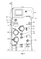
- Figs. 1 and 2 illustrate an exemplary fluid processing system 10
- FIG. 3 illustrates an exemplary fluid flow circuit 12 mounted onto the fluid processing system 10, but it should be understood that the illustrated fluid processing system 10 and fluid flow circuit 12 are merely exemplary of such systems and circuits and that differently configured fluid processing systems and fluid flow circuits may be provided without departing from the scope of the present disclosure.
- the system 10 of Fig. 1 is configured for separating whole blood, but it may be used with any fluid to be processed and then at least partially returned to a fluid source or other recipient.
- the fluid may come from any fluid source and be returned to any recipient, which may be the same as or different from the fluid source.
- the fluid source/recipient is a living donor or patient (e.g., a human blood donor), while in other embodiments the fluid source and/or fluid recipient may be a non-living source/recipient (e.g., a blood bag or fluid container).
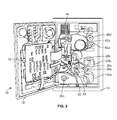
- the illustrated system 10 includes a cabinet or housing 14, with several components positioned outside of the cabinet 14 (e.g., associated with a front wall or surface or panel of the cabinet 14) and additional components (including a central processing unit or controller 16) and interconnects positioned inside of the cabinet 14, which may be accessed by opening a rear door 18 of the system 10, as shown in Fig. 2 .
- additional components including a central processing unit or controller 16
- interconnects positioned inside of the cabinet 14, which may be accessed by opening a rear door 18 of the system 10, as shown in Fig. 2 .
- a central processing unit or controller 16 a central processing unit or controller
- One of the pumps 20a may be provided as a source/recipient access pump or fluid recipient pump, which may be associated with a source/recipient access line or fluid recipient line 22 of the fluid flow circuit 12 and operates to draw fluid from a fluid source ( Fig. 5 ) and to return fluid to a fluid recipient ( Fig. 6 ).
- Another one of the pumps 20b may be provided as an anticoagulant pump, which may be associated with an anticoagulant line 24 of the fluid flow circuit 12 and operates to add anticoagulant from an anticoagulant source or container 26 of the fluid flow circuit 12 ( Fig. 5 ) to fluid drawn from the fluid source in the source/recipient access line 22 before the fluid enters into a fluid processing or separation module or chamber 28 of the fluid flow circuit 12.
- a third pump 20c may be provided as a return fluid pump or processed fluid pump, which may be associated with a return fluid outlet line 30 and operates to draw a return fluid (i.e., a fluid constituent to be returned to a fluid recipient) from the fluid separation chamber 28 and direct it into a return fluid reservoir or processed fluid reservoir 32 after the fluid has been separated into a return fluid and a collection fluid in the fluid separation chamber 28.
- a return fluid i.e., a fluid constituent to be returned to a fluid recipient
- the pumps 20a-20c are rotatable peristaltic pumps, but it is within the scope of the present disclosure for differently configured pumps, such as diaphragm or other pumps, to be provided. Furthermore, additional or alternative pumps may be provided without departing from the scope of the present disclosure.
- a pump may be associated with a collection fluid outlet line 34 of the fluid flow circuit 12 to draw a collection fluid from the fluid separation chamber 28 after the fluid from the fluid source has been separated into a return fluid and a collection fluid.
- the illustrated embodiment employs a single fluid flow tubing or flow path for both drawing fluid from a source and flowing or returning it to a recipient, which are carried out intermittently.
- the system 10 could employ separate draw and return flow paths or tubes without departing from the scope of the present disclosure.
- the external components of the system 10 may include one or more clamps or valves 36a-36d associated with the tubing lines of the fluid flow circuit 12.
- the clamps or valves 36a-36d may be variously configured and operate to selectively allow and prevent fluid flow through the associated tubing line.
- one clamp or valve 36a may be provided as a fluid source/recipient clamp, which may be associated with a draw branch 22a of the source/recipient access line 22 of the fluid flow circuit 12 to allow ( Fig. 5 ) or prevent ( Fig. 6 ) the flow of fluid through the draw branch 22a of the source/recipient access line 22.
- clamps or valves 36b may be provided as a reinfusion clamp or valve, which may be associated with a reinfusion branch 22b of the source/recipient access line 22 downstream of the return fluid reservoir 32 of the fluid flow circuit 12 to allow ( Fig. 6 ) or prevent ( Fig. 5 ) the flow of return fluid through the reinfusion branch 22b.
- a third clamp or valve 36c may be provided as a collection fluid clamp or valve, which may be associated with the collection fluid outlet line 34 to allow ( Fig. 5 ) or prevent ( Fig. 6 ) the flow of collection fluid through the collected outlet line 34 and into a collection fluid container 38.
- a fourth clamp or valve 36d may be provided as a replacement fluid clamp or valve, which may be associated with a replacement fluid line 40 of the fluid flow circuit 12 to allow or prevent the flow of a replacement fluid out of a replacement fluid source 42 (e.g., a bag or container at least partially filled with saline). Additional or alternative clamps or valves may also be provided without departing from the scope of the present disclosure.
- a replacement fluid source 42 e.g., a bag or container at least partially filled with saline. Additional or alternative clamps or valves may also be provided without departing from the scope of the present disclosure.
- the illustrated system 10 further includes one or more pressure sensors 43a and 43b that may be associated with the fluid flow circuit 12 to monitor the pressure within one or more of the tubing lines of the fluid flow circuit 12 during operation of the pumps 20a-20c and clamps or valves 36a-36d.
- one pressure sensor 43a may be associated with a tubing line that draws fluid from a fluid source and/or directs processed fluid to a fluid recipient
- the other pressure sensor 43b may be associated with a tubing line that directs fluid into or out of the fluid separation chamber 28 to assess the pressure within the fluid separation chamber 28, but the pressure sensors 43a and 43b may also be associated with other tubing lines without departing from the scope of the present disclosure.
- the pressure sensors 43a and 43b may send signals to the system controller 16 that are indicative of the pressure within the tubing line or lines being monitored by the pressure sensor 43a, 43b. If the controller 16 determines that an improper pressure is present within the fluid flow circuit 12 (e.g., a high pressure due to an occlusion of one of the tubing lines), then the controller 16 may instruct one or more of the pumps 20a-20c and/or one or more of the clamps or valves 36a-36d to act so as to alleviate the improper pressure condition (e.g., by reversing the direction of operation of one of the pumps 20a-20c and/or opening or closing one of the clamps or valves 36a-36d). Additional or alternative pressure sensors may also be provided without departing from the scope of the present disclosure.
- the system 10 may also include a separation actuator or processing actuator 44 that interacts with a portion of the fluid separation chamber 28 to operate the fluid separation chamber 28.
- a chamber lock 46 may also be provided to hold the fluid separation chamber 28 in place with respect to the system cabinet 14 and in engagement with the separation actuator 44.
- the configuration and operation of the separation actuator 44 depends upon the configuration of the fluid separation chamber 28.
- the fluid separation chamber 28 is provided as a spinning membrane-type separator, such as a separator of the type described in greater detail in U.S. Patents Nos. 5,194,145 and 5,234,608 or in PCT Patent Application Publication No. WO 2012/125457 A1 , all of which are hereby incorporated herein by reference.
- the fluid separation chamber 28 may include a tubular housing 48 ( Fig. 4 ), with a microporous membrane 50 positioned therein.
- An inlet 52 allows a fluid from a fluid source to enter into the housing 48 (via the draw branch 22a of the source/recipient access line 22), while a side outlet 54 allows return fluid to exit the housing 48 (via the return fluid outlet line 30) and a bottom outlet 56 allows collection fluid to exit the housing 48 (via the collection fluid outlet line 34) after the fluid from the fluid source has been separated into return fluid and collection fluid.
- the separation actuator 44 is provided as a driver that is magnetically coupled to a rotor 58 on which the membrane 50 is mounted, with the separation actuator 44 causing the rotor 58 and membrane 50 to rotate about the central axis of the housing 48.
- the rotating rotor 58 and membrane 50 create Taylor vortices within a gap 60 between the housing 48 and the membrane 50, which tend to transport the return fluid away from the membrane 50 to exit the fluid separation chamber 28 via the side outlet 54, while the collection fluid passes through the membrane 50 toward the central axis of the housing 48 to exit the fluid separation chamber 28 via the bottom outlet 56.
- whole blood from a blood source is separated into cellular blood components (return fluid) and substantially cell-free plasma (collection fluid).
- the present disclosure is not limited to a particular fluid processing chamber or device and that the illustrated and described chamber 28, which separates the fluid into two constituents, is merely exemplary.
- a centrifugal device that separates fluid components based on density, rather than size, may be employed instead of a spinning membrane-type fluid separation chamber, or a processing device that treats the fluid without separating it (e.g., a photo-inactivation chamber) may be incorporated into the fluid flow circuit 12 without departing from the scope of the present disclosure.
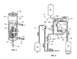
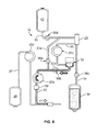
- a fluid is drawn from a fluid source into the fluid separation chamber 28 during a draw phase or mode ( Fig. 5 ), where it separated into return fluid and collection fluid.
- the collection fluid is retained by the system 10, while the return fluid is returned to the fluid source during a return or reinfusion phase or mode ( Fig. 6 ).
- the draw and return phases are repeatedly alternated (drawing from the fluid source, separating the fluid from the fluid source into return fluid and collection fluid, and then pumping the collection fluid to the fluid source or a different recipient) until a target (e.g., a particular amount of collection fluid) is achieved.
- All of the draw phases and all of the return phases may be identical or may differ from each other. For example, a final draw phase may draw less fluid from the fluid source than the previous draw phases and a final return phase may infuse a combination of return fluid and replacement fluid to the fluid recipient, whereas the previous return phases pump only return fluid to the fluid recipient.
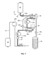
- Fig. 7 shows an exemplary phase or mode in which replacement fluid (e.g., saline) is directed to the fluid recipient, either alone or with an amount of return/processed fluid.
- replacement fluid e.g., saline
- the clamp or valve 36d associated with the replacement fluid line 40 is opened to allow replacement fluid to flow out of the replacement fluid source 42.
- the clamp or valve 36a associated with the draw branch 22a of the source/recipient access line 22 may be in a closed condition to prevent fluid flow therethrough, such that the replacement fluid is directed into the fluid separation chamber 28.
- the replacement fluid is pulled out of the fluid separation chamber 28 and into the return fluid reservoir 32 by operation of the pump 20c associated with the return fluid outlet line 30.
- the replacement fluid mixes with the return fluid prior to being pumped to the fluid recipient by the pump 20a associated with the fluid recipient line 22, otherwise the replacement fluid alone may be pumped to the fluid recipient.
- the replacement fluid return mode of Fig. 7 is carried out only once, as a final return phase (e.g., when the amount of return fluid in the return fluid reservoir 32 is at a sufficiently low level) in which a mixture of return fluid and replacement fluid is returned to the fluid recipient. This may be advantageous to ensure that all of the return fluid in the return fluid reservoir 32 (along with any remaining in the fluid separation chamber 28) is rinsed out of the return fluid reservoir 32 and pumped to the fluid recipient.
- the replacement fluid return mode of Fig. 7 may be carried out at other times, such as earlier in the procedure, at multiple scheduled times during a procedure, and/or at any time upon a request from the operator and/or using a different path between the replacement fluid source 42 and the fluid recipient.
- the replacement fluid may bypass the fluid separation chamber 28 and the return fluid reservoir 32 if the replacement fluid is being pumped to a fluid recipient earlier in the procedure.
- the clamp or valve 36d associated with the replacement fluid line 40 and the clamp or valve 36a associated with the draw branch 22a of the source/recipient access line 22 may be opened to allow fluid flow therethrough, with the clamp or valve 36b associated with the reinfusion branch 22b in a closed condition to prevent fluid flow therethrough.
- the pump 20a associated with the fluid recipient line 22 may be activated (with the other two pumps 20b and 20c inactive) to draw replacement fluid out of the replacement fluid source 42 and through the replacement fluid line 40, the draw branch 22a, and finally the source/recipient access line 22 to the fluid recipient.
- the processed or return fluid and/or replacement fluid being returned to the fluid recipient may be monitored to detect the presence of air.
- Detection of air in a fluid return line of a fluid processing system e.g., an apheresis system or a dialysis system
- any suitable air detection assembly may be incorporated into fluid processing systems according to the present disclosure.
- an air detection assembly 62 of the fluid processing system 10 is part of the front panel of the cabinet 14, and configured to receive a portion of the reinfusion branch 22b of the fluid recipient line 22.
- the illustrated air detection assembly 62 is positioned downstream of the fluid recipient pump 20a (i.e., between the fluid recipient pump 20a and the fluid recipient), with the fluid recipient pump 20a being positioned between the processed fluid reservoir 32 and the air detection assembly 62 when the fluid flow circuit 12 has been mounted onto the fluid processing system 10.
- the air detection assembly 62 may be provided as an ultrasonic monitoring device, with at least one sound wave emitter and at least one sound wave receiver positioned on opposite sides of the fluid recipient line 22.
- An ultrasonic sound wave will travel through fluid (e.g., return fluid and/or replacement fluid) substantially unimpeded, whereas an ultrasonic sound wave traveling through an air bubble will arrive at the receiver with a reduced magnitude.
- the air detection assembly 62 may be associated with the system controller 16, which may issue instructions to the air detection assembly 62 (e.g., instructing the sound wave emitter and receiver when to be operative) and receive signals or outputs generated by the air detection assembly 62 (e.g., receiving an output of the sound wave receiver that is indicative of the contents of the reinfusion branch 22b of the fluid recipient line 22 passing through the air detection assembly 62). If the controller 16 receives an output from the sound wave receiver that is indicative of a low magnitude sound wave, then the controller may interpret the output as signifying the presence of air in the fluid recipient line 22. In other embodiments, other air detection assembly configurations (e.g., an optical monitor) and/or methods for detecting air in the fluid recipient line 22 may be employed without departing from the scope of the present disclosure.
- other air detection assembly configurations e.g., an optical monitor
- methods for detecting air in the fluid recipient line 22 may be employed without departing from the scope of the present disclosure.
- the controller 16 may automatically take steps to remove the air from the fluid recipient line 22. For example, in one embodiment, the controller 16 is programmed to pause or stop the operation of the fluid recipient pump 20a when air is detected in the fluid recipient line 22 moving toward the fluid recipient. If any of the other pumps 20b, 20c are operating, then the controller 16 may either pause operation of them as well or allow them to continue operating, either as before or in a modified capacity. The controller 16 may also generate an alert or an alarm to notify an operator that air is in the fluid recipient line 22 and that the system 10 is taking automated steps to remove the air from the fluid recipient line 22.
- the controller 16 may then automatically instruct the fluid recipient pump 20a to operate in a second or reverse direction to move processed fluid and/or replacement fluid in the fluid recipient line 22 in a direction away from the fluid recipient to prevent air from being infused into the fluid recipient, which may be harmful if the fluid recipient is a living recipient (e.g., a human).
- the air detection assembly 62 may continue monitoring the processed fluid and/or replacement fluid in the fluid recipient line 22 as the fluid recipient pump 20a operates in the reverse direction to allow the controller 16 to confirm or verify that the air in the fluid recipient line 22 has been passed through the air detection assembly 62 away from the fluid recipient.
- the fluid recipient pump 20a continues operating in the reverse or second direction until the air in the fluid recipient line 22 has been removed from the fluid recipient line 22.
- the location at which the air is removed from the fluid recipient line 22 may vary without departing from the scope of the present disclosure.
- the processed fluid and/or replacement fluid in the fluid recipient line 22 may be pumped into the processed fluid reservoir 32 at least until the air in the fluid recipient line 22 enters the processed fluid reservoir 32.
- the processed fluid reservoir 32 may be a flexible, expandable bag or container, such that air in the processed fluid reservoir 32 separates from the processed fluid and/or replacement fluid and partially inflates the processed fluid reservoir 32, effectively removing the air from the fluid recipient line 22.
- the controller 16 may determine when air has been removed from the fluid recipient line 22 in any suitable manner. For example, in one embodiment, the controller 16 may determine the amount of processed fluid and/or replacement fluid in the fluid recipient line 22 between the air and the processed fluid reservoir 32, which depends on the length of the fluid recipient line 22 between the air detection assembly 62 and the processed fluid reservoir 32. This may be advantageous if the length of the fluid recipient line 22 between the air detection assembly 62 and the processed fluid reservoir 32 is known, such as if a portion of the fluid recipient line 22 is particularly configured to be received within the air detection assembly 62 (e.g., by including a fixture that is pressed into the air detection assembly 62).
- the controller 16 may instruct the fluid recipient pump 20a to pump an additional amount of processed fluid and/or replacement fluid into the processed fluid reservoir 32 to ensure that the air has been removed from the fluid recipient line 22.
- the length of the fluid recipient line 22 between the processed fluid reservoir 32 and the air detection assembly 62 may vary, which may be the case if any portion of the fluid recipient line 22 may be received by the air detection assembly 62, rather than having a designated portion of the fluid recipient line 22 positioned within the air detection assembly 62.
- the controller 16 may be programmed to operate the fluid recipient pump 20a a predetermined or preselected amount of time or to a predetermined or preselected extent to ensure that the air has been removed from the fluid recipient line 22.
- the controller 16 may be programmed to instruct the fluid recipient pump 20a to operate in the reverse or second direction a preselected or predetermined number of rotations to ensure that the air in the fluid recipient line 22 has been pumped into the processed fluid reservoir 32.
- the system 10 includes a processed fluid weigh scale 64 ( Figs. 1 and 2 ) associated with the processed fluid reservoir 32.
- the processed fluid weigh scale 64 may weigh the processed fluid reservoir 32 and the processed fluid and/or replacement fluid contained therein.
- the controller 16 monitors the output of the processed fluid weigh scale 64 to determine that a sufficient amount of processed fluid and/or replacement fluid has been pumped back into the processed fluid reservoir 32 by the fluid recipient pump 20a so as to clear the air from the fluid recipient line 22.
- the controller 16 may instruct the fluid recipient pump 20a to operate in the first or forward direction to move fluid through the fluid recipient line 22 toward and to the fluid recipient.
- the controller 16 may continuously or periodically monitor and record the weight registered by the processed fluid weigh scale 64, such that the controller 16 is aware of the weight of the processed fluid reservoir 32 and the processed fluid and/or replacement fluid therein at different times throughout the course of a procedure.
- the controller 16 may pause operation of the fluid recipient pump 20a.
- the controller 16 may compare the weight registered by the processed fluid weigh scale 64 at this time (which may be referred to as the "post-detection weight") to the weight registered by the processed fluid weigh scale 64 at a time before the air detection assembly 62 detected air in the fluid recipient line 22 (which may be referred to as the "pre-detection weight"). If the post-detection weight is sufficiently greater than the pre-detection weight, then the controller 16 will have verified that enough processed fluid and/or replacement fluid has been pumped back into the processed fluid reservoir 32 to remove the air from the fluid recipient line 22.
- the difference in the pre- and post-detection weight that is required for the controller 16 to verify purgation of the air may vary without departing from the scope of the present disclosure.
- the amount of fluid pumped through the fluid recipient line 22 by the fluid recipient pump 20a during this response time may be referred to as the "post-detection amount" of fluid.
- the weight difference that is required for the controller 16 to verify purgation of air is at least equal to the sum of the weight of the fluid between the processed fluid reservoir 32 and the air detection assembly 62 plus the weight of the "post-detection amount" of fluid, which sum is equal to the weight of the fluid between the processed fluid reservoir 32 and the air bubble. It may be preferred to return an additional amount of fluid to the processed fluid reservoir 32 to ensure that the air has been pumped into the processed fluid reservoir 32.
- the controller 16 may determine the amount of time required for processed fluid and/or replacement fluid to be pumped from the processed fluid reservoir 32 to the air detection assembly 62, which may correspond to the amount of time required for the air to have been pumped from the processed fluid reservoir 32 to the air detection assembly 62. This amount of time is dependent on the length of the fluid recipient line 22 between the processed fluid reservoir 32 and the air detection assembly 62 and the volumetric flow rate of the processed fluid and/or replacement fluid through the fluid recipient line 22, which the controller 16 may determine by monitoring the operation of the fluid recipient pump 20a.
- the controller 16 may count backwards from the time that the air was detected by the air detection assembly 62 to determine the time that the air may have entered the fluid recipient line 22 from the processed fluid reservoir 32.
- the weight registered by the processed fluid weigh scale 64 shortly before this time (e.g., one second earlier) may be used to select the pre-detection weight as a safety measure, to ensure that enough processed fluid and/or replacement fluid has been pumped to the processed fluid reservoir 32 to remove the air from the fluid recipient line 22.
- the time selected for the pre-detection weight may be a standard amount of time (e.g., five seconds) before air was detected by the air detection assembly 62.
- an additional amount of fluid may be returned to the processed fluid reservoir 32 to account for the aforementioned response time for the pump 20a to be paused and/or to provide a safety buffer that ensures that more than enough fluid has been pumped into the processed fluid reservoir 32 to purge the air bubble.
- the controller 16 may instruct the fluid recipient pump 20a to operate in the first or forward direction to move fluid through the fluid recipient line 22 toward and to the fluid recipient.
- the controller 16 may also generate an alarm or alert to notify the operator that the air has been cleared from the fluid recipient line 22 and that the fluid return phase is being continued.
Abstract
Description
- The invention relates to fluid processing systems and methods. More particularly, the invention relates to systems and methods for detecting air in a fluid return line and automatically purging the air therefrom.
- Various blood processing systems now make it possible to collect particular blood constituents, instead of whole blood, from a blood source such as, but not limited to, a container of previously collected blood or other living or non-living source. Typically, in such systems, whole blood is drawn from a blood source, a particular blood component or constituent is separated, removed, and collected, and the remaining blood constituents are returned to the blood source. Removing only particular constituents is advantageous when the blood source is a human donor, because potentially less time is needed for the donor's body to return to pre-donation levels, and donations can be made at more frequent intervals than when whole blood is collected. This increases the overall supply of blood constituents, such as plasma and platelets, made available for transfer and/or therapeutic treatment.
- Whole blood is typically separated into its constituents (e.g., red cells, platelets, and plasma) through centrifugation, such as in the AMICUS® separator from Fenwal, Inc. of Lake Zurich, Illinois, or other centrifugal separation devices, or a spinning membrane-type separator, such as the AUTOPHERESIS-C® and AURORA® devices from Fenwal, Inc.
- In some of these systems, an air detector is provided for detecting the presence of air bubbles in fluid being returned to the blood source. Known systems typically include an alert and/or alarm system that is programmed to generate an alert and/or alarm when air is detected in a fluid return line, which causes the pumps of the system to stop operating and closes the clamps or valves of the system to prevent air from being injected into the blood source. The intervention of an operator is then required to remove the air from the fluid return line, such as by pressing a button to cause the air to be vented from the fluid return line and then pressing another button to restart the system after visually confirming that the air has been vented. However, human interaction may prolong the time that the system is paused or inoperative, especially if a single operator is overseeing the simultaneous operation of multiple systems. Accordingly, the need remains for a fluid processing system that can automatically purge air from a fluid return line without requiring human intervention.
- There are several aspects of the present subject matter which may be embodied separately or together in the devices and systems described and claimed below. These aspects may be employed alone or in combination with other aspects of the subject matter described herein, and the description of these aspects together is not intended to preclude the use of these aspects separately or the claiming of such aspects separately or in different combinations as set forth in the claims appended hereto.
- In one aspect, a fluid processing system is provided for processing fluid and returning processed fluid and/or replacement fluid to a fluid recipient. The fluid processing system is configured to cooperate with a fluid flow circuit, which includes a fluid recipient line for returning processed fluid and/or replacement fluid from a fluid processing chamber to a fluid recipient. The system includes a fluid recipient pump operable in a first direction to pump processed fluid and/or replacement fluid through the fluid recipient line toward the fluid recipient and in a second direction to pump processed fluid and/or replacement fluid through the fluid recipient line away from the fluid recipient. The system also includes an air detection assembly configured to monitor the contents of the fluid recipient line and produce an output indicative of the presence of air in the fluid recipient line flowing toward the fluid recipient. A controller of the system is programmed to automatically instruct the fluid recipient pump to operate in the second direction (upon receiving the output from the air detection assembly) to pump processed fluid and/or replacement fluid containing air through the fluid recipient line away from the fluid recipient at least until the air in the fluid recipient line is removed from the fluid recipient line.
- In another aspect, the combination of a fluid processing system and a fluid flow circuit configured to cooperate with the fluid processing system are provided for processing fluid and returning processed fluid and/or replacement fluid to a fluid recipient. The fluid flow circuit includes a fluid processing chamber and a fluid recipient line for returning processed fluid and/or replacement fluid from the fluid processing chamber to a fluid recipient. The fluid processing system includes a fluid recipient pump operable in a first direction to pump processed fluid and/or replacement fluid through the fluid recipient line toward the fluid recipient and in a second direction to pump processed fluid and/or replacement fluid through the fluid recipient line away from the fluid recipient. The system also includes an air detection assembly configured to monitor the contents of the fluid recipient line and produce an output indicative of the presence of air in the fluid recipient line flowing toward the fluid recipient. A controller of the system is programmed to automatically instruct the fluid recipient pump to operate in the second direction (upon receiving the output from the air detection assembly) to pump processed fluid and/or replacement fluid containing air through the fluid recipient line away from the fluid recipient at least until the air in the fluid recipient line is removed from the fluid recipient line.
- In yet another aspect, a method of controlling a fluid processing system is provided to process a fluid and pump processed fluid and/or replacement fluid through the fluid processing system. The method includes processing fluid within a fluid processing system. Processed fluid and/or replacement fluid is pumped through the fluid processing system in a first direction , with the fluid being monitored to detect the presence of air. If air is detected in the processed fluid and/or replacement fluid being pumped through the fluid processing system in the first direction, then the processed fluid and/or replacement fluid containing air is automatically pumped in a direction opposite to the first direction until the air has been removed from the processed fluid and/or replacement fluid.
-
-
Fig. 1 is a front perspective view of an exemplary fluid processing system according to an aspect of the present disclosure; -
Fig. 2 is a rear perspective view of the fluid processing system ofFig. 1 , with a rear door thereof in an open position; -
Fig. 3 is a front perspective view of the fluid processing system ofFig. 1 , with a fluid flow circuit associated therewith; -
Fig. 4 is a front perspective view of a fluid separation chamber of the fluid flow circuit ofFig. 3 , with a portion thereof broken away for illustrative purposes; -
Fig. 5 is a schematic view of the fluid flow circuit and fluid processing system ofFig. 3 , in a fluid draw mode; -
Fig. 6 is a schematic view of the fluid flow circuit and fluid processing system ofFig. 3 , in a fluid return mode; and -
Fig. 7 is a schematic view of the fluid flow circuit and fluid processing system ofFig. 3 , in a replacement fluid return mode. - The embodiments disclosed herein are for the purpose of providing an exemplary description of the present subject matter. They are, however, only exemplary, and the present subject matter may be embodied in various forms. Therefore, specific details disclosed herein are not to be interpreted as limiting the subject matter as defined in the accompanying claims.
- According to an aspect of the present disclosure, a durable or reusable fluid processing system is used in combination with a separate fluid flow circuit (which may be disposable) to process a fluid from a fluid source, such as by separating the fluid into two or more constituent parts (as will be described in greater detail herein) or infusing an additive into the fluid or otherwise treating the fluid (e.g., by employing a photo-inactivation step).
Figs. 1 and2 illustrate an exemplaryfluid processing system 10, whileFig. 3 illustrates an exemplaryfluid flow circuit 12 mounted onto thefluid processing system 10, but it should be understood that the illustratedfluid processing system 10 andfluid flow circuit 12 are merely exemplary of such systems and circuits and that differently configured fluid processing systems and fluid flow circuits may be provided without departing from the scope of the present disclosure. - The
system 10 ofFig. 1 is configured for separating whole blood, but it may be used with any fluid to be processed and then at least partially returned to a fluid source or other recipient. The fluid may come from any fluid source and be returned to any recipient, which may be the same as or different from the fluid source. In one embodiment, the fluid source/recipient is a living donor or patient (e.g., a human blood donor), while in other embodiments the fluid source and/or fluid recipient may be a non-living source/recipient (e.g., a blood bag or fluid container). - The illustrated
system 10 includes a cabinet orhousing 14, with several components positioned outside of the cabinet 14 (e.g., associated with a front wall or surface or panel of the cabinet 14) and additional components (including a central processing unit or controller 16) and interconnects positioned inside of thecabinet 14, which may be accessed by opening arear door 18 of thesystem 10, as shown inFig. 2 . Among the system components positioned on the outside of thecabinet 14, one or more pumps orpump stations 20a-20c may be provided, with thepumps 20a-20c configured to accommodate tubing lines of thefluid flow circuit 12. One of thepumps 20a may be provided as a source/recipient access pump or fluid recipient pump, which may be associated with a source/recipient access line orfluid recipient line 22 of thefluid flow circuit 12 and operates to draw fluid from a fluid source (Fig. 5 ) and to return fluid to a fluid recipient (Fig. 6 ). Another one of thepumps 20b may be provided as an anticoagulant pump, which may be associated with ananticoagulant line 24 of thefluid flow circuit 12 and operates to add anticoagulant from an anticoagulant source orcontainer 26 of the fluid flow circuit 12 (Fig. 5 ) to fluid drawn from the fluid source in the source/recipient access line 22 before the fluid enters into a fluid processing or separation module orchamber 28 of thefluid flow circuit 12. Athird pump 20c may be provided as a return fluid pump or processed fluid pump, which may be associated with a returnfluid outlet line 30 and operates to draw a return fluid (i.e., a fluid constituent to be returned to a fluid recipient) from thefluid separation chamber 28 and direct it into a return fluid reservoir or processedfluid reservoir 32 after the fluid has been separated into a return fluid and a collection fluid in thefluid separation chamber 28. - In the illustrated embodiment, the
pumps 20a-20c are rotatable peristaltic pumps, but it is within the scope of the present disclosure for differently configured pumps, such as diaphragm or other pumps, to be provided. Furthermore, additional or alternative pumps may be provided without departing from the scope of the present disclosure. For example, a pump may be associated with a collectionfluid outlet line 34 of thefluid flow circuit 12 to draw a collection fluid from thefluid separation chamber 28 after the fluid from the fluid source has been separated into a return fluid and a collection fluid. Also, as will be described in greater detail herein, the illustrated embodiment employs a single fluid flow tubing or flow path for both drawing fluid from a source and flowing or returning it to a recipient, which are carried out intermittently. Thesystem 10 could employ separate draw and return flow paths or tubes without departing from the scope of the present disclosure. - In addition to the
pumps 20a-20c, the external components of thesystem 10 may include one or more clamps orvalves 36a-36d associated with the tubing lines of thefluid flow circuit 12. The clamps orvalves 36a-36d may be variously configured and operate to selectively allow and prevent fluid flow through the associated tubing line. In the illustrated embodiment, one clamp orvalve 36a may be provided as a fluid source/recipient clamp, which may be associated with adraw branch 22a of the source/recipient access line 22 of thefluid flow circuit 12 to allow (Fig. 5 ) or prevent (Fig. 6 ) the flow of fluid through thedraw branch 22a of the source/recipient access line 22. Another one of the clamps orvalves 36b may be provided as a reinfusion clamp or valve, which may be associated with areinfusion branch 22b of the source/recipient access line 22 downstream of thereturn fluid reservoir 32 of thefluid flow circuit 12 to allow (Fig. 6 ) or prevent (Fig. 5 ) the flow of return fluid through thereinfusion branch 22b. A third clamp orvalve 36c may be provided as a collection fluid clamp or valve, which may be associated with the collectionfluid outlet line 34 to allow (Fig. 5 ) or prevent (Fig. 6 ) the flow of collection fluid through the collectedoutlet line 34 and into acollection fluid container 38. A fourth clamp orvalve 36d may be provided as a replacement fluid clamp or valve, which may be associated with areplacement fluid line 40 of thefluid flow circuit 12 to allow or prevent the flow of a replacement fluid out of a replacement fluid source 42 (e.g., a bag or container at least partially filled with saline). Additional or alternative clamps or valves may also be provided without departing from the scope of the present disclosure. - The illustrated
system 10 further includes one ormore pressure sensors fluid flow circuit 12 to monitor the pressure within one or more of the tubing lines of thefluid flow circuit 12 during operation of thepumps 20a-20c and clamps orvalves 36a-36d. In one embodiment, onepressure sensor 43a may be associated with a tubing line that draws fluid from a fluid source and/or directs processed fluid to a fluid recipient, while theother pressure sensor 43b may be associated with a tubing line that directs fluid into or out of thefluid separation chamber 28 to assess the pressure within thefluid separation chamber 28, but thepressure sensors pressure sensors system controller 16 that are indicative of the pressure within the tubing line or lines being monitored by thepressure sensor controller 16 determines that an improper pressure is present within the fluid flow circuit 12 (e.g., a high pressure due to an occlusion of one of the tubing lines), then thecontroller 16 may instruct one or more of thepumps 20a-20c and/or one or more of the clamps orvalves 36a-36d to act so as to alleviate the improper pressure condition (e.g., by reversing the direction of operation of one of thepumps 20a-20c and/or opening or closing one of the clamps orvalves 36a-36d). Additional or alternative pressure sensors may also be provided without departing from the scope of the present disclosure. - The
system 10 may also include a separation actuator orprocessing actuator 44 that interacts with a portion of thefluid separation chamber 28 to operate thefluid separation chamber 28. Achamber lock 46 may also be provided to hold thefluid separation chamber 28 in place with respect to thesystem cabinet 14 and in engagement with theseparation actuator 44. The configuration and operation of theseparation actuator 44 depends upon the configuration of thefluid separation chamber 28. In the illustrated embodiment, thefluid separation chamber 28 is provided as a spinning membrane-type separator, such as a separator of the type described in greater detail inU.S. Patents Nos. 5,194,145 and5,234,608 or inPCT Patent Application Publication No. WO 2012/125457 A1 fluid separation chamber 28 may include a tubular housing 48 (Fig. 4 ), with amicroporous membrane 50 positioned therein. Aninlet 52 allows a fluid from a fluid source to enter into the housing 48 (via thedraw branch 22a of the source/recipient access line 22), while aside outlet 54 allows return fluid to exit the housing 48 (via the return fluid outlet line 30) and abottom outlet 56 allows collection fluid to exit the housing 48 (via the collection fluid outlet line 34) after the fluid from the fluid source has been separated into return fluid and collection fluid. - In the illustrated embodiment, the
separation actuator 44 is provided as a driver that is magnetically coupled to arotor 58 on which themembrane 50 is mounted, with theseparation actuator 44 causing therotor 58 andmembrane 50 to rotate about the central axis of thehousing 48. The rotatingrotor 58 andmembrane 50 create Taylor vortices within agap 60 between thehousing 48 and themembrane 50, which tend to transport the return fluid away from themembrane 50 to exit thefluid separation chamber 28 via theside outlet 54, while the collection fluid passes through themembrane 50 toward the central axis of thehousing 48 to exit thefluid separation chamber 28 via thebottom outlet 56. In one embodiment, whole blood from a blood source is separated into cellular blood components (return fluid) and substantially cell-free plasma (collection fluid). It should be understood that the present disclosure is not limited to a particular fluid processing chamber or device and that the illustrated and describedchamber 28, which separates the fluid into two constituents, is merely exemplary. For example, in other embodiments, a centrifugal device that separates fluid components based on density, rather than size, may be employed instead of a spinning membrane-type fluid separation chamber, or a processing device that treats the fluid without separating it (e.g., a photo-inactivation chamber) may be incorporated into thefluid flow circuit 12 without departing from the scope of the present disclosure. - According to one method of using the illustrated
fluid processing system 10 andfluid flow circuit 12, a fluid is drawn from a fluid source into thefluid separation chamber 28 during a draw phase or mode (Fig. 5 ), where it separated into return fluid and collection fluid. The collection fluid is retained by thesystem 10, while the return fluid is returned to the fluid source during a return or reinfusion phase or mode (Fig. 6 ). In one embodiment, the draw and return phases are repeatedly alternated (drawing from the fluid source, separating the fluid from the fluid source into return fluid and collection fluid, and then pumping the collection fluid to the fluid source or a different recipient) until a target (e.g., a particular amount of collection fluid) is achieved. All of the draw phases and all of the return phases may be identical or may differ from each other. For example, a final draw phase may draw less fluid from the fluid source than the previous draw phases and a final return phase may infuse a combination of return fluid and replacement fluid to the fluid recipient, whereas the previous return phases pump only return fluid to the fluid recipient. -
Fig. 7 shows an exemplary phase or mode in which replacement fluid (e.g., saline) is directed to the fluid recipient, either alone or with an amount of return/processed fluid. In the phase ofFig. 7 , the clamp orvalve 36d associated with thereplacement fluid line 40 is opened to allow replacement fluid to flow out of thereplacement fluid source 42. The clamp orvalve 36a associated with thedraw branch 22a of the source/recipient access line 22 may be in a closed condition to prevent fluid flow therethrough, such that the replacement fluid is directed into thefluid separation chamber 28. The replacement fluid is pulled out of thefluid separation chamber 28 and into thereturn fluid reservoir 32 by operation of thepump 20c associated with the returnfluid outlet line 30. If there is any return fluid in thereturn fluid reservoir 32, then the replacement fluid mixes with the return fluid prior to being pumped to the fluid recipient by thepump 20a associated with thefluid recipient line 22, otherwise the replacement fluid alone may be pumped to the fluid recipient. In one embodiment, the replacement fluid return mode ofFig. 7 is carried out only once, as a final return phase (e.g., when the amount of return fluid in thereturn fluid reservoir 32 is at a sufficiently low level) in which a mixture of return fluid and replacement fluid is returned to the fluid recipient. This may be advantageous to ensure that all of the return fluid in the return fluid reservoir 32 (along with any remaining in the fluid separation chamber 28) is rinsed out of thereturn fluid reservoir 32 and pumped to the fluid recipient. - In other embodiments, the replacement fluid return mode of
Fig. 7 may be carried out at other times, such as earlier in the procedure, at multiple scheduled times during a procedure, and/or at any time upon a request from the operator and/or using a different path between thereplacement fluid source 42 and the fluid recipient. For example, it may be advantageous for the replacement fluid to bypass thefluid separation chamber 28 and thereturn fluid reservoir 32 if the replacement fluid is being pumped to a fluid recipient earlier in the procedure. In this case, the clamp orvalve 36d associated with thereplacement fluid line 40 and the clamp orvalve 36a associated with thedraw branch 22a of the source/recipient access line 22 may be opened to allow fluid flow therethrough, with the clamp orvalve 36b associated with thereinfusion branch 22b in a closed condition to prevent fluid flow therethrough. Thepump 20a associated with thefluid recipient line 22 may be activated (with the other twopumps replacement fluid source 42 and through thereplacement fluid line 40, thedraw branch 22a, and finally the source/recipient access line 22 to the fluid recipient. - The processed or return fluid and/or replacement fluid being returned to the fluid recipient may be monitored to detect the presence of air. Detection of air in a fluid return line of a fluid processing system (e.g., an apheresis system or a dialysis system) is known, and any suitable air detection assembly may be incorporated into fluid processing systems according to the present disclosure. In the illustrated embodiment, an
air detection assembly 62 of thefluid processing system 10 is part of the front panel of thecabinet 14, and configured to receive a portion of thereinfusion branch 22b of thefluid recipient line 22. The illustratedair detection assembly 62 is positioned downstream of thefluid recipient pump 20a (i.e., between thefluid recipient pump 20a and the fluid recipient), with thefluid recipient pump 20a being positioned between the processedfluid reservoir 32 and theair detection assembly 62 when thefluid flow circuit 12 has been mounted onto thefluid processing system 10. - In one embodiment, the
air detection assembly 62 may be provided as an ultrasonic monitoring device, with at least one sound wave emitter and at least one sound wave receiver positioned on opposite sides of thefluid recipient line 22. An ultrasonic sound wave will travel through fluid (e.g., return fluid and/or replacement fluid) substantially unimpeded, whereas an ultrasonic sound wave traveling through an air bubble will arrive at the receiver with a reduced magnitude. Theair detection assembly 62 may be associated with thesystem controller 16, which may issue instructions to the air detection assembly 62 (e.g., instructing the sound wave emitter and receiver when to be operative) and receive signals or outputs generated by the air detection assembly 62 (e.g., receiving an output of the sound wave receiver that is indicative of the contents of thereinfusion branch 22b of thefluid recipient line 22 passing through the air detection assembly 62). If thecontroller 16 receives an output from the sound wave receiver that is indicative of a low magnitude sound wave, then the controller may interpret the output as signifying the presence of air in thefluid recipient line 22. In other embodiments, other air detection assembly configurations (e.g., an optical monitor) and/or methods for detecting air in thefluid recipient line 22 may be employed without departing from the scope of the present disclosure. - If the
air detection assembly 62 detects air in thefluid recipient line 22 moving toward the fluid recipient (e.g., in the return phase ofFig. 6 or the replacement fluid return phase ofFig. 7 ), then thecontroller 16 may automatically take steps to remove the air from thefluid recipient line 22. For example, in one embodiment, thecontroller 16 is programmed to pause or stop the operation of thefluid recipient pump 20a when air is detected in thefluid recipient line 22 moving toward the fluid recipient. If any of theother pumps controller 16 may either pause operation of them as well or allow them to continue operating, either as before or in a modified capacity. Thecontroller 16 may also generate an alert or an alarm to notify an operator that air is in thefluid recipient line 22 and that thesystem 10 is taking automated steps to remove the air from thefluid recipient line 22. - The
controller 16 may then automatically instruct thefluid recipient pump 20a to operate in a second or reverse direction to move processed fluid and/or replacement fluid in thefluid recipient line 22 in a direction away from the fluid recipient to prevent air from being infused into the fluid recipient, which may be harmful if the fluid recipient is a living recipient (e.g., a human). Theair detection assembly 62 may continue monitoring the processed fluid and/or replacement fluid in thefluid recipient line 22 as thefluid recipient pump 20a operates in the reverse direction to allow thecontroller 16 to confirm or verify that the air in thefluid recipient line 22 has been passed through theair detection assembly 62 away from the fluid recipient. - The
fluid recipient pump 20a continues operating in the reverse or second direction until the air in thefluid recipient line 22 has been removed from thefluid recipient line 22. The location at which the air is removed from thefluid recipient line 22 may vary without departing from the scope of the present disclosure. For example, in the illustrated embodiment, the processed fluid and/or replacement fluid in thefluid recipient line 22 may be pumped into the processedfluid reservoir 32 at least until the air in thefluid recipient line 22 enters the processedfluid reservoir 32. The processedfluid reservoir 32 may be a flexible, expandable bag or container, such that air in the processedfluid reservoir 32 separates from the processed fluid and/or replacement fluid and partially inflates the processedfluid reservoir 32, effectively removing the air from thefluid recipient line 22. In other embodiments, the processed fluid and/or replacement fluid may be pumped to a different location (e.g., through a dedicated air vent line) to remove the air from thefluid recipient line 22. It may be advantageous for thefluid recipient pump 20a to operate beyond the point that the air in thefluid recipient line 22 has been removed therefrom, by pumping additional processed fluid to the air-removal location. By operating beyond the point that the air in thefluid recipient line 22 has been removed, thesystem 10 may better ensure that the air has been removed. - The
controller 16 may determine when air has been removed from thefluid recipient line 22 in any suitable manner. For example, in one embodiment, thecontroller 16 may determine the amount of processed fluid and/or replacement fluid in thefluid recipient line 22 between the air and the processedfluid reservoir 32, which depends on the length of thefluid recipient line 22 between theair detection assembly 62 and the processedfluid reservoir 32. This may be advantageous if the length of thefluid recipient line 22 between theair detection assembly 62 and the processedfluid reservoir 32 is known, such as if a portion of thefluid recipient line 22 is particularly configured to be received within the air detection assembly 62 (e.g., by including a fixture that is pressed into the air detection assembly 62). When thefluid recipient pump 20a has been operated at least long enough to have moved that amount of processed fluid and/or replacement fluid in the reverse direction, the air will have been moved into the processedfluid reservoir 32, effectively removing the air from thefluid recipient line 22. As described above, thecontroller 16 may instruct thefluid recipient pump 20a to pump an additional amount of processed fluid and/or replacement fluid into the processedfluid reservoir 32 to ensure that the air has been removed from thefluid recipient line 22. - In some embodiments, the length of the
fluid recipient line 22 between the processedfluid reservoir 32 and theair detection assembly 62 may vary, which may be the case if any portion of thefluid recipient line 22 may be received by theair detection assembly 62, rather than having a designated portion of thefluid recipient line 22 positioned within theair detection assembly 62. In this case, thecontroller 16 may be programmed to operate thefluid recipient pump 20a a predetermined or preselected amount of time or to a predetermined or preselected extent to ensure that the air has been removed from thefluid recipient line 22. For example, if thefluid recipient pump 20a is a rotatable peristaltic pump, thecontroller 16 may be programmed to instruct thefluid recipient pump 20a to operate in the reverse or second direction a preselected or predetermined number of rotations to ensure that the air in thefluid recipient line 22 has been pumped into the processedfluid reservoir 32. - It may be advantageous for the
system 10 to include a separate mechanism to verify that air has been removed from thefluid recipient line 22 as a safety measure. For example, in the illustrated embodiment, thesystem 10 includes a processed fluid weigh scale 64 (Figs. 1 and2 ) associated with the processedfluid reservoir 32. The processedfluid weigh scale 64 may weigh the processedfluid reservoir 32 and the processed fluid and/or replacement fluid contained therein. In one embodiment, thecontroller 16 monitors the output of the processedfluid weigh scale 64 to determine that a sufficient amount of processed fluid and/or replacement fluid has been pumped back into the processedfluid reservoir 32 by thefluid recipient pump 20a so as to clear the air from thefluid recipient line 22. When thecontroller 16 has verified that the air has been removed from the fluid recipient line 22 (by reference to one or more readings from the processed fluid weigh scale 64), thecontroller 16 may instruct thefluid recipient pump 20a to operate in the first or forward direction to move fluid through thefluid recipient line 22 toward and to the fluid recipient. - In one embodiment, the
controller 16 may continuously or periodically monitor and record the weight registered by the processedfluid weigh scale 64, such that thecontroller 16 is aware of the weight of the processedfluid reservoir 32 and the processed fluid and/or replacement fluid therein at different times throughout the course of a procedure. When thecontroller 16 determines that thefluid recipient pump 20a has pumped the air in thefluid recipient line 22 into the processedfluid reservoir 32, it may pause operation of thefluid recipient pump 20a. Thecontroller 16 may compare the weight registered by the processedfluid weigh scale 64 at this time (which may be referred to as the "post-detection weight") to the weight registered by the processedfluid weigh scale 64 at a time before theair detection assembly 62 detected air in the fluid recipient line 22 (which may be referred to as the "pre-detection weight"). If the post-detection weight is sufficiently greater than the pre-detection weight, then thecontroller 16 will have verified that enough processed fluid and/or replacement fluid has been pumped back into the processedfluid reservoir 32 to remove the air from thefluid recipient line 22. - The difference in the pre- and post-detection weight that is required for the
controller 16 to verify purgation of the air may vary without departing from the scope of the present disclosure. In one embodiment, there may be a short delay between the time at which air is detected and the time that the operation of thefluid recipient pump 20a can be paused. The amount of fluid pumped through thefluid recipient line 22 by thefluid recipient pump 20a during this response time may be referred to as the "post-detection amount" of fluid. In this embodiment, it may be advantageous for the required weight difference to be based at least in part on this "post-detection amount" of fluid. Preferably, the weight difference that is required for thecontroller 16 to verify purgation of air is at least equal to the sum of the weight of the fluid between the processedfluid reservoir 32 and theair detection assembly 62 plus the weight of the "post-detection amount" of fluid, which sum is equal to the weight of the fluid between the processedfluid reservoir 32 and the air bubble. It may be preferred to return an additional amount of fluid to the processedfluid reservoir 32 to ensure that the air has been pumped into the processedfluid reservoir 32. - The time used when selecting the pre-detection weight may vary without departing from the scope of the present disclosure. In the above example, the weight immediately before air is detected is treated as the pre-detection weight. In another embodiment, the
controller 16 may determine the amount of time required for processed fluid and/or replacement fluid to be pumped from the processedfluid reservoir 32 to theair detection assembly 62, which may correspond to the amount of time required for the air to have been pumped from the processedfluid reservoir 32 to theair detection assembly 62. This amount of time is dependent on the length of thefluid recipient line 22 between the processedfluid reservoir 32 and theair detection assembly 62 and the volumetric flow rate of the processed fluid and/or replacement fluid through thefluid recipient line 22, which thecontroller 16 may determine by monitoring the operation of thefluid recipient pump 20a. Thecontroller 16 may count backwards from the time that the air was detected by theair detection assembly 62 to determine the time that the air may have entered thefluid recipient line 22 from the processedfluid reservoir 32. The weight registered by the processedfluid weigh scale 64 shortly before this time (e.g., one second earlier) may be used to select the pre-detection weight as a safety measure, to ensure that enough processed fluid and/or replacement fluid has been pumped to the processedfluid reservoir 32 to remove the air from thefluid recipient line 22. In yet another embodiment, the time selected for the pre-detection weight may be a standard amount of time (e.g., five seconds) before air was detected by theair detection assembly 62. In any embodiment, it may be advantageous for an additional amount of fluid to be returned to the processedfluid reservoir 32 to account for the aforementioned response time for thepump 20a to be paused and/or to provide a safety buffer that ensures that more than enough fluid has been pumped into the processedfluid reservoir 32 to purge the air bubble. - When the air has been removed from the fluid recipient line 22 (either by being pumped into the processed
fluid reservoir 32 or to another suitable venting or air-removal location) and thecontroller 16 has confirmed the same, thecontroller 16 may instruct thefluid recipient pump 20a to operate in the first or forward direction to move fluid through thefluid recipient line 22 toward and to the fluid recipient. Thecontroller 16 may also generate an alarm or alert to notify the operator that the air has been cleared from thefluid recipient line 22 and that the fluid return phase is being continued. By such an arrangement, air may be detected and subsequently cleared from thefluid recipient line 22 without requiring human intervention. - It will be understood that the embodiments and examples described above are illustrative of some of the applications of the principles of the present subject matter. Numerous modifications may be made by those skilled in the art without departing from the claimed subject matter, including those combinations of features that are individually disclosed or claimed herein. For these reasons, the scope hereof is not limited to the above description but is as set forth in the following claims, and it is understood that claims may be directed to the features hereof, including as combinations of features that are individually disclosed or claimed herein.
Claims (15)
- A fluid processing system (10) for processing fluid and returning processed fluid and/or a replacement fluid to a fluid recipient, the fluid processing system (10) being configured to cooperate with a fluid flow circuit (12) including a fluid recipient line (22) for returning processed fluid and/or a replacement fluid from a fluid processing chamber (28) to a fluid recipient, the fluid processing system (10) comprising:a fluid recipient pump (20a) operable in a first direction to pump processed fluid and/or a replacement fluid through the fluid recipient line (22) toward the fluid recipient and in a second direction to pump processed fluid and/or a replacement fluid through the fluid recipient line (22) away from the fluid recipient;an air detection assembly (62) configured to monitor the contents of the fluid recipient line (22) and produce an output indicative of the presence of air in the fluid recipient line (22) flowing toward the fluid recipient; anda controller (16) programmed to receive the output from the air detection assembly (62) and, upon receiving said output, automatically instruct the fluid recipient pump (20a) to operate in the second direction to pump processed fluid and/or replacement fluid containing air through the fluid recipient line (22) away from the fluid recipient at least until the air in the fluid recipient line (22) is removed from the fluid recipient line (22).
- The fluid processing system (10) of claim 1, further comprising a processed fluid weigh scale (64) configured to measure the weight of at least a portion of the fluid flow circuit (12) and the processed fluid and/or replacement fluid therein, wherein the controller (16) is further programmed to
instruct the fluid recipient pump (20a) to pause operation in either the first direction or the second direction after the air in the fluid recipient line (22) has been removed from the fluid recipient line (22),
compare the weight registered by the processed fluid weigh scale (64) at a time before the air detection assembly (62) produced said output to the weight registered by the processed fluid weigh scale (64) at the time when operation of the fluid recipient pump (20a) is paused, and
if the weights compared by the controller (16) are substantially the same or if the weight registered by the processed fluid weigh scale (64) at the time when operation of the fluid recipient pump (20a) is paused is greater than the weight registered by the processed fluid weigh scale (64) at the time before the air detection assembly (62) produced said output, instruct the fluid recipient pump (20a) to operate in the first direction to pump processed fluid and/or replacement through the fluid recipient line (22) toward the fluid recipient. - The fluid processing system (10) of any of the preceding claims, wherein the controller (16) is further programmed to verify that the air in the fluid recipient line (22) has passed through the air detection assembly (62) away from the fluid recipient during operation of the fluid recipient pump (20a) in the second direction.
- The fluid processing system (10) of any of the preceding claims, wherein
the fluid recipient pump (20a) is a rotatable peristaltic pump, and
the controller (16) is programmed to, upon receiving said output, automatically instruct the fluid recipient pump (20a) to operate in the second direction for a preselected number of rotations to remove air from the fluid recipient line (22). - The combination of a fluid processing system (10) and a fluid flow circuit (12) configured to cooperate with the fluid processing system (10) to process fluid and return processed fluid and/or replacement fluid to a fluid recipient, the combination comprising
a fluid flow circuit (12) including a fluid processing chamber (28) and a fluid recipient line (22) for returning processed fluid and/or replacement fluid from the fluid processing chamber (28) to a fluid recipient; and
the fluid processing system (10) of any of the preceding claims. - The combination of claim 5, wherein the fluid flow circuit (12) includes a processed fluid reservoir (32) in fluid communication with the fluid recipient line (22) and the fluid processing chamber (28) and configured to receive an amount of processed fluid and/or replacement fluid from the fluid processing chamber (28) prior to the processed fluid and/or replacement fluid being returned to the fluid recipient.
- The combination of claim 6, wherein the controller (16) is programmed to instruct the fluid recipient pump (20a) to operate in the second direction to pump processed fluid and/or replacement fluid through the fluid recipient line (22) into the processed fluid reservoir (32) to remove the air from the fluid recipient line (22).
- The combination of any of claims 6-7, wherein the controller (16) is further programmed to, upon receiving said output,
determine the amount of processed fluid and/or replacement fluid in the fluid recipient line (22) between the air and the processed fluid reservoir (32), and
automatically instruct the fluid recipient pump (20a) to operate in the second direction until said amount of processed fluid and/or replacement fluid in the fluid recipient line (22) between the air and the processed fluid reservoir (32) plus an additional amount of processed fluid and/or replacement fluid in the fluid recipient line (22) are pumped into the processed fluid reservoir (32). - A method of controlling a fluid processing system to process a fluid and pump processed fluid and/or replacement fluid through the fluid processing system, the method comprising
processing fluid within a fluid processing system;
pumping processed fluid and/or replacement fluid through the fluid processing system in a first direction;
monitoring the processed fluid and/or replacement fluid being pumped through the fluid processing system in a first direction for the presence of air; and
if air is detected in the processed fluid and/or replacement fluid being pumped through the fluid processing system in a first direction, automatically pumping the processed fluid and/or replacement fluid containing air in a direction opposite to the first direction until the air has been removed from the processed fluid and/or replacement fluid. - The method of claim 9, further comprising monitoring the processed fluid and/or replacement fluid being pumped in a direction opposite to the first direction to verify that the air in the processed fluid and/or replacement fluid has been pumped in a direction opposite to the first direction.
- The method of any of claims 9 to 10, wherein said pumping processed fluid and/or replacement fluid through the fluid processing system in a first direction includes pumping processed fluid and/or replacement fluid through a fluid flow circuit (12), and further comprising
measuring the weight of at least a portion of the fluid flow circuit (12) and the processed fluid and/or replacement fluid therein,
pausing the flow of processed fluid and/or replacement fluid after the air has been removed from the processed fluid and/or replacement fluid,
comparing the weight of said at least a portion of the fluid flow circuit (12) and the processed fluid and/or replacement fluid therein at a time before air was detected in the processed fluid and/or replacement fluid being pumped through the fluid processing system in a first direction to the weight of said at least a portion of the fluid flow circuit (12) and the processed fluid and/or replacement fluid therein at the time when the flow of processed fluid and/or replacement fluid is paused, and
if the weights are substantially the same or if the weight of said at least a portion of the fluid flow circuit (12) and the processed fluid and/or replacement fluid therein at the time when the flow of processed fluid and/or replacement is paused is greater than the weight of said at least a portion of the fluid flow circuit (12) and the processed fluid and/or replacement fluid therein at the time before air was detected in the processed fluid and/or replacement fluid, pumping processed fluid and/or replacement fluid through the fluid flow circuit (12) through the fluid processing system in a first direction . - The method of claim 11, wherein
the fluid flow circuit (12) includes a processed fluid reservoir (32) into which processed fluid and/or replacement fluid is pumped prior to the processed fluid and/or replacement fluid being pumped through the fluid processing system in a first direction, and
said measuring the weight of at least a portion of the fluid flow circuit (12) and the processed fluid and/or replacement fluid therein includes measuring the weight of the processed fluid reservoir (32) and the processed fluid and/or replacement fluid therein. - The method of claim 12, wherein said automatically pumping the processed fluid and/or replacement fluid in a direction opposite to the first direction until the air has been removed from the processed fluid and/or replacement fluid includes pumping the processed fluid and/or replacement fluid into the processed fluid reservoir (32) to remove the air from the processed fluid and/or replacement fluid.
- The method of any of claims 12 to 13, further comprising
determining the amount of processed fluid and/or replacement fluid between the air and the processed fluid reservoir (32), and
automatically pumping the processed fluid and/or replacement fluid in a direction opposite to the first direction until said amount of processed fluid and/or replacement fluid between the air and the processed fluid reservoir (32) plus an additional amount of processed fluid and/or replacement fluid are pumped into the processed fluid reservoir (32). - The method of any of claims 9 to 14, wherein said automatically pumping the processed fluid and/or replacement fluid in a direction opposite to the first direction until the air has been removed from the processed fluid and/or replacement fluid includes operating a rotatable peristaltic pump (20a) for a preselected number of rotations to remove the air from the processed fluid and/or replacement fluid.
Applications Claiming Priority (1)
| Application Number | Priority Date | Filing Date | Title |
|---|---|---|---|
| US14/500,529 US9486590B2 (en) | 2014-09-29 | 2014-09-29 | Automatic purging of air from a fluid processing system |
Publications (2)
| Publication Number | Publication Date |
|---|---|
| EP3000494A1 true EP3000494A1 (en) | 2016-03-30 |
| EP3000494B1 EP3000494B1 (en) | 2019-03-20 |
Family
ID=54266362
Family Applications (1)
| Application Number | Title | Priority Date | Filing Date |
|---|---|---|---|
| EP15187181.1A Active EP3000494B1 (en) | 2014-09-29 | 2015-09-28 | Automatic purging of air from a fluid processing system |
Country Status (2)
| Country | Link |
|---|---|
| US (1) | US9486590B2 (en) |
| EP (1) | EP3000494B1 (en) |
Cited By (2)
| Publication number | Priority date | Publication date | Assignee | Title |
|---|---|---|---|---|
| CN106310413A (en) * | 2016-08-30 | 2017-01-11 | 重庆市澳凯龙医疗器械研究有限公司 | Air automatically eliminating system for blood pipe used in blood purification |
| CN110461388A (en) * | 2017-03-31 | 2019-11-15 | 旭化成医疗株式会社 | Apparatus for purifying blood and its starting charging method |
Families Citing this family (1)
| Publication number | Priority date | Publication date | Assignee | Title |
|---|---|---|---|---|
| US20210402072A1 (en) * | 2020-06-24 | 2021-12-30 | Fenwal, Inc. | System and Method with Container Volume Tracking |
Citations (7)
| Publication number | Priority date | Publication date | Assignee | Title |
|---|---|---|---|---|
| US5194145A (en) | 1984-03-21 | 1993-03-16 | William F. McLaughlin | Method and apparatus for separation of matter from suspension |
| US5234608A (en) | 1990-12-11 | 1993-08-10 | Baxter International Inc. | Systems and methods for processing cellular rich suspensions |
| US5713865A (en) * | 1991-11-15 | 1998-02-03 | Deka Products Limited Partnership | Intravenous-line air-elimination system |
| US6695803B1 (en) * | 1998-10-16 | 2004-02-24 | Mission Medical, Inc. | Blood processing system |
| US20040069709A1 (en) * | 2001-07-12 | 2004-04-15 | Brugger James M. | Fluid circuits, systems, and processes for extracorporeal blood processing |
| US20100160137A1 (en) * | 2008-12-22 | 2010-06-24 | Caridianbct, Inc. | Blood Processing Apparatus with Air Bubble Detector |
| WO2012125457A1 (en) | 2011-03-11 | 2012-09-20 | Fenwal, Inc. | Membrane separation devices, systems and methods employing same and data management systems and methods |
Family Cites Families (229)
| Publication number | Priority date | Publication date | Assignee | Title |
|---|---|---|---|---|
| US250868A (en) | 1881-12-13 | Phillips abbott | ||
| US927476A (en) | 1909-02-09 | 1909-07-13 | Arthur W Barker | Natural-gas separator. |
| US1505050A (en) | 1920-02-19 | 1924-08-12 | Ohio Body | Weir meter |
| US2292007A (en) | 1941-01-22 | 1942-08-04 | American Brake Shoe & Foundry | Liquid dispensing apparatus |
| BE513471A (en) | 1951-08-31 | |||
| DE1806654U (en) | 1960-01-09 | 1960-02-25 | Witte & Sutor Kondensatoren Un | LIGHTED MAKEUP PICK. |
| US3044236A (en) | 1960-07-21 | 1962-07-17 | Phillips Petroleum Co | System for removal of gases from liquids |
| US3074645A (en) | 1960-11-21 | 1963-01-22 | Bell & Gossett Co | Air separator fitting for hydronic systems |
| DE1302684B (en) | 1961-06-21 | 1971-04-01 | Automatic Process Control Inc | |
| US3095062A (en) | 1961-11-10 | 1963-06-25 | California Research Corp | Oil change system |
| US3287885A (en) | 1964-08-05 | 1966-11-29 | Odederlin & Cie Ag | Air separator for drain pipes |
| US3342019A (en) | 1964-08-12 | 1967-09-19 | Technicon Corp | Gas and liquid separator for gas analysis |
| US3527572A (en) | 1965-10-11 | 1970-09-08 | A Edward Urkiewicz | Apparatus for treating blood |
| US3295297A (en) | 1965-10-19 | 1967-01-03 | Cobe Lab | Filter and bubble trap |
| US3412760A (en) | 1966-01-10 | 1968-11-26 | Imp Eastman Corp | Hose assembly |
| US3581464A (en) | 1968-12-16 | 1971-06-01 | Trw Inc | Method of and apparatus for separating a liquid from liquid vapor and dissolved gases |
| US3598727A (en) | 1969-04-07 | 1971-08-10 | Charles B Willock | Artificial kidney |
| US3677710A (en) | 1969-06-02 | 1972-07-18 | Nathan M Hirsch | Apparatus for washing blood cells |
| US4370983A (en) | 1971-01-20 | 1983-02-01 | Lichtenstein Eric Stefan | Computer-control medical care system |
| US3744492A (en) | 1971-04-07 | 1973-07-10 | S Leibinsohn | Drip chamber |
| US3756234A (en) | 1971-06-04 | 1973-09-04 | Vital Assists | Single needle dialysis |
| US3830234A (en) | 1971-06-04 | 1974-08-20 | Vital Assists | Dialysis control system and method |
| US3769207A (en) | 1971-06-14 | 1973-10-30 | E Baer | Process of separation of emulsified or dispersed matter from water |
| US3771288A (en) | 1971-10-08 | 1973-11-13 | Tno | Device for degassing a liquid |
| BE792243A (en) | 1971-12-23 | 1973-03-30 | Baxter Laboratories Inc | BUBBLE TRAP FOR THE REMOVAL OF BUBBLES FROM A BIOLOGICAL FLUID UNDER STERILITY CONDITIONS |
| US3795088A (en) | 1972-03-03 | 1974-03-05 | W Esmond | Degassing particulate matter and oil filter device |
| US3834386A (en) | 1972-09-07 | 1974-09-10 | Sweden Freezer | Blood drip chamber |
| US3827561A (en) | 1972-09-20 | 1974-08-06 | Milton Roy Co | Deaerator for dialysis system |
| US3849071A (en) | 1972-12-21 | 1974-11-19 | K Kayser | Blood-gas separating system for perfusate circulation |
| US3976311A (en) | 1973-03-19 | 1976-08-24 | Spendlove Ray E | Tubing connector apparatus and method |
| FR2231421B1 (en) | 1973-05-30 | 1976-05-07 | Rhone Poulenc Ind | |
| NL158390B (en) | 1973-11-26 | 1978-11-15 | Rhone Poulenc Sa | DEVICE FOR EXTERNAL CIRCULAR DIALYSIS. |
| US3908653A (en) | 1974-01-23 | 1975-09-30 | Vital Assists | Blood chamber |
| US3996027A (en) | 1974-10-31 | 1976-12-07 | Baxter Laboratories, Inc. | Swirling flow bubble trap |
| US4137160A (en) | 1974-10-31 | 1979-01-30 | Baxter Travenol Laboratories, Inc. | Device for separating low density material such as gas bubbles from a liquid, and the use thereof in a dialysis delivery system |
| US3964479A (en) | 1974-11-20 | 1976-06-22 | Cobe Laboratories, Inc. | Extracorporeal blood circulation system and drip chamber with adjustable blood level |
| US4048995A (en) | 1975-08-15 | 1977-09-20 | Baxter Travenol Laboratories, Inc. | Injection site |
| US4054522A (en) | 1975-09-03 | 1977-10-18 | Harry Pinkerton | Apparatus for exposing a fluid to a negative pressure |
| US4031891A (en) | 1975-11-03 | 1977-06-28 | Baxter Travenol Laboratories, Inc. | Air eliminating filter |
| US4061031A (en) | 1975-11-05 | 1977-12-06 | Lars Grimsrud | Combination of flow meter and bubble trap |
| US4047563A (en) | 1976-01-27 | 1977-09-13 | Japan Medical Supply Co., Ltd. | Heat exchanger for artificial heart and lung devices |
| US4325715A (en) | 1976-03-24 | 1982-04-20 | Bowman Donald B | Apparatus for degassing hemodialysis liquid |
| US4102655A (en) | 1977-05-02 | 1978-07-25 | Cobe Laboratories, Inc. | Bubble trap |
| US4200095A (en) | 1977-08-15 | 1980-04-29 | Millipore Corporation | Arrangement for intravenous administration or the like |
| US4191182A (en) | 1977-09-23 | 1980-03-04 | Hemotherapy Inc. | Method and apparatus for continuous plasmaphersis |
| CS200909B1 (en) | 1977-12-23 | 1980-10-31 | Petr Slovak | Haemodlialysation device |
| US4151088A (en) | 1978-01-23 | 1979-04-24 | Baxter Travenol Laboratories, Inc. | Membrane diffusion device with integral heat exchanger and reservoir |
| DE2818390C2 (en) | 1978-04-27 | 1986-10-30 | Fresenius AG, 6380 Bad Homburg | Artificial organ |
| US4149860A (en) | 1978-06-05 | 1979-04-17 | Kulik Donald A | Gas liquid separator |
| US4304670A (en) | 1979-04-03 | 1981-12-08 | Terumo Corporation | Blood filter with air trap and distributing chamber |
| US4941875A (en) | 1979-07-18 | 1990-07-17 | Brennan John F | I.V. system for successive administration of two or more solutions at different rates |
| NO148701C (en) | 1979-10-16 | 1983-11-30 | Akers Mek Verksted As | PROCEDURE FOR DEGRADING LIQUID, AND DEVICE FOR CARRYING OUT THE PROCEDURE |
| US4293413A (en) | 1979-12-28 | 1981-10-06 | Baxter Travenol Laboratories, Inc. | Dialyzer blood circuit and bubble traps |
| US4344777A (en) | 1980-01-07 | 1982-08-17 | Siposs George G | Directed flow bubble trap for arterial blood |
| US4368118A (en) | 1980-01-07 | 1983-01-11 | Siposs George G | Blood-air separator and filter |
| US4332264A (en) | 1980-03-03 | 1982-06-01 | United Healthcare Association | Automated cleaning system for dialyzers |
| US4311137A (en) | 1980-04-30 | 1982-01-19 | Sherwood Medical Industries Inc. | Infusion device |
| US4486188A (en) | 1980-08-14 | 1984-12-04 | Applied Medical Devices, Inc. | Bone marrow transplant method and apparatus |
| US4345919A (en) | 1981-01-19 | 1982-08-24 | Texas Medical Products, Inc. | Degasser for biological fluids |
| SE448518B (en) | 1981-02-16 | 1987-03-02 | Gambro Dialysatoren | FLOW ROOM FOR BLOOD OR SIMILAR VENTURES |
| US4427009A (en) | 1981-06-30 | 1984-01-24 | Minnesota Mining And Manufacturing Company | Integrated cardioplegia delivery system |
| US4433971A (en) | 1981-06-30 | 1984-02-28 | Minnesota Mining And Manufacturing Company | Integrated cardioplegia delivery system |
| US4512163A (en) | 1981-06-30 | 1985-04-23 | Minnesota Mining And Manufacturing Company | Integrated cardioplegia delivery system |
| US4363641A (en) | 1981-07-02 | 1982-12-14 | General Electric Company | Liquid degasser with self-throttling exhaust orifice |
| US4583981A (en) | 1981-11-27 | 1986-04-22 | Alza Corporation | Parenteral controlled therapy, using a porous matrix with parenteral agent |
| US4493705A (en) | 1982-08-10 | 1985-01-15 | Bentley Laboratories, Inc. | Blood reservoir |
| EP0103816B1 (en) | 1982-09-09 | 1988-11-17 | TERUMO KABUSHIKI KAISHA trading as TERUMO CORPORATION | Artificial organ and method for manufacturing thereof |
| SE432195B (en) | 1982-09-10 | 1984-03-26 | Gambro Lundia Ab | SLANGSET PROVIDED FOR EXTRACORPORAL TREATMENT OF BLOOD AND SIMILAR EXPENSIVE LIQUIDS |
| US4531937A (en) | 1983-01-24 | 1985-07-30 | Pacesetter Systems, Inc. | Introducer catheter apparatus and method of use |
| US4722725A (en) | 1983-04-12 | 1988-02-02 | Interface Biomedical Laboratories, Inc. | Methods for preventing the introduction of air or fluid into the body of a patient |
| US4568333A (en) | 1983-04-12 | 1986-02-04 | Sawyer Philip Nicholas | Valve arrangement especially suitable for preventing introduction of air into vascular systems |
| US5047147A (en) | 1983-11-23 | 1991-09-10 | Hospal Industrie | Single-needle artificial kidneys |
| SE451801B (en) | 1983-11-29 | 1987-11-02 | Gambro Lundia Ab | DEVICE FOR BREATHING A FLUID THROUGH A PIPE |
| JPS61103451A (en) | 1984-10-27 | 1986-05-21 | テルモ株式会社 | Blood storage tank |
| US4643713A (en) | 1984-11-05 | 1987-02-17 | Baxter Travenol Laboratories, Inc. | Venous reservoir |
| DE3442744A1 (en) | 1984-11-23 | 1986-06-05 | Fresenius AG, 6380 Bad Homburg | Dialyser having a unit for the re-use of haemodialysers |
| US4722731A (en) | 1985-04-08 | 1988-02-02 | Vailancourt Vincent L | Air check valve |
| US4734269A (en) | 1985-06-11 | 1988-03-29 | American Hospital Supply Corporation | Venous reservoir bag with integral high-efficiency bubble removal system |
| US4666598A (en) | 1985-06-25 | 1987-05-19 | Cobe Laboratories, Inc. | Apparatus for use with fluid flow transfer device |
| US4681606A (en) | 1986-02-26 | 1987-07-21 | Cobe Laboratories, Inc. | Drip chamber |
| US5167921A (en) | 1986-07-14 | 1992-12-01 | Baxter International Inc. | Liquid and gas separation system |
| JPS6411560A (en) | 1987-07-07 | 1989-01-17 | Terumo Corp | Blood storage tank |
| USD311061S (en) | 1987-09-21 | 1990-10-02 | Airsep Corporation | Air separator |
| JPH01148266A (en) | 1987-12-04 | 1989-06-09 | Terumo Corp | Blood filter |
| US4850998A (en) * | 1987-10-07 | 1989-07-25 | Baxter International Inc. | Method for wetting a plasmapheresis filter with anticoagulant |
| GB2212739B (en) | 1987-10-21 | 1991-08-21 | Hick Hargreaves & Co Ltd | Liquid deaerating apparatus |
| US4806135A (en) | 1988-03-01 | 1989-02-21 | Siposs George G | Bubble trap for phase-separating gas bubbles from flowing liquids |
| US4976685A (en) | 1988-06-15 | 1990-12-11 | Block Jr Frank E | Method of blood-gas interface control in surgical gas traps |
| JPH0622614B2 (en) | 1988-06-21 | 1994-03-30 | テルモ株式会社 | Blood reservoir |
| US4923612A (en) | 1988-07-26 | 1990-05-08 | Trivett Gordon S | Fluid recovery and transfer system |
| US4946439A (en) | 1988-08-15 | 1990-08-07 | Critikon, Inc. | Dual source parenteral infusion system with secondary infusion module |
| US4932987A (en) | 1989-05-25 | 1990-06-12 | Jorge Molina | Extra corporeal air eliminator |
| US5049146A (en) | 1989-05-31 | 1991-09-17 | Baxter International, Inc. | Blood/gas separator and flow system |
| US5763266A (en) | 1989-06-15 | 1998-06-09 | The Regents Of The University Of Michigan | Methods, compositions and devices for maintaining and growing human stem and/or hematopoietics cells |
| JPH05506163A (en) | 1990-03-08 | 1993-09-16 | マクノート・プロプライアタリー・リミテッド | Flow regulator for fluid injector |
| US5049492A (en) | 1990-03-14 | 1991-09-17 | The United States Of America As Represented By The United States National Aeronautics And Space Administration | Biofilm monitoring coupon system and method of use |
| US4997464A (en) | 1990-03-23 | 1991-03-05 | Kopf Henry B | Deaeration apparatus |
| US5059173A (en) | 1990-04-04 | 1991-10-22 | Sacco John J | IV apparatus |
| FR2660866B1 (en) | 1990-04-13 | 1992-06-12 | Hogamed | PROCESS AND DEVICE FOR PREPARING A SUBSTITUTION LIQUID. |
| US5061236A (en) | 1990-07-16 | 1991-10-29 | Baxter International Inc. | Venous reservoir with improved inlet configuration and integral screen for bubble removal |
| US5061365A (en) | 1991-01-22 | 1991-10-29 | Utterberg David S | Medical fluid flow set |
| DE4106140C2 (en) | 1991-02-27 | 1994-11-24 | Escher Wyss Gmbh | Device and its application for venting a pulp suspension |
| FR2673382B1 (en) | 1991-03-01 | 1994-04-08 | Hospal Industrie | DEVICE FOR REMOVING GAS BUBBLES FROM A FLOWING LIQUID. |
| US5336165A (en) | 1991-08-21 | 1994-08-09 | Twardowski Zbylut J | Artificial kidney for frequent (daily) Hemodialysis |
| US5902476A (en) | 1991-08-21 | 1999-05-11 | Twardowski; Zbylut J. | Artificial kidney for frequent (daily) hemodialysis |
| US5246560A (en) | 1991-10-04 | 1993-09-21 | Electric Power Research Institute, Inc. | Apparatus for monitoring biofilm activity |
| US5204000A (en) | 1992-01-31 | 1993-04-20 | Zcl Mfg Canada Inc. | Tank for separating water and hydrocarbon fuels from contaminated water |
| DE4208274C1 (en) | 1992-03-13 | 1993-10-21 | Medical Support Gmbh | Method and arrangement for rinsing and filling the extracorporeal blood circuit of dialysis machines |
| US5328461A (en) | 1992-04-30 | 1994-07-12 | Utterberg David S | Blow molded venous drip chamber for hemodialysis |
| US5578070A (en) | 1992-04-30 | 1996-11-26 | Medisystems Technology Corporation | Blow molded venous drip chamber for hemodialysis |
| CA2094102A1 (en) | 1992-04-30 | 1993-10-31 | David S. Utterberg | Blood air trap chamber |
| JPH06261938A (en) | 1992-07-07 | 1994-09-20 | Senko Ika Kogyo Kk | Dialytic device and blood returning method |
| US5429595A (en) | 1992-11-12 | 1995-07-04 | Wright, Jr.; Fred G. | Arterial safety air diverter |
| US5368555A (en) | 1992-12-29 | 1994-11-29 | Hepatix, Inc. | Organ support system |
| SE470377B (en) | 1993-02-11 | 1994-02-07 | Gambro Dialysatoren | Drip and / or expansion chamber with built-in filter and method for making one |
| US5910252A (en) | 1993-02-12 | 1999-06-08 | Cobe Laboratories, Inc. | Technique for extracorporeal treatment of blood |
| US5441636A (en) | 1993-02-12 | 1995-08-15 | Cobe Laboratories, Inc. | Integrated blood treatment fluid module |
| US5358481A (en) | 1993-06-03 | 1994-10-25 | Research Medical, Inc. | Apparatus and methods for controlling mixtures of blood and cardioplegia |
| DE4321927C2 (en) | 1993-07-01 | 1998-07-09 | Sartorius Gmbh | Filter unit with degassing device |
| EP0646380B1 (en) | 1993-09-01 | 1997-06-25 | Fresenius AG | Air separator |
| US5394732A (en) | 1993-09-10 | 1995-03-07 | Cobe Laboratories, Inc. | Method and apparatus for ultrasonic detection of air bubbles |
| US5591251A (en) | 1993-11-29 | 1997-01-07 | Cobe Laboratories, Inc. | Side flow bubble trap apparatus and method |
| US5503801A (en) * | 1993-11-29 | 1996-04-02 | Cobe Laboratories, Inc. | Top flow bubble trap apparatus |
| US5509895A (en) | 1993-12-14 | 1996-04-23 | Nof Corporation | Air trap chamber device for blood dialysis circuit containing an anticoagulant composition |
| US5421815A (en) | 1993-12-14 | 1995-06-06 | Nof Corporation | Method for blood dialysis using anticoagulent composition |
| US5411705A (en) | 1994-01-14 | 1995-05-02 | Avecor Cardiovascular Inc. | Combined cardiotomy and venous blood reservoir |
| SE504166C2 (en) | 1994-08-15 | 1996-11-25 | Gambro Ab | Drip chamber head |
| US5591344A (en) | 1995-02-13 | 1997-01-07 | Aksys, Ltd. | Hot water disinfection of dialysis machines, including the extracorporeal circuit thereof |
| US5932103A (en) | 1995-02-13 | 1999-08-03 | Aksys, Ltd. | Withdrawal of priming fluid from extracorporeal circuit of hemodialysis machines or the like |
| CA2177442A1 (en) | 1995-05-29 | 1996-11-30 | Massimo Fini | Cardiotomy reservoir with internal filter |
| US5685835A (en) | 1995-06-07 | 1997-11-11 | Cobe Laboratories, Inc. | Technique for using a dialysis machine to disinfect a blood tubing set |
| US5795317A (en) | 1995-06-07 | 1998-08-18 | Cobe Laboratories, Inc. | Extracorporeal blood processing methods and apparatus |
| US5650071A (en) | 1995-06-07 | 1997-07-22 | Cobe Laboratories, Inc. | Technique for priming and recirculating fluid through a dialysis machine to prepare the machine for use |
| US5681294A (en) | 1995-09-21 | 1997-10-28 | Abbott Laboratories | Fluid delivery set |
| US5730730A (en) | 1995-09-29 | 1998-03-24 | Darling, Jr.; Phillip H. | Liquid flow rate control device |
| US5830185A (en) | 1995-10-12 | 1998-11-03 | Instrumentarium Corp. | Position-independent fluid trap |
| US5800597A (en) | 1997-01-21 | 1998-09-01 | Whatman Inc. | Integral coalescer filter-membrane device to provide a filtered gas stream and system employing such device |
| DE19617036C2 (en) | 1996-04-27 | 2003-12-04 | Fresenius Ag | Device for separating gas bubbles from blood |
| DE19620591B4 (en) | 1996-05-22 | 2004-08-26 | Fresenius Medical Care Deutschland Gmbh | Device for removing gases from liquids |
| US5895368A (en) | 1996-09-23 | 1999-04-20 | Medisystems Technology Corporation | Blood set priming method and apparatus |
| IL119310A (en) | 1996-09-26 | 1999-07-14 | Metabogal Ltd | Cell/tissue culturing device and method |
| WO1998022165A1 (en) | 1996-11-22 | 1998-05-28 | Therakos, Inc. | Integrated cassette for controlling fluid having an integral filter |
| US6117342A (en) | 1996-11-26 | 2000-09-12 | Medisystems Technology Corporation | Bubble trap with directed horizontal flow and method of using |
| AU5447498A (en) | 1996-11-26 | 1998-06-22 | Medisystems Technology Corporation | Wide bubble traps |
| DE19650406A1 (en) | 1996-12-05 | 1998-06-18 | Kevin Business Corp | Blood suction device |
| DE19650407A1 (en) | 1996-12-05 | 1998-06-10 | Kevin Business Corp | Blood-gas separation method and device |
| US6830553B1 (en) | 1997-02-14 | 2004-12-14 | Nxstage Medical, Inc. | Blood treatment systems and methods that maintain sterile extracorporeal processing conditions |
| US5858239A (en) | 1997-02-14 | 1999-01-12 | Aksys, Ltd. | Methods and apparatus for adjustment of blood drip chamber of dialysis machines using touchscreen interface |
| US5983947A (en) | 1997-03-03 | 1999-11-16 | Medisystems Technology Corporation | Docking ports for medical fluid sets |
| US6051134A (en) | 1997-03-28 | 2000-04-18 | Medisystems Technology Corporation | Bubble trap having common inlet/outlet tube |
| DE19719555A1 (en) | 1997-05-09 | 1998-11-12 | Kevin Business Corp | Method and device for separating gas from gaseous blood |
| US6010623A (en) | 1997-08-01 | 2000-01-04 | Medisystems Technology Corporation | Bubble trap with flat side |
| US6187198B1 (en) | 1997-10-21 | 2001-02-13 | Dsu Medical Corporation | Automatic priming of connected blood sets |
| US5951870A (en) | 1997-10-21 | 1999-09-14 | Dsu Medical Corporation | Automatic priming of blood sets |
| US5931990A (en) | 1997-12-03 | 1999-08-03 | Coronator | Tank for removing unabsorbed gas from a mixture of unabsorbed gas and liquid |
| US7004924B1 (en) | 1998-02-11 | 2006-02-28 | Nxstage Medical, Inc. | Methods, systems, and kits for the extracorporeal processing of blood |
| US5928889A (en) | 1998-02-13 | 1999-07-27 | S.C. Johnson & Son, Inc. | Protocol for simulated natural biofilm formation |
| US6046806A (en) | 1998-03-25 | 2000-04-04 | The United States Of America As Represented By The Secretary Of The Army | Flow-through cell culture chamber |
| US6071269A (en) | 1998-05-13 | 2000-06-06 | Medisystems Technology Corporation | Blood set and chamber |
| US5989318A (en) | 1998-05-19 | 1999-11-23 | International Fuel Cells Corporation | Apparatus for separating water from a two-phase stream |
| US6019824A (en) | 1998-06-09 | 2000-02-01 | Medisystems Technology Corporation | Bubble trap chamber |
| FR2779964B1 (en) | 1998-06-17 | 2000-09-15 | Internova International Innova | DIALYSIS MACHINE, PARTICULARLY FOR HOME USE |
| IT1304042B1 (en) | 1998-07-17 | 2001-03-02 | Gvs S R L | DRIP CHAMBER FOR TRANSFUSIONAL SETS, FOR DIALYSIS, SIMILAR INFUSIONS. |
| US6331252B1 (en) | 1998-07-31 | 2001-12-18 | Baxter International Inc. | Methods for priming a blood compartment of a hemodialyzer |
| US6481455B2 (en) | 1998-09-01 | 2002-11-19 | Vernon C. Maine Pllc | Bubble trap for blood |
| JP2000107283A (en) | 1998-10-07 | 2000-04-18 | Nissho Corp | Dialysis apparatus and washing priming method |
| JP3695506B2 (en) | 1998-10-07 | 2005-09-14 | ニプロ株式会社 | Dialysis machine and washing priming method |
| US6383158B1 (en) | 1998-12-01 | 2002-05-07 | Dsu Medical Corporation | Dialysis pressure monitoring with clot suppression |
| US6918887B1 (en) | 1999-02-17 | 2005-07-19 | Medtronic, Inc. | Venous filter for assisted venous return |
| US6302860B1 (en) | 1999-02-17 | 2001-10-16 | Medtronic, Inc. | Venous filter for assisted venous return |
| ATE345827T1 (en) | 1999-04-23 | 2006-12-15 | Renamed Biolog Inc | EXTRACORPORAL CIRCULATION |
| US8105258B2 (en) | 1999-04-26 | 2012-01-31 | Baxter International Inc. | Citrate anticoagulation system for extracorporeal blood treatments |
| ATE278771T1 (en) | 1999-05-28 | 2004-10-15 | Cepheid | APPARATUS AND METHOD FOR ANALYZING LIQUID SAMPLES |
| US6537356B1 (en) | 1999-08-06 | 2003-03-25 | Nathaniel M. Soriano | Gas and solid trap for an intravenous line |
| US6723062B1 (en) | 1999-09-03 | 2004-04-20 | Baxter International Inc. | Fluid pressure actuated blood pumping systems and methods with continuous inflow and pulsatile outflow conditions |
| US7686779B1 (en) | 1999-10-01 | 2010-03-30 | Caridian BCT, Inc | Extracorporeal blood processing methods and apparatus |
| US7651474B2 (en) | 1999-10-01 | 2010-01-26 | Caridianbct, Inc. | Method and apparatus for leukoreduction of red blood cells |
| US6251167B1 (en) | 1999-10-21 | 2001-06-26 | Berson Research Corp. | Machine and process for removing dissolved gasses from liquids |
| US7169352B1 (en) | 1999-12-22 | 2007-01-30 | Gambro, Inc. | Extracorporeal blood processing methods and apparatus |
| US7608053B2 (en) | 2000-01-10 | 2009-10-27 | Caridianbct, Inc. | Extracorporeal blood processing methods with return-flow alarm |
| US6514255B1 (en) | 2000-02-25 | 2003-02-04 | Bret Ferree | Sublaminar spinal fixation apparatus |
| GB2362337A (en) | 2000-05-18 | 2001-11-21 | Millipore Corp | Bubble trap for removing gas/gas and solids from flowing liquid |
| WO2002026288A2 (en) | 2000-09-27 | 2002-04-04 | Cobe Cardiovascular, Inc. | Disposable cartridge for a blood perfusion system |
| EP1195171B1 (en) | 2000-10-04 | 2012-08-15 | Terumo Kabushiki Kaisha | Peritoneal dialysis apparatus |
| ITBO20010354A1 (en) | 2001-06-05 | 2002-12-05 | Gambro Dasco Spa | METHOD OF FILLING AND WASHING OF A FILTER OF A DIALYSIS MACHINE |
| US6572576B2 (en) | 2001-07-07 | 2003-06-03 | Nxstage Medical, Inc. | Method and apparatus for leak detection in a fluid line |
| JP4457235B2 (en) * | 2001-12-18 | 2010-04-28 | 株式会社北九州バイオフィジックス研究所 | Automatic hemodialysis apparatus and priming method using the apparatus. |
| US7040142B2 (en) | 2002-01-04 | 2006-05-09 | Nxstage Medical, Inc. | Method and apparatus for leak detection in blood circuits combining external fluid detection and air infiltration detection |
| US7238164B2 (en) | 2002-07-19 | 2007-07-03 | Baxter International Inc. | Systems, methods and apparatuses for pumping cassette-based therapies |
| US7335334B2 (en) | 2003-01-14 | 2008-02-26 | Medtronic, Inc. | Active air removal from an extracorporeal blood circuit |
| US7204958B2 (en) | 2003-01-14 | 2007-04-17 | Medtronic, Inc. | Extracorporeal blood circuit air removal system and method |
| US7189352B2 (en) | 2003-01-14 | 2007-03-13 | Medtronic, Inc. | Extracorporeal blood circuit priming system and method |
| US7198751B2 (en) | 2003-01-14 | 2007-04-03 | Medtronic, Inc. | Disposable, integrated, extracorporeal blood circuit |
| US7247146B2 (en) * | 2003-02-07 | 2007-07-24 | Gambro Lundia Ab | Support element for an integrated blood treatment module, integrated blood treatment module and extracorporeal blood treatment apparatus equipped with said integrated module |
| US7488448B2 (en) | 2004-03-01 | 2009-02-10 | Indian Wells Medical, Inc. | Method and apparatus for removal of gas bubbles from blood |
| DE10317024A1 (en) | 2003-04-11 | 2004-11-11 | Fresenius Medical Care Deutschland Gmbh | Blood treatment device |
| US7097690B2 (en) | 2003-10-10 | 2006-08-29 | Scimed Life Systems, Inc. | Apparatus and method for removing gasses from a liquid |
| US20050118059A1 (en) | 2003-10-30 | 2005-06-02 | Olsen Robert W. | Cardiopulmonary bypass extracorporeal blood circuit apparatus and method |
| US8029454B2 (en) | 2003-11-05 | 2011-10-04 | Baxter International Inc. | High convection home hemodialysis/hemofiltration and sorbent system |
| US7540958B2 (en) | 2004-03-08 | 2009-06-02 | Gambro Lundia Ab | Device for controlling blood circulation for a single needle circuit |
| US20050261619A1 (en) | 2004-05-24 | 2005-11-24 | Terumo Cardiovascular Systems Corporation | Vortex-flow air removal in a blood perfusion system |
| JP4500617B2 (en) | 2004-07-22 | 2010-07-14 | テルモ株式会社 | Bubble removal device |
| US20060089586A1 (en) | 2004-10-22 | 2006-04-27 | Kaus Stanley B | Convertible extracorporeal blood perfusion systems |
| JP4716409B2 (en) | 2005-03-28 | 2011-07-06 | 日機装株式会社 | Blood purification equipment |
| JP4848143B2 (en) | 2005-06-17 | 2011-12-28 | テルモ株式会社 | Blood component collection device |
| US7819834B2 (en) | 2006-01-24 | 2010-10-26 | Terumo Cardiovascular Systems Corp. | System and method of air embolism detection and diversion |
| US8187214B2 (en) * | 2006-10-30 | 2012-05-29 | Lifebridge Medizintechnik Ag | Apparatus for making extracorporeal blood circulation available |
| US8409441B2 (en) * | 2007-02-27 | 2013-04-02 | Deka Products Limited Partnership | Blood treatment systems and methods |
| EP2133107A4 (en) | 2007-03-30 | 2015-04-15 | Jms Co Ltd | Blood circuit, blood purification control apparatus, and priming method |
| KR20100017908A (en) | 2007-06-13 | 2010-02-16 | 쿠라레 메디카루 가부시키가이샤 | Blood purification apparatus and method of confirming circuit continuity failure thereof |
| US8597505B2 (en) | 2007-09-13 | 2013-12-03 | Fresenius Medical Care Holdings, Inc. | Portable dialysis machine |
| US8444587B2 (en) | 2007-10-01 | 2013-05-21 | Baxter International Inc. | Fluid and air handling in blood and dialysis circuits |
| US8858787B2 (en) | 2007-10-22 | 2014-10-14 | Baxter International Inc. | Dialysis system having non-invasive fluid velocity sensing |
| US8211049B2 (en) | 2008-02-26 | 2012-07-03 | Fenwal, Inc. | Blood processing system for single or double access draw and return |
| US8685258B2 (en) | 2008-02-27 | 2014-04-01 | Fenwal, Inc. | Systems and methods for conveying multiple blood components to a recipient |
| US8702637B2 (en) | 2008-04-14 | 2014-04-22 | Haemonetics Corporation | System and method for optimized apheresis draw and return |
| US8628489B2 (en) | 2008-04-14 | 2014-01-14 | Haemonetics Corporation | Three-line apheresis system and method |
| IT1391086B1 (en) | 2008-07-09 | 2011-11-18 | Gambro Lundia Ab | EXTRACORPOREO BLOOD TREATMENT SYSTEM |
| US8545754B2 (en) | 2009-04-23 | 2013-10-01 | Medtronic, Inc. | Radial design oxygenator with heat exchanger |
| US9044555B2 (en) | 2009-08-12 | 2015-06-02 | Miami Children's Hospital Research Institute | Extracorporeal blood circuit for cardiopulmonary bypass |
| US8366649B2 (en) | 2009-12-09 | 2013-02-05 | Araz Ibragimov | Manually operated disposable single-needle circuit for extracorporeal treatment of blood |
| US8500994B2 (en) * | 2010-01-07 | 2013-08-06 | Fresenius Medical Care Holdings, Inc. | Dialysis systems and methods |
| EP2415491B1 (en) | 2010-08-02 | 2014-06-04 | Gambro Lundia AB | Extracorporeal blood treatment apparatus |
| JP5247864B2 (en) | 2011-08-31 | 2013-07-24 | 日機装株式会社 | Blood purification equipment |
| US10328193B2 (en) * | 2012-03-21 | 2019-06-25 | Gambro Lundia Ab | Extracorporeal blood treatment apparatus with multiple treatment solution reservoirs |
| PL2644215T3 (en) | 2012-03-28 | 2015-04-30 | Gambro Lundia Ab | Apparatus for extracorporeal treatment of blood |
| US9623164B2 (en) | 2013-02-01 | 2017-04-18 | Medtronic, Inc. | Systems and methods for multifunctional volumetric fluid control |
| US10850016B2 (en) | 2013-02-01 | 2020-12-01 | Medtronic, Inc. | Modular fluid therapy system having jumpered flow paths and systems and methods for cleaning and disinfection |
| US9440017B2 (en) * | 2013-03-14 | 2016-09-13 | Baxter International Inc. | System and method for performing alternative and sequential blood and peritoneal dialysis modalities |
-
2014
- 2014-09-29 US US14/500,529 patent/US9486590B2/en active Active
-
2015
- 2015-09-28 EP EP15187181.1A patent/EP3000494B1/en active Active
Patent Citations (7)
| Publication number | Priority date | Publication date | Assignee | Title |
|---|---|---|---|---|
| US5194145A (en) | 1984-03-21 | 1993-03-16 | William F. McLaughlin | Method and apparatus for separation of matter from suspension |
| US5234608A (en) | 1990-12-11 | 1993-08-10 | Baxter International Inc. | Systems and methods for processing cellular rich suspensions |
| US5713865A (en) * | 1991-11-15 | 1998-02-03 | Deka Products Limited Partnership | Intravenous-line air-elimination system |
| US6695803B1 (en) * | 1998-10-16 | 2004-02-24 | Mission Medical, Inc. | Blood processing system |
| US20040069709A1 (en) * | 2001-07-12 | 2004-04-15 | Brugger James M. | Fluid circuits, systems, and processes for extracorporeal blood processing |
| US20100160137A1 (en) * | 2008-12-22 | 2010-06-24 | Caridianbct, Inc. | Blood Processing Apparatus with Air Bubble Detector |
| WO2012125457A1 (en) | 2011-03-11 | 2012-09-20 | Fenwal, Inc. | Membrane separation devices, systems and methods employing same and data management systems and methods |
Cited By (4)
| Publication number | Priority date | Publication date | Assignee | Title |
|---|---|---|---|---|
| CN106310413A (en) * | 2016-08-30 | 2017-01-11 | 重庆市澳凯龙医疗器械研究有限公司 | Air automatically eliminating system for blood pipe used in blood purification |
| CN106310413B (en) * | 2016-08-30 | 2019-03-12 | 重庆澳凯龙医疗科技股份有限公司 | Blood purification transducer potector automatically removing air system |
| CN110461388A (en) * | 2017-03-31 | 2019-11-15 | 旭化成医疗株式会社 | Apparatus for purifying blood and its starting charging method |
| CN110461388B (en) * | 2017-03-31 | 2022-02-25 | 旭化成医疗株式会社 | Blood purification device and priming method thereof |
Also Published As
| Publication number | Publication date |
|---|---|
| EP3000494B1 (en) | 2019-03-20 |
| US20160089504A1 (en) | 2016-03-31 |
| US9486590B2 (en) | 2016-11-08 |
Similar Documents
| Publication | Publication Date | Title |
|---|---|---|
| US8973424B2 (en) | Method for detecting leaks, system and medical treating device | |
| US10329530B2 (en) | Cell washing system and methods for washing small volumes of cells | |
| EP3034113B1 (en) | Biological fluid flow control apparatus and method | |
| EP2730305A1 (en) | Citrate detector for blood processing system | |
| EP3034106B1 (en) | Systems and methods for calibrating pump stroke volumes during a blood separation procedure | |
| EP3000494B1 (en) | Automatic purging of air from a fluid processing system | |
| US10058648B2 (en) | Apparatus for extracorporeal blood treatment and method for monitoring the fluid flow of an extracorporeal blood treatment apparatus | |
| US11357900B2 (en) | Systems and methods for priming a fluid circuit | |
| EP3111972B1 (en) | Systems and methods for monitoring and correcting defects and tubing installation errors for blood processing systems | |
| EP3000495B1 (en) | Systems for controlling the return phase of a blood separation procedure | |
| EP2868333A1 (en) | Method and apparatus to verify correct replacement fluid in a therapeutic exchange procedure | |
| EP3132816B1 (en) | Systems and methods for ensuring proper tubing installation for fluid processing systems | |
| EP3034112B1 (en) | Method and system for the automated processing of biological fluid during low level alert condition | |
| US9849226B2 (en) | Systems and methods for real time calibration of pump stroke volumes during a blood separation procedure | |
| US9987411B2 (en) | Methods and systems for priming a biological fluid processing circuit | |
| US20240058756A1 (en) | System And Method Of Separating Blood | |
| EP3162390B1 (en) | Systems and methods for automated air removal in products comprising biological fluids |
Legal Events
| Date | Code | Title | Description |
|---|---|---|---|
| PUAI | Public reference made under article 153(3) epc to a published international application that has entered the european phase |
Free format text: ORIGINAL CODE: 0009012 |
|
| AK | Designated contracting states |
Kind code of ref document: A1 Designated state(s): AL AT BE BG CH CY CZ DE DK EE ES FI FR GB GR HR HU IE IS IT LI LT LU LV MC MK MT NL NO PL PT RO RS SE SI SK SM TR |
|
| AX | Request for extension of the european patent |
Extension state: BA ME |
|
| 17P | Request for examination filed |
Effective date: 20160825 |
|
| RBV | Designated contracting states (corrected) |
Designated state(s): AL AT BE BG CH CY CZ DE DK EE ES FI FR GB GR HR HU IE IS IT LI LT LU LV MC MK MT NL NO PL PT RO RS SE SI SK SM TR |
|
| STAA | Information on the status of an ep patent application or granted ep patent |
Free format text: STATUS: EXAMINATION IS IN PROGRESS |
|
| 17Q | First examination report despatched |
Effective date: 20161223 |
|
| GRAP | Despatch of communication of intention to grant a patent |
Free format text: ORIGINAL CODE: EPIDOSNIGR1 |
|
| STAA | Information on the status of an ep patent application or granted ep patent |
Free format text: STATUS: GRANT OF PATENT IS INTENDED |
|
| INTG | Intention to grant announced |
Effective date: 20180622 |
|
| GRAJ | Information related to disapproval of communication of intention to grant by the applicant or resumption of examination proceedings by the epo deleted |
Free format text: ORIGINAL CODE: EPIDOSDIGR1 |
|
| STAA | Information on the status of an ep patent application or granted ep patent |
Free format text: STATUS: EXAMINATION IS IN PROGRESS |
|
| GRAP | Despatch of communication of intention to grant a patent |
Free format text: ORIGINAL CODE: EPIDOSNIGR1 |
|
| STAA | Information on the status of an ep patent application or granted ep patent |
Free format text: STATUS: GRANT OF PATENT IS INTENDED |
|
| INTC | Intention to grant announced (deleted) | ||
| GRAS | Grant fee paid |
Free format text: ORIGINAL CODE: EPIDOSNIGR3 |
|
| INTG | Intention to grant announced |
Effective date: 20181002 |
|
| GRAA | (expected) grant |
Free format text: ORIGINAL CODE: 0009210 |
|
| STAA | Information on the status of an ep patent application or granted ep patent |
Free format text: STATUS: THE PATENT HAS BEEN GRANTED |
|
| AK | Designated contracting states |
Kind code of ref document: B1 Designated state(s): AL AT BE BG CH CY CZ DE DK EE ES FI FR GB GR HR HU IE IS IT LI LT LU LV MC MK MT NL NO PL PT RO RS SE SI SK SM TR |
|
| REG | Reference to a national code |
Ref country code: GB Ref legal event code: FG4D |
|
| REG | Reference to a national code |
Ref country code: CH Ref legal event code: EP |
|
| REG | Reference to a national code |
Ref country code: DE Ref legal event code: R096 Ref document number: 602015026670 Country of ref document: DE |
|
| REG | Reference to a national code |
Ref country code: AT Ref legal event code: REF Ref document number: 1109865 Country of ref document: AT Kind code of ref document: T Effective date: 20190415 |
|
| REG | Reference to a national code |
Ref country code: IE Ref legal event code: FG4D |
|
| REG | Reference to a national code |
Ref country code: NL Ref legal event code: MP Effective date: 20190320 |
|
| PG25 | Lapsed in a contracting state [announced via postgrant information from national office to epo] |
Ref country code: SE Free format text: LAPSE BECAUSE OF FAILURE TO SUBMIT A TRANSLATION OF THE DESCRIPTION OR TO PAY THE FEE WITHIN THE PRESCRIBED TIME-LIMIT Effective date: 20190320 Ref country code: FI Free format text: LAPSE BECAUSE OF FAILURE TO SUBMIT A TRANSLATION OF THE DESCRIPTION OR TO PAY THE FEE WITHIN THE PRESCRIBED TIME-LIMIT Effective date: 20190320 Ref country code: NO Free format text: LAPSE BECAUSE OF FAILURE TO SUBMIT A TRANSLATION OF THE DESCRIPTION OR TO PAY THE FEE WITHIN THE PRESCRIBED TIME-LIMIT Effective date: 20190620 Ref country code: LT Free format text: LAPSE BECAUSE OF FAILURE TO SUBMIT A TRANSLATION OF THE DESCRIPTION OR TO PAY THE FEE WITHIN THE PRESCRIBED TIME-LIMIT Effective date: 20190320 |
|
| REG | Reference to a national code |
Ref country code: LT Ref legal event code: MG4D |
|
| PG25 | Lapsed in a contracting state [announced via postgrant information from national office to epo] |
Ref country code: BG Free format text: LAPSE BECAUSE OF FAILURE TO SUBMIT A TRANSLATION OF THE DESCRIPTION OR TO PAY THE FEE WITHIN THE PRESCRIBED TIME-LIMIT Effective date: 20190620 Ref country code: HR Free format text: LAPSE BECAUSE OF FAILURE TO SUBMIT A TRANSLATION OF THE DESCRIPTION OR TO PAY THE FEE WITHIN THE PRESCRIBED TIME-LIMIT Effective date: 20190320 Ref country code: GR Free format text: LAPSE BECAUSE OF FAILURE TO SUBMIT A TRANSLATION OF THE DESCRIPTION OR TO PAY THE FEE WITHIN THE PRESCRIBED TIME-LIMIT Effective date: 20190621 Ref country code: LV Free format text: LAPSE BECAUSE OF FAILURE TO SUBMIT A TRANSLATION OF THE DESCRIPTION OR TO PAY THE FEE WITHIN THE PRESCRIBED TIME-LIMIT Effective date: 20190320 Ref country code: NL Free format text: LAPSE BECAUSE OF FAILURE TO SUBMIT A TRANSLATION OF THE DESCRIPTION OR TO PAY THE FEE WITHIN THE PRESCRIBED TIME-LIMIT Effective date: 20190320 Ref country code: RS Free format text: LAPSE BECAUSE OF FAILURE TO SUBMIT A TRANSLATION OF THE DESCRIPTION OR TO PAY THE FEE WITHIN THE PRESCRIBED TIME-LIMIT Effective date: 20190320 |
|
| REG | Reference to a national code |
Ref country code: AT Ref legal event code: MK05 Ref document number: 1109865 Country of ref document: AT Kind code of ref document: T Effective date: 20190320 |
|
| PG25 | Lapsed in a contracting state [announced via postgrant information from national office to epo] |
Ref country code: IT Free format text: LAPSE BECAUSE OF FAILURE TO SUBMIT A TRANSLATION OF THE DESCRIPTION OR TO PAY THE FEE WITHIN THE PRESCRIBED TIME-LIMIT Effective date: 20190320 Ref country code: RO Free format text: LAPSE BECAUSE OF FAILURE TO SUBMIT A TRANSLATION OF THE DESCRIPTION OR TO PAY THE FEE WITHIN THE PRESCRIBED TIME-LIMIT Effective date: 20190320 Ref country code: SK Free format text: LAPSE BECAUSE OF FAILURE TO SUBMIT A TRANSLATION OF THE DESCRIPTION OR TO PAY THE FEE WITHIN THE PRESCRIBED TIME-LIMIT Effective date: 20190320 Ref country code: ES Free format text: LAPSE BECAUSE OF FAILURE TO SUBMIT A TRANSLATION OF THE DESCRIPTION OR TO PAY THE FEE WITHIN THE PRESCRIBED TIME-LIMIT Effective date: 20190320 Ref country code: CZ Free format text: LAPSE BECAUSE OF FAILURE TO SUBMIT A TRANSLATION OF THE DESCRIPTION OR TO PAY THE FEE WITHIN THE PRESCRIBED TIME-LIMIT Effective date: 20190320 Ref country code: EE Free format text: LAPSE BECAUSE OF FAILURE TO SUBMIT A TRANSLATION OF THE DESCRIPTION OR TO PAY THE FEE WITHIN THE PRESCRIBED TIME-LIMIT Effective date: 20190320 Ref country code: AL Free format text: LAPSE BECAUSE OF FAILURE TO SUBMIT A TRANSLATION OF THE DESCRIPTION OR TO PAY THE FEE WITHIN THE PRESCRIBED TIME-LIMIT Effective date: 20190320 Ref country code: PT Free format text: LAPSE BECAUSE OF FAILURE TO SUBMIT A TRANSLATION OF THE DESCRIPTION OR TO PAY THE FEE WITHIN THE PRESCRIBED TIME-LIMIT Effective date: 20190720 |
|
| PG25 | Lapsed in a contracting state [announced via postgrant information from national office to epo] |
Ref country code: PL Free format text: LAPSE BECAUSE OF FAILURE TO SUBMIT A TRANSLATION OF THE DESCRIPTION OR TO PAY THE FEE WITHIN THE PRESCRIBED TIME-LIMIT Effective date: 20190320 Ref country code: SM Free format text: LAPSE BECAUSE OF FAILURE TO SUBMIT A TRANSLATION OF THE DESCRIPTION OR TO PAY THE FEE WITHIN THE PRESCRIBED TIME-LIMIT Effective date: 20190320 |
|
| PG25 | Lapsed in a contracting state [announced via postgrant information from national office to epo] |
Ref country code: AT Free format text: LAPSE BECAUSE OF FAILURE TO SUBMIT A TRANSLATION OF THE DESCRIPTION OR TO PAY THE FEE WITHIN THE PRESCRIBED TIME-LIMIT Effective date: 20190320 Ref country code: IS Free format text: LAPSE BECAUSE OF FAILURE TO SUBMIT A TRANSLATION OF THE DESCRIPTION OR TO PAY THE FEE WITHIN THE PRESCRIBED TIME-LIMIT Effective date: 20190720 |
|
| REG | Reference to a national code |
Ref country code: DE Ref legal event code: R097 Ref document number: 602015026670 Country of ref document: DE |
|
| PLBE | No opposition filed within time limit |
Free format text: ORIGINAL CODE: 0009261 |
|
| STAA | Information on the status of an ep patent application or granted ep patent |
Free format text: STATUS: NO OPPOSITION FILED WITHIN TIME LIMIT |
|
| PG25 | Lapsed in a contracting state [announced via postgrant information from national office to epo] |
Ref country code: DK Free format text: LAPSE BECAUSE OF FAILURE TO SUBMIT A TRANSLATION OF THE DESCRIPTION OR TO PAY THE FEE WITHIN THE PRESCRIBED TIME-LIMIT Effective date: 20190320 |
|
| 26N | No opposition filed |
Effective date: 20200102 |
|
| PG25 | Lapsed in a contracting state [announced via postgrant information from national office to epo] |
Ref country code: SI Free format text: LAPSE BECAUSE OF FAILURE TO SUBMIT A TRANSLATION OF THE DESCRIPTION OR TO PAY THE FEE WITHIN THE PRESCRIBED TIME-LIMIT Effective date: 20190320 |
|
| PG25 | Lapsed in a contracting state [announced via postgrant information from national office to epo] |
Ref country code: TR Free format text: LAPSE BECAUSE OF FAILURE TO SUBMIT A TRANSLATION OF THE DESCRIPTION OR TO PAY THE FEE WITHIN THE PRESCRIBED TIME-LIMIT Effective date: 20190320 |
|
| PG25 | Lapsed in a contracting state [announced via postgrant information from national office to epo] |
Ref country code: MC Free format text: LAPSE BECAUSE OF FAILURE TO SUBMIT A TRANSLATION OF THE DESCRIPTION OR TO PAY THE FEE WITHIN THE PRESCRIBED TIME-LIMIT Effective date: 20190320 |
|
| REG | Reference to a national code |
Ref country code: CH Ref legal event code: PL |
|
| PG25 | Lapsed in a contracting state [announced via postgrant information from national office to epo] |
Ref country code: LI Free format text: LAPSE BECAUSE OF NON-PAYMENT OF DUE FEES Effective date: 20190930 Ref country code: LU Free format text: LAPSE BECAUSE OF NON-PAYMENT OF DUE FEES Effective date: 20190928 Ref country code: IE Free format text: LAPSE BECAUSE OF NON-PAYMENT OF DUE FEES Effective date: 20190928 Ref country code: CH Free format text: LAPSE BECAUSE OF NON-PAYMENT OF DUE FEES Effective date: 20190930 |
|
| REG | Reference to a national code |
Ref country code: BE Ref legal event code: MM Effective date: 20190930 |
|
| PG25 | Lapsed in a contracting state [announced via postgrant information from national office to epo] |
Ref country code: BE Free format text: LAPSE BECAUSE OF NON-PAYMENT OF DUE FEES Effective date: 20190930 |
|
| PG25 | Lapsed in a contracting state [announced via postgrant information from national office to epo] |
Ref country code: CY Free format text: LAPSE BECAUSE OF FAILURE TO SUBMIT A TRANSLATION OF THE DESCRIPTION OR TO PAY THE FEE WITHIN THE PRESCRIBED TIME-LIMIT Effective date: 20190320 |
|
| PG25 | Lapsed in a contracting state [announced via postgrant information from national office to epo] |
Ref country code: MT Free format text: LAPSE BECAUSE OF FAILURE TO SUBMIT A TRANSLATION OF THE DESCRIPTION OR TO PAY THE FEE WITHIN THE PRESCRIBED TIME-LIMIT Effective date: 20190320 Ref country code: HU Free format text: LAPSE BECAUSE OF FAILURE TO SUBMIT A TRANSLATION OF THE DESCRIPTION OR TO PAY THE FEE WITHIN THE PRESCRIBED TIME-LIMIT; INVALID AB INITIO Effective date: 20150928 |
|
| PG25 | Lapsed in a contracting state [announced via postgrant information from national office to epo] |
Ref country code: MK Free format text: LAPSE BECAUSE OF FAILURE TO SUBMIT A TRANSLATION OF THE DESCRIPTION OR TO PAY THE FEE WITHIN THE PRESCRIBED TIME-LIMIT Effective date: 20190320 |
|
| P01 | Opt-out of the competence of the unified patent court (upc) registered |
Effective date: 20230515 |
|
| PGFP | Annual fee paid to national office [announced via postgrant information from national office to epo] |
Ref country code: GB Payment date: 20230927 Year of fee payment: 9 |
|
| PGFP | Annual fee paid to national office [announced via postgrant information from national office to epo] |
Ref country code: FR Payment date: 20230925 Year of fee payment: 9 Ref country code: DE Payment date: 20230927 Year of fee payment: 9 |