EP2959639B1 - Securing network measurements using openflow - Google Patents
Securing network measurements using openflow Download PDFInfo
- Publication number
- EP2959639B1 EP2959639B1 EP14711690.9A EP14711690A EP2959639B1 EP 2959639 B1 EP2959639 B1 EP 2959639B1 EP 14711690 A EP14711690 A EP 14711690A EP 2959639 B1 EP2959639 B1 EP 2959639B1
- Authority
- EP
- European Patent Office
- Prior art keywords
- prover
- verifier
- sdn
- probe
- packets
- Prior art date
- Legal status (The legal status is an assumption and is not a legal conclusion. Google has not performed a legal analysis and makes no representation as to the accuracy of the status listed.)
- Not-in-force
Links
Images
Classifications
-
- H—ELECTRICITY
- H04—ELECTRIC COMMUNICATION TECHNIQUE
- H04L—TRANSMISSION OF DIGITAL INFORMATION, e.g. TELEGRAPHIC COMMUNICATION
- H04L43/00—Arrangements for monitoring or testing data switching networks
- H04L43/10—Active monitoring, e.g. heartbeat, ping or trace-route
-
- H—ELECTRICITY
- H04—ELECTRIC COMMUNICATION TECHNIQUE
- H04L—TRANSMISSION OF DIGITAL INFORMATION, e.g. TELEGRAPHIC COMMUNICATION
- H04L41/00—Arrangements for maintenance, administration or management of data switching networks, e.g. of packet switching networks
- H04L41/08—Configuration management of networks or network elements
- H04L41/0893—Assignment of logical groups to network elements
-
- H—ELECTRICITY
- H04—ELECTRIC COMMUNICATION TECHNIQUE
- H04L—TRANSMISSION OF DIGITAL INFORMATION, e.g. TELEGRAPHIC COMMUNICATION
- H04L41/00—Arrangements for maintenance, administration or management of data switching networks, e.g. of packet switching networks
- H04L41/40—Arrangements for maintenance, administration or management of data switching networks, e.g. of packet switching networks using virtualisation of network functions or resources, e.g. SDN or NFV entities
-
- H—ELECTRICITY
- H04—ELECTRIC COMMUNICATION TECHNIQUE
- H04L—TRANSMISSION OF DIGITAL INFORMATION, e.g. TELEGRAPHIC COMMUNICATION
- H04L43/00—Arrangements for monitoring or testing data switching networks
- H04L43/08—Monitoring or testing based on specific metrics, e.g. QoS, energy consumption or environmental parameters
- H04L43/0852—Delays
- H04L43/0864—Round trip delays
-
- H—ELECTRICITY
- H04—ELECTRIC COMMUNICATION TECHNIQUE
- H04L—TRANSMISSION OF DIGITAL INFORMATION, e.g. TELEGRAPHIC COMMUNICATION
- H04L43/00—Arrangements for monitoring or testing data switching networks
- H04L43/10—Active monitoring, e.g. heartbeat, ping or trace-route
- H04L43/106—Active monitoring, e.g. heartbeat, ping or trace-route using time related information in packets, e.g. by adding timestamps
-
- H—ELECTRICITY
- H04—ELECTRIC COMMUNICATION TECHNIQUE
- H04L—TRANSMISSION OF DIGITAL INFORMATION, e.g. TELEGRAPHIC COMMUNICATION
- H04L43/00—Arrangements for monitoring or testing data switching networks
- H04L43/20—Arrangements for monitoring or testing data switching networks the monitoring system or the monitored elements being virtualised, abstracted or software-defined entities, e.g. SDN or NFV
-
- H—ELECTRICITY
- H04—ELECTRIC COMMUNICATION TECHNIQUE
- H04L—TRANSMISSION OF DIGITAL INFORMATION, e.g. TELEGRAPHIC COMMUNICATION
- H04L45/00—Routing or path finding of packets in data switching networks
- H04L45/38—Flow based routing
-
- H—ELECTRICITY
- H04—ELECTRIC COMMUNICATION TECHNIQUE
- H04L—TRANSMISSION OF DIGITAL INFORMATION, e.g. TELEGRAPHIC COMMUNICATION
- H04L45/00—Routing or path finding of packets in data switching networks
- H04L45/64—Routing or path finding of packets in data switching networks using an overlay routing layer
-
- H—ELECTRICITY
- H04—ELECTRIC COMMUNICATION TECHNIQUE
- H04L—TRANSMISSION OF DIGITAL INFORMATION, e.g. TELEGRAPHIC COMMUNICATION
- H04L49/00—Packet switching elements
- H04L49/25—Routing or path finding in a switch fabric
-
- H—ELECTRICITY
- H04—ELECTRIC COMMUNICATION TECHNIQUE
- H04L—TRANSMISSION OF DIGITAL INFORMATION, e.g. TELEGRAPHIC COMMUNICATION
- H04L63/00—Network architectures or network communication protocols for network security
- H04L63/12—Applying verification of the received information
-
- H—ELECTRICITY
- H04—ELECTRIC COMMUNICATION TECHNIQUE
- H04L—TRANSMISSION OF DIGITAL INFORMATION, e.g. TELEGRAPHIC COMMUNICATION
- H04L63/00—Network architectures or network communication protocols for network security
- H04L63/12—Applying verification of the received information
- H04L63/126—Applying verification of the received information the source of the received data
-
- H—ELECTRICITY
- H04—ELECTRIC COMMUNICATION TECHNIQUE
- H04L—TRANSMISSION OF DIGITAL INFORMATION, e.g. TELEGRAPHIC COMMUNICATION
- H04L41/00—Arrangements for maintenance, administration or management of data switching networks, e.g. of packet switching networks
- H04L41/08—Configuration management of networks or network elements
- H04L41/0894—Policy-based network configuration management
-
- H—ELECTRICITY
- H04—ELECTRIC COMMUNICATION TECHNIQUE
- H04L—TRANSMISSION OF DIGITAL INFORMATION, e.g. TELEGRAPHIC COMMUNICATION
- H04L41/00—Arrangements for maintenance, administration or management of data switching networks, e.g. of packet switching networks
- H04L41/08—Configuration management of networks or network elements
- H04L41/0895—Configuration of virtualised networks or elements, e.g. virtualised network function or OpenFlow elements
Definitions
- the present invention relates to a method of performing secure network measurements between a verifier and a prover, wherein said verifier generates probe request packets destined to said prover and said prover echoes its probe reply packets back to said verifier.
- the present invention relates to a system for performing secure network measurements between a verifier and a prover, wherein said verifier is configured to generate probe request packets destined to said prover and said prover is configured to echo its probe reply packets back to said verifier.
- Network measurements are becoming crucial for the operation and security of the Internet, and of several services including for instance application-level multicast trees, content distribution and peer-to-peer (P2P) systems.
- P2P peer-to-peer
- Numerous tools for estimating various aspects of network performance have been proposed, among them, for instance, with regard to bandwidth measurements: Sprobe (see for reference S. Sariou, P. Gummadi and S.
- Gribble "SProbe: A Fast Technique for Measuring Bottleneck Bandwidth in Uncooperative Environments", in INFOCOM, 2002 ), with regard to latency: traceroute (see for reference ftp://ftp.ee.lbl.gov/traceroute.tar.gz) or ping (see for reference ftp://ftp.arl.mil/pub/ping.shar), or with regard to link quality: mtr (see for reference http://www.bitwizard.nl/mtr/).
- VAVE Virtual source Address Validation Edge
- SAVI Source Address Validation Improvements
- the aforementioned object is accomplished by a method comprising the features of claim 1.
- a path between said verifier and said prover traverses a network domain that includes at least one software defined network (SDN) controller and one or more SDN switches, wherein tampering of said network measurements by said prover is obviated by selectively influencing the probe request packets sent by said verifier and/or the probe reply packets sent by said prover by means of programmable packet forwarding rules said at least one SDN controller implements on said one or more SDN switches.
- SDN software defined network
- a system comprising the features of claim 14.
- a system comprises at least one software defined network (SDN) controller and one or more SDN switches located in a network domain through which traverses a path between said verifier and said prover, wherein said at least one SDN controller is configured to implement on said one or more SDN switches programmable packet forwarding rules that are designed to obviate tampering of said network measurements by said prover by selectively influencing the probe request packets sent by said verifier and/or the probe reply packets sent by said prover.
- SDN software defined network
- the network measurements are conducted by making use of and with support from the smartness as provided by an SDN controller that selectively implements programmable packet forwarding rules on SDN switches within the network domain.
- the packet forwarding rules are designed that they selectively influence the probe request packets sent by the verifier and/or the probe reply packets sent by the prover in such a way that the prover is disabled to tamper with the measurements. This is in strong contrast to solutions according to the prevalent end-to-end principle in which network measurements are conducted without any support from the network, i.e. in scenarios in which a "na ⁇ ve" network just forwards probe packets in an unaware manner.
- the programmable packet forwarding rules may be directed at selectively controlling the routing of the probe request packets sent by the verifier and/or the probe reply packets sent by the prover. This means that the paths the probe packets take on their way from the verifier to the prover, and reverse, may be specifically designed, for instance in such a way that the prover is not aware of the paths that are actually taken.
- the programmable packet forwarding rules may be directed at selectively controlling the temporal behavior of the probe request packets, for instance by artificially inserting packet delays the prover is not aware of.
- the network measurements include bottleneck bandwidth estimations.
- the verifier sends two equally sized probe request packets back to back to the prover and the prover echoes two equally sized probe reply packets back to the verifier, wherein the size of the probe reply packets is larger than the size of the probe request packets.
- the size of the probe reply packets is chosen to be rather large (e.g., each packet having a size of 1.500 byte) in order to generate a high probability that these packets queue at the bottleneck link.
- the SDN controller determines the SDN switch closest to the prover and propagates a packet forwarding rule to that SDN switch, which instructs that SDN switch to queue all probe reply packets that SDN switch receives from the prover. In other words, any delay, which probe requests that are received by that configured SDN switch may have, is removed, i.e. that configured SDN switch sends out the probe packets back to back.
- the arrival times t 1 , t 2 of the two probe reply packets at that configured SDN switch may be reported to the verifier.
- the SDN controller may request that the configured SDN switch forwards received probe packet-pairs, along with their received timestamps, t 1 and t 2 , to the SDN controller, which may then automatically send t 1 and t 2 to the verifier.
- the verifier upon receiving the two probe reply packets from the prover, compares the observed dispersion between the two probe reply packets against the arrival times t 1 , t 2 of the two probe reply packets at that SDN switch located closest to prover and having been programmed with the enqueue command, as described above. In case the time difference between t 1 and t 2 is smaller than or equals the measured dispersion, the verifier knows for sure that the bottleneck link is located somewhere within the network domain between his own location and the location of the configured SDN switch and that his measurement was correct (and has not been tampered by the prover). Otherwise, the verifier knows that the bottleneck link is somewhere beyond the configured SDN switch, and the verifier can at least determine a lower bound of the bandwidth.
- embodiments of the invention require the cooperation of the verifier with the SDN controller.
- the verifier informs the SDN controller of the prover's IP address, in order to enable the SDN controller to properly identifying the SDN switch closest to the prover and to properly configure this SDN switch with the enqueue command.
- the probe request packets may contain pseudo-randomly generated payloads.
- the network measurements include RTT (Round Trip Time) measurements.
- RTT Red Trip Time
- the SDN controller dynamically configures a number of random paths across that SDN switches for probe request packets issued by the verifier towards the prover. Then, the verifier may conduct independent measurements of the RTT for each configured path.
- the number of configured paths is chosen to be at least two, preferably three or more. In case of at least three paths and corresponding independent measurements, the verifier can apply triangulation techniques which will reveal any tampering attempts of the prover.
- the RTT measurements as described above may be used for securing Internet coordinate systems.
- the probe request packets may be generated in form of ICMP (Internet Control Message Protocol) echo request packets.
- ICMP Internet Control Message Protocol
- SDN network elements - controller and switches - are used in accordance with embodiments of the present invention to provide enhanced security and reliability of network measurements. While some embodiments of the invention are described using OpenFlow controller and OpenFlow switches (i.e., to be more specific, SDN controller/switches using the OpenFlow protocol) as examples of SDN network elements, it will be understood that the methods of the invention may be used with any flow-based programmable controller/switch.
- the present invention turns away from the end-to-end principle and proposes to perform network measurements with the help of infrastructural support from the network, thereby enhancing the security of the measurements. More specifically, the present invention makes use of intelligence provided by software defined networks (SDNs). These networks separate the “control plane” and the "data plane”, and thus achieve a large degree of "network virtualization”.
- SDNs software defined networks
- OpenFlow is one such protocol that enables the construction of SDNs in practice.
- OpenFlow is a data link layer communication protocol that enables an OpenFlow controler to configure paths, in software, through a number of OpenFlow-operated switches.
- the controller issues routing rules to the switches using a secure control channel; the switches can then dynamically implement the requested routing rules on the data plane.
- SDN networks in particular OpenFlow-operated networks
- SDNs can strengthen the security of bottleneck bandwidth estimation processes and of RTT measurements.
- SDNs and OpenFlow-operated switches
- untrusted provers constitute the core of the present underlying internal attacker model. Untrusted provers denote those hosts involved in the measurement process, but they are not trusted by the verifier to correctly execute the measurement steps. Untrusted provers can intentionally manipulate the sending time of their reply probes and claim a measurement value of their choice.
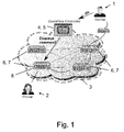
- FIG. 1 this figure illustrates a setting where a path (as illustrated by the dashed lines) between a verifier 1 and a prover 2 traverses a network domain 3 that is governed by an SDN controller 4, operated as an OpenFlow controller 5. Also, a number of SDN switches 6, operated as OpenFlow switches 7, 8, are implemented within the network domain 3. It is further assumed that the OpenFlow controller 5 cooperates with the verifier 1 (which might be, e.g., the network operator) in order to ensure the security of the conducted measurements.
- the verifier 1 which might be, e.g., the network operator
- OpenFlow is only one specific protocol that may be employed and that the described embodiment may be realized with any SDN controller/switch using protocols other than OpenFlow.
- SDN's software defined networks
- virtualization technologies on switches offer immense flexibility both in terms of defining and monitoring the network state.
- the network is completely controlled by a controller entity, i.e. the OpenFlow controller 5, which communicates with network elements that also understand the OpenFlow protocol, i.e. with the OpenFlow switches 7.
- the network traffic is controlled by a set of programmable traffic forwarding rules, which map incoming packets on a switch port to the outgoing switch port within an instance of a switch (either physical or virtual).
- the OpenFlow protocol has built-in functionality for forwarding traffic.
- the controller entity in an OpenFlow network has a detailed view of the network state, which is built by exchanging control messages between the controller and various network elements, in particular OpenFlow switches.
- Fig. 1 relates to a preferred embodiment of the invention that leverages OpenFlow and enables the secure estimation of the bottleneck bandwidth of the prover 2. It is assumed that the verifier 1 measures the bottleneck bandwidth of the path to the prover 2 using the packet-pair technique. More specifically, to measure the upload bandwidth of the path to the prover 2, the verifier 1 sends two back to back request packets of small size (e.g., 40 bytes) to the prover 2. These packets contain pseudo-randomly generated payloads in order to ensure that the prover 2 cannot predict them. Within their headers these packets encapsulate a predefined flag, e.g., in the ToS (Type of Service) field. This flag serves to announce to the OpenFlow-operated switches 7 on the path to the prover 2 that the packets correspond to bandwidth measurement packets.
- ToS Type of Service
- the prover 2 Upon reception of these packets at the prover 2, the prover 2 sends two back to back large echo replies (e.g., of 1500 byte each) to the verifier 1. Since these probe reply packets are large in size, they are likely to queue at the bottleneck link, thus ensuring that their dispersion is inversely proportional to download bottleneck bandwidth of the path (as described in K. Lai, M. Baker: “Measuring link bandwidths using a deterministic model of packet delays", in Proceedings of ACM SIGCOMM 2000 ). However, generally this kind of network measurements can be severely disturbed and manipulated by the prover 2, who can artificially insert delays within the transmission of the probe reply packets in order to alter its bandwidth claims and prevent the queueing of the packets.
- the verifier 1 informs the OpenFlow controller 5 about the IP address of the prover 2 (as indicated by the solid line arrow denoted "IP").
- IP IP address
- the OpenFlow controller 5 propagates a rule to the OpenFlow switch 8 closest to the prover 2 (as indicated by the solid line arrow denoted "Enqueue Command") requesting to queue all the packets that it receives from the prover's 2 IP address, whose header contain a measurement flag.
- the OpenFlow controller 5 requests that the selected OpenFlow switch 8 forwards the packet-pair, along with their received timestamps, t 1 and t 2 , to the OpenFlow controller 5.
- the OpenFlow controller 5 automatically sends t 1 and t 2 to the verifier 1.
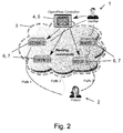
- FIG. 2 illustrates an embodiment of the present invention related to securing RTT measurements.
- the verifier 1 In order to detect such misbehavior on the side of the prover 2, the verifier 1 specially-crafts its probe request packets, which - in the context of Internet coordinate systems - are also known as ICMP (Internet Control Message Protocol) echo request packets.
- ICMP Internet Control Message Protocol
- the verifier 1 ensures that the content of the ICMP echo request packets cannot be predicted (in order to prevent rushing attacks) and inserts a flag in their header field (e.g., in the ToS field).
- the OpenFlow controller 5 Given the IP address of both the prover 2 and the verifier 1, the OpenFlow controller 5 then dynamically configures a random path (across the OpenFlow switches 6, 7) for the ICMP echo request packets issued by the verifier 1 along the path to the prover 2.
- This process is repeated for a number of independent measurements, in which the verifier 1 measures the RTT of each configured path.
- the different path may be created by the OpenFlow controller 5 installing dedicated routing commands within the OpenFlow switches 6, 7, for instance, by addressing certain switch ports by means of random-based modulo rules.
- Fig. 2 this process is illustrated for three different paths, indicated by solid lines, dashed lines, and dotted lines. It is noted that between the last OpenFlow switches 6, 7 within network domain 3 and the prover 2, in practice, the paths will include further network elements located in other network domains, which have been omitted in Fig. 2 for the sake of simplicity.
- the prover 2 cannot predict the paths that the ICMP packets will follow to the verifier 1, it is easy to see that the prover 2 cannot insert the accurate amount of delays in order to claim an RTT distance of its choice to the verifier 1 without being detected. At least when the number of paths configured by the OpenFlow controller 5 is three or more, in which case the verifier 1 may apply triangulation techniques, effectively the prover 2 will always end up claiming a number of different RTT locations. A detailed reasoning of this effect is described in S. Capkun, K.B. Rasmussen, M. Cagalj and M. Srivastava: "Secure Location Verification With Hidden and Mobile Base Stations", in IEEE Transactions on Mobile Computing, 2008 . Clearly, the bigger is the network domain 3, the larger are the amounts of OpenFlow switches 6,7, and the harder it becomes for the prover 2 to predict the path to the verifier1. Here, the prover 2 does not have to be located in the proximity of network domain 3.
Description
- The present invention relates to a method of performing secure network measurements between a verifier and a prover, wherein said verifier generates probe request packets destined to said prover and said prover echoes its probe reply packets back to said verifier.
- Furthermore, the present invention relates to a system for performing secure network measurements between a verifier and a prover, wherein said verifier is configured to generate probe request packets destined to said prover and said prover is configured to echo its probe reply packets back to said verifier.
- Network measurements are becoming crucial for the operation and security of the Internet, and of several services including for instance application-level multicast trees, content distribution and peer-to-peer (P2P) systems. Numerous tools for estimating various aspects of network performance have been proposed, among them, for instance, with regard to bandwidth measurements: Sprobe (see for reference S. Sariou, P. Gummadi and S. Gribble: "SProbe: A Fast Technique for Measuring Bottleneck Bandwidth in Uncooperative Environments", in INFOCOM, 2002), with regard to latency: traceroute (see for reference ftp://ftp.ee.lbl.gov/traceroute.tar.gz) or ping (see for reference ftp://ftp.arl.mil/pub/ping.shar), or with regard to link quality: mtr (see for reference http://www.bitwizard.nl/mtr/).
- Given the current trends in designing a secure next-generation Internet, the design of current measurement tools is showing the limits of foresight in the design/deployment of these tools:
- First of all, current network measurement tools were developed without prior security considerations, which makes them vulnerable to external and internal attacks ranging from IP spoofing to delay and rushing attacks. Since the measurements are performed end-to-end, the end-hosts might not be able to distinguish these attacks from "authentic" measurements. These security vulnerabilities might also affect the operation of the applications that make use of these measurement tools, thus increasing the gain of the attacker. Some of these problems are described in detail in M.A. Kaafar, L. Mathy, C. Barakat. K. Salamatian, T. Turletti, and W. Dabbous: "Securing Internet Coordinate Embedding Systems", in Proceedings of ACM SIGCOMM, 2007, or also in G. Karame, B. Danev, C. Bannwart, and S. Capkun: "On the Security of End-to- End Measurements based on Packet-Pair Dispersions", in IEEE Transactions on Information Forensics & Security (TIFS), 2013.
- Secondly, there are no implicit trust assumptions as current network measurement tools implicitly assume that both end-hosts are honest and behave "correctly". However, in many situations, end-hosts might have considerable incentives to cheat and increase their advantage in the network (e.g., free-riding). In this regard, references made, e.g., to A. Walters, D. Zage and C. Nita-Rotaru: "A Framework for Mitigating Attacks Against Measurement-Based Adaptation Mechanisms in Unstructured Multicast Overlay Networks", in ACM/IEEE Trans. on Networking, 2007. Indeed, if the endpoints misbehave and do not obey the measurement protocol, the estimated end-to-end metric will not reflect the authentic state of the network.
- Guang Yao et al.: "Source address validation solution with OpenFlow/NOX architecture", in 19th IEEE International Conference on Network Protocols, 17 October 2011, pages 7-12, describe a mechanism named VAVE (Virtual source Address Validation Edge) to improve the SAVI (Source Address Validation Improvements) solutions. VAVE employs OpenFlow protocol to solve source address validation problems with a global view.
- Given the above obstructions, it is an objective of the present invention to improve and further develop a method and a system for performing secure network measurements in such a way that the degree of security and reliability of the measurements, in particular in view of network entities tampering with the measurements, is enhanced.
- In accordance with the invention, the aforementioned object is accomplished by a method comprising the features of
claim 1. According to this claim such a method is characterized in that a path between said verifier and said prover traverses a network domain that includes at least one software defined network (SDN) controller and one or more SDN switches, wherein tampering of said network measurements by said prover is obviated by selectively influencing the probe request packets sent by said verifier and/or the probe reply packets sent by said prover by means of programmable packet forwarding rules said at least one SDN controller implements on said one or more SDN switches. - Furthermore, the above mentioned objective is accomplished by a system comprising the features of claim 14. According to this claim such a system is characterized in that it comprises at least one software defined network (SDN) controller and one or more SDN switches located in a network domain through which traverses a path between said verifier and said prover, wherein said at least one SDN controller is configured to implement on said one or more SDN switches programmable packet forwarding rules that are designed to obviate tampering of said network measurements by said prover by selectively influencing the probe request packets sent by said verifier and/or the probe reply packets sent by said prover.
- According to the present invention it has been recognized that a higher degree of security and reliability of the measurements can be achieved by relying on intelligence of SDN network components implemented in a network domain between the verifier and the prover. More specifically, the network measurements are conducted by making use of and with support from the smartness as provided by an SDN controller that selectively implements programmable packet forwarding rules on SDN switches within the network domain. The packet forwarding rules are designed that they selectively influence the probe request packets sent by the verifier and/or the probe reply packets sent by the prover in such a way that the prover is disabled to tamper with the measurements. This is in strong contrast to solutions according to the prevalent end-to-end principle in which network measurements are conducted without any support from the network, i.e. in scenarios in which a "naïve" network just forwards probe packets in an unaware manner.
- According to a preferred embodiment the programmable packet forwarding rules may be directed at selectively controlling the routing of the probe request packets sent by the verifier and/or the probe reply packets sent by the prover. This means that the paths the probe packets take on their way from the verifier to the prover, and reverse, may be specifically designed, for instance in such a way that the prover is not aware of the paths that are actually taken. Alternatively or additionally, the programmable packet forwarding rules may be directed at selectively controlling the temporal behavior of the probe request packets, for instance by artificially inserting packet delays the prover is not aware of.
- In some embodiments of the invention the network measurements include bottleneck bandwidth estimations. In this context it may be provided that the verifier sends two equally sized probe request packets back to back to the prover and the prover echoes two equally sized probe reply packets back to the verifier, wherein the size of the probe reply packets is larger than the size of the probe request packets. Preferably, the size of the probe reply packets is chosen to be rather large (e.g., each packet having a size of 1.500 byte) in order to generate a high probability that these packets queue at the bottleneck link.
- In accordance with a preferred embodiment the SDN controller determines the SDN switch closest to the prover and propagates a packet forwarding rule to that SDN switch, which instructs that SDN switch to queue all probe reply packets that SDN switch receives from the prover. In other words, any delay, which probe requests that are received by that configured SDN switch may have, is removed, i.e. that configured SDN switch sends out the probe packets back to back.
- In addition, the arrival times t1, t2 of the two probe reply packets at that configured SDN switch may be reported to the verifier. For instance, the SDN controller may request that the configured SDN switch forwards received probe packet-pairs, along with their received timestamps, t1 and t2, to the SDN controller, which may then automatically send t1 and t2 to the verifier.
- According to a preferred embodiment it may be provided that the verifier, upon receiving the two probe reply packets from the prover, compares the observed dispersion between the two probe reply packets against the arrival times t1, t2 of the two probe reply packets at that SDN switch located closest to prover and having been programmed with the enqueue command, as described above. In case the time difference between t1 and t2 is smaller than or equals the measured dispersion, the verifier knows for sure that the bottleneck link is located somewhere within the network domain between his own location and the location of the configured SDN switch and that his measurement was correct (and has not been tampered by the prover). Otherwise, the verifier knows that the bottleneck link is somewhere beyond the configured SDN switch, and the verifier can at least determine a lower bound of the bandwidth.
- In order to enable the SDN controller to support the network measurements conducted by the verifier, embodiments of the invention require the cooperation of the verifier with the SDN controller. In particular it may be provided that the verifier informs the SDN controller of the prover's IP address, in order to enable the SDN controller to properly identifying the SDN switch closest to the prover and to properly configure this SDN switch with the enqueue command.
- Preferably, in order to ensure that the prover cannot predict the probe request packets, the probe request packets may contain pseudo-randomly generated payloads.
- In some embodiments of the invention the network measurements include RTT (Round Trip Time) measurements. In this context it may be provided that the SDN controller dynamically configures a number of random paths across that SDN switches for probe request packets issued by the verifier towards the prover. Then, the verifier may conduct independent measurements of the RTT for each configured path. The number of configured paths is chosen to be at least two, preferably three or more. In case of at least three paths and corresponding independent measurements, the verifier can apply triangulation techniques which will reveal any tampering attempts of the prover.
- In some embodiments of the present invention, the RTT measurements as described above may be used for securing Internet coordinate systems. In such cases the probe request packets may be generated in form of ICMP (Internet Control Message Protocol) echo request packets.
- As described above, the specific capabilities of SDN network elements - controller and switches - are used in accordance with embodiments of the present invention to provide enhanced security and reliability of network measurements. While some embodiments of the invention are described using OpenFlow controller and OpenFlow switches (i.e., to be more specific, SDN controller/switches using the OpenFlow protocol) as examples of SDN network elements, it will be understood that the methods of the invention may be used with any flow-based programmable controller/switch.
- There are several ways how to design and further develop the teaching of the present invention in an advantageous way. To this end it is to be referred to the patent claims subordinate to
patent claims 1 and 14 on the one hand and to the following explanation of preferred embodiments of the invention by way of example, illustrated by the drawing on the other hand. In connection with the explanation of the preferred embodiments of the invention by the aid of the drawing, generally preferred embodiments and further developments of the teaching will be explained. - In the drawing
- Fig. 1
- is a schematic view illustrating an application scenario of secure bottleneck bandwidth estimation in accordance with an embodiment of the invention, and
- Fig. 2
- is a schematic view illustrating an application scenario of secure RTT measurements in accordance with an embodiment of the invention.
- Till recently, the end-to-end principle (for reference, see J.H. Saltzer, D.P. Reed and D.D. Clark: "End-to-End Arguments in System Design", in ACM Transactions on Computer Systems, 1984) has provided a justifiable rationale for moving functions closer to the end-hosts and has shaped the way the current Internet is designed. The true leverage of the end-to-end argument was implicitly a global architecture comprising a "naive" network and "smart" applications that do not require functionality from the switching elements deployed within the network. Given this, the design of network measurements tools equally adopted the end-to-end principle.
- The present invention turns away from the end-to-end principle and proposes to perform network measurements with the help of infrastructural support from the network, thereby enhancing the security of the measurements. More specifically, the present invention makes use of intelligence provided by software defined networks (SDNs). These networks separate the "control plane" and the "data plane", and thus achieve a large degree of "network virtualization". OpenFlow (see for reference "OpenFlow-Enabling Innovation in your Network", available from http://www.openflow.org/) is one such protocol that enables the construction of SDNs in practice. OpenFlow is a data link layer communication protocol that enables an OpenFlow controler to configure paths, in software, through a number of OpenFlow-operated switches. Here, the controller issues routing rules to the switches using a secure control channel; the switches can then dynamically implement the requested routing rules on the data plane.
- Hereinafter, by making references to the embodiments of the instant invention illustrated in the figures, it is shown how SDN networks, in particular OpenFlow-operated networks, can strengthen the security of bottleneck bandwidth estimation processes and of RTT measurements. In connection with the illustrated embodiments the extent to which SDNs (and OpenFlow-operated switches) can help in securing network measurements is described, thereby focusing on securing end-to-end bottleneck bandwidth estimations and on securing end-to-end RTT measurements.
- First, the underlying system and attacker model is outlined as follows:
- While they might be different in purpose and technique, most active end-to-end measurement tools share a similar system model consisting of a verifier and a prover connected by a network. The verifier wants to measure and verify the end-to-end performance of the path to the prover. The verifier actively generates probe packets - hereinafter denoted probe request packets - destined to the prover, who appropriately echoes back its probe packets - hereinafter denoted probe reply packets - to the verifier. The verifier then estimates the performance of the end-to-end path to the prover by extracting and analyzing the probe packets' arrival times depending on the measurement technique in question.
- While an external attacker can spoof the IP address of the prover and issue back replies on its behalf (see, for instance, B. Harris and R. Hunt: "TCP/IP security threats and attack methods", in Computer Communications, 1999), untrusted provers constitute the core of the present underlying internal attacker model. Untrusted provers denote those hosts involved in the measurement process, but they are not trusted by the verifier to correctly execute the measurement steps. Untrusted provers can intentionally manipulate the sending time of their reply probes and claim a measurement value of their choice.
- Referring now to
Fig. 1 , this figure illustrates a setting where a path (as illustrated by the dashed lines) between averifier 1 and aprover 2 traverses anetwork domain 3 that is governed by an SDN controller 4, operated as an OpenFlow controller 5. Also, a number of SDN switches 6, operated as OpenFlow switches 7, 8, are implemented within thenetwork domain 3. It is further assumed that the OpenFlow controller 5 cooperates with the verifier 1 (which might be, e.g., the network operator) in order to ensure the security of the conducted measurements. - It will be easily appreciated by those skilled in the art that OpenFlow is only one specific protocol that may be employed and that the described embodiment may be realized with any SDN controller/switch using protocols other than OpenFlow. In any case, it is important to note that in contrast to conventional networks, software defined networks (SDN's), such as OpenFlow, along with virtualization technologies on switches, offer immense flexibility both in terms of defining and monitoring the network state. For example, within the OpenFlow paradigm, the network is completely controlled by a controller entity, i.e. the OpenFlow controller 5, which communicates with network elements that also understand the OpenFlow protocol, i.e. with the OpenFlow switches 7. The network traffic is controlled by a set of programmable traffic forwarding rules, which map incoming packets on a switch port to the outgoing switch port within an instance of a switch (either physical or virtual). Thus, the OpenFlow protocol has built-in functionality for forwarding traffic. At any given time, the controller entity in an OpenFlow network has a detailed view of the network state, which is built by exchanging control messages between the controller and various network elements, in particular OpenFlow switches. These capabilities of OpenFlow controllers/switches (or, more generally, of SDN controllers/switches) are used in accordance with embodiments of the present invention to enhance the security of network measurements without altering widely used network architectures or protocols.
-
Fig. 1 relates to a preferred embodiment of the invention that leverages OpenFlow and enables the secure estimation of the bottleneck bandwidth of theprover 2. It is assumed that theverifier 1 measures the bottleneck bandwidth of the path to theprover 2 using the packet-pair technique. More specifically, to measure the upload bandwidth of the path to theprover 2, theverifier 1 sends two back to back request packets of small size (e.g., 40 bytes) to theprover 2. These packets contain pseudo-randomly generated payloads in order to ensure that theprover 2 cannot predict them. Within their headers these packets encapsulate a predefined flag, e.g., in the ToS (Type of Service) field. This flag serves to announce to the OpenFlow-operated switches 7 on the path to theprover 2 that the packets correspond to bandwidth measurement packets. - Upon reception of these packets at the
prover 2, theprover 2 sends two back to back large echo replies (e.g., of 1500 byte each) to theverifier 1. Since these probe reply packets are large in size, they are likely to queue at the bottleneck link, thus ensuring that their dispersion is inversely proportional to download bottleneck bandwidth of the path (as described in K. Lai, M. Baker: "Measuring link bandwidths using a deterministic model of packet delays", in Proceedings of ACM SIGCOMM 2000). However, generally this kind of network measurements can be severely disturbed and manipulated by theprover 2, who can artificially insert delays within the transmission of the probe reply packets in order to alter its bandwidth claims and prevent the queueing of the packets. - To ensure that the
prover 2 does not tamper with the measurements, theverifier 1 informs the OpenFlow controller 5 about the IP address of the prover 2 (as indicated by the solid line arrow denoted "IP"). The OpenFlow controller 5 then propagates a rule to theOpenFlow switch 8 closest to the prover 2 (as indicated by the solid line arrow denoted "Enqueue Command") requesting to queue all the packets that it receives from the prover's 2 IP address, whose header contain a measurement flag. - In addition, the OpenFlow controller 5 requests that the selected
OpenFlow switch 8 forwards the packet-pair, along with their received timestamps, t1 and t2, to the OpenFlow controller 5. The OpenFlow controller 5 automatically sends t1 and t2 to theverifier 1. - Let disp denote the dispersion between the packets measured by the
verifier 1, and let d = (t2 - t1 ). Here, two cases emerge: - d <= disp. In this case, the
verifier 1 can be certain that the measurement is correct since the bottleneck link is located after theOpenFlow switch 8, i.e. somewhere on the path between theOpenFlow switch 8 and theverifier 1. - disp < d. In this case, the bottleneck link is before the
OpenFlow switch 8 and theverifier 1 can at least measure (on the basis of the measured dispersion d) a lower bound on the bandwidth of theprover 2. - Given this, the closer (in number of hops) is the
prover 2 to thenetwork domain 3, the more accurate is the estimate acquired by theverifier 1. That is, the smaller is the number of hops that separate theprover 2 from theoutermost OpenFlow switch 8, the higher is the probability that the bottleneck link is located after theOpenFlow switch 8, i.e. within thenetwork domain 3 itself. This conforms with recent studies that show that bottleneck links typically coexist within inter-domains links (see for reference N. Hu, L.E. Li, Z.M. Mao, P. Steenkiste, and J. Wang: "A Measurement Study of Internet Bottlenecks", in Proceedings of INFOCOM, 2005). - Referring now to
Fig. 2 , in which like reference characters generally refer to the same parts and components as inFig. 1 , this figure illustrates an embodiment of the present invention related to securing RTT measurements. - In this regard it is referred to M.A. Kaafar, L. Mathy, T. Turletti, and W. Dabbous: "Virtual Networks under Attack: Disrupting Internet Coordinate Systems", in Proceedings of CoNext, 2006., in which authors propose the reliance on trusted surveyor nodes to secure Internet coordinate systems. In connection with the embodiment illustrated in
Fig. 2 it is shown that SDNs can also be used to secure such Internet coordinate systems by detecting delay attacks on RTT measurements. In this context it is assumed that theprover 2 is interested in claiming a specific RTT distance to theverifier 1, e.g., in order to be optimally placed in a content distribution tree. - In order to detect such misbehavior on the side of the
prover 2, theverifier 1 specially-crafts its probe request packets, which - in the context of Internet coordinate systems - are also known as ICMP (Internet Control Message Protocol) echo request packets. In particular, theverifier 1 ensures that the content of the ICMP echo request packets cannot be predicted (in order to prevent rushing attacks) and inserts a flag in their header field (e.g., in the ToS field). Given the IP address of both theprover 2 and theverifier 1, the OpenFlow controller 5 then dynamically configures a random path (across the OpenFlow switches 6, 7) for the ICMP echo request packets issued by theverifier 1 along the path to theprover 2. This process is repeated for a number of independent measurements, in which theverifier 1 measures the RTT of each configured path. The different path may be created by the OpenFlow controller 5 installing dedicated routing commands within the OpenFlow switches 6, 7, for instance, by addressing certain switch ports by means of random-based modulo rules. - In
Fig. 2 , this process is illustrated for three different paths, indicated by solid lines, dashed lines, and dotted lines. It is noted that between the last OpenFlow switches 6, 7 withinnetwork domain 3 and theprover 2, in practice, the paths will include further network elements located in other network domains, which have been omitted inFig. 2 for the sake of simplicity. - Since the
prover 2 cannot predict the paths that the ICMP packets will follow to theverifier 1, it is easy to see that theprover 2 cannot insert the accurate amount of delays in order to claim an RTT distance of its choice to theverifier 1 without being detected. At least when the number of paths configured by the OpenFlow controller 5 is three or more, in which case theverifier 1 may apply triangulation techniques, effectively theprover 2 will always end up claiming a number of different RTT locations. A detailed reasoning of this effect is described in S. Capkun, K.B. Rasmussen, M. Cagalj and M. Srivastava: "Secure Location Verification With Hidden and Mobile Base Stations", in IEEE Transactions on Mobile Computing, 2008. Clearly, the bigger is thenetwork domain 3, the larger are the amounts of OpenFlow switches 6,7, and the harder it becomes for theprover 2 to predict the path to the verifier1. Here, theprover 2 does not have to be located in the proximity ofnetwork domain 3. - Many modifications and other embodiments of the invention set forth herein will come to mind the one skilled in the art to which the invention pertains having the benefit of the teachings presented in the foregoing description and the associated drawings. Therefore, it is to be understood that the invention is not to be limited to the specific embodiments disclosed and that the scope of the invention is defined by the appended claims. Although specific terms are employed herein, they are used in a generic and descriptive sense only and not for purposes of limitation.
Claims (15)
- Method of performing secure network measurements between a verifier (1) and a prover (2), wherein said verifier (1) generates probe request packets destined to said prover (2) and said prover (2) echoes its probe reply packets back to said verifier (1),
characterized i n that a path between said verifier (1) and said prover (2) traverses a network domain (3) that includes at least one software defined network (SDN) controller (4, 5) and one or more SDN switches (6, 7, 8), wherein tampering of said network measurements by said prover (2) is obviated by selectively influencing the probe request packets sent by said verifier (1) and/or the probe reply packets sent by said prover (2) by means of programmable packet forwarding rules said at least one SDN controller (4, 5) implements on said one or more SDN switches (6, 7, 8). - Method according to claim 1, wherein said programmable packet forwarding rules are directed at selectively controlling the routing and/or the temporal behavior of the probe request packets sent by said verifier (1) and/or the probe reply packets sent by said prover (2).
- Method according to claim 1 or 2, wherein said network measurements include bottleneck bandwidth estimations.
- Method according to any of claims 1 to 3, wherein said verifier (1) sends two equally sized probe request packets back to back to said prover (2) and said prover (2) echoes two equally sized probe reply packets back to said verifier (1), wherein the size of said probe reply packets is larger than the size of said probe request packets.
- Method according to any of claims 1 to 4, wherein said SDN controller (4, 5) propagates a packet forwarding rule to the SDN switch (8) closest to said prover (2) that instructs said SDN switch (8) to queue all probe reply packets said SDN switch (8) receives from said prover (2).
- Method according to claim 5, wherein the arrival times t1, t2 of the two probe reply packets at said closest SDN switch (8) are reported to said verifier (1).
- Method according to claim 6, wherein said verifier (1), upon receiving the two probe reply packets from said prover (2), compares the observed dispersion between the two probe reply packets against the arrival times t1, t2 of the two probe reply packets at said closest SDN switch (8).
- Method according to any of claims 1 to 7, wherein said verifier (1) informs said SDN controller (4, 5) of said prover's (2) IP address.
- Method according to any of claims 1 to 8, wherein the probe request packets contain pseudo-randomly generated payloads, and/or
wherein said network measurements include RTT (Round Trip Time) measurements. - Method according to any of claims 1 to 9, wherein said SDN controller (4, 5) dynamically configures a number of random paths across said SDN switches (6, 7) for probe request packets issued by said verifier (1) towards said prover (2).
- Method according to claim 10 wherein said verifier (1) conducts independent measurements of the RTT for each configured path.
- Method according to claim 10 or 11, wherein the number of configured paths is chosen to be at least two, preferably three or more.
- Method according to any of claims 1 to 12, wherein the probe request packets are generated in form of ICMP (Internet Control Message Protocol) echo request packets, and/or,
wherein said SDN controller (4, 5) and said SDN switches (6, 7) are configured to use the OpenFlow protocol. - System for performing secure network measurements between a verifier (1) and a prover (2), wherein said verifier (1) is configured to generate probe request packets destined to said prover (2) and said prover (2) is configured to echo its probe reply packets back to said verifier (1),
characterized i n that the system comprises
at least one software defined network (SDN) controller (4, 5) and one or more SDN switches (6, 7, 8) located in a network domain (3) through which traverses a path between said verifier (1) and said prover (2),
wherein said at least one SDN controller (4, 5) is configured to implement on said one or more SDN switches (6, 7, 8) programmable packet forwarding rules that are designed to obviate tampering of said network measurements by said prover (2) by selectively influencing the probe request packets sent by said verifier (1) and/or the probe reply packets sent by said prover (2). - System according to claim 14, wherein said SDN controller (4, 5) and said SDN switches (6, 7, 8) are configured to use the OpenFlow protocol.
Priority Applications (1)
| Application Number | Priority Date | Filing Date | Title |
|---|---|---|---|
| EP14711690.9A EP2959639B1 (en) | 2013-02-21 | 2014-02-21 | Securing network measurements using openflow |
Applications Claiming Priority (3)
| Application Number | Priority Date | Filing Date | Title |
|---|---|---|---|
| EP13156085 | 2013-02-21 | ||
| EP14711690.9A EP2959639B1 (en) | 2013-02-21 | 2014-02-21 | Securing network measurements using openflow |
| PCT/EP2014/053448 WO2014128265A1 (en) | 2013-02-21 | 2014-02-21 | Securing network measurements using openflow |
Publications (2)
| Publication Number | Publication Date |
|---|---|
| EP2959639A1 EP2959639A1 (en) | 2015-12-30 |
| EP2959639B1 true EP2959639B1 (en) | 2016-08-17 |
Family
ID=50343735
Family Applications (1)
| Application Number | Title | Priority Date | Filing Date |
|---|---|---|---|
| EP14711690.9A Not-in-force EP2959639B1 (en) | 2013-02-21 | 2014-02-21 | Securing network measurements using openflow |
Country Status (3)
| Country | Link |
|---|---|
| US (1) | US9531617B2 (en) |
| EP (1) | EP2959639B1 (en) |
| WO (1) | WO2014128265A1 (en) |
Families Citing this family (17)
| Publication number | Priority date | Publication date | Assignee | Title |
|---|---|---|---|---|
| US9794244B2 (en) | 2013-08-06 | 2017-10-17 | Nec Corporation | Method for operating a network and a network |
| WO2015040624A1 (en) * | 2013-09-18 | 2015-03-26 | Hewlett-Packard Development Company, L.P. | Monitoring network performance characteristics |
| US9787559B1 (en) * | 2014-03-28 | 2017-10-10 | Juniper Networks, Inc. | End-to-end monitoring of overlay networks providing virtualized network services |
| CN104717108B (en) * | 2015-03-30 | 2018-04-06 | 北京邮电大学 | Network bottleneck Bandwidth Measurement Method based on active measurement and inter-packet gap model |
| US10015115B2 (en) * | 2015-06-01 | 2018-07-03 | Ciena Corporation | Software defined networking service control systems and methods of remote services |
| US20170012900A1 (en) * | 2015-07-08 | 2017-01-12 | Infinera Corporation | Systems, methods, and apparatus for verification of a network path |
| US9438478B1 (en) * | 2015-11-13 | 2016-09-06 | International Business Machines Corporation | Using an SDN controller to automatically test cloud performance |
| US10033660B2 (en) | 2016-03-01 | 2018-07-24 | Sprint Communications Company L.P. | Software defined network (SDN) quality-of-service (QoS) |
| US9967257B2 (en) | 2016-03-16 | 2018-05-08 | Sprint Communications Company L.P. | Software defined network (SDN) application integrity |
| US10511513B2 (en) | 2016-09-29 | 2019-12-17 | Microsoft Technology Licensing, Llc | Ping pair technique for detecting wireless congestion |
| WO2018108246A1 (en) * | 2016-12-13 | 2018-06-21 | NEC Laboratories Europe GmbH | Method and software defined network controller for performing round-trip time determination between a source element and a target element |
| KR102427834B1 (en) * | 2017-05-22 | 2022-08-02 | 삼성전자주식회사 | Method and apparatus for network quality management |
| US11005777B2 (en) | 2018-07-10 | 2021-05-11 | At&T Intellectual Property I, L.P. | Software defined prober |
| US10791023B2 (en) | 2018-08-09 | 2020-09-29 | At&T Intellectual Property I, L.P. | System and method for activating a network node |
| KR102622252B1 (en) * | 2019-05-27 | 2024-01-08 | 삼성에스디에스 주식회사 | Apparatus and method for transmitting contents |
| US11323312B1 (en) | 2020-11-25 | 2022-05-03 | Juniper Networks, Inc. | Software-defined network monitoring and fault localization |
| CN115567377A (en) * | 2021-06-30 | 2023-01-03 | 中兴通讯股份有限公司 | Path diagnosis method and system in SDN hybrid overlay network |
Citations (2)
| Publication number | Priority date | Publication date | Assignee | Title |
|---|---|---|---|---|
| EP1737179A1 (en) * | 2005-06-20 | 2006-12-27 | Thomson Licensing | Method and devices for secure measurements of time-based distance between two devices |
| US20130010600A1 (en) * | 2011-07-08 | 2013-01-10 | Telefonaktiebolaget L M Ericsson (Publ) | Controller Driven OAM for OpenFlow |
Family Cites Families (1)
| Publication number | Priority date | Publication date | Assignee | Title |
|---|---|---|---|---|
| US9432966B2 (en) * | 2011-12-08 | 2016-08-30 | Nokia Technologies Oy | Method, apparatus, and computer program product for secure distance bounding based on direction measurement |
-
2014
- 2014-02-21 US US14/766,982 patent/US9531617B2/en active Active
- 2014-02-21 EP EP14711690.9A patent/EP2959639B1/en not_active Not-in-force
- 2014-02-21 WO PCT/EP2014/053448 patent/WO2014128265A1/en active Application Filing
Patent Citations (2)
| Publication number | Priority date | Publication date | Assignee | Title |
|---|---|---|---|---|
| EP1737179A1 (en) * | 2005-06-20 | 2006-12-27 | Thomson Licensing | Method and devices for secure measurements of time-based distance between two devices |
| US20130010600A1 (en) * | 2011-07-08 | 2013-01-10 | Telefonaktiebolaget L M Ericsson (Publ) | Controller Driven OAM for OpenFlow |
Also Published As
| Publication number | Publication date |
|---|---|
| EP2959639A1 (en) | 2015-12-30 |
| US9531617B2 (en) | 2016-12-27 |
| US20160014007A1 (en) | 2016-01-14 |
| WO2014128265A1 (en) | 2014-08-28 |
Similar Documents
| Publication | Publication Date | Title |
|---|---|---|
| EP2959639B1 (en) | Securing network measurements using openflow | |
| US11228519B1 (en) | Detection of latency, packet drops, and network hops through a TCP tunnel using ICMP and UDP probes | |
| Cui et al. | On the fingerprinting of software-defined networks | |
| US8024478B2 (en) | Identifying network path including network proxies | |
| Zhang et al. | Low-Rate TCP-Targeted DoS Attack Disrupts Internet Routing. | |
| US8667585B2 (en) | Transmission control protocol flooding attack prevention method and apparatus | |
| US9503384B1 (en) | Estimating network capacity and network bandwidth without server instrumentation | |
| US11425015B2 (en) | Accurate differential traceroute latency calculation between hops | |
| US9641430B2 (en) | Verifying data plane paths based on a validated secure control plane | |
| François et al. | Network security through software defined networking: a survey | |
| US11546240B2 (en) | Proactively detecting failure points in a network | |
| US20180176248A1 (en) | Anycast-based spoofed traffic detection and mitigation | |
| US11637766B2 (en) | Detection of network hops and latency through an opaque tunnel and detection misconfiguration of tunnels | |
| US11863415B2 (en) | Determining endpoint and application behavior for monitoring user experience | |
| Al‐Najjar et al. | Network traffic control for multi‐homed end‐hosts via SDN | |
| US20220286424A1 (en) | Selection of an egress ip address for egress traffic of a distributed cloud computing network | |
| Chakravarty et al. | Identifying proxy nodes in a Tor anonymization circuit | |
| US11784904B2 (en) | Adaptive tracing with a reduced number of probes to avoid firewall issues | |
| CN109067608A (en) | A method of measuring and calculating IP packet is from equipment to hop count public network gateway | |
| US11770319B2 (en) | TCP traceroute using RST and SYN-ACK to determine destination reachability | |
| US11671438B2 (en) | Detection of latency, packet drops, and network hops through a tunnel by tracing hops therein | |
| US11949578B2 (en) | Adaptive probing to discover a protocol for network tracing | |
| Karame | Towards trustworthy network measurements | |
| US20160337222A1 (en) | Reliable Network Probing Session | |
| Sulaeman | A highly-available multiple region multi-access edge computing platform with traffic failover |
Legal Events
| Date | Code | Title | Description |
|---|---|---|---|
| PUAI | Public reference made under article 153(3) epc to a published international application that has entered the european phase |
Free format text: ORIGINAL CODE: 0009012 |
|
| 17P | Request for examination filed |
Effective date: 20150618 |
|
| AK | Designated contracting states |
Kind code of ref document: A1 Designated state(s): AL AT BE BG CH CY CZ DE DK EE ES FI FR GB GR HR HU IE IS IT LI LT LU LV MC MK MT NL NO PL PT RO RS SE SI SK SM TR |
|
| AX | Request for extension of the european patent |
Extension state: BA ME |
|
| RIN1 | Information on inventor provided before grant (corrected) |
Inventor name: KARAME, GHASSAN |
|
| GRAP | Despatch of communication of intention to grant a patent |
Free format text: ORIGINAL CODE: EPIDOSNIGR1 |
|
| DAX | Request for extension of the european patent (deleted) | ||
| INTG | Intention to grant announced |
Effective date: 20160420 |
|
| GRAS | Grant fee paid |
Free format text: ORIGINAL CODE: EPIDOSNIGR3 |
|
| GRAA | (expected) grant |
Free format text: ORIGINAL CODE: 0009210 |
|
| RAP1 | Party data changed (applicant data changed or rights of an application transferred) |
Owner name: NEC CORPORATION |
|
| AK | Designated contracting states |
Kind code of ref document: B1 Designated state(s): AL AT BE BG CH CY CZ DE DK EE ES FI FR GB GR HR HU IE IS IT LI LT LU LV MC MK MT NL NO PL PT RO RS SE SI SK SM TR |
|
| REG | Reference to a national code |
Ref country code: GB Ref legal event code: FG4D |
|
| REG | Reference to a national code |
Ref country code: CH Ref legal event code: EP |
|
| REG | Reference to a national code |
Ref country code: IE Ref legal event code: FG4D |
|
| REG | Reference to a national code |
Ref country code: AT Ref legal event code: REF Ref document number: 821981 Country of ref document: AT Kind code of ref document: T Effective date: 20160915 |
|
| REG | Reference to a national code |
Ref country code: DE Ref legal event code: R096 Ref document number: 602014003140 Country of ref document: DE |
|
| REG | Reference to a national code |
Ref country code: NL Ref legal event code: MP Effective date: 20160817 |
|
| REG | Reference to a national code |
Ref country code: LT Ref legal event code: MG4D |
|
| REG | Reference to a national code |
Ref country code: AT Ref legal event code: MK05 Ref document number: 821981 Country of ref document: AT Kind code of ref document: T Effective date: 20160817 |
|
| PG25 | Lapsed in a contracting state [announced via postgrant information from national office to epo] |
Ref country code: IT Free format text: LAPSE BECAUSE OF FAILURE TO SUBMIT A TRANSLATION OF THE DESCRIPTION OR TO PAY THE FEE WITHIN THE PRESCRIBED TIME-LIMIT Effective date: 20160817 Ref country code: NO Free format text: LAPSE BECAUSE OF FAILURE TO SUBMIT A TRANSLATION OF THE DESCRIPTION OR TO PAY THE FEE WITHIN THE PRESCRIBED TIME-LIMIT Effective date: 20161117 Ref country code: HR Free format text: LAPSE BECAUSE OF FAILURE TO SUBMIT A TRANSLATION OF THE DESCRIPTION OR TO PAY THE FEE WITHIN THE PRESCRIBED TIME-LIMIT Effective date: 20160817 Ref country code: RS Free format text: LAPSE BECAUSE OF FAILURE TO SUBMIT A TRANSLATION OF THE DESCRIPTION OR TO PAY THE FEE WITHIN THE PRESCRIBED TIME-LIMIT Effective date: 20160817 Ref country code: LT Free format text: LAPSE BECAUSE OF FAILURE TO SUBMIT A TRANSLATION OF THE DESCRIPTION OR TO PAY THE FEE WITHIN THE PRESCRIBED TIME-LIMIT Effective date: 20160817 Ref country code: NL Free format text: LAPSE BECAUSE OF FAILURE TO SUBMIT A TRANSLATION OF THE DESCRIPTION OR TO PAY THE FEE WITHIN THE PRESCRIBED TIME-LIMIT Effective date: 20160817 Ref country code: FI Free format text: LAPSE BECAUSE OF FAILURE TO SUBMIT A TRANSLATION OF THE DESCRIPTION OR TO PAY THE FEE WITHIN THE PRESCRIBED TIME-LIMIT Effective date: 20160817 |
|
| REG | Reference to a national code |
Ref country code: FR Ref legal event code: PLFP Year of fee payment: 4 |
|
| PG25 | Lapsed in a contracting state [announced via postgrant information from national office to epo] |
Ref country code: GR Free format text: LAPSE BECAUSE OF FAILURE TO SUBMIT A TRANSLATION OF THE DESCRIPTION OR TO PAY THE FEE WITHIN THE PRESCRIBED TIME-LIMIT Effective date: 20161118 Ref country code: PL Free format text: LAPSE BECAUSE OF FAILURE TO SUBMIT A TRANSLATION OF THE DESCRIPTION OR TO PAY THE FEE WITHIN THE PRESCRIBED TIME-LIMIT Effective date: 20160817 Ref country code: AT Free format text: LAPSE BECAUSE OF FAILURE TO SUBMIT A TRANSLATION OF THE DESCRIPTION OR TO PAY THE FEE WITHIN THE PRESCRIBED TIME-LIMIT Effective date: 20160817 Ref country code: LV Free format text: LAPSE BECAUSE OF FAILURE TO SUBMIT A TRANSLATION OF THE DESCRIPTION OR TO PAY THE FEE WITHIN THE PRESCRIBED TIME-LIMIT Effective date: 20160817 Ref country code: ES Free format text: LAPSE BECAUSE OF FAILURE TO SUBMIT A TRANSLATION OF THE DESCRIPTION OR TO PAY THE FEE WITHIN THE PRESCRIBED TIME-LIMIT Effective date: 20160817 Ref country code: PT Free format text: LAPSE BECAUSE OF FAILURE TO SUBMIT A TRANSLATION OF THE DESCRIPTION OR TO PAY THE FEE WITHIN THE PRESCRIBED TIME-LIMIT Effective date: 20161219 Ref country code: SE Free format text: LAPSE BECAUSE OF FAILURE TO SUBMIT A TRANSLATION OF THE DESCRIPTION OR TO PAY THE FEE WITHIN THE PRESCRIBED TIME-LIMIT Effective date: 20160817 |
|
| PG25 | Lapsed in a contracting state [announced via postgrant information from national office to epo] |
Ref country code: RO Free format text: LAPSE BECAUSE OF FAILURE TO SUBMIT A TRANSLATION OF THE DESCRIPTION OR TO PAY THE FEE WITHIN THE PRESCRIBED TIME-LIMIT Effective date: 20160817 Ref country code: EE Free format text: LAPSE BECAUSE OF FAILURE TO SUBMIT A TRANSLATION OF THE DESCRIPTION OR TO PAY THE FEE WITHIN THE PRESCRIBED TIME-LIMIT Effective date: 20160817 |
|
| REG | Reference to a national code |
Ref country code: DE Ref legal event code: R097 Ref document number: 602014003140 Country of ref document: DE |
|
| PG25 | Lapsed in a contracting state [announced via postgrant information from national office to epo] |
Ref country code: CZ Free format text: LAPSE BECAUSE OF FAILURE TO SUBMIT A TRANSLATION OF THE DESCRIPTION OR TO PAY THE FEE WITHIN THE PRESCRIBED TIME-LIMIT Effective date: 20160817 Ref country code: BE Free format text: LAPSE BECAUSE OF FAILURE TO SUBMIT A TRANSLATION OF THE DESCRIPTION OR TO PAY THE FEE WITHIN THE PRESCRIBED TIME-LIMIT Effective date: 20160817 Ref country code: BG Free format text: LAPSE BECAUSE OF FAILURE TO SUBMIT A TRANSLATION OF THE DESCRIPTION OR TO PAY THE FEE WITHIN THE PRESCRIBED TIME-LIMIT Effective date: 20161117 Ref country code: SM Free format text: LAPSE BECAUSE OF FAILURE TO SUBMIT A TRANSLATION OF THE DESCRIPTION OR TO PAY THE FEE WITHIN THE PRESCRIBED TIME-LIMIT Effective date: 20160817 Ref country code: SK Free format text: LAPSE BECAUSE OF FAILURE TO SUBMIT A TRANSLATION OF THE DESCRIPTION OR TO PAY THE FEE WITHIN THE PRESCRIBED TIME-LIMIT Effective date: 20160817 Ref country code: DK Free format text: LAPSE BECAUSE OF FAILURE TO SUBMIT A TRANSLATION OF THE DESCRIPTION OR TO PAY THE FEE WITHIN THE PRESCRIBED TIME-LIMIT Effective date: 20160817 |
|
| PLBE | No opposition filed within time limit |
Free format text: ORIGINAL CODE: 0009261 |
|
| STAA | Information on the status of an ep patent application or granted ep patent |
Free format text: STATUS: NO OPPOSITION FILED WITHIN TIME LIMIT |
|
| 26N | No opposition filed |
Effective date: 20170518 |
|
| PG25 | Lapsed in a contracting state [announced via postgrant information from national office to epo] |
Ref country code: SI Free format text: LAPSE BECAUSE OF FAILURE TO SUBMIT A TRANSLATION OF THE DESCRIPTION OR TO PAY THE FEE WITHIN THE PRESCRIBED TIME-LIMIT Effective date: 20160817 |
|
| PG25 | Lapsed in a contracting state [announced via postgrant information from national office to epo] |
Ref country code: MC Free format text: LAPSE BECAUSE OF FAILURE TO SUBMIT A TRANSLATION OF THE DESCRIPTION OR TO PAY THE FEE WITHIN THE PRESCRIBED TIME-LIMIT Effective date: 20160817 |
|
| REG | Reference to a national code |
Ref country code: CH Ref legal event code: PL |
|
| PG25 | Lapsed in a contracting state [announced via postgrant information from national office to epo] |
Ref country code: CH Free format text: LAPSE BECAUSE OF NON-PAYMENT OF DUE FEES Effective date: 20170228 Ref country code: LI Free format text: LAPSE BECAUSE OF NON-PAYMENT OF DUE FEES Effective date: 20170228 |
|
| REG | Reference to a national code |
Ref country code: IE Ref legal event code: MM4A |
|
| PG25 | Lapsed in a contracting state [announced via postgrant information from national office to epo] |
Ref country code: LU Free format text: LAPSE BECAUSE OF NON-PAYMENT OF DUE FEES Effective date: 20170221 |
|
| REG | Reference to a national code |
Ref country code: FR Ref legal event code: PLFP Year of fee payment: 5 |
|
| PG25 | Lapsed in a contracting state [announced via postgrant information from national office to epo] |
Ref country code: IE Free format text: LAPSE BECAUSE OF NON-PAYMENT OF DUE FEES Effective date: 20170221 |
|
| PG25 | Lapsed in a contracting state [announced via postgrant information from national office to epo] |
Ref country code: MT Free format text: LAPSE BECAUSE OF NON-PAYMENT OF DUE FEES Effective date: 20170221 |
|
| PG25 | Lapsed in a contracting state [announced via postgrant information from national office to epo] |
Ref country code: AL Free format text: LAPSE BECAUSE OF FAILURE TO SUBMIT A TRANSLATION OF THE DESCRIPTION OR TO PAY THE FEE WITHIN THE PRESCRIBED TIME-LIMIT Effective date: 20160817 |
|
| PG25 | Lapsed in a contracting state [announced via postgrant information from national office to epo] |
Ref country code: HU Free format text: LAPSE BECAUSE OF FAILURE TO SUBMIT A TRANSLATION OF THE DESCRIPTION OR TO PAY THE FEE WITHIN THE PRESCRIBED TIME-LIMIT; INVALID AB INITIO Effective date: 20140221 |
|
| PG25 | Lapsed in a contracting state [announced via postgrant information from national office to epo] |
Ref country code: CY Free format text: LAPSE BECAUSE OF FAILURE TO SUBMIT A TRANSLATION OF THE DESCRIPTION OR TO PAY THE FEE WITHIN THE PRESCRIBED TIME-LIMIT Effective date: 20160817 |
|
| PG25 | Lapsed in a contracting state [announced via postgrant information from national office to epo] |
Ref country code: MK Free format text: LAPSE BECAUSE OF FAILURE TO SUBMIT A TRANSLATION OF THE DESCRIPTION OR TO PAY THE FEE WITHIN THE PRESCRIBED TIME-LIMIT Effective date: 20160817 |
|
| PG25 | Lapsed in a contracting state [announced via postgrant information from national office to epo] |
Ref country code: TR Free format text: LAPSE BECAUSE OF FAILURE TO SUBMIT A TRANSLATION OF THE DESCRIPTION OR TO PAY THE FEE WITHIN THE PRESCRIBED TIME-LIMIT Effective date: 20160817 |
|
| PG25 | Lapsed in a contracting state [announced via postgrant information from national office to epo] |
Ref country code: IS Free format text: LAPSE BECAUSE OF FAILURE TO SUBMIT A TRANSLATION OF THE DESCRIPTION OR TO PAY THE FEE WITHIN THE PRESCRIBED TIME-LIMIT Effective date: 20161217 |
|
| PGFP | Annual fee paid to national office [announced via postgrant information from national office to epo] |
Ref country code: FR Payment date: 20210113 Year of fee payment: 8 |
|
| PGFP | Annual fee paid to national office [announced via postgrant information from national office to epo] |
Ref country code: DE Payment date: 20210209 Year of fee payment: 8 Ref country code: GB Payment date: 20210210 Year of fee payment: 8 |
|
| REG | Reference to a national code |
Ref country code: DE Ref legal event code: R079 Ref document number: 602014003140 Country of ref document: DE Free format text: PREVIOUS MAIN CLASS: H04L0012260000 Ipc: H04L0043000000 |
|
| REG | Reference to a national code |
Ref country code: DE Ref legal event code: R119 Ref document number: 602014003140 Country of ref document: DE |
|
| GBPC | Gb: european patent ceased through non-payment of renewal fee |
Effective date: 20220221 |
|
| PG25 | Lapsed in a contracting state [announced via postgrant information from national office to epo] |
Ref country code: FR Free format text: LAPSE BECAUSE OF NON-PAYMENT OF DUE FEES Effective date: 20220228 |
|
| PG25 | Lapsed in a contracting state [announced via postgrant information from national office to epo] |
Ref country code: GB Free format text: LAPSE BECAUSE OF NON-PAYMENT OF DUE FEES Effective date: 20220221 Ref country code: DE Free format text: LAPSE BECAUSE OF NON-PAYMENT OF DUE FEES Effective date: 20220901 |