EP2957917A1 - Pipetting device with housing - Google Patents
Pipetting device with housing Download PDFInfo
- Publication number
- EP2957917A1 EP2957917A1 EP15172457.2A EP15172457A EP2957917A1 EP 2957917 A1 EP2957917 A1 EP 2957917A1 EP 15172457 A EP15172457 A EP 15172457A EP 2957917 A1 EP2957917 A1 EP 2957917A1
- Authority
- EP
- European Patent Office
- Prior art keywords
- housing part
- pipetting device
- housing
- pipetting
- side walls
- Prior art date
- Legal status (The legal status is an assumption and is not a legal conclusion. Google has not performed a legal analysis and makes no representation as to the accuracy of the status listed.)
- Granted
Links
Images


Classifications
-
- G—PHYSICS
- G01—MEASURING; TESTING
- G01N—INVESTIGATING OR ANALYSING MATERIALS BY DETERMINING THEIR CHEMICAL OR PHYSICAL PROPERTIES
- G01N35/00—Automatic analysis not limited to methods or materials provided for in any single one of groups G01N1/00 - G01N33/00; Handling materials therefor
- G01N35/10—Devices for transferring samples or any liquids to, in, or from, the analysis apparatus, e.g. suction devices, injection devices
Landscapes
- General Health & Medical Sciences (AREA)
- Health & Medical Sciences (AREA)
- Life Sciences & Earth Sciences (AREA)
- Chemical & Material Sciences (AREA)
- Analytical Chemistry (AREA)
- Biochemistry (AREA)
- Physics & Mathematics (AREA)
- General Physics & Mathematics (AREA)
- Immunology (AREA)
- Pathology (AREA)
- Sampling And Sample Adjustment (AREA)
- Apparatus Associated With Microorganisms And Enzymes (AREA)
- Automatic Analysis And Handling Materials Therefor (AREA)
Abstract
Eine Pipettiervorrichtung mit Gehäuse (10), insbesondere Pipettieroboter, umfasst: einen unteren Gehäuseteil (16) mit einem Gehäuseboden (28), einer unteren Rückseite (32), einer unteren Vorderseite (30) und unteren Seitenwänden (34a, 34b), welche die untere Vorderseite (30) und die untere Rückseite (32) miteinander verbinden, wobei der untere Gehäuseteil (16) derart ausgeführt ist, dass er direkt auf einer Aufstellfläche, insbesondere einer Arbeitsfläche eines Tisches oder dergleichen, aufstellbar ist; einen oberen Gehäuseteil (14) mit einem Gehäusedach (18), einer oberen Rückseite (22), einer oberen Vorderseite (20) und oberen Seitenwänden (24a, 24b), welche die obere Vorderseite (20) und die obere Rückseite (22) miteinander verbinden; wobei der Gehäuseboden (28) wenigstens eine Auflagefläche (70) umfasst, auf der eine im Gehäuse aufgenommene Pipettiervorrichtung aufliegt; wobei der obere Gehäuseteil (14) und der untere Gehäuseteil (16) derart ausgeführt sind, dass der obere Gehäuseteil (14) unabhängig von der im unteren Gehäuseteil (16) aufgenommenen Pipettiervorrichtung auf dem unteren Gehäuseteil (16) angeordnet werden kann oder von diesem abgenommen werden kann.A pipetting device with housing (10), in particular pipetting robot, comprises: a lower housing part (16) having a housing bottom (28), a lower back (32), a lower front (30) and lower sidewalls (34a, 34b) interconnecting the lower front (30) and lower back (32) connect, wherein the lower housing part (16) is designed such that it can be placed directly on a footprint, in particular a working surface of a table or the like; an upper housing part (14) having a housing roof (18), an upper back (22), an upper front (20) and upper side walls (24a, 24b) interconnecting the upper front (20) and upper back (22) connect; wherein the housing bottom (28) comprises at least one bearing surface (70) on which a pipetting device received in the housing rests; wherein the upper housing part (14) and the lower housing part (16) are designed such that the upper housing part (14) can be arranged independently of the in the lower housing part (16) recorded pipetting on the lower housing part (16) or removed from this can be.
Description
Die Erfindung betrifft eine Pipettiervorrichtung mit Gehäuse, insbesondere einen in einem Gehäuse bzw. einer Verschalung aufgenommenen Pipettieroboter.The invention relates to a pipetting device with housing, in particular a pipetting robot accommodated in a housing or a casing.
Pipettiervorrichtungen zur automatisierten Analyse von biologischen bzw. medizinischen Proben sind üblicherweise in einem Gehäuse untergebracht, um einen beim Verarbeiten von Probenflüssigkeit weitgehend geschlossenen Arbeitsraum bereitstellen zu können. Das Gehäuse dient insbesondere dazu, dem Verdunsten von Probenflüssigkeit entgegenzuwirken durch Reduzierung von Luftströmungen im Arbeitsraum. Ferner dienen die Gehäuse auch dem Schutz von Bedienpersonen während des automatischen Verarbeitens von Proben, wenn die wenigstens eine Pipettiereinheit mit hoher Geschwindigkeit innerhalb des Arbeitsraumes hin und her bewegt wird. Schließlich können durch das Gehäuse auch Verunreinigungen der Pipettiervorrichtung gemindert bzw. verhindert werden.Pipetting devices for the automated analysis of biological or medical samples are usually housed in a housing in order to provide a largely closed during processing of sample liquid working space can. The housing serves in particular to counteract the evaporation of sample liquid by reducing air flows in the working space. Further, the housings also serve to protect operators during the automatic processing of samples when the at least one pipetting unit is reciprocated at high speed within the working space. Finally, contamination of the pipetting device can also be reduced or prevented by the housing.
Bei bisher bekannten Pipettiervorrichtungen ist das Gehäuse in der Regel so gestaltet, dass es fest mit einer Tragstruktur (Rahmenkonstruktion) der Pipettiervorrichtung verbunden ist. Üblicherweise wird das Gehäuse dadurch gebildet, dass an einer die Stabilität der Pipettiervorrichtung gewährleistenden Tragkonstruktion entsprechende Verschalungselemente, etwa in Form von wenigstens teilweise transparenten Klappen oder Platten befestigt sind. Beispiele solcher Pipettiervorrichtungen mit Gehäuse können beispielsweise in der Broschüre der Anmelderin zu ihren STARLINE Produkten gefunden werden, die im Internet zum Zeitpunkt der Einreichung dieser Anmeldung unter folgendem Link verfügbar war: http://www.hamiltonrobotics.com/fileadmin/user_upload/products/startour/MR -0805-03_STAR_LINE_web.pdfIn previously known pipetting devices, the housing is usually designed so that it is firmly connected to a support structure (frame construction) of the pipetting device. Usually, the housing is formed by fixing shuttering elements, for example in the form of at least partially transparent flaps or plates, to a support structure ensuring the stability of the pipetting device. Examples of such pipetting devices with housings can be found, for example, in Applicants' brochure for their STARLINE products, which was available on the Internet at the time of filing of this application under the following link: http://www.hamiltonrobotics.com/fileadmin/user_upload/products/ startour / MR -0805-03_STAR_LINE_web.pdf
Solche Gehäuse, die auch Teil der tragenden Struktur für die Pipettiervorrichtung sind, weisen den Nachteil auf, dass der Zugang zur Pipettiervorrichtung erschwert sein kann und dass die Montage einer solchen Pipettiervorrichtung samt Gehäuse sehr aufwändig ist.Such housings, which are also part of the supporting structure for the pipetting device, have the disadvantage that access to the pipetting device can be difficult and that the assembly of such a pipetting device together with the housing is very complicated.
Aufgabe der Erfindung ist es, eine Pipettiervorrichtung mit Gehäuse bereitzustellen, bei der die erwähnten Nachteile gemindert oder verhindert werden können.The object of the invention is to provide a pipetting device with housing, in which the mentioned disadvantages can be reduced or prevented.
Diese Aufgabe wird durch eine Pipettiervorrichtung mit Gehäuse gemäß den unabhängigen Ansprüchen gelöst. Bevorzugte weitere Merkmale der Pipettiervorrichtung mit Gehäuse sind in den abhängigen Ansprüchen enthalten.This object is achieved by a pipetting device with housing according to the independent claims. Preferred further features of the pipetting device with housing are contained in the dependent claims.
Eine Pipettiervorrichtung mit Gehäuse umfasst:
- einen unteren Gehäuseteil mit einem Gehäuseboden, einer unteren Rückseite,
- einer unteren Vorderseite und unteren Seitenwänden, welche die untere Vorderseite und die untere Rückseite miteinander verbinden, wobei der untere Gehäuseteil derart ausgeführt ist, dass er direkt auf einer Aufstellfläche, insbesondere einer Arbeitsfläche eines Tisches oder dergleichen, aufstellbar ist;
- einen oberen Gehäuseteil mit einem Gehäusedach, einer oberen Rückseite, einer oberen Vorderseite und oberen Seitenwänden, welche die obere Vorderseite und die obere Rückseite miteinander verbinden;
- wobei der Gehäuseboden wenigstens eine Auflagefläche umfasst, auf der eine im Gehäuse aufgenommene Pipettiervorrichtung aufliegt;
- wobei der obere Gehäuseteil und der untere Gehäuseteil derart ausgeführt sind, dass der obere Gehäuseteil unabhängig von der im unteren Gehäuseteil aufgenommenen Pipettiervorrichtung auf dem unteren Gehäuseteil angeordnet werden kann oder von diesem abgenommen werden kann.
- a lower housing part with a housing bottom, a lower rear side,
- a lower front side and lower side walls which connect the lower front side and the lower rear side with one another, wherein the lower housing part is designed so that it can be placed directly on a footprint, in particular a working surface of a table or the like;
- an upper housing part having a housing roof, an upper rear side, an upper front side and upper side walls connecting the upper front side and the upper rear side with each other;
- wherein the housing bottom comprises at least one bearing surface on which a pipetting device received in the housing rests;
- wherein the upper housing part and the lower housing part are designed such that the upper housing part can be arranged independently of the recorded in the lower housing part pipetting on the lower housing part or can be removed from this.
Das Gehäuse ist mit seinem untern und seinem oberen Gehäuseteil unabhängig von einer Tragstruktur der Pipettievorrichtung ausgeführt. Der obere Gehäuseteil kann in der Art einer Haube auf den unteren Gehäuseteil gesetzt werden oder von diesem abgenommen werden. Das Gehäuse ist grundsätzlich so aufgebaut, dass der obere und der untere Gehäuseteil eine selbsttragende Struktur aufweisen, so dass das Gehäuse auch ohne darin aufgenommene Pipettiervorrichtung in sich stabil ist und somit frei aufstellbar ist. Die Pipettiervorrichtung ist aufgrund der wirkenden Schwerkraft an dem unteren Gehäuseteil gelagert. Verbindungen zur gegenseitigen Stabilisierung von Pipettiervorrichtung und den beiden Gehäuseteilen sind nicht zwingend erforderlich.The housing is designed with its lower and lower housing part independent of a support structure of the pipetting device. The upper housing part can be placed in the manner of a hood on the lower housing part or removed from this. The housing is basically constructed so that the upper and the lower housing part have a self-supporting structure, so that the housing is stable even without it incorporated pipetting in itself and thus is freely deployable. The pipetting device is mounted on the lower housing part due to the force of gravity. Connections for the mutual stabilization of the pipetting device and the two housing parts are not absolutely necessary.
Die erreichte Entflechtung der Konstruktionen von Gehäuse und Pipettiervorrichtung ermöglicht die getrennte Herstellung der Pipetiervorrichtung und des Gehäuses und eine einfache Montage, im Wesentlichen durch das Anordnen der Pipettiervorrichtung in dem unteren Gehäuseteil und einem nachfolgenden Aufsetzen des oberen Gehäuseteils auf den unteren Gehäuseteil.The achieved unbundling of the housing and pipetting device constructions enables separate production of the pipetting device and the housing and easy assembly, essentially by placing the pipetting device in the lower housing part and subsequently placing the upper housing part on the lower housing part.
Es ist bevorzugt, dass die unteren Seitenwände Stirnseiten aufweisen, die dem oberen Gehäuseteil zugewandt sind und die wenigstens einen teilweise geneigt verlaufenden unteren Auflageabschnitt umfassen.It is preferred that the lower side walls have end faces which face the upper housing part and which comprise at least one partially inclined lower support section.
Ferner ist es bevorzugt, dass die oberen Seitenwände Stirnseiten aufweisen, die dem unteren Gehäuseteil zugewandt sind und die wenigstens einen teilweise geneigt verlaufenden oberen Auflageabschnitt umfassen.Furthermore, it is preferred that the upper side walls have end faces which face the lower housing part and which comprise at least one partially inclined upper support section.
Wenn an jeder Stirnseite wenigstens zwei geneigte Auflageabschnitte vorgesehen sind, die derart geneigt sind, dass sie sich in einer gedachten Verlängerung entlang der betreffenden unteren oder oberen Seitenwand in einem stumpfen Winkel scheiden, können der obere Gehäuseteil und der untere Gehäuseteil im Bereich ihrer Stirnseiten miteinander in formschlüssige Verbindung gebracht werden. Durch die geneigte Anordnung der Stirnseiten kann ein Bewegen des oberen Gehäuseteils auf dem unteren Gehäuseteil insbesondere entlang einer im Wesentlichen horizontalen und zu den Seitenwänden im Wesentlichen parallelen Richtung verhindert werden.If at least two inclined support portions are provided on each end face, which are inclined so that they divide in an imaginary extension along the respective lower or upper side wall at an obtuse angle, the upper housing part and the lower housing part in the region of their end faces with each other in positive connection can be brought. Due to the inclined arrangement of the end faces, a movement of the upper housing part on the lower housing part can be prevented, in particular along a substantially horizontal and substantially parallel to the side walls direction.
Um einer Verschiebung des oberen Gehäuseteils auf dem unteren Gehäuseteil weiter entgegenzuwirken, können am oberen Gehäuseteil und am unteren Gehäuseteil Vorsprünge und korrespondierende Ausnehmungen so vorgesehen sind, dass sie miteinander in Eingriff stehen, wenn der obere Gehäuseteil auf dem unteren Gehäuseteil angeordnet ist. Dies kann insbesondere durch Bohrungen in den unteren Seitenwänden bzw. deren Stirnseiten und korrespondierenden Stiften bzw. Zapfen in den oberen Seitenwänden bzw. deren Stirnseiten erreicht werden. Selbstverständlich kann die Anordnung von Ausnehmungen und Vorsprüngen an den oberen bzw. unteren Stirnseiten frei gewählt werden und es ist denkbar, dass an einer Stirnseite sowohl Ausnehmungen als auch Vorsprünge vorgesehen sind.In order to further counteract a displacement of the upper housing part on the lower housing part, projections and corresponding recesses may be provided on the upper housing part and the lower housing part so that they engage with each other when the upper housing part is arranged on the lower housing part. This can be achieved in particular by drilling in the lower side walls or their end faces and corresponding pins or pins in the upper side walls or their end faces. Of course, the arrangement of recesses and projections on the upper and lower end sides can be chosen freely and it is conceivable that both recesses and projections are provided on one end face.
In den unteren und den oberen Seitenwänden kann jeweils ein Ausschnitt vorgesehen sein, in dem ein die obere und untere Seitenwand verbindendes insbesondere transparentes Seitenwandelement, vorzugsweise ein Fensterelement aus Kunststoff oder Glas, aufnehmbar oder aufgenommen ist. Entlang eines Innenumfangs der Ausschnitte kann zu diesem Zweck eine Nut vorgesehen sein, in welche das Seitenwandelement aufgenommen werden kann bzw. aufgenommen ist.In each of the lower and the upper side walls, a cutout can be provided, in which a particularly transparent side wall element connecting the upper and lower side walls, preferably a window element made of plastic or glass, can be received or accommodated. Along an inner circumference of the cutouts may be provided for this purpose, a groove into which the side wall element can be received or added.
Es ist bevorzugt, dass der untere Gehäuseteil an seiner Vorderseite wenigstens ein unteres Türelement aufweist, das zwischen einer Öffnungsstellung und einer Verschlussstellung beweglich, insbesondere verschwenkbar ist, wobei vorzugsweise das untere Türelement wenigstens teilweise aus einem transparenten Material hergestellt ist.It is preferred that the lower housing part has on its front side at least one lower door element, which is movable between an open position and a closed position, in particular pivotable, wherein preferably the lower door element is at least partially made of a transparent material.
Ferner kann der obere Gehäuseteil an seiner Vorderseite wenigstens ein oberes Türelement aufweisen, das zwischen einer Öffnungsstellung und einer Verschlussstellung beweglich, insbesondere verschwenkbar ist, wobei vorzugsweise das obere Türelement wenigstens teilweise aus einem transparenten Material hergestellt ist.Furthermore, the upper housing part may have on its front side at least one upper door element, which is movable between an open position and a closed position, in particular pivotable, wherein preferably the upper door element is at least partially made of a transparent material.
Durch das obere und das untere Türelement kann ein Zugang zur Pipettiervorrichtung bereitgestellt werden, die im Gehäuse aufgenommen ist. Bei geschlossenem oberem Türelement können durch ein geöffnetes unteres Türelement Probenbehälter bzw. sogenannte Racks in die Pipettiervorrichtung eingeführt oder aus dieser entnommen werden. Das obere und das untere Türelement sind vorzugsweise um eine obere bzw. untere Schwenkachse drehbar, derart, dass das obere Türelement beim Öffnen nach oben verschwenkt wird und das untere Türelement beim Öffnen nach unten verschwenkt wird.Through the upper and the lower door member, an access to the pipetting device can be provided, which is accommodated in the housing. When the upper door element is closed, sample containers or so-called racks can be introduced or removed from the pipetting device through an opened lower door element. The upper and the lower door element are preferably rotatable about an upper or lower pivot axis, such that the upper door element is pivoted when opening upwards and the lower door element is pivoted downwards when opening.
Bei geschlossenem unteren und oberen Türelement kann ein durch das Gehäuse gebildeter geschlossener Arbeitsraum gebildet werden, in dem die Pipettiervorrichtung im Betrieb aufgenommen ist.When the lower and upper door element is closed, a closed working space formed by the housing can be formed, in which the pipetting device is received during operation.
Im Gehäuseboden können mehrere voneinander getrennte Vertiefungen vorgesehen sein, deren jeweilige Bodenfläche tiefer liegt als die Auflagefläche für die Pipettiervorrichtung.In the housing bottom a plurality of mutually separate recesses may be provided, the respective bottom surface is lower than the support surface for the pipetting device.
Dabei ist es bevorzugt, dass die Vertiefungen derart ausgeführt sind, dass in ihnen weitere dem Betrieb der Pipettiervorrichtung dienende Komponenten aufnehmbar sind, wie etwa Stromanschlusseinheit, Rechnereinheit, Lüftungseinheit und dergleichen.In this case, it is preferred that the depressions are designed in such a way that they can accommodate further components serving for the operation of the pipetting device, such as, for example, power supply unit, computer unit, ventilation unit and the like.
In der oberen oder/und der unteren Rückwand des oberen bzw. unteren Gehäuseteils können gitterartige oder schlitzartige Öffnungen vorgesehen sein.In the upper and / or the lower rear wall of the upper and lower housing part lattice-like or slot-like openings may be provided.
Vorzugsweise sind der untere Gehäuseteil und der obere Gehäuseteil aus einem Kunststoff hergestellt, vorzugsweise aus Polyurethan oder Polyurethanschaum. Da die beiden Gehäuseteile schalenartig bzw. haubenartige ausgeführt sind, können sie in einem Gussverfahren oder Schäumverfahren in einfacher Weise hergestellt werden. Die Verwendung eines Kunststoffschaums hat dabei den Vorteil, dass eine gut elektrische Isolierung erreicht wird und Gewicht eingesprart werden kann.Preferably, the lower housing part and the upper housing part are made of a plastic, preferably polyurethane or polyurethane foam. Since the two housing parts are designed shell-like or hood-like, they can be produced in a casting process or foaming in a simple manner. The use of a plastic foam has the advantage that a good electrical insulation is achieved and weight can be eingesprart.
Bevorzugt umfasst die im Gehäuse aufgenommene Pipettiervorrichtung:
- eine Aufnahmeplatte zur Aufnahme von wenigstens einem Probenbehälter;
- wenigstens eine Pipettiereinheit mit einem Pipettierkanal zum Aspirieren und Dispensieren von Probenflüssigkeit aus dem wenigstens einen Probenbehälter, wobei der Pipettierkanal in drei zueinander orthogonalen Hauptrichtungen (X, Y, Z) beweglich ist mittels Antriebseinheiten für die Bewegung entlang der Hauptrichtungen (X, Y Z),
- wobei eine mit der Aufnahmeplatte verbundene Trägerkonstruktion, an der die Pipettiereinheit gelagert ist und entlang der die Pipettiereinheit in einer der Hauptrichtungen (X) beweglich ist, selbsttragend ausgebildet ist, so dass ein Betrieb der Pipettiervorrichtung unabhängig davon möglich ist, ob die Pipettiervorrichtung in einem Gehäuse aufgenommen ist oder/und verbunden ist.
- a receiving plate for receiving at least one sample container;
- at least one pipetting unit with a pipetting channel for aspirating and dispensing sample liquid from the at least one sample container, the pipetting channel being movable in three mutually orthogonal main directions (X, Y, Z) by means of drive units for movement along the main directions (X, YZ),
- wherein a support structure connected to the receiving plate, on which the pipetting unit is mounted and along which the pipetting unit is movable in one of the main directions (X), is self-supporting, so that operation of the pipetting device is possible irrespective of whether the pipetting device is in a housing is included and / or connected.
Nachfolgend wird eine Ausführungsform einer Pipettiervorrichtung mit Gehäuse unter Bezugnahme auf die anliegenden Figuren beispielhaft beschrieben.
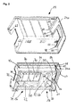
- Fig. 1
- zeigt in schematischer perspektivischer Explosionsdarstellung eine Ausführungsform eines Gehäuses für eine Pipettiervorrichtung.
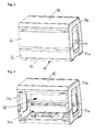
- Fig. 2
- in schematischer Perspektivdarstellung einen oberen Gehäuseteil und einen unteren Gehäuseteil, die jeweils so dargestellt sind, dass der Blick in das Innere des jeweiligen Gehäuseteils ermöglicht ist.
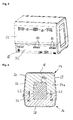
- Fig. 3
- zeigt das Gehäuse der
Fig. 1 im zusammengesetzten Zustand mit geschlossenen Türelementen an der Vorderseite. - Fig. 4
- zeigt das Gehäuse der
Fig. 3 ohne Türelemente. - Fig. 5
- zeigt die Rückseite des Gehäuses der
Fig. 3 . - Fig. 6
- zeigt einen Schnitt durch die Seite des Gehäuses der
Fig. 3 entsprechend der Schnittlinie VI-VI. - Fig. 7
- zeigt eine Pipettiervorrichtung mit selbsttragender Struktur ohne umgebendes Gehäuse.
- Fig. 8
- zeigt die Pipettiervorrichtung der
Fig. 7 aufgenommen in einem unteren Gehäuseteils des Gehäuses. - Fig. 9
- zeigt die im zusammengesetzten Gehäuse der
Fig. 3 aufgenommene Pipettiervorrichtung bei geöffneten Türelementen des Gehäuses. - Fig. 10
- zeigt einen Schnitt durch das Gehäuse der
Fig. 9 in einem mittleren Bereich entsprechend der Schnittlinie X-X derFig. 9 , wobei von der Pipettiervorrichtung aus Gründen der Übersichtlichkeit nur eine Aufnahmeplatte und eine Trägerkonstruktion dargestellt sind und wobei die Türelemente geschlossen sind.
- Fig. 1
- shows a schematic perspective exploded view of an embodiment of a housing for a pipetting device.
- Fig. 2
- in a schematic perspective view of an upper housing part and a lower housing part, which are each shown so that the view is made possible in the interior of the respective housing part.
- Fig. 3
- shows the case of the
Fig. 1 in the assembled state with closed door elements on the front. - Fig. 4
- shows the case of the
Fig. 3 without door elements. - Fig. 5
- shows the back of the case of the
Fig. 3 , - Fig. 6
- shows a section through the side of the housing of
Fig. 3 according to section line VI-VI. - Fig. 7
- shows a pipetting device with self-supporting structure without surrounding housing.
- Fig. 8
- shows the pipetting of the
Fig. 7 received in a lower housing part of the housing. - Fig. 9
- shows the in the assembled housing the
Fig. 3 recorded pipetting with open door elements of the housing. - Fig. 10
- shows a section through the housing of
Fig. 9 in a middle area corresponding to the section line XX ofFig. 9 in which, for reasons of clarity, only one receiving plate and one carrier structure are illustrated by the pipetting device, and wherein the door elements are closed.
In
Der obere Gehäuseteil 14 umfasst ein Gehäusedach 18, eine obere Vorderseite 20, eine hier nicht sichtbare obere Rückseite 22 und zwei obere Seitenwände 24a und 24b, welche die obere Vorderseite 20 und die obere Rückseite 22 miteinander verbinden.The
Der untere Gehäuseteil 16 umfasst einen Gehäuseboden 28, eine untere Vorderseite 30, eine hier nicht sichtbare untere Rückseite 32 und zwei untere Seitenwände 34a und 34b, welche die untere Vorderseite 30 und die untere Rückseite 32 miteinander verbinden.The
Am oberen Gehäuseteil 14, insbesondere an dessen Vorderseite 20 ist ein oberes Türelement 26 angebracht, das mittels Scharnieren 27 um eine obere Schwenkachse OS zwischen einer geschlossenen und einer geöffneten Stellung verschenkbar ist. In der
Am unteren Gehäuseteil 16, insbesondere an dessen Vorderseite 30 ist ein unteres Türelement 36 angebracht, das durch Scharniermittel 37 um eine untere Schwenkachse US zwischen einer geschlossenen und einer geöffneten Stellung verschwenkbar ist. In der
Der obere Gehäuseteil 14 weist in seinen Seitenwänden 24a und 24b jeweilige Aussparungen bzw. Ausschnitte 40a und 40b auf, wobei in der
Wie aus der Explosionsdarstellung der
Die obere Seitenwand 24a weist eine dem unteren Gehäuseteil 16, insbesondere der unteren Seitenwand 34a zugewandte Stirnseite 48 auf, die mehrere Auflageabschnitte 50, 51, 52, 53 umfasst (
Die untere Seitenwand 34a weist korrespondierend eine dem oberen Gehäuseteil 14 zugwandte untere Stirnseite 54 auf, die mehrere Auflageabschnitte 55, 56, 57, 58 umfasst (
Um den oberen Gehäuseteil 14 zusätzlich zu sichern, sind in der unteren Stirnseite 54 beispielhaft zwei Bohrungen 60 vorgesehen, die mit korrespondierenden stift- oder zapfenartigen Verbindungselementen 62 in Eingriff gebracht werden können bzw. in Eingriff stehen, wobei diese Verbindungselemente 62 auch mit dem oberen Gehäuseteil 14 verbunden sind (
Im Bereich dieser Verbindungselemente 62 weist der obere Gehäuseteil 14 auf der Innenseite der Seitenwände 24a, 24b Öffnungen 63 auf, die insbesondere in
An einer Stirnseite der Vorderseite 20 des oberen Gehäuseteils 14 ist eine Aussparung 64 ersichtlich (
Insgesamt können also am oberen Gehäuseteil 14 und am unteren Gehäuseteil 16 mehrere korrespondierende Ausnehmungen und Vorsprünge vorgesehen sein, die eine formschlüssige Verbindung zwischen den beiden Gehäuseteilen 14, 16 ermöglichen und ein sicheres, insbesondere nicht verschiebbares Aufliegen des oberen Gehäuseteils 14 auf dem unteren Gehäuseteil 16 gewährleisten.Overall, therefore, a plurality of corresponding recesses and projections may be provided on the
Wie aus den Darstellungen der
Der Gehäuseboden 28 weist in einem hinteren Bereich, der sich an die untere Rückseite 32 anschließt einen stufenartigen geformten Stützbereich 76 auf. Dieser Stützbereich dient ebenfalls der Abstützung der Pipettiervorrichtung 12, was nachfolgend noch genauer beschrieben wird.The
Die
Die
In diesem Zusammenhang wird noch darauf hingewiesen, dass in den Vertiefungen 72 (
Eine in dem Gehäuse der
An der Positioniervorrichtung 86 sind mehrere Pipettiereinheiten 94 mit einem jeweiligen Pipettierkanal 96 zum Aspirieren und Dispensieren von Probenflüssigkeit aus Probenbehältern angebracht, wobei jeder Pipettierkanal 96 in die drei zueinander orthogonalen Hauptrichtungen (X, Y, Z) beweglich ist mittels hier nicht im Detail beschriebener Antriebseinheiten für die Bewegung entlang der Hauptrichtungen (X, Y Z).Positioned on the
In der Aufnahmeplatte 84 ist auch eine Ausnehmung 98 enthalten, in die beispielsweise eine externe Apparatur, wie etwa ein Thermocycler oder ähnliches aufgenommen werden kann.Also included in the receiving
Aus der Schnittdarstellung der
Das Gehäuse 10, insbesondere dessen beiden Gehäuseteile 14, 16 sind vorzugsweise aus einem Kunststoff, insbesondere einem geschäumten Kunststoff hergestellt. Besonders bevorzugt ist die Herstellung des Gehäuses 10 aus einem Polyurethanschaum. Die Türelemente 26, 36 und die Seitenwandelemente 44a, 44b (
Wie sich aus der vorhergehenden Beschreibung einer Pipettiervorrichtung 12 mit Gehäuse 10 erkennen lässt, können das Gehäuse 10 und die Pipettiervorrichtung 12 unabhängig voneinander hergestellt werden, da insbesondere auf bisher übliche konstruktive Verbindungen zwischen der Tragkonstruktion für die Pipettiervorrichtung und und dem Gehäuse verzichtet wird. In gewisser Weise kann davon gesprochen werden, dass eine Pipettiervorrichtung als Pipettiermodul in ein modularen Gehäuse aufgenommen werden kann. Durch den im Wesentlichen zweiteiligen Aufbau des Gehäuses 10 mit oberem und unterem Gehäuseteil 14, 16 können auch Wartungsarbeiten einfacher durchgeführt werden und es ist ebenfalls möglich eine Pipettiervorrichtung insgesamt auszutauschen, ohne dass auch das Gehäuse oder Gehäusekomponenten getauscht werden müssen.As can be seen from the foregoing description of a
Claims (14)
eine Aufnahmeplatte (84) zur Aufnahme von wenigstens einem Probenbehälter;
wenigstens eine Pipettiereinheit (94) mit einem Pipettierkanal (96) zum Aspirieren und Dispensieren von Probenflüssigkeit aus dem wenigstens einen Probenbehälter, wobei der Pipettierkanal (96) in drei zueinander orthogonalen Hauptrichtungen (X, Y, Z) beweglich ist mittels Antriebseinheiten für die Bewegung entlang der Hauptrichtungen (X, Y Z),
wobei eine mit der Aufnahmeplatte (94) verbundene Trägerkonstruktion (90, 92, 100), an der die Pipettiereinheit (94) gelagert ist und entlang der die Pipettiereinheit (94) in einer der Hauptrichtungen (X) beweglich ist, selbsttragend ausgebildet ist, so dass ein Betrieb der Pipettiervorrichtung (12) unabhängig davon möglich ist, ob die Pipettiervorrichtung in einem Gehäuse aufgenommen ist oder/und verbunden ist.A pipetting device according to any one of the preceding claims, further comprising
a receiving plate (84) for receiving at least one sample container;
at least one pipetting unit (94) having a pipetting channel (96) for aspirating and dispensing sample liquid from the at least one sample container, the pipetting channel (96) being movable in three mutually orthogonal main directions (X, Y, Z) by means of drive units for movement along the main directions (X, YZ),
wherein a carrier structure (90, 92, 100) connected to the receiving plate (94), on which the pipetting unit (94) is mounted and along which the pipetting unit (94) is movable in one of the main directions (X), is designed to be self-supporting an operation of the pipetting device (12) is possible irrespective of whether the pipetting device is accommodated in a housing or / and is connected.
Applications Claiming Priority (1)
| Application Number | Priority Date | Filing Date | Title |
|---|---|---|---|
| DE102014108689.9A DE102014108689A1 (en) | 2014-06-20 | 2014-06-20 | Pipetting device with housing |
Publications (2)
| Publication Number | Publication Date |
|---|---|
| EP2957917A1 true EP2957917A1 (en) | 2015-12-23 |
| EP2957917B1 EP2957917B1 (en) | 2021-04-14 |
Family
ID=53442583
Family Applications (1)
| Application Number | Title | Priority Date | Filing Date |
|---|---|---|---|
| EP15172457.2A Active EP2957917B1 (en) | 2014-06-20 | 2015-06-17 | Pipetting device with housing |
Country Status (3)
| Country | Link |
|---|---|
| EP (1) | EP2957917B1 (en) |
| CN (1) | CN105319377B (en) |
| DE (1) | DE102014108689A1 (en) |
Cited By (1)
| Publication number | Priority date | Publication date | Assignee | Title |
|---|---|---|---|---|
| WO2021121749A1 (en) | 2019-12-18 | 2021-06-24 | Hamilton Bonaduz Ag | Laboratory system |
Families Citing this family (1)
| Publication number | Priority date | Publication date | Assignee | Title |
|---|---|---|---|---|
| CN106967584A (en) * | 2017-05-04 | 2017-07-21 | 南昌大学 | A kind of automated cell suspension blows and beats evenly mixing device |
Citations (4)
| Publication number | Priority date | Publication date | Assignee | Title |
|---|---|---|---|---|
| US5627522A (en) * | 1992-03-27 | 1997-05-06 | Abbott Laboratories | Automated liquid level sensing system |
| EP0895088A2 (en) * | 1997-08-01 | 1999-02-03 | Ortho-Clinical Diagnostics, Inc. | An automated blood analysis system |
| US20090117004A1 (en) * | 2007-11-06 | 2009-05-07 | Abbott Laboratories | System for automatically loading immunoassay analyzer |
| US20120100047A1 (en) * | 2010-07-23 | 2012-04-26 | Matrix Technologies Corporation | Automated liquid handling device |
Family Cites Families (5)
| Publication number | Priority date | Publication date | Assignee | Title |
|---|---|---|---|---|
| DE10020771A1 (en) * | 2000-04-28 | 2001-10-31 | Merck Patent Gmbh | Pipetting device |
| AU2007282135C1 (en) * | 2006-01-18 | 2012-05-24 | Coimmune, Inc. | Systems and methods for processing samples in a closed container, and related devices |
| US8703492B2 (en) * | 2007-04-06 | 2014-04-22 | Qiagen Gaithersburg, Inc. | Open platform hybrid manual-automated sample processing system |
| DE102008022835B3 (en) * | 2008-05-12 | 2009-10-22 | Torsten Dr. Matthias | analyzer |
| US10022856B2 (en) * | 2010-01-28 | 2018-07-17 | The Stanley Works Israel Ltd. | Metal and plastic container |
-
2014
- 2014-06-20 DE DE102014108689.9A patent/DE102014108689A1/en not_active Withdrawn
-
2015
- 2015-06-17 EP EP15172457.2A patent/EP2957917B1/en active Active
- 2015-06-23 CN CN201510349383.8A patent/CN105319377B/en active Active
Patent Citations (4)
| Publication number | Priority date | Publication date | Assignee | Title |
|---|---|---|---|---|
| US5627522A (en) * | 1992-03-27 | 1997-05-06 | Abbott Laboratories | Automated liquid level sensing system |
| EP0895088A2 (en) * | 1997-08-01 | 1999-02-03 | Ortho-Clinical Diagnostics, Inc. | An automated blood analysis system |
| US20090117004A1 (en) * | 2007-11-06 | 2009-05-07 | Abbott Laboratories | System for automatically loading immunoassay analyzer |
| US20120100047A1 (en) * | 2010-07-23 | 2012-04-26 | Matrix Technologies Corporation | Automated liquid handling device |
Non-Patent Citations (1)
| Title |
|---|
| G. ALEXANDER GROSS ET AL: "Robotic alliance of miniaturized synthesis and screening: A case study for the identification of histone deacetylase inhibitors", ENGINEERING IN LIFE SCIENCES, vol. 13, no. 4, 28 July 2013 (2013-07-28), pages 344 - 351, XP055217323, ISSN: 1618-0240, DOI: 10.1002/elsc.201200090 * |
Cited By (2)
| Publication number | Priority date | Publication date | Assignee | Title |
|---|---|---|---|---|
| WO2021121749A1 (en) | 2019-12-18 | 2021-06-24 | Hamilton Bonaduz Ag | Laboratory system |
| DE102019134846B4 (en) | 2019-12-18 | 2023-08-17 | Hamilton Bonaduz Ag | laboratory system |
Also Published As
| Publication number | Publication date |
|---|---|
| EP2957917B1 (en) | 2021-04-14 |
| DE102014108689A1 (en) | 2015-12-24 |
| CN105319377A (en) | 2016-02-10 |
| CN105319377B (en) | 2018-01-16 |
Similar Documents
| Publication | Publication Date | Title |
|---|---|---|
| EP1053581B1 (en) | Control cabinet with cooling device | |
| EP1743128B1 (en) | Domestic appliance having a swiveled display screen | |
| WO2005081091A2 (en) | Assembly of devices | |
| DE2736393A1 (en) | ADJUSTABLE PIN BEARING FOR PIVOT WINDOW | |
| DE102015114702A1 (en) | holding frame | |
| DE102014107168A1 (en) | Frame for electronics or network cabinets | |
| DE10302809A1 (en) | Laboratory incubation cabinet has internal sample tray holder coupled to a surrounding frame by individual agitation mechanism linked to external control system | |
| WO2006133749A1 (en) | Thermocycler | |
| EP2957917B1 (en) | Pipetting device with housing | |
| DE10057556A1 (en) | Tripod head for medical surveillance and treatment systems with carrier profile and apparatus carriage | |
| EP0151478A2 (en) | Enclosure for electrical components | |
| DE19817163C1 (en) | Secure side panel mountings in a switch cabinet for easy removal of side panels by sliding them upwards allow removal of side panels only by opening a secure lid removed by maintenance personnel. | |
| WO2003069746A1 (en) | Frame profile section | |
| AT16188U1 (en) | Heating device with a holding device for receiving a control unit | |
| EP2941480A1 (en) | Incubator | |
| DE2801852A1 (en) | INSTALLATION MEANS FOR THE ARRANGEMENT OF A TV CAMERA FOR THE VIDEO INTERCHANGE IN A TABLEAU FOR AN ELECTRICAL DOOR OPENER | |
| DE102017109437B4 (en) | Vehicle luggage rack mounting kit and assembly method | |
| DE102009055277B4 (en) | Cabel Canal | |
| DE10104215A1 (en) | Pivoting e.g. door module to control cabinet, inserts hinge modules into profile section of door and clips them into engagement with complementary cabinet hinge sections | |
| EP0262427A2 (en) | Table housing for electrotechnical devices | |
| DE7816003U1 (en) | Holding device for threaded nuts | |
| DE4200315C1 (en) | Socket holder for frame or switch cabinet - has transverse carrier joining two supports in parallel of U=shaped profile | |
| DE102017200304B4 (en) | Insulated container | |
| EP1457629A1 (en) | Device for fixing and/or rotatably connecting of door and/or wall members | |
| DE19811713A1 (en) | Pivot mounted switchgear cabinet for e.g. assembly of the walls to the cabinet framework |
Legal Events
| Date | Code | Title | Description |
|---|---|---|---|
| PUAI | Public reference made under article 153(3) epc to a published international application that has entered the european phase |
Free format text: ORIGINAL CODE: 0009012 |
|
| AK | Designated contracting states |
Kind code of ref document: A1 Designated state(s): AL AT BE BG CH CY CZ DE DK EE ES FI FR GB GR HR HU IE IS IT LI LT LU LV MC MK MT NL NO PL PT RO RS SE SI SK SM TR |
|
| AX | Request for extension of the european patent |
Extension state: BA ME |
|
| 17P | Request for examination filed |
Effective date: 20160623 |
|
| RBV | Designated contracting states (corrected) |
Designated state(s): AL AT BE BG CH CY CZ DE DK EE ES FI FR GB GR HR HU IE IS IT LI LT LU LV MC MK MT NL NO PL PT RO RS SE SI SK SM TR |
|
| GRAP | Despatch of communication of intention to grant a patent |
Free format text: ORIGINAL CODE: EPIDOSNIGR1 |
|
| STAA | Information on the status of an ep patent application or granted ep patent |
Free format text: STATUS: GRANT OF PATENT IS INTENDED |
|
| INTG | Intention to grant announced |
Effective date: 20201106 |
|
| GRAS | Grant fee paid |
Free format text: ORIGINAL CODE: EPIDOSNIGR3 |
|
| GRAA | (expected) grant |
Free format text: ORIGINAL CODE: 0009210 |
|
| STAA | Information on the status of an ep patent application or granted ep patent |
Free format text: STATUS: THE PATENT HAS BEEN GRANTED |
|
| AK | Designated contracting states |
Kind code of ref document: B1 Designated state(s): AL AT BE BG CH CY CZ DE DK EE ES FI FR GB GR HR HU IE IS IT LI LT LU LV MC MK MT NL NO PL PT RO RS SE SI SK SM TR |
|
| REG | Reference to a national code |
Ref country code: GB Ref legal event code: FG4D Free format text: NOT ENGLISH |
|
| REG | Reference to a national code |
Ref country code: CH Ref legal event code: EP |
|
| REG | Reference to a national code |
Ref country code: DE Ref legal event code: R096 Ref document number: 502015014544 Country of ref document: DE |
|
| REG | Reference to a national code |
Ref country code: IE Ref legal event code: FG4D Free format text: LANGUAGE OF EP DOCUMENT: GERMAN |
|
| REG | Reference to a national code |
Ref country code: AT Ref legal event code: REF Ref document number: 1382883 Country of ref document: AT Kind code of ref document: T Effective date: 20210515 |
|
| REG | Reference to a national code |
Ref country code: LT Ref legal event code: MG9D |
|
| REG | Reference to a national code |
Ref country code: NL Ref legal event code: MP Effective date: 20210414 |
|
| PG25 | Lapsed in a contracting state [announced via postgrant information from national office to epo] |
Ref country code: HR Free format text: LAPSE BECAUSE OF FAILURE TO SUBMIT A TRANSLATION OF THE DESCRIPTION OR TO PAY THE FEE WITHIN THE PRESCRIBED TIME-LIMIT Effective date: 20210414 Ref country code: FI Free format text: LAPSE BECAUSE OF FAILURE TO SUBMIT A TRANSLATION OF THE DESCRIPTION OR TO PAY THE FEE WITHIN THE PRESCRIBED TIME-LIMIT Effective date: 20210414 Ref country code: NL Free format text: LAPSE BECAUSE OF FAILURE TO SUBMIT A TRANSLATION OF THE DESCRIPTION OR TO PAY THE FEE WITHIN THE PRESCRIBED TIME-LIMIT Effective date: 20210414 Ref country code: LT Free format text: LAPSE BECAUSE OF FAILURE TO SUBMIT A TRANSLATION OF THE DESCRIPTION OR TO PAY THE FEE WITHIN THE PRESCRIBED TIME-LIMIT Effective date: 20210414 Ref country code: BG Free format text: LAPSE BECAUSE OF FAILURE TO SUBMIT A TRANSLATION OF THE DESCRIPTION OR TO PAY THE FEE WITHIN THE PRESCRIBED TIME-LIMIT Effective date: 20210714 |
|
| PG25 | Lapsed in a contracting state [announced via postgrant information from national office to epo] |
Ref country code: GR Free format text: LAPSE BECAUSE OF FAILURE TO SUBMIT A TRANSLATION OF THE DESCRIPTION OR TO PAY THE FEE WITHIN THE PRESCRIBED TIME-LIMIT Effective date: 20210715 Ref country code: LV Free format text: LAPSE BECAUSE OF FAILURE TO SUBMIT A TRANSLATION OF THE DESCRIPTION OR TO PAY THE FEE WITHIN THE PRESCRIBED TIME-LIMIT Effective date: 20210414 Ref country code: IS Free format text: LAPSE BECAUSE OF FAILURE TO SUBMIT A TRANSLATION OF THE DESCRIPTION OR TO PAY THE FEE WITHIN THE PRESCRIBED TIME-LIMIT Effective date: 20210814 Ref country code: NO Free format text: LAPSE BECAUSE OF FAILURE TO SUBMIT A TRANSLATION OF THE DESCRIPTION OR TO PAY THE FEE WITHIN THE PRESCRIBED TIME-LIMIT Effective date: 20210714 Ref country code: PL Free format text: LAPSE BECAUSE OF FAILURE TO SUBMIT A TRANSLATION OF THE DESCRIPTION OR TO PAY THE FEE WITHIN THE PRESCRIBED TIME-LIMIT Effective date: 20210414 Ref country code: PT Free format text: LAPSE BECAUSE OF FAILURE TO SUBMIT A TRANSLATION OF THE DESCRIPTION OR TO PAY THE FEE WITHIN THE PRESCRIBED TIME-LIMIT Effective date: 20210816 Ref country code: ES Free format text: LAPSE BECAUSE OF FAILURE TO SUBMIT A TRANSLATION OF THE DESCRIPTION OR TO PAY THE FEE WITHIN THE PRESCRIBED TIME-LIMIT Effective date: 20210414 Ref country code: SE Free format text: LAPSE BECAUSE OF FAILURE TO SUBMIT A TRANSLATION OF THE DESCRIPTION OR TO PAY THE FEE WITHIN THE PRESCRIBED TIME-LIMIT Effective date: 20210414 Ref country code: RS Free format text: LAPSE BECAUSE OF FAILURE TO SUBMIT A TRANSLATION OF THE DESCRIPTION OR TO PAY THE FEE WITHIN THE PRESCRIBED TIME-LIMIT Effective date: 20210414 |
|
| REG | Reference to a national code |
Ref country code: DE Ref legal event code: R097 Ref document number: 502015014544 Country of ref document: DE |
|
| PG25 | Lapsed in a contracting state [announced via postgrant information from national office to epo] |
Ref country code: SM Free format text: LAPSE BECAUSE OF FAILURE TO SUBMIT A TRANSLATION OF THE DESCRIPTION OR TO PAY THE FEE WITHIN THE PRESCRIBED TIME-LIMIT Effective date: 20210414 Ref country code: SK Free format text: LAPSE BECAUSE OF FAILURE TO SUBMIT A TRANSLATION OF THE DESCRIPTION OR TO PAY THE FEE WITHIN THE PRESCRIBED TIME-LIMIT Effective date: 20210414 Ref country code: CZ Free format text: LAPSE BECAUSE OF FAILURE TO SUBMIT A TRANSLATION OF THE DESCRIPTION OR TO PAY THE FEE WITHIN THE PRESCRIBED TIME-LIMIT Effective date: 20210414 Ref country code: EE Free format text: LAPSE BECAUSE OF FAILURE TO SUBMIT A TRANSLATION OF THE DESCRIPTION OR TO PAY THE FEE WITHIN THE PRESCRIBED TIME-LIMIT Effective date: 20210414 Ref country code: DK Free format text: LAPSE BECAUSE OF FAILURE TO SUBMIT A TRANSLATION OF THE DESCRIPTION OR TO PAY THE FEE WITHIN THE PRESCRIBED TIME-LIMIT Effective date: 20210414 Ref country code: RO Free format text: LAPSE BECAUSE OF FAILURE TO SUBMIT A TRANSLATION OF THE DESCRIPTION OR TO PAY THE FEE WITHIN THE PRESCRIBED TIME-LIMIT Effective date: 20210414 Ref country code: MC Free format text: LAPSE BECAUSE OF FAILURE TO SUBMIT A TRANSLATION OF THE DESCRIPTION OR TO PAY THE FEE WITHIN THE PRESCRIBED TIME-LIMIT Effective date: 20210414 |
|
| PLBE | No opposition filed within time limit |
Free format text: ORIGINAL CODE: 0009261 |
|
| STAA | Information on the status of an ep patent application or granted ep patent |
Free format text: STATUS: NO OPPOSITION FILED WITHIN TIME LIMIT |
|
| REG | Reference to a national code |
Ref country code: BE Ref legal event code: MM Effective date: 20210630 |
|
| 26N | No opposition filed |
Effective date: 20220117 |
|
| GBPC | Gb: european patent ceased through non-payment of renewal fee |
Effective date: 20210714 |
|
| PG25 | Lapsed in a contracting state [announced via postgrant information from national office to epo] |
Ref country code: LU Free format text: LAPSE BECAUSE OF NON-PAYMENT OF DUE FEES Effective date: 20210617 |
|
| PG25 | Lapsed in a contracting state [announced via postgrant information from national office to epo] |
Ref country code: IE Free format text: LAPSE BECAUSE OF NON-PAYMENT OF DUE FEES Effective date: 20210617 Ref country code: GB Free format text: LAPSE BECAUSE OF NON-PAYMENT OF DUE FEES Effective date: 20210714 |
|
| PG25 | Lapsed in a contracting state [announced via postgrant information from national office to epo] |
Ref country code: IS Free format text: LAPSE BECAUSE OF FAILURE TO SUBMIT A TRANSLATION OF THE DESCRIPTION OR TO PAY THE FEE WITHIN THE PRESCRIBED TIME-LIMIT Effective date: 20210814 Ref country code: FR Free format text: LAPSE BECAUSE OF NON-PAYMENT OF DUE FEES Effective date: 20210630 Ref country code: AL Free format text: LAPSE BECAUSE OF FAILURE TO SUBMIT A TRANSLATION OF THE DESCRIPTION OR TO PAY THE FEE WITHIN THE PRESCRIBED TIME-LIMIT Effective date: 20210414 |
|
| PG25 | Lapsed in a contracting state [announced via postgrant information from national office to epo] |
Ref country code: IT Free format text: LAPSE BECAUSE OF FAILURE TO SUBMIT A TRANSLATION OF THE DESCRIPTION OR TO PAY THE FEE WITHIN THE PRESCRIBED TIME-LIMIT Effective date: 20210414 Ref country code: BE Free format text: LAPSE BECAUSE OF NON-PAYMENT OF DUE FEES Effective date: 20210630 |
|
| REG | Reference to a national code |
Ref country code: AT Ref legal event code: MM01 Ref document number: 1382883 Country of ref document: AT Kind code of ref document: T Effective date: 20210617 |
|
| PG25 | Lapsed in a contracting state [announced via postgrant information from national office to epo] |
Ref country code: AT Free format text: LAPSE BECAUSE OF NON-PAYMENT OF DUE FEES Effective date: 20210617 |
|
| PG25 | Lapsed in a contracting state [announced via postgrant information from national office to epo] |
Ref country code: HU Free format text: LAPSE BECAUSE OF FAILURE TO SUBMIT A TRANSLATION OF THE DESCRIPTION OR TO PAY THE FEE WITHIN THE PRESCRIBED TIME-LIMIT; INVALID AB INITIO Effective date: 20150617 |
|
| P01 | Opt-out of the competence of the unified patent court (upc) registered |
Effective date: 20230521 |
|
| PG25 | Lapsed in a contracting state [announced via postgrant information from national office to epo] |
Ref country code: CY Free format text: LAPSE BECAUSE OF FAILURE TO SUBMIT A TRANSLATION OF THE DESCRIPTION OR TO PAY THE FEE WITHIN THE PRESCRIBED TIME-LIMIT Effective date: 20210414 |
|
| PGFP | Annual fee paid to national office [announced via postgrant information from national office to epo] |
Ref country code: DE Payment date: 20230523 Year of fee payment: 9 |
|
| PGFP | Annual fee paid to national office [announced via postgrant information from national office to epo] |
Ref country code: CH Payment date: 20230702 Year of fee payment: 9 |