EP2913153A1 - Lifting device - Google Patents
Lifting device Download PDFInfo
- Publication number
- EP2913153A1 EP2913153A1 EP15159529.5A EP15159529A EP2913153A1 EP 2913153 A1 EP2913153 A1 EP 2913153A1 EP 15159529 A EP15159529 A EP 15159529A EP 2913153 A1 EP2913153 A1 EP 2913153A1
- Authority
- EP
- European Patent Office
- Prior art keywords
- suction mount
- lifting arm
- lifting
- suction
- devices
- Prior art date
- Legal status (The legal status is an assumption and is not a legal conclusion. Google has not performed a legal analysis and makes no representation as to the accuracy of the status listed.)
- Granted
Links
Images


Classifications
-
- B—PERFORMING OPERATIONS; TRANSPORTING
- B65—CONVEYING; PACKING; STORING; HANDLING THIN OR FILAMENTARY MATERIAL
- B65G—TRANSPORT OR STORAGE DEVICES, e.g. CONVEYORS FOR LOADING OR TIPPING, SHOP CONVEYOR SYSTEMS OR PNEUMATIC TUBE CONVEYORS
- B65G7/00—Devices for assisting manual moving or tilting heavy loads
- B65G7/12—Load carriers, e.g. hooks, slings, harness, gloves, modified for load carrying
-
- B—PERFORMING OPERATIONS; TRANSPORTING
- B25—HAND TOOLS; PORTABLE POWER-DRIVEN TOOLS; MANIPULATORS
- B25B—TOOLS OR BENCH DEVICES NOT OTHERWISE PROVIDED FOR, FOR FASTENING, CONNECTING, DISENGAGING OR HOLDING
- B25B11/00—Work holders not covered by any preceding group in the subclass, e.g. magnetic work holders, vacuum work holders
- B25B11/005—Vacuum work holders
- B25B11/007—Vacuum work holders portable, e.g. handheld
-
- B—PERFORMING OPERATIONS; TRANSPORTING
- B65—CONVEYING; PACKING; STORING; HANDLING THIN OR FILAMENTARY MATERIAL
- B65G—TRANSPORT OR STORAGE DEVICES, e.g. CONVEYORS FOR LOADING OR TIPPING, SHOP CONVEYOR SYSTEMS OR PNEUMATIC TUBE CONVEYORS
- B65G49/00—Conveying systems characterised by their application for specified purposes not otherwise provided for
- B65G49/05—Conveying systems characterised by their application for specified purposes not otherwise provided for for fragile or damageable materials or articles
- B65G49/06—Conveying systems characterised by their application for specified purposes not otherwise provided for for fragile or damageable materials or articles for fragile sheets, e.g. glass
- B65G49/061—Lifting, gripping, or carrying means, for one or more sheets forming independent means of transport, e.g. suction cups, transport frames
-
- B—PERFORMING OPERATIONS; TRANSPORTING
- B65—CONVEYING; PACKING; STORING; HANDLING THIN OR FILAMENTARY MATERIAL
- B65G—TRANSPORT OR STORAGE DEVICES, e.g. CONVEYORS FOR LOADING OR TIPPING, SHOP CONVEYOR SYSTEMS OR PNEUMATIC TUBE CONVEYORS
- B65G2249/00—Aspects relating to conveying systems for the manufacture of fragile sheets
- B65G2249/04—Arrangements of vacuum systems or suction cups
Abstract
Description
- The present invention relates to a lifting device, and in particular to such a device for use in lifting sheets or panels, more particularly for lifting glazing panels.
- Lifting devices including a suction mount arrangement enabling securing of the lifting device to a body to be lifted (for example a glazing panel) are known. Exemplary such lifting devices are disclosed for example in
DE2013755 and infigure 5 ofWO2007/039738 . Devices include spaced sucker suction devices mounted to an interconnecting handle. Such devices are often referred to as 'telephone sucker' or 'telephone lifter' devices in view of their appearance resembling a telephone handset. Typically the suction devices include a lever having a cam which is movable to urge a cam follower to push down the concave dish of the flexible sucker body so energising or de-energising the suction device. The interconnecting handle provides a grip for the device to enable lifting of the relevant windscreen or the like. - Recently lifting and positioning assistance devices such as that disclosed in
US7216411 have come into use, particularly for large glazing panels to be installed in vehicles. The device also includes a suction mount arrangement to secure a support tube 36 to the glazing panel. When using lifting assistance devices in concert with using traditional telephone sucker type lifting devices, it is difficult to maintain comfortable hand wrist and arm positions. - An improved and more versatile lifting device has now been developed.
- According to the present invention, there is provided a lifting device comprising an elongate lifting arm having a suction mount arrangement enabling securing of the device to a body to be lifted, the suction mount arrangement comprising first and second suction devices spaced apart in the longitudinal direction of the lifting arm wherein the spacing between the first and second suction mount devices is sufficient for a user to grip the lifting arm in between the first and second suction mount devices; the device extending away from the suction mount arrangement, in the longitudinal direction of the lifting arm, to a handle portion spaced from the suction mount arrangement in the longitudinal direction, and extending upwardly above the lifting arm on the opposite side of the lifting arm to the suction mount devices.
- It is preferred that the lifting arm portion extends away from the suction mount arrangement by a distance equal to or more than the spacing between the first and second suction mount devices. This provides a good length of lifting arm to enable versatile lifting practices to be utilised.
- Beneficially, the spacing between the first and second suction mount devices is sufficient for a user to grip the device in between the first and second suction mount devices. Particularly, it is desirable that the spacing between the position of fixing the suction mounting devices to the lifting device is sufficient for a user to grip the device in between fixing positions.
- It is preferred that the suction mount arrangement is mounted to the device by means of an adjustable and/or flexible fixing arrangement. In one embodiment this may be achieved by means of providing a tilting/pivoting fixing which enables the suction mount to be pivoted or tilted with respect to the elongate lifting arm.
- In a preferred embodiment, the handle portion has a plurality of handle grip portions extending in different attitudes, angles or in different orientations. In such an embodiment a first handle portion preferably extends in a generally upward orientation and a second handle portion may preferably extend in a direction generally outwardly from the mounting portion of the device. Beneficially an angled, curve-form or bowed grip portion interconnects the first and second handle to form a closed handle ring. The arrangement provides a handle grip above the level of the mounting arm, in addition to the grip between the mounting suction devices. Such features provide ergonomic benefits and possibility of variety of potential use.
- Beneficially, the suction mount arrangement is mounted with respect to the device to extend downwardly (i.e the suction mount arrangement is under-slung with respect to the lifting arm of the device).
- The invention will now be further described in specific embodiments, by way of example only, and with reference to the accompanying drawings in which;
-
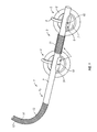
Figure 1 is a perspective view of a first embodiment of lifting device in accordance with the invention; -
Figure 2 is a view of a second embodiment of lifting device in accordance with the invention; -
Figures 3a to 3c are schematic views of the lifting device of the present invention in use in various applications; -
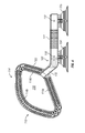
Figure 4 is a side view of an alternative embodiment of lifting device in accordance with the present invention; -
Figure 5 is a plan view of the embodiment offigure 4 . - Referring initially to
Figure 1 , there is shown alifting device 1 comprising an elongatetubular lifting arm 2 which has amounting section 3 to which are mounted a pair of suction mount devices 4,5. The mounting devices may be generally in accordance with known prior art devices such as disclosed for example inDE20103755 andWO2007/039738 and may comprise a flexible rubber sucker 6 mounted to a hardplastic mounting shell 7. Anactuation lever 8 is pivotally mounted to themounting shell 7, the primary purpose of the actuation lever being to energise or de-energise the sucker when the lever is moved between an energised and a de-energised position. The suction mount device 4, 5 can in this way be placed on a surface (such as a glazing panel) and energised to form a reduced pressure suction engagement with the surface. This engagement is robust enough to enable the panel to be lifted with the suction mount device 4,5. - Each of the sucker mount devices 4,5 is mounted to the
mounting section 3 of thelifting arm 2 by means of a pivotally securedmounting bracket 9 secured by apivot pin 10 and permitting pivotal movement over a small range with respect to themounting arm 2. This limited pivotal movement of the sucker mount devices 4,5 is sufficient to ensure good sealing contact on curved glazing panels (such as curved windshields). - The portion of the lifting arm extending between the mounting
pivot pins 10 is provided with aplastics grip sheath 11. Distance between themounting pins 10 is such that the user can easily grip the lifting arm in the mounting section between the suction mount devices 4,5. - Extending away from lifting
arm 2 toward adistal end 12 of the device is acantilever extension section 15 of thelifting arm 2. Typically thecantilever extension section 15 of thelever arm 2 extends away from themounting section 3 by distance of equal or more to the length of the mounting section 3 (typically the extension section length is in the range 20 to 50 cm). Therefore a relatively long extension is provided extending away from themounting section 3. Towards itsdistal end 12 theextension section 15 is provided with a curved-form handle portion 14 which curves upwardly with respect to the mounting section. Thecurved section 14 is provided with aplastics grip sheath 13. The curveform handle section 14 is of sufficient length and curvature to be gripped by a user in a variety of positions. - Referring now to the embodiment of
figure 2 , where like parts are identified with like reference numerals with respect tofigure 1 . The arrangement offigure 2 is generally identical to the arrangement offigure 1 in respect of themounting section 3 and the under slung mounting of the suction mounting devices 4,5. - The
extension section 15 of thelifting arm 2 also extends to an upwardly curveddistal end handle 14. However in this instance, between thedistal end handle 14 and themounting section 3, theextension portion 15 of thelifting handle 2 is curved to a bow-form section 17 extending upwardly with respect to themounting section 3. This bow-section 17 has in certain uses been found to provide ergonomic benefits. Theextension section 15 extends from themounting section 3 for approximately 30cms whereas the distance between themounting pins 10 of the suction mount devices 4,5 is approximately 22cms. A device having these dimensions has been found to be suitable for ergonomic use in practice. - An alternative embodiment of lifting device is shown in
figures 4 and5 . In the embodiment shown, the mounting section of the device is generally similar to the mounting section of the device shown in the previous embodiments. Each of thesucker mount devices mounting section 103 of thelifting arm 102 by means of a pivotally secured mounting bracket secured by apivot pin 110 and permitting pivotal movement over a small range with respect to themounting arm 102. This limited pivotal movement of thesucker mount devices - The portion of the lifting arm extending between the mounting
pivot pins 110 is provided with aplastics grip sheath 111. Distance between thesuction mount devices lifting arm 102 in the mounting section between the suction mount devices 104,105. As can be seen from the plan view infigure 5 , the longitudinal axis of thelifting arm 102 is offset from the axis of thesucker devices lever actuation mechanism 108 of thesucker devices - Extending away from
mounting section 103 toward adistal end 112 of the device is ashort extension section 115 of thelifting arm 102. Theshort extension section 115 is angled to extend upwardly in an upward direction on the opposite side of thelifting arm 102 to thesuction devices short extension 115 connects with ahandle arrangement 114 which includeshandle sections 114a 114b and 114c of differing orientations.Handle section 114a extends outwardly away from the mounting section and is inclined slightly downwardly (to the side of the device on which the suction mount devices are positioned). Handle section 114c extends upwardly away from themounting section 103 and is inclined slightly toward themounting section 103. - Handle section 104b is curved or angled to connect with spaced portions of the handle sections 104a and 104c to form a closed handle ring having a
central opening zone 120. Handle sections 104a and 104c are preferably of a size (length) to be gripped by a hand of the user. Handle section 104b is at least long enough to be gripped by two hands of the user arranged side by side gripping the handle length. The differently orientated and positioned handle sections 104a104b 104c 111 enable a number of different gripping possibilities and provide enhanced versatility of use options. - The distal end of the handle arrangement is spaced from the mounting section by a distance substantially corresponding to (or greater than) the spacing of the
suction mount devices section 103. The handle arrangement projects upwardly above the lifting arm on the opposite side of the lifting arm to the suction mount devices. - The lifting device has been found extremely versatile in terms of its applicability for different uses. As shown in
figure 3a , a user can use a pair of devices gripped in the mountingsection 3 to lift and place a glazing panel such as a windshield in the same manner as telephone sucker devices as known in the prior art have previously been used. In such lifting applications theextension section 15 and upwardly extendinghandle 14 is not used and is directed away from the user. - Additionally, the lifting device of the present invention can be used for glazing panel installations using a lifting assistance device such as for example disclosed in
US7216411 . Such an application is shown infigure 3b in which theassistance device 50 comprises a pivotedarm 51 having asucker mount 52 which is secured by suction to thewindshield 100. The user may use thedevice 1 of the present invention as a pair with one held in each hand and in this instance, because the windshield is relatively large (necessitating the use of the assistance device 50) the user may grip thehandle 114 of the device by the upwardly curved distal end handle section 14b. Thecurved handle portions 114b are positioned such that they extend beyond the periphery of the glazing panel. The installer is then able to find the most comfortable position for their hands on the curved part of the handle. This enables the arms to remain tucked in at the side of the user, which provides the safest and the easiest position for lifting. Having his hands positioned outside the periphery of the glazing panel allows the installer to manoeuvre the glazing panel by pushing from below rather than from pulling from above so that they can more comfortably and safely work on taller vehicles. Also the extension that the device provides by virtue of the extension section and handle 114 extending away from the mounting section 113 provides more convenient and safer means for movement of the glazing panels around higher vehicles with longer bonnets. - The device of the present invention may also be used for two person installations as shown in
figure 3c , particularly for large glazing panels. Each installer has one pair of lifting devices which are positioned one towards the top and one towards the bottom of the glazing panel. The distal end handles 114 extend outwardly beyond the periphery of theglazing panel 100. - Each installer is able to find the most comfortable
handle section position 114a 114b 114c on thedistal end handle 114. In this context the provision of the bowedsection 17 of the embodimentfigure 2 has been found to provide benefits. The ability to grip thehandle sections 114b and 114c positioned above the level of thelifting arm 102 sucker mount devices is particularly useful in certain circumstances. - Because the
handle portions 114 are positioned outwardly of the periphery of the glazing panel, the installers can comfortably use both hands and push from below with a neutral wrist position rather than pull from above where the wrist will inevitably become bent which is less favourable from a safety and ergonomic point of view. An additional benefit of being able to use the handle extension is that the user will generally have a better view for positioning the glass allowing careful laying in of both top and bottom edges. - The device provides a useful and versatile lifting tool for use individually, in pairs or in combination with other devices.
Claims (10)
- A lifting device comprising an elongate lifting arm having a suction mount arrangement enabling securing of the device to a body to be lifted, the suction mount arrangement comprising first and second suction devices spaced apart in the longitudinal direction of the lifting arm wherein the spacing between the first and second suction mount devices is sufficient for a user to grip the lifting arm in between the first and second suction mount devices; the device extending away from the suction mount arrangement, in the longitudinal direction of the lifting arm, to a handle portion spaced from the suction mount arrangement in the longitudinal direction, and extending upwardly above the lifting arm on the opposite side of the lifting arm to the suction mount devices.
- A lifting device according to claim 1, wherein the handle portion extends away from the suction mount arrangement by a distance substantially equal to, or more than, the spacing between the first and second suction mount devices.
- A lifting device according to claim 1 or claim 2, wherein the handle portion has a plurality of handle grip portions in different orientations.
- A lifting device according to claim 3, wherein a first handle portion extends in a generally upward orientation and a second handle portion extends in a direction generally outwardly from the mounting portion of the device.
- A lifting device according to claim 4, wherein an angled or bowed grip portion interconnects the first and second handle to form a closed handle ring.
- A lifting device according to any preceding claim, wherein the suction mount arrangement is mounted to the device by means of an adjustable fixing arrangement.
- A lifting device according to claim 6, wherein the adjustable fixing arrangement enables the suction mount to be pivoted or tilted with respect to the elongate lifting arm.
- A lifting device according to any preceding claim, wherein the upwardly extending handle portion is positioned proximate the end of the lifting arm spaced from the suction mount.
- A lifting device according to any preceding claim in which the suction mount arrangement is mounted with respect to the device below the lifting arm.
- A lifting device comprising an elongate lifting arm having a suction mount arrangement enabling securing of the device to a body to be lifted, the suction mount arrangement comprising first and second suction devices spaced apart in the longitudinal direction of the lifting arm wherein the spacing between the first and second suction mount devices is sufficient for a user to grip the lifting arm in between the first and second suction mount devices; the device extending away from the suction mount arrangement, in the longitudinal direction of the lifting arm, to a handle portion spaced from the suction mount arrangement in the longitudinal direction.
Priority Applications (3)
| Application Number | Priority Date | Filing Date | Title |
|---|---|---|---|
| SI201031524T SI2913153T1 (en) | 2009-05-06 | 2010-05-05 | Lifting device |
| PL15159529T PL2913153T3 (en) | 2009-05-06 | 2010-05-05 | Lifting device |
| HRP20171226TT HRP20171226T1 (en) | 2009-05-06 | 2017-08-08 | Lifting device |
Applications Claiming Priority (2)
| Application Number | Priority Date | Filing Date | Title |
|---|---|---|---|
| GB0907781.9A GB2470035B (en) | 2009-05-06 | 2009-05-06 | Suction lifting device for glazing panels with cantilever handle |
| EP10720646.8A EP2427303B1 (en) | 2009-05-06 | 2010-05-05 | Lifting device |
Related Parent Applications (1)
| Application Number | Title | Priority Date | Filing Date |
|---|---|---|---|
| EP10720646.8A Division EP2427303B1 (en) | 2009-05-06 | 2010-05-05 | Lifting device |
Publications (2)
| Publication Number | Publication Date |
|---|---|
| EP2913153A1 true EP2913153A1 (en) | 2015-09-02 |
| EP2913153B1 EP2913153B1 (en) | 2017-05-17 |
Family
ID=40802170
Family Applications (2)
| Application Number | Title | Priority Date | Filing Date |
|---|---|---|---|
| EP10720646.8A Active EP2427303B1 (en) | 2009-05-06 | 2010-05-05 | Lifting device |
| EP15159529.5A Active EP2913153B1 (en) | 2009-05-06 | 2010-05-05 | Lifting device |
Family Applications Before (1)
| Application Number | Title | Priority Date | Filing Date |
|---|---|---|---|
| EP10720646.8A Active EP2427303B1 (en) | 2009-05-06 | 2010-05-05 | Lifting device |
Country Status (25)
| Country | Link |
|---|---|
| US (2) | US8444193B2 (en) |
| EP (2) | EP2427303B1 (en) |
| CN (1) | CN102421565B (en) |
| AR (1) | AR076853A1 (en) |
| AU (1) | AU2010244274B2 (en) |
| BR (1) | BRPI1013968A8 (en) |
| CA (1) | CA2759858C (en) |
| CL (1) | CL2011002752A1 (en) |
| DK (2) | DK2913153T3 (en) |
| ES (2) | ES2542027T3 (en) |
| GB (1) | GB2470035B (en) |
| HK (1) | HK1144567A1 (en) |
| HR (2) | HRP20150742T1 (en) |
| HU (1) | HUE034964T2 (en) |
| LT (1) | LT2913153T (en) |
| ME (1) | ME01293B (en) |
| MX (1) | MX2011011323A (en) |
| NZ (1) | NZ595816A (en) |
| PL (2) | PL2427303T3 (en) |
| PT (2) | PT2913153T (en) |
| RS (1) | RS54151B1 (en) |
| RU (1) | RU2533959C2 (en) |
| SI (2) | SI2427303T1 (en) |
| TW (1) | TWI450800B (en) |
| WO (1) | WO2010128282A1 (en) |
Cited By (1)
| Publication number | Priority date | Publication date | Assignee | Title |
|---|---|---|---|---|
| DE102018110432B4 (en) * | 2017-05-04 | 2020-11-19 | GM Global Technology Operations LLC | DEVICE FOR INSTALLING A WINDSHIELD ON A MOTOR VEHICLE |
Families Citing this family (12)
| Publication number | Priority date | Publication date | Assignee | Title |
|---|---|---|---|---|
| GB2470035B (en) * | 2009-05-06 | 2013-12-18 | Belron Hungary Kft Zug Branch | Suction lifting device for glazing panels with cantilever handle |
| US9889909B2 (en) * | 2013-07-27 | 2018-02-13 | Dean Morgan | Apparatus and method for wake shaping |
| TWM473385U (en) * | 2013-10-16 | 2014-03-01 | Wistron Corp | Moving fixture and related moving apparatus |
| CN104713951B (en) | 2013-12-13 | 2018-05-22 | 通用电气公司 | It is improved to carry falling unit and use its ultrasonic testing system |
| EP3169204B1 (en) * | 2014-07-18 | 2019-10-09 | PI-Design AG | Kitchen appliance for processing foodstuff |
| US10190345B2 (en) * | 2015-05-21 | 2019-01-29 | Kyle S. McCullough | Suction cup child restraint lock for sliding doors/windows |
| WO2017028278A1 (en) | 2015-08-19 | 2017-02-23 | General Electric Company | Lifting apparatus and ultrasonic inspection system |
| US9687098B1 (en) * | 2016-08-03 | 2017-06-27 | Patrick L. Liles, Sr. | Server tray support |
| CN108032276A (en) * | 2017-12-22 | 2018-05-15 | 安徽机电职业技术学院 | A kind of round steel sheet pickup magnetic force adsorption apparatus |
| US20210236337A1 (en) * | 2020-01-30 | 2021-08-05 | Augmented Vision Labs | Contact lens insertion system |
| USD901267S1 (en) * | 2020-06-11 | 2020-11-10 | Shenzhen Xinqi Chuangwei E-Commerce Co., Ltd. | Hand-operated automotive repair tool |
| US11634929B1 (en) | 2021-01-05 | 2023-04-25 | Francisco Francisco Felipe | System for a hand attached suction cup for the touchless opening of a door |
Citations (3)
| Publication number | Priority date | Publication date | Assignee | Title |
|---|---|---|---|---|
| US5707094A (en) * | 1996-06-12 | 1998-01-13 | Chrysler Corporation | Battery lift apparatus for electric vehicles |
| WO1999012840A1 (en) * | 1997-09-08 | 1999-03-18 | P-Frame Pty. Ltd. | Sheet material lifting implement |
| US20060156533A1 (en) * | 2004-09-23 | 2006-07-20 | Mayhugh Kent R | Single technician large windshield installation tool |
Family Cites Families (45)
| Publication number | Priority date | Publication date | Assignee | Title |
|---|---|---|---|---|
| US1830520A (en) * | 1930-01-10 | 1931-11-03 | Harry E Moyses | Device for picking up golf balls and like articles |
| US2127154A (en) * | 1936-07-09 | 1938-08-16 | Adolph F Lange | Handling implement for plate glass and the like |
| US2131687A (en) * | 1937-07-01 | 1938-09-27 | Kastar Specialty Mfg Co Inc | Suction handle |
| US2212755A (en) * | 1938-11-21 | 1940-08-27 | Harry A Solomon | Handling device |
| US2287576A (en) * | 1938-11-21 | 1942-06-23 | Harry A Solomon | Handling device |
| US2303393A (en) * | 1940-01-10 | 1942-12-01 | Charles O Moore | Vacuum lifting device |
| US2523157A (en) * | 1946-03-19 | 1950-09-19 | Somma Raymond | Vacuum-cup record-transporting device |
| US2871054A (en) * | 1956-07-05 | 1959-01-27 | Zinke Erwin Max | Suction cup |
| US3061351A (en) * | 1959-04-08 | 1962-10-30 | Robert D Johnson | Linoleum puller |
| US3219377A (en) * | 1962-03-28 | 1965-11-23 | Allen Benigene | Vacuum lifter tool |
| FR2071469A5 (en) | 1969-03-24 | 1971-09-17 | Pinlites Inc | |
| US3831991A (en) * | 1973-01-12 | 1974-08-27 | J Lukeman | Apparatus and system for gaining access to conflagrations |
| US3913964A (en) * | 1973-01-12 | 1975-10-21 | John R Lukeman | Apparatus and system for gaining access to conflagrations |
| FR2225964A5 (en) * | 1973-04-11 | 1974-11-08 | Lamothe Pierre | Windscreen installing frame - length adjustable arms carry screw mounted suction cups |
| DE7723048U1 (en) * | 1977-07-23 | 1978-08-10 | Fa. Josef Bohle, 5650 Solingen | GRIPPER WITH SUCTION PAD |
| SU1184785A1 (en) * | 1983-06-07 | 1985-10-15 | Центральный Научно-Исследовательский И Проектно-Экспериментальный Институт Организации,Механизации И Технической Помощи Строительству | Vacuum gripping device |
| US4477113A (en) * | 1983-06-14 | 1984-10-16 | Lybolt Arden F | Wood handling tool |
| US4612661A (en) * | 1984-03-30 | 1986-09-16 | Dallas Donald W | Suction engaging x-ray cassette container |
| JPS6387831U (en) * | 1986-11-26 | 1988-06-08 | ||
| FR2628724B1 (en) * | 1988-03-17 | 1990-08-24 | Adler Sa | SUCTION HANDLE ASSEMBLY |
| JPH02222557A (en) * | 1989-02-23 | 1990-09-05 | Mitsubishi Electric Corp | Vacuum pincette |
| GB2273517B (en) * | 1992-12-21 | 1996-04-03 | Autoglass Ltd | Apparatus and method for installing windows |
| US5306059A (en) * | 1993-03-19 | 1994-04-26 | Pirrallo Frank G | Bowling ball handling apparatus |
| US5265921A (en) * | 1993-03-24 | 1993-11-30 | Nikitas John P | Refrigerator lock apparatus |
| US5639134A (en) * | 1996-01-16 | 1997-06-17 | Auto Glass Specialists, Inc. | Multiposition windshield lifting attachment |
| US5715876A (en) * | 1996-07-22 | 1998-02-10 | Burt; William D. | Fuel spill containment device |
| JP4258040B2 (en) * | 1998-09-29 | 2009-04-30 | 株式会社ウッドワン | Manual suction cup device and storage file retrieval tool |
| US6386513B1 (en) * | 1999-05-13 | 2002-05-14 | Hamayoon Kazerooni | Human power amplifier for lifting load including apparatus for preventing slack in lifting cable |
| US6264259B1 (en) * | 2000-01-17 | 2001-07-24 | William S. Fortune | Hand held multicycle vacuum pump pickup tool |
| USD459958S1 (en) * | 2000-03-13 | 2002-07-09 | Mark Smith | Slide hammer |
| GB0010403D0 (en) * | 2000-04-29 | 2000-06-14 | Wallis Alan | Clamping device |
| DE20103755U1 (en) | 2001-03-03 | 2001-06-13 | Bohle Josef Stiftung | Suction lifter |
| US20030062734A1 (en) * | 2001-10-02 | 2003-04-03 | Faris Sadeg M. | Device and method for handling fragile objects, and manufacturing method thereof |
| US20030201369A1 (en) * | 2002-04-24 | 2003-10-30 | Interdesign, Inc. | Suction cup with rivet cap assembly |
| JP2004082255A (en) * | 2002-08-27 | 2004-03-18 | Ishii Choko Kogu Seisakusho:Kk | Sucker |
| US20050022846A1 (en) * | 2003-07-30 | 2005-02-03 | Graham Neil John | Contact lens rinsing and placement process |
| DE202004013157U1 (en) * | 2004-08-24 | 2006-01-05 | PMA/Tools Division Autoglas-Zubehör AG | Suction pad grips especially for fitting glass panels into vehicle has pairs of pads connected by adjustable tilt and length supports |
| US7216411B1 (en) | 2004-09-23 | 2007-05-15 | Mayhugh Kent R | Method for enabling a single technician to install a windshield into a vehicle |
| GB2430908B (en) * | 2005-10-04 | 2011-08-03 | Carglass Luxembourg Sarl Zug | Suction device |
| US7322092B2 (en) * | 2005-11-14 | 2008-01-29 | Aegis Tools International, Inc. | Windshield installation device and method of use |
| US7270357B1 (en) * | 2006-03-16 | 2007-09-18 | Lih Yann Industrial Co., Ltd. | Distance and orientation adjustable suction device |
| USD567619S1 (en) * | 2007-07-09 | 2008-04-29 | Fluidix, Inc. | Adjustable article grabber |
| CN102056790A (en) * | 2008-04-23 | 2011-05-11 | 阿吉斯工具国际有限公司 | Windshield installation device and method of use |
| US8104809B1 (en) * | 2008-11-04 | 2012-01-31 | Mayhugh Kent R | Suction cup with warning ring |
| GB2470035B (en) * | 2009-05-06 | 2013-12-18 | Belron Hungary Kft Zug Branch | Suction lifting device for glazing panels with cantilever handle |
-
2009
- 2009-05-06 GB GB0907781.9A patent/GB2470035B/en not_active Expired - Fee Related
-
2010
- 2010-05-04 TW TW099114198A patent/TWI450800B/en not_active IP Right Cessation
- 2010-05-05 DK DK15159529.5T patent/DK2913153T3/en active
- 2010-05-05 ES ES10720646.8T patent/ES2542027T3/en active Active
- 2010-05-05 SI SI201030976T patent/SI2427303T1/en unknown
- 2010-05-05 CA CA2759858A patent/CA2759858C/en not_active Expired - Fee Related
- 2010-05-05 AU AU2010244274A patent/AU2010244274B2/en not_active Ceased
- 2010-05-05 ES ES15159529.5T patent/ES2636247T3/en active Active
- 2010-05-05 RU RU2011143976/11A patent/RU2533959C2/en active
- 2010-05-05 LT LTEP15159529.5T patent/LT2913153T/en unknown
- 2010-05-05 SI SI201031524T patent/SI2913153T1/en unknown
- 2010-05-05 HU HUE15159529A patent/HUE034964T2/en unknown
- 2010-05-05 PT PT151595295T patent/PT2913153T/en unknown
- 2010-05-05 PL PL10720646T patent/PL2427303T3/en unknown
- 2010-05-05 EP EP10720646.8A patent/EP2427303B1/en active Active
- 2010-05-05 RS RS20150453A patent/RS54151B1/en unknown
- 2010-05-05 BR BRPI1013968A patent/BRPI1013968A8/en active Search and Examination
- 2010-05-05 MX MX2011011323A patent/MX2011011323A/en active IP Right Grant
- 2010-05-05 EP EP15159529.5A patent/EP2913153B1/en active Active
- 2010-05-05 PT PT107206468T patent/PT2427303E/en unknown
- 2010-05-05 CN CN201080019349.XA patent/CN102421565B/en not_active Expired - Fee Related
- 2010-05-05 ME MEP-2011-174A patent/ME01293B/en unknown
- 2010-05-05 NZ NZ595816A patent/NZ595816A/en not_active IP Right Cessation
- 2010-05-05 US US13/318,495 patent/US8444193B2/en not_active Expired - Fee Related
- 2010-05-05 WO PCT/GB2010/000885 patent/WO2010128282A1/en active Application Filing
- 2010-05-05 PL PL15159529T patent/PL2913153T3/en unknown
- 2010-05-05 DK DK10720646.8T patent/DK2427303T3/en active
- 2010-05-06 AR ARP100101557A patent/AR076853A1/en active IP Right Grant
- 2010-11-26 HK HK10111056.6A patent/HK1144567A1/en not_active IP Right Cessation
-
2011
- 2011-11-04 CL CL2011002752A patent/CL2011002752A1/en unknown
-
2013
- 2013-05-20 US US13/897,727 patent/US9079715B2/en not_active Expired - Fee Related
-
2015
- 2015-07-07 HR HRP20150742TT patent/HRP20150742T1/en unknown
-
2017
- 2017-08-08 HR HRP20171226TT patent/HRP20171226T1/en unknown
Patent Citations (3)
| Publication number | Priority date | Publication date | Assignee | Title |
|---|---|---|---|---|
| US5707094A (en) * | 1996-06-12 | 1998-01-13 | Chrysler Corporation | Battery lift apparatus for electric vehicles |
| WO1999012840A1 (en) * | 1997-09-08 | 1999-03-18 | P-Frame Pty. Ltd. | Sheet material lifting implement |
| US20060156533A1 (en) * | 2004-09-23 | 2006-07-20 | Mayhugh Kent R | Single technician large windshield installation tool |
Cited By (1)
| Publication number | Priority date | Publication date | Assignee | Title |
|---|---|---|---|---|
| DE102018110432B4 (en) * | 2017-05-04 | 2020-11-19 | GM Global Technology Operations LLC | DEVICE FOR INSTALLING A WINDSHIELD ON A MOTOR VEHICLE |
Also Published As
Similar Documents
| Publication | Publication Date | Title |
|---|---|---|
| EP2427303B1 (en) | Lifting device | |
| US8235245B2 (en) | Detachable grip device having activation buttons for opening jaw-forming elements | |
| KR102569191B1 (en) | Wire gripper | |
| JPWO2017119149A1 (en) | Grabber | |
| US4223935A (en) | Tools | |
| US20150305452A1 (en) | Cane with Spring-Actuated Gripper | |
| US20210053605A1 (en) | Manually movable shopping trolley | |
| US7614323B2 (en) | Corkscrew for one handed operation | |
| US20060011391A1 (en) | Supplementary support structure for robot | |
| US20180171713A1 (en) | Ladder carrying device | |
| JP3113050U (en) | Grandchild's hand | |
| CN214603260U (en) | Lengthened support of vacuum chuck clamp and vacuum chuck system with lengthened support | |
| CN212824827U (en) | Crucible tongs | |
| US11433509B2 (en) | Extension control handle for a portable grip device | |
| JP5094828B2 (en) | adapter | |
| WO2017060841A1 (en) | Window handling device | |
| JP3126120U (en) | Plate transport jig | |
| GB2622813A (en) | Finger for a robotic gripper | |
| CN2540888Y (en) | Handle of kitchen hand-held utensil | |
| JP2013217048A (en) | Impact tool | |
| JP2002112945A (en) | Operation section of endoscope | |
| JP2002330926A (en) | Endoscope | |
| KR20140001709A (en) | Fastening link for gripping smart phones, and smart phone case mounting the fastening link | |
| JPH0665555U (en) | Two-step manual rebar bending tool |
Legal Events
| Date | Code | Title | Description |
|---|---|---|---|
| PUAI | Public reference made under article 153(3) epc to a published international application that has entered the european phase |
Free format text: ORIGINAL CODE: 0009012 |
|
| AC | Divisional application: reference to earlier application |
Ref document number: 2427303 Country of ref document: EP Kind code of ref document: P |
|
| AK | Designated contracting states |
Kind code of ref document: A1 Designated state(s): AL AT BE BG CH CY CZ DE DK EE ES FI FR GB GR HR HU IE IS IT LI LT LU LV MC MK MT NL NO PL PT RO SE SI SK SM TR |
|
| AX | Request for extension of the european patent |
Extension state: RS |
|
| 17P | Request for examination filed |
Effective date: 20160202 |
|
| RBV | Designated contracting states (corrected) |
Designated state(s): AL AT BE BG CH CY CZ DE DK EE ES FI FR GB GR HR HU IE IS IT LI LT LU LV MC MK MT NL NO PL PT RO SE SI SK SM TR |
|
| RAP1 | Party data changed (applicant data changed or rights of an application transferred) |
Owner name: BELRON HUNGARY KFT-ZUG BRANCH |
|
| GRAP | Despatch of communication of intention to grant a patent |
Free format text: ORIGINAL CODE: EPIDOSNIGR1 |
|
| RIC1 | Information provided on ipc code assigned before grant |
Ipc: B65G 49/06 20060101ALI20161121BHEP Ipc: B62D 65/06 20060101ALI20161121BHEP Ipc: B66C 1/02 20060101ALI20161121BHEP Ipc: B65G 7/12 20060101ALI20161121BHEP Ipc: B25B 11/00 20060101AFI20161121BHEP |
|
| INTG | Intention to grant announced |
Effective date: 20161216 |
|
| GRAS | Grant fee paid |
Free format text: ORIGINAL CODE: EPIDOSNIGR3 |
|
| GRAA | (expected) grant |
Free format text: ORIGINAL CODE: 0009210 |
|
| AC | Divisional application: reference to earlier application |
Ref document number: 2427303 Country of ref document: EP Kind code of ref document: P |
|
| AK | Designated contracting states |
Kind code of ref document: B1 Designated state(s): AL AT BE BG CH CY CZ DE DK EE ES FI FR GB GR HR HU IE IS IT LI LT LU LV MC MK MT NL NO PL PT RO SE SI SK SM TR |
|
| REG | Reference to a national code |
Ref country code: GB Ref legal event code: FG4D |
|
| REG | Reference to a national code |
Ref country code: CH Ref legal event code: EP |
|
| REG | Reference to a national code |
Ref country code: IE Ref legal event code: FG4D |
|
| REG | Reference to a national code |
Ref country code: AT Ref legal event code: REF Ref document number: 894039 Country of ref document: AT Kind code of ref document: T Effective date: 20170615 |
|
| REG | Reference to a national code |
Ref country code: DE Ref legal event code: R096 Ref document number: 602010042509 Country of ref document: DE |
|
| REG | Reference to a national code |
Ref country code: HR Ref legal event code: TUEP Ref document number: P20171226 Country of ref document: HR |
|
| REG | Reference to a national code |
Ref country code: RO Ref legal event code: EPE |
|
| REG | Reference to a national code |
Ref country code: PT Ref legal event code: SC4A Ref document number: 2913153 Country of ref document: PT Date of ref document: 20170816 Kind code of ref document: T Free format text: AVAILABILITY OF NATIONAL TRANSLATION Effective date: 20170808 |
|
| REG | Reference to a national code |
Ref country code: SE Ref legal event code: TRGR |
|
| REG | Reference to a national code |
Ref country code: NL Ref legal event code: FP |
|
| REG | Reference to a national code |
Ref country code: DK Ref legal event code: T3 Effective date: 20170828 |
|
| REG | Reference to a national code |
Ref country code: ES Ref legal event code: FG2A Ref document number: 2636247 Country of ref document: ES Kind code of ref document: T3 Effective date: 20171005 |
|
| REG | Reference to a national code |
Ref country code: EE Ref legal event code: FG4A Ref document number: E014133 Country of ref document: EE Effective date: 20170808 |
|
| REG | Reference to a national code |
Ref country code: HR Ref legal event code: T1PR Ref document number: P20171226 Country of ref document: HR |
|
| REG | Reference to a national code |
Ref country code: NO Ref legal event code: T2 Effective date: 20170517 |
|
| REG | Reference to a national code |
Ref country code: GB Ref legal event code: 732E Free format text: REGISTERED BETWEEN 20171012 AND 20171018 |
|
| PG25 | Lapsed in a contracting state [announced via postgrant information from national office to epo] |
Ref country code: IS Free format text: LAPSE BECAUSE OF FAILURE TO SUBMIT A TRANSLATION OF THE DESCRIPTION OR TO PAY THE FEE WITHIN THE PRESCRIBED TIME-LIMIT Effective date: 20170917 |
|
| REG | Reference to a national code |
Ref country code: DE Ref legal event code: R081 Ref document number: 602010042509 Country of ref document: DE Owner name: BELRON INTERNATIONAL LIMITED, EGHAM, GB Free format text: FORMER OWNER: BELRON HUNGARY KFT-ZUG BRANCH, ZUG, CH |
|
| REG | Reference to a national code |
Ref country code: EE Ref legal event code: GB1A Ref document number: E014133 Country of ref document: EE |
|
| REG | Reference to a national code |
Ref country code: CH Ref legal event code: PUE Owner name: BELRON INTERNATIONAL LIMITED, GB Free format text: FORMER OWNER: BELRON HUNGARY KFT-ZUG BRANCH, CH |
|
| REG | Reference to a national code |
Ref country code: LU Ref legal event code: PD Owner name: BELRON INTERNATIONAL LIMITED; GB Free format text: FORMER OWNER: BELRON HUNGARY KFT-ZUG BRANCH Effective date: 20171204 |
|
| REG | Reference to a national code |
Ref country code: HR Ref legal event code: PPPP Ref document number: P20171226 Country of ref document: HR Owner name: BELRON INTERNATIONAL LIMITED, GB |
|
| REG | Reference to a national code |
Ref country code: NL Ref legal event code: PD Owner name: BELRON INTERNATIONAL LIMITED; GB Free format text: DETAILS ASSIGNMENT: CHANGE OF OWNER(S), ASSIGNMENT; FORMER OWNER NAME: BELRON HUNGARY KFT-ZUG BRANCH Effective date: 20171201 |
|
| REG | Reference to a national code |
Ref country code: ES Ref legal event code: PC2A Owner name: BELRON INTERNATIONAL LIMITED Effective date: 20180125 |
|
| REG | Reference to a national code |
Ref country code: SK Ref legal event code: T3 Ref document number: E 25249 Country of ref document: SK |
|
| REG | Reference to a national code |
Ref country code: GR Ref legal event code: EP Ref document number: 20170402279 Country of ref document: GR Effective date: 20180119 |
|
| REG | Reference to a national code |
Ref country code: FR Ref legal event code: TP Owner name: BELRON INTERNATIONAL LIMITED, GB Effective date: 20180112 |
|
| REG | Reference to a national code |
Ref country code: DE Ref legal event code: R097 Ref document number: 602010042509 Country of ref document: DE |
|
| PG25 | Lapsed in a contracting state [announced via postgrant information from national office to epo] |
Ref country code: SM Free format text: LAPSE BECAUSE OF FAILURE TO SUBMIT A TRANSLATION OF THE DESCRIPTION OR TO PAY THE FEE WITHIN THE PRESCRIBED TIME-LIMIT Effective date: 20170517 |
|
| REG | Reference to a national code |
Ref country code: SI Ref legal event code: SP73 Owner name: BELRON INTERNATIONAL LIMITED; GB Effective date: 20180105 |
|
| PLBE | No opposition filed within time limit |
Free format text: ORIGINAL CODE: 0009261 |
|
| STAA | Information on the status of an ep patent application or granted ep patent |
Free format text: STATUS: NO OPPOSITION FILED WITHIN TIME LIMIT |
|
| REG | Reference to a national code |
Ref country code: HU Ref legal event code: FH1C Free format text: FORMER REPRESENTATIVE(S): DANUBIA SZABADALMI ES JOGI IRODA KFT., HU Representative=s name: DANUBIA SZABADALMI ES JOGI IRODA KFT., HU Ref country code: HU Ref legal event code: GB9C Owner name: BELRON INTERNATIONAL LIMITED, GB Free format text: FORMER OWNER(S): BELRON HUNGARY KFT-ZUG BRANCH, CH |
|
| REG | Reference to a national code |
Ref country code: AT Ref legal event code: PC Ref document number: 894039 Country of ref document: AT Kind code of ref document: T Owner name: BELRON INTERNATIONAL LIMITED, GB Effective date: 20180215 |
|
| 26N | No opposition filed |
Effective date: 20180220 |
|
| REG | Reference to a national code |
Ref country code: FR Ref legal event code: PLFP Year of fee payment: 9 |
|
| REG | Reference to a national code |
Ref country code: HU Ref legal event code: AG4A Ref document number: E034964 Country of ref document: HU |
|
| PGFP | Annual fee paid to national office [announced via postgrant information from national office to epo] |
Ref country code: RO Payment date: 20180423 Year of fee payment: 9 |
|
| REG | Reference to a national code |
Ref country code: BE Ref legal event code: PD Owner name: BELRON INTERNATIONAL LIMITED; GB Free format text: DETAILS ASSIGNMENT: CHANGE OF OWNER(S), CESSION; FORMER OWNER NAME: BELRON HUNGARY KFT-ZUG BRANCH Effective date: 20180914 |
|
| PG25 | Lapsed in a contracting state [announced via postgrant information from national office to epo] |
Ref country code: MC Free format text: LAPSE BECAUSE OF FAILURE TO SUBMIT A TRANSLATION OF THE DESCRIPTION OR TO PAY THE FEE WITHIN THE PRESCRIBED TIME-LIMIT Effective date: 20170517 |
|
| REG | Reference to a national code |
Ref country code: HR Ref legal event code: ODRP Ref document number: P20171226 Country of ref document: HR Payment date: 20190419 Year of fee payment: 10 |
|
| REG | Reference to a national code |
Ref country code: AT Ref legal event code: UEP Ref document number: 894039 Country of ref document: AT Kind code of ref document: T Effective date: 20170517 |
|
| PG25 | Lapsed in a contracting state [announced via postgrant information from national office to epo] |
Ref country code: BG Free format text: LAPSE BECAUSE OF NON-PAYMENT OF DUE FEES Effective date: 20191130 Ref country code: MT Free format text: LAPSE BECAUSE OF NON-PAYMENT OF DUE FEES Effective date: 20180505 |
|
| REG | Reference to a national code |
Ref country code: HR Ref legal event code: ODRP Ref document number: P20171226 Country of ref document: HR Payment date: 20200504 Year of fee payment: 11 |
|
| PG25 | Lapsed in a contracting state [announced via postgrant information from national office to epo] |
Ref country code: MK Free format text: LAPSE BECAUSE OF NON-PAYMENT OF DUE FEES Effective date: 20170517 Ref country code: CY Free format text: LAPSE BECAUSE OF FAILURE TO SUBMIT A TRANSLATION OF THE DESCRIPTION OR TO PAY THE FEE WITHIN THE PRESCRIBED TIME-LIMIT Effective date: 20170517 |
|
| PGFP | Annual fee paid to national office [announced via postgrant information from national office to epo] |
Ref country code: TR Payment date: 20200110 Year of fee payment: 11 |
|
| PG25 | Lapsed in a contracting state [announced via postgrant information from national office to epo] |
Ref country code: AL Free format text: LAPSE BECAUSE OF FAILURE TO SUBMIT A TRANSLATION OF THE DESCRIPTION OR TO PAY THE FEE WITHIN THE PRESCRIBED TIME-LIMIT Effective date: 20170517 |
|
| PGFP | Annual fee paid to national office [announced via postgrant information from national office to epo] |
Ref country code: IE Payment date: 20200527 Year of fee payment: 11 Ref country code: NO Payment date: 20200527 Year of fee payment: 11 Ref country code: EE Payment date: 20200518 Year of fee payment: 11 Ref country code: LU Payment date: 20200520 Year of fee payment: 11 Ref country code: GR Payment date: 20200512 Year of fee payment: 11 Ref country code: FI Payment date: 20200522 Year of fee payment: 11 Ref country code: FR Payment date: 20200522 Year of fee payment: 11 Ref country code: PT Payment date: 20200423 Year of fee payment: 11 Ref country code: NL Payment date: 20200527 Year of fee payment: 11 Ref country code: LT Payment date: 20200421 Year of fee payment: 11 Ref country code: CZ Payment date: 20200424 Year of fee payment: 11 Ref country code: DK Payment date: 20200527 Year of fee payment: 11 |
|
| PGFP | Annual fee paid to national office [announced via postgrant information from national office to epo] |
Ref country code: SE Payment date: 20200527 Year of fee payment: 11 Ref country code: IT Payment date: 20200525 Year of fee payment: 11 Ref country code: SI Payment date: 20200423 Year of fee payment: 11 Ref country code: PL Payment date: 20200427 Year of fee payment: 11 Ref country code: LV Payment date: 20200520 Year of fee payment: 11 Ref country code: BE Payment date: 20200527 Year of fee payment: 11 Ref country code: SK Payment date: 20200504 Year of fee payment: 11 Ref country code: GB Payment date: 20200629 Year of fee payment: 11 Ref country code: HR Payment date: 20200504 Year of fee payment: 11 |
|
| PGFP | Annual fee paid to national office [announced via postgrant information from national office to epo] |
Ref country code: AT Payment date: 20200522 Year of fee payment: 11 |
|
| PGFP | Annual fee paid to national office [announced via postgrant information from national office to epo] |
Ref country code: DE Payment date: 20200721 Year of fee payment: 11 Ref country code: ES Payment date: 20200728 Year of fee payment: 11 |
|
| PGFP | Annual fee paid to national office [announced via postgrant information from national office to epo] |
Ref country code: CH Payment date: 20200721 Year of fee payment: 11 Ref country code: HU Payment date: 20200722 Year of fee payment: 11 |
|
| PG25 | Lapsed in a contracting state [announced via postgrant information from national office to epo] |
Ref country code: RO Free format text: LAPSE BECAUSE OF NON-PAYMENT OF DUE FEES Effective date: 20200505 |
|
| REG | Reference to a national code |
Ref country code: HR Ref legal event code: PBON Ref document number: P20171226 Country of ref document: HR Effective date: 20210505 |
|
| REG | Reference to a national code |
Ref country code: DE Ref legal event code: R119 Ref document number: 602010042509 Country of ref document: DE |
|
| REG | Reference to a national code |
Ref country code: LT Ref legal event code: MM4D Effective date: 20210505 |
|
| REG | Reference to a national code |
Ref country code: FI Ref legal event code: MAE |
|
| REG | Reference to a national code |
Ref country code: EE Ref legal event code: MM4A Ref document number: E014133 Country of ref document: EE Effective date: 20210531 |
|
| REG | Reference to a national code |
Ref country code: DK Ref legal event code: EBP Effective date: 20210531 |
|
| REG | Reference to a national code |
Ref country code: NO Ref legal event code: MMEP |
|
| REG | Reference to a national code |
Ref country code: SE Ref legal event code: EUG |
|
| REG | Reference to a national code |
Ref country code: CH Ref legal event code: PL |
|
| REG | Reference to a national code |
Ref country code: NL Ref legal event code: MM Effective date: 20210601 |
|
| REG | Reference to a national code |
Ref country code: AT Ref legal event code: MM01 Ref document number: 894039 Country of ref document: AT Kind code of ref document: T Effective date: 20210505 |
|
| GBPC | Gb: european patent ceased through non-payment of renewal fee |
Effective date: 20210505 |
|
| REG | Reference to a national code |
Ref country code: SK Ref legal event code: MM4A Ref document number: E 25249 Country of ref document: SK Effective date: 20210505 |
|
| PG25 | Lapsed in a contracting state [announced via postgrant information from national office to epo] |
Ref country code: CZ Free format text: LAPSE BECAUSE OF NON-PAYMENT OF DUE FEES Effective date: 20210505 Ref country code: EE Free format text: LAPSE BECAUSE OF NON-PAYMENT OF DUE FEES Effective date: 20210531 Ref country code: HU Free format text: LAPSE BECAUSE OF NON-PAYMENT OF DUE FEES Effective date: 20210506 Ref country code: HR Free format text: LAPSE BECAUSE OF NON-PAYMENT OF DUE FEES Effective date: 20210505 Ref country code: SK Free format text: LAPSE BECAUSE OF NON-PAYMENT OF DUE FEES Effective date: 20210505 Ref country code: SE Free format text: LAPSE BECAUSE OF NON-PAYMENT OF DUE FEES Effective date: 20210506 Ref country code: LU Free format text: LAPSE BECAUSE OF NON-PAYMENT OF DUE FEES Effective date: 20210505 Ref country code: LT Free format text: LAPSE BECAUSE OF NON-PAYMENT OF DUE FEES Effective date: 20210505 Ref country code: LI Free format text: LAPSE BECAUSE OF NON-PAYMENT OF DUE FEES Effective date: 20210531 Ref country code: AT Free format text: LAPSE BECAUSE OF NON-PAYMENT OF DUE FEES Effective date: 20210505 Ref country code: CH Free format text: LAPSE BECAUSE OF NON-PAYMENT OF DUE FEES Effective date: 20210531 Ref country code: FI Free format text: LAPSE BECAUSE OF NON-PAYMENT OF DUE FEES Effective date: 20210505 Ref country code: PT Free format text: LAPSE BECAUSE OF NON-PAYMENT OF DUE FEES Effective date: 20211105 Ref country code: NO Free format text: LAPSE BECAUSE OF NON-PAYMENT OF DUE FEES Effective date: 20210531 |
|
| REG | Reference to a national code |
Ref country code: BE Ref legal event code: MM Effective date: 20210531 |
|
| PG25 | Lapsed in a contracting state [announced via postgrant information from national office to epo] |
Ref country code: SI Free format text: LAPSE BECAUSE OF NON-PAYMENT OF DUE FEES Effective date: 20210506 Ref country code: LV Free format text: LAPSE BECAUSE OF NON-PAYMENT OF DUE FEES Effective date: 20210505 Ref country code: GR Free format text: LAPSE BECAUSE OF NON-PAYMENT OF DUE FEES Effective date: 20211207 |
|
| REG | Reference to a national code |
Ref country code: SI Ref legal event code: KO00 Effective date: 20180105 |
|
| PG25 | Lapsed in a contracting state [announced via postgrant information from national office to epo] |
Ref country code: IE Free format text: LAPSE BECAUSE OF NON-PAYMENT OF DUE FEES Effective date: 20210505 Ref country code: GB Free format text: LAPSE BECAUSE OF NON-PAYMENT OF DUE FEES Effective date: 20210505 Ref country code: DK Free format text: LAPSE BECAUSE OF NON-PAYMENT OF DUE FEES Effective date: 20210531 Ref country code: DE Free format text: LAPSE BECAUSE OF NON-PAYMENT OF DUE FEES Effective date: 20211201 |
|
| PG25 | Lapsed in a contracting state [announced via postgrant information from national office to epo] |
Ref country code: NL Free format text: LAPSE BECAUSE OF NON-PAYMENT OF DUE FEES Effective date: 20210601 Ref country code: FR Free format text: LAPSE BECAUSE OF NON-PAYMENT OF DUE FEES Effective date: 20210531 |
|
| PG25 | Lapsed in a contracting state [announced via postgrant information from national office to epo] |
Ref country code: BE Free format text: LAPSE BECAUSE OF NON-PAYMENT OF DUE FEES Effective date: 20210531 |
|
| REG | Reference to a national code |
Ref country code: ES Ref legal event code: FD2A Effective date: 20220729 |
|
| PG25 | Lapsed in a contracting state [announced via postgrant information from national office to epo] |
Ref country code: ES Free format text: LAPSE BECAUSE OF NON-PAYMENT OF DUE FEES Effective date: 20210506 |
|
| PG25 | Lapsed in a contracting state [announced via postgrant information from national office to epo] |
Ref country code: PL Free format text: LAPSE BECAUSE OF NON-PAYMENT OF DUE FEES Effective date: 20210505 |
|
| PG25 | Lapsed in a contracting state [announced via postgrant information from national office to epo] |
Ref country code: IT Free format text: LAPSE BECAUSE OF NON-PAYMENT OF DUE FEES Effective date: 20200505 |