EP2863209A1 - Endoscopic, exoscopic or microscopic device for fluorescence diagnosis - Google Patents
Endoscopic, exoscopic or microscopic device for fluorescence diagnosis Download PDFInfo
- Publication number
- EP2863209A1 EP2863209A1 EP20140188426 EP14188426A EP2863209A1 EP 2863209 A1 EP2863209 A1 EP 2863209A1 EP 20140188426 EP20140188426 EP 20140188426 EP 14188426 A EP14188426 A EP 14188426A EP 2863209 A1 EP2863209 A1 EP 2863209A1
- Authority
- EP
- European Patent Office
- Prior art keywords
- light
- semiconductor
- spectral range
- illuminant
- semiconductor illuminant
- Prior art date
- Legal status (The legal status is an assumption and is not a legal conclusion. Google has not performed a legal analysis and makes no representation as to the accuracy of the status listed.)
- Withdrawn
Links
Images


Classifications
-
- A—HUMAN NECESSITIES
- A61—MEDICAL OR VETERINARY SCIENCE; HYGIENE
- A61B—DIAGNOSIS; SURGERY; IDENTIFICATION
- A61B5/00—Measuring for diagnostic purposes; Identification of persons
- A61B5/0059—Measuring for diagnostic purposes; Identification of persons using light, e.g. diagnosis by transillumination, diascopy, fluorescence
- A61B5/0071—Measuring for diagnostic purposes; Identification of persons using light, e.g. diagnosis by transillumination, diascopy, fluorescence by measuring fluorescence emission
-
- A—HUMAN NECESSITIES
- A61—MEDICAL OR VETERINARY SCIENCE; HYGIENE
- A61B—DIAGNOSIS; SURGERY; IDENTIFICATION
- A61B1/00—Instruments for performing medical examinations of the interior of cavities or tubes of the body by visual or photographical inspection, e.g. endoscopes; Illuminating arrangements therefor
- A61B1/00163—Optical arrangements
-
- A—HUMAN NECESSITIES
- A61—MEDICAL OR VETERINARY SCIENCE; HYGIENE
- A61B—DIAGNOSIS; SURGERY; IDENTIFICATION
- A61B1/00—Instruments for performing medical examinations of the interior of cavities or tubes of the body by visual or photographical inspection, e.g. endoscopes; Illuminating arrangements therefor
- A61B1/04—Instruments for performing medical examinations of the interior of cavities or tubes of the body by visual or photographical inspection, e.g. endoscopes; Illuminating arrangements therefor combined with photographic or television appliances
- A61B1/043—Instruments for performing medical examinations of the interior of cavities or tubes of the body by visual or photographical inspection, e.g. endoscopes; Illuminating arrangements therefor combined with photographic or television appliances for fluorescence imaging
-
- A—HUMAN NECESSITIES
- A61—MEDICAL OR VETERINARY SCIENCE; HYGIENE
- A61B—DIAGNOSIS; SURGERY; IDENTIFICATION
- A61B1/00—Instruments for performing medical examinations of the interior of cavities or tubes of the body by visual or photographical inspection, e.g. endoscopes; Illuminating arrangements therefor
- A61B1/06—Instruments for performing medical examinations of the interior of cavities or tubes of the body by visual or photographical inspection, e.g. endoscopes; Illuminating arrangements therefor with illuminating arrangements
- A61B1/0638—Instruments for performing medical examinations of the interior of cavities or tubes of the body by visual or photographical inspection, e.g. endoscopes; Illuminating arrangements therefor with illuminating arrangements providing two or more wavelengths
-
- A—HUMAN NECESSITIES
- A61—MEDICAL OR VETERINARY SCIENCE; HYGIENE
- A61B—DIAGNOSIS; SURGERY; IDENTIFICATION
- A61B1/00—Instruments for performing medical examinations of the interior of cavities or tubes of the body by visual or photographical inspection, e.g. endoscopes; Illuminating arrangements therefor
- A61B1/06—Instruments for performing medical examinations of the interior of cavities or tubes of the body by visual or photographical inspection, e.g. endoscopes; Illuminating arrangements therefor with illuminating arrangements
- A61B1/0655—Control therefor
-
- A—HUMAN NECESSITIES
- A61—MEDICAL OR VETERINARY SCIENCE; HYGIENE
- A61B—DIAGNOSIS; SURGERY; IDENTIFICATION
- A61B5/00—Measuring for diagnostic purposes; Identification of persons
- A61B5/0059—Measuring for diagnostic purposes; Identification of persons using light, e.g. diagnosis by transillumination, diascopy, fluorescence
- A61B5/0082—Measuring for diagnostic purposes; Identification of persons using light, e.g. diagnosis by transillumination, diascopy, fluorescence adapted for particular medical purposes
- A61B5/0084—Measuring for diagnostic purposes; Identification of persons using light, e.g. diagnosis by transillumination, diascopy, fluorescence adapted for particular medical purposes for introduction into the body, e.g. by catheters
-
- G—PHYSICS
- G01—MEASURING; TESTING
- G01N—INVESTIGATING OR ANALYSING MATERIALS BY DETERMINING THEIR CHEMICAL OR PHYSICAL PROPERTIES
- G01N21/00—Investigating or analysing materials by the use of optical means, i.e. using sub-millimetre waves, infrared, visible or ultraviolet light
- G01N21/62—Systems in which the material investigated is excited whereby it emits light or causes a change in wavelength of the incident light
- G01N21/63—Systems in which the material investigated is excited whereby it emits light or causes a change in wavelength of the incident light optically excited
- G01N21/64—Fluorescence; Phosphorescence
- G01N21/645—Specially adapted constructive features of fluorimeters
- G01N21/6456—Spatial resolved fluorescence measurements; Imaging
-
- G—PHYSICS
- G01—MEASURING; TESTING
- G01N—INVESTIGATING OR ANALYSING MATERIALS BY DETERMINING THEIR CHEMICAL OR PHYSICAL PROPERTIES
- G01N21/00—Investigating or analysing materials by the use of optical means, i.e. using sub-millimetre waves, infrared, visible or ultraviolet light
- G01N21/62—Systems in which the material investigated is excited whereby it emits light or causes a change in wavelength of the incident light
- G01N21/63—Systems in which the material investigated is excited whereby it emits light or causes a change in wavelength of the incident light optically excited
- G01N21/64—Fluorescence; Phosphorescence
- G01N21/6486—Measuring fluorescence of biological material, e.g. DNA, RNA, cells
-
- A—HUMAN NECESSITIES
- A61—MEDICAL OR VETERINARY SCIENCE; HYGIENE
- A61B—DIAGNOSIS; SURGERY; IDENTIFICATION
- A61B1/00—Instruments for performing medical examinations of the interior of cavities or tubes of the body by visual or photographical inspection, e.g. endoscopes; Illuminating arrangements therefor
- A61B1/06—Instruments for performing medical examinations of the interior of cavities or tubes of the body by visual or photographical inspection, e.g. endoscopes; Illuminating arrangements therefor with illuminating arrangements
- A61B1/0661—Endoscope light sources
-
- G—PHYSICS
- G01—MEASURING; TESTING
- G01N—INVESTIGATING OR ANALYSING MATERIALS BY DETERMINING THEIR CHEMICAL OR PHYSICAL PROPERTIES
- G01N21/00—Investigating or analysing materials by the use of optical means, i.e. using sub-millimetre waves, infrared, visible or ultraviolet light
- G01N21/62—Systems in which the material investigated is excited whereby it emits light or causes a change in wavelength of the incident light
- G01N21/63—Systems in which the material investigated is excited whereby it emits light or causes a change in wavelength of the incident light optically excited
- G01N21/64—Fluorescence; Phosphorescence
- G01N2021/6417—Spectrofluorimetric devices
- G01N2021/6419—Excitation at two or more wavelengths
-
- G—PHYSICS
- G01—MEASURING; TESTING
- G01N—INVESTIGATING OR ANALYSING MATERIALS BY DETERMINING THEIR CHEMICAL OR PHYSICAL PROPERTIES
- G01N2201/00—Features of devices classified in G01N21/00
- G01N2201/06—Illumination; Optics
- G01N2201/061—Sources
- G01N2201/06113—Coherent sources; lasers
- G01N2201/0612—Laser diodes
-
- G—PHYSICS
- G01—MEASURING; TESTING
- G01N—INVESTIGATING OR ANALYSING MATERIALS BY DETERMINING THEIR CHEMICAL OR PHYSICAL PROPERTIES
- G01N2201/00—Features of devices classified in G01N21/00
- G01N2201/06—Illumination; Optics
- G01N2201/062—LED's
Definitions
- the invention relates to an endoscopic, exoscopic or microscopic device for fluorescence diagnosis, comprising a light source which is adapted to emit light in a first spectral range and light in a second spectral range in a fluorescence mode, the second spectral range being at least partially separated from the first spectral range wherein the light source comprises at least a first semiconductor illuminant emitting in the fluorescence mode light in the first spectral range.
- An inventive device for fluorescence diagnosis of the type mentioned above is preferably used for medical diagnostic purposes, but can also be used for technical diagnostic purposes in industrial or scientific applications.
- a device of the type mentioned at the outset is used for assessing the condition of biological tissue, for example generally for tissue differentiation, in particular for tumor detection, but also for detecting perfusion and vitality.
- the fluorescence diagnosis can be carried out in particular in vivo .
- a fluorescent substance may be a fluorescent dye which has been previously introduced into the tissue area to be examined, for example by administering the fluorescent substance itself or a precursor thereof to the patient to be examined.
- a fluorescent substance may also be a substance already present in the target area, for example a tissue-specific substance which is excited to autofluorescence by light in a suitable spectral range.
- the present invention may include both cases.
- the fluorescent substance is a fluorescent dye which is introduced exogenously (from the outside) into the tissue area to be examined.
- 5-aminolevulinic acid or its hexyl ester (5-ALAHE, trade name Hexvix®) is currently considered to play a crucial role. It is an endogenous substance and the starting material of intracellular heme biosynthesis. After several reaction steps, intracellular endogenous porphyrins, primarily protoporphyrin IX (PPIX), are synthesized. The latter is the crucial fluorochrome detected during the fluorescence diagnostic study. However, this succeeds only if 5-ALA is supplied exogenously in sufficient concentration to the affected organs.
- PPIX protoporphyrin IX
- a xenon lamp is used as the light source, which couples fluorescence excitation light into an endoscope via a flexible light transmission system.
- a camera system adapted for fluorescence diagnosis is used for video documentation.
- an illumination filter is used in the illumination beam path and an observation filter is used in the observation beam path.
- the spectral transmission properties of the illumination filter and the observation filter together determine the intensity of the backscattered short-wavelength, in the case of PPIX blue excitation light, which the observer perceives.
- the remitted blue light for detection should not be too intense, otherwise the fluorescence, in the case of PPIX red fluorescence, will be too much superimposed.
- a certain minimum addition of remitted blue light, the so-called bluetongue is desirable in order to improve diagnostics. It is known that backscattered light and fluorescent light should have approximately comparable intensity in order to obtain a good color contrast.
- the first spectral range is the main spectral range of excitation of the fluorescence
- the second spectral range is a sub-spectral range (for example, the blue tone), with light in the sub-spectral range being admixed with the fluorescence image.
- a disadvantage of a xenon lamp-based light source is the relatively short life of xenon lamps. Manufacturers of fluorescence diagnostic systems therefore recommend replacing the xenon lamp or the lamp module after a certain, relatively low number of operating hours. The disadvantage of such conventional Fluorescence diagnostic systems therefore consist, on the one hand, of the cost overhead caused by the replacement of the xenon lamp and the downtimes caused by maintenance or replacement.
- a fluorescence diagnostic apparatus which comprises an excitation light source arrangement for emitting light in a spectral region of the excitation of a fluorescent dye and a further light source arrangement for emitting light in a further spectral region which does not comprise the fluorescence spectrum and the excitation spectrum.
- an intensity of the further light source order can be changed relative to an intensity of the excitation light source arrangement.
- the change in the intensity of the further light source arrangement is realized there by introducing different illumination filters into the illumination beam path, through illumination filters with adjustable transmission and the like.
- a computer further stores an optimum relation between the maximum intensities in the two spectral ranges, which was determined in advance so that a user can simultaneously perceive fluorescent regions and adjacent non-fluorescent regions in the fluorescence image with good contrast, without the fluorescence radiation being outshone.
- the computer controls a motor for rotating a filter wheel in such a way that the relation of the maximum intensities in the two spectral ranges substantially corresponds to the optimum relation.
- the user agrees the optimal relation of the maximum intensity of the other light source itself, which is then stored in the computer.
- the tuning of the optimal intensity ratio However, the user has the risk of false positive and, above all, false negative diagnosis.
- a light source which forms both the excitation light source and the further light source, there is used as herkömmliich a broadband light source, such as a halogen lamp, with the disadvantages described above.
- the optical properties of semiconductor lamps e.g. the central wavelength, the half-width and the radiation power through the manufacturing process within certain limits.
- the optical properties as well as the lifetime of semiconductor lamps are influenced by operating parameters such as current, voltage and temperature.
- the optical properties can (usually) change irreversibly during operation (usually) reversibly or during the lifetime (usually). This may result in the use of such light sources that the color contrast changes undesirably during a session or over time, whereby a reliable diagnosis is not guaranteed.
- the invention has the object of developing a device of the type mentioned in that the required for a reliable diagnosis of color contrast in the fluorescence image remains the same, and this during a diagnostic session, as well as the life of the light source.
- this object is achieved in terms of the above-mentioned endoscopic, exoscopic or microscopic device for fluorescence diagnosis in that the light source has at least a second semiconductor illuminant which emits the light in the second spectral range in the fluorescence mode, and by a control or regulating device, the Preset ratio of a first intensity of the light in the first spectral range and a second intensity of the light in the second spectral range keeps constant.
- the device according to the invention for fluorescence diagnosis thus has semiconductor light emitting means for emitting light in the excitation spectral range as well as for emitting light in the secondary spectral range (for example for the blue tongue).
- semiconductor light emitting means for emitting light in the excitation spectral range as well as for emitting light in the secondary spectral range (for example for the blue tongue).
- the preset ratio of the abovementioned light intensities is not user-defined, but preferably clinically determined beforehand and stored in the fluorescence diagnosis device, in particular in the control or regulating device thereof.
- the control or regulation device of the fluorescence diagnosis device according to the invention now ensures that the preset intensity ratio both during a diagnostic session and over the life of the light source, i. the lifetime of the semiconductor illuminants is maintained, i. also independent of operating parameters such as current, voltage and temperature and independent of the aging of the semiconductor lamps.
- the fluorescence diagnosis device according to the invention thus always ensures a constant color contrast in the fluorescence image which is necessary for a reliable diagnosis.
- the control or regulating device can be designed as a control device or as a control device.
- the control or regulating device may be designed such that it controls or regulates the application of current and / or voltage to at least one of the semiconductor illuminants. It may also cause control or regulation of the temperature of at least one of the semiconductor illuminants by means of cooling / heating in order to keep the preset intensity ratio constant.
- control or regulating device may be designed to monitor the preset ratio of the first and the second intensity for changes and to reset the actual ratio to the preset ratio when changes are detected.
- the latter can be accomplished by the control or regulating device controls or regulates the current intensity and / or voltage with which at least one of the semiconductor illuminants is operated.
- the advantage of monitoring the preset intensity ratio is, above all, that individual properties of the individual semiconductor illuminants, which may differ from semiconductor illuminant to semiconductor illuminant, can always be taken into account in the control or regulation, in particular individual differences of the semiconductor illuminants that are first or foremost in the course of aging of the semiconductor lamps.
- control or regulating device has a measuring device for measuring the intensities of the light emitted by the first semiconductor illuminant and the at least one second semiconductor illuminant.
- This embodiment of a monitoring of the preset intensity ratio is advantageously easy to implement, in particular, as a measuring device, a photodiode can be used, which responds to changes in brightness with a change in the current-voltage characteristic of the photodiode.
- the device according to the invention is, as in conventional fluorescence diagnosis devices, preferably also equipped with an image capture device for acquiring a fluorescence image.
- the control or regulating device it is preferable for the control or regulating device to evaluate image signals of the image acquisition device in order to monitor the preset ratio for changes.
- the basis of keeping constant the preset intensity ratio is advantageously the fluorescence image or its contrast itself, wherein changes in the preset intensity ratio, which manifest themselves in a change in color contrast in the fluorescence image, detected by the image capture device and instantaneously from the control or regulating device tracking of the intensity-actual ratio to the preset intensity ratio.
- the control device may store a typical time profile of changes in the intensities of the light emitted by the first semiconductor illuminant and the at least one second semiconductor illuminant, wherein the control or Control device based on the typical time course of the changes calculated correction values to keep the preset ratio constant.
- This measure is based on the fact that a constant color contrast presupposes matched current levels of the semiconductor illuminant emitting the excitation light and the semiconductor illuminant emitting the subspectral range.
- the required currents of the semiconductor lamps can be determined experimentally in the laboratory and / or in a clinical evaluation. These determined values are then stored in the fluorescence diagnosis device, for example in a memory module which may be stored in the excitation light source.
- the controller is at least capable of compensating for drifting of the preset intensity ratio based on empirical values, wherein the keeping constant of the preset intensity ratio may be subject to a tolerance. In this case, only a control of the current intensity of at least one of the semiconductor lamps takes place, but no control. Nevertheless, this design has the advantage of simpler construction and less complexity because no monitoring of the actual intensity ratio is required.
- control or regulating device is integrated in the light source.
- the advantage here is a compact design of the fluorescence diagnostic device.
- the at least one first semiconductor illuminant and / or the at least one second semiconductor illuminant is or are a light-emitting diode (inorganic (LED) or organic (OLED)), which is also to be understood as a superluminescent diode, a laser diode, a light-emitting diode array or a laser diode array.
- LED organic
- OLED organic
- the light source preferably has at least one, preferably a plurality of further semiconductor illuminants which generate white light in a white-light mode.
- the light source can additionally comprise a white light-emitting diode or a light-emitting diode array with red, green and blue LEDs, which generate white light in combination with each other.
- the device according to the invention can preferably be switched between the fluorescence mode and the white light mode, the white light mode serving to orient the user in the observed area.
- the second semiconductor illuminant is a single light-emitting diode which is active only in the fluorescence mode together with the first semiconductor illuminant, while the second semiconductor illuminant is active in the white light mode with the further semiconductor illuminants for generating white light.
- the second semiconductor illuminant is thus activated in fluorescence mode together with the first semiconductor illuminant, the second semiconductor illuminant then light in the second spectral range (Nebenspektral Scheme, for example, the blue tongue) is used for optimum color contrast in fluorescence image, while the second semiconductor illuminant in the white light mode in combination with the other Semiconductor lighting for white light generation is activated.
- the second semiconductor illuminant emits to produce the blue tongue in the blue spectral range.
- the device further comprises a switching control for switching between the fluorescence mode and the white light mode, wherein the switching controller for switching between the fluorescence mode and the white light mode switches the at least one first semiconductor illuminant, the at least one second semiconductor illuminant, and the at least one further semiconductor illuminant.
- the above measure has the advantage that can be dispensed with a car shutter.
- a plurality of different preset ratios of the first and the second intensity are stored in a memory, between which can be selectively switched, wherein the control and regulating device keeps the respectively selected preset ratio constant.
- the optimal color contrast may be different in different applications (e.g., different organs, different diagnostic tasks, ...), i. There may be different preset intensity ratios for different organs. The aforementioned measure advantageously takes account of this.
- the control device also keeps the respective preset intensity ratio constant in this case.
- the light source has a plurality of second semiconductor illuminants which respectively generate light in different preset second spectral ranges, it being possible to switch between the different second spectral ranges as desired.
- this refinement has the advantage that the fluorescence diagnosis device can be designed for different fluorescent dyes because it can generate light in different secondary spectral ranges.
- this measure has the advantage that light from different secondary spectral regions can be added to the fluorescence image in order to obtain a color contrast which is optimal for the diagnosis.
- a beam combination element is arranged between the at least one first semiconductor illuminant and the at least one second semiconductor illuminant.
- the beam combination element can, for example, be a plane plate with a reflective front and a light-transmissive back for light in the relevant spectral range.
- At least one optical element for collimation which is preferably aspherical, may be arranged downstream of the at least one semiconductor illuminant and the at least one second semiconductor illuminant.
- Focusing optics have the advantage that the light emitted unbundled by the semiconductor illuminants can be bundled for coupling into a light guide, which is connected to an endoscope, exoscope or a microscope, so that intensity losses during the coupling of the light into the light guide are as small as possible can be kept.
- the at least one second spectral range in which the at least one second semiconductor illuminant generates light is narrow band, and in the case of using the fluorescence diagnosis apparatus With the fluorescent dye PPIX, the second semiconductor illuminant preferably generates light having a peak wavelength in the range of about 400 nm to about 500 nm, preferably about 450 nm.
- the narrowbandness of the second semiconductor illuminant for generating the sub-spectral region (in the case of PPIX, the blue tongue) has the advantage that, when skilful matching between the intensities of the sub-spectral region and the main spectral region, a red fluorescence with a different color contrast appears in the fluorescence image, if the fluorescence is intense, which indicates malignant tissue as if the fluorescence is weak, ie no specific finding is available.
- the preset ratio of first intensity and second intensity during operation can be changed continuously or discretely.
- the user should not have a free choice of the intensity ratio, since this carries the risk of false positive and above all false negative diagnosis.
- the above measure has the advantage, for example in the training of doctors, that in non-diagnostic situations also changed or additional values can be specified. This can be used as a training to demonstrate how a change in the preset ratio of intensities in the main and minor spectral regions can affect the color contrast and thus the diagnosis. Even for experienced specialists in the field of fluorescence diagnosis, this choice may be useful.
- the user may choose another value for the intensity ratio between the main and sub-spectral range than the preset intensity ratio, wherein the selected intensity ratio may differ, for example, by a factor between 1.05 and 100, preferably 1.1 and 20, compared to the preset or preset. It can further be provided that it is possible to choose between different fixed preset intensity ratios other than the fixed preset intensity ratios can be selected or that the preset intensity ratio can be switched temporarily limited.
- Fig. 1 there is shown a fluorescence diagnosis apparatus provided with the general reference numeral 10.
- the device 10 is an endoscopic fluorescence diagnostic device.
- the device 10 has a light source 12, which emits light in a first spectral range and light in a second spectral range in a fluorescence mode, as will be described later.
- the second spectral range is at least partially separated from the first spectral range.
- the device 10 further comprises an endoscope 14, which is connected to the light source 12 via a light guide in the form of a light guide cable 16.
- Light emitted by the light source 12 is fed via the light guide cable 16 into the endoscope 14 and directed by the latter, as indicated by a light cone 18, to an area 20 to be observed, for example a tissue area in the human or animal body.
- the light generated by the light source 12 in the first spectral range serves to excite a fluorescence of an enriched in Areal 20 fluorescent dye.
- a fluorescent dye is, for example, PPIX as described above.
- the abovementioned first spectral range is accordingly the spectral range of the fluorescence excitation of the fluorescent dye. This first spectral range is also called the main spectral range below.
- the fluorescent dye present in the area 20 is excited to fluorescence.
- the fluorescent light emitted by the fluorescent dye, indicated by an arrow 22, is received by the endoscope 14 and guided to an eyepiece 24 by the optical system (not shown) of the endoscope, which may be formed by lenses or fiber optics to which an image capture device 26, preferably a camera, is connected.
- image capture device 26 may also be integrated into the endoscope 14, whereby today miniaturized cameras are available, which can even be integrated into the tip 28 of the endoscope 14.
- the device 10 may have a microscope or an exoscope instead of the endoscope 14.
- the image capture device 26 is connected to an image display device 30, for example a monitor.
- FIGS. 2 and 3 Embodiments of the light source 12 described.
- the light source 12 comprises a first semiconductor illuminant 32 which receives light in the first spectral range, i. the main spectral region of the fluorescence excitation emitted.
- the semiconductor illuminant 32 emits light in the ultraviolet in a narrow-band region having a peak wavelength of about 405 nm.
- the first semiconductor illuminant 32 may be formed as a light-emitting diode (inorganic or organic), as a laser diode, as a light-emitting diode array or as a laser diode array.
- the light source 12 has at least one second semiconductor illuminant 34, and further semiconductor illuminants 36, 38 and 40.
- the semiconductor illuminants 34, 36, 38 and 40 form an array and are each formed as one or more light emitting diodes (organic or inorganic) or as laser diodes.
- the second semiconductor illuminant 34 emits light in a second spectral range which is at least partially separated from the first spectral range in which the first semiconductor illuminant 32 emits.
- the second spectral range is also referred to below as the secondary spectral range.
- the second semiconductor illuminant 34 serves to emit light in the secondary spectral range which is remitted by scattering or reflection from the area 20 and admixed in the fluorescence mode to the fluorescent light, in order to obtain an optimal color contrast in the fluorescence image for the diagnosis.
- the second semiconductor illuminant 34 emits light in the blue (so-called blue tongue) in a narrow-band spectral range with a peak wavelength of about 450 nm.
- the light emitted by the second semiconductor illuminant 34 is thus slightly longer-wavelength than the light emitted by the first semiconductor illuminant 32 ,
- the further semiconductor illuminants 36, 38 and 40 are, for example, individual light-emitting diodes (organic or inorganic), wherein, for example, the semiconductor light-emitting means 36 emits a light-emitting diode emitting in the green spectral range, the semiconductor light-emitting means 38 emits a light-emitting diode emitting in the red spectral range and the semiconductor light-emitting means emits a white light LED is.
- the semiconductor illuminants 34, 36, 38 and 40 produce white light.
- the second semiconductor illuminant 34 In the fluorescence mode, only the second semiconductor illuminant 34 is activated together with the first semiconductor illuminant 32, and in the white light mode the second semiconductor illuminant 34 is activated with the further semiconductor illuminants 36, 38 and / or 40 for generating white light.
- the light source 12 further includes a beam combining element 42 that transmits on its side facing the first semiconductor bulb 32 and reflective on the side facing the semiconductor illuminants 34, 36, 38 and 40.
- the beam combining element 42 combines the light emitted by the semiconductor illuminants 32 and 34, 36, 38 and 40 for common coupling into an end of one or more optical fibers 44 of the optical fiber cable 16 for transmission to the endoscope 14.
- the individual semiconductor illuminants 32, 34, 36, 38 and 40 can be arranged relative to each other such that their emission axes 46 and 48 are at an angle, in particular at right angles to each other.
- Fig. 3 shows a relation to the embodiment in Fig. 2 modified embodiment of the light source 12, which differs from the embodiment in Fig. 2 differs in that the first semiconductor illuminant 32, an optic 50, the second semiconductor illuminant 34 and the other semiconductor illuminants 36, 38 and 40, a lens 52 and the beam combination element 42, an optic 54 are arranged downstream.
- the optics 50, 52 and 54 may be aspherized.
- the optics 50, 52 and 54 have the advantage that they collimate the emitted light to a narrow cross-section and the light lossless in the fiber or fibers 44 of the optical fiber cable 16 can be coupled.
- the ratio of the intensity of the fluorescence excitation light emitted from the first semiconductor illuminant 32 and the intensity of the light emitted from the second semiconductor illuminant 34 in the sub-spectral region has a certain value, or at least a certain narrow range of values.
- the optimal intensity ratio between the light in the first spectral range (main spectral range) and the second spectral range (secondary spectral range) is optimally determined in clinical studies.
- the thus determined optimal intensity ratio (or the thus determined optimal range of intensity ratios) is stored in a memory, for example in the light source 12, as a preset intensity ratio.
- the optical characteristics of the semiconductor lights 32 and 34 may change, and in particular may vary different from each other, with the result that the above-mentioned intensity ratio of light in the main spectral region and light in the sub-spectral region also changes.
- Such a change results in a change in the color contrast in the fluorescence image, which complicates the interpretation of the fluorescence image in the diagnosis of malignant or benign tissue and even the risk of misdiagnosis can bring.
- the apparatus 10 has a controller 56 which keeps the above-mentioned preset intensity ratio of the light in the main spectral region and the light in the sub-spectral region constant.
- the preset intensity ratio can be kept constant by controlling or regulating the respective exposure of the semiconductor illuminant 32 and of the semiconductor illuminant 34 with current or voltage. Since the temperature also has an influence on the emitted intensity in the case of semiconductor illuminants, it can also be provided that the control or regulating device 56 controls or regulates the temperature of the semiconductor illuminants 32, 34 in cooperation with a cooling / heating, not shown.
- the control or regulating device 56 is integrated in the light source 12.
- the control or regulating device 56 may be designed as a mere control device, but it is preferably designed as a control device.
- the control or regulating device 56 is adapted to the preset ratio of the Monitor the intensity of the light in the first spectral range and the intensity of the light in the second spectral range for changes, and to reset the current or actual ratio of the intensities to the preset ratio if changes are detected.
- this may be realized by the control device 56 having a measuring device 57 for measuring the intensity emitted by the semiconductor illuminant 32 and measuring the intensity emitted by the semiconductor illuminant 34.
- the image capture device 26 which captures the fluorescence image and whose image signals are supplied to the control or regulating device 56 via a connection 58, to be used to monitor the preset intensity ratio.
- the controller 56 evaluates the image signals transmitted from the image capture device 26 at short time intervals to check if the preset intensity ratio changes.
- the control or regulating device 56 correspondingly controls the semiconductor illuminants 32 and / or 34 independently of one another, in order to restore the preset intensity ratio by means of adapted energization thereof.
- control or regulating device as a control device, it can also be designed as a mere control device.
- a previously determined typical time profile of changes in the intensities emitted by the semiconductor illuminants 32, 34 is stored, for example in a memory module of the control or regulating device 56.
- Such a typical time profile of changes in the emitted intensities can be determined, for example the time profile of the emitted intensities of the first and second semiconductor illuminant 32 or 34 is determined in advance.
- the typical time profile stored, for example, in the control or regulating device 56 is then used to calculate correction values with which the control device 56 correspondingly activates the first semiconductor illuminant 32 and / or the second semiconductor illuminant 34 in order to keep the preset intensity ratio constant ,
- Switching between the fluorescence mode and the white light mode takes place in the device 10 by the corresponding switching of the at least one first semiconductor illuminant 32, the at least one second semiconductor illuminant 34 and the further semiconductor illuminant 36, 38 and 40.
- a switching control 60 is provided, which in the Light source 12 can be integrated.
- a plurality of different preset ratios of the first intensity in the main spectral range and the second intensity in the sub-spectral range can be stored in a memory, for example in a memory module in the control or regulating device 56, between which the user can optionally switch between - or control device 56 then holds the selected preset ratio then constant.
- the light source 12 may include not only a second semiconductor illuminant 34 but a plurality of second semiconductor illuminants 34, including the semiconductor illuminants 36, 38, or 40, each generating light in different predetermined second spectral ranges, ie, sub-spectral regions, such that each light of one or more of these second semiconductor illuminants can be optionally switched on to mix the fluorescent light light in a different Mauspektral Silver, the invention provides that the intensity ratio, however, must remain constant.
- the preset intensity ratio between the main spectral range and the sub-spectral range may be changed continuously or discretely during the operation of the device 10, in which case the changed intensity ratio is kept constant by the control or regulating device 56.
- the optional change of the preset ratio of the intensities in the main spectral range and the sub-spectral range may in particular be limited in time, while after a predetermined time is switched back to the preset intensity ratio.
- Fig. 4 schematically shows a diagram of how the Crowspektral Scheme (middle curve) affects the fluorescence image.
- the narrow band of the emission of the second semiconductor illuminant 34 for generating the sub-spectral range (in the case of PPIX, the blue tongue) has the advantage that when defocused between the intensities of the sub-spectral range and the main spectral range, a red fluorescence with a different color contrast appears in the fluorescence image when the fluorescence is intense , which indicates malignant tissue, as if the fluorescence is weak, ie no specific finding is present.
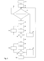
- Fig. 3 is a flowchart showing how a preset intensity ratio of the intensity in the main spectral region and the intensity in the sub-spectral region can be kept constant.
- the user has no influence on the sequence of the control described below.
- the control including monitoring of the preset intensity ratio, takes place in a very short time interval (for example, milliseconds), so that the control does not affect the user during use of the device 10.
- the first semiconductor illuminant 32 and the second semiconductor illuminant 34 are turned on (reference numeral 72). After switching on the semiconductor lamps 32 and 34, the starting point 73 of the control is reached.
- the semiconductor illuminants 32 and 34 emit light in the main spectral range and the sub-spectral range at a current or actual intensity ratio.
- the verification of the current or actual intensity ratio at 74 is performed at the beginning, ie after switching on the light source 70, and after any time intervals as well as with manual change of the brightness of the light source 12.
- the second semiconductor illuminant 34 which emits light in the secondary spectral range, is first switched off, so that only the first semiconductor illuminant 32, which emits light in the main spectral range, is switched on at 80.
- the intensity of the light emitted from the first semiconductor illuminant 32 is measured by the measuring device 57. The measurement can take place, for example, via an optical sensor, for example a photodiode of the measuring device 57. The measured value is then compared with reference values (reference numeral 86) for the preset intensity ratio at 84. If deviations of the measured intensity from the stored reference values occur, the current supply of the first semiconductor illuminant 32 is adjusted accordingly at 88.
- the comparison at 84 indicates that the intensity emitted by the first semiconductor illuminant 32 is correct, at 90 the first semiconductor illuminant 32 is turned off, while now at 92, only the second semiconductor illuminant 34 is turned on. In the following course of the flowchart, the appropriate intensity value of the emission of the second semiconductor illuminant 34 is determined. This process is analogous to the determination of the correct intensity value of the first semiconductor illuminant 32, i.
- the intensity of the emission of the second semiconductor illuminant 34 is measured, compared with reference values (reference numeral 96) for the preset intensity ratio and, optionally, an additionally adjustable intensity offset for the second semiconductor illuminant 34 at 98 and, if required, at 100 the energization of the second semiconductor bulb 34 is changed accordingly. If the comparison at 98 indicates that the intensity emitted by the second semiconductor illuminant 34 is correct, the first semiconductor illuminant 32 is switched on at 102 and the control returns to the starting point 73 again, and the monitoring of the preset intensity ratio begins again.
Abstract
Eine endoskopische, exoskopische oder mikroskopische Vorrichtung zur Fluoreszenzdiagnose weist eine Lichtquelle (12) auf, die dazu ausgelegt ist, in einem Fluoreszenzmodus Licht in einem ersten Spektralbereich und Licht in einem zweiten Spektralbereich zu emittieren, wobei der zweite Spektralbereich von dem ersten Spektralbereich zumindest teilweise getrennt ist. Die Lichtquelle (12) weist zumindest ein erstes Halbleiterleuchtmittel (32) auf, das im Fluoreszenzmodus das Licht in dem ersten Spektralbereich emittiert. Die Lichtquelle (12) weist zumindest ein zweites Halbleiterleuchtmittel (34) aufweist, das in dem Fluoreszenzmodus das Licht in dem zweiten Spektralbereich emittiert. Die Vorrichtung weist eine Steuer- oder Regeleinrichtung (56) auf, die ein voreingestelltes Verhältnis aus einer ersten Intensität des Lichts im ersten Spektralbereich und einer zweiten Intensität des Lichtes im zweiten Spektralbereich konstant hält.An endoscopic, exoscopic or microscopic device for fluorescence diagnosis has a light source (12) which is designed to emit light in a first spectral range and light in a second spectral range in a fluorescence mode, wherein the second spectral range is at least partially separated from the first spectral range is. The light source (12) has at least one first semiconductor illuminant (32) which emits the light in the first spectral range in fluorescence mode. The light source (12) has at least one second semiconductor illuminant (34) which emits the light in the second spectral range in the fluorescence mode. The device has a control or regulating device (56) which keeps a preset ratio of a first intensity of the light in the first spectral range and a second intensity of the light in the second spectral range constant.
Description
Die Erfindung betrifft eine endoskopische, exoskopische oder mikroskopische Vorrichtung zur Fluoreszenzdiagnose, mit einer Lichtquelle, die dazu ausgelegt ist, in einem Fluoreszenzmodus Licht in einem ersten Spektralbereich und Licht in einem zweiten Spektralbereich zu emittieren, wobei der zweite Spektralbereich von dem ersten Spektralbereich zumindest teilweise getrennt ist, wobei die Lichtquelle zumindest ein erstes Halbleiterleuchtmittel aufweist, das im Fluoreszenzmodus Licht in dem ersten Spektralbereich emittiert.The invention relates to an endoscopic, exoscopic or microscopic device for fluorescence diagnosis, comprising a light source which is adapted to emit light in a first spectral range and light in a second spectral range in a fluorescence mode, the second spectral range being at least partially separated from the first spectral range wherein the light source comprises at least a first semiconductor illuminant emitting in the fluorescence mode light in the first spectral range.
Eine solche Vorrichtung ist aus
Eine erfindungsgemäße Vorrichtung zur Fluoreszenzdiagnose der eingangs genannten Art wird vorzugsweise zu medizinischen Diagnosezwecken verwendet, kann aber auch zu technischen Diagnosezwecken in industriellen oder wissenschaftlichen Anwendungen verwendet werden.An inventive device for fluorescence diagnosis of the type mentioned above is preferably used for medical diagnostic purposes, but can also be used for technical diagnostic purposes in industrial or scientific applications.
Im Rahmen der medizinischen Fluoreszenzdiagnose wird eine Vorrichtung der eingangs genannten Art zur Beurteilung des Zustands von biologischem Gewebe, beispielsweise allgemein zur Gewebedifferenzierung, insbesondere zur Tumorerkennung, aber auch zur Erkennung der Durchblutung und Vitalität verwendet. Mit einer Vorrichtung zur Fluoreszenzdiagnose der eingangs genannten Art kann die Fluoreszenzdiagnose insbesondere in vivo durchgeführt werden.In the context of medical fluorescence diagnosis, a device of the type mentioned at the outset is used for assessing the condition of biological tissue, for example generally for tissue differentiation, in particular for tumor detection, but also for detecting perfusion and vitality. With a device for fluorescence diagnosis of the type mentioned above, the fluorescence diagnosis can be carried out in particular in vivo .
Im medizinischen Bereich hat sich die Fluoreszenzdiagnose zu einer vielversprechenden Alternative bzw. Ergänzung in der Erkennung und Behandlung neoplastischer Veränderungen entwickelt. Die Fluoreszenzdiagnose beruht auf der Wechselwirkung von Licht einer geeigneten Wellenlänge mit einer im zu untersuchenden Gewebeareal vorhandenen fluoreszierenden Substanz. Dabei kann eine fluoreszierende Substanz ein Fluoreszenzfarbstoff sein, der zuvor in das zu untersuchende Gewebeareal eingebracht wurde, beispielsweise durch Verabreichen der fluoreszierenden Substanz selbst oder einer Vorstufe derselben an den zu untersuchenden Patienten. Eine fluoreszierende Substanz kann jedoch auch eine bereits im Zielgebiet vorhandene Substanz sein, beispielsweise eine gewebespezifische Substanz, die durch Licht in einem geeigneten Spektralbereich zur Autofluoreszenz angeregt wird. Die vorliegende Erfindung kann beide Fälle umfassen. Für die nachfolgenden Erläuterungen wird von dem Fall ausgegangen, dass die fluoreszierende Substanz ein Fluoreszenzfarbstoff ist, der exogen (von außen) in das zu untersuchende Gewebeareal eingebracht wird.In the medical field, fluorescence diagnosis has become a promising alternative or supplement to the detection and treatment of neoplastic changes. The fluorescence diagnosis is based on the interaction of light of a suitable wavelength with a fluorescent substance present in the tissue area to be examined. In this case, a fluorescent substance may be a fluorescent dye which has been previously introduced into the tissue area to be examined, for example by administering the fluorescent substance itself or a precursor thereof to the patient to be examined. However, a fluorescent substance may also be a substance already present in the target area, for example a tissue-specific substance which is excited to autofluorescence by light in a suitable spectral range. The present invention may include both cases. For the following explanations, it is assumed that the fluorescent substance is a fluorescent dye which is introduced exogenously (from the outside) into the tissue area to be examined.
Bei den tumorselektiven Substanzen wird derzeit der 5-Aminolävulinsäure(5-ALA) bzw. ihrem Hexylester (5-ALAHE, Handelsname Hexvix®) eine entscheidende Rolle beigemessen. Sie ist eine körpereigene Substanz und Ausgangsprodukt der intrazellulären Hämbiosynthese. Nach mehreren Reaktionsschritten werden intrazellulär endogene Porphyrine, in erster Linie das Protoporphyrin IX (PPIX), synthetisiert. Letzteres ist das entscheidende Fluorochrom, das während der fluoreszenzdiagnostischen Untersuchung nachgewiesen wird. Dies gelingt allerdings nur, wenn 5-ALA in ausreichender Konzentration den befallenen Organen exogen zugeführt wird.In the case of tumor-selective substances, 5-aminolevulinic acid (5-ALA) or its hexyl ester (5-ALAHE, trade name Hexvix®) is currently considered to play a crucial role. It is an endogenous substance and the starting material of intracellular heme biosynthesis. After several reaction steps, intracellular endogenous porphyrins, primarily protoporphyrin IX (PPIX), are synthesized. The latter is the crucial fluorochrome detected during the fluorescence diagnostic study. However, this succeeds only if 5-ALA is supplied exogenously in sufficient concentration to the affected organs.
In derzeitigen Fluoreszenzdiagnosevorrichtungen wird als Lichtquelle eine Xenonlampe verwendet, die über ein flexibles Lichtübertragungssystem Fluoreszenzanregungslicht in ein Endoskop einkoppelt. Zur videotechnischen Dokumentation wird ein für die Fluoreszenzdiagnose angepasstes Kamerasystem eingesetzt.In current fluorescence diagnostic devices, a xenon lamp is used as the light source, which couples fluorescence excitation light into an endoscope via a flexible light transmission system. For video documentation, a camera system adapted for fluorescence diagnosis is used.
Im Falle der herkömmlichen Fluoreszenzdiagnosesysteme, die eine Xenonlampen-basierte Lichtquelle aufweisen, werden im Beleuchtungsstrahlengang ein Beleuchtungsfilter und im Beobachtungsstrahlengang ein Beobachtungsfilter eingesetzt. Die spektralen Transmissionseigenschaften des Beleuchtungsfilters und des Beobachtungsfilters bestimmen zusammen die Intensität des zurückgestreuten kurzwelligen, im Falle von PPIX blauen Anregungslichtes, das der Beobachter wahrnimmt. Für einen optimalen Kontrast zwischen fluoreszierendem und nicht fluoreszierendem Gewebe darf das zur Detektion gelangende remittierte Blaulicht nicht zu intensiv sein, da es sonst die Fluoreszenz, im Fall von PPIX Rotfluoreszenz, zu stark überlagert. Andererseits ist eine gewisse Mindestbeimischung von remittiertem Blaulicht, die sog. Blauzunge, wünschenswert, um die Diagnostik zu verbessern. Es ist bekannt, dass zurückgestreutes Licht und Fluoreszenzlicht ungefähr vergleichbare Intensität aufweisen sollten, um einen guten Farbkontrast zu erhalten.In the case of the conventional fluorescence diagnosis systems which have a xenon lamp-based light source, an illumination filter is used in the illumination beam path and an observation filter is used in the observation beam path. The spectral transmission properties of the illumination filter and the observation filter together determine the intensity of the backscattered short-wavelength, in the case of PPIX blue excitation light, which the observer perceives. For optimal contrast between fluorescent and non-fluorescent tissue, the remitted blue light for detection should not be too intense, otherwise the fluorescence, in the case of PPIX red fluorescence, will be too much superimposed. On the other hand, a certain minimum addition of remitted blue light, the so-called bluetongue, is desirable in order to improve diagnostics. It is known that backscattered light and fluorescent light should have approximately comparable intensity in order to obtain a good color contrast.
Ohne Beschränkung der Allgemeinheit ist im vorstehenden Sinne der erste Spektralbereich der Hauptspektralbereich der Anregung der Fluoreszenz, und der zweite Spektralbereich ist ein Nebenspektralbereich (beispielsweise die Blauzunge), wobei Licht in dem Nebenspektralbereich dem Fluoreszenzbild beigemischt wird.Without limitation of generality, in the above sense, the first spectral range is the main spectral range of excitation of the fluorescence, and the second spectral range is a sub-spectral range (for example, the blue tone), with light in the sub-spectral range being admixed with the fluorescence image.
Einen Nachteil einer Xenonlampen-basierten Lichtquelle stellt die relativ kurze Lebensdauer von Xenonlampen dar. Hersteller von Fluoreszenzdiagnosesystemen empfehlen daher, die Xenonlampe bzw. das Lampenmodul nach einer gewissen, relativ niedrigen Betriebsstundenzahl auszutauschen. Der Nachteil solcher herkömmlicher Fluoreszenzdiagnosesysteme besteht daher zum einen in dem durch den Austausch der Xenonlampe bedingten Kostenmehraufwand und die Stillstandszeiten, die durch die Wartung bzw. den Austausch bedingt sind.A disadvantage of a xenon lamp-based light source is the relatively short life of xenon lamps. Manufacturers of fluorescence diagnostic systems therefore recommend replacing the xenon lamp or the lamp module after a certain, relatively low number of operating hours. The disadvantage of such conventional Fluorescence diagnostic systems therefore consist, on the one hand, of the cost overhead caused by the replacement of the xenon lamp and the downtimes caused by maintenance or replacement.
Demgegenüber besitzen Halbleiterleuchtmittel wie Leuchtdioden, worunter in der vorliegenden Anmeldung sowohl anorganische als auch organische Halbleiterleuchtmittel zu verstehen sind, wie Leuchtdioden, Laserdioden, Superlumineszenzdioden und dgl., eine deutlich höhere Lebensdauer, wodurch die vorstehend genannten Nachteile vermieden werden können. Halbleiterleuchtmittel weisen heutzutage auch eine ausreichende Strahlungsleistung von mehreren Watt auf.In contrast, have semiconductor light-emitting devices such as light-emitting diodes, which are understood in the present application both inorganic and organic semiconductor lamps, such as light-emitting diodes, laser diodes, super-luminescent diodes and the like., A significantly higher life, whereby the above-mentioned disadvantages can be avoided. Semiconductor lamps today also have a sufficient radiation power of several watts.
In dem eingangs genannten Dokument
Aus
Als Lichtquelle, die sowohl die Anregungslichtquelle als auch die weitere Lichtquelle bildet, wird dort wie herkömmliich eine breitbandige Lichtquelle, beispielsweise eine Halogenlampe, verwendet, mit den zuvor beschriebenen Nachteilen.As a light source, which forms both the excitation light source and the further light source, there is used as herkömmliich a broadband light source, such as a halogen lamp, with the disadvantages described above.
Während Halbleiterleuchtmittel im Vergleich zu Xenonlampen-basierten Lichtquellen eine hohe Lebensdauer besitzen, variieren die optischen Eigenschaften von Halbleiterleuchtmitteln, z.B. die Zentralwellenlänge, die Halbwertsbreite und die Strahlungsleistung durch den Herstellungsprozess innerhalb bestimmter Grenzen. Darüber hinaus werden die optischen Eigenschaften sowie die Lebensdauer von Halbleiterleuchtmitteln durch Betriebsparameter, wie beispielsweise Stromstärke, Spannung und Temperatur, beeinflusst. Die optischen Eigenschaften können sich während des Betriebes (in der Regel) reversibel oder aber im Laufe der Lebensdauer (in der Regel) irreversibel ändern. Dies kann bei einem Einsatz derartiger Lichtquellen dazu führen, dass sich der Farbkontrast während einer Sitzung oder im Laufe der Zeit unerwünscht ändert, wodurch eine sichere Diagnose nicht gewährleistet ist.While semiconductor lamps have a long life compared to xenon lamp-based light sources, the optical properties of semiconductor lamps, e.g. the central wavelength, the half-width and the radiation power through the manufacturing process within certain limits. In addition, the optical properties as well as the lifetime of semiconductor lamps are influenced by operating parameters such as current, voltage and temperature. The optical properties can (usually) change irreversibly during operation (usually) reversibly or during the lifetime (usually). This may result in the use of such light sources that the color contrast changes undesirably during a session or over time, whereby a reliable diagnosis is not guaranteed.
Der Erfindung liegt die Aufgabe zugrunde, eine Vorrichtung der eingangs genannten Art dahingehend weiterzubilden, dass der für eine sichere Diagnose erforderliche Farbkontrast im Fluoreszenzbild gleich bleibt, und dies während einer Diagnosesitzung, als auch über die Lebensdauer der Lichtquelle.The invention has the object of developing a device of the type mentioned in that the required for a reliable diagnosis of color contrast in the fluorescence image remains the same, and this during a diagnostic session, as well as the life of the light source.
Erfindungsgemäß wird diese Aufgabe hinsichtlich der eingangs genannten endoskopischen, exoskopischen oder mikroskopischen Vorrichtung zur Fluoreszenzdiagnose dadurch gelöst, dass die Lichtquelle zumindest ein zweites Halbleiterleuchtmittel aufweist, das in dem Fluoreszenzmodus das Licht in dem zweiten Spektralbereich emittiert, und durch eine Steuer- oder Regeleinrichtung, die ein voreingestelltes Verhältnis aus einer ersten Intensität des Lichtes im ersten Spektralbereich und einer zweiten Intensität des Lichtes im zweiten Spektralbereich konstant hält.According to the invention this object is achieved in terms of the above-mentioned endoscopic, exoscopic or microscopic device for fluorescence diagnosis in that the light source has at least a second semiconductor illuminant which emits the light in the second spectral range in the fluorescence mode, and by a control or regulating device, the Preset ratio of a first intensity of the light in the first spectral range and a second intensity of the light in the second spectral range keeps constant.
Die erfindungsgemäße Vorrichtung zur Fluoreszenzdiagnose weist somit zur Emission von Licht im Anregungsspektralbereich als auch zur Emission von Licht im Nebenspektralbereich (beispielsweise für die Blauzunge) Halbleiterleuchtmittel auf. Hierdurch wird zunächst der Nachteil einer vergleichsweise kurzen Lebensdauer herkömmlicher Lichtquellen von Fluoreszenzdiagnosevorrichtungen, die Xenon- oder Halogenlampen-basierte Lichtquellen aufweisen, behoben. Das technische Problem des Driftens der optischen Eigenschaften von Halbleiterleuchtmitteln wird durch eine Steuer- oder Regeleinrichtung behoben, die ein voreingestelltes Verhältnis der Lichtintensitäten im ersten Spektralbereich und im zweiten Spektralbereich konstant hält. Das voreingestellte Verhältnis der vorstehend genannten Lichtintensitäten ist dabei nicht benutzerbestimmt, sondern vorzugsweise zuvor klinisch ermittelt und in der Fluoreszenzdiagnosevorrichtung, insbesondere in der Steuer- oder Regeleinrichtung derselben, hinterlegt. Die Steuer- oder Regeleinrichtung der erfindungsgemäßen Fluoreszenzdiagnosevorrichtung sorgt nun dafür, dass das voreingestellte Intensitätsverhältnis sowohl im Rahmen einer Diagnosesitzung als auch über die Lebensdauer der Lichtquelle, d.h. die Lebensdauer der Halbleiterleuchtmittel, beibehalten wird, d.h. auch unabhängig von Betriebsparametern wie Stromstärke, Spannung und Temperatur und unabhängig von der Alterung der Halbleiterleuchtmittel. Die erfindungsgemäße Fluoreszenzdiagnosevorrichtung gewährleistet somit stets einen für eine sichere Diagnose erforderlichen gleichbleibenden Farbkontrast im Fluoreszenzbild.The device according to the invention for fluorescence diagnosis thus has semiconductor light emitting means for emitting light in the excitation spectral range as well as for emitting light in the secondary spectral range (for example for the blue tongue). As a result, the disadvantage of a comparatively short life of conventional light sources of fluorescence diagnosis devices which have xenon or halogen lamp-based light sources is initially eliminated. The technical problem of drifting the optical properties of semiconductor light sources is remedied by a control or regulating device which keeps constant a preset ratio of the light intensities in the first spectral range and in the second spectral range. The preset ratio of the abovementioned light intensities is not user-defined, but preferably clinically determined beforehand and stored in the fluorescence diagnosis device, in particular in the control or regulating device thereof. The control or regulation device of the fluorescence diagnosis device according to the invention now ensures that the preset intensity ratio both during a diagnostic session and over the life of the light source, i. the lifetime of the semiconductor illuminants is maintained, i. also independent of operating parameters such as current, voltage and temperature and independent of the aging of the semiconductor lamps. The fluorescence diagnosis device according to the invention thus always ensures a constant color contrast in the fluorescence image which is necessary for a reliable diagnosis.
Die Steuer- oder Regeleinrichtung kann als Steuereinrichtung oder als Regeleinrichtung ausgebildet sein. Die Steuer- oder Regeleinrichtung kann so ausgebildet sein, dass sie die Beaufschlagung zumindest eines der Halbleiterleuchtmittel mit Strom und/oder Spannung steuert oder regelt. Sie kann auch eine Steuerung oder Regelung der Temperatur zumindest eines der Halbleiterleuchtmittel mittels einer Kühlung/Heizung bewirken, um das voreingestellte Intensitätsverhältnis konstant zu halten.The control or regulating device can be designed as a control device or as a control device. The control or regulating device may be designed such that it controls or regulates the application of current and / or voltage to at least one of the semiconductor illuminants. It may also cause control or regulation of the temperature of at least one of the semiconductor illuminants by means of cooling / heating in order to keep the preset intensity ratio constant.
Die Steuer- oder Regeleinrichtung kann insbesondere dazu ausgelegt sein, das voreingestellte Verhältnis aus der ersten und der zweiten Intensität auf Änderungen hin zu überwachen und bei detektierten Änderungen das Ist-Verhältnis auf das voreingestellte Verhältnis zurückzusetzen. Letzteres kann dadurch bewerkstelligt werden, dass die Steuer- oder Regeleinrichtung die Stromstärke und/oder Spannung, mit der bzw. denen zumindest eines der Halbleiterleuchtmittel betrieben wird, steuert oder regelt.In particular, the control or regulating device may be designed to monitor the preset ratio of the first and the second intensity for changes and to reset the actual ratio to the preset ratio when changes are detected. The latter can be accomplished by the control or regulating device controls or regulates the current intensity and / or voltage with which at least one of the semiconductor illuminants is operated.
Der Vorteil einer Überwachung des voreingestellten Intensitätsverhältnisses besteht vor allem darin, dass individuelle Eigenschaften der einzelnen Halbleiterleuchtmittel, die von Halbleiterleuchtmittel zu Halbleiterleuchtmittel unterschiedlich sein können, stets bei der Steuerung oder Regelung berücksichtigt werden können, insbesondere individuelle Unterschiede der Halbleiterleuchtmittel, die sich erst oder vor allem im Laufe der Alterung der Halbleiterleuchtmittel ergeben.The advantage of monitoring the preset intensity ratio is, above all, that individual properties of the individual semiconductor illuminants, which may differ from semiconductor illuminant to semiconductor illuminant, can always be taken into account in the control or regulation, in particular individual differences of the semiconductor illuminants that are first or foremost in the course of aging of the semiconductor lamps.
In einer bevorzugten Ausgestaltung der vorstehend genannten Maßnahme weist die Steuer- oder Regeleinrichtung eine Messeinrichtung zum Messen der Intensitäten des von dem ersten Halbleiterleuchtmittel und dem zumindest einen zweiten Halbleiterleuchtmittel emittierten Lichts auf.In a preferred embodiment of the aforementioned measure, the control or regulating device has a measuring device for measuring the intensities of the light emitted by the first semiconductor illuminant and the at least one second semiconductor illuminant.
Diese Ausgestaltung einer Überwachung des voreingestellten Intensitätsverhältnisses ist vorteilhafterweise einfach zu realisieren, insbesondere kann als Messeinrichtung eine Photodiode verwendet werden, die auf Helligkeitsänderungen mit einer Änderung der Strom-Spannungs-Kennlinie der Photodiode reagiert.This embodiment of a monitoring of the preset intensity ratio is advantageously easy to implement, in particular, as a measuring device, a photodiode can be used, which responds to changes in brightness with a change in the current-voltage characteristic of the photodiode.
Die erfindungsgemäße Vorrichtung ist, wie bei herkömmlichen Fluoreszenzdiagnosevorrichtungen, vorzugsweise auch mit einer Bilderfassungseinrichtung zur Erfassung eines Fluoreszenzbildes ausgestattet. Hierbei ist es bevorzugt, wenn die Steuer- oder Regeleinrichtung Bildsignale der Bilderfassungseinrichtung auswertet, um das voreingestellte Verhältnis auf Änderungen zu überwachen.The device according to the invention is, as in conventional fluorescence diagnosis devices, preferably also equipped with an image capture device for acquiring a fluorescence image. In this case, it is preferable for the control or regulating device to evaluate image signals of the image acquisition device in order to monitor the preset ratio for changes.
In dieser Ausgestaltung ist die Basis der Konstanthaltung des voreingestellten Intensitätsverhältnisses vorteilhafterweise das Fluoreszenzbild bzw. dessen Kontrast selbst, wobei Änderungen des voreingestellten Intensitätsverhältnisses, die sich in einer Änderung des Farbkontrastes im Fluoreszenzbild äußern, von der Bilderfassungseinrichtung erfasst und von der Steuer- oder Regeleinrichtung instantan zur Nachführung des Intensitäts-Ist-Verhältnisses auf das voreingestellte Intensitätsverhältnis verwendet werden.In this embodiment, the basis of keeping constant the preset intensity ratio is advantageously the fluorescence image or its contrast itself, wherein changes in the preset intensity ratio, which manifest themselves in a change in color contrast in the fluorescence image, detected by the image capture device and instantaneously from the control or regulating device tracking of the intensity-actual ratio to the preset intensity ratio.
Alternativ zu einer Überwachung des Ist-Verhältnisses auf Abweichungen zu dem voreingestellten Intensitätsverhältnis kann in der Steuer- oder Regeleinrichtung ein typischer zeitlicher Verlauf von Änderungen der Intensitäten des von dem ersten Halbleiterleuchtmittel und dem zumindest einen zweiten Halbleiterleuchtmittel emittierten Lichts gespeichert sein, wobei die Steuer- oder Regeleinrichtung anhand des typischen zeitlichen Verlaufes der Änderungen Korrekturwerte berechnet, um das voreingestellte Verhältnis konstant zu halten.As an alternative to monitoring the actual ratio for deviations from the preset intensity ratio, the control device may store a typical time profile of changes in the intensities of the light emitted by the first semiconductor illuminant and the at least one second semiconductor illuminant, wherein the control or Control device based on the typical time course of the changes calculated correction values to keep the preset ratio constant.
Diese Maßnahme beruht darauf, dass ein gleichbleibender Farbkontrast aufeinander abgestimmte Stromstärken des Halbleiterleuchtmittels, das das Anregungslicht emittiert, und des Halbleiterleuchtmittels, das den Nebenspektralbereich emittiert, voraussetzt. Die hierzu erforderlichen Stromstärken der Halbleiterleuchtmittel können experimentell im Labor und/oder in einer klinischen Evaluierung ermittelt werden. Diese ermittelten Werte werden anschließend in der Fluoreszenzdiagnosevorrichtung, beispielsweise in einem Speicherbaustein, der in der Anregungslichtquelle hinterlegt sein kann, abgespeichert. In dieser Ausgestaltung der Vorrichtung ist die Steuer- oder Regeleinrichtung zumindest in der Lage, ein auf Erfahrungswerten beruhendes Driften des voreingestellten Intensitätsverhältnisses auszugleichen, wobei das Konstanthalten des voreingestellten Intensitätsverhältnisses möglicherweise einer Toleranz unterliegt. In diesem Fall findet lediglich eine Steuerung der Stromstärke zumindest eines der Halbleiterleuchtmittel statt, jedoch keine Regelung. Nichtsdestoweniger hat diese Ausgestaltung den Vorteil eines einfacheren Aufbaus und einer geringeren Komplexität, weil keine Überwachung des Ist-Intensitätsverhältnisses erforderlich ist.This measure is based on the fact that a constant color contrast presupposes matched current levels of the semiconductor illuminant emitting the excitation light and the semiconductor illuminant emitting the subspectral range. The required currents of the semiconductor lamps can be determined experimentally in the laboratory and / or in a clinical evaluation. These determined values are then stored in the fluorescence diagnosis device, for example in a memory module which may be stored in the excitation light source. In this embodiment of the device, the controller is at least capable of compensating for drifting of the preset intensity ratio based on empirical values, wherein the keeping constant of the preset intensity ratio may be subject to a tolerance. In this case, only a control of the current intensity of at least one of the semiconductor lamps takes place, but no control. Nevertheless, this design has the advantage of simpler construction and less complexity because no monitoring of the actual intensity ratio is required.
Vorzugsweise ist die Steuer- oder Regeleinrichtung in die Lichtquelle integriert.Preferably, the control or regulating device is integrated in the light source.
Der Vorteil hierbei ist eine kompakte Bauweise der Fluoreszenzdiagnosevorrichtung.The advantage here is a compact design of the fluorescence diagnostic device.
Das zumindest eine erste Halbleiterleuchtmittel und/oder das zumindest eine zweite Halbleiterleuchtmittel ist bzw. sind eine Leuchtdiode (anorganisch (LED) oder organisch (OLED)), worunter auch eine Superlumineszenzdiode zu verstehen ist, eine Laserdiode, ein Leuchtdiodenarray oder ein Laserdiodenarray.The at least one first semiconductor illuminant and / or the at least one second semiconductor illuminant is or are a light-emitting diode (inorganic (LED) or organic (OLED)), which is also to be understood as a superluminescent diode, a laser diode, a light-emitting diode array or a laser diode array.
Vorzugsweise weist die Lichtquelle zumindest ein, vorzugsweise mehrere weitere Halbleiterleuchtmittel auf, die in einem Weißlichtmodus Weißlicht erzeugen.The light source preferably has at least one, preferably a plurality of further semiconductor illuminants which generate white light in a white-light mode.
So kann die Lichtquelle zusätzlich eine weiße Leuchtdiode oder ein Leuchtdiodenarray mit roten, grünen und blauen LEDs aufweisen, die in Kombination miteinander Weißlicht erzeugen.Thus, the light source can additionally comprise a white light-emitting diode or a light-emitting diode array with red, green and blue LEDs, which generate white light in combination with each other.
Die erfindungsgemäße Vorrichtung kann vorzugsweise zwischen dem Fluoreszenzmodus und dem Weißlichtmodus umgeschaltet werden, wobei der Weißlichtmodus zur Orientierung des Benutzers im beobachteten Areal dient. Im Zusammenhang mit den vorstehend genannten Maßnahmen ist es bevorzugt, wenn das zweite Halbleiterleuchtmittel eine einzelne Leuchtdiode ist, die im Fluoreszenzmodus nur zusammen mit dem ersten Halbleiterleuchtmittel aktiv ist, während das zweite Halbleiterleuchtmittel im Weißlichtmodus mit den weiteren Halbleiterleuchtmitteln zur Erzeugung von Weißlicht aktiv ist.The device according to the invention can preferably be switched between the fluorescence mode and the white light mode, the white light mode serving to orient the user in the observed area. In connection with the abovementioned measures, it is preferred if the second semiconductor illuminant is a single light-emitting diode which is active only in the fluorescence mode together with the first semiconductor illuminant, while the second semiconductor illuminant is active in the white light mode with the further semiconductor illuminants for generating white light.
Das zweite Halbleiterleuchtmittel wird demnach im Fluoreszenzmodus zusammen mit dem ersten Halbleiterleuchtmittel aktiviert, wobei das zweite Halbleiterleuchtmittel dann Licht im zweiten Spektralbereich (Nebenspektralbereich, beispielsweise für die Blauzunge) zur optimalen Farbkontrastgebung im Fluoreszenzbild verwendet wird, während das zweite Halbleiterleuchtmittel im Weißlichtmodus in Kombination mit den weiteren Halbleiterleuchtmitteln zur Weißlichterzeugung aktiviert wird. Im Fall einer Fluoreszenzdiagnose mittels PPIX emittiert das zweite Halbleiterleuchtmittel zur Erzeugung der Blauzunge im blauen Spektralbereich.The second semiconductor illuminant is thus activated in fluorescence mode together with the first semiconductor illuminant, the second semiconductor illuminant then light in the second spectral range (Nebenspektralbereich, for example, the blue tongue) is used for optimum color contrast in fluorescence image, while the second semiconductor illuminant in the white light mode in combination with the other Semiconductor lighting for white light generation is activated. In the case of a fluorescence diagnosis by means of PPIX, the second semiconductor illuminant emits to produce the blue tongue in the blue spectral range.
Vorzugsweise weist die Vorrichtung des Weiteren eine Umschaltsteuerung zum Umschalten zwischen dem Fluoreszenzmodus und dem Weißlichtmodus auf, wobei die Umschaltsteuerung zum Umschalten zwischen dem Fluoreszenzmodus und dem Weißlichtmodus das zumindest eine erste Halbleiterleuchtmittel, das zumindest eine zweite Halbleiterleuchtmittel und das zumindest eine weitere Halbleiterleuchtmittel schaltet.Preferably, the device further comprises a switching control for switching between the fluorescence mode and the white light mode, wherein the switching controller for switching between the fluorescence mode and the white light mode switches the at least one first semiconductor illuminant, the at least one second semiconductor illuminant, and the at least one further semiconductor illuminant.
Während bei herkömmlichen Fluoreszenzdiagnosevorrichtungen zur Umschaltung zwischen dem Fluoreszenz- und dem Weißlichtmodus der Autoshutter des Bildaufnahmechips benutzt wird, hat die vorstehend genannte Maßnahme den Vorteil, dass auf einen Autoshutter verzichtet werden kann.While in conventional fluorescence diagnostic devices for switching between the fluorescent and the white light mode of the autoshutter of the image pickup chip is used, the above measure has the advantage that can be dispensed with a car shutter.
In einer weiteren bevorzugten Ausgestaltung sind in einem Speicher eine Mehrzahl von unterschiedlichen voreingestellten Verhältnissen aus der ersten und der zweiten Intensität abgespeichert, zwischen denen wahlweise umgeschaltet werden kann, wobei die Steuer- und Regeleinrichtung das jeweils gewählte voreingestellte Verhältnis konstant hält.In a further preferred embodiment, a plurality of different preset ratios of the first and the second intensity are stored in a memory, between which can be selectively switched, wherein the control and regulating device keeps the respectively selected preset ratio constant.
Wie bereits oben erwähnt, ist es in der Regel erforderlich, den optimalen Farbkontrast, d.h. die optimale Beimischung von Licht in einem Nebenspektralbereich der Anregung, beispielsweise von Blaulicht, in einer klinischen Evaluierung zu ermitteln. Nun kann der optimale Farbkontrast bei verschiedenen Anwendungen (z.B. verschiedenen Organen, verschiedenen diagnostischen Aufgaben, ...) unterschiedlich ausfallen, d.h. es kann unterschiedliche voreingestellte Intensitätsverhältnisse für unterschiedliche Organe geben. Dem trägt die vorstehend genannte Maßnahme vorteilhafterweise Rechnung. Die Steuer- und Regeleinrichtung hält auch in diesem Fall das jeweilige voreingestellte Intensitätsverhältnis konstant.As mentioned above, it is usually necessary to have the optimum color contrast, i. to determine the optimal admixture of light in a secondary spectral region of excitation, for example, blue light, in a clinical evaluation. Now the optimal color contrast may be different in different applications (e.g., different organs, different diagnostic tasks, ...), i. There may be different preset intensity ratios for different organs. The aforementioned measure advantageously takes account of this. The control device also keeps the respective preset intensity ratio constant in this case.
Ebenso bevorzugt ist es, wenn die Lichtquelle eine Mehrzahl von zweiten Halbleiterleuchtmitteln aufweist, die jeweils Licht in unterschiedlichen voreingestellten zweiten Spektralbereichen erzeugen, wobei zwischen den unterschiedlichen zweiten Spektralbereichen wahlweise umgeschaltet werden kann.It is likewise preferred if the light source has a plurality of second semiconductor illuminants which respectively generate light in different preset second spectral ranges, it being possible to switch between the different second spectral ranges as desired.
Diese Ausgestaltung hat zum einen den Vorteil, dass die Fluoreszenzdiagnosevorrichtung auf unterschiedliche Fluoreszenzfarbstoffe ausgelegt werden kann, weil sie Licht in unterschiedlichen Nebenspektralbereichen erzeugen kann. Aber auch im Fall ein und desselben Fluoreszenzfarbstoffes hat diese Maßnahme den Vorteil, dass dem Fluoreszenzbild Licht aus verschiedenen Nebenspektralbereichen beigemischt werden kann, um einen für die Diagnose optimalen Farbkontrast zu erhalten.On the one hand, this refinement has the advantage that the fluorescence diagnosis device can be designed for different fluorescent dyes because it can generate light in different secondary spectral ranges. However, even in the case of one and the same fluorescent dye, this measure has the advantage that light from different secondary spectral regions can be added to the fluorescence image in order to obtain a color contrast which is optimal for the diagnosis.
In einer weiteren bevorzugten Ausgestaltung ist zwischen dem zumindest einen ersten Halbleiterleuchtmittel und dem zumindest einen zweiten Halbleiterleuchtmittel ein Strahlkombinationselement angeordnet.In a further preferred refinement, a beam combination element is arranged between the at least one first semiconductor illuminant and the at least one second semiconductor illuminant.
Hierbei ist von Vorteil, dass das erste Halbleiterleuchtmittel und das zumindest eine zweite Halbleiterleuchtmittel nicht auf einer gemeinsamen optischen Achse angeordnet werden müssen, was zu räumlichen Konflikten führen würde, sondern die beiden Halbleiterleuchtmittel können mit sich schneidenden Abstrahlachsen angeordnet werden. Das Strahlkombinationselement kann beispielsweise eine Planplatte mit reflektierender Vorderseite und für Licht im betreffenden Spektralbereich durchlässiger Rückseite sein.It is advantageous that the first semiconductor illuminant and the at least one second semiconductor illuminant need not be arranged on a common optical axis, which would lead to spatial conflicts, but the two semiconductor illuminants can be arranged with intersecting emission axes. The beam combination element can, for example, be a plane plate with a reflective front and a light-transmissive back for light in the relevant spectral range.
Des Weiteren kann dem zumindest einen Halbleiterleuchtmittel und dem zumindest einen zweiten Halbleiterleuchtmittel zumindest ein optisches Element zur Kollimation nachgeordnet sein, das vorzugsweise asphärisiert ist.Furthermore, at least one optical element for collimation, which is preferably aspherical, may be arranged downstream of the at least one semiconductor illuminant and the at least one second semiconductor illuminant.
Eine Fokussieroptik hat den Vorteil, dass das von den Halbleiterleuchtmitteln ungebündelt emittierte Licht zur Einkopplung in einen Lichtleiter gebündelt werden kann, der mit einem Endoskop, Exoskop oder einem Mikroskop verbunden ist, so dass Intensitätsverluste bei der Einkopplung des Lichts in den Lichtleiter so gering wie möglich gehalten werden können.Focusing optics have the advantage that the light emitted unbundled by the semiconductor illuminants can be bundled for coupling into a light guide, which is connected to an endoscope, exoscope or a microscope, so that intensity losses during the coupling of the light into the light guide are as small as possible can be kept.
In einer weiteren bevorzugten Ausgestaltung ist der zumindest eine zweite Spektralbereich, in dem das zumindest eine zweite Halbleiterleuchtmittel Licht erzeugt, schmalbandig, und im Fall der Verwendung der Fluoreszenzdiagnosevorrichtung mit dem Fluoreszenzfarbstoff PPIX erzeugt das zweite Halbleiterleuchtmittel Licht vorzugsweise mit einer Peak-Wellenlänge im Bereich von etwa 400 nm bis etwa 500 nm, vorzugsweise von etwa 450 nm.In a further preferred refinement, the at least one second spectral range in which the at least one second semiconductor illuminant generates light is narrow band, and in the case of using the fluorescence diagnosis apparatus With the fluorescent dye PPIX, the second semiconductor illuminant preferably generates light having a peak wavelength in the range of about 400 nm to about 500 nm, preferably about 450 nm.
Die Schmalbandigkeit des zweiten Halbleiterleuchtmittels zur Erzeugung des Nebenspektralbereichs (im Falle von PPIX die Blauzunge) hat den Vorteil, dass bei geschicktem Abgleich zwischen den Intensitäten des Nebenspektralbereichs und des Hauptspektralbereichs eine Rotfluoreszenz mit einem anderen Farbkontrast im Fluoreszenzbild erscheint, wenn die Fluoreszenz intensiv ist, was auf malignes Gewebe hinweist, als wenn die Fluoreszenz schwach ist, d.h. kein spezifischer Befund vorliegt.The narrowbandness of the second semiconductor illuminant for generating the sub-spectral region (in the case of PPIX, the blue tongue) has the advantage that, when skilful matching between the intensities of the sub-spectral region and the main spectral region, a red fluorescence with a different color contrast appears in the fluorescence image, if the fluorescence is intense, which indicates malignant tissue as if the fluorescence is weak, ie no specific finding is available.
In einer weiteren bevorzugten Ausgestaltung kann das voreingestellte Verhältnis aus erster Intensität und zweiter Intensität während des Betriebes kontinuierlich oder diskret verändert werden.In a further preferred embodiment, the preset ratio of first intensity and second intensity during operation can be changed continuously or discretely.
Es wurde oben erwähnt, dass der Benutzer keine freie Wahl des Intensitätsverhältnisses haben sollte, da dies die Gefahr falsch positiver und vor allem falsch negativer Diagnosestellung birgt. Die vorstehende Maßnahme hat jedoch den Vorteil, beispielsweise bei der Schulung von Ärzten, dass in nicht-diagnostischen Situationen auch veränderte bzw. zusätzliche Werte vorgegeben werden können. Hierdurch kann bei einer Schulung demonstriert werden, wie sich eine Änderung des voreingestellten Verhältnisses der Intensitäten im Haupt- und Nebenspektralbereich auf den Farbkontrast und damit auf die Diagnose auswirken können. Auch für erfahrene Spezialisten auf dem Gebiet der Fluoreszenzdiagnose kann diese Wahlmöglichkeit nützlich sein.It was mentioned above that the user should not have a free choice of the intensity ratio, since this carries the risk of false positive and above all false negative diagnosis. However, the above measure has the advantage, for example in the training of doctors, that in non-diagnostic situations also changed or additional values can be specified. This can be used as a training to demonstrate how a change in the preset ratio of intensities in the main and minor spectral regions can affect the color contrast and thus the diagnosis. Even for experienced specialists in the field of fluorescence diagnosis, this choice may be useful.
Der Anwender kann einen anderen Wert für das Intensitätsverhältnis zwischen Haupt- und Nebenspektralbereich als das voreingestellte Intensitätsverhältnis wählen, wobei das gewählte Intensitätsverhältnis beispielsweise um einen Faktor zwischen 1,05 und 100, bevorzugt 1,1 und 20 gegenüber dem voreingestellten bzw. voreingestellten abweichen kann. Dabei kann des Weiteren vorgesehen sein, dass zwischen verschiedenen fest voreingestellten Intensitätsverhältnissen gewählt werden kann, dass andere als die fest voreingestellten Intensitätsverhältnisse gewählt werden können oder dass das voreingestellte Intensitätsverhältnis zeitlich befristet umgeschaltet werden kann.The user may choose another value for the intensity ratio between the main and sub-spectral range than the preset intensity ratio, wherein the selected intensity ratio may differ, for example, by a factor between 1.05 and 100, preferably 1.1 and 20, compared to the preset or preset. It can further be provided that it is possible to choose between different fixed preset intensity ratios other than the fixed preset intensity ratios can be selected or that the preset intensity ratio can be switched temporarily limited.
Weitere Vorteile und Merkmale ergeben sich aus der nachfolgenden Beschreibung und der beigefügten Zeichnung.Further advantages and features will become apparent from the following description and the accompanying drawings.
Es versteht sich, dass die vorstehend genannten und nachstehend noch zu erläuternden Merkmale nicht nur in der jeweils angegebenen Kombination, sondern auch in anderen Kombinationen oder in Alleinstellung verwendbar sind, ohne den Rahmen der vorliegenden Erfindung zu verlassen.It is understood that the features mentioned above and those yet to be explained can be used not only in the particular combination given, but also in other combinations or in isolation, without departing from the scope of the present invention.
Ausführungsbeispiele der Erfindung sind in der Zeichnung dargestellt und werden mit Bezug auf diese hiernach näher beschrieben. Es zeigen:
- Fig. 1
- eine endoskopische Vorrichtung zur Fluoreszenzdiagnose in einem Blockschaltbild;
- Fig. 2
- ein Ausführungsbeispiel einer Lichtquelle der Vorrichtung in
Fig. 1 ; - Fig. 3
- ein weiteres Ausführungsbeispiel einer Lichtquelle der Vorrichtung in
Fig. 1 ; - Fig. 4
- ein Diagramm zur Veranschaulichung der Auswirkung einer Beimischung von Licht in einem Nebenspektralbereich zum Hauptspektralbereich der Anregung in einem Fluoreszenzbild; und
- Fig. 5
- ein Ablaufdiagramm einer Regelung, mit der ein voreingestelltes Intensitätsverhältnis von Licht im Hauptspektralbereich zu Licht im Nebenspektralbereich konstant gehalten wird.
- Fig. 1
- an endoscopic device for fluorescence diagnosis in a block diagram;
- Fig. 2
- an embodiment of a light source of the device in
Fig. 1 ; - Fig. 3
- a further embodiment of a light source of the device in
Fig. 1 ; - Fig. 4
- a diagram illustrating the effect of an admixture of light in a Nebenspektralbereich to the main spectral region of the excitation in a fluorescent image; and
- Fig. 5
- a flow chart of a control, with which a preset intensity ratio of light in the main spectral range to light in the sub-spectral range is kept constant.
In
Die Vorrichtung 10 weist eine Lichtquelle 12 auf, die in einem Fluoreszenzmodus Licht in einem ersten Spektralbereich und Licht in einem zweiten Spektralbereich emittiert, wie später noch beschrieben werden wird. Dabei ist der zweite Spektralbereich von dem ersten Spektralbereich zumindest teilweise getrennt.The
Die Vorrichtung 10 weist weiterhin ein Endoskop 14 auf, das mit der Lichtquelle 12 über einen Lichtleiter in Form eines Lichtleitkabels 16 verbunden ist.The
Von der Lichtquelle 12 emittiertes Licht wird über das Lichtleitkabel 16 in das Endoskop 14 eingespeist und von diesem, wie mit einem Lichtkegel 18 angedeutet, auf ein zu beobachtendes Areal 20, beispielsweise ein Gewebeareal im menschlichen oder tierischen Körper, gerichtet.Light emitted by the
Das von der Lichtquelle 12 erzeugte Licht im ersten Spektralbereich dient zur Anregung einer Fluoreszenz eines im Areal 20 angereicherten Fluoreszenzfarbstoffes. Ein solcher Fluoreszenzfarbstoff ist beispielsweise PPIX, wie oben beschrieben wurde. Der vorstehend genannte erste Spektralbereich ist demnach der Spektralbereich der Fluoreszenzanregung des Fluoreszenzfarbstoffes. Dieser erste Spektralbereich wird nachfolgend auch Hauptspektralbereich genannt.The light generated by the
Durch das Licht im Hauptspektralbereich wird der im Areal 20 vorhandene Fluoreszenzfarbstoff zur Fluoreszenz angeregt. Das von dem Fluoreszenzfarbstoff emittierte Fluoreszenzlicht, das mit einem Pfeil 22 angedeutet ist, wird von dem Endoskop 14 empfangen und durch das (nicht gezeigte) optische System des Endoskops, das durch Linsen oder eine Faseroptik gebildet sein kannn, zu einem Okular 24 geführt, an dem eine Bilderfassungseinrichtung 26, vorzugsweise eine Kamera, angeschlossen ist.Due to the light in the main spectral range, the fluorescent dye present in the
Es versteht sich, dass die Bilderfassungseinrichtung 26 auch in das Endoskop 14 integriert sein kann, wobei heutzutage miniaturisierte Kameras erhältlich sind, die sogar in die Spitze 28 des Endoskops 14 integriert werden können.It is understood that the
Des Weiteren versteht es sich, dass die Vorrichtung 10 anstelle des Endoskops 14 ein Mikroskop oder ein Exoskop aufweisen kann.Furthermore, it is understood that the
Die Bilderfassungseinrichtung 26 ist mit einer Bildwiedergabeeinrichtung 30, beispielsweise einem Monitor, verbunden.The
Bevor weitere Einzelheiten der Vorrichtung 10 beschrieben werden, werden zunächst mit Bezug auf
Die Lichtquelle 12 weist ein erstes Halbleiterleuchtmittel 32 auf, das Licht in dem ersten Spektralbereich, d.h. dem Hauptspektralbereich der Fluoreszenzanregung emittiert.The
In dem Beispiel des Fluoreszenzfarbstoffes PPIX emittiert das Halbleiterleuchtmittel 32 Licht im Ultravioletten in einem schmalbandigen Bereich mit einer Peak-Wellenlänge von etwa 405 nm.In the example of the fluorescent dye PPIX, the
Das erste Halbleiterleuchtmittel 32 kann als Leuchtdiode (anorganisch oder organisch), als Laserdiode, als Leuchtdiodenarray oder als Laserdiodenarray ausgebildet sein.The
Die Lichtquelle 12 weist zumindest ein zweites Halbleiterleuchtmittel 34 auf, sowie weitere Halbleiterleuchtmittel 36, 38 und 40. Die Halbleiterleuchtmittel 34, 36, 38 und 40 bilden ein Array und sind jeweils als eine oder mehrere Leuchtdioden (organisch oder anorganisch) oder als Laserdioden ausgebildet.The
Das zweite Halbleiterleuchtmittel 34 emittiert Licht in einem zweiten Spektralbereich, der von dem ersten Spektralbereich, in dem das erste Halbleiterleuchtmittel 32 emittiert, zumindest teilweise getrennt ist. Der zweite Spektralbereich wird nachfolgend auch als Nebenspektralbereich bezeichnet. Das zweite Halbleiterleuchtmittel 34 dient dazu, Licht im Nebenspektralbereich zu emittieren, das durch Streuung oder Reflexion vom Areal 20 remittiert und im Fluoreszenzmodus dem Fluoreszenzlicht beigemischt wird, um einen für die Diagnose optimalen Farbkontrast im Fluoreszenzbild zu erhalten.The
Im vorliegenden Ausführungsbeispiel emittiert das zweite Halbleiterleuchtmittel 34 Licht im Blauen (sogenannte Blauzunge) in einem schmalbandigen Spektralbereich mit einer Peak-Wellenlänge von etwa 450 nm. Das von dem zweiten Halbleiterleuchtmittel 34 emittierte Licht ist somit etwas langwelliger als das von dem ersten Halbleiterleuchtmittel 32 emittierte Licht.In the present exemplary embodiment, the
Bei den weiteren Halbleiterleuchtmitteln 36, 38 und 40 handelt es sich beispielsweise um einzelne Leuchtdioden (organisch oder anorganisch), wobei beispielsweise das Halbleiterleuchtmittel 36 eine im grünen Spektralbereich emittierende Leuchtdiode, das Halbleiterleuchtmittel 38 eine im roten Spektralbereich emittierende Leuchtdiode und das Halbleiterleuchtmittel 40 eine Weißlicht emittierende Leuchtdiode ist.The
In einem Weißlichtmodus der Vorrichtung 10 erzeugen die Halbleiterleuchtmittel 34, 36, 38 und 40 Weißlicht.In a white light mode of the
Im Fluoreszenzmodus wird lediglich das zweite Halbleiterleuchtmittel 34 zusammen mit dem ersten Halbleiterleuchtmittel 32 aktiviert, und im Weißlichtmodus wird das zweite Halbleiterleuchtmittel 34 mit den weiteren Halbleiterleuchtmitteln 36, 38 und/oder 40 zur Erzeugung von Weißlicht aktiviert.In the fluorescence mode, only the
Die Lichtquelle 12 weist des Weiteren ein Strahlkombinationselement 42 auf, das auf seiner Seite, die dem ersten Halbleiterleuchtmittel 32 zugewandt ist, durchlässig und auf der den Halbleiterleuchtmitteln 34, 36, 38 und 40 zugewandten Seite reflektierend ist.The
Das Strahlkombinationselement 42 kombiniert das von den Halbleiterleuchtmitteln 32 sowie 34, 36, 38 und 40 emittierte Licht zur gemeinsamen Einkopplung in ein Ende einer oder mehrerer Lichtfasern 44 des Lichtleitkabels 16 zur Weiterleitung zu dem Endoskop 14.The
Aufgrund des Strahlkombinationselements 42 können die einzelnen Halbleiterleuchtmittel 32, 34, 36, 38 und 40 so zueinander angeordnet werden, dass ihre Abstrahlachsen 46 bzw. 48 winklig, insbesondere rechtwinklig, zueinander stehen.Because of the
Im Fluoreszenzmodus der Vorrichtung 10 ist es für einen für eine sichere Diagnose optimalen Farbkontrast wesentlich, dass das Verhältnis der Intensität des von dem ersten Halbleiterleuchtmittel 32 emittierten Fluoreszenzanregungslichts und der Intensität des von dem zweiten Halbleiterleuchtmittel 34 emittierten Lichts im Nebenspektralbereich einen bestimmten Wert hat oder zumindest in einem bestimmten schmalen Wertebereich liegt. Das optimale Intensitätsverhältnis zwischen dem Licht im ersten Spektralbereich (Hauptspektralbereich) und zweiten Spektralbereich (Nebenspektralbereich) wird optimalerweise in klinischen Studien ermittelt. Das so ermittelte optimale Intensitätsverhältnis (oder der so ermittelte optimale Bereich von Intensitätsverhältnissen) wird in einem Speicher, beispielsweise in der Lichtquelle 12, als voreingestelltes Intensitätsverhältnis abgespeichert.In the fluorescence mode of the
Während des Betriebs der Lichtquelle 12 in einer Diagnosesitzung oder über die Lebensdauer der Lichtquelle 12, d.h. der Halbleiterleuchtmittel 32, 34, können sich die optischen Eigenschaften der Halbleiterleuchtmittel 32 und 34 ändern, insbesondere unterschiedlich zueinander ändern, was zur Folge hat, dass das vorstehend erwähnte Intensitätsverhältnis von Licht im Hauptspektralbereich und Licht im Nebenspektralbereich sich ebenfalls ändert. Eine derartige Änderung hat eine Veränderung des Farbkontrastes im Fluoreszenzbild zur Folge, was die Deutung des Fluoreszenzbildes bei der Diagnose auf malignes oder benignes Gewebe erschwert und sogar die Gefahr von Falsch-Diagnosen mit sich bringen kann.During operation of the
Vor diesem Hintergrund weist die Vorrichtung 10 eine Steuer- oder Regeleinrichtung 56 auf, die das vorstehend genannte voreingestellte Intensitätsverhältnis des Lichts im Hauptspektralbereich und des Lichts im Nebenspektralbereich konstant hält.Against this background, the
Das voreingestellte Intensitätsverhältnis kann dabei dadurch konstant gehalten werden, dass die jeweilige Beaufschlagung des Halbleiterleuchtmittels 32 und des Halbleiterleuchtmittels 34 mit Strom oder Spannung gesteuert oder geregelt wird. Da bei Halbleiterleuchtmitteln auch die Temperatur einen Einfluss auf die emittierte Intensität hat, kann auch vorgesehen sein, dass die Steuer- oder Regeleinrichtung 56 die Temperatur der Halbleiterleuchtmittel 32, 34 im Zusammenwirken mit einer nicht gezeigten Kühlung/Heizung steuert oder regelt.In this case, the preset intensity ratio can be kept constant by controlling or regulating the respective exposure of the
Die Steuer- oder Regeleinrichtung 56 ist in die Lichtquelle 12 integriert.The control or regulating
Die Steuer- oder Regeleinrichtung 56 kann als bloße Steuereinrichtung ausgebildet sein, bevorzugt ist sie jedoch als Regeleinrichtung ausgebildet.The control or regulating
Insbesondere im Falle der Ausgestaltung als Regeleinrichtung ist die Steuer- oder Regeleinrichtung 56 dazu ausgelegt, das voreingestellte Verhältnis aus der Intensität des Lichts im ersten Spektralbereich und der Intensität des Lichts im zweiten Spektralbereich auf Änderungen hin zu überwachen und bei detektierten Änderungen das aktuelle oder Ist-Verhältnis der Intensitäten auf das voreingestellte Verhältnis zurückzusetzen bzw. nachzuführen. Dies kann, wie später noch beschrieben wird, dadurch realisiert sein, dass die Steuer- oder Regeleinrichtung 56 eine Messeinrichtung 57 zum Messen der von dem Halbleiterleuchtmittel 32 emittierten Intensität und zum Messen der von dem Halbleiterleuchtmittel 34 emittierten Intensität aufweist.In particular, in the case of the embodiment as a control device, the control or regulating
Es kann aber auch die Bilderfassungseinrichtung 26, die das Fluoreszenzbild erfasst und deren Bildsignale der Steuer- oder Regeleinrichtung 56 über eine Verbindung 58 zugeführt werden, zur Überwachung des voreingestellten Intensitätsverhältnisses genutzt werden. Die Steuer- oder Regeleinrichtung 56 wertet die von der Bilderfassungseinrichtung 26 übermittelten Bildsignale in kurzen Zeitintervallen dann aus, um zu prüfen, ob sich das voreingestellte Intensitätsverhältnis ändert. Im Falle einer Änderung des voreingestellten Intensitätsverhältnisses steuert die Steuer- oder Regeleinrichtung 56 entsprechend die Halbleiterleuchtmittel 32 und/oder 34 unabhängig voneinander an, um durch eine angepasste Bestromung derselben das voreingestellte Intensitätsverhältnis wieder herzustellen.However, it is also possible for the
Alternativ zu der vorstehend beschriebenen Ausgestaltung der Steuer-oder Regeleinrichtung als Regeleinrichtung kann sie auch als bloße Steuereinrichtung ausgebildet sein. In diesem Fall ist ein vorher ermittelter typischer zeitlicher Verlauf von Änderungen der von den Halbleiterleuchtmitteln 32, 34 emittierten Intensitäten gespeichert, beispielsweise in einem Speicherbaustein der Steuer- oder Regeleinrichtung 56. Ein solcher typischer zeitlicher Verlauf von Änderungen der emittierten Intensitäten kann beispielsweise dadurch ermittelt werden, dass der zeitliche Verlauf der emittierten Intensitäten des ersten und des zweiten Halbleiterleuchtmittels 32 bzw. 34 vorab ermittelt wird. Der beispielsweise in der Steuer- oder Regeleinrichtung 56 abgespeicherte typische zeitliche Verlauf wird dann zur Berechnung von Korrekturwerten herangezogen, mit denen die Steuer- oder Regeleinrichtung 56 das erste Halbleiterleuchtmittel 32 und/oder das zweite Halbleiterleuchtmittel 34 entsprechend ansteuert, um das voreingestellte Intensitätsverhältnis konstant zu halten.Alternatively to the above-described embodiment of the control or regulating device as a control device, it can also be designed as a mere control device. In this case, a previously determined typical time profile of changes in the intensities emitted by the
Das Umschalten zwischen dem Fluoreszenzmodus und dem Weißlichtmodus erfolgt bei der Vorrichtung 10 durch das entsprechende Schalten des zumindest einen ersten Halbleiterleuchtmittels 32, des zumindest einen zweiten Halbleiterleuchtmittels 34 und der weiteren Halbleiterleuchtmittel 36, 38 und 40. Hierzu ist eine Umschaltsteuerung 60 vorhanden, die in die Lichtquelle 12 integriert sein kann.Switching between the fluorescence mode and the white light mode takes place in the
In einem Speicher, beispielsweise in einem in der Steuer- oder Regeleinrichtung 56 vorhandenen Speicherbaustein, können eine Mehrzahl von unterschiedlichen voreingestellten Verhältnissen aus der ersten Intensität im Hauptspektralbereich und der zweiten Intensität im Nebenspektralbereich abgespeichert sein, zwischen denen der Benutzer wahlweise umschalten kann, wobei die Steuer- oder Regeleinrichtung 56 das jeweils gewählte voreingestellte Verhältnis dann konstant hält.A plurality of different preset ratios of the first intensity in the main spectral range and the second intensity in the sub-spectral range can be stored in a memory, for example in a memory module in the control or regulating
In Abwandlung des Ausführungsbeispiels der Lichtquellen 12 in
Schließlich kann es auch vorgesehen sein, dass das voreingestellte Intensitätsverhältnis zwischen Hauptspektralbereich und Nebenspektralbereich während des Betriebes der Vorrichtung 10 kontinuierlich oder diskret verändert werden kann, wobei dann das veränderte Intensitätsverhältnis von der Steuer- oder Regeleinrichtung 56 konstant gehalten wird. Die wahlweise Änderung des voreingestellten Verhältnisses aus den Intensitäten im Hauptspektralbereich und Nebenspektralbereich kann insbesondere zeitlich begrenzt sein, während nach einer vorbestimmten Zeit wieder auf das voreingestellte Intensitätsverhältnis umgeschaltet wird.Finally, provision may also be made for the preset intensity ratio between the main spectral range and the sub-spectral range to be changed continuously or discretely during the operation of the
In
Durch Einschalten 70 der Lichtquelle 12 werden im Fluoreszenzmodus das erste Halbleiterleuchtmittel 32 und das zweite Halbleiterleuchtmittel 34 eingeschaltet (Bezugszeichen 72). Nach dem Einschalten der Halbleiterleuchtmittel 32 und 34 ist der Startpunkt 73 der Regelung erreicht. Die Halbleiterleuchtmittel 32 und 34 emittieren Licht im Hauptspektralbereich und Nebenspektralbereich mit einem aktuellen oder IstIntensitätsverhältnis. Bei 74 wird nun geprüft, ob das aktuelle oder Ist-Intensitätsverhältnis von dem voreingestellten Intensitätsverhältnis abweicht. Ist dies nicht der Fall, wird über 76 wieder zum Startpunkt zurückgekehrt.By switching on 70 of the
Die Überprüfung des aktuellen oder Ist-Intensitätsverhältnisses bei 74 wird zu Beginn, d.h. nach dem Einschalten der Lichtquelle 70, und nach beliebigen Zeitintervallen sowie bei manueller Änderung der Helligkeit der Lichtquelle 12 durchgeführt.The verification of the current or actual intensity ratio at 74 is performed at the beginning, ie after switching on the
Ergibt die Überprüfung bei 74 eine Abweichung oder Änderung des aktuellen oder Ist-Verhältnisses vom voreingestellten Intensitätsverhältnis, findet folgender weiterer Ablauf der Regelung durch die Steuer- oder Regeleinrichtung 56 statt.If the check at 74 indicates a deviation or change in the current or actual ratio from the preset intensity ratio, the following further sequence of the control by the control or regulating
Bei 78 wird zunächst das zweite Halbleiterleuchtmittel 34, das Licht im Nebenspektralbereich emittiert, ausgeschaltet, so dass bei 80 nur noch das erste Halbleiterleuchtmittel 32, das Licht im Hauptspektralbereich emittiert, eingeschaltet ist. Bei 82 wird die Intensität des von dem ersten Halbleiterleuchtmittel 32 emittierten Lichtes mittels der Messeinrichtung 57 gemessen. Die Messung kann beispielsweise über einen optischen Sensor, beispielsweise eine Photodiode der Messeinrichtung 57, erfolgen. Der gemessene Wert wird anschließend mit für das voreingestellte Intensitätsverhältnis geltenden Referenzwerten (Bezugszeichen 86) bei 84 verglichen. Treten Abweichungen der gemessenen Intensität zu den hinterlegten Referenzwerten auf, wird bei 88 die Bestromung des ersten Halbleiterleuchtmittels 32 entsprechend angepasst.At 78, the
Ergibt der Vergleich bei 84, dass die von dem ersten Halbleiterleuchtmittel 32 emittierte Intensität korrekt ist, wird bei 90 das erste Halbleiterleuchtmittel 32 ausgeschaltet, während nun bei 92 nur das zweite Halbleiterleuchtmittel 34 eingeschaltet ist. Im folgenden Verlauf des Ablaufdiagramms wird nun der geeignete Intensitätswert der Emission des zweiten Halbleiterleuchtmittels 34 ermittelt. Dieser Vorgang erfolgt analog zur Ermittlung des korrekten Intensitätswertes des ersten Halbleiterleuchtmittels 32, d.h. bei 94 wird die Intensität der Emission des zweiten Halbleiterleuchtmittels 34 gemessen, mit Referenzwerten (Bezugszeichen 96) für das voreingestellte Intensitätsverhältnis und ggf. einem zusätzlich einstellbaren Intensitäts-Offset für das zweite Halbleiterleuchtmittel 34 bei 98 verglichen und, falls erforderlich, wird bei 100 die Bestromung des zweiten Halbleiterleuchtmittels 34 entsprechend geändert. Ergibt der Vergleich bei 98, dass die von dem zweiten Halbleiterleuchtmittel 34 emittierte Intensität korrekt ist, wird bei 102 das erste Halbleiterleuchtmittel 32 zugeschaltet, und die Regelung springt wieder an den Startpunkt 73 zurück, und die Überwachung und Regelung des voreingestellten Intensitätsverhältnisses beginnt von neuem.If the comparison at 84 indicates that the intensity emitted by the
Claims (17)
Applications Claiming Priority (1)
| Application Number | Priority Date | Filing Date | Title |
|---|---|---|---|
| DE201310111368 DE102013111368A1 (en) | 2013-10-15 | 2013-10-15 | Endoscopic, exoscopic or microscopic device for fluorescence diagnosis |
Publications (1)
| Publication Number | Publication Date |
|---|---|
| EP2863209A1 true EP2863209A1 (en) | 2015-04-22 |
Family
ID=51751928
Family Applications (1)
| Application Number | Title | Priority Date | Filing Date |
|---|---|---|---|
| EP20140188426 Withdrawn EP2863209A1 (en) | 2013-10-15 | 2014-10-10 | Endoscopic, exoscopic or microscopic device for fluorescence diagnosis |
Country Status (3)
| Country | Link |
|---|---|
| US (1) | US20150105668A1 (en) |
| EP (1) | EP2863209A1 (en) |
| DE (1) | DE102013111368A1 (en) |
Families Citing this family (3)
| Publication number | Priority date | Publication date | Assignee | Title |
|---|---|---|---|---|
| WO2015156153A1 (en) * | 2014-04-08 | 2015-10-15 | オリンパス株式会社 | Fluorescence endoscopy system |
| DE102019115276A1 (en) * | 2019-06-06 | 2020-12-10 | Karl Storz Se & Co. Kg | Light source and system for and method for fluorescence diagnosis |
| WO2022244645A1 (en) * | 2021-05-20 | 2022-11-24 | パナソニックIpマネジメント株式会社 | Imaging device |
Citations (5)
| Publication number | Priority date | Publication date | Assignee | Title |
|---|---|---|---|---|
| DE10252313A1 (en) | 2002-11-11 | 2004-06-03 | Carl Zeiss | Fluorescent marker tumor tissue examination system for microscopes has variable intensity excitation band filtered illumination light source |
| DE102009011227A1 (en) * | 2008-02-29 | 2009-09-03 | Hoya Corp. | Endoscope light source device and endoscope unit |
| DE102008018637A1 (en) | 2008-04-11 | 2009-10-15 | Storz Endoskop Produktions Gmbh | Apparatus and method for fluorescence imaging |
| US20130096376A1 (en) * | 2011-06-07 | 2013-04-18 | Olympus Medical Systems Corp. | Endoscope apparatus and method for controlling fluorescence imaging apparatus |
| DE102011122602A1 (en) * | 2011-12-30 | 2013-07-04 | Karl Storz Gmbh & Co. Kg | Apparatus and method for endoscopic fluorescence detection |
Family Cites Families (27)
| Publication number | Priority date | Publication date | Assignee | Title |
|---|---|---|---|---|
| JPS5940830A (en) * | 1982-08-31 | 1984-03-06 | 浜松ホトニクス株式会社 | Apparatus for diagnosis of cancer using laser beam pulse |
| DE3650688T2 (en) * | 1985-03-22 | 1999-03-25 | Massachusetts Inst Technology | Fiber optic probe system for the spectral diagnosis of tissue |
| GB2254417A (en) * | 1991-04-05 | 1992-10-07 | Bijan Jouza | Photodynamic laser detection for cancer diagnosis |
| CA2042075C (en) * | 1991-05-08 | 2001-01-23 | Branko Palcic | Endoscopic imaging system |
| DE4200741C2 (en) * | 1992-01-14 | 2000-06-15 | Kaltenbach & Voigt | Device for the detection of caries on teeth |
| US5736410A (en) * | 1992-09-14 | 1998-04-07 | Sri International | Up-converting reporters for biological and other assays using laser excitation techniques |
| FI103434B (en) * | 1996-04-22 | 1999-06-30 | Wallac Oy | Multi Stamp Measuring Instruments |
| DE69822807T2 (en) * | 1997-04-09 | 2005-01-13 | Richardson Technologies Inc., Bolton | UV MICROSCOPE WITH COLOR IMPLEMENTATION |
| US6975898B2 (en) * | 2000-06-19 | 2005-12-13 | University Of Washington | Medical imaging, diagnosis, and therapy using a scanning single optical fiber system |
| JP4321697B2 (en) * | 2000-08-02 | 2009-08-26 | 富士フイルム株式会社 | Fluorescent image display method and apparatus |
| US6822741B2 (en) * | 2001-09-07 | 2004-11-23 | Wallac Oy | Optical instrument and process for measurement of samples |
| EP1316794A1 (en) * | 2001-11-28 | 2003-06-04 | Cambridge University Technical Services Limited | A dual wavelength optical fluorescence analyser |
| US6899675B2 (en) * | 2002-01-15 | 2005-05-31 | Xillix Technologies Corp. | Fluorescence endoscopy video systems with no moving parts in the camera |
| JP2004163413A (en) * | 2002-08-28 | 2004-06-10 | Carl-Zeiss-Stiftung Trading As Carl Zeiss | Microscope system and microscope inspection method |
| US7095500B2 (en) * | 2004-01-30 | 2006-08-22 | Nalco Company | Interchangeable tip-open cell fluorometer |
| DE102005005253B4 (en) * | 2004-02-11 | 2018-06-28 | Carl Zeiss Ag | Fluorescence observation system and fluorescence observation method |
| DE202007000168U1 (en) * | 2006-01-11 | 2007-03-29 | Sartorius Ag | Oxygen sensor for fluid or gaseous sample, has luminescent indicator dye, and sensor field arranged adjacent to another sensor field and containing same dye that is embedded in oxygen permeable polymer matrix |
| DE102006015272A1 (en) * | 2006-04-01 | 2007-10-04 | Carl Zeiss Microimaging Gmbh | Spectral filter set for LED-based microscope illumination, has excitation filter utilized with higher transmission and steep edge in transmission area, and with smaller optical density in restricted area, by adjusting illumination |
| DE102006048054A1 (en) * | 2006-10-11 | 2008-04-17 | Carl Zeiss Microimaging Gmbh | Multispectral illumination device |
| JP4952784B2 (en) * | 2007-03-19 | 2012-06-13 | 株式会社島津製作所 | Fluorescence measurement apparatus for living body and excitation light irradiation apparatus for fluorescence measurement |
| US8098375B2 (en) * | 2007-08-06 | 2012-01-17 | Lumencor, Inc. | Light emitting diode illumination system |
| DE102008034008B4 (en) * | 2008-07-21 | 2010-07-01 | Carl Zeiss Surgical Gmbh | Filter kit for the observation of fluorescence radiation in biological tissue |
| JP5401205B2 (en) * | 2009-08-10 | 2014-01-29 | 富士フイルム株式会社 | Endoscope device |
| JP5431294B2 (en) * | 2010-11-16 | 2014-03-05 | 富士フイルム株式会社 | Endoscope device |
| DE102011016138A1 (en) * | 2011-03-30 | 2012-10-04 | Karl Storz Gmbh & Co. Kg | Device for fluorescence diagnosis |
| WO2012161028A1 (en) * | 2011-05-26 | 2012-11-29 | オリンパスメディカルシステムズ株式会社 | Light source device |
| JP5709691B2 (en) * | 2011-08-23 | 2015-04-30 | 富士フイルム株式会社 | Endoscope device |
-
2013
- 2013-10-15 DE DE201310111368 patent/DE102013111368A1/en not_active Withdrawn
-
2014
- 2014-10-10 EP EP20140188426 patent/EP2863209A1/en not_active Withdrawn
- 2014-10-15 US US14/514,933 patent/US20150105668A1/en not_active Abandoned
Patent Citations (5)
| Publication number | Priority date | Publication date | Assignee | Title |
|---|---|---|---|---|
| DE10252313A1 (en) | 2002-11-11 | 2004-06-03 | Carl Zeiss | Fluorescent marker tumor tissue examination system for microscopes has variable intensity excitation band filtered illumination light source |
| DE102009011227A1 (en) * | 2008-02-29 | 2009-09-03 | Hoya Corp. | Endoscope light source device and endoscope unit |
| DE102008018637A1 (en) | 2008-04-11 | 2009-10-15 | Storz Endoskop Produktions Gmbh | Apparatus and method for fluorescence imaging |
| US20130096376A1 (en) * | 2011-06-07 | 2013-04-18 | Olympus Medical Systems Corp. | Endoscope apparatus and method for controlling fluorescence imaging apparatus |
| DE102011122602A1 (en) * | 2011-12-30 | 2013-07-04 | Karl Storz Gmbh & Co. Kg | Apparatus and method for endoscopic fluorescence detection |
Also Published As
| Publication number | Publication date |
|---|---|
| DE102013111368A1 (en) | 2015-04-16 |
| US20150105668A1 (en) | 2015-04-16 |
Similar Documents
| Publication | Publication Date | Title |
|---|---|---|
| EP0861044B1 (en) | Apparatus for photodynamic diagnosis | |
| EP1988816A2 (en) | Ophthalmological appliance | |
| EP2609849B1 (en) | Device and method for endoscopic fluorescence detection | |
| EP1052931A1 (en) | Method and device for fluorescence diagnosis of tissues, especially by means of endoscopy | |
| DE102011016138A1 (en) | Device for fluorescence diagnosis | |
| DE112015002789T5 (en) | Endoscope system and endoscope light source device | |
| DE102008018637A1 (en) | Apparatus and method for fluorescence imaging | |
| DE19646176A1 (en) | Fluorescence endoscope for visual examination of living tissue | |
| DE102009025127A1 (en) | Lighting device for an optical observation device | |
| EP2335557A1 (en) | Method for checking an optical inspection system | |
| DE102020105458A1 (en) | Medical imaging device | |
| EP0862485A1 (en) | Apparatus for the photodynamic treatment of living beings or organs thereof | |
| WO2007090591A1 (en) | Microscopy system for observing fluorescence | |
| EP1974202A1 (en) | Fiberoptical fluorescence sensor system | |
| EP0930916B1 (en) | Testing and/or setting device for a photodynamic diagnosis or therapy system, or for training on such a system | |
| EP2335555A1 (en) | Method for checking an optical device | |
| DE112017006226T5 (en) | Light source means | |
| EP2863209A1 (en) | Endoscopic, exoscopic or microscopic device for fluorescence diagnosis | |
| EP2238887A1 (en) | Device for fluorescence diagnosis | |
| DE112015000283T5 (en) | Fluorescence observation device | |
| EP3747348A1 (en) | Light source and system for and method of fluorescence diagnosis | |
| EP2306750A1 (en) | Apparatus and method for checking endoscopes | |
| DE102015102595B4 (en) | Optical observation arrangement, camera, endoscope or exoscope and endoscope or exoscope system | |
| EP3834701A1 (en) | Medical imaging device | |
| DE102022102763A1 (en) | Microscope and imaging method for a microscope |
Legal Events
| Date | Code | Title | Description |
|---|---|---|---|
| PUAI | Public reference made under article 153(3) epc to a published international application that has entered the european phase |
Free format text: ORIGINAL CODE: 0009012 |
|
| 17P | Request for examination filed |
Effective date: 20141010 |
|
| AK | Designated contracting states |
Kind code of ref document: A1 Designated state(s): AL AT BE BG CH CY CZ DE DK EE ES FI FR GB GR HR HU IE IS IT LI LT LU LV MC MK MT NL NO PL PT RO RS SE SI SK SM TR |
|
| AX | Request for extension of the european patent |
Extension state: BA ME |
|
| R17P | Request for examination filed (corrected) |
Effective date: 20150916 |
|
| RBV | Designated contracting states (corrected) |
Designated state(s): AL AT BE BG CH CY CZ DE DK EE ES FI FR GB GR HR HU IE IS IT LI LT LU LV MC MK MT NL NO PL PT RO RS SE SI SK SM TR |
|
| RAP1 | Party data changed (applicant data changed or rights of an application transferred) |
Owner name: KARL STORZ SE & CO. KG |
|
| 17Q | First examination report despatched |
Effective date: 20171220 |
|
| STAA | Information on the status of an ep patent application or granted ep patent |
Free format text: STATUS: THE APPLICATION IS DEEMED TO BE WITHDRAWN |
|
| 18D | Application deemed to be withdrawn |
Effective date: 20180501 |