EP2842507A1 - Determining absence of contact for a catheter - Google Patents
Determining absence of contact for a catheter Download PDFInfo
- Publication number
- EP2842507A1 EP2842507A1 EP14182246.0A EP14182246A EP2842507A1 EP 2842507 A1 EP2842507 A1 EP 2842507A1 EP 14182246 A EP14182246 A EP 14182246A EP 2842507 A1 EP2842507 A1 EP 2842507A1
- Authority
- EP
- European Patent Office
- Prior art keywords
- force
- catheter
- zero
- phase shifts
- current
- Prior art date
- Legal status (The legal status is an assumption and is not a legal conclusion. Google has not performed a legal analysis and makes no representation as to the accuracy of the status listed.)
- Granted
Links
- 230000010363 phase shift Effects 0.000 claims abstract description 63
- 238000000034 method Methods 0.000 claims abstract description 38
- 230000006870 function Effects 0.000 claims description 7
- 210000001519 tissue Anatomy 0.000 description 42
- 238000002679 ablation Methods 0.000 description 39
- 238000005259 measurement Methods 0.000 description 9
- 239000000523 sample Substances 0.000 description 6
- 238000002847 impedance measurement Methods 0.000 description 3
- 210000000056 organ Anatomy 0.000 description 3
- 238000012545 processing Methods 0.000 description 3
- 230000002159 abnormal effect Effects 0.000 description 2
- 230000004913 activation Effects 0.000 description 2
- 206010003119 arrhythmia Diseases 0.000 description 2
- 210000005242 cardiac chamber Anatomy 0.000 description 2
- 230000008859 change Effects 0.000 description 2
- 239000002131 composite material Substances 0.000 description 2
- 229910003460 diamond Inorganic materials 0.000 description 2
- 239000010432 diamond Substances 0.000 description 2
- 238000011156 evaluation Methods 0.000 description 2
- 230000003902 lesion Effects 0.000 description 2
- 238000012544 monitoring process Methods 0.000 description 2
- 210000004165 myocardium Anatomy 0.000 description 2
- 230000002792 vascular Effects 0.000 description 2
- 230000000007 visual effect Effects 0.000 description 2
- 206010001497 Agitation Diseases 0.000 description 1
- 238000013459 approach Methods 0.000 description 1
- 230000006793 arrhythmia Effects 0.000 description 1
- 230000000712 assembly Effects 0.000 description 1
- 238000000429 assembly Methods 0.000 description 1
- 238000010009 beating Methods 0.000 description 1
- 239000008280 blood Substances 0.000 description 1
- 210000004369 blood Anatomy 0.000 description 1
- 239000013065 commercial product Substances 0.000 description 1
- 238000010276 construction Methods 0.000 description 1
- 238000001514 detection method Methods 0.000 description 1
- 238000006073 displacement reaction Methods 0.000 description 1
- 230000000694 effects Effects 0.000 description 1
- 210000005003 heart tissue Anatomy 0.000 description 1
- 238000010438 heat treatment Methods 0.000 description 1
- 238000013507 mapping Methods 0.000 description 1
- 238000012986 modification Methods 0.000 description 1
- 230000004048 modification Effects 0.000 description 1
- 230000037361 pathway Effects 0.000 description 1
- 230000008569 process Effects 0.000 description 1
- 230000003252 repetitive effect Effects 0.000 description 1
- 239000007787 solid Substances 0.000 description 1
- 238000012795 verification Methods 0.000 description 1
Images


Classifications
-
- A—HUMAN NECESSITIES
- A61—MEDICAL OR VETERINARY SCIENCE; HYGIENE
- A61B—DIAGNOSIS; SURGERY; IDENTIFICATION
- A61B18/00—Surgical instruments, devices or methods for transferring non-mechanical forms of energy to or from the body
- A61B18/04—Surgical instruments, devices or methods for transferring non-mechanical forms of energy to or from the body by heating
- A61B18/12—Surgical instruments, devices or methods for transferring non-mechanical forms of energy to or from the body by heating by passing a current through the tissue to be heated, e.g. high-frequency current
- A61B18/14—Probes or electrodes therefor
- A61B18/1492—Probes or electrodes therefor having a flexible, catheter-like structure, e.g. for heart ablation
-
- A—HUMAN NECESSITIES
- A61—MEDICAL OR VETERINARY SCIENCE; HYGIENE
- A61B—DIAGNOSIS; SURGERY; IDENTIFICATION
- A61B5/00—Measuring for diagnostic purposes; Identification of persons
- A61B5/68—Arrangements of detecting, measuring or recording means, e.g. sensors, in relation to patient
- A61B5/6846—Arrangements of detecting, measuring or recording means, e.g. sensors, in relation to patient specially adapted to be brought in contact with an internal body part, i.e. invasive
- A61B5/6885—Monitoring or controlling sensor contact pressure
-
- A—HUMAN NECESSITIES
- A61—MEDICAL OR VETERINARY SCIENCE; HYGIENE
- A61B—DIAGNOSIS; SURGERY; IDENTIFICATION
- A61B17/00—Surgical instruments, devices or methods, e.g. tourniquets
- A61B2017/00681—Aspects not otherwise provided for
- A61B2017/00725—Calibration or performance testing
-
- A—HUMAN NECESSITIES
- A61—MEDICAL OR VETERINARY SCIENCE; HYGIENE
- A61B—DIAGNOSIS; SURGERY; IDENTIFICATION
- A61B18/00—Surgical instruments, devices or methods for transferring non-mechanical forms of energy to or from the body
- A61B2018/00571—Surgical instruments, devices or methods for transferring non-mechanical forms of energy to or from the body for achieving a particular surgical effect
- A61B2018/00577—Ablation
-
- A—HUMAN NECESSITIES
- A61—MEDICAL OR VETERINARY SCIENCE; HYGIENE
- A61B—DIAGNOSIS; SURGERY; IDENTIFICATION
- A61B18/00—Surgical instruments, devices or methods for transferring non-mechanical forms of energy to or from the body
- A61B2018/00636—Sensing and controlling the application of energy
- A61B2018/00773—Sensed parameters
- A61B2018/00869—Phase
-
- A—HUMAN NECESSITIES
- A61—MEDICAL OR VETERINARY SCIENCE; HYGIENE
- A61B—DIAGNOSIS; SURGERY; IDENTIFICATION
- A61B18/00—Surgical instruments, devices or methods for transferring non-mechanical forms of energy to or from the body
- A61B2018/00636—Sensing and controlling the application of energy
- A61B2018/00773—Sensed parameters
- A61B2018/00892—Voltage
-
- A—HUMAN NECESSITIES
- A61—MEDICAL OR VETERINARY SCIENCE; HYGIENE
- A61B—DIAGNOSIS; SURGERY; IDENTIFICATION
- A61B18/00—Surgical instruments, devices or methods for transferring non-mechanical forms of energy to or from the body
- A61B2018/00636—Sensing and controlling the application of energy
- A61B2018/00904—Automatic detection of target tissue
-
- A—HUMAN NECESSITIES
- A61—MEDICAL OR VETERINARY SCIENCE; HYGIENE
- A61B—DIAGNOSIS; SURGERY; IDENTIFICATION
- A61B18/00—Surgical instruments, devices or methods for transferring non-mechanical forms of energy to or from the body
- A61B2018/00964—Features of probes
-
- A—HUMAN NECESSITIES
- A61—MEDICAL OR VETERINARY SCIENCE; HYGIENE
- A61B—DIAGNOSIS; SURGERY; IDENTIFICATION
- A61B90/00—Instruments, implements or accessories specially adapted for surgery or diagnosis and not covered by any of the groups A61B1/00 - A61B50/00, e.g. for luxation treatment or for protecting wound edges
- A61B90/06—Measuring instruments not otherwise provided for
- A61B2090/064—Measuring instruments not otherwise provided for for measuring force, pressure or mechanical tension
- A61B2090/065—Measuring instruments not otherwise provided for for measuring force, pressure or mechanical tension for measuring contact or contact pressure
-
- A—HUMAN NECESSITIES
- A61—MEDICAL OR VETERINARY SCIENCE; HYGIENE
- A61B—DIAGNOSIS; SURGERY; IDENTIFICATION
- A61B2560/00—Constructional details of operational features of apparatus; Accessories for medical measuring apparatus
- A61B2560/02—Operational features
- A61B2560/0223—Operational features of calibration, e.g. protocols for calibrating sensors
-
- A—HUMAN NECESSITIES
- A61—MEDICAL OR VETERINARY SCIENCE; HYGIENE
- A61B—DIAGNOSIS; SURGERY; IDENTIFICATION
- A61B5/00—Measuring for diagnostic purposes; Identification of persons
- A61B5/05—Detecting, measuring or recording for diagnosis by means of electric currents or magnetic fields; Measuring using microwaves or radio waves
- A61B5/053—Measuring electrical impedance or conductance of a portion of the body
- A61B5/0538—Measuring electrical impedance or conductance of a portion of the body invasively, e.g. using a catheter
Definitions
- the present invention relates generally to contact determination, and specifically to determination of absence of contact of a catheter with body tissue.
- an electrode assembly on a catheter carries pressure transducers, which sense contact with tissue and convey signals to a pressure contact module.
- the module identifies the electrode elements that are associated with the pressure transducer signals and directs an energy generator to convey RF energy to these elements, and not to other elements that are in contact only with blood.
- U.S. Patent Application Publication 2007/0100332 which is incorporated herein by reference, describes systems and methods for assessing electrode-tissue contact for tissue ablation.
- An electro-mechanical sensor within the catheter shaft generates electrical signals corresponding to the amount of movement of the electrode within a distal portion of the catheter shaft.
- An output device receives the electrical signals for assessing a level of contact between the electrode and a tissue.
- U.S. Patent No. 7,306,593 issued to Keidar et al. , which is incorporated herein by reference, describes a method for ablating tissue in an organ by contacting a probe inside the body with the tissue to be ablated, and measuring one or more local parameters at the position using the probe prior to ablating the tissue.
- a map of the organ is displayed, showing, based on the one or more local parameters, a predicted extent of ablation of the tissue to be achieved for a given dosage of energy applied at the position using the probe.
- the given dosage of energy is applied to ablate the tissue using the probe, and an actual extent of the ablation at the position is measured using the probe subsequent to ablating the tissue.
- the measured actual extent of the ablation is displayed on the map for comparison with the predicted extent.
- Impedance-based methods for assessing catheter-tissue contact typically rely on measurement of the magnitude of the impedance between an electrode on the catheter and a body-surface electrode. When the magnitude is below some threshold, the electrode is considered to be in contact with the tissue. This sort of binary contact indication may be unreliable, however, and is sensitive to changes in the impedance between the body-surface electrode and the skin.
- U.S. Patent Application Publication Nos. 2008/0288038 and 2008/0275465, both by Saurav et al. which are incorporated herein by reference, describe an electrode catheter system having an electrode adapted to apply electric energy.
- a measurement circuit adapted to measure impedance may be implemented between the electrode and ground as the electrode approaches a target tissue.
- a processor or processing units may be implemented to determine a contact condition for the target tissue based at least in part on reactance of the impedance measured by the measurement circuit. In another embodiment, the contact condition may be based on the phase angle of the impedance.
- An embodiment of the present invention provides a method, including:
- the succession of phase shifts includes a preset number of the measured phase shifts.
- the measured phase shifts falling below a predetermined threshold include phase shifts within a preset interval of possible values of the phase shifts.
- the method may further include, prior to verifying the cardinality of the measured phase shifts, determining values for the preset interval in a learning phase of the method.
- the method includes determining the fixed reference from a current versus time waveform generated by the current.
- measuring the succession of phase shifts includes comparing the current versus time waveform with a voltage versus time waveform generated by the current.
- calibrating the zero-force point includes automatically setting the zero-force point as the force measured by the force sensor.
- calibrating the zero-force point includes manually setting the zero-force point as the force measured by the force sensor.
- An embodiment of the present invention provides a simple, quick, and accurate method for determining if a force sensor of a catheter is in condition for zeroing.
- the method detects, with a probability of being correct of at least 99%, if a distal tip of the catheter, wherein the force sensor is located, is not in contact with body tissue, such as wall tissue of a heart chamber.
- the method may advantageously be used during an ablation procedure on the heart.
- the method injects current between an electrode, herein also termed the ablation electrode, at the distal tip of the catheter and the body tissue.
- the ablation electrode may or may not be in contact with the tissue.
- Phase shifts of the injected current are measured relative to a fixed reference, the phase shifts varying depending upon whether or not the ablation electrode contacts the tissue. Typically, the phase shifts are measured from differences between a current waveform and a voltage waveform of the injected current.
- the phase shifts are measured in an iterative manner, typically at a frequency of approximately 10 Hz, and the measurements are used to populate bins of a histogram of phase shifts. If there is a consistent increase, at every iteration, in the number of phase shift measurements below a predetermined phase shift threshold, typically in the lowest non-zero bin of the histogram, and if the consistent increase continues for more than a preset number of iterations, corresponding to a predetermined time period, then the force sensor is assumed to be out of contact with the tissue. In this case the force sensor may be calibrated, by assuming that the force reading of the force sensor is a zero-force point for the sensor.
- the inventors have found that not only does the method detect, with an extremely high probability of being correct, if the sensor is in condition for zeroing, but also that the waiting time before such detection is very short.
- the preset number of iterations required for a consistent increase is four, so that since each iteration is of the order of tenths of seconds, the predetermined time period, i.e., the waiting time, is less than one second.
- Fig. 1 is a pictorial illustration of a catheter system 10 for performing ablative procedures on a heart 12 of a living subject 13, according to an embodiment of the invention.
- the system comprises a catheter 14, which is percutaneously inserted by an operator 16 through the patient's vascular system into a chamber or vascular structure of the heart.
- the operator who is typically a physician, brings the catheter's distal tip 18 into contact with the heart wall at an ablation target site.
- electrical activation maps may then be prepared, according to the methods disclosed in U.S. Patent Nos. 6,226,542 , and 6,301,496 , and in commonly assigned U.S. Patent No. 6,892,091 , whose disclosures are herein incorporated by reference.
- One commercial product embodying elements of system 10 is available as the CARTO ® 3 System, available from Biosense Webster, Inc., 3333 Diamond Canyon Road, Diamond Bar, CA 91765.
- Areas determined to be abnormal can be ablated by application of thermal energy, e.g., by passage of radiofrequency electrical current through wires in the catheter to one or more electrodes at distal tip 18, which apply the radiofrequency energy to the myocardium.
- the energy is absorbed in the tissue, heating it to a point (typically about 50°C) at which it permanently loses its electrical excitability.
- This procedure creates non-conducting lesions in the cardiac tissue, which disrupt the abnormal electrical pathway causing the arrhythmia.
- the principles of the invention can be applied to different heart chambers to treat many different cardiac arrhythmias.
- Catheter 14 typically comprises a handle 20, having suitable controls on the handle to enable operator 16 to steer, position and orient the distal end of the catheter as desired for the ablation.
- the distal portion of catheter 14 may contain position sensors (not shown) that provide signals to a positioning processor 22, located in a console 24.
- Ablation energy signals and other electrical signals can be conveyed to and from heart 12 through an electrode 32 located at distal tip 18 via a cable 34 to console 24. Electrode 32 may also be referred to herein as the ablation electrode. There may be other electrodes (not shown) located at the distal tip that are used for ablation. Pacing signals and other control signals may be conveyed from the console through cable 34 and electrode 32, or via the other electrodes at the distal tip, to the heart; these signals may be conveyed in parallel with any ablation energy signals, typically by using frequency multiplexing for the different signals.
- Factors affecting the ablation generated by the ablation energy input to the tissue being ablated comprise, inter alia, the force applied to the tissue during the ablation process.
- the distal end of catheter 14 comprises a force sensor 36.
- Force or pressure sensors that are suitable for use in a catheter are well known in the art.
- U.S. Patent Application Publications 2007/0100332 and 2009/0093806 whose disclosures are incorporated herein by reference, describe methods of sensing contact pressure between the distal tip of a catheter and tissue in a body cavity using a force or pressure sensor embedded in the catheter.
- force sensor 36 may comprise any other force or pressure sensor known in the art.
- Wire connections 35 link the console with body surface electrodes 30 and other components of a positioning sub-system. Electrode 32 and body surface electrodes 30 may be used to measure tissue impedance at the ablation site as taught in U.S. Patent No. 7,536,218, issued to Govari et al. , which is herein incorporated by reference.
- a temperature sensor (not shown), typically a thermocouple or thermistor, may be mounted on or near electrode 32.
- Positioning processor 22 is an element of a positioning subsystem (of system 10) which measures location and orientation coordinates of catheter 14.
- the positioning subsystem comprises a magnetic position tracking arrangement that determines the position and orientation of catheter 14 by generating magnetic fields in a predefined working volume in the vicinity of the catheter, using field generating coils 28. These fields are sensed at the catheter and the sensed fields are used to determine positions and orientation coordinates for the catheter.
- the location of catheter 14 may also be determined using impedance measurements, as taught, for example in U.S. Patent Application Publication No. 2007/0060832 , which is herein incorporated by reference.
- the positioning subsystem may be enhanced by position measurements using the impedance measurements described in the above-noted U.S. Patent No. 7,536,218 .
- catheter 14 is coupled to console 24, which enables operator 16 to observe and regulate the functions of the catheter.
- Console 24 includes a processor 25, preferably a computer with appropriate signal processing circuits, which operates system 10.
- Processor 25 is coupled to drive a monitor 29.
- the signal processing circuits typically receive, amplify, filter and digitize signals from catheter 14, including signals generated by the above-noted sensors and a plurality of location sensing electrodes (not shown) located distally in the catheter. The digitized signals are received and used by the console and the positioning subsystem to compute the position and orientation of catheter 14 and to analyze the electrical signals from the electrodes.
- Fig. 2 is a composite drawing illustrating phase relationships of a current passing through ablation electrode 32, according to an embodiment of the invention.
- the current is typically separate from the ablation current passing through the ablation electrode, and since the current is used to ascertain if contact of the ablation electrode with the heart wall does or does not occur the current is also herein termed the contact determining current.
- the contact determining current passing through ablation electrode 32 is an alternating current, having a phase shift which, as is described below, may be measured by comparing a current waveform with a voltage waveform generated by the current.
- the contact determining current through ablation electrode 32 is typically also used to make impedance measurements, so as to determine a location of the ablation electrode, as is described in above-referenced U.S. Patent Application Publication No. 2007/0060832 and U.S. Patent No. 7,536,218 .
- embodiments of the present invention measure changes in the phase shift of the contact determining current through ablation electrode 32 in order to determine whether or not there is contact between the ablation electrode and wall tissue 37 of heart 12.
- Waveforms at the right side of Fig. 2 include, from top to bottom, a current (I) vs. time (t) waveform 41 of the contact determining current through electrode 32, a pre-contact voltage (V) vs. t waveform 43 for the current, taken when ablation electrode 32 is out of contact with wall 37, and a contact voltage (V) vs. t waveform 45 for the current, taken when the ablation electrode is in mechanical contact with wall 37.
- the phase of current vs. time waveform 41 does not change substantially as the ablation electrode makes contact with the tissue. Waveform 41 may therefore be used as a fixed reference waveform for measuring the phase shift of the current passing through the ablation electrode or another tip electrode (not shown). It should be noted that ablation energy may be provided to the tissue while concurrently monitoring the phase shift. It is not necessary to interlace the two operations of providing ablation energy and monitoring the phase shift.
- Phase shifts are indicated by displacement of vertical lines 49, 51 drawn through corresponding maxima of the pre-contact waveform 43 and the contact waveform 45.
- the phase shifts are measured with respect to the corresponding maximum of the reference waveform, indicated by a vertical line 53.
- phase shift measurement of this sort can be used not only to verify tissue contact, but also to ascertain with an extremely high degree of probability that contact is not occurring. While contact is not occurring, force sensor 36 may be zeroed.
- the output of the sensor drifts, even though the force on the sensor may be constant.
- the drift is typically caused by changes in parameters of physical elements associated with the sensor, such as gain changes of amplifiers and/or dimensional changes of parts of the sensor.
- the drift may be compensated for by zeroing the sensor, but the zeroing should only be performed when there is no contact between the distal tip of the catheter and wall 37.
- Embodiments of the present invention provide system 10, and/or operator 16 of the system, with an indication that there is no contact between the catheter distal tip and any solid object, such as wall 37.
- Fig. 3 is a schematic histogram generated by processor 25, while the processor operates system 10, according to an embodiment of the present invention.
- processor 25 evaluates the phase shift experienced by ablation electrode 32. The evaluation is performed on a repetitive basis, typically with a frequency at least equal to 10 Hz.
- Processor 25 incorporates the evaluated phase shifts into a histogram of phase shifts.
- the number of the bins of the histogram is typically preset. In one embodiment, illustrated in Fig. 3 , there are 12 equal bins. The intervals for the bins are typically set dynamically, as is explained below.
- Fig. 3 illustrates the histogram having bins of 5° phase shift intervals, the phase shift of the histogram varying between a minimum of 90° to a maximum of 150°.
- the processor incorporates evaluated phase shifts into the histogram, it analyzes the histogram to determine if force sensor 32 is in a condition for zeroing.
- the method followed by the processor in building and analyzing the histogram is described with reference to the flowchart of Fig. 4 .
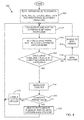
- Fig. 4 is a flowchart 200 of steps followed by processor 25 in operating system 10, according to an embodiment of the present invention.
- operator 16 sets parameters for the histogram of phase shifts, i.e., the number and size of the intervals of the histogram.
- Processor 25 zeroes the histogram by assuming that each of the intervals has a population of zero.
- processor 25 sets a zero-determining counter, the function of which is described below, to zero.
- processor 25 By injecting a current into ablation electrode 32, processor 25 respectively generates a reference waveform and an operational waveform.
- the reference waveform is typically a current vs. time waveform corresponding to reference waveform 41 ( Fig. 2 ), and the operational waveform is typically a voltage vs. time waveform corresponding to a waveform similar to waveforms 43 or 45.
- the processor exits from learning step 202.
- the remaining steps of the flowchart are performed iteratively, while system 10 is being operated.
- the iterations may be performed at a frequency of approximately 10 Hz, although any other convenient iteration frequency may be used.
- the iteration frequency is significantly faster than the frequency of the beating heart, which is approximately 2 Hz.
- a phase shift step 204 the processor calculates the phase shift for the operational waveform by calculating the difference between the reference and operational waveforms.
- the processor adds the calculated phase shift into the appropriate bin of the histogram.
- a first decision step 208 the processor determines if the phase shift calculated in step 206 has been added into the lowest non-zero, i.e., populated, bin of the histogram. For the first iteration of the flowchart, where all bins of the histogram are empty, the return from the decision is positive. For subsequent iterations the return depends on how the histogram is populated at the time of the decision step.
- the lowest non-zero bin of the histogram is the 95° - 100° bin. Consequently, if the calculated phase shift in step 204 is in the interval 95° - 100°, then the return is positive. If the calculated phase shift is in the interval 90° - 95°, or in any of the intervals from 100° to 150°, then the return is negative. It will be understood that if the calculated phase shift is in the interval 90° - 95°, then in the following iteration of the lowest non-zero bin of the histogram is the 90° - 95° bin.
- control continues to a counter setting step 210, wherein the processor sets the zero-determining counter to zero, and from there control passes to an unable-to-zero-sensor step 212.
- step 212 the processor assumes that the force sensor is not in a condition for zeroing, typically because the distal tip of the catheter may be contacting tissue of the heart.
- step 212 includes providing an indication to the operator that the force sensor is not in a condition for zeroing.
- the indication may be visual, such as by providing a notice on screen 29 or changing the color of a button on the screen associated with the force sensor. Alternatively or additionally, the indication may use other operator senses, such as by having an auditory signal. From step 212 control returns to step 204, to initiate another iteration of the flowchart.
- decision step 208 returns positive, i.e., the number or cardinality of the lowest non-zero histogram bin increases, then control proceeds to an increment counter step 214, where the processor increments the zero-determining counter.
- the processor determines if the value of the zero-determining counter is equal to or greater than a preset value.
- a preset value is 4; however, other preset values may be determined without undue experimentation, and all such values are assumed to be within the scope of the present invention.
- step 216 returns positive, control continues to an able-to-zero-sensor step 220, wherein the processor assumes that the force sensor is in a condition for zeroing, typically because the distal tip of the catheter is not contacting tissue of the heart.
- the processor may zero the sensor automatically.
- the processor may provide an indication, such as a visual indication on screen 29, that the force sensor is in a condition for zeroing, and the operator may use this indication to manually zero the sensor.
- the zeroing of the force sensor comprises setting a zero-force point for the force sensor, as a calibration value, according to the force measured by the force sensor after decision step 216 returns positive. If the force sensor is zeroed, then the processor zeros the histogram, reevaluates the intervals for the histogram, and zeroes the zero-determining counter, generally as described above for step 202.
- control returns to step 204 for another iteration of the flowchart.
- step 216 If step 216 returns negative, control continues to an unable-to-zero-sensor step 218, which is substantially as described above for step 212. From step 218 control returns to step 204.
- processor 25 checks if there is a continuous increase in the number, i.e., the cardinality, of the lowest non-zero histogram bin for repeated iterations of the flowchart.
- the processor checks not only that the cardinality is a monotonically increasing function as the flowchart iterates, but that it is a strictly increasing function, i.e., increases in every iteration of the flowchart.
- the cardinality of the continuous increase is measured by the zero-determining counter. If there is a continuous increase, then once the counter reaches a preset value, the force sensor is assumed to be in condition for zeroing.
- the cardinality of the analyzed lowest non-zero histogram bin is not a strictly increasing function. In this case the zero-determining counter is automatically reset to zero and the force sensor is assumed not to be in condition for zeroing.
- processor 25 constructs a histogram similar to that illustrated in Fig. 3 , it will be understood that physical construction of such a histogram is not necessary. Rather, processor 25 may maintain in a memory associated with the processor values equivalent to histogram values, i.e., ordered pairs of (a phase shift interval, a cardinality of the phase shift interval), and the processor may use such ordered pairs to evaluate all the steps of flowchart 200.
Abstract
Description
- This application is related to U.S. Patent Application titled "Determining Non-Contact State for a Catheter," filed on even date with the present application, and which is incorporated herein by reference.
- The present invention relates generally to contact determination, and specifically to determination of absence of contact of a catheter with body tissue.
- In an ablation procedure on target tissue, such as the myocardium, verification of physical electrode contact with the target tissue, as well as measurement of the force or pressure of the contact, are important for controlling the delivery of ablation energy to the tissue. Attempts in the art to verify electrode contact with the tissue, and to accurately measure the contact force, have been extensive, and various techniques have been suggested. For example,
U.S. Patent No. 6,695,808 , which is incorporated herein by reference, describes apparatus for treating a selected patient tissue or organ region. A probe has a contact surface that may be urged against the region, thereby creating contact pressure. A pressure transducer measures the contact pressure. This arrangement is said to meet the needs of procedures in which a medical instrument must be placed in firm but not excessive contact with an anatomical surface, by providing information to the user of the instrument that is indicative of the existence and magnitude of the contact force. - As another example,
U.S. Patent No. 6,241,724 , which is incorporated herein by reference, describes methods for creating lesions in body tissue using segmented electrode assemblies. In one embodiment, an electrode assembly on a catheter carries pressure transducers, which sense contact with tissue and convey signals to a pressure contact module. The module identifies the electrode elements that are associated with the pressure transducer signals and directs an energy generator to convey RF energy to these elements, and not to other elements that are in contact only with blood. - A further example is presented in
U.S. Patent No. 6,915,149 , which is incorporated herein by reference. This patent describes a method for mapping a heart using a catheter having a tip electrode for measuring local electrical activity. In order to avoid artifacts that may arise from poor tip contact with the tissue, the contact pressure between the tip and the tissue is measured using a pressure sensor to ensure stable contact. -
U.S. Patent Application Publication 2007/0100332 , which is incorporated herein by reference, describes systems and methods for assessing electrode-tissue contact for tissue ablation. An electro-mechanical sensor within the catheter shaft generates electrical signals corresponding to the amount of movement of the electrode within a distal portion of the catheter shaft. An output device receives the electrical signals for assessing a level of contact between the electrode and a tissue. -
U.S. Patent No. 7,306,593, issued to Keidar et al. , which is incorporated herein by reference, describes a method for ablating tissue in an organ by contacting a probe inside the body with the tissue to be ablated, and measuring one or more local parameters at the position using the probe prior to ablating the tissue. A map of the organ is displayed, showing, based on the one or more local parameters, a predicted extent of ablation of the tissue to be achieved for a given dosage of energy applied at the position using the probe. The given dosage of energy is applied to ablate the tissue using the probe, and an actual extent of the ablation at the position is measured using the probe subsequent to ablating the tissue. The measured actual extent of the ablation is displayed on the map for comparison with the predicted extent. - Impedance-based methods for assessing catheter-tissue contact that are known in the art typically rely on measurement of the magnitude of the impedance between an electrode on the catheter and a body-surface electrode. When the magnitude is below some threshold, the electrode is considered to be in contact with the tissue. This sort of binary contact indication may be unreliable, however, and is sensitive to changes in the impedance between the body-surface electrode and the skin.
-
U.S. Patent Application Publication Nos. 2008/0288038 and2008/0275465, both by Saurav et al. , which are incorporated herein by reference, describe an electrode catheter system having an electrode adapted to apply electric energy. A measurement circuit adapted to measure impedance may be implemented between the electrode and ground as the electrode approaches a target tissue. A processor or processing units may be implemented to determine a contact condition for the target tissue based at least in part on reactance of the impedance measured by the measurement circuit. In another embodiment, the contact condition may be based on the phase angle of the impedance. - Documents incorporated by reference in the present patent application are to be considered an integral part of the application except that to the extent any terms are defined in these incorporated documents in a manner that conflicts with the definitions made explicitly or implicitly in the present specification, only the definitions in the present specification should be considered.
- An embodiment of the present invention provides a method, including:
- injecting a current between an electrode of a catheter and tissue in proximity to the catheter, the catheter having a force sensor configured to measure a force between the catheter and the tissue;
- measuring a succession of phase shifts of the current relative to a fixed reference;
- verifying that a cardinality of the measured phase shifts falling below a predetermined threshold increases over a predetermined time period; and
- calibrating a zero-force point for the force sensor according to the force measured by the force sensor during the predetermined time period.
- Typically, the cardinality is a strictly increasing function over the predetermined time period.
- In a disclosed embodiment the succession of phase shifts includes a preset number of the measured phase shifts.
- In a further disclosed embodiment the measured phase shifts falling below a predetermined threshold include phase shifts within a preset interval of possible values of the phase shifts. The method may further include, prior to verifying the cardinality of the measured phase shifts, determining values for the preset interval in a learning phase of the method.
- In a yet further disclosed embodiment the method includes determining the fixed reference from a current versus time waveform generated by the current. Typically, measuring the succession of phase shifts includes comparing the current versus time waveform with a voltage versus time waveform generated by the current.
- In an alternative embodiment calibrating the zero-force point includes automatically setting the zero-force point as the force measured by the force sensor. Alternatively, calibrating the zero-force point includes manually setting the zero-force point as the force measured by the force sensor.
- There is further provided, according to an embodiment of the present invention apparatus, including:
- a catheter having an electrode and a force sensor configured to measure a force between the catheter and tissue in proximity to the catheter; and
- a processor configured to:
- inject a current between the electrode and the tissue,
- measure a succession of phase shifts of the current relative to a fixed reference,
- verify that a cardinality of the measured phase shifts falling below a predetermined threshold increases over a predetermined time period, and
- calibrate a zero-force point for the force sensor according to the force measured by the force sensor during the predetermined time period.
- The present disclosure will be more fully understood from the following detailed description of the embodiments thereof, taken together with the drawings, in which:
-
-
Fig. 1 is a pictorial illustration of a catheter system for performing ablative procedures on a heart of a living subject, according to an embodiment of the invention; -
Fig. 2 is a composite drawing illustrating phase relationships of a current passing through an ablation electrode, according to an embodiment of the invention; -
Fig. 3 is a schematic histogram generated by a processor, while the processor operates the system ofFig. 1 , according to an embodiment of the present invention; and -
Fig. 4 is a flowchart of steps followed by the processor in operating the system ofFig. 1 , according to an embodiment of the present invention. - An embodiment of the present invention provides a simple, quick, and accurate method for determining if a force sensor of a catheter is in condition for zeroing. In other words, the method detects, with a probability of being correct of at least 99%, if a distal tip of the catheter, wherein the force sensor is located, is not in contact with body tissue, such as wall tissue of a heart chamber. The method may advantageously be used during an ablation procedure on the heart.
- The method injects current between an electrode, herein also termed the ablation electrode, at the distal tip of the catheter and the body tissue. The ablation electrode may or may not be in contact with the tissue. Phase shifts of the injected current are measured relative to a fixed reference, the phase shifts varying depending upon whether or not the ablation electrode contacts the tissue. Typically, the phase shifts are measured from differences between a current waveform and a voltage waveform of the injected current.
- The phase shifts are measured in an iterative manner, typically at a frequency of approximately 10 Hz, and the measurements are used to populate bins of a histogram of phase shifts. If there is a consistent increase, at every iteration, in the number of phase shift measurements below a predetermined phase shift threshold, typically in the lowest non-zero bin of the histogram, and if the consistent increase continues for more than a preset number of iterations, corresponding to a predetermined time period, then the force sensor is assumed to be out of contact with the tissue. In this case the force sensor may be calibrated, by assuming that the force reading of the force sensor is a zero-force point for the sensor.
- The inventors have found that not only does the method detect, with an extremely high probability of being correct, if the sensor is in condition for zeroing, but also that the waiting time before such detection is very short. In one embodiment the preset number of iterations required for a consistent increase is four, so that since each iteration is of the order of tenths of seconds, the predetermined time period, i.e., the waiting time, is less than one second.
- In the following description, like elements in the drawings are identified by like numerals, and the like elements are differentiated as necessary by appending a letter to the identifying numeral.
- Reference is now made to
Fig. 1 , which is a pictorial illustration of acatheter system 10 for performing ablative procedures on aheart 12 of aliving subject 13, according to an embodiment of the invention. The system comprises acatheter 14, which is percutaneously inserted by anoperator 16 through the patient's vascular system into a chamber or vascular structure of the heart. The operator, who is typically a physician, brings the catheter'sdistal tip 18 into contact with the heart wall at an ablation target site. Optionally, electrical activation maps may then be prepared, according to the methods disclosed inU.S. Patent Nos. 6,226,542 , and6,301,496 , and in commonly assignedU.S. Patent No. 6,892,091 , whose disclosures are herein incorporated by reference. One commercial product embodying elements ofsystem 10 is available as theCARTO ® 3 System, available from Biosense Webster, Inc., 3333 Diamond Canyon Road, Diamond Bar, CA 91765. - Areas determined to be abnormal, for example by evaluation of the electrical activation maps, can be ablated by application of thermal energy, e.g., by passage of radiofrequency electrical current through wires in the catheter to one or more electrodes at
distal tip 18, which apply the radiofrequency energy to the myocardium. The energy is absorbed in the tissue, heating it to a point (typically about 50°C) at which it permanently loses its electrical excitability. This procedure creates non-conducting lesions in the cardiac tissue, which disrupt the abnormal electrical pathway causing the arrhythmia. The principles of the invention can be applied to different heart chambers to treat many different cardiac arrhythmias. -
Catheter 14 typically comprises ahandle 20, having suitable controls on the handle to enableoperator 16 to steer, position and orient the distal end of the catheter as desired for the ablation. To aid the operator, the distal portion ofcatheter 14 may contain position sensors (not shown) that provide signals to apositioning processor 22, located in aconsole 24. - Ablation energy signals and other electrical signals can be conveyed to and from
heart 12 through anelectrode 32 located atdistal tip 18 via acable 34 to console 24.Electrode 32 may also be referred to herein as the ablation electrode. There may be other electrodes (not shown) located at the distal tip that are used for ablation. Pacing signals and other control signals may be conveyed from the console throughcable 34 andelectrode 32, or via the other electrodes at the distal tip, to the heart; these signals may be conveyed in parallel with any ablation energy signals, typically by using frequency multiplexing for the different signals. - Factors affecting the ablation generated by the ablation energy input to the tissue being ablated comprise, inter alia, the force applied to the tissue during the ablation process. In order to measure the force, the distal end of
catheter 14 comprises aforce sensor 36. Force or pressure sensors that are suitable for use in a catheter are well known in the art. For example,U.S. Patent Application Publications 2007/0100332 and2009/0093806 , whose disclosures are incorporated herein by reference, describe methods of sensing contact pressure between the distal tip of a catheter and tissue in a body cavity using a force or pressure sensor embedded in the catheter. However,force sensor 36 may comprise any other force or pressure sensor known in the art. -
Wire connections 35 link the console withbody surface electrodes 30 and other components of a positioning sub-system.Electrode 32 andbody surface electrodes 30 may be used to measure tissue impedance at the ablation site as taught inU.S. Patent No. 7,536,218, issued to Govari et al. , which is herein incorporated by reference. A temperature sensor (not shown), typically a thermocouple or thermistor, may be mounted on ornear electrode 32. - Positioning
processor 22 is an element of a positioning subsystem (of system 10) which measures location and orientation coordinates ofcatheter 14. - In one embodiment, the positioning subsystem comprises a magnetic position tracking arrangement that determines the position and orientation of
catheter 14 by generating magnetic fields in a predefined working volume in the vicinity of the catheter, using field generating coils 28. These fields are sensed at the catheter and the sensed fields are used to determine positions and orientation coordinates for the catheter. Alternatively or additionally, the location ofcatheter 14 may also be determined using impedance measurements, as taught, for example inU.S. Patent Application Publication No. 2007/0060832 , which is herein incorporated by reference. The positioning subsystem may be enhanced by position measurements using the impedance measurements described in the above-notedU.S. Patent No. 7,536,218 . - As noted above,
catheter 14 is coupled to console 24, which enablesoperator 16 to observe and regulate the functions of the catheter.Console 24 includes aprocessor 25, preferably a computer with appropriate signal processing circuits, which operatessystem 10.Processor 25 is coupled to drive amonitor 29. The signal processing circuits typically receive, amplify, filter and digitize signals fromcatheter 14, including signals generated by the above-noted sensors and a plurality of location sensing electrodes (not shown) located distally in the catheter. The digitized signals are received and used by the console and the positioning subsystem to compute the position and orientation ofcatheter 14 and to analyze the electrical signals from the electrodes. -
Fig. 2 is a composite drawing illustrating phase relationships of a current passing throughablation electrode 32, according to an embodiment of the invention. The current is typically separate from the ablation current passing through the ablation electrode, and since the current is used to ascertain if contact of the ablation electrode with the heart wall does or does not occur the current is also herein termed the contact determining current. The contact determining current passing throughablation electrode 32 is an alternating current, having a phase shift which, as is described below, may be measured by comparing a current waveform with a voltage waveform generated by the current. The contact determining current throughablation electrode 32 is typically also used to make impedance measurements, so as to determine a location of the ablation electrode, as is described in above-referencedU.S. Patent Application Publication No. 2007/0060832 andU.S. Patent No. 7,536,218 . - As is described in more detail below, embodiments of the present invention measure changes in the phase shift of the contact determining current through
ablation electrode 32 in order to determine whether or not there is contact between the ablation electrode andwall tissue 37 ofheart 12. - Waveforms at the right side of
Fig. 2 include, from top to bottom, a current (I) vs. time (t)waveform 41 of the contact determining current throughelectrode 32, a pre-contact voltage (V) vs.t waveform 43 for the current, taken whenablation electrode 32 is out of contact withwall 37, and a contact voltage (V) vs.t waveform 45 for the current, taken when the ablation electrode is in mechanical contact withwall 37. - The phase of current
vs. time waveform 41 does not change substantially as the ablation electrode makes contact with the tissue.Waveform 41 may therefore be used as a fixed reference waveform for measuring the phase shift of the current passing through the ablation electrode or another tip electrode (not shown). It should be noted that ablation energy may be provided to the tissue while concurrently monitoring the phase shift. It is not necessary to interlace the two operations of providing ablation energy and monitoring the phase shift. - Phase shifts are indicated by displacement of
vertical lines pre-contact waveform 43 and thecontact waveform 45. The phase shifts are measured with respect to the corresponding maximum of the reference waveform, indicated by avertical line 53. - A change in phase shift occurs when
ablation electrode 32 is brought into contact withwall 37. Furthermore, the phase shift increases on contact withwall 37, as is illustrated bywaveforms force sensor 36 may be zeroed. - Typically, during a medical procedure involving the measurement of force by
sensor 36, the output of the sensor drifts, even though the force on the sensor may be constant. The drift is typically caused by changes in parameters of physical elements associated with the sensor, such as gain changes of amplifiers and/or dimensional changes of parts of the sensor. The drift may be compensated for by zeroing the sensor, but the zeroing should only be performed when there is no contact between the distal tip of the catheter andwall 37. Embodiments of the present invention providesystem 10, and/oroperator 16 of the system, with an indication that there is no contact between the catheter distal tip and any solid object, such aswall 37. -
Fig. 3 is a schematic histogram generated byprocessor 25, while the processor operatessystem 10, according to an embodiment of the present invention. During operation ofsystem 10,processor 25 evaluates the phase shift experienced byablation electrode 32. The evaluation is performed on a repetitive basis, typically with a frequency at least equal to 10 Hz. -
Processor 25 incorporates the evaluated phase shifts into a histogram of phase shifts. At the initial setup ofsystem 10, the number of the bins of the histogram is typically preset. In one embodiment, illustrated inFig. 3 , there are 12 equal bins. The intervals for the bins are typically set dynamically, as is explained below.Fig. 3 illustrates the histogram having bins of 5° phase shift intervals, the phase shift of the histogram varying between a minimum of 90° to a maximum of 150°. - As the processor incorporates evaluated phase shifts into the histogram, it analyzes the histogram to determine if
force sensor 32 is in a condition for zeroing. The method followed by the processor in building and analyzing the histogram is described with reference to the flowchart ofFig. 4 . -
Fig. 4 is aflowchart 200 of steps followed byprocessor 25 inoperating system 10, according to an embodiment of the present invention. In an initiallearning phase step 202,operator 16 sets parameters for the histogram of phase shifts, i.e., the number and size of the intervals of the histogram.Processor 25 zeroes the histogram by assuming that each of the intervals has a population of zero. In addition,processor 25 sets a zero-determining counter, the function of which is described below, to zero. - By injecting a current into
ablation electrode 32,processor 25 respectively generates a reference waveform and an operational waveform. The reference waveform is typically a current vs. time waveform corresponding to reference waveform 41 (Fig. 2 ), and the operational waveform is typically a voltage vs. time waveform corresponding to a waveform similar towaveforms - During learning
phase step 202 the processor calculates phase shifts for the injected current, and stores the phase shifts in a buffer. Typically, a number of phase shifts stored is approximately 100, although any other number may be used. Using the minimum and maximum values of the stored phase shifts, the processor calculates intervals for the histogram bins. For example, if the phase shifts vary between a minimum of 70° and a maximum of 100°, then the 12 bins of the histogram are set to cover the range of 70° to 100°, and each bin interval is set to be
- Once the intervals of the bins have been set, the processor exits from learning
step 202. - The remaining steps of the flowchart are performed iteratively, while
system 10 is being operated. The iterations may be performed at a frequency of approximately 10 Hz, although any other convenient iteration frequency may be used. Typically, the iteration frequency is significantly faster than the frequency of the beating heart, which is approximately 2 Hz. - For each iteration of the flowchart, in a
phase shift step 204, the processor calculates the phase shift for the operational waveform by calculating the difference between the reference and operational waveforms. - In a
population step 206, the processor adds the calculated phase shift into the appropriate bin of the histogram. - In a
first decision step 208, the processor determines if the phase shift calculated instep 206 has been added into the lowest non-zero, i.e., populated, bin of the histogram. For the first iteration of the flowchart, where all bins of the histogram are empty, the return from the decision is positive. For subsequent iterations the return depends on how the histogram is populated at the time of the decision step. - For example, if the histogram at the time of
decision step 208 is as shown inFig. 3 , then the lowest non-zero bin of the histogram is the 95° - 100° bin. Consequently, if the calculated phase shift instep 204 is in theinterval 95° - 100°, then the return is positive. If the calculated phase shift is in theinterval 90° - 95°, or in any of the intervals from 100° to 150°, then the return is negative. It will be understood that if the calculated phase shift is in theinterval 90° - 95°, then in the following iteration of the lowest non-zero bin of the histogram is the 90° - 95° bin. - If the decision returns negative, then control continues to a
counter setting step 210, wherein the processor sets the zero-determining counter to zero, and from there control passes to an unable-to-zero-sensor step 212. - In
step 212 the processor assumes that the force sensor is not in a condition for zeroing, typically because the distal tip of the catheter may be contacting tissue of the heart. In some embodiments, where zeroing of the force sensor may be performed byoperator 16 manually,step 212 includes providing an indication to the operator that the force sensor is not in a condition for zeroing. The indication may be visual, such as by providing a notice onscreen 29 or changing the color of a button on the screen associated with the force sensor. Alternatively or additionally, the indication may use other operator senses, such as by having an auditory signal. Fromstep 212 control returns to step 204, to initiate another iteration of the flowchart. - If
decision step 208 returns positive, i.e., the number or cardinality of the lowest non-zero histogram bin increases, then control proceeds to anincrement counter step 214, where the processor increments the zero-determining counter. - In a
second decision step 216, the processor determines if the value of the zero-determining counter is equal to or greater than a preset value. In one embodiment the preset value is 4; however, other preset values may be determined without undue experimentation, and all such values are assumed to be within the scope of the present invention. - If
step 216 returns positive, control continues to an able-to-zero-sensor step 220, wherein the processor assumes that the force sensor is in a condition for zeroing, typically because the distal tip of the catheter is not contacting tissue of the heart. At this step the processor may zero the sensor automatically. Alternatively, the processor may provide an indication, such as a visual indication onscreen 29, that the force sensor is in a condition for zeroing, and the operator may use this indication to manually zero the sensor. The zeroing of the force sensor comprises setting a zero-force point for the force sensor, as a calibration value, according to the force measured by the force sensor afterdecision step 216 returns positive. If the force sensor is zeroed, then the processor zeros the histogram, reevaluates the intervals for the histogram, and zeroes the zero-determining counter, generally as described above forstep 202. - From
step 220, control returns to step 204 for another iteration of the flowchart. - If
step 216 returns negative, control continues to an unable-to-zero-sensor step 218, which is substantially as described above forstep 212. Fromstep 218 control returns to step 204. - Consideration of
flowchart 200 shows thatprocessor 25 checks if there is a continuous increase in the number, i.e., the cardinality, of the lowest non-zero histogram bin for repeated iterations of the flowchart. In other words, the processor checks not only that the cardinality is a monotonically increasing function as the flowchart iterates, but that it is a strictly increasing function, i.e., increases in every iteration of the flowchart. The cardinality of the continuous increase is measured by the zero-determining counter. If there is a continuous increase, then once the counter reaches a preset value, the force sensor is assumed to be in condition for zeroing. - If there is no such continuous increase, i.e., if one of the iterations of the flowchart causes an increase in a non-lowest histogram bin, or creates a new lowest non-zero histogram bin, then the cardinality of the analyzed lowest non-zero histogram bin is not a strictly increasing function. In this case the zero-determining counter is automatically reset to zero and the force sensor is assumed not to be in condition for zeroing.
- While the description above has assumed that
processor 25 constructs a histogram similar to that illustrated inFig. 3 , it will be understood that physical construction of such a histogram is not necessary. Rather,processor 25 may maintain in a memory associated with the processor values equivalent to histogram values, i.e., ordered pairs of (a phase shift interval, a cardinality of the phase shift interval), and the processor may use such ordered pairs to evaluate all the steps offlowchart 200. - It will thus be appreciated that the embodiments described above are cited by way of example, and that the present invention is not limited to what has been particularly shown and described hereinabove. Rather, the scope of the present invention includes both combinations and subcombinations of the various features described hereinabove, as well as variations and modifications thereof which would occur to persons skilled in the art upon reading the foregoing description and which are not disclosed in the prior art.
Claims (14)
- A method, comprising:injecting a current between an electrode of a catheter and tissue in proximity to the catheter, the catheter comprising a force sensor configured to measure a force between the catheter and the tissue;measuring a succession of phase shifts of the current relative to a fixed reference;verifying that a cardinality of the measured phase shifts falling below a predetermined threshold increases over a predetermined time period; andcalibrating a zero-force point for the force sensor according to the force measured by the force sensor during the predetermined time period.
- The method according to claim 1, and comprising determining the fixed reference from a current versus time waveform generated by the current.
- The method according to claim 2, wherein measuring the succession of phase shifts comprises comparing the current versus time waveform with a voltage versus time waveform generated by the current.
- The method according to claim 1, wherein calibrating the zero-force point comprises automatically setting the zero-force point as the force measured by the force sensor.
- The method according to claim 1, wherein calibrating the zero-force point comprises manually setting the zero-force point as the force measured by the force sensor.
- Apparatus, comprising:a catheter comprising an electrode and a force sensor configured to measure a force between the catheter and tissue in proximity to the catheter; anda processor configured to:inject a current between the electrode and the tissue,measure a succession of phase shifts of the current relative to a fixed reference,verify that a cardinality of the measured phase shifts falling below a predetermined threshold increases over a predetermined time period, andcalibrate a zero-force point for the force sensor according to the force measured by the force sensor during the predetermined time period.
- The method according to claim 1 or the apparatus according to claim 6, wherein the cardinality is a strictly increasing function over the predetermined time period.
- The method according to claim 1 or the apparatus according to claim 6, wherein the succession of phase shifts comprises a preset number of the measured phase shifts.
- The method according to claim 1 or the apparatus according to claim 6, wherein the measured phase shifts falling below a predetermined threshold comprise phase shifts within a preset interval of possible values of the phase shifts.
- The method or apparatus according to claim 9, and comprising, prior to verifying the cardinality of the measured phase shifts, determining values for the preset interval in a learning phase of the method.
- The apparatus according to claim 6, wherein the processor is configured to determine the fixed reference from a current versus time waveform generated by the current.
- The apparatus according to claim 11, wherein measuring the succession of phase shifts comprises comparing the current versus time waveform with a voltage versus time waveform generated by the current.
- The apparatus according to claim 6, wherein calibrating the zero-force point comprises the processor automatically setting the zero-force point as the force measured by the force sensor.
- The apparatus according to claim 6, wherein calibrating the zero-force point comprises an operator of the apparatus manually setting the zero-force point as the force measured by the force sensor.
Applications Claiming Priority (1)
| Application Number | Priority Date | Filing Date | Title |
|---|---|---|---|
| US14/010,679 US9974608B2 (en) | 2013-08-27 | 2013-08-27 | Determining absence of contact for a catheter |
Publications (2)
| Publication Number | Publication Date |
|---|---|
| EP2842507A1 true EP2842507A1 (en) | 2015-03-04 |
| EP2842507B1 EP2842507B1 (en) | 2019-05-29 |
Family
ID=51392153
Family Applications (1)
| Application Number | Title | Priority Date | Filing Date |
|---|---|---|---|
| EP14182246.0A Active EP2842507B1 (en) | 2013-08-27 | 2014-08-26 | Determining absence of contact for a catheter |
Country Status (8)
| Country | Link |
|---|---|
| US (1) | US9974608B2 (en) |
| EP (1) | EP2842507B1 (en) |
| JP (1) | JP6448952B2 (en) |
| CN (1) | CN104414653B (en) |
| AU (1) | AU2014215987B2 (en) |
| CA (1) | CA2859819A1 (en) |
| ES (1) | ES2734002T3 (en) |
| IL (1) | IL234037B (en) |
Cited By (1)
| Publication number | Priority date | Publication date | Assignee | Title |
|---|---|---|---|---|
| EP3964152A1 (en) * | 2020-09-04 | 2022-03-09 | Erbe Elektromedizin GmbH | Tissue treatment device and method for detecting electrode head / tissue contact |
Families Citing this family (8)
| Publication number | Priority date | Publication date | Assignee | Title |
|---|---|---|---|---|
| CN104825234A (en) * | 2015-05-15 | 2015-08-12 | 四川锦江电子科技有限公司 | Detecting method and device for attaching of multi-electrode ablation catheter to heart tissue |
| CN108430365B (en) * | 2015-12-20 | 2021-07-02 | 波士顿科学医学有限公司 | Miniature inductive position sensor |
| EP3407815B1 (en) | 2016-01-29 | 2023-06-21 | Boston Scientific Scimed Inc. | Force sensing catheter with impedance-guided orientation |
| US11369431B2 (en) | 2016-06-11 | 2022-06-28 | Boston Scientific Scimed Inc. | Inductive double flat coil displacement sensor |
| CN110809448B (en) * | 2017-04-27 | 2022-11-25 | Epix疗法公司 | Determining properties of contact between catheter tip and tissue |
| US11484359B2 (en) * | 2017-10-31 | 2022-11-01 | Biosense Webster (Israel) Ltd. | Method and system for gap detection in ablation lines |
| US10827978B2 (en) * | 2017-11-22 | 2020-11-10 | Boston Scientific Scimed Inc. | Impedance-based far-field subtraction of waveform using non-tissue contacting electrodes |
| US20200046420A1 (en) | 2018-08-08 | 2020-02-13 | Biosense Webster (Israel) Ltd. | Contact force sensor comprising tuned amplifiers |
Citations (16)
| Publication number | Priority date | Publication date | Assignee | Title |
|---|---|---|---|---|
| US6226542B1 (en) | 1998-07-24 | 2001-05-01 | Biosense, Inc. | Three-dimensional reconstruction of intrabody organs |
| US6241724B1 (en) | 1993-10-19 | 2001-06-05 | Ep Technologies, Inc. | Systems and methods for creating lesions in body tissue using segmented electrode assemblies |
| US6301496B1 (en) | 1998-07-24 | 2001-10-09 | Biosense, Inc. | Vector mapping of three-dimensionally reconstructed intrabody organs and method of display |
| US6695808B2 (en) | 2000-03-23 | 2004-02-24 | Scimed Life Systems, Inc. | Pressure sensor for therapeutic delivery device and method |
| US6892091B1 (en) | 2000-02-18 | 2005-05-10 | Biosense, Inc. | Catheter, method and apparatus for generating an electrical map of a chamber of the heart |
| US6915149B2 (en) | 1996-01-08 | 2005-07-05 | Biosense, Inc. | Method of pacing a heart using implantable device |
| US20070060832A1 (en) | 2005-08-26 | 2007-03-15 | Michael Levin | Detection of skin impedance |
| US20070100332A1 (en) | 2005-10-27 | 2007-05-03 | St. Jude Medical, Atrial Fibrillation Division, Inc. | Systems and methods for electrode contact assessment |
| US7306593B2 (en) | 2002-10-21 | 2007-12-11 | Biosense, Inc. | Prediction and assessment of ablation of cardiac tissue |
| US20080275465A1 (en) | 2005-12-06 | 2008-11-06 | Saurav Paul | Design of Handle Set for Ablation Catheter with Indicators of Catheter and Tissue Parameters |
| US20090093806A1 (en) | 2007-10-08 | 2009-04-09 | Assaf Govari | Catheter with pressure sensing |
| US7536218B2 (en) | 2005-07-15 | 2009-05-19 | Biosense Webster, Inc. | Hybrid magnetic-based and impedance-based position sensing |
| WO2009065140A1 (en) * | 2007-11-16 | 2009-05-22 | St. Jude Medical, Atrial Fibrillation Division, Inc. | Device and method for real-time lesion estimation during ablation |
| EP2397099A1 (en) * | 2010-06-16 | 2011-12-21 | Biosense Webster (Israel), Ltd | Optical contact sensing in medical probes |
| EP2438881A1 (en) * | 2010-10-07 | 2012-04-11 | Biosense Webster (Israel), Ltd. | Calibration system for a force-sensing catheter |
| EP2574278A2 (en) * | 2011-09-30 | 2013-04-03 | Biosense Webster (Israel), Ltd. | In-vivo calibration of contact force-sensing catheters |
Family Cites Families (10)
| Publication number | Priority date | Publication date | Assignee | Title |
|---|---|---|---|---|
| US20030212393A1 (en) * | 1996-01-05 | 2003-11-13 | Knowlton Edward W. | Handpiece with RF electrode and non-volatile memory |
| US7192427B2 (en) | 2002-02-19 | 2007-03-20 | Afx, Inc. | Apparatus and method for assessing transmurality of a tissue ablation |
| EP1623246A1 (en) * | 2003-04-14 | 2006-02-08 | Koninklijke Philips Electronics N.V. | Magnetic resonance imaging with histogram-based phase correction |
| US20070070832A1 (en) | 2005-09-29 | 2007-03-29 | Jim Paikattu | Secure removable media drive |
| US20080312521A1 (en) * | 2007-06-14 | 2008-12-18 | Solomon Edward G | System and method for determining electrode-tissue contact using phase difference |
| CN104605928B (en) * | 2009-05-08 | 2018-01-05 | 圣犹达医疗用品国际控股有限公司 | System for controlling lesion size in the ablation based on conduit |
| US8374670B2 (en) * | 2010-01-22 | 2013-02-12 | Biosense Webster, Inc. | Catheter having a force sensing distal tip |
| WO2012047626A1 (en) * | 2010-09-27 | 2012-04-12 | University Of Pittsburgh - Of The Commonwealth System Of Higher Education | Portable haptic force magnifier |
| US8979772B2 (en) * | 2010-11-03 | 2015-03-17 | Biosense Webster (Israel), Ltd. | Zero-drift detection and correction in contact force measurements |
| US9687289B2 (en) * | 2012-01-04 | 2017-06-27 | Biosense Webster (Israel) Ltd. | Contact assessment based on phase measurement |
-
2013
- 2013-08-27 US US14/010,679 patent/US9974608B2/en active Active
-
2014
- 2014-08-10 IL IL234037A patent/IL234037B/en active IP Right Grant
- 2014-08-19 CA CA2859819A patent/CA2859819A1/en not_active Abandoned
- 2014-08-21 AU AU2014215987A patent/AU2014215987B2/en active Active
- 2014-08-26 EP EP14182246.0A patent/EP2842507B1/en active Active
- 2014-08-26 JP JP2014171241A patent/JP6448952B2/en active Active
- 2014-08-26 ES ES14182246T patent/ES2734002T3/en active Active
- 2014-08-27 CN CN201410429442.8A patent/CN104414653B/en active Active
Patent Citations (17)
| Publication number | Priority date | Publication date | Assignee | Title |
|---|---|---|---|---|
| US6241724B1 (en) | 1993-10-19 | 2001-06-05 | Ep Technologies, Inc. | Systems and methods for creating lesions in body tissue using segmented electrode assemblies |
| US6915149B2 (en) | 1996-01-08 | 2005-07-05 | Biosense, Inc. | Method of pacing a heart using implantable device |
| US6226542B1 (en) | 1998-07-24 | 2001-05-01 | Biosense, Inc. | Three-dimensional reconstruction of intrabody organs |
| US6301496B1 (en) | 1998-07-24 | 2001-10-09 | Biosense, Inc. | Vector mapping of three-dimensionally reconstructed intrabody organs and method of display |
| US6892091B1 (en) | 2000-02-18 | 2005-05-10 | Biosense, Inc. | Catheter, method and apparatus for generating an electrical map of a chamber of the heart |
| US6695808B2 (en) | 2000-03-23 | 2004-02-24 | Scimed Life Systems, Inc. | Pressure sensor for therapeutic delivery device and method |
| US7306593B2 (en) | 2002-10-21 | 2007-12-11 | Biosense, Inc. | Prediction and assessment of ablation of cardiac tissue |
| US7536218B2 (en) | 2005-07-15 | 2009-05-19 | Biosense Webster, Inc. | Hybrid magnetic-based and impedance-based position sensing |
| US20070060832A1 (en) | 2005-08-26 | 2007-03-15 | Michael Levin | Detection of skin impedance |
| US20070100332A1 (en) | 2005-10-27 | 2007-05-03 | St. Jude Medical, Atrial Fibrillation Division, Inc. | Systems and methods for electrode contact assessment |
| US20080275465A1 (en) | 2005-12-06 | 2008-11-06 | Saurav Paul | Design of Handle Set for Ablation Catheter with Indicators of Catheter and Tissue Parameters |
| US20080288038A1 (en) | 2005-12-06 | 2008-11-20 | Saurav Paul | Method for Displaying Catheter Electrode-Tissue Contact in Electro-Anatomic Mapping and Navigation System |
| US20090093806A1 (en) | 2007-10-08 | 2009-04-09 | Assaf Govari | Catheter with pressure sensing |
| WO2009065140A1 (en) * | 2007-11-16 | 2009-05-22 | St. Jude Medical, Atrial Fibrillation Division, Inc. | Device and method for real-time lesion estimation during ablation |
| EP2397099A1 (en) * | 2010-06-16 | 2011-12-21 | Biosense Webster (Israel), Ltd | Optical contact sensing in medical probes |
| EP2438881A1 (en) * | 2010-10-07 | 2012-04-11 | Biosense Webster (Israel), Ltd. | Calibration system for a force-sensing catheter |
| EP2574278A2 (en) * | 2011-09-30 | 2013-04-03 | Biosense Webster (Israel), Ltd. | In-vivo calibration of contact force-sensing catheters |
Cited By (1)
| Publication number | Priority date | Publication date | Assignee | Title |
|---|---|---|---|---|
| EP3964152A1 (en) * | 2020-09-04 | 2022-03-09 | Erbe Elektromedizin GmbH | Tissue treatment device and method for detecting electrode head / tissue contact |
Also Published As
| Publication number | Publication date |
|---|---|
| US9974608B2 (en) | 2018-05-22 |
| IL234037B (en) | 2019-05-30 |
| IL234037A0 (en) | 2014-11-30 |
| JP6448952B2 (en) | 2019-01-09 |
| AU2014215987B2 (en) | 2019-05-30 |
| CN104414653A (en) | 2015-03-18 |
| US20150066021A1 (en) | 2015-03-05 |
| JP2015043980A (en) | 2015-03-12 |
| CA2859819A1 (en) | 2015-02-27 |
| ES2734002T3 (en) | 2019-12-03 |
| CN104414653B (en) | 2019-07-30 |
| EP2842507B1 (en) | 2019-05-29 |
| AU2014215987A1 (en) | 2015-03-19 |
Similar Documents
| Publication | Publication Date | Title |
|---|---|---|
| US9974608B2 (en) | Determining absence of contact for a catheter | |
| US10182860B2 (en) | Assessment of electrode coupling for tissue ablation | |
| US8267926B2 (en) | Assessment of electrode coupling for tissue ablation | |
| US8317783B2 (en) | Assessment of electrode coupling for tissue ablation | |
| US9173586B2 (en) | System and method for assessing coupling between an electrode and tissue | |
| EP2101642B1 (en) | Contact sensor and sheath exit sensor | |
| EP2842508B1 (en) | Determining non-contact state for a catheter | |
| AU2019204909B2 (en) | Assistive manual zeroing visualization |
Legal Events
| Date | Code | Title | Description |
|---|---|---|---|
| 17P | Request for examination filed |
Effective date: 20140826 |
|
| AK | Designated contracting states |
Kind code of ref document: A1 Designated state(s): AL AT BE BG CH CY CZ DE DK EE ES FI FR GB GR HR HU IE IS IT LI LT LU LV MC MK MT NL NO PL PT RO RS SE SI SK SM TR |
|
| AX | Request for extension of the european patent |
Extension state: BA ME |
|
| PUAI | Public reference made under article 153(3) epc to a published international application that has entered the european phase |
Free format text: ORIGINAL CODE: 0009012 |
|
| R17P | Request for examination filed (corrected) |
Effective date: 20150825 |
|
| RBV | Designated contracting states (corrected) |
Designated state(s): AL AT BE BG CH CY CZ DE DK EE ES FI FR GB GR HR HU IE IS IT LI LT LU LV MC MK MT NL NO PL PT RO RS SE SI SK SM TR |
|
| GRAP | Despatch of communication of intention to grant a patent |
Free format text: ORIGINAL CODE: EPIDOSNIGR1 |
|
| STAA | Information on the status of an ep patent application or granted ep patent |
Free format text: STATUS: GRANT OF PATENT IS INTENDED |
|
| RIC1 | Information provided on ipc code assigned before grant |
Ipc: A61B 90/00 20150304ALI20181009BHEP Ipc: A61B 5/053 20060101ALN20181009BHEP Ipc: A61B 18/14 20060101AFI20181009BHEP Ipc: A61B 18/00 20060101ALN20181009BHEP Ipc: A61B 17/00 20060101ALN20181009BHEP Ipc: A61B 5/00 20060101ALI20181009BHEP |
|
| RIC1 | Information provided on ipc code assigned before grant |
Ipc: A61B 18/00 20060101ALN20181019BHEP Ipc: A61B 17/00 20060101ALN20181019BHEP Ipc: A61B 5/00 20060101ALI20181019BHEP Ipc: A61B 90/00 20150304ALI20181019BHEP Ipc: A61B 5/053 20060101ALN20181019BHEP Ipc: A61B 18/14 20060101AFI20181019BHEP |
|
| INTG | Intention to grant announced |
Effective date: 20181112 |
|
| RIC1 | Information provided on ipc code assigned before grant |
Ipc: A61B 18/00 20060101ALN20181019BHEP Ipc: A61B 18/14 20060101AFI20181019BHEP Ipc: A61B 5/00 20060101ALI20181019BHEP Ipc: A61B 17/00 20060101ALN20181019BHEP Ipc: A61B 90/00 20160101ALI20181019BHEP Ipc: A61B 5/053 20060101ALN20181019BHEP |
|
| RIC1 | Information provided on ipc code assigned before grant |
Ipc: A61B 90/00 20160101ALI20181019BHEP Ipc: A61B 18/00 20060101ALN20181019BHEP Ipc: A61B 5/053 20060101ALN20181019BHEP Ipc: A61B 17/00 20060101ALN20181019BHEP Ipc: A61B 5/00 20060101ALI20181019BHEP Ipc: A61B 18/14 20060101AFI20181019BHEP |
|
| RAP1 | Party data changed (applicant data changed or rights of an application transferred) |
Owner name: BIOSENSE WEBSTER (ISRAEL) LTD. |
|
| GRAS | Grant fee paid |
Free format text: ORIGINAL CODE: EPIDOSNIGR3 |
|
| GRAJ | Information related to disapproval of communication of intention to grant by the applicant or resumption of examination proceedings by the epo deleted |
Free format text: ORIGINAL CODE: EPIDOSDIGR1 |
|
| GRAL | Information related to payment of fee for publishing/printing deleted |
Free format text: ORIGINAL CODE: EPIDOSDIGR3 |
|
| STAA | Information on the status of an ep patent application or granted ep patent |
Free format text: STATUS: REQUEST FOR EXAMINATION WAS MADE |
|
| GRAR | Information related to intention to grant a patent recorded |
Free format text: ORIGINAL CODE: EPIDOSNIGR71 |
|
| STAA | Information on the status of an ep patent application or granted ep patent |
Free format text: STATUS: GRANT OF PATENT IS INTENDED |
|
| GRAA | (expected) grant |
Free format text: ORIGINAL CODE: 0009210 |
|
| STAA | Information on the status of an ep patent application or granted ep patent |
Free format text: STATUS: THE PATENT HAS BEEN GRANTED |
|
| INTC | Intention to grant announced (deleted) | ||
| RIC1 | Information provided on ipc code assigned before grant |
Ipc: A61B 5/00 20060101ALI20190403BHEP Ipc: A61B 5/053 20060101ALN20190403BHEP Ipc: A61B 17/00 20060101ALN20190403BHEP Ipc: A61B 18/14 20060101AFI20190403BHEP Ipc: A61B 90/00 20160101ALI20190403BHEP Ipc: A61B 18/00 20060101ALN20190403BHEP |
|
| AK | Designated contracting states |
Kind code of ref document: B1 Designated state(s): AL AT BE BG CH CY CZ DE DK EE ES FI FR GB GR HR HU IE IS IT LI LT LU LV MC MK MT NL NO PL PT RO RS SE SI SK SM TR |
|
| INTG | Intention to grant announced |
Effective date: 20190423 |
|
| REG | Reference to a national code |
Ref country code: GB Ref legal event code: FG4D |
|
| REG | Reference to a national code |
Ref country code: CH Ref legal event code: EP |
|
| REG | Reference to a national code |
Ref country code: DE Ref legal event code: R096 Ref document number: 602014047511 Country of ref document: DE |
|
| REG | Reference to a national code |
Ref country code: AT Ref legal event code: REF Ref document number: 1137802 Country of ref document: AT Kind code of ref document: T Effective date: 20190615 |
|
| REG | Reference to a national code |
Ref country code: IE Ref legal event code: FG4D |
|
| REG | Reference to a national code |
Ref country code: NL Ref legal event code: FP |
|
| REG | Reference to a national code |
Ref country code: LT Ref legal event code: MG4D |
|
| PG25 | Lapsed in a contracting state [announced via postgrant information from national office to epo] |
Ref country code: PT Free format text: LAPSE BECAUSE OF FAILURE TO SUBMIT A TRANSLATION OF THE DESCRIPTION OR TO PAY THE FEE WITHIN THE PRESCRIBED TIME-LIMIT Effective date: 20190930 Ref country code: AL Free format text: LAPSE BECAUSE OF FAILURE TO SUBMIT A TRANSLATION OF THE DESCRIPTION OR TO PAY THE FEE WITHIN THE PRESCRIBED TIME-LIMIT Effective date: 20190529 Ref country code: NO Free format text: LAPSE BECAUSE OF FAILURE TO SUBMIT A TRANSLATION OF THE DESCRIPTION OR TO PAY THE FEE WITHIN THE PRESCRIBED TIME-LIMIT Effective date: 20190829 Ref country code: FI Free format text: LAPSE BECAUSE OF FAILURE TO SUBMIT A TRANSLATION OF THE DESCRIPTION OR TO PAY THE FEE WITHIN THE PRESCRIBED TIME-LIMIT Effective date: 20190529 Ref country code: SE Free format text: LAPSE BECAUSE OF FAILURE TO SUBMIT A TRANSLATION OF THE DESCRIPTION OR TO PAY THE FEE WITHIN THE PRESCRIBED TIME-LIMIT Effective date: 20190529 Ref country code: HR Free format text: LAPSE BECAUSE OF FAILURE TO SUBMIT A TRANSLATION OF THE DESCRIPTION OR TO PAY THE FEE WITHIN THE PRESCRIBED TIME-LIMIT Effective date: 20190529 Ref country code: LT Free format text: LAPSE BECAUSE OF FAILURE TO SUBMIT A TRANSLATION OF THE DESCRIPTION OR TO PAY THE FEE WITHIN THE PRESCRIBED TIME-LIMIT Effective date: 20190529 |
|
| PG25 | Lapsed in a contracting state [announced via postgrant information from national office to epo] |
Ref country code: RS Free format text: LAPSE BECAUSE OF FAILURE TO SUBMIT A TRANSLATION OF THE DESCRIPTION OR TO PAY THE FEE WITHIN THE PRESCRIBED TIME-LIMIT Effective date: 20190529 Ref country code: LV Free format text: LAPSE BECAUSE OF FAILURE TO SUBMIT A TRANSLATION OF THE DESCRIPTION OR TO PAY THE FEE WITHIN THE PRESCRIBED TIME-LIMIT Effective date: 20190529 Ref country code: GR Free format text: LAPSE BECAUSE OF FAILURE TO SUBMIT A TRANSLATION OF THE DESCRIPTION OR TO PAY THE FEE WITHIN THE PRESCRIBED TIME-LIMIT Effective date: 20190830 Ref country code: BG Free format text: LAPSE BECAUSE OF FAILURE TO SUBMIT A TRANSLATION OF THE DESCRIPTION OR TO PAY THE FEE WITHIN THE PRESCRIBED TIME-LIMIT Effective date: 20190829 |
|
| REG | Reference to a national code |
Ref country code: ES Ref legal event code: FG2A Ref document number: 2734002 Country of ref document: ES Kind code of ref document: T3 Effective date: 20191203 |
|
| REG | Reference to a national code |
Ref country code: AT Ref legal event code: MK05 Ref document number: 1137802 Country of ref document: AT Kind code of ref document: T Effective date: 20190529 |
|
| PG25 | Lapsed in a contracting state [announced via postgrant information from national office to epo] |
Ref country code: CZ Free format text: LAPSE BECAUSE OF FAILURE TO SUBMIT A TRANSLATION OF THE DESCRIPTION OR TO PAY THE FEE WITHIN THE PRESCRIBED TIME-LIMIT Effective date: 20190529 Ref country code: DK Free format text: LAPSE BECAUSE OF FAILURE TO SUBMIT A TRANSLATION OF THE DESCRIPTION OR TO PAY THE FEE WITHIN THE PRESCRIBED TIME-LIMIT Effective date: 20190529 Ref country code: AT Free format text: LAPSE BECAUSE OF FAILURE TO SUBMIT A TRANSLATION OF THE DESCRIPTION OR TO PAY THE FEE WITHIN THE PRESCRIBED TIME-LIMIT Effective date: 20190529 Ref country code: EE Free format text: LAPSE BECAUSE OF FAILURE TO SUBMIT A TRANSLATION OF THE DESCRIPTION OR TO PAY THE FEE WITHIN THE PRESCRIBED TIME-LIMIT Effective date: 20190529 Ref country code: SK Free format text: LAPSE BECAUSE OF FAILURE TO SUBMIT A TRANSLATION OF THE DESCRIPTION OR TO PAY THE FEE WITHIN THE PRESCRIBED TIME-LIMIT Effective date: 20190529 Ref country code: RO Free format text: LAPSE BECAUSE OF FAILURE TO SUBMIT A TRANSLATION OF THE DESCRIPTION OR TO PAY THE FEE WITHIN THE PRESCRIBED TIME-LIMIT Effective date: 20190529 |
|
| PG25 | Lapsed in a contracting state [announced via postgrant information from national office to epo] |
Ref country code: SM Free format text: LAPSE BECAUSE OF FAILURE TO SUBMIT A TRANSLATION OF THE DESCRIPTION OR TO PAY THE FEE WITHIN THE PRESCRIBED TIME-LIMIT Effective date: 20190529 |
|
| REG | Reference to a national code |
Ref country code: DE Ref legal event code: R097 Ref document number: 602014047511 Country of ref document: DE |
|
| PG25 | Lapsed in a contracting state [announced via postgrant information from national office to epo] |
Ref country code: TR Free format text: LAPSE BECAUSE OF FAILURE TO SUBMIT A TRANSLATION OF THE DESCRIPTION OR TO PAY THE FEE WITHIN THE PRESCRIBED TIME-LIMIT Effective date: 20190529 |
|
| PLBE | No opposition filed within time limit |
Free format text: ORIGINAL CODE: 0009261 |
|
| STAA | Information on the status of an ep patent application or granted ep patent |
Free format text: STATUS: NO OPPOSITION FILED WITHIN TIME LIMIT |
|
| PG25 | Lapsed in a contracting state [announced via postgrant information from national office to epo] |
Ref country code: PL Free format text: LAPSE BECAUSE OF FAILURE TO SUBMIT A TRANSLATION OF THE DESCRIPTION OR TO PAY THE FEE WITHIN THE PRESCRIBED TIME-LIMIT Effective date: 20190529 |
|
| 26N | No opposition filed |
Effective date: 20200303 |
|
| PG25 | Lapsed in a contracting state [announced via postgrant information from national office to epo] |
Ref country code: MC Free format text: LAPSE BECAUSE OF FAILURE TO SUBMIT A TRANSLATION OF THE DESCRIPTION OR TO PAY THE FEE WITHIN THE PRESCRIBED TIME-LIMIT Effective date: 20190529 Ref country code: SI Free format text: LAPSE BECAUSE OF FAILURE TO SUBMIT A TRANSLATION OF THE DESCRIPTION OR TO PAY THE FEE WITHIN THE PRESCRIBED TIME-LIMIT Effective date: 20190529 Ref country code: LU Free format text: LAPSE BECAUSE OF NON-PAYMENT OF DUE FEES Effective date: 20190826 |
|
| PG25 | Lapsed in a contracting state [announced via postgrant information from national office to epo] |
Ref country code: CY Free format text: LAPSE BECAUSE OF FAILURE TO SUBMIT A TRANSLATION OF THE DESCRIPTION OR TO PAY THE FEE WITHIN THE PRESCRIBED TIME-LIMIT Effective date: 20190529 |
|
| PG25 | Lapsed in a contracting state [announced via postgrant information from national office to epo] |
Ref country code: IS Free format text: LAPSE BECAUSE OF FAILURE TO SUBMIT A TRANSLATION OF THE DESCRIPTION OR TO PAY THE FEE WITHIN THE PRESCRIBED TIME-LIMIT Effective date: 20190929 |
|
| PG25 | Lapsed in a contracting state [announced via postgrant information from national office to epo] |
Ref country code: HU Free format text: LAPSE BECAUSE OF FAILURE TO SUBMIT A TRANSLATION OF THE DESCRIPTION OR TO PAY THE FEE WITHIN THE PRESCRIBED TIME-LIMIT; INVALID AB INITIO Effective date: 20140826 Ref country code: MT Free format text: LAPSE BECAUSE OF FAILURE TO SUBMIT A TRANSLATION OF THE DESCRIPTION OR TO PAY THE FEE WITHIN THE PRESCRIBED TIME-LIMIT Effective date: 20190529 |
|
| PG25 | Lapsed in a contracting state [announced via postgrant information from national office to epo] |
Ref country code: MK Free format text: LAPSE BECAUSE OF FAILURE TO SUBMIT A TRANSLATION OF THE DESCRIPTION OR TO PAY THE FEE WITHIN THE PRESCRIBED TIME-LIMIT Effective date: 20190529 |
|
| PGFP | Annual fee paid to national office [announced via postgrant information from national office to epo] |
Ref country code: NL Payment date: 20230718 Year of fee payment: 10 |
|
| PGFP | Annual fee paid to national office [announced via postgrant information from national office to epo] |
Ref country code: IT Payment date: 20230711 Year of fee payment: 10 Ref country code: IE Payment date: 20230710 Year of fee payment: 10 Ref country code: GB Payment date: 20230706 Year of fee payment: 10 Ref country code: ES Payment date: 20230908 Year of fee payment: 10 Ref country code: CH Payment date: 20230902 Year of fee payment: 10 |
|
| PGFP | Annual fee paid to national office [announced via postgrant information from national office to epo] |
Ref country code: FR Payment date: 20230703 Year of fee payment: 10 Ref country code: DE Payment date: 20230703 Year of fee payment: 10 Ref country code: BE Payment date: 20230719 Year of fee payment: 10 |