EP2821867A2 - Process control apparatus and system and updating method therefor - Google Patents
Process control apparatus and system and updating method therefor Download PDFInfo
- Publication number
- EP2821867A2 EP2821867A2 EP14173272.7A EP14173272A EP2821867A2 EP 2821867 A2 EP2821867 A2 EP 2821867A2 EP 14173272 A EP14173272 A EP 14173272A EP 2821867 A2 EP2821867 A2 EP 2821867A2
- Authority
- EP
- European Patent Office
- Prior art keywords
- operating system
- information
- application
- process control
- unit
- Prior art date
- Legal status (The legal status is an assumption and is not a legal conclusion. Google has not performed a legal analysis and makes no representation as to the accuracy of the status listed.)
- Granted
Links
Images


Classifications
-
- G—PHYSICS
- G06—COMPUTING; CALCULATING OR COUNTING
- G06F—ELECTRIC DIGITAL DATA PROCESSING
- G06F9/00—Arrangements for program control, e.g. control units
- G06F9/06—Arrangements for program control, e.g. control units using stored programs, i.e. using an internal store of processing equipment to receive or retain programs
- G06F9/44—Arrangements for executing specific programs
- G06F9/445—Program loading or initiating
- G06F9/44505—Configuring for program initiating, e.g. using registry, configuration files
- G06F9/4451—User profiles; Roaming
-
- G—PHYSICS
- G05—CONTROLLING; REGULATING
- G05B—CONTROL OR REGULATING SYSTEMS IN GENERAL; FUNCTIONAL ELEMENTS OF SUCH SYSTEMS; MONITORING OR TESTING ARRANGEMENTS FOR SUCH SYSTEMS OR ELEMENTS
- G05B19/00—Programme-control systems
- G05B19/02—Programme-control systems electric
- G05B19/04—Programme control other than numerical control, i.e. in sequence controllers or logic controllers
- G05B19/042—Programme control other than numerical control, i.e. in sequence controllers or logic controllers using digital processors
- G05B19/0426—Programming the control sequence
-
- G—PHYSICS
- G06—COMPUTING; CALCULATING OR COUNTING
- G06F—ELECTRIC DIGITAL DATA PROCESSING
- G06F9/00—Arrangements for program control, e.g. control units
- G06F9/06—Arrangements for program control, e.g. control units using stored programs, i.e. using an internal store of processing equipment to receive or retain programs
- G06F9/44—Arrangements for executing specific programs
- G06F9/455—Emulation; Interpretation; Software simulation, e.g. virtualisation or emulation of application or operating system execution engines
- G06F9/45533—Hypervisors; Virtual machine monitors
- G06F9/45558—Hypervisor-specific management and integration aspects
-
- G—PHYSICS
- G05—CONTROLLING; REGULATING
- G05B—CONTROL OR REGULATING SYSTEMS IN GENERAL; FUNCTIONAL ELEMENTS OF SUCH SYSTEMS; MONITORING OR TESTING ARRANGEMENTS FOR SUCH SYSTEMS OR ELEMENTS
- G05B2219/00—Program-control systems
- G05B2219/20—Pc systems
- G05B2219/23—Pc programming
- G05B2219/23327—Modification of program in real time
Landscapes
- Engineering & Computer Science (AREA)
- Software Systems (AREA)
- Theoretical Computer Science (AREA)
- Physics & Mathematics (AREA)
- General Physics & Mathematics (AREA)
- General Engineering & Computer Science (AREA)
- Automation & Control Theory (AREA)
- Testing And Monitoring For Control Systems (AREA)
- Programmable Controllers (AREA)
- Stored Programmes (AREA)
Abstract
Description
- The present invention relates to a process control apparatus and system and to an updating method therefor.
- Priority is claimed on Japanese Patent Application No.
2013-131714, filed June 24, 2013 - Conventionally, in a plant, a factory, and so on (hereinafter, collectively referred to as a plant), a processing control system is implemented that controls various state quantities (for example, pressure, temperature, and flow amount, or the like) in an industrial process, thereby achieving highly automated operation.
- Specifically, for example, as indicated in Patent Reference 1 (Japanese Patent Publication No.
4399773 2005/050336 ), and Patent Reference 3 (US Patent Application Publication 2007/0078980 ) below, a controller forming the core of the process control system acquires detection results from a plurality of sensors (flowmeters and temperature gauges or the like). Depending upon these detection results, the controller determines the actuation amounts of actuators (such as valves). The controller operates the actuators depending upon the actuation amounts, so that the above-described state quantities are controlled. - Although conventional plant control systems have been implemented using dedicated devices having unique specifications, in recent years plant control systems are in the process of becoming open, and many of them have come to be implemented using general-purpose devices (such as computers and workstations) with general-purpose open specifications. In a plant control system using such general purpose devices, similar to the case of general information systems, it becomes necessary to replace hardware and improve software. Software improvements include such things as functional enhancement of an operating system and correction of problems or vulnerability in the operating system.
- Patent Reference 4 (Japanese Laid-open Patent Publication No.
JPA 11(1999)-3240 - Because almost all process control systems are required to operate continuously over long periods of months or years, it is not possible to arbitrarily stop a process control system that is in operation. For example, with the exception of shutdowns for periodic maintenance or to establish plant safety, stopping a process control system is basically not allowed.
- Because from a safety standpoint a process control system is required not to exhibit faulty operation or loss of operation, if the cause of faulty operation or the like (for example, a problem or weakness in the operating system) is discovered, it is necessary to take immediate action (updating of the operating system) that can eliminate that cause. However, as described above, because a process control system cannot be arbitrarily stopped, even if a potential cause of faulty operation is discovered, this may lead to a problem in which it is not possible to take appropriate action immediately.
- It can be envisioned that, using the art disclosed in Patent Reference 4 noted above, it is possible to update the operating system without stopping the process control system and influencing the object of control. However, the art disclosed in Patent Reference 4 noted above executes a new system program at the control side, without sufficiently verifying operation under actual operating conditions. This may lead to a problem that, even if it is possible to update the operating system without stopping the process control system, it is not possible to guarantee stable continued operation of an application on a newer operating system of which version is upgraded.
- A process control apparatus that controls an industrial process implemented in a plant, the process control apparatus may include a virtualization unit configured to operate in hardware, first and second operating systems configured to run in the virtualization unit, an application configured to run in the first operating system, and configured to control the industrial process by communicating with field devices performing at least one of measurement and actuation required for control of the industrial process, a recording unit configured to record a first information required for restoration of the application and a second information passed between the first operating system and the application, and a restoration unit configured to use a history of the second information recorded in the recording unit to set the second operating system to the same state as the internal state of the first operating system, and configured to use the first information to restore the application running in the first operating system into the second operating system.
-
-
FIG. 1 is a block diagram showing the main parts of the configuration of a process control system according to a first embodiment of the present invention. -
FIG. 2 is a drawing for describing the controller operation before switching in the first embodiment of the present invention. -
FIG. 3 is a flowchart showing the controller switching operation in the first embodiment of the present invention. -
FIG. 4 is a drawing for describing the restoration of an application in the first embodiment of the present invention. -
FIG. 5 is a drawing for describing the verification of operation when data is input in the first embodiment of the present invention. -
FIG. 6 is a drawing for describing the verification of operation when data is output in the first embodiment of the present invention. -
FIG. 7 is a block diagram showing the main parts of the configuration of a process control system according to a second embodiment of the present invention. - The present invention will be now described herein with reference to illustrative preferred embodiments. Those skilled in the art will recognize that many alternative preferred embodiments can be accomplished using the teaching of the present invention and that the present invention is not limited to the preferred embodiments illustrated herein for explanatory purposes.
- A process control apparatus and system and an updating method therefor according to embodiments of the present invention are described below in detail, with references being made to the drawings.
-
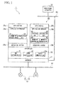
FIG. 1 is a block diagram of the main parts of the configuration of a process control system according to the first embodiment of the present invention. As shown inFIG. 1 , a process control system 1 of the present invention has a plurality offield devices 10, a controller 20 (process control apparatus), and amonitoring apparatus 30, and thecontroller 20controls field device 10 under monitoring by themonitoring apparatus 30, thereby controlling an industrial process implemented in a plant (not shown). In the process control system 1 of the present embodiment, it is possible to update (also called "online version upgrade", and "online rev-up") the operating system used in thecontroller 20 under control by themonitoring apparatus 30. The word "update" includes meanings of downloading a new operating system, installing, booting, verifying by comparing a new operating system with an old operating system, switching to the new operating system. - In this case, the
field devices 10 and thecontroller 20 are connected to the field network N1 and thecontroller 20 and themonitoring apparatus 30 are connected to the control network N2. The field network N1 is, for example, a cable network laid throughout an on-site location in a plant. The control network N2 is, for example, a cable network making connections between the plant on-site location and a monitoring room. The field network N1 and the control network N2 may alternatively be wireless networks. - The
field devices 10 are, for example, sensor devices such as flowmeters and temperature sensors, valve devices such as a flow control valve or open-close valve, actuator devices such as fans and motors, and other devices installed in a plant. As an aid to understanding the description,FIG. 1 shows, of thefield devices 10 installed in the plant, asensor device 11 that measures the flow amount of a fluid and avalve device 12 that controls (actuates) a flow amount of a fluid. - The
field devices 10 operate in accordance with control data that is transmitted from thecontroller 20 via the field network N1. For example, if a request to transmit measurement data (data indicating the result of measuring the flow amount of a fluid) is transmitted to thesensor device 11 from thecontroller 20, thesensor device 11 transmits measurement data to thecontroller 20 via the field network N1. If control data (data controlling an opening) is transmitted to thevalve device 12 from thecontroller 20, thevalve device 12 makes the opening of the valve passing the fluid the opening instructed by the control data. - Under the monitoring by the
monitoring apparatus 30, thecontroller 20 collects measurement data from the field devices 10 (for example, the sensor device 11) and also controls the field devices 10 (for example, the valve device 12) based on the collected measurement data. Thecontroller 20 also, based on instructions from themonitoring apparatus 30, updates the operating system that it itself uses. This function of thecontroller 20 is implemented by software being read into a computer, with software and hardware resources operating in concert. - Specifically, the function of the
controller 20 is implemented byhardware 21, which is composed of an MPU (micro processing unit, microprocessor) and memory or the like, executing an installed program. In this case, a program for implementing a hypervisor 22 (virtualization unit), a program for implementingoperating systems application managers controller 20. - The example of updating the
operating system 23a used in thecontroller 20 to theoperating system 23b in the present embodiment will be described. - In order to do this, a program for implementing the
operating system 23b and a program for implementing theapplication manager 24b are downloaded from themonitoring apparatus 30 and installed when updating theoperating system 23a. Although details will be described later, theapplication 25b is theapplication 25a in theoperating system 23a (application manager 24a) restored into theoperating system 23b (application manager 24b). - The
hypervisor 22 runs virtually inhardware 21 in place of hardware, and is provided for the purpose of causing independent operation of theoperating system 23a,application manager 24a, andapplication 25a, and therespective operating system 23b,application manager 24b, andapplication 25b. Providing thehypervisor 22 enables the replacement ofhardware 21 without switching theoperating systems application managers applications - In this case, providing the
hypervisor 22 enables theoperating systems application managers applications - (a) Running of only the
operating system 23a, theapplication manager 24a, and theapplication 25a - (b) Running of only the
operating system 23b, theapplication manager 24b, and theapplication 25b - (c) Parallel running of the
operating system 23a,application manager 24a, andapplication 25a with theoperating system 23b,application manager 24b, andapplication 25b - As shown in
FIG 1 , thehypervisor 22 has an input distribution unit 41 (distribution unit), an output acquisition unit 42 (acquisition unit), and anoutput comparison unit 42a. Theinput distribution unit 41 distributes measurement data and statuses from the field devices 10 (for example, the sensor device 11) to each of theoperating systems operating systems applications application managers - The
output acquisition unit 42 acquires the outputs of theoperating systems operating system 23a to the field devices 10 (for example, the valve device 12). The outputs of theoperating systems applications application managers operating systems output acquisition unit 42 passes the acquired outputs of theoperating systems output comparison unit 42a. -
Output comparison unit 42a compares the outputs from the output acquisition unit 42 (the outputs of theoperating systems output comparison unit 42a verifies whether or not the compared contents of the outputs of theoperating systems operating systems - Although it will be described later in detail, the reason for providing the
input distribution unit 41, theoutput acquisition unit 42, and theoutput comparison unit 42a in thehypervisor 22 is to align the operating timing of theoperating system 23a and theapplication 25a with that of theoperating system 23b and theapplication 25b, which operate in parallel thereto, to verify the operation of the parallel-operating operating system 23a andapplication 25a and theoperating system 23b andapplication 25b, so that the processing ofapplication 25a after the operational verification is carried on of theapplication 25b seamlessly. That is, this is done to verify whether or not thenew operating system 23b andapplication 25b running in theoperating system 23b operate in the same manner as theoriginal operating system 23a andapplication 25a, so that it is possible for thenew operating system 23b andapplication 25b processing to pick up from theoriginal operating system 23a andapplication 25a, with the application operation remaining as is. - The
operating systems hypervisor 22 and, for example, each performs the process management and memory management required to have theapplications operating system 23a is the original operating system, and theoperating system 23b is the new operating system. - The
application managers application 25a in theoperating system 23a (application manager 24a) to be restored into theoperating system 23b (application manager 24b) as theapplication 25b. Theapplication managers new operating system 23b andapplication 25b are operating in the same manner as theoriginal operating system 23a andapplication 25a. - The
application manager 24a is middleware installed between theoperating system 23a and theapplication 25a. Thisapplication manager 24a has an information recording unit 51 (recording unit) and atransmission unit 52, and performs collection, recording, and transmission of information required for restoration of theapplication 25a into theoperating system 23b (application manager 24b) as theapplication 25b and information used in verifying the operation of thenew operating system 23b and theapplication 25b. - The
information recording unit 51 records information (first information) required for restoration of theapplication 25a and information (second information) that is passed between theoperating system 23a and theapplication 25a. Specifically, theinformation recording unit 51 records the following information. - The first information includes loaded programs and all data that are resident in a memory space of a process of the
application 25a. For example, the data includes contents of heap area and shared memory space used by theapplication 25a. - The second information includes contents sent from the
application 25a to theoperating system 23a, and contents sent from theoperating system 23a to theapplication 25a. For example, the second information includes contents of system calls and signals. - The
transmission unit 52 reads information recorded in theinformation recording unit 51 and transmits it to theapplication manager 24b. Because theapplication manager 24b is not loaded except for a time when the operation system is updated,transmission unit 52 does not send the information recorded in theinformation recording unit 51 to theapplication manager 24b. - The
application manager 24b is middleware installed between theoperating system 23b and theapplication 25b. Theapplication manager 24b has a receivingunit 61, arestoration unit 62, aninformation recording unit 63, and an information comparison unit 64 (comparison unit), and performs processing that restores theapplication 25b into theoperating system 23b (application manager 24b) and processing that verifies the operation of thenew operating system 23b andapplication 25b. - The receiving
unit 61 receives information transmitted from the transmittingunit 52 of theapplication manager 24a and outputs the information to therestoration unit 62 or theinformation comparison unit 64. Therestoration unit 62 uses the information output from the receivingunit 61 to restore theapplication 25a in theoperating system 23a (application manager 24a) into theoperating system 23b (application manager 24b) as theapplication 25b. - In this case, the transmission of information from the
transmission unit 52 to the receivingunit 61 is performed using a function of the operating system (for example a socket interface) via theoperating systems operating system 23a, thehypervisor 22 and theoperating system 23b in that sequence. - The
information recording unit 63 records information passed between theoperating system 23b and theapplication 25b. Theinformation comparison unit 64 compares information output from the receiving unit 61 (information passed between theoperating system 23a and theapplication 25a) and information recorded in the information recording unit 63 (information passed between theoperating system 23b and theapplication 25b). Theinformation comparison unit 64 verifies whether or not the contents of the compared information are the same and verifies whether or not the timing gap of the compared information is within a pre-established allowable range. - The
applications operating systems application managers field devices 10 required to perform process control (for example, collection of measured data and the like from thesensor device 11 and transmission of control data to thevalve sensor 12, and the like). As described above, although theapplication 25b is theapplication 25a restored into theoperating system 23b (application manager 24b), theapplications - The
monitoring apparatus 30 is implemented by, for example, a computer, and is operated by an operator to monitor a process. Specifically, themonitoring apparatus 30 monitors and manages theoperating systems applications controller 20. Also, themonitoring apparatus 30 instructs thecontroller 20 performing the process control in accordance with an instruction from an operator. Themonitoring apparatus 30, based on an instruction from an operator, also instructs thecontroller 20 to update theoperating system 23a. - Next, the operation of the process control system 1 constituted as described above will be described. The following is first a description of the operation of the
controller 20 before switching from theoperating system 23a to theoperating system 23b (pre-switching operation), followed by a description of operation when switching from theoperating system 23a to theoperating system 23b (switching operation). -
FIG. 2 is a drawing for describing the pre-switching operation of the controller in the first embodiment of the present invention. As shown inFIG. 2 , before theoperating system 23a is updated, theoperating system 23a runs in thehypervisor 22 in thecontroller 20, with theapplication manager 24a operating in theoperating system 23a, and theapplication 25a running in theapplication manager 24a. - In this state, when measurement data from the
sensor device 11 is input to thecontroller 20, the measurement data is input to theapplication 25a via theinput distribution unit 41 provided in thehypervisor 22, theoperating system 23a, and theapplication manager 24a, in that sequence. When this occurs, information passed between theoperating system 23a and theapplication 25a is recorded in theinformation recording unit 51 and output to the transmittingunit 52. - When measurement data from the
sensor device 11 is input to theapplication 25a, the control amount of thevalve device 12 is determined depending upon the input measurement data, and control data indicating that control amount is output from theapplication 25a. This control data is output to thevalve device 12 via theapplication manager 24a, theoperating system 23a, and theoutput acquisition unit 42 of thehypervisor 22, in that sequence. When this occurs, the information passed between theoperating system 23a and theapplication 25a is recorded in theinformation recording unit 51 and output to thetransmission unit 52. - During the above operations, information required for the restoration of the
application 25a, as described above, and information passed between theoperating system 23a and theapplication 25a are recorded in the information recording unit 51 (first step). Measurement data and control data output to thetransmission unit 52 from theinformation recording unit 51 is discarded during theapplication manager 24b is not loaded. - During the above operations, a program for implementing the
operating system 23b and a program for implementing theapplication manager 24b are downloaded to thecontroller 20 from themonitoring apparatus 30 and installed. The installing of these programs is done at an arbitrary timing before the start of the updating of theoperating system 23a, so that the process control of thecontroller 20 described above are not hindered. Also, if a program has been already downloaded, the existing program is overwritten with a later-downloaded program to be installed. -
FIG. 3 is a flowchart of the controller switching operation in the first embodiment of the present invention. The processing in the flowchart ofFIG. 3 starts at the timing of the output from themonitoring apparatus 30 of an operating system updating instruction to thecontroller 20. When processing starts, based on an instruction from themonitoring apparatus 30, thecontroller 20 performs processing to start thenew operating system 23b (step S11). - Specifically, processing for executing the programs downloaded during the "pre-switching processing" described above (the program for implementing the
operating system 23b and the program for implementing theapplication manager 24b) is performed. By this processing, theoperating system 23b runs in thehypervisor 22, and theapplication manager 24b runs in theoperating system 23b (refer toFIG. 1 ). - Next, processing to transfer information that was recorded in the
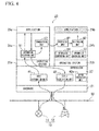
information recording unit 51 of theapplication manager 24a (step S12) and processing to restore theapplication 25a into thenew operating system 23b as theapplication 25b (step S13, namely "second step") are performed in sequence by thecontroller 20.FIG. 4 is a drawing for describing the application restoration processing in the first embodiment of the present invention. - As shown in
FIG. 4 , the process control, the transfer of information and restoration of the application are done by thecontroller 20 inputting measurement data from thesensor device 11 and outputting control data to thevalve device 12 in the same manner as the above-described pre-switching operation. That is, transfer of information and restoration of the application are performed at thecontroller 20 so as hinder neither the input of measurement data nor the output of control data. - Specifically, at step S12, in the
application manager 24a processing is done that reads out the information that was stored in theinformation recording unit 51 and transmits the information to theapplication manager 24b by thetransmission unit 52. In response, theapplication manager 24b does processing to receive the information transmitted from thetransmission unit 52 of theapplication manager 24a and to output the received information to therestoration unit 62. - At step S13 (second step), the
restoration unit 62 of theapplication manager 24b uses the history of the second information included in the transferred and received information to perform processing to make the state of thenew operating system 23b the same as the internal state of theoperating system 23a. Therestoration unit 62 also uses the first information included in the transferred and received information to perform processing to restore theapplication 25a into theoperating system 23b. - In this case, the internal state of the
operating system 23b that, using the second information history, becomes the same as in theoperating system 23a is specifically the following states. - (a) A state of each process making up the
application 25a, which includes management information of each process and information of the parent-child relationship thereof. - (b) A state of IPC (inter process communication) between the processes making up the
application 25a, which includes message communications between the processes and information of synchronization control, exclusion control, and so on. - (c) A state of the
application 25a communicating with outside, which includes a state of the network connection used by theapplication 25a. - If a part of these statuses can be directly acquired and directly reflected by the functions of the
operating system 23a without using the history information, means the same as that which restores the application using the first information may be used. Specifically, an internal state same as that of theoperating system 23a may be restored by restoring the state acquired from theoperating system 23a in theoperating system 23b. - The above-noted processing restores the
application 25a in theoperating system 23a into theoperating system 23b as theapplication 25b, as shown inFIG. 4 . Doing this, in thecontroller 20, theoriginal operating system 23a andapplication 25a and thenew operating system 23b andapplication 25b (application equivalent to theapplication 25a) run in parallel. - When the restoration of the
application 25b is completed, the operation of thenew operating system 23b andapplication 25b is verified. Specifically, the operation when data is input (step S14) and the operation when data is output (step S15) are verified. In this case, verification of the operation when data is input is verification of the operation in the case in which, for example, measurement data from thesensor device 11 is input to thecontroller 20, and verification of the operation when data is output is verification of the operation in the case in which, for example, control data is output to thevalve device 12. -
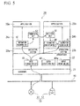
FIG. 5 is a drawing for describing the verification of operation when data is input in the first embodiment of the present invention. As shown inFIG. 5 , when measurement data from thesensor device 11 is input to thecontroller 20, theinput distribution unit 41 provided in thehypervisor 22 performs processing to append a timestamp (time t1) to the measurement data and to distribute it to theoperating system 23a and theoperating system 23b. By distributing the measurement data, the measurement data is input to theoperating system 23a theoperating system 23b with the same timing. - The measurement data distributed to the
operating system 23a is input to theapplication 25a, via theoperating system 23a and theapplication manager 24a, in that sequence. When this occurs, processing is done to record in theinformation recording unit 51 information passed between theoperating system 23a and theapplication 25a and, after appending a timestamp (time t11) thereto, output the information to thetransmission unit 52. The information that was output to thetransmission unit 52 is output to theinformation comparison unit 64, via the receivingunit 61 of theapplication manager 24b. - Along with the above, the measurement data that was distributed to the
operating system 23b is input to theapplication 25b, via theoperating system 23b and theapplication manager 24b, in that sequence. When this occurs, processing is performed to record in theinformation recording unit 63 the information passed between theoperating system 23b and theapplication 25b and also to append a timestamp (time t12) thereto and output the information to theinformation comparison unit 64. - When information from the receiving
unit 61 and information from theinformation recording unit 63 are input, theinformation comparison unit 64 compares the information and verifies whether or not the compared information are the same and verifies whether or not the timing gap between the compared information is within a pre-established allowable range. Specifically, in the former verification, for example, a verification is made as to whether or not contents (arguments and returned values) of the system call requested to theoperating systems operating systems application operating systems operating systems operating systems - In the latter verification, using the timestamps that were appended to the information being compared, a verification is done as to whether or not difference in the times required for the processing of the
operating systems applications operating system 23a (t11 - t1) and the processing time in theoperating system 23b (t12 - t1) is within a pre-established allowable range (for example, 1% of the control time period). Theinformation comparison unit 64, depending upon the results of the above-noted verification, notifies themonitoring apparatus 30 that an abnormality has occurred. -
FIG. 6 is a drawing for describing the verification of operation when data is output in the first embodiment of the present invention. When control data is output from theapplication 25a, the output control data is input to theapplication manager 24a and, at theinformation recording unit 51, has a timestamp (time t21) appended thereto, and is output to theoutput acquisition unit 42 of thehypervisor 22, via theoperating system 23a. When this occurs, processing is performed to record in theinformation recording unit 51 the information passed between theoperating system 23a and theapplication 25a into, and also to append the above-noted time stamp (time t21) thereto and output the information to theinformation comparison unit 64. The information that was output to thetransmission unit 52 is output to theinformation comparison unit 64 via the receivingunit 61 of theapplication manager 24b. - Along with the above, when the control data is output from the
application 25b, the output control data is input to theapplication manager 24b, has a timestamp (time t22) appended thereto at theinformation recording unit 63, and is output to theoutput acquisition unit 42 of thehypervisor 22, via theoperating system 23b. When this occurs, processing is performed that records in theinformation recording unit 63 the information passed between theoperating system 23b and theapplication 25b, and also that appends the above-noted timestamp (time t22) to the information, and outputs the information to theinformation comparison unit 64. - When the information from the receiving
unit 61 and information from theinformation recording unit 63 are input, theinformation comparison unit 64 compares these information and verifies whether or not the compared information is the same and also verifies whether or not the timing gap between the compared information is within a pre-established allowable range. Specifically, in the former verification, the verification performed is the same as described for the case of "verification of operation when data is input," usingFIG. 5 . In the latter verification, using the timestamp (time t21) that was appended to the information from the receivingunit 61 as a reference, the verification is performed as to whether or not the timestamp (time t22) that was appended to the information from theinformation recording unit 63 is within a pre-established allowable range. Theinformation comparison unit 64, depending upon the results of the above-noted verification, notifies themonitoring apparatus 30 that an abnormality has occurred. - When control data from the
operating systems output acquisition unit 42, theoutput acquisition unit 42 outputs the control data output from theoperating system 23a to thevalve device 12. Theoutput acquisition unit 42 appends a timestamp (time t31) to the control data from theoperating system 23a and also appends a timestamp (time t32) to the control data from theoperating system 23b and passes these to theoutput comparison unit 42a. Theoutput comparison unit 42a compares the control data passed to it from theoutput acquisition unit 42 and, in the same manner as theinformation comparison unit 64, verifies whether or not the contents of the compared control data are the same and also verifies whether or not the timing gap between the compared control data is within a pre-established allowable range. - In this case, in the former verification, for example, the verification is performed as to whether or not the control data from the
operating systems systems - Specifically, verification is done as to whether or not the difference between the processing time in the
operating system 23a (t31 - t21) and the processing time in theoperating system 23b (t32 - t22) is within a pre-established allowable range. Alternatively, verification is done as to whether or not the difference between the timestamps appended to the control data when input is made to the output acquisition unit 42 (t31 and t32) is within a pre-established allowable range. Theoutput comparison unit 42a, depending upon the result of the above-noted verification, notifies themonitoring apparatus 30 that an abnormality has occurred. In this manner, the verification of operation when data is output makes a comparison by theinformation comparison unit 64 of theapplication manager 24b and makes a comparison by theoutput comparison unit 42a of thehypervisor 22. - In the above-described operational verifications (verification of operation when data is input and verification of operation when data is output), depending upon the result of the verifications, notification is made to the
monitoring apparatus 30 that an abnormality has occurred. When this occurs, in addition to the notification made to themonitoring apparatus 30, theinformation comparison unit 64 andoutput comparison unit 42a and the like may stop theoperating system 23b and theapplication 25b as abnormal operation has occurred. - Next, the
monitoring apparatus 30 judges whether or not the operational verification has terminated (step S16). If the judgment is that the operational verification has not yet terminated (NO judgment result at step S16), the operational verification is continued (steps S14 and S15). If, however, the judgment is that the operational verification has terminated (YES judgment result at step S16), themonitoring apparatus 30 judges whether or not the operational verification has terminated normally (step S17). - If the judgment is that the operational verification has terminated normally (YES judgment result at step S17), the
monitoring apparatus 30 transmits an operational verification normal termination instruction to thecontroller 20. When the operational verification normal termination instruction is sent, theoutput comparison unit 42a of thecontroller 20 outputs to thevalve device 12 control data from theoperating system 23b in place of the control data from theoperating system 23a. Thecontroller 20 performs processing to stop theoriginal operating system 23a,application manager 24a, andapplication 25a, thereby switching the operating systems (step S18). - In contrast to the above, if the judgment is that the operational verification terminated abnormally (NO judgment result at step S 17), the
monitoring apparatus 30 transmits an operational verification abnormal termination instruction to thecontroller 20. When the operational verification abnormal termination instruction is sent, if thenew operating system 23b,application manager 24b, andapplication 25b were not stopped at thecontroller 20, it performs processing to stop them (step S 19). This results in the state enabling a retry of the operating system updating. - As described above, in the present embodiment, the
hypervisor 22 is run in thehardware 21, in place of hardware, thereby enabling parallel operation of theoriginal operating system 23a and thenew operating system 23b. The information required for restoring theapplication 25a and information passed between theoperating system 23a and theapplication 25a are then recorded in theinformation recording unit 51 and, using the information recorded in theinformation recording unit 51, theapplication 25a running in theoperating system 23a is restored into theoperating system 23b. - This enables updating of the
operating system 23a to theoperating system 23b without stopping the process control system 1. Also, because theapplication 25a in theoperating system 23a and theapplication 25b in theoperating system 23b run in parallel and the operating systems are switched after verifying the operation of theapplication 25b, the continued operation of theapplication 25b in thenewer operating system 23b of which version upgraded can be assured. - In addition, because parallel operation means that at least one of the
applications field devices 10 performed by the application will not stop, including during the time of updating the operating system. Additionally, during the time of updating the operating system, because restoration is made to the configuration before updating by just stopping theoperating system 23b and theapplication 25b, even if the operational verification judges that there is an abnormality, it is possible to re-try the updating of the operating system any number of times. - The above-described embodiment records the information passed between the
operating system 23a and theapplication 25a, that is, the second information, into theinformation recording unit 51 and records the information passed between theoperating system 23b and theapplication 25b into theinformation recording unit 63 and ultimately compares, with theinformation comparison unit 64, information that is the combination of the second information and a timestamp appended by a series of processing and information that is the combination of the information passed between theoperating system 23b and theapplication 25b and a timestamp appended by a series of processing. - However, because not only the second information, but also the first information required for restoration of the application changes because of data input and data output, even if the first information is used in place of the second information, it is possible to perform an operational verification in the same manner as in the case of using the second information.
- In this case, the first information, rather than the second information, is recorded into the
information recording unit 51, and theinformation recording unit 63, instead of the information passed between theoperating system 23b and theapplication 25b, records information of theapplication 25b corresponding to the first information of theapplication 25a restored into theoperating system 23b. - In this case, the information corresponding to the first information is information similar to the information required for restoration of the application, this referring to, for example, downloaded programs and data resident in a memory space.
- Additionally, the
information comparison unit 64 may compare not only one of the first information and the second information, but rather compare both the first information and the second information. - Because the first information represents the internal state of the application, comparing both the first information and the second information achieves the effect of enabling a detailed verification of abnormalities. For example, when a comparison of the second information reveals an abnormality, referring also to the results of comparing the first information (location and details of the differences resulting from the comparison) enables verification of whether or not the abnormality is within the scope of anticipated operation of the application in the updated operating system.
- The first information and the second information might be stored at a time of inputting and outputting data. Not only that, the first information and the second information might be compared, for the case of the first information, by storing internal states after important process of the application, for the case of the second information, by storing execution contents of system calls without data input and output.
- As an aid to understanding the above-described embodiment, the description has been for the example of the
original operating system 23a being updated to thenew operating system 23b. For this reason, theapplication manager 24a running in theoriginal operating system 23a has theinformation recording unit 51, and the transmittingunit 52, and theapplication manager 24b running in thenew operating system 23b has the elements ranging from the receivingunit 61 to theinformation comparison unit 64. - It can also be envisioned that the
new operating system 23b is updated to an even newer operating system because of reasons of detecting newer vulnerability, and so on. For this reason, the configuration of the application manager running in the operating system may have both theapplication managers FIG 1 , and may be made switchable by setting the operating mode so as to cause eitherapplication managers - The above-described embodiment has been described for the case in which the
monitoring apparatus 30 monitors thecontroller 20 and instructs thecontroller 20 to update theoperating system 23a. However, themonitoring apparatus 30 can be envisioned as being configured to be separated into functions that perform the instructions and monitoring occurring in flow of the above-noted embodiment (updating monitoring functions) and functions that perform other instructions and monitoring (control monitoring functions and the like). In such a configuration, the updating and monitoring functions may be incorporated into a computer performing control system settings, such as an engineering workstation, or a computer or the like in which a system updating program is stored or which runs a server that manages states of applications (an implementation example being Windows (registered trademark) Server Update Services). - In addition to the above, when making a normal termination to the operational verification, if it is not necessary to monitor the judgment regarding the switching of the operating systems by the
monitoring apparatus 30, for example, if absolutely no abnormality is detected by theinformation comparison unit 64 for a certain period of time, theinformation comparison unit 64 oroutput comparison unit 42a may, in place of themonitoring apparatus 30, give an operational verification termination instruction so that the operating system switching is done automatically. In this case, the condition for switches the operating systems is input beforehand to theinformation comparison unit 64 oroutput comparison unit 42a, via themonitoring apparatus 30 or the like. - Also, if the switching of the
operating systems information recording unit 51 and theinformation recording unit 63 may reducing the amount of the first information and the second information by compressing so as to reduce the comparing process of theinformation comparison unit 64 and theoutput comparison unit 42a. Specifically, processing to convert a part of the information to hash values using a one-way hash function such as MD5, calculating differences between previous information and current information so that positions of the differences and contents of the differences are output, or the like, may be done. - Also, after the operational verification of the
operating system 23b ends in a normal way, there may be a case where thecontroller 20 permanently operates the set of theoperating system 23b, theapplication manager 24b, and theapplication 25b instead of the set of theoperating system 23a, theapplication manager 24a, and theapplication 25a. In the case, it is necessary that a program implementing theapplication 25b is installed on theoperating system 23b so that theapplication 25b can be operated after rebooting thecontroller 20. The reason is that theapplication 25b restored by therestoration unit 62 is deleted because theapplication 25b is stored in a volatile memory. -
FIG. 7 is a block diagram showing the main part of the configuration of a process control system according to the second embodiment of the present invention. InFIG. 7 , constituent elements that are the same as inFIG. 1 are assigned the same reference numeral. As shown inFIG. 7 , a process control system 2 of the present embodiment has twocontrollers controller 20, thesecontrollers - The
controller 20a has ahypervisor 22a implemented inhardware 21 a, with theoperating system 23a, theapplication manager 24a, and theapplication 25a implemented in thehypervisor 22a. Thehypervisor 22a, in addition to having theinput distribution unit 41 and theoutput acquisition 42 of thehypervisor 22 ofFIG. 1 , has acommunication unit 43. Thecommunication unit 43, for example, communicates with thehypervisor 22b implemented in thecontroller 20b, via the inter-hypervisor network N3. - The
controller 20b has ahypervisor 22b implemented inhardware 21b, with theoperating system 23b, theapplication manager 24b, and theapplication 25b implemented in thehypervisor 22b. Thehypervisor 22b, in addition to having theoutput comparison unit 42a of thehypervisor 22 ofFIG. 1 , has acommunication unit 44. Thecommunication unit 44, for example, communicates with thehypervisor 22a implemented in thecontroller 20a, via the inter-hypervisor network N3. The provision of theoutput comparison unit 42a in the hypervisor 22b of thecontroller 20b is so that the operation of thecontroller 20a in which theoriginal operating system 23a runs is not affected. - In this case, mutual communication between the
communication unit 43 provided in thehypervisor 22a of thecontroller 20a and thecommunication unit 44 provided in the hypervisor 22b of thecontroller 20b logically integrates and runs thehypervisors operating systems input distribution unit 41, and enables acquisition by theoutput acquisition unit 42 of control data output from theoperating system 23a and output thereof to theoutput comparison unit 42a. - Control data output from the
operating system 23b is directly output to theoutput comparison unit 42a. Similar to the first embodiment, control data acquired from theoperating system 23b is not output to thevalve device 12 and is only compared by theoutput comparison unit 42a. For this reason, in the second embodiment, it is sufficient to directly output to theoutput comparison unit 42a existing on thesame controller 20b. - The inter-hypervisor network N3, provided separately from the field network N1 and the control network N2, is used for communication between the
communication unit 43 provided in thehypervisor 22a of thecontroller 20a and thecommunication unit 44 provided in the hypervisor 22b of thecontroller 20b. The inter-hypervisor network N3 is provided to prevent communication between thecommunication units - Although the
input distribution unit 41 and theoutput acquisition unit 42 are provided in thehypervisor 22a in the example shown inFIG. 7 , theinput distribution unit 41 and theoutput acquisition unit 42 may be provided in thehypervisor 22b. However, if thecontroller 20a is, for example, the controller that controls the actual process and thecontroller 20b is the new controller to be used, if it is desired to achieve stable operation by the previous operating track record, it is desirable that theinput distribution unit 41 and theoutput acquisition unit 42 be provided in thehypervisor 22a. - When the process control system 2 having the above-noted configuration updates the
controller 20a, processing basically the same as that shown in the flowchart ofFIG. 3 is performed. That is, first, in thecontroller 20a information required for the restoration of the above-describedapplication 25a and information passed between theoperating system 23a and theapplication 25a are recorded in the information recording unit 51 (first step). Next, using this information, theapplication 25a is restored into thecontroller 20b as theapplication 25b (step S13, namely "second step"). After that, in thecontroller 20b, verification of the operation when data is input (step S14) and verification of the operation when data is output (step S15) are performed. - As noted above, in this embodiment as well, similar to the first embodiment, information required for the restoration of the
application 25a and information passed between theoperating system 23a and theapplication 25a are recorded in theinformation recording unit 51. Then, using the information that was recorded in theinformation recording unit 51, theapplication 25a to be run in theoperating system 23a is restored into theoperating system 23b. - Doing the above enables the updating of the
operating system 23a to theoperating system 23b without stopping the process control system 2. Also, because theapplication 25a in theoperating system 23a and theapplication 25b in theoperating system 23b run in parallel, the continued operation of theapplication 25b running in thenewer operating system 23b of which version upgraded can be assured. - In addition, because parallel operation means that at least one of the
applications field devices 10 by the application will not stop, including during the time of updating of the operating system. Additionally, during the operating system updating, because restoration is made to the configuration before updating by just stopping theoperating system 23b and theapplication 25b, even if the operational verification judges that there is an abnormality, it is possible to re-try the updating of the operating system any number of times. - In order to switch the output of control data to the
valve device 12 to the output from thenew controller 20b and then stop of theoriginal controller 20a (i.e., perform controller replacement), it is necessary for thenew controller 20b to have functionality that is an alternative to theinput distribution unit 41 and theoutput acquisition unit 42 of theoriginal controller 20a. - For this reason, the configuration of the virtualization unit operating in the hardware is made to have the configurations of both the
virtualization units FIG. 7 , enabling switching of eithervirtualization unit 22a orvirtualization unit 22b to run, by setting the operating mode. At the step inFIG. 3 of switching the operating system in the second embodiment (step S18), the confguration of the virtualization unit of thenew controller 20b is switched to that of thevirtualization unit 22a, and control data output from theoperating system 23b is passed to the output acquisition unit of thenew controller 20b. When switching is done, the input of control data to theoperating system 23b is made from the input distribution unit of thenew controller 20b. Doing the above eliminates the need for exchange with theoriginal controller 20a from thenew controller 20b that has been switched to and enables the stopping of theoriginal controller 20a. - In the second embodiment, the
information comparison unit 64 and theoutput comparison unit 42a are caused to operate in thecontroller 20b in which thenew operating system 23b runs. For this reason, it is possible to verify the updating of the operating system and to verify the operation after updating, without influencing the operation of theapplication 25a andoperating system 23a that are running in thecontroller 20a. - In the first and second embodiment described above, because the
information comparison unit 64 and theoutput comparison unit 42a perform comparisons, the operation can be verified, focusing on the hypervisor, the operating system, and the application, and on the series of operations of the operating system and the hypervisor. This enables more certain knowledge of a location of a problem in operation. This also facilitates the judgment of the location of an operational problem, because this reduces the amount of information needed to be verified, compared to the case in which each operating step is tracked by debugging and the like, focusing on the operating system or the application operation. - Although a process control apparatus, a process control system, and an updating method therefor according to embodiments of the present invention have been described above, the present invention is not restricted to the above-described embodiments, and can be freely modified within the scope thereof. For example, although the foregoing descriptions of the embodiments have been examples in which a virtual environment that can run a plurality of operating systems or applications is implemented in the
controller hypervisors hypervisor 22. For example, the above-noted virtual environment may be implemented with hardware. - Also, although the above descriptions of the embodiments took the example of
field devices 10 capable of digital communication via the field network N 1, field devices that perform input and output of analog signals may be used. When such field devices are used, an I/O node that converts signals (analog signals) input and output by the field devices and signals (digital signals) communicated via the field network N1 can be connected to the field network N1, and the I/O node can be connected to the field devices by an analog transmission path (for example, a transmission path used for transmission of 4 to 20 mA signals). - Although the first and second embodiments were described for data input and data output with respect to the
field devices 10 and themonitoring apparatus 30 passing through field network N1 and control network N2, it can be envisioned that, for example, thehardware field devices 10 and themonitoring apparatus 30, but are rather processed internally in thehardware - The term "configured" is used to describe a component, unit or part of a device includes hardware and/or software that is constructed and/or programmed to carry out the desired function.
- While preferred embodiments of the invention have been described and illustrated above, it should be understood that these are exemplary of the invention and are not to be considered as limiting. Additions, omissions, substitutions, and other modifications can be made without departing from the scope of the present invention. Accordingly, the invention is not to be considered as being limited by the foregoing description, and is only limited by the scope of the appended claims.
Claims (15)
- A process control apparatus that controls an industrial process implemented in a plant, the process control apparatus comprising:a virtualization unit configured to operate in hardware;first and second operating systems configured to run in the virtualization unit;an application configured to run in the first operating system, and configured to control the industrial process by communicating with field devices performing at least one of measurement and actuation required for control of the industrial process;a recording unit configured to record a first information required for restoration of the application and a second information passed between the first operating system and the application; anda restoration unit configured to use a history of the second information recorded in the recording unit to set the second operating system to the same state as the internal state of the first operating system, and configured to use the first information to restore the application running in the first operating system into the second operating system.
- The process control apparatus according to claim 1, further comprising a comparison unit configured to perform at least one of an operation of comparing the first information with information corresponding to the first information of the application restored in the second operating system and an operation of comparing the second information with information that is passed between the second operating system and the application restored in the second operating system.
- The process control apparatus according to claim 2, wherein the comparison unit performs a verification of whether or not the contents of the compared information are the same and a verification of whether or not the timing gap of the compared information is within a pre-established allowable range.
- The process control apparatus according to claim 2, wherein the recording unit is provided within a first middleware installed between the first operating system and the application, and the restoring unit and the comparison unit are provided within a second middleware installed between the second operating system and the application restored in the second operating system.
- The process control apparatus according to claim 1, further comprising:a distribution unit configured to be provided in the virtualization unit to distribute information from the field devices to the first and second operating systems; andan acquisition unit configured to be provided in the virtualization unit to acquire outputs of the first and second operating systems and output one thereof to the field devices.
- The process control apparatus according to claim 5, further comprising an output comparison unit configured to compare the outputs of the first and second operating systems acquired by the acquisition unit.
- The process control apparatus according to claim 6, wherein the output comparison unit performs a verification of whether or not the content of the compared outputs of the first and second operating systems are the same and a verification of whether or not the timing gap of the compared outputs of the first and second operating systems is within a pre-established allowable range.
- The process control apparatus according to claim 1, wherein the hardware is configured to be connected to the field devices via a first network.
- The process control apparatus according to claim 8, wherein the hardware is configured to be connected to a monitoring apparatus via a second network, the monitoring apparatus monitoring the first and second operating systems and the application.
- A process control system that controls an industrial process implemented in a plant, the process control system comprising:a first process control apparatus that has:a first virtualization unit configured to run in first hardware;a first operating system configured to run in the first virtualization unit;an application configured to run in the first operating system, and configured to control the industrial process by communicating with field devices performing at least one of measurement and actuation required for control of the industrial process; anda recording unit configured to record a first information required for restoration of the application and a second information passed between the first operating system and the application; anda second process control apparatus that has:a second virtualization unit configured to run in second hardware and logically integrated with the first virtualization unit;a second operating system configured to run in the second virtualization unit; anda restoration unit configured to use a history of the second information recorded in the recording unit to set the second operating system to the same state as the internal state of the first operating system, and configured to use the first information to restore the application running in the first operating system into the second operating system.
- The process control system according to claim 10, further comprising a comparison unit configured to perform at least one of an operation of comparing the first information with information corresponding to the first information of the application restored in the second operating system and an operation of comparing the second information with information that is passed between the second operating system and the application restored in the second operating system.
- The process control system according to claim 11, wherein the comparison unit performs a verification of whether or not the contents of the compared information are the same and a verification of whether or not the timing gap of the compared information is within a pre-established allowable range.
- The process control system according to claim 11, wherein the recording unit is provided within a first middleware installed between the first operating system and the application, and the restoring unit and the comparison unit are provided within a second middleware installed between the second operating system and the application restored in the second operating system.
- An updating method for a process control apparatus that controls an industrial process implemented in a plant, the method comprising:a first step of recording a first information required for restoration of an application and a second information passed between a first operating system that runs in a virtualization unit running in hardware to cause the application to run and the application; anda second step of using a history of the second information recorded by the first step to set a second operating system that runs in the virtualization unit to the same state as the internal state of the first operating system, and using the first information to restore the application that runs in the first operating system into the second operating system.
- An updating method for a process control system having first and second process control apparatuses that control an industrial process implemented in a plant, the method comprising:a first step of recording a first information required for restoration of an application running in the first process control apparatus and a second information passed between a first operating system that runs the application and the application; anda second step of using a history of the second information recorded by the first step to set a second operating system running in the second process control apparatus to the same state as the internal state of the first operating system running in the first process control apparatus and using the first information to restore the application running in the first operating system into the second operating system.
Applications Claiming Priority (1)
| Application Number | Priority Date | Filing Date | Title |
|---|---|---|---|
| JP2013131714A JP5713056B2 (en) | 2013-06-24 | 2013-06-24 | Process control apparatus and system and update method thereof |
Publications (3)
| Publication Number | Publication Date |
|---|---|
| EP2821867A2 true EP2821867A2 (en) | 2015-01-07 |
| EP2821867A3 EP2821867A3 (en) | 2015-05-06 |
| EP2821867B1 EP2821867B1 (en) | 2017-07-26 |
Family
ID=50980179
Family Applications (1)
| Application Number | Title | Priority Date | Filing Date |
|---|---|---|---|
| EP14173272.7A Active EP2821867B1 (en) | 2013-06-24 | 2014-06-20 | Process control apparatus and system and updating method therefor |
Country Status (4)
| Country | Link |
|---|---|
| US (1) | US10310869B2 (en) |
| EP (1) | EP2821867B1 (en) |
| JP (1) | JP5713056B2 (en) |
| CN (1) | CN104238493B (en) |
Cited By (2)
| Publication number | Priority date | Publication date | Assignee | Title |
|---|---|---|---|---|
| EP3073380A1 (en) * | 2015-03-23 | 2016-09-28 | Yokogawa Electric Corporation | Redundant pc system |
| EP3101500B1 (en) * | 2015-06-02 | 2024-02-14 | Siemens Aktiengesellschaft | Control system for a distributed process control of a technical installation and a method for controlling a technical installation |
Families Citing this family (17)
| Publication number | Priority date | Publication date | Assignee | Title |
|---|---|---|---|---|
| JP6265158B2 (en) * | 2015-03-27 | 2018-01-24 | 横河電機株式会社 | Electronics |
| US10185311B2 (en) | 2015-10-08 | 2019-01-22 | King Fahd University Of Petroleum And Minerals | Methods and apparatus to design collaborative automation systems based on data distribution service middleware |
| JP6361641B2 (en) * | 2015-12-03 | 2018-07-25 | 横河電機株式会社 | Field equipment |
| WO2017183717A1 (en) | 2016-04-22 | 2017-10-26 | キッコーマン株式会社 | HbA1c DEHYDROGENASE |
| JP6797588B2 (en) * | 2016-07-22 | 2020-12-09 | 株式会社東芝 | Verification system |
| CN106303609B (en) * | 2016-09-29 | 2019-09-17 | 聚好看科技股份有限公司 | Television applications management method and management server |
| CN106709327A (en) * | 2016-12-07 | 2017-05-24 | 深圳市君格科技有限公司 | Application hiding method and mobile terminal adopting same |
| KR102268796B1 (en) * | 2017-03-28 | 2021-06-23 | 엘에스일렉트릭(주) | Apparatus for processing PLC service based on hypervisor |
| JP6895208B2 (en) * | 2017-10-30 | 2021-06-30 | 東芝三菱電機産業システム株式会社 | Plant controller |
| US11277269B2 (en) * | 2017-12-13 | 2022-03-15 | Arista Networks, Inc. | System and methods for generating and authenticating verifiable network traffic |
| JP7069969B2 (en) * | 2018-03-29 | 2022-05-18 | 株式会社リコー | Information processing equipment, information processing methods and information processing programs |
| JP6819660B2 (en) | 2018-09-26 | 2021-01-27 | 横河電機株式会社 | Process control system, process control device, and program update method |
| CN110347434A (en) * | 2019-05-31 | 2019-10-18 | 口碑(上海)信息技术有限公司 | A kind of processing method and device for calculating equipment application |
| EP3953775A1 (en) * | 2019-06-28 | 2022-02-16 | OMRON Corporation | Method and apparatus for operating an automated system, automated system, and computer-program product |
| DE112019007840T5 (en) | 2019-11-26 | 2022-08-04 | Mitsubishi Electric Corporation | Programmable controller |
| US11314496B2 (en) | 2020-06-25 | 2022-04-26 | Paypal, Inc. | Ultra-fast install and update of an operating system |
| US11200038B1 (en) | 2020-06-25 | 2021-12-14 | Paypal, Inc. | Fast compiling source code without dependencies |
Citations (2)
| Publication number | Priority date | Publication date | Assignee | Title |
|---|---|---|---|---|
| JPH113240A (en) | 1997-06-13 | 1999-01-06 | Yokogawa Electric Corp | Computer system for control |
| WO2005050336A1 (en) | 2003-11-19 | 2005-06-02 | Yokogawa Electric Corporation | Control system |
Family Cites Families (18)
| Publication number | Priority date | Publication date | Assignee | Title |
|---|---|---|---|---|
| US6647301B1 (en) * | 1999-04-22 | 2003-11-11 | Dow Global Technologies Inc. | Process control system with integrated safety control system |
| JP2004038849A (en) * | 2002-07-08 | 2004-02-05 | Toshiba Corp | Control program generation device |
| JP2005266939A (en) * | 2004-03-16 | 2005-09-29 | Hitachi Ltd | Software automatic replacement method |
| JP2006330867A (en) * | 2005-05-24 | 2006-12-07 | Keyence Corp | Management system of program change history, program editing device applied to the system, and program |
| US8108853B2 (en) * | 2006-05-05 | 2012-01-31 | Honeywell International Inc. | Apparatus and method for allowing a fail-back to a prior software release in a process control system |
| US20080244553A1 (en) * | 2007-03-28 | 2008-10-02 | Daryl Carvis Cromer | System and Method for Securely Updating Firmware Devices by Using a Hypervisor |
| US20090132057A1 (en) * | 2007-11-20 | 2009-05-21 | Abb Research Ltd. | Control system for controlling the movements of a plurality of mechanical units |
| JP5155829B2 (en) * | 2008-11-18 | 2013-03-06 | 株式会社東芝 | Programmable controller diagram debugging system, programming device and program thereof |
| US8656297B2 (en) * | 2010-03-31 | 2014-02-18 | Microsoft Corporation | Enhanced virtualization system |
| WO2011150929A1 (en) * | 2010-05-31 | 2011-12-08 | Vestas Wind Systems A/S | A computer system and method for controlling and/or monitoring a wind power plant |
| US9323921B2 (en) * | 2010-07-13 | 2016-04-26 | Microsoft Technology Licensing, Llc | Ultra-low cost sandboxing for application appliances |
| CN102122157B (en) * | 2010-12-27 | 2013-01-30 | 唐山建龙实业有限公司 | Redundancy architecture control system and method thereof capable of keeping original system function and performance |
| JP5728261B2 (en) * | 2011-03-11 | 2015-06-03 | 本田技研工業株式会社 | Equipment operation state data acquisition device and equipment operation state management system |
| US9158561B2 (en) * | 2011-08-18 | 2015-10-13 | Vmware, Inc. | Systems and methods for modifying an operating system for a virtual machine |
| US8881139B1 (en) * | 2011-10-25 | 2014-11-04 | Infinite Corporation | Legacy application rehosting system |
| JP5561298B2 (en) * | 2012-03-23 | 2014-07-30 | 横河電機株式会社 | Process control system |
| JP5660082B2 (en) | 2012-07-03 | 2015-01-28 | 横河電機株式会社 | Process control apparatus and system |
| JP5967215B2 (en) * | 2012-11-07 | 2016-08-10 | 富士通株式会社 | Information processing apparatus, program, and virtual machine migration method |
-
2013
- 2013-06-24 JP JP2013131714A patent/JP5713056B2/en active Active
-
2014
- 2014-06-19 US US14/309,436 patent/US10310869B2/en active Active
- 2014-06-20 CN CN201410281786.9A patent/CN104238493B/en active Active
- 2014-06-20 EP EP14173272.7A patent/EP2821867B1/en active Active
Patent Citations (4)
| Publication number | Priority date | Publication date | Assignee | Title |
|---|---|---|---|---|
| JPH113240A (en) | 1997-06-13 | 1999-01-06 | Yokogawa Electric Corp | Computer system for control |
| WO2005050336A1 (en) | 2003-11-19 | 2005-06-02 | Yokogawa Electric Corporation | Control system |
| US20070078980A1 (en) | 2003-11-19 | 2007-04-05 | Yokogawa Electric Corporation | Control system |
| JP4399773B2 (en) | 2003-11-19 | 2010-01-20 | 横河電機株式会社 | Control system |
Cited By (3)
| Publication number | Priority date | Publication date | Assignee | Title |
|---|---|---|---|---|
| EP3073380A1 (en) * | 2015-03-23 | 2016-09-28 | Yokogawa Electric Corporation | Redundant pc system |
| US10268484B2 (en) | 2015-03-23 | 2019-04-23 | Yokogawa Electric Corporation | Redundant PC system |
| EP3101500B1 (en) * | 2015-06-02 | 2024-02-14 | Siemens Aktiengesellschaft | Control system for a distributed process control of a technical installation and a method for controlling a technical installation |
Also Published As
| Publication number | Publication date |
|---|---|
| CN104238493A (en) | 2014-12-24 |
| CN104238493B (en) | 2017-04-12 |
| EP2821867B1 (en) | 2017-07-26 |
| US10310869B2 (en) | 2019-06-04 |
| US20140379134A1 (en) | 2014-12-25 |
| EP2821867A3 (en) | 2015-05-06 |
| JP5713056B2 (en) | 2015-05-07 |
| JP2015005258A (en) | 2015-01-08 |
Similar Documents
| Publication | Publication Date | Title |
|---|---|---|
| US10310869B2 (en) | Process control apparatus and system and updating method therefor | |
| US9261868B2 (en) | Process control system | |
| US6898542B2 (en) | On-line device testing block integrated into a process control/safety system | |
| JP2010044782A (en) | Method and system for establishing redundancy context in process control system with first and second application stations, method and system for maintaining/managing redundancy context in the same process control system, machine accessible medium with data, redundant application station system, and method of changing configuration of application station | |
| US20040030721A1 (en) | Device and method for data mirroring | |
| EP2829931B1 (en) | Process control apparatus and system, and method for determining normality thereof | |
| EP4063974A1 (en) | Controlling an industrial process using virtualized instances of control software | |
| KR20150079418A (en) | Facility management system and history recording method | |
| JP6176341B2 (en) | Process control device and system, and soundness determination method thereof | |
| JPWO2015037116A1 (en) | Control device and control system | |
| US11050651B2 (en) | Systems and methods for health monitoring and upgrade of a distributed controller | |
| WO2019227839A1 (en) | Bmc-based file transmission method, device and equipment, and medium | |
| CN113497795A (en) | Access control method of production equipment, equipment controller and cloud service system | |
| US11226603B2 (en) | Automation system for process automation and a corresponding method | |
| JP2015079321A (en) | Software upgrade method | |
| CN115454928A (en) | System online migration method, system online migration device, equipment and medium | |
| JPH09325809A (en) | Method for detecting status change | |
| CN117278590A (en) | Small hydropower station real-time data monitoring and early warning system and method | |
| KR20230029384A (en) | Real-time-programmable IoT-device-control system and control method thereof | |
| Vidal et al. | AN EVENT DRIVEN COMMUNICATION PROTOCOL FOR PROCESS CONTROL: PRFORMANCE EVALUATION AND REDUNDANT CAPABILITIES | |
| JP2004102901A (en) | Replacement system and replacement method for existing computer | |
| KR20210092462A (en) | Apparatus and method for update managing of virtual machine | |
| JP2021012406A (en) | Information storage apparatus, software update method and redundant system | |
| KR20010094568A (en) | Management Method of No.7 Protocol Log | |
| JP2007072979A (en) | Input and output device, and computer control system using it |
Legal Events
| Date | Code | Title | Description |
|---|---|---|---|
| PUAI | Public reference made under article 153(3) epc to a published international application that has entered the european phase |
Free format text: ORIGINAL CODE: 0009012 |
|
| 17P | Request for examination filed |
Effective date: 20140620 |
|
| AK | Designated contracting states |
Kind code of ref document: A2 Designated state(s): AL AT BE BG CH CY CZ DE DK EE ES FI FR GB GR HR HU IE IS IT LI LT LU LV MC MK MT NL NO PL PT RO RS SE SI SK SM TR |
|
| AX | Request for extension of the european patent |
Extension state: BA ME |
|
| PUAL | Search report despatched |
Free format text: ORIGINAL CODE: 0009013 |
|
| AK | Designated contracting states |
Kind code of ref document: A3 Designated state(s): AL AT BE BG CH CY CZ DE DK EE ES FI FR GB GR HR HU IE IS IT LI LT LU LV MC MK MT NL NO PL PT RO RS SE SI SK SM TR |
|
| AX | Request for extension of the european patent |
Extension state: BA ME |
|
| RIC1 | Information provided on ipc code assigned before grant |
Ipc: G06F 9/445 20060101ALI20150401BHEP Ipc: G05B 19/042 20060101AFI20150401BHEP |
|
| R17P | Request for examination filed (corrected) |
Effective date: 20151105 |
|
| RBV | Designated contracting states (corrected) |
Designated state(s): AL AT BE BG CH CY CZ DE DK EE ES FI FR GB GR HR HU IE IS IT LI LT LU LV MC MK MT NL NO PL PT RO RS SE SI SK SM TR |
|
| GRAP | Despatch of communication of intention to grant a patent |
Free format text: ORIGINAL CODE: EPIDOSNIGR1 |
|
| RIC1 | Information provided on ipc code assigned before grant |
Ipc: G05B 19/042 20060101AFI20170112BHEP Ipc: G06F 9/445 20060101ALI20170112BHEP |
|
| INTG | Intention to grant announced |
Effective date: 20170209 |
|
| GRAS | Grant fee paid |
Free format text: ORIGINAL CODE: EPIDOSNIGR3 |
|
| GRAA | (expected) grant |
Free format text: ORIGINAL CODE: 0009210 |
|
| AK | Designated contracting states |
Kind code of ref document: B1 Designated state(s): AL AT BE BG CH CY CZ DE DK EE ES FI FR GB GR HR HU IE IS IT LI LT LU LV MC MK MT NL NO PL PT RO RS SE SI SK SM TR |
|
| REG | Reference to a national code |
Ref country code: GB Ref legal event code: FG4D |
|
| REG | Reference to a national code |
Ref country code: CH Ref legal event code: EP |
|
| REG | Reference to a national code |
Ref country code: AT Ref legal event code: REF Ref document number: 912873 Country of ref document: AT Kind code of ref document: T Effective date: 20170815 |
|
| REG | Reference to a national code |
Ref country code: IE Ref legal event code: FG4D |
|
| REG | Reference to a national code |
Ref country code: DE Ref legal event code: R096 Ref document number: 602014012185 Country of ref document: DE |
|
| REG | Reference to a national code |
Ref country code: NL Ref legal event code: MP Effective date: 20170726 |
|
| REG | Reference to a national code |
Ref country code: LT Ref legal event code: MG4D |
|
| REG | Reference to a national code |
Ref country code: AT Ref legal event code: MK05 Ref document number: 912873 Country of ref document: AT Kind code of ref document: T Effective date: 20170726 |
|
| PG25 | Lapsed in a contracting state [announced via postgrant information from national office to epo] |
Ref country code: NL Free format text: LAPSE BECAUSE OF FAILURE TO SUBMIT A TRANSLATION OF THE DESCRIPTION OR TO PAY THE FEE WITHIN THE PRESCRIBED TIME-LIMIT Effective date: 20170726 Ref country code: NO Free format text: LAPSE BECAUSE OF FAILURE TO SUBMIT A TRANSLATION OF THE DESCRIPTION OR TO PAY THE FEE WITHIN THE PRESCRIBED TIME-LIMIT Effective date: 20171026 Ref country code: FI Free format text: LAPSE BECAUSE OF FAILURE TO SUBMIT A TRANSLATION OF THE DESCRIPTION OR TO PAY THE FEE WITHIN THE PRESCRIBED TIME-LIMIT Effective date: 20170726 Ref country code: SE Free format text: LAPSE BECAUSE OF FAILURE TO SUBMIT A TRANSLATION OF THE DESCRIPTION OR TO PAY THE FEE WITHIN THE PRESCRIBED TIME-LIMIT Effective date: 20170726 Ref country code: LT Free format text: LAPSE BECAUSE OF FAILURE TO SUBMIT A TRANSLATION OF THE DESCRIPTION OR TO PAY THE FEE WITHIN THE PRESCRIBED TIME-LIMIT Effective date: 20170726 Ref country code: HR Free format text: LAPSE BECAUSE OF FAILURE TO SUBMIT A TRANSLATION OF THE DESCRIPTION OR TO PAY THE FEE WITHIN THE PRESCRIBED TIME-LIMIT Effective date: 20170726 Ref country code: AT Free format text: LAPSE BECAUSE OF FAILURE TO SUBMIT A TRANSLATION OF THE DESCRIPTION OR TO PAY THE FEE WITHIN THE PRESCRIBED TIME-LIMIT Effective date: 20170726 |
|
| PG25 | Lapsed in a contracting state [announced via postgrant information from national office to epo] |
Ref country code: PL Free format text: LAPSE BECAUSE OF FAILURE TO SUBMIT A TRANSLATION OF THE DESCRIPTION OR TO PAY THE FEE WITHIN THE PRESCRIBED TIME-LIMIT Effective date: 20170726 Ref country code: GR Free format text: LAPSE BECAUSE OF FAILURE TO SUBMIT A TRANSLATION OF THE DESCRIPTION OR TO PAY THE FEE WITHIN THE PRESCRIBED TIME-LIMIT Effective date: 20171027 Ref country code: RS Free format text: LAPSE BECAUSE OF FAILURE TO SUBMIT A TRANSLATION OF THE DESCRIPTION OR TO PAY THE FEE WITHIN THE PRESCRIBED TIME-LIMIT Effective date: 20170726 Ref country code: IS Free format text: LAPSE BECAUSE OF FAILURE TO SUBMIT A TRANSLATION OF THE DESCRIPTION OR TO PAY THE FEE WITHIN THE PRESCRIBED TIME-LIMIT Effective date: 20171126 Ref country code: ES Free format text: LAPSE BECAUSE OF FAILURE TO SUBMIT A TRANSLATION OF THE DESCRIPTION OR TO PAY THE FEE WITHIN THE PRESCRIBED TIME-LIMIT Effective date: 20170726 Ref country code: BG Free format text: LAPSE BECAUSE OF FAILURE TO SUBMIT A TRANSLATION OF THE DESCRIPTION OR TO PAY THE FEE WITHIN THE PRESCRIBED TIME-LIMIT Effective date: 20171026 Ref country code: LV Free format text: LAPSE BECAUSE OF FAILURE TO SUBMIT A TRANSLATION OF THE DESCRIPTION OR TO PAY THE FEE WITHIN THE PRESCRIBED TIME-LIMIT Effective date: 20170726 |
|
| PG25 | Lapsed in a contracting state [announced via postgrant information from national office to epo] |
Ref country code: CZ Free format text: LAPSE BECAUSE OF FAILURE TO SUBMIT A TRANSLATION OF THE DESCRIPTION OR TO PAY THE FEE WITHIN THE PRESCRIBED TIME-LIMIT Effective date: 20170726 Ref country code: DK Free format text: LAPSE BECAUSE OF FAILURE TO SUBMIT A TRANSLATION OF THE DESCRIPTION OR TO PAY THE FEE WITHIN THE PRESCRIBED TIME-LIMIT Effective date: 20170726 Ref country code: RO Free format text: LAPSE BECAUSE OF FAILURE TO SUBMIT A TRANSLATION OF THE DESCRIPTION OR TO PAY THE FEE WITHIN THE PRESCRIBED TIME-LIMIT Effective date: 20170726 |
|
| REG | Reference to a national code |
Ref country code: DE Ref legal event code: R097 Ref document number: 602014012185 Country of ref document: DE |
|
| PG25 | Lapsed in a contracting state [announced via postgrant information from national office to epo] |
Ref country code: IT Free format text: LAPSE BECAUSE OF FAILURE TO SUBMIT A TRANSLATION OF THE DESCRIPTION OR TO PAY THE FEE WITHIN THE PRESCRIBED TIME-LIMIT Effective date: 20170726 Ref country code: SK Free format text: LAPSE BECAUSE OF FAILURE TO SUBMIT A TRANSLATION OF THE DESCRIPTION OR TO PAY THE FEE WITHIN THE PRESCRIBED TIME-LIMIT Effective date: 20170726 Ref country code: SM Free format text: LAPSE BECAUSE OF FAILURE TO SUBMIT A TRANSLATION OF THE DESCRIPTION OR TO PAY THE FEE WITHIN THE PRESCRIBED TIME-LIMIT Effective date: 20170726 Ref country code: EE Free format text: LAPSE BECAUSE OF FAILURE TO SUBMIT A TRANSLATION OF THE DESCRIPTION OR TO PAY THE FEE WITHIN THE PRESCRIBED TIME-LIMIT Effective date: 20170726 |
|
| PLBE | No opposition filed within time limit |
Free format text: ORIGINAL CODE: 0009261 |
|
| STAA | Information on the status of an ep patent application or granted ep patent |
Free format text: STATUS: NO OPPOSITION FILED WITHIN TIME LIMIT |
|
| 26N | No opposition filed |
Effective date: 20180430 |
|
| PG25 | Lapsed in a contracting state [announced via postgrant information from national office to epo] |
Ref country code: SI Free format text: LAPSE BECAUSE OF FAILURE TO SUBMIT A TRANSLATION OF THE DESCRIPTION OR TO PAY THE FEE WITHIN THE PRESCRIBED TIME-LIMIT Effective date: 20170726 |
|
| REG | Reference to a national code |
Ref country code: CH Ref legal event code: PL |
|
| GBPC | Gb: european patent ceased through non-payment of renewal fee |
Effective date: 20180620 |
|
| REG | Reference to a national code |
Ref country code: BE Ref legal event code: MM Effective date: 20180630 |
|
| REG | Reference to a national code |
Ref country code: IE Ref legal event code: MM4A |
|
| PG25 | Lapsed in a contracting state [announced via postgrant information from national office to epo] |
Ref country code: MC Free format text: LAPSE BECAUSE OF FAILURE TO SUBMIT A TRANSLATION OF THE DESCRIPTION OR TO PAY THE FEE WITHIN THE PRESCRIBED TIME-LIMIT Effective date: 20170726 Ref country code: LU Free format text: LAPSE BECAUSE OF NON-PAYMENT OF DUE FEES Effective date: 20180620 |
|
| PG25 | Lapsed in a contracting state [announced via postgrant information from national office to epo] |
Ref country code: GB Free format text: LAPSE BECAUSE OF NON-PAYMENT OF DUE FEES Effective date: 20180620 Ref country code: CH Free format text: LAPSE BECAUSE OF NON-PAYMENT OF DUE FEES Effective date: 20180630 Ref country code: FR Free format text: LAPSE BECAUSE OF NON-PAYMENT OF DUE FEES Effective date: 20180630 Ref country code: LI Free format text: LAPSE BECAUSE OF NON-PAYMENT OF DUE FEES Effective date: 20180630 Ref country code: IE Free format text: LAPSE BECAUSE OF NON-PAYMENT OF DUE FEES Effective date: 20180620 |
|
| PG25 | Lapsed in a contracting state [announced via postgrant information from national office to epo] |
Ref country code: BE Free format text: LAPSE BECAUSE OF NON-PAYMENT OF DUE FEES Effective date: 20180630 |
|
| PG25 | Lapsed in a contracting state [announced via postgrant information from national office to epo] |
Ref country code: MT Free format text: LAPSE BECAUSE OF NON-PAYMENT OF DUE FEES Effective date: 20180620 |
|
| PG25 | Lapsed in a contracting state [announced via postgrant information from national office to epo] |
Ref country code: TR Free format text: LAPSE BECAUSE OF FAILURE TO SUBMIT A TRANSLATION OF THE DESCRIPTION OR TO PAY THE FEE WITHIN THE PRESCRIBED TIME-LIMIT Effective date: 20170726 |
|
| PG25 | Lapsed in a contracting state [announced via postgrant information from national office to epo] |
Ref country code: PT Free format text: LAPSE BECAUSE OF FAILURE TO SUBMIT A TRANSLATION OF THE DESCRIPTION OR TO PAY THE FEE WITHIN THE PRESCRIBED TIME-LIMIT Effective date: 20170726 Ref country code: HU Free format text: LAPSE BECAUSE OF FAILURE TO SUBMIT A TRANSLATION OF THE DESCRIPTION OR TO PAY THE FEE WITHIN THE PRESCRIBED TIME-LIMIT; INVALID AB INITIO Effective date: 20140620 |
|
| PG25 | Lapsed in a contracting state [announced via postgrant information from national office to epo] |
Ref country code: CY Free format text: LAPSE BECAUSE OF FAILURE TO SUBMIT A TRANSLATION OF THE DESCRIPTION OR TO PAY THE FEE WITHIN THE PRESCRIBED TIME-LIMIT Effective date: 20170726 Ref country code: MK Free format text: LAPSE BECAUSE OF NON-PAYMENT OF DUE FEES Effective date: 20170726 |
|
| PG25 | Lapsed in a contracting state [announced via postgrant information from national office to epo] |
Ref country code: AL Free format text: LAPSE BECAUSE OF FAILURE TO SUBMIT A TRANSLATION OF THE DESCRIPTION OR TO PAY THE FEE WITHIN THE PRESCRIBED TIME-LIMIT Effective date: 20170726 |
|
| P01 | Opt-out of the competence of the unified patent court (upc) registered |
Effective date: 20230603 |
|
| PGFP | Annual fee paid to national office [announced via postgrant information from national office to epo] |
Ref country code: DE Payment date: 20230502 Year of fee payment: 10 |