EP2821284A1 - Rear view mirror assembly for motor vehicles - Google Patents
Rear view mirror assembly for motor vehicles Download PDFInfo
- Publication number
- EP2821284A1 EP2821284A1 EP13175190.1A EP13175190A EP2821284A1 EP 2821284 A1 EP2821284 A1 EP 2821284A1 EP 13175190 A EP13175190 A EP 13175190A EP 2821284 A1 EP2821284 A1 EP 2821284A1
- Authority
- EP
- European Patent Office
- Prior art keywords
- carrying element
- rear view
- pane
- mirror assembly
- mirror
- Prior art date
- Legal status (The legal status is an assumption and is not a legal conclusion. Google has not performed a legal analysis and makes no representation as to the accuracy of the status listed.)
- Granted
Links
- 230000008878 coupling Effects 0.000 claims abstract description 11
- 238000010168 coupling process Methods 0.000 claims abstract description 11
- 238000005859 coupling reaction Methods 0.000 claims abstract description 11
- 230000002093 peripheral effect Effects 0.000 claims description 27
- 239000004033 plastic Substances 0.000 claims description 14
- 229920003023 plastic Polymers 0.000 claims description 14
- 230000001070 adhesive effect Effects 0.000 claims description 13
- 239000000853 adhesive Substances 0.000 claims description 12
- 238000001746 injection moulding Methods 0.000 claims description 6
- 238000004873 anchoring Methods 0.000 claims description 2
- 238000003780 insertion Methods 0.000 claims description 2
- 230000037431 insertion Effects 0.000 claims description 2
- 230000003014 reinforcing effect Effects 0.000 abstract description 7
- 239000000463 material Substances 0.000 description 11
- 229920002574 CR-39 Polymers 0.000 description 6
- 230000000712 assembly Effects 0.000 description 5
- 238000000429 assembly Methods 0.000 description 5
- 239000011521 glass Substances 0.000 description 5
- NNWNNQTUZYVQRK-UHFFFAOYSA-N 5-bromo-1h-pyrrolo[2,3-c]pyridine-2-carboxylic acid Chemical compound BrC1=NC=C2NC(C(=O)O)=CC2=C1 NNWNNQTUZYVQRK-UHFFFAOYSA-N 0.000 description 4
- 230000008901 benefit Effects 0.000 description 4
- 238000004519 manufacturing process Methods 0.000 description 4
- 229920003229 poly(methyl methacrylate) Polymers 0.000 description 4
- 239000004926 polymethyl methacrylate Substances 0.000 description 4
- 238000000034 method Methods 0.000 description 3
- 230000008569 process Effects 0.000 description 3
- 239000004698 Polyethylene Substances 0.000 description 2
- 230000002708 enhancing effect Effects 0.000 description 2
- 230000001965 increasing effect Effects 0.000 description 2
- 230000001788 irregular Effects 0.000 description 2
- 229920000515 polycarbonate Polymers 0.000 description 2
- 239000004417 polycarbonate Substances 0.000 description 2
- 229920000573 polyethylene Polymers 0.000 description 2
- 229920002635 polyurethane Polymers 0.000 description 2
- 239000004814 polyurethane Substances 0.000 description 2
- 239000000758 substrate Substances 0.000 description 2
- 239000011248 coating agent Substances 0.000 description 1
- 238000000576 coating method Methods 0.000 description 1
- 238000000748 compression moulding Methods 0.000 description 1
- 230000001419 dependent effect Effects 0.000 description 1
- 238000009826 distribution Methods 0.000 description 1
- 238000010438 heat treatment Methods 0.000 description 1
- 230000006872 improvement Effects 0.000 description 1
- 238000002347 injection Methods 0.000 description 1
- 239000007924 injection Substances 0.000 description 1
- 230000007246 mechanism Effects 0.000 description 1
- 238000012986 modification Methods 0.000 description 1
- 230000004048 modification Effects 0.000 description 1
- 238000000465 moulding Methods 0.000 description 1
- -1 polyethylene Polymers 0.000 description 1
- 229920000642 polymer Polymers 0.000 description 1
- 238000003825 pressing Methods 0.000 description 1
- 238000009877 rendering Methods 0.000 description 1
- 239000000243 solution Substances 0.000 description 1
- 230000000007 visual effect Effects 0.000 description 1
Images

Classifications
-
- B—PERFORMING OPERATIONS; TRANSPORTING
- B60—VEHICLES IN GENERAL
- B60R—VEHICLES, VEHICLE FITTINGS, OR VEHICLE PARTS, NOT OTHERWISE PROVIDED FOR
- B60R1/00—Optical viewing arrangements; Real-time viewing arrangements for drivers or passengers using optical image capturing systems, e.g. cameras or video systems specially adapted for use in or on vehicles
- B60R1/02—Rear-view mirror arrangements
- B60R1/06—Rear-view mirror arrangements mounted on vehicle exterior
Definitions
- the present disclosure relates to mirror assemblies for motor vehicles and specifically to improved means for attaching internal parts in a rear view assembly for a motor vehicle or the like.
- Rear view mirror assemblies currently comprise a support structure also referred to as frame and a mirror element comprising a thin substrate or mirror pane, which may be made, for example, of glass.
- the mirror pane generally has a first reflective surface.
- the mirror pane is made of plastic material coated with at least one thin reflective layer on a first surface.
- Plastic based mirror panes have significant advantages over conventional glass based mirror panes. The former are significantly lighter and more cost effective than the latter.
- plastic mirror panes have an increased resistance to temperature changes and a good impact resistance as compared to glass based mirror panes.
- a further significant advantage in plastic based mirror panes is that the manufacture of the mirror pane is more flexible, such that large variety of forms can be made specifically with a wide range of curvatures, and with virtually any irregular surface being possible to be formed.
- the mirror pane comprises a substrate made of plastic material coated with at least one thin reflective layer on the first surface
- attaching of the mirror pane to the support structure is a delicate operation. It has been found that current ways of attaching the mirror pane to the support structure involves complexity and costs.
- Document US2009213481 discloses a mirror assembly for motor vehicles comprising a housing having an opening and a mirror secured to the housing at the opening.
- the mirror is a unitary structure having a periphery and a flange extending around a portion of the periphery. The flange is adapted to be received into a channel formed in the periphery of a backing plate.
- EP2457770 provides a mirror assembly comprising a mirror pane made of plastic material coated with at least one reflective layer on a first surface.
- the mirror pane has three or more clips for attaching to a support structure on a second surface of the mirror pane.
- the clips are configured such that they have at least one shoulder for increasing the contact area between the clip and the second surface.
- EP0864465 refers to a mirror assembly having a reflective member moulded from plastics material attached to a support structure.
- the reflective member has a front surface with reflective coating and a rear surface with lugs having a ramp face leading to a detent edge. Lugs are intended to snap fit over a circular disk formed on an end of a support pillar which projects within a mirror case.
- a rear view mirror assembly for motor vehicles as defined in claim 1 is provided herein with which the above need is met.
- the present rear view mirror assembly according to claim 1 provides further advantages. Preferred embodiments are defined in the dependent claims.
- the present rear view mirror assembly comprises a mirror pane that can be made of plastic materials such as polycarbonate (PC), polymethyl methacrylate (PMMA), plastic polymers such as allyl diglycol carbonate (ADC) CR-39, or similar materials. Such materials are selected as they are lighter than glass, have higher impact resistance and are more resistant to changes in temperature.
- the mirror pane may have a variable thickness cross-section. In one example, the mirror pane may be of the order of 1.2- 2.0 mm thick. Other similar materials and configurations are not ruled out within the meaning of this disclosure.
- the present mirror pane has a first surface and a second surface.
- One of the surfaces of the mirror pane may be coated with at least one thin reflective layer.
- the mirror pane may be provided, for example, with at least one metallized surface.
- the mirror pane could also include means for avoiding blurring of the reflected image.
- the present mirror pane is made of a single piece, obtained for example through an injection moulding process. This process allows mirror panes with high visual properties having different thickness to be easily obtained, even mirror panes with very thin thicknesses and with a wide range of diameters and shapes defining irregular surfaces.
- a carrying element is provided for carrying the mirror pane.
- the carrying element may be, e.g., a backplate or frame made of a plastic material suitable for carrying the mirror pane.
- the carrying element may be made of a single piece, obtained for example through an injection moulding process.
- the carrying element may be provided with a number of slots for receiving corresponding ribs formed in the mirror pane. Said ribs formed in the mirror pane may perform a reinforcing function of the mirror pane.
- the slots may be formed in one or more portions of the carrying element. Said portions of the carrying element may be selected from at least one of a central portion and a peripheral portion of the carrying element.
- the present rear view mirror assembly also comprises a cover.
- the cover is defined as a housing designed for at least partially receiving the carrying element with the mirror pane.
- Supporting means are further provided formed in or associated with the cover.
- the supporting means comprise a number of supporting elements. The supporting elements extending from an inner surface of the cover towards an inner surface of the mirror pane to abut the inner surface of the mirror pane.
- supporting means are structural elements formed of supporting elements as stated above, for reinforcing the mirror pane carrying element.
- the supporting means serves also the purpose of reinforcing the mirror pane when it is assembled into the carrying element. This is important since the mirror pane is typically flexible for adapting to variable curvatures.
- the structural and reinforcing functions of the supporting means also ensure a good performance in terms of reducing image distortion and good mechanical behaviour of the mirror assembly.
- first clipping means may be provided.
- the first clipping means are designed for coupling the mirror pane and the carrying element together.
- the first clipping means may comprise at least one flange, a preferably a number of flanges.
- the flange or flanges may be in the form of hooks formed in the mirror pane.
- the hooks are suitably sized and shaped to enhance attachment of the mirror pane to the carrying element.
- the anchoring hooks of the mirror pane are shaped to engage a corresponding coupling portion of the carrying element.
- This flange or flanges may be formed on a peripheral portion defined in at least one of the mirror pane and the carrying element. At least one corresponding opening is formed in a peripheral portion of the other of at least the mirror pane and the carrying element. The openings are adapted for receiving the flange or flanges. The openings are formed in a plane that is substantially perpendicular to that of the flange.
- the openings formed in a peripheral portion of the mirror pane and/or the carrying element may have a substantially U configuration, open at one side thereof.
- This particular U shaped configuration of the openings allows removal of the flange from the corresponding opening to be facilitated.
- Such U shaped configuration of the openings is also advantageous in the manufacturing process of the rear view mirror assembly since demoulding of the flanges is facilitated. Furthermore, a single step is only required for the assembly operation of the mirror pane in the mirror pane carrying element.
- the openings may have a closed configuration.
- This particular closed configuration of the openings is advantageous as it enhances robustness.
- the closed configuration of the openings further enhances the mechanical properties of the assembly rendering it stronger while also helping in facilitating assembly.
- a least one of the flange and the opening may include at least one ramp.
- the ramps are suitably designed to facilitate coupling the mirror pane and the carrying element together in an easy way.
- the clipping means may further comprise at least one pressure tab, but preferably a number of pressure tabs arranged in correspondence with the openings. In use, the pressure tabs abut the respective flanges. This ensure a correct coupling of the mirror pane with the carrying element.
- the above mentioned first clipping means may be formed in a final design step. This involves that they do not need to be arranged at specific points of the geometry but in any part thereof.
- the configuration of the outer contour of the mirror pane carrying element and the housing match each other. This provides the mirror assembly with a good appearance. No gaps are visible between the parts so aerodynamics is also enhanced. Therefore, the mirror pane and the carrying element form a monoblock element. This feature also facilitates the mirror assembly to be assembled on a mirror actuator.
- the carrying element may be provided with at least one protruding area, with a number of protruding areas being preferred.
- the protruding areas in the carrying element may be formed in one or more portions selected from a central and a peripheral portion of the cover.
- a number of adhesive pads may be provided in correspondence with said protruding areas of the carrying element.
- These adhesive pads may be double-sided adhesive pads of any shape as long as they have good adhesive properties and enough thickness for attachment of the mirror pane with the mirror pane carrying element together with the cover.
- a set of five adhesive pads is used, with four being rectangular in shape while the remainder being circular in shape.
- Other configurations, shapes, number and distribution of the adhesive pads are however not ruled out.
- they may be double-sided adhesive pads made of polyurethane (PUR) or polyethylene (PE).
- the present rear view mirror assembly may further comprise second clipping means for coupling the carrying element with the cover together.
- the second clipping means may comprise at least one flange formed on a peripheral portion of at least one of the carrying element and the cover.
- the second clipping means may further comprise at least one corresponding opening formed in a peripheral portion of the other of at least the carrying element and the cover.
- any of the parts involved in the present rear view mirror assembly may be made by an injection moulding process.
- an injection compression moulding process could be used for their manufacture.
- the specific example shown in the figures 1 - 6 corresponds to one possible embodiment of the present rear view mirror assembly, which has been indicated as a whole at 100.
- the mirror assembly 100 mainly comprises a mirror pane 10, a mirror pane carrying element 20 and a cover 60.
- the mirror pane 10 is in figure 2 . It is formed of a plastics single piece obtained through an injection moulding process.
- the mirror pane 10 is made of a suitable plastic material such as polymethyl methacrylate (PMMA), polycarbonate (PC) of allyl diglycol carbonate (ADC) CR-39 due to their improved propierties over glass, for example.
- PMMA polymethyl methacrylate
- PC polycarbonate
- ADC allyl diglycol carbonate
- the mirror pane 10 is a variable thickness laminar element, such as for example 1.2- 2.0 mm thick.
- One of the surfaces of the mirror pane 10 is coated with at least one thin reflective layer, i.e. a metallized surface.
- the mirror pane carrying element 20 is in figure 3 .
- the carrying element 20 is a backplate or frame suitably sized and shaped for carrying the mirror pane 10 as shown in figure 4 .
- the carrying element 20 is formed of a single piece made of a plastic material obtained through an injection moulding process.
- the carrying element 20 is provided with a number of slots 50. These slots 50 are adapted, in terms of thickess, length, height, position, number, etc, for receiving corresponding ribs 16 formed in the mirror pane 10 which will be described below.
- the slots 50 of the carrying element 20 may be formed in one or more portions of the carrying element 20. In the example shown in figure 3 , the slots 50 of the carrying element 20 are formed in a central portion 35 thereof. However, the slots 50 of the carrying element 20 could be alternatively or additionally in a peripheral portion 32 thereof, depending on where the corresponding ribs 16 are formed in the mirror pane 10, that is, in its central portion 36 (as shown in the embodiment of figure 3 ) and/or in its peripheral portion 34.
- the ribs 16 of the mirror pane 10 consist of portions projecting from an inner surface 12 of the mirror pane 10.
- the ribs 16 of the mirror pane 10 may be configured in a number of different ways selected from one or more of diametrical cross-shaped ribs 12 (as shown in figure 2 ); central pins; central bosses; central or perimetral portions (e.g. circular portions) with variable thickness; bottom clips (e.g. pairs of parallel clips projecting from the inner surface of the mirror pane 10) which could be designed to match a slider mechanism for suitable attachment of the mirror pane 10; perimetral windows and combinations thereof.
- Such different embodiments of the ribs 16 of the mirror pane 10 can be obtained through a molding process.
- the thickness of the ribs 16 in any of the above specific examples would be a function of the mirror pane 10 thickness.
- the mirror pane 10 is provided with center ribs 16 (as shown in figure 2 ) to stiffen purposes on that area together with additional perimetral ribs 16 (not shown) to increase stiffness.
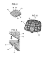
- the cover 60 is shown in figure 5 .
- the cover 60 has been also illustrated in the perspectigve view of the mirror assembly 100 shown in figure 1 .
- the cover 60 is configured as a housing for receiving the carrying element 20 and the mirror pane 10.
- the supporting means 61 act as structural elements for reinforcing the mirror pane carrying element 20 and for reinforcing the mirror pane 10 when assembled therein.
- the supporting means 61 comprise a number of supporting elements 65 formed on an inner surface 62 of the cover 60.
- the supporting elements 65 are walls arranged such that they extend perpendicular to the inner surface 62 of the mirror pane 10 towards the mirror pane 10 in the assembled condition.
- the first clipping means 30 comprise a plurality of flanges 31. As shown in figure 2 the plurality of flanges 31 are formed in a peripheral portion 32 of the mirror pane 10. The flanges 31 may be in the form of hooks designed for enhancing attachment of the mirror pane 10 to the carrying element 20.
- the flanges 31 or hooks could be formed on a central portion 35 of the mirror pane 10.
- the plurality of flanges 31 in the mirror pane 10 are intended to be received into corresponding openings 33 formed on a corresponding portion of the carrying element 20, that is, in a peripheral portion 32 and/or a central portion 35 of the carrying element 20.
- the first clipping means 30 defined by the flanges 31 of the mirror pane 10 and the openings 33 of the carrying element 20 serve the purpose of coupling of the mirror pane 10 with the carrying element 20.
- the above coupling function is of course also possible by providing the plurality of flanges 31 on a peripheral portion 32 and/or a central portion 35 of the carrying element 20 and with the openings 33 formed on a peripheral portion 34 and/or a central portion 36 of the mirror pane 10.
- the openings 33 are formed in a plane substantially perpendicular to that of the flanges 31, as clearly shown in figure 6 .
- the openings 33 are formed in a peripheral portion 32 of the carrying element 20 and have a substantially U configuration, open at one side thereof.
- This embodiment is preferred as it allows removal of the flange 31 from the opening 33 to be facilitated and its manufacturing process is easy since the demoulding step is facilitated.
- This U shaped configuration of the openings 33 a single step is only required for the assembly operation of the mirror pane 10 in the mirror pane carrying element 20 with a reduced play in use.
- the openings 33 may have a closed configuration in view of enhancing robustness
- the flange 31 includes a ramp 37.
- the ramp 37 in each flange 31 is designed to facilitate coupling the mirror pane 10 to the carrying element 20, that is, to facilitate insertion of the flange 31 into the corresponding opening 33.
- the ramp 37 in each flange 31 may be formed in one, in some or of in all of the flanges 31.
- the ramp 37 may be formed of a single ramp of it may comprise a number of sub-ramps.
- the first clipping means 30 further comprise a plurality of pressure tabs 38 arranged in correspondence with the openings 33 of the carrying element 20.
- the pressure tabs 38 abut the corresponding flanges 31.
- the carrying element 20 is attached to the cover 60 through second clipping means.
- These second clipping means comprises a number of flanges that may be formed on a peripheral portion of the carrying element 20. However, alternatively or additionally, the flanges could be formed on a peripheral portion of the cover 60.
- the second clipping means also comprises openings formed in a peripheral portion of the carrying element 20 although, according to the above, they could be formed in a peripheral portion of the cover 60.
- the carrying element 20 has a plurality of protruding areas 40, 41.
- the plurality of protruding areas 40,4 1 consists in this specific example of four substantially rectangular peripheral protruding areas 40 formed in the peripheral portion 32 of the carrying element 20 and an additional central circular protruding area 41 formed in the central portion 35 of the carrying element 20.
- corresponding double-sided adhesive pads 45 are provided.
- the adhesive pads 45 serve the purpose of attaching the mirror pane 10 with the carrying element 20 together.
Abstract
Description
- The present disclosure relates to mirror assemblies for motor vehicles and specifically to improved means for attaching internal parts in a rear view assembly for a motor vehicle or the like.
- Rear view mirror assemblies currently comprise a support structure also referred to as frame and a mirror element comprising a thin substrate or mirror pane, which may be made, for example, of glass. The mirror pane generally has a first reflective surface.
- More recently, in rear view mirror assemblies the mirror pane is made of plastic material coated with at least one thin reflective layer on a first surface. Plastic based mirror panes have significant advantages over conventional glass based mirror panes. The former are significantly lighter and more cost effective than the latter. In addition, plastic mirror panes have an increased resistance to temperature changes and a good impact resistance as compared to glass based mirror panes. A further significant advantage in plastic based mirror panes is that the manufacture of the mirror pane is more flexible, such that large variety of forms can be made specifically with a wide range of curvatures, and with virtually any irregular surface being possible to be formed.
- In such types of mirror assemblies where the mirror pane comprises a substrate made of plastic material coated with at least one thin reflective layer on the first surface, attaching of the mirror pane to the support structure is a delicate operation. It has been found that current ways of attaching the mirror pane to the support structure involves complexity and costs.
- Document
US2009213481 discloses a mirror assembly for motor vehicles comprising a housing having an opening and a mirror secured to the housing at the opening. The mirror is a unitary structure having a periphery and a flange extending around a portion of the periphery. The flange is adapted to be received into a channel formed in the periphery of a backing plate.EP2457770 provides a mirror assembly comprising a mirror pane made of plastic material coated with at least one reflective layer on a first surface. The mirror pane has three or more clips for attaching to a support structure on a second surface of the mirror pane. The clips are configured such that they have at least one shoulder for increasing the contact area between the clip and the second surface. -
EP0864465 refers to a mirror assembly having a reflective member moulded from plastics material attached to a support structure. The reflective member has a front surface with reflective coating and a rear surface with lugs having a ramp face leading to a detent edge. Lugs are intended to snap fit over a circular disk formed on an end of a support pillar which projects within a mirror case. - Notwithstanding the variety of solutions existing in the prior art for attaching parts in a rear view assembly there is still a need for a low cost, simple and effective means for attaching parts in a rear view assembly for motor vehicles.
- A rear view mirror assembly for motor vehicles as defined in claim 1 is provided herein with which the above need is met. In addition, it has been found that the present rear view mirror assembly according to claim 1 provides further advantages. Preferred embodiments are defined in the dependent claims.
- The present rear view mirror assembly comprises a mirror pane that can be made of plastic materials such as polycarbonate (PC), polymethyl methacrylate (PMMA), plastic polymers such as allyl diglycol carbonate (ADC) CR-39, or similar materials. Such materials are selected as they are lighter than glass, have higher impact resistance and are more resistant to changes in temperature. The mirror pane may have a variable thickness cross-section. In one example, the mirror pane may be of the order of 1.2- 2.0 mm thick. Other similar materials and configurations are not ruled out within the meaning of this disclosure.
- The present mirror pane has a first surface and a second surface. One of the surfaces of the mirror pane (first surface) may be coated with at least one thin reflective layer. In this respect, the mirror pane may be provided, for example, with at least one metallized surface. In some cases, the mirror pane could also include means for avoiding blurring of the reflected image.
- In the present case, it is preferred that the present mirror pane is made of a single piece, obtained for example through an injection moulding process. This process allows mirror panes with high visual properties having different thickness to be easily obtained, even mirror panes with very thin thicknesses and with a wide range of diameters and shapes defining irregular surfaces.
- A carrying element is provided for carrying the mirror pane. The carrying element may be, e.g., a backplate or frame made of a plastic material suitable for carrying the mirror pane. The carrying element may be made of a single piece, obtained for example through an injection moulding process.
- The carrying element may be provided with a number of slots for receiving corresponding ribs formed in the mirror pane. Said ribs formed in the mirror pane may perform a reinforcing function of the mirror pane.
- The slots may be formed in one or more portions of the carrying element. Said portions of the carrying element may be selected from at least one of a central portion and a peripheral portion of the carrying element.
- The present rear view mirror assembly also comprises a cover. The cover is defined as a housing designed for at least partially receiving the carrying element with the mirror pane.
- Supporting means are further provided formed in or associated with the cover. The supporting means comprise a number of supporting elements. The supporting elements extending from an inner surface of the cover towards an inner surface of the mirror pane to abut the inner surface of the mirror pane.
- Therefore, supporting means are structural elements formed of supporting elements as stated above, for reinforcing the mirror pane carrying element. However, the supporting means serves also the purpose of reinforcing the mirror pane when it is assembled into the carrying element. This is important since the mirror pane is typically flexible for adapting to variable curvatures. The structural and reinforcing functions of the supporting means also ensure a good performance in terms of reducing image distortion and good mechanical behaviour of the mirror assembly.
- In some embodiments, first clipping means may be provided. The first clipping means are designed for coupling the mirror pane and the carrying element together. In one example, the first clipping means may comprise at least one flange, a preferably a number of flanges. The flange or flanges may be in the form of hooks formed in the mirror pane. The hooks are suitably sized and shaped to enhance attachment of the mirror pane to the carrying element. The anchoring hooks of the mirror pane are shaped to engage a corresponding coupling portion of the carrying element.
- This flange or flanges may be formed on a peripheral portion defined in at least one of the mirror pane and the carrying element. At least one corresponding opening is formed in a peripheral portion of the other of at least the mirror pane and the carrying element. The openings are adapted for receiving the flange or flanges. The openings are formed in a plane that is substantially perpendicular to that of the flange.
- In some specific cases of the present rear view mirror assembly, the openings formed in a peripheral portion of the mirror pane and/or the carrying element may have a substantially U configuration, open at one side thereof. This particular U shaped configuration of the openings allows removal of the flange from the corresponding opening to be facilitated. Such U shaped configuration of the openings is also advantageous in the manufacturing process of the rear view mirror assembly since demoulding of the flanges is facilitated. Furthermore, a single step is only required for the assembly operation of the mirror pane in the mirror pane carrying element. This involves a great improvement over the four-step assembly operation required in the prior art mirror assemblies which involves at least preparing and heating an adhesive, placing the adhesive onto the mirror pane, fitting the mirror pane into the carrying element and pressing the sub-assembly. In addition, with this particular U shaped configuration of the openings there is a reduced play between the flanges and the corresponding openings. This also helps in facilitating assemblying operations.
- As an alternative, the openings may have a closed configuration. This particular closed configuration of the openings is advantageous as it enhances robustness. The closed configuration of the openings further enhances the mechanical properties of the assembly rendering it stronger while also helping in facilitating assembly.
- A least one of the flange and the opening may include at least one ramp. The ramps are suitably designed to facilitate coupling the mirror pane and the carrying element together in an easy way.
- The clipping means may further comprise at least one pressure tab, but preferably a number of pressure tabs arranged in correspondence with the openings. In use, the pressure tabs abut the respective flanges. This ensure a correct coupling of the mirror pane with the carrying element.
- The above mentioned first clipping means may be formed in a final design step. This involves that they do not need to be arranged at specific points of the geometry but in any part thereof.
- The configuration of the outer contour of the mirror pane carrying element and the housing match each other. This provides the mirror assembly with a good appearance. No gaps are visible between the parts so aerodynamics is also enhanced. Therefore, the mirror pane and the carrying element form a monoblock element. This feature also facilitates the mirror assembly to be assembled on a mirror actuator.
- The carrying element may be provided with at least one protruding area, with a number of protruding areas being preferred. The protruding areas in the carrying element may be formed in one or more portions selected from a central and a peripheral portion of the cover.
- A number of adhesive pads may be provided in correspondence with said protruding areas of the carrying element. These adhesive pads may be double-sided adhesive pads of any shape as long as they have good adhesive properties and enough thickness for attachment of the mirror pane with the mirror pane carrying element together with the cover. According to a very specific embodiment of the present mirror assembly, a set of five adhesive pads is used, with four being rectangular in shape while the remainder being circular in shape. Other configurations, shapes, number and distribution of the adhesive pads are however not ruled out. In one example of the adhesive pads, they may be double-sided adhesive pads made of polyurethane (PUR) or polyethylene (PE).
- The present rear view mirror assembly may further comprise second clipping means for coupling the carrying element with the cover together. The second clipping means may comprise at least one flange formed on a peripheral portion of at least one of the carrying element and the cover. The second clipping means may further comprise at least one corresponding opening formed in a peripheral portion of the other of at least the carrying element and the cover.
- Any of the parts involved in the present rear view mirror assembly may be made by an injection moulding process. In some cases or for some specific parts of the present a rear view mirror assembly, an injection compression moulding process could be used for their manufacture.
- Additional objects, advantages and features of embodiments of the present rear view mirror assembly for motor vehicles will become apparent to those skilled in the art upon examination of the description, or may be learned by practice thereof.
- A particular non-limiting example of the present rear view mirror assembly for motor vehicles will be described in the following in more detail and with reference to the appended drawings.
- In the drawings:
-
Figure 1 is a perspective view of one embodiment of the present rear view mirror assembly for motor vehicles; -
Figure 2 is a perspective view of one embodiment of the mirror pane in the mirror assembly shown infigure 1 ; -
Figure 3 is a perspective view of one embodiment of the carrying element of the mirror assembly shown infigure 1 ; -
Figure 4 is a perspective view of the mirror pane shown infigure 2 attached to the carrying element shown infigure 3 as part of the rear view mirror assembly shown infigure 1 ; -
Figure 5 is a perspective view of one embodiment of a cover of the mirror assembly shown infigure 1 ; and -
Figure 6 is a perspective part view of pane shown separated from the carrying element shown to shown the first clipping means. - The specific example shown in the
figures 1 - 6 corresponds to one possible embodiment of the present rear view mirror assembly, which has been indicated as a whole at 100. Themirror assembly 100 mainly comprises amirror pane 10, a mirrorpane carrying element 20 and acover 60. - The
mirror pane 10 is infigure 2 . It is formed of a plastics single piece obtained through an injection moulding process. Themirror pane 10 is made of a suitable plastic material such as polymethyl methacrylate (PMMA), polycarbonate (PC) of allyl diglycol carbonate (ADC) CR-39 due to their improved propierties over glass, for example. In this example, themirror pane 10 is a variable thickness laminar element, such as for example 1.2- 2.0 mm thick. One of the surfaces of themirror pane 10 is coated with at least one thin reflective layer, i.e. a metallized surface. - The mirror
pane carrying element 20 is infigure 3 . The carryingelement 20 is a backplate or frame suitably sized and shaped for carrying themirror pane 10 as shown infigure 4 . As with themirror pane 10, the carryingelement 20 is formed of a single piece made of a plastic material obtained through an injection moulding process. - As shown in
figure 3 of the drawings, the carryingelement 20 is provided with a number ofslots 50. Theseslots 50 are adapted, in terms of thickess, length, height, position, number, etc, for receivingcorresponding ribs 16 formed in themirror pane 10 which will be described below. Theslots 50 of the carryingelement 20 may be formed in one or more portions of the carryingelement 20. In the example shown infigure 3 , theslots 50 of the carryingelement 20 are formed in acentral portion 35 thereof. However, theslots 50 of the carryingelement 20 could be alternatively or additionally in aperipheral portion 32 thereof, depending on where thecorresponding ribs 16 are formed in themirror pane 10, that is, in its central portion 36 (as shown in the embodiment offigure 3 ) and/or in itsperipheral portion 34. - In general, the
ribs 16 of themirror pane 10 consist of portions projecting from aninner surface 12 of themirror pane 10. Theribs 16 of themirror pane 10 may be configured in a number of different ways selected from one or more of diametrical cross-shaped ribs 12 (as shown infigure 2 ); central pins; central bosses; central or perimetral portions (e.g. circular portions) with variable thickness; bottom clips (e.g. pairs of parallel clips projecting from the inner surface of the mirror pane 10) which could be designed to match a slider mechanism for suitable attachment of themirror pane 10; perimetral windows and combinations thereof. Such different embodiments of theribs 16 of themirror pane 10 can be obtained through a molding process. The thickness of theribs 16 in any of the above specific examples would be a function of themirror pane 10 thickness. In the preferred embodiment, themirror pane 10 is provided with center ribs 16 (as shown infigure 2 ) to stiffen purposes on that area together with additional perimetral ribs 16 (not shown) to increase stiffness. - One embodiment of the
cover 60 is shown infigure 5 . Thecover 60 has been also illustrated in the perspectigve view of themirror assembly 100 shown infigure 1 . Thecover 60 is configured as a housing for receiving the carryingelement 20 and themirror pane 10. Associated both with the carryingelement 20 and thecover 10 are supportingmeans 61. The supporting means 61 act as structural elements for reinforcing the mirrorpane carrying element 20 and for reinforcing themirror pane 10 when assembled therein. As shown infigure 5 of the drawings, the supportingmeans 61 comprise a number of supportingelements 65 formed on aninner surface 62 of thecover 60. In the embodiment shown infigure 5 , the supportingelements 65 are walls arranged such that they extend perpendicular to theinner surface 62 of themirror pane 10 towards themirror pane 10 in the assembled condition. - Associated both with the
mirror pane 10 and the carryingelement 20 are first clipping means 30. The first clipping means 30 comprise a plurality offlanges 31. As shown infigure 2 the plurality offlanges 31 are formed in aperipheral portion 32 of themirror pane 10. Theflanges 31 may be in the form of hooks designed for enhancing attachment of themirror pane 10 to the carryingelement 20. - Alternatively or additionally the
flanges 31 or hooks could be formed on acentral portion 35 of themirror pane 10. The plurality offlanges 31 in themirror pane 10 are intended to be received into correspondingopenings 33 formed on a corresponding portion of the carryingelement 20, that is, in aperipheral portion 32 and/or acentral portion 35 of the carryingelement 20. - The first clipping means 30 defined by the
flanges 31 of themirror pane 10 and theopenings 33 of the carryingelement 20 serve the purpose of coupling of themirror pane 10 with the carryingelement 20. - The above coupling function is of course also possible by providing the plurality of
flanges 31 on aperipheral portion 32 and/or acentral portion 35 of the carryingelement 20 and with theopenings 33 formed on aperipheral portion 34 and/or acentral portion 36 of themirror pane 10. - In any case, the
openings 33 are formed in a plane substantially perpendicular to that of theflanges 31, as clearly shown infigure 6 . - In the embodiment shown in
figures 3 ,4 and 6 , theopenings 33 are formed in aperipheral portion 32 of the carryingelement 20 and have a substantially U configuration, open at one side thereof. This embodiment is preferred as it allows removal of theflange 31 from theopening 33 to be facilitated and its manufacturing process is easy since the demoulding step is facilitated. With this U shaped configuration of theopenings 33, a single step is only required for the assembly operation of themirror pane 10 in the mirrorpane carrying element 20 with a reduced play in use. - However, other configurations of the
openings 33 are possible. For example, theopenings 33 may have a closed configuration in view of enhancing robustness - As shown in
figure 6 , theflange 31 includes a ramp 37. The ramp 37 in eachflange 31 is designed to facilitate coupling themirror pane 10 to the carryingelement 20, that is, to facilitate insertion of theflange 31 into thecorresponding opening 33. The ramp 37 in eachflange 31 may be formed in one, in some or of in all of theflanges 31. The ramp 37 may be formed of a single ramp of it may comprise a number of sub-ramps. - According to
figure 3 , the first clipping means 30 further comprise a plurality of pressure tabs 38 arranged in correspondence with theopenings 33 of the carryingelement 20. In use, that is with themirror pane 10 fitted to the carryingelement 20, the pressure tabs 38 abut the correspondingflanges 31. - Although not shown in the figures, the carrying
element 20 is attached to thecover 60 through second clipping means. These second clipping means comprises a number of flanges that may be formed on a peripheral portion of the carryingelement 20. However, alternatively or additionally, the flanges could be formed on a peripheral portion of thecover 60. The second clipping means also comprises openings formed in a peripheral portion of the carryingelement 20 although, according to the above, they could be formed in a peripheral portion of thecover 60. - The following is a further embodiment for attaching of the elements in the present mirror assembly which may be used alone or in combination with the above mentioned embodiments.
- In the particularly preferred embodiment shown in the
figure 3 , the carryingelement 20 has a plurality of protrudingareas areas 40,4 1 consists in this specific example of four substantially rectangular peripheral protrudingareas 40 formed in theperipheral portion 32 of the carryingelement 20 and an additional central circular protrudingarea 41 formed in thecentral portion 35 of the carryingelement 20. - In correspondence with the protruding
areas element 20, corresponding double-sidedadhesive pads 45 are provided. Theadhesive pads 45 serve the purpose of attaching themirror pane 10 with the carryingelement 20 together. - Although only a number of particular embodiments and examples of the present rear view mirror assembly for motor vehicles have been disclosed herein, it will be understood by those skilled in the art that other alternative embodiments, uses and obvious modifications and equivalents thereof are possible. Furthermore, the present disclosure covers all possible combinations of the particular embodiments described.
- The scope of the present disclosure should therefore not be limited by particular the embodiment herein disclosed, but should be determined only by a fair reading of the claims that follow
- Reference signs related to drawings and placed in parentheses in a claim, are solely for attempting to increase the intelligibility of the claim, and shall not be construed as limiting the scope of the claim.
Claims (18)
- - Rear view mirror assembly (100) for motor vehicles, comprising:- a mirror pane (10);- a mirror pane carrying element (20);- a cover (60) for at least partially receiving the carrying element (20) with the mirror pane (10); and- supporting means (61) formed the cover (60),wherein the supporting means (61) comprise a number of supporting elements (65) formed on an inner surface (62) of the cover (60), the supporting elements (65) extending to abut an inner surface (12) of the mirror pane (10).
- - Rear view mirror assembly (100) as claimed in claim 1, wherein a series of ribs (16) are provided in one or more portions of the mirror pane (10) selected from a central portion (36) and a peripheral portion (34) of the mirror pane (10).
- - Rear view mirror assembly (100) as claimed in claim 2, wherein the carrying element (20) is provided with a number of slots (50) formed in one or more portions of the carrying element (20) selected from a central portion (35) and a peripheral portion (32) of the carrying element (20) for receiving the mirror pane ribs (16).
- - Rear view mirror assembly (100) as claimed in any of the preceding claims, wherein it further comprises first clipping means (30) for coupling the mirror pane (10) and the carrying element (20) together.
- - Rear view mirror assembly (100) as claimed in claim 4, wherein the first clipping means (30) comprise at least one flange (31) formed on a peripheral portion (32; 34) of at least one of the mirror pane (10) and the carrying element (20); and at least one opening (33) formed in a peripheral portion (34; 32) of the other of at least the mirror pane (10) and the carrying element (20) adapted for receiving the flange (31), with the opening (33) being formed in a plane substantially perpendicular to that of the flange (31).
- - Rear view mirror assembly (100) as claimed in claim 5, wherein the opening (33) has a substantially U configuration, open at one side thereof to facilitate removal of the flange (31) from the corresponding opening (33).
- - Rear view mirror assembly (100) as claimed in claim 5 or claim 6, wherein the opening (33) has a closed configuration to enhance robustness.
- - Rear view mirror assembly (100) as claimed in any of the claims 5-7, wherein at least one of the flange (31) and the opening (33) includes at least one ramp (37) to facilitate insertion of the flange (31) into the corresponding opening (33).
- - Rear view mirror assembly (100) as claimed in any of the claims 4-8, wherein the first clipping means (30) further comprise pressure tabs (38) arranged in correspondence with the openings (33) such that, in use, the pressure tabs (38) abut the respective flanges (31).
- - Rear view mirror assembly (100) as claimed in any of the claims 4-9, wherein the flanges (31) are in the form of anchoring hooks formed in the mirror pane (10) for attachment to the carrying element (20).
- - Rear view mirror assembly (100) as claimed in any of the preceding claims, wherein the mirror pane (10) has a variable thickness cross-section.
- - Rear view mirror assembly (100) as claimed in any of the preceding claims, wherein the cover (60) is provided with at least one protruding area (40, 41) formed in one or more portions selected from a central (35) and a peripheral portion (32) of the cover (60).
- - Rear view mirror assembly (100) as claimed in claim 12, wherein at least one adhesive pad (45) is provided in correspondence with at least one of said protruding areas (40, 41).
- - Rear view mirror assembly (100) as claimed in any of the preceding claims, wherein at least one of the mirror pane (10) and the carrying element (20) is made of plastic.
- - Rear view mirror assembly (100) as claimed in any of the preceding claims, wherein the mirror pane (10) has at least one metallized surface (15).
- - Rear view mirror assembly (100) as claimed in any of the preceding claims, wherein at least one of the mirror pane (10) and the carrying element (20) is made of a single piece.
- - Rear view mirror assembly (100) as claimed in any of the preceding claims, wherein at least one of the mirror pane (10) and the carrying element (20) is made by an injection moulding process.
- - Rear view mirror assembly (100) as claimed in any of the preceding claims, wherein it further comprises second clipping means for coupling the carrying element (20) with the cover (60) together; the second clipping means comprising at least one flange formed on a peripheral portion of at least one of the carrying element (20) and the cover (60); and at least one opening formed in a peripheral portion of the other of at least the carrying element (20) and the cover (60).
Priority Applications (3)
| Application Number | Priority Date | Filing Date | Title |
|---|---|---|---|
| EP13175190.1A EP2821284B1 (en) | 2013-07-04 | 2013-07-04 | Rear view mirror assembly for motor vehicles |
| CN201410288875.6A CN104276090B (en) | 2013-07-04 | 2014-06-24 | Rearview mirror assemblies for motor vehicles |
| US14/317,947 US9393909B2 (en) | 2013-07-04 | 2014-06-27 | Rear view mirror assembly for motor vehicles |
Applications Claiming Priority (1)
| Application Number | Priority Date | Filing Date | Title |
|---|---|---|---|
| EP13175190.1A EP2821284B1 (en) | 2013-07-04 | 2013-07-04 | Rear view mirror assembly for motor vehicles |
Publications (2)
| Publication Number | Publication Date |
|---|---|
| EP2821284A1 true EP2821284A1 (en) | 2015-01-07 |
| EP2821284B1 EP2821284B1 (en) | 2018-03-07 |
Family
ID=48745803
Family Applications (1)
| Application Number | Title | Priority Date | Filing Date |
|---|---|---|---|
| EP13175190.1A Active EP2821284B1 (en) | 2013-07-04 | 2013-07-04 | Rear view mirror assembly for motor vehicles |
Country Status (3)
| Country | Link |
|---|---|
| US (1) | US9393909B2 (en) |
| EP (1) | EP2821284B1 (en) |
| CN (1) | CN104276090B (en) |
Families Citing this family (5)
| Publication number | Priority date | Publication date | Assignee | Title |
|---|---|---|---|---|
| CN105329355A (en) * | 2015-10-28 | 2016-02-17 | 无锡尊宝电动车有限公司 | Breakage-proof electric bicycle rearview mirror with double surfaces |
| CN105329363A (en) * | 2015-10-28 | 2016-02-17 | 无锡尊宝电动车有限公司 | Novel electric vehicle rear-view mirror |
| CN105329356A (en) * | 2015-10-28 | 2016-02-17 | 无锡尊宝电动车有限公司 | Composite and drop-resistant electrocar rearview mirror |
| JP6998406B2 (en) * | 2017-06-30 | 2022-01-18 | エスエムアール・パテンツ・ソシエテ・ア・レスポンサビリテ・リミテ | An assembly, a method for assembling the assembly, a method for disassembling the assembly, an external rear visual device with the assembly and a motor vehicle with the rear visual device. |
| CN111212758B (en) * | 2017-11-09 | 2023-09-01 | 沃尔沃卡车集团 | Rearview mirror assembly for vehicle |
Citations (5)
| Publication number | Priority date | Publication date | Assignee | Title |
|---|---|---|---|---|
| EP0864465A2 (en) | 1997-03-15 | 1998-09-16 | Britax (Geco) S.A. | Vehicle rear view mirror |
| ES2186514A1 (en) * | 2001-01-05 | 2003-05-01 | Fico Mirrors Sa | Fixing device for car rear-view mirrors. |
| WO2006014209A2 (en) * | 2004-06-08 | 2006-02-09 | Gentex Corporation | Rearview assembly having an integral crush zone |
| US20090213481A1 (en) | 2007-09-14 | 2009-08-27 | Visiocorp Patents S.A.R.L | Side mirror assembly with integrated spotting mirror |
| EP2457770A1 (en) | 2010-11-29 | 2012-05-30 | SMR Patents S.à.r.l. | Plastic glass mounting and retention device |
Family Cites Families (10)
| Publication number | Priority date | Publication date | Assignee | Title |
|---|---|---|---|---|
| US3874773A (en) * | 1973-09-24 | 1975-04-01 | Donnelly Mirrors Inc | Mirror case with expansion-absorbing means |
| DE2431047A1 (en) * | 1974-06-27 | 1976-01-08 | Thermoplast & Apparatebau Gmbh | Rear view mirror with protective hard glass layer - providing distortion-free image without danger and with reduced cost |
| US4029399A (en) | 1976-02-19 | 1977-06-14 | Ernest Haile | Frame for convex mirror |
| US6176602B1 (en) | 1993-02-01 | 2001-01-23 | Donnelly Corporation | Vehicle exterior mirror system with signal light |
| US5721646A (en) * | 1996-02-23 | 1998-02-24 | Kam Truck Components, Inc. | Exterior rearview mirror for vehicles |
| US6064509A (en) | 1997-08-22 | 2000-05-16 | Gentex Corporation | Clip for use with transparent conductive electrodes in electrochromic devices |
| AU2003228639A1 (en) * | 2002-04-23 | 2003-11-10 | Magna Donnelly Mirrors North America, L.L.C. | Vehicle mirror having polymeric reflective film element and self-dimming element |
| WO2003105099A1 (en) * | 2002-06-06 | 2003-12-18 | Donnelly Corporation | Interior rearview mirror system with compass |
| JP4321367B2 (en) * | 2004-06-10 | 2009-08-26 | 市光工業株式会社 | Outside mirror device for vehicle |
| DE102008046981B4 (en) * | 2008-09-12 | 2010-12-02 | Mekra Lang Gmbh & Co. Kg | mirror element |
-
2013
- 2013-07-04 EP EP13175190.1A patent/EP2821284B1/en active Active
-
2014
- 2014-06-24 CN CN201410288875.6A patent/CN104276090B/en active Active
- 2014-06-27 US US14/317,947 patent/US9393909B2/en active Active
Patent Citations (5)
| Publication number | Priority date | Publication date | Assignee | Title |
|---|---|---|---|---|
| EP0864465A2 (en) | 1997-03-15 | 1998-09-16 | Britax (Geco) S.A. | Vehicle rear view mirror |
| ES2186514A1 (en) * | 2001-01-05 | 2003-05-01 | Fico Mirrors Sa | Fixing device for car rear-view mirrors. |
| WO2006014209A2 (en) * | 2004-06-08 | 2006-02-09 | Gentex Corporation | Rearview assembly having an integral crush zone |
| US20090213481A1 (en) | 2007-09-14 | 2009-08-27 | Visiocorp Patents S.A.R.L | Side mirror assembly with integrated spotting mirror |
| EP2457770A1 (en) | 2010-11-29 | 2012-05-30 | SMR Patents S.à.r.l. | Plastic glass mounting and retention device |
Also Published As
| Publication number | Publication date |
|---|---|
| CN104276090A (en) | 2015-01-14 |
| US9393909B2 (en) | 2016-07-19 |
| CN104276090B (en) | 2018-08-28 |
| EP2821284B1 (en) | 2018-03-07 |
| US20150008692A1 (en) | 2015-01-08 |
Similar Documents
| Publication | Publication Date | Title |
|---|---|---|
| US9393909B2 (en) | Rear view mirror assembly for motor vehicles | |
| KR100892694B1 (en) | Door frame for vehicle | |
| JP6051070B2 (en) | Vehicle window member fixing structure | |
| CN111527009A (en) | Radar-transparent decorative panel for a front grille of a motor vehicle | |
| US7857469B2 (en) | Exterior rearview mirror for motor vehicles | |
| JP4621808B1 (en) | Plastic clip | |
| JP5518989B2 (en) | Vehicle door | |
| JP2014091342A (en) | Vehicle resin glass | |
| CN217259842U (en) | Seamless integrated laser radar's of inserts formula of moulding plastics car gadget | |
| JP2022185067A (en) | Exterior applique with interchangeable inserts | |
| US20140177041A1 (en) | Outside mirror assembly for vehicle | |
| US9081539B2 (en) | Holding mechanism for display device and assembling method of the same | |
| JP2012171392A (en) | Resin glass for automobile | |
| JP2013248911A (en) | Plate-like body for vehicle window with framework and assembling method thereof | |
| JP2016052896A (en) | Vehicle window plate with frame and assembling method of vehicle window plate with frame | |
| JP6514906B2 (en) | Long fins for register | |
| JP5875873B2 (en) | Mirror device | |
| US20130208374A1 (en) | Holder attached mirror for vehicle | |
| JP6480743B2 (en) | Mirror holder structure for vehicles | |
| JP2017178015A (en) | Transparent member, radar cover, and manufacturing method of radar cover | |
| JPH0636976Y2 (en) | Window molding | |
| EP4329093A1 (en) | Emblem for vehicle with built-in heater, and manufacturing method thereof | |
| JP5330561B2 (en) | Automotive visor | |
| JP2012140062A (en) | Interior and exterior for automobile | |
| CN107499250B (en) | Vehicle with a steering wheel |
Legal Events
| Date | Code | Title | Description |
|---|---|---|---|
| PUAI | Public reference made under article 153(3) epc to a published international application that has entered the european phase |
Free format text: ORIGINAL CODE: 0009012 |
|
| 17P | Request for examination filed |
Effective date: 20130704 |
|
| AK | Designated contracting states |
Kind code of ref document: A1 Designated state(s): AL AT BE BG CH CY CZ DE DK EE ES FI FR GB GR HR HU IE IS IT LI LT LU LV MC MK MT NL NO PL PT RO RS SE SI SK SM TR |
|
| AX | Request for extension of the european patent |
Extension state: BA ME |
|
| R17P | Request for examination filed (corrected) |
Effective date: 20150707 |
|
| RBV | Designated contracting states (corrected) |
Designated state(s): AL AT BE BG CH CY CZ DE DK EE ES FI FR GB GR HR HU IE IS IT LI LT LU LV MC MK MT NL NO PL PT RO RS SE SI SK SM TR |
|
| 17Q | First examination report despatched |
Effective date: 20151104 |
|
| GRAP | Despatch of communication of intention to grant a patent |
Free format text: ORIGINAL CODE: EPIDOSNIGR1 |
|
| INTG | Intention to grant announced |
Effective date: 20170926 |
|
| GRAS | Grant fee paid |
Free format text: ORIGINAL CODE: EPIDOSNIGR3 |
|
| GRAA | (expected) grant |
Free format text: ORIGINAL CODE: 0009210 |
|
| AK | Designated contracting states |
Kind code of ref document: B1 Designated state(s): AL AT BE BG CH CY CZ DE DK EE ES FI FR GB GR HR HU IE IS IT LI LT LU LV MC MK MT NL NO PL PT RO RS SE SI SK SM TR |
|
| REG | Reference to a national code |
Ref country code: GB Ref legal event code: FG4D |
|
| REG | Reference to a national code |
Ref country code: CH Ref legal event code: EP Ref country code: AT Ref legal event code: REF Ref document number: 976192 Country of ref document: AT Kind code of ref document: T Effective date: 20180315 |
|
| REG | Reference to a national code |
Ref country code: IE Ref legal event code: FG4D |
|
| REG | Reference to a national code |
Ref country code: DE Ref legal event code: R096 Ref document number: 602013033947 Country of ref document: DE |
|
| REG | Reference to a national code |
Ref country code: NL Ref legal event code: MP Effective date: 20180307 |
|
| REG | Reference to a national code |
Ref country code: LT Ref legal event code: MG4D |
|
| REG | Reference to a national code |
Ref country code: FR Ref legal event code: PLFP Year of fee payment: 6 |
|
| PG25 | Lapsed in a contracting state [announced via postgrant information from national office to epo] |
Ref country code: FI Free format text: LAPSE BECAUSE OF FAILURE TO SUBMIT A TRANSLATION OF THE DESCRIPTION OR TO PAY THE FEE WITHIN THE PRESCRIBED TIME-LIMIT Effective date: 20180307 Ref country code: CY Free format text: LAPSE BECAUSE OF FAILURE TO SUBMIT A TRANSLATION OF THE DESCRIPTION OR TO PAY THE FEE WITHIN THE PRESCRIBED TIME-LIMIT Effective date: 20180307 Ref country code: NO Free format text: LAPSE BECAUSE OF FAILURE TO SUBMIT A TRANSLATION OF THE DESCRIPTION OR TO PAY THE FEE WITHIN THE PRESCRIBED TIME-LIMIT Effective date: 20180607 Ref country code: ES Free format text: LAPSE BECAUSE OF FAILURE TO SUBMIT A TRANSLATION OF THE DESCRIPTION OR TO PAY THE FEE WITHIN THE PRESCRIBED TIME-LIMIT Effective date: 20180307 Ref country code: HR Free format text: LAPSE BECAUSE OF FAILURE TO SUBMIT A TRANSLATION OF THE DESCRIPTION OR TO PAY THE FEE WITHIN THE PRESCRIBED TIME-LIMIT Effective date: 20180307 Ref country code: LT Free format text: LAPSE BECAUSE OF FAILURE TO SUBMIT A TRANSLATION OF THE DESCRIPTION OR TO PAY THE FEE WITHIN THE PRESCRIBED TIME-LIMIT Effective date: 20180307 |
|
| REG | Reference to a national code |
Ref country code: AT Ref legal event code: MK05 Ref document number: 976192 Country of ref document: AT Kind code of ref document: T Effective date: 20180307 |
|
| PG25 | Lapsed in a contracting state [announced via postgrant information from national office to epo] |
Ref country code: SE Free format text: LAPSE BECAUSE OF FAILURE TO SUBMIT A TRANSLATION OF THE DESCRIPTION OR TO PAY THE FEE WITHIN THE PRESCRIBED TIME-LIMIT Effective date: 20180307 Ref country code: LV Free format text: LAPSE BECAUSE OF FAILURE TO SUBMIT A TRANSLATION OF THE DESCRIPTION OR TO PAY THE FEE WITHIN THE PRESCRIBED TIME-LIMIT Effective date: 20180307 Ref country code: BG Free format text: LAPSE BECAUSE OF FAILURE TO SUBMIT A TRANSLATION OF THE DESCRIPTION OR TO PAY THE FEE WITHIN THE PRESCRIBED TIME-LIMIT Effective date: 20180607 Ref country code: RS Free format text: LAPSE BECAUSE OF FAILURE TO SUBMIT A TRANSLATION OF THE DESCRIPTION OR TO PAY THE FEE WITHIN THE PRESCRIBED TIME-LIMIT Effective date: 20180307 Ref country code: GR Free format text: LAPSE BECAUSE OF FAILURE TO SUBMIT A TRANSLATION OF THE DESCRIPTION OR TO PAY THE FEE WITHIN THE PRESCRIBED TIME-LIMIT Effective date: 20180608 |
|
| PG25 | Lapsed in a contracting state [announced via postgrant information from national office to epo] |
Ref country code: PL Free format text: LAPSE BECAUSE OF FAILURE TO SUBMIT A TRANSLATION OF THE DESCRIPTION OR TO PAY THE FEE WITHIN THE PRESCRIBED TIME-LIMIT Effective date: 20180307 Ref country code: EE Free format text: LAPSE BECAUSE OF FAILURE TO SUBMIT A TRANSLATION OF THE DESCRIPTION OR TO PAY THE FEE WITHIN THE PRESCRIBED TIME-LIMIT Effective date: 20180307 Ref country code: NL Free format text: LAPSE BECAUSE OF FAILURE TO SUBMIT A TRANSLATION OF THE DESCRIPTION OR TO PAY THE FEE WITHIN THE PRESCRIBED TIME-LIMIT Effective date: 20180307 Ref country code: RO Free format text: LAPSE BECAUSE OF FAILURE TO SUBMIT A TRANSLATION OF THE DESCRIPTION OR TO PAY THE FEE WITHIN THE PRESCRIBED TIME-LIMIT Effective date: 20180307 Ref country code: IT Free format text: LAPSE BECAUSE OF FAILURE TO SUBMIT A TRANSLATION OF THE DESCRIPTION OR TO PAY THE FEE WITHIN THE PRESCRIBED TIME-LIMIT Effective date: 20180307 Ref country code: AL Free format text: LAPSE BECAUSE OF FAILURE TO SUBMIT A TRANSLATION OF THE DESCRIPTION OR TO PAY THE FEE WITHIN THE PRESCRIBED TIME-LIMIT Effective date: 20180307 |
|
| PG25 | Lapsed in a contracting state [announced via postgrant information from national office to epo] |
Ref country code: SK Free format text: LAPSE BECAUSE OF FAILURE TO SUBMIT A TRANSLATION OF THE DESCRIPTION OR TO PAY THE FEE WITHIN THE PRESCRIBED TIME-LIMIT Effective date: 20180307 Ref country code: AT Free format text: LAPSE BECAUSE OF FAILURE TO SUBMIT A TRANSLATION OF THE DESCRIPTION OR TO PAY THE FEE WITHIN THE PRESCRIBED TIME-LIMIT Effective date: 20180307 Ref country code: SM Free format text: LAPSE BECAUSE OF FAILURE TO SUBMIT A TRANSLATION OF THE DESCRIPTION OR TO PAY THE FEE WITHIN THE PRESCRIBED TIME-LIMIT Effective date: 20180307 Ref country code: CZ Free format text: LAPSE BECAUSE OF FAILURE TO SUBMIT A TRANSLATION OF THE DESCRIPTION OR TO PAY THE FEE WITHIN THE PRESCRIBED TIME-LIMIT Effective date: 20180307 |
|
| REG | Reference to a national code |
Ref country code: DE Ref legal event code: R097 Ref document number: 602013033947 Country of ref document: DE |
|
| PG25 | Lapsed in a contracting state [announced via postgrant information from national office to epo] |
Ref country code: PT Free format text: LAPSE BECAUSE OF FAILURE TO SUBMIT A TRANSLATION OF THE DESCRIPTION OR TO PAY THE FEE WITHIN THE PRESCRIBED TIME-LIMIT Effective date: 20180709 |
|
| PLBE | No opposition filed within time limit |
Free format text: ORIGINAL CODE: 0009261 |
|
| STAA | Information on the status of an ep patent application or granted ep patent |
Free format text: STATUS: NO OPPOSITION FILED WITHIN TIME LIMIT |
|
| PG25 | Lapsed in a contracting state [announced via postgrant information from national office to epo] |
Ref country code: DK Free format text: LAPSE BECAUSE OF FAILURE TO SUBMIT A TRANSLATION OF THE DESCRIPTION OR TO PAY THE FEE WITHIN THE PRESCRIBED TIME-LIMIT Effective date: 20180307 |
|
| 26N | No opposition filed |
Effective date: 20181210 |
|
| PG25 | Lapsed in a contracting state [announced via postgrant information from national office to epo] |
Ref country code: SI Free format text: LAPSE BECAUSE OF FAILURE TO SUBMIT A TRANSLATION OF THE DESCRIPTION OR TO PAY THE FEE WITHIN THE PRESCRIBED TIME-LIMIT Effective date: 20180307 |
|
| REG | Reference to a national code |
Ref country code: CH Ref legal event code: PL |
|
| GBPC | Gb: european patent ceased through non-payment of renewal fee |
Effective date: 20180704 |
|
| PG25 | Lapsed in a contracting state [announced via postgrant information from national office to epo] |
Ref country code: MC Free format text: LAPSE BECAUSE OF FAILURE TO SUBMIT A TRANSLATION OF THE DESCRIPTION OR TO PAY THE FEE WITHIN THE PRESCRIBED TIME-LIMIT Effective date: 20180307 Ref country code: LU Free format text: LAPSE BECAUSE OF NON-PAYMENT OF DUE FEES Effective date: 20180704 |
|
| REG | Reference to a national code |
Ref country code: BE Ref legal event code: MM Effective date: 20180731 |
|
| REG | Reference to a national code |
Ref country code: IE Ref legal event code: MM4A |
|
| PG25 | Lapsed in a contracting state [announced via postgrant information from national office to epo] |
Ref country code: CH Free format text: LAPSE BECAUSE OF NON-PAYMENT OF DUE FEES Effective date: 20180731 Ref country code: LI Free format text: LAPSE BECAUSE OF NON-PAYMENT OF DUE FEES Effective date: 20180731 Ref country code: IE Free format text: LAPSE BECAUSE OF NON-PAYMENT OF DUE FEES Effective date: 20180704 Ref country code: GB Free format text: LAPSE BECAUSE OF NON-PAYMENT OF DUE FEES Effective date: 20180704 |
|
| PG25 | Lapsed in a contracting state [announced via postgrant information from national office to epo] |
Ref country code: BE Free format text: LAPSE BECAUSE OF NON-PAYMENT OF DUE FEES Effective date: 20180731 |
|
| PGFP | Annual fee paid to national office [announced via postgrant information from national office to epo] |
Ref country code: FR Payment date: 20190731 Year of fee payment: 7 |
|
| PG25 | Lapsed in a contracting state [announced via postgrant information from national office to epo] |
Ref country code: MT Free format text: LAPSE BECAUSE OF NON-PAYMENT OF DUE FEES Effective date: 20180704 |
|
| PG25 | Lapsed in a contracting state [announced via postgrant information from national office to epo] |
Ref country code: TR Free format text: LAPSE BECAUSE OF FAILURE TO SUBMIT A TRANSLATION OF THE DESCRIPTION OR TO PAY THE FEE WITHIN THE PRESCRIBED TIME-LIMIT Effective date: 20180307 |
|
| PG25 | Lapsed in a contracting state [announced via postgrant information from national office to epo] |
Ref country code: HU Free format text: LAPSE BECAUSE OF FAILURE TO SUBMIT A TRANSLATION OF THE DESCRIPTION OR TO PAY THE FEE WITHIN THE PRESCRIBED TIME-LIMIT; INVALID AB INITIO Effective date: 20130704 |
|
| PG25 | Lapsed in a contracting state [announced via postgrant information from national office to epo] |
Ref country code: MK Free format text: LAPSE BECAUSE OF NON-PAYMENT OF DUE FEES Effective date: 20180307 |
|
| PG25 | Lapsed in a contracting state [announced via postgrant information from national office to epo] |
Ref country code: IS Free format text: LAPSE BECAUSE OF FAILURE TO SUBMIT A TRANSLATION OF THE DESCRIPTION OR TO PAY THE FEE WITHIN THE PRESCRIBED TIME-LIMIT Effective date: 20180707 |
|
| PG25 | Lapsed in a contracting state [announced via postgrant information from national office to epo] |
Ref country code: FR Free format text: LAPSE BECAUSE OF NON-PAYMENT OF DUE FEES Effective date: 20200731 |
|
| PGFP | Annual fee paid to national office [announced via postgrant information from national office to epo] |
Ref country code: DE Payment date: 20230808 Year of fee payment: 11 |