EP2796208A1 - Method for controlling an acoustic cell - Google Patents
Method for controlling an acoustic cell Download PDFInfo
- Publication number
- EP2796208A1 EP2796208A1 EP13164759.6A EP13164759A EP2796208A1 EP 2796208 A1 EP2796208 A1 EP 2796208A1 EP 13164759 A EP13164759 A EP 13164759A EP 2796208 A1 EP2796208 A1 EP 2796208A1
- Authority
- EP
- European Patent Office
- Prior art keywords
- phi
- acoustic
- cos
- frequency
- power
- Prior art date
- Legal status (The legal status is an assumption and is not a legal conclusion. Google has not performed a legal analysis and makes no representation as to the accuracy of the status listed.)
- Withdrawn
Links
Images

Classifications
-
- B—PERFORMING OPERATIONS; TRANSPORTING
- B06—GENERATING OR TRANSMITTING MECHANICAL VIBRATIONS IN GENERAL
- B06B—METHODS OR APPARATUS FOR GENERATING OR TRANSMITTING MECHANICAL VIBRATIONS OF INFRASONIC, SONIC, OR ULTRASONIC FREQUENCY, e.g. FOR PERFORMING MECHANICAL WORK IN GENERAL
- B06B1/00—Methods or apparatus for generating mechanical vibrations of infrasonic, sonic, or ultrasonic frequency
- B06B1/02—Methods or apparatus for generating mechanical vibrations of infrasonic, sonic, or ultrasonic frequency making use of electrical energy
- B06B1/0207—Driving circuits
- B06B1/0223—Driving circuits for generating signals continuous in time
- B06B1/0238—Driving circuits for generating signals continuous in time of a single frequency, e.g. a sine-wave
- B06B1/0246—Driving circuits for generating signals continuous in time of a single frequency, e.g. a sine-wave with a feedback signal
Definitions
- the present invention is related to a method for regulating the power and frequency of an acoustic field applied to an acoustic cell. More particularly, the present invention is related to the regulation of the control parameters used in an acoustic cell for separating particles such as biological cells in a liquid medium.
- the present invention is also related to an acoustic cell to be controlled by the method of the invention.
- a second strategy is based upon centrifugation.
- the developed systems are mechanically complex, and it is difficult to produce disposable parts that can provide continuous separation by centrifugation.
- acoustic separation was developed, to solve some of those problems.
- an acoustic field is applied to a resonant cavity, with the acoustic wave nodes and antinodes planes parallel to the direction of the liquid flow to be filtered.
- the particles are trapped in the antinodes planes and accumulate in those planes.
- the particles can then be collected by periodically stopping the acoustic field and reversing the flow or let the particles sediment by gravity to a collecting tank.
- the separation cell consist in a resonating cavity, comprising to opposed parallel plane surfaces, at least one of them being coupled to a piezoelectric transducer for producing the acoustic field.
- Document EP0633049 discloses such an acoustic cell, and the corresponding filtering method.
- Document EP0633049 describes how to calculate the theoretical resonance frequencies of typical cavities, but, such frequencies are usually not perfectly stable. For example, small dimensional variation of the plate distance, particle density, and fluid temperature are known to have an important impact on the sound speed and therefore on the resonance frequency.
- the frequency is usually adapted in a closed loop regulation, by maximising the power transfer to the fluid.
- the power needs to be sufficient at any time, so that the signal arising from the coupling with the filtered fluid is sufficient. Therefore, in such frequency tracking method, the power is permanently maintained higher than what is really needed for maintaining resonance conditions.
- An aim of the invention is to provide a method for continuously regulating both frequency and power applied to the piezoelectric transducer(s) of an acoustic cell wherein the injected power is minimised, and the resonance conditions are optimised.
- the method of the invention aims to provide a regulating method of both power and frequency applied to an acoustic cell adapted to continuously filter particles from a fluid having varying physical properties such as sound speed, compressibility and density.
- An aim of the invention is to provide a regulating method sufficiently robust to be used for controlling disposable acoustic cells having broad dimensional tolerances.
- the present invention is related to an iterative method for controlling an acoustic cell separating dispersed particles in a liquid medium, said acoustic cell comprising two opposed plates delimiting a resonating cavity filled with said liquid medium, at least one of the opposed surfaces comprising a piezoelectric transducer coupled to an electrical power generator for producing ultrasonic waves in said resonating cavity, said method comprising the steps of:
- the present invention is also related to a disposable acoustic cell for separating particles dispersed in a liquid medium, said acoustic cell comprising a polymeric housing and two opposed plates, said polymeric housing and said opposed plates defining an enclosure for receiving a liquid comprising particles to be separated from said liquid by an acoustic wave field, a piezoelectric transducer being fixed on at least one of said opposing plates for applying the acoustic wave field between said plates.
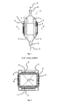
- Fig. 1 represents a side view of an example of acoustic cell according to the invention.
- Fig. 2 represents a top view of a cross section along the A-A' plane of the acoustic cell of fig.1
- Fig. 3 represents a schematic view of the regulating system of the invention.
- the present invention is related to a method for controlling the acoustic power and frequency injected in an acoustic cell.
- the acoustic cell comprises two opposed plates 5 defining a resonant cavity.
- An acoustic field is applied to the cavity by means of at least one piezoelectric 4 transducer fixed on the external surface of at least one of the opposed plates 5.
- the plate without transducer act as a mirror.
- a piezoelectric transducer is fixed on both plates. This allows the use of larger cells for a given injected power by each piezoelectric transducer, thereby reducing local heat dissipation.
- the plates have Knopp hardness HK 0.1/20 higher than 300, preferably higher than 480, and a density higher than the liquid density.
- This can be for example silicate glass, preferably borosilicate glass.
- the lateral sides of the acoustic cells comprises transparent viewing windows 3, for visual inspection of the filtering process (i.e. particles/cells agregation).
- An acoustic absorbing medium 10 is advantageously coated on those viewing window, in order to avoid complex reflexions on the windows, perturbing the resonant acoustic field. Silicone rubber is particularly adapted as absorbing medium.
- the inner dimensions of the cell, and the thickness of the plate are selected so that they are multiples of half of the wavelength of the injected sound.
- the properties of the liquid medium are varying around average values for example due to local temperature increase, particles density and composition of the liquid.
- acoustic cells preferably disposable.
- the dimensional tolerances are usually much broader than the tolerance obtained on expensive non disposable cells.
- the system can be calibrated once, reusing initially measured resonance frequency in subsequent uses. This is not realistically feasible in the case of disposable acoustic cells.
- the method of the invention does not only adapt the frequency to the resonance conditions, but also minimise the power injected in the liquid medium.
- phase shift phi between the applied electrical potential and the resulting electrical current is minimum.
- a convenient measurement of said phase shift phi is the measurement of the cosine of phi (cos(phi)), cos(phi) being maximum at resonance.
- the method of the invention is preferably controlled by a numerical processor controlling the frequency of a wave generator and the gain of an amplifier (power control) downstream of the wave generator, the piezoelectric transducer being connected to the output of the amplifier, as represented in Fig. 3 .
- an initial frequency is used to generate an acoustic field in the acoustic cell, and the gain of the amplifier is slowly increased until cos(phi) reaches a predetermined value.
- This step permits to obtain a sufficient signal to begin the tracking of the resonance frequency even in the case of badly known dimensions of the acoustic cell (disposable acoustic cell).
- the frequency is iteratively varied to increase cos(phi) and the power is decreased, so that in stable conditions, the resonance is maintained at the minimum feasible power input.
- the variation of the power and frequency is performed according to the following sequential steps:
- the determination of the direction of the gradient of cos(phi) can for example be determined by performing the minimum possible decrement of frequency, then measuring cos(phi), if cos(phi) has increased, this means that the gradient is negative and the frequency is decreased before getting back to step b, else, performing a double increment of the frequency, if cos(phi) has increased, it means that the gradient is positive, and the frequency is increased before getting back to step b. If cos(phi) has not increased in both directions (increment or decrement) the gradient is considered as being zero, and the frequency is maintained at its previous value before getting to step b.
- Sequences without acoustic field are used at periodical time in order to collect the particles agglutinated at the wave antinodes, the particles sedimenting when the acoustic field is stopped. Those stopping sequences are also used to perform a subsequent optimisation of the control parameters.
- the initial frequency applied to the transducers is determined by a dichotomic numerical method.
- a lag time of at least 1 ms, preferably 10ms, more preferably 100ms is used to let the system equilibrate after any frequency or power changes, before cos(phi) measurements.
- the method of the invention has been tested on disposable acoustic cells of the type represented in fig. 1 and 2 .
- the plates defining the resonant cavity where separated by 34mm.
- the plates themselves where made of glass plates of 1,2mm thickness.
- the plates dimensions where 41mm height and 31mm width.
- the wave generator was operated between 2,18 and 2.3MHz, the power control of the gain of the amplifier was performed by a step by step potentiometer, the power varying from 0 to 15W.
- the predetermined threshold of step b was 0,3538 and was identical to the predetermined value used in the initial step (see initial step hereabove).
- Typical operating cycle time is about 45s, separated by 5s lag time between each operating cycles.
- the system has shown robust behaviour in finding resonance conditions in disposable acoustic cells and in changing conditions, giving rise to better filtering conditions.
Abstract
The present invention is related to an iterative method for controlling an acoustic cell (1) separating dispersed particles in a liquid medium, said acoustic cell (1) comprising two opposed plates (5) delimiting a resonating cavity filled with said liquid medium, at least one of the opposed surfaces (4) comprising a piezoelectric transducer (4) coupled to an electrical power generator for producing ultrasonic waves in said resonating cavity, said method comprising the steps of:
a. applying an ultrasonic sound field by applying a periodic electrical potential of initial resonant frequency fi and initial power Pi to said piezoelectric transducer (5);
b. measuring the cosine of the resulting phase shift phi (cos(phi)) between the electric current and the electric potential applied to the transducer (5);
c. if the cos(phi) is lower than a predetermined threshold, increasing the power Pi, else decreasing the power Pi;
d. determining the sign of the gradient of cos(phi) as a function of the frequency;
e. varying the frequency in the gradient direction thereby maximising cos(phi);
f. getting to step (b).
Description
- The present invention is related to a method for regulating the power and frequency of an acoustic field applied to an acoustic cell. More particularly, the present invention is related to the regulation of the control parameters used in an acoustic cell for separating particles such as biological cells in a liquid medium.
- The present invention is also related to an acoustic cell to be controlled by the method of the invention.
- In biotechnologies, separating particles from a liquid medium has been the subject of research for a long time. At first, classical mechanical filters were used, but such kind of methods suffers several drawbacks. For example, the pressure and flow is limited by mechanical stress applied to the cells, or cell adhesion may occur on the filtering medium.
- A second strategy is based upon centrifugation. In that case, the developed systems are mechanically complex, and it is difficult to produce disposable parts that can provide continuous separation by centrifugation.
- Therefore, acoustic separation was developed, to solve some of those problems. In such separation methods, an acoustic field is applied to a resonant cavity, with the acoustic wave nodes and antinodes planes parallel to the direction of the liquid flow to be filtered. When a fluid comprising particles heavier than the surrounding medium pass through such acoustic field, the particles are trapped in the antinodes planes and accumulate in those planes. The particles can then be collected by periodically stopping the acoustic field and reversing the flow or let the particles sediment by gravity to a collecting tank. This can be performed by a backflush procedure wherein the acoustic cell is emptied by injecting a gas from above, the particles being collected along with the liquid flushed from the cell. In such system, the separation cell consist in a resonating cavity, comprising to opposed parallel plane surfaces, at least one of them being coupled to a piezoelectric transducer for producing the acoustic field. Document
EP0633049 discloses such an acoustic cell, and the corresponding filtering method. - In order to obtain optimum filtering in such a system, it is of key importance to have resonating conditions. Document
EP0633049 describes how to calculate the theoretical resonance frequencies of typical cavities, but, such frequencies are usually not perfectly stable. For example, small dimensional variation of the plate distance, particle density, and fluid temperature are known to have an important impact on the sound speed and therefore on the resonance frequency. - Therefore, the frequency is usually adapted in a closed loop regulation, by maximising the power transfer to the fluid. In order to make such frequency adjustment, the power needs to be sufficient at any time, so that the signal arising from the coupling with the filtered fluid is sufficient. Therefore, in such frequency tracking method, the power is permanently maintained higher than what is really needed for maintaining resonance conditions.
- An aim of the invention is to provide a method for continuously regulating both frequency and power applied to the piezoelectric transducer(s) of an acoustic cell wherein the injected power is minimised, and the resonance conditions are optimised.
- More particularly, the method of the invention aims to provide a regulating method of both power and frequency applied to an acoustic cell adapted to continuously filter particles from a fluid having varying physical properties such as sound speed, compressibility and density.
- An aim of the invention is to provide a regulating method sufficiently robust to be used for controlling disposable acoustic cells having broad dimensional tolerances.
- The present invention is related to an iterative method for controlling an acoustic cell separating dispersed particles in a liquid medium, said acoustic cell comprising two opposed plates delimiting a resonating cavity filled with said liquid medium, at least one of the opposed surfaces comprising a piezoelectric transducer coupled to an electrical power generator for producing ultrasonic waves in said resonating cavity, said method comprising the steps of:
- a) applying an ultrasonic acoustic field by applying a periodic electrical potential of frequency fi and power Pi to said piezoelectric transducer ;
- b) measuring the cosine of the resulting phase shift phi (cos(phi)) between the electric current and the electric potential applied to the transducer;
- c) if the cos(phi) is lower than a predetermined threshold, increasing the power Pi, else decreasing the power Pi;
- d) determining the sign of the gradient of cos(phi) as a function of the frequency;
- e) varying (increasing or decreasing) the frequency in the gradient direction thereby maximising cos(phi);
- f) getting to step (b).
- Preferred embodiments of the present invention disclose at least one or a suitable combination of the following features:
- the method comprising an initialisation step wherein the power is gradually increased until cos(phi) decreases below a predetermined initial value;
- the method comprising an initial frequency tracking step, wherein initial resonant frequency is determined;
- the initial frequency tracking is performed by a dichotomic search method;
- a lag time is inserted after any variation of the power or frequency before the cos(phi) measurement to let the system equilibrate before said measurement;
- the lag time is larger than 1ms, preferably 10ms, more preferably about 100ms.
- The present invention is also related to a disposable acoustic cell for separating particles dispersed in a liquid medium, said acoustic cell comprising a polymeric housing and two opposed plates, said polymeric housing and said opposed plates defining an enclosure for receiving a liquid comprising particles to be separated from said liquid by an acoustic wave field, a piezoelectric transducer being fixed on at least one of said opposing plates for applying the acoustic wave field between said plates.
- Preferred embodiments of the disposable acoustic cell of the invention disclose at least one or a suitable combination of the following features
- the opposed plates have a Knopp hardness HK 0.1/20 of 300 or more, preferably 480 or more;
- the distance between the opposed plates has a tolerance of more than 0.05mm;
- the side walls joining the opposed plates comprises acoustic absorbing means for inhibiting acoustic reflexion on said side walls;
- the means for inhibiting acoustic reflexion on said side walls comprises an elastomeric polymer such as a silicone rubber coated on said side walls;
- the polymer housing have vicat softening temperature according to ISO 306 is higher than 121°C;
- a piezoelectric transducer is fixed on both opposed plates;
- the opposed plates have a density higher than 1,1, preferably 1.5, more preferably higher then 2.
-
Fig. 1 represents a side view of an example of acoustic cell according to the invention. -
Fig. 2 represents a top view of a cross section along the A-A' plane of the acoustic cell offig.1 -
Fig. 3 represents a schematic view of the regulating system of the invention. -
- 1: acoustic cell
- 2: polymeric housing
- 3: viewing window
- 4: piezoelectric transducer
- 5: opposed plates
- 6: liquid inlet
- 7: upper wall, (means for inhibiting convection flow)
- 8: liquid outlet
- 9: outflow
- 10: absorbing layer
- 11: inflow
- The present invention is related to a method for controlling the acoustic power and frequency injected in an acoustic cell. As represented in
fig. 1 and 2 , the acoustic cell comprises twoopposed plates 5 defining a resonant cavity. An acoustic field is applied to the cavity by means of at least one piezoelectric 4 transducer fixed on the external surface of at least one of theopposed plates 5. When only onepiezoelectric transducer 4 is used, the plate without transducer act as a mirror. Preferably, a piezoelectric transducer is fixed on both plates. This allows the use of larger cells for a given injected power by each piezoelectric transducer, thereby reducing local heat dissipation. - In order to obtain an optimal coupling between the piezoelectric transducer and the liquid to be filtered, it is preferred that the plates have Knopp hardness HK 0.1/20 higher than 300, preferably higher than 480, and a density higher than the liquid density. This can be for example silicate glass, preferably borosilicate glass.
- Preferably the lateral sides of the acoustic cells comprises
transparent viewing windows 3, for visual inspection of the filtering process (i.e. particles/cells agregation). An acoustic absorbingmedium 10 is advantageously coated on those viewing window, in order to avoid complex reflexions on the windows, perturbing the resonant acoustic field. Silicone rubber is particularly adapted as absorbing medium. - In order to minimise heat dissipation at the different interfaces (piezo/plate and plate/liquid interfaces), the inner dimensions of the cell, and the thickness of the plate are selected so that they are multiples of half of the wavelength of the injected sound. Unfortunately, the properties of the liquid medium are varying around average values for example due to local temperature increase, particles density and composition of the liquid.
- Furthermore, in biotechnologies (i.e. when filtering the cells from a cell culture) in order to avoid cross contamination between different batches, or different types of cell culture, it is desirable to use sterilized acoustic cells, preferably disposable. When disposable, the dimensional tolerances are usually much broader than the tolerance obtained on expensive non disposable cells. Additionally, when non disposable cells are used the system can be calibrated once, reusing initially measured resonance frequency in subsequent uses. This is not realistically feasible in the case of disposable acoustic cells.
- Therefore, it is difficult to define the resonance frequency upfront, and this is even more difficult in the case of disposable acoustic cells. In prior art regulation methods, an initial acoustic power is applied to the transducer at a frequency close to the theoretical resonance frequency, and then the frequency is varied until resonance is obtained. The frequency is then slowly adapted to the changing parameters (temperature, particles density ...). Unfortunately, in order to have a sufficient initial signal the injected power has to be increased at a level above the optimum power needed to sustain the resonance conditions. This has the drawback of increasing temperature, potentially degrading the cells to be filtered, and also increase the power consumption. The temperature variation and gradient also induces instabilities in the resonant acoustic field and induces convection flows degrading the filtration performance.
- The method of the invention does not only adapt the frequency to the resonance conditions, but also minimise the power injected in the liquid medium.
- The load being capacitive, the maximum transmitted power occurs when the phase shift phi between the applied electrical potential and the resulting electrical current is minimum. A convenient measurement of said phase shift phi is the measurement of the cosine of phi (cos(phi)), cos(phi) being maximum at resonance.
- In the present invention, both the power and the frequency being simultaneously regulated for maximising only one parameter, it is difficult to use standard analogic method such as PID regulation modules. Therefore, the method of the invention is preferably controlled by a numerical processor controlling the frequency of a wave generator and the gain of an amplifier (power control) downstream of the wave generator, the piezoelectric transducer being connected to the output of the amplifier, as represented in
Fig. 3 . - Preferably, in an initial step, an initial frequency is used to generate an acoustic field in the acoustic cell, and the gain of the amplifier is slowly increased until cos(phi) reaches a predetermined value. This step permits to obtain a sufficient signal to begin the tracking of the resonance frequency even in the case of badly known dimensions of the acoustic cell (disposable acoustic cell).
- Then, the frequency is iteratively varied to increase cos(phi) and the power is decreased, so that in stable conditions, the resonance is maintained at the minimum feasible power input.
- After the initial step, the variation of the power and frequency is performed according to the following sequential steps:
- a. measuring the cosine of the resulting phase shift phi (cos(phi)) between the electric current and the electric potential applied to the transducer (5);
- b. if the cos(phi) is lower than a predetermined threshold, increasing the power Pi, else decreasing the power Pi;
- c. determining the sign of the gradient of cos(phi) as a function of the frequency;
- d. varying the frequency in the gradient direction thereby maximising cos(phi);
- e. getting to step (b).
- The determination of the direction of the gradient of cos(phi) can for example be determined by performing the minimum possible decrement of frequency, then measuring cos(phi), if cos(phi) has increased, this means that the gradient is negative and the frequency is decreased before getting back to step b, else, performing a double increment of the frequency, if cos(phi) has increased, it means that the gradient is positive, and the frequency is increased before getting back to step b. If cos(phi) has not increased in both directions (increment or decrement) the gradient is considered as being zero, and the frequency is maintained at its previous value before getting to step b.
- Sequences without acoustic field are used at periodical time in order to collect the particles agglutinated at the wave antinodes, the particles sedimenting when the acoustic field is stopped. Those stopping sequences are also used to perform a subsequent optimisation of the control parameters.
- Advantageously, the initial frequency applied to the transducers is determined by a dichotomic numerical method. In such a method, a minimum and a maximum frequency (fmin and fmax) are initially determined. This can be for example an arbitrary frequency +/- the frequency variation leading to an increment/decrement of nx by λ/4, n being the resonance mode, and λ being the wavelength. Variation of the frequency by more than such value would lead to jump from one resonance mode to another resonance mode, and would induce instabilities in the frequency tracking. So, at first, the direction of the gradient of cos(phi) is determined at f=(fmin+fmax)/2 and
- if gradient(cos(phi)) at f is positive then, fmin is replaced by the previous value of (fmin+fmax)/2
- if gradient(cos(phi)) at f is negative then, fmax is replaced by the previous value of (fmin+fmax)/2
- Advantageously, a lag time of at least 1 ms, preferably 10ms, more preferably 100ms is used to let the system equilibrate after any frequency or power changes, before cos(phi) measurements.
- The method of the invention has been tested on disposable acoustic cells of the type represented in
fig. 1 and 2 . The plates defining the resonant cavity where separated by 34mm. The plates themselves where made of glass plates of 1,2mm thickness. The plates dimensions where 41mm height and 31mm width. - The wave generator was operated between 2,18 and 2.3MHz, the power control of the gain of the amplifier was performed by a step by step potentiometer, the power varying from 0 to 15W. The predetermined threshold of step b was 0,3538 and was identical to the predetermined value used in the initial step (see initial step hereabove).
- Typical operating cycle time is about 45s, separated by 5s lag time between each operating cycles.
- The system has shown robust behaviour in finding resonance conditions in disposable acoustic cells and in changing conditions, giving rise to better filtering conditions.
Claims (14)
- Iterative method for controlling an acoustic cell (1) separating dispersed particles in a liquid medium, said acoustic cell (1) comprising two opposed plates (5) delimiting a resonating cavity filled with said liquid medium, at least one of the opposed surfaces (4) comprising a piezoelectric transducer (4) coupled to an electrical power generator for producing ultrasonic waves in said resonating cavity, said method comprising the steps of:a. applying an ultrasonic sound field by applying a periodic electrical potential of initial resonant frequency fi and initial power Pi to said piezoelectric transducer (5);b. measuring the cosine of the resulting phase shift phi (cos(phi)) between the electric current and the electric potential applied to the transducer (5);c. if the cos(phi) is lower than a predetermined threshold, increasing the power Pi, else decreasing the power Pi;d. determining the sign of the gradient of cos(phi) as a function of the frequency;e. varying the frequency in the gradient direction thereby maximising cos(phi);f. getting to step (b).
- The iterative method according claim 1 comprising an initialisation step for determining the initial power wherein the power is gradually increased until cos(phi) decreases below a predetermined initial value.
- The iterative method according to any of the previous claims comprising an initial frequency tracking step, wherein the initial resonant frequency is determined.
- The iterative method according to claim 3 wherein the initial frequency tracking is performed by a dichotomic search method.
- The iterative method according to any of the previous claims wherein a lag time is inserted after any variation of the power or frequency before the cos(phi) measurement to let the system equilibrate before said measurement.
- The iterative method according to claim 4 wherein the lag time is larger than 10ms, preferably about 100ms.
- Disposable acoustic cell for separating dispersed particles in a liquid medium, said acoustic cell comprising a polymeric housing and two opposed plates, said polymeric housing and said opposed plates defining an enclosure for receiving a liquid comprising particles to be separated from said liquid by an acoustic wave field, a piezoelectric transducer being fixed on at least one of said opposing plates for applying the acoustic wave field between said plates.
- Disposable acoustic cell according to claim 7 wherein the opposed plates have a Knopp hardness HK 0.1/20 of 300 or more.
- Disposable acoustic cell according to claim 7 or 8 wherein the distance between the opposed plates has a tolerance of more than 0.05mm.
- Disposable acoustic cell according to any of claims 7 to 9 wherein the side walls joining the opposed plates comprises acoustic absorbing means for inhibiting acoustic reflexion on said side walls.
- Disposable acoustic cell according to claim 10 wherein the means for inhibiting acoustic reflexion on said side walls comprises an elastomeric polymer coated on said side walls.
- Disposable acoustic cell according to any of claims 7 to 11 wherein the polymer housing have vicat softening temperature according to ISO 306 under 1kg is higher than 121°C.
- Disposable acoustic cell according to any of claims 7 to 12 wherein a piezoelectric transducer is fixed on both opposed plates.
- Disposable acoustic cell according to any of claims 7 to 13 wherein the opposed plates have a density higher than 1,1.
Priority Applications (2)
| Application Number | Priority Date | Filing Date | Title |
|---|---|---|---|
| EP13164759.6A EP2796208A1 (en) | 2013-04-22 | 2013-04-22 | Method for controlling an acoustic cell |
| PCT/EP2014/057685 WO2014173745A2 (en) | 2013-04-22 | 2014-04-16 | Method for controlling an acoustic cell |
Applications Claiming Priority (1)
| Application Number | Priority Date | Filing Date | Title |
|---|---|---|---|
| EP13164759.6A EP2796208A1 (en) | 2013-04-22 | 2013-04-22 | Method for controlling an acoustic cell |
Publications (1)
| Publication Number | Publication Date |
|---|---|
| EP2796208A1 true EP2796208A1 (en) | 2014-10-29 |
Family
ID=48366114
Family Applications (1)
| Application Number | Title | Priority Date | Filing Date |
|---|---|---|---|
| EP13164759.6A Withdrawn EP2796208A1 (en) | 2013-04-22 | 2013-04-22 | Method for controlling an acoustic cell |
Country Status (2)
| Country | Link |
|---|---|
| EP (1) | EP2796208A1 (en) |
| WO (1) | WO2014173745A2 (en) |
Cited By (2)
| Publication number | Priority date | Publication date | Assignee | Title |
|---|---|---|---|---|
| RU174330U1 (en) * | 2017-04-27 | 2017-10-11 | Федеральное государственное бюджетное образовательное учреждение высшего образования "Сибирский государственный университет геосистем и технологий" (СГУГиТ) | Acoustic trap in a standing wave field based on two oncoming beams |
| CN109154516A (en) * | 2016-03-30 | 2019-01-04 | 江森自控科技公司 | liquid detecting system |
Families Citing this family (1)
| Publication number | Priority date | Publication date | Assignee | Title |
|---|---|---|---|---|
| WO2015003012A2 (en) | 2013-07-01 | 2015-01-08 | Olivier Berteau | Distributed perfusion bioreactor system for continuous culture of biological cells |
Citations (6)
| Publication number | Priority date | Publication date | Assignee | Title |
|---|---|---|---|---|
| US4689515A (en) * | 1985-09-30 | 1987-08-25 | Siemens Aktiengesellschaft | Method for operating an ultrasonic frequency generator |
| EP0633049A1 (en) | 1993-05-11 | 1995-01-11 | Trampler, Felix, Dipl. Ing. | Method for treating a liquid |
| US5711888A (en) * | 1993-05-11 | 1998-01-27 | Sonosep Biotech, Inc. | Multilayered piezoelectric resonator for the separation of suspended particles |
| US5892315A (en) * | 1996-06-26 | 1999-04-06 | Gipson; Lamar Heath | Apparatus and method for controlling an ultrasonic transducer |
| EP1195460A2 (en) * | 2000-09-28 | 2002-04-10 | Kao Corporation | Ultrasonic cleaning apparatus and ultrasonic cleaning method |
| US20110254519A1 (en) * | 2008-12-02 | 2011-10-20 | Hiroshi Hasegawa | Ultrasonic generator and program writing method |
-
2013
- 2013-04-22 EP EP13164759.6A patent/EP2796208A1/en not_active Withdrawn
-
2014
- 2014-04-16 WO PCT/EP2014/057685 patent/WO2014173745A2/en active Application Filing
Patent Citations (6)
| Publication number | Priority date | Publication date | Assignee | Title |
|---|---|---|---|---|
| US4689515A (en) * | 1985-09-30 | 1987-08-25 | Siemens Aktiengesellschaft | Method for operating an ultrasonic frequency generator |
| EP0633049A1 (en) | 1993-05-11 | 1995-01-11 | Trampler, Felix, Dipl. Ing. | Method for treating a liquid |
| US5711888A (en) * | 1993-05-11 | 1998-01-27 | Sonosep Biotech, Inc. | Multilayered piezoelectric resonator for the separation of suspended particles |
| US5892315A (en) * | 1996-06-26 | 1999-04-06 | Gipson; Lamar Heath | Apparatus and method for controlling an ultrasonic transducer |
| EP1195460A2 (en) * | 2000-09-28 | 2002-04-10 | Kao Corporation | Ultrasonic cleaning apparatus and ultrasonic cleaning method |
| US20110254519A1 (en) * | 2008-12-02 | 2011-10-20 | Hiroshi Hasegawa | Ultrasonic generator and program writing method |
Cited By (3)
| Publication number | Priority date | Publication date | Assignee | Title |
|---|---|---|---|---|
| CN109154516A (en) * | 2016-03-30 | 2019-01-04 | 江森自控科技公司 | liquid detecting system |
| US11162726B2 (en) | 2016-03-30 | 2021-11-02 | Johnson Controls Technology Company | Liquid detection system |
| RU174330U1 (en) * | 2017-04-27 | 2017-10-11 | Федеральное государственное бюджетное образовательное учреждение высшего образования "Сибирский государственный университет геосистем и технологий" (СГУГиТ) | Acoustic trap in a standing wave field based on two oncoming beams |
Also Published As
| Publication number | Publication date |
|---|---|
| WO2014173745A3 (en) | 2015-03-26 |
| WO2014173745A2 (en) | 2014-10-30 |
Similar Documents
| Publication | Publication Date | Title |
|---|---|---|
| KR102603273B1 (en) | Acoustic manipulation of particles at standing wavelengths | |
| Benes et al. | Ultrasonic separation of suspended particles | |
| EP2825279B1 (en) | Acoustophoretic multi-component separation technology platform | |
| EP2953700B1 (en) | Bioreactor using acoustic standing waves | |
| US9725690B2 (en) | Fluid dynamic sonic separator | |
| US20210268406A1 (en) | Electronic configuration and control for acoustic standing wave generation | |
| US9416344B2 (en) | Bioreactor using acoustic standing waves | |
| Glynne-Jones et al. | Mode-switching: A new technique for electronically varying the agglomeration position in an acoustic particle manipulator | |
| EP3747523A1 (en) | Acoustophoretic separation technology using multi-dimensional standing waves | |
| US11381922B2 (en) | Acoustic transducer driver and controller | |
| CN111225727B (en) | Automatic start and operation of acoustic transducer | |
| EP2796208A1 (en) | Method for controlling an acoustic cell | |
| Hawkes et al. | Acoustofluidics 22: Multi-wavelength resonators, applications and considerations | |
| US20200324225A1 (en) | Acoustic transducer controller configuration | |
| Chen et al. | Numerical simulation of the radiation force from transient acoustic fields: Application to laser-guided acoustic tweezers | |
| WO2023108473A1 (en) | Acoustic artificial structure-based particle sorting method | |
| AU2018261949B2 (en) | Acoustic transducer controller configuration | |
| Cappon et al. | Design basis of industrial acoustic separators | |
| Hawkes et al. | Multi-Wavelength Resonators, Applications and Considerations | |
| CN114535091A (en) | Particle sorting method based on sound artificial structure | |
| Hawkes Jeremy et al. | Positioning particles within liquids using ultrasound force fields |
Legal Events
| Date | Code | Title | Description |
|---|---|---|---|
| PUAI | Public reference made under article 153(3) epc to a published international application that has entered the european phase |
Free format text: ORIGINAL CODE: 0009012 |
|
| 17P | Request for examination filed |
Effective date: 20130422 |
|
| AK | Designated contracting states |
Kind code of ref document: A1 Designated state(s): AL AT BE BG CH CY CZ DE DK EE ES FI FR GB GR HR HU IE IS IT LI LT LU LV MC MK MT NL NO PL PT RO RS SE SI SK SM TR |
|
| AX | Request for extension of the european patent |
Extension state: BA ME |
|
| STAA | Information on the status of an ep patent application or granted ep patent |
Free format text: STATUS: THE APPLICATION IS DEEMED TO BE WITHDRAWN |
|
| 18D | Application deemed to be withdrawn |
Effective date: 20150430 |