EP2792334A1 - Orthopaedic implant - Google Patents
Orthopaedic implant Download PDFInfo
- Publication number
- EP2792334A1 EP2792334A1 EP14155805.6A EP14155805A EP2792334A1 EP 2792334 A1 EP2792334 A1 EP 2792334A1 EP 14155805 A EP14155805 A EP 14155805A EP 2792334 A1 EP2792334 A1 EP 2792334A1
- Authority
- EP
- European Patent Office
- Prior art keywords
- securement
- slot
- implant
- articulation
- fastener
- Prior art date
- Legal status (The legal status is an assumption and is not a legal conclusion. Google has not performed a legal analysis and makes no representation as to the accuracy of the status listed.)
- Granted
Links
- 239000007943 implant Substances 0.000 title claims abstract description 38
- 239000011148 porous material Substances 0.000 claims abstract description 9
- 210000000988 bone and bone Anatomy 0.000 claims description 24
- RTAQQCXQSZGOHL-UHFFFAOYSA-N Titanium Chemical compound [Ti] RTAQQCXQSZGOHL-UHFFFAOYSA-N 0.000 claims description 5
- 239000006260 foam Substances 0.000 claims description 5
- 239000010936 titanium Substances 0.000 claims description 5
- 229910052719 titanium Inorganic materials 0.000 claims description 5
- 230000008878 coupling Effects 0.000 claims description 2
- 238000010168 coupling process Methods 0.000 claims description 2
- 238000005859 coupling reaction Methods 0.000 claims description 2
- 238000000034 method Methods 0.000 description 17
- 210000004095 humeral head Anatomy 0.000 description 16
- 210000002758 humerus Anatomy 0.000 description 13
- 239000000463 material Substances 0.000 description 7
- 238000003780 insertion Methods 0.000 description 6
- 230000037431 insertion Effects 0.000 description 6
- 210000003484 anatomy Anatomy 0.000 description 5
- 230000002093 peripheral effect Effects 0.000 description 5
- 238000001356 surgical procedure Methods 0.000 description 5
- 239000012634 fragment Substances 0.000 description 4
- 229910052751 metal Inorganic materials 0.000 description 3
- 239000002184 metal Substances 0.000 description 3
- 238000000465 moulding Methods 0.000 description 3
- 210000002435 tendon Anatomy 0.000 description 2
- 241001653121 Glenoides Species 0.000 description 1
- WAIPAZQMEIHHTJ-UHFFFAOYSA-N [Cr].[Co] Chemical class [Cr].[Co] WAIPAZQMEIHHTJ-UHFFFAOYSA-N 0.000 description 1
- 238000013459 approach Methods 0.000 description 1
- 206010003246 arthritis Diseases 0.000 description 1
- 230000036770 blood supply Effects 0.000 description 1
- 230000005786 degenerative changes Effects 0.000 description 1
- 238000002594 fluoroscopy Methods 0.000 description 1
- -1 for example Substances 0.000 description 1
- 238000002513 implantation Methods 0.000 description 1
- 238000009434 installation Methods 0.000 description 1
- 210000001503 joint Anatomy 0.000 description 1
- 238000004519 manufacturing process Methods 0.000 description 1
- 230000001483 mobilizing effect Effects 0.000 description 1
- 210000003205 muscle Anatomy 0.000 description 1
- 230000017074 necrotic cell death Effects 0.000 description 1
- 210000005036 nerve Anatomy 0.000 description 1
- 210000000062 pectoralis major Anatomy 0.000 description 1
- 210000000513 rotator cuff Anatomy 0.000 description 1
- 210000000323 shoulder joint Anatomy 0.000 description 1
- 210000004872 soft tissue Anatomy 0.000 description 1
- 210000003462 vein Anatomy 0.000 description 1
Images


Classifications
-
- A—HUMAN NECESSITIES
- A61—MEDICAL OR VETERINARY SCIENCE; HYGIENE
- A61F—FILTERS IMPLANTABLE INTO BLOOD VESSELS; PROSTHESES; DEVICES PROVIDING PATENCY TO, OR PREVENTING COLLAPSING OF, TUBULAR STRUCTURES OF THE BODY, e.g. STENTS; ORTHOPAEDIC, NURSING OR CONTRACEPTIVE DEVICES; FOMENTATION; TREATMENT OR PROTECTION OF EYES OR EARS; BANDAGES, DRESSINGS OR ABSORBENT PADS; FIRST-AID KITS
- A61F2/00—Filters implantable into blood vessels; Prostheses, i.e. artificial substitutes or replacements for parts of the body; Appliances for connecting them with the body; Devices providing patency to, or preventing collapsing of, tubular structures of the body, e.g. stents
- A61F2/02—Prostheses implantable into the body
- A61F2/30—Joints
- A61F2/40—Joints for shoulders
- A61F2/4003—Replacing only the epiphyseal or metaphyseal parts of the humerus, i.e. endoprosthesis not comprising an entire humeral shaft
-
- A—HUMAN NECESSITIES
- A61—MEDICAL OR VETERINARY SCIENCE; HYGIENE
- A61F—FILTERS IMPLANTABLE INTO BLOOD VESSELS; PROSTHESES; DEVICES PROVIDING PATENCY TO, OR PREVENTING COLLAPSING OF, TUBULAR STRUCTURES OF THE BODY, e.g. STENTS; ORTHOPAEDIC, NURSING OR CONTRACEPTIVE DEVICES; FOMENTATION; TREATMENT OR PROTECTION OF EYES OR EARS; BANDAGES, DRESSINGS OR ABSORBENT PADS; FIRST-AID KITS
- A61F2/00—Filters implantable into blood vessels; Prostheses, i.e. artificial substitutes or replacements for parts of the body; Appliances for connecting them with the body; Devices providing patency to, or preventing collapsing of, tubular structures of the body, e.g. stents
- A61F2/02—Prostheses implantable into the body
- A61F2/30—Joints
- A61F2/40—Joints for shoulders
- A61F2/4014—Humeral heads or necks; Connections of endoprosthetic heads or necks to endoprosthetic humeral shafts
-
- A—HUMAN NECESSITIES
- A61—MEDICAL OR VETERINARY SCIENCE; HYGIENE
- A61B—DIAGNOSIS; SURGERY; IDENTIFICATION
- A61B17/00—Surgical instruments, devices or methods, e.g. tourniquets
- A61B17/56—Surgical instruments or methods for treatment of bones or joints; Devices specially adapted therefor
- A61B17/58—Surgical instruments or methods for treatment of bones or joints; Devices specially adapted therefor for osteosynthesis, e.g. bone plates, screws, setting implements or the like
- A61B17/68—Internal fixation devices, including fasteners and spinal fixators, even if a part thereof projects from the skin
- A61B17/74—Devices for the head or neck or trochanter of the femur
- A61B17/742—Devices for the head or neck or trochanter of the femur having one or more longitudinal elements oriented along or parallel to the axis of the neck
- A61B17/746—Devices for the head or neck or trochanter of the femur having one or more longitudinal elements oriented along or parallel to the axis of the neck the longitudinal elements coupled to a plate opposite the femoral head
-
- A—HUMAN NECESSITIES
- A61—MEDICAL OR VETERINARY SCIENCE; HYGIENE
- A61B—DIAGNOSIS; SURGERY; IDENTIFICATION
- A61B17/00—Surgical instruments, devices or methods, e.g. tourniquets
- A61B17/56—Surgical instruments or methods for treatment of bones or joints; Devices specially adapted therefor
- A61B17/58—Surgical instruments or methods for treatment of bones or joints; Devices specially adapted therefor for osteosynthesis, e.g. bone plates, screws, setting implements or the like
- A61B17/68—Internal fixation devices, including fasteners and spinal fixators, even if a part thereof projects from the skin
- A61B17/80—Cortical plates, i.e. bone plates; Instruments for holding or positioning cortical plates, or for compressing bones attached to cortical plates
- A61B17/8052—Cortical plates, i.e. bone plates; Instruments for holding or positioning cortical plates, or for compressing bones attached to cortical plates immobilised relative to screws by interlocking form of the heads and plate holes, e.g. conical or threaded
- A61B17/8057—Cortical plates, i.e. bone plates; Instruments for holding or positioning cortical plates, or for compressing bones attached to cortical plates immobilised relative to screws by interlocking form of the heads and plate holes, e.g. conical or threaded the interlocking form comprising a thread
-
- A—HUMAN NECESSITIES
- A61—MEDICAL OR VETERINARY SCIENCE; HYGIENE
- A61B—DIAGNOSIS; SURGERY; IDENTIFICATION
- A61B17/00—Surgical instruments, devices or methods, e.g. tourniquets
- A61B17/56—Surgical instruments or methods for treatment of bones or joints; Devices specially adapted therefor
- A61B17/58—Surgical instruments or methods for treatment of bones or joints; Devices specially adapted therefor for osteosynthesis, e.g. bone plates, screws, setting implements or the like
- A61B17/68—Internal fixation devices, including fasteners and spinal fixators, even if a part thereof projects from the skin
- A61B17/80—Cortical plates, i.e. bone plates; Instruments for holding or positioning cortical plates, or for compressing bones attached to cortical plates
- A61B17/8061—Cortical plates, i.e. bone plates; Instruments for holding or positioning cortical plates, or for compressing bones attached to cortical plates specially adapted for particular bones
-
- A—HUMAN NECESSITIES
- A61—MEDICAL OR VETERINARY SCIENCE; HYGIENE
- A61B—DIAGNOSIS; SURGERY; IDENTIFICATION
- A61B17/00—Surgical instruments, devices or methods, e.g. tourniquets
- A61B17/56—Surgical instruments or methods for treatment of bones or joints; Devices specially adapted therefor
- A61B17/58—Surgical instruments or methods for treatment of bones or joints; Devices specially adapted therefor for osteosynthesis, e.g. bone plates, screws, setting implements or the like
- A61B17/68—Internal fixation devices, including fasteners and spinal fixators, even if a part thereof projects from the skin
- A61B17/84—Fasteners therefor or fasteners being internal fixation devices
- A61B17/86—Pins or screws or threaded wires; nuts therefor
- A61B17/8605—Heads, i.e. proximal ends projecting from bone
-
- A—HUMAN NECESSITIES
- A61—MEDICAL OR VETERINARY SCIENCE; HYGIENE
- A61B—DIAGNOSIS; SURGERY; IDENTIFICATION
- A61B17/00—Surgical instruments, devices or methods, e.g. tourniquets
- A61B17/56—Surgical instruments or methods for treatment of bones or joints; Devices specially adapted therefor
- A61B17/58—Surgical instruments or methods for treatment of bones or joints; Devices specially adapted therefor for osteosynthesis, e.g. bone plates, screws, setting implements or the like
- A61B17/68—Internal fixation devices, including fasteners and spinal fixators, even if a part thereof projects from the skin
- A61B17/84—Fasteners therefor or fasteners being internal fixation devices
- A61B17/86—Pins or screws or threaded wires; nuts therefor
- A61B17/8625—Shanks, i.e. parts contacting bone tissue
-
- A—HUMAN NECESSITIES
- A61—MEDICAL OR VETERINARY SCIENCE; HYGIENE
- A61F—FILTERS IMPLANTABLE INTO BLOOD VESSELS; PROSTHESES; DEVICES PROVIDING PATENCY TO, OR PREVENTING COLLAPSING OF, TUBULAR STRUCTURES OF THE BODY, e.g. STENTS; ORTHOPAEDIC, NURSING OR CONTRACEPTIVE DEVICES; FOMENTATION; TREATMENT OR PROTECTION OF EYES OR EARS; BANDAGES, DRESSINGS OR ABSORBENT PADS; FIRST-AID KITS
- A61F2/00—Filters implantable into blood vessels; Prostheses, i.e. artificial substitutes or replacements for parts of the body; Appliances for connecting them with the body; Devices providing patency to, or preventing collapsing of, tubular structures of the body, e.g. stents
- A61F2/02—Prostheses implantable into the body
- A61F2/30—Joints
- A61F2/30721—Accessories
- A61F2/30749—Fixation appliances for connecting prostheses to the body
-
- A—HUMAN NECESSITIES
- A61—MEDICAL OR VETERINARY SCIENCE; HYGIENE
- A61B—DIAGNOSIS; SURGERY; IDENTIFICATION
- A61B17/00—Surgical instruments, devices or methods, e.g. tourniquets
- A61B17/56—Surgical instruments or methods for treatment of bones or joints; Devices specially adapted therefor
- A61B2017/564—Methods for bone or joint treatment
-
- A—HUMAN NECESSITIES
- A61—MEDICAL OR VETERINARY SCIENCE; HYGIENE
- A61F—FILTERS IMPLANTABLE INTO BLOOD VESSELS; PROSTHESES; DEVICES PROVIDING PATENCY TO, OR PREVENTING COLLAPSING OF, TUBULAR STRUCTURES OF THE BODY, e.g. STENTS; ORTHOPAEDIC, NURSING OR CONTRACEPTIVE DEVICES; FOMENTATION; TREATMENT OR PROTECTION OF EYES OR EARS; BANDAGES, DRESSINGS OR ABSORBENT PADS; FIRST-AID KITS
- A61F2/00—Filters implantable into blood vessels; Prostheses, i.e. artificial substitutes or replacements for parts of the body; Appliances for connecting them with the body; Devices providing patency to, or preventing collapsing of, tubular structures of the body, e.g. stents
- A61F2/02—Prostheses implantable into the body
- A61F2/30—Joints
- A61F2002/30001—Additional features of subject-matter classified in A61F2/28, A61F2/30 and subgroups thereof
- A61F2002/30003—Material related properties of the prosthesis or of a coating on the prosthesis
- A61F2002/3006—Properties of materials and coating materials
- A61F2002/30077—Properties of materials and coating materials shrinkable
-
- A—HUMAN NECESSITIES
- A61—MEDICAL OR VETERINARY SCIENCE; HYGIENE
- A61F—FILTERS IMPLANTABLE INTO BLOOD VESSELS; PROSTHESES; DEVICES PROVIDING PATENCY TO, OR PREVENTING COLLAPSING OF, TUBULAR STRUCTURES OF THE BODY, e.g. STENTS; ORTHOPAEDIC, NURSING OR CONTRACEPTIVE DEVICES; FOMENTATION; TREATMENT OR PROTECTION OF EYES OR EARS; BANDAGES, DRESSINGS OR ABSORBENT PADS; FIRST-AID KITS
- A61F2/00—Filters implantable into blood vessels; Prostheses, i.e. artificial substitutes or replacements for parts of the body; Appliances for connecting them with the body; Devices providing patency to, or preventing collapsing of, tubular structures of the body, e.g. stents
- A61F2/02—Prostheses implantable into the body
- A61F2/30—Joints
- A61F2002/30001—Additional features of subject-matter classified in A61F2/28, A61F2/30 and subgroups thereof
- A61F2002/30316—The prosthesis having different structural features at different locations within the same prosthesis; Connections between prosthetic parts; Special structural features of bone or joint prostheses not otherwise provided for
- A61F2002/30329—Connections or couplings between prosthetic parts, e.g. between modular parts; Connecting elements
- A61F2002/30331—Connections or couplings between prosthetic parts, e.g. between modular parts; Connecting elements made by longitudinally pushing a protrusion into a complementarily-shaped recess, e.g. held by friction fit
- A61F2002/30332—Conically- or frustoconically-shaped protrusion and recess
-
- A—HUMAN NECESSITIES
- A61—MEDICAL OR VETERINARY SCIENCE; HYGIENE
- A61F—FILTERS IMPLANTABLE INTO BLOOD VESSELS; PROSTHESES; DEVICES PROVIDING PATENCY TO, OR PREVENTING COLLAPSING OF, TUBULAR STRUCTURES OF THE BODY, e.g. STENTS; ORTHOPAEDIC, NURSING OR CONTRACEPTIVE DEVICES; FOMENTATION; TREATMENT OR PROTECTION OF EYES OR EARS; BANDAGES, DRESSINGS OR ABSORBENT PADS; FIRST-AID KITS
- A61F2/00—Filters implantable into blood vessels; Prostheses, i.e. artificial substitutes or replacements for parts of the body; Appliances for connecting them with the body; Devices providing patency to, or preventing collapsing of, tubular structures of the body, e.g. stents
- A61F2/02—Prostheses implantable into the body
- A61F2/30—Joints
- A61F2002/30001—Additional features of subject-matter classified in A61F2/28, A61F2/30 and subgroups thereof
- A61F2002/30316—The prosthesis having different structural features at different locations within the same prosthesis; Connections between prosthetic parts; Special structural features of bone or joint prostheses not otherwise provided for
- A61F2002/30329—Connections or couplings between prosthetic parts, e.g. between modular parts; Connecting elements
- A61F2002/30433—Connections or couplings between prosthetic parts, e.g. between modular parts; Connecting elements using additional screws, bolts, dowels, rivets or washers e.g. connecting screws
-
- A—HUMAN NECESSITIES
- A61—MEDICAL OR VETERINARY SCIENCE; HYGIENE
- A61F—FILTERS IMPLANTABLE INTO BLOOD VESSELS; PROSTHESES; DEVICES PROVIDING PATENCY TO, OR PREVENTING COLLAPSING OF, TUBULAR STRUCTURES OF THE BODY, e.g. STENTS; ORTHOPAEDIC, NURSING OR CONTRACEPTIVE DEVICES; FOMENTATION; TREATMENT OR PROTECTION OF EYES OR EARS; BANDAGES, DRESSINGS OR ABSORBENT PADS; FIRST-AID KITS
- A61F2/00—Filters implantable into blood vessels; Prostheses, i.e. artificial substitutes or replacements for parts of the body; Appliances for connecting them with the body; Devices providing patency to, or preventing collapsing of, tubular structures of the body, e.g. stents
- A61F2/02—Prostheses implantable into the body
- A61F2/30—Joints
- A61F2/30767—Special external or bone-contacting surface, e.g. coating for improving bone ingrowth
- A61F2/30771—Special external or bone-contacting surface, e.g. coating for improving bone ingrowth applied in original prostheses, e.g. holes or grooves
- A61F2002/30772—Apertures or holes, e.g. of circular cross section
- A61F2002/30777—Oblong apertures
-
- A—HUMAN NECESSITIES
- A61—MEDICAL OR VETERINARY SCIENCE; HYGIENE
- A61F—FILTERS IMPLANTABLE INTO BLOOD VESSELS; PROSTHESES; DEVICES PROVIDING PATENCY TO, OR PREVENTING COLLAPSING OF, TUBULAR STRUCTURES OF THE BODY, e.g. STENTS; ORTHOPAEDIC, NURSING OR CONTRACEPTIVE DEVICES; FOMENTATION; TREATMENT OR PROTECTION OF EYES OR EARS; BANDAGES, DRESSINGS OR ABSORBENT PADS; FIRST-AID KITS
- A61F2/00—Filters implantable into blood vessels; Prostheses, i.e. artificial substitutes or replacements for parts of the body; Appliances for connecting them with the body; Devices providing patency to, or preventing collapsing of, tubular structures of the body, e.g. stents
- A61F2/02—Prostheses implantable into the body
- A61F2/30—Joints
- A61F2/30767—Special external or bone-contacting surface, e.g. coating for improving bone ingrowth
- A61F2/30771—Special external or bone-contacting surface, e.g. coating for improving bone ingrowth applied in original prostheses, e.g. holes or grooves
- A61F2002/30772—Apertures or holes, e.g. of circular cross section
- A61F2002/30784—Plurality of holes
- A61F2002/30787—Plurality of holes inclined obliquely with respect to each other
-
- A—HUMAN NECESSITIES
- A61—MEDICAL OR VETERINARY SCIENCE; HYGIENE
- A61F—FILTERS IMPLANTABLE INTO BLOOD VESSELS; PROSTHESES; DEVICES PROVIDING PATENCY TO, OR PREVENTING COLLAPSING OF, TUBULAR STRUCTURES OF THE BODY, e.g. STENTS; ORTHOPAEDIC, NURSING OR CONTRACEPTIVE DEVICES; FOMENTATION; TREATMENT OR PROTECTION OF EYES OR EARS; BANDAGES, DRESSINGS OR ABSORBENT PADS; FIRST-AID KITS
- A61F2/00—Filters implantable into blood vessels; Prostheses, i.e. artificial substitutes or replacements for parts of the body; Appliances for connecting them with the body; Devices providing patency to, or preventing collapsing of, tubular structures of the body, e.g. stents
- A61F2/02—Prostheses implantable into the body
- A61F2/30—Joints
- A61F2/30767—Special external or bone-contacting surface, e.g. coating for improving bone ingrowth
- A61F2002/3092—Special external or bone-contacting surface, e.g. coating for improving bone ingrowth having an open-celled or open-pored structure
-
- A—HUMAN NECESSITIES
- A61—MEDICAL OR VETERINARY SCIENCE; HYGIENE
- A61F—FILTERS IMPLANTABLE INTO BLOOD VESSELS; PROSTHESES; DEVICES PROVIDING PATENCY TO, OR PREVENTING COLLAPSING OF, TUBULAR STRUCTURES OF THE BODY, e.g. STENTS; ORTHOPAEDIC, NURSING OR CONTRACEPTIVE DEVICES; FOMENTATION; TREATMENT OR PROTECTION OF EYES OR EARS; BANDAGES, DRESSINGS OR ABSORBENT PADS; FIRST-AID KITS
- A61F2/00—Filters implantable into blood vessels; Prostheses, i.e. artificial substitutes or replacements for parts of the body; Appliances for connecting them with the body; Devices providing patency to, or preventing collapsing of, tubular structures of the body, e.g. stents
- A61F2/02—Prostheses implantable into the body
- A61F2/30—Joints
- A61F2/40—Joints for shoulders
- A61F2/4003—Replacing only the epiphyseal or metaphyseal parts of the humerus, i.e. endoprosthesis not comprising an entire humeral shaft
- A61F2002/4007—Replacing only the epiphyseal or metaphyseal parts of the humerus, i.e. endoprosthesis not comprising an entire humeral shaft implanted without ablation of the whole natural humeral head
Definitions
- the present invention relates generally to orthopaedic implants, and more particularly, to orthopaedic implants for repairing and/or replacing natural joints.
- a natural joint may undergo degenerative changes for a variety or reasons, for instance arthritis.
- a joint may be sufficiently fractured or otherwise damaged by an external force.
- it may be necessary to replace a natural joint or portions of a natural joint with a prosthetic joint or portions of a prosthetic joint.
- the shoulder joint One such natural joint that may need replacement is the shoulder joint.
- Conventional shoulder prostheses comprise a humeral implant and optionally a glenoid implant.
- the humeral implant comprises a stem for insertion into a bore extending into the intramedullary canal generally along the longitudinal axis of the bone and an articulation component, such as a convex bearing head.
- the articulation component is coupled to a neck portion of the stem, which extends from the intramedullary canal at an inclined angle relative to the longitudinal axis of a distal portion of the stem in order to recreate the arrangement of the natural joint.
- the invention provides an orthopaedic implant which comprises a fixation plate and an articulation component comprising a bearing surface and an opposing securement surface formed of a porous material.
- the implant further includes at least one fastener extending through the fixation plate and secured within the porous material of the securement surface of the articulation component.
- the articulation component may include an articulation head having a convex outer surface forming the articulation surface and a reverse surface opposite the convex outer surface.
- a securement disk having an attachment surface may be disposed adjacent the reverse surface of the articulation head.
- the securement disk may include a securement surface and at least one radial slot formed in the securement surface and adapted to accept the at least one fastener.
- a shorter fastener may be secured within the radial slot near an inner edge of the radial slot and a longer fastener may be secured within the radial slot near an outer edge of the radial slot, thereby allowing flexibility in the length of fasteners used with the articulation component.
- the radial slot may extend into the securement disk between the securement surface and the attachment surface.
- the radial slot may include at least one wall along extending outwardly from at least a portion of a perimeter of the slot, in which the fastener may engage the at least one wall and a wall forming the slot to retain the fastener within the slot.
- the implant may include a plurality of fasteners and a plurality of radial slots within the securement disk, in which each of the plurality of fasteners is secured within a respective radial slot of the plurality of radial slots.
- the securement disk may be formed of titanium foam.
- the invention also provides an orthopaedic implant which includes an articulation head comprising a bearing surface and a reverse surface and a securement disk.
- the securement disk has an attachment surface attached to at least a portion of the reverse surface of the articulation head and a securement surface opposite the attachment surface and adapted for coupling to a fixation plate secured to a bone. At least one opening is formed in the securement surface which can accept fasteners therein.
- the securement disk is formed from a porous material.
- the at least one opening may be in the form of a radial slot formed in the securement surface and adapted to accept fasteners.
- a shorter fastener may be secured within the radial slot near an inner edge of the slot and a longer fastener may be secured within the radial slot near an outer edge of the slot, thereby allowing flexibility in the length of fasteners used with the articulation component.
- the radial slot may extend into the securement disk between the securement surface and the attachment surface.
- the radial slot may include at least one wall along extending outwardly from at least a portion of a perimeter of the slot, in which the fastener may engage the at least one wall and a wall forming the slot to retain the fasteners within the slot.
- the securement disk may be formed of titanium foam.
- Implants provided by the invention can be implanted using a method which includes the step of selecting at least a fixation plate and a set of fasteners for a patient, in which the fixation plate and the set of fasteners correspond to the natural anatomy of a patient.
- the method further includes the steps of accessing the fractured bone and assessing the extent of fracture of the bone. If the extent of the fracture is at a first level, the fixation plate, an articulation component selected based on the patient's natural anatomy, and the set of fasteners are utilized to replace a portion of the fractured bone. If the extent of the fracture is at a second level different than the first level, only the fixation plate and the set of fasteners are utilized to repair the fractured bone.
- the method may further include the steps of removing a head of the fractured bone and securing the fixation plate to a surface of the fractured bone.
- the method may further include the steps of positioning the articulation component in the place of the head, aligning the articulation component with the fixation plate, and inserting the fasteners through the fixation plate and the articulation component to secure the articulation component to the fixation plate.
- the method may further include the steps of selecting a set of fasteners having a length and securing the set of fasteners in radial slots formed in the articulation component.
- the structure of the articulation component forming the radial slots may be formed of a porous material.
- the length of the set of fasteners and a placement of the fasteners within the radial slots may determine a neck length.
- the aligning step may include the steps of inserting a first end of an instrument through a hole in the fixation plate and guiding the first end into a hole formed within the articulation component. These steps set a neck length between the fixation plate and the articulation component and prevent rotation of the articulation component during placement of the fasteners.
- the method may further include the steps of securing the fixation plate to the bone and inserting the fasteners through the fixation plate and into a fractured native articulation component to secure the fractured native articulation component to the fixation plate.
- Terms representing anatomical references such as anterior, posterior, medial, lateral, superior and inferior may be used throughout document to refer to both the orthopaedic implants and instruments described herein and a patient's natural anatomy. Such terms have well-understood meanings in both the study of anatomy and the field of orthopaedics. Use of such anatomical reference terms in this document is intended to be consistent with their well-understood meanings unless noted otherwise.
- FIGS. 1 and 2 show an orthopaedic implant 20 which includes a fixation plate 22, a plurality of fasteners 24, for example screws, and an articulation component 26.
- the fixation plate 22 comprises an elongate body 30 and a head 32 arranged to conform to the surface of the lateral surface 33 of the proximal humerus 34.
- a plurality of screw holes 36 are formed within the body 30 for securing the fixation plate 22 to the proximal humerus 34 with bone screws 38, as shown in FIG. 9 . Any suitable number of screw holes 36 and corresponding bone screws 38 may be utilized to attach the fixation plate 22 to the proximal humerus 34.
- a slotted screw hole 44 is also provided for initial fixation of the fixation plate 22 to the proximal humerus 34.
- a bone screw 38 may be inserted into the proximal humerus 34 through the slotted hole 44, allowing the fixation plate 22 to slide along the proximal humerus 34 before the fixation plate 22 is permanently attached.
- the head 32 of the fixation plate 22 extends from the body 30 and the head 32 tapers outwardly as it moves away from the body 30 to conform to the shape of the proximal humerus 34.
- the head 32 of the fixation plate 22 includes a number of screw holes 50 and a guide hole 52. As described below, the screws 24 and/or an instrument 142 may be inserted through the screw holes 50 and the guide hole 52 to secure the fixation plate 22 to the articulation component 26 or a humeral head 120.
- the guide hole 52 is disposed below the screw holes 50 and may be utilized in combination with an instrument 142 to align the fixation plate 22 with the articulation component 26.
- the screws 24 may be configured to be inserted into bone, titanium foam, and/or any other suitable material.
- the screws 24 include threading that is sized to mate with threading formed within the screw holes 50. Heads 60 of the screws have a diameter that is larger than the threading of the screws 24 and the screw holes 50. In this manner, the screw heads 60 abut annular ledges 62, as seen in FIG. 4 , formed within the screw holes 50 when inserted into the screw holes.
- the articulation component 26 includes a securement disk 70, a connector 72, and an articulation head 74.
- the articulation head 74 includes a convex bearing surface 76 that may be defined by a portion of a sphere.
- the articulation head 74 further includes a reverse surface 78 defining a recess 80 for positioning of the securement disk 70 therein.
- the reverse surface 78 may include a partially spherical surface 82 and a planar surface 84, in which a bore 86 is formed within the planar surface 84.
- the bore 86 is formed by a tapered wall 88 extending from the planar surface 84 toward the convex bearing surface 76, in which the bore 86 terminates before reaching the convex bearing surface 76.
- the articulation head 74 may be constructed with biocompatible metal, such as a cobalt chromium alloy, although other materials may also be used.
- the securement disk 70 of the articulation component 26 includes an attachment surface 90 and a securement surface 92 that are generally parallel.
- a partially spherical side surface 94 extends between the attachment and securement surfaces 90, 92 and may have a shape that generally conforms to a shape of the partially spherical surface 82 of the articulation head 74.
- the securement disk 70 may further include a central circular hole 96, four radial slots 98 spaced from the central hole 96 and extending toward the side surface 94, and four circular holes 100 having a smaller diameter than the central hole 96 and being spaced between each pair of radial slots 98.
- the securement disk 70 may be constructed of a porous metal, for example, titanium foam or any other suitable material.
- the radial slots 98 may optionally include peripheral walls 101 extending outwardly from the securement surface 92 and surrounding the respective slots 98.
- walls forming the radial slots 98 are smooth. It is also envisaged that the walls forming the radial slots 98 and/or the peripheral walls 101 may include threads to facilitate insertion of the screws 24 into the radial slots 98, as will be discussed in greater detail below.
- the slots 98 may alternatively extend through only a portion of the securement disk 70. Specifically, the slots 98 need only be deep enough to provide a guide for insertion of the screws 24 into the securement disk 70.
- the connector 72 is depicted as having a distal end 102 that is generally cylindrical in shape and a proximal end 104 opposite the distal end 102 and which tapers inwardly as it extends away from the distal end 102.
- the connector 72 may be made of rubber, a polymeric material, a metal, or any other material suitable for forming a friction fit with the articulation head 74 and the securement disk 70.
- the securement disk 70 is secured to the articulation head 74 by the connector 72. More specifically, the securement disk 70 is moulded using known moulding methods.
- the distal end 102 of the connector 72 is inserted into the central circular hole 96 of the securement disk 70.
- the securement disk 70 shrinks around the distal end 102 of the connector 72 to form a friction fit to the distal end of the connector.
- the proximal end 104 of the connector 72 is then inserted into the bore 86 of the articulation head 74 and a mallet or other tool is used to force the proximal end 104 of the connector 72 into the bore 86 (e.g., by exerting pressure against the securement disk 70) to form a friction fit between the connector 72 and the tapered wall 88 forming the bore 86.
- These steps may be performed in any other suitable order. Different approaches to securing the securement disk 70 to the articulation head 74 may alternatively or additionally be used.
- a surgical procedure for implanting the orthopaedic implant 20 of FIGS. 1 and 2 to repair a fractured humeral head 120 will now be described. Details of the surgical procedure may be varied, for instance, according to the preferences of the surgeon.
- the proximal humerus 34 When the proximal humerus 34 is fractured, it generally breaks into several pieces, typically three or four.
- the humeral head 120 splits off at the level of the anatomical neck indicated by line 122, the greater tuberosity 124 and lesser tuberosity 126 are separated from the humeral shaft 128 below the tuberosities 124, 126, and the tuberosities 124, 126 are separated from one another along the biceptal groove 130. More specifically, the greater tuberosity 124 is displaced superiorly and posteriorly by the attached rotator cuff, while the lesser tuberosity 126 is retracted medially by the attached subscapularis.
- the fractured end of the humeral shaft 128 is displaced medially by the pull of the pectoralis major.
- the greater or lesser tuberosity 124, 126 remains attached to the humeral head 120, which in consequence is rotated internally by the subscapularis tendon. Necrosis may begin for both three part and four part fractures, as there is no longer a blood supply to the humeral head 120. If this is the case, the humeral head 120 may be replaced and the greater and lesser tuberosities 124, 126 are reattached to the humeral shaft 128.
- the surgeon must first gain access to the fractured humeral head 120.
- the patient is therefore positioned so as to allow the surgeon free access to the injured shoulder, for example, with the injured arm hanging free, thereby providing space for later manipulation of the arm.
- the fracture may be examined using fluoroscopy, including under internal and/or external rotation.
- a deltopectoral exposure may be used to identify the coracoid, acromium, and deltoid insertion.
- the interval between the pectoralis and the deltoid is developed and the incision line is extended distally from the coracoid.
- the exposure may be through a 12 to 14 cm incision.
- the incision may be held open using self retaining retractors. Care must be taken to identify and retract the cephalic vein.
- coraco-brachialis is retracted medially and the pectoralis insertion at the floor of the deltopectoral interval is located allowing the subacromial space to be developed to mobilize the proximal deltoid.
- Other methods of accessing the fracture humeral head 120 may be used.
- the fixation plate 22 may be provided in multiple sizes, so an appropriately sized fixation plate 22 is selected. An anterior side 140 of the fixation plate 22 is then aligned with the lateral surface 33 of the humeral shaft 128 and the fixation plate 22 is secured to the lateral surface 33 of the proximal humerus 34. More specifically, a bone screw 38 is inserted through the slotted screw hole 44 in the fixation plate 22 and secured to the humeral shaft 128 using known techniques. The slotted screw hole 44 allows the fixation plate 22 to be moved along the humeral shaft 128 to position the fixation plate 22 appropriately. Once positioned, the bone screw 38 within the slotted screw hole 44 is tightened within the lateral surface 33.
- Additional bone screws 38 may be inserted through the screw holes 36 of the fixation plate 22 and secured to the humeral shaft 128 using known techniques. The additional bone screws 38 may be secured to the humeral shaft 128 before or after connecting the fixation plate 22 to the articulation component 36, as described below.
- the surgeon may assess whether the fracture is at a level in which repair may be possible or at a level that necessitates replacement of the fractured humeral head 120. If the surgeon believes repair is possible, he may proceed as such. For example, in a fracture in which the humeral head 120 has not split off at the level of the anatomical neck indicated by the line 122, the humeral head 120 may not need to be replaced.
- the surgeon would install the screws 24 through any number of the five screw holes 50 and the guide hole 52. During this process, the surgeon would attempt to pull the fractured bone fragments back together and anchor ends of at least some of the screws 24 in the humeral head 120, as seen in FIG. 10 .
- the fixation plate 22 and the screws 24 provide a base system for both a repair and a replacement procedure and need not be removed when switching between a repair and a replacement procedure.
- the orthopaedic implant 20 provides a system that allows a surgeon to begin a surgical procedure with a particular plan in mind and switch the plan intra-operatively without the need to remove the fixation plate 22 and the fasteners 24 and/or implant others. Rather, the components of the orthopaedic implant 20 may be used in different manners for a repair (e.g., using only the fixation plate 22 and the screws 24) and a replacement (e.g., using the fixation plate 22, the screws 24, and the articulation component 26).
- a repair e.g., using only the fixation plate 22 and the screws 24
- a replacement e.g., using the fixation plate 22, the screws 24, and the articulation component 26.
- the detached humeral head 120 may be removed (after releasing the fractured head 120 from the greater or lesser tuberosity 124, 126 in the case of a three-part fracture).
- the articulation component 26 may be provided in a range of sizes that match the patient's natural humeral head. The appropriate size of articulation component 26 and screws 24 are selected to replicate the patient's natural humeral head and neck.
- the tuberosities 124, 126 are released from underlying soft tissues, taking care to protect the axillary nerve when mobilizing the lesser tuberosity and the attached subscapularis muscle tendon. The tuberosities 124, 126 are released to allow them to be coupled to each other and to the fixation plate 22.
- An instrument 142 may be used to align the fixation plate 22 with the articulation component 26.
- the instrument 142 may be used to set a neck length, or a distance between the fixation plate 22 and the articulation component 26, to match that of the natural anatomy of the patient.
- the instrument 142 includes a treaded central shaft 144, an elongate projection 146 extending from a first end 148 of the central shaft 144 and having a diameter smaller than a diameter of the central shaft 144, and an enlarged head 150 extending from a second end 152 of the central shaft 144 and having a diameter larger than the diameters of the central shaft 144 and the elongate projection 146.
- the elongate projection 146 is inserted through the guide hole 52 in the fixation plate 22. Simultaneously, or prior to insertion of the instrument 142, the articulation component 26 is positioned in the location of the removed humeral head 120. As the central shaft 144 reaches the guide hole 52, the threading on the central shaft 144 engages the threading of the guide hole 52, thereby requiring a user to rotate the instrument 142 to further insert the instrument 142 through the guide hole 52. The threading on the central shaft 144 and the guide hole 52 allow a surgeon to set the neck length. As the user rotates the instrument 142, the elongate projection 146 enters one of the four circular holes 100 disposed within the securement disk 70. Once the elongate projection 146 is disposed within one of the circular holes 100, the instrument 142 retains the fixation plate 22 and the articulation component 26 in alignment and prevents rotation of the articulation component 26.
- the screws 24 are inserted through the screw holes 50 in the fixation plate 22.
- the securement disk 70 of the articulation component 26 is aligned such that each of the screws 24 may be inserted into a respective radial slot 98 in the securement disk 70.
- a drill or other tool may be used to form bores in remaining bone fragments for receiving the screws 24.
- the screws 24 may extend above the fracture line of the humeral shaft 128, or minimal bone removal may be required. As each screw 24 reaches a respective radial slot 98, the threads of the screws 24 enter the radial slots 98.
- the threads of the screws 24 engage the radial slots 98 and/or the peripheral walls 101 and cut into the material of the securement disk 70. More specifically, the threads cut into the walls forming the radial slots 98 and/or the peripheral walls 101 to thereby secure the screws 24 to the securement disk 70. Since a thickness of the securement disk 70 is governed by the overall size of the articulation component 26, the peripheral walls 101 provide a greater height along which the screws 24 may engage the securement disk 70. Once the screws 24 are secured within the securement disk 70 of the articulation component 26, the instrument 142 may be removed.
- fixation plate 22 and the articulation component 26 may be alternatively or additionally aligned in any suitable manner and rotation of the articulation component 26 may be prevented in any suitable manner.
- the screws 24 are diverging and, thus, differently-sized screws 24 will contact the radial slots 98 at different points along the slots 98. For example, shorter screws 24 will contact the radial slots 98 closer to inner radial edges 160, as seen in FIGS. 5 and 6 , of the slots 98 and longer screws 24 will contact the radial slots 98 closer to outer radial edges 162 of the slots 98.
- the radial slots 98 therefore allow screws 24 of different lengths to be secured to the securement disk 70 without the need for a differently-sized securement disk 70 for every length of screws 24. The surgeon selects screws that are appropriate for the patient and which create the desired neck length for that patient.
- bone fragments such as the greater and lesser tuberosities 124, 126 may be attached in any suitable manner to the humeral shaft 128 to position and prevent movement of the bone fragments.
- Fasteners other than screws might be used for securing one or more components to relative to one other and/or to bone.
Abstract
Description
- The present invention relates generally to orthopaedic implants, and more particularly, to orthopaedic implants for repairing and/or replacing natural joints.
- A natural joint may undergo degenerative changes for a variety or reasons, for instance arthritis. Alternatively, a joint may be sufficiently fractured or otherwise damaged by an external force. When a joint is sufficiently degenerated or damaged, it may be necessary to replace a natural joint or portions of a natural joint with a prosthetic joint or portions of a prosthetic joint.
- One such natural joint that may need replacement is the shoulder joint. Conventional shoulder prostheses comprise a humeral implant and optionally a glenoid implant. Typically, the humeral implant comprises a stem for insertion into a bore extending into the intramedullary canal generally along the longitudinal axis of the bone and an articulation component, such as a convex bearing head. Typically, the articulation component is coupled to a neck portion of the stem, which extends from the intramedullary canal at an inclined angle relative to the longitudinal axis of a distal portion of the stem in order to recreate the arrangement of the natural joint.
- The invention provides an orthopaedic implant which comprises a fixation plate and an articulation component comprising a bearing surface and an opposing securement surface formed of a porous material. The implant further includes at least one fastener extending through the fixation plate and secured within the porous material of the securement surface of the articulation component.
- Optionally, the articulation component may include an articulation head having a convex outer surface forming the articulation surface and a reverse surface opposite the convex outer surface. A securement disk having an attachment surface may be disposed adjacent the reverse surface of the articulation head.
- Optionally, the securement disk may include a securement surface and at least one radial slot formed in the securement surface and adapted to accept the at least one fastener.
- Optionally, a shorter fastener may be secured within the radial slot near an inner edge of the radial slot and a longer fastener may be secured within the radial slot near an outer edge of the radial slot, thereby allowing flexibility in the length of fasteners used with the articulation component.
- Optionally, the radial slot may extend into the securement disk between the securement surface and the attachment surface.
- Optionally, the radial slot may include at least one wall along extending outwardly from at least a portion of a perimeter of the slot, in which the fastener may engage the at least one wall and a wall forming the slot to retain the fastener within the slot.
- Optionally, the implant may include a plurality of fasteners and a plurality of radial slots within the securement disk, in which each of the plurality of fasteners is secured within a respective radial slot of the plurality of radial slots.
- Optionally, the securement disk may be formed of titanium foam.
- The invention also provides an orthopaedic implant which includes an articulation head comprising a bearing surface and a reverse surface and a securement disk. The securement disk has an attachment surface attached to at least a portion of the reverse surface of the articulation head and a securement surface opposite the attachment surface and adapted for coupling to a fixation plate secured to a bone. At least one opening is formed in the securement surface which can accept fasteners therein. The securement disk is formed from a porous material.
- Optionally, the at least one opening may be in the form of a radial slot formed in the securement surface and adapted to accept fasteners.
- Optionally, a shorter fastener may be secured within the radial slot near an inner edge of the slot and a longer fastener may be secured within the radial slot near an outer edge of the slot, thereby allowing flexibility in the length of fasteners used with the articulation component.
- Optionally, the radial slot may extend into the securement disk between the securement surface and the attachment surface.
- Optionally, the radial slot may include at least one wall along extending outwardly from at least a portion of a perimeter of the slot, in which the fastener may engage the at least one wall and a wall forming the slot to retain the fasteners within the slot.
- Optionally, the securement disk may be formed of titanium foam.
- Implants provided by the invention can be implanted using a method which includes the step of selecting at least a fixation plate and a set of fasteners for a patient, in which the fixation plate and the set of fasteners correspond to the natural anatomy of a patient. The method further includes the steps of accessing the fractured bone and assessing the extent of fracture of the bone. If the extent of the fracture is at a first level, the fixation plate, an articulation component selected based on the patient's natural anatomy, and the set of fasteners are utilized to replace a portion of the fractured bone. If the extent of the fracture is at a second level different than the first level, only the fixation plate and the set of fasteners are utilized to repair the fractured bone.
- If the fracture is at the first level, the method may further include the steps of removing a head of the fractured bone and securing the fixation plate to a surface of the fractured bone. The method may further include the steps of positioning the articulation component in the place of the head, aligning the articulation component with the fixation plate, and inserting the fasteners through the fixation plate and the articulation component to secure the articulation component to the fixation plate.
- The method may further include the steps of selecting a set of fasteners having a length and securing the set of fasteners in radial slots formed in the articulation component. The structure of the articulation component forming the radial slots may be formed of a porous material. The length of the set of fasteners and a placement of the fasteners within the radial slots may determine a neck length.
- Optionally, the aligning step may include the steps of inserting a first end of an instrument through a hole in the fixation plate and guiding the first end into a hole formed within the articulation component. These steps set a neck length between the fixation plate and the articulation component and prevent rotation of the articulation component during placement of the fasteners.
- If the fracture is at the second level, the method may further include the steps of securing the fixation plate to the bone and inserting the fasteners through the fixation plate and into a fractured native articulation component to secure the fractured native articulation component to the fixation plate.
- The invention is described below by way of example with reference to the accompanying drawings, in which:
-
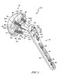
FIG. 1 is a top perspective view of an orthopaedic implant such as a humeral implant, including a fixation plate, an articulation component, and a plurality of fastenters for connecting the fixation plate and the articulation component. -
FIG. 2 is an exploded view of the implant ofFIG. 1 , showing the articulation component including a securement disk, an articulation head, and a connector for joining the securement disk and the articulation head. -
FIG. 3 is an enlarged, exploded view of the securement disk, the articulation head, and the connector of the articulation component ofFIG. 2 . -
FIG. 4 is a perspective view of the fixation plate ofFIG. 1 . -
FIGS. 5 and6 are bottom and top elevational views of the securement disk ofFIG. 2 , in which the securement disk includes a plurality of radial slots for accommodating the fasteners and a central circular hole for accommodating the connector ofFIGS. 2 and3 . -
FIG. 7 is a side elevational view of a four part fracture of a proximal humerus. -
FIG. 8A is a side elevational view of the orthopaedic implant ofFIG. 1 implanted within the proximal humerus ofFIG. 7 , showing a first end of an instrument extending through the fixation plate and a second end of the instrument extending into the articulation component ofFIGS. 1 to 3 to align the fixation plate and the articulation component during surgery. -
FIG. 8B is a perspective view of the instrument depicted inFIG. 8A for aligning the fixation plate and the articulation component during surgery. -
FIG. 9 is a side elevational view of the fixation plate, the fasteners, and the articulation component of the orthopaedic implant ofFIGS. 1 and2 implanted within the proximal humerus. -
FIG. 10 is a side elevational view of the fixation plate and the fasteners of orthopaedic implant ofFIGS. 1 and2 implanted within the proximal humerus. - Terms representing anatomical references, such as anterior, posterior, medial, lateral, superior and inferior may be used throughout document to refer to both the orthopaedic implants and instruments described herein and a patient's natural anatomy. Such terms have well-understood meanings in both the study of anatomy and the field of orthopaedics. Use of such anatomical reference terms in this document is intended to be consistent with their well-understood meanings unless noted otherwise.
- Referring now to the drawings,
FIGS. 1 and2 show anorthopaedic implant 20 which includes afixation plate 22, a plurality offasteners 24, for example screws, and anarticulation component 26. Thefixation plate 22 comprises anelongate body 30 and ahead 32 arranged to conform to the surface of thelateral surface 33 of theproximal humerus 34. A plurality ofscrew holes 36 are formed within thebody 30 for securing thefixation plate 22 to theproximal humerus 34 withbone screws 38, as shown inFIG. 9 . Any suitable number ofscrew holes 36 andcorresponding bone screws 38 may be utilized to attach thefixation plate 22 to theproximal humerus 34. A slottedscrew hole 44 is also provided for initial fixation of thefixation plate 22 to theproximal humerus 34. In particular, if utilized for initial fixation, abone screw 38 may be inserted into theproximal humerus 34 through theslotted hole 44, allowing thefixation plate 22 to slide along theproximal humerus 34 before thefixation plate 22 is permanently attached. - Referring to
FIGS. 1 ,2 , and4 , thehead 32 of thefixation plate 22 extends from thebody 30 and thehead 32 tapers outwardly as it moves away from thebody 30 to conform to the shape of theproximal humerus 34. Thehead 32 of thefixation plate 22 includes a number ofscrew holes 50 and aguide hole 52. As described below, thescrews 24 and/or aninstrument 142 may be inserted through thescrew holes 50 and theguide hole 52 to secure thefixation plate 22 to thearticulation component 26 or ahumeral head 120. Theguide hole 52 is disposed below the screw holes 50 and may be utilized in combination with aninstrument 142 to align thefixation plate 22 with thearticulation component 26. - The
screws 24 may be configured to be inserted into bone, titanium foam, and/or any other suitable material. Thescrews 24 include threading that is sized to mate with threading formed within the screw holes 50.Heads 60 of the screws have a diameter that is larger than the threading of thescrews 24 and the screw holes 50. In this manner, the screw heads 60 abutannular ledges 62, as seen inFIG. 4 , formed within the screw holes 50 when inserted into the screw holes. - With reference to
FIGS. 2 and3 , thearticulation component 26 includes asecurement disk 70, aconnector 72, and anarticulation head 74. Thearticulation head 74 includes aconvex bearing surface 76 that may be defined by a portion of a sphere. Thearticulation head 74 further includes areverse surface 78 defining arecess 80 for positioning of thesecurement disk 70 therein. In particular, thereverse surface 78 may include a partiallyspherical surface 82 and aplanar surface 84, in which abore 86 is formed within theplanar surface 84. Thebore 86 is formed by a taperedwall 88 extending from theplanar surface 84 toward theconvex bearing surface 76, in which thebore 86 terminates before reaching theconvex bearing surface 76. Thearticulation head 74 may be constructed with biocompatible metal, such as a cobalt chromium alloy, although other materials may also be used. - As shown in
FIGS. 2 ,3 ,5 , and6 , thesecurement disk 70 of thearticulation component 26 includes anattachment surface 90 and asecurement surface 92 that are generally parallel. A partiallyspherical side surface 94 extends between the attachment and securement surfaces 90, 92 and may have a shape that generally conforms to a shape of the partiallyspherical surface 82 of thearticulation head 74. Thesecurement disk 70 may further include a centralcircular hole 96, fourradial slots 98 spaced from thecentral hole 96 and extending toward theside surface 94, and fourcircular holes 100 having a smaller diameter than thecentral hole 96 and being spaced between each pair ofradial slots 98. Thesecurement disk 70 may be constructed of a porous metal, for example, titanium foam or any other suitable material. - The
radial slots 98 may optionally includeperipheral walls 101 extending outwardly from thesecurement surface 92 and surrounding therespective slots 98. In the device shown in the drawings, walls forming theradial slots 98 are smooth. It is also envisaged that the walls forming theradial slots 98 and/or theperipheral walls 101 may include threads to facilitate insertion of thescrews 24 into theradial slots 98, as will be discussed in greater detail below. - While the
radial slots 98 are shown as extending through thesecurement disk 70, theslots 98 may alternatively extend through only a portion of thesecurement disk 70. Specifically, theslots 98 need only be deep enough to provide a guide for insertion of thescrews 24 into thesecurement disk 70. - Referring to
FIGS. 2 and3 , theconnector 72 is depicted as having adistal end 102 that is generally cylindrical in shape and aproximal end 104 opposite thedistal end 102 and which tapers inwardly as it extends away from thedistal end 102. Theconnector 72 may be made of rubber, a polymeric material, a metal, or any other material suitable for forming a friction fit with thearticulation head 74 and thesecurement disk 70. In particular, during the manufacture of thearticulation component 26, thesecurement disk 70 is secured to thearticulation head 74 by theconnector 72. More specifically, thesecurement disk 70 is moulded using known moulding methods. During the moulding process and before thesecurement disk 70 has set, thedistal end 102 of theconnector 72 is inserted into the centralcircular hole 96 of thesecurement disk 70. As the moulding material sets, thesecurement disk 70 shrinks around thedistal end 102 of theconnector 72 to form a friction fit to the distal end of the connector. Theproximal end 104 of theconnector 72 is then inserted into thebore 86 of thearticulation head 74 and a mallet or other tool is used to force theproximal end 104 of theconnector 72 into the bore 86 (e.g., by exerting pressure against the securement disk 70) to form a friction fit between theconnector 72 and the taperedwall 88 forming thebore 86. These steps may be performed in any other suitable order. Different approaches to securing thesecurement disk 70 to thearticulation head 74 may alternatively or additionally be used. - A surgical procedure for implanting the
orthopaedic implant 20 ofFIGS. 1 and2 to repair a fracturedhumeral head 120 will now be described. Details of the surgical procedure may be varied, for instance, according to the preferences of the surgeon. - When the
proximal humerus 34 is fractured, it generally breaks into several pieces, typically three or four. In particular, for a four part fracture, as shown inFIG. 7 , thehumeral head 120 splits off at the level of the anatomical neck indicated byline 122, thegreater tuberosity 124 andlesser tuberosity 126 are separated from thehumeral shaft 128 below thetuberosities tuberosities biceptal groove 130. More specifically, thegreater tuberosity 124 is displaced superiorly and posteriorly by the attached rotator cuff, while thelesser tuberosity 126 is retracted medially by the attached subscapularis. The fractured end of thehumeral shaft 128 is displaced medially by the pull of the pectoralis major. In a three part fracture, the greater orlesser tuberosity humeral head 120, which in consequence is rotated internally by the subscapularis tendon. Necrosis may begin for both three part and four part fractures, as there is no longer a blood supply to thehumeral head 120. If this is the case, thehumeral head 120 may be replaced and the greater andlesser tuberosities humeral shaft 128. - The surgeon must first gain access to the fractured
humeral head 120. The patient is therefore positioned so as to allow the surgeon free access to the injured shoulder, for example, with the injured arm hanging free, thereby providing space for later manipulation of the arm. The fracture may be examined using fluoroscopy, including under internal and/or external rotation. A deltopectoral exposure may be used to identify the coracoid, acromium, and deltoid insertion. The interval between the pectoralis and the deltoid is developed and the incision line is extended distally from the coracoid. The exposure may be through a 12 to 14 cm incision. The incision may be held open using self retaining retractors. Care must be taken to identify and retract the cephalic vein. The coraco-brachialis is retracted medially and the pectoralis insertion at the floor of the deltopectoral interval is located allowing the subacromial space to be developed to mobilize the proximal deltoid. Other methods of accessing the fracturehumeral head 120 may be used. - The
fixation plate 22 may be provided in multiple sizes, so an appropriatelysized fixation plate 22 is selected. Ananterior side 140 of thefixation plate 22 is then aligned with thelateral surface 33 of thehumeral shaft 128 and thefixation plate 22 is secured to thelateral surface 33 of theproximal humerus 34. More specifically, abone screw 38 is inserted through the slottedscrew hole 44 in thefixation plate 22 and secured to thehumeral shaft 128 using known techniques. The slottedscrew hole 44 allows thefixation plate 22 to be moved along thehumeral shaft 128 to position thefixation plate 22 appropriately. Once positioned, thebone screw 38 within the slottedscrew hole 44 is tightened within thelateral surface 33. Additional bone screws 38 may be inserted through the screw holes 36 of thefixation plate 22 and secured to thehumeral shaft 128 using known techniques. The additional bone screws 38 may be secured to thehumeral shaft 128 before or after connecting thefixation plate 22 to thearticulation component 36, as described below. - Any time during the procedure, the surgeon may assess whether the fracture is at a level in which repair may be possible or at a level that necessitates replacement of the fractured
humeral head 120. If the surgeon believes repair is possible, he may proceed as such. For example, in a fracture in which thehumeral head 120 has not split off at the level of the anatomical neck indicated by theline 122, thehumeral head 120 may not need to be replaced. In a repair, the surgeon would install thescrews 24 through any number of the fivescrew holes 50 and theguide hole 52. During this process, the surgeon would attempt to pull the fractured bone fragments back together and anchor ends of at least some of thescrews 24 in thehumeral head 120, as seen inFIG. 10 . - If, at any time during the installation of the
screws 24, the surgeon determines that the fracture is too extensive, the surgeon may abandon the repair and easily switch to a replacement. In particular, the surgeon would use thefixation plate 22 and thescrews 24 that were inserted through the screw holes 50 in thefixation plate 22 as a base for the replacement procedure. In this manner, thefixation plate 22 and thescrews 24 provide a base system for both a repair and a replacement procedure and need not be removed when switching between a repair and a replacement procedure. - The
orthopaedic implant 20 provides a system that allows a surgeon to begin a surgical procedure with a particular plan in mind and switch the plan intra-operatively without the need to remove thefixation plate 22 and thefasteners 24 and/or implant others. Rather, the components of theorthopaedic implant 20 may be used in different manners for a repair (e.g., using only thefixation plate 22 and the screws 24) and a replacement (e.g., using thefixation plate 22, thescrews 24, and the articulation component 26). - In the replacement procedure, the detached
humeral head 120 may be removed (after releasing the fracturedhead 120 from the greater orlesser tuberosity articulation component 26 may be provided in a range of sizes that match the patient's natural humeral head. The appropriate size ofarticulation component 26 and screws 24 are selected to replicate the patient's natural humeral head and neck. Thetuberosities tuberosities fixation plate 22. - An
instrument 142, as seen inFIGS. 8A and 8B , may be used to align thefixation plate 22 with thearticulation component 26. In particular, theinstrument 142 may be used to set a neck length, or a distance between thefixation plate 22 and thearticulation component 26, to match that of the natural anatomy of the patient. Theinstrument 142 includes a treadedcentral shaft 144, anelongate projection 146 extending from afirst end 148 of thecentral shaft 144 and having a diameter smaller than a diameter of thecentral shaft 144, and anenlarged head 150 extending from asecond end 152 of thecentral shaft 144 and having a diameter larger than the diameters of thecentral shaft 144 and theelongate projection 146. - Referring to
FIG. 8A , theelongate projection 146 is inserted through theguide hole 52 in thefixation plate 22. Simultaneously, or prior to insertion of theinstrument 142, thearticulation component 26 is positioned in the location of the removedhumeral head 120. As thecentral shaft 144 reaches theguide hole 52, the threading on thecentral shaft 144 engages the threading of theguide hole 52, thereby requiring a user to rotate theinstrument 142 to further insert theinstrument 142 through theguide hole 52. The threading on thecentral shaft 144 and theguide hole 52 allow a surgeon to set the neck length. As the user rotates theinstrument 142, theelongate projection 146 enters one of the fourcircular holes 100 disposed within thesecurement disk 70. Once theelongate projection 146 is disposed within one of thecircular holes 100, theinstrument 142 retains thefixation plate 22 and thearticulation component 26 in alignment and prevents rotation of thearticulation component 26. - Once the
fixation plate 22 and thearticulation component 26 are properly aligned and spaced to create the proper neck length, thescrews 24 are inserted through the screw holes 50 in thefixation plate 22. Thesecurement disk 70 of thearticulation component 26 is aligned such that each of thescrews 24 may be inserted into a respectiveradial slot 98 in thesecurement disk 70. If required, a drill or other tool may be used to form bores in remaining bone fragments for receiving thescrews 24. Alternatively, thescrews 24 may extend above the fracture line of thehumeral shaft 128, or minimal bone removal may be required. As eachscrew 24 reaches a respectiveradial slot 98, the threads of thescrews 24 enter theradial slots 98. Due to the porous nature of thesecurement disk 70, the threads of thescrews 24 engage theradial slots 98 and/or theperipheral walls 101 and cut into the material of thesecurement disk 70. More specifically, the threads cut into the walls forming theradial slots 98 and/or theperipheral walls 101 to thereby secure thescrews 24 to thesecurement disk 70. Since a thickness of thesecurement disk 70 is governed by the overall size of thearticulation component 26, theperipheral walls 101 provide a greater height along which thescrews 24 may engage thesecurement disk 70. Once thescrews 24 are secured within thesecurement disk 70 of thearticulation component 26, theinstrument 142 may be removed. - While the steps of aligning the
fixation plate 22 and thearticulation component 26 and preventing rotation of thearticulation component 26 are described above as being accomplished using theinstrument 142, thefixation plate 22 and thearticulation component 26 may be alternatively or additionally aligned in any suitable manner and rotation of thearticulation component 26 may be prevented in any suitable manner. - As seen in
FIG. 1 , thescrews 24 are diverging and, thus, differently-sized screws 24 will contact theradial slots 98 at different points along theslots 98. For example,shorter screws 24 will contact theradial slots 98 closer to innerradial edges 160, as seen inFIGS. 5 and6 , of theslots 98 andlonger screws 24 will contact theradial slots 98 closer to outerradial edges 162 of theslots 98. Theradial slots 98 therefore allowscrews 24 of different lengths to be secured to thesecurement disk 70 without the need for a differently-sized securement disk 70 for every length ofscrews 24. The surgeon selects screws that are appropriate for the patient and which create the desired neck length for that patient. - After implantation of the
fixation plate 22, thearticulation component 26, and thescrews 24, bone fragments, such as the greater andlesser tuberosities humeral shaft 128 to position and prevent movement of the bone fragments. - Fasteners other than screws might be used for securing one or more components to relative to one other and/or to bone.
Claims (13)
- An orthopaedic implant, comprising:a fixation plate,an articulation component comprising a bearing surface and an opposing securement surface formed of a porous material, andat least one fastener extending through the fixation plate and secured within the porous material of the securement surface of the articulation component.
- The implant of claim 1, in which the articulation component further includes an articulation head having a convex outer surface forming the articulation surface and a reverse surface opposite the convex outer surface, and a securement disk having an attachment surface that is disposed adjacent the reverse surface of the articulation head.
- The implant of claim 2, in which the securement disk has a securement surface and at least one radial slot formed in the securement surface which is adapted to accept the at least one fastener.
- The implant of claim 3, in which a shorter fastener is secured within the radial slot near an inner edge of the slot and a longer fastener is secured within the radial slot near an outer edge of the slot, thereby allowing flexibility in the length of fastener used with the articulation component.
- The implant of claim 3, in which the radial slot extends into the securement disk between the securement surface and the attachment surface.
- The implant of claim 5, in which the radial slot includes at least one wall extending outwardly from at least a portion of a perimeter of the slot, in which the fastener engages the at least one wall and a wall forming the slot to retain the fastener within the slot.
- The implant of claim 6, further including a plurality of fasteners and a plurality of radial slots within the securement disk, in which each of the plurality of fasteners is secured within a respective radial slot of the plurality of radial slots.
- An orthopaedic implant, comprising an articulation head which has a bearing surface and a reverse surface, and a securement disk which is formed from a porous material and has:an attachment surface attached to at least a portion of the reverse surface of the articulation head,a securement surface opposite the attachment surface and adapted for coupling to a fixation plate secured to a bone, andat least one opening formed in the securement surface and adapted to accept fasteners therein.
- The implant of claim 8, in which the at least one opening is in the form of a radial slot formed in the securement surface and adapted to accept fasteners.
- The implant of claim 9, in which a shorter fastener is secured within the radial slot near an inner edge of the slot and a longer fastener is secured within the radial slot near an outer edge of the slot, thereby allowing flexibility in the length of fasteners used with the articulation component.
- The implant of claim 9, in which the radial slot extend into the securement disk between the securement surface and the attachment surface.
- The implant of claim 9, in which the radial slot includes at least one wall extending outwardly from at least a portion of a perimeter of the slot, in which the fastener may engage the at least one wall and a wall forming the slot to retain the fasteners within the slot.
- The implant of claim 2 or claim 8, in which the securement disk is formed of titanium foam.
Priority Applications (1)
| Application Number | Priority Date | Filing Date | Title |
|---|---|---|---|
| EP15152190.3A EP2901971B1 (en) | 2013-03-13 | 2014-02-19 | Orthopaedic implant |
Applications Claiming Priority (1)
| Application Number | Priority Date | Filing Date | Title |
|---|---|---|---|
| US13/800,149 US8968409B2 (en) | 2013-03-13 | 2013-03-13 | Orthopaedic implant and method of installing same |
Related Child Applications (2)
| Application Number | Title | Priority Date | Filing Date |
|---|---|---|---|
| EP15152190.3A Division EP2901971B1 (en) | 2013-03-13 | 2014-02-19 | Orthopaedic implant |
| EP15152190.3A Division-Into EP2901971B1 (en) | 2013-03-13 | 2014-02-19 | Orthopaedic implant |
Publications (2)
| Publication Number | Publication Date |
|---|---|
| EP2792334A1 true EP2792334A1 (en) | 2014-10-22 |
| EP2792334B1 EP2792334B1 (en) | 2016-04-06 |
Family
ID=50156585
Family Applications (2)
| Application Number | Title | Priority Date | Filing Date |
|---|---|---|---|
| EP14155805.6A Not-in-force EP2792334B1 (en) | 2013-03-13 | 2014-02-19 | Orthopaedic implant |
| EP15152190.3A Not-in-force EP2901971B1 (en) | 2013-03-13 | 2014-02-19 | Orthopaedic implant |
Family Applications After (1)
| Application Number | Title | Priority Date | Filing Date |
|---|---|---|---|
| EP15152190.3A Not-in-force EP2901971B1 (en) | 2013-03-13 | 2014-02-19 | Orthopaedic implant |
Country Status (2)
| Country | Link |
|---|---|
| US (3) | US8968409B2 (en) |
| EP (2) | EP2792334B1 (en) |
Families Citing this family (31)
| Publication number | Priority date | Publication date | Assignee | Title |
|---|---|---|---|---|
| US8388624B2 (en) | 2003-02-24 | 2013-03-05 | Arthrosurface Incorporated | Trochlear resurfacing system and method |
| WO2008073404A2 (en) | 2006-12-11 | 2008-06-19 | Arthrosurface Incorporated | Retrograde resection apparatus and method |
| WO2016154393A1 (en) | 2009-04-17 | 2016-09-29 | Arthrosurface Incorporated | Glenoid repair system and methods of use thereof |
| WO2010121250A1 (en) | 2009-04-17 | 2010-10-21 | Arthrosurface Incorporated | Glenoid resurfacing system and method |
| WO2011109836A1 (en) | 2010-03-05 | 2011-09-09 | Arthrosurface Incorporated | Tibial resurfacing system and method |
| GB201101896D0 (en) | 2011-02-04 | 2011-03-23 | Depuy Ireland Ltd | Arthroplasty plate |
| GB201105243D0 (en) | 2011-03-29 | 2011-05-11 | Depuy Ireland | An implant |
| WO2013096746A1 (en) | 2011-12-22 | 2013-06-27 | Arthrosurface Incorporated | System and method for bone fixation |
| DE112013003358T5 (en) | 2012-07-03 | 2015-03-19 | Arthrosurface, Inc. | System and procedure for joint surface replacement and repair |
| US9398928B2 (en) | 2012-09-28 | 2016-07-26 | DePuy Synthes Products, Inc. | Adjustable height arthroplasty plate |
| US8968409B2 (en) | 2013-03-13 | 2015-03-03 | DePuy Synthes Products, LLC | Orthopaedic implant and method of installing same |
| US9492200B2 (en) | 2013-04-16 | 2016-11-15 | Arthrosurface Incorporated | Suture system and method |
| CN105916458B (en) * | 2013-06-24 | 2019-09-27 | 托莱多大学 | Biologically active fusing device |
| US11607319B2 (en) | 2014-03-07 | 2023-03-21 | Arthrosurface Incorporated | System and method for repairing articular surfaces |
| US9931219B2 (en) | 2014-03-07 | 2018-04-03 | Arthrosurface Incorporated | Implant and anchor assembly |
| US9545277B2 (en) | 2014-03-11 | 2017-01-17 | DePuy Synthes Products, Inc. | Bone plate |
| RU2018103261A (en) * | 2015-07-06 | 2019-08-06 | Да Винчи С.Р.Л. | Advanced prosthesis for osteosynthesis |
| US10588752B2 (en) * | 2016-03-29 | 2020-03-17 | Biomet Manufacturing, Llc | Modular bone model |
| EP3503850B1 (en) | 2016-08-24 | 2022-04-13 | Greiwe, Raymond Michael | Humeral head implant system |
| US20180193153A1 (en) * | 2017-01-10 | 2018-07-12 | Conventus Orthopaedics, Inc. | Articular surface repair |
| WO2018183484A1 (en) | 2017-03-31 | 2018-10-04 | Tornier, Inc. | Modular humeral head |
| CA3108761A1 (en) | 2017-08-04 | 2019-02-07 | Arthrosurface Incorporated | Multicomponent articular surface implant |
| CN108498156A (en) * | 2018-04-17 | 2018-09-07 | 上海交通大学医学院附属第九人民医院 | A kind of titanium alloy implant for treating light moderate osteoarthritis |
| CA3113978C (en) | 2018-10-02 | 2023-10-24 | Tornier, Inc. | Modular humeral head |
| US10945850B2 (en) * | 2018-10-25 | 2021-03-16 | Revision Technologies Llc | Interconnected implants and methods |
| GB2596006B (en) | 2019-03-12 | 2022-11-30 | Arthrosurface Inc | Humeral and glenoid articular surface implant systems and methods |
| US20220296381A1 (en) * | 2019-06-14 | 2022-09-22 | Arthrosurface Incorporated | Articular surface implant systems and methods including glenoid reverse shoulder |
| CN112842414B (en) * | 2021-01-07 | 2021-12-07 | 南通市第一人民医院 | Thoracic surgery is with bone strut that can automatically regulated |
| US11813169B1 (en) * | 2021-04-27 | 2023-11-14 | Zarija Djurovic | Anatomy preserving shoulder joint replacement device with narrow spherical bearing articulator-interpolation segment |
| WO2023076398A1 (en) * | 2021-10-28 | 2023-05-04 | Encore Medical, L.P. (D/B/A/ Djo Surgical) | Stemless reverse humeral implant systems |
| CN114159146A (en) * | 2022-01-07 | 2022-03-11 | 河北医科大学第三医院 | Internal fixing device for treating femoral neck fracture |
Citations (3)
| Publication number | Priority date | Publication date | Assignee | Title |
|---|---|---|---|---|
| US5376126A (en) * | 1993-11-12 | 1994-12-27 | Lin; Chih-I | Artificial acetabular joint replacing device |
| WO2012130517A1 (en) * | 2011-03-29 | 2012-10-04 | Depuy (Ireland) | An implant |
| US20140121709A1 (en) * | 2011-10-27 | 2014-05-01 | Eduardo Gonzalez-Hernandez | System and method for fracture replacement of comminuted bone fractures or portions thereof adjacent bone joints |
Family Cites Families (68)
| Publication number | Priority date | Publication date | Assignee | Title |
|---|---|---|---|---|
| US2381050A (en) | 1943-12-04 | 1945-08-07 | Mervyn G Hardinge | Fracture reducing device |
| US2397545A (en) | 1945-02-13 | 1946-04-02 | Mervyn G Hardinge | Self-adjusting fracture reducing device |
| US2612159A (en) | 1949-03-01 | 1952-09-30 | Marie B Collison | Trochanteric plate for bone surgery |
| US3374786A (en) | 1964-12-15 | 1968-03-26 | George R. Callender Jr. | Fractured bone setting fastener assembly |
| US3554193A (en) | 1968-07-05 | 1971-01-12 | Ilias Konstantinou | Femur-setting surgical device |
| DE2535649C3 (en) | 1975-08-09 | 1981-07-02 | Rosenthal Technik Ag, 8672 Selb | Ceramic spherical hip joint cap prosthesis for cementless implantation |
| US4045825A (en) | 1976-01-28 | 1977-09-06 | Stroot Jerome H | Humerus prosthesis |
| DE2611985C3 (en) | 1976-03-20 | 1981-08-13 | Baumann, Friedrich, Prof. Dr.Med., 8858 Neuburg | Femoral head endoprosthesis |
| CH602091A5 (en) | 1976-06-03 | 1978-07-31 | Huggler Arnold | |
| DE2845231A1 (en) | 1977-10-21 | 1979-05-03 | Indong Oh | JOINT PROSTHESIS AND PROCEDURE FOR IMPLANTING THEREOF |
| US4438762A (en) | 1981-12-30 | 1984-03-27 | Richard F. Kyle | Orthopedic hip fixation device |
| EP0183744A1 (en) | 1984-05-08 | 1986-06-11 | Fried. Krupp Gesellschaft mit beschränkter Haftung | Artificial joint system and process for its implantation |
| US4657001A (en) | 1984-07-25 | 1987-04-14 | Fixel Irving E | Antirotational hip screw |
| US4612920A (en) | 1984-11-06 | 1986-09-23 | Zimmer, Inc. | Compression hip screw |
| US4686971A (en) | 1984-11-19 | 1987-08-18 | Harris William H | Method and apparatus for extraction of prostheses |
| US4776329A (en) | 1985-09-20 | 1988-10-11 | Richards Medical Company | Resorbable compressing screw and method |
| DE3534747A1 (en) | 1985-09-28 | 1987-04-09 | Hasselbach Christoph Von | THIGH NECK IMPLANT |
| US4795473A (en) | 1987-01-09 | 1989-01-03 | Grimes James B | Extramedullary femoral head-neck prosthesis and method of implanting same |
| US5197989A (en) | 1987-09-03 | 1993-03-30 | Hinckfuss Bruce W | Two stage joint prosthesis |
| US4976740A (en) | 1989-07-14 | 1990-12-11 | Kleiner Jeffrey B | Anchored femoral dome |
| US5087260A (en) | 1989-09-15 | 1992-02-11 | Fixel Irving E | Total femoral hip system |
| AT398529B (en) | 1991-01-25 | 1994-12-27 | Winkler Heinz Dr | ENDOPROTHESIS, ESPECIALLY THE HIP JOINT |
| SE9102216D0 (en) | 1991-07-23 | 1991-07-23 | Astra Ab | HIP JOINT PROSTHESIS |
| DE4438620A1 (en) | 1994-05-02 | 1995-11-09 | Laghaollah Dr Elhami | Joint prosthesis and device for making a bore in at least one joint head |
| US5569263A (en) | 1995-01-12 | 1996-10-29 | Orthopaedic Innovations, Inc. | Adjustable provisional articulating device |
| US5645607A (en) | 1995-03-02 | 1997-07-08 | Zimmer, Inc. | Hip stem provisional having adjustable neck offsets |
| US5733292A (en) | 1995-09-15 | 1998-03-31 | Midwest Orthopaedic Research Foundation | Arthroplasty trial prosthesis alignment devices and associated methods |
| KR970025573A (en) | 1995-11-09 | 1997-06-24 | 황성관 | Artificial hip |
| US5658339A (en) | 1996-01-05 | 1997-08-19 | Wright Medical Technology, Inc. | Compression hip screw plate |
| DE19601340C1 (en) | 1996-01-16 | 1997-06-05 | Eska Implants Gmbh & Co | Endoprosthesis for neck of femur for artificial hip joint |
| ATE216863T1 (en) | 1996-02-29 | 2002-05-15 | Werner Scholz | ENDOPROSTHESIS FOR AN ARTIFICIAL HIP JOINT |
| US5776194A (en) * | 1996-04-25 | 1998-07-07 | Nuvana Medical Innovations, Llc | Intermedullary rod apparatus and methods of repairing proximal humerus fractures |
| NL1005234C2 (en) | 1997-02-10 | 1998-08-11 | Novarticulate Bv | Hip replacement and a method of placing such a hip replacement. |
| FR2773469B1 (en) | 1998-01-09 | 2000-03-03 | Alain Leonard | SURGICAL EQUIPMENT FOR THE IMPLANTATION OF A TOTAL SHOULDER PROSTHESIS, AND TOTAL SHOULDER PROSTHESIS |
| US6139552A (en) | 1998-05-13 | 2000-10-31 | K. K. Hollyx | Bone jointer and a bone jointer fixing tool |
| NL1009832C2 (en) | 1998-08-10 | 2000-02-11 | Novarticulate Bv | Hip replacement. |
| NL1016551C2 (en) | 2000-11-07 | 2002-05-14 | Erik Leonard Hoffman | Fastening element, for hip prosthesis, has plate-shaped supporting element, and hollow pin driven into spongy bone, and secured by fixing plate and openings through which bone can grow |
| US6887243B2 (en) | 2001-03-30 | 2005-05-03 | Triage Medical, Inc. | Method and apparatus for bone fixation with secondary compression |
| DE10123517C1 (en) | 2001-05-15 | 2002-11-28 | Keramed Medizintechnik Gmbh | Shoulder endoprosthesis has a joint connection formed by a protrusion on a middle part clamped by a clamping element from the proximal end of the middle part in a recess in the proximal end of a shaft |
| US6723102B2 (en) | 2001-06-14 | 2004-04-20 | Alexandria Research Technologies, Llc | Apparatus and method for minimally invasive total joint replacement |
| US6942699B2 (en) | 2001-07-11 | 2005-09-13 | Biomet, Inc. | Shoulder prosthesis |
| US8753402B2 (en) * | 2001-07-27 | 2014-06-17 | Biomet Manufacturing, Llc | Modular humeral head resurfacing system |
| US7097663B1 (en) | 2001-12-17 | 2006-08-29 | Smith & Nephew, Inc. | Modular prosthesis system with novel locking mechanism |
| US6916342B2 (en) | 2002-04-01 | 2005-07-12 | Smith & Nephew, Inc. | Liner assembly for prosthetic components |
| ATE317676T1 (en) | 2002-08-30 | 2006-03-15 | Zimmer Gmbh | OPERATIONS SYSTEM |
| CN100374093C (en) | 2003-03-13 | 2008-03-12 | 钱本文 | Artificial hip joint device without handle |
| US7135023B2 (en) | 2003-07-07 | 2006-11-14 | Watkins William T | Compression bone screw device |
| GB2411839B (en) | 2004-03-08 | 2006-11-01 | Biomet Merck Ltd | Prosthesis |
| US7648508B2 (en) | 2004-11-30 | 2010-01-19 | Stryker Trauma S.A. | Bone plating implants, instruments and methods |
| US7445638B2 (en) | 2005-03-03 | 2008-11-04 | Biomet France | Humeral implant for shoulder prosthesis |
| US7425214B1 (en) | 2005-03-03 | 2008-09-16 | Howmedica Osteonics Corp. | Hip arthroplasty trialing apparatus with adjustable proximal trial and method |
| ITRM20050265A1 (en) | 2005-05-27 | 2006-11-28 | Enrico Russo | MODULAR PROSTHESIS REFINED FOR OSTEOSYNTHESIS, IN PARTICULAR FOR THE OSTEOSYNTHESIS OF THE HUMERUS. |
| US7569075B2 (en) | 2005-08-26 | 2009-08-04 | Johnson James F | Thrust plate hip prosthesis |
| CA2637060C (en) | 2006-01-20 | 2014-09-16 | Zimmer Gmbh | Humeral component |
| DE202006015416U1 (en) * | 2006-09-29 | 2006-11-30 | Aesculap Ag & Co. Kg | Element to be used as replacement for damaged bone tissue, made of wire structure and pre-shaped for insertion |
| US7909882B2 (en) | 2007-01-19 | 2011-03-22 | Albert Stinnette | Socket and prosthesis for joint replacement |
| FR2911773B1 (en) * | 2007-01-30 | 2009-03-27 | Tornier Sas | METHOD AND ASSEMBLY OF SURGICAL INSTRUMENTATION FOR POSITIONING A TOTAL REVERSE SHOULDER PROSTHESIS, AND CORRESPONDING PROSTHESIS |
| US8257363B2 (en) | 2007-10-12 | 2012-09-04 | Howmedica Osteonics Corp. | Expandable reverse shoulder trial |
| DE102008053566A1 (en) | 2007-11-27 | 2009-06-04 | Bernhard Hildebrandt | System of endoprostheses and devices for the minimally invasive and cementless implantation of endoprostheses of the shoulder and the hip and the offset improvement of the femoral neck |
| US8801799B2 (en) | 2008-07-24 | 2014-08-12 | Howmedica Osteonics Corp. | Femoral head prosthesis |
| FR2946863B1 (en) | 2009-06-18 | 2012-08-24 | Cie Financiere Et Medicale | RECONSTRUCTION ASSEMBLY OF A JOINT OF THE FRACTURE SHOULDER. |
| US9549820B2 (en) * | 2009-06-25 | 2017-01-24 | Zimmer, Inc. | Glenoid implant with synthetic labrum |
| GB201007656D0 (en) | 2010-05-07 | 2010-06-23 | Depuy Ireland Ltd | Rotatable collar for a prosthetesis |
| GB201101896D0 (en) | 2011-02-04 | 2011-03-23 | Depuy Ireland Ltd | Arthroplasty plate |
| US8623089B2 (en) * | 2011-08-07 | 2014-01-07 | Zimmer Knee Creations, Inc. | Subchondral treatment of joint pain of the spine |
| US9398928B2 (en) | 2012-09-28 | 2016-07-26 | DePuy Synthes Products, Inc. | Adjustable height arthroplasty plate |
| EP2914211B1 (en) | 2012-10-30 | 2019-03-06 | Zimmer, Inc. | Orthopedic connections |
| US8968409B2 (en) | 2013-03-13 | 2015-03-03 | DePuy Synthes Products, LLC | Orthopaedic implant and method of installing same |
-
2013
- 2013-03-13 US US13/800,149 patent/US8968409B2/en active Active
-
2014
- 2014-02-19 EP EP14155805.6A patent/EP2792334B1/en not_active Not-in-force
- 2014-02-19 EP EP15152190.3A patent/EP2901971B1/en not_active Not-in-force
-
2015
- 2015-01-27 US US14/606,111 patent/US9561109B2/en active Active
-
2017
- 2017-02-07 US US15/426,661 patent/US10070967B2/en active Active
Patent Citations (3)
| Publication number | Priority date | Publication date | Assignee | Title |
|---|---|---|---|---|
| US5376126A (en) * | 1993-11-12 | 1994-12-27 | Lin; Chih-I | Artificial acetabular joint replacing device |
| WO2012130517A1 (en) * | 2011-03-29 | 2012-10-04 | Depuy (Ireland) | An implant |
| US20140121709A1 (en) * | 2011-10-27 | 2014-05-01 | Eduardo Gonzalez-Hernandez | System and method for fracture replacement of comminuted bone fractures or portions thereof adjacent bone joints |
Also Published As
| Publication number | Publication date |
|---|---|
| EP2901971A1 (en) | 2015-08-05 |
| EP2792334B1 (en) | 2016-04-06 |
| US10070967B2 (en) | 2018-09-11 |
| EP2901971B1 (en) | 2016-08-24 |
| US8968409B2 (en) | 2015-03-03 |
| US20140277521A1 (en) | 2014-09-18 |
| US9561109B2 (en) | 2017-02-07 |
| US20150134075A1 (en) | 2015-05-14 |
| US20170143498A1 (en) | 2017-05-25 |
Similar Documents
| Publication | Publication Date | Title |
|---|---|---|
| US10070967B2 (en) | Orthopaedic implant and method of installing same | |
| US20210236292A1 (en) | System and method for implanting a secondary glenoid prosthesis | |
| US11458022B2 (en) | Implant | |
| AU2015360374B2 (en) | Convertible stem / fracture stem | |
| US9295556B2 (en) | Minimally invasive total hip replacement | |
| EP2670360B1 (en) | Arthroplasty plate | |
| JP2007528280A (en) | Bone replacement system | |
| US20160113645A1 (en) | Implant with suture anchor fixation capability | |
| US20140236302A1 (en) | Shoulder inter-spacer component and surgical method of implantation | |
| US20170020677A1 (en) | Shoulder Arthroplasty System With Combination Humeral Sizer, Trial, And Guide |
Legal Events
| Date | Code | Title | Description |
|---|---|---|---|
| PUAI | Public reference made under article 153(3) epc to a published international application that has entered the european phase |
Free format text: ORIGINAL CODE: 0009012 |
|
| 17P | Request for examination filed |
Effective date: 20140219 |
|
| AK | Designated contracting states |
Kind code of ref document: A1 Designated state(s): AL AT BE BG CH CY CZ DE DK EE ES FI FR GB GR HR HU IE IS IT LI LT LU LV MC MK MT NL NO PL PT RO RS SE SI SK SM TR |
|
| AX | Request for extension of the european patent |
Extension state: BA ME |
|
| R17P | Request for examination filed (corrected) |
Effective date: 20150122 |
|
| RBV | Designated contracting states (corrected) |
Designated state(s): AL AT BE BG CH CY CZ DE DK EE ES FI FR GB GR HR HU IE IS IT LI LT LU LV MC MK MT NL NO PL PT RO RS SE SI SK SM TR |
|
| GRAP | Despatch of communication of intention to grant a patent |
Free format text: ORIGINAL CODE: EPIDOSNIGR1 |
|
| RIC1 | Information provided on ipc code assigned before grant |
Ipc: A61B 17/74 20060101ALI20150922BHEP Ipc: A61F 2/40 20060101AFI20150922BHEP Ipc: A61F 2/30 20060101ALN20150922BHEP |
|
| RIC1 | Information provided on ipc code assigned before grant |
Ipc: A61F 2/40 20060101AFI20151008BHEP Ipc: A61B 17/74 20060101ALI20151008BHEP Ipc: A61F 2/30 20060101ALN20151008BHEP |
|
| INTG | Intention to grant announced |
Effective date: 20151026 |
|
| RIC1 | Information provided on ipc code assigned before grant |
Ipc: A61F 2/40 20060101AFI20151016BHEP Ipc: A61B 17/74 20060101ALI20151016BHEP Ipc: A61F 2/30 20060101ALN20151016BHEP |
|
| GRAS | Grant fee paid |
Free format text: ORIGINAL CODE: EPIDOSNIGR3 |
|
| GRAA | (expected) grant |
Free format text: ORIGINAL CODE: 0009210 |
|
| AK | Designated contracting states |
Kind code of ref document: B1 Designated state(s): AL AT BE BG CH CY CZ DE DK EE ES FI FR GB GR HR HU IE IS IT LI LT LU LV MC MK MT NL NO PL PT RO RS SE SI SK SM TR |
|
| REG | Reference to a national code |
Ref country code: GB Ref legal event code: FG4D |
|
| REG | Reference to a national code |
Ref country code: AT Ref legal event code: REF Ref document number: 786892 Country of ref document: AT Kind code of ref document: T Effective date: 20160415 Ref country code: CH Ref legal event code: NV Representative=s name: E. BLUM AND CO. AG PATENT- UND MARKENANWAELTE , CH Ref country code: CH Ref legal event code: EP |
|
| REG | Reference to a national code |
Ref country code: IE Ref legal event code: FG4D |
|
| REG | Reference to a national code |
Ref country code: DE Ref legal event code: R096 Ref document number: 602014001328 Country of ref document: DE |
|
| REG | Reference to a national code |
Ref country code: LT Ref legal event code: MG4D Ref country code: NL Ref legal event code: MP Effective date: 20160406 |
|
| REG | Reference to a national code |
Ref country code: AT Ref legal event code: MK05 Ref document number: 786892 Country of ref document: AT Kind code of ref document: T Effective date: 20160406 |
|
| PG25 | Lapsed in a contracting state [announced via postgrant information from national office to epo] |
Ref country code: NL Free format text: LAPSE BECAUSE OF FAILURE TO SUBMIT A TRANSLATION OF THE DESCRIPTION OR TO PAY THE FEE WITHIN THE PRESCRIBED TIME-LIMIT Effective date: 20160406 |
|
| PG25 | Lapsed in a contracting state [announced via postgrant information from national office to epo] |
Ref country code: PL Free format text: LAPSE BECAUSE OF FAILURE TO SUBMIT A TRANSLATION OF THE DESCRIPTION OR TO PAY THE FEE WITHIN THE PRESCRIBED TIME-LIMIT Effective date: 20160406 Ref country code: NO Free format text: LAPSE BECAUSE OF FAILURE TO SUBMIT A TRANSLATION OF THE DESCRIPTION OR TO PAY THE FEE WITHIN THE PRESCRIBED TIME-LIMIT Effective date: 20160706 Ref country code: FI Free format text: LAPSE BECAUSE OF FAILURE TO SUBMIT A TRANSLATION OF THE DESCRIPTION OR TO PAY THE FEE WITHIN THE PRESCRIBED TIME-LIMIT Effective date: 20160406 Ref country code: IS Free format text: LAPSE BECAUSE OF FAILURE TO SUBMIT A TRANSLATION OF THE DESCRIPTION OR TO PAY THE FEE WITHIN THE PRESCRIBED TIME-LIMIT Effective date: 20160806 Ref country code: LT Free format text: LAPSE BECAUSE OF FAILURE TO SUBMIT A TRANSLATION OF THE DESCRIPTION OR TO PAY THE FEE WITHIN THE PRESCRIBED TIME-LIMIT Effective date: 20160406 |
|
| PG25 | Lapsed in a contracting state [announced via postgrant information from national office to epo] |
Ref country code: SE Free format text: LAPSE BECAUSE OF FAILURE TO SUBMIT A TRANSLATION OF THE DESCRIPTION OR TO PAY THE FEE WITHIN THE PRESCRIBED TIME-LIMIT Effective date: 20160406 Ref country code: AT Free format text: LAPSE BECAUSE OF FAILURE TO SUBMIT A TRANSLATION OF THE DESCRIPTION OR TO PAY THE FEE WITHIN THE PRESCRIBED TIME-LIMIT Effective date: 20160406 Ref country code: RS Free format text: LAPSE BECAUSE OF FAILURE TO SUBMIT A TRANSLATION OF THE DESCRIPTION OR TO PAY THE FEE WITHIN THE PRESCRIBED TIME-LIMIT Effective date: 20160406 Ref country code: ES Free format text: LAPSE BECAUSE OF FAILURE TO SUBMIT A TRANSLATION OF THE DESCRIPTION OR TO PAY THE FEE WITHIN THE PRESCRIBED TIME-LIMIT Effective date: 20160406 Ref country code: PT Free format text: LAPSE BECAUSE OF FAILURE TO SUBMIT A TRANSLATION OF THE DESCRIPTION OR TO PAY THE FEE WITHIN THE PRESCRIBED TIME-LIMIT Effective date: 20160808 Ref country code: GR Free format text: LAPSE BECAUSE OF FAILURE TO SUBMIT A TRANSLATION OF THE DESCRIPTION OR TO PAY THE FEE WITHIN THE PRESCRIBED TIME-LIMIT Effective date: 20160707 Ref country code: LV Free format text: LAPSE BECAUSE OF FAILURE TO SUBMIT A TRANSLATION OF THE DESCRIPTION OR TO PAY THE FEE WITHIN THE PRESCRIBED TIME-LIMIT Effective date: 20160406 Ref country code: HR Free format text: LAPSE BECAUSE OF FAILURE TO SUBMIT A TRANSLATION OF THE DESCRIPTION OR TO PAY THE FEE WITHIN THE PRESCRIBED TIME-LIMIT Effective date: 20160406 |
|
| PG25 | Lapsed in a contracting state [announced via postgrant information from national office to epo] |
Ref country code: BE Free format text: LAPSE BECAUSE OF FAILURE TO SUBMIT A TRANSLATION OF THE DESCRIPTION OR TO PAY THE FEE WITHIN THE PRESCRIBED TIME-LIMIT Effective date: 20160406 |
|
| REG | Reference to a national code |
Ref country code: DE Ref legal event code: R097 Ref document number: 602014001328 Country of ref document: DE |
|
| REG | Reference to a national code |
Ref country code: FR Ref legal event code: PLFP Year of fee payment: 4 |
|
| PG25 | Lapsed in a contracting state [announced via postgrant information from national office to epo] |
Ref country code: CZ Free format text: LAPSE BECAUSE OF FAILURE TO SUBMIT A TRANSLATION OF THE DESCRIPTION OR TO PAY THE FEE WITHIN THE PRESCRIBED TIME-LIMIT Effective date: 20160406 Ref country code: RO Free format text: LAPSE BECAUSE OF FAILURE TO SUBMIT A TRANSLATION OF THE DESCRIPTION OR TO PAY THE FEE WITHIN THE PRESCRIBED TIME-LIMIT Effective date: 20160406 Ref country code: EE Free format text: LAPSE BECAUSE OF FAILURE TO SUBMIT A TRANSLATION OF THE DESCRIPTION OR TO PAY THE FEE WITHIN THE PRESCRIBED TIME-LIMIT Effective date: 20160406 Ref country code: DK Free format text: LAPSE BECAUSE OF FAILURE TO SUBMIT A TRANSLATION OF THE DESCRIPTION OR TO PAY THE FEE WITHIN THE PRESCRIBED TIME-LIMIT Effective date: 20160406 Ref country code: SK Free format text: LAPSE BECAUSE OF FAILURE TO SUBMIT A TRANSLATION OF THE DESCRIPTION OR TO PAY THE FEE WITHIN THE PRESCRIBED TIME-LIMIT Effective date: 20160406 |
|
| PLBE | No opposition filed within time limit |
Free format text: ORIGINAL CODE: 0009261 |
|
| STAA | Information on the status of an ep patent application or granted ep patent |
Free format text: STATUS: NO OPPOSITION FILED WITHIN TIME LIMIT |
|
| PG25 | Lapsed in a contracting state [announced via postgrant information from national office to epo] |
Ref country code: SM Free format text: LAPSE BECAUSE OF FAILURE TO SUBMIT A TRANSLATION OF THE DESCRIPTION OR TO PAY THE FEE WITHIN THE PRESCRIBED TIME-LIMIT Effective date: 20160406 |
|
| 26N | No opposition filed |
Effective date: 20170110 |
|
| PG25 | Lapsed in a contracting state [announced via postgrant information from national office to epo] |
Ref country code: SI Free format text: LAPSE BECAUSE OF FAILURE TO SUBMIT A TRANSLATION OF THE DESCRIPTION OR TO PAY THE FEE WITHIN THE PRESCRIBED TIME-LIMIT Effective date: 20160406 |
|
| PG25 | Lapsed in a contracting state [announced via postgrant information from national office to epo] |
Ref country code: MC Free format text: LAPSE BECAUSE OF FAILURE TO SUBMIT A TRANSLATION OF THE DESCRIPTION OR TO PAY THE FEE WITHIN THE PRESCRIBED TIME-LIMIT Effective date: 20160406 |
|
| PG25 | Lapsed in a contracting state [announced via postgrant information from national office to epo] |
Ref country code: LU Free format text: LAPSE BECAUSE OF NON-PAYMENT OF DUE FEES Effective date: 20170219 |
|
| REG | Reference to a national code |
Ref country code: FR Ref legal event code: PLFP Year of fee payment: 5 |
|
| PG25 | Lapsed in a contracting state [announced via postgrant information from national office to epo] |
Ref country code: MT Free format text: LAPSE BECAUSE OF NON-PAYMENT OF DUE FEES Effective date: 20170219 |
|
| PG25 | Lapsed in a contracting state [announced via postgrant information from national office to epo] |
Ref country code: AL Free format text: LAPSE BECAUSE OF FAILURE TO SUBMIT A TRANSLATION OF THE DESCRIPTION OR TO PAY THE FEE WITHIN THE PRESCRIBED TIME-LIMIT Effective date: 20160406 |
|
| PG25 | Lapsed in a contracting state [announced via postgrant information from national office to epo] |
Ref country code: HU Free format text: LAPSE BECAUSE OF FAILURE TO SUBMIT A TRANSLATION OF THE DESCRIPTION OR TO PAY THE FEE WITHIN THE PRESCRIBED TIME-LIMIT; INVALID AB INITIO Effective date: 20140219 |
|
| PG25 | Lapsed in a contracting state [announced via postgrant information from national office to epo] |
Ref country code: BG Free format text: LAPSE BECAUSE OF FAILURE TO SUBMIT A TRANSLATION OF THE DESCRIPTION OR TO PAY THE FEE WITHIN THE PRESCRIBED TIME-LIMIT Effective date: 20160406 |
|
| PG25 | Lapsed in a contracting state [announced via postgrant information from national office to epo] |
Ref country code: CY Free format text: LAPSE BECAUSE OF FAILURE TO SUBMIT A TRANSLATION OF THE DESCRIPTION OR TO PAY THE FEE WITHIN THE PRESCRIBED TIME-LIMIT Effective date: 20160406 |
|
| PG25 | Lapsed in a contracting state [announced via postgrant information from national office to epo] |
Ref country code: MK Free format text: LAPSE BECAUSE OF FAILURE TO SUBMIT A TRANSLATION OF THE DESCRIPTION OR TO PAY THE FEE WITHIN THE PRESCRIBED TIME-LIMIT Effective date: 20160406 |
|
| PG25 | Lapsed in a contracting state [announced via postgrant information from national office to epo] |
Ref country code: TR Free format text: LAPSE BECAUSE OF FAILURE TO SUBMIT A TRANSLATION OF THE DESCRIPTION OR TO PAY THE FEE WITHIN THE PRESCRIBED TIME-LIMIT Effective date: 20160406 |
|
| PGFP | Annual fee paid to national office [announced via postgrant information from national office to epo] |
Ref country code: GB Payment date: 20211230 Year of fee payment: 9 |
|
| PGFP | Annual fee paid to national office [announced via postgrant information from national office to epo] |
Ref country code: IE Payment date: 20220110 Year of fee payment: 9 Ref country code: DE Payment date: 20211230 Year of fee payment: 9 Ref country code: CH Payment date: 20220114 Year of fee payment: 9 |
|
| PGFP | Annual fee paid to national office [announced via postgrant information from national office to epo] |
Ref country code: IT Payment date: 20220111 Year of fee payment: 9 Ref country code: FR Payment date: 20220118 Year of fee payment: 9 |
|
| REG | Reference to a national code |
Ref country code: DE Ref legal event code: R119 Ref document number: 602014001328 Country of ref document: DE |
|
| REG | Reference to a national code |
Ref country code: CH Ref legal event code: PL |
|
| GBPC | Gb: european patent ceased through non-payment of renewal fee |
Effective date: 20230219 |
|
| PG25 | Lapsed in a contracting state [announced via postgrant information from national office to epo] |
Ref country code: LI Free format text: LAPSE BECAUSE OF NON-PAYMENT OF DUE FEES Effective date: 20230228 Ref country code: CH Free format text: LAPSE BECAUSE OF NON-PAYMENT OF DUE FEES Effective date: 20230228 |
|
| REG | Reference to a national code |
Ref country code: IE Ref legal event code: MM4A |
|
| PG25 | Lapsed in a contracting state [announced via postgrant information from national office to epo] |
Ref country code: GB Free format text: LAPSE BECAUSE OF NON-PAYMENT OF DUE FEES Effective date: 20230219 |
|
| PG25 | Lapsed in a contracting state [announced via postgrant information from national office to epo] |
Ref country code: IT Free format text: LAPSE BECAUSE OF NON-PAYMENT OF DUE FEES Effective date: 20230219 Ref country code: IE Free format text: LAPSE BECAUSE OF NON-PAYMENT OF DUE FEES Effective date: 20230219 Ref country code: GB Free format text: LAPSE BECAUSE OF NON-PAYMENT OF DUE FEES Effective date: 20230219 Ref country code: FR Free format text: LAPSE BECAUSE OF NON-PAYMENT OF DUE FEES Effective date: 20230228 Ref country code: DE Free format text: LAPSE BECAUSE OF NON-PAYMENT OF DUE FEES Effective date: 20230901 |