EP2749251A1 - Expandable stent-graft system having diameter reducing connectors - Google Patents
Expandable stent-graft system having diameter reducing connectors Download PDFInfo
- Publication number
- EP2749251A1 EP2749251A1 EP13275330.2A EP13275330A EP2749251A1 EP 2749251 A1 EP2749251 A1 EP 2749251A1 EP 13275330 A EP13275330 A EP 13275330A EP 2749251 A1 EP2749251 A1 EP 2749251A1
- Authority
- EP
- European Patent Office
- Prior art keywords
- stent
- graft
- diameter reducing
- distal
- trigger wire
- Prior art date
- Legal status (The legal status is an assumption and is not a legal conclusion. Google has not performed a legal analysis and makes no representation as to the accuracy of the status listed.)
- Granted
Links
- 230000004044 response Effects 0.000 claims description 6
- 239000000463 material Substances 0.000 description 15
- 238000007789 sealing Methods 0.000 description 11
- 238000000034 method Methods 0.000 description 10
- 210000003484 anatomy Anatomy 0.000 description 4
- 230000005012 migration Effects 0.000 description 4
- 238000013508 migration Methods 0.000 description 4
- 230000004048 modification Effects 0.000 description 4
- 238000012986 modification Methods 0.000 description 4
- 210000000115 thoracic cavity Anatomy 0.000 description 4
- 239000012530 fluid Substances 0.000 description 3
- 230000008569 process Effects 0.000 description 3
- 230000001419 dependent effect Effects 0.000 description 2
- 238000009434 installation Methods 0.000 description 2
- 230000014759 maintenance of location Effects 0.000 description 2
- 229910001000 nickel titanium Inorganic materials 0.000 description 2
- HLXZNVUGXRDIFK-UHFFFAOYSA-N nickel titanium Chemical compound [Ti].[Ti].[Ti].[Ti].[Ti].[Ti].[Ti].[Ti].[Ti].[Ti].[Ti].[Ni].[Ni].[Ni].[Ni].[Ni].[Ni].[Ni].[Ni].[Ni].[Ni].[Ni].[Ni].[Ni].[Ni] HLXZNVUGXRDIFK-UHFFFAOYSA-N 0.000 description 2
- 229920000642 polymer Polymers 0.000 description 2
- 230000008439 repair process Effects 0.000 description 2
- 230000000717 retained effect Effects 0.000 description 2
- 210000005166 vasculature Anatomy 0.000 description 2
- 208000036829 Device dislocation Diseases 0.000 description 1
- 208000001750 Endoleak Diseases 0.000 description 1
- 241001465754 Metazoa Species 0.000 description 1
- 229910001069 Ti alloy Inorganic materials 0.000 description 1
- 238000004873 anchoring Methods 0.000 description 1
- 210000000709 aorta Anatomy 0.000 description 1
- 238000005452 bending Methods 0.000 description 1
- 210000004204 blood vessel Anatomy 0.000 description 1
- 239000002131 composite material Substances 0.000 description 1
- 238000010276 construction Methods 0.000 description 1
- 230000002496 gastric effect Effects 0.000 description 1
- 230000000642 iatrogenic effect Effects 0.000 description 1
- 238000007654 immersion Methods 0.000 description 1
- 208000014674 injury Diseases 0.000 description 1
- 239000007788 liquid Substances 0.000 description 1
- 230000007246 mechanism Effects 0.000 description 1
- 239000000203 mixture Substances 0.000 description 1
- 230000007170 pathology Effects 0.000 description 1
- 230000000241 respiratory effect Effects 0.000 description 1
- 239000010935 stainless steel Substances 0.000 description 1
- 229910001220 stainless steel Inorganic materials 0.000 description 1
- 238000006467 substitution reaction Methods 0.000 description 1
- 238000011477 surgical intervention Methods 0.000 description 1
- 230000008733 trauma Effects 0.000 description 1
- 239000002759 woven fabric Substances 0.000 description 1
Images


Classifications
-
- A—HUMAN NECESSITIES
- A61—MEDICAL OR VETERINARY SCIENCE; HYGIENE
- A61F—FILTERS IMPLANTABLE INTO BLOOD VESSELS; PROSTHESES; DEVICES PROVIDING PATENCY TO, OR PREVENTING COLLAPSING OF, TUBULAR STRUCTURES OF THE BODY, e.g. STENTS; ORTHOPAEDIC, NURSING OR CONTRACEPTIVE DEVICES; FOMENTATION; TREATMENT OR PROTECTION OF EYES OR EARS; BANDAGES, DRESSINGS OR ABSORBENT PADS; FIRST-AID KITS
- A61F2/00—Filters implantable into blood vessels; Prostheses, i.e. artificial substitutes or replacements for parts of the body; Appliances for connecting them with the body; Devices providing patency to, or preventing collapsing of, tubular structures of the body, e.g. stents
- A61F2/95—Instruments specially adapted for placement or removal of stents or stent-grafts
-
- A—HUMAN NECESSITIES
- A61—MEDICAL OR VETERINARY SCIENCE; HYGIENE
- A61F—FILTERS IMPLANTABLE INTO BLOOD VESSELS; PROSTHESES; DEVICES PROVIDING PATENCY TO, OR PREVENTING COLLAPSING OF, TUBULAR STRUCTURES OF THE BODY, e.g. STENTS; ORTHOPAEDIC, NURSING OR CONTRACEPTIVE DEVICES; FOMENTATION; TREATMENT OR PROTECTION OF EYES OR EARS; BANDAGES, DRESSINGS OR ABSORBENT PADS; FIRST-AID KITS
- A61F2/00—Filters implantable into blood vessels; Prostheses, i.e. artificial substitutes or replacements for parts of the body; Appliances for connecting them with the body; Devices providing patency to, or preventing collapsing of, tubular structures of the body, e.g. stents
- A61F2/02—Prostheses implantable into the body
- A61F2/04—Hollow or tubular parts of organs, e.g. bladders, tracheae, bronchi or bile ducts
- A61F2/06—Blood vessels
- A61F2/07—Stent-grafts
-
- A—HUMAN NECESSITIES
- A61—MEDICAL OR VETERINARY SCIENCE; HYGIENE
- A61F—FILTERS IMPLANTABLE INTO BLOOD VESSELS; PROSTHESES; DEVICES PROVIDING PATENCY TO, OR PREVENTING COLLAPSING OF, TUBULAR STRUCTURES OF THE BODY, e.g. STENTS; ORTHOPAEDIC, NURSING OR CONTRACEPTIVE DEVICES; FOMENTATION; TREATMENT OR PROTECTION OF EYES OR EARS; BANDAGES, DRESSINGS OR ABSORBENT PADS; FIRST-AID KITS
- A61F2/00—Filters implantable into blood vessels; Prostheses, i.e. artificial substitutes or replacements for parts of the body; Appliances for connecting them with the body; Devices providing patency to, or preventing collapsing of, tubular structures of the body, e.g. stents
- A61F2/02—Prostheses implantable into the body
- A61F2/04—Hollow or tubular parts of organs, e.g. bladders, tracheae, bronchi or bile ducts
- A61F2/06—Blood vessels
- A61F2002/065—Y-shaped blood vessels
- A61F2002/067—Y-shaped blood vessels modular
-
- A—HUMAN NECESSITIES
- A61—MEDICAL OR VETERINARY SCIENCE; HYGIENE
- A61F—FILTERS IMPLANTABLE INTO BLOOD VESSELS; PROSTHESES; DEVICES PROVIDING PATENCY TO, OR PREVENTING COLLAPSING OF, TUBULAR STRUCTURES OF THE BODY, e.g. STENTS; ORTHOPAEDIC, NURSING OR CONTRACEPTIVE DEVICES; FOMENTATION; TREATMENT OR PROTECTION OF EYES OR EARS; BANDAGES, DRESSINGS OR ABSORBENT PADS; FIRST-AID KITS
- A61F2/00—Filters implantable into blood vessels; Prostheses, i.e. artificial substitutes or replacements for parts of the body; Appliances for connecting them with the body; Devices providing patency to, or preventing collapsing of, tubular structures of the body, e.g. stents
- A61F2/95—Instruments specially adapted for placement or removal of stents or stent-grafts
- A61F2002/9505—Instruments specially adapted for placement or removal of stents or stent-grafts having retaining means other than an outer sleeve, e.g. male-female connector between stent and instrument
- A61F2002/9511—Instruments specially adapted for placement or removal of stents or stent-grafts having retaining means other than an outer sleeve, e.g. male-female connector between stent and instrument the retaining means being filaments or wires
Definitions
- This invention relates to medical devices and, in particular, to a delivery system for an endoluminal prosthesis and method of deploying the endoluminal prosthesis.
- Endoluminal prostheses such as stents and stent grafts, are used for treating damaged or diseased body lumens such as the aorta and the thoracic arch.
- Endovascular Repair of thoracic pathologies is an effective, non-invasive treatment option that has gained tremendous popularity over the last 10 years.
- challenging anatomy such as highly curved or tortuous anatomy often times leads to a non-ideal device deployment where the endovascular graft does not fully conform to the inner curvature of the vasculature.
- This complication can occur if the device is deployed from its compressed state in a non-controlled manner.
- This complication can and has led to device failures including; device migration, stent fatigue/fracture, endoleaks, etc.
- stent-graft includes a bare stent at the proximal end for anchoring the stent to limit migration, with the bare stent being commonly constrained by trigger wires that extend within the graft for being withdrawn therethrough to release the bare stent.
- trigger wires are generally thick to firmly hold the bare stents, and thereby increase the overall profile of the device.
- endovascular prostheses such as stent-grafts
- Delivery systems for deploying endovascular prostheses are described which may be readily conformable to a patient's anatomy, for example, the aortic or thoracic arch, to allow for more accurate placement thereof.
- the embodiments may include any of the following aspects in various combinations and may also include any other aspect described below in the written description or in the attached drawings.
- a system for deploying a stent-graft comprising: an expandable stent-graft comprising: a proximal end; a distal end; a lumen extending from the proximal end to the distal end; a tubular graft having a proximal portion including a proximal end, an intermediate portion, and a distal portion including a distal end; a stent ring attached to the perimeter of the graft; a releasable diameter reducing connector extending around the stent ring; a releasable stent portion extending from at least one of the proximal and distal ends at least partially axially from an end having apices at a proximal end thereof; a retractable trigger wire disposed adjacent a surface of the stent-graft extending longitudinally along the length of the stent-graft, the trigger wire releasably attached to the releasable
- the invention provides an improved system for delivering endoluminal prostheses, such as stent-grafts.
- the trigger wire may be attached to the graft along its length.
- the system may further comprise a cannula extending from a distal end to a proximal end, wherein the cannula extends within the lumen of the stent-graft and the trigger wire is releasably attached to a proximal portion of the cannula and attached to a distal portion of the cannula.
- the diameter reducing connector may include a plurality of loops.
- the trigger wire may extend through two of the plurality of loops.
- the trigger wire may be longitudinally threaded through the graft along its length.
- the diameter reducing connector may extend around a distal portion of the stent ring.
- the diameter reducing connector may extend around a middle portion of the stent ring.
- the diameter reducing connector may extend around a proximal portion of the stent ring.
- a stent-graft apparatus comprising: a tubular graft having a proximal portion including a proximal end, an intermediate portion, and a distal portion including a distal end; a first stent ring attached to the perimeter of the graft; a first releasable diameter reducing connector extending around the first stent ring; a second stent ring attached to the perimeter of the graft; and a second diameter reducing connector extending around the second stent ring; a releasable stent portion extending from at least one of the proximal and distal ends; a retractable trigger wire disposed adjacent a surface of the grant and extending longitudinally along the length of the graft, the trigger wire releasably attached to the first and second releasable diameter reducing connectors and the releasable stent portion.
- the tubular graft may surround the first stent ring, the second stent ring surrounds the tubular graft, and the second stent ring is disposed distally from the first stent ring.
- the graft may include a proximal portion, a first distal leg portion, and second distal leg portion.
- the trigger wire may extend longitudinally along the first distal leg portion.
- the first distal leg portion may be longer than the second distal leg portion.
- the apparatus may further comprise a third diameter reducing connector attached to the proximal end of the graft and adjacent a distal end of the bare stent.
- a method for delivering a stent-graft to a body vessel comprising: delivering, in a compressed condition, an expandable stent-graft system as described above to a body vessel; withdrawing the trigger wire a first longitudinal distance along the length of the stent-graft; in response to withdrawing the trigger wire a first longitudinal distance, releasing the releasable stent portion to expand the bare stent portion in a radial direction and toward engagement with a wall of the body vessel; in response to releasing the releasable bare stent portion, withdrawing the trigger wire a second longitudinal distance along the length of the stent-graft; in response to withdrawing the trigger wire a second longitudinal distance, releasing the stent ring to expand the stent ring in a radial direction toward engagement with the wall of the body vessel.
- distal and proximally refer to a position, direction, or orientation that is generally away from the heart. Accordingly, the terms “proximal” and “proximally” refer to a position, direction, or orientation that is generally toward, or closer to the heart.
- endoluminal device and “endovascular device” refer to or describe objects that can be placed inside a vessel, a lumen or a body passageway in a human or animal body.
- a lumen, vessel, or a body passageway can be a naturally occurring lumen or a lumen created by surgical intervention.
- the terms “lumen” or “body passageway” are intended to have a broad meaning and encompasses any duct (e.g., natural or iatrogenic) within the human body and can include blood vessels, respiratory ducts, gastrointestinal ducts, and the like.
- Endoluminal devices or “endoluminal prosthesis” describe devices that can be placed inside one of these lumens.
- fenestration refers to an opening in a structure through which fluid can pass.
- Fenestration window refers to a portion of a device comprising a substantially fluid impenetrable covering through which a fenestration can be opened or created by piercing, cutting, tearing, or the like.
- stent means any device or structure that adds rigidity, expansion force or support to a prosthesis or body lumen.
- a stent is used to obtain and/or maintain the patency of the body passageway while maintaining the integrity of the passageway.
- the stent may be used to form a fluid seal against the body lumen.
- the stent may be coated with a polymeric material, for example, by immersion in liquid polymer or any other method known to one of skill in the art.
- the stent may be located on the exterior of the device, the interior of the device, or both.
- a stent may be self-expanding, balloon-expandable or may have characteristics of both.
- graft or "graft material” describes an object, device, or structure that is joined to or that is capable of being joined to a body part to enhance, repair, or replace a portion or a function of that body part.
- the graft may comprise a single material, or a composite blend of materials. These materials may be in the form of a woven fabric, a laminate, etc.
- Figures 1 and 2 illustrate an embodiment of a delivery system 100 including a dilator or nose cone 102 disposed at a proximal end thereof.
- the nose cone 102 is attached to a proximal end of a cannula 106, and the distal end of the cannula 106 is attached to a catheter 104.
- the stent-graft 112 can be in the form of a bifurcated body, with a main proximal portion 114, an intermediate portion 115, a first distal leg portion 116 and a second distal leg portion 118.
- the distal leg portions 116 and 118 extend distally from a bifurcation point 119 disposed near the distal end of the intermediate portion 115.
- the stent-graft 112 includes a tubular graft material 120 attached to a support frame or structure comprising a plurality of stents 130, 131 having an undulating or zigzag configuration that comprising a plurality of structural members connected together at their ends by bends.
- the stents 130, 131 may be formed from a single wire made of Nitinol, stainless steel, polymers, or other materials having elastic or super elastic properties. In other embodiment, the stents 130, 131 may be cut from a cannula or the like. While the stents 130, 131 are shown in the Figures as comprising individual, discreet stent rings 130a, 130b, 130c, 130d, etc.
- the stent rings may be formed as a single monolithic structure that extends and wraps around the graft 120 in a helical shape from the proximal end of the graft 120 to the distal end of the graft 120.
- the stent 131 can be in the form of a proximal sealing stent 131 and disposed at the proximal portion 114 and along the internal surface of the stent-graft 112, so that the proximal portion 114 can be generally free from stent structure on the outer surface.
- the stents 130 can be disposed around the remainder of the stent-graft 112 on the exterior surface thereof so that the stents 130 are exposed.
- the stents 130 can have a generally sharp construction, if desired, to promote tissue ingrowth of the stents 130 when the stent-graft 112 has been installed, thereby limiting migration of the stent-graft 112.
- the stent-graft 112 can further include a plurality of bare stents 110 extending from the proximal end of the stent-graft 112.
- the bare stents 110 can be made of a material similar to the stents 130 and 131.
- the bare stents 110 are biased to spring outward upon release from a compressed or constrained condition, as further described below, for assisting in the installation of the stent-graft 112 within the anatomy.
- the outward force of the bare stents 110 exerts a force on the body cavity, thereby limiting instances of the migration of the stent-graft 112 and acting as an anchor for the stent-graft 112 during installation.
- the bare stents 110 can extend from the distal end of the stent-graft 112.
- a plurality of diameter reducing connectors 140 which may be formed by a plurality of loops 141 defined by sutures, wire loops or the like, are attached to the bends of the stents 130, 131 and may also be attached to the graft material 120.
- the diameter reducing connectors 140a are attached to the circumferentially adjacent distal bends of the proximal sealing stent 131
- the connectors 140b are attached to the circumferentially adjacent distal bends of the stent 130a that is longitudinally adjacent the proximal sealing stent 131.
- the connector 140 comprises the loops 141.
- the loops 141 can be coupled to each other at ends 141a and 141b.
- the loops 141 at point 141b can be attached to the graft material 120 to hold one end of the loop 141 to the stent-graft 112.
- the loop 141 at end 141a can be coupled to the adjacent loop 141 via a trigger wire 150 extending through the ends 141a of adjacent loops 141.
- the trigger wire 150 is retracted distally from the loops 141 of the connector 140, the loops 141 will be de-coupled from each other and allow the stent-graft 112 to expand at that location.
- the connectors 140 can, in other embodiments, be attached to additional stents 130 along the length of the stent-graft 112, if desired. Additionally or alternatively, the connectors 140 can be attached at the proximal end of the stent-graft 112 to the bare stents 110 or the proximal bends of the sealing stent 131.
- the connectors 140 have been described as being attached, generally, to the distal bends of the stents 130 and 131, the connectors could be attached to the middles of the stents 130 and 131, approximately halfway in between the proximal and distal bends of the stents 130 and 131.
- the stents 130 and 131 can be compressed a greater amount than the bends at the opposite longitudinal end of the stent.
- the middle By attaching to the middle, the stents 130 and 131 can be compressed relatively equally between the proximal and distal bends thereof.
- the deployment device 100 may be constructed in a similar manner on the opposite side that is not shown.
- the stent-graft 112 further includes a plurality of triggers wires 150 that extend in a generally longitudinal direction along the perimeter of the stent-graft 112.
- the trigger wires 150 may be a suture, a wire made from a titanium alloy, such as Nitinol, or other flexible elongate mono- or multifilament member of suitable tensile strength.
- the trigger wires 150 can extend from a distal handle (not shown) through a lumen of the catheter 104 and exiting the catheter at holes 152, where they can then extend along the circumferential perimeters of the distal leg 116, the intermediate portion 115, and the proximal portion 114.
- the trigger wires 150 can further extend into the nose cone 102.
- the trigger wires 150 can be routed into a housing 154 located at the proximal end of the cannula 106 and distally from the nose cone 102. The wires 150 then extend out of the housing 154, before entering the interior of the nose cone 102, where the proximal ends of the trigger wires 150 will terminate.
- the extension of the trigger wires 150 between the housing 154 and the nose cone 102 defines a holding portion 156 of each of the trigger wires 150.
- the holding portions 156 extend through the apices of the bare stents 110, thereby retaining the apices of the bare stents 110 to the nose cone 102.
- pulling on the trigger wires 150 to remove them from the nose cone 102 will cause the bare stents 110 to be released to expand outwardly.
- the trigger wires 150 extend longitudinally along the perimeter of the stent-graft 112, as described above.
- the trigger wires 150 can be laterally held in place by suture loops 160, or other loop-like structure, disposed along the length of the stent 112, as well as by the loops 141 of the diameter reducing connectors 140. More specifically, the trigger wires 150 can be held laterally in place by ends 141a of the loops 141.
- the trigger wires 150 can be threaded in and out of the graft material 120 in the longitudinal direction, thereby limiting the use of suture loops 160 attached to the stent-graft 112. In this form, the trigger wires 150 will still extend through the loops 141 of the diameter reducing connectors 140 as shown in Figures 1 and 2 .
- the stent-graft 112 can be configured to transfer from a compressed delivery state to an expanded installed state. Expansion of the stent-graft 112 will be described in further detail below.
- the stent-graft 112 can be circumferentially compressed along its length for delivery in a manner known in the art.
- the diameter reducing connectors 140 are attached around the circumference of the stent-graft 112 in the desired locations along the length of the stent-graft 112.
- the loops 141 are generally attached to the graft at their ends 141b via a suture or other known fixing mechanism for attaching a loop to graft material.
- the ends 141a of the loops 141 are coupled to each other via one of the trigger wires 150 extending through the ends 141a of circumferentially adjacent loops 141.
- the diameter of the diameter reducing connectors 140 is less than the diameter of the stent-graft 112 in its expanded state.
- the diameter of the stent-graft 112 is reduced.
- the stents 130 and 131 are likewise compressed.
- the stents 130 and 131 being self-expanding stents, will exert a radially outward force against the connectors 140 so that release of the connectors 140 will allow the stent-graft 112 to expand outwardly.
- the stent-graft 112 can also be held in a compressed state by compressing the graft and inserting it into a sheath or other tubular member as known in the art.
- the distal legs 116 and 118, and the portion of the stent-graft 112 longitudinally adjacent thereto, can be generally compressed in this manner if diameter reducing connectors 140 are not used in these areas.
- the bare stents 110 are compressed by bending them inward toward the nose cone 102. As described above, the bare stents 110 are retained at the nose cone 102 by the holding portions 156 defined by the trigger wires 150 between the housing 154 and the nose cone 102.
- the bare stents 110 are, similar to the stents 130 and 131, configured to expand radially outward, so the bare stents 110 will exert a radially outward force on the holding portion 156 and will expand outwardly upon release from the holding portions 156.
- the cannula 106 can be made relatively thin compared to a cannula that would include trigger wires extending therethrough for holding the bare stents.
- the stent-graft 112 when the stent-graft 112 is compressed as described above, the stent-graft 112 can have a smaller compressed size relative to a graft having a thicker cannula.
- the smaller compressed diameter of stent-graft 112 can allow for a smaller overall delivery system, thereby reducing trauma to the patient during the procedure.
- the stent-graft 112 may tend to have a folded wave-like cross-section as known in the art.
- the trigger wires 150 extending along the perimeter of the stent-graft 112 instead of through the cannula 106, can be disposed within the folds of the compressed stent-graft 112, thereby generally not increasing the outer profile of the stent-graft 112.
- the use of the same trigger wires 150 for the bare stents 110 and the diameter reducing connectors 140 reduces the overall profile of the stent-graft 112, as well, because the number of total trigger wires is reduced.
- the radially outward force of the stent-graft 112 that is exerted against the trigger wires 150 can cause the trigger wires 150 themselves to exert a radially outward force on the nose cone 102 and the housing 154.
- the nose cone 102 and the housing 154 are preferably made from a material that has a low friction with the material of the trigger wire 150 to reduce the friction on the trigger wire 150 when it is pulled to release the bare stents 110.
- the stent-graft 112 is constrained at its proximal region in the following configuration.
- the stent-graft 112 includes a stent 230 disposed on the outer surface of the stent-graft 112.
- a stent 231 is disposed proximally adjacent the stent 230 and is disposed on the inner surface of the stent-graft 112.
- a stent 232 is disposed at the proximal end of the stent-graft 112 and is also disposed on the inner surface of the stent-graft 112.
- One set of connectors 240 is disposed at the distal bends of the stent 230.
- Another set of connectors 241 is disposed at the middle of the stent 231.
- the stent 232 can be free from direct restraint by connectors.
- the number of sets of connectors and the locations of the connectors on the stents define the shape of the stent-graft 112, as shown in Figures 10 .
- the area of the stent-graft 112 between connectors 240 and 241 defines a reduced diameter portion 250.
- the area from the most proximal set of connectors 241 to the proximal end of the stent-graft 112 defines a tapered portion 260 that increases in diameter proximally.
- the stent-graft 112 is constrained at its proximal region in the following configuration.
- the stent-graft 112 includes a stent 330 disposed on the outer surface of the stent-graft 112.
- a stent 331 is disposed proximally adjacent the stent 330 and is disposed on the inner surface of the stent-graft 112.
- a stent 332 is disposed at the proximal end of the stent-graft 112 and is also disposed on the inner surface of the stent-graft 112.
- One set of connectors 340 are disposed at the distal bends of the stent 230.
- a second set of connectors 341 are disposed at the middle of the stent 331.
- a third set of connectors 342 are disposed at middle of the stent 332.
- the number of sets of connectors and the locations of the connectors on the stents defines the shape of the stent-graft 112, as shown in Figure 11 .
- the area of the stent-graft 112 between connectors 340 and 342 defines a reduced diameter portion 350, which is longer than reduced diameter portion 250 described above.
- the area from the most proximal set of connectors 342 to the proximal end of the stent-graft 112 defines a tapered portion 360 that increases in diameter proximally, and has a shorter length than tapered portion 260 described above.
- the stent-graft 112 is constrained at its proximal region in the following configuration.
- the stent-graft 112 includes a stent 430 disposed on the outer surface of the stent-graft 112.
- a stent 431 is disposed proximally adjacent the stent 430 and is disposed on the outer surface of the stent-graft 112, as well.
- a stent 432 is disposed at the proximal end of the stent-graft 112 and is disposed on the inner surface of the stent-graft 112.
- One set of connectors 440 are disposed at the distal bends of the stent 230.
- a second set of connectors 441 are disposed at the middle of the stent 331.
- a third set of connectors 442 are disposed at distal end of the stent 432.
- the number of sets of connectors and the locations of the connectors on the stents defines the shape of the stent-graft 112, as shown in Figure 12 .
- the area of the stent-graft 112 between connectors 440 and 442 defines a reduced diameter portion 350, which is longer than reduced diameter portion 250 and shorter than reduced diameter portion 350, described above.
- the area from the most proximal set of connectors 442 to the proximal end of the stent-graft 112 defines a tapered portion 460 that increases in diameter proximally, and has a shorter length than tapered portion 260 and a longer length than tapered portion 360 described above.
- the above described stent-grafts 112 of Figures 10-12 can utilize the trigger wires 150 described above as well as the other delivery components described above, to constrain and thereafter release the stent-grafts shown in Figures 10-12 .
- stents on the inside or outside of the stent-graft can be used, as well as the location on the stents where the connectors are disposed.
- the number of stents that can be constrained, as well as the number of connectors can also vary, depending on the needs of the user.
- Figures 5-9 illustrate a deployment process for the system 100. While a tubular stent graft is shown, the process applies in analogy to branched stent grafts as, for example, shown in Figs. 10-12 .
- the delivery system 100 is inserted into a patient's vasculature percutaneously and advanced over a guidewire to the treatment site in the thoracic arch or the like using the Seldinger technique, which is well known in the art.
- the delivery system 100 may have radiopaque markers disposed on a retention sheath to indicate circumferential and longitudinal orientation of the delivery system 100.
- the stent-graft 112 is restrained in a reduced diameter, compressed or collapsed configuration against the cannula 106 by the retention sheath or the like.
- the sheath is withdrawn and the proximal end of the stent-stent-graft 112 is allowed to expand partially outward against the vessel wall. Additionally, the bare stents 110 are exposed within the vessel. The sheath can be retracted further relative to the stent-graft 112, to expose the remainder of the stent-graft 112, as shown in Figure 5 .
- the stent-graft 112 can then be expanded in a sequential manner due to the relationship between the trigger wires 150 and the stent-graft 112.
- one of the trigger wires 150 can be retracted in the distal direction a first amount to release the bare stent 110 that is retained to the trigger wire 150 at the holding portion 156.
- the bare stent 110 that has been released will then expand radially outward and into engagement with the vessel wall. This can be repeated for the remainder of the trigger wires 150 to release the remainder of the bare stents 110, thereby allowing the remainder of the bare stents 110 to expand radially outward and into engagement with the vessel wall.
- the bare stents 110 can anchor the stent-graft 112 to the vessel wall to limit migration of the stent-graft 112 within the vessel, as shown in Figures 6 and 7 .
- one of the trigger wires 150 can be retracted distally a second amount to release the loops 141 of the diameter reducing connecter 140 longitudinally adjacent the bare stents 110, such as the connector 140 that is constraining the sealing stent 131.
- Releasing the loops 141 that are coupled to the trigger wire 150 will allow the loops 141 to become de-coupled to each other, allowing the stent-graft 112 to expand outward a first amount.
- This can be repeated for the remainder of the trigger wires 150 to release the remainder of the loops 141 that are constrained by these trigger wires.
- the stent-graft 112 will be allowed to expand radially outward in the area of the sealing stent 131 to engage the vessel wall in that area, as shown in Figure 8 .
- one of the trigger wires 150 can be retracted distally an additional amount to release the loops 141 of the diameter reducing connector 140 located distally adjacent the sealing stent 131. Similar to the above, the stent-graft 112 will be expanded radially outward an additional amount in the location of the stent 130 that is constrained by the connector 140. The remainder of the trigger wires 150 can be sequentially retracted to release the remainder of the loops 141 to allow the stent-graft 112 to expand fully to engage the vessel wall in the area of stent 130, as shown in Figure 9 .
- the above process can be repeated for any remaining stents 130 that are constrained.
- the trigger wires 150 can be retracted fully and out of engagement with the stent-graft 112, leaving the stent-graft 112 engaged with the vessel wall.
- the catheter 104, cannula 106, and nose cone 102 can be retracted from the vessel, along with the guidewire 10 and any other non-graft structure.
- the percutaneous procedure can then be concluded in a manner known in the art.
- the stent-graft 112 can be expanded along its length corresponding to individual trigger wires 150.
- a single trigger wire 150 can be retracted along the length of the stent-graft 112, allowing the bare stent 110, sealing stent 131, and stent 130 to partially expand in the area of the retracted trigger wire 150.
- another trigger wire 150 can be retracted, expanding the bare stent 110, sealing stent 131, and stent 130 an additional sequential amount. This can be repeated for the remainder of the trigger wires 150.
- the various sequential retractions of the trigger wires 150 can be varied to suit the needs of the user, partially expanding the various portions of the stent-graft 112 by altering the order and distance in which the trigger wires 150 are retracted.
- the trigger wires 150 can be retracted in any order.
- the trigger wires 150 can be retracted such that circumferentially adjacent trigger wires 150 are released in order.
- one of the trigger wires 150 on one side of the stent-graft 112 can be retracted, followed by one of the trigger wires 150 on the opposite side of the stent-graft 112. It will be appreciated that various sequences of trigger retraction can be performed to suit the needs of the user.
- withdrawing the trigger wires 150 can first allow the stents 130 and 131 to be released, followed by releasing the bare stents 110. It will be appreciated that similar modifications to the order of releasing the various components of the stent-graft can be realized by altering the positioning of the components along the length of the stent-graft 112, as well as altering the direction to withdraw the trigger wires 150, if desired.
Abstract
Description
- This invention relates to medical devices and, in particular, to a delivery system for an endoluminal prosthesis and method of deploying the endoluminal prosthesis.
- Endoluminal prostheses, such as stents and stent grafts, are used for treating damaged or diseased body lumens such as the aorta and the thoracic arch.
- Endovascular Repair of thoracic pathologies is an effective, non-invasive treatment option that has gained tremendous popularity over the last 10 years. However, challenging anatomy, such as highly curved or tortuous anatomy often times leads to a non-ideal device deployment where the endovascular graft does not fully conform to the inner curvature of the vasculature. This complication can occur if the device is deployed from its compressed state in a non-controlled manner. This complication can and has led to device failures including; device migration, stent fatigue/fracture, endoleaks, etc. One type of stent-graft includes a bare stent at the proximal end for anchoring the stent to limit migration, with the bare stent being commonly constrained by trigger wires that extend within the graft for being withdrawn therethrough to release the bare stent. However, these trigger wires are generally thick to firmly hold the bare stents, and thereby increase the overall profile of the device.
- Aspects of the present invention are defined in the appended claims.
- Delivery systems for deploying endovascular prostheses, such as stent-grafts, are described which may be readily conformable to a patient's anatomy, for example, the aortic or thoracic arch, to allow for more accurate placement thereof. The embodiments may include any of the following aspects in various combinations and may also include any other aspect described below in the written description or in the attached drawings.
- In one form a system for deploying a stent-graft is provided, the system comprising: an expandable stent-graft comprising: a proximal end; a distal end; a lumen extending from the proximal end to the distal end; a tubular graft having a proximal portion including a proximal end, an intermediate portion, and a distal portion including a distal end; a stent ring attached to the perimeter of the graft; a releasable diameter reducing connector extending around the stent ring; a releasable stent portion extending from at least one of the proximal and distal ends at least partially axially from an end having apices at a proximal end thereof; a retractable trigger wire disposed adjacent a surface of the stent-graft extending longitudinally along the length of the stent-graft, the trigger wire releasably attached to the releasable diameter reducing connector and the releasable stent portion.
- In a preferred embodiment the invention provides an improved system for delivering endoluminal prostheses, such as stent-grafts.
- The trigger wire may be attached to the graft along its length.
- The system may further comprise a cannula extending from a distal end to a proximal end, wherein the cannula extends within the lumen of the stent-graft and the trigger wire is releasably attached to a proximal portion of the cannula and attached to a distal portion of the cannula.
- The diameter reducing connector may include a plurality of loops.
- The trigger wire may extend through two of the plurality of loops.
- The trigger wire may be longitudinally threaded through the graft along its length.
- The diameter reducing connector may extend around a distal portion of the stent ring.
- The diameter reducing connector may extend around a middle portion of the stent ring.
- The diameter reducing connector may extend around a proximal portion of the stent ring.
- Further, a stent-graft apparatus is provided comprising: a tubular graft having a proximal portion including a proximal end, an intermediate portion, and a distal portion including a distal end; a first stent ring attached to the perimeter of the graft; a first releasable diameter reducing connector extending around the first stent ring; a second stent ring attached to the perimeter of the graft; and a second diameter reducing connector extending around the second stent ring; a releasable stent portion extending from at least one of the proximal and distal ends; a retractable trigger wire disposed adjacent a surface of the grant and extending longitudinally along the length of the graft, the trigger wire releasably attached to the first and second releasable diameter reducing connectors and the releasable stent portion.
- The tubular graft may surround the first stent ring, the second stent ring surrounds the tubular graft, and the second stent ring is disposed distally from the first stent ring.
- The graft may include a proximal portion, a first distal leg portion, and second distal leg portion.
- The trigger wire may extend longitudinally along the first distal leg portion.
- The first distal leg portion may be longer than the second distal leg portion.
- The apparatus may further comprise a third diameter reducing connector attached to the proximal end of the graft and adjacent a distal end of the bare stent.
- Further, a method for delivering a stent-graft to a body vessel is provided, the method comprising: delivering, in a compressed condition, an expandable stent-graft system as described above to a body vessel; withdrawing the trigger wire a first longitudinal distance along the length of the stent-graft; in response to withdrawing the trigger wire a first longitudinal distance, releasing the releasable stent portion to expand the bare stent portion in a radial direction and toward engagement with a wall of the body vessel; in response to releasing the releasable bare stent portion, withdrawing the trigger wire a second longitudinal distance along the length of the stent-graft; in response to withdrawing the trigger wire a second longitudinal distance, releasing the stent ring to expand the stent ring in a radial direction toward engagement with the wall of the body vessel.
- The foregoing paragraphs have been provided by way of general introduction, and are not intended to limit the scope of the following claims. The described embodiments will be best understood by reference to the following detailed description taken in conjunction with the accompanying drawings.
- Embodiments of the present invention are described below, by way of example only, with reference to the accompanying drawings, in which:
-
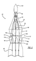
Figure 1 is a front view of a stent-graft having a bare stent portion in an open position and a plurality of trigger wires extending along the exterior of the stent-graft constraining first and second diameter reducing connectors; -
Figure 2 is a front view of the stent graft showing the bare stents being constrained at their proximal ends by the trigger wires; -
Figure 3 is a top view of one of the diameter reducing connectors; -
Figure 4 is a side view of the trigger wires being threaded through graft material of the stent-graft; -
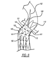
Figures 5-9 illustrate the staged deployment of the stent-graft within a body vessel with the trigger wires being withdrawn distally to release the bare stents and the diameter reducing connectors. -
Figure 10 illustrates another embodiment of a stent graft; -
Figure 11 illustrates yet another embodiment of a stent graft; and -
Figure 12 illustrates yet another embodiment of a stent graft. - The components in the drawings are not necessarily to scale, emphasis instead being placed upon illustrating the principles of the teachings herein.
- Throughout this specification, the terms "distal" and "distally" refer to a position, direction, or orientation that is generally away from the heart. Accordingly, the terms "proximal" and "proximally" refer to a position, direction, or orientation that is generally toward, or closer to the heart.
- The terms "endoluminal device" and "endovascular device" refer to or describe objects that can be placed inside a vessel, a lumen or a body passageway in a human or animal body. A lumen, vessel, or a body passageway can be a naturally occurring lumen or a lumen created by surgical intervention. As used in this specification, the terms "lumen" or "body passageway" are intended to have a broad meaning and encompasses any duct (e.g., natural or iatrogenic) within the human body and can include blood vessels, respiratory ducts, gastrointestinal ducts, and the like. Thus, "Endoluminal devices" or "endoluminal prosthesis" describe devices that can be placed inside one of these lumens.
- The term "fenestration" refers to an opening in a structure through which fluid can pass. The term "fenestration window" refers to a portion of a device comprising a substantially fluid impenetrable covering through which a fenestration can be opened or created by piercing, cutting, tearing, or the like.
- The term "stent" means any device or structure that adds rigidity, expansion force or support to a prosthesis or body lumen. A stent is used to obtain and/or maintain the patency of the body passageway while maintaining the integrity of the passageway. In addition, the stent may be used to form a fluid seal against the body lumen. The stent may be coated with a polymeric material, for example, by immersion in liquid polymer or any other method known to one of skill in the art. The stent may be located on the exterior of the device, the interior of the device, or both. A stent may be self-expanding, balloon-expandable or may have characteristics of both.
- The term "graft" or "graft material" describes an object, device, or structure that is joined to or that is capable of being joined to a body part to enhance, repair, or replace a portion or a function of that body part. A graft by itself or with the addition of other elements, such as structural components, e.g. stents, can form an endoluminal/endovascular device commonly referred to as a "stent-graft." The graft may comprise a single material, or a composite blend of materials. These materials may be in the form of a woven fabric, a laminate, etc. Referring now to the figures,
Figures 1 and2 illustrate an embodiment of adelivery system 100 including a dilator ornose cone 102 disposed at a proximal end thereof. Thenose cone 102 is attached to a proximal end of acannula 106, and the distal end of thecannula 106 is attached to acatheter 104. Anendoluminal prosthesis 112, which is shown in this embodiment as a stent-graft, is disposed about thecannula 106. The stent-graft 112 can be in the form of a bifurcated body, with a mainproximal portion 114, anintermediate portion 115, a firstdistal leg portion 116 and a seconddistal leg portion 118. Thedistal leg portions bifurcation point 119 disposed near the distal end of theintermediate portion 115. - The stent-
graft 112 includes atubular graft material 120 attached to a support frame or structure comprising a plurality ofstents stents stents stents discreet stent rings graft 120, in another embodiment the stent rings may be formed as a single monolithic structure that extends and wraps around thegraft 120 in a helical shape from the proximal end of thegraft 120 to the distal end of thegraft 120. - The
stent 131 can be in the form of aproximal sealing stent 131 and disposed at theproximal portion 114 and along the internal surface of the stent-graft 112, so that theproximal portion 114 can be generally free from stent structure on the outer surface. Thestents 130 can be disposed around the remainder of the stent-graft 112 on the exterior surface thereof so that thestents 130 are exposed. Thestents 130 can have a generally sharp construction, if desired, to promote tissue ingrowth of thestents 130 when the stent-graft 112 has been installed, thereby limiting migration of the stent-graft 112. - The stent-
graft 112 can further include a plurality ofbare stents 110 extending from the proximal end of the stent-graft 112. Thebare stents 110 can be made of a material similar to thestents bare stents 110 are biased to spring outward upon release from a compressed or constrained condition, as further described below, for assisting in the installation of the stent-graft 112 within the anatomy. The outward force of thebare stents 110 exerts a force on the body cavity, thereby limiting instances of the migration of the stent-graft 112 and acting as an anchor for the stent-graft 112 during installation. - The
bare stents 110 can extend from the distal end of the stent-graft 112. - Returning to
Figure 1 , a plurality ofdiameter reducing connectors 140, which may be formed by a plurality ofloops 141 defined by sutures, wire loops or the like, are attached to the bends of thestents graft material 120. In one embodiment, thediameter reducing connectors 140a are attached to the circumferentially adjacent distal bends of the proximal sealingstent 131, and theconnectors 140b are attached to the circumferentially adjacent distal bends of thestent 130a that is longitudinally adjacent the proximal sealingstent 131. - With reference to
Figure 3 , theconnector 140 comprises theloops 141. Theloops 141 can be coupled to each other atends loops 141 atpoint 141b can be attached to thegraft material 120 to hold one end of theloop 141 to the stent-graft 112. Theloop 141 atend 141a can be coupled to theadjacent loop 141 via atrigger wire 150 extending through theends 141a ofadjacent loops 141. As will be further described below, when thetrigger wire 150 is retracted distally from theloops 141 of theconnector 140, theloops 141 will be de-coupled from each other and allow the stent-graft 112 to expand at that location. - The
connectors 140 can, in other embodiments, be attached toadditional stents 130 along the length of the stent-graft 112, if desired. Additionally or alternatively, theconnectors 140 can be attached at the proximal end of the stent-graft 112 to thebare stents 110 or the proximal bends of the sealingstent 131. - While the
connectors 140 have been described as being attached, generally, to the distal bends of thestents stents stents stents stents - Note that while only one side of the stent-
graft 112 is shown inFigures 1 and2 , thedeployment device 100 may be constructed in a similar manner on the opposite side that is not shown. - With reference again to
Figures 1 and2 , the stent-graft 112 further includes a plurality oftriggers wires 150 that extend in a generally longitudinal direction along the perimeter of the stent-graft 112. Thetrigger wires 150 may be a suture, a wire made from a titanium alloy, such as Nitinol, or other flexible elongate mono- or multifilament member of suitable tensile strength. Thetrigger wires 150 can extend from a distal handle (not shown) through a lumen of thecatheter 104 and exiting the catheter atholes 152, where they can then extend along the circumferential perimeters of thedistal leg 116, theintermediate portion 115, and theproximal portion 114. Thetrigger wires 150 can further extend into thenose cone 102. - More specifically, the
trigger wires 150 can be routed into ahousing 154 located at the proximal end of thecannula 106 and distally from thenose cone 102. Thewires 150 then extend out of thehousing 154, before entering the interior of thenose cone 102, where the proximal ends of thetrigger wires 150 will terminate. - The extension of the
trigger wires 150 between thehousing 154 and thenose cone 102 defines a holdingportion 156 of each of thetrigger wires 150. The holdingportions 156 extend through the apices of thebare stents 110, thereby retaining the apices of thebare stents 110 to thenose cone 102. As further described below, pulling on thetrigger wires 150 to remove them from thenose cone 102 will cause thebare stents 110 to be released to expand outwardly. - The
trigger wires 150 extend longitudinally along the perimeter of the stent-graft 112, as described above. Thetrigger wires 150 can be laterally held in place bysuture loops 160, or other loop-like structure, disposed along the length of thestent 112, as well as by theloops 141 of thediameter reducing connectors 140. More specifically, thetrigger wires 150 can be held laterally in place byends 141a of theloops 141. - In another form, as shown in
Figure 4 , thetrigger wires 150 can be threaded in and out of thegraft material 120 in the longitudinal direction, thereby limiting the use ofsuture loops 160 attached to the stent-graft 112. In this form, thetrigger wires 150 will still extend through theloops 141 of thediameter reducing connectors 140 as shown inFigures 1 and2 . - The stent-
graft 112 can be configured to transfer from a compressed delivery state to an expanded installed state. Expansion of the stent-graft 112 will be described in further detail below. To compress the stent-graft 112 for delivery into the patient, the stent-graft 112 can be circumferentially compressed along its length for delivery in a manner known in the art. - The
diameter reducing connectors 140 are attached around the circumference of the stent-graft 112 in the desired locations along the length of the stent-graft 112. Theloops 141 are generally attached to the graft at theirends 141b via a suture or other known fixing mechanism for attaching a loop to graft material. The ends 141a of theloops 141 are coupled to each other via one of thetrigger wires 150 extending through theends 141a of circumferentiallyadjacent loops 141. When linked fully around the circumference of the stent-graft 112, the diameter of thediameter reducing connectors 140 is less than the diameter of the stent-graft 112 in its expanded state. Thus, by connecting each of theloops 141, the diameter of the stent-graft 112 is reduced. With theconnectors 140 being attached to the stent-graft 112 around thestents 130 and/or 131, thestents stents connectors 140 so that release of theconnectors 140 will allow the stent-graft 112 to expand outwardly. - The stent-
graft 112 can also be held in a compressed state by compressing the graft and inserting it into a sheath or other tubular member as known in the art. Thedistal legs graft 112 longitudinally adjacent thereto, can be generally compressed in this manner ifdiameter reducing connectors 140 are not used in these areas. - The
bare stents 110 are compressed by bending them inward toward thenose cone 102. As described above, thebare stents 110 are retained at thenose cone 102 by the holdingportions 156 defined by thetrigger wires 150 between thehousing 154 and thenose cone 102. Thebare stents 110 are, similar to thestents bare stents 110 will exert a radially outward force on the holdingportion 156 and will expand outwardly upon release from the holdingportions 156. - By running the
trigger wires 150 along the perimeter of the stent-graft 112, thecannula 106 can be made relatively thin compared to a cannula that would include trigger wires extending therethrough for holding the bare stents. Thus, when the stent-graft 112 is compressed as described above, the stent-graft 112 can have a smaller compressed size relative to a graft having a thicker cannula. The smaller compressed diameter of stent-graft 112 can allow for a smaller overall delivery system, thereby reducing trauma to the patient during the procedure. When in the compressed condition, the stent-graft 112 may tend to have a folded wave-like cross-section as known in the art. In this condition, thetrigger wires 150, extending along the perimeter of the stent-graft 112 instead of through thecannula 106, can be disposed within the folds of the compressed stent-graft 112, thereby generally not increasing the outer profile of the stent-graft 112. - Moreover, the use of the
same trigger wires 150 for thebare stents 110 and thediameter reducing connectors 140 reduces the overall profile of the stent-graft 112, as well, because the number of total trigger wires is reduced. - With the
trigger wires 150 extending from thenose cone 102 to thehousing 154 and then to the perimeter of the stent-graft 112, the radially outward force of the stent-graft 112 that is exerted against thetrigger wires 150 can cause thetrigger wires 150 themselves to exert a radially outward force on thenose cone 102 and thehousing 154. As such, thenose cone 102 and thehousing 154 are preferably made from a material that has a low friction with the material of thetrigger wire 150 to reduce the friction on thetrigger wire 150 when it is pulled to release thebare stents 110. - In one preferred form, as shown in
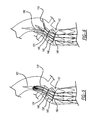
Figure 10 , the stent-graft 112 is constrained at its proximal region in the following configuration. The stent-graft 112 includes astent 230 disposed on the outer surface of the stent-graft 112. Astent 231 is disposed proximally adjacent thestent 230 and is disposed on the inner surface of the stent-graft 112. Astent 232 is disposed at the proximal end of the stent-graft 112 and is also disposed on the inner surface of the stent-graft 112. One set ofconnectors 240 is disposed at the distal bends of thestent 230. Another set ofconnectors 241 is disposed at the middle of thestent 231. Thestent 232 can be free from direct restraint by connectors. - The number of sets of connectors and the locations of the connectors on the stents define the shape of the stent-
graft 112, as shown inFigures 10 . The area of the stent-graft 112 betweenconnectors diameter portion 250. The area from the most proximal set ofconnectors 241 to the proximal end of the stent-graft 112 defines a taperedportion 260 that increases in diameter proximally. - In another preferred form, as shown in
Figure 11 , the stent-graft 112 is constrained at its proximal region in the following configuration. The stent-graft 112 includes astent 330 disposed on the outer surface of the stent-graft 112. Astent 331 is disposed proximally adjacent thestent 330 and is disposed on the inner surface of the stent-graft 112. Astent 332 is disposed at the proximal end of the stent-graft 112 and is also disposed on the inner surface of the stent-graft 112. One set ofconnectors 340 are disposed at the distal bends of thestent 230. A second set ofconnectors 341 are disposed at the middle of thestent 331. A third set ofconnectors 342 are disposed at middle of thestent 332. - The number of sets of connectors and the locations of the connectors on the stents defines the shape of the stent-
graft 112, as shown inFigure 11 . The area of the stent-graft 112 betweenconnectors diameter portion 350, which is longer than reduceddiameter portion 250 described above. The area from the most proximal set ofconnectors 342 to the proximal end of the stent-graft 112 defines a taperedportion 360 that increases in diameter proximally, and has a shorter length than taperedportion 260 described above. - In another preferred form, as shown in
Figure 12 , the stent-graft 112 is constrained at its proximal region in the following configuration. The stent-graft 112 includes astent 430 disposed on the outer surface of the stent-graft 112. Astent 431 is disposed proximally adjacent thestent 430 and is disposed on the outer surface of the stent-graft 112, as well. Astent 432 is disposed at the proximal end of the stent-graft 112 and is disposed on the inner surface of the stent-graft 112. One set ofconnectors 440 are disposed at the distal bends of thestent 230. A second set ofconnectors 441 are disposed at the middle of thestent 331. A third set ofconnectors 442 are disposed at distal end of thestent 432. - The number of sets of connectors and the locations of the connectors on the stents defines the shape of the stent-
graft 112, as shown inFigure 12 . The area of the stent-graft 112 betweenconnectors diameter portion 350, which is longer than reduceddiameter portion 250 and shorter than reduceddiameter portion 350, described above. The area from the most proximal set ofconnectors 442 to the proximal end of the stent-graft 112 defines a taperedportion 460 that increases in diameter proximally, and has a shorter length than taperedportion 260 and a longer length than taperedportion 360 described above. - The above described stent-
grafts 112 ofFigures 10-12 can utilize thetrigger wires 150 described above as well as the other delivery components described above, to constrain and thereafter release the stent-grafts shown inFigures 10-12 . - It will be appreciated that other combinations of stents on the inside or outside of the stent-graft can be used, as well as the location on the stents where the connectors are disposed. Furthermore, the number of stents that can be constrained, as well as the number of connectors can also vary, depending on the needs of the user.
- Having described the general structure of the stent-
graft 112, the delivery and deployment of the stent-graft 112 will now be described. -
Figures 5-9 illustrate a deployment process for thesystem 100. while a tubular stent graft is shown, the process applies in analogy to branched stent grafts as, for example, shown inFigs. 10-12 . First, thedelivery system 100 is inserted into a patient's vasculature percutaneously and advanced over a guidewire to the treatment site in the thoracic arch or the like using the Seldinger technique, which is well known in the art. Thedelivery system 100 may have radiopaque markers disposed on a retention sheath to indicate circumferential and longitudinal orientation of thedelivery system 100. - Initially, the stent-
graft 112 is restrained in a reduced diameter, compressed or collapsed configuration against thecannula 106 by the retention sheath or the like. Once thedelivery device 100 is advanced to the treatment site, the sheath is withdrawn and the proximal end of the stent-stent-graft 112 is allowed to expand partially outward against the vessel wall. Additionally, thebare stents 110 are exposed within the vessel. The sheath can be retracted further relative to the stent-graft 112, to expose the remainder of the stent-graft 112, as shown inFigure 5 . - The stent-
graft 112 can then be expanded in a sequential manner due to the relationship between thetrigger wires 150 and the stent-graft 112. - In one form, one of the
trigger wires 150 can be retracted in the distal direction a first amount to release thebare stent 110 that is retained to thetrigger wire 150 at the holdingportion 156. Thebare stent 110 that has been released will then expand radially outward and into engagement with the vessel wall. This can be repeated for the remainder of thetrigger wires 150 to release the remainder of thebare stents 110, thereby allowing the remainder of thebare stents 110 to expand radially outward and into engagement with the vessel wall. By releasing thebare stents 110 in this manner, thebare stents 110 can anchor the stent-graft 112 to the vessel wall to limit migration of the stent-graft 112 within the vessel, as shown inFigures 6 and7 . - Following release of the
bare stents 110, one of thetrigger wires 150 can be retracted distally a second amount to release theloops 141 of thediameter reducing connecter 140 longitudinally adjacent thebare stents 110, such as theconnector 140 that is constraining the sealingstent 131. Releasing theloops 141 that are coupled to thetrigger wire 150 will allow theloops 141 to become de-coupled to each other, allowing the stent-graft 112 to expand outward a first amount. This can be repeated for the remainder of thetrigger wires 150 to release the remainder of theloops 141 that are constrained by these trigger wires. Thus, the stent-graft 112 will be allowed to expand radially outward in the area of the sealingstent 131 to engage the vessel wall in that area, as shown inFigure 8 . - Following the release of the stent-
graft 112 in the area of the sealingstent 131, one of thetrigger wires 150 can be retracted distally an additional amount to release theloops 141 of thediameter reducing connector 140 located distally adjacent the sealingstent 131. Similar to the above, the stent-graft 112 will be expanded radially outward an additional amount in the location of thestent 130 that is constrained by theconnector 140. The remainder of thetrigger wires 150 can be sequentially retracted to release the remainder of theloops 141 to allow the stent-graft 112 to expand fully to engage the vessel wall in the area ofstent 130, as shown inFigure 9 . - The above process can be repeated for any remaining
stents 130 that are constrained. After each of thediameter reducing connectors 140 have been released and the stent-graft 112 has been expanded, thetrigger wires 150 can be retracted fully and out of engagement with the stent-graft 112, leaving the stent-graft 112 engaged with the vessel wall. - With the stent-
graft 112 engaged with the vessel wall and in the installed configuration, thecatheter 104,cannula 106, andnose cone 102 can be retracted from the vessel, along with the guidewire 10 and any other non-graft structure. The percutaneous procedure can then be concluded in a manner known in the art. - In another form, rather than first expanding the
bare stents 110 prior to expanding thesealing stent 131 and then thestent 130, the stent-graft 112 can be expanded along its length corresponding toindividual trigger wires 150. For example, asingle trigger wire 150 can be retracted along the length of the stent-graft 112, allowing thebare stent 110, sealingstent 131, andstent 130 to partially expand in the area of the retractedtrigger wire 150. Following retraction of thistrigger wire 150, anothertrigger wire 150 can be retracted, expanding thebare stent 110, sealingstent 131, andstent 130 an additional sequential amount. This can be repeated for the remainder of thetrigger wires 150. - It will be appreciated that the various sequential retractions of the
trigger wires 150 can be varied to suit the needs of the user, partially expanding the various portions of the stent-graft 112 by altering the order and distance in which thetrigger wires 150 are retracted. - The
trigger wires 150 can be retracted in any order. For example, thetrigger wires 150 can be retracted such that circumferentiallyadjacent trigger wires 150 are released in order. In another embodiment one of thetrigger wires 150 on one side of the stent-graft 112 can be retracted, followed by one of thetrigger wires 150 on the opposite side of the stent-graft 112. It will be appreciated that various sequences of trigger retraction can be performed to suit the needs of the user. - In the case where the releasable
bare stents 110 extend from the distal end of the stent-graft 112, withdrawing thetrigger wires 150 can first allow thestents bare stents 110. It will be appreciated that similar modifications to the order of releasing the various components of the stent-graft can be realized by altering the positioning of the components along the length of the stent-graft 112, as well as altering the direction to withdraw thetrigger wires 150, if desired. - While preferred embodiments have been described, it should be understood that the invention is not so limited, and modifications may be made without departing from the invention. For example features of a given embodiment may be implemented in a different embodiment, be it as an addition or a substitution for a different feature.
- All optional and preferred features and modification of the described embodiments and dependent claims are usable in all aspects of the invention taught herein. Furthermore, the individual features of the dependent claims, as well as all optional and preferred features and modification of the described embodiments are combinable and interchangeable with one another.
- The disclosure in United States patent application numbers
61/746,036 13/828,402
Claims (15)
- A system for deploying a stent-graft, the system comprising:an expandable stent-graft comprising:a tubular graft having a proximal portion including a proximal end, an intermediate portion, and a distal portion including a distal end;a first stent ring attached to the perimeter of the graft;a first releasable diameter reducing connector extending around the stent ring;a releasable stent portion extending from at least one of the proximal and distal ends at least partially axially from an end having apices at a proximal end thereof;a retractable trigger wire disposed adjacent a surface of the stent-graft extending longitudinally along the length of the stent-graft, the trigger wire releasably attached to the releasable diameter reducing connector and the releasable stent portion.
- The system of claim 1, wherein the trigger wire is attached to the graft along its length.
- The system of claim 1 or 2, further comprising a cannula extending through a lumen of the stent-graft and the trigger wire is releasably attached to a proximal portion of the cannula and attached to a distal portion of the cannula.
- The system of one of claims 1-3, wherein the diameter reducing connector includes a plurality of loops.
- The system of claim 4, wherein the trigger wire extends through two of the plurality of loops.
- The system of one of claims 1-5, wherein the trigger wire is longitudinally threaded through the graft along its length.
- The system of one of claims 1-6, wherein the diameter reducing connector extends around a distal portion of the stent ring.
- The system one of claims 1-7, wherein the diameter reducing connector extends around a middle portion of the stent ring.
- The system of one of claims 1-8, wherein the diameter reducing connector extends around a proximal portion of the stent ring.
- A system according to one of claims 1-9 comprising:a second stent ring attached to the perimeter of the graft; anda second diameter reducing connector extending around the second stent ring.
- The system of claim 10, wherein the tubular graft surrounds the first stent ring, the second stent ring surrounds the tubular graft, and the second stent ring is disposed distally from the first stent ring.
- The system of claim 10 or 11, wherein the graft includes a proximal portion, a first distal leg portion, and second distal leg portion and the trigger wire extends along the first distal leg portion.
- The system of claim 12, wherein the first distal leg portion is longer than the second distal leg portion.
- The system of one of claims 10-13 further comprising a third diameter reducing connector attached to the proximal end of the graft and adjacent a distal end of the bare stent.
- The system of one of claims 1-14 configured to perform the steps of:delivering, in a compressed condition, the system to a body vessel;withdrawing the trigger wire a first longitudinal distance along the length of the stent-graft;in response to withdrawing the trigger wire a first longitudinal distance, releasing the releasable stent portion to expand the bare stent portion in a radial direction and toward engagement with a wall of the body vessel;in response to releasing the releasable bare stent portion, withdrawing the trigger wire a second longitudinal distance along the length of the stent-graft; andin response to withdrawing the trigger wire a second longitudinal distance, releasing the stent ring to expand the stent ring in a radial direction toward engagement with the wall of the body vessel.
Applications Claiming Priority (2)
| Application Number | Priority Date | Filing Date | Title |
|---|---|---|---|
| US201261746036P | 2012-12-26 | 2012-12-26 | |
| US13/828,402 US10350096B2 (en) | 2012-12-26 | 2013-03-14 | Expandable stent-graft system having diameter reducing connectors |
Publications (2)
| Publication Number | Publication Date |
|---|---|
| EP2749251A1 true EP2749251A1 (en) | 2014-07-02 |
| EP2749251B1 EP2749251B1 (en) | 2016-07-20 |
Family
ID=49841610
Family Applications (1)
| Application Number | Title | Priority Date | Filing Date |
|---|---|---|---|
| EP13275330.2A Active EP2749251B1 (en) | 2012-12-26 | 2013-12-20 | Expandable stent-graft system having diameter reducing connectors |
Country Status (2)
| Country | Link |
|---|---|
| US (1) | US10350096B2 (en) |
| EP (1) | EP2749251B1 (en) |
Cited By (20)
| Publication number | Priority date | Publication date | Assignee | Title |
|---|---|---|---|---|
| WO2016168176A1 (en) * | 2015-04-13 | 2016-10-20 | Cook Medical Technologies Llc | Axial lock and release stent deployment system |
| EP3069696B1 (en) * | 2015-03-16 | 2017-09-27 | Cook Medical Technologies LLC | Medical device assembly with constriction mechanism |
| WO2018156847A1 (en) * | 2017-02-24 | 2018-08-30 | Bolton Medical, Inc. | Delivery system and method to radially constrict a stent graft |
| WO2019219728A1 (en) | 2018-05-15 | 2019-11-21 | Tessarek Joerg | Multi-lumen implant |
| WO2020072861A1 (en) * | 2018-10-05 | 2020-04-09 | W. L. Gore & Associates, Inc. | Constraining mechanisms and associated methods |
| EP3733124A4 (en) * | 2017-12-29 | 2021-01-13 | Hangzhou Endonom Medtech Co., Ltd | Aortic stent graft capable of step-by-step release |
| US10987235B2 (en) | 2016-06-13 | 2021-04-27 | Aortica Corporation | Systems, devices, and methods for marking and/or reinforcing fenestrations in prosthetic implants |
| US11000359B2 (en) | 2016-08-02 | 2021-05-11 | Aortica Corporation | Systems, devices, and methods for coupling a prosthetic implant to a fenestrated body |
| US11219540B2 (en) | 2017-02-24 | 2022-01-11 | Bolton Medical, Inc. | Radially adjustable stent graft delivery system and method of use |
| US11278390B2 (en) | 2017-02-24 | 2022-03-22 | Bolton Medical, Inc. | Stent graft with fenestration lock and methods of use |
| US11291572B2 (en) | 2017-02-24 | 2022-04-05 | Bolton Medical, Inc. | Delivery system for radially constricting a stent graft and method of use |
| US11351025B2 (en) | 2017-02-24 | 2022-06-07 | Bolton Medical, Inc. | Vascular prosthesis with fenestration ring and methods of use |
| US11369466B2 (en) | 2017-02-24 | 2022-06-28 | Bolton Medical, Inc. | Vascular prosthesis with moveable fenestration and method of use |
| US11376145B2 (en) | 2017-10-31 | 2022-07-05 | Bolton Medical, Inc. | Distal torque component, delivery system and method of using same |
| US11399929B2 (en) | 2017-02-24 | 2022-08-02 | Bolton Medical, Inc. | Vascular prosthesis with crimped adapter and methods of use |
| US11413177B2 (en) | 2017-02-24 | 2022-08-16 | Bolton Medical, Inc. | Stent graft delivery system with constricted sheath and method of use |
| US11478349B2 (en) | 2017-09-25 | 2022-10-25 | Bolton Medical, Inc. | Systems, devices, and methods for coupling a prosthetic implant to a fenestrated body |
| US11491003B2 (en) | 2017-02-24 | 2022-11-08 | Bolton Medical, Inc. | Constrainable stent graft, delivery system and methods of use |
| EP4218688A1 (en) * | 2017-04-28 | 2023-08-02 | Cook Medical Technologies LLC | Systems and methods for adjusting the diameter of an endoluminal prosthesis and an endoluminal prosthesis configured for the same |
| US11730584B2 (en) | 2017-02-24 | 2023-08-22 | Bolton Medical, Inc. | System and method to radially constrict a stent graft |
Families Citing this family (36)
| Publication number | Priority date | Publication date | Assignee | Title |
|---|---|---|---|---|
| US8137398B2 (en) * | 2008-10-13 | 2012-03-20 | Medtronic Ventor Technologies Ltd | Prosthetic valve having tapered tip when compressed for delivery |
| WO2011064782A2 (en) | 2009-11-30 | 2011-06-03 | Endospan Ltd. | Multi-component stent-graft system for implantation in a blood vessel with multiple branches |
| US10213329B2 (en) | 2011-08-12 | 2019-02-26 | W. L. Gore & Associates, Inc. | Evertable sheath devices, systems, and methods |
| ES2577010T3 (en) | 2011-08-12 | 2016-07-12 | W.L. Gore & Associates, Inc. | Devices to approximate the cross-sectional profile of a vasculature that has ramifications |
| US9877858B2 (en) | 2011-11-14 | 2018-01-30 | W. L. Gore & Associates, Inc. | External steerable fiber for use in endoluminal deployment of expandable devices |
| US9782282B2 (en) | 2011-11-14 | 2017-10-10 | W. L. Gore & Associates, Inc. | External steerable fiber for use in endoluminal deployment of expandable devices |
| EP2785277B1 (en) * | 2011-12-04 | 2017-04-05 | Endospan Ltd. | Branched stent-graft system |
| US9687371B2 (en) | 2012-02-14 | 2017-06-27 | W. L. Gore & Associates, Inc. | Endoprosthesis having aligned legs for ease of cannulation |
| US9375308B2 (en) | 2012-03-13 | 2016-06-28 | W. L. Gore & Associates, Inc. | External steerable fiber for use in endoluminal deployment of expandable devices |
| US8968384B2 (en) * | 2012-04-27 | 2015-03-03 | Medtronic Vascular, Inc. | Circumferentially constraining sutures for a stent-graft |
| WO2013171730A1 (en) | 2012-05-15 | 2013-11-21 | Endospan Ltd. | Stent-graft with fixation elements that are radially confined for delivery |
| CN107456297A (en) | 2013-01-08 | 2017-12-12 | 恩多斯潘有限公司 | The minimum of Stent Graft Migration during implantation |
| US9763819B1 (en) | 2013-03-05 | 2017-09-19 | W. L. Gore & Associates, Inc. | Tapered sleeve |
| US9987155B1 (en) | 2013-03-07 | 2018-06-05 | W. L. Gore & Associates, Inc. | Implantable medical devices and related delivery systems |
| US9668892B2 (en) | 2013-03-11 | 2017-06-06 | Endospan Ltd. | Multi-component stent-graft system for aortic dissections |
| WO2015075708A1 (en) | 2013-11-19 | 2015-05-28 | Endospan Ltd. | Stent system with radial-expansion locking |
| US9907641B2 (en) | 2014-01-10 | 2018-03-06 | W. L. Gore & Associates, Inc. | Implantable intraluminal device |
| US10966850B2 (en) | 2014-03-06 | 2021-04-06 | W. L. Gore & Associates, Inc. | Implantable medical device constraint and deployment apparatus |
| US9833346B2 (en) | 2014-04-04 | 2017-12-05 | W. L. Gore & Associates, Inc. | Deployment handle for a medical device deployment system |
| US9974675B2 (en) | 2014-04-04 | 2018-05-22 | W. L. Gore & Associates, Inc. | Delivery and deployment systems for bifurcated stent grafts |
| US10478324B2 (en) | 2014-08-12 | 2019-11-19 | W. L. Gore & Associates, Inc. | Handle for medical device deployment |
| CN106029005B (en) | 2014-12-18 | 2018-01-19 | 恩都思潘有限公司 | The Endovascular stent-graft of horizontal conduit with tired resistance |
| US10034785B1 (en) | 2015-10-13 | 2018-07-31 | W. L. Gore & Associates, Inc. | Single site access aortic aneurysm repair method |
| CN105726165B (en) * | 2016-05-09 | 2017-07-28 | 中国人民解放军南京军区福州总医院 | A kind of sustainer overlay film branch stent |
| CA3030781C (en) | 2016-08-05 | 2022-07-19 | W. L. Gore & Associates, Inc. | Integrated medical device constraining lumen |
| ES2810401T3 (en) | 2016-08-24 | 2021-03-08 | Gore & Ass | Expandable Medical Device Sleeves |
| AU2016256777B1 (en) * | 2016-11-10 | 2017-04-20 | Cook Medical Technologies Llc | Temporary diameter reduction constraint arrangement for a stent graft in combination with a stent graft |
| US11191632B2 (en) | 2016-11-10 | 2021-12-07 | Cook Medical Technologies Llc | Temporary diameter reduction constraint arrangement for a stent graft in combination with a stent graft |
| DE102016122223A1 (en) | 2016-11-18 | 2018-05-24 | Bentley Innomed Gmbh | Multi-lumen implant |
| US11213415B2 (en) | 2017-02-14 | 2022-01-04 | W. L. Gore & Associates, Inc. | Medical device delivery systems and methods |
| CA3054838A1 (en) | 2017-03-01 | 2018-09-07 | Adam POWER | Looped wire for advanced stent grafts and methods of using same |
| CN109567981A (en) * | 2017-09-29 | 2019-04-05 | 微创心脉医疗科技(上海)有限公司 | Support system and its conveying device, rear release structure and bracket |
| ES2960532T3 (en) | 2017-10-11 | 2024-03-05 | Gore & Ass | Implantable medical device restraint and deployment apparatus |
| JP2021525581A (en) | 2018-05-31 | 2021-09-27 | エンドロジックス リミテッド ライアビリティ カンパニー | Stent graft system with constraints in the channel and methods thereof |
| US20220023073A1 (en) * | 2018-12-13 | 2022-01-27 | Kawasumi Laboratories, Inc. | Gastrointestinal stent |
| GB2605559B (en) | 2021-01-07 | 2023-04-05 | Cook Medical Technologies Llc | Stent graft |
Citations (4)
| Publication number | Priority date | Publication date | Assignee | Title |
|---|---|---|---|---|
| EP1136044A1 (en) * | 1999-10-04 | 2001-09-26 | Kanji Inoue | Method of folding transplanting instrument and transplanting instrument |
| US20040138734A1 (en) * | 2001-04-11 | 2004-07-15 | Trivascular, Inc. | Delivery system and method for bifurcated graft |
| US20060004433A1 (en) * | 2004-06-16 | 2006-01-05 | Cook Incorporated | Thoracic deployment device and stent graft |
| US20070043425A1 (en) * | 2005-08-18 | 2007-02-22 | William A. Cook Australia Pty Ltd. | Assembly of stent grafts |
Family Cites Families (10)
| Publication number | Priority date | Publication date | Assignee | Title |
|---|---|---|---|---|
| US7147657B2 (en) * | 2003-10-23 | 2006-12-12 | Aptus Endosystems, Inc. | Prosthesis delivery systems and methods |
| CA2486390C (en) | 2002-05-29 | 2011-01-04 | William A. Cook Australia Pty. Ltd. | Trigger wire system for a prosthesis deployment device |
| US7722657B2 (en) | 2002-08-23 | 2010-05-25 | William A. Cook Australia Pty. Ltd. | Asymmetric stent graft attachment |
| US7993383B2 (en) | 2004-09-28 | 2011-08-09 | William A. Cook Australia Pty. Ltd. | Device for treating aortic dissection |
| WO2008140796A1 (en) | 2007-05-11 | 2008-11-20 | William A. Cook Australia Pty. Ltd. | Stent grafts for the thoracic aorta |
| GB2475494B (en) * | 2009-11-18 | 2011-11-23 | Cook William Europ | Stent graft and introducer assembly |
| US8163007B2 (en) | 2008-02-08 | 2012-04-24 | Cook Medical Technologies Llc | Stent designs for use with one or more trigger wires |
| AU2010319903B2 (en) | 2009-10-29 | 2013-07-11 | Cook Medical Technologies Llc | Stent delivery system with nitinol trigger wire |
| US9757263B2 (en) | 2009-11-18 | 2017-09-12 | Cook Medical Technologies Llc | Stent graft and introducer assembly |
| US9198787B2 (en) | 2010-12-31 | 2015-12-01 | Cook Medical Technologies Llc | Conformable prosthesis delivery system and method for deployment thereof |
-
2013
- 2013-03-14 US US13/828,402 patent/US10350096B2/en active Active
- 2013-12-20 EP EP13275330.2A patent/EP2749251B1/en active Active
Patent Citations (4)
| Publication number | Priority date | Publication date | Assignee | Title |
|---|---|---|---|---|
| EP1136044A1 (en) * | 1999-10-04 | 2001-09-26 | Kanji Inoue | Method of folding transplanting instrument and transplanting instrument |
| US20040138734A1 (en) * | 2001-04-11 | 2004-07-15 | Trivascular, Inc. | Delivery system and method for bifurcated graft |
| US20060004433A1 (en) * | 2004-06-16 | 2006-01-05 | Cook Incorporated | Thoracic deployment device and stent graft |
| US20070043425A1 (en) * | 2005-08-18 | 2007-02-22 | William A. Cook Australia Pty Ltd. | Assembly of stent grafts |
Cited By (27)
| Publication number | Priority date | Publication date | Assignee | Title |
|---|---|---|---|---|
| EP3069696B1 (en) * | 2015-03-16 | 2017-09-27 | Cook Medical Technologies LLC | Medical device assembly with constriction mechanism |
| US10292847B2 (en) | 2015-03-16 | 2019-05-21 | Cook Medical Technologies Llc | System and method for the sequential expansion of a medical device |
| WO2016168176A1 (en) * | 2015-04-13 | 2016-10-20 | Cook Medical Technologies Llc | Axial lock and release stent deployment system |
| US10813778B2 (en) | 2015-04-13 | 2020-10-27 | Cook Medical Technologies Llc | Axial lock and release stent deployment system |
| US10987235B2 (en) | 2016-06-13 | 2021-04-27 | Aortica Corporation | Systems, devices, and methods for marking and/or reinforcing fenestrations in prosthetic implants |
| US11918450B2 (en) | 2016-08-02 | 2024-03-05 | Bolton Medical, Inc. | Systems, devices, and methods for coupling a prosthetic implant to a fenestrated body |
| US11000359B2 (en) | 2016-08-02 | 2021-05-11 | Aortica Corporation | Systems, devices, and methods for coupling a prosthetic implant to a fenestrated body |
| US11291572B2 (en) | 2017-02-24 | 2022-04-05 | Bolton Medical, Inc. | Delivery system for radially constricting a stent graft and method of use |
| US11491003B2 (en) | 2017-02-24 | 2022-11-08 | Bolton Medical, Inc. | Constrainable stent graft, delivery system and methods of use |
| WO2018156847A1 (en) * | 2017-02-24 | 2018-08-30 | Bolton Medical, Inc. | Delivery system and method to radially constrict a stent graft |
| US11219540B2 (en) | 2017-02-24 | 2022-01-11 | Bolton Medical, Inc. | Radially adjustable stent graft delivery system and method of use |
| US11278390B2 (en) | 2017-02-24 | 2022-03-22 | Bolton Medical, Inc. | Stent graft with fenestration lock and methods of use |
| US11801129B2 (en) | 2017-02-24 | 2023-10-31 | Bolton Medical, Inc. | Vascular prosthesis with fenestration ring and methods of use |
| US11351025B2 (en) | 2017-02-24 | 2022-06-07 | Bolton Medical, Inc. | Vascular prosthesis with fenestration ring and methods of use |
| US11369466B2 (en) | 2017-02-24 | 2022-06-28 | Bolton Medical, Inc. | Vascular prosthesis with moveable fenestration and method of use |
| US11730584B2 (en) | 2017-02-24 | 2023-08-22 | Bolton Medical, Inc. | System and method to radially constrict a stent graft |
| US11399929B2 (en) | 2017-02-24 | 2022-08-02 | Bolton Medical, Inc. | Vascular prosthesis with crimped adapter and methods of use |
| US11413177B2 (en) | 2017-02-24 | 2022-08-16 | Bolton Medical, Inc. | Stent graft delivery system with constricted sheath and method of use |
| US11547584B2 (en) | 2017-02-24 | 2023-01-10 | Bolton Medical, Inc. | Delivery system and method to radially constrict a stent graft |
| EP4218688A1 (en) * | 2017-04-28 | 2023-08-02 | Cook Medical Technologies LLC | Systems and methods for adjusting the diameter of an endoluminal prosthesis and an endoluminal prosthesis configured for the same |
| US11478349B2 (en) | 2017-09-25 | 2022-10-25 | Bolton Medical, Inc. | Systems, devices, and methods for coupling a prosthetic implant to a fenestrated body |
| US11376145B2 (en) | 2017-10-31 | 2022-07-05 | Bolton Medical, Inc. | Distal torque component, delivery system and method of using same |
| EP3733124A4 (en) * | 2017-12-29 | 2021-01-13 | Hangzhou Endonom Medtech Co., Ltd | Aortic stent graft capable of step-by-step release |
| WO2019219728A1 (en) | 2018-05-15 | 2019-11-21 | Tessarek Joerg | Multi-lumen implant |
| AU2019355984B2 (en) * | 2018-10-05 | 2022-09-08 | W. L. Gore & Associates, Inc. | Constraining mechanisms and associated methods |
| JP7297881B2 (en) | 2018-10-05 | 2023-06-26 | ダブリュ.エル.ゴア アンド アソシエイツ,インコーポレイティド | Restraint mechanism and related methods |
| WO2020072861A1 (en) * | 2018-10-05 | 2020-04-09 | W. L. Gore & Associates, Inc. | Constraining mechanisms and associated methods |
Also Published As
| Publication number | Publication date |
|---|---|
| US10350096B2 (en) | 2019-07-16 |
| EP2749251B1 (en) | 2016-07-20 |
| US20140180378A1 (en) | 2014-06-26 |
Similar Documents
| Publication | Publication Date | Title |
|---|---|---|
| EP2749251B1 (en) | Expandable stent-graft system having diameter reducing connectors | |
| JP6100995B2 (en) | Shape-adapted prosthesis supply system and arrangement method thereof | |
| EP2344072B1 (en) | Stent graft and introducer for deploying said stent graft in a curved lumen | |
| US8337546B2 (en) | Mobile external coupling for branch vessel connection | |
| CA2487131C (en) | Thoracic stent graft introducer | |
| JP5087397B2 (en) | Device and method for delivering an intravascular stent-graft having a portion that is not longitudinally supported | |
| US7722657B2 (en) | Asymmetric stent graft attachment | |
| US10335265B2 (en) | Ring on a closed web stent-graft for use in tip capture | |
| JP6261339B2 (en) | Apparatus and method for placement of a graft or graft system | |
| US20100268318A1 (en) | Prosthesis for Antegrade Deployment | |
| JP2020508086A (en) | Sheath contracted stent graft delivery system and method of use | |
| US10758387B2 (en) | Endovascular stent graft assembly and delivery device | |
| US20070168013A1 (en) | Vascular graft and deployment system | |
| US20110251664A1 (en) | Short Legged Bifurcated Stent Graft Distal Capture Element and Method | |
| EP2745813A1 (en) | Preloaded wire for endoluminal device | |
| US20080228255A1 (en) | Positionable Stent-Graft Delivery System and Method | |
| US20110270379A1 (en) | Mobile External Coupling for Branch Vessel Connection | |
| CN106456327B (en) | Push-pull medical device delivery system | |
| WO2007084724A2 (en) | Vascular graft and deployment system | |
| EP2985007A2 (en) | Preloaded wire for endoluminal device | |
| EP2586405B1 (en) | Releasable top cap assembly | |
| US20100268317A1 (en) | Stent Graft Restraining Mechanism for a Delivery System (Catheter) | |
| US9763816B2 (en) | Endoluminal prosthesis delivery system and method | |
| JP2023133439A (en) | Low profile delivery system with lock wire lumen |
Legal Events
| Date | Code | Title | Description |
|---|---|---|---|
| 17P | Request for examination filed |
Effective date: 20131220 |
|
| AK | Designated contracting states |
Kind code of ref document: A1 Designated state(s): AL AT BE BG CH CY CZ DE DK EE ES FI FR GB GR HR HU IE IS IT LI LT LU LV MC MK MT NL NO PL PT RO RS SE SI SK SM TR |
|
| AX | Request for extension of the european patent |
Extension state: BA ME |
|
| PUAI | Public reference made under article 153(3) epc to a published international application that has entered the european phase |
Free format text: ORIGINAL CODE: 0009012 |
|
| R17P | Request for examination filed (corrected) |
Effective date: 20141217 |
|
| RBV | Designated contracting states (corrected) |
Designated state(s): AL AT BE BG CH CY CZ DE DK EE ES FI FR GB GR HR HU IE IS IT LI LT LU LV MC MK MT NL NO PL PT RO RS SE SI SK SM TR |
|
| GRAP | Despatch of communication of intention to grant a patent |
Free format text: ORIGINAL CODE: EPIDOSNIGR1 |
|
| INTG | Intention to grant announced |
Effective date: 20160209 |
|
| GRAS | Grant fee paid |
Free format text: ORIGINAL CODE: EPIDOSNIGR3 |
|
| GRAA | (expected) grant |
Free format text: ORIGINAL CODE: 0009210 |
|
| AK | Designated contracting states |
Kind code of ref document: B1 Designated state(s): AL AT BE BG CH CY CZ DE DK EE ES FI FR GB GR HR HU IE IS IT LI LT LU LV MC MK MT NL NO PL PT RO RS SE SI SK SM TR |
|
| REG | Reference to a national code |
Ref country code: GB Ref legal event code: FG4D |
|
| RIN1 | Information on inventor provided before grant (corrected) |
Inventor name: ROEDER, BLAYNE A. |
|
| REG | Reference to a national code |
Ref country code: CH Ref legal event code: EP |
|
| REG | Reference to a national code |
Ref country code: IE Ref legal event code: FG4D |
|
| REG | Reference to a national code |
Ref country code: AT Ref legal event code: REF Ref document number: 813387 Country of ref document: AT Kind code of ref document: T Effective date: 20160815 |
|
| REG | Reference to a national code |
Ref country code: DE Ref legal event code: R096 Ref document number: 602013009553 Country of ref document: DE |
|
| REG | Reference to a national code |
Ref country code: LT Ref legal event code: MG4D |
|
| REG | Reference to a national code |
Ref country code: NL Ref legal event code: MP Effective date: 20160720 |
|
| REG | Reference to a national code |
Ref country code: AT Ref legal event code: MK05 Ref document number: 813387 Country of ref document: AT Kind code of ref document: T Effective date: 20160720 |
|
| PG25 | Lapsed in a contracting state [announced via postgrant information from national office to epo] |
Ref country code: NO Free format text: LAPSE BECAUSE OF FAILURE TO SUBMIT A TRANSLATION OF THE DESCRIPTION OR TO PAY THE FEE WITHIN THE PRESCRIBED TIME-LIMIT Effective date: 20161020 Ref country code: HR Free format text: LAPSE BECAUSE OF FAILURE TO SUBMIT A TRANSLATION OF THE DESCRIPTION OR TO PAY THE FEE WITHIN THE PRESCRIBED TIME-LIMIT Effective date: 20160720 Ref country code: RS Free format text: LAPSE BECAUSE OF FAILURE TO SUBMIT A TRANSLATION OF THE DESCRIPTION OR TO PAY THE FEE WITHIN THE PRESCRIBED TIME-LIMIT Effective date: 20160720 Ref country code: IS Free format text: LAPSE BECAUSE OF FAILURE TO SUBMIT A TRANSLATION OF THE DESCRIPTION OR TO PAY THE FEE WITHIN THE PRESCRIBED TIME-LIMIT Effective date: 20161120 Ref country code: LT Free format text: LAPSE BECAUSE OF FAILURE TO SUBMIT A TRANSLATION OF THE DESCRIPTION OR TO PAY THE FEE WITHIN THE PRESCRIBED TIME-LIMIT Effective date: 20160720 Ref country code: IT Free format text: LAPSE BECAUSE OF FAILURE TO SUBMIT A TRANSLATION OF THE DESCRIPTION OR TO PAY THE FEE WITHIN THE PRESCRIBED TIME-LIMIT Effective date: 20160720 Ref country code: FI Free format text: LAPSE BECAUSE OF FAILURE TO SUBMIT A TRANSLATION OF THE DESCRIPTION OR TO PAY THE FEE WITHIN THE PRESCRIBED TIME-LIMIT Effective date: 20160720 Ref country code: NL Free format text: LAPSE BECAUSE OF FAILURE TO SUBMIT A TRANSLATION OF THE DESCRIPTION OR TO PAY THE FEE WITHIN THE PRESCRIBED TIME-LIMIT Effective date: 20160720 |
|
| PG25 | Lapsed in a contracting state [announced via postgrant information from national office to epo] |
Ref country code: PT Free format text: LAPSE BECAUSE OF FAILURE TO SUBMIT A TRANSLATION OF THE DESCRIPTION OR TO PAY THE FEE WITHIN THE PRESCRIBED TIME-LIMIT Effective date: 20161121 Ref country code: ES Free format text: LAPSE BECAUSE OF FAILURE TO SUBMIT A TRANSLATION OF THE DESCRIPTION OR TO PAY THE FEE WITHIN THE PRESCRIBED TIME-LIMIT Effective date: 20160720 Ref country code: AT Free format text: LAPSE BECAUSE OF FAILURE TO SUBMIT A TRANSLATION OF THE DESCRIPTION OR TO PAY THE FEE WITHIN THE PRESCRIBED TIME-LIMIT Effective date: 20160720 Ref country code: PL Free format text: LAPSE BECAUSE OF FAILURE TO SUBMIT A TRANSLATION OF THE DESCRIPTION OR TO PAY THE FEE WITHIN THE PRESCRIBED TIME-LIMIT Effective date: 20160720 Ref country code: LV Free format text: LAPSE BECAUSE OF FAILURE TO SUBMIT A TRANSLATION OF THE DESCRIPTION OR TO PAY THE FEE WITHIN THE PRESCRIBED TIME-LIMIT Effective date: 20160720 Ref country code: BE Free format text: LAPSE BECAUSE OF FAILURE TO SUBMIT A TRANSLATION OF THE DESCRIPTION OR TO PAY THE FEE WITHIN THE PRESCRIBED TIME-LIMIT Effective date: 20160720 Ref country code: SE Free format text: LAPSE BECAUSE OF FAILURE TO SUBMIT A TRANSLATION OF THE DESCRIPTION OR TO PAY THE FEE WITHIN THE PRESCRIBED TIME-LIMIT Effective date: 20160720 Ref country code: GR Free format text: LAPSE BECAUSE OF FAILURE TO SUBMIT A TRANSLATION OF THE DESCRIPTION OR TO PAY THE FEE WITHIN THE PRESCRIBED TIME-LIMIT Effective date: 20161021 |
|
| REG | Reference to a national code |
Ref country code: DE Ref legal event code: R097 Ref document number: 602013009553 Country of ref document: DE |
|
| PG25 | Lapsed in a contracting state [announced via postgrant information from national office to epo] |
Ref country code: RO Free format text: LAPSE BECAUSE OF FAILURE TO SUBMIT A TRANSLATION OF THE DESCRIPTION OR TO PAY THE FEE WITHIN THE PRESCRIBED TIME-LIMIT Effective date: 20160720 Ref country code: EE Free format text: LAPSE BECAUSE OF FAILURE TO SUBMIT A TRANSLATION OF THE DESCRIPTION OR TO PAY THE FEE WITHIN THE PRESCRIBED TIME-LIMIT Effective date: 20160720 |
|
| PLBE | No opposition filed within time limit |
Free format text: ORIGINAL CODE: 0009261 |
|
| STAA | Information on the status of an ep patent application or granted ep patent |
Free format text: STATUS: NO OPPOSITION FILED WITHIN TIME LIMIT |
|
| PG25 | Lapsed in a contracting state [announced via postgrant information from national office to epo] |
Ref country code: DK Free format text: LAPSE BECAUSE OF FAILURE TO SUBMIT A TRANSLATION OF THE DESCRIPTION OR TO PAY THE FEE WITHIN THE PRESCRIBED TIME-LIMIT Effective date: 20160720 Ref country code: SM Free format text: LAPSE BECAUSE OF FAILURE TO SUBMIT A TRANSLATION OF THE DESCRIPTION OR TO PAY THE FEE WITHIN THE PRESCRIBED TIME-LIMIT Effective date: 20160720 Ref country code: BG Free format text: LAPSE BECAUSE OF FAILURE TO SUBMIT A TRANSLATION OF THE DESCRIPTION OR TO PAY THE FEE WITHIN THE PRESCRIBED TIME-LIMIT Effective date: 20161020 Ref country code: CZ Free format text: LAPSE BECAUSE OF FAILURE TO SUBMIT A TRANSLATION OF THE DESCRIPTION OR TO PAY THE FEE WITHIN THE PRESCRIBED TIME-LIMIT Effective date: 20160720 Ref country code: SK Free format text: LAPSE BECAUSE OF FAILURE TO SUBMIT A TRANSLATION OF THE DESCRIPTION OR TO PAY THE FEE WITHIN THE PRESCRIBED TIME-LIMIT Effective date: 20160720 |
|
| 26N | No opposition filed |
Effective date: 20170421 |
|
| REG | Reference to a national code |
Ref country code: CH Ref legal event code: PL |
|
| PG25 | Lapsed in a contracting state [announced via postgrant information from national office to epo] |
Ref country code: SI Free format text: LAPSE BECAUSE OF FAILURE TO SUBMIT A TRANSLATION OF THE DESCRIPTION OR TO PAY THE FEE WITHIN THE PRESCRIBED TIME-LIMIT Effective date: 20160720 |
|
| PG25 | Lapsed in a contracting state [announced via postgrant information from national office to epo] |
Ref country code: MC Free format text: LAPSE BECAUSE OF FAILURE TO SUBMIT A TRANSLATION OF THE DESCRIPTION OR TO PAY THE FEE WITHIN THE PRESCRIBED TIME-LIMIT Effective date: 20160720 |
|
| REG | Reference to a national code |
Ref country code: FR Ref legal event code: ST Effective date: 20170831 |
|
| PG25 | Lapsed in a contracting state [announced via postgrant information from national office to epo] |
Ref country code: LI Free format text: LAPSE BECAUSE OF NON-PAYMENT OF DUE FEES Effective date: 20161231 Ref country code: FR Free format text: LAPSE BECAUSE OF NON-PAYMENT OF DUE FEES Effective date: 20170102 Ref country code: LU Free format text: LAPSE BECAUSE OF NON-PAYMENT OF DUE FEES Effective date: 20161220 Ref country code: CH Free format text: LAPSE BECAUSE OF NON-PAYMENT OF DUE FEES Effective date: 20161231 |
|
| PG25 | Lapsed in a contracting state [announced via postgrant information from national office to epo] |
Ref country code: HU Free format text: LAPSE BECAUSE OF FAILURE TO SUBMIT A TRANSLATION OF THE DESCRIPTION OR TO PAY THE FEE WITHIN THE PRESCRIBED TIME-LIMIT; INVALID AB INITIO Effective date: 20131220 |
|
| PG25 | Lapsed in a contracting state [announced via postgrant information from national office to epo] |
Ref country code: CY Free format text: LAPSE BECAUSE OF FAILURE TO SUBMIT A TRANSLATION OF THE DESCRIPTION OR TO PAY THE FEE WITHIN THE PRESCRIBED TIME-LIMIT Effective date: 20160720 Ref country code: MK Free format text: LAPSE BECAUSE OF FAILURE TO SUBMIT A TRANSLATION OF THE DESCRIPTION OR TO PAY THE FEE WITHIN THE PRESCRIBED TIME-LIMIT Effective date: 20160720 |
|
| PG25 | Lapsed in a contracting state [announced via postgrant information from national office to epo] |
Ref country code: MT Free format text: LAPSE BECAUSE OF NON-PAYMENT OF DUE FEES Effective date: 20161220 |
|
| PG25 | Lapsed in a contracting state [announced via postgrant information from national office to epo] |
Ref country code: TR Free format text: LAPSE BECAUSE OF FAILURE TO SUBMIT A TRANSLATION OF THE DESCRIPTION OR TO PAY THE FEE WITHIN THE PRESCRIBED TIME-LIMIT Effective date: 20160720 Ref country code: AL Free format text: LAPSE BECAUSE OF FAILURE TO SUBMIT A TRANSLATION OF THE DESCRIPTION OR TO PAY THE FEE WITHIN THE PRESCRIBED TIME-LIMIT Effective date: 20160720 |
|
| P01 | Opt-out of the competence of the unified patent court (upc) registered |
Effective date: 20230602 |
|
| PGFP | Annual fee paid to national office [announced via postgrant information from national office to epo] |
Ref country code: GB Payment date: 20231108 Year of fee payment: 11 |
|
| PGFP | Annual fee paid to national office [announced via postgrant information from national office to epo] |
Ref country code: IE Payment date: 20231128 Year of fee payment: 11 Ref country code: DE Payment date: 20231108 Year of fee payment: 11 |