EP2708254A1 - Container for nasal administration - Google Patents
Container for nasal administration Download PDFInfo
- Publication number
- EP2708254A1 EP2708254A1 EP12785294.5A EP12785294A EP2708254A1 EP 2708254 A1 EP2708254 A1 EP 2708254A1 EP 12785294 A EP12785294 A EP 12785294A EP 2708254 A1 EP2708254 A1 EP 2708254A1
- Authority
- EP
- European Patent Office
- Prior art keywords
- plunger
- medical fluid
- nasal cavity
- moving amount
- regulation member
- Prior art date
- Legal status (The legal status is an assumption and is not a legal conclusion. Google has not performed a legal analysis and makes no representation as to the accuracy of the status listed.)
- Granted
Links
Images


Classifications
-
- A—HUMAN NECESSITIES
- A61—MEDICAL OR VETERINARY SCIENCE; HYGIENE
- A61M—DEVICES FOR INTRODUCING MEDIA INTO, OR ONTO, THE BODY; DEVICES FOR TRANSDUCING BODY MEDIA OR FOR TAKING MEDIA FROM THE BODY; DEVICES FOR PRODUCING OR ENDING SLEEP OR STUPOR
- A61M31/00—Devices for introducing or retaining media, e.g. remedies, in cavities of the body
-
- A—HUMAN NECESSITIES
- A61—MEDICAL OR VETERINARY SCIENCE; HYGIENE
- A61M—DEVICES FOR INTRODUCING MEDIA INTO, OR ONTO, THE BODY; DEVICES FOR TRANSDUCING BODY MEDIA OR FOR TAKING MEDIA FROM THE BODY; DEVICES FOR PRODUCING OR ENDING SLEEP OR STUPOR
- A61M11/00—Sprayers or atomisers specially adapted for therapeutic purposes
- A61M11/006—Sprayers or atomisers specially adapted for therapeutic purposes operated by applying mechanical pressure to the liquid to be sprayed or atomised
- A61M11/007—Syringe-type or piston-type sprayers or atomisers
-
- A—HUMAN NECESSITIES
- A61—MEDICAL OR VETERINARY SCIENCE; HYGIENE
- A61M—DEVICES FOR INTRODUCING MEDIA INTO, OR ONTO, THE BODY; DEVICES FOR TRANSDUCING BODY MEDIA OR FOR TAKING MEDIA FROM THE BODY; DEVICES FOR PRODUCING OR ENDING SLEEP OR STUPOR
- A61M15/00—Inhalators
- A61M15/08—Inhaling devices inserted into the nose
-
- A—HUMAN NECESSITIES
- A61—MEDICAL OR VETERINARY SCIENCE; HYGIENE
- A61M—DEVICES FOR INTRODUCING MEDIA INTO, OR ONTO, THE BODY; DEVICES FOR TRANSDUCING BODY MEDIA OR FOR TAKING MEDIA FROM THE BODY; DEVICES FOR PRODUCING OR ENDING SLEEP OR STUPOR
- A61M3/00—Medical syringes, e.g. enemata; Irrigators
-
- A—HUMAN NECESSITIES
- A61—MEDICAL OR VETERINARY SCIENCE; HYGIENE
- A61M—DEVICES FOR INTRODUCING MEDIA INTO, OR ONTO, THE BODY; DEVICES FOR TRANSDUCING BODY MEDIA OR FOR TAKING MEDIA FROM THE BODY; DEVICES FOR PRODUCING OR ENDING SLEEP OR STUPOR
- A61M5/00—Devices for bringing media into the body in a subcutaneous, intra-vascular or intramuscular way; Accessories therefor, e.g. filling or cleaning devices, arm-rests
- A61M5/178—Syringes
- A61M5/31—Details
- A61M5/315—Pistons; Piston-rods; Guiding, blocking or restricting the movement of the rod or piston; Appliances on the rod for facilitating dosing ; Dosing mechanisms
- A61M5/31511—Piston or piston-rod constructions, e.g. connection of piston with piston-rod
-
- A—HUMAN NECESSITIES
- A61—MEDICAL OR VETERINARY SCIENCE; HYGIENE
- A61M—DEVICES FOR INTRODUCING MEDIA INTO, OR ONTO, THE BODY; DEVICES FOR TRANSDUCING BODY MEDIA OR FOR TAKING MEDIA FROM THE BODY; DEVICES FOR PRODUCING OR ENDING SLEEP OR STUPOR
- A61M5/00—Devices for bringing media into the body in a subcutaneous, intra-vascular or intramuscular way; Accessories therefor, e.g. filling or cleaning devices, arm-rests
- A61M5/178—Syringes
- A61M5/31—Details
- A61M5/315—Pistons; Piston-rods; Guiding, blocking or restricting the movement of the rod or piston; Appliances on the rod for facilitating dosing ; Dosing mechanisms
- A61M5/31565—Administration mechanisms, i.e. constructional features, modes of administering a dose
- A61M5/31576—Constructional features or modes of drive mechanisms for piston rods
- A61M5/31578—Constructional features or modes of drive mechanisms for piston rods based on axial translation, i.e. components directly operatively associated and axially moved with plunger rod
- A61M5/3158—Constructional features or modes of drive mechanisms for piston rods based on axial translation, i.e. components directly operatively associated and axially moved with plunger rod performed by axially moving actuator operated by user, e.g. an injection button
-
- A—HUMAN NECESSITIES
- A61—MEDICAL OR VETERINARY SCIENCE; HYGIENE
- A61M—DEVICES FOR INTRODUCING MEDIA INTO, OR ONTO, THE BODY; DEVICES FOR TRANSDUCING BODY MEDIA OR FOR TAKING MEDIA FROM THE BODY; DEVICES FOR PRODUCING OR ENDING SLEEP OR STUPOR
- A61M5/00—Devices for bringing media into the body in a subcutaneous, intra-vascular or intramuscular way; Accessories therefor, e.g. filling or cleaning devices, arm-rests
- A61M5/178—Syringes
- A61M5/31—Details
- A61M5/315—Pistons; Piston-rods; Guiding, blocking or restricting the movement of the rod or piston; Appliances on the rod for facilitating dosing ; Dosing mechanisms
- A61M5/31511—Piston or piston-rod constructions, e.g. connection of piston with piston-rod
- A61M2005/31516—Piston or piston-rod constructions, e.g. connection of piston with piston-rod reducing dead-space in the syringe barrel after delivery
-
- A—HUMAN NECESSITIES
- A61—MEDICAL OR VETERINARY SCIENCE; HYGIENE
- A61M—DEVICES FOR INTRODUCING MEDIA INTO, OR ONTO, THE BODY; DEVICES FOR TRANSDUCING BODY MEDIA OR FOR TAKING MEDIA FROM THE BODY; DEVICES FOR PRODUCING OR ENDING SLEEP OR STUPOR
- A61M5/00—Devices for bringing media into the body in a subcutaneous, intra-vascular or intramuscular way; Accessories therefor, e.g. filling or cleaning devices, arm-rests
- A61M5/178—Syringes
- A61M5/31—Details
- A61M5/315—Pistons; Piston-rods; Guiding, blocking or restricting the movement of the rod or piston; Appliances on the rod for facilitating dosing ; Dosing mechanisms
- A61M5/31511—Piston or piston-rod constructions, e.g. connection of piston with piston-rod
- A61M2005/31518—Piston or piston-rod constructions, e.g. connection of piston with piston-rod designed to reduce the overall size of an injection device, e.g. using flexible or pivotally connected chain-like rod members
-
- A—HUMAN NECESSITIES
- A61—MEDICAL OR VETERINARY SCIENCE; HYGIENE
- A61M—DEVICES FOR INTRODUCING MEDIA INTO, OR ONTO, THE BODY; DEVICES FOR TRANSDUCING BODY MEDIA OR FOR TAKING MEDIA FROM THE BODY; DEVICES FOR PRODUCING OR ENDING SLEEP OR STUPOR
- A61M2210/00—Anatomical parts of the body
- A61M2210/06—Head
- A61M2210/0618—Nose
-
- A—HUMAN NECESSITIES
- A61—MEDICAL OR VETERINARY SCIENCE; HYGIENE
- A61M—DEVICES FOR INTRODUCING MEDIA INTO, OR ONTO, THE BODY; DEVICES FOR TRANSDUCING BODY MEDIA OR FOR TAKING MEDIA FROM THE BODY; DEVICES FOR PRODUCING OR ENDING SLEEP OR STUPOR
- A61M3/00—Medical syringes, e.g. enemata; Irrigators
- A61M3/02—Enemata; Irrigators
- A61M3/0233—Enemata; Irrigators characterised by liquid supply means, e.g. from pressurised reservoirs
- A61M3/0254—Enemata; Irrigators characterised by liquid supply means, e.g. from pressurised reservoirs the liquid being pumped
- A61M3/0262—Enemata; Irrigators characterised by liquid supply means, e.g. from pressurised reservoirs the liquid being pumped manually, e.g. by squeezing a bulb
-
- A—HUMAN NECESSITIES
- A61—MEDICAL OR VETERINARY SCIENCE; HYGIENE
- A61M—DEVICES FOR INTRODUCING MEDIA INTO, OR ONTO, THE BODY; DEVICES FOR TRANSDUCING BODY MEDIA OR FOR TAKING MEDIA FROM THE BODY; DEVICES FOR PRODUCING OR ENDING SLEEP OR STUPOR
- A61M5/00—Devices for bringing media into the body in a subcutaneous, intra-vascular or intramuscular way; Accessories therefor, e.g. filling or cleaning devices, arm-rests
- A61M5/178—Syringes
- A61M5/31—Details
- A61M5/315—Pistons; Piston-rods; Guiding, blocking or restricting the movement of the rod or piston; Appliances on the rod for facilitating dosing ; Dosing mechanisms
- A61M5/31501—Means for blocking or restricting the movement of the rod or piston
- A61M5/31505—Integral with the syringe barrel, i.e. connected to the barrel so as to make up a single complete piece or unit
Definitions
- the present invention relates to a nasal cavity administration container for administering a medical fluid to nasal cavities.
- a nasal cavity administration container is used to administer a medical fluid to both the nasal cavities.
- a predetermined dose of the medical fluid is administered to the one of the nasal cavities.
- the nasal cavity administration container being inserted in the other nasal cavity, the remaining medical fluid is administered to the other nasal cavity.
- the nasal cavity administration container administer a predetermined dose of the medical fluid (e.g., one half for each) to each nasal cavity easily and appropriately.
- PTD 1 Japanese Patent Laying-Open No. 2001-137344
- the present invention is to provide a nasal cavity administration container that can achieve easier and more appropriate administration when administering a medical fluid to both the nasal cavities.
- a nasal cavity administration container includes a body section including a medical fluid storage section provided with a spray nozzle on one end side and an opening on the other end side and a plunger to be inserted into the medical fluid storage section from the one end side through the opening, the plunger being provided with a pressing part on the other end side, and a plunger moving amount regulation member including a stopper arranged between the pressing part and the opening and being engaged with the body section, an engagement with the body section being relieved only in a state where the pressing part abuts on the stopper.
- the plunger is pushed into the medical fluid storage section, thereby moving forward until the pressing part abuts on the stopper.
- the plunger is further pushed into the medical fluid storage section with the plunger moving amount regulation member detached from the body section.
- a first fitted part is provided on an outer circumferential surface of the body section
- the plunger moving amount regulation member has a second fitted part to be fitted to the first fitted part in a state where the plunger moving amount regulation member is attached to the body section, and a movement of the plunger moving amount regulation member attached to the body section relative to the body section is regulated by a fit between the first fitted part and the second fitted part.
- the plunger moving amount regulation member has a grasping part to be engaged with the plunger so as to externally grasp the plunger, a constricted part is provided on the other end side of the plunger, and in a state where the pressing part abuts on the stopper, the grasping part is positioned to be opposed to the constricted part, and an engagement of the plunger moving amount regulation member with the plunger is relieved.
- the plunger has a first abutting part relieving an engagement between the first fitted part and the second fitted part with the pressing part abutting on the stopper.
- the plunger has a second abutting part located between the stopper and the pressing part in the state where the plunger moving amount regulation member is engaged with the body section, the plunger is inserted into the medical fluid storage section to cause the second abutting part to abut on one of the stopper and the body section, and the plunger is pushed into the medical fluid storage section, thereby relieving an abutment of the plunger on one of the stopper and the body section.
- a nasal cavity administration container that can achieve easier and more appropriate administration when administering a medical fluid to both the nasal cavities can be obtained.
- a nasal cavity administration container 100 Referring to Figs. 1 to 6 , the structure of a nasal cavity administration container 100 according to the present embodiment will be described.
- Fig. 1 is a perspective view showing nasal cavity administration container 100.
- Fig. 2 is a front view showing nasal cavity administration container 100, which is an arrow view taken along an arrow 11 in Fig. 1 .
- Fig. 3 is a side view showing nasal cavity administration container 100, which is an arrow view taken along an arrow III in Fig. 1 .
- nasal cavity administration container 100 is provided with a body section 30 and a plunger moving amount regulation member 40.
- Body section 30 includes a medical fluid storage section 10 and a plunger 20.
- Medical fluid storage section 10 is composed of a barrel 11 and a finger clip part 14.
- Barrel 11 has a substantially cylindrical hollow shape. Plunger 20 and a gasket 28 which will be described later are inserted into barrel 11.
- One end of barrel 11 constitutes one end 12 of medical fluid storage section 10.
- a nozzle 12N (syringe nozzle) is formed on the one end 12 side of medical fluid storage section 10.
- a spray nozzle 12M (see Fig. 1 ) communicating with the inside of barrel 11 by way of nozzle 12N is attached to the one end 12 side of medical fluid storage section 10.
- spray nozzle 12M illustrated in Fig. 1 is not illustrated in the other drawings, spray nozzle 12M shall be attached to barrel 11 in each of the present and subsequent embodiments.
- Barrel 11 and spray nozzle 12M may be formed integrally, or may be formed as separate units and then attached to each other as in the present embodiment.
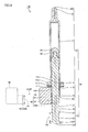
- Fig. 4 is an arrow cross sectional view taken along the line IV-IV in Fig. 2 .
- an annular flange part 11R bulging outwardly in a cylinder radial direction is provided on the other end side of barrel 11.
- an opening 11H is formed on the inner side relative to flange part 11R.
- Finger clip part 14 is provided with a notch 14U corresponding to the outer shape of flange part 11R (see Fig. 1 as well). Notch 14U communicates with an opening 14J extending through toward the outer edge of finger clip part 14. Finger clip part 14 is attached to flange part 11R by frictional engagement while grasping flange part 11R.
- Finger clip part 14 is also provided with an opening 14H (see Fig. 4 ) through which plunger 20 and gasket 28 pass.
- a suspended part 15 is provided to hang down continuously with opening 14H.
- Suspended part 15 has a substantially halved cylindrical shape. The leading end of suspended part 15 in the hanging down direction constitutes the other end 13 of medical fluid storage section 10.
- An opening 13H through which plunger 20 and gasket 28 pass is formed on the other end 13 side of medical fluid storage section 10.
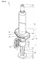
- Fig. 5 is a perspective view showing a state where nasal cavity administration container 100 has been disassembled partly (plunger moving amount regulation member 40 has been detached from body section 30).
- plunger 20 has a substantially rod-like shape.
- Plunger 20 has four ribs 21 having a thin plate shape.
- ribs 21 extend in the longitudinal direction of plunger 20 from one end 22 (see Fig. 4 ) toward the other end 23 (see Fig. 4 ) of plunger 20. As shown in Fig. 5 , four ribs 21 are arranged at 90° intervals, and stand up toward the outside perpendicularly to the longitudinal direction of plunger 20.
- gasket 28 made of rubber is provided on one end 22 of plunger 20.
- a disc-like pressing part 23P is provided on the other end 23 of plunger 20.
- plunger 20 is inserted into medical fluid storage section 10 (barrel 11) together with gasket 28 from the one end 22 side through opening 13H of medical fluid storage section 10 (barrel 11).
- a constricted part 26 is provided on the other end 23 side of plunger 20 according to the present embodiment.
- the height of constricted part 26 (a dimension of plunger 20 in the direction perpendicular to the longitudinal direction of plunger 20 (in the horizontal direction on the sheet of Fig. 4 )) is established relatively low as compared with a leading end 24 in the direction in which each rib 21 stands up. In other words, each rib 21 is constricted at constricted part 26.
- Each of four ribs 21 is provided with an abutting part 25 (second abutting part) between leading end 24 and constricted part 26. It is noted that abutting part 25 may be provided according to necessity. When abutting part 25 is provided between leading end 24 and constricted part 26, abutting part 25 is provided to project from leading end 24 of rib 21 in the direction perpendicular to the longitudinal direction of plunger 20. The leading end of abutting part 25 in the projecting direction is positioned at a slightly outer side (in the horizontal direction on the sheet of Fig. 4 ) relative to the inner diameter of suspended part 15 of finger clip part 14. Further details of abutting part 25 and constricted part 26 will be described later.
- plunger moving amount regulation member 40 includes a grip 41 and stoppers 42 and 43. Stoppers 42 and 43 are formed continuously with an end of grip 41 having a flat plate-like shape. Stoppers 42 and 43 are formed symmetrically on the opposite sides of grip 41, and present a substantially halved cylindrical shape as a whole.
- Fig. 6 is an arrow cross sectional view taken along the line VI-VI in Fig. 5 .
- a grasping part 42E is provided at the leading end of stopper 42.
- Grasping part 42E is formed to be folded back from the leading end of stopper 42 toward the inner side.
- a grasping part 43E is provided at the leading end of stopper 43.
- Grasping part 43E is also formed to be folded back from the leading end of stopper 43 toward the inner side.
- a distance L1 between grasping parts 42E and 43E is provided to be slightly smaller than a distance L2 between leading ends 24 in the standing direction of ribs 21 (distance L1 ⁇ distance L2).
- Plunger moving amount regulation member 40 can be engaged with plunger 20 so as to grip ribs 21 (leading ends 24 of ribs 21) of plunger 20 from the outside by means of grasping parts 42E and 43E.
- distance L1 between grasping parts 42E and 43E is provided to be slightly wider than a distance L3 between the leading ends of constricted parts 26 (distance L1 > distance L3).
- a dimension H1 of grasping parts 42E and 43E in the longitudinal direction is provided to be slightly smaller than a dimension H2 of constricted part 26 of plunger 20 in the same direction (dimension H1 ⁇ dimension H2).
- long slots 40M may be provided in the inner circumferential side of stoppers 42 and 43.
- Long slots 40M are formed to correspond to the shape of ribs 21 of plunger 20.
- leading ends 24 of ribs 21 and long slots 40M are fitted to each other in the state where plunger moving amount regulation member 40 is attached to plunger 20 (in the state where grasping parts 42E and 43E of plunger moving amount regulation member 40 and ribs 21 of plunger 20 are engaged with each other), a rotational movement of plunger moving amount regulation member 40 relative to plunger 20 can be restrained or prevented.
- a rib 40Y (see Fig. 6 ) may be provided in long slots 40M (the operation of rib 40Y will be described later).
- gasket 28 is inserted into barrel 11 through opening 11H of barrel 11.
- a rubber cap or the like may be attached to one end 12 of barrel 11, and in this state, barrel 11 may be filled up with a medical fluid.
- finger clip part 14 is attached to flange part 11R of barrel 11. As described above, finger clip part 14 is attached to flange part 11R by frictional engagement while holding flange part 11R.
- plunger moving amount regulation member 40 is attached to plunger 20 (see arrow AR40).
- plunger moving amount regulation member 40 is brought closer to finger clip part 14. Since grasping parts 42E and 43E are engaged with ribs 21, stoppers 42 and 43 of plunger moving amount regulation member 40 are slightly elastically deformed to the outside.
- plunger moving amount regulation member 40 may be attached to body section 30 (plunger 20) in the following manner. First, plunger 20 is inserted into medical fluid storage section 10 to cause abutting part 25 of plunger 20 to abut on the other end 13 of suspended part 15. In the state where the relative positional relationship between medical fluid storage section 10 and plunger 20 is fixed, constricted parts 26 of plunger 20 and stoppers 42, 43 of plunger moving amount regulation member 40 are arranged to be opposed to each other. Plunger moving amount regulation member 40 and plunger 20 are arranged adjacent to each other such that stoppers 42 and 43 of plunger moving amount regulation member 40 surround the outer circumferences of constricted parts 26.
- plunger 20 is moved away from medical fluid storage section 10.
- stoppers 42 and 43 are slightly elastically deformed to the outside.
- abutting part 25 has completely passed by the inner side of stoppers 42 and 43, a state similar to that shown in Fig. 4 is obtained.
- Nasal cavity administration container 100 may be assembled in this manner.
- stoppers 42 and 43 of plunger moving amount regulation member 40 are located between pressing part 23P of plunger 20 and opening 13H of medical fluid storage section 10 (finger clip part 14).
- Plunger moving amount regulation member 40 is engaged with body section 30 (specifically, ribs 21 of plunger 20) by means of grasping parts 42E and 43E.
- Abutting part 25 of plunger 20 is located between stoppers 42, 43 of plunger moving amount regulation member 40 and pressing part 23P of plunger 20.
- this structure allows the state where plunger moving amount regulation member 40 is engaged with body section 30 to be relieved only in the state where pressing part 23P of plunger 20 abuts on stoppers 42, 43 of plunger moving amount regulation member 40 (the state shown in Fig. 9 ).
- Nasal cavity administration container 100 transitions sequentially among the respective states of a first administration preparatory state S11 (see Fig. 7 ), a first administration start state S12 (see Fig. 8 ), a first administration completion state S 13 (see Fig. 9 ), a second administration preparatory state S 14 (see Fig. 10 ), a second administration start state S15 (see Fig. 11 ), and a second administration completion state S16 (see Fig. 12 ).
- a first administration of a medical fluid 60 is carried out through first administration preparatory state S11, first administration start state S12 and first administration completion state S13.
- a second administration of medical fluid 60 is carried out through second administration preparatory state S 14, second administration start state S15 and second administration completion state S16.
- nasal cavity administration container 100 is injected (or sucked) into nasal cavity administration container 100 as assembled from the nozzle 12N side (the state shown in Fig. 7 ).
- nasal cavity administration container 100 transitions to first administration preparatory state S11.
- air 62 may enter medical fluid storage section 10 (barrel 11) on the one end 12 side.
- an operation called priming is carried out for the purpose of setting the dose of medical fluid 60 to be administered to a nasal cavity at a predetermined value and exhausting air having entered medical fluid storage section 10 (barrel 11) (according to necessity).
- plunger 20 is inserted into medical fluid storage section 10 (barrel 11) (see arrow AR1).
- Plunger 20 and gasket 28 enter barrel 11 while in sliding contact with the inside of barrel 11 until abutting part 25 of plunger 20 abuts on stoppers 42 and 43 of plunger moving amount regulation member 40.
- a rib (above-described rib 40Y in Fig. 6 ) to abut on abutting part 25 when plunger 20 is inserted into barrel 11 may be provided on the inner side of stoppers 42 and 43.
- stoppers 42 and 43 correspond to "one of stoppers 42, 43 and body section 30.”
- nasal cavity administration container 100 transitions to first administration start state S12.
- the air in medical fluid storage section 10 (barrel 11) is forced out of medical fluid storage section 10, and the dose of medical fluid 60 to be administered to a nasal cavity is set at the predetermined value (priming is carried out).
- spray nozzle 12M (see Fig. 1 ) attached to the nozzle 12N side is located in one of the nasal cavities.
- plunger 20 is strongly pushed into medical fluid storage section 10 (barrel 11) by means of pressing part 23P (see arrow AR2).
- Medical fluid 60 in medical fluid storage section 10 is sprayed through spray nozzle 12M (see Fig. 1 ) by the movement of gasket 28. A mist of medical fluid 60 is administered to one of the nasal cavities through spray nozzle 12M. Plunger 20 moves forward until pressing part 23P abuts on the lower ends of stoppers 42, 43 of plunger moving amount regulation member 40.
- grasping parts 42E and 43E of plunger moving amount regulation member 40 are positioned to be opposed to constricted parts 26 of plunger 20.
- the state where plunger moving amount regulation member 40 is engaged with plunger 20 (ribs 21) is relieved by the arrangement relationship between grasping parts 42E, 43E and constricted parts 26.
- plunger moving amount regulation member 40 is detached from body section 30 (the state shown in Fig. 10 ) as indicated by arrow AR3.
- nasal cavity administration container 100 transitions to second administration preparatory state S 14.
- plunger 20 is further pushed into medical fluid storage section 10 (barrel 11) by means of pressing part 23P (see arrow AR4). Plunger 20 moves forward inside medical fluid storage section 10. Gasket 28 is pushed by plunger 20, thereby further entering medical fluid storage section 10.
- a rib having a function similar to above-described rib 14Y may be provided on the inner side of suspended part 15 of finger clip part 14.
- abutting part 25 is engaged with this rib. Since abutting part 25 and this rib are engaged until compressive force stronger than prescribed is applied, stable spray into the nasal cavities can be accomplished under high pressure from the start of spraying.
- Medical fluid 60 in medical fluid storage section 10 is sprayed through spray nozzle 12M (see Fig. 1 ) by the movement of gasket 28.
- a mist of medical fluid 60 is administered through spray nozzle 12M to the other nasal cavity.
- Plunger 20 moves forward until gasket 28 abuts on the upper end in barrel 11.
- Plunger 20 may be formed to move forward until pressing part 23P abuts on the lower end (other end 13) of suspended part 15 of finger clip part 14.
- nasal cavity administration container 100 As described above, abutting part 25 is provided for plunger 20, and plunger moving amount regulation member 40 is attached to plunger 20 of body section 30.
- abutting part 25 of plunger 20 abuts on stoppers 42, 43 of plunger moving amount regulation member 40, nasal cavity administration container 100 can easily transition from first administration preparatory state S11 (see Fig. 7 ) to first administration start state S12 (see Fig. 8 ). It is noted that abutting part 25 may be provided according to necessity as described above.
- plunger moving amount regulation member 40 is engaged with body section 30 through first administration preparatory state S11 (see Fig. 7 ), first administration start state S12 (see Fig. 8 ) and first administration completion state S13 (see Fig. 9 ).
- the state where plunger moving amount regulation member 40 is engaged with body section 30 can be relieved only in the state where pressing part 23P of plunger 20 abuts on stoppers 42, 43 of plunger moving amount regulation member 40.
- nasal cavity administration container 100 can reliably administer an appropriate dosage. Concurrently with the completion of the first administration of medical fluid 60, plunger moving amount regulation member 40 can be easily detached from body section 30 by means of constricted parts 26 of plunger 20. Nasal cavity administration container 100 is highly convenient in preparation of the second administration after the first administration is completed.
- abutting part 25 of plunger 20 may be formed to come into frictional engagement with the inner circumferential surface of suspended part 15. This structure is obtained by slightly increasing the projecting dimension of abutting part 25 with respect to the inner diameter of suspended part 15.
- abutting part 25 may similarly be formed so as to come into frictional engagement with the inner circumferential surface of stoppers 42 and 43.
- relatively large compressive force is applied to pressing part 23P so as to relieve the frictional engagement of abutting part 25 with the inner circumferential surface of stoppers 42 and 43.
- plunger 20 can be vigorously pushed into medical fluid storage section 10 by that force.
- Medical fluid 60 can also be appropriately administered in a favorable mist form in the first administration.
- Nasal cavity administration container 101 differs from nasal cavity administration container 100 (see Fig. 1 ) according to the above-described first embodiment in the following points.
- Fig. 13 is a perspective view showing nasal cavity administration container 101.
- nasal cavity administration container 101 is provided with body section 30 and a plunger moving amount regulation member 40A.
- Body section 30 includes medical fluid storage section 10 and plunger 20.
- Fig. 14 is a perspective view showing a state where nasal cavity administration container 101 has been disassembled partly (plunger moving amount regulation member 40A has been detached from body section 30).
- medical fluid storage section 10 includes a finger clip part 14A.
- a projection 15P (first fitted part) is provided on the outer circumference of suspended part 15 of finger clip part 14A.
- Plunger moving amount regulation member 40A is provided with a guard part 46 is provided so as to be adjacent to stoppers 42 and 43 (not shown).
- Guard part 46 has a halved cylindrical shape.
- Guard part 46 is provided with an opening 46C (second fitted part) corresponding to the shape of projection 15P provided on suspended part 15.
- Fig. 15 is a side view showing nasal cavity administration container 101.
- plunger moving amount regulation member 40A is attached to body section 30 (see arrow AR40A).
- projection 15P and opening 46C are fitted to each other. This fit regulates the movement of plunger moving amount regulation member 40A relative to body section 30 in the direction of an arrow AR41A.
- plunger moving amount regulation member 40A may be attached to body section 30 with abutting part 25 of plunger 20 abutting on the other end 13 of suspended part 15, similarly to the above-described first embodiment.
- projection 15P and opening 46C are fitted to each other by attaching plunger moving amount regulation member 40A to body section 30. After projection 15P and opening 46C are fitted to each other, plunger 20 is moved away from medical fluid storage section 10. By such assembly, the state shown in Fig. 13 can also be obtained.
- Plunger moving amount regulation member 40A and finger clip part 14A may be previously assembled to each other before finger clip part 14A is attached to flange part 11R. With plunger moving amount regulation member 40A and finger clip part 14A integrated together, plunger moving amount regulation member 40A and finger clip part 14A can be easily attached to barrel 11 (flange part 11R).
- nasal cavity administration container 101 the first administration and the second administration are each carried out similarly to the above-described first embodiment.
- the movement of plunger moving amount regulation member 40A relative to body section 30 in the direction of arrow AR41A is regulated. Since plunger moving amount regulation member 40A is fixed relative to body section 30, nasal cavity administration container 101 presents excellent operational stability when pushing plunger 20 into medical fluid storage section 10.
- Nasal cavity administration container 102 differs from nasal cavity administration container 100 (see Fig. 1 ) according to the above-described first embodiment in the following points.
- Fig. 16 is a first perspective view showing a state where nasal cavity administration container 102 has been disassembled partly (a plunger moving amount regulation member 40B has been detached from body section 30). As shown in Fig. 16 , nasal cavity administration container 102 is provided with body section 30 and plunger moving amount regulation member 40B. Body section 30 includes medical fluid storage section 10 and plunger 20.
- Fig. 17 is a second perspective view showing a state where nasal cavity administration container 102 has been disassembled partly (plunger moving amount regulation member 40B has been detached from body section 30).
- medical fluid storage section 10 according to the present embodiment includes a finger clip part 14B.
- a recess 15C (first fitted part) is provided on the outer circumference of suspended part 15 of finger clip part 14B.
- Plunger moving amount regulation member 40B is provided with a projection 46P (second fitted part) corresponding to the shape of recess 15C provided in suspended part 15, on an end face 41T of grip 41.
- Fig. 18 is a side view showing nasal cavity administration container 102.
- plunger moving amount regulation member 40B is attached to body section 30 (see arrow AR40B).
- recess 15C and projection 46P are fitted to each other. This fit regulates the movement of plunger moving amount regulation member 40B relative to body section 30 in the direction of arrow AR41B.
- plunger moving amount regulation member 40B may be attached to body section 30 with abutting part 25 of plunger 20 abutting on the other end 13 of suspended part 15, similarly to the above-described first embodiment.
- recess 15C and projection 46P are fitted to each other by attaching plunger moving amount regulation member 40B to body section 30. After recess 15C and projection 46P are fitted to each other, plunger 20 is moved away from medical fluid storage section 10. By such assembly, the state shown in Fig. 18 can also be obtained.
- Plunger moving amount regulation member 40B and finger clip part 14B may be previously assembled to each other before finger clip part 14B is attached to flange part 11R. With plunger moving amount regulation member 40B and finger clip part 14B integrated together, plunger moving amount regulation member 40B and finger clip part 14B can be easily attached to barrel 11 (flange part 11R).
- nasal cavity administration container 102 the first administration and the second administration are each carried out similarly to the above-described first embodiment.
- the movement of plunger moving amount regulation member 40B relative to body section 30 in the direction of arrow AR41B (see Fig. 18 ) is regulated. Since plunger moving amount regulation member 40B is fixed relative to body section 30 similarly to the above-described second embodiment, nasal cavity administration container 102 presents excellent operational stability when pushing plunger 20 into medical fluid storage section 10.
- Nasal cavity administration container 103 differs from nasal cavity administration container 100 (see Fig. 1 ) according to the above-described first embodiment in the following points.
- Fig. 19 is a perspective view showing nasal cavity administration container 103.
- nasal cavity administration container 103 is provided with body section 30 and a plunger moving amount regulation member 40C.
- Body section 30 includes medical fluid storage section 10 and plunger 20.
- Fig. 20 is an arrow cross sectional view taken along the line XX-XX in Fig. 19 .
- medical fluid storage section 10 includes a finger clip part 14C.
- Notch 14U of finger clip part 14C is formed by cutting away so as to expose the circumference of flange part 11R.
- flange part 11R implements the first fitted part.
- Plunger moving amount regulation member 40C has a recess 46K (second fitted part) corresponding to the shape of flange part 11R. With plunger moving amount regulation member 40C attached to body section 30, recess 46K is fitted over flange part 11R.
- Fig. 21 is a cross sectional view showing nasal cavity administration container 103 and shows how to assemble nasal cavity administration container 103.
- plunger moving amount regulation member 40C is attached to body section 30 (see arrow AR40C).
- body section 30 By attaching plunger moving amount regulation member 40C to body section 30, recess 46K and flange part 11R are fitted to each other. This fit regulates the movement of plunger moving amount regulation member 40C in the direction of arrow AR41C relative to body section 30.
- plunger moving amount regulation member 40C may be attached to body section 30 with abutting part 25 of plunger 20 abutting on the other end 13 of suspended part 15, similarly to the above-described first embodiment.
- recess 46K and flange part 11R are fitted to each other by attaching plunger moving amount regulation member 40C to body section 30.
- plunger 20 is moved away from medical fluid storage section 10.
- Plunger moving amount regulation member 40C and finger clip part 14C may be previously assembled to each other before finger clip part 14C is attached to flange part 11R. With plunger moving amount regulation member 40C and finger clip part 14C integrated together, plunger moving amount regulation member 40C and finger clip part 14C can be easily attached to barrel 11 (flange part 11R).
- nasal cavity administration container 103 the first administration and the second administration are each carried out similarly to the above-described first embodiment. At the time of the first administration, the movement of plunger moving amount regulation member 40C relative to body section 30 in the direction of arrow AR41C (see Fig. 21 ) is regulated. Since plunger moving amount regulation member 40C is fixed relative to body section 30 similarly to the above-described second and third embodiments, nasal cavity administration container 103 presents excellent operational stability when pushing plunger 20 into medical fluid storage section 10.
- Fig. 22 is a first perspective view showing nasal cavity administration container 104.
- Fig. 23 is a second perspective view showing nasal cavity administration container 104.
- nasal cavity administration container 104 is provided with body section 30 and a plunger moving amount regulation member 40D.
- Body section 30 includes medical fluid storage section 10 and plunger 20.
- Medical fluid storage section 10 is composed of barrel 11 and a finger clip part 14D.
- Barrel 11 has a substantially cylindrical hollow shape. Plunger 20 and gasket 28 which will be described later are inserted into barrel 11.
- One end of barrel 11 constitutes one end 12 of medical fluid storage section 10.
- Nozzle 12N is formed on the one end 12 side of medical fluid storage section 10.
- Spray nozzle 12M (see Fig. 1 ) communicating with the inside of barrel 11 by way of nozzle 12N is attached to the one end 12 side of medical fluid storage section 10.
- Barrel 11 and spray nozzle 12M may be formed integrally, or may be formed as separate units and then attached to each other as in the present embodiment.
- Fig. 24 is a perspective view showing a state where nasal cavity administration container 104 has been disassembled. Similarly to the above-described first embodiment, flange part 11R bulging outwardly in the cylinder radial direction is provided on the other end side of barrel 11. Opening 11H communicating with the inside of barrel 11 is formed on the inner side of flange part 11R.
- Notch 14U corresponding to the shape of flange part 11R is provided in finger clip part 14D. Notch 14U communicates with an opening 14J (see Fig. 22 ) extending through toward the outer edge of finger clip part 14D. Finger clip part 14D is attached to flange part 11R by frictional engagement while grasping flange part 11R.
- Opening 14H through which plunger 20 and gasket 28 pass is also provided in finger clip part 14D.
- Suspended part 15 is provided to hang down continuously with opening 14H.
- Suspended part 15 has a cylindrical shape. The leading end of suspended part 15 in the direction of hanging down constitutes the other end 13 of medical fluid storage section 10 (see Fig. 22 ). Opening 13H through which plunger 20 and gasket 28 pass is formed on the other end 13 side of medical fluid storage section 10.
- Fig. 25 is a perspective view showing how to assemble plunger moving amount regulation member 40D and finger clip part 14D provided for nasal cavity administration container 104 to each other.
- suspended part 15 according to the present embodiment is provided with four notches 15U extending in the longitudinal direction of suspended part 15.
- Four notches 15U are arranged at 90° intervals (see Fig. 26 ).
- the end side (the other end 13 side) of suspended part 15 can be elastically deformed like a plate spring.
- Suspended part 15 is also provided with an opening 15Q (also see Fig. 24 ). Opening 15Q corresponds to the shape of a hook part 46J of plunger moving amount regulation member 40D which will be described later.
- a folded portion 15V (see Fig. 27 ) is provided on the inner side of opening 15Q. Folded portion 15V is provided to be bent toward the inner diameter side of suspended part 15 and is inclined toward opening 15Q.
- Fig. 26 is a perspective view showing finger clip part 14D provided for nasal cavity administration container 104.
- the end side (the other end 13 side) of suspended part 15 is divided into four sections.
- Projections 15T also see Fig. 27 ) having a substantially trapezoidal sectional shape are provided on two sections opposed to each other among the sections on the end side (the other end 13 side) of suspended part 15 divided into four.
- plunger 20 has a substantially rod-like shape.
- Plunger 20 has four ribs 21 having a thin plate shape.
- Four ribs 21 extend in the longitudinal direction of plunger 20 from one end 22 toward the other end 23 of plunger 20.
- Four ribs 21 are arranged at 90° intervals, and stand up toward the outside perpendicularly to the longitudinal direction of plunger 20.
- Gasket 28 made of rubber is provided on one end 22 of plunger 20.
- Disc-like pressing part 23P is provided on the other end 23 of plunger 20.
- plunger 20 is inserted into medical fluid storage section 10 (barrel 11) together with gasket 28 from the one end 22 side through opening 13H of medical fluid storage section 10 (barrel 11).
- Plunger 20 is provided with an abutting part 27 (first abutting part), an abutting part 25D (second abutting part) and an abutting part 29.
- Abutting part 27 has a disc-like shape. It is noted that abutting parts 25D and 29 may be provided according to necessity. When abutting parts 25D and 29 are provided for plunger 20, abutting parts 25D and 29 both have a disc-like shape.
- Abutting part 27 is formed to have a diameter smaller than abutting parts 25D and 29. Abutting parts 25D and 29 are formed to have the same diameter.
- Abutting parts 27, 25D and 29 are arranged in this order from the one end 22 side toward the other end 23 side of plunger 20, and are spaced from each other. Abutting parts 27, 25D and 29 will be described later in further details.
- plunger moving amount regulation member 40D includes grip 41, stoppers 42, 43 and hook part 46J (see Fig. 25 ). Stoppers 42 and 43 are formed continuously with the end of grip 41. Stoppers 42 and 43 are symmetrically formed on the opposite sides of grip 41, and present a substantially halved cylindrical shape as a whole.
- hook part 46J is provided to project in the form of the letter L on the inner circumferential surface of stoppers 42 and 43 presenting a substantially halved cylindrical shape.
- the shape of hook part 46J corresponds to the shape (of folded portion 15V) of opening 15Q provided in suspended part 15 of finger clip part 14D.
- Fig. 27 is a cross sectional view showing how to assemble nasal cavity administration container 104.
- finger clip part 14D is first attached to flange part 11R of barrel 11 (see arrow AR14D).
- finger clip part 14D is attached to flange part 11R by frictional engagement while grasping flange part 11R.
- Medical fluid storage section 10 (see Figs. 22 and 23 ) is thereby obtained.
- spray nozzle 12M (see Fig. 1 ) is attached to one end 12 of barrel 11.
- stoppers 42 and 43 of plunger moving amount regulation member 40D are attached so as to surround the outer circumference of finger clip part 14D.
- Hook part 46J of plunger moving amount regulation member 40D is inserted into opening 15Q (folded portion 15V) of finger clip part 14D so as to be engaged with opening 15Q (see arrow AR40D).
- plunger 20 with gasket 28 attached to one end 22 is prepared.
- Gasket 28 and plunger 20 are inserted into barrel 11 (see arrow AR20) through opening 13H on the other end 13 of medical fluid storage section 10 and opening 11H of barrel 11.
- Body section 30 see Figs. 22 and 23 ) including medical fluid storage section 10 and plunger 20 is thereby obtained.
- plunger moving amount regulation member 40D is engaged with body section 30 (specifically, opening 15Q and folded portion 15V of finger clip part 14D) by means of hook part 46J (see Fig. 28 ).
- Abutting part 27 of plunger 20 is arranged to be opposed to the leading end of hook part 46J provided for plunger moving amount regulation member 40D (see Fig. 28 ).
- Abutting part 25D of plunger 20 is arranged to be opposed to projections 15T provided on finger clip part 14D (see Fig. 28 ).
- this structure allows the state where plunger moving amount regulation member 40D is engaged with body section 30 to be relieved only in the state where pressing part 23P of plunger 20 abuts on stoppers 42 and 43 of plunger moving amount regulation member 40D (the state shown in Fig. 30 ).
- Nasal cavity administration container 104 sequentially transitions among the respective states of a first administration preparatory state S21 (see Fig. 28 ), a first administration start state S22 (see Fig. 29 ), a first administration completion state S23 (see Fig. 30 ), a second administration preparatory state S24 (see Fig. 31 ), a second administration start state S25 (see Fig. 32 ), and a second administration completion state S26 (see Fig. 33 ).
- a first administration of medical fluid 60 is carried out through first administration preparatory state S21, first administration start state S22 and first administration completion state S23.
- a second administration of medical fluid 60 is carried out through second administration preparatory state S24, second administration start state S25 and second administration completion state S26.
- nasal cavity administration container 104 As assembled from the nozzle 12N side (the state shown in Fig. 28 ).
- nasal cavity administration container 104 transitions to first administration preparatory state S21.
- air 62 may enter medical fluid storage section 10 (barrel 11) on the one end 12 side.
- priming is carried out for the purpose of setting the dose of medical fluid 60 to be administered to a nasal cavity at a predetermined value and exhausting air having entered medical fluid storage section 10 (barrel 11) (according to necessity).
- plunger 20 is inserted into medical fluid storage section 10 (barrel 11) (see arrow AR1).
- Plunger 20 and gasket 28 enter barrel 11 while in sliding contact with the inside of barrel 11 until abutting part 25D of plunger 20 abuts on projections 15T (the rear ends of projections 15T) of finger clip part 14D.
- finger clip part 14D constituting body section 30 corresponds to "one of stoppers 42, 43 and body section 30."
- nasal cavity administration container 104 transitions to first administration start state S22.
- the air in medical fluid storage section 10 (barrel 11) is forced out of medical fluid storage section 10, and the dose of medical fluid 60 to be administered to a nasal cavity is set at the predetermined value (priming is carried out).
- spray nozzle 12M (see Fig. 1 ) attached to the nozzle 12N side is located in one of the nasal cavities.
- plunger 20 is strongly pushed into medical fluid storage section 10 (barrel 11) by means of pressing part 23P (see arrow AR2).
- Abutting part 25D of plunger 20 may be formed to come into frictional engagement with the inner circumferential surface of projections 15T at the start of the first administration of medical fluid 60. This structure is obtained by slightly increasing the projecting dimension of abutting part 25D with respect to the inner diameter of projections 15T.
- Plunger 20 moves forward inside medical fluid storage section 10 while abutting part 25D entering toward the inner side relative to projections 15T.
- suspended part 15 divided into four by providing notches 15U is slightly elastically deformed to the outside.
- Gasket 28 is pushed by plunger 20, thereby entering medical fluid storage section 10.
- medical fluid 60 in medical fluid storage section 10 is sprayed through spray nozzle 12M (see Fig. 1 ) by the movement of gasket 28.
- a mist of medical fluid 60 is administered to one of the nasal cavities through spray nozzle 12M.
- Plunger 20 moves forward until pressing part 23P abuts on the lower ends of stoppers 42, 43 of plunger moving amount regulation member 40D.
- abutting part 27 provided for plunger 20 abuts on hook part 46J of plunger moving amount regulation member 40D at the same time when pressing part 23P abuts on the lower ends of stoppers 42 and 43 of plunger moving amount regulation member 40D.
- Abutting part 27 of plunger 20 causes hook part 46J to be elastically deformed away from folded portion 15V such that the state where hook part 46J is engaged with opening 15Q and folded portion 15V is relieved.
- plunger moving amount regulation member 40D is detached from body section 30 (the state shown in Fig. 31 ) as indicated by an arrow AR3.
- nasal cavity administration container 104 transitions to second administration preparatory state S24.
- plunger 20 is further pushed into medical fluid storage section 10 (barrel 11) by means of pressing part 23P (see arrow AR4).
- Abutting part 29 of plunger 20 may be formed to come into frictional engagement with the inner circumferential surface of projections 15T at the start of the second administration of medical fluid 60. This structure is obtained by slightly increasing the projecting dimension of abutting part 29 with respect to the inner diameter of projections 15T.
- medical fluid 60 in medical fluid storage section 10 is sprayed through spray nozzle 12M (see Fig. 1 ) by the movement of gasket 28.
- a mist of medical fluid 60 is administered to one of the nasal cavities through spray nozzle 12M.
- Plunger 20 moves forward until gasket 28 abuts on the upper end inside barrel 11.
- Plunger 20 may be formed so as to move forward until pressing part 23P abuts on the lower end (other end 13) of suspended part 15 of finger clip part 14D.
- nasal cavity administration container 104 operates as described above, and the administration of medical fluid 60 by nasal cavity administration container 100 is carried out as described above.
- abutting part 25D is provided for plunger 20, and projections 15T are provided for body section 30 (finger clip part 14D).
- nasal cavity administration container 104 can easily transition from first administration preparatory state S21 (see Fig. 28 ) to first administration start state S22 (see Fig. 29 ). It is noted that abutting part 25D may be provided according to necessity as described above.
- plunger moving amount regulation member 40D is engaged with body section 30 through first administration preparatory state S21 (see Fig. 28 ), first administration start state S22 (see Fig. 298) and first administration completion state S23 (see Fig. 30 ).
- the state where plunger moving amount regulation member 40D is engaged with body section 30 can be relieved only in the state where pressing part 23P of plunger 20 abuts on stoppers 42, 43 of plunger moving amount regulation member 40D.
- nasal cavity administration container 104 can reliably administer an appropriate dosage. Concurrently with the completion of the first administration of medical fluid 60, plunger moving amount regulation member 40D can be easily detached from body section 30 by means of disengaged hook part 46J. Nasal cavity administration container 104 is highly convenient in preparation of the second administration after the first administration is completed.
- opening 15Q (first fitted part) is provided in body section 30 (specifically, in suspended part 15 of finger clip part 14D).
- Hook part 46J (second fitted part) is provided for plunger moving amount regulation member 40D.
- plunger moving amount regulation member 40D By fitting hook part 46J into opening 15Q, the movement of plunger moving amount regulation member 40D relative to body section 30 is regulated similarly to the above-described second to fourth embodiments. Since plunger moving amount regulation member 40D is fixed relative to body section 30, nasal cavity administration container 104 presents excellent operational stability when pushing plunger 20 into medical fluid storage section 10.
- 10 medical fluid storage section 11 barrel; 11H, 13H, 14H, 14J opening; 11R flange part (first fitted part); 12, 22 end; 12M spray nozzle; 12N nozzle; 13, 23 the other end; 14, 14A, 14B, 14C, 14D finger clip part; 14U, 15U notch; 15 suspended part; 15C recess (first fitted part); 15P projection (first fitted part); 15Q opening (first fitted part); 15T projection; 15V folded portion; 20 plunger; 21 rib; 23P pressing part; 24 leading end; 25, 25D abutting part (second abutting part); 26 constricted part; 27 abutting part (first abutting part); 28 gasket; 29 abutting part; 30 body section; 40, 40A, 40B, 40C, 40D plunger moving amount regulation member; 40M long slot; 40Y rib; 41 grip; 41T end face; 42, 43 stopper; 42E, 43E grasping part; 46 guard part; 46C opening (second fitted part); 46K recess
Abstract
Description
- The present invention relates to a nasal cavity administration container for administering a medical fluid to nasal cavities.
- As disclosed in Japanese Patent Laying-Open No.
2001-137344 - When administering a medical fluid to both the nasal cavities, it is desired that the nasal cavity administration container administer a predetermined dose of the medical fluid (e.g., one half for each) to each nasal cavity easily and appropriately.
- PTD 1: Japanese Patent Laying-Open No.
2001-137344 - The present invention is to provide a nasal cavity administration container that can achieve easier and more appropriate administration when administering a medical fluid to both the nasal cavities.
- A nasal cavity administration container according to the present invention includes a body section including a medical fluid storage section provided with a spray nozzle on one end side and an opening on the other end side and a plunger to be inserted into the medical fluid storage section from the one end side through the opening, the plunger being provided with a pressing part on the other end side, and a plunger moving amount regulation member including a stopper arranged between the pressing part and the opening and being engaged with the body section, an engagement with the body section being relieved only in a state where the pressing part abuts on the stopper. The plunger is pushed into the medical fluid storage section, thereby moving forward until the pressing part abuts on the stopper. The plunger is further pushed into the medical fluid storage section with the plunger moving amount regulation member detached from the body section.
- Preferably, a first fitted part is provided on an outer circumferential surface of the body section, the plunger moving amount regulation member has a second fitted part to be fitted to the first fitted part in a state where the plunger moving amount regulation member is attached to the body section, and a movement of the plunger moving amount regulation member attached to the body section relative to the body section is regulated by a fit between the first fitted part and the second fitted part.
- Preferably, the plunger moving amount regulation member has a grasping part to be engaged with the plunger so as to externally grasp the plunger, a constricted part is provided on the other end side of the plunger, and in a state where the pressing part abuts on the stopper, the grasping part is positioned to be opposed to the constricted part, and an engagement of the plunger moving amount regulation member with the plunger is relieved.
- Preferably, the plunger has a first abutting part relieving an engagement between the first fitted part and the second fitted part with the pressing part abutting on the stopper.
- Preferably, the plunger has a second abutting part located between the stopper and the pressing part in the state where the plunger moving amount regulation member is engaged with the body section, the plunger is inserted into the medical fluid storage section to cause the second abutting part to abut on one of the stopper and the body section, and the plunger is pushed into the medical fluid storage section, thereby relieving an abutment of the plunger on one of the stopper and the body section.
- According to the present invention, a nasal cavity administration container that can achieve easier and more appropriate administration when administering a medical fluid to both the nasal cavities can be obtained.
-
-
Fig. 1 is a perspective view showing a nasal cavity administration container according to a first embodiment. -
Fig. 2 is a front view showing the nasal cavity administration container according to the first embodiment, which is an arrow view taken along an arrow II inFig. 1 . -
Fig. 3 is a side view showing the nasal cavity administration container according to the first embodiment, which is an arrow view taken along an arrow III inFig. 1 . -
Fig. 4 is an arrow cross sectional view taken along the line IV-IV inFig. 2 . -
Fig. 5 is a perspective view showing a state where the nasal cavity administration container according to the first embodiment has been disassembled partly (a plunger moving amount regulation member has been detached from a body section). -
Fig. 6 is an arrow cross sectional view taken along the line VI-VI inFig. 5 . -
Fig. 7 is a cross sectional view showing a first administration preparatory state of the nasal cavity administration container according to the first embodiment. -
Fig. 8 is a cross sectional view showing a first administration start state of the nasal cavity administration container according to the first embodiment. -
Fig. 9 is a cross sectional view showing a first administration completion state of the nasal cavity administration container according to the first embodiment. -
Fig. 10 is a cross sectional view showing a second administration preparatory state of the nasal cavity administration container according to the first embodiment. -
Fig. 11 is a cross sectional view showing a second administration start state of the nasal cavity administration container according to the first embodiment. -
Fig. 12 is a cross sectional view showing a second administration completion state of the nasal cavity administration container according to the first embodiment. -
Fig. 13 is a perspective view showing a nasal cavity administration container according to a second embodiment. -
Fig. 14 is a perspective view showing a state where the nasal cavity administration container according to the second embodiment has been disassembled partly (a plunger moving amount regulation member has been detached from the body section). -
Fig. 15 is a side view showing the nasal cavity administration container according to the second embodiment. -
Fig. 16 is a first perspective view showing a state where a nasal cavity administration container according to a third embodiment has been disassembled partly (a plunger moving amount regulation member has been detached from the body section). -
Fig. 17 is a second perspective view showing a state where the nasal cavity administration container according to the third embodiment has been disassembled partly (a plunger moving amount regulation member has been detached from the body section). -
Fig. 18 is a side view showing the nasal cavity administration container according to the third embodiment. -
Fig. 19 is a perspective view showing a nasal cavity administration container according to a fourth embodiment. -
Fig. 20 is an arrow cross sectional view taken along the line XX-XX inFig. 19 . -
Fig. 21 is a cross sectional view showing how to assemble the nasal cavity administration container according to the fourth embodiment. -
Fig. 22 is a first perspective view showing a nasal cavity administration container according to a fifth embodiment. -
Fig. 23 is a second perspective view showing the nasal cavity administration container according to the fifth embodiment. -
Fig. 24 is a perspective view showing a state where the nasal cavity administration container according to the fifth embodiment has been disassembled. -
Fig. 25 is a perspective view showing how to assemble a plunger moving amount regulation member and a finger clip part provided for the nasal cavity administration container according to the fifth embodiment to each other. -
Fig. 26 is a perspective view showing the finger clip part provided for the nasal cavity administration container according to the fifth embodiment. -
Fig. 27 is a cross sectional view showing how to assemble the nasal cavity administration container according to the fifth embodiment. -
Fig. 28 is a cross sectional view showing a first administration preparatory state of the nasal cavity administration container according to the fifth embodiment. -
Fig. 29 is a cross sectional view showing a first administration start state of the nasal cavity administration container according to the fifth embodiment. -
Fig. 30 is a cross sectional view showing a first administration completion state of the nasal cavity administration container according to the fifth embodiment. -
Fig. 31 is a cross sectional view showing a second administration preparatory state of the nasal cavity administration container according to the fifth embodiment. -
Fig. 32 is a cross sectional view showing a second administration start state of the nasal cavity administration container according to the fifth embodiment. -
Fig. 33 is a cross sectional view showing a second administration completion state of the nasal cavity administration container according to the fifth embodiment. - Hereinafter, each embodiment based on the present invention will be described with reference to the drawings. When the number, an amount or the like is mentioned in the embodiments described below, the scope of the present invention is not necessarily limited to that number, that amount or the like, unless otherwise specified. In the embodiments described below, the same or corresponding portions have the same reference characters allotted, and overlapping description thereof may not be repeated.
- Referring to
Figs. 1 to 6 , the structure of a nasalcavity administration container 100 according to the present embodiment will be described. -
Fig. 1 is a perspective view showing nasalcavity administration container 100.Fig. 2 is a front view showing nasalcavity administration container 100, which is an arrow view taken along anarrow 11 inFig. 1 .Fig. 3 is a side view showing nasalcavity administration container 100, which is an arrow view taken along an arrow III inFig. 1 . - As shown in
Figs. 1 to 3 , nasalcavity administration container 100 is provided with abody section 30 and a plunger movingamount regulation member 40.Body section 30 includes a medicalfluid storage section 10 and aplunger 20. - Medical
fluid storage section 10 is composed of abarrel 11 and afinger clip part 14.Barrel 11 has a substantially cylindrical hollow shape.Plunger 20 and agasket 28 which will be described later are inserted intobarrel 11. One end ofbarrel 11 constitutes oneend 12 of medicalfluid storage section 10. Anozzle 12N (syringe nozzle) is formed on the oneend 12 side of medicalfluid storage section 10. Aspray nozzle 12M (seeFig. 1 ) communicating with the inside ofbarrel 11 by way ofnozzle 12N is attached to the oneend 12 side of medicalfluid storage section 10. Althoughspray nozzle 12M illustrated inFig. 1 is not illustrated in the other drawings,spray nozzle 12M shall be attached tobarrel 11 in each of the present and subsequent embodiments.Barrel 11 andspray nozzle 12M may be formed integrally, or may be formed as separate units and then attached to each other as in the present embodiment. -
Fig. 4 is an arrow cross sectional view taken along the line IV-IV inFig. 2 . As shown inFig. 4 (andFig. 1 ), anannular flange part 11R bulging outwardly in a cylinder radial direction is provided on the other end side ofbarrel 11. On the inner side relative to flangepart 11R, anopening 11H (seeFig. 4 ) communicating with the inside ofbarrel 11 is formed. -
Finger clip part 14 is provided with anotch 14U corresponding to the outer shape offlange part 11R (seeFig. 1 as well).Notch 14U communicates with anopening 14J extending through toward the outer edge offinger clip part 14.Finger clip part 14 is attached to flangepart 11R by frictional engagement while graspingflange part 11R. -
Finger clip part 14 is also provided with anopening 14H (seeFig. 4 ) through whichplunger 20 andgasket 28 pass. A suspendedpart 15 is provided to hang down continuously withopening 14H.Suspended part 15 has a substantially halved cylindrical shape. The leading end of suspendedpart 15 in the hanging down direction constitutes theother end 13 of medicalfluid storage section 10. Anopening 13H through whichplunger 20 andgasket 28 pass is formed on theother end 13 side of medicalfluid storage section 10. -
Fig. 5 is a perspective view showing a state where nasalcavity administration container 100 has been disassembled partly (plunger movingamount regulation member 40 has been detached from body section 30). As shown inFig. 5 (andFig. 4 ),plunger 20 has a substantially rod-like shape.Plunger 20 has fourribs 21 having a thin plate shape. - Four
ribs 21 extend in the longitudinal direction ofplunger 20 from one end 22 (seeFig. 4 ) toward the other end 23 (seeFig. 4 ) ofplunger 20. As shown inFig. 5 , fourribs 21 are arranged at 90° intervals, and stand up toward the outside perpendicularly to the longitudinal direction ofplunger 20. - Referring again to
Fig. 4 ,gasket 28 made of rubber is provided on oneend 22 ofplunger 20. A disc-likepressing part 23P is provided on theother end 23 ofplunger 20. As described above,plunger 20 is inserted into medical fluid storage section 10 (barrel 11) together withgasket 28 from the oneend 22 side throughopening 13H of medical fluid storage section 10 (barrel 11). - A
constricted part 26 is provided on theother end 23 side ofplunger 20 according to the present embodiment. The height of constricted part 26 (a dimension ofplunger 20 in the direction perpendicular to the longitudinal direction of plunger 20 (in the horizontal direction on the sheet ofFig. 4 )) is established relatively low as compared with aleading end 24 in the direction in which eachrib 21 stands up. In other words, eachrib 21 is constricted atconstricted part 26. - Each of four
ribs 21 is provided with an abutting part 25 (second abutting part) between leadingend 24 and constrictedpart 26. It is noted that abuttingpart 25 may be provided according to necessity. When abuttingpart 25 is provided between leadingend 24 and constrictedpart 26, abuttingpart 25 is provided to project from leadingend 24 ofrib 21 in the direction perpendicular to the longitudinal direction ofplunger 20. The leading end of abuttingpart 25 in the projecting direction is positioned at a slightly outer side (in the horizontal direction on the sheet ofFig. 4 ) relative to the inner diameter of suspendedpart 15 offinger clip part 14. Further details of abuttingpart 25 and constrictedpart 26 will be described later. - Referring again to
Fig. 5 , plunger movingamount regulation member 40 includes agrip 41 andstoppers Stoppers grip 41 having a flat plate-like shape.Stoppers grip 41, and present a substantially halved cylindrical shape as a whole. -
Fig. 6 is an arrow cross sectional view taken along the line VI-VI inFig. 5 . As shown inFig. 6 , agrasping part 42E is provided at the leading end ofstopper 42.Grasping part 42E is formed to be folded back from the leading end ofstopper 42 toward the inner side. Agrasping part 43E is provided at the leading end ofstopper 43.Grasping part 43E is also formed to be folded back from the leading end ofstopper 43 toward the inner side. - A distance L1 between grasping
parts amount regulation member 40 can be engaged withplunger 20 so as to grip ribs 21 (leading ends 24 of ribs 21) ofplunger 20 from the outside by means of graspingparts - On the other hand, distance L1 between grasping
parts Fig. 4 , a dimension H1 of graspingparts part 26 ofplunger 20 in the same direction (dimension H1 < dimension H2). In the state where graspingparts parts 26 are arranged to be opposed to each other, plunger movingamount regulation member 40 is not engaged withplunger 20. - As shown in
Figs. 5 and6 ,long slots 40M may be provided in the inner circumferential side ofstoppers Long slots 40M are formed to correspond to the shape ofribs 21 ofplunger 20. When leading ends 24 ofribs 21 andlong slots 40M are fitted to each other in the state where plunger movingamount regulation member 40 is attached to plunger 20 (in the state where graspingparts amount regulation member 40 andribs 21 ofplunger 20 are engaged with each other), a rotational movement of plunger movingamount regulation member 40 relative to plunger 20 can be restrained or prevented. Arib 40Y (seeFig. 6 ) may be provided inlong slots 40M (the operation ofrib 40Y will be described later). - Referring again to
Fig. 4 , when nasalcavity administration container 100 is assembled, first,gasket 28 is inserted intobarrel 11 throughopening 11H ofbarrel 11. Before insertinggasket 28 intobarrel 11, a rubber cap or the like may be attached to oneend 12 ofbarrel 11, and in this state,barrel 11 may be filled up with a medical fluid. - After
barrel 11 is filled up with the medical fluid according to necessity,plunger 20 is attached togasket 28.Finger clip part 14 is attached to flangepart 11R ofbarrel 11. As described above,finger clip part 14 is attached to flangepart 11R by frictional engagement while holdingflange part 11R. - Then, plunger moving
amount regulation member 40 is attached to plunger 20 (see arrow AR40). When attaching plunger movingamount regulation member 40 toplunger 20, plunger movingamount regulation member 40 is brought closer tofinger clip part 14. Since graspingparts ribs 21,stoppers amount regulation member 40 are slightly elastically deformed to the outside. - When grasping
parts ribs 21,stoppers plunger 20. Moreover, as described above,spray nozzle 12M (seeFig. 1 ) is attached to oneend 12 ofbarrel 11. As described above, nasalcavity administration container 100 is assembled. - It is noted that plunger moving
amount regulation member 40 may be attached to body section 30 (plunger 20) in the following manner. First,plunger 20 is inserted into medicalfluid storage section 10 to cause abuttingpart 25 ofplunger 20 to abut on theother end 13 of suspendedpart 15. In the state where the relative positional relationship between medicalfluid storage section 10 andplunger 20 is fixed, constrictedparts 26 ofplunger 20 andstoppers amount regulation member 40 are arranged to be opposed to each other. Plunger movingamount regulation member 40 andplunger 20 are arranged adjacent to each other such thatstoppers amount regulation member 40 surround the outer circumferences of constrictedparts 26. - Next, in the state where the relative positional relationship between plunger moving
amount regulation member 40 and medicalfluid storage section 10 is fixed,plunger 20 is moved away from medicalfluid storage section 10. When abuttingpart 25 ofplunger 20 passes by the inner side ofstoppers amount regulation member 40,stoppers part 25 has completely passed by the inner side ofstoppers Fig. 4 is obtained. Nasalcavity administration container 100 may be assembled in this manner. - Referring again to
Fig. 1 , in the state where nasalcavity administration container 100 has been assembled,stoppers amount regulation member 40 are located betweenpressing part 23P ofplunger 20 andopening 13H of medical fluid storage section 10 (finger clip part 14). Plunger movingamount regulation member 40 is engaged with body section 30 (specifically,ribs 21 of plunger 20) by means of graspingparts part 25 ofplunger 20 is located betweenstoppers amount regulation member 40 andpressing part 23P ofplunger 20. - As described above, in nasal
cavity administration container 100, the relationships in which distance L1 < distance L2 inFig. 6 , distance L1 > distance L3 inFig. 6 , and dimension H1< dimension H2 inFig. 4 hold. As will be described later in detail referring toFig. 9 , this structure allows the state where plunger movingamount regulation member 40 is engaged withbody section 30 to be relieved only in the state wherepressing part 23P ofplunger 20 abuts onstoppers Fig. 9 ). - Referring to
Figs. 7 to 12 , the operation of nasalcavity administration container 100 will be described. Nasalcavity administration container 100 transitions sequentially among the respective states of a first administration preparatory state S11 (seeFig. 7 ), a first administration start state S12 (seeFig. 8 ), a first administration completion state S 13 (seeFig. 9 ), a second administration preparatory state S 14 (seeFig. 10 ), a second administration start state S15 (seeFig. 11 ), and a second administration completion state S16 (seeFig. 12 ). - As will be described later in detail, a first administration of a
medical fluid 60 is carried out through first administration preparatory state S11, first administration start state S12 and first administration completion state S13. A second administration ofmedical fluid 60 is carried out through second administrationpreparatory state S 14, second administration start state S15 and second administration completion state S16. - Referring to
Fig. 7 ,medical fluid 60 is injected (or sucked) into nasalcavity administration container 100 as assembled from thenozzle 12N side (the state shown inFig. 7 ). When injection ofmedical fluid 60 is completed, nasalcavity administration container 100 transitions to first administration preparatory state S11. In this occasion,air 62 may enter medical fluid storage section 10 (barrel 11) on the oneend 12 side. - Referring to
Fig. 8 , an operation called priming is carried out for the purpose of setting the dose ofmedical fluid 60 to be administered to a nasal cavity at a predetermined value and exhausting air having entered medical fluid storage section 10 (barrel 11) (according to necessity). - Specifically,
plunger 20 is inserted into medical fluid storage section 10 (barrel 11) (see arrow AR1).Plunger 20 andgasket 28enter barrel 11 while in sliding contact with the inside ofbarrel 11 until abuttingpart 25 ofplunger 20 abuts onstoppers amount regulation member 40. A rib (above-describedrib 40Y inFig. 6 ) to abut on abuttingpart 25 whenplunger 20 is inserted intobarrel 11 may be provided on the inner side ofstoppers rib 40Y, abuttingpart 25 ofplunger 20 abuts on thisrib 40Y.Plunger 20 entersbarrel 11 until this abutting is accomplished. - When abutting
part 25 ofplunger 20 abuts onstoppers rib 40Y provided on the inner side ofstoppers 42 and 43), the movement of plunger movingamount regulation member 40 relative tobody section 30 is stopped (the state shown inFig. 8 ). According to the present embodiment,stoppers stoppers body section 30." - When the movement of plunger moving
amount regulation member 40 relative tobody section 30 is stopped, nasalcavity administration container 100 transitions to first administration start state S12. The air in medical fluid storage section 10 (barrel 11) is forced out of medicalfluid storage section 10, and the dose ofmedical fluid 60 to be administered to a nasal cavity is set at the predetermined value (priming is carried out). - Referring to
Fig. 9 , after the dose ofmedical fluid 60 to be administered to a nasal cavity is set at the predetermined value,spray nozzle 12M (seeFig. 1 ) attached to thenozzle 12N side is located in one of the nasal cavities. In this state,plunger 20 is strongly pushed into medical fluid storage section 10 (barrel 11) by means of pressingpart 23P (see arrow AR2). - By vigorously pushing
plunger 20, the state where abuttingpart 25 ofplunger 20 abuts onstoppers rib 40Y provided on the inner side ofstoppers 42, 43) is relieved.Plunger 20 moves forward inside medicalfluid storage section 10 while abuttingpart 25 enters toward the inner side ofstoppers Gasket 28 is pushed byplunger 20, thereby entering medicalfluid storage section 10. It is noted that, sincerib 40Y is provided on the inner side ofstoppers part 25 andrib 40Y are engaged with each other until compressive force stronger than prescribed is applied, which enables stable spray into a nasal cavity under high pressure from the start of spraying. -
Medical fluid 60 in medicalfluid storage section 10 is sprayed throughspray nozzle 12M (seeFig. 1 ) by the movement ofgasket 28. A mist ofmedical fluid 60 is administered to one of the nasal cavities throughspray nozzle 12M.Plunger 20 moves forward until pressingpart 23P abuts on the lower ends ofstoppers amount regulation member 40. - When pressing
part 23P abuts on the lower ends ofstoppers amount regulation member 40, the movement ofplunger 20 relative to medicalfluid storage section 10 is stopped (the state shown inFig. 9 ). When the movement ofplunger 20 is stopped, the first administration is completed, and nasalcavity administration container 100 transitions to first administrationcompletion state S 13. The amount of stroke ofplunger 20 relative to medicalfluid storage section 10 defines the first dosage ofmedical fluid 60. - Referring to
Fig. 10 , in the state where the first administration ofmedical fluid 60 has been completed (the state shown inFig. 9 ), graspingparts amount regulation member 40 are positioned to be opposed to constrictedparts 26 ofplunger 20. The state where plunger movingamount regulation member 40 is engaged with plunger 20 (ribs 21) is relieved by the arrangement relationship between graspingparts parts 26. - In order to perform the second administration of
medical fluid 60, plunger movingamount regulation member 40 is detached from body section 30 (the state shown inFig. 10 ) as indicated by arrow AR3. When plunger movingamount regulation member 40 is detached frombody section 30, nasalcavity administration container 100 transitions to second administrationpreparatory state S 14. - Referring to
Fig. 11 , after plunger movingamount regulation member 40 is detached from body section 30 (after second administration preparatory state S14),spray nozzle 12M (seeFig. 1 ) attached on thenozzle 12N side of nasalcavity administration container 100 is located in the other nasal cavity. Nasalcavity administration container 100 thereby transitions to second administrationstart state S 15. - Referring to
Fig. 12 , afterspray nozzle 12M (seeFig. 1 ) of nasalcavity administration container 100 is located in the other nasal cavity,plunger 20 is further pushed into medical fluid storage section 10 (barrel 11) by means of pressingpart 23P (see arrow AR4).Plunger 20 moves forward inside medicalfluid storage section 10.Gasket 28 is pushed byplunger 20, thereby further entering medicalfluid storage section 10. - A rib having a function similar to above-described rib 14Y (see
Fig. 6 ) may be provided on the inner side of suspendedpart 15 offinger clip part 14. Whenplunger 20 is further pushed intobarrel 11, abuttingpart 25 is engaged with this rib. Since abuttingpart 25 and this rib are engaged until compressive force stronger than prescribed is applied, stable spray into the nasal cavities can be accomplished under high pressure from the start of spraying. -
Medical fluid 60 in medicalfluid storage section 10 is sprayed throughspray nozzle 12M (seeFig. 1 ) by the movement ofgasket 28. A mist ofmedical fluid 60 is administered throughspray nozzle 12M to the other nasal cavity.Plunger 20 moves forward until gasket 28 abuts on the upper end inbarrel 11.Plunger 20 may be formed to move forward until pressingpart 23P abuts on the lower end (other end 13) of suspendedpart 15 offinger clip part 14. - When
plunger 20 is moved forward until gasket 28 abuts on the upper end inbarrel 11, the movement ofplunger 20 relative to medicalfluid storage section 10 is stopped (the state shown inFig. 12 ). When the movement ofplunger 20 is stopped, the second administration is completed, and nasalcavity administration container 100 transitions to second administration completion state S16. The amount of stroke ofplunger 20 relative to medicalfluid storage section 10 defines the second dosage ofmedical fluid 60. Nasalcavity administration container 100 operates as described above, and the administration ofmedical fluid 60 by nasalcavity administration container 100 is carried out as described above. - In nasal
cavity administration container 100, as described above, abuttingpart 25 is provided forplunger 20, and plunger movingamount regulation member 40 is attached to plunger 20 ofbody section 30. When abuttingpart 25 ofplunger 20 abuts onstoppers amount regulation member 40, nasalcavity administration container 100 can easily transition from first administration preparatory state S11 (seeFig. 7 ) to first administration start state S12 (seeFig. 8 ). It is noted that abuttingpart 25 may be provided according to necessity as described above. - In nasal
cavity administration container 100, as described above, plunger movingamount regulation member 40 is engaged withbody section 30 through first administration preparatory state S11 (seeFig. 7 ), first administration start state S12 (seeFig. 8 ) and first administration completion state S13 (seeFig. 9 ). The state where plunger movingamount regulation member 40 is engaged withbody section 30 can be relieved only in the state wherepressing part 23P ofplunger 20 abuts onstoppers amount regulation member 40. - Since plunger moving
amount regulation member 40 is not detached frombody section 30 until the first administration ofmedical fluid 60 is completed, nasalcavity administration container 100 can reliably administer an appropriate dosage. Concurrently with the completion of the first administration ofmedical fluid 60, plunger movingamount regulation member 40 can be easily detached frombody section 30 by means ofconstricted parts 26 ofplunger 20. Nasalcavity administration container 100 is highly convenient in preparation of the second administration after the first administration is completed. - When the second administration of
medical fluid 60 is started (in second administration start state S 15 (seeFig. 11 )), abuttingpart 25 ofplunger 20 may be formed to come into frictional engagement with the inner circumferential surface of suspendedpart 15. This structure is obtained by slightly increasing the projecting dimension of abuttingpart 25 with respect to the inner diameter of suspendedpart 15. - With this structure, at the start of the second administration, relatively large compressive force is applied to pressing
part 23P so as to relieve the frictional engagement of abuttingpart 25 with the inner circumferential surface of suspendedpart 15. After the frictional engagement is relieved by the relatively large compressive force,plunger 20 can be vigorously pushed into medicalfluid storage section 10 by that force.Medical fluid 60 can also be appropriately administered in a favorable mist form in the second administration. - It is noted that, when the first administration of
medical fluid 60 is started, abuttingpart 25 may similarly be formed so as to come into frictional engagement with the inner circumferential surface ofstoppers part 23P so as to relieve the frictional engagement of abuttingpart 25 with the inner circumferential surface ofstoppers plunger 20 can be vigorously pushed into medicalfluid storage section 10 by that force.Medical fluid 60 can also be appropriately administered in a favorable mist form in the first administration. - Referring to
Figs. 13 to 15 , a nasalcavity administration container 101 according to the present embodiment will be described. Nasalcavity administration container 101 differs from nasal cavity administration container 100 (seeFig. 1 ) according to the above-described first embodiment in the following points. -
Fig. 13 is a perspective view showing nasalcavity administration container 101. As shown inFig. 13 , nasalcavity administration container 101 is provided withbody section 30 and a plunger movingamount regulation member 40A.Body section 30 includes medicalfluid storage section 10 andplunger 20. -
Fig. 14 is a perspective view showing a state where nasalcavity administration container 101 has been disassembled partly (plunger movingamount regulation member 40A has been detached from body section 30). As shown inFig. 14 , medicalfluid storage section 10 according to the present embodiment includes afinger clip part 14A. Aprojection 15P (first fitted part) is provided on the outer circumference of suspendedpart 15 offinger clip part 14A. - Plunger moving
amount regulation member 40A according to the present embodiment is provided with aguard part 46 is provided so as to be adjacent tostoppers 42 and 43 (not shown).Guard part 46 has a halved cylindrical shape.Guard part 46 is provided with anopening 46C (second fitted part) corresponding to the shape ofprojection 15P provided on suspendedpart 15. -
Fig. 15 is a side view showing nasalcavity administration container 101. As shown inFig. 15 , plunger movingamount regulation member 40A is attached to body section 30 (see arrow AR40A). In this state,projection 15P andopening 46C are fitted to each other. This fit regulates the movement of plunger movingamount regulation member 40A relative tobody section 30 in the direction of an arrow AR41A. - It is noted that plunger moving
amount regulation member 40A may be attached tobody section 30 with abuttingpart 25 ofplunger 20 abutting on theother end 13 of suspendedpart 15, similarly to the above-described first embodiment. In this case,projection 15P andopening 46C are fitted to each other by attaching plunger movingamount regulation member 40A tobody section 30. Afterprojection 15P andopening 46C are fitted to each other,plunger 20 is moved away from medicalfluid storage section 10. By such assembly, the state shown inFig. 13 can also be obtained. - Plunger moving
amount regulation member 40A andfinger clip part 14A may be previously assembled to each other beforefinger clip part 14A is attached to flangepart 11R. With plunger movingamount regulation member 40A andfinger clip part 14A integrated together, plunger movingamount regulation member 40A andfinger clip part 14A can be easily attached to barrel 11 (flange part 11R). - In nasal
cavity administration container 101, the first administration and the second administration are each carried out similarly to the above-described first embodiment. At the time of the first administration, the movement of plunger movingamount regulation member 40A relative tobody section 30 in the direction of arrow AR41A (seeFig. 15 ) is regulated. Since plunger movingamount regulation member 40A is fixed relative tobody section 30, nasalcavity administration container 101 presents excellent operational stability when pushingplunger 20 into medicalfluid storage section 10. - Referring to
Figs. 16 to 18 , a nasalcavity administration container 102 according to the present embodiment will be described. Nasalcavity administration container 102 differs from nasal cavity administration container 100 (seeFig. 1 ) according to the above-described first embodiment in the following points. -
Fig. 16 is a first perspective view showing a state where nasalcavity administration container 102 has been disassembled partly (a plunger movingamount regulation member 40B has been detached from body section 30). As shown inFig. 16 , nasalcavity administration container 102 is provided withbody section 30 and plunger movingamount regulation member 40B.Body section 30 includes medicalfluid storage section 10 andplunger 20. -
Fig. 17 is a second perspective view showing a state where nasalcavity administration container 102 has been disassembled partly (plunger movingamount regulation member 40B has been detached from body section 30). As shown inFig. 17 , medicalfluid storage section 10 according to the present embodiment includes afinger clip part 14B. Arecess 15C (first fitted part) is provided on the outer circumference of suspendedpart 15 offinger clip part 14B. - Plunger moving
amount regulation member 40B according to the present embodiment is provided with aprojection 46P (second fitted part) corresponding to the shape ofrecess 15C provided in suspendedpart 15, on anend face 41T ofgrip 41. -
Fig. 18 is a side view showing nasalcavity administration container 102. As shown inFig. 18 , plunger movingamount regulation member 40B is attached to body section 30 (see arrow AR40B). In this state,recess 15C andprojection 46P are fitted to each other. This fit regulates the movement of plunger movingamount regulation member 40B relative tobody section 30 in the direction of arrow AR41B. - It is noted that plunger moving
amount regulation member 40B may be attached tobody section 30 with abuttingpart 25 ofplunger 20 abutting on theother end 13 of suspendedpart 15, similarly to the above-described first embodiment. In this case,recess 15C andprojection 46P are fitted to each other by attaching plunger movingamount regulation member 40B tobody section 30. Afterrecess 15C andprojection 46P are fitted to each other,plunger 20 is moved away from medicalfluid storage section 10. By such assembly, the state shown inFig. 18 can also be obtained. - Plunger moving
amount regulation member 40B andfinger clip part 14B may be previously assembled to each other beforefinger clip part 14B is attached to flangepart 11R. With plunger movingamount regulation member 40B andfinger clip part 14B integrated together, plunger movingamount regulation member 40B andfinger clip part 14B can be easily attached to barrel 11 (flange part 11R). - In nasal
cavity administration container 102, the first administration and the second administration are each carried out similarly to the above-described first embodiment. At the time of the first administration, the movement of plunger movingamount regulation member 40B relative tobody section 30 in the direction of arrow AR41B (seeFig. 18 ) is regulated. Since plunger movingamount regulation member 40B is fixed relative tobody section 30 similarly to the above-described second embodiment, nasalcavity administration container 102 presents excellent operational stability when pushingplunger 20 into medicalfluid storage section 10. - Referring to
Figs. 19 to 21 , a nasalcavity administration container 103 according to the present embodiment will be described. Nasalcavity administration container 103 differs from nasal cavity administration container 100 (seeFig. 1 ) according to the above-described first embodiment in the following points. -
Fig. 19 is a perspective view showing nasalcavity administration container 103. As shown inFig. 19 , nasalcavity administration container 103 is provided withbody section 30 and a plunger movingamount regulation member 40C.Body section 30 includes medicalfluid storage section 10 andplunger 20. -
Fig. 20 is an arrow cross sectional view taken along the line XX-XX inFig. 19 . As shown inFig. 20 , medicalfluid storage section 10 according to the present embodiment includes afinger clip part 14C.Notch 14U offinger clip part 14C is formed by cutting away so as to expose the circumference offlange part 11R. According to the present embodiment,flange part 11R implements the first fitted part. - Plunger moving
amount regulation member 40C according to the present embodiment has arecess 46K (second fitted part) corresponding to the shape offlange part 11R. With plunger movingamount regulation member 40C attached tobody section 30,recess 46K is fitted overflange part 11R. -
Fig. 21 is a cross sectional view showing nasalcavity administration container 103 and shows how to assemble nasalcavity administration container 103. As shown inFig. 21 , plunger movingamount regulation member 40C is attached to body section 30 (see arrow AR40C). By attaching plunger movingamount regulation member 40C tobody section 30,recess 46K andflange part 11R are fitted to each other. This fit regulates the movement of plunger movingamount regulation member 40C in the direction of arrow AR41C relative tobody section 30. - It is noted that plunger moving
amount regulation member 40C may be attached tobody section 30 with abuttingpart 25 ofplunger 20 abutting on theother end 13 of suspendedpart 15, similarly to the above-described first embodiment. In this case,recess 46K andflange part 11R are fitted to each other by attaching plunger movingamount regulation member 40C tobody section 30. Afterrecess 46K andflange part 11R are fitted to each other,plunger 20 is moved away from medicalfluid storage section 10. By such assembly, the state shown inFig. 18 can also be obtained. - Plunger moving
amount regulation member 40C andfinger clip part 14C may be previously assembled to each other beforefinger clip part 14C is attached to flangepart 11R. With plunger movingamount regulation member 40C andfinger clip part 14C integrated together, plunger movingamount regulation member 40C andfinger clip part 14C can be easily attached to barrel 11 (flange part 11R). - In nasal
cavity administration container 103, the first administration and the second administration are each carried out similarly to the above-described first embodiment. At the time of the first administration, the movement of plunger movingamount regulation member 40C relative tobody section 30 in the direction of arrow AR41C (seeFig. 21 ) is regulated. Since plunger movingamount regulation member 40C is fixed relative tobody section 30 similarly to the above-described second and third embodiments, nasalcavity administration container 103 presents excellent operational stability when pushingplunger 20 into medicalfluid storage section 10. - Referring to
Figs. 22 to 27 , the structure of a nasalcavity administration container 104 according to the present embodiment will be described.Fig. 22 is a first perspective view showing nasalcavity administration container 104.Fig. 23 is a second perspective view showing nasalcavity administration container 104. - As shown in
Figs. 22 and23 , nasalcavity administration container 104 is provided withbody section 30 and a plunger movingamount regulation member 40D.Body section 30 includes medicalfluid storage section 10 andplunger 20. - Medical
fluid storage section 10 is composed ofbarrel 11 and afinger clip part 14D.Barrel 11 has a substantially cylindrical hollow shape.Plunger 20 andgasket 28 which will be described later are inserted intobarrel 11. One end ofbarrel 11 constitutes oneend 12 of medicalfluid storage section 10.Nozzle 12N is formed on the oneend 12 side of medicalfluid storage section 10. Spraynozzle 12M (seeFig. 1 ) communicating with the inside ofbarrel 11 by way ofnozzle 12N is attached to the oneend 12 side of medicalfluid storage section 10.Barrel 11 andspray nozzle 12M may be formed integrally, or may be formed as separate units and then attached to each other as in the present embodiment. -
Fig. 24 is a perspective view showing a state where nasalcavity administration container 104 has been disassembled. Similarly to the above-described first embodiment,flange part 11R bulging outwardly in the cylinder radial direction is provided on the other end side ofbarrel 11. Opening 11H communicating with the inside ofbarrel 11 is formed on the inner side offlange part 11R. -
Notch 14U corresponding to the shape offlange part 11R is provided infinger clip part 14D.Notch 14U communicates with anopening 14J (seeFig. 22 ) extending through toward the outer edge offinger clip part 14D.Finger clip part 14D is attached to flangepart 11R by frictional engagement while graspingflange part 11R. - Opening 14H through which
plunger 20 andgasket 28 pass is also provided infinger clip part 14D.Suspended part 15 is provided to hang down continuously withopening 14H.Suspended part 15 has a cylindrical shape. The leading end of suspendedpart 15 in the direction of hanging down constitutes theother end 13 of medical fluid storage section 10 (seeFig. 22 ). Opening 13H through whichplunger 20 andgasket 28 pass is formed on theother end 13 side of medicalfluid storage section 10. -
Fig. 25 is a perspective view showing how to assemble plunger movingamount regulation member 40D andfinger clip part 14D provided for nasalcavity administration container 104 to each other. As shown inFig. 25 , suspendedpart 15 according to the present embodiment is provided with fournotches 15U extending in the longitudinal direction of suspendedpart 15. Fournotches 15U are arranged at 90° intervals (seeFig. 26 ). By providingnotches 15U in suspendedpart 15, the end side (theother end 13 side) of suspendedpart 15 can be elastically deformed like a plate spring. -
Suspended part 15 is also provided with anopening 15Q (also seeFig. 24 ).Opening 15Q corresponds to the shape of ahook part 46J of plunger movingamount regulation member 40D which will be described later. A foldedportion 15V (seeFig. 27 ) is provided on the inner side of opening 15Q. Foldedportion 15V is provided to be bent toward the inner diameter side of suspendedpart 15 and is inclined toward opening 15Q. -
Fig. 26 is a perspective view showingfinger clip part 14D provided for nasalcavity administration container 104. By providingnotches 15U in suspendedpart 15, the end side (theother end 13 side) of suspendedpart 15 is divided into four sections.Projections 15T (also seeFig. 27 ) having a substantially trapezoidal sectional shape are provided on two sections opposed to each other among the sections on the end side (theother end 13 side) of suspendedpart 15 divided into four. - Referring again to
Fig. 24 ,plunger 20 according to the present embodiment has a substantially rod-like shape.Plunger 20 has fourribs 21 having a thin plate shape. Fourribs 21 extend in the longitudinal direction ofplunger 20 from oneend 22 toward theother end 23 ofplunger 20. Fourribs 21 are arranged at 90° intervals, and stand up toward the outside perpendicularly to the longitudinal direction ofplunger 20. -
Gasket 28 made of rubber is provided on oneend 22 ofplunger 20. Disc-likepressing part 23P is provided on theother end 23 ofplunger 20. As described above,plunger 20 is inserted into medical fluid storage section 10 (barrel 11) together withgasket 28 from the oneend 22 side throughopening 13H of medical fluid storage section 10 (barrel 11). -
Plunger 20 according to the present embodiment is provided with an abutting part 27 (first abutting part), anabutting part 25D (second abutting part) and anabutting part 29. Abuttingpart 27 has a disc-like shape. It is noted that abuttingparts parts plunger 20, abuttingparts part 27 is formed to have a diameter smaller than abuttingparts parts parts end 22 side toward theother end 23 side ofplunger 20, and are spaced from each other. Abuttingparts - Referring again to
Figs. 24 and25 , plunger movingamount regulation member 40D includesgrip 41,stoppers part 46J (seeFig. 25 ).Stoppers grip 41.Stoppers grip 41, and present a substantially halved cylindrical shape as a whole. - As shown in
Fig. 25 ,hook part 46J is provided to project in the form of the letter L on the inner circumferential surface ofstoppers hook part 46J corresponds to the shape (of foldedportion 15V) ofopening 15Q provided in suspendedpart 15 offinger clip part 14D. With nasalcavity administration container 104 assembled (seeFigs. 22 and23 ),hook part 46J is engaged with foldedportion 15V (seeFig. 27 ) provided continuously with opening 15Q. -
Fig. 27 is a cross sectional view showing how to assemble nasalcavity administration container 104. When nasalcavity administration container 104 is assembled,finger clip part 14D is first attached to flangepart 11R of barrel 11 (see arrow AR14D). As described above,finger clip part 14D is attached to flangepart 11R by frictional engagement while graspingflange part 11R. Medical fluid storage section 10 (seeFigs. 22 and23 ) is thereby obtained. Moreover, as described above,spray nozzle 12M (seeFig. 1 ) is attached to oneend 12 ofbarrel 11. - Next,
stoppers amount regulation member 40D are attached so as to surround the outer circumference offinger clip part 14D. Hookpart 46J of plunger movingamount regulation member 40D is inserted intoopening 15Q (foldedportion 15V) offinger clip part 14D so as to be engaged withopening 15Q (see arrow AR40D). - Then,
plunger 20 withgasket 28 attached to oneend 22 is prepared.Gasket 28 andplunger 20 are inserted into barrel 11 (see arrow AR20) throughopening 13H on theother end 13 of medicalfluid storage section 10 andopening 11H ofbarrel 11. Body section 30 (seeFigs. 22 and23 ) including medicalfluid storage section 10 andplunger 20 is thereby obtained. - With nasal
cavity administration container 104 assembled, plunger movingamount regulation member 40D is engaged with body section 30 (specifically, opening 15Q and foldedportion 15V offinger clip part 14D) by means ofhook part 46J (seeFig. 28 ). Abuttingpart 27 ofplunger 20 is arranged to be opposed to the leading end ofhook part 46J provided for plunger movingamount regulation member 40D (seeFig. 28 ). Abuttingpart 25D ofplunger 20 is arranged to be opposed toprojections 15T provided onfinger clip part 14D (seeFig. 28 ). - As will be described later in detail with reference to
Fig. 30 , this structure allows the state where plunger movingamount regulation member 40D is engaged withbody section 30 to be relieved only in the state wherepressing part 23P ofplunger 20 abuts onstoppers amount regulation member 40D (the state shown inFig. 30 ). - Referring to
Figs. 28 to 33 , the operation of nasalcavity administration container 104 will be described. Nasalcavity administration container 104 sequentially transitions among the respective states of a first administration preparatory state S21 (seeFig. 28 ), a first administration start state S22 (seeFig. 29 ), a first administration completion state S23 (seeFig. 30 ), a second administration preparatory state S24 (seeFig. 31 ), a second administration start state S25 (seeFig. 32 ), and a second administration completion state S26 (seeFig. 33 ). - As will be described later in detail, a first administration of
medical fluid 60 is carried out through first administration preparatory state S21, first administration start state S22 and first administration completion state S23. A second administration ofmedical fluid 60 is carried out through second administration preparatory state S24, second administration start state S25 and second administration completion state S26. - Referring to
Fig. 28 ,medical fluid 60 is injected (or sucked) into nasalcavity administration container 104 as assembled from thenozzle 12N side (the state shown inFig. 28 ). When injection ofmedical fluid 60 is completed, nasalcavity administration container 104 transitions to first administration preparatory state S21. In this occasion,air 62 may enter medical fluid storage section 10 (barrel 11) on the oneend 12 side. - Referring to
Fig. 29 , the operation called priming is carried out for the purpose of setting the dose ofmedical fluid 60 to be administered to a nasal cavity at a predetermined value and exhausting air having entered medical fluid storage section 10 (barrel 11) (according to necessity). - Specifically,
plunger 20 is inserted into medical fluid storage section 10 (barrel 11) (see arrow AR1).Plunger 20 andgasket 28enter barrel 11 while in sliding contact with the inside ofbarrel 11 until abuttingpart 25D ofplunger 20 abuts onprojections 15T (the rear ends ofprojections 15T) offinger clip part 14D. - When abutting
part 25D ofplunger 20 abuts onprojections 15T offinger clip part 14D, the movement of plunger movingamount regulation member 40D relative tobody section 30 is stopped (the state shown inFig. 29 ). According to the present embodiment,finger clip part 14D constitutingbody section 30 corresponds to "one ofstoppers body section 30." - When the movement of plunger moving
amount regulation member 40 relative tobody section 30 is stopped, nasalcavity administration container 104 transitions to first administration start state S22. The air in medical fluid storage section 10 (barrel 11) is forced out of medicalfluid storage section 10, and the dose ofmedical fluid 60 to be administered to a nasal cavity is set at the predetermined value (priming is carried out). - Referring to
Fig. 30 , after the dose ofmedical fluid 60 to be administered to a nasal cavity is set at the predetermined value,spray nozzle 12M (seeFig. 1 ) attached to thenozzle 12N side is located in one of the nasal cavities. In this state,plunger 20 is strongly pushed into medical fluid storage section 10 (barrel 11) by means of pressingpart 23P (see arrow AR2). - By vigorously pushing
plunger 20, the state where abuttingpart 25 ofplunger 20 abuts onprojections 15T offinger clip part 14D is relieved. - Abutting
part 25D ofplunger 20 may be formed to come into frictional engagement with the inner circumferential surface ofprojections 15T at the start of the first administration ofmedical fluid 60. This structure is obtained by slightly increasing the projecting dimension of abuttingpart 25D with respect to the inner diameter ofprojections 15T. - With this structure, at the start of the first administration, relatively large compressive force is applied to pressing
part 23P so as to relieve the frictional engagement of abuttingpart 25 withprojections 15T of abuttingpart 25D. After the frictional engagement is relieved by the relatively large compressive force,plunger 20 can be vigorously pushed into medicalfluid storage section 10.Medical fluid 60 can be appropriately administered in a favorable mist form in the first administration. -
Plunger 20 moves forward inside medicalfluid storage section 10 while abuttingpart 25D entering toward the inner side relative toprojections 15T. In this occasion, suspendedpart 15 divided into four by providingnotches 15U is slightly elastically deformed to the outside.Gasket 28 is pushed byplunger 20, thereby entering medicalfluid storage section 10. - In this manner,
medical fluid 60 in medicalfluid storage section 10 is sprayed throughspray nozzle 12M (seeFig. 1 ) by the movement ofgasket 28. A mist ofmedical fluid 60 is administered to one of the nasal cavities throughspray nozzle 12M.Plunger 20 moves forward until pressingpart 23P abuts on the lower ends ofstoppers amount regulation member 40D. - When pressing
part 23P abuts on the lower ends ofstoppers amount regulation member 40D, the movement ofplunger 20 relative to medicalfluid storage section 10 is stopped (the state shown inFig. 30 ). In this occasion, abuttingpart 29 abuts on the rear ends ofprojections 15T. When the movement ofplunger 20 is stopped, the first administration is completed, and nasalcavity administration container 104 transitions to first administration completion state S23. The amount of stroke ofplunger 20 relative to medicalfluid storage section 10 defines the first dosage ofmedical fluid 60. - Here, as indicated by an arrow AR2a, abutting
part 27 provided forplunger 20 abuts onhook part 46J of plunger movingamount regulation member 40D at the same time when pressingpart 23P abuts on the lower ends ofstoppers amount regulation member 40D. Abuttingpart 27 ofplunger 20 causes hookpart 46J to be elastically deformed away from foldedportion 15V such that the state wherehook part 46J is engaged withopening 15Q and foldedportion 15V is relieved. - By this elastic deformation, in the state where the first administration of
medical fluid 60 has been completed (the state shown inFig. 30 ), the state wherehook part 46J is engaged withopening 15Q and foldedportion 15V is relieved. In this manner, in nasalcavity administration container 104, the state where plunger movingamount regulation member 40D is engaged withbody section 30 can be relieved only in the state wherepressing part 23P ofplunger 20 abuts onstoppers amount regulation member 40D (the state shown inFig. 30 ). - Referring to
Fig. 31 , in order to carry out the second administration ofmedical fluid 60, plunger movingamount regulation member 40D is detached from body section 30 (the state shown inFig. 31 ) as indicated by an arrow AR3. When plunger movingamount regulation member 40D is detached frombody section 30, nasalcavity administration container 104 transitions to second administration preparatory state S24. - Referring to
Fig. 32 , after plunger movingamount regulation member 40D is detached from body section 30 (after second administration preparatory state S24),spray nozzle 12M (seeFig. 1 ) attached on thenozzle 12N side of nasalcavity administration container 104 is located in the other nasal cavity. Nasalcavity administration container 104 thereby transitions to second administration start state S25. - Referring to
Fig. 33 , afterspray nozzle 12M (seeFig. 1 ) of nasalcavity administration container 104 is located in the other nasal cavity,plunger 20 is further pushed into medical fluid storage section 10 (barrel 11) by means of pressingpart 23P (see arrow AR4). - By vigorously pushing
plunger 20, the state where abuttingpart 29 ofplunger 20 abuts onprojections 15T offinger clip part 14D is relieved.Plunger 20 moves forward inside medicalfluid storage section 10.Gasket 28 is pushed byplunger 20, thereby further entering medicalfluid storage section 10. - Abutting
part 29 ofplunger 20 may be formed to come into frictional engagement with the inner circumferential surface ofprojections 15T at the start of the second administration ofmedical fluid 60. This structure is obtained by slightly increasing the projecting dimension of abuttingpart 29 with respect to the inner diameter ofprojections 15T. - With this structure, at the start of the second administration, relatively large compressive force is applied to pressing
part 23P so as to relieve the frictional engagement of abuttingpart 29 withprojections 15T. After the frictional engagement is relieved by the relatively large compressive force,plunger 20 can be vigorously pushed into medicalfluid storage section 10 by that force.Medical fluid 60 can also be appropriately administered in a favorable mist form in the second administration. - In this manner,
medical fluid 60 in medicalfluid storage section 10 is sprayed throughspray nozzle 12M (seeFig. 1 ) by the movement ofgasket 28. A mist ofmedical fluid 60 is administered to one of the nasal cavities throughspray nozzle 12M.Plunger 20 moves forward until gasket 28 abuts on the upper end insidebarrel 11.Plunger 20 may be formed so as to move forward until pressingpart 23P abuts on the lower end (other end 13) of suspendedpart 15 offinger clip part 14D. - By moving
gasket 28 forward until it abuts on the upper end insidebarrel 11, the movement ofplunger 20 relative to medicalfluid storage section 10 is stopped (the state shown inFig. 33 ). By the stop of the movement ofplunger 20, the second administration is completed, and nasalcavity administration container 104 transitions to second administration completion state S26. The amount of stroke ofplunger 20 relative to medicalfluid storage section 10 defines the second dosage ofmedical fluid 60. Nasalcavity administration container 104 operates as described above, and the administration ofmedical fluid 60 by nasalcavity administration container 100 is carried out as described above. - In nasal
cavity administration container 104, as described above, abuttingpart 25D is provided forplunger 20, andprojections 15T are provided for body section 30 (finger clip part 14D). When abuttingpart 25D ofplunger 20 abuts onprojections 15T offinger clip part 14D, nasalcavity administration container 104 can easily transition from first administration preparatory state S21 (seeFig. 28 ) to first administration start state S22 (seeFig. 29 ). It is noted that abuttingpart 25D may be provided according to necessity as described above. - In nasal
cavity administration container 104, as described above, plunger movingamount regulation member 40D is engaged withbody section 30 through first administration preparatory state S21 (seeFig. 28 ), first administration start state S22 (see Fig. 298) and first administration completion state S23 (seeFig. 30 ). The state where plunger movingamount regulation member 40D is engaged withbody section 30 can be relieved only in the state wherepressing part 23P ofplunger 20 abuts onstoppers amount regulation member 40D. - Since plunger moving
amount regulation member 40D is not detached frombody section 30 until the first administration ofmedical fluid 60 is completed, nasalcavity administration container 104 can reliably administer an appropriate dosage. Concurrently with the completion of the first administration ofmedical fluid 60, plunger movingamount regulation member 40D can be easily detached frombody section 30 by means of disengagedhook part 46J. Nasalcavity administration container 104 is highly convenient in preparation of the second administration after the first administration is completed. - As described above, in nasal
cavity administration container 104, opening 15Q (first fitted part) is provided in body section 30 (specifically, in suspendedpart 15 offinger clip part 14D). Hookpart 46J (second fitted part) is provided for plunger movingamount regulation member 40D. By fittinghook part 46J intoopening 15Q, the movement of plunger movingamount regulation member 40D relative tobody section 30 is regulated similarly to the above-described second to fourth embodiments. Since plunger movingamount regulation member 40D is fixed relative tobody section 30, nasalcavity administration container 104 presents excellent operational stability when pushingplunger 20 into medicalfluid storage section 10. - Although embodiments based on the present invention have been described above, the embodiments disclosed herein are illustrative and non-restrictive in every respect. The above embodiments have been described based on the use mode of injecting (sucking)
medical fluid 60 intovacant barrel 11, the present invention can also be applied to a so-called pre-filled type that is sold or transferred withbarrel 11 previously filled up withmedical fluid 60 and is used in that state. Therefore, the technical scope of the present invention is defined by the claims, and is intended to include any modification within the scope and meaning equivalent to the claims. - 10 medical fluid storage section; 11 barrel; 11H, 13H, 14H, 14J opening; 11R flange part (first fitted part); 12, 22 end; 12M spray nozzle; 12N nozzle; 13, 23 the other end; 14, 14A, 14B, 14C, 14D finger clip part; 14U, 15U notch; 15 suspended part; 15C recess (first fitted part); 15P projection (first fitted part); 15Q opening (first fitted part); 15T projection; 15V folded portion; 20 plunger; 21 rib; 23P pressing part; 24 leading end; 25, 25D abutting part (second abutting part); 26 constricted part; 27 abutting part (first abutting part); 28 gasket; 29 abutting part; 30 body section; 40, 40A, 40B, 40C, 40D plunger moving amount regulation member; 40M long slot; 40Y rib; 41 grip; 41T end face; 42, 43 stopper; 42E, 43E grasping part; 46 guard part; 46C opening (second fitted part); 46K recess (second fitted part); 46J hook part (second fitted part); 46P projection (second fitted part); 60 medical fluid; 62 air; 100, 101, 102, 103, 104 nasal cavity administration container; AR1, AR2, AR2a, AR3, AR4, AR14D, AR20, AR20C, AR40, AR40A, AR40B, AR40C, AR40D, AR41C arrow; H1, H2 dimension; L1, L2, L3 distance, S11, S21 first administration preparatory state; S12, S22 first administration start state; S13, S23 first administration completion state; S 14, S24 second administration preparatory state; S 15, S25 second administration start state; S16, S26 second administration completion state.
Claims (5)
- A nasal cavity administration container, comprising:a body section (30) including a medical fluid storage section (10) provided with a spray nozzle (12M) on one end (12) side and an opening (13H) on the other end (13) side and a plunger (20) to be inserted into said medical fluid storage section from the one end (22) side through said opening, said plunger (20) being provided with a pressing part (23P) on the other end (23) side; anda plunger moving amount regulation member (40, 40A-40D) including a stopper (42) arranged between said pressing part and said opening and being engaged with said body section, an engagement with said body section being relieved only in a state where said pressing part abuts on said stopper,said plunger being pushed into said medical fluid storage section, thereby moving forward until said pressing part abuts on said stopper, andsaid plunger being further pushed into said medical fluid storage section with said plunger moving amount regulation member detached from said body section.
- The nasal cavity administration container according to claim 1, wherein
a first fitted part (15P, 15C, 11R, 15Q) is provided on an outer circumferential surface of said body section (30),
said plunger moving amount regulation member (40A-40D) has a second fitted part (46C, 46P, 46K, 46J) to be fitted to said first fitted part in a state where said plunger moving amount regulation member (40A-40D) is attached to said body section, and
a movement of said plunger moving amount regulation member attached to said body section relative to said body section is regulated by a fit between said first fitted part and said second fitted part. - The nasal cavity administration container according to claim 1 or 2, wherein
said plunger moving amount regulation member (40, 40A-40C) has a grasping part (42E, 43E) to be engaged with said plunger so as to externally grasp said plunger,
a constricted part (26) is provided on said other end side of said plunger, and
in a state where said pressing part abuts on said stopper, said grasping part is positioned to be opposed to said constricted part, and an engagement of said plunger moving amount regulation member with said plunger is relieved. - The nasal cavity administration container according to claim 2, wherein said plunger (20) has a first abutting part (27) relieving an engagement between said first fitted part and said second fitted part with said pressing part abutting on said stopper.
- The nasal cavity administration container according to any of claims 1 to 4, wherein
said plunger (20) has a second abutting part (25, 25D) located between said stopper and said pressing part in the state where said plunger moving amount regulation member is engaged with said body section,
said plunger is inserted into said medical fluid storage section to cause said second abutting part to abut on one of said stopper and said body section, and
said plunger is pushed into said medical fluid storage section, thereby relieving an abutment of said plunger on one of said stopper and said body section.
Applications Claiming Priority (2)
| Application Number | Priority Date | Filing Date | Title |
|---|---|---|---|
| JP2011108640 | 2011-05-13 | ||
| PCT/JP2012/062211 WO2012157582A1 (en) | 2011-05-13 | 2012-05-11 | Container for nasal administration |
Publications (3)
| Publication Number | Publication Date |
|---|---|
| EP2708254A1 true EP2708254A1 (en) | 2014-03-19 |
| EP2708254A4 EP2708254A4 (en) | 2014-11-19 |
| EP2708254B1 EP2708254B1 (en) | 2017-10-25 |
Family
ID=47176900
Family Applications (1)
| Application Number | Title | Priority Date | Filing Date |
|---|---|---|---|
| EP12785294.5A Active EP2708254B1 (en) | 2011-05-13 | 2012-05-11 | Container for nasal administration |
Country Status (5)
| Country | Link |
|---|---|
| US (1) | US9345866B2 (en) |
| EP (1) | EP2708254B1 (en) |
| JP (1) | JP5858042B2 (en) |
| CN (1) | CN103648564B (en) |
| WO (1) | WO2012157582A1 (en) |
Cited By (7)
| Publication number | Priority date | Publication date | Assignee | Title |
|---|---|---|---|---|
| WO2016044404A3 (en) * | 2014-09-18 | 2016-06-09 | Ethicon Endo-Surgery, Inc. | Therapeutic agent delivery device |
| CH714774B1 (en) * | 2018-05-08 | 2019-09-13 | Akroswiss Ag | Bi-dose nasal spray. |
| WO2019215235A3 (en) * | 2018-05-08 | 2019-12-26 | Akroswiss Ag | Bi-dose nasal spray |
| WO2021069968A1 (en) * | 2019-10-11 | 2021-04-15 | Gyroscope Therapeutics Limited | Dose clip assembly for syringe |
| WO2022069571A1 (en) * | 2020-09-30 | 2022-04-07 | Becton Dickinson France | A dose setting assembly for a medical injection device |
| EP4091651A1 (en) * | 2021-05-19 | 2022-11-23 | F+K Innovationen GmbH & Co.KG | Bi-dose device |
| EP4201457A1 (en) * | 2021-12-22 | 2023-06-28 | Gerresheimer Regensburg GmbH | Atomizing means |
Families Citing this family (14)
| Publication number | Priority date | Publication date | Assignee | Title |
|---|---|---|---|---|
| US9968743B2 (en) | 2012-11-30 | 2018-05-15 | Yoshino Kogyosho Co., Ltd. | Quantitative syringe-type ejector |
| JP5960039B2 (en) * | 2012-11-30 | 2016-08-02 | 株式会社吉野工業所 | Metered syringe type ejector |
| US9114204B2 (en) * | 2013-03-14 | 2015-08-25 | Nathan Blake Jeppson | Apparatus and method for nasal rinsing |
| US9545481B1 (en) * | 2013-04-30 | 2017-01-17 | Karim Timothy Rafaat | Pre-loaded syringe with metered dosing and methods of use |
| US9302052B1 (en) * | 2013-04-30 | 2016-04-05 | Karim Timothy Rafaat | Pre-loaded syringe with metered dosing and methods of use |
| USD794185S1 (en) * | 2013-06-17 | 2017-08-08 | Q-Med Ab | Syringe part |
| AU2016223140B2 (en) * | 2015-02-24 | 2018-05-10 | Teleflex Medical Incorporated | Dose divider syringe |
| US9962493B2 (en) * | 2016-04-01 | 2018-05-08 | Frank Guthart | Dual-dose syringe system |
| JP6558392B2 (en) * | 2017-04-04 | 2019-08-14 | ニプロ株式会社 | Syringe type ejection device |
| JP2019195552A (en) * | 2018-05-11 | 2019-11-14 | 日本特殊陶業株式会社 | Medical paste kneading injector |
| JP7266971B2 (en) * | 2018-05-24 | 2023-05-01 | ニプロ株式会社 | Syringe type ejection device |
| USD929583S1 (en) * | 2019-02-07 | 2021-08-31 | Caldera Medical, Inc. | Introducer button for single incision sling implantation |
| USD967402S1 (en) * | 2019-06-05 | 2022-10-18 | Aidian Oy | Blood collecting device |
| USD957625S1 (en) * | 2020-04-29 | 2022-07-12 | Susan Reynolds | Syringe |
Citations (8)
| Publication number | Priority date | Publication date | Assignee | Title |
|---|---|---|---|---|
| US4444335A (en) * | 1981-09-14 | 1984-04-24 | Merck & Co., Inc. | Delivery of adjustable quantities of materials |
| US5009645A (en) * | 1989-06-12 | 1991-04-23 | Jules Silver | Syringe for dispensing measured quantities of a material |
| US5601077A (en) * | 1991-08-07 | 1997-02-11 | Becton, Dickinson And Company | Nasal syringe sprayer with removable dose limiting structure |
| US5662098A (en) * | 1994-05-31 | 1997-09-02 | Keytron Co., Ltd. | Injector-type atomizer |
| EP0904792A2 (en) * | 1997-09-24 | 1999-03-31 | Becton, Dickinson and Company | Syringe holder with integral dose divider |
| US20040162528A1 (en) * | 2003-02-14 | 2004-08-19 | Xcel Pharmaceuticals, Inc. | Drug delivery system for administering an adjustable preset dose |
| US6789750B1 (en) * | 1999-05-21 | 2004-09-14 | Valois S.A. | Fluid product dispenser |
| US7296566B2 (en) * | 1999-10-14 | 2007-11-20 | Becton, Dickinson And Company | Nasal delivery device including spray nozzle |
Family Cites Families (13)
| Publication number | Priority date | Publication date | Assignee | Title |
|---|---|---|---|---|
| US2648334A (en) * | 1949-10-28 | 1953-08-11 | Turnbull | Hypodermic injection assembly |
| US4073321A (en) * | 1976-03-15 | 1978-02-14 | George Moskowitz | Adjustable blocking means for dosage regulation |
| US4654035A (en) * | 1985-09-12 | 1987-03-31 | Mitsubishi Pencil Co., Ltd. | Injector |
| US4874385A (en) * | 1987-12-16 | 1989-10-17 | Sherwood Medical Company | Plunger lock device |
| US5328486A (en) * | 1991-11-19 | 1994-07-12 | American Cyanamid Company | Syringe for dispensing multiple dosages |
| US5607399A (en) * | 1995-09-22 | 1997-03-04 | Becton, Dickinson And Company | Backstop device for a flangeless syringe |
| US5975355A (en) * | 1997-06-25 | 1999-11-02 | Cecala; Ann | Dosage unit measurer for syringe |
| AU2002359919A1 (en) * | 2001-12-28 | 2003-07-24 | Terumo Kabushiki Kaisha | Syringe |
| FR2845016B1 (en) * | 2002-09-27 | 2004-12-03 | Becton Dickinson France | SPRAYING OR INJECTION DEVICE FOR DELIVERING AT LEAST TWO SPECIFIED DOSES OF PRODUCT |
| AR042539A1 (en) * | 2003-12-18 | 2005-06-22 | Jose Santiago Rolla | UNIT FOR SUPPLY OF INJECTATIONS IN MANUAL OR AUTOMATIC FORM |
| WO2005120608A1 (en) * | 2004-06-07 | 2005-12-22 | Global Medisafe Holdings Pty Limited | Retractable needle for a syringe |
| JP4584057B2 (en) | 2005-07-08 | 2010-11-17 | テルモ株式会社 | Prefilled syringe |
| CN103025376B (en) * | 2010-06-30 | 2016-03-30 | 尼普洛株式会社 | Aerosol apparatus |
-
2012
- 2012-05-11 US US14/117,319 patent/US9345866B2/en active Active
- 2012-05-11 CN CN201280022919.XA patent/CN103648564B/en active Active
- 2012-05-11 WO PCT/JP2012/062211 patent/WO2012157582A1/en active Application Filing
- 2012-05-11 JP JP2013515135A patent/JP5858042B2/en active Active
- 2012-05-11 EP EP12785294.5A patent/EP2708254B1/en active Active
Patent Citations (8)
| Publication number | Priority date | Publication date | Assignee | Title |
|---|---|---|---|---|
| US4444335A (en) * | 1981-09-14 | 1984-04-24 | Merck & Co., Inc. | Delivery of adjustable quantities of materials |
| US5009645A (en) * | 1989-06-12 | 1991-04-23 | Jules Silver | Syringe for dispensing measured quantities of a material |
| US5601077A (en) * | 1991-08-07 | 1997-02-11 | Becton, Dickinson And Company | Nasal syringe sprayer with removable dose limiting structure |
| US5662098A (en) * | 1994-05-31 | 1997-09-02 | Keytron Co., Ltd. | Injector-type atomizer |
| EP0904792A2 (en) * | 1997-09-24 | 1999-03-31 | Becton, Dickinson and Company | Syringe holder with integral dose divider |
| US6789750B1 (en) * | 1999-05-21 | 2004-09-14 | Valois S.A. | Fluid product dispenser |
| US7296566B2 (en) * | 1999-10-14 | 2007-11-20 | Becton, Dickinson And Company | Nasal delivery device including spray nozzle |
| US20040162528A1 (en) * | 2003-02-14 | 2004-08-19 | Xcel Pharmaceuticals, Inc. | Drug delivery system for administering an adjustable preset dose |
Non-Patent Citations (1)
| Title |
|---|
| See also references of WO2012157582A1 * |
Cited By (13)
| Publication number | Priority date | Publication date | Assignee | Title |
|---|---|---|---|---|
| US11337852B2 (en) | 2014-09-18 | 2022-05-24 | Gyroscope Therapeutics Limited | Therapeutic agent delivery device |
| KR20170056645A (en) * | 2014-09-18 | 2017-05-23 | 얀센 바이오테크 인코포레이티드 | Therapeutic agent delivery device |
| CN107223042A (en) * | 2014-09-18 | 2017-09-29 | 詹森生物科技公司 | Therapeutic agent delivery device |
| US10258502B2 (en) | 2014-09-18 | 2019-04-16 | Orbit Biomedical Limited | Therapeutic agent delivery device |
| RU2704596C2 (en) * | 2014-09-18 | 2019-10-29 | Янссен Байотек, Инк. | Therapeutic agent delivery device |
| WO2016044404A3 (en) * | 2014-09-18 | 2016-06-09 | Ethicon Endo-Surgery, Inc. | Therapeutic agent delivery device |
| CH714774B1 (en) * | 2018-05-08 | 2019-09-13 | Akroswiss Ag | Bi-dose nasal spray. |
| WO2019215235A3 (en) * | 2018-05-08 | 2019-12-26 | Akroswiss Ag | Bi-dose nasal spray |
| WO2021069968A1 (en) * | 2019-10-11 | 2021-04-15 | Gyroscope Therapeutics Limited | Dose clip assembly for syringe |
| US11771834B2 (en) | 2019-10-11 | 2023-10-03 | Gyroscope Therapeutics Limited | Dose clip assembly for syringe |
| WO2022069571A1 (en) * | 2020-09-30 | 2022-04-07 | Becton Dickinson France | A dose setting assembly for a medical injection device |
| EP4091651A1 (en) * | 2021-05-19 | 2022-11-23 | F+K Innovationen GmbH & Co.KG | Bi-dose device |
| EP4201457A1 (en) * | 2021-12-22 | 2023-06-28 | Gerresheimer Regensburg GmbH | Atomizing means |
Also Published As
| Publication number | Publication date |
|---|---|
| EP2708254B1 (en) | 2017-10-25 |
| JP5858042B2 (en) | 2016-02-10 |
| CN103648564A (en) | 2014-03-19 |
| CN103648564B (en) | 2016-03-30 |
| JPWO2012157582A1 (en) | 2014-07-31 |
| WO2012157582A1 (en) | 2012-11-22 |
| EP2708254A4 (en) | 2014-11-19 |
| US9345866B2 (en) | 2016-05-24 |
| US20140303565A1 (en) | 2014-10-09 |
Similar Documents
| Publication | Publication Date | Title |
|---|---|---|
| EP2708254A1 (en) | Container for nasal administration | |
| CA3050907C (en) | Auto-injector device | |
| US10149945B2 (en) | Injection device with dosing control means | |
| EP2313135B1 (en) | A retractable syringe | |
| US8905975B2 (en) | Container, device and method to store and expel a product | |
| US20080082055A1 (en) | Detachable plunger rod syringe | |
| WO2014124427A1 (en) | Needle assisted jet injection device having reduced trigger force | |
| EP2731645A1 (en) | Injection device with cammed ram assembly | |
| KR20200136054A (en) | medical injector cap | |
| CN101547715A (en) | Retractable syringe | |
| KR200493963Y1 (en) | Syringe with plunger reaction pressure reduction structure | |
| CN109172952B (en) | Syringe and auxiliary dosing device for a syringe | |
| JP2016187719A (en) | Improved retractable needle for syringe | |
| KR102181488B1 (en) | T-shaped cap for medical injector | |
| US20220387714A1 (en) | Emergency automatic injection device | |
| KR200475457Y1 (en) | A disposable syringe | |
| CN111617346B (en) | Syringe with multifunctional needle holder and retaining ring assembly | |
| EP1617889A1 (en) | Syringe system | |
| JP5747722B2 (en) | Nasal administration container | |
| KR101536584B1 (en) | Needle and injector thereof | |
| EP4342510A1 (en) | Syringe | |
| EP4052746A1 (en) | Syringe-type ejection device | |
| US9539399B2 (en) | Safety syringe | |
| JP3085381U (en) | Disposable safety syringe | |
| TW201304832A (en) | Single use syringe with plunger arm safety cover |
Legal Events
| Date | Code | Title | Description |
|---|---|---|---|
| PUAI | Public reference made under article 153(3) epc to a published international application that has entered the european phase |
Free format text: ORIGINAL CODE: 0009012 |
|
| 17P | Request for examination filed |
Effective date: 20131204 |
|
| AK | Designated contracting states |
Kind code of ref document: A1 Designated state(s): AL AT BE BG CH CY CZ DE DK EE ES FI FR GB GR HR HU IE IS IT LI LT LU LV MC MK MT NL NO PL PT RO RS SE SI SK SM TR |
|
| DAX | Request for extension of the european patent (deleted) | ||
| A4 | Supplementary search report drawn up and despatched |
Effective date: 20141021 |
|
| RIC1 | Information provided on ipc code assigned before grant |
Ipc: A61M 31/00 20060101ALI20141015BHEP Ipc: A61M 5/315 20060101ALI20141015BHEP Ipc: A61M 3/00 20060101ALI20141015BHEP Ipc: A61M 3/02 20060101ALI20141015BHEP Ipc: A61M 11/00 20060101AFI20141015BHEP Ipc: A61M 15/00 20060101ALI20141015BHEP Ipc: A61M 15/08 20060101ALI20141015BHEP |
|
| GRAP | Despatch of communication of intention to grant a patent |
Free format text: ORIGINAL CODE: EPIDOSNIGR1 |
|
| INTG | Intention to grant announced |
Effective date: 20170426 |
|
| GRAS | Grant fee paid |
Free format text: ORIGINAL CODE: EPIDOSNIGR3 |
|
| GRAJ | Information related to disapproval of communication of intention to grant by the applicant or resumption of examination proceedings by the epo deleted |
Free format text: ORIGINAL CODE: EPIDOSDIGR1 |
|
| GRAL | Information related to payment of fee for publishing/printing deleted |
Free format text: ORIGINAL CODE: EPIDOSDIGR3 |
|
| GRAR | Information related to intention to grant a patent recorded |
Free format text: ORIGINAL CODE: EPIDOSNIGR71 |
|
| INTC | Intention to grant announced (deleted) | ||
| GRAA | (expected) grant |
Free format text: ORIGINAL CODE: 0009210 |
|
| AK | Designated contracting states |
Kind code of ref document: B1 Designated state(s): AL AT BE BG CH CY CZ DE DK EE ES FI FR GB GR HR HU IE IS IT LI LT LU LV MC MK MT NL NO PL PT RO RS SE SI SK SM TR |
|
| INTG | Intention to grant announced |
Effective date: 20170915 |
|
| REG | Reference to a national code |
Ref country code: GB Ref legal event code: FG4D |
|
| REG | Reference to a national code |
Ref country code: CH Ref legal event code: EP |
|
| REG | Reference to a national code |
Ref country code: AT Ref legal event code: REF Ref document number: 939340 Country of ref document: AT Kind code of ref document: T Effective date: 20171115 |
|
| REG | Reference to a national code |
Ref country code: IE Ref legal event code: FG4D |
|
| REG | Reference to a national code |
Ref country code: DE Ref legal event code: R096 Ref document number: 602012038986 Country of ref document: DE |
|
| REG | Reference to a national code |
Ref country code: NL Ref legal event code: MP Effective date: 20171025 |
|
| REG | Reference to a national code |
Ref country code: LT Ref legal event code: MG4D |
|
| REG | Reference to a national code |
Ref country code: AT Ref legal event code: MK05 Ref document number: 939340 Country of ref document: AT Kind code of ref document: T Effective date: 20171025 |
|
| PG25 | Lapsed in a contracting state [announced via postgrant information from national office to epo] |
Ref country code: NL Free format text: LAPSE BECAUSE OF FAILURE TO SUBMIT A TRANSLATION OF THE DESCRIPTION OR TO PAY THE FEE WITHIN THE PRESCRIBED TIME-LIMIT Effective date: 20171025 |
|
| PG25 | Lapsed in a contracting state [announced via postgrant information from national office to epo] |
Ref country code: NO Free format text: LAPSE BECAUSE OF FAILURE TO SUBMIT A TRANSLATION OF THE DESCRIPTION OR TO PAY THE FEE WITHIN THE PRESCRIBED TIME-LIMIT Effective date: 20180125 Ref country code: ES Free format text: LAPSE BECAUSE OF FAILURE TO SUBMIT A TRANSLATION OF THE DESCRIPTION OR TO PAY THE FEE WITHIN THE PRESCRIBED TIME-LIMIT Effective date: 20171025 Ref country code: FI Free format text: LAPSE BECAUSE OF FAILURE TO SUBMIT A TRANSLATION OF THE DESCRIPTION OR TO PAY THE FEE WITHIN THE PRESCRIBED TIME-LIMIT Effective date: 20171025 Ref country code: LT Free format text: LAPSE BECAUSE OF FAILURE TO SUBMIT A TRANSLATION OF THE DESCRIPTION OR TO PAY THE FEE WITHIN THE PRESCRIBED TIME-LIMIT Effective date: 20171025 Ref country code: SE Free format text: LAPSE BECAUSE OF FAILURE TO SUBMIT A TRANSLATION OF THE DESCRIPTION OR TO PAY THE FEE WITHIN THE PRESCRIBED TIME-LIMIT Effective date: 20171025 |
|
| REG | Reference to a national code |
Ref country code: FR Ref legal event code: PLFP Year of fee payment: 7 |
|
| PG25 | Lapsed in a contracting state [announced via postgrant information from national office to epo] |
Ref country code: LV Free format text: LAPSE BECAUSE OF FAILURE TO SUBMIT A TRANSLATION OF THE DESCRIPTION OR TO PAY THE FEE WITHIN THE PRESCRIBED TIME-LIMIT Effective date: 20171025 Ref country code: HR Free format text: LAPSE BECAUSE OF FAILURE TO SUBMIT A TRANSLATION OF THE DESCRIPTION OR TO PAY THE FEE WITHIN THE PRESCRIBED TIME-LIMIT Effective date: 20171025 Ref country code: BG Free format text: LAPSE BECAUSE OF FAILURE TO SUBMIT A TRANSLATION OF THE DESCRIPTION OR TO PAY THE FEE WITHIN THE PRESCRIBED TIME-LIMIT Effective date: 20180125 Ref country code: IS Free format text: LAPSE BECAUSE OF FAILURE TO SUBMIT A TRANSLATION OF THE DESCRIPTION OR TO PAY THE FEE WITHIN THE PRESCRIBED TIME-LIMIT Effective date: 20180225 Ref country code: AT Free format text: LAPSE BECAUSE OF FAILURE TO SUBMIT A TRANSLATION OF THE DESCRIPTION OR TO PAY THE FEE WITHIN THE PRESCRIBED TIME-LIMIT Effective date: 20171025 Ref country code: GR Free format text: LAPSE BECAUSE OF FAILURE TO SUBMIT A TRANSLATION OF THE DESCRIPTION OR TO PAY THE FEE WITHIN THE PRESCRIBED TIME-LIMIT Effective date: 20180126 Ref country code: RS Free format text: LAPSE BECAUSE OF FAILURE TO SUBMIT A TRANSLATION OF THE DESCRIPTION OR TO PAY THE FEE WITHIN THE PRESCRIBED TIME-LIMIT Effective date: 20171025 |
|
| REG | Reference to a national code |
Ref country code: DE Ref legal event code: R097 Ref document number: 602012038986 Country of ref document: DE |
|
| PG25 | Lapsed in a contracting state [announced via postgrant information from national office to epo] |
Ref country code: SK Free format text: LAPSE BECAUSE OF FAILURE TO SUBMIT A TRANSLATION OF THE DESCRIPTION OR TO PAY THE FEE WITHIN THE PRESCRIBED TIME-LIMIT Effective date: 20171025 Ref country code: CY Free format text: LAPSE BECAUSE OF FAILURE TO SUBMIT A TRANSLATION OF THE DESCRIPTION OR TO PAY THE FEE WITHIN THE PRESCRIBED TIME-LIMIT Effective date: 20171025 Ref country code: EE Free format text: LAPSE BECAUSE OF FAILURE TO SUBMIT A TRANSLATION OF THE DESCRIPTION OR TO PAY THE FEE WITHIN THE PRESCRIBED TIME-LIMIT Effective date: 20171025 Ref country code: DK Free format text: LAPSE BECAUSE OF FAILURE TO SUBMIT A TRANSLATION OF THE DESCRIPTION OR TO PAY THE FEE WITHIN THE PRESCRIBED TIME-LIMIT Effective date: 20171025 Ref country code: CZ Free format text: LAPSE BECAUSE OF FAILURE TO SUBMIT A TRANSLATION OF THE DESCRIPTION OR TO PAY THE FEE WITHIN THE PRESCRIBED TIME-LIMIT Effective date: 20171025 |
|
| PG25 | Lapsed in a contracting state [announced via postgrant information from national office to epo] |
Ref country code: SM Free format text: LAPSE BECAUSE OF FAILURE TO SUBMIT A TRANSLATION OF THE DESCRIPTION OR TO PAY THE FEE WITHIN THE PRESCRIBED TIME-LIMIT Effective date: 20171025 Ref country code: IT Free format text: LAPSE BECAUSE OF FAILURE TO SUBMIT A TRANSLATION OF THE DESCRIPTION OR TO PAY THE FEE WITHIN THE PRESCRIBED TIME-LIMIT Effective date: 20171025 Ref country code: RO Free format text: LAPSE BECAUSE OF FAILURE TO SUBMIT A TRANSLATION OF THE DESCRIPTION OR TO PAY THE FEE WITHIN THE PRESCRIBED TIME-LIMIT Effective date: 20171025 Ref country code: PL Free format text: LAPSE BECAUSE OF FAILURE TO SUBMIT A TRANSLATION OF THE DESCRIPTION OR TO PAY THE FEE WITHIN THE PRESCRIBED TIME-LIMIT Effective date: 20171025 |
|
| PLBE | No opposition filed within time limit |
Free format text: ORIGINAL CODE: 0009261 |
|
| STAA | Information on the status of an ep patent application or granted ep patent |
Free format text: STATUS: NO OPPOSITION FILED WITHIN TIME LIMIT |
|
| 26N | No opposition filed |
Effective date: 20180726 |
|
| PG25 | Lapsed in a contracting state [announced via postgrant information from national office to epo] |
Ref country code: SI Free format text: LAPSE BECAUSE OF FAILURE TO SUBMIT A TRANSLATION OF THE DESCRIPTION OR TO PAY THE FEE WITHIN THE PRESCRIBED TIME-LIMIT Effective date: 20171025 |
|
| REG | Reference to a national code |
Ref country code: CH Ref legal event code: PL |
|
| REG | Reference to a national code |
Ref country code: BE Ref legal event code: MM Effective date: 20180531 |
|
| PG25 | Lapsed in a contracting state [announced via postgrant information from national office to epo] |
Ref country code: MC Free format text: LAPSE BECAUSE OF FAILURE TO SUBMIT A TRANSLATION OF THE DESCRIPTION OR TO PAY THE FEE WITHIN THE PRESCRIBED TIME-LIMIT Effective date: 20171025 |
|
| REG | Reference to a national code |
Ref country code: IE Ref legal event code: MM4A |
|
| PG25 | Lapsed in a contracting state [announced via postgrant information from national office to epo] |
Ref country code: LI Free format text: LAPSE BECAUSE OF NON-PAYMENT OF DUE FEES Effective date: 20180531 Ref country code: CH Free format text: LAPSE BECAUSE OF NON-PAYMENT OF DUE FEES Effective date: 20180531 |
|
| PG25 | Lapsed in a contracting state [announced via postgrant information from national office to epo] |
Ref country code: LU Free format text: LAPSE BECAUSE OF NON-PAYMENT OF DUE FEES Effective date: 20180511 |
|
| PG25 | Lapsed in a contracting state [announced via postgrant information from national office to epo] |
Ref country code: IE Free format text: LAPSE BECAUSE OF NON-PAYMENT OF DUE FEES Effective date: 20180511 |
|
| PG25 | Lapsed in a contracting state [announced via postgrant information from national office to epo] |
Ref country code: BE Free format text: LAPSE BECAUSE OF NON-PAYMENT OF DUE FEES Effective date: 20180531 |
|
| PG25 | Lapsed in a contracting state [announced via postgrant information from national office to epo] |
Ref country code: MT Free format text: LAPSE BECAUSE OF NON-PAYMENT OF DUE FEES Effective date: 20180511 |
|
| PG25 | Lapsed in a contracting state [announced via postgrant information from national office to epo] |
Ref country code: TR Free format text: LAPSE BECAUSE OF FAILURE TO SUBMIT A TRANSLATION OF THE DESCRIPTION OR TO PAY THE FEE WITHIN THE PRESCRIBED TIME-LIMIT Effective date: 20171025 |
|
| PG25 | Lapsed in a contracting state [announced via postgrant information from national office to epo] |
Ref country code: HU Free format text: LAPSE BECAUSE OF FAILURE TO SUBMIT A TRANSLATION OF THE DESCRIPTION OR TO PAY THE FEE WITHIN THE PRESCRIBED TIME-LIMIT; INVALID AB INITIO Effective date: 20120511 Ref country code: PT Free format text: LAPSE BECAUSE OF FAILURE TO SUBMIT A TRANSLATION OF THE DESCRIPTION OR TO PAY THE FEE WITHIN THE PRESCRIBED TIME-LIMIT Effective date: 20171025 |
|
| PG25 | Lapsed in a contracting state [announced via postgrant information from national office to epo] |
Ref country code: MK Free format text: LAPSE BECAUSE OF NON-PAYMENT OF DUE FEES Effective date: 20171025 |
|
| PG25 | Lapsed in a contracting state [announced via postgrant information from national office to epo] |
Ref country code: AL Free format text: LAPSE BECAUSE OF FAILURE TO SUBMIT A TRANSLATION OF THE DESCRIPTION OR TO PAY THE FEE WITHIN THE PRESCRIBED TIME-LIMIT Effective date: 20171025 |
|
| P01 | Opt-out of the competence of the unified patent court (upc) registered |
Effective date: 20230510 |
|
| PGFP | Annual fee paid to national office [announced via postgrant information from national office to epo] |
Ref country code: FR Payment date: 20230526 Year of fee payment: 12 Ref country code: DE Payment date: 20230519 Year of fee payment: 12 |
|
| PGFP | Annual fee paid to national office [announced via postgrant information from national office to epo] |
Ref country code: GB Payment date: 20230524 Year of fee payment: 12 |