EP2692667A1 - Stacker crane for a warehouse, warehouse with such a stacker crane and method for individual removal of goods from such a warehouse - Google Patents
Stacker crane for a warehouse, warehouse with such a stacker crane and method for individual removal of goods from such a warehouse Download PDFInfo
- Publication number
- EP2692667A1 EP2692667A1 EP13177799.7A EP13177799A EP2692667A1 EP 2692667 A1 EP2692667 A1 EP 2692667A1 EP 13177799 A EP13177799 A EP 13177799A EP 2692667 A1 EP2692667 A1 EP 2692667A1
- Authority
- EP
- European Patent Office
- Prior art keywords
- storage
- goods
- loading
- unit
- shelf
- Prior art date
- Legal status (The legal status is an assumption and is not a legal conclusion. Google has not performed a legal analysis and makes no representation as to the accuracy of the status listed.)
- Ceased
Links
Images


Classifications
-
- B—PERFORMING OPERATIONS; TRANSPORTING
- B65—CONVEYING; PACKING; STORING; HANDLING THIN OR FILAMENTARY MATERIAL
- B65G—TRANSPORT OR STORAGE DEVICES, e.g. CONVEYORS FOR LOADING OR TIPPING, SHOP CONVEYOR SYSTEMS OR PNEUMATIC TUBE CONVEYORS
- B65G1/00—Storing articles, individually or in orderly arrangement, in warehouses or magazines
- B65G1/02—Storage devices
- B65G1/026—Racks equipped with a displaceable load carrying surface to facilitate loading or unloading
-
- B—PERFORMING OPERATIONS; TRANSPORTING
- B65—CONVEYING; PACKING; STORING; HANDLING THIN OR FILAMENTARY MATERIAL
- B65G—TRANSPORT OR STORAGE DEVICES, e.g. CONVEYORS FOR LOADING OR TIPPING, SHOP CONVEYOR SYSTEMS OR PNEUMATIC TUBE CONVEYORS
- B65G1/00—Storing articles, individually or in orderly arrangement, in warehouses or magazines
- B65G1/02—Storage devices
- B65G1/04—Storage devices mechanical
- B65G1/0457—Storage devices mechanical with suspended load carriers
-
- B—PERFORMING OPERATIONS; TRANSPORTING
- B65—CONVEYING; PACKING; STORING; HANDLING THIN OR FILAMENTARY MATERIAL
- B65G—TRANSPORT OR STORAGE DEVICES, e.g. CONVEYORS FOR LOADING OR TIPPING, SHOP CONVEYOR SYSTEMS OR PNEUMATIC TUBE CONVEYORS
- B65G1/00—Storing articles, individually or in orderly arrangement, in warehouses or magazines
- B65G1/02—Storage devices
- B65G1/04—Storage devices mechanical
- B65G1/06—Storage devices mechanical with means for presenting articles for removal at predetermined position or level
- B65G1/08—Storage devices mechanical with means for presenting articles for removal at predetermined position or level the articles being fed by gravity
-
- B—PERFORMING OPERATIONS; TRANSPORTING
- B65—CONVEYING; PACKING; STORING; HANDLING THIN OR FILAMENTARY MATERIAL
- B65G—TRANSPORT OR STORAGE DEVICES, e.g. CONVEYORS FOR LOADING OR TIPPING, SHOP CONVEYOR SYSTEMS OR PNEUMATIC TUBE CONVEYORS
- B65G2201/00—Indexing codes relating to handling devices, e.g. conveyors, characterised by the type of product or load being conveyed or handled
- B65G2201/02—Articles
- B65G2201/0229—Clothes, clothes hangers
Definitions
- the invention relates to a storage and retrieval unit for a shelf storage, a shelf storage with such a stacker crane and a method for occasional removal of goods from such a shelf storage.
- a stacker crane is out of the DE 198 50 163 A1 known.
- a controllable stopper element is provided on the storage rods of the shelf storage.
- the stopper elements are each controllable via a control device, so that outsourced goods can be released by means of the stopper element on the guide rods.
- the apparatus and in particular control technology effort for such a bearing and in particular the cooperating stacker crane is great.
- the storage and retrieval of isolated goods is complex.
- the DE 20 201 008 717 U1 is a gripper system for removing individual goods from a shelf storage known.
- the DE 195 00 612 A1 relates to a codable adapter for use with a overhead conveyor.
- the DE 298 04 038 U1 relates to a separator for hanging on conveyor lines bracket.
- goods especially on hangers arranged garments, arranged on a storage bar of the high rack and removed the complete, stocked with goods storage rod through the storage and retrieval unit.
- the above-mentioned shelf warehouse allow removal of goods only in large quantities. Unused, outsourced goods must be sorted and then stored either in the high-bay warehouse or at one point. In any case, an additional storage of unneeded, but outsourced goods is required. The removal of goods from such a high-bay warehouse is cumbersome.
- a storage and retrieval unit has a separating unit for occasional removal of goods from a shelf storage, in particular a high-bay warehouse.
- the singling unit is in particular an active, in particular drivable by means of a drive, component.
- the active separation unit can interact in particular with a passively executed component, in particular a locking unit, which is arranged in particular on a storage rod of a high-bay warehouse, for occasional removal of goods from the shelf storage.
- the interaction between the active separation unit of the storage and retrieval unit with the locking unit on a storage rod is made possible by an unlocking unit, which is provided in particular on a loading / unloading rod of the storage and retrieval unit.
- an unlocking unit which is provided in particular on a loading / unloading rod of the storage and retrieval unit.
- the storage and retrieval unit can be arranged with the base unit, in particular on the floor and be designed to be displaceable along the floor. It is alternatively also possible that the basic unit is arranged to be displaceable, for example, arranged suspended on a guide system arranged above the shelf storage.
- the base unit may have a carriage with a carriage drive for moving the carriage on the ground. In particular, the carriage allows for moving in the plane.
- the basic unit may comprise a lifting drive.
- the lifting drive allows a displacement of the loading / unloading bar in a direction transverse to the ground.
- the lifting drive is guided along a vertical column.
- the vertical column is particularly oriented with the car and in particular perpendicular to a car plane formed by the car.
- the control panel is suitable for the occasional removal of goods from a rack warehouse of various types.
- the storage and retrieval unit allows individual removal of goods for example, from a high-bay warehouse, a one-tier rack warehouse and a traveling shelf warehouse, in which the storage rods are displaced.
- a storage and retrieval unit with a control unit according to claim 2 allows automated and in particular fully automatic removal of goods from the shelf storage.
- the control unit can also enable loading of the shelf storage.
- a storage and retrieval unit allows monitoring of the removal process. In particular, it can be ruled out that goods in an unwanted amount, ie in too large or too small a number, are removed.
- the detection unit can be designed to identify the removed goods.
- the recognition unit is a transponder reader.
- the detection unit can be configured as a barcode laser. Also, a color coding for identifying the goods can be used, which can be optically detected by the detection unit.
- a storage and retrieval unit allows a direct and uncomplicated detection of the removed goods.
- a transponder reader as a recognition unit additional information can be read when removing a transponder.
- the transponder contains information such as, for example, the type of goods, an article number, a putaway date, size, color and designer of a garment.
- a push-button or a light barrier allows a particularly cost-effective detection of the removal process.
- a storage and retrieval unit with a separating unit according to claim 5 allows a direct intervention in the removal process.
- the separation unit allows a mechanically supported removal of the desired product.
- a stacker crane according to claim 6 simplifies the handling of the goods.
- handling with the storage and retrieval device and the shelf storage is independent of the product itself possible.
- the use of an adapter allows a defined interface for the storage and retrieval unit and the rack warehouse in terms of storage and handling of the goods.
- a rack store has at least one storage bar for storing goods, wherein a stacker crane with the loading / unloading bar adjacent to the at least one storage bar can be arranged to form a common transfer line.
- the loading / unloading bar and the storage bar are along their longitudinal bars arranged one behind the other.
- the rod longitudinal axes which are each designed in particular linear, in the region of the transition between the bearing rod and the loading / unloading rod a slight kink, so a slight deviation from a straight course of the rod in the transition area have.
- Such a kink has an angle of at least 170 °, in particular at least 175 ° and in particular at least 177 °.
- the common transfer line is used to load the shelf warehouse with goods and to remove goods from the shelf storage.
- a shelf storage according to claim 8 allows safe storage of the goods on the at least one storage rod.
- a locking unit is used for secure locking of the goods to the bearing rod. Unintentional removal of the goods is excluded.
- an unlocking unit is provided on the loading / unloading bar of the stacker crane.
- the unlocking unit corresponds to the locking unit of the at least one bearing rod.
- the unlocking unit is used to unlock the locking unit.
- the unlocking unit enables automatic unlocking of the locking unit when the loading / unloading bar is arranged in a transfer arrangement, that is, adjacent to the at least one storage bar, forming the common transfer line.
- a rack warehouse according to claim 10 allows a quick and direct storage and retrieval of goods by means of the storage and retrieval unit.
- a storage section and a removal line are in particular arranged such that they can be brought into a transfer arrangement with the loading / unloading bar of the storage and retrieval unit. This makes it possible to move goods quickly and easily on the loading / unloading bar and remove from the loading / unloading bar again.
- a rack warehouse enables effective use of the shelf storage with a single storage and retrieval unit.
- the storage capacity is high. It is possible to store a lot of goods with a high density, ie with a small footprint, in the shelf warehouse. The storage costs are reduced.
- a warehouse with high storage capacity for example, a high-bay warehouse.
- a high-bay warehouse a plurality of bearing rods are arranged horizontally spaced from each other. These storage poles form a storage floor.
- several and in particular at least three storage levels are arranged above one another, ie vertically spaced from one another.
- the storage poles are arranged stationary.
- the bearing rods of a high-bay warehouse spaced with end faces and arranged facing each other.
- the bearing rods of such a high-bay warehouse form a storage lane, in which the storage and retrieval unit is arranged.
- a high storage capacity has a walking shelf warehouse.
- a walking shelf warehouse several storage poles are arranged in a storage rod level.
- a traveling shelf warehouse may include several storage bar levels.
- a traveling shelf warehouse allows a shift of the storage poles along a Wanderregalverlagerungsbahn.
- the bearing rods are movable and in particular not fixed.
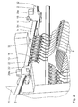
- An in Fig. 1 as a whole with 1 designated high-bay warehouse includes several storage rods 2.
- the bearing rods 2 are arranged in groups of four in two floors on both sides symmetrically to a stacker crane 3. This means that the storage and retrieval unit 3 is arranged between each two oppositely arranged bearing rods 2 of the high-bay warehouse 1.
- the bearing rods 2 are each inclined relative to a horizontal plane, wherein the inclination is directed to the stacker crane 3 out.
- the inclination is for example 10 °.
- each storage bar 2 has a locking unit 4. Goods 5 can be stored on the bearing rods 2, in particular in the form of clothing arranged on hangers.
- product 5 can automatically slip or slide in the region of the locking unit 4 toward an end facing the storage and retrieval unit 3. In this position adjacent to the locking unit 4, the goods 5 can be removed from the stacker crane 3.
- the displacement of the product 5 on the bearing rod 2 to the locking unit 4 can be carried out additionally or alternatively to the inclination by a drive.
- the high-bay warehouse 1 further comprises a storage section 6 and a removal line 7.
- About the storage section 6 goods 5 can be moved to the stacker crane 3 for storage on storage rods 2 in the high-bay warehouse 1.
- the storage section 6 may have a storage drive, not shown.
- the Einlagerumble 6 is inclined relative to the horizontal to the stacker crane 3 out. According to the embodiment shown in FIG Fig. 1 the storage section 6 is horizontal, ie without inclination, arranged.
- the Auslagerrange 7 may have to outsource the goods 5 an outrigger drive, not shown, to move the goods 5 away from the stacker crane 3 along the Auslagerrange 7 to the left. Additionally or alternatively, the Auslagerrange 7 may be inclined relative to the horizontal in order to allow an automatic transport of the goods 5 of the stacker crane 3 away. According to the embodiment shown in FIG Fig. 1 the Auslagerhold 7 is horizontal, so not inclined, arranged.
- the storage and retrieval unit 3 comprises a base unit with a not shown in detail car, which has a carriage drive, not shown.
- the carriage is a carriage, not shown, which allows a linear guide movement of the stacker crane 3 along a guide direction 9.
- the carriage is guided guided on guide rails 10 along the guide direction 9.
- the guide rails 10 are not linear and in particular represent an at least partially curved guide 9 direction.
- the guide rails 10 are firmly anchored on or in the bottom 8. It is possible that the anchoring is detachable, so that by means of the guide rails 10, the guide direction 9 can be set changeable.
- a vertical column 11 On the carriage, not shown, a vertical column 11 is fixed, which moves along with the carriage along the guide direction 9.
- a non-illustrated lifting drive is provided, which allows a lifting movement along a vertical direction 12.
- the lifting drive allows raising and lowering along the vertical direction 12.
- a horizontally arranged support arm 13 With the lifting drive a horizontally arranged support arm 13 is connected, which carries a loading / unloading rod 14.
- the loading / unloading bar 14 is oriented horizontally with its rod longitudinal axis.
- the loading / unloading bar 14 is fixed in a central region on the support arm 13 and oriented perpendicular to the support arm 13.
- more than one loading / unloading rod 14 may be present.
- the loading / unloading bar 14 has two free ends 15 which can be arranged in pairs with opposite bearing bars 2 in a transfer arrangement of the loading / unloading bar 14 such that the loading / unloading bar 14 and the storage bars 2 arranged adjacent thereto share a common transfer path for loading the high-bay warehouse 1 with goods 5 and for removing goods 5 are arranged from the high-bay warehouse 1.
- the loading / unloading bar 14 is provided with a pair of opposite bearing bars 2 in the transfer arrangement, which are arranged in the lower tier as a second pair adjacent to the storage path 6 and the storage path 7 along the guide direction 9.
- This means that the common transfer path is effected by a relative displacement of the loading / unloading bar 14 and at least one storage bar 2.
- the relative displacement is effected by an active displacement of the stacker crane 3 on the floor 8, in particular along the guide direction 9, and the loading / unloading bar 14 along the vertical direction 12.
- the bearing bar 2 remains stationary.
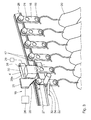
- a separating unit 16 is provided in each case.
- the singling unit 16 is used for isolated removal of the product 5 from the high-bay warehouse 1.
- the singling unit 16 cooperates with the locking unit 4 of the storage rods 2 for the isolated removal of the goods 5 together.
- the loading / unloading rod 14 is designed essentially as a downwardly open, U-shaped profile tube. At the bottom arranged opening of the U undercut webs are provided which allow a rolling or sliding of rolling / sliding bodies 17 of an adapter 18 along the rod longitudinal axis of the loading / unloading rod 14.
- the adapters 18 are on the bearing rods 2, the loading / unloading rod 14, the storage section 6 and the Auslagerumble 7 each guided displaced.
- Each adapter 18 also has a receiving opening 19, in which the individual goods 5 are suspended by means of a hanger 20 and thus attached to the adapter 18.
- the adapter 18 allows uncomplicated handling of the goods 5 and the clothes hanger 20 carrying the goods 5.
- the adapter 18 also has a transponder chip 21.
- the transponder chip 21 carries information regarding the product 5 stored on the adapter 18. For example, the nature of the product, in particular the type of garment, the manufacturer, the color of the garment, the size, the material and other properties are stored on the transponder chip 21.
- the transponder chip 21 is in particular overwritable, so that the transponder chip 21 can be used several times.
- the storage and retrieval unit 3 has a recognition unit for the automatic recognition of the removed product 5.
- the recognition unit is designed as a transponder reader 22.
- the transponder reader 22 is arranged at the free end 15 of the loading / unloading bar 14 such that, when the loading / unloading bar 14 and the storage bar 2 are in the transfer arrangement, the transponder reader 22 enables reading of a transponder chip 21 of the adapter 18, which faces the loading / unloading bar 14.
- detection of the removed product 5 can also take place in another form, for example via an identification means in the form of a barcode laser or via an optical detection of a color coding of the product 5.
- a first loading drive 23 and a second loading drive 24 are provided.
- the loading drives 23, 24 each have an actuating element which can be brought into engagement with the adapters 18.
- the adjusting elements are displaceable along the rod longitudinal axis of the loading / unloading rod 14 and drivable by means of a drive, not shown.
- the loading drives 23, 24 the goods 5 stored on the adapters 18 can be pushed onto one of the bearing rods 2 and thus the high-bay warehouse 1 can be loaded.
- the loading / unloading bar 14 it is necessary for the loading / unloading bar 14 to be arranged in the transfer arrangement, that is to say adjacent to a corresponding storage bar 2.
- the arrangement shown serves the first loading drive 23 for loading the bearing rod 2 shown on the right, wherein the second loading drive 24 is used to load the bearing rod 2 shown on the left.
- the two loading drives 23, 24 are in particular firmly coupled together, for example via a belt or chain drive.
- the first loading drive 23 according to Fig. 2 is shifted to the right along a first loading direction 33, the second loading drive 24 is simultaneously displaced along the same direction.
- the second loading drive 24 reaches a free end 15 of the loading / unloading bar 14, it is guided on a deflection roller to a rear side of the loading / unloading bar 14 facing the vertical column 11.
- the separating unit 16 comprises a separating element 25 which can be displaced along the vertical direction 12 and which by means of a pneumatic actuator 26, which in FIG Fig. 3 is shown schematically, is vertically displaceable.
- the loading / unloading rod 14 has a rod longitudinal axis 27.
- the bearing rod 2 has a rod longitudinal axis 28.
- a cutting angle a between the longitudinal axes 27, 28, ie a deviation of the loading / unloading rod 14 of a completely straight course, according to the embodiment shown about 175 °.
- the loading / unloading bar 14 is therefore bent by a small angle, which in the example illustrated is 5 °, but can also be in the range of 3 °, for example.
- the cutting angle ⁇ is in particular designed such that a displacement of the goods 5 from the loading / unloading bar 14 to a storage bar or from a storage bar 2 to the loading / unloading bar 14 is not impaired.
- the locking unit 4 of the bearing rod 2 has an actuatable, in particular by means of a in Fig. 3 schematically illustrated pneumatic actuator 29 operable claw member 30 on.
- the jaw member 30 is disposed laterally offset relative to the bearing rod 2 along the longitudinal axis 28.
- the actuator 29 By means of the actuator 29, the jaw member 30 about a vertical pivot axis 31 relative to the bearing rod 2 is pivotable.
- the jaw member 30 is arranged such that an integrally formed on the jaw member 30 claw 32 engages behind an adapter 18 such that a displacement of the adapter 18 along the longitudinal axis 28 for removing the product 5 is blocked from the bearing rod 2.
- the actuation of the jaw member 30, which is also referred to as a pawl, is spring-loaded. This means that as soon as an actuation force exerted by the actuator 29 on the jaw member 30 fails, the jaw member 30 automatically in the locking arrangement according to Fig. 3 is relocated. This can for example be done by a not shown torsion spring along the pivot axis 31 is arranged.
- the actuator for actuating the jaw member 30 can also be arranged on the opposite side of the loading / unloading rod 14 and mounted on the separating unit 16, as indicated in the drawing at 29a.
- product 5 is provided to adapters 18 via the storage path 6 of the high-bay warehouse 1.
- the storage and retrieval unit 3 is arranged in a transfer arrangement with respect to the storage section 6.
- the carriage and the vertical column 11 arranged thereon are displaced along the guide direction 9 to the storage path 6.
- the load / unload bar 14 is brought to a vertical level with the storage section 6 by means of the lifting drive.
- the product 5 is displaced from the storage path 6 to the loading / unloading rod 14.
- the storage and retrieval unit 3 is connected to a not shown, in particular centrally arranged, control unit of the high-bay warehouse 1 in signal connection.
- a target position for the goods 5 to be stored is transmitted to the storage and retrieval unit 3 via the control unit.
- a target position, ie a storage bar 2, on which the goods 5 is to be stored automatically approached by the storage and retrieval unit 3 by the carriage along the guide direction 9 and the loading / unloading rod 14 by means of the lifting drive on the support arm 13 along the vertical direction 12th be moved to the appropriate target position.
- the movement sequence that is, the displacement along the guide direction 9 and along the vertical direction 12, can be sequential, ie successively, or synchronously, ie simultaneously.
- the first loading direction 33 is oriented parallel to the rod longitudinal axis 14.
- the adapter 18 on the claw 32 of the jaw member 30 In order to allow loading of the bearing rod 2, so to allow a sliding of the adapter 18 of the loading / unloading rod 14 on the bearing rod 2, it is necessary that the adapter 18 on the claw 32 of the jaw member 30 over on the bearing rod. 2 be moved.
- the claw 32 has an insertion bevel 34.
- the insertion bevel 34 allows the claw 32 to be pushed away transversely to the loading direction 33, so that the jaw element 30 is pivoted about the pivot axis 31.
- the jaw member 30 automatically pivots back to the locking position due to the spring loaded bearing.
- the jaw member 30 is actively unlocked by means of the actuator 29 and pivoted away about the pivot axis 31 of the bearing 2 to facilitate loading of the bearing rod 2.
- the loading process is completed in particular when the first loading drive 23 occupies a defined end position on the loading / unloading rod 14, which is detected in particular by means of a limit switch, not shown, and supplied to the control unit.
- the storage and retrieval unit 3 allows a fast, direct and uncomplicated loading of several, in particular identical goods 5 on a storage bar. 2
- the loading / unloading bar 14 of the stacker crane 3 is controlled via the control unit and moved to a desired target position for removal of a target goods 5.
- a current stock is stored in the control unit.
- the control unit which type of goods 5 at what position, d. H. on which storage bar 2, is stored in the high-bay warehouse 1.
- the information of the transponder chip 21 is read on the adapter 18 of the goods to be taken 5 by means of the transponder laser 22. In the event that a different information is detected, a misappropriation can be prevented.
- This transponder function can also be omitted in a simpler version of the storage and retrieval unit 3.
- FIG. 3 Such an arrangement is in Fig. 3 shown.
- the separating unit 16 which is arranged on the storage and retrieval unit 3, with the locking unit 4, which is arranged on the respective bearing rod 2, cooperates such that unlocking and opening of the locking unit 4 is possible.
- the singulation unit 16 and the locking unit 4 are in signal connection with the control unit.
- the separating unit 16 actuates a limit switch, not shown, which transmits an unlocking signal to the locking unit 4 via the control unit.
- the unlocking signal causes unlocking of the locking unit 4th
- the locking unit 4 is unlocked by an unlocking in the form of the actuator 29 and opened by the claw member 30 is pivoted about the pivot axis 31 of the bearing rod 2.
- the opened, unlocked arrangement of the locking element 4 is in Fig. 4 shown.
- the loading / removal bar 14 facing adapter 18 is not held. Due to the inclined arrangement of the bearing rod 2, the adapter 18 rolls or slides automatically from the bearing rod 2 on the loading / unloading rod 14.
- the bearing rod 2 may have a drive.
- the separating element 25 is displaced downwards along the vertical direction 12 in order to remove the in Fig. 3 second left-side adapters 18 to prevent.
- the separating element 25 has a separating slope 35 facing the adapter 18 to be removed.
- the Separation bevel 35 is particularly designed so that when stopping the second adapter 18 at the same time the first adapter 18 is subjected to a transverse force to support a displacement along the rod longitudinal axis 27.
- the adapter 18 is pushed by the bearing rod 2 on the loading / unloading rod 14.
- the opening of the locking unit 4, the in Fig. 4 is shown, and the lowering of the separating element 25, which in Fig. 5 is typically synchronized and substantially simultaneous.
- the representation of the method steps of opening the locking unit and the lowering of the separating element 25 in the Fig. 4 and 5 essentially serves the better understanding.
- the drives for the separating element 25 and the jaw element 30 can be mechanically coupled to each other, in particular via spring biases.
- An interaction of the separating element 25 and the claw member 30 in the promotion of isolated adapter 18 can be done in the manner of a ballpoint pen mechanism.
- a maximum time offset between the opening of the locking unit 4 and the operation of the singulation unit 16 is small.
- the first step is to approach a target position with the storage and retrieval unit 3, before subsequently the occasional removal at this other storage rod is repeated.
- the product 5 is then outsourced on the Auslagerrange 7.
- the shelf storage is designed as a one-tier rack warehouse.
- the one-tier rack storage is substantially identical to the high-bay warehouse 1, wherein the storage rods are arranged only in one floor to each other. These storage bars form a storage rack floor.
- the storage and retrieval unit it is not necessary for the storage and retrieval unit to have a lifting drive in this case.
- the storage and retrieval unit is simplified.
- the storage capacity in a storage rack floor of the high-bay warehouse is identical to that of the single-storey warehouse.
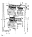
- Fig. 7 and 8th show a further embodiment of a racking 36.
- the shelf storage 36 is designed in the form of a traveling shelf warehouse. Such a bearing is also referred to as a carousel bearing. This means that the bearing rods 2, which at the in Fig. 7 three traveling rack storage 36 shown in three storage rod levels are arranged vertically spaced from each other, along a traveling shelf displacement path 37 displaced are.
- the traveling shelf displacement track 37 is a closed track and allows a circumferential displacement of the bearing rods 2 at the traveling shelf warehouse.
- the traveling rack displacement path 37 allows an endless displacement of the bearing bars 2.
- the traveling rack displacement path 37 according to the embodiment shown comprises two parallel oriented longitudinal sections and two semicircular, the two longitudinal sections interconnecting arc sections.
- the traveling shelf displacement path 37 is designed to be elongated, ie the respective length of the longitudinal sections is greater than a vertical distance of the longitudinal sections to each other.
- the length of the longitudinal sections is twice as large and in particular three times as large as the vertical distance. It is also conceivable that the traveling shelf displacement track has a different contour and in particular is substantially circular, rectangular or in another form.
- the traveling shelf storage 36 comprises a plurality of movable traveling shelf individual elements 38 that can be displaced along the traveling shelf transfer path 37.
- the traveling shelf individual elements 38 are each pivotally connected to each other with respect to a vertical axis 42. This makes it possible that the Wanderregaleinzelemia 38 along the curved arc sections of the traveling shelf displacement path 37 are displaced.
- the Wanderregaleinzelium 38 are made even.
- the bearing rods 2 extend in the radial direction relative to the Wanderregalverlagerungsbahn 37 to the outside.
- the Wanderregaleinzelemia 38 are guided guided between an upper and a lower rail.
- each traveling rack storage 36 has a traveling rack drive 39.
- a stationary storage and retrieval unit 40 is provided.
- the storage and retrieval unit 40 is designed substantially analogously to the storage and retrieval unit 3 according to the first embodiment. Due to the fact that the storage and retrieval unit 40 is arranged stationarily on the floor 8, a drive on the basic unit can be dispensed with.
- the storage and retrieval device 40 is arranged with respect to a corresponding traveling rack storage 36, that the loading / unloading bar 14 is arranged parallel to the longitudinal sections of the traveling shelf displacement path 37.
- the loading / unloading bar 14 of the storage and retrieval device 40 and a storage bar 2 of the traveling shelf storage 36 then form a common transfer distance when the storage bar 2 is arranged in an outer position along the traveling shelf displacement path 37.
- Such an arrangement is in Fig. 7 and 8th shown.
- This arrangement is particularly characterized in that the bearing rod 2 is arranged centrally between the two longitudinal sections in the region of the curved portion of the traveling shelf displacement path 37.
- the common transfer path is formed by disposing a support rod 2 along the traveling shelf transfer path 37 in the aforementioned manner and at the same time the loading / unloading rod 14 in a vertical position corresponding to the respective support rod 2. This means that, in order to obtain the common transfer distance, a required relative movement between the storage bar 2 and the loading / unloading bar 14 takes place through a displacement of the storage bar 2 along the traveling rack relocation path 37 and / or the loading / unloading bar 14 along the vertical direction 12.
- each have a storage section 6 is provided. It is also possible that only one storage section 6 is provided for several traveling rack storage 36, which is displaceable along a transverse direction 41 in order to reach the individual storage and retrieval units 40.
- the Einlagerfflen 6 are each arranged at a height level of the lowest Lagerstangenetage.
- the storage section 6 can be displaced, for example, along a guided movement, in particular by means of rails anchored on or in the ground, along the transverse direction 41.
- the storage section 6 also serves as Auslagerrange. This means that goods that have been isolated by means of the storage and retrieval unit from the traveling rack storage 36, via the loading / unloading bar 14 for unloading on the Auslagerrange that corresponds to the storage section 6, is passed. Finally, an outsourcing of the goods assembled in this way takes place via the outsourcing line.
- the functionality and in particular a method for isolated removal of goods from the traveling rack storage 36 is substantially identical to the method for removing the goods from a high-bay warehouse according to the first embodiment, to which reference is hereby made.
- the essential difference is that for arranging the stacker crane 40 on the bearing rod 2 to form a common transport path, a combined displacement takes place.
- a bearing rod 2 can be seen from the goods 5, moved to a target position such that the bearing rod 2 facing the storage and retrieval unit 40 is disposed adjacent.
- a height adjustment of the loading / unloading bar 14 takes place in order to form the transport path with the storage bar 2 from the desired storage rack floor.
- this picked goods can be removed via the storage yard 6.
- the loading / unloading bar 14 is brought into a lower vertical position, so that the loading / unloading bar 14 forms a common transport path with the storage path 6.
- a traveling shelf warehouse has exactly one Lagerstangenetage.
- a height adjustment of the stacker crane 40 can be omitted.
- the execution of the stacker crane is then simplified.
Abstract
Description
Die Erfindung betrifft ein Regalbediengerät für ein Regallager, ein Regallager mit einem derartigen Regalbediengerät und ein Verfahren zum vereinzelten Entnehmen von Ware aus einem derartigen Regallager.The invention relates to a storage and retrieval unit for a shelf storage, a shelf storage with such a stacker crane and a method for occasional removal of goods from such a shelf storage.
Ein Regalbediengerät ist aus der
Aus der
Aus der
Es ist eine Aufgabe der vorliegenden Erfindung, ein Regalbediengerät für ein Regallager derart zu gestalten, dass das Entnehmen von Ware aus dem Regallager vereinfacht und insbesondere das vereinzelte Entnehmen von Ware aus dem Regallager ermöglicht ist.It is an object of the present invention to design a storage and retrieval unit for a rack storage in such a way that the removal of goods from the shelf storage simplifies and in particular the occasional removal of goods from the shelf storage is possible.
Diese Aufgabe ist erfindungsgemäß gelöst durch ein Regalbediengerät mit den im Anspruch 1 angegebenen Merkmalen.This object is achieved by a stacker crane with the features specified in claim 1.
Erfindungsgemäß wurde erkannt, dass ein Regalbediengerät eine Vereinzelungseinheit für ein vereinzeltes Entnehmen von Ware aus einem Regallager, insbesondere einem Hochregallager, aufweist. Die Vereinzelungseinheit ist insbesondere eine aktive, insbesondere mittels eines Antriebs antreibbare, Komponente. Die aktive Vereinzelungseinheit kann insbesondere mit einer passiv ausgeführten Komponente, insbesondere einer Verriegelungseinheit, die insbesondere an einer Lagerstange eines Hochregallagers angeordnet ist, zum vereinzelten Entnehmen von Ware aus dem Regallager zusammenwirken. Das bedeutet, dass zum vereinzelten Entnehmen der Ware, insbesondere genau, eine Vereinzelungseinheit erforderlich ist. Insbesondere ist es nicht erforderlich, dass an jeder Lagerstange eine aktive Vereinzelungseinheit vorgesehen ist. Der apparative Aufwand für das Regalbediengerät und das Regallager ist dadurch reduziert. Insbesondere wird das Zusammenwirken zwischen der aktiven Vereinzelungseinheit des Regalbediengeräts mit der Verriegelungseinheit an einer Lagerstange durch eine Entriegelungseinheit ermöglicht, die insbesondere an einer Belade-/Entnahmestange des Regalbediengeräts vorgesehen ist. Dadurch ist es möglich, dass mit dem Regalbediengerät einzelne Waren, insbesondere Kleidungsstücke, vereinzelt und gezielt aus dem Regallager entnommen werden können. Insbesondere ist es denkbar, dass in einem Entnahmevorgang einzelne Waren verschiedener Lagerstangen des Regallagers entnommen und auf einer Belade-/Entnahmestange des Regalbediengeräts aufgenommen werden. Zum Beladen des Regallagers weist die Belade-/Entnahmestange einen Beladeantrieb auf. Insbesondere kann damit Ware auf eine Lagerstange des Regallagers aufgeschoben werden. Das Regalbediengerät umfasst ein Grundgerät. Das Regalbediengerät kann mit dem Grundgerät insbesondere auf dem Boden angeordnet und entlang des Bodens verlagerbar ausgeführt sein. Es ist alternativ auch möglich, dass das Grundgerät beispielsweise an einem oberhalb des Regallagers angeordneten Führungssystem hängend angeordnet verlagerbar ist. Das Grundgerät kann einen Wagen mit einem Wagenantrieb zum Bewegen des Wagens auf dem Boden aufweisen. Insbesondere ermöglicht der Wagen ein Bewegen in der Ebene. Weiterhin kann das Grundgerät einen Hubantrieb umfassen. Der Hubantrieb ermöglicht ein Verlagern der Belade-/Entnahmestange in einer Richtung quer zum Boden. Insbesondere ist der Hubantrieb längs einer Vertikalsäule geführt. Die Vertikalsäule ist insbesondere fest mit dem Wagen und insbesondere senkrecht zu einer von dem Wagen gebildeten Wagenebene orientiert. Das Regelbediengerät ist zum vereinzelten Entnehmen von Ware aus einem Regallager verschiedener Typen geeignet. Das Regalbediengerät ermöglicht ein vereinzeltes Entnehmen von Ware beispielsweise aus einem Hochregallager, aus einem einetagigen Regallager sowie aus einem Wanderregallager, bei welchem die Lagerstangen verlagerbar sind.According to the invention, it has been recognized that a storage and retrieval unit has a separating unit for occasional removal of goods from a shelf storage, in particular a high-bay warehouse. The singling unit is in particular an active, in particular drivable by means of a drive, component. The active separation unit can interact in particular with a passively executed component, in particular a locking unit, which is arranged in particular on a storage rod of a high-bay warehouse, for occasional removal of goods from the shelf storage. This means that for the isolated removal of the goods, in particular exactly, a separation unit is required. In particular, it is not necessary that at each storage bar a active separation unit is provided. The equipment required for the storage and retrieval unit and the shelf storage is reduced. In particular, the interaction between the active separation unit of the storage and retrieval unit with the locking unit on a storage rod is made possible by an unlocking unit, which is provided in particular on a loading / unloading rod of the storage and retrieval unit. This makes it possible that with the storage and retrieval unit individual goods, especially garments, isolated and can be selectively removed from the shelf storage. In particular, it is conceivable that taken in a removal process individual goods different storage rods of the shelf storage and recorded on a loading / unloading bar of the storage and retrieval device. For loading the shelf storage, the loading / unloading bar has a loading drive. In particular, goods can thus be pushed onto a storage bar of the shelf storage. The storage and retrieval unit comprises a basic unit. The storage and retrieval unit can be arranged with the base unit, in particular on the floor and be designed to be displaceable along the floor. It is alternatively also possible that the basic unit is arranged to be displaceable, for example, arranged suspended on a guide system arranged above the shelf storage. The base unit may have a carriage with a carriage drive for moving the carriage on the ground. In particular, the carriage allows for moving in the plane. Furthermore, the basic unit may comprise a lifting drive. The lifting drive allows a displacement of the loading / unloading bar in a direction transverse to the ground. In particular, the lifting drive is guided along a vertical column. The vertical column is particularly oriented with the car and in particular perpendicular to a car plane formed by the car. The control panel is suitable for the occasional removal of goods from a rack warehouse of various types. The storage and retrieval unit allows individual removal of goods for example, from a high-bay warehouse, a one-tier rack warehouse and a traveling shelf warehouse, in which the storage rods are displaced.
Ein Regalbediengerät mit einer Steuerungseinheit nach Anspruch 2 ermöglicht ein automatisiertes und insbesondere vollautomatisches Entnehmen von Ware aus dem Regallager. Insbesondere ist es möglich, eine vorkommissionierte Warenauswahl, also eine bestimmte Kombination einzelner Waren, die insbesondere auf verschiedenen Lagerstangen des Regallagers angeordnet sind, zusammenzustellen und mittels des Regalbediengeräts aus dem Regallager zu entnehmen. Die Steuerungseinheit kann auch ein Beladen des Regallagers ermöglichen.A storage and retrieval unit with a control unit according to
Ein Regalbediengerät nach Anspruch 3 ermöglicht eine Überwachung des Entnahmevorgangs. Insbesondere kann dadurch ausgeschlossen werden, dass Waren in einer nicht gewünschten Menge, also in zu großer oder zu geringer Stückzahl, entnommen werden. Die Erkennungseinheit kann zum Identifizieren der entnommenen Ware ausgebildet sein. Insbesondere ist die Erkennungseinheit ein Transponderleser. Hierzu kann die Erkennungseinheit als Barcodelaser ausgestaltet sein. Auch eine Farbcodierung zur Identifikation der Ware kann genutzt werden, die von der Erkennungseinheit optisch erfasst werden kann.A storage and retrieval unit according to
Ein Regalbediengerät nach Anspruch 4 ermöglicht eine direkte und unkomplizierte Erkennung der entnommenen Ware. Durch die Verwendung eines Transponderlesers als Erkennungseinheit kann Zusatzinformation bei der Entnahme von einem Transponder ausgelesen werden. Beispielsweise ist es denkbar, dass der Transponder Informationen wie beispielsweise die Art der Ware, eine Artikelnummer, ein Einlagerungsdatum, Größe, Farbe und Designer eines Kleidungsstücks trägt. Ein Taster oder eine Lichtschranke ermöglichen eine besonders kostengünstige Erkennung des Entnahmevorgangs.A storage and retrieval unit according to
Ein Regalbediengerät mit einer Vereinzelungseinheit nach Anspruch 5 ermöglicht ein direktes Eingreifen in den Entnahmevorgang. Die Vereinzelungseinheit ermöglicht ein mechanisch gestütztes Entnehmen der gewünschten Ware.A storage and retrieval unit with a separating unit according to
Ein Regalbediengerät nach Anspruch 6 vereinfacht die Handhabung der Ware. Insbesondere ist eine Handhabung mit dem Regalbediengerät und dem Regallager unabhängig von der Ware selbst möglich. Dadurch ist es möglich, voneinander verschiedene Waren vereinzelt in einfacher Weise zu handhaben. Die Verwendung eines Adapters ermöglicht eine definierte Schnittstelle für das Regalbediengerät und das Regallager hinsichtlich der Lagerung und Handhabung der Waren.A stacker crane according to
Es ist eine weitere Aufgabe der vorliegenden Erfindung, ein Regallager derart zu schaffen, dass das Entnehmen von Ware vereinfacht und insbesondere das vereinzelte Entnehmen von Ware ermöglicht ist.It is a further object of the present invention to provide a rack storage in such a way that the removal of goods is simplified and in particular the occasional removal of goods is possible.
Diese Aufgabe ist erfindungsgemäß gelöst durch ein Regallager mit den im Anspruch 7 angegebenen Merkmalen.This object is achieved by a rack warehouse with the features specified in
Erfindungsgemäß wurde erkannt, dass ein Regallager mindestens eine Lagerstange zum Lagern von Ware aufweist, wobei ein Regalbediengerät mit der Belade-/Entnahmestange benachbart zu der mindestens einen Lagerstange unter Bildung einer gemeinsamen Transferstrecke anordenbar ist. Die Belade-/Entnahmestange und die Lagerstange sind entlang deren Stangenlängsachsen hintereinander angeordnet. Es ist möglich, dass die Stangenlängsachsen, die jeweils insbesondere linear ausgeführt sind, im Bereich des Übergangs zwischen der Lagerstange und der Belade-/Entnahmestange einen leichten Knick, also eine geringfügige Abweichung von einen geraden Verlauf der Stange im Bereich des Übergangs, aufweisen. Ein derartiger Knick weist einen Winkel von mindestens 170°, insbesondere mindestens 175° und insbesondere mindestens 177° auf. Die gemeinsame Transferstrecke dient zum Beladen des Regallagers mit Ware und zum Entnehmen von Ware aus dem Regallager.According to the invention, it has been recognized that a rack store has at least one storage bar for storing goods, wherein a stacker crane with the loading / unloading bar adjacent to the at least one storage bar can be arranged to form a common transfer line. The loading / unloading bar and the storage bar are along their longitudinal bars arranged one behind the other. It is possible that the rod longitudinal axes, which are each designed in particular linear, in the region of the transition between the bearing rod and the loading / unloading rod a slight kink, so a slight deviation from a straight course of the rod in the transition area have. Such a kink has an angle of at least 170 °, in particular at least 175 ° and in particular at least 177 °. The common transfer line is used to load the shelf warehouse with goods and to remove goods from the shelf storage.
Ein Regallager nach Anspruch 8 ermöglicht ein sicheres Lagern der Ware an der mindestens einen Lagerstange. Insbesondere für den Fall, dass die Lagerstange gegenüber einer Horizontalen geneigt ist, um ein automatisches, schwerkraftbedingtes Fördern von Ware entlang der Stangenlängsachse zu ermöglichen, dient eine Verriegelungseinheit zum sicheren Verriegeln der Ware an der Lagerstange. Ein unbeabsichtigtes Entnehmen der Ware ist ausgeschlossen.A shelf storage according to
Bei einem Regallager nach Anspruch 9 ist an der Belade-/Entnahmestange des Regalbediengeräts eine Entriegelungseinheit vorgesehen. Die Entriegelungseinheit korrespondiert mit der Verriegelungseinheit der mindestens einen Lagerstange. Die Entriegelungseinheit dient zum Entriegeln der Verriegelungseinheit. Die Entriegelungseinheit ermöglicht insbesondere ein automatisches Entriegeln der Verriegelungseinheit, wenn die Belade-/Entnahmestange in einer Transferanordnung angeordnet ist, also sich benachbart zu der mindestens einen Lagerstange unter Bildung der gemeinsamen Transferstrecke befindet.In a rack warehouse according to
Ein Regallager gemäß Anspruch 10 ermöglicht ein schnelles und direktes Einlagern und Auslagern von Ware mittels des Regalbediengeräts. Eine Einlagerstrecke und eine Auslagerstrecke sind insbesondere derart angeordnet, dass sie mit der Belade-/Entnahmestange des Regalbediengeräts in eine Transferanordnung bringbar sind. Dadurch ist es möglich, Ware schnell und unkompliziert auf die Belade-/Entnahmestange zu verlagern und von der Belade-/Entnahmestange wieder zu entnehmen.A rack warehouse according to
Ein Regallager nach Anspruch 11 ermöglicht eine effektive Nutzung des Regallagers mit einem einzigen Regalbediengerät. Die Lagerkapazität ist hoch. Es ist möglich, viel Ware mit einer hohen Dichte, d. h. mit geringem Platzbedarf, in dem Regallager einzulagern. Die Lagerhaltungskosten sind reduziert. Ein derartiges Lager mit hoher Lagerkapazität ist beispielsweise ein Hochregallager. In einem Hochregallager sind mehrere Lagerstangen horizontal beabstandet zueinander angeordnet. Diese Lagerstangen bilden eine Lageretage. In einem Hochregallager sind mehrere und insbesondere mindestens drei Lageretagen über einander, d. h. vertikal beabstandet zueinander, angeordnet. In einem Hochregallager sind die Lagerstangen ortsfest angeordnet. Es ist möglich, dass die Lagerstangen eines Hochregallagers mit Stirnseiten beabstandet und einander zugewandt angeordnet sind. Die Lagerstangen eines derartigen Hochregallagers bilden eine Lagergasse, in der das Regalbediengerät angeordnet ist. Ebenfalls eine hohe Lagerkapazität weist ein Wanderregallager auf. In einem Wanderregallager sind mehrere Lagerstangen in einer Lagerstangenebene angeordnet. Ein Wanderregallager kann mehrere Lagerstangenebenen umfassen. Ein Wanderregallager ermöglicht eine Verlagerung der Lagerstangen entlang einer Wanderregalverlagerungsbahn. Die Lagerstangen sind verlagerbar und insbesondere nicht ortsfest.A rack warehouse according to
Es ist eine weitere Aufgabe der vorliegenden Erfindung, ein Verfahren zum vereinzelten Entnehmen von Ware aus einem Regallager bereitzustellen.It is a further object of the present invention to provide a method for the occasional removal of goods from a shelf storage.
Diese Aufgabe ist erfindungsgemäß gelöst durch ein Verfahren mit den im Anspruch 12 angegebenen Merkmalen.This object is achieved by a method having the features specified in
Erfindungsgemäß wurde erkannt, dass durch das Bereitstellen eines Regallagers gemäß der vorliegenden Erfindung und entsprechenden Regalbediengerät Ware vereinzelt aus dem Regallager entnehmbar ist. Die Vorteile des Verfahrens entsprechen im Wesentlichen den Vorteilen des Regalbediengeräts und des Regallagers, worauf hiermit verwiesen wird.According to the invention, it has been recognized that the provision of a shelf storage according to the present invention and the corresponding storage and retrieval unit can be used to remove individual goods from the shelf storage. The advantages of the method essentially correspond to the advantages of the storage and retrieval unit and the rack storage, to which reference is hereby made.
Ausführungsbeispiele der Erfindung werden nachfolgend anhand der Zeichnung näher erläutert. In dieser zeigen:
- Fig. 1
- eine perspektivische Darstellung eines Hochregallagers mit einem Regalbediengerät gemäß einer ersten Ausführungsform;
- Fig. 2
- eine perspektivische, vergrößerte Darstellung des Regalbediengeräts gemäß
Fig. 1 mit daran angeordneten Waren; - Fig. 3
- eine perspektivische, vergrößerte Darstellung eines vereinzelten Entnehmens von Ware mit dem Regalbediengerät gemäß
Fig. 1 mit einer Verriegelungseinheit in einer Verriegelungsposition; - Fig. 4
- eine
Fig. 3 entsprechende Darstellung mit der Verriegelungseinheit in einer Entriegelungsposition; - Fig. 5
- eine
Fig. 4 entsprechende Darstellung mit einer Vereinzelungseinheit in einer Eingriffsposition; - Fig. 6
- eine
Fig. 5 entsprechende Darstellung mit der Verriegelungseinheit in der Verriegelungsposition und der Vereinzelungseinheit in einer Nicht-Eingriffsposition; - Fig.7
- eine perspektivische Darstellung einer Anordnung von drei Wanderregallagern mit jeweils einem Regalbediengerät gemäß einer weiteren Ausführungsform der Erfindung und
- Fig. 8
- eine perspektivische, vergrößerte Darstellung des Regalbediengeräts gemäß
Fig. 7 mit daran angeordneten Waren.
- Fig. 1
- a perspective view of a high-bay warehouse with a stacker crane according to a first embodiment;
- Fig. 2
- a perspective, enlarged view of the storage and retrieval device according to
Fig. 1 with goods arranged thereon; - Fig. 3
- a perspective, enlarged view of a single removal of goods with the stacker crane according to
Fig. 1 with a locking unit in a locking position; - Fig. 4
- a
Fig. 3 corresponding representation with the locking unit in an unlocked position; - Fig. 5
- a
Fig. 4 corresponding representation with a separating unit in an engaged position; - Fig. 6
- a
Fig. 5 corresponding representation with the locking unit in the locking position and the separating unit in a disengaged position; - Figure 7
- a perspective view of an arrangement of three walking shelf storage, each with a stacker crane according to another embodiment of the invention and
- Fig. 8
- a perspective, enlarged view of the storage and retrieval device according to
Fig. 7 with goods arranged thereon.
Ein in
Das Hochregallager 1 umfasst weiterhin eine Einlagerstrecke 6 und eine Auslagerstrecke 7. Über die Einlagerstrecke 6 kann Ware 5 auf das Regalbediengerät 3 zum Einlagern auf Lagerstangen 2 im Hochregallager 1 verlagert werden. Dazu kann die Einlagerstrecke 6 einen nicht dargestellten Einlagerantrieb aufweisen. Zusätzlich oder alternativ ist es auch denkbar, dass die Einlagerstrecke 6 gegenüber der Horizontalen zu dem Regalbediengerät 3 hin geneigt ist. Gemäß dem gezeigten Ausführungsbeispiel in
Die Auslagerstrecke 7 kann zum Auslagern der Ware 5 einen nicht dargestellten Auslagerantrieb aufweisen, um die Ware 5 von dem Regalbediengerät 3 weg entlang der Auslagerstrecke 7 nach links zu verlagern. Zusätzlich oder alternativ kann die Auslagerstrecke 7 gegenüber der Horizontalen geneigt sein, um einen selbsttätigen Transport der Ware 5 von dem Regalbediengerät 3 weg zu ermöglichen. Gemäß dem gezeigten Ausführungsbeispiel in
Bei nicht dargestellten Ausführungen des Hubregallagers 1 können auch mehrere Einlagerstrecken 6 und/oder mehrere Auslagerstrecken 7 vorhanden sein.In embodiments of the Hubregallagers 1 not shown and
Im Folgenden wird das Regalbediengerät 3 anhand der
An dem nicht dargestellten Schlitten ist eine Vertikalsäule 11 befestigt, die sich zusammen mit dem Schlitten entlang der Führungsrichtung 9 bewegt. An der Vertikalsäule 11 ist ein nicht näher dargestellter Hubantrieb vorgesehen, der eine Hubbewegung entlang einer Vertikalrichtung 12 ermöglicht. Der Hubantrieb ermöglicht ein Anheben und Absenken entlang der Vertikalrichtung 12. Mit dem Hubantrieb ist ein horizontal angeordneter Trägerarm 13 verbunden, der eine Belade-/Entnahmestange 14 trägt. Die Belade-/Entnahmestange 14 ist mit ihrer Stangenlängsachse horizontal orientiert. Die Belade-/Entnahmestange 14 ist in einem mittigen Bereich an dem Trägerarm 13 befestigt und senkrecht zu dem Trägerarm 13 orientiert. Bei einer nicht dargestellten Variante des Regalbediengeräts 3 kann auch mehr als eine Belade-/Entnahmestange 14 vorhanden sein.On the carriage, not shown, a
Die Belade-/Entnahmestange 14 weist zwei freie Enden 15 auf, die paarweise mit einander gegenüberliegenden Lagerstangen 2 in einer Transferanordnung der Belade-/Entnahmestange 14 derart anordenbar sind, dass die Belade-/Entnahmestange 14 und die benachbart dazu angeordneten Lagerstangen 2 eine gemeinsame Transferstrecke zum Beladen des Hochregallagers 1 mit Ware 5 und zum Entnehmen von Ware 5 aus dem Hochregallager 1 angeordnet sind. Gemäß der Darstellung in
An den freien Enden 15 der Belade-/Entnahmestange 14 ist jeweils eine Vereinzelungseinheit 16 vorgesehen. Die Vereinzelungseinheit 16 dient zum vereinzelten Entnehmen der Ware 5 aus dem Hochregallager 1. Die Vereinzelungseinheit 16 wirkt mit der Verriegelungseinheit 4 der Lagerstangen 2 zum vereinzelten Entnehmen der Ware 5 zusammen.At the free ends 15 of the loading /
Die Belade-/Entnahmestange 14 ist im Wesentlichen als nach unten geöffnetes, U-förmiges Profilrohr ausgeführt. An der unten angeordneten Öffnung des U sind Hinterschnitt-Stege vorgesehen, die ein Abrollen oder Gleiten von Roll-/Gleitkörpern 17 eines Adapters 18 entlang der Stangenlängsachse der Belade-/Entnahmestange 14 ermöglichen. Die Adapter 18 sind an den Lagerstangen 2, der Belade-/Entnahmestange 14, der Einlagerstrecke 6 und der Auslagerstrecke 7 jeweils geführt verlagerbar. Jeder Adapter 18 weist zudem eine Aufnahmeöffnung 19 auf, in die die einzelne Ware 5 mittels eines Kleiderbügels 20 eingehängt und damit an dem Adapter 18 befestigt ist. Der Adapter 18 ermöglicht eine unkomplizierte Handhabung der Ware 5 bzw. der die Ware 5 tragenden Kleiderbügel 20. Insbesondere eine Veränderung der Bügelform führt nicht zwangsläufig zu einer Beeinträchtigung dessen Handhabung. Der Adapter 18 weist zudem einen Transponderchip 21 auf. Der Transponderchip 21 trägt Informationen bezüglich der an dem Adapter 18 gelagerten Ware 5. Beispielsweise sind auf dem Transponderchip 21 die Art der Ware, insbesondere die Art des Kleidungsstücks, des Herstellers, die Farbe des Kleidungsstücks, die Größe, das Material und andere Eigenschaften gespeichert. Der Transponderchip 21 ist insbesondere überschreibbar, so dass der Transponderchip 21 mehrfach verwendbar ist.The loading /
Gemäß dem gezeigten Ausführungsbeispiel weist das Regalbediengerät 3 eine Erkennungseinheit zum automatischen Erkennen der entnommenen Ware 5 auf. Die Erkennungseinheit ist als Transponderleser 22 ausgeführt. Der Transponderleser 22 ist an dem freien Ende 15 der Belade-/Entnahmestange 14 derart angeordnet, dass, wenn sich die Belade-/Entnahmestange 14 und die Lagerstange 2 in der Transferanordnung befinden, der Transponderleser 22 ein Auslesen eines Transponderchips 21 des Adapters 18 ermöglicht, der der Belade-/Entnahmestange 14 zugewandt ist. Anstelle des Transponderchips 21 und des Transponderlasers 22 kann ein Erkennen der entnommenen Ware 5 auch in anderer Form geschehen, beispielsweise über ein Identifikationsmittel in Form eines Barcodelasers oder über eine optische Erfassung einer Farbcodierung der Ware 5.According to the exemplary embodiment shown, the storage and
An dem Regalbediengerät 3 sind ein erster Beladeantrieb 23 und ein zweiter Beladeantrieb 24 vorgesehen. Die Beladeantriebe 23, 24 weisen jeweils ein Stellelement auf, das mit den Adaptern 18 in Eingriff bringbar ist. Die Stellelemente sind entlang der Stangenlängsachse der Belade-/Entnahmestange 14 verlagerbar und mittels eines nicht dargestellten Antriebs antreibbar. Mittels der Beladeantriebe 23, 24 kann die an den Adaptern 18 gelagerte Ware 5 auf eine der Lagerstangen 2 geschoben und somit das Hochregallager 1 beladen werden. Dazu ist es erforderlich, dass die Belade-/Entnahmestange 14 in der Transferanordnung, also benachbart zu einer entsprechenden Lagerstange 2, angeordnet ist. Gemäß der in
Die beiden Beladeantriebe 23, 24 sind insbesondere fest miteinander gekoppelt, beispielsweise über einen Riemen- oder Kettenantrieb. Wenn der erste Beladeantrieb 23 gemäß
Die Vereinzelungseinheit 16 umfasst ein entlang der Vertikalrichtung 12 verlagerbares Vereinzelungselement 25, das mittels eines pneumatischen Aktors 26, der in
Die Belade-/Entnahmestange 14 weist eine Stangenlängsachse 27 auf. Die Lagerstange 2 weist eine Stangenlängsachse 28 auf. In der in
Im Folgenden wird die Verriegelungseinheit 4 der Lagerstange 2 näher erläutert. Die Verriegelungseinheit 4 weist ein betätigbares, insbesondere mittels eines in
Im Folgenden wird ein Verfahren zum Be- und Entladen des Hochregallagers 1 im Einzelnen erläutert.In the following, a method for loading and unloading the high-bay warehouse 1 will be explained in detail.
In einem ersten Schritt wird Ware 5 an Adaptern 18 über die Einlagerstrecke 6 des Hochregallagers 1 bereitgestellt. Anschließend wird das Regalbediengerät 3 in eine Transferanordnung bezüglich der Einlagerstrecke 6 angeordnet. Dazu wird der Wagen und die darauf angeordnete Vertikalsäule 11 entlang der Führungsrichtung 9 zu der Einlagerstrecke 6 hin verlagert. Zusätzlich wird mittels des Hubantriebs die Belade-/Entnahmestange 14 auf ein Vertikalniveau mit der Einlagerstrecke 6 gebracht. Sobald die Belade-/Entnahmestange 14 sich in Transferanordnung zu der Einlagerstrecke 6 befindet, wird die Ware 5 von der Einlagerstrecke 6 auf die Belade-/Entnahmestange 14 verlagert.In a first step,
Das Regalbediengerät 3 steht mit einer nicht dargestellten, insbesondere zentral angeordneten, Steuerungseinheit des Hochregallagers 1 in Signalverbindung. Über die Steuerungseinheit wird eine Zielposition für die einzulagernde Ware 5 an das Regalbediengerät 3 übermittelt. Daraufhin wird eine Zielposition, also eine Lagerstange 2, auf die die Ware 5 einzulagern ist, von dem Regalbediengerät 3 selbsttätig angefahren, indem der Wagen entlang der Führungsrichtung 9 und die Belade-/Entnahmestange 14 mittels des Hubantriebs über den Trägerarm 13 entlang der Vertikalrichtung 12 in die entsprechende Zielposition verfahren werden. Der Bewegungsablauf, also die Verlagerung entlang der Führungsrichtung 9 und entlang der Vertikalrichtung 12, kann sequentiell, also nacheinander, oder synchron, also gleichzeitig, erfolgen.The storage and
Sobald die Belade-/Entnahmestange 14 in der Transferanordnung gemäß
Um ein Beladen der Lagerstange 2 zu ermöglichen, also um ein Aufschieben der Adapter 18 von der Belade-/Entnahmestange 14 auf die Lagerstange 2 zu ermöglichen, ist es erforderlich, dass die Adapter 18 an der Klaue 32 des Klauenelements 30 vorbei auf die Lagerstange 2 verschoben werden. Dazu weist die Klaue 32 eine Einführschräge 34 auf. Die Einführschräge 34 ermöglicht durch ein Aufschieben eines Adapters 18 entlang der ersten Beladerichtung 33, dass die Klaue 32 quer zur Beladerichtung 33 weggedrückt wird, so dass das Klauenelement 30 um die Schwenkachse 31 aufgeschwenkt wird. Sobald der Adapter 18 an dem Klauenelement 30 entlang der Beladerichtung 33 verlagert worden ist, schwenkt das Klauenelement 30 aufgrund der federbelasteten Lagerung automatisch in die Verriegelungsposition zurück.In order to allow loading of the bearing
Zusätzlich oder alternativ ist es denkbar, dass das Klauenelement 30 mittels des Aktors 29 aktiv entriegelt und um die Schwenkachse 31 von der Lagerstande 2 weggeschwenkt wird, um ein Beladen der Lagerstange 2 zu vereinfachen.Additionally or alternatively, it is conceivable that the
Der Beladevorgang ist insbesondere dann abgeschlossen, wenn der erste Beladeantrieb 23 eine definierte Endposition an der Belade-/Entnahmestange 14 einnimmt, die insbesondere mittels eines nicht dargestellten Endschalters erfasst und der Steuerungseinheit zugeführt wird. Das Regalbediengerät 3 ermöglicht ein schnelles, direktes und unkompliziertes Beladen mehrerer, insbesondere identischer Waren 5 auf eine Lagerstange 2.The loading process is completed in particular when the
Für ein Entnehmen von Ware 5 der Lagerstangen 2 des Hochregallagers 1 wird die Belade-/Entnahmestange 14 des Regalbediengeräts 3 über die Steuerungseinheit angesteuert und in eine gewünschte Zielposition zur Entnahme eine Zielware 5 verlagert. Um eine gewünschte Zielposition der Belade-/Entnahmestange 14 zu ermitteln, ist in der Steuerungseinheit ein aktueller Lagerbestand hinterlegt. Insbesondere ist in der Steuerungseinheit gespeichert, welche Art von Ware 5 an welcher Position, d. h. auf welcher Lagerstange 2, in dem Hochregallager 1 bevorratet ist.For a removal of
Bevor eine konkret zu entnehmende Ware 5 aus dem Hochregallager 1 entnommen wird, wird mittels des Transponderlasers 22 die Information des Transponderchips 21 an dem Adapter 18 der zu entnehmenden Ware 5 gelesen. Für den Fall, dass eine abweichende Information festgestellt wird, kann eine Fehlentnahme verhindert werden. Diese Transponderfunktion kann bei einer einfacheren Ausführung des Regalbediengeräts 3 auch entfallen.Before a concrete goods to be taken 5 is removed from the high-bay warehouse 1, the information of the
Eine derartige Anordnung ist in
Ausgehend von der Anordnung in
Um zu verhindern, dass unbeabsichtigt mehrere Adapter 18 von der Lagerstange 2 auf die Belade-/Entnahmestange 14 verlagert werden, dass also ein unbeabsichtigtes Entnehmen mehrerer Waren 5 erfolgt, wird das Vereinzelungselement 25 entlang der Vertikalrichtung 12 nach unten verlagert, um ein Entnehmen des in
Sobald der erste, der Belade-/Entnahmestange 14 zugewandte Adapter 18 mit der daran befestigten Ware 5 entnommen ist, also von der Lagerstange 2 auf die Belade-/Entnahmestange 14 verlagert ist, werden die Verriegelungseinheit 4 und die Vereinzelungseinheit 16 in die jeweilige Ausgangsposition zurückverlagert. Diese Anordnung ist in
In einem weiteren, nicht dargestellten Ausführungsbeispiel ist das Regallager als ein einetagiges Regallager ausgeführt. Insbesondere ist das einetagige Regallager im Wesentlichen identisch zu dem Hochregallager 1, wobei die Lagerstangen lediglich in einer Etage zueinander angeordnet sind. Diese Lagerstangen bilden eine Lagerstangenetage. Es ist insbesondere nicht erforderlich, dass das Regalbediengerät in diesem Fall einen Hubantrieb aufweist. Das Regalbediengerät ist vereinfacht. Die Lagerkapazität in einer Lagerstangenetage des Hochregallagers ist identisch zu der des einetagigen Regallagers.In a further, not shown embodiment, the shelf storage is designed as a one-tier rack warehouse. In particular, the one-tier rack storage is substantially identical to the high-bay warehouse 1, wherein the storage rods are arranged only in one floor to each other. These storage bars form a storage rack floor. In particular, it is not necessary for the storage and retrieval unit to have a lifting drive in this case. The storage and retrieval unit is simplified. The storage capacity in a storage rack floor of the high-bay warehouse is identical to that of the single-storey warehouse.
Das Regallager 36 ist in Form eines Wanderregallagers ausgeführt. Ein derartiges Lager wird auch als Karusselllager bezeichnet. Das bedeutet, dass die Lagerstangen 2, die bei den in
Das Wanderregallager 36 umfasst mehrere, entlang der Wanderregalverlagerungsbahn 37 verlagerbare Wanderregaleinzelelemente 38. Die Wanderregaleinzelelemente 38 sind jeweils bezüglich einer vertikalen Achse 42 schwenkbar miteinander verbunden. Dadurch ist es möglich, dass die Wanderregaleinzelelemente 38 entlang der gekrümmten Bogenabschnitte der Wanderregalverlagerungsbahn 37 verlagerbar sind. Die Wanderregaleinzelelemente 38 sind eben ausgeführt. Ausgehend von den Wanderregaleinzelelementen 38 erstrecken sich die Lagerstangen 2 in radialer Richtung bezogen auf die Wanderregalverlagerungsbahn 37 nach außen. Die Wanderregaleinzelelemente 38 sind zwischen einer oberen und einer unteren Schiene geführt verlagerbar. Für die Verlagerung der Wanderregaleinzelelemente 38 weist jedes Wanderregallager 36 einen Wanderregalantrieb 39 auf.The traveling
Jeweils in einem Kopfbereich des Wanderregallagers 36 ist ein ortsfestes Regalbediengerät 40 vorgesehen. Das Regalbediengerät 40 ist im Wesentlichen analog zu dem Regalbediengerät 3 gemäß der ersten Ausführungsform ausgeführt. Dadurch, dass das Regalbediengerät 40 ortsfest auf dem Boden 8 angeordnet ist, kann ein Antrieb an dem Grundgerät entfallen.Each in a head portion of the traveling
Das Regalbediengerät 40 ist derart bezüglich eines korrespondierenden Wanderregallagers 36 angeordnet, dass die Belade-/Entnahmestange 14 parallel zu den Längsabschnitten der Wanderregalverlagerungsbahn 37 angeordnet ist. Die Belade-/Entnahmestange 14 des Regalbediengeräts 40 und eine Lagerstange 2 des Wanderregallagers 36 bilden dann eine gemeinsame Transferstrecke, wenn die Lagerstange 2 in einer äußeren Position entlang der Wanderregalverlagerungsbahn 37 angeordnet ist. Eine derartige Anordnung ist in
Zum Einlagern von Ware 5 in Form von Kleidungsstücken in das Wanderregallager 36 ist jeweils eine Einlagerstrecke 6 vorgesehen. Es ist auch möglich, dass für mehrere Wanderregallager 36 nur eine Einlagerstrecke 6 vorgesehen ist, die entlang einer Querrichtung 41 verlagerbar ist, um die einzelnen Regalbediengeräte 40 zu erreichen.For storing
Die Einlagerstrecken 6 sind jeweils auf einem Höheniveau der untersten Lagerstangenetage angeordnet. Die Einlagerstrecke 6 kann beispielsweise entlang einer geführten Bewegung, insbesondere mittels am oder im Boden verankerten Schienen entlang der Querrichtung 41 verlagert werden.The
Die Einlagerstrecke 6 dient gleichzeitig als Auslagerstrecke. Das bedeutet, dass Ware, die mittels des Regalbediengeräts vereinzelt aus dem Wanderregallager 36 entnommen worden ist, über die Belade-/Entnahmestange 14 zum Entladen auf die Auslagerstrecke, die der Einlagerstrecke 6 entspricht, übergeben wird. Über die Auslagerstrecke erfolgt abschließend ein Auslagern der so zusammengestellten Ware.The
Die Funktionalität und insbesondere ein Verfahren zum vereinzelten Entnehmen von Ware aus dem Wanderregallager 36 ist im Wesentlichen identisch mit dem Verfahren zum Entnehmen der Ware aus einem Hochregallager gemäß der ersten Ausführungsform, worauf hiermit verwiesen wird. Wesentlicher Unterschied ist, dass für ein Anordnen des Regalbediengeräts 40 an der Lagerstange 2 unter Bildung einer gemeinsamen Transportstrecke eine kombinierte Verlagerung erfolgt. Einerseits wird eine Lagerstange 2, von der Ware 5 zu entnehmen ist, in eine Zielposition derart verfahren, dass die Lagerstange 2 dem Regalbediengerät 40 zugewandt und benachbart angeordnet ist. Das bedeutet also, dass das Wanderregaleinzelelement 38, an dem die Ziel-Lagerstange 2 angeordnet ist, dem Regalbediengerät 40 zugewandt ist. Für das vereinzelte Entnehmen der Zielware erfolgt eine Höhenverstellung der Belade-/Entnahmestange 14, um die Transportstrecke mit der Lagerstange 2 aus der gewünschten Lagerstangenetage zu bilden.The functionality and in particular a method for isolated removal of goods from the traveling
Sobald eine gewünschte Auswahl an Ware 5 auf der Belade-/Entnahmestange 14 angeordnet ist, kann diese kommissionierte Ware über die Einlagerstrecke 6 ausgelagert werden. Dazu wird die Belade-/Entnahmestange 14 in eine untere Vertikalposition gebracht, sodass die Belade-/Entnahmestange 14 mit der Einlagerstrecke 6 eine gemeinsame Transportstrecke bildet.As soon as a desired selection of
Es ist auch möglich, dass ein Wanderregallager genau eine Lagerstangenetage aufweist. In diesem Fall kann eine Höhenverstellung des Regalbediengeräts 40 entfallen. Die Ausführung des Regalbediengeräts ist dann vereinfacht.It is also possible that a traveling shelf warehouse has exactly one Lagerstangenetage. In this case, a height adjustment of the
Claims (15)
wobei die Belade-/Entnahmestange (14) benachbart zu der mindestens einen Lagerstange (2) unter Bildung einer gemeinsamen Transferstrecke zum Beladen des Regallagers (1) mit Ware (5) und zum vereinzelten Entnehmen von Ware (5) aus dem Regallager (1) anordenbar ist.
wherein the loading / unloading bar (14) adjacent to the at least one storage bar (2) to form a common transfer line for loading the shelf storage (1) with goods (5) and for occasional removal of goods (5) from the shelf storage (1). can be arranged.
Applications Claiming Priority (2)
| Application Number | Priority Date | Filing Date | Title |
|---|---|---|---|
| DE201210213592 DE102012213592A1 (en) | 2012-08-01 | 2012-08-01 | Storage and retrieval device for high bay warehouse, has base unit displaced on base, while loading- or removing rod is mounted on base unit, where loading actuator is arranged at loading- or removing rod for loading goods in warehouse |
| DE201210215364 DE102012215364A1 (en) | 2012-08-30 | 2012-08-30 | Storage and retrieval system for goods e.g. clothes in high-bay warehouse, has separation unit for isolated removal of goods from shelf bearing |
Publications (1)
| Publication Number | Publication Date |
|---|---|
| EP2692667A1 true EP2692667A1 (en) | 2014-02-05 |
Family
ID=48875561
Family Applications (1)
| Application Number | Title | Priority Date | Filing Date |
|---|---|---|---|
| EP13177799.7A Ceased EP2692667A1 (en) | 2012-08-01 | 2013-07-24 | Stacker crane for a warehouse, warehouse with such a stacker crane and method for individual removal of goods from such a warehouse |
Country Status (2)
| Country | Link |
|---|---|
| US (1) | US9169068B2 (en) |
| EP (1) | EP2692667A1 (en) |
Cited By (6)
| Publication number | Priority date | Publication date | Assignee | Title |
|---|---|---|---|---|
| WO2016139272A1 (en) * | 2015-03-02 | 2016-09-09 | Ferag Ag | Transport unit of an overhead conveyor system, having a buffer element |
| AT519265A4 (en) * | 2017-05-05 | 2018-05-15 | Tgw Mechanics Gmbh | Automated storage system for hanging goods and hanging bags with improved access, as well as goods transport and operating procedures |
| CN108367862A (en) * | 2015-10-06 | 2018-08-03 | Tgw机械有限公司 | Automated warehouse system and in the freight house system store mount cargo method |
| US10112783B2 (en) | 2016-11-01 | 2018-10-30 | Ferag Ag | Transfer device for product carriers with holding means |
| AT519961A4 (en) * | 2017-05-05 | 2018-12-15 | Tgw Mechanics Gmbh | Automated storage system for hanging goods and hanging bags with improved access, as well as goods transport and operating procedures |
| US10703568B2 (en) | 2016-05-31 | 2020-07-07 | Ferag Ag | Carriage for a rail-guided conveying system and conveying system comprising such a carriage |
Families Citing this family (4)
| Publication number | Priority date | Publication date | Assignee | Title |
|---|---|---|---|---|
| WO2016032999A1 (en) * | 2014-08-25 | 2016-03-03 | Westerngeco Llc | Storing sensor devices |
| JP6407825B2 (en) * | 2015-09-02 | 2018-10-17 | 信越化学工業株式会社 | Method for manufacturing permanent magnet magnetic circuit |
| AT520826B1 (en) * | 2018-05-15 | 2019-08-15 | Knapp Ag | Automated storage system with guided transfer means |
| CN113023205B (en) * | 2021-03-16 | 2023-03-24 | 苏州牧星智能科技有限公司 | Hanging clothes sorting robot, sorting system and sorting method |
Citations (10)
| Publication number | Priority date | Publication date | Assignee | Title |
|---|---|---|---|---|
| US4307988A (en) * | 1971-12-28 | 1981-12-29 | Page Peter H | Storage system |
| DE3735607C1 (en) * | 1987-10-21 | 1989-05-18 | Psb Foerderanlagen | Storage and retrieval device for feeding clothes storage installations |
| EP0333891A1 (en) * | 1988-03-21 | 1989-09-27 | Investronica S.A. | Assembly for handling clothes on hangers |
| JPH02295806A (en) * | 1989-05-10 | 1990-12-06 | Daifuku Co Ltd | Article handling equipment by use of hanger |
| US4998857A (en) * | 1985-11-29 | 1991-03-12 | Snia Fibre Spa | Storage structure for textile bobbins |
| DE19502003A1 (en) * | 1994-02-11 | 1995-08-17 | Owl Ag Logistik Systeme Buchs | Method and device for storing and collecting ring-shaped objects |
| US5460477A (en) * | 1990-11-21 | 1995-10-24 | Pirelli Trasmissioni Industriali S.P.A. | Process and apparatus for handling driving belts in an automated manner |
| DE19850163A1 (en) * | 1997-10-31 | 1999-05-06 | Wf Logistik Gmbh | Stacker device for floor to ground shelving systems |
| DE10214471A1 (en) * | 2001-04-10 | 2002-11-21 | Psb Gmbh Materialflus & Logist | High storage racks for suspended goods has carriers each formed by flat support element with pairs of slide elements on upper side, hooks on lower side, and hook and eye coupling elements on front and rear side |
| EP2436617A1 (en) * | 2010-10-04 | 2012-04-04 | Alfred Fraas | Storage, removal and transport system for textile products, in particular items of clothing |
Family Cites Families (8)
| Publication number | Priority date | Publication date | Assignee | Title |
|---|---|---|---|---|
| US3674159A (en) * | 1969-03-07 | 1972-07-04 | Triax Co | Load handling mechanism and automatic storage system |
| US3750804A (en) * | 1969-03-07 | 1973-08-07 | Triax Co | Load handling mechanism and automatic storage system |
| US4453641A (en) * | 1980-04-01 | 1984-06-12 | Interlake, Inc. | Gravity-feed storage and delivery system |
| DE19500612C2 (en) | 1995-01-11 | 1996-12-12 | Duerkopp Adler Ag | Codable adapter for use with an overhead conveyor |
| US6558102B2 (en) * | 1997-08-29 | 2003-05-06 | psb GmbH Förderanlagen und Lagertechnik | High storage shelf system for hanging goods |
| DE29804038U1 (en) | 1998-03-07 | 1998-05-20 | Pavel Gmbh Logistiksysteme Fue | Separator for hangers hanging on conveyor lines, in particular hangers with clothing |
| DE102007013863B4 (en) | 2007-03-20 | 2010-10-28 | Dematic Gmbh | Rack warehouse for hanging garments and method for its operation |
| DE102008025778A1 (en) | 2008-05-29 | 2009-12-10 | Dürkopp Adler AG | Plant for loading and unloading of high shelves |
-
2013
- 2013-07-24 EP EP13177799.7A patent/EP2692667A1/en not_active Ceased
- 2013-08-01 US US13/957,046 patent/US9169068B2/en not_active Expired - Fee Related
Patent Citations (10)
| Publication number | Priority date | Publication date | Assignee | Title |
|---|---|---|---|---|
| US4307988A (en) * | 1971-12-28 | 1981-12-29 | Page Peter H | Storage system |
| US4998857A (en) * | 1985-11-29 | 1991-03-12 | Snia Fibre Spa | Storage structure for textile bobbins |
| DE3735607C1 (en) * | 1987-10-21 | 1989-05-18 | Psb Foerderanlagen | Storage and retrieval device for feeding clothes storage installations |
| EP0333891A1 (en) * | 1988-03-21 | 1989-09-27 | Investronica S.A. | Assembly for handling clothes on hangers |
| JPH02295806A (en) * | 1989-05-10 | 1990-12-06 | Daifuku Co Ltd | Article handling equipment by use of hanger |
| US5460477A (en) * | 1990-11-21 | 1995-10-24 | Pirelli Trasmissioni Industriali S.P.A. | Process and apparatus for handling driving belts in an automated manner |
| DE19502003A1 (en) * | 1994-02-11 | 1995-08-17 | Owl Ag Logistik Systeme Buchs | Method and device for storing and collecting ring-shaped objects |
| DE19850163A1 (en) * | 1997-10-31 | 1999-05-06 | Wf Logistik Gmbh | Stacker device for floor to ground shelving systems |
| DE10214471A1 (en) * | 2001-04-10 | 2002-11-21 | Psb Gmbh Materialflus & Logist | High storage racks for suspended goods has carriers each formed by flat support element with pairs of slide elements on upper side, hooks on lower side, and hook and eye coupling elements on front and rear side |
| EP2436617A1 (en) * | 2010-10-04 | 2012-04-04 | Alfred Fraas | Storage, removal and transport system for textile products, in particular items of clothing |
Cited By (11)
| Publication number | Priority date | Publication date | Assignee | Title |
|---|---|---|---|---|
| WO2016139272A1 (en) * | 2015-03-02 | 2016-09-09 | Ferag Ag | Transport unit of an overhead conveyor system, having a buffer element |
| CN107531422A (en) * | 2015-03-02 | 2018-01-02 | 费拉格有限公司 | Hang the delivery unit with buffer element of conveying equipment |
| CN108367862A (en) * | 2015-10-06 | 2018-08-03 | Tgw机械有限公司 | Automated warehouse system and in the freight house system store mount cargo method |
| US10710802B2 (en) | 2015-10-06 | 2020-07-14 | Tgw Mechanics Gmbh | Automated storage system and method for storing suspended goods in said storage system |
| EP3925908A1 (en) * | 2015-10-06 | 2021-12-22 | TGW Mechanics GmbH | Automated storage system and method for storing suspended goods in said storage system |
| US10703568B2 (en) | 2016-05-31 | 2020-07-07 | Ferag Ag | Carriage for a rail-guided conveying system and conveying system comprising such a carriage |
| US10112783B2 (en) | 2016-11-01 | 2018-10-30 | Ferag Ag | Transfer device for product carriers with holding means |
| AT519265A4 (en) * | 2017-05-05 | 2018-05-15 | Tgw Mechanics Gmbh | Automated storage system for hanging goods and hanging bags with improved access, as well as goods transport and operating procedures |
| AT519265B1 (en) * | 2017-05-05 | 2018-05-15 | Tgw Mechanics Gmbh | Automated storage system for hanging goods and hanging bags with improved access, as well as goods transport and operating procedures |
| AT519961A4 (en) * | 2017-05-05 | 2018-12-15 | Tgw Mechanics Gmbh | Automated storage system for hanging goods and hanging bags with improved access, as well as goods transport and operating procedures |
| AT519961B1 (en) * | 2017-05-05 | 2018-12-15 | Tgw Mechanics Gmbh | Automated storage system for hanging goods and hanging bags with improved access, as well as goods transport and operating procedures |
Also Published As
| Publication number | Publication date |
|---|---|
| US20140037403A1 (en) | 2014-02-06 |
| US9169068B2 (en) | 2015-10-27 |
Similar Documents
| Publication | Publication Date | Title |
|---|---|---|
| EP2692667A1 (en) | Stacker crane for a warehouse, warehouse with such a stacker crane and method for individual removal of goods from such a warehouse | |
| EP2234904B1 (en) | Method for storing loading aids and transporting device | |
| EP0528907B2 (en) | Process and device for transporting flat cans between machines or devices treating or processing fiber webs | |
| AT506221B1 (en) | METHOD AND TRANSPORT DEVICE FOR POSITIONING LOADING TOOLS BEFORE DELIVERY INTO A SHELF COMPARTMENT | |
| DE3213119C2 (en) | Method for picking piece goods and device for carrying out the method | |
| AT511490A1 (en) | BAY WAREHOUSE SYSTEM | |
| DE102008057630A1 (en) | Picking system and method for operating the same with a picking trolley | |
| EP1372873A1 (en) | Method and device for filling and automatically transporting receiving containers for sorting products | |
| DE102008024407A1 (en) | Glass plate feeder for window manufacturing has main conveyor belt or roller track horizontally aligned with extraction handling device for receiving plates, moved by separate drive and aligned with storage places in extension | |
| EP1099652A1 (en) | Method and device for order picking | |
| EP3781775A1 (en) | Hanging register storage unit for a bending machine for spacer frames of insulating glass panes | |
| EP0916614A2 (en) | Tube magazine for a textile machine producing crosswound bobbins | |
| DE102012215364A1 (en) | Storage and retrieval system for goods e.g. clothes in high-bay warehouse, has separation unit for isolated removal of goods from shelf bearing | |
| DE3812529C2 (en) | ||
| EP2158143B1 (en) | Storage and retrieval unit for storing and retrieving, and order-picking, articles, and storage system having at least one such storage and retrieval unit | |
| DE19532641C2 (en) | Pulling device for containers with drawing grooves, in particular for the arrangement on the lifting table of a storage and retrieval unit | |
| EP2327642B1 (en) | Shelf storage door with locker sensor | |
| DE4339002A1 (en) | Equipment for picking general cargo | |
| DE102012213592A1 (en) | Storage and retrieval device for high bay warehouse, has base unit displaced on base, while loading- or removing rod is mounted on base unit, where loading actuator is arranged at loading- or removing rod for loading goods in warehouse | |
| DE4137169C2 (en) | Conveyor for bar stock | |
| DD262221A5 (en) | CASSETTE MOTION, INS. FOR MOVING BARRIER SLIDES SUPPORTED IN CASSETTES | |
| DE4142355A1 (en) | Rod storage system with conveyor and crane systems | |
| DE4224206C2 (en) | Horizontally movable storage and retrieval unit and warehouse for long goods as well as methods for handling long goods | |
| DE102017004358A1 (en) | Apparatus and method for selecting high speed moving packages | |
| DE102006005188B4 (en) | Method of surface coating profile strips with coating film strips and apparatus therefor |
Legal Events
| Date | Code | Title | Description |
|---|---|---|---|
| AK | Designated contracting states |
Kind code of ref document: A1 Designated state(s): AL AT BE BG CH CY CZ DE DK EE ES FI FR GB GR HR HU IE IS IT LI LT LU LV MC MK MT NL NO PL PT RO RS SE SI SK SM TR |
|
| AX | Request for extension of the european patent |
Extension state: BA ME |
|
| PUAI | Public reference made under article 153(3) epc to a published international application that has entered the european phase |
Free format text: ORIGINAL CODE: 0009012 |
|
| 17P | Request for examination filed |
Effective date: 20140701 |
|
| RBV | Designated contracting states (corrected) |
Designated state(s): AL AT BE BG CH CY CZ DE DK EE ES FI FR GB GR HR HU IE IS IT LI LT LU LV MC MK MT NL NO PL PT RO RS SE SI SK SM TR |
|
| 17Q | First examination report despatched |
Effective date: 20160602 |
|
| APBK | Appeal reference recorded |
Free format text: ORIGINAL CODE: EPIDOSNREFNE |
|
| APBN | Date of receipt of notice of appeal recorded |
Free format text: ORIGINAL CODE: EPIDOSNNOA2E |
|
| APBR | Date of receipt of statement of grounds of appeal recorded |
Free format text: ORIGINAL CODE: EPIDOSNNOA3E |
|
| APAK | Date of receipt of statement of grounds of an appeal modified |
Free format text: ORIGINAL CODE: EPIDOSCNOA3E |
|
| APAF | Appeal reference modified |
Free format text: ORIGINAL CODE: EPIDOSCREFNE |
|
| APBT | Appeal procedure closed |
Free format text: ORIGINAL CODE: EPIDOSNNOA9E |
|
| STAA | Information on the status of an ep patent application or granted ep patent |
Free format text: STATUS: THE APPLICATION HAS BEEN REFUSED |
|
| 18R | Application refused |
Effective date: 20200703 |