EP2682168A1 - Purification of biological molecules - Google Patents
Purification of biological molecules Download PDFInfo
- Publication number
- EP2682168A1 EP2682168A1 EP12004909.3A EP12004909A EP2682168A1 EP 2682168 A1 EP2682168 A1 EP 2682168A1 EP 12004909 A EP12004909 A EP 12004909A EP 2682168 A1 EP2682168 A1 EP 2682168A1
- Authority
- EP
- European Patent Office
- Prior art keywords
- chromatography
- flow
- matrix
- bind
- protein
- Prior art date
- Legal status (The legal status is an assumption and is not a legal conclusion. Google has not performed a legal analysis and makes no representation as to the accuracy of the status listed.)
- Ceased
Links
Images


Classifications
-
- C—CHEMISTRY; METALLURGY
- C07—ORGANIC CHEMISTRY
- C07K—PEPTIDES
- C07K1/00—General methods for the preparation of peptides, i.e. processes for the organic chemical preparation of peptides or proteins of any length
- C07K1/14—Extraction; Separation; Purification
- C07K1/36—Extraction; Separation; Purification by a combination of two or more processes of different types
-
- B—PERFORMING OPERATIONS; TRANSPORTING
- B01—PHYSICAL OR CHEMICAL PROCESSES OR APPARATUS IN GENERAL
- B01D—SEPARATION
- B01D15/00—Separating processes involving the treatment of liquids with solid sorbents; Apparatus therefor
- B01D15/08—Selective adsorption, e.g. chromatography
- B01D15/10—Selective adsorption, e.g. chromatography characterised by constructional or operational features
- B01D15/12—Selective adsorption, e.g. chromatography characterised by constructional or operational features relating to the preparation of the feed
- B01D15/125—Pre-filtration
-
- B—PERFORMING OPERATIONS; TRANSPORTING
- B01—PHYSICAL OR CHEMICAL PROCESSES OR APPARATUS IN GENERAL
- B01D—SEPARATION
- B01D15/00—Separating processes involving the treatment of liquids with solid sorbents; Apparatus therefor
- B01D15/08—Selective adsorption, e.g. chromatography
- B01D15/10—Selective adsorption, e.g. chromatography characterised by constructional or operational features
- B01D15/18—Selective adsorption, e.g. chromatography characterised by constructional or operational features relating to flow patterns
- B01D15/1864—Selective adsorption, e.g. chromatography characterised by constructional or operational features relating to flow patterns using two or more columns
- B01D15/1871—Selective adsorption, e.g. chromatography characterised by constructional or operational features relating to flow patterns using two or more columns placed in series
-
- B—PERFORMING OPERATIONS; TRANSPORTING
- B01—PHYSICAL OR CHEMICAL PROCESSES OR APPARATUS IN GENERAL
- B01D—SEPARATION
- B01D15/00—Separating processes involving the treatment of liquids with solid sorbents; Apparatus therefor
- B01D15/08—Selective adsorption, e.g. chromatography
- B01D15/26—Selective adsorption, e.g. chromatography characterised by the separation mechanism
- B01D15/36—Selective adsorption, e.g. chromatography characterised by the separation mechanism involving ionic interaction
- B01D15/361—Ion-exchange
- B01D15/362—Cation-exchange
-
- B—PERFORMING OPERATIONS; TRANSPORTING
- B01—PHYSICAL OR CHEMICAL PROCESSES OR APPARATUS IN GENERAL
- B01D—SEPARATION
- B01D15/00—Separating processes involving the treatment of liquids with solid sorbents; Apparatus therefor
- B01D15/08—Selective adsorption, e.g. chromatography
- B01D15/26—Selective adsorption, e.g. chromatography characterised by the separation mechanism
- B01D15/36—Selective adsorption, e.g. chromatography characterised by the separation mechanism involving ionic interaction
- B01D15/361—Ion-exchange
- B01D15/363—Anion-exchange
-
- C—CHEMISTRY; METALLURGY
- C07—ORGANIC CHEMISTRY
- C07K—PEPTIDES
- C07K1/00—General methods for the preparation of peptides, i.e. processes for the organic chemical preparation of peptides or proteins of any length
- C07K1/14—Extraction; Separation; Purification
- C07K1/16—Extraction; Separation; Purification by chromatography
-
- C—CHEMISTRY; METALLURGY
- C07—ORGANIC CHEMISTRY
- C07K—PEPTIDES
- C07K1/00—General methods for the preparation of peptides, i.e. processes for the organic chemical preparation of peptides or proteins of any length
- C07K1/14—Extraction; Separation; Purification
- C07K1/30—Extraction; Separation; Purification by precipitation
-
- C—CHEMISTRY; METALLURGY
- C07—ORGANIC CHEMISTRY
- C07K—PEPTIDES
- C07K16/00—Immunoglobulins [IGs], e.g. monoclonal or polyclonal antibodies
-
- C—CHEMISTRY; METALLURGY
- C12—BIOCHEMISTRY; BEER; SPIRITS; WINE; VINEGAR; MICROBIOLOGY; ENZYMOLOGY; MUTATION OR GENETIC ENGINEERING
- C12M—APPARATUS FOR ENZYMOLOGY OR MICROBIOLOGY; APPARATUS FOR CULTURING MICROORGANISMS FOR PRODUCING BIOMASS, FOR GROWING CELLS OR FOR OBTAINING FERMENTATION OR METABOLIC PRODUCTS, i.e. BIOREACTORS OR FERMENTERS
- C12M29/00—Means for introduction, extraction or recirculation of materials, e.g. pumps
- C12M29/04—Filters; Permeable or porous membranes or plates, e.g. dialysis
-
- C—CHEMISTRY; METALLURGY
- C12—BIOCHEMISTRY; BEER; SPIRITS; WINE; VINEGAR; MICROBIOLOGY; ENZYMOLOGY; MUTATION OR GENETIC ENGINEERING
- C12M—APPARATUS FOR ENZYMOLOGY OR MICROBIOLOGY; APPARATUS FOR CULTURING MICROORGANISMS FOR PRODUCING BIOMASS, FOR GROWING CELLS OR FOR OBTAINING FERMENTATION OR METABOLIC PRODUCTS, i.e. BIOREACTORS OR FERMENTERS
- C12M43/00—Combinations of bioreactors or fermenters with other apparatus
-
- C—CHEMISTRY; METALLURGY
- C12—BIOCHEMISTRY; BEER; SPIRITS; WINE; VINEGAR; MICROBIOLOGY; ENZYMOLOGY; MUTATION OR GENETIC ENGINEERING
- C12M—APPARATUS FOR ENZYMOLOGY OR MICROBIOLOGY; APPARATUS FOR CULTURING MICROORGANISMS FOR PRODUCING BIOMASS, FOR GROWING CELLS OR FOR OBTAINING FERMENTATION OR METABOLIC PRODUCTS, i.e. BIOREACTORS OR FERMENTERS
- C12M47/00—Means for after-treatment of the produced biomass or of the fermentation or metabolic products, e.g. storage of biomass
- C12M47/12—Purification
-
- C—CHEMISTRY; METALLURGY
- C12—BIOCHEMISTRY; BEER; SPIRITS; WINE; VINEGAR; MICROBIOLOGY; ENZYMOLOGY; MUTATION OR GENETIC ENGINEERING
- C12N—MICROORGANISMS OR ENZYMES; COMPOSITIONS THEREOF; PROPAGATING, PRESERVING, OR MAINTAINING MICROORGANISMS; MUTATION OR GENETIC ENGINEERING; CULTURE MEDIA
- C12N7/00—Viruses; Bacteriophages; Compositions thereof; Preparation or purification thereof
-
- B—PERFORMING OPERATIONS; TRANSPORTING
- B01—PHYSICAL OR CHEMICAL PROCESSES OR APPARATUS IN GENERAL
- B01D—SEPARATION
- B01D15/00—Separating processes involving the treatment of liquids with solid sorbents; Apparatus therefor
- B01D15/08—Selective adsorption, e.g. chromatography
- B01D15/26—Selective adsorption, e.g. chromatography characterised by the separation mechanism
- B01D15/38—Selective adsorption, e.g. chromatography characterised by the separation mechanism involving specific interaction not covered by one or more of groups B01D15/265 - B01D15/36
- B01D15/3804—Affinity chromatography
- B01D15/3809—Affinity chromatography of the antigen-antibody type, e.g. protein A, G, L chromatography
-
- B—PERFORMING OPERATIONS; TRANSPORTING
- B01—PHYSICAL OR CHEMICAL PROCESSES OR APPARATUS IN GENERAL
- B01D—SEPARATION
- B01D15/00—Separating processes involving the treatment of liquids with solid sorbents; Apparatus therefor
- B01D15/08—Selective adsorption, e.g. chromatography
- B01D15/26—Selective adsorption, e.g. chromatography characterised by the separation mechanism
- B01D15/38—Selective adsorption, e.g. chromatography characterised by the separation mechanism involving specific interaction not covered by one or more of groups B01D15/265 - B01D15/36
- B01D15/3847—Multimodal interactions
-
- C—CHEMISTRY; METALLURGY
- C07—ORGANIC CHEMISTRY
- C07K—PEPTIDES
- C07K2317/00—Immunoglobulins specific features
- C07K2317/10—Immunoglobulins specific features characterized by their source of isolation or production
- C07K2317/14—Specific host cells or culture conditions, e.g. components, pH or temperature
Definitions
- the present invention provides inventive and efficient processes and systems for the purification of biological molecules including therapeutic antibodies and Fc-containing proteins.
- biomolecules e.g., therapeutic proteins including antibodies, peptides or hormones
- purification processes are quite elaborate and expensive and include many different steps.
- proteins are produced using cell culture methods, e.g., using either mammalian or bacterial cell lines recombinantly engineered to produce the protein of interest.
- cell culture methods e.g., using either mammalian or bacterial cell lines recombinantly engineered to produce the protein of interest.
- impurities such as, e.g., host cell proteins, media components and nucleic acids.
- FDA Food and Drug Administration
- the downstream purification processes are typically run as batch processes that are often even physically and logistically separated. Between each process step, the sample is typically stored in a holding or pool tank or reservoir in order to change solution conditions in order to render it suitable for the next process step. Consequently, large vessels are required to store the intermediate product. This leads to high costs and very limited manufacturing flexibility and mobility.
- the industry standard for purification processes typically involves a "templated” process, which includes several unit operations.
- One of the unit operations is a purification step which employs an affinity ligand called Protein A, isolated from Staphylococcus aureus, and which binds the Fc-region of antibodies.
- Additional unit operations are usually used in conjunction with the Protein A unit operation and most biopharmaceutical companies employ process templates that are quite similar in their use of the unit operations, whereas there may be some variations in the order of the unit operations.
- FIG. 1 An exemplary templated process used in the industry today is shown in Figure 1 .
- a cell harvest step typically involves use of centrifugation to remove cell and cell debris from a cell culture broth, followed by depth filtration.
- the cell harvest step is usually followed by a Protein A affinity purification step, which is followed by virus inactivation.
- virus inactivation is typically followed by one or more chromatographic steps, also referred to as polishing steps, which usually include one or more of cation exchange chromatography and/or anion exchange chromatography and/or hydrophobic interaction chromatography and/or mixed mode chromatography and/or hydroxyapatite chromatography.
- polishing steps are followed by virus filtration and ultrafiltration/diafiltration, which completes the templated process. See, e.g., Shukla et al., J. Chromatography B., 848 (2007) 28-39 ; Liu et al., Mabs, 2010: Sep-Oct 2(5): 480-499 .
- the effluent of the filtration operations and the eluate of the chromatographic operations are collected in intermediate pool tanks and stored, often overnight, until the next unit operation.
- the time needed to complete this process may be as long as 4-7 days.
- the present invention provides improved templated processes which overcome several of the shortcomings of the templated processes currently being used by the industry.
- the present invention provides processes and systems which provide several advantages over the typical templated processes used in the industry today.
- the templated processes and systems described herein include unit operations that are connected in a continuous or semi-continuous manner and obviate the need for pool tanks (also called holding tanks) between certain unit operations, where pool tanks are typically used, or alternatively, only surge tanks are used instead.
- pool tanks also called holding tanks
- the processes and systems described herein require fewer steps than typical processes used in the industry and also significantly reduce the time for the overall purification process, without having an adverse impact on the product yield. Due to the preferred efficient combination of the flow through steps which obviates the need to change buffer conditions in the flow through step more than once, the product quality is typically better that the quality obtained in batch processes where the buffer conditions have to be changed twice or more.
- the present invention is thus directed to a process for the purification of a target molecule comprising the steps of:
- a precipitant is added prior to step b).
- the precipitant is a stimulus responsive polymer.
- the one or more impurities in step b) are removed by depth filtration.
- the matrix used in step c) is an affinity chromatography matrix.
- the target molecule is an Fc-region containing protein.
- the bind-and-elute chromatography step is performed on three or more separation units having the same chromatography matrix which are connected so that liquid can at least flow from one separation unit to the subsequent one and from the last to the first separation unit and whereby during the step c) the loading is performed continuously.
- one or more of the following matrices are used iin addition to the anion exchange matrix in the flow through purification step: activated carbon, cation exchange, mixed mode and/or size exclusion.
- step d) the liquid comprising the target molecule resulting from step (c) is at least contacted with an activated carbon matrix and an anion exchange matrix.
- step d) the liquid comprising the target molecule resulting from step (c) is at least contacted with an activated carbon matrix, an anion exchange matrix, a cation exchange matrix and a size exclusion matrix.
- a buffer exchange is performed after passing the liquid comprising the target molecule through the anion exchange matrix and before passing it through the cation exchange matrix.
- At least two consecutive process steps overlap in at least a portion of their duration.
- At least the clarification step b) and the bind-and-eltute chromatography step c) overlap in at least a portion of their duration.
- the clarification step b) and the bind-and-elute chromatography step c) overlap in at least a portion of their duration and the bind-and-elute chromatography step c) and the flow through purification step d) overlap in at least a portion of their duration.
- the process is performed without using tanks that have more than 25%, preferably not more than 10 % of the volume of the sample provided in step a). That means the process only uses purge tanks and no pool tanks.
- the present invention is also directed to a system comprising at least the following devices: a bioreactor, a device for centrifugation and/or filtration and/or settling, a bind and elute chromatography device comprising at least two separation units which all have the same matrix and a flow through device comprising at least an anion exchange matrix and one or more of the following matrices: activated carbon, cation exchange, mixed mode and size exclusion.
- the flow through device comprises at least an activated carbon and an anion exchange matrix.
- the system only comprises tanks that have less than 25%, preferably less than 10 % of the volume of the bioreactor.
- the device for centrifugation and/or filtration and/or settling is in fluid communication with the bind and elute chromatography device and the bind and elute chromatography device is in fluid communication with the flow through device.
- the connecting line between the said devices e.g. between the bind and elute chromatography device and the flow through device, is interrupted by another device like a virus filter or a virus inactivating device through which the sample fluid can flow through.
- the sample fluid passes one device after the other, all devices of the system are connected in a consecutive manner that means that they are connected in line so that each device of the system is at least in fluid communication with the preceding and the subsequent device.
- Figure 1 is a schematic representation of a conventional process used in the industry.
- FIG. 2 is a schematic representation of an exemplary purification process, as described herein.
- the purification process shown uses a bioreactor for cell culture followed by the following process steps: clarification; Protein A bind and elute chromatography (capture); virus inactivation; flow-through purification; and formulation.
- each of the process steps employs one or more devices used to achieve the intended result of the process step.
- clarification employs precipitation and depth filtration
- Protein A bind and elute chromatography is performed using continuous multicolumn chromatography (CMC)
- virus inactivation employs two in-line static mixers
- flow-through purification employs activated carbon (AC) followed by anion exchange (AEX) chromatography followed by a pH change using an in-line static mixer and a surge tank followed by flow-through cation exchange (CEX) chromatography and virus filtration
- formulation employs a diafiltration/concentration tangential flow filtration device followed by sterile filtration.
- One or more sterile filters are also employed throughout the process.
- Figure 3 is a graph depicting the results of an experiment to measure pressure of each depth filter (primary and secondary) and sterile filter used during the clarification process step of the process in Figure 2 .
- the x-axes denote filter load (L/m 2 ), with the top x-axis referring to the load of the sterile filter and the bottom x-axis referring to the load of the two depth filters; and the y-axis denotes the pressure in psi.
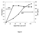
- Figure 4 is a graph depicting the results of an experiment to measure breakthrough of HCP and MAb following depth filtration prior to loading on the Protein A continuous multicolumn chromatography (CMC) set up.
- the x-axis denotes the depth filter load (L/m 2 ) and the left y-axis denotes MAb concentration (mg/ml) and the right y-axis denotes the HCP concentration ( ⁇ g/ml).
- Figure 5 is a schematic depiction of the flow-through purification process step, as further described in Example 3.
- Figure 6 is a graph depicting the results of an experiment to measure pressure profiles after depth filter, activated carbon and virus filtration.
- the y-axis denotes pressure (psi) and the x-axis denotes time in hours.
- Figure 7 is a graph depicting the results of an experiment to measure HCP breakthrough after AEX loading.
- the x-axis denotes HCP concentration (ppm) and the y-axis denotes the AEX loading (kg/L).
- Figure 8 is a graph depicting the results of an experiment to measure removal of MAb aggregates as a function of loading of the virus filtration device in the flow-through purification process step.
- the x-axis denotes the virus filtration loading (kg/m 2 ) and the y-axis denotes percentage of MAb aggregates in the sample after virus filtration.
- Figure 9 is a graph depicting the results of an experiment to measure pressure profiles after activated carbon and before virus filtration, as part of the flow-through purification process step.
- the x-axis denotes time in hours and the y-axis denotes pressure in psi.
- Figure 10 is a graph depicting the results of an experiment to measure pH and conductivity profiles, where pH is measured before activated carbon and is measured before CEX flow-through device and the conductivity is measured before CEX flow-through device.
- the left y-axis denotes pH and the right y-axis denotes conductivity (mS/cm) and the x-axis denotes time in hours.
- Figure 11 is a chromatogram for Protein A capture of untreated clarified MAb04 using CMC which employs two separation units.
- Figure 12 is a chromatogram for Protein A capture of smart-polymer clarified MAb04 using CMC which employs two separation units.
- Figure 13 is a chromatogram for Protein A capture of caprylic acid clarified MAb04 using CMC which employs two separation units.
- Figure 14 is a graph depicting the results of an experiment to investigate the effect of residence time on HCP removal using activated carbon and a anion exchange chromatography (AEX) device, as part of the flow-through purification step.
- the y-axis denotes HCP concentration (ppm) and the x-axis denotes AEX load (kg/L).
- Figure 15 is a graph depicting the results of an experiment to measure the effect on pH spike after using a surge tank between the flow-through anion exchange chromatography and cation exchange chromatography steps in a flow-through purification process step.
- the x-axis denotes pH and y-axis denotes time in hours.
- Figure 16 is a schematic depiction of the experimental set up used for demonstrating that running the flow-through purification process step in a continuous manner does not have a detrimental effect on product purity.
- Figure 17 is a graph depicting the results of an experiment to investigate pressure profiles after virus filtration, following use of the virus filtration device in a continuous format and in batch mode.
- the y-axis denotes pressure in psi and the x-axis denotes processing time in hours.
- Figure 18 is a graph depicting the results of an experiment to investigate effect of flow-rate on throughput of the virus filtration device.
- the y-axis denotes pressure drop (psi) and the x-axis denotes throughput of the virus filtration device (Kg/m 2 ).
- the present invention provides processes and systems which overcome several shortcomings associated with the typical templated processes used in the industry for purification of biological molecules such as antibodies.
- typical templated processes for purification of biological molecules include many different steps, including several chromatographic steps, and require use of holding or pool tanks between steps as well as take more than one day to complete.
- PCT Patent Publication No. WO 2012/014183 discusses methods for protein purification in which two or more chromatographic separation modes are combined in tandem.
- U.S. Patent Publication No. 2008/0269468 discusses combining a continuous perfusion fermentation system with a continuous particle removal system and a continuous purification system, where the flow rate of the mixture through the whole process is kept substantially constant.
- PCT Publication No. WO2012/078677 suggests a continuous process for manufacture of biological molecules; however, appears to focus on the provision of suitable equipment like multi-valve arrays. All process steps that are described in a general way and resemble the process steps known for batch processes. No hint is given how these process steps could befavorably combined or favorably performed to reach an efficient continuous or semi-continuous process. Lastly, the aforementioned PCT also fails to describe a continuous process that can be performed successfully with minimum interventions, as per the processes described herein.
- the present invention also provides other advantages over conventional processes used in the industry today, in that in the processes and systems according to the present invention, fewer solution adjustments (e.g., change in pH or conductivity) are needed throughout the entire process, thereby significantly reducing the number of process steps as well as the need to use large pool tanks between process steps for solution adjustments. In case of the processes and systems described herein, it is not required to perform large volume dilutions in order to change conductivity, thereby obviating the need to use large pool tanks between process steps. Additionally, in some embodiments, the processes and systems described herein employ fewer control units (also called "skids”) compared to conventional processes used in the art.
- target molecule or “target compound” refers to any molecule, substance or compound or mixtures thereof that is isolated, separated or purified from one or more impurities in a sample using processes and systems described herein.
- the target molecule is a biological molecule such as, e.g., a protein or a mixture of two or more proteins.
- the target molecule is an Fc-region containing protein such as an antibody.
- antibody refers to a protein which has the ability to specifically bind to an antigen.
- antibodies are having a basic four-polypeptide chain structure consisting of two heavy and two light chains, said chains being stabilized, for example, by interchain disulfide bonds.
- Antibodies may be monoclonal or polyclonal and may exist in monomeric or polymeric form, for example, IgM antibodies which exist in pentameric form and/or IgA antibodies which exist in monomeric, dimeric or multimeric form.
- Antibodies may also include multispecific antibodies (e.g., bispecific antibodies), and antibody fragments so long as they retain, or are modified to comprise, a ligand-specific binding domain.
- fragment refers to a part or portion of an antibody or antibody chain comprising fewer amino acid residues than an intact or complete antibody or antibody chain. Fragments can be obtained via chemical or enzymatic treatment of an intact or complete antibody or antibody chain. Fragments can also be obtained by recombinant means. When produced recombinantly, fragments may be expressed alone or as part of a larger protein called a fusion protein. Exemplary fragments include Fab, Fab', F(ab')2, Fc and/or Fv fragments.
- an Fc-region containing protein is a recombinant protein which includes the Fc region of an immunoglobulin fused to another polypeptide or a fragment thereof.
- Exemplary polypeptides include, e.g., renin; a growth hormone, including human growth hormone and bovine growth hormone; growth hormone releasing factor; parathyroid hormone; thyroid stimulating hormone; lipoproteins; ⁇ - 1 -antitrypsin; insulin ⁇ -chain; insulin ⁇ -chain; proinsulin; follicle stimulating hormone; calcitonin; luteinizing hormone; glucagon; clotting factors such as factor VIIIC, factor IX, tissue factor, and von Willebrands factor; anti-clotting factors such as Protein C; atrial natriuretic factor; lung surfactant; a plasminogen activator, such as urokinase or human urine or tissue-type plasminogen activator (t-PA); bombesin; thrombin; hemopoietic growth factor
- sample refers to any composition or mixture that contains a target molecule.
- Samples may be derived from biological or other sources.
- Biological sources include eukaryotic and prokaryotic sources, such as plant and animal cells, tissues and organs.
- the sample may also include diluents, buffers, detergents, and contaminating species, debris and the like that are found mixed with the target molecule.
- the sample may be "partially purified” (i.e., having been subjected to one or more purification steps, such as filtration steps) or may be obtained directly from a host cell or organism producing the target molecule (e.g., the sample may comprise harvested cell culture fluid).
- a sample is a cell culture feed.
- impurity refers to any foreign or objectionable molecule, including a biological macromolecule such as DNA, RNA, one or more host cell proteins, endotoxins, lipids and one or more additives which may be present in a sample containing the target molecule that is being separated from one or more of the foreign or objectionable molecules using a process of the present invention. Additionally, such impurity may include any reagent which is used in a step which may occur prior to the method of the invention. An impurity may be soluble or insoluble in nature.
- insoluble impurity refers to any undesirable or objectionable entity present in a sample containing a target molecule, where the entity is a suspended particle or a solid.
- exemplary insoluble impurities include whole cells, cell fragments and cell debris.
- soluble impurity refers to any undesirable or objectionable entity present in a sample containing a target molecule, where the entity is not an insoluble impurity.
- soluble impurities include host cell proteins, DNA, RNA, viruses, endotoxins, cell culture media components, lipids etc.
- CHOP Choinese hamster ovary cell protein
- HCP host cell proteins
- CHOP is generally present as an impurity in a cell culture medium or lysate (e.g., a harvested cell culture fluid ("HCCF”)) comprising a target molecule such as an antibody or immunoadhesin expressed in a CHO cell).
- HCCF harvested cell culture fluid
- the amount of CHOP present in a mixture comprising a target molecule provides a measure of the degree of purity for the target molecule.
- HCP or CHOP includes, but is not limited to, a protein of interest expressed by the host cell, such as a CHO host cell.
- the amount of CHOP in a protein mixture is expressed in parts per million relative to the amount of the target molecule in the mixture.
- HCP refers to the proteins, other than target protein, found in a lysate of the host cell.
- ppm parts per million
- purifying refers to increasing the degree of purity of a target molecule from a sample comprising the target molecule and one or more impurities. Typically, the degree of purity of the target molecule is increased by removing (completely or partially) at least one impurity from the sample.
- binding and elute mode and "bind and elute process,” as used herein, refer to a separation technique in which at least one target molecule contained in a sample (e.g., an Fc region containing protein) binds to a suitable resin or media (e.g., an affinity chromatography media or a cation exchange chromatography media) and is subsequently eluted.
- a suitable resin or media e.g., an affinity chromatography media or a cation exchange chromatography media
- flow-through process refers to a separation technique in which at least one target molecule (e.g., an Fc-region containing protein or an antibody) contained in a biopharmaceutical preparation along with one or more impurities is intended to flow through a material, which usually binds the one or more impurities, where the target molecule usually does not bind (i.e., flows through).
- target molecule e.g., an Fc-region containing protein or an antibody
- process step refers to the use of one or more methods or devices to achieve a certain result in a purification process.
- process steps or unit operations which may be employed in the processes and systems described herein include, but are not limited to, two or more process steps selected from, clarification, bind and elute chromatography, virus inactivation, flow-through purification and formulation. It is understood that each of the process steps or unit operations may employ more than one step or method or device to achieve the intended result of that process step or unit operation.
- the clarification step or the flow-through purification step as described herein, may employ more than one step or method or device to achieve that process step or unit operation.
- one or more devices which are used to perform a process step or unit operation are disposable and can be removed and/or replaced without having to replace any other devices in the process or or even having to stop a process run.
- system generally refers to the physical form of the whole purification process, which includes two or more process steps or unit operations, as described herein. In some embodiments, the system is enclosed in a sterile environment.
- a separation unit refers to an equipment or apparatus, which can be used in a bind and elute chromatographic separation or a flow-through step or a filtration step.
- a separation unit can be a chromatography column or a chromatography cartridge which is filled with a sorbent matrix or a chromatographic device that contains a matrix that has appropriate functionality.
- a single bind and elute chromatography step is used in the purification process which employs two or more separation units.
- the processes and systems described herein obviate the need to necessarily use pool tanks, thereby significantly reducing the overall time to run a purification process as well as the overall physical footprint occupied by the system. Accordingly, in various embodiments according to the present invention, the output from one process step (or unit operation) is the input for a consecutive step (or unit operation) and flows directly and continuously into a consecutive process step (or unit operation), without the need for collecting the entire output from a process step.
- pool tank refers to any container, vessel, reservoir, tank or bag, which is generally used between process steps and has a size/volume to enable collection of the entire volume of output from a process step.
- Pool tanks may be used for holding or storing or manipulating solution conditions of the entire volume of output from a process step.
- the processes and systems described herein obviate the need to use one or more pool tanks.
- the processes and systems described herein may use one or more surge tanks throughout a purification process.
- surge tank refers to any container or vessel or bag, which is used between process steps or within a process step (e.g., when a single process step comprises more than one step); where the output from one step flows through the surge tank onto the next step.
- a surge tank is different from a pool tank, in that it is not intended to hold or collect the entire volume of output from a step; but instead enables continuous flow of output from one step to the next.
- the volume of a surge tank used between two process steps or within a process step in a process or system described herein is no more than 25% of the entire volume of the output from the process step.
- the volume of a surge tank is no more than 10% of the entire volume of the output from a process step. In some other embodiments, the volume of a surge tank is less than 35%, or less than 30%, or less than 25%, or less than 20%, or less than 15%, or less than 10% of the entire volume of a cell culture in a bioreactor, which constitutes the starting material from which a target molecule is to be purified.
- continuous process refers to a process for purifying a target molecule, which includes two or more process steps (or unit operations), such that the output from one process step flows directly into the next process step in the process, without interruption and/or without the collection of the entire volume of output from the process step e.g. in a pool tank, and where two or more process steps can be performed concurrently for at least a portion of their duration.
- two or more process steps of a continuous process are performed concurrently for at least a portion of their duration.
- continuous process also applies to steps within a process step, in which case, during the performance of a process step including multiple steps, the sample flows continuously through the multiple steps that are necessary to perform the process step.
- a process step described herein is the flow through purification step which includes multiple steps that are performed in a continuous manner, e.g., flow-through activated carbon followed by flow-through AEX media followed by flow-through CEX media followed by flow-through virus filtration.
- the term "semi-continuous process,” as used herein, refers to a generally continuous process for purifying a target molecule, where input of the fluid material in any single process step or the output is discontinuous or intermittent.
- the input in a process step e.g., a bind and elute chromatography step
- the output may be collected intermittently, where the other process steps in the purification process are continuous.
- the processes and systems described herein are "semi-continuous" in nature, in that they include at least one unit operation which is operated in an intermittent matter, whereas the other unit operations in the process or system may be operated in a continuous manner.
- connected process refers to a process for purifying a target molecule, where the process comprises two or more process steps (or unit operations), which are in fluid communication with each other, such that fluid material continuously flows through the process step in the process and is in simultaneous contact with two or more process steps during the normal operation of the process. It is understood that at times, at least one process step in the process may be temporarily isolated from the other process steps by a barrier such as a valve in the closed position. This temporary isolation of individual process steps may be necessary, for example, during start up or shut down of the process or during removal/replacement of individual unit operations.
- connected process also applies to steps within a process step, e.g., when a process step requires several steps to be performed in order to achieve the intended result of the process step.
- a process step requires several steps to be performed in order to achieve the intended result of the process step.
- One such example is the flow-through purification process step, as described herein, which may include several steps to be performed in a flow-through mode, e.g., activated carbon; anion exchange chromatography, cation exchange chromatography and virus filtration.
- fluid communication refers to the flow of fluid material between two process steps or flow of fluid material between steps of a process step, where the process steps are connected by any suitable means (e.g. a connecting line), thereby to enable the flow of fluid from one process step to another process step.
- Fluid communication thus means that fluid can flow from a part of the system to another, e.g. from one device to another, typically via one or more connecting lines.
- a connecting line between two unit operations may be interrupted by one or more valves to control the flow of fluid through the connecting line, by a surge tank, a detector, a pump etc.
- in fluid communication encompasses a fluid communication that is permanent but it also encompasses a fluid communication that is not permanent and is made of a connecting line that is e.g. interrupted by one or more valves so that the flow of liquid through the connecting line can started and stopped whenever necessary.
- a connecting line that is e.g. interrupted by one or more valves so that the flow of liquid through the connecting line can started and stopped whenever necessary.
- most of the parts of the apparatus that are in fluid communication have a fluid communication that is not permanent. If a flow of liquid is actually realized between two parts of the system that are in liquid communication and thus liquid is flowing through the connecting line between the two parts, these two parts are in "current fluid communication". Consequently, "current fluid communication" according to the present invention describes the status in which a "fluid communication" is actually used by flowing liquid through the connecting line.
- a "connecting line” is any tube, hose, pipe or channel or other device which is suitable for flowing liquids there through.
- a connecting line can be interrupted by one or more valves, surge tanks or other devices.
- a connecting line might be straight or branched.
- the terms "clarify,” “clarification,” and “clarification step,” as used herein, refers to a process step for removing suspended particles and or colloids, thereby to reduce turbidity, of a target molecule containing solution, as measured in NTU (nephelometric turbidity units). Clarification can be achieved by a variety of means, including centrifugation or filtration. Centrifugation could be done in a batch or continuous mode, while filtration could be done in a normal flow (e.g. depth filtration) or tangential flow mode. In processes used in the industry today, centrifugation is typically followed by depth filters intended to remove insoluble impurities, which may not have been removed by centrifugation.
- clarification involves any combinations of two or more of centrifugation, filtration, depth filtration and precipitation. In some embodiments, the processes and systems described herein obviate the need for centrifugation.
- precipitate refers to process used in clarification , in which the properties of the undesirable impurities are modified such that they can be more easily separated from the soluble target molecule, e.g. by causing the precipitation of a compound from a soluble state to a non-soluble state or by agglutinating and/or aggregating fine particles from a solution so that their settling and/or filtration and/or centrifugation is improved and thus a reduction of the turbidity is reached. This is typically accomplished by forming large aggregate particles and/or insoluble complexes containing the undesirable impurities. These particles have properties (e.g.
- phase change is effected, such that the undesirable impurities can be more easily separated from the soluble target molecule.
- Precipitation by phase change can be effected by the addition of a precipitating agent, such as a polymer or a small molecule.
- the precipitant is a stimulus responsive polymer, also referred to as a smart polymer.
- the precipitant or precipitating agent is a flocculant.
- Flocculation as used herein, is one way of performing precipitation where the performance typically depends on the flocculant concentration used ("dose dependent"). Typical flocculating agents are polyelectrolytes, such as polycations, that complex with oppositely charged impurities.
- clarification employs the addition of a precipitant to a sample containing a target molecule and one or more impurities.
- a change in solution conditions such as temperature, pH, salinity
- the precipitated material which contains the one or more impurities as well as the precipitating agent is removed thereby recovering the target molecule in the liquid phase, where the liquid is then typically subjected to further process steps in order to further purify the target molecule.
- Precipitation may be performed directly in a bioreactor containing a cell culture expressing a target molecule to be purified, where a precipitant is added directly to the bioreactor.
- the precipitant may be added to the cell culture, which typically contains the target molecule, in a separate vessel.
- settling refers to a sedimentation process in which the precipitated material migrates to the bottom of a vessel under the influence of gravitational forces. Settling can be followed by decanting and/or filtering of the liquid phase or supernatant.
- a stimulus or “stimuli,” as used interchangeably herein, is meant to refer to a physical or chemical change in the environment which results in a response by a stimulus responsive polymer. Accordingly, such polymers are responsive to a stimulus and which stimulus results in a change in the solubility of the polymer.
- Examples of stimuli to which one or more polymers used herein are responsive include, but are not limited to, e.g., changes in temperature, changes in conductivity and/or changes in pH.
- a stimulus comprises addition of a complexing agent or a complex forming salt to a sample.
- a stimulus is generally added after the addition of a polymer to a sample. Although, the stimulus may also be added during or before addition of a polymer to a sample.
- a stimulus responsive polymer refers to a polymer or copolymer which exhibits a change in a physical and/or chemical property after the addition of a stimulus.
- a typical stimulus response is a change in the polymer's solubility.
- the polymer poly(N-isopropylacrylamide) is water soluble at temperatures below about 35° C, but become insoluble in water at temperatures of about 35° C.
- a stimulus responsive polymer is a polyallylamine or a polyvinylamine polymer which is responsive to a multivalent ion stimulus (e.g, phosphate stimulus).
- a cell culture is subjected to a depth filter to remove one or more impurities.
- depth filter or “depth filtration” as used herein refer to a filter that is capable of retaining particulate matter throughout the filter medium, rather than just on the filter surface. In some embodiments described herein, one or more depth filters are used in the clarification process step.
- clarification results in the removal of soluble and/or insoluble impurities in a sample which may later on result in the fouling of a filter or device used in a process step in a purification process, thereby making the overall purification process more economical.
- one or more chromatography steps are included in a protein purification process.
- chromatography refers to any kind of technique which separates an analyte of interest (e.g. a target molecule) from other molecules present in a mixture through differential adsorption onto a matrix.
- analyte of interest e.g. a target molecule
- the target molecule is separated from other molecules as a result of differences in rates at which the individual molecules of the mixture migrate through a stationary medium under the influence of a moving phase, or in bind and elute processes.
- matrix refers to any kind of particulate sorbent, media, resin or other solid phase (e.g., a membrane, non-woven, monolith, etc.) which in a separation process, acts as the adsorbent to separate a target molecule (e.g., an Fc region containing protein such as an immunoglobulin) from other molecules present in a mixture (e.g., one or more impurities)), or alternatively, acts as a sieve to separate molecules based on size (e.g., in case of a virus filtration membrane).
- a target molecule e.g., an Fc region containing protein such as an immunoglobulin
- a mixture e.g., one or more impurities
- the target molecule is separated from other molecules as a result of differences in rates at which the individual molecules of the mixture migrate through the matrix under the influence of a moving phase.
- the matrix e.g. consisting of resin particles, can be put in columns or cartridges.
- materials for forming the matrix include polysaccharides (such as agarose and cellulose); and other mechanically stable matrices such as silica (e.g. controlled pore glass), poly(styrenedivinyl)benzene, polyacrylamide, ceramic particles and derivatives of any of the above.
- Matrices may or may not contain ligands.
- a matrix includes an affinity ligand such as, e.g., Protein A.
- affinity ligand such as, e.g., Protein A.
- matrices that may be used in the processes described herein that do not contain a ligand include, but are not limited to, activated carbon, hydroxyapatite, silica, etc.
- ligand refers to a functional group that is attached to a matrix and that determines the binding properties of the matrix.
- ligands include, but are not limited to, ion exchange groups, hydrophobic interaction groups, hydrophilic interaction groups, thiophilic interactions groups, metal affinity groups, affinity groups, bioaffinity groups, and mixed mode groups (combinations of the aforementioned).
- exemplary ligands which may be used include, but are not limited to, strong cation exchange groups, such as sulphopropyl, sulfonic acid; strong anion exchange groups, such as trimethylammonium chloride; weak cation exchange groups, such as carboxylic acid; weak anion exchange groups, such as N 5 N diethylamino or DEAE; hydrophobic interaction groups, such as phenyl, butyl, propyl, hexyl; and affinity groups, such as Protein A, Protein G, and Protein L.
- the ligand that is used in the processes and systems described herein is Protein A or a functional variant or fragment thereof, as described in U.S. Patent Applications Nos.
- affinity chromatography refers to a protein separation technique in which a target molecule (e.g., an Fc region containing protein of interest or antibody) specifically binds to a ligand which is specific for the target molecule.
- a target molecule e.g., an Fc region containing protein of interest or antibody
- a ligand which is specific for the target molecule.
- a ligand is generally referred to as a biospecific ligand.
- the biospecific ligand e.g., Protein A or a functional variant thereof
- suitable chromatography matrix material is accessible to the target molecule in solution as the solution contacts the chromatography matrix.
- the target molecule generally retains its specific binding affinity for the biospecific ligand during the chromatographic steps, while other solutes and/or proteins in the mixture do not bind appreciably or specifically to the ligand. Binding of the target molecule to the immobilized ligand allows contaminating proteins and impurities to be passed through the chromatography matrix while the target molecule remains specifically bound to the immobilized ligand on the solid phase material. The specifically bound target molecule is then removed in its active form from the immobilized ligand under suitable conditions (e.g., low pH, high pH, high salt, competing ligand etc.), and passed through the chromatographic column with the elution buffer, substantially free of the contaminating proteins and impurities that were earlier allowed to pass through the column.
- suitable conditions e.g., low pH, high pH, high salt, competing ligand etc.
- any suitable ligand may be used for purifying its respective specific binding protein, e.g. antibody.
- Protein A is used as a ligand for an Fc region containing target protein.
- the conditions for elution from the biospecific ligand (e.g., Protein A) of the target molecule (e.g., an Fc- region containing protein) can be readily determined by one of ordinary skill in the art.
- Protein G or Protein L or a functional variant thereof may be used as a biospecific ligand.
- a process which employs a biospecific ligand such as Protein A uses a pH range of 5-9 for binding to an Fc-region containing protein, followed by washing or re-equilibrating the biospecific ligand / target molecule conjugate, which is then followed by elution with a buffer having pH about or below 4 which contains at least one salt.
- Protein A and “Prot A” are used interchangeably herein and encompasses Protein A recovered from a native source thereof, Protein A produced synthetically (e.g., by peptide synthesis or by recombinant techniques), and variants thereof which retain the ability to bind proteins which have a CH 2 /CH 3 region, such as an Fc region.
- Protein A can be purchased commercially from Repligen, GE or Fermatech. Protein A is generally immobilized on a chromatography matrix.
- An interaction compliant with such value for the binding constant is termed "high affinity binding" in the present context.
- such functional derivative or variant of Protein A comprises at least part of a functional IgG binding domain of wild-type Protein A, selected from the natural domains E, D, A, B, C or engineered mutants thereof which have retained IgG binding functionality.
- Protein A derivatives or variants engineered to allow a single-point attachment to a solid support may also be used in the affinity chromatography step in the claimed methods.
- Single point attachment generally means that the protein moiety is attached via a single covalent bond to a chromatographic support material of the Protein A affinity chromatography. Such single-point attachment may also occur by use of suitably reactive residues which are placed at an exposed amino acid position, namely in a loop, close to the N- or C-terminus or elsewhere on the outer circumference of the protein fold. Suitable reactive groups are e.g. sulfhydryl or amino functions.
- Protein A derivatives of variants are attached via multi-point attachment to suitable a chromatography matrix.
- affinity chromatography matrix refers to a chromatography matrix which carries ligands suitable for affinity chromatography.
- the ligand e.g., Protein A or a functional variant or fragment thereof
- an affinity chromatography matrix is a ProteinA matrix.
- An affinity chromatography matrix typically binds the target molecules with high specificity based on a lock/key mechanism such as antigen/antibody or enzyme/receptor binding.
- affinity matrices are matrices carrying protein A ligands like Protein A SEPHAROSETM or PROSEP®-A.
- an affinity chromatography step may be used as the bind and elute chromatography step in the entire purification process.
- ion-exchange and ion-exchange chromatography refer to the chromatographic process in which a solute or analyte of interest (e.g., a target molecule being purified) in a mixture, interacts with a charged compound linked (such as by covalent attachment) to a solid phase ion exchange material, such that the solute or analyte of interest interacts non-specifically with the charged compound more or less than solute impurities or contaminants in the mixture.
- contaminating solutes in the mixture elute from a column of the ion exchange material faster or slower than the solute of interest or are bound to or excluded from the resin relative to the solute of interest.
- Ion-exchange chromatography specifically includes cation exchange, anion exchange, and mixed mode ion exchange chromatography.
- cation exchange chromatography can bind the target molecule (e.g., an Fc region containing target protein) followed by elution (e.g., using cation exchange bind and elute chromatography or "CIEX”) or can predominately bind the impurities while the target molecule "flows through” the column (cation exchange flow through chromatography FT- CIEX).
- Anion exchange chromatography can bind the target molecule (e.g., an Fc region containing target protein) followed by elution or can predominately bind the impurities while the target molecule "flows through” the column, also referred to as negative chromatography.
- the anion exchange chromatography step is performed in a flow through mode.
- ion exchange matrix refers to a matrix that is negatively charged (i.e., a cation exchange media) or positively charged (i.e., an anion exchange media).
- the charge may be provided by attaching one or more charged ligands to the matrix, e.g., by covalent linkage.
- the charge may be an inherent property of the matrix (e.g., as is the case of silica, which has an overall negative charge).
- anion exchange matrix is used herein to refer to a matrix which is positively charged, e.g. having one or more positively charged ligands, such as quaternary amino groups, attached thereto.
- commercially available anion exchange resins include DEAE cellulose, QAE SEPHADEXTM and FAST Q SEPHAROSETM (GE Healthcare).
- Other exemplary materials that may be used in the processes and systems described herein are Fractogel® EMD TMAE, Fractogel® EMD TMAE highcap, Eshmuno® Q and Fractogel® EMD DEAE (EMD Millipore).
- cation exchange matrix refers to a matrix which is negatively charged, and which has free cations for exchange with cations in an aqueous solution contacted with the solid phase of the matrix.
- a negatively charged ligand attached to the solid phase to form the cation exchange martrix or resin may, for example, be a carboxylate or sulfonate.
- Commercially available cation exchange matrices include carboxy-methyl-cellulose, sulphopropyl (SP) immobilized on agarose (e.g., SP-SEPHAROSE FAST FLOWTM or SP-SEPHAROSE HIGH PERFORMANCETM, from GE Healthcare) and sulphonyl immobilized on agarose (e.g.
- Fractogel® EMD SO 3 is Fractogel® EMD SO 3 , Fractogel® EMD SE Highcap, Eshmuno® S and Fractogel® EMD COO (EMD Millipore).
- mixed-mode chromatography or “multi-modal chromatography,” as used herein, refers to a process employing a chromatography stationary phase that carries at least two distinct types of functional groups, each capable of interacting with a molecule of interest.
- An example of mixed mode chromatography media is CaptoTM Adhere (GE Healthcare), which is an AEX mixed mode resin.
- Mixed-mode chromatography generally employs a ligand with more than one mode of interaction with a target protein and/or impurities. The ligand typically includes at least two different but cooperative sites which interact with the substance to be bound.
- one of these sites may have a charge-charge type interaction with the substance of interest, whereas the other site may have an electron acceptor-donor type interaction and/or hydrophobic and/or hydrophilic interactions with the substance of interest.
- Electron donor-acceptor interaction types include hydrogen-bonding, ⁇ - ⁇ , cation- ⁇ , charge transfer, dipole-dipole and induced dipole interactions.
- a target protein and one or more impurities may be separated under a range of conditions.
- mixed mode ion exchange matrix refers to a matrix which is covalently modified with cationic and/or anionic and hydrophobic moieties.
- a commercially available mixed mode ion exchange resin is BAKERBOND ABXTM (J. T. Baker, Phillipsburg, N.J.) containing weak cation exchange groups, a low concentration of anion exchange groups, and hydrophobic ligands attached to a silica gel solid phase support matrix.
- Mixed mode cation exchange materials typically have cation exchange and hydrophobic moieties. Suitable mixed mode cation exchange materials are Capto® MMC (GE Healthcare) and Eshmuno® HCX (EMD Millipore).
- Mixed mode anion exchange materials typically have anion exchange and hydrophobic moieties. Suitable mixed mode anion exchange materials are Capto® Adhere (GE Healthcare).
- hydrophobic interaction chromatography refers to a process for separating molecules based on their hydrophobicity, i.e., their ability to adsorb to hydrophobic surfaces from aqueous solutions.
- HIC is usually differentiated from the Reverse Phase (RP) chromatography by specially designed HIC resins that typically have a lower hydrophobicity, or density of hydrophobic ligands compared to RP resins.
- HIC chromatography typically relies on the differences in hydrophobic groups on the surface of solute molecules. These hydrophobic groups tend to bind to hydrophobic groups on the surface of an insoluble matrix. Because HIC employs a more polar, less denaturing environment than reversed phase liquid chromatography, it is becoming increasing popular for protein purification, often in combination with ion exchange or gel filtration chromatography.
- break-through refers to the point of time during the loading of a sample containing a target molecule onto a packed chromatography column or separation unit, when the target molecule first appears in the output from the column or separation unit.
- break-through is the point of time when loss of target molecule begins.
- a “buffer” is a solution that resists changes in pH by the action of its acid-base conjugate components.
- Various buffers which can be employed depending, for example, on the desired pH of the buffer, are described in: Buffers. A Guide for the Preparation and Use of Buffers in Biological Systems, Gueffroy, D., ed. Calbiochem Corporation (1975 ).
- Non- limiting examples of buffers include MES, MOPS, MOPSO, Tris, HEPES, phosphate, acetate, citrate, succinate, and ammonium buffers, as well as combinations of these.
- a buffer When "loading" a sample onto a device or a column or a separation unit containing a suitable matrix, a buffer is used to load the sample comprising the target molecule and one or more impurities onto the device or column or separation unit.
- the buffer In the bind and elute mode, the buffer has a conductivity and/or pH such that the target molecule is bound to matrix, while ideally all the impurities are not bound and flow through the column.
- a buffer in a flow-through mode, is used to load the sample comprising the target molecule and one or more impurities onto a column or device or separation unit, wherein the buffer has a conductivity and/or pH such that the target molecule is not bound to the matrix and flows through while ideally all or most of the impurities bind to the matrix.
- re-equilibrating refers to the use of a buffer to recondition the matrix prior to loading the target molecule.
- the same buffer used for loading may be used for re-equilibrating.
- wash or “washing” a chromatography matrix refers to passing an appropriate liquid, e.g., a buffer, through or over the matrix. Typically washing is used to remove weakly bound contaminants from the matrix prior to eluting the target molecule and/or to remove non-bound or weakly bound target molecule after loading.
- the wash buffer is different from the loading buffer.
- the wash buffer and the loading buffer are the same.
- a wash step is eliminated from the purification process by altering the conditions of the loading buffer or fewer wash steps are used.
- elute or “eluting” or “elution” refers to removal of a molecule (e.g., a polypeptide of interest or an impurity) from a chromatography matrix by using or altering certain solution conditions, whereby the buffer (referred to as an “elution buffer”) competes with the molecule of interest for the ligand sites on the chromatography resin.
- elution buffer a buffer that competes with the molecule of interest for the ligand sites on the chromatography resin.
- a non-limiting example is to elute a molecule from an ion exchange resin by altering the ionic strength of the buffer surrounding the ion exchange material such that the buffer competes with the molecule for the charged sites on the ion exchange material.
- virus inactivation buffer may be used to inactivate certain viruses prior to eluting the target molecule.
- the virus inactivation buffer differs from loading buffer since it may contain detergent/detergents or have different properties (pH/conductivity/salts and their amounts).
- virus inactivation is performed before the bind and elute chromatography step.
- virus inactivation is performed during or after elution from a bind and elute chromatography step.
- virus inactivation is performed in-line using a static mixer.
- virus inactivation employs use of one or more surge tanks.
- bioreactor refers to any manufactured or engineered device or system that supports a biologically active environment.
- a bioreactor is a vessel in which a cell culture process is carried out which involves organisms or biochemically active substances derived from such organisms. Such a process may be either aerobic or anaerobic.
- Commonly used bioreactors are typically cylindrical, ranging in size from liters to cubic meters, and are often made of stainless steel.
- a bioreactor is made of a material other than steel and is disposable. It is contemplated that the total volume of a bioreactor may be any volume ranging from 100 mL to up to 10,000 Liters or more, depending on a particular process.
- the bioreactor is connected to a unit operation such as a depth filter.
- a bioreactor is used for both cell culturing as well as for precipitation, where a precipitant may be added directly to a bioreactor, thereby to precipitate one or more impurities.
- active carbon refers to a carbonaceous material which has been subjected to a process to enhance its pore structure.
- Activated carbons are porous solids with very high surface areas. They can be derived from a variety of sources including coal, wood, coconut husk, nutshells, and peat. Activated carbon can be produced from these materials using physical activation involving heating under a controlled atmosphere or chemical activation using strong acids, bases, or oxidants. The activation processes produce a porous structure with high surface areas that give activated carbon high capacities for impurity removal. Activation processes can be modified to control the acidity of the surface.
- activated carbon is used in a flow through purification step, which typically follows a bind and elute chromatography step or a virus inactivation step which in turn follows the bind and elute chromatography step.
- static mixer refers to a device for mixing two fluid materials, typically liquids.
- the device typically consists of mixer elements contained in a cylindrical (tube) housing.
- the overall system design incorporates a method for delivering two streams of fluids into the static mixer. As the streams move through the mixer, the non-moving elements continuously blend the materials. Complete mixing depends on many variables including the properties of the fluids, inner diameter of the tube, number of mixer elements and their design etc.
- one or more static mixers are used throughout the purification process or system.
- a static mixer is used for contacting the output from the bind and elute chromatography step with a virus inactivating agent (e.g., an acid or any other suitable virus inactivating agent), where the use of a static mixer significantly reduces the time, which would otherwise be needed to accomplish effective virus inactivation.
- a virus inactivating agent e.g., an acid or any other suitable virus inactivating agent
- the present invention provides novel and improved processes for purification of target molecules from a sample (e.g., a cell culture feed) containing a target molecule and one or more impurities.
- a sample e.g., a cell culture feed
- the processes described herein are a vast improvement over existing methods used in the art, in that they reduce the overall time frame required for a process run (12-24 hours relative to several days); include fewer steps relative to most conventional processes; reduce the overall physical footprint of a process by virtue of having fewer unit operations and are easier to execute than a conventional process. Additionally, in some embodiments, processes according to the present invention employ devices that may be disposable.
- the processes according to the present invention include several process steps which are intended to achieve a desired result (also referred to as a unit operation), and where the process steps (or unit operations) are connected such that to be in fluid communication with each other and further that two or more process steps can be performed concurrently for at least a part of the duration of each process step.
- a user does not have to wait for a process step to be completed before executing the next process step in the process, but a user can start a process run such that the liquid sample containing the target molecule flows through the process steps continuously or semi-continuously, resulting in a purified target molecule.
- the sample containing the target molecule is typically in contact with more than one process step in the process at any given time.
- Each process step (or unit operation) may involve the use of one or more devices or methods to accomplish the process step (or unit operation).
- the processes described herein are different from conventional processes used in the industry, in that they obviate the need to use pool tanks for holding, diluting, manipulating and sometimes storing the output from a process step before the output is subjected to the next process step.
- the processes described herein enable any manipulation of the sample in-line (e.g., using a static mixer) or employ the use of surge tanks (which are usually not more than 10% or 20% or 25% of total volume of the output from a process step) between process steps or sometimes within a process step (e.g., when a single process step employs more than one method or device), thereby significantly reducing the overall time to perform the process as well as the physical footprint of the overall system for performing the process.
- the process according to the present invention uses no pool tanks but only surge tanks with a volume of less than 25%, preferably less than 10% of the volume of output from the preceding process step.
- the process according to the present invention comprises at least three basic process steps - one clarification step, one bind-and-elute chromatography step and one flow-through purification step.
- the clarification step is the first process step, followed by the bind-and-elute chromatography step which is then followed by the flow-through purification step.
- the process may also comprise one or more additional optional process steps like virus inactivation steps, formulation steps, filtration steps or others which can be performed prior to and/or after and/or between the three basic process steps. While the process according to the present invention might involve additional process steps as described above it has to be noted that one important feature of the process is that in any case it has only one bind-and-elute chromatography step.
- process steps or unit operations are performed in a continuous or semi-continuous manner, as described herein.
- process steps which may be used in the process according to the present invention. It is understood that any combinations of the process steps shown below can be used. In other words, any process step under Step 1 in the Table I below may be combined with any process step under Step 2 and/or any process step under Step 3 and so forth. It is also understood that additional process steps, which are described elsewhere in the specification may be combined with or used instead of one or more of the process steps described in Table I below.
- the samples containing the target molecules that are purified with the process according to the present invention are typically resulting from cell culture, like transgenic mammalian cell cultures, bacterial cell cultures, nontransgenic mammalian cell cultures, tissue cultures, microbial fermentation batches, plant extracts, biofuel, seawater cultures, freshwater cultures, wastewater cultures, treated sewage, untreated sewage, milk cultures, blood cultures, and combinations thereof.
- the sample comprising the target molecule is the mixture present in a bioreactor when growing cells or microorganisms for producing the target molecule. Beside the target molecule the mixture typically comprises impurities like media components, cells, cellular debris, nucleic acids, host cell proteins etc.
- Clarification is intended to separate one or more soluble and/or insoluble impurities from the target molecule.
- insoluble impurities like cells and cellular debris are removed from the sample resulting in a clarified fluid containing the target molecule in solution as well as other soluble impurities.
- Clarification is typically performed prior to the bind-and-elute chromatography step involving capture of the desired target molecule.
- Another key aspect of clarification is the removal of soluble and/or insoluble impurities in a sample which may later on result in the fouling of a sterile filter in a purification process, thereby making the overall purification process more economical.
- the clarification step of the process according to the present invention involves at least the removal of one or more impurities by centrifugation and/or filtration and/or settling.
- clarification is done by filtration and/or settling and thus obviates the need to use centrifugation. Consequently it is preferred that the process according to the present invention is performed without doing centrifugation.
- the sample is first subjected to settling and the resulting supernatant liquid phase is then subjected to filtration.
- Filtration means any suitable type of filtration, preferably it means tangential flow filtration and/or depth filtration. In an especially preferred embodiment, filtration is depth filtration.
- Depth filters are typically used to remove one or more insoluble impurities. Depth filters are filters that use a porous filtration medium to retain particles throughout the medium, rather than just on the surface of the medium.
- a depth filter is used for clarification, which is capable of filtering cellular debris and particulate matter having a particle size distribution of about 0.5 ⁇ m to about 200 ⁇ m at a flow rate of about 10 liters/m 2 /hr to about 100 liters/m 2 /hr.
- the porous depth filter is anisotropic (i.e. with a gradual reduction in pore size).
- the pores have a nominal pore size rating > about 25 ⁇ m.
- the depth filter preferably comprises at least 2 graded layers of non-woven fibers, wherein the graded layers have a total thickness of about 0.3 cm to about 3 cm.
- the depth filters are configured in a device which is able to filter high solid feeds containing particles having a particle size distribution of approximately 0.5 ⁇ m to 200 ⁇ m at a flow rate of about 10 liters/m 2 /hr to about 100 liters/m 2 /hr until the transmembrane pressure (TMP) reaches 20 psi.
- TMP transmembrane pressure
- depth filters comprise a composite of graded layers of non-woven fibers, cellulose, and diatomaceous earth.
- the non-woven fibers comprise polypropylene, polyethylene, polyester, nylon or mixtures thereof.
- depth filters used in the clarification step include open graded layers, allowing the larger particles in the feed stream to penetrate into the depth of the filter, and become captured within the pores of the filter rather than collect on the surface.
- the open top layers of the graded depth filters enable capturing of larger particles, while the bottom layers enable capturing the smaller residual aggregated particles.
- Various advantages of the graded depth filters include a higher throughput, retention of larger solids and eliminating the problem of cake formation.
- sample volumes of less than 5000 liters preferably less than 2000 liters can be clarified by subjecting the sample to settling and depth filtration or depth filtration alone, without the need for centrifugation.
- one or more precipitants are added to the sample to precipitate one or more soluble and/or insoluble impurities prior to removing one or more impurities by centrifugation, filtration, settling or combinations thereof.
- Precipitation may include changing solution conditions (e.g., temperature, pH, salinity), acid precipitation, the use of a stimulus responsive polymer, flocculation or any other suitable means/agent for achieving precipitation of one or more impurities.
- suitable precipitants are organic acids (e.g. octanoic acid), inorganic acids (e.g. HCl), other acidic agents that substantially lower the pH towards acidic, salts (e.g., sodium benzoate, sodium chalate, sodium deoxychalate, etc.) other monovalent salts or organic acids which precipitate in the acidic medium).
- a precipitant is a short-chain fatty acid such as caprylic acid. In mildly acidic conditions, the addition of short-chain fatty acids such as caprylic acid typically precipitates non IgG proteins while IgG is not precipitated.
- Flocculation is one way of performing precipitation where the precipitation typically depends on the flocculant concentration used (i.e., is "dose dependent").
- Typical flocculating agents are polyelectrolytes, such as polycations, that complex with oppositely charged impurities.
- flocculants typically precipitate cells, cell debris and proteins because of the interaction between the charges on the cells/proteins and charges on the polymer (e.g. polyelectrolytes), thereby creating insoluble complexes.
- the polymer e.g. polyelectrolytes
- polyelectrolyte polymers in flocculation to purify proteins is well established in the art (see, e.g., International PCT Patent Application No. WO2008/091740 , incorporated by reference herein).
- Precipitation by flocculants can be accomplished with a wide range of polymers, with the only required general characteristic being the polymer must have some level of interaction with a species of interest (e.g., a target molecule or an impurity).
- exemplary flocculants include polymers such as chitosan and polysaccharides.
- Flocculation may also be achieved by chemical treatment resulting in changes in pH or by addition of a surfactant.
- stimulus responsive polymers are used as precipitants for precipitating one or more impurities.
- Examples of such stimulus responsive polymers can be found, e.g., in U.S. Publication Nos., 20080255027 , 20090232737 and 20110020327 ; and U.S. Patent No. 8,163,886 , all incorporated by reference herein.
- Stimulus responsive polymers are generally soluble in an aqueous based solvent under a certain set of process conditions such as pH, temperature and/or salt concentration and are rendered insoluble upon a change in one or more of such conditions and subsequently precipitate out.
- Exemplary stimulus responsive polymers include, but are not limited to, polyallylamine, polyallylamine modified with a benzyl group or polyvinylamine and polyvinylamine modified with a benzyl group, where the stimulus is phosphate or citrate.
- small molecules are used for precipitating one or more impurities, especially insoluble impurities.
- Small molecules used in the processes described herein are non-polar and cationic, e.g., as described in U.S. Provisional Patent Application No. 61/575,376, filing date August 19, 2011 , incorporated by reference herein.
- Exemplary small molecules that may be used for clarification include, but are not limited to, monoalkyltrimethyl ammonium salt (non-limiting examples include cetyltrimethylammonium bromide or chloride, tetradecyltrimethylammonium bromide or chloride, alkyltrimethyl ammonium chloride, alkylaryltrimethyl ammonium chloride, dodecyltrimethylammonium bromide or chloride, dodecyldimethyl-2-phenoxyethylammonium bromide, hexadecylamine chloride or bromide, dodecyl amine or chloride, and cetyldimethylethyl ammonium bromide or chloride), a monoalkyldimethylbenzyl ammoni
- the small molecule is benzethonium chloride (BZC).
- clarification is performed directly in a bioreactor.
- one or more precipitants e.g., a stimulus responsive polymer
- the liquid phase is then further subjected to centrifugation, filtration, settling or combinations thereof, preferably to depth filtration.
- the clarification step is performed in a vessel containing the sample to be clarified.
- the sample which is typically a cell culture from a bioreactor is transferred from the bioreactor to the vessel prior to clarification. Therefore, as used herein, the term "vessel,” refers to a container separate from a bioreactor which is used for culturing cells.
- a clarified cell culture feed is further subjected to a charged fluorocarbon composition (CFC), to further remove host cell proteins (HCPs), as described in U.S. Provisional Patent Application No. 61/615,609, filing date March 26, 2012 , which describes a CFC-modified membrane for removal of HCPs.
- CFC-modified membranes can also be used after other process steps in the purification process, e.g., following the bind and elute chromatography step or following flow-through purification process step or following the anion-exchange chromatography step, which is part of the flow-through purification process step.
- the clarified sample resulting from the clarification step is typically subjected to the bind-and-elute chromatography step.
- the process according to the present invention includes only a single bind and elute chromatography process step. Bind and elute chromatography is intended to bind the target molecule, whereas the one or more impurities flow through (also referred to as the "capture step"). The bound target molecule is subsequently eluted and the eluate or output from the bind and elute chromatography step may be subjected to further purification steps.
- the bind and elute chromatography step according to the present invention uses two or three or more separation units, all having the same matrix.
- the bind and elute chromatography that is used may be an affinity bind and elute chromatography or a cation exchange bind and elute chromatography or an anion exchange bind-and-elute chromatography or a mixed mode bind and elute chromatography.
- the bind and elute chromatography is an affinity chromatography.
- Suitable chromatography matrices that may be used for affinity chromatography include, but are not limited to, matrices having Protein A, Protein G or Protein L functional groups (e.g., ProSep® High Capacity (EMD Millipore), ProSep® Ultra Plus (EMD Millipore), Poros® MabCaptureTM A (Life Technologies), AbSolute® (NovaSep), Protein A Ceramic HyperD® (Pall Corporation), Toyopearl AF-rProtein A-650F (Tosoh), MabSelect® Sure (GE Healthcare)).
- Suitable matrices are usually packed in a separation unit like a chromatography column or device.
- the two or more separation units used in the bind-and-elute chromatography step are integrated such that fluid resulting from the previous process step (in bind-and-elute chromatography also called feed or loading feed) can be directed to the inlet of each separation unit independently.
- the separation units are not only integrated such that fluid resulting from the previous process step can be directed to the inlet of each separation unit independently but they are also connected such that liquid can at least flow from one separation unit to the consecutive separation unit and from the last to the first separation unit. That means the separation units are at least connected min a circular manner. Alternatively they can be connected such that liquid can flow from any of the separation units to any of the others. That means that there is fluid communication between all separation units.
- the bind and elute chromatography process step employs continuous or semi-continuous chromatography, also called continuous multicolumn chromatography (CMC).
- CMC continuous multicolumn chromatography
- CMC continuous or semi-continuous chromatography
- two or more identical separation units having the same matrix are connected in an arrangement that allows columns to be operated in series and/or in parallel, depending on the method requirements.
- all separation units can be run simultaneously or may overlap intermittently in their operation.
- Each separation unit is typically loaded, eluted, and regenerated several times during a process run.
- the loading is continuous so that at any time of the bind- and elute chromatography step at least one separation unit of the two or more separation units is loaded.
- the loading is sequentially shifted from one separation unit to the next.
- semi-continuous chromatography the loading is also sequentially shifted from one separation unit to the next and each separation unit is loaded, eluted, regenerated etc. several times during the bind- and-elute chromatography step but loading might be interrupted one or more times for a time that is less than 10%, typically less than 5% of the loading time. Typically, the interruption takes place when loading is shifted from one column to the next.
- the bind-and-elute chromatography step is bind-and-elute chromatography step with continuous loading.
- Continuous bind and elute chromatography also includes simulated moving bed (SMB) chromatography where the separation units are at least connected in a circular manner.
- SMB simulated moving bed
- bind and elute chromatography employs continuous or semi-continuous chromatography which uses two separation units. In some other embodiments, bind and elute chromatography employs continuous or semi-continuous chromatography which uses three or four or more separation units.
- the continuous or semi-continuous bind-and-elute chromatography step to be used in the process of the present invention employs three or more, preferably three separation units, each containing the same chromatography matrix, and where the separation units are connected such that liquid can flow from one separation unit to the consecutive separation unit and from the last to the first separation unit. That means the separation units are at least connected in a circular manner. Preferably, all separation units are in fluid communication with each other.
- the sample is then loaded onto the first separation unit at a pH and conductivity which enables binding of the target molecule to the separation unit, whereby at least part of duration of loading time the first separation unit is in current fluid communication with the second, consecutive separation unit, such that to enable any target molecules that do not bind to the first separation unit being loaded to bind to the consecutive separation unit.
- the feed is shifted from the first separation unit to the second which is already partly loaded by the target molecules that have not bound to the first separation unit while it was loaded.
- this separation unit is at least part of the loading time in current fluid communication with the consecutive separation unit, such that to enable any target molecules that do not bind to the second separation unit being loaded to bind to the consecutive separation unit.
- the feed is again shifted to the next separation unit and so on. All separation units that are not loaded and that are not in current fluid communication with the separation unit that is loaded can be subjected to other operations such as washing, elution, re-equilibration, virus inactivation etc. Due to this setup the sample is loaded continuously or semi-continuously, preferably continuously, on at least one of the separation units. Elution typically does not run continuously but with interruptions as each separation unit is eluted separately.
- a separation unit e.g., a chromatography column
- target molecules that are not bound to the separation unit start to be eluted prior to full binding.
- the loading of a separation unit does not have to be stopped prior to full loading as target molecules that do not bind to the separation unit that is loaded move on to the next separation unit because of current fluid communication between the two separation units, where the outlet of one separation unit is connected with the inlet of a second separation unit and so forth.
- this embodiment is especially effective if the chromatography matrix of the separation units comprises particles with a diameter between 40 and 200 ⁇ m and with pore diameters in the range between 50 nm and 200 nm. With such matrices, the loading feed can be run continuously at a velocity above 800 cm/h. Further details about this embodiment can be found in EP 12002828.7 filed April 23, 2012 .
- two or more, typically two, three or four separation units are used that are integrated such that fluid resulting from the previous process step can be directed to the inlet of each separation unit independently.
- the separation units are loaded in an alternating, sequential manner whereby the feed is sequentially shifted from one separation unit to the next.
- European Patent Application No. EP11008021.5 discloses such a bind-and-elute chromatography step and further discloses how this step can be directly combined with the flow-through purification step by directing the eluate comprising the target molecule which is sequentially eluated from the different separation units directly to one or more separation units that are run the flow-through mode.
- a valve might be integrated in the connecting line between the outlet of the separation units of the bind-and-elute step and the inlet of the separation units of the flow through step for solvent adjustment.
- the level of impurities e.g., HCPs
- the level of impurities e.g., HCPs
- addition of certain additives to the sample prior to loading or during the loading of the sample may obviate the need to use specific wash steps typically designed to enhance impurity clearance.
- the number of wash steps that are typically used is reduced by inclusion of certain additives prior to loading or during the loading of the sample. Examples of additives and processes employing the same can be found, e.g., in co-pending U.S. Provisional Patent Application, having the reference no. MCA-1430, filed concurrently herewith.
- Exemplary additives which may be added to the sample prior to or during loading onto the separation units of the bind-and-elute chromatography step, preferably separation units with an affinity matrix include, but are not limited to, salts, polymers, surfactants or detergents, solvents, chaotropic agents and any combinations thereof.
- a "salt" is a compound formed by the interaction of an acid and a base.
- Preferred examples of salts include any and all chloride salts, sulfate salts, phosphate salts, acetate and/or citrate salts, e.g., sodium chloride, ammonium sulfate, ammonium chloride, potassium chloride, sodium acetate.
- the salt is NaCl.
- hydrophobic salt refers to a specific salt type with a hydrophobic component such as, alkylamines; tetramethylammonium chloride (TMAC), tetraethylammonium chloride (TEAC), tetrapropylammonium chloride and tetrabutylammonium chloride.
- TMAC tetramethylammonium chloride
- TEAC tetraethylammonium chloride
- tetrapropylammonium chloride and tetrabutylammonium chloride tetramethylammonium chloride
- a "polymer” is a molecule formed by covalent linkage of two or more monomers, where the monomers are not amino acid residues.
- polymers examples include polyethylene glycol (PEG), propylene glycol, and copolymers of ethylene and propylene glycol (e.g., Pluronics, PF68, etc.).
- PEG polyethylene glycol
- propylene glycol examples include polyethylene glycol (PEG), propylene glycol, and copolymers of ethylene and propylene glycol (e.g., Pluronics, PF68, etc.).
- Pluronics e.g., Pluronics, PF68, etc.
- the polymer is PEG.
- detergent refers to surfactants, both ionic and nonionic, such as polysorbates (e.g., polysorbates 20 or 80); poloxamers, (e.g., poloxamer 188); Triton; sodium dodecyl sulfate (SDS); sodium lauryl sulfate; sodium octyl glycoside; lauryl-, myristyl-, linoleyl-, or stearyl-sulfobetaine; (see US6870034B2 for more detergents).
- the detergent is a polysorbate, such as polysorbate 20 (Tween 20).
- solvent refers to a liquid substance capable of dissolving or dispensing one or more other substances to provide a solution.
- the solvent is an organic, non-polar solvent such as ethanol, methanol, isopropanol, acetonitrile, hexylene glycol, propylene glycol and 2,2-thiodiglycol.
- chaotropic salt refers to a salts that is known to disrupt the intermolecular water structure. An example of such a salt is urea and guanidinium HCl.
- bind and elute chromatography is followed by virus inactivation (VI). It is understood that virus inactivation may not necessarily be performed but is considered optional.
- the output or eluate from bind and elute chromatography is subjected to virus inactivation.
- virus inactivation renders viruses inactive, or unable to infect, which is important, especially in case the target molecule is intended for therapeutic use.
- viruses contain lipid or protein coats that can be inactivated by chemical alteration. Rather than simply rendering the virus inactive, some viral inactivation processes are able to denature the virus completely. Methods to inactivate viruses are well known to a person skilled in the art. Some of the more widely used virus inactivation processes include, e.g., use of one or more of the following: solvent/detergent inactivation (e.g. with Triton X 100); pasteurization (heating); acidic pH inactivation; and ultraviolet (UV) inactivation. It is possible to combine two or more of these processes; e.g., perform acidic pH inactivation at elevated temperature.
- virus inactivation is often performed over an extended period of time with constant agitation to ensure proper mixing of a virus inactivation agent with the sample.
- an output or eluate from a capture step is collected in a pool tank and subjected to virus inactivation over an extended period of time (e.g., >1 to 2 hours, often followed by overnight storage).
- the time required for virus inactivation is significantly reduced by performing virus inactivation in-line or by employing a surge tank instead of a pool tank for this step.
- virus inactivation techniques that can be used in the processes described herein can be found, e.g., in co-pending U.S. Provisional Patent Application MCA-1340, filed concurrently herewith and incorporated by reference herein.
- virus inactivation employs use of acidic pH, where the output from the bind and elute chromatography step is subjected to exposure to acidic pH for virus inactivation, either using a surge tank or in-line.
- the pH used for virus inactivation is typically less than 5.0, or preferably between 3.0 and 4.0. In some embodiments, the pH is about 3.6 or lower.
- the duration of time used for virus inactivation using an in-line method can be anywhere between 10 minutes or less, 5 minutes or less, 3 minutes or less, 2 minutes or less, or about 1 minute or less. In case of a surge tank, the time required for inactivation is typically less than 1 hour, or preferably less than 30 minutes.
- a suitable virus inactivation agent is introduced in-line into a tube or connecting line between bind and elute chromatography and the next unit operation in the process (e.g., flow through purification).
- the tube or connecting line contains a static mixer which ensures proper mixing of the output from the bind and elute chromatography process step with the virus inactivation agent, before the output goes on to the next unit operation.
- the output from the bind and elute chromatography flows through the tube at a certain flow rate, which ensures a minimum contact time with the virus inactivation agent.
- the contact time can be adjusted by using tubes of a certain length and/or diameter.
- a base or a suitable buffer is additionally introduced into the tube or connecting line after exposure to an acid for a duration of time, thereby to bring the pH of the sample to a suitable pH for the next step, where the pH is not detrimental to the target molecule. Accordingly, in a preferred embodiment, both exposure to a low pH as well as that to a basic buffer is achieved in-line with mixing via a static mixer.
- a surge tank is used for treating the output from the bind and elute chromatography step with a virus inactivation agent, where the volume of the surge tank is not more than 25% of the total volume of the output from the bind and elute chromatography step or not more than 15% or not more than 10% of volume of the output from the bind and elute chromatography step. Because the volume of the surge tank is significantly less than the volume of a typical pool tank, more efficient mixing of the sample with the virus inactivation agent can be achieved.
- virus inactivation can be achieved by changing the pH of the elution buffer in the bind and elute chromatography step, rather than having to add acid to the output from the bind and elute chromatography step.
- the sample is subjected to a flow-through purification process.
- a filtration step may be included after virus inactivation and before flow through purification. Such a step may be desirable, especially in cases turbidity of the sample is observed following virus inactivation (i.e., after addition of both acid and base).
- the filtration step includes a microporous filter. In other embodiments, the filtration step includes a depth filter.
- the output from bind and elute chromatography may be directly subjected to flow-through purification.
- the output from bind and elute chromatography is subjected to a flow-through purification process, either directly, or following virus inactivation.
- the flow-through purification process step used in the processes and systems described herein employs two or more steps or devices or methods for achieving flow-through purification, which is intended to remove one or more impurities present in the output from bind and elute chromatography, with or without virus inactivation.
- the flow through purification process includes one or more of the following steps performed in a flow-through mode: activated carbon; anion exchange chromatography; cation exchange chromatography, mixed-mode chromatography or hydrophobic interaction chromatography, size exclusion, virus filtration or combinations thereof.
- activated carbon anion exchange chromatography
- cation exchange chromatography mixed-mode chromatography or hydrophobic interaction chromatography
- size exclusion virus filtration or combinations thereof.
- one or more, valves, in-line static mixers and/or surge tanks may be used between these steps, in order to change solution conditions.
- flow-through purification employs at least one flow-through anion exchange chromatography (AEX) step, where one or more impurities still remaining in the sample containing the target molecule bind the anion exchange chromatography matrix, whereas the target molecule flows through.
- AEX anion exchange chromatography
- anion exchange matrices which may be employed, include, but are not limited to, such as those based on quaternary ammonium ions, as well as weak anion exchangers, such as those based on primary, secondary, and tertiary amine. Additional examples of suitable anion exchange matrices are Q Sepharose® available from GE Healthcare Bio-Sciences AB, Fractogel TMAE and Eshmuno Q available from EMD Chemicals, Mustang@ Q available from Pall Corp., Sartobind® Q available from Sartorius Stedim, and ChromaSorbTM devices available from EMD Millipore.
- Q Sepharose® available from GE Healthcare Bio-Sciences AB
- Fractogel TMAE and Eshmuno Q available from EMD Chemicals
- Mustang@ Q available from Pall Corp.
- Sartobind® Q available from Sartorius Stedim
- ChromaSorbTM devices available from EMD Millipore.
- flow-through mixed-mode chromatography or flow-through hydrophobic interaction chromatography may be used instead, or in addition to flow-through anion-exchange chromatography.
- the matrices to be used in the flow through purification step can be in the form of particles, membranes, fibrous porous materials or monolithic materials.
- activated carbon it can be impregnated into a porous material, e.g., a porous fibrous material.
- suitable separation units for holding these matrices e.g. columns or cartridges. It is also possible to combine two or more different matrices, e.g. a cation exchange matrix and an anion exchange matrix, in one separation unit.
- the separation units may also be disposable, e.g., Millistak® Pod.
- the matrices used in the flow through purification step are membrane based matrices, also called membrane adsorbers.
- the membrane adsorber is preferably a porous membrane sheet made by phase separation methods well known in the art. See, for example, Zeman L J, Zydney A L, Microfiltration and Ultrafiltration: Principles and Applications, New York: Marcel Dekker, 1996. Hollow fiber and tubular membranes are also acceptable matrices.
- the membrane adsorbers typically have a bed height of 0.5 to 5 mm.
- Membranes can be manufactured from a broad range of polymeric materials known in the art, including polyolefins, such as polyethylene and polypropylene, polyvinylidene fluoride, polyamide, polytetrafluoroethylene, cellulosics, polysulfone, polyacrylonitrile, etc.
- polyolefins such as polyethylene and polypropylene, polyvinylidene fluoride, polyamide, polytetrafluoroethylene, cellulosics, polysulfone, polyacrylonitrile, etc.
- the surface of the membranes is usually modified by coating, grafting, adsorption, and plasma-initiated modification with suitable monomers and/or polymers.
- the anion exchange matrix that is used for flow-through anion exchange is a membrane based matrix having a surface coated with a crosslinked polymer having attached primary amine groups such as a polyallylamine or a protonated polyallylamine.
- porous chromatographic or adsorptive media having a porous, polymeric coating formed on a porous, self-supporting substrate and anionic exchangers including such media as well as use methods of purifying a target molecule using such media.
- Such media are particularly suited for the robust removal of low-level impurities from manufactured target molecules, such as monoclonal antibodies, in a manner that integrates well into existing downstream purification processes.
- Typical impurities include DNA, endotoxin, HCP and viruses. Such media function well at high salt concentration and high conductivity (high affinity), effectively removing viruses even under such conditions.
- nucleic acid binding capacities of greater than about 5 mg/ml, or greater than about 25 mg/ml, or greater than about 35-40 mg/ml, may be achieved.
- the amount of the anion exchange adsorber is much less than that used for a comparable bead-based process.
- the membranes having e.g. an anion exchange functionality are encapsulated in a suitable multi-layer device providing uniform flow through the entire stack of the membrane.
- the devices can be disposable or reusable, and can either be preassembled by the membrane manufacturer or assembled by the end user.
- Device housing materials include thermoplastic resins, such as polypropylene, polyethylene, polysulfone, polyvinylidene fluoride, and the like; thermoset resins such as acrylics, silicones and epoxy resins; and metals such as stainless steel.
- the membrane can either be permanently bonded to the device housing, such as by using an adhesive or thermal bonding, or held in place by compression and carefully placed gaskets.
- the anion-exchange matrix for the flow through purification step is used at the solution pH value that is at least 0.5-1.0 units below the isoelectric point of the target protein.
- the preferred pH range of anion-exchange matrix is from about 6 to about 8.
- Suitable range of salt concentration is between 0 and 500 mM, more preferably between 10 and 200 mM.
- flow-through purification may employ additional steps.
- one or more additional flow-through steps are used in addition to the anion-exchange chromatography (AEX) flow through step.
- the additional flow through steps might be one or more of mixed-mode chromatography, cation exchange chromatography, hydrophobic interaction chromatography, activated carbon or size exclusion or combinations thereof.
- the flow through purification step includes at least an anion exchange step and an activated carbon step.
- the activated carbon step might be performed prior to anion-exchange chromatography, in combination with anion exchange chromatography or after anion-exchange chromatography, preferably it is performed prior to the anion exchange step.
- activated carbon is packed with a cellulose media.
- activated carbon can be combined with an anion-exchange matrix (e.g., in a column or a cartridge), thereby to further remove one or more impurities from a sample containing a target molecule.
- a flow through activated carbon step prior to the flow-through anion exchange chromatography is especially suitable for the removal of host cell proteins and leached Protein A. It is also capable of removing a significant amount of potential impurities from cell culture media, such as hormones, surfactants, antibiotics, and antifoam compounds.
- an activated carbon containing flow through separation unit reduces the level of turbidity in the sample, for example generated during pH increase of Protein A elution fractions.
- the flow-through purification unit operation used in the processes and systems described herein may include more than one flow-through step.
- the flow-through purification further includes one or more additional flow-through steps for aggregate removal and/or virus filtration based on size exclusion.
- the sample is passed through an adsorptive depth filter, or a charged or modified microporous layer or layers in a normal flow filtration mode of operation, for aggregate removal. Examples of flow-through steps which may be used for aggregate removal can be found in, e.g., U.S. Patent Nos. 7,118,675 and 7,465,397 , incorporated by reference herein.
- a two-step filtration process for removing protein aggregates and viral particles may be used, wherein a sample is first filtered through one or more layers of adsorptive depth filters, charged or surface modified porous membranes, or a small bed of chromatography media to produce a protein aggregate-free sample. This may be followed by the use of an ultrafiltration membrane for virus filtration, as described in more detail below.
- Ultrafiltration membranes used for virus filtration are typically referred to as nanofiltration membranes.
- an additional flow-through step employs a cation exchange chromatography (CEX) matrix.
- CX cation exchange chromatography
- a cation exchange chromatography matrix that is used after the anion exchange chromatography step employs a solid support containing one or more cation exchange binding groups at a density of 1 to 30 mM. Such solid supports are able to bind protein aggregates relative to monomers at a selectively greater than about 10.
- a negatively charged filtration medium may be used for removal of protein aggregates, e.g., comprising a porous substrate coated with a negatively charged polymerized cross-linked acrylamidoalkyl coating, polymerized in situ on the surface of the substrate upon exposure to an electron beam and in the absence of a chemical polymerization free-radical initiator, where the coating is formed from a polymerizable acrylamidoalkyl monomer having one or more negatively charged pendant groups and an acrylamido cross-linking agent. Additional details concerning such filtration media can be found, e.g., in U.S. Application No. 13/455,771, filing date April 25, 2012 , incorporated by reference herein.
- a flow-through cation-exchange step may necessitate a reduction of solution pH to increase affinity and capacity for impurities, such as antibody aggregates.
- pH reduction can be performed by a simple in-line addition of suitable solution containing acid, via a three-way valve, a T-style connector, a static mixer, or other suitable devices well known in the art.
- a small surge vessel can be employed to provide additional mixing and access for sampling.
- the volume of the surge vessel which can be in the form of a bag, a container, or a tank, is usually considerably smaller that the volume of the fluid processed with flow-through setup, for example not more than 10% of the volume of the fluid.
- the cation exchange matrix removes protein aggregates and/or acts as a pre-filter for a virus-filtration membrane, typically used after cation exchange chromatography.
- protein aggregates can be removed using a composite filter material that comprises a calcium phosphate salt.
- Suitable calcium phosphate salts are dicalcium phosphate anhydrous, dicalcium phosphate dehydrate, tricalcium phosphate and tetracalcium phosphate.
- the calcium phosphate salt is hydroxyapatite. The solution conditions are typically adjusted prior to loading the sample on such device, in particular concentrations of phosphate ion and the ionic strength. Further details about the removal of protein aggregates using a composite filter material that comprises a calcium phosphate salt in flow-through mode can be found in WO2011156073 A1 , which is incorporated by reference herein.
- the entire flow-through purification operation (including the anion exchange chromatography step and one or more additional steps, as described herein), are preferably performed continuously without the use of a pool tank between flow-through process steps.
- the flow-through purification process additionally includes virus filtration.
- virus filtration is optional and may not necessarily always be used
- virus filtration involves filtration based on size exclusion, also referred to as sieving.
- ultrafiltration is a "pressure-driven membrane-based separation process in which particles and dissolved macromolecules smaller than 0.1 ⁇ m and larger than about 2 nm are rejected.”
- IUPAC "Terminology for membranes and membrane processes” published in Pure Appl. Chem., 1996, 68, 1479 ).
- the ultrafiltration membranes used in this step are usually specifically designed to remove viruses.
- these membranes are usually not characterized by the molecular weight cut-offs, but rather by typical retention of viral particles.
- Viral retention is expressed in log reduction value (LRV), which is simply a Log 10 of the ratio of viral particles in feed and filtrate in a standardized test.
- LBV log reduction value
- Use of viral filtration in purification processes can be found in, e.g., Meltzer, T., and Jornitz, M., eds., "Filtration and Purification in the Biopharmaceutical Industry", 2nd ed., Informa Healthcare, 2008, Chapter 20 .
- Virus-retentive membranes can be manufactured in the form of a flat sheet, such as Viresolve® Pro from EMD Millipore Corporation, Ultipor® VF Grade DV20 from Pall Corporation, Virosart® CPV from Sartorius Stedim Biotech, or in the form of hollow fiber, such as PlanovaTM 20N from Asahi Kasei Medical Co. They can be single-layer or multi-layer products, and can be manufactured by one of many membrane production processes known in the art. A particularly beneficial combination of throughput retention can be achieved for an asymmetric, composite virus-retentive membrane, as described in U.S. Publication No. 20120076934 A1 , incorporated by reference herein.
- the flow through purification step involves at least an activated carbon step, an anion exchange chromatography step, a cation exchange chromatography step and a size exclusion step. It has been found that this combination of flow through steps is especially suitable for removing impuritites in the flow through mode. It is also possible to combine two of those steps, especially the activated carbon and the anion exchange step or the anion exchange step and the cation exchange step by combining the respective matrices in one separation unit. Preferably the activated carbon step is performed first, followed by an anion exchange chromatography step, followed by a cation exchange chromatography step, followed by a size exclusion step.
- the last step in the flow through purification step is typically a virus filtration (size exclusion) step.
- the sample containing the target molecule may be subjected to one or more additional formulation/concentration steps.
- the sample is subjected to one or more additional process steps following the flow through purification.
- the one or more additional steps include formulation, which may employ diafiltration/concentration followed by sterile filtration.
- the sample containing target molecule is subjected to diafiltration, which typically employs the use of an ultrafiltration membrane in a Tangential Flow Filtration (TFF) mode.
- TMF Tangential Flow Filtration
- the fluid is pumped tangentially along the surface of the filter medium. An applied pressure serves to force a portion of the fluid through the filter medium to the filtrate side.
- Diafiltration results in the replacement of the fluid which contains the target molecule with the desired buffer for formulation of the target molecule. Diafiltration is typically followed by a step to concentrate the target molecule, performed using the same membrane.
- single-pass tangential flow filtration can be used for concentration/diafiltration.
- a SPTFF module includes multiple ultrafiltration devices connected in series. The target protein is sufficiently concentrated/diafiltered after a single pass through the SPTFF module without the need for a retentate loop and pump, enabling continuous operation. More information can be found in the presentation entitled " Single pass TFF" by Herb Lutz et al., presented at the American Chemical Society conference in the spring of 2011 .
- the sample may be subjected to a sterile filtration step for storage or any other use.
- Sterile filtration is typically carried out using Normal Flow Filtration (NFF), where the direction of the fluid stream is perpendicular to the filter medium (e.g. a membrane) under an applied pressure.
- NPF Normal Flow Filtration
- the present invention also provides systems for purifying a target molecule, wherein the systems include two or more unit operations connected to be in fluid communication with each other, such that to perform a process for purifying a target molecule in a continuous or semi-continuous manner.
- Each unit operation may employ one or more devices to achieve the intended purpose of that unit operation.
- the systems described herein include several devices which are connected to enable the purification process to be run in a continuous or semi-continuous manner.
- the first device is in fluid communication with the second device and the second device is in fluid communication with the third device and so on, meaning that all devices are in fluid communication with the previous and the next device.
- a system can be enclosed in a closed sterile environment, thereby to perform the whole purification process in a sterile manner.
- the very first device in a system is a bioreactor containing the starting material, e.g., culturing cells expressing a protein to be purified.
- the bioreactor can be any type of bioreactor like a batch or a fed batch bioreactor or a continuous bioreactor like a continuous perfusion fermentation bioreactor.
- the bioreactor can be made of any suitable material and can be of any size. Typical materials are stainless steel or plastic.
- the bioreactor is a disposable bioreactor, e.g. in form of a flexible, collapsible bag, designed for single-use.
- the bioreactor is in fluid communication with the device or the devices for centrifugation and/or filtration and/or settling also called device for clarification, e.g. a vessel, a centrifuge and/or a filter.
- the device for clarification is at least one depth filter.
- Clarification may be performed directly in the bioreactor, or alternatively, the bioreactor can simply be used for culturing the cells, and clarification is performed in a different vessel.
- the bioreactor is in fluid communication with a device for performing depth filtration and the cell culture is simply flowed through the depth filtration device in order to remove one or more impurities.
- the device for performing clarification (e.g., a depth filtration device) is generally connected to be in fluid communication with a device for performing capture using a bind and elute chromatography (e.g., a multicolumn continuous bind and elute chromatography device comprising two or more separation units).
- a device for bind and elute chromatography is connected to be in fluid communication with a unit operation for performing flow-through purification, which may include more than one device/step.
- a device for performing virus inactivation like one or more in-line static mixers or one or more surge tanks are included between bind and elute chromatography device and the first device of the flow-through purification.
- the flow-through purification process device includes more than one devices, e.g., an activated carbon device followed by a AEX chromatography device followed by an in-line static mixer and/or a surge tank for changing pH, followed by a CEX chromatography device followed by a virus filtration device.
- the devices could generally be in any suitable format, e.g., a column or a cartridge.
- the flow-through purification includes a device or step for performing virus filtration.
- the last unit operations in the system may include one or more devices for achieving formulation, which includes diafiltration/concentration and sterile filtration.
- each device includes at least one inlet and at least one outlet, thereby to enable the output from one device to be in fluid communication with the inlet of a consecutive device in the system.
- each device used in a purification process employs a process equipment unit, also referred to as a "skid," which typically includes the necessary pumps, valves, sensors and device holders.
- a skid typically includes the necessary pumps, valves, sensors and device holders.
- at least one skid is associated with each device.
- the number of skids used throughout the purification process is reduced.
- only one skid is used to perform the entire flow-through purification process, which may include combinations of one or more devices, e.g., activated carbon device, anion exchange chromatography device, cation exchange chromatography device and virus filtration device. Accordingly, in some embodiments, a single skid may be used for all of the foregoing steps in the flow-through purification process.
- fluid communication between the various devices is continuous; in that the fluid flows directly through all the devices without interruptions.
- one or more valves, sensors, detectors, surge tanks may be included between the various devices, thereby to temporarily interrupt the flow of fluid through the system, if necessary, for example, to replace/remove a particular unit operation.
- one or more surge tanks are included between the various devices; however, typically not more than 3 and preferably not more than 2 surge tanks are present in the entire system. That means all tanks located in the connecting lines between two devices have no more than 25% preferably not more than 10% of the entire volume of the output from the process step using the first of the two devices.
- the volume of a surge tank is less than 35%, preferably less than 25%, most preferred less than 10% of the entire volume of a cell culture in a bioreactor, which constitutes the sample from which a target molecule is to be purified and which is provided in the first process step.
- a system further includes one or more sensors and/or probes for controlling and/or monitoring one or more process parameters inside the system, for example, temperature, pressure, pH, conductivity, dissolved oxygen (DO), dissolved carbon dioxide (DCO 2 ), mixing rate, flow rate, product parameters.
- the sensor may also be an optical sensor in some cases.
- process control may be achieved in ways which do not compromise the sterility of the system.
- sensors and/or probes may be connected to a sensor electronics module, the output of which can be sent to a terminal board and/or a relay box.
- the results of the sensing operations may be input into a computer-implemented control system (e.g., a computer) for calculation and control of various parameters (e.g., temperature and weight/volume measurements, purity) and for display and user interface.
- a control system may also include a combination of electronic, mechanical, and/or pneumatic systems to control process parameters. It should be appreciated that the control system may perform other functions and the invention is not limited to having any particular function or set of functions.
- system comprises one or more static mixers for buffer exchange and/or in-line dilution.
- the present invention provides a system and a process which preferably removes at least 99% of the impurities from the sample.
- high purity of the target molecule is reached as the flow-through purification step is designed in a way to ensure the product quality attributes such as purity and aggregate removal.
- This is mainly due to the selection of orthogonal methods for the specific impurity adsorption, preferably the combination of anion exchange, cation exchange, size exclusion and hydrophobic interaction, e.g. by using an anion exchange matrix, a cation exchange matrix, an activated carbon matrix and a size exclusion matrix.
- Example 1 Process for Purifying a Monoclonal Antibody
- the purification of a monoclocal antibody is achieved using a purification process in a continuous manner, where various unit operations are connected in a manner to operate continuously.
- An exemplary process is depicted in Figure 2 .
- the representative example described below includes the following steps performed in the sequence listed: clarification using depth filtration; use of one or more in-line static mixers to change solution conditions; Protein A bind and elute chromatography using continuous multicolumn chromatography which employs two separation units; pH adjustment of the output using one or more static mixers; and flow-through purification which employs depth filtration followed by activated carbon followed by anion exchange chromatography followed by pH adjustment using a static mixer followed by cation exchange chromatography followed by virus filtration.
- a CHO-based monoclonal antibody (MAb05) is produced in a fed batch bioreactor. Approximately 5.5 L of cell culture processed with a 0.054 m 2 D0HC (EMD Millipore) primary depth filter then further clarified with a 0.054 m 2 X0HC (EMD Millipore) secondary depth filter where both are processed at a 10 LMH flux making the loading approximately 100 L/m 2 .
- the effluent from the depth filtration is contacted with a 5 M NaCl solution at a 1:10 ratio that is then mixed through a static mixer followed by a sterile filter.
- the pressure is monitored prior to each depth filter and after the sterile filter ( Figure 3 ).
- the solution is passed through a SHC sterile filter (EMD Millipore) to a final loading of 3200 Um2.
- EMD Millipore SHC sterile filter
- the effluent from the sterile filter is directed to a surge tank that is monitored with a load cell to determine the amount filtered.
- One mL samples are collected just prior to each load cycle on Protein A continuous multi-column chromatography (CMC) ( Figure 4 ). After approximately 70 mL of cell culture is processed and collected in a surge tank, the clarified solution is simultaneously loaded into the next step for Protein A capture.
- CMC Protein A continuous multi-column chromatography
- Protein A capture consists of two Protein A columns running on a modified Akta Explorer 100.
- the Protein A columns have 10 mL of ProSep Ultra Plus Protein A media packed into 1.6 cm ID Vantage-L (EMD Millipore) chromatography columns to bed heights of 10.25 and 10.85 cm.
- the columns are equilibrated with 1X PBS, 0.5 M NaCl for 5 column volumes (all column volumes are based on the smallest column).
- the loading flow rate is set so as to have a loading residence time of ⁇ 1 minute.
- both columns are placed in series, where the effluent of the primary column is loaded directly onto the secondary column until a specific load volume is reached.
- the feed is stopped and 2 column volumes (CVs) of the equilibration buffer is passed through the primary column to the secondary column.
- the primary column is then positioned to undergo washing, elution, cleaning and reequilibration, while the secondary column is loaded as the primary column.
- the column is then moved to the secondary position to reside in series with the now primary column. This series of events is repeated with each column taking the primary position after the original primary position column is loaded to a set volume.
- the first column is loaded a total of three times and the second column is loaded twice.
- the elutions from each column are collected into a beaker with mixing, using a UV trigger to control the start and end time of the elution.
- the solution is pumped out into a surge tank and mixed with a 2 M solution of tris and processed through two static mixers to increase the pH to pH 8.0, where the pH of the resulting solution is measured immediately after the static mixers.
- the pH adjusted solution is then processed through an A1HC depth filter (EMD Millipore) followed by a 1 cm ID Omnifit column packed with activated carbon.
- the effluent from the activated carbon column is then continuously flowed through an anion exchange chromatography device (e.g., ChromaSorbTM) (EMD Millipore) to a loading of 4 kg of Mab/L of ChromaSorbTM.
- an anion exchange chromatography device e.g., ChromaSorbTM
- EMD Millipore anion exchange chromatography device
- the effluent from the ChromaSorbTM anion exchanger is then mixed with 1 M acetic acid, then processed through a static mixer to lower the pH to pH 5.5.
- the pH-adjusted solution from the static mixer is then flowed through a cation exchange chromatography device used as a prefilter, followed by virus filtration using the Viresolve® Pro membrane (EMD Millipore).
- EMD Millipore Viresolve® Pro membrane
- This purification process provides final solution that meets all purification targets, specifically HCP ⁇ 1 ppm, aggregates ⁇ 1 % with a mAb05 recovery > 60 % for the overall process.
- Example 2 Process for Purifying a Monoclonal Antibody
- the purification of a monoclocal antibody is achieved using a purification process, where various unit operations are connected in the sequence described below.
- the representative example described below includes the following steps performed in the sequence listed: clarification using stimulus responsive polymer following centrifugation; contacting the supernatent with salt; Protein A bind and elute chromatography using continuous multicolumn chromatography which employs two separation units; pH adjustment of the output using one or more static mixers; and flow-through purification which employs depth filtration followed by activated carbon followed by anion exchange chromatography followed by pH adjustment using a static mixer followed by cation exchange chromatography followed by virus filtration.
- a CHO-based monoclonal antibody (MAb05) is produced in a fed-batch bioreactor.
- a total of 7 liters of cell culture is contacted with a solution of a stimulus responsive polymer (modified polyallylamine; responsive to salt addition) to a final polymer concentration of 0.2 % v/v.
- the cell culture is mixed with the stimulus responsive polymer solution for approximately 10 minutes.
- About 175 mL of of 2 M K 2 HPO 4 solution is added and the cell culture is mixed for an additional 10 minutes.
- the pH is then raised to 7.0 by adding 2 M tris base and mixing for 15 minutes.
- the solution is then centrifuged in 2 L aliquots at 4,500 x g for 10 minutes and the supernatant is decanted and retained. The solids are disposed off.
- the cell culture supernatant is pooled and then mixed with 5 M NaCl at a 1:10 ratio in a batch mode with continuous stirring. The final conductivity of the solution is measured at this point and is at 55 ⁇ 5 mS/cm.
- the resulting solution is sterile filtered through a 0.22 ⁇ m Express SHC filter (EMD Millipore). The sterile filtered solution is the loading material for the Protein A chromatography.
- the Protein A capture step consists of two Protein A columns running on a modified Akta Explorer 100.
- the Protein A columns have 10 mL of ProSep Ultra Plus Protein A media packed into 1.6 cm ID Vantage-L (EMD Millipore) chromatography column to bed heights of 10.25 and 10.85 cm.
- the columns are equilibrated with 1X TBS, 0.5 M NaCl for 5 column volumes, CVs (all column volumes are based on the smallest column).
- the loading flow rate is set so as to have a loading residence time of about one minute.
- both columns are placed in series, where the effluent of the primary column is loaded directly onto the secondary column until a specific load volume is reached.
- the feed is stopped and two CVs of the equilibration buffer is passed through the primary column to the secondary column.
- the primary column is then positioned to undergo washing, elution, cleaning and reequilibration, while the secondary column is loaded as the primary column.
- that column is then moved to the secondary position to reside in series with the now primary column.
- This series of events is repeated with each column taking the primary position after the original primary position column is loaded to a set volume.
- Each column is loaded a total of seven times.
- the elutions from each column are collected with a fraction collector, using a UV trigger to control the start time of the elution and collected to a constant volume of approximately 3.5 CVs.
- Flow-through purification comprises of six main steps: depth filter; activated carbon;anion exchange chromatography; in-line pH adjustment; cation exchange chromatography; and virus filtration.
- Figure 5 illustrates the order in which these steps are connected.
- the necessary pumps and sensors e.g., sensors forpressure, conductivity and UV are also shown in the schematic.
- All devices are individually wetted at a different station, and then assembled as shown in Figure 5 .
- the devices are wetted and pre-treated according to the manufacturer's protocol or as described herein. Briefly, the depth filter (A1HC) is flushed with 100 L/m 2 of water followed by 5 volumes of equilibration buffer 1 (EB1: Protein A elution buffer adjusted to pH 7.5 with 1 M Tris-base, pH 11). 10 mL of activated carbon is packed into a 2.5 cm ID Omnifit column. The column is flushed with 10 CVs water, and then equilibrated with EB1 until the pH is stabilized to pH 7.5. 1.2 mL of anion exchange membrane (7 layers) is stacked into a 47 mm diameter Swinex device.
- A1HC equilibration buffer 1
- EB1 Protein A elution buffer adjusted to pH 7.5 with 1 M Tris-base, pH 11
- 10 mL of activated carbon is packed into a 2.5 cm ID Omnifit column. The
- the device is wetted with water at 12.5 CV/min for at least 10 min, followed by 5 device volumes (DVs) of EB1.
- a disposable helical static mixer (Koflo Corporation, Cary, IL) with 12 elements is used to perform in-line pH adjustments.
- a 3-layer cation-exchange chromatography device (0.12 mL membrane volume) is wetted with 10 DVs water, followed by 5 DVs of equilibration buffer 2 (EB2: EB1 adjusted to pH 5.0 using 1 M acetic acid).
- the device is further treated with 5 DVs of EB2 + 1 M NaCl, and then equilibrated with 5 DV EB2.
- a 3.1 cm 2 Viresolve® Pro virus filtration device is wetted with water pressurized at 30 psi for at least 10 minutes. The flow rate is then monitored every minute until the flow rate remains constant for 3 consecutive minutes. After all the devices are wetted and equilibrated, they are connected as shown in Figure 5 .
- EB1 is run through the entire system until all pressure readings and pH readings are stabilized. Following equilibration, the feed (i.e., Protein A eluate adjusted to pH 7.5) is subjected to flow-through purification. During the run, samples are collected before the surge tank and after Viresolve® Pro to monitor Mab concentration and impurity levels (e.g., HCP, DNA, leached Protein A and aggregates). After the feed is processed, the system is flushed with 3 device volumes of EB1 to recover any Mab still remaining in the various devices as well as the connecting lines between devices.
- the feed i.e., Protein A eluate adjusted to pH 7.5
- Viresolve® Pro to monitor Mab concentration and impurity levels (e.g., HCP, DNA, leached Protein A and aggregates).
- the system is flushed with 3 device volumes of EB1 to recover any Mab still remaining in the various devices as well as the connecting lines between devices.
- Figure 6 depicts the pressure readings after depth filter, activated carbon, and Viresolve® Pro in flow-through purification.
- an increase in pressure denotes fouling of filter columns.
- the activated carbon column remains fairly protected from any precipitate due the depth filter used before the activated carbon.
- the Viresolve® Pro pressure rises slowly with time, but is well below the operating maximum limit (50 psi).
- the HCP breakthrough as a function of time, as measured after the anion exchange chromatography device is below the target of 10 ppm.
- the final HCP in the Viresolve® Pro pool is ⁇ 1 ppm (Table 1).
- the average leached Protein A in the elution fractions is 32 ppm.
- the leached Protein A in the Viresolve® Pro pool is 4 ppm.
- the aggregates are reduced from 1% to 0.4%.
- Table II Property measured Results MAb Yield (%) following flow-through purification, where the baseline of 100% is amount after Protein A CMC 97.8% Average HCP measured after Protein A CMC elution relative to that measured after virus filtration (ppm) 172 ⁇ 1.75 Average aggregates after Protein A CMC elution relative to aggregates after virus filtration (%) 1 ⁇ 0.4% Average leached Protein A after Protein A CMC elution relative to leached Protein A after virus filtration (ppm) 32 ⁇ 4 Virus Filtration throughput (kg/m 2 ) > 6.1 Dilution factor of MAb as measured by ratio of Mab concentration after Protein A CMC and after virus filtration 1.15x
- a monoclonal antibody solution previously purified by batch protein A is further purified using flow-through purification to meet final purity and yield targets. This is done by performing the following steps in a flow-through manner: activated carbon; anion exchange chromatography; in-line pH change; cation exchange chromatography and virus filtration..
- the set-up, equilibration and run is similar to Example 2 except for some minor modifications.
- the starting material is a protein A eluate from a batch protein A process.
- the MAb feed processed for this run is 102 mL of 13.5 mg/mL MAb05 at a flow rate of 0.6 mL/min.
- a depth filter is not used in this study as the feed is filtered through a sterile 0.22 ⁇ m filter prior to performing the flow-through purification.
- a 2.5 mL activated carbon column is used which corresponds to a loading of 0.55 kg/L.
- Two anion exchange chromatography devices (0.2 and 0.12 mL) are connected in series to get a loading of 4.3 kg/L.
- Two 1.2 mL cation exchange chromatography devices (7 layers of the membrane on each device) are connected in parallel to handle aggregates.
- the MAb loading on the cation exchange chromatography devices is about 570 mg/mL.
- a 3.1 cm 2 Viresolve® Pro device is used for virus filtration.
- the HCP breakthrough as a function of loading after anion exchange chromatography device is below the target of 10 ppm ( Figure 7 ).
- the final HCP in the Viresolve® Pro pool is ⁇ 1 ppm (Table 2).
- the aggregates are reduced from 5% to 1.1 % by the cation exchange chromatography device ( Figure 8 ).
- Table III Property measured Results MAb Yield (%) following flow-through purification, where the baseline of 100% is amount after Protein A batch chromatography 92% Average HCP measured after Protein A batch chromatography elution relative to that measured after virus filtration (ppm) 591 ⁇ 0.61 Average aggregates after Protein A batch chromatography elution relative to aggregates after virus filtration (%) ⁇ 5 ⁇ 1.1% Virus Filtration throughput (kg/m 2 ) > 3.7 Dilution factor of MAb as measured by ratio of Mab concentration after Protein A batch chromatography and after virus filtration 1.25x
- Figure 9 shows the pressure readings before activated carbon and Viresolve® Pro.
- increased pressure implies the filters are getting fouled.
- the Viresolve® Pro pressure rises slowly with time, but is well below the operating maximum limit (50 psi).
- the pH after adjustment remains at the target setpoint of pH 4.9 except during start-up.
- the pH spikes can be dampened by using a surge tank after the in-line pH adjustment and before pumping to the cation exchange chromatography device.
- clarification is connected to Protein A chromatography in a continuous manner.
- the flow-rate that is used for depth filtration is determined by the residence time used for Protein A chromatography, which follows depth filtration.
- the flow-rate used in this representative example is slower than that used in conventional depth filtration, resulting in a higher HCP removal in the output recovered after Protein A chromatography.
- a monoclonal antobody (MAb04) cell culture feed is obtained and split into three equal portions.
- the first portion (sample #1 in Table IV) is clarified using D0HC and X0HC Millistak+® primary and secondary depth filters (EMD Millipore) at a filter area ratio of 1:1 and a flow rate of 100 Liters/m 2 /hour (LMH), which is a typical flux used in standard clarification processes.
- the effluent is tested for MAb concentration and HCP amount.
- the second portion of the cell culture feed (sample #2) is also clarified with the same type and ratio of filters but at a flow rate of 10 LMH. This flow rate is based on a six minute residence time of the Protein A chromatography column, which follows clarification. In both cases, the same amount of material is processed, corresponding to a throughput of about 100L/m 2 , and the two samples are treated in the same manner.
- the third portion of cell culture feed (sample #5) is processed through an assembly that has the effluent of the two depth filters continuously loaded onto a Protein A chromatography column (i.e., where clarification and Protein A chromatography are connected). Same chromatographic conditions as above are used. All protein A eluates are tested for MAb concentration and HCP amount. In case of sample #5, the six minute residence time of the Protein A chromatography determines the flow-rate for clarification of about 10LMH.
- a stimulus responsive polymer is added directly to a bioreactor (which may be a single use or disposable bioreactor) containing a cell culture expressing a target molecule.
- a cell culture is pumped out of a bioreactor and contacted with a stimulus responsive polymer using one or more in-line static mixers.
- cell culture is pumped out of bioreactor at a rate of 93.5 LMH to a valve or connector where it is contacted with a stimulus responsive polymer stream flowing at a rate of 1.9 LMH.
- the combined stream then flows into an inline static mixer sized appropriately to provide efficient mixing.
- the stream then flows into a second valve or connector where it is contacted with a stimulus for the polymer flowing at a rate of 2.3 LMH.
- the combined stream flows into a second static mixer sized appropriately to provide efficient mixing.
- the stream then flows into a third valve or connector where it is contacted with a 2 M Tris base stream flowing at an approximate rate of 2.3 LMH (flow of tris is adjusted to maintain a pH of 7-7.3 of the combined stream).
- the combined stream flows into a third static mixer that is sized appropriately to provide efficient mixing. This stream then is loaded directly on one or more depth filters in order to remove the precipitate.
- feeds may be more sensitive to pH or may interact with a stimulus responsive polymer differently. Yields can be maximized by having the ability to treat feeds either in bioreactor, inline or a combination of the two may be used.
- a stimulus responsive polymer results in a better performance in the bind and elute chromatography process step (e.g., Protein A chromatography step), which follows the clarification step. Additionally, it is observed that the method described in this representative example results in an increase number of chromatographic cycles of the next bind and elute chromatography step, relative to clarification schemes that do not involve use of a stimulus responsive polymer. Lastly, the eulate obtained subsequent to the bind and elute chromatographic step appears to exhibit less turbidity generation upon pH change, when a stimulus responsive polymer is used upstream of the bind and elute chromatography step.
- a single batch of cell culture is split evenly into three aliquots.
- One aliquot is subjected to clarification using caprylic acid; another aliquot is subjected to clarification using a stimulus responsive polymer (i.e., modified polyallylamine); and the third aliquot is left untreated.
- a stimulus responsive polymer i.e., modified polyallylamine
- the solids are removed using centrifugation.
- the untreated cell culture is also centrifuged after mixing for the same amount of time as the two treated cultures. All are sterile filtered prior to use.
- the conductivity of the solutions is measured and adjusted with 5 M NaCl until the conductivity reaches about 54 mS/cm.
- the average concentration of added NaCl is approximately 0.5 M for all solutions.
- the higher conductivity cell culture solutions are sterile filtered prior to loading on to separate Protein A chromatography columns.
- the product (MAb04) is eluted from the column with 5 CVs of 25 mM glycine HCl, 25 mM acetic acid pH 2.5.
- the elution is collected using the system's fraction collector with collection starting using a UV trigger and collected for a constant volume of 4 CVs.
- the column is cleaned with 4 CVs of 0.15 M phosphoric acid followed by a reequilibration step of 10 CVs with equilibration buffer.
- the Protein A purification of the different clarified samples is performed for twelve (untreated) and nine (capryilic acid and stimulus responsive polymer treated) successive cycles.
- Figures 11 , 12 and 13 depict the overlaid chromatograms for all experiments, in each case displaying the load, elution and cleaning peaks in sequence. It is evident that the elution peak without stimulus responsive polymer treatment has visible and significant trailing as compared to the elution peaks from the stimulus responsive polymer treated cell culture, suggesting a less efficient elution when stimulus responsive polymer was not used.
- the absorbance of the loading solution is noticeably lower for the stimulus responsive polymer treated cell culture compared to the untreated cell culture, where the absorbance is reduced by 0.4 - 0.5 absorbance units (AU), suggesting a lower impurity challenge to the column.
- the pH is raised to 5.0 for both sets of samples, then further raised to pH 7.5.
- pH 5.0 there is no visible turbidity of the solutions.
- pH 7.5 all elution samples exhibit increased levels of turbidity with significantly higher levels (99 - 644 NTU) for the untreated samples, while the stimulus responsive polymer treated elution pool turbidity ranges from 69.5 to 151 NTU, which is significantly lower relative to the untreated samples.
- Example 7 Simultaneous Removal of Soluble and Insoluble Impurities from Affinity Capture Eluate Using Activated Carbon
- activated carbon when packed with cellulose media, was capable of removing both insoluble (i.e., particulates) as well as soluble impurities from an eluate from the Protein A bind and elute chromatography step (i.e., capture step).
- a depth filter is often used following the Protein A affinity capture step to remove insoluble impurities (i.e., particulates) before the next step, which typically is a cation exchange bind and elute chromatography step.
- the use of a depth filter following the Protein A bind and elute chromatography is obviated.
- activated carbon following the Protein A bind and elute chromatography step not only is the need for the cation exchange bind and elute chromatography step obviated, but also is the need to use a depth filter.
- This offers many advantages including, e.g., reducing the overall cost, process time as well as the overall physical footprint due to elimination of steps that are typically used.
- soluble impurities e.g., HCPs
- insoluble impurities e.g., particulates
- a cell culture of monoclonal antibody MAb 04 is subjected to Protein A affinity chromatography, and the pH of the elution pool is adjusted from pH 4.8 to pH 7.5, with dropwise addition of 1.0 M Tris base, in order to change solution conditions suitable for the next step in the process.
- raising the pH of the solution increases the turbidity, which in this case is measured to be 28.7 NTU.
- This solution is referred to below as the MAb04 Protein A eluate.
- a circular section of a sheet of activated carbon-cellulose media 5/8 inch in diameter and 5 mm in thickness is cut and carefully loaded into 15 mm diameter Omnifit® Chromatography Columns (SKU: 006BCC-25-15-AF, Diba Industries, Inc, Danbury, CT 06810 USA) to result in a column volume of 0.89 mL.
- the column is flushed with 25 mM Tris pH 7.
- About 40 mL of the turbid MAb 04 Protein A eluate is passed through the column at a flow rate of 0.20 mL/min, resulting in a residence time of 4.5 minutes. Four 10 mL fractions are collected.
- HCP analysis is performed using a commercially available ELISA kit from Cygnus Technologies, Southport, NC, USA, catalog number F550, following kit manufacturer's protocol.
- the Mab concentration is measured using an Agilent HPLC system equipped with a Poros® A Protein A analytical column. The results are summarized in Table V.
- Protein A-purified MAb04 eluate is further subjected to a flow-through purification step which employs activated carbon (AC) and an anion exchange chromatography membrane device (e.g., a ChromaSorbTM device) configured in series, at four different flow rates.
- AC activated carbon
- an anion exchange chromatography membrane device e.g., a ChromaSorbTM device
- Antibody concentration in the feed is determined to be 7.5 g/L
- HCP concentration is determined to be 296 ppm.
- the experiment is performed at pH 7.0.
- Activated Carbon, grade Nuchar HD is obtained from MeadWestVaco. It is packed in a glass Omnifit column to bed volume of 0.8 mL.
- An anion exchange chromatography device with membrane volume 0.08 mL is connected in series to the AC column.
- the flow rates are chosen such that the residence time (RT) on AC is 1, 2, 4 or 10 mins.
- the MAb loading on AC and the anion exchange chromatography device is held constant at 0.5 kg/L and 5 kg/L, respectively, for the 4 different runs (i.e., having the four different residence times stated above).
- cation exchange flow-through chromatography requires the sample to be at a pH of about 5. Accordingly, the pH of the sample has to be changed from about neutral pH to about pH 5.0, as it flows from the anion exchange chromatography step to the cation exchange chromatography step, when performing flow-through purification.
- the flow of the sample is as follows: anion exchange chromatography step to an in-line static mixer to a surge tank to the cation exchange chromatography step.
- Example 10 Running the Flow-Through Purification Process Step in a Continuous Manner is not Detrimental to Product Purity
- This example demonstrates that by connecting activated carbon and an anion exchange chromatography device (e.g., ChromaSorbTM) in series to a cation exchange chromatography device, which acts as a virus prefilter,and a virus filtration device, and operating the entire flow-through purification process step continuously results in similar capacity of the virus filter, compared to when the activated carbon and the anion exchange chromatography device are decoupled from the cation exchange chromatography device and the virus filtration device.
- an anion exchange chromatography device e.g., ChromaSorbTM
- Option 1 in Figure 16 refers to the continuous process, where the sample from the surge tank (present after anion exchange chromatography device) is fed directly into a cation-exchange chromatography device followed by a virus filtration device .
- Option 2 in Figure 16 refers to a batch process where sample is pooled after activated carbon and the anion exchange chromatography device , and after a duration of time, it is processed through through a cation exchange chromatography device and the virus filtration device.
- the starting sample is the Protein A bind and elute chromatography eluate, which has an HCP concentration of 250 ppm. It is observed that after activated carbon and anion exchange chromatography device, the HCP levels is reduced to about 4 ppm.
- a three-layer cation exchange chromatography device as described in U.S. Provisional Patent Application No. 61/609,533, filed March 12, 2012 , having membrane area 3.1 cm 2 and membrane volume 0.12 mL, is connected in a series to a virus filtration device, having a membrane area of 3.1 cm 2 .
- a 0.22 ⁇ m sterile filter is placed between cation exchange chromatography device and the virus filtration device.
- a pressure sensor is used for measuring the pressure across the assembly at the different flow rates. Normally, a pressure of about 50 psi is an indication of fouling or plugging of the virus filtration membrane.
- a pressure of about 50 psi is an indication of fouling or plugging of the virus filtration membrane.
- FIG 18 when the experiment is performed at a lower flow-rate (i.e., 100 LMH), more sample volume can be processed through the virus filtration membrane (i.e., higher throughput) relative to when the sample is processed at a higher flow-rate (i,e., 200 LMH). This could be attributed to longer residence time of the sample in the cation exchange chromatography device, which may result in an improvement in binding of high molecular weight IgG aggregates, thereby preventing early plugging of the virus filter.
Abstract
The present invention provides efficient processes and systems for the purification of biological molecules including therapeutic antibodies and Fc-containing proteins. The process for the purification of a biological target molecule comprises the steps of:
a) providing a sample comprising the target molecule and one or more impurities
b) removing one or more impurities by centrifugation and/or filtration and/or settling;
c) subjecting the liquid phase resulting from step (b) to a bind and elute chromatography step whereby at least two separation units are used and whereby all separation units have the same matrix;
d) contacting the liquid comprising the target molecule resulting from step (c) with two or more matrices in a flow-through mode, whereby one of the matrices is an anion exchange matrix,
whereby a single bind and elute chromatography step is present.
Description
- The present invention provides inventive and efficient processes and systems for the purification of biological molecules including therapeutic antibodies and Fc-containing proteins.
- Efficient and economic large scale production of biomolecules, e.g., therapeutic proteins including antibodies, peptides or hormones, is an increasingly important consideration for the biotechnology and pharmaceutical industries. Generally, the purification processes are quite elaborate and expensive and include many different steps.
- Typically, proteins are produced using cell culture methods, e.g., using either mammalian or bacterial cell lines recombinantly engineered to produce the protein of interest. In general, following the expression of the target protein, its separation from one or more impurities such as, e.g., host cell proteins, media components and nucleic acids, poses a formidable challenge. Such separation and purification is especially important if the therapeutic proteins are meant for use in humans and have to be approved by regulatory agencies, such as the Food and Drug Administration (FDA).
- Conventional processes used today for the purification of proteins often include at least the following steps: (a) a clarification step for the removal of cells and cellular debris, e.g., using differential centrifugation and/or filtration ; and (b) one or more downstream chromatography steps to separate the protein of interest from various impurities in the clarified cell culture feed.
- While the fermentation and cell culture processes can be run either in a batch or fed-batch mode or continuously (e.g. in form of a continuous perfusion process), the downstream purification processes are typically run as batch processes that are often even physically and logistically separated. Between each process step, the sample is typically stored in a holding or pool tank or reservoir in order to change solution conditions in order to render it suitable for the next process step. Consequently, large vessels are required to store the intermediate product. This leads to high costs and very limited manufacturing flexibility and mobility.
- In addition, performing a number of separate batch process steps is labor and cost intensive as well as time consuming.
- In case of monoclonal antibodies, the industry standard for purification processes typically involves a "templated" process, which includes several unit operations. One of the unit operations is a purification step which employs an affinity ligand called Protein A, isolated from Staphylococcus aureus, and which binds the Fc-region of antibodies. Additional unit operations are usually used in conjunction with the Protein A unit operation and most biopharmaceutical companies employ process templates that are quite similar in their use of the unit operations, whereas there may be some variations in the order of the unit operations.
- An exemplary templated process used in the industry today is shown in
Figure 1 . Key aspects of this template is a cell harvest step, which typically involves use of centrifugation to remove cell and cell debris from a cell culture broth, followed by depth filtration. The cell harvest step is usually followed by a Protein A affinity purification step, which is followed by virus inactivation. Virus inactivation is typically followed by one or more chromatographic steps, also referred to as polishing steps, which usually include one or more of cation exchange chromatography and/or anion exchange chromatography and/or hydrophobic interaction chromatography and/or mixed mode chromatography and/or hydroxyapatite chromatography. The polishing steps are followed by virus filtration and ultrafiltration/diafiltration, which completes the templated process. See, e.g., Shukla et al., J. Chromatography B., 848 (2007) 28-39; Liu et al., Mabs, 2010: Sep-Oct 2(5): 480-499. - Generally, the effluent of the filtration operations and the eluate of the chromatographic operations are collected in intermediate pool tanks and stored, often overnight, until the next unit operation. The time needed to complete this process may be as long as 4-7 days.
- The present invention provides improved templated processes which overcome several of the shortcomings of the templated processes currently being used by the industry.
- The present invention provides processes and systems which provide several advantages over the typical templated processes used in the industry today. The templated processes and systems described herein include unit operations that are connected in a continuous or semi-continuous manner and obviate the need for pool tanks (also called holding tanks) between certain unit operations, where pool tanks are typically used, or alternatively, only surge tanks are used instead.
- Due to a specific combination of certain process steps, the processes and systems described herein require fewer steps than typical processes used in the industry and also significantly reduce the time for the overall purification process, without having an adverse impact on the product yield. Due to the preferred efficient combination of the flow through steps which obviates the need to change buffer conditions in the flow through step more than once, the product quality is typically better that the quality obtained in batch processes where the buffer conditions have to be changed twice or more.
- The present invention is thus directed to a process for the purification of a target molecule comprising the steps of:
- a) providing a sample comprising the target molecule and one or more impurities
- b) removing one or more impurities by centrifugation and/or filtration and/or settling;
- c) subjecting the liquid phase resulting from step (b) to a bind and elute chromatography step whereby at least two separation units are used and whereby all separation units have the same matrix;
- d) contacting the liquid comprising the target molecule resulting from step (c) with two or more matrices in a flow-through mode, whereby one is an anion exchange matrix;
- In a preferred embodiment, a precipitant is added prior to step b).
- In an especially preferred embodiment, the precipitant is a stimulus responsive polymer.
- In another preferred embodiment, the one or more impurities in step b) are removed by depth filtration.
- In another preferred embodiment, the matrix used in step c) is an affinity chromatography matrix.
- In another preferred embodiment, the target molecule is an Fc-region containing protein.
- In another preferred embodiment, the bind-and-elute chromatography step is performed on three or more separation units having the same chromatography matrix which are connected so that liquid can at least flow from one separation unit to the subsequent one and from the last to the first separation unit and whereby during the step c) the loading is performed continuously.
- In one embodiment, one or more of the following matrices are used iin addition to the anion exchange matrix in the flow through purification step: activated carbon, cation exchange, mixed mode and/or size exclusion.
- In a preferred embodiment, in step d) the liquid comprising the target molecule resulting from step (c) is at least contacted with an activated carbon matrix and an anion exchange matrix.
- In a preferred embodiment, in step d) the liquid comprising the target molecule resulting from step (c) is at least contacted with an activated carbon matrix, an anion exchange matrix, a cation exchange matrix and a size exclusion matrix. Preferably a buffer exchange is performed after passing the liquid comprising the target molecule through the anion exchange matrix and before passing it through the cation exchange matrix.
- In a preferred embodiment, at least two consecutive process steps overlap in at least a portion of their duration.
- Preferably, at least the clarification step b) and the bind-and-eltute chromatography step c) overlap in at least a portion of their duration. Very preferred, the clarification step b) and the bind-and-elute chromatography step c) overlap in at least a portion of their duration and the bind-and-elute chromatography step c) and the flow through purification step d) overlap in at least a portion of their duration.
- In a preferred embodiment, the process is performed without using tanks that have more than 25%, preferably not more than 10 % of the volume of the sample provided in step a). That means the process only uses purge tanks and no pool tanks.
- The present invention is also directed to a system comprising at least the following devices: a bioreactor, a device for centrifugation and/or filtration and/or settling, a bind and elute chromatography device comprising at least two separation units which all have the same matrix and a flow through device comprising at least an anion exchange matrix and one or more of the following matrices: activated carbon, cation exchange, mixed mode and size exclusion.
- In a preferred embodiment, the flow through device comprises at least an activated carbon and an anion exchange matrix.
- In another preferred embodiment, the system only comprises tanks that have less than 25%, preferably less than 10 % of the volume of the bioreactor.
- In another preferred embodiment, the device for centrifugation and/or filtration and/or settling is in fluid communication with the bind and elute chromatography device and the bind and elute chromatography device is in fluid communication with the flow through device. This also encompasses embodiments in which the connecting line between the said devices, e.g. between the bind and elute chromatography device and the flow through device, is interrupted by another device like a virus filter or a virus inactivating device through which the sample fluid can flow through. As typically the sample fluid passes one device after the other, all devices of the system are connected in a consecutive manner that means that they are connected in line so that each device of the system is at least in fluid communication with the preceding and the subsequent device.
-
Figure 1 is a schematic representation of a conventional process used in the industry. -
Figure 2 is a schematic representation of an exemplary purification process, as described herein. The purification process shown uses a bioreactor for cell culture followed by the following process steps: clarification; Protein A bind and elute chromatography (capture); virus inactivation; flow-through purification; and formulation. As shown, each of the process steps employs one or more devices used to achieve the intended result of the process step. As shown, clarification employs precipitation and depth filtration; Protein A bind and elute chromatography is performed using continuous multicolumn chromatography (CMC); virus inactivation employs two in-line static mixers; flow-through purification employs activated carbon (AC) followed by anion exchange (AEX) chromatography followed by a pH change using an in-line static mixer and a surge tank followed by flow-through cation exchange (CEX) chromatography and virus filtration; and formulation employs a diafiltration/concentration tangential flow filtration device followed by sterile filtration. One or more sterile filters are also employed throughout the process. -
Figure 3 is a graph depicting the results of an experiment to measure pressure of each depth filter (primary and secondary) and sterile filter used during the clarification process step of the process inFigure 2 . The x-axes denote filter load (L/m2), with the top x-axis referring to the load of the sterile filter and the bottom x-axis referring to the load of the two depth filters; and the y-axis denotes the pressure in psi. -
Figure 4 is a graph depicting the results of an experiment to measure breakthrough of HCP and MAb following depth filtration prior to loading on the Protein A continuous multicolumn chromatography (CMC) set up. The x-axis denotes the depth filter load (L/m2) and the left y-axis denotes MAb concentration (mg/ml) and the right y-axis denotes the HCP concentration (µg/ml). -
Figure 5 is a schematic depiction of the flow-through purification process step, as further described in Example 3. -
Figure 6 is a graph depicting the results of an experiment to measure pressure profiles after depth filter, activated carbon and virus filtration. The y-axis denotes pressure (psi) and the x-axis denotes time in hours. -
Figure 7 is a graph depicting the results of an experiment to measure HCP breakthrough after AEX loading. The x-axis denotes HCP concentration (ppm) and the y-axis denotes the AEX loading (kg/L). -
Figure 8 is a graph depicting the results of an experiment to measure removal of MAb aggregates as a function of loading of the virus filtration device in the flow-through purification process step. The x-axis denotes the virus filtration loading (kg/m2) and the y-axis denotes percentage of MAb aggregates in the sample after virus filtration. -
Figure 9 is a graph depicting the results of an experiment to measure pressure profiles after activated carbon and before virus filtration, as part of the flow-through purification process step. The x-axis denotes time in hours and the y-axis denotes pressure in psi. -
Figure 10 is a graph depicting the results of an experiment to measure pH and conductivity profiles, where pH is measured before activated carbon and is measured before CEX flow-through device and the conductivity is measured before CEX flow-through device. The left y-axis denotes pH and the right y-axis denotes conductivity (mS/cm) and the x-axis denotes time in hours. -
Figure 11 is a chromatogram for Protein A capture of untreated clarified MAb04 using CMC which employs two separation units. -
Figure 12 is a chromatogram for Protein A capture of smart-polymer clarified MAb04 using CMC which employs two separation units. -
Figure 13 is a chromatogram for Protein A capture of caprylic acid clarified MAb04 using CMC which employs two separation units. -
Figure 14 is a graph depicting the results of an experiment to investigate the effect of residence time on HCP removal using activated carbon and a anion exchange chromatography (AEX) device, as part of the flow-through purification step. The y-axis denotes HCP concentration (ppm) and the x-axis denotes AEX load (kg/L). -
Figure 15 is a graph depicting the results of an experiment to measure the effect on pH spike after using a surge tank between the flow-through anion exchange chromatography and cation exchange chromatography steps in a flow-through purification process step. The x-axis denotes pH and y-axis denotes time in hours. -
Figure 16 is a schematic depiction of the experimental set up used for demonstrating that running the flow-through purification process step in a continuous manner does not have a detrimental effect on product purity. -
Figure 17 is a graph depicting the results of an experiment to investigate pressure profiles after virus filtration, following use of the virus filtration device in a continuous format and in batch mode. The y-axis denotes pressure in psi and the x-axis denotes processing time in hours. -
Figure 18 is a graph depicting the results of an experiment to investigate effect of flow-rate on throughput of the virus filtration device. The y-axis denotes pressure drop (psi) and the x-axis denotes throughput of the virus filtration device (Kg/m2). - The present invention provides processes and systems which overcome several shortcomings associated with the typical templated processes used in the industry for purification of biological molecules such as antibodies.
- As discussed above, typical templated processes for purification of biological molecules include many different steps, including several chromatographic steps, and require use of holding or pool tanks between steps as well as take more than one day to complete.
- There have been a few efforts to move away from a typical templated process. For example,
PCT Patent Publication No. WO 2012/014183 discusses methods for protein purification in which two or more chromatographic separation modes are combined in tandem. Additionally,U.S. Patent Publication No. 2008/0269468 discusses combining a continuous perfusion fermentation system with a continuous particle removal system and a continuous purification system, where the flow rate of the mixture through the whole process is kept substantially constant. - Further,
PCT Publication No. WO2012/078677 suggests a continuous process for manufacture of biological molecules; however, appears to focus on the provision of suitable equipment like multi-valve arrays. All process steps that are described in a general way and resemble the process steps known for batch processes. No hint is given how these process steps could befavorably combined or favorably performed to reach an efficient continuous or semi-continuous process. Lastly, the aforementioned PCT also fails to describe a continuous process that can be performed successfully with minimum interventions, as per the processes described herein. - Although, it appears desirable to have a purification process which is performed in a continuous mode, it has been difficult to achieve an efficient continuous process due to the complexity associated with connecting several individual unit operations to run in a continuous or even a semi-continuous mode. The present invention, however, has been able to achieve exactly that.
- The present invention also provides other advantages over conventional processes used in the industry today, in that in the processes and systems according to the present invention, fewer solution adjustments (e.g., change in pH or conductivity) are needed throughout the entire process, thereby significantly reducing the number of process steps as well as the need to use large pool tanks between process steps for solution adjustments. In case of the processes and systems described herein, it is not required to perform large volume dilutions in order to change conductivity, thereby obviating the need to use large pool tanks between process steps. Additionally, in some embodiments, the processes and systems described herein employ fewer control units (also called "skids") compared to conventional processes used in the art.
- In order that the present invention may be more readily understood, certain terms are first defined. Additional definitions are set forth throughout the detailed description.
- Before describing the present invention in detail, it is to be understood that this invention is not limited to specific compositions or process steps, as such may vary. It must be noted that, as used in this specification and the appended claims, the singular form "a", "an" and "the" include plural referents unless the context clearly dictates otherwise. Thus, for example, reference to "a ligand" includes a plurality of ligands and reference to "an antibody" includes a plurality of antibodies and the like.
- Unless defined otherwise, all technical and scientific terms used herein have the same meaning as commonly understood by one of ordinary skill in the art to which this invention is related. The following terms are defined for purposes of the invention as described herein.
- As used herein the term "target molecule" or "target compound" refers to any molecule, substance or compound or mixtures thereof that is isolated, separated or purified from one or more impurities in a sample using processes and systems described herein. In various embodiments, the target molecule is a biological molecule such as, e.g., a protein or a mixture of two or more proteins. In a particular embodiment, the target molecule is an Fc-region containing protein such as an antibody.
- The term "antibody" refers to a protein which has the ability to specifically bind to an antigen. Typically, antibodies are having a basic four-polypeptide chain structure consisting of two heavy and two light chains, said chains being stabilized, for example, by interchain disulfide bonds. Antibodies may be monoclonal or polyclonal and may exist in monomeric or polymeric form, for example, IgM antibodies which exist in pentameric form and/or IgA antibodies which exist in monomeric, dimeric or multimeric form. Antibodies may also include multispecific antibodies (e.g., bispecific antibodies), and antibody fragments so long as they retain, or are modified to comprise, a ligand-specific binding domain. The term "fragment" refers to a part or portion of an antibody or antibody chain comprising fewer amino acid residues than an intact or complete antibody or antibody chain. Fragments can be obtained via chemical or enzymatic treatment of an intact or complete antibody or antibody chain. Fragments can also be obtained by recombinant means. When produced recombinantly, fragments may be expressed alone or as part of a larger protein called a fusion protein. Exemplary fragments include Fab, Fab', F(ab')2, Fc and/or Fv fragments.
- In some embodiments, an Fc-region containing protein is a recombinant protein which includes the Fc region of an immunoglobulin fused to another polypeptide or a fragment thereof. Exemplary polypeptides include, e.g., renin; a growth hormone, including human growth hormone and bovine growth hormone; growth hormone releasing factor; parathyroid hormone; thyroid stimulating hormone; lipoproteins; α- 1 -antitrypsin; insulin α-chain; insulin β-chain; proinsulin; follicle stimulating hormone; calcitonin; luteinizing hormone; glucagon; clotting factors such as factor VIIIC, factor IX, tissue factor, and von Willebrands factor; anti-clotting factors such as Protein C; atrial natriuretic factor; lung surfactant; a plasminogen activator, such as urokinase or human urine or tissue-type plasminogen activator (t-PA); bombesin; thrombin; hemopoietic growth factor; tumor necrosis factor -α and -β; enkephalinase; RANTES (regulated on activation normally T- cell expressed and secreted); human macrophage inflammatory protein (MIP- 1-α); a serum albumin such as human serum albumin; Muellerian-inhibiting substance; relaxin α-chain; relaxin β-chain; prorelaxin; mouse gonadotropin-associated peptide; a microbial protein, such as β-lactamase; DNase; IgE; a cytotoxic T-lymphocyte associated antigen (CTLA) (e.g., CTLA-4); inhibin; activin; vascular endothelial growth factor (VEGF); receptors for hormones or growth factors; Protein A or D; rheumatoid factors; a neurotrophic factor such as bone- derived neurotrophic factor (BDNF), neurotrophin-3, -4, -5, or -6 (NT-3, NT-4, NT-5, or NT- 6), or a nerve growth factor such as NGF-β.; platelet-derived growth factor (PDGF); fibroblast growth factor such as αFGF and βFGF; epidermal growth factor (EGF); transforming growth factor (TGF) such as TGF-alpha and TGF-β, including TGF-βI, TGF-β2, TGF-β3, TGF-β4, or TGF-β5; insulin-like growth factor-I and -II (IGF-I and IGF-II); des(I-3)-IGF-I (brain IGF-I), insulin-like growth factor binding proteins (IGFBPs); CD proteins such as CD3, CD4, CD8, CD 19 CD20, CD34, and CD40; erythropoietin; osteoinductive factors; immunotoxins; a bone morphogenetic protein (BMP); an interferon such as interferon-α, -β, and -γ; colony stimulating factors (CSFs), e.g., M-CSF, GM-CSF, and G-CSF; interleukins (ILs), e.g., IL-I to IL-10; superoxide dismutase; T-cell receptors; surface membrane proteins; decay accelerating factor; viral antigen such as, for example, a portion of the AIDS envelope; transport proteins; homing receptors; addressins; regulatory proteins; integrins such as CDI Ia, CDI Ib, CDI Ic, CD 18, an ICAM, VLA-4 and VCAM; a tumor associated antigen such as HER2, HER3 or HER4 receptor; and fragments and/or variants of any of the above-listed polypeptides. In addition, an antibody according to the present invention is any protein or polypeptide, fragment or variant thereof, that binds specifically to any of the above-listed polypeptides.
- As used herein, and unless stated otherwise, the term "sample" refers to any composition or mixture that contains a target molecule. Samples may be derived from biological or other sources. Biological sources include eukaryotic and prokaryotic sources, such as plant and animal cells, tissues and organs. The sample may also include diluents, buffers, detergents, and contaminating species, debris and the like that are found mixed with the target molecule. The sample may be "partially purified" (i.e., having been subjected to one or more purification steps, such as filtration steps) or may be obtained directly from a host cell or organism producing the target molecule (e.g., the sample may comprise harvested cell culture fluid). In some embodiments, a sample is a cell culture feed.
- The term "impurity" or "contaminant" as used herein, refers to any foreign or objectionable molecule, including a biological macromolecule such as DNA, RNA, one or more host cell proteins, endotoxins, lipids and one or more additives which may be present in a sample containing the target molecule that is being separated from one or more of the foreign or objectionable molecules using a process of the present invention. Additionally, such impurity may include any reagent which is used in a step which may occur prior to the method of the invention. An impurity may be soluble or insoluble in nature.
- The term "insoluble impurity," as used herein, refers to any undesirable or objectionable entity present in a sample containing a target molecule, where the entity is a suspended particle or a solid. Exemplary insoluble impurities include whole cells, cell fragments and cell debris.
- The term "soluble impurity," as used herein, refers to any undesirable or objectionable entity present in a sample containing a target molecule, where the entity is not an insoluble impurity. Exemplary soluble impurities include host cell proteins, DNA, RNA, viruses, endotoxins, cell culture media components, lipids etc.
- The terms "Chinese hamster ovary cell protein" and "CHOP" are used interchangeably to refer to a mixture of host cell proteins ("HCP") derived from a Chinese hamster ovary ("CHO") cell culture. The HCP or CHOP is generally present as an impurity in a cell culture medium or lysate (e.g., a harvested cell culture fluid ("HCCF")) comprising a target molecule such as an antibody or immunoadhesin expressed in a CHO cell). The amount of CHOP present in a mixture comprising a target molecule provides a measure of the degree of purity for the target molecule. HCP or CHOP includes, but is not limited to, a protein of interest expressed by the host cell, such as a CHO host cell. Typically, the amount of CHOP in a protein mixture is expressed in parts per million relative to the amount of the target molecule in the mixture. It is understood that where the host cell is another cell type, e.g., a mammalian cell besides CHO, an E. coli, a yeast, an insect cell, or a plant cell, HCP refers to the proteins, other than target protein, found in a lysate of the host cell.
- The term "parts per million" or "ppm" are used interchangeably herein to refer to a measure of purity of a target molecule purified by a method of the invention. The units ppm refer to the amount of HCP or CHOP in nanograms/milligram per target molecule in milligrams/milliliter (i.e., CHOP ppm=(CHOP ng/ml)/(target molecule mg/ml), where the target molecule and the HCPs are in solution).
- The terms "purifying," "purification," "separate," "separating," "separation," "isolate," "isolating," or "isolation," as used herein, refer to increasing the degree of purity of a target molecule from a sample comprising the target molecule and one or more impurities. Typically, the degree of purity of the target molecule is increased by removing (completely or partially) at least one impurity from the sample.
- The terms "bind and elute mode" and "bind and elute process," as used herein, refer to a separation technique in which at least one target molecule contained in a sample (e.g., an Fc region containing protein) binds to a suitable resin or media (e.g., an affinity chromatography media or a cation exchange chromatography media) and is subsequently eluted.
- The terms "flow-through process," "flow-through mode," and "flow-through operation," as used interchangeably herein, refer to a separation technique in which at least one target molecule (e.g., an Fc-region containing protein or an antibody) contained in a biopharmaceutical preparation along with one or more impurities is intended to flow through a material, which usually binds the one or more impurities, where the target molecule usually does not bind (i.e., flows through).
- The term "process step" or "unit operation," as used interchangeably herein, refers to the use of one or more methods or devices to achieve a certain result in a purification process. Examples of process steps or unit operations which may be employed in the processes and systems described herein include, but are not limited to, two or more process steps selected from, clarification, bind and elute chromatography, virus inactivation, flow-through purification and formulation. It is understood that each of the process steps or unit operations may employ more than one step or method or device to achieve the intended result of that process step or unit operation. For example, in some embodiments, the clarification step or the flow-through purification step, as described herein, may employ more than one step or method or device to achieve that process step or unit operation. In some embodiments, one or more devices which are used to perform a process step or unit operation are disposable and can be removed and/or replaced without having to replace any other devices in the process or or even having to stop a process run.
- As used herein, the term "system" generally refers to the physical form of the whole purification process, which includes two or more process steps or unit operations, as described herein. In some embodiments, the system is enclosed in a sterile environment.
- As used herein, the term "separation unit" refers to an equipment or apparatus, which can be used in a bind and elute chromatographic separation or a flow-through step or a filtration step. For example, a separation unit can be a chromatography column or a chromatography cartridge which is filled with a sorbent matrix or a chromatographic device that contains a matrix that has appropriate functionality. In some embodiments according to the processes and systems described herein, a single bind and elute chromatography step is used in the purification process which employs two or more separation units.
- In various embodiments, the processes and systems described herein obviate the need to necessarily use pool tanks, thereby significantly reducing the overall time to run a purification process as well as the overall physical footprint occupied by the system. Accordingly, in various embodiments according to the present invention, the output from one process step (or unit operation) is the input for a consecutive step (or unit operation) and flows directly and continuously into a consecutive process step (or unit operation), without the need for collecting the entire output from a process step.
- As used herein, the term "pool tank" refers to any container, vessel, reservoir, tank or bag, which is generally used between process steps and has a size/volume to enable collection of the entire volume of output from a process step. Pool tanks may be used for holding or storing or manipulating solution conditions of the entire volume of output from a process step. In various embodiments according to the present invention, the processes and systems described herein obviate the need to use one or more pool tanks.
- In some embodiments, the processes and systems described herein may use one or more surge tanks throughout a purification process.
- The term "surge tank" as used herein refers to any container or vessel or bag, which is used between process steps or within a process step (e.g., when a single process step comprises more than one step); where the output from one step flows through the surge tank onto the next step. Accordingly, a surge tank is different from a pool tank, in that it is not intended to hold or collect the entire volume of output from a step; but instead enables continuous flow of output from one step to the next. In some embodiments, the volume of a surge tank used between two process steps or within a process step in a process or system described herein, is no more than 25% of the entire volume of the output from the process step. In another embodiment, the volume of a surge tank is no more than 10% of the entire volume of the output from a process step. In some other embodiments, the volume of a surge tank is less than 35%, or less than 30%, or less than 25%, or less than 20%, or less than 15%, or less than 10% of the entire volume of a cell culture in a bioreactor, which constitutes the starting material from which a target molecule is to be purified.
- The term "continuous process," as used herein, refers to a process for purifying a target molecule, which includes two or more process steps (or unit operations), such that the output from one process step flows directly into the next process step in the process, without interruption and/or without the collection of the entire volume of output from the process step e.g. in a pool tank, and where two or more process steps can be performed concurrently for at least a portion of their duration. In a preferred embodiment two or more process steps of a continuous process are performed concurrently for at least a portion of their duration.. In other words, in case of a continuous process, as described herein, it is not necessary to complete a process step before the next process step is started, but a portion of the sample is always moving through the process steps. The term "continuous process" also applies to steps within a process step, in which case, during the performance of a process step including multiple steps, the sample flows continuously through the multiple steps that are necessary to perform the process step. One example of such a process step described herein is the flow through purification step which includes multiple steps that are performed in a continuous manner, e.g., flow-through activated carbon followed by flow-through AEX media followed by flow-through CEX media followed by flow-through virus filtration.
- The term "semi-continuous process," as used herein, refers to a generally continuous process for purifying a target molecule, where input of the fluid material in any single process step or the output is discontinuous or intermittent. For example, in some embodiments according to the present invention, the input in a process step (e.g., a bind and elute chromatography step) may be loaded continuously; however, the output may be collected intermittently, where the other process steps in the purification process are continuous. Accordingly, in some embodiments, the processes and systems described herein are "semi-continuous" in nature, in that they include at least one unit operation which is operated in an intermittent matter, whereas the other unit operations in the process or system may be operated in a continuous manner.
- The term "connected process" refers to a process for purifying a target molecule, where the process comprises two or more process steps (or unit operations), which are in fluid communication with each other, such that fluid material continuously flows through the process step in the process and is in simultaneous contact with two or more process steps during the normal operation of the process. It is understood that at times, at least one process step in the process may be temporarily isolated from the other process steps by a barrier such as a valve in the closed position. This temporary isolation of individual process steps may be necessary, for example, during start up or shut down of the process or during removal/replacement of individual unit operations. The term "connected process" also applies to steps within a process step, e.g., when a process step requires several steps to be performed in order to achieve the intended result of the process step. One such example is the flow-through purification process step, as described herein, which may include several steps to be performed in a flow-through mode, e.g., activated carbon; anion exchange chromatography, cation exchange chromatography and virus filtration.
- The term "fluid communication," as used herein, refers to the flow of fluid material between two process steps or flow of fluid material between steps of a process step, where the process steps are connected by any suitable means (e.g. a connecting line), thereby to enable the flow of fluid from one process step to another process step. "Fluid communication" thus means that fluid can flow from a part of the system to another, e.g. from one device to another, typically via one or more connecting lines. In some embodiments, a connecting line between two unit operations may be interrupted by one or more valves to control the flow of fluid through the connecting line, by a surge tank, a detector, a pump etc. The term "in fluid communication" encompasses a fluid communication that is permanent but it also encompasses a fluid communication that is not permanent and is made of a connecting line that is e.g. interrupted by one or more valves so that the flow of liquid through the connecting line can started and stopped whenever necessary. Typically, most of the parts of the apparatus that are in fluid communication have a fluid communication that is not permanent. If a flow of liquid is actually realized between two parts of the system that are in liquid communication and thus liquid is flowing through the connecting line between the two parts, these two parts are in "current fluid communication". Consequently, "current fluid communication" according to the present invention describes the status in which a "fluid communication" is actually used by flowing liquid through the connecting line. According to the present invention a "connecting line" is any tube, hose, pipe or channel or other device which is suitable for flowing liquids there through. A connecting line can be interrupted by one or more valves, surge tanks or other devices. A connecting line might be straight or branched.
- The terms "clarify," "clarification," and "clarification step," as used herein, refers to a process step for removing suspended particles and or colloids, thereby to reduce turbidity, of a target molecule containing solution, as measured in NTU (nephelometric turbidity units). Clarification can be achieved by a variety of means, including centrifugation or filtration. Centrifugation could be done in a batch or continuous mode, while filtration could be done in a normal flow (e.g. depth filtration) or tangential flow mode. In processes used in the industry today, centrifugation is typically followed by depth filters intended to remove insoluble impurities, which may not have been removed by centrifugation. Furthermore, methods for enhancing clarification efficiency can be used, e.g. precipitation. Precipitation of impurities can be performed by various means such as by flocculation, pH adjustment (acid precipitation), temperature shifts, phase change due to stimulus-responsive polymers or small molecules, or any combinations of these methods. In some embodiments described herein, clarification involves any combinations of two or more of centrifugation, filtration, depth filtration and precipitation. In some embodiments, the processes and systems described herein obviate the need for centrifugation.
- The term "precipitate," precipitating" or "precipitation" as used herein, refers to process used in clarification , in which the properties of the undesirable impurities are modified such that they can be more easily separated from the soluble target molecule, e.g. by causing the precipitation of a compound from a soluble state to a non-soluble state or by agglutinating and/or aggregating fine particles from a solution so that their settling and/or filtration and/or centrifugation is improved and thus a reduction of the turbidity is reached. This is typically accomplished by forming large aggregate particles and/or insoluble complexes containing the undesirable impurities. These particles have properties (e.g. density or size) such that they can be more easily separated from the liquid phase that contains the soluble target molecule, such as by filtration or centrifugation. In some cases, a phase change is effected, such that the undesirable impurities can be more easily separated from the soluble target molecule. Precipitation by phase change can be effected by the addition of a precipitating agent, such as a polymer or a small molecule. In a particular embodiment, the precipitant is a stimulus responsive polymer, also referred to as a smart polymer. In some embodiments described herein, the precipitant or precipitating agent is a flocculant. Flocculation, as used herein, is one way of performing precipitation where the performance typically depends on the flocculant concentration used ("dose dependent"). Typical flocculating agents are polyelectrolytes, such as polycations, that complex with oppositely charged impurities.
- In some embodiments described herein, clarification employs the addition of a precipitant to a sample containing a target molecule and one or more impurities. In some cases, a change in solution conditions (such as temperature, pH, salinity) may be used to initiate the precipitation, such as in the case of stimulus responsive polymers. The precipitated material which contains the one or more impurities as well as the precipitating agent is removed thereby recovering the target molecule in the liquid phase, where the liquid is then typically subjected to further process steps in order to further purify the target molecule.
- Precipitation may be performed directly in a bioreactor containing a cell culture expressing a target molecule to be purified, where a precipitant is added directly to the bioreactor. Alternatively, the precipitant may be added to the cell culture, which typically contains the target molecule, in a separate vessel.
- There are many ways known to those skilled in the art of removing the precipitated material, such as centrifugation, filtration or settling or any combinations thereof.
- The term "settling," as used herein, refers to a sedimentation process in which the precipitated material migrates to the bottom of a vessel under the influence of gravitational forces. Settling can be followed by decanting and/or filtering of the liquid phase or supernatant.
- The term "stimulus" or "stimuli," as used interchangeably herein, is meant to refer to a physical or chemical change in the environment which results in a response by a stimulus responsive polymer. Accordingly, such polymers are responsive to a stimulus and which stimulus results in a change in the solubility of the polymer. Examples of stimuli to which one or more polymers used herein are responsive, include, but are not limited to, e.g., changes in temperature, changes in conductivity and/or changes in pH. In some embodiments, a stimulus comprises addition of a complexing agent or a complex forming salt to a sample. In various embodiments, a stimulus is generally added after the addition of a polymer to a sample. Although, the stimulus may also be added during or before addition of a polymer to a sample.
- The term "stimulus responsive polymer," as used herein, refers to a polymer or copolymer which exhibits a change in a physical and/or chemical property after the addition of a stimulus. A typical stimulus response is a change in the polymer's solubility. For example, the polymer poly(N-isopropylacrylamide) is water soluble at temperatures below about 35° C, but become insoluble in water at temperatures of about 35° C. In a particular embodiment, a stimulus responsive polymer is a polyallylamine or a polyvinylamine polymer which is responsive to a multivalent ion stimulus (e.g, phosphate stimulus).
- In some embodiments, a cell culture is subjected to a depth filter to remove one or more impurities.
- The terms "depth filter" or "depth filtration" as used herein refer to a filter that is capable of retaining particulate matter throughout the filter medium, rather than just on the filter surface. In some embodiments described herein, one or more depth filters are used in the clarification process step.
- In some embodiments, clarification results in the removal of soluble and/or insoluble impurities in a sample which may later on result in the fouling of a filter or device used in a process step in a purification process, thereby making the overall purification process more economical.
- In various embodiments described herein, one or more chromatography steps are included in a protein purification process.
- The term "chromatography" refers to any kind of technique which separates an analyte of interest (e.g. a target molecule) from other molecules present in a mixture through differential adsorption onto a matrix. Usually, the target molecule is separated from other molecules as a result of differences in rates at which the individual molecules of the mixture migrate through a stationary medium under the influence of a moving phase, or in bind and elute processes.
- The term "matrix," as used herein, refers to any kind of particulate sorbent, media, resin or other solid phase (e.g., a membrane, non-woven, monolith, etc.) which in a separation process, acts as the adsorbent to separate a target molecule (e.g., an Fc region containing protein such as an immunoglobulin) from other molecules present in a mixture (e.g., one or more impurities)), or alternatively, acts as a sieve to separate molecules based on size (e.g., in case of a virus filtration membrane).
- . In some embodiments, the target molecule is separated from other molecules as a result of differences in rates at which the individual molecules of the mixture migrate through the matrix under the influence of a moving phase. The matrix, e.g. consisting of resin particles, can be put in columns or cartridges. Examples of materials for forming the matrix include polysaccharides (such as agarose and cellulose); and other mechanically stable matrices such as silica (e.g. controlled pore glass), poly(styrenedivinyl)benzene, polyacrylamide, ceramic particles and derivatives of any of the above.
- Matrices may or may not contain ligands. For example, in some embodiments described herein, a matrix includes an affinity ligand such as, e.g., Protein A. Examples of matrices that may be used in the processes described herein that do not contain a ligand include, but are not limited to, activated carbon, hydroxyapatite, silica, etc.
- The term "ligand," as used herein, refers to a functional group that is attached to a matrix and that determines the binding properties of the matrix. Examples of "ligands" include, but are not limited to, ion exchange groups, hydrophobic interaction groups, hydrophilic interaction groups, thiophilic interactions groups, metal affinity groups, affinity groups, bioaffinity groups, and mixed mode groups (combinations of the aforementioned). Other exemplary ligands which may be used include, but are not limited to, strong cation exchange groups, such as sulphopropyl, sulfonic acid; strong anion exchange groups, such as trimethylammonium chloride; weak cation exchange groups, such as carboxylic acid; weak anion exchange groups, such as N5N diethylamino or DEAE; hydrophobic interaction groups, such as phenyl, butyl, propyl, hexyl; and affinity groups, such as Protein A, Protein G, and Protein L. In a particular embodiment, the ligand that is used in the processes and systems described herein is Protein A or a functional variant or fragment thereof, as described in U.S. Patent Applications Nos.
US 12/653,888, filed December 18, 200913/489,999 Filed June 6, 2012 - The term "affinity chromatography" refers to a protein separation technique in which a target molecule (e.g., an Fc region containing protein of interest or antibody) specifically binds to a ligand which is specific for the target molecule. Such a ligand is generally referred to as a biospecific ligand. In some embodiments, the biospecific ligand (e.g., Protein A or a functional variant thereof) is covalently attached to a suitable chromatography matrix material and is accessible to the target molecule in solution as the solution contacts the chromatography matrix. The target molecule generally retains its specific binding affinity for the biospecific ligand during the chromatographic steps, while other solutes and/or proteins in the mixture do not bind appreciably or specifically to the ligand. Binding of the target molecule to the immobilized ligand allows contaminating proteins and impurities to be passed through the chromatography matrix while the target molecule remains specifically bound to the immobilized ligand on the solid phase material. The specifically bound target molecule is then removed in its active form from the immobilized ligand under suitable conditions (e.g., low pH, high pH, high salt, competing ligand etc.), and passed through the chromatographic column with the elution buffer, substantially free of the contaminating proteins and impurities that were earlier allowed to pass through the column. It is understood that any suitable ligand may be used for purifying its respective specific binding protein, e.g. antibody. In some embodiments according to the present invention, Protein A is used as a ligand for an Fc region containing target protein. The conditions for elution from the biospecific ligand (e.g., Protein A) of the target molecule (e.g., an Fc- region containing protein) can be readily determined by one of ordinary skill in the art. In some embodiments, Protein G or Protein L or a functional variant thereof may be used as a biospecific ligand. In some embodiments, a process which employs a biospecific ligand such as Protein A, uses a pH range of 5-9 for binding to an Fc-region containing protein, followed by washing or re-equilibrating the biospecific ligand / target molecule conjugate, which is then followed by elution with a buffer having pH about or below 4 which contains at least one salt.
- The terms "Protein A" and "Prot A" are used interchangeably herein and encompasses Protein A recovered from a native source thereof, Protein A produced synthetically (e.g., by peptide synthesis or by recombinant techniques), and variants thereof which retain the ability to bind proteins which have a CH2/CH3 region, such as an Fc region. Protein A can be purchased commercially from Repligen, GE or Fermatech. Protein A is generally immobilized on a chromatography matrix. A functional derivative, fragment or variant of Protein A used in the methods and systems according to the present invention may be characterized by a binding constant of at least K=I08 M, and preferably K=I09 M, for the Fc region of mouse IgG2a or human IgGI. An interaction compliant with such value for the binding constant is termed "high affinity binding" in the present context. In some embodiments, such functional derivative or variant of Protein A comprises at least part of a functional IgG binding domain of wild-type Protein A, selected from the natural domains E, D, A, B, C or engineered mutants thereof which have retained IgG binding functionality.
- Also, Protein A derivatives or variants engineered to allow a single-point attachment to a solid support may also be used in the affinity chromatography step in the claimed methods.
- Single point attachment generally means that the protein moiety is attached via a single covalent bond to a chromatographic support material of the Protein A affinity chromatography. Such single-point attachment may also occur by use of suitably reactive residues which are placed at an exposed amino acid position, namely in a loop, close to the N- or C-terminus or elsewhere on the outer circumference of the protein fold. Suitable reactive groups are e.g. sulfhydryl or amino functions.
- In some embodiments, Protein A derivatives of variants are attached via multi-point attachment to suitable a chromatography matrix.
- The term "affinity chromatography matrix," as used herein, refers to a chromatography matrix which carries ligands suitable for affinity chromatography. Typically the ligand (e.g., Protein A or a functional variant or fragment thereof) is covalently attached to a chromatography matrix material and is accessible to the target molecule in solution as the solution contacts the chromatography matrix. One example of an affinity chromatography matrix is a ProteinA matrix. An affinity chromatography matrix typically binds the target molecules with high specificity based on a lock/key mechanism such as antigen/antibody or enzyme/receptor binding. Examples of affinity matrices are matrices carrying protein A ligands like Protein A SEPHAROSE™ or PROSEP®-A. In the processes and systems described herein, an affinity chromatography step may be used as the bind and elute chromatography step in the entire purification process.
- The terms "ion-exchange" and "ion-exchange chromatography," as used herein, refer to the chromatographic process in which a solute or analyte of interest (e.g., a target molecule being purified) in a mixture, interacts with a charged compound linked (such as by covalent attachment) to a solid phase ion exchange material, such that the solute or analyte of interest interacts non-specifically with the charged compound more or less than solute impurities or contaminants in the mixture. The contaminating solutes in the mixture elute from a column of the ion exchange material faster or slower than the solute of interest or are bound to or excluded from the resin relative to the solute of interest.
- "Ion-exchange chromatography" specifically includes cation exchange, anion exchange, and mixed mode ion exchange chromatography. For example, cation exchange chromatography can bind the target molecule (e.g., an Fc region containing target protein) followed by elution (e.g., using cation exchange bind and elute chromatography or "CIEX") or can predominately bind the impurities while the target molecule "flows through" the column (cation exchange flow through chromatography FT- CIEX). Anion exchange chromatography can bind the target molecule (e.g., an Fc region containing target protein) followed by elution or can predominately bind the impurities while the target molecule "flows through" the column, also referred to as negative chromatography. In some embodiments and as demonstrated in the Examples set forth herein, the anion exchange chromatography step is performed in a flow through mode.
- The term "ion exchange matrix" refers to a matrix that is negatively charged (i.e., a cation exchange media) or positively charged (i.e., an anion exchange media). The charge may be provided by attaching one or more charged ligands to the matrix, e.g., by covalent linkage. Alternatively, or in addition, the charge may be an inherent property of the matrix (e.g., as is the case of silica, which has an overall negative charge).
- The term "anion exchange matrix" is used herein to refer to a matrix which is positively charged, e.g. having one or more positively charged ligands, such as quaternary amino groups, attached thereto. Commercially available anion exchange resins include DEAE cellulose, QAE SEPHADEX™ and FAST Q SEPHAROSE™ (GE Healthcare). Other exemplary materials that may be used in the processes and systems described herein are Fractogel® EMD TMAE, Fractogel® EMD TMAE highcap, Eshmuno® Q and Fractogel® EMD DEAE (EMD Millipore).
- The term "cation exchange matrix" refers to a matrix which is negatively charged, and which has free cations for exchange with cations in an aqueous solution contacted with the solid phase of the matrix. A negatively charged ligand attached to the solid phase to form the cation exchange martrix or resin may, for example, be a carboxylate or sulfonate. Commercially available cation exchange matrices include carboxy-methyl-cellulose, sulphopropyl (SP) immobilized on agarose (e.g., SP-SEPHAROSE FAST FLOW™ or SP-SEPHAROSE HIGH PERFORMANCE™, from GE Healthcare) and sulphonyl immobilized on agarose (e.g. S-SEPHAROSE FAST FLOW™ from GE Healthcare). Preferred is Fractogel® EMD SO3, Fractogel® EMD SE Highcap, Eshmuno® S and Fractogel® EMD COO (EMD Millipore).
- The term "mixed-mode chromatography" or "multi-modal chromatography," as used herein, refers to a process employing a chromatography stationary phase that carries at least two distinct types of functional groups, each capable of interacting with a molecule of interest. An example of mixed mode chromatography media is Capto™ Adhere (GE Healthcare), which is an AEX mixed mode resin. Mixed-mode chromatography generally employs a ligand with more than one mode of interaction with a target protein and/or impurities. The ligand typically includes at least two different but cooperative sites which interact with the substance to be bound. For example, one of these sites may have a charge-charge type interaction with the substance of interest, whereas the other site may have an electron acceptor-donor type interaction and/or hydrophobic and/or hydrophilic interactions with the substance of interest. Electron donor-acceptor interaction types include hydrogen-bonding, π-π, cation-π, charge transfer, dipole-dipole and induced dipole interactions. Generally, based on the differences of the sum of interactions, a target protein and one or more impurities may be separated under a range of conditions.
- The term "mixed mode ion exchange matrix" or "mixed mode matrix" refers to a matrix which is covalently modified with cationic and/or anionic and hydrophobic moieties. A commercially available mixed mode ion exchange resin is BAKERBOND ABX™ (J. T. Baker, Phillipsburg, N.J.) containing weak cation exchange groups, a low concentration of anion exchange groups, and hydrophobic ligands attached to a silica gel solid phase support matrix. Mixed mode cation exchange materials typically have cation exchange and hydrophobic moieties. Suitable mixed mode cation exchange materials are Capto® MMC (GE Healthcare) and Eshmuno® HCX (EMD Millipore).
- Mixed mode anion exchange materials typically have anion exchange and hydrophobic moieties. Suitable mixed mode anion exchange materials are Capto® Adhere (GE Healthcare).
- The term "hydrophobic interaction chromatography" or "HIC," as used herein, refers to a process for separating molecules based on their hydrophobicity, i.e., their ability to adsorb to hydrophobic surfaces from aqueous solutions. HIC is usually differentiated from the Reverse Phase (RP) chromatography by specially designed HIC resins that typically have a lower hydrophobicity, or density of hydrophobic ligands compared to RP resins.
- HIC chromatography typically relies on the differences in hydrophobic groups on the surface of solute molecules. These hydrophobic groups tend to bind to hydrophobic groups on the surface of an insoluble matrix. Because HIC employs a more polar, less denaturing environment than reversed phase liquid chromatography, it is becoming increasing popular for protein purification, often in combination with ion exchange or gel filtration chromatography.
- The term "break-through," as used herein, refers to the point of time during the loading of a sample containing a target molecule onto a packed chromatography column or separation unit, when the target molecule first appears in the output from the column or separation unit. In other words, the term "break-through" is the point of time when loss of target molecule begins.
- A "buffer" is a solution that resists changes in pH by the action of its acid-base conjugate components. Various buffers which can be employed depending, for example, on the desired pH of the buffer, are described in: Buffers. A Guide for the Preparation and Use of Buffers in Biological Systems, Gueffroy, D., ed. Calbiochem Corporation (1975). Non- limiting examples of buffers include MES, MOPS, MOPSO, Tris, HEPES, phosphate, acetate, citrate, succinate, and ammonium buffers, as well as combinations of these.
- When "loading" a sample onto a device or a column or a separation unit containing a suitable matrix, a buffer is used to load the sample comprising the target molecule and one or more impurities onto the device or column or separation unit. In the bind and elute mode, the buffer has a conductivity and/or pH such that the target molecule is bound to matrix, while ideally all the impurities are not bound and flow through the column. Whereas, in a flow-through mode, a buffer is used to load the sample comprising the target molecule and one or more impurities onto a column or device or separation unit, wherein the buffer has a conductivity and/or pH such that the target molecule is not bound to the matrix and flows through while ideally all or most of the impurities bind to the matrix.
- The term "re-equilibrating" refers to the use of a buffer to recondition the matrix prior to loading the target molecule. The same buffer used for loading may be used for re-equilibrating.
- The term "wash" or "washing" a chromatography matrix refers to passing an appropriate liquid, e.g., a buffer, through or over the matrix. Typically washing is used to remove weakly bound contaminants from the matrix prior to eluting the target molecule and/or to remove non-bound or weakly bound target molecule after loading. In some embodiments, the wash buffer is different from the loading buffer. In other embodiments, the wash buffer and the loading buffer are the same. In a particular embodiment, a wash step is eliminated from the purification process by altering the conditions of the loading buffer or fewer wash steps are used.
- The term "elute" or "eluting" or "elution" refers to removal of a molecule (e.g., a polypeptide of interest or an impurity) from a chromatography matrix by using or altering certain solution conditions, whereby the buffer (referred to as an "elution buffer") competes with the molecule of interest for the ligand sites on the chromatography resin. A non-limiting example is to elute a molecule from an ion exchange resin by altering the ionic strength of the buffer surrounding the ion exchange material such that the buffer competes with the molecule for the charged sites on the ion exchange material.
- In case virus inactivation (VI) is desired, a virus inactivation buffer may be used to inactivate certain viruses prior to eluting the target molecule. In such instances, typically, the virus inactivation buffer differs from loading buffer since it may contain detergent/detergents or have different properties (pH/conductivity/salts and their amounts). In some embodiments, virus inactivation is performed before the bind and elute chromatography step. In some embodiments, virus inactivation is performed during or after elution from a bind and elute chromatography step. In some embodiments, virus inactivation is performed in-line using a static mixer. In other embodiments, virus inactivation employs use of one or more surge tanks.
- The term "bioreactor," as used herein, refers to any manufactured or engineered device or system that supports a biologically active environment. In some instances, a bioreactor is a vessel in which a cell culture process is carried out which involves organisms or biochemically active substances derived from such organisms. Such a process may be either aerobic or anaerobic. Commonly used bioreactors are typically cylindrical, ranging in size from liters to cubic meters, and are often made of stainless steel. In some embodiments described herein, a bioreactor is made of a material other than steel and is disposable. It is contemplated that the total volume of a bioreactor may be any volume ranging from 100 mL to up to 10,000 Liters or more, depending on a particular process. In some embodiments according to the processes and systems described herein, the bioreactor is connected to a unit operation such as a depth filter. In some embodiments described herein, a bioreactor is used for both cell culturing as well as for precipitation, where a precipitant may be added directly to a bioreactor, thereby to precipitate one or more impurities.
- The term "active carbon" or "activated carbon," as used interchangeably herein, refers to a carbonaceous material which has been subjected to a process to enhance its pore structure. Activated carbons are porous solids with very high surface areas. They can be derived from a variety of sources including coal, wood, coconut husk, nutshells, and peat. Activated carbon can be produced from these materials using physical activation involving heating under a controlled atmosphere or chemical activation using strong acids, bases, or oxidants. The activation processes produce a porous structure with high surface areas that give activated carbon high capacities for impurity removal. Activation processes can be modified to control the acidity of the surface. In some embodiments described herein, activated carbon is used in a flow through purification step, which typically follows a bind and elute chromatography step or a virus inactivation step which in turn follows the bind and elute chromatography step.
- The term "static mixer" refers to a device for mixing two fluid materials, typically liquids. The device typically consists of mixer elements contained in a cylindrical (tube) housing. The overall system design incorporates a method for delivering two streams of fluids into the static mixer. As the streams move through the mixer, the non-moving elements continuously blend the materials. Complete mixing depends on many variables including the properties of the fluids, inner diameter of the tube, number of mixer elements and their design etc. In some embodiments described herein, one or more static mixers are used throughout the purification process or system. In a particular embodiment, a static mixer is used for contacting the output from the bind and elute chromatography step with a virus inactivating agent (e.g., an acid or any other suitable virus inactivating agent), where the use of a static mixer significantly reduces the time, which would otherwise be needed to accomplish effective virus inactivation.
- As discussed above, the present invention provides novel and improved processes for purification of target molecules from a sample (e.g., a cell culture feed) containing a target molecule and one or more impurities. The processes described herein are a vast improvement over existing methods used in the art, in that they reduce the overall time frame required for a process run (12-24 hours relative to several days); include fewer steps relative to most conventional processes; reduce the overall physical footprint of a process by virtue of having fewer unit operations and are easier to execute than a conventional process. Additionally, in some embodiments, processes according to the present invention employ devices that may be disposable.
- The processes according to the present invention include several process steps which are intended to achieve a desired result (also referred to as a unit operation), and where the process steps (or unit operations) are connected such that to be in fluid communication with each other and further that two or more process steps can be performed concurrently for at least a part of the duration of each process step. In other words, a user does not have to wait for a process step to be completed before executing the next process step in the process, but a user can start a process run such that the liquid sample containing the target molecule flows through the process steps continuously or semi-continuously, resulting in a purified target molecule. Accordingly, the sample containing the target molecule is typically in contact with more than one process step in the process at any given time.
- Each process step (or unit operation) may involve the use of one or more devices or methods to accomplish the process step (or unit operation).
- The processes described herein are different from conventional processes used in the industry, in that they obviate the need to use pool tanks for holding, diluting, manipulating and sometimes storing the output from a process step before the output is subjected to the next process step. In contrast, the processes described herein enable any manipulation of the sample in-line (e.g., using a static mixer) or employ the use of surge tanks (which are usually not more than 10% or 20% or 25% of total volume of the output from a process step) between process steps or sometimes within a process step (e.g., when a single process step employs more than one method or device), thereby significantly reducing the overall time to perform the process as well as the physical footprint of the overall system for performing the process. In a preferred embodiment, the process according to the present invention uses no pool tanks but only surge tanks with a volume of less than 25%, preferably less than 10% of the volume of output from the preceding process step. The process according to the present invention comprises at least three basic process steps - one clarification step, one bind-and-elute chromatography step and one flow-through purification step. Typically the clarification step is the first process step, followed by the bind-and-elute chromatography step which is then followed by the flow-through purification step. The process may also comprise one or more additional optional process steps like virus inactivation steps, formulation steps, filtration steps or others which can be performed prior to and/or after and/or between the three basic process steps. While the process according to the present invention might involve additional process steps as described above it has to be noted that one important feature of the process is that in any case it has only one bind-and-elute chromatography step.
- Preferably all process steps or unit operations are performed in a continuous or semi-continuous manner, as described herein. Following are examples of process steps which may be used in the process according to the present invention. It is understood that any combinations of the process steps shown below can be used. In other words, any process step under
Step 1 in the Table I below may be combined with any process step underStep 2 and/or any process step underStep 3 and so forth. It is also understood that additional process steps, which are described elsewhere in the specification may be combined with or used instead of one or more of the process steps described in Table I below.Table I Step 1 Clarification Step 2 Bind and Elute Chromatography Step 3 Virus Inactivation Step 4 Flow-through purification Step 5 Formulation Precipitation in a vessel followed by depth filtration Continuous/semi-continuous bind and elute Protein A chromatography Virus inactivation in a surge tank Flow through AEX media with or without virus filtration Diafiltration and concentration followed by sterile filtration Precipitation in a vessel followed by centrifugation Simulated moving bed bind and elute Protein A chromatography Virus inactivation using a static mixer Flow through AEX media and CEX media with or without virus filtration Concentration followed by sterile filtration Precipitation in a vessel followed by settling and microfiltration of the supernatant Continuous/ semi-continuous Cation exchange bind and elute chromatography Flow through activated carbon media and AEX media with or without virus filtration Diafiltration followed by sterile filtration Precipitation in a bioreactor followed by depth filtration Continuous/semi-continuous Mixed mode bind and elute chromatography Flow through activated carbon media and AEX media and CEX media with or without virus filtration Precipitation in a bioreactor followed by centrifugation Precipitation in a bioreactor followed by settling and microfiltration of the supernatant - The various process steps (or unit operations) are described in more detail infra.
- The samples containing the target molecules that are purified with the process according to the present invention are typically resulting from cell culture, like transgenic mammalian cell cultures, bacterial cell cultures, nontransgenic mammalian cell cultures, tissue cultures, microbial fermentation batches, plant extracts, biofuel, seawater cultures, freshwater cultures, wastewater cultures, treated sewage, untreated sewage, milk cultures, blood cultures, and combinations thereof. Preferably the sample comprising the target molecule is the mixture present in a bioreactor when growing cells or microorganisms for producing the target molecule. Beside the target molecule the mixture typically comprises impurities like media components, cells, cellular debris, nucleic acids, host cell proteins etc.
- One of the first process steps (or unit operations) in the processes and systems described herein is typically clarification. Clarification is intended to separate one or more soluble and/or insoluble impurities from the target molecule. Typically, insoluble impurities like cells and cellular debris are removed from the sample resulting in a clarified fluid containing the target molecule in solution as well as other soluble impurities. Clarification is typically performed prior to the bind-and-elute chromatography step involving capture of the desired target molecule. Another key aspect of clarification is the removal of soluble and/or insoluble impurities in a sample which may later on result in the fouling of a sterile filter in a purification process, thereby making the overall purification process more economical.
- The clarification step of the process according to the present invention involves at least the removal of one or more impurities by centrifugation and/or filtration and/or settling.
- In a preferred embodiment, clarification is done by filtration and/or settling and thus obviates the need to use centrifugation. Consequently it is preferred that the process according to the present invention is performed without doing centrifugation. In one embodiment, the sample is first subjected to settling and the resulting supernatant liquid phase is then subjected to filtration.
- Filtration means any suitable type of filtration, preferably it means tangential flow filtration and/or depth filtration. In an especially preferred embodiment, filtration is depth filtration.
- Depth filters are typically used to remove one or more insoluble impurities. Depth filters are filters that use a porous filtration medium to retain particles throughout the medium, rather than just on the surface of the medium.
- In a preferred embodiment a depth filter is used for clarification, which is capable of filtering cellular debris and particulate matter having a particle size distribution of about 0.5 µm to about 200 µm at a flow rate of about 10 liters/m2/hr to about 100 liters/m2/hr.
- It has been found that especially good results in the primary removal of particulate impurities can be achieved if the porous depth filter is anisotropic (i.e. with a gradual reduction in pore size). In a preferred embodiment, the pores have a nominal pore size rating > about 25 µm. The depth filter preferably comprises at least 2 graded layers of non-woven fibers, wherein the graded layers have a total thickness of about 0.3 cm to about 3 cm.
- In some embodiments, the depth filters are configured in a device which is able to filter high solid feeds containing particles having a particle size distribution of approximately 0.5 µm to 200 µm at a flow rate of about 10 liters/m2/hr to about 100 liters/m2/hr until the transmembrane pressure (TMP) reaches 20 psi.
- In some embodiments, depth filters comprise a composite of graded layers of non-woven fibers, cellulose, and diatomaceous earth. The non-woven fibers comprise polypropylene, polyethylene, polyester, nylon or mixtures thereof.
- Exemplary depth filters and methods of use thereof may be found in
U.S. Provisional Patent Application No. 61/571994, filed July 8, 2011 - It has been found that especially sample volumes of less than 5000 liters preferably less than 2000 liters can be clarified by subjecting the sample to settling and depth filtration or depth filtration alone, without the need for centrifugation.
- In a preferred embodiment, one or more precipitants are added to the sample to precipitate one or more soluble and/or insoluble impurities prior to removing one or more impurities by centrifugation, filtration, settling or combinations thereof.
- Precipitation may include changing solution conditions (e.g., temperature, pH, salinity), acid precipitation, the use of a stimulus responsive polymer, flocculation or any other suitable means/agent for achieving precipitation of one or more impurities.. Examples of suitable precipitants are organic acids (e.g. octanoic acid), inorganic acids (e.g. HCl), other acidic agents that substantially lower the pH towards acidic, salts (e.g., sodium benzoate, sodium chalate, sodium deoxychalate, etc.) other monovalent salts or organic acids which precipitate in the acidic medium). Another example of a precipitant is a short-chain fatty acid such as caprylic acid. In mildly acidic conditions, the addition of short-chain fatty acids such as caprylic acid typically precipitates non IgG proteins while IgG is not precipitated.
- ,Flocculation, as used herein, is one way of performing precipitation where the precipitation typically depends on the flocculant concentration used (i.e., is "dose dependent"). Typical flocculating agents are polyelectrolytes, such as polycations, that complex with oppositely charged impurities.
- Consequently, flocculants typically precipitate cells, cell debris and proteins because of the interaction between the charges on the cells/proteins and charges on the polymer (e.g. polyelectrolytes), thereby creating insoluble complexes.
- The use of polyelectrolyte polymers in flocculation to purify proteins is well established in the art (see, e.g., International
PCT Patent Application No. WO2008/091740 , incorporated by reference herein). Precipitation by flocculants can be accomplished with a wide range of polymers, with the only required general characteristic being the polymer must have some level of interaction with a species of interest (e.g., a target molecule or an impurity). Exemplary flocculants include polymers such as chitosan and polysaccharides. - Flocculation may also be achieved by chemical treatment resulting in changes in pH or by addition of a surfactant.
- In a preferred embodiment, stimulus responsive polymers are used as precipitants for precipitating one or more impurities. Examples of such stimulus responsive polymers can be found, e.g., in
U.S. Publication Nos., 20080255027 ,20090232737 and20110020327 ; andU.S. Patent No. 8,163,886 , all incorporated by reference herein. Stimulus responsive polymers are generally soluble in an aqueous based solvent under a certain set of process conditions such as pH, temperature and/or salt concentration and are rendered insoluble upon a change in one or more of such conditions and subsequently precipitate out. Exemplary stimulus responsive polymers include, but are not limited to, polyallylamine, polyallylamine modified with a benzyl group or polyvinylamine and polyvinylamine modified with a benzyl group, where the stimulus is phosphate or citrate. - In another preferred embodiment, small molecules are used for precipitating one or more impurities, especially insoluble impurities.
- Small molecules used in the processes described herein are non-polar and cationic, e.g., as described in
U.S. Provisional Patent Application No. 61/575,376, filing date August 19, 2011 - In a particular preferred embodiment, the small molecule is benzethonium chloride (BZC).
- In the clarification step according to the present invention it is especially preferred to do precipitation prior to any clarification comprising depth filtration.
- It has been found that the use of precipitation before depth filtration alone increases throughput and therefore, the amount of sample volume which may be processed without the need for centrifugation is also increased. In other words, in some instances, if 1000 liters of a sample can be processed by depth filtration alone, by combining that with precipitation, a user may be able to process almost twice that amount, i.e., 2000 liters.
- It has further been found that if a precipitant, preferably a stimulus responsive polymer, is added to a sample before centrifugation, which is followed by depth filtration, the size/volume of the depth filter which may be required following centrifugation is smaller than what is required in the absence of precipitants.
- In some embodiments, clarification is performed directly in a bioreactor. In other words, one or more precipitants, e.g., a stimulus responsive polymer, may be added directly to a bioreactor containing a culture of cells expressing a target molecule, thereby precipitating the cells and cell debris, and where the target molecule remains in the liquid phase obtained as a result of the precipitation. The liquid phase is then further subjected to centrifugation, filtration, settling or combinations thereof, preferably to depth filtration.
- In other embodiments, the clarification step is performed in a vessel containing the sample to be clarified. In this case, the sample which is typically a cell culture from a bioreactor is transferred from the bioreactor to the vessel prior to clarification. Therefore, as used herein, the term "vessel," refers to a container separate from a bioreactor which is used for culturing cells.
- In some embodiments, a clarified cell culture feed is further subjected to a charged fluorocarbon composition (CFC), to further remove host cell proteins (HCPs), as described in
U.S. Provisional Patent Application No. 61/615,609, filing date March 26, 2012 - The clarified sample resulting from the clarification step is typically subjected to the bind-and-elute chromatography step.
- The process according to the present invention includes only a single bind and elute chromatography process step. Bind and elute chromatography is intended to bind the target molecule, whereas the one or more impurities flow through (also referred to as the "capture step"). The bound target molecule is subsequently eluted and the eluate or output from the bind and elute chromatography step may be subjected to further purification steps.
- The bind and elute chromatography step according to the present invention uses two or three or more separation units, all having the same matrix.
- The bind and elute chromatography that is used may be an affinity bind and elute chromatography or a cation exchange bind and elute chromatography or an anion exchange bind-and-elute chromatography or a mixed mode bind and elute chromatography.
- In a preferred embodiment, the bind and elute chromatography is an affinity chromatography. Suitable chromatography matrices that may be used for affinity chromatography include, but are not limited to, matrices having Protein A, Protein G or Protein L functional groups (e.g., ProSep® High Capacity (EMD Millipore), ProSep® Ultra Plus (EMD Millipore), Poros® MabCapture™ A (Life Technologies), AbSolute® (NovaSep), Protein A Ceramic HyperD® (Pall Corporation), Toyopearl AF-rProtein A-650F (Tosoh), MabSelect® Sure (GE Healthcare)). Suitable matrices are usually packed in a separation unit like a chromatography column or device.
- In a preferred embodiment, the two or more separation units used in the bind-and-elute chromatography step are integrated such that fluid resulting from the previous process step (in bind-and-elute chromatography also called feed or loading feed) can be directed to the inlet of each separation unit independently.
- In another preferred embodiment, if the process involves the use of three or more separation units, the separation units are not only integrated such that fluid resulting from the previous process step can be directed to the inlet of each separation unit independently but they are also connected such that liquid can at least flow from one separation unit to the consecutive separation unit and from the last to the first separation unit. That means the separation units are at least connected min a circular manner. Alternatively they can be connected such that liquid can flow from any of the separation units to any of the others. That means that there is fluid communication between all separation units.
- In a preferred embodiment according to the present invention, the bind and elute chromatography process step employs continuous or semi-continuous chromatography, also called continuous multicolumn chromatography (CMC)..
- In continuous or semi-continuous chromatography (CMC), two or more identical separation units having the same matrix are connected in an arrangement that allows columns to be operated in series and/or in parallel, depending on the method requirements. Thus, all separation units can be run simultaneously or may overlap intermittently in their operation. Each separation unit is typically loaded, eluted, and regenerated several times during a process run. In continuous chromatography, the loading is continuous so that at any time of the bind- and elute chromatography step at least one separation unit of the two or more separation units is loaded. Typically the loading is sequentially shifted from one separation unit to the next. In semi-continuous chromatography, the loading is also sequentially shifted from one separation unit to the next and each separation unit is loaded, eluted, regenerated etc. several times during the bind- and-elute chromatography step but loading might be interrupted one or more times for a time that is less than 10%, typically less than 5% of the loading time. Typically, the interruption takes place when loading is shifted from one column to the next.
- Compared to conventional chromatography, where a single chromatography cycle is based on several consecutive steps, such as loading, washing, elution and regeneration; in case of continuous or semi-continuous chromatography based on multiple identical separation units, all these steps may occur on different separation units at the same time. Accordingly, continuous or semi-continuous chromatography operation may result in a better utilization of chromatography resin and reduced buffer requirements, which benefits process economy.
- Preferably, the bind-and-elute chromatography step is bind-and-elute chromatography step with continuous loading.
- Continuous bind and elute chromatography also includes simulated moving bed (SMB) chromatography where the separation units are at least connected in a circular manner..
- In some embodiments, bind and elute chromatography employs continuous or semi-continuous chromatography which uses two separation units. In some other embodiments, bind and elute chromatography employs continuous or semi-continuous chromatography which uses three or four or more separation units.
- In a preferred embodiment, the continuous or semi-continuous bind-and-elute chromatography step to be used in the process of the present invention employs three or more, preferably three separation units, each containing the same chromatography matrix, and where the separation units are connected such that liquid can flow from one separation unit to the consecutive separation unit and from the last to the first separation unit. That means the separation units are at least connected in a circular manner. Preferably, all separation units are in fluid communication with each other. In one preferred embodiment, using the separation units that are at least connected in a circular manner, the sample is then loaded onto the first separation unit at a pH and conductivity which enables binding of the target molecule to the separation unit, whereby at least part of duration of loading time the first separation unit is in current fluid communication with the second, consecutive separation unit, such that to enable any target molecules that do not bind to the first separation unit being loaded to bind to the consecutive separation unit. When the loading of the first separation unit is completed, the feed is shifted from the first separation unit to the second which is already partly loaded by the target molecules that have not bound to the first separation unit while it was loaded. While the loading feed is directed to the second separation unit, this separation unit is at least part of the loading time in current fluid communication with the consecutive separation unit, such that to enable any target molecules that do not bind to the second separation unit being loaded to bind to the consecutive separation unit. When loading of the second separation unit is completed the feed is again shifted to the next separation unit and so on. All separation units that are not loaded and that are not in current fluid communication with the separation unit that is loaded can be subjected to other operations such as washing, elution, re-equilibration, virus inactivation etc. Due to this setup the sample is loaded continuously or semi-continuously, preferably continuously, on at least one of the separation units. Elution typically does not run continuously but with interruptions as each separation unit is eluted separately.
- In a batch chromatography mode, typically loading of a separation unit (e.g., a chromatography column) is stopped prior to full loading with target molecules, as target molecules that are not bound to the separation unit start to be eluted prior to full binding. In contrast, in case of the bind-and-elute process described above, the loading of a separation unit does not have to be stopped prior to full loading as target molecules that do not bind to the separation unit that is loaded move on to the next separation unit because of current fluid communication between the two separation units, where the outlet of one separation unit is connected with the inlet of a second separation unit and so forth. It is understood that a person skilled in the art can readily determine when during the loading step, the amount of a target molecule that is not bound to the separation unit that is being loaded is sufficiently high, such that the outlet of the separation unit being loaded needs to be connected to the inlet of another separation unit.
- It has been found that this embodiment is especially effective if the chromatography matrix of the separation units comprises particles with a diameter between 40 and 200 µm and with pore diameters in the range between 50 nm and 200 nm. With such matrices, the loading feed can be run continuously at a velocity above 800 cm/h. Further details about this embodiment can be found in
EP 12002828.7 filed April 23, 2012 - An alternative semi-continuous embodiment using at least three separation units that are at least connected in a circle and wherein the loading of the sample is shifted sequentially from one separation unit to the next, is described in European Patent No.
2040811 , incorporated by reference herein. - In bind-and-elute chromatography steps using separation units that are at least connected in a circular manner or that are all in fluid communication with each other it can also be favorable that the outlet of the separation unit or the separation units that are being washed is in a current fluid communication with another separation unit, e.g. the previous separation unit, so that target molecules removed by said washing are not lost but loaded onto the other separation unit.
- In another embodiment, two or more, typically two, three or four separation units are used that are integrated such that fluid resulting from the previous process step can be directed to the inlet of each separation unit independently. The separation units are loaded in an alternating, sequential manner whereby the feed is sequentially shifted from one separation unit to the next. European Patent Application No.
EP11008021.5 - It has been found that running bind and elute chromatography in a semi-continuous or continuous mode enables using a reduced volume of an affinity media, by up to 90% of the volume used in a conventional process. Further, separation units with a reduced diameter, between one third and one fifth compared to a batch process, can be used. The separation units can be re-used multiple times within the processing of a particular batch of a target molecule, e.g., during the batch production of a target molecule which is a therapeutic candidate. It has been found that the level of impurities (e.g., HCPs) that end up in the elution pool of the bind-and-elute chromatography step containing the target molecule can be significantly reduced by the use of certain additives to the loading buffer in the bind and elute chromatography step. In fact, addition of certain additives to the sample prior to loading or during the loading of the sample may obviate the need to use specific wash steps typically designed to enhance impurity clearance. In other words, the number of wash steps that are typically used is reduced by inclusion of certain additives prior to loading or during the loading of the sample. Examples of additives and processes employing the same can be found, e.g., in co-pending U.S. Provisional Patent Application, having the reference no. MCA-1430, filed concurrently herewith.
- Exemplary additives which may be added to the sample prior to or during loading onto the separation units of the bind-and-elute chromatography step, preferably separation units with an affinity matrix, include, but are not limited to, salts, polymers, surfactants or detergents, solvents, chaotropic agents and any combinations thereof. A "salt" is a compound formed by the interaction of an acid and a base. Preferred examples of salts include any and all chloride salts, sulfate salts, phosphate salts, acetate and/or citrate salts, e.g., sodium chloride, ammonium sulfate, ammonium chloride, potassium chloride, sodium acetate. In a particularly preferred embodiment, the salt is NaCl. The salts are typically added to reach a buffer concentration around 0.5 M, (e.g., 5 M NaCl, added to a final concentration of 0.5 M NaCl). The term "hydrophobic salt" refers to a specific salt type with a hydrophobic component such as, alkylamines; tetramethylammonium chloride (TMAC), tetraethylammonium chloride (TEAC), tetrapropylammonium chloride and tetrabutylammonium chloride. As used herein, a "polymer" is a molecule formed by covalent linkage of two or more monomers, where the monomers are not amino acid residues. Examples of polymers include polyethylene glycol (PEG), propylene glycol, and copolymers of ethylene and propylene glycol (e.g., Pluronics, PF68, etc.). In a particular embodiment, the polymer is PEG.
- The term "detergent" refers to surfactants, both ionic and nonionic, such as polysorbates (e.g., polysorbates 20 or 80); poloxamers, (e.g., poloxamer 188); Triton; sodium dodecyl sulfate (SDS); sodium lauryl sulfate; sodium octyl glycoside; lauryl-, myristyl-, linoleyl-, or stearyl-sulfobetaine; (see
US6870034B2 for more detergents). In a particular embodiment, the detergent is a polysorbate, such as polysorbate 20 (Tween 20). - The term "solvent" refers to a liquid substance capable of dissolving or dispensing one or more other substances to provide a solution. In some embodiments, the solvent is an organic, non-polar solvent such as ethanol, methanol, isopropanol, acetonitrile, hexylene glycol, propylene glycol and 2,2-thiodiglycol. The term "chaotropic salt" refers to a salts that is known to disrupt the intermolecular water structure. An example of such a salt is urea and guanidinium HCl.
- In some embodiments according to the processes and systems described herein, bind and elute chromatography is followed by virus inactivation (VI). It is understood that virus inactivation may not necessarily be performed but is considered optional.
- Preferably, the output or eluate from bind and elute chromatography is subjected to virus inactivation. Viral inactivation renders viruses inactive, or unable to infect, which is important, especially in case the target molecule is intended for therapeutic use.
- Many viruses contain lipid or protein coats that can be inactivated by chemical alteration. Rather than simply rendering the virus inactive, some viral inactivation processes are able to denature the virus completely. Methods to inactivate viruses are well known to a person skilled in the art. Some of the more widely used virus inactivation processes include, e.g., use of one or more of the following: solvent/detergent inactivation (e.g. with Triton X 100); pasteurization (heating); acidic pH inactivation; and ultraviolet (UV) inactivation. It is possible to combine two or more of these processes; e.g., perform acidic pH inactivation at elevated temperature.
- In order to ensure complete and effective virus inactivation, virus inactivation is often performed over an extended period of time with constant agitation to ensure proper mixing of a virus inactivation agent with the sample. For example, in many processes used in the industry today, an output or eluate from a capture step is collected in a pool tank and subjected to virus inactivation over an extended period of time (e.g., >1 to 2 hours, often followed by overnight storage).
- In various embodiments described herein, the time required for virus inactivation is significantly reduced by performing virus inactivation in-line or by employing a surge tank instead of a pool tank for this step.
- Examples of virus inactivation techniques that can be used in the processes described herein can be found, e.g., in co-pending U.S. Provisional Patent Application MCA-1340, filed concurrently herewith and incorporated by reference herein.
- In a preferred embodiment, virus inactivation employs use of acidic pH, where the output from the bind and elute chromatography step is subjected to exposure to acidic pH for virus inactivation, either using a surge tank or in-line. The pH used for virus inactivation is typically less than 5.0, or preferably between 3.0 and 4.0. In some embodiments, the pH is about 3.6 or lower. The duration of time used for virus inactivation using an in-line method can be anywhere between 10 minutes or less, 5 minutes or less, 3 minutes or less, 2 minutes or less, or about 1 minute or less. In case of a surge tank, the time required for inactivation is typically less than 1 hour, or preferably less than 30 minutes.
- In some embodiments described herein, a suitable virus inactivation agent is introduced in-line into a tube or connecting line between bind and elute chromatography and the next unit operation in the process (e.g., flow through purification). Preferably the tube or connecting line contains a static mixer which ensures proper mixing of the output from the bind and elute chromatography process step with the virus inactivation agent, before the output goes on to the next unit operation. Typically, the output from the bind and elute chromatography flows through the tube at a certain flow rate, which ensures a minimum contact time with the virus inactivation agent. The contact time can be adjusted by using tubes of a certain length and/or diameter.
- In some embodiments, a base or a suitable buffer is additionally introduced into the tube or connecting line after exposure to an acid for a duration of time, thereby to bring the pH of the sample to a suitable pH for the next step, where the pH is not detrimental to the target molecule. Accordingly, in a preferred embodiment, both exposure to a low pH as well as that to a basic buffer is achieved in-line with mixing via a static mixer.
- In some embodiments, instead of an in-line static mixer, or in addition to an in-line static mixer, a surge tank is used for treating the output from the bind and elute chromatography step with a virus inactivation agent, where the volume of the surge tank is not more than 25% of the total volume of the output from the bind and elute chromatography step or not more than 15% or not more than 10% of volume of the output from the bind and elute chromatography step. Because the volume of the surge tank is significantly less than the volume of a typical pool tank, more efficient mixing of the sample with the virus inactivation agent can be achieved.
- In some embodiments, virus inactivation can be achieved by changing the pH of the elution buffer in the bind and elute chromatography step, rather than having to add acid to the output from the bind and elute chromatography step.
- Typically, following virus inactivation, the sample is subjected to a flow-through purification process.
- In some embodiments, a filtration step may be included after virus inactivation and before flow through purification. Such a step may be desirable, especially in cases turbidity of the sample is observed following virus inactivation (i.e., after addition of both acid and base). In some embodiments, the filtration step includes a microporous filter. In other embodiments, the filtration step includes a depth filter.
- Although, in processes where the virus inactivation step is not performed, the output from bind and elute chromatography may be directly subjected to flow-through purification.
- In various embodiments described herein, the output from bind and elute chromatography is subjected to a flow-through purification process, either directly, or following virus inactivation. In some embodiments, the flow-through purification process step used in the processes and systems described herein employs two or more steps or devices or methods for achieving flow-through purification, which is intended to remove one or more impurities present in the output from bind and elute chromatography, with or without virus inactivation.
- In a preferred embodiment the flow through purification process, as described herein, includes one or more of the following steps performed in a flow-through mode: activated carbon; anion exchange chromatography; cation exchange chromatography, mixed-mode chromatography or hydrophobic interaction chromatography, size exclusion, virus filtration or combinations thereof. In some embodiments, one or more, valves, in-line static mixers and/or surge tanks may be used between these steps, in order to change solution conditions.
- The various steps, one or more of which may be used to achieve flow-through purification are described in more detail infra.
- As described herein, in a preferred embodiment, flow-through purification employs at least one flow-through anion exchange chromatography (AEX) step, where one or more impurities still remaining in the sample containing the target molecule bind the anion exchange chromatography matrix, whereas the target molecule flows through.
- Exemplary anion exchange matrices which may be employed, include, but are not limited to, such as those based on quaternary ammonium ions, as well as weak anion exchangers, such as those based on primary, secondary, and tertiary amine. Additional examples of suitable anion exchange matrices are Q Sepharose® available from GE Healthcare Bio-Sciences AB, Fractogel TMAE and Eshmuno Q available from EMD Chemicals, Mustang@ Q available from Pall Corp., Sartobind® Q available from Sartorius Stedim, and ChromaSorb™ devices available from EMD Millipore.
- In some embodiments, flow-through mixed-mode chromatography or flow-through hydrophobic interaction chromatography may be used instead, or in addition to flow-through anion-exchange chromatography.
- The matrices to be used in the flow through purification step can be in the form of particles, membranes, fibrous porous materials or monolithic materials. In case of activated carbon, it can be impregnated into a porous material, e.g., a porous fibrous material. A person skilled in the art knows suitable separation units for holding these matrices, e.g. columns or cartridges. It is also possible to combine two or more different matrices, e.g. a cation exchange matrix and an anion exchange matrix, in one separation unit. The separation units may also be disposable, e.g., Millistak® Pod.
- In a preferred embodiment, the matrices used in the flow through purification step are membrane based matrices, also called membrane adsorbers. The membrane adsorber is preferably a porous membrane sheet made by phase separation methods well known in the art. See, for example, Zeman L J, Zydney A L, Microfiltration and Ultrafiltration: Principles and Applications, New York: Marcel Dekker, 1996. Hollow fiber and tubular membranes are also acceptable matrices. The membrane adsorbers typically have a bed height of 0.5 to 5 mm.
- Membranes can be manufactured from a broad range of polymeric materials known in the art, including polyolefins, such as polyethylene and polypropylene, polyvinylidene fluoride, polyamide, polytetrafluoroethylene, cellulosics, polysulfone, polyacrylonitrile, etc.
- In order to impart e.g. anion exchange properties, the surface of the membranes is usually modified by coating, grafting, adsorption, and plasma-initiated modification with suitable monomers and/or polymers.
- In preferred embodiments, the anion exchange matrix that is used for flow-through anion exchange is a membrane based matrix having a surface coated with a crosslinked polymer having attached primary amine groups such as a polyallylamine or a protonated polyallylamine.
- Additional suitable matrices can be found in, e.g.,
U.S. Patent No. 8,137,561 , incorporated by reference herein, which describes porous chromatographic or adsorptive media having a porous, polymeric coating formed on a porous, self-supporting substrate and anionic exchangers including such media as well as use methods of purifying a target molecule using such media. Such media are particularly suited for the robust removal of low-level impurities from manufactured target molecules, such as monoclonal antibodies, in a manner that integrates well into existing downstream purification processes. Typical impurities include DNA, endotoxin, HCP and viruses. Such media function well at high salt concentration and high conductivity (high affinity), effectively removing viruses even under such conditions. High binding capacity without sacrificing device permeability is achieved. Indeed, depending on the coating properties, nucleic acid binding capacities of greater than about 5 mg/ml, or greater than about 25 mg/ml, or greater than about 35-40 mg/ml, may be achieved. The amount of the anion exchange adsorber is much less than that used for a comparable bead-based process. - Typically, in case of membrane matrices, the membranes having e.g. an anion exchange functionality are encapsulated in a suitable multi-layer device providing uniform flow through the entire stack of the membrane. The devices can be disposable or reusable, and can either be preassembled by the membrane manufacturer or assembled by the end user. Device housing materials include thermoplastic resins, such as polypropylene, polyethylene, polysulfone, polyvinylidene fluoride, and the like; thermoset resins such as acrylics, silicones and epoxy resins; and metals such as stainless steel. The membrane can either be permanently bonded to the device housing, such as by using an adhesive or thermal bonding, or held in place by compression and carefully placed gaskets.
- In preferred embodiments, the anion-exchange matrix for the flow through purification step is used at the solution pH value that is at least 0.5-1.0 units below the isoelectric point of the target protein. The preferred pH range of anion-exchange matrix is from about 6 to about 8. Suitable range of salt concentration is between 0 and 500 mM, more preferably between 10 and 200 mM.
- In some embodiments, flow-through purification may employ additional steps. For example, in a preferred embodiment, one or more additional flow-through steps are used in addition to the anion-exchange chromatography (AEX) flow through step. The additional flow through steps might be one or more of mixed-mode chromatography, cation exchange chromatography, hydrophobic interaction chromatography, activated carbon or size exclusion or combinations thereof.
- In a preferred embodiment, the flow through purification step includes at least an anion exchange step and an activated carbon step. The activated carbon step might be performed prior to anion-exchange chromatography, in combination with anion exchange chromatography or after anion-exchange chromatography, preferably it is performed prior to the anion exchange step.. It some embodiments, activated carbon is packed with a cellulose media. Alternatively, activated carbon can be combined with an anion-exchange matrix (e.g., in a column or a cartridge), thereby to further remove one or more impurities from a sample containing a target molecule.
- It has been found that a flow through activated carbon step prior to the flow-through anion exchange chromatography is especially suitable for the removal of host cell proteins and leached Protein A. It is also capable of removing a significant amount of potential impurities from cell culture media, such as hormones, surfactants, antibiotics, and antifoam compounds. In addition, it has been found that an activated carbon containing flow through separation unit reduces the level of turbidity in the sample, for example generated during pH increase of Protein A elution fractions.
- Further details about carbonaceous materials, activated carbon and their use in flow-through purification processes can be found in
U.S. provisional Patent Application No. 61/575349, filing date August 19, 2011 - As discussed above, the flow-through purification unit operation used in the processes and systems described herein may include more than one flow-through step.
- In a preferred embodiment the flow-through purification further includes one or more additional flow-through steps for aggregate removal and/or virus filtration based on size exclusion. In some embodiments, the sample is passed through an adsorptive depth filter, or a charged or modified microporous layer or layers in a normal flow filtration mode of operation, for aggregate removal. Examples of flow-through steps which may be used for aggregate removal can be found in, e.g.,
U.S. Patent Nos. 7,118,675 and7,465,397 , incorporated by reference herein. Accordingly, in some embodiments, a two-step filtration process for removing protein aggregates and viral particles may be used, wherein a sample is first filtered through one or more layers of adsorptive depth filters, charged or surface modified porous membranes, or a small bed of chromatography media to produce a protein aggregate-free sample. This may be followed by the use of an ultrafiltration membrane for virus filtration, as described in more detail below.. Ultrafiltration membranes used for virus filtration are typically referred to as nanofiltration membranes. - In some embodiments, an additional flow-through step employs a cation exchange chromatography (CEX) matrix. Further details about cation exchange flow through devices and their use in flow-through purification processes can be found in
U.S. Provisional Patent Application No. 61/609533, filing date March 12, 2012 - In some embodiments, a negatively charged filtration medium may be used for removal of protein aggregates, e.g., comprising a porous substrate coated with a negatively charged polymerized cross-linked acrylamidoalkyl coating, polymerized in situ on the surface of the substrate upon exposure to an electron beam and in the absence of a chemical polymerization free-radical initiator, where the coating is formed from a polymerizable acrylamidoalkyl monomer having one or more negatively charged pendant groups and an acrylamido cross-linking agent. Additional details concerning such filtration media can be found, e.g., in
U.S. Application No. 13/455,771, filing date April 25, 2012 - The use of a flow-through cation-exchange step (CEX) may necessitate a reduction of solution pH to increase affinity and capacity for impurities, such as antibody aggregates. Such pH reduction can be performed by a simple in-line addition of suitable solution containing acid, via a three-way valve, a T-style connector, a static mixer, or other suitable devices well known in the art. In addition, a small surge vessel can be employed to provide additional mixing and access for sampling. The volume of the surge vessel, which can be in the form of a bag, a container, or a tank, is usually considerably smaller that the volume of the fluid processed with flow-through setup, for example not more than 10% of the volume of the fluid.
- In some embodiments, the cation exchange matrix removes protein aggregates and/or acts as a pre-filter for a virus-filtration membrane, typically used after cation exchange chromatography.
- In another embodiment, protein aggregates can be removed using a composite filter material that comprises a calcium phosphate salt. Suitable calcium phosphate salts are dicalcium phosphate anhydrous, dicalcium phosphate dehydrate, tricalcium phosphate and tetracalcium phosphate. In another embodiment, the calcium phosphate salt is hydroxyapatite. The solution conditions are typically adjusted prior to loading the sample on such device, in particular concentrations of phosphate ion and the ionic strength. Further details about the removal of protein aggregates using a composite filter material that comprises a calcium phosphate salt in flow-through mode can be found in
WO2011156073 A1 , which is incorporated by reference herein. - The entire flow-through purification operation (including the anion exchange chromatography step and one or more additional steps, as described herein), are preferably performed continuously without the use of a pool tank between flow-through process steps.
- In some embodiments, the flow-through purification process additionally includes virus filtration. However, virus filtration is optional and may not necessarily always be used
- In some embodiments, virus filtration involves filtration based on size exclusion, also referred to as sieving.
- For virus removal, the sample is typically passed through an ultrafiltration filter that retains the viruses while the target molecule passes through. According to IUPAC, ultrafiltration is a "pressure-driven membrane-based separation process in which particles and dissolved macromolecules smaller than 0.1 µm and larger than about 2 nm are rejected." (IUPAC, "Terminology for membranes and membrane processes" published in Pure Appl. Chem., 1996, 68, 1479). The ultrafiltration membranes used in this step are usually specifically designed to remove viruses. In contrast to ultrafiltration membranes used for protein concentration and buffer exchange, these membranes are usually not characterized by the molecular weight cut-offs, but rather by typical retention of viral particles. Viral retention is expressed in log reduction value (LRV), which is simply a Log10 of the ratio of viral particles in feed and filtrate in a standardized test. Use of viral filtration in purification processes can be found in, e.g., Meltzer, T., and Jornitz, M., eds., "Filtration and Purification in the Biopharmaceutical Industry", 2nd ed., Informa Healthcare, 2008, .
- Virus-retentive membranes can be manufactured in the form of a flat sheet, such as Viresolve® Pro from EMD Millipore Corporation, Ultipor® VF Grade DV20 from Pall Corporation, Virosart® CPV from Sartorius Stedim Biotech, or in the form of hollow fiber, such as Planova™ 20N from Asahi Kasei Medical Co. They can be single-layer or multi-layer products, and can be manufactured by one of many membrane production processes known in the art. A particularly beneficial combination of throughput retention can be achieved for an asymmetric, composite virus-retentive membrane, as described in
U.S. Publication No. 20120076934 A1 , incorporated by reference herein. - In an especially preferred embodiment of the present invention, the flow through purification step involves at least an activated carbon step, an anion exchange chromatography step, a cation exchange chromatography step and a size exclusion step. It has been found that this combination of flow through steps is especially suitable for removing impuritites in the flow through mode. It is also possible to combine two of those steps, especially the activated carbon and the anion exchange step or the anion exchange step and the cation exchange step by combining the respective matrices in one separation unit. Preferably the activated carbon step is performed first, followed by an anion exchange chromatography step, followed by a cation exchange chromatography step, followed by a size exclusion step.
- The last step in the flow through purification step is typically a virus filtration (size exclusion) step. Following the flow through purification, the sample containing the target molecule may be subjected to one or more additional formulation/concentration steps.
- As discussed above, in some embodiments, the sample is subjected to one or more additional process steps following the flow through purification.
- In some embodiments, the one or more additional steps include formulation, which may employ diafiltration/concentration followed by sterile filtration.
- In some embodiments, following flow through purification, the sample containing target molecule is subjected to diafiltration, which typically employs the use of an ultrafiltration membrane in a Tangential Flow Filtration (TFF) mode. In case of Tangential Flow Filtration (TFF), the fluid is pumped tangentially along the surface of the filter medium. An applied pressure serves to force a portion of the fluid through the filter medium to the filtrate side.
- Diafiltration results in the replacement of the fluid which contains the target molecule with the desired buffer for formulation of the target molecule. Diafiltration is typically followed by a step to concentrate the target molecule, performed using the same membrane.
- In another embodiment, single-pass tangential flow filtration (SPTFF) can be used for concentration/diafiltration. A SPTFF module includes multiple ultrafiltration devices connected in series. The target protein is sufficiently concentrated/diafiltered after a single pass through the SPTFF module without the need for a retentate loop and pump, enabling continuous operation. More information can be found in the presentation entitled "Single pass TFF" by Herb Lutz et al., presented at the American Chemical Society conference in the spring of 2011.
- Following diafiltration/concentration, the sample may be subjected to a sterile filtration step for storage or any other use.
- Sterile filtration is typically carried out using Normal Flow Filtration (NFF), where the direction of the fluid stream is perpendicular to the filter medium (e.g. a membrane) under an applied pressure.
- The present invention also provides systems for purifying a target molecule, wherein the systems include two or more unit operations connected to be in fluid communication with each other, such that to perform a process for purifying a target molecule in a continuous or semi-continuous manner. Each unit operation may employ one or more devices to achieve the intended purpose of that unit operation. Accordingly, in some embodiments, the systems described herein, include several devices which are connected to enable the purification process to be run in a continuous or semi-continuous manner. Typically, the first device is in fluid communication with the second device and the second device is in fluid communication with the third device and so on, meaning that all devices are in fluid communication with the previous and the next device.
- Without wishing to be bound by theory, it is contemplated that a system can be enclosed in a closed sterile environment, thereby to perform the whole purification process in a sterile manner.
- In various embodiments, the very first device in a system is a bioreactor containing the starting material, e.g., culturing cells expressing a protein to be purified. The bioreactor can be any type of bioreactor like a batch or a fed batch bioreactor or a continuous bioreactor like a continuous perfusion fermentation bioreactor. The bioreactor can be made of any suitable material and can be of any size. Typical materials are stainless steel or plastic. In a preferred embodiment, the bioreactor is a disposable bioreactor, e.g. in form of a flexible, collapsible bag, designed for single-use. The bioreactor is in fluid communication with the device or the devices for centrifugation and/or filtration and/or settling also called device for clarification, e.g. a vessel, a centrifuge and/or a filter. Preferably, the device for clarification is at least one depth filter.
- Clarification may be performed directly in the bioreactor, or alternatively, the bioreactor can simply be used for culturing the cells, and clarification is performed in a different vessel. In a preferred embodiment, the bioreactor is in fluid communication with a device for performing depth filtration and the cell culture is simply flowed through the depth filtration device in order to remove one or more impurities..
- The device for performing clarification (e.g., a depth filtration device) is generally connected to be in fluid communication with a device for performing capture using a bind and elute chromatography (e.g., a multicolumn continuous bind and elute chromatography device comprising two or more separation units). In some embodiments, the device for bind and elute chromatography is connected to be in fluid communication with a unit operation for performing flow-through purification, which may include more than one device/step. In some embodiments, a device for performing virus inactivation like one or more in-line static mixers or one or more surge tanks are included between bind and elute chromatography device and the first device of the flow-through purification. In some embodiments, the flow-through purification process device includes more than one devices, e.g., an activated carbon device followed by a AEX chromatography device followed by an in-line static mixer and/or a surge tank for changing pH, followed by a CEX chromatography device followed by a virus filtration device. The devices could generally be in any suitable format, e.g., a column or a cartridge.
- In some embodiments, the flow-through purification includes a device or step for performing virus filtration. The last unit operations in the system may include one or more devices for achieving formulation, which includes diafiltration/concentration and sterile filtration.
- Typically, each device includes at least one inlet and at least one outlet, thereby to enable the output from one device to be in fluid communication with the inlet of a consecutive device in the system.
- In most processes and systems used in the industry today, each device used in a purification process employs a process equipment unit, also referred to as a "skid," which typically includes the necessary pumps, valves, sensors and device holders. Typically, at least one skid is associated with each device. In some of the embodiments described herein, the number of skids used throughout the purification process is reduced. For example, in some embodiments, only one skid is used to perform the entire flow-through purification process, which may include combinations of one or more devices, e.g., activated carbon device, anion exchange chromatography device, cation exchange chromatography device and virus filtration device. Accordingly, in some embodiments, a single skid may be used for all of the foregoing steps in the flow-through purification process.
- In some embodiments, fluid communication between the various devices is continuous; in that the fluid flows directly through all the devices without interruptions. In other embodiments, one or more valves, sensors, detectors, surge tanks may be included between the various devices, thereby to temporarily interrupt the flow of fluid through the system, if necessary, for example, to replace/remove a particular unit operation.
- In some embodiments, one or more surge tanks are included between the various devices; however, typically not more than 3 and preferably not more than 2 surge tanks are present in the entire system. That means all tanks located in the connecting lines between two devices have no more than 25% preferably not more than 10% of the entire volume of the output from the process step using the first of the two devices. Typically, the volume of a surge tank is less than 35%, preferably less than 25%, most preferred less than 10% of the entire volume of a cell culture in a bioreactor, which constitutes the sample from which a target molecule is to be purified and which is provided in the first process step.
- In some embodiments, a system further includes one or more sensors and/or probes for controlling and/or monitoring one or more process parameters inside the system, for example, temperature, pressure, pH, conductivity, dissolved oxygen (DO), dissolved carbon dioxide (DCO2), mixing rate, flow rate, product parameters. The sensor may also be an optical sensor in some cases.
- In some embodiments, process control may be achieved in ways which do not compromise the sterility of the system.
- In some embodiments, sensors and/or probes may be connected to a sensor electronics module, the output of which can be sent to a terminal board and/or a relay box. The results of the sensing operations may be input into a computer-implemented control system (e.g., a computer) for calculation and control of various parameters (e.g., temperature and weight/volume measurements, purity) and for display and user interface. Such a control system may also include a combination of electronic, mechanical, and/or pneumatic systems to control process parameters. It should be appreciated that the control system may perform other functions and the invention is not limited to having any particular function or set of functions.
- In a preferred embodiment the system comprises one or more static mixers for buffer exchange and/or in-line dilution.
- The present invention provides a system and a process which preferably removes at least 99% of the impurities from the sample.. Despite the fact that only one bind-and elute step is performed, high purity of the target molecule is reached as the flow-through purification step is designed in a way to ensure the product quality attributes such as purity and aggregate removal. This is mainly due to the selection of orthogonal methods for the specific impurity adsorption, preferably the combination of anion exchange, cation exchange, size exclusion and hydrophobic interaction, e.g. by using an anion exchange matrix, a cation exchange matrix, an activated carbon matrix and a size exclusion matrix.
- This invention is further illustrated by the following examples which should not be construed as limiting. The contents of all references, patents and published patent applications cited throughout this application, as well as the Figures, are incorporated herein by reference.
- In this representative example, the purification of a monoclocal antibody is achieved using a purification process in a continuous manner, where various unit operations are connected in a manner to operate continuously. An exemplary process is depicted in
Figure 2 . - The representative example described below includes the following steps performed in the sequence listed: clarification using depth filtration; use of one or more in-line static mixers to change solution conditions; Protein A bind and elute chromatography using continuous multicolumn chromatography which employs two separation units; pH adjustment of the output using one or more static mixers; and flow-through purification which employs depth filtration followed by activated carbon followed by anion exchange chromatography followed by pH adjustment using a static mixer followed by cation exchange chromatography followed by virus filtration.
- In this example a CHO-based monoclonal antibody (MAb05) is produced in a fed batch bioreactor. Approximately 5.5 L of cell culture processed with a 0.054 m2 D0HC (EMD Millipore) primary depth filter then further clarified with a 0.054 m2 X0HC (EMD Millipore) secondary depth filter where both are processed at a 10 LMH flux making the loading approximately 100 L/m2.
- The effluent from the depth filtration is contacted with a 5 M NaCl solution at a 1:10 ratio that is then mixed through a static mixer followed by a sterile filter. The pressure is monitored prior to each depth filter and after the sterile filter (
Figure 3 ). Following the static mixer, the solution is passed through a SHC sterile filter (EMD Millipore) to a final loading of 3200 Um2. The effluent from the sterile filter is directed to a surge tank that is monitored with a load cell to determine the amount filtered. One mL samples are collected just prior to each load cycle on Protein A continuous multi-column chromatography (CMC) (Figure 4 ). After approximately 70 mL of cell culture is processed and collected in a surge tank, the clarified solution is simultaneously loaded into the next step for Protein A capture. - Protein A capture consists of two Protein A columns running on a modified
Akta Explorer 100. The Protein A columns have 10 mL of ProSep Ultra Plus Protein A media packed into 1.6 cm ID Vantage-L (EMD Millipore) chromatography columns to bed heights of 10.25 and 10.85 cm. The columns are equilibrated with 1X PBS, 0.5 M NaCl for 5 column volumes (all column volumes are based on the smallest column). Throughout the run, the loading flow rate is set so as to have a loading residence time of ∼ 1 minute. During the initial loading both columns are placed in series, where the effluent of the primary column is loaded directly onto the secondary column until a specific load volume is reached. After a specific loading volume is passed over the columns, the feed is stopped and 2 column volumes (CVs) of the equilibration buffer is passed through the primary column to the secondary column. The primary column is then positioned to undergo washing, elution, cleaning and reequilibration, while the secondary column is loaded as the primary column. Following the reequilibration of the first column, the column is then moved to the secondary position to reside in series with the now primary column. This series of events is repeated with each column taking the primary position after the original primary position column is loaded to a set volume. The first column is loaded a total of three times and the second column is loaded twice. The elutions from each column are collected into a beaker with mixing, using a UV trigger to control the start and end time of the elution. - After the first two elutions are collected and pooled, the solution is pumped out into a surge tank and mixed with a 2 M solution of tris and processed through two static mixers to increase the pH to pH 8.0, where the pH of the resulting solution is measured immediately after the static mixers. The pH adjusted solution is then processed through an A1HC depth filter (EMD Millipore) followed by a 1 cm ID Omnifit column packed with activated carbon. The effluent from the activated carbon column is then continuously flowed through an anion exchange chromatography device (e.g., ChromaSorb™) (EMD Millipore) to a loading of 4 kg of Mab/L of ChromaSorb™. The effluent from the ChromaSorb™ anion exchanger is then mixed with 1 M acetic acid, then processed through a static mixer to lower the pH to pH 5.5. The pH-adjusted solution from the static mixer is then flowed through a cation exchange chromatography device used as a prefilter, followed by virus filtration using the Viresolve® Pro membrane (EMD Millipore). The effluent from the virus filter is directed to a pool tank and sampled.
- This purification processprovides final solution that meets all purification targets, specifically HCP < 1 ppm, aggregates < 1 % with a mAb05 recovery > 60 % for the overall process.
- In this representative example, the purification of a monoclocal antibody is achieved using a purification process, where various unit operations are connected in the sequence described below.
- The representative example described below includes the following steps performed in the sequence listed: clarification using stimulus responsive polymer following centrifugation; contacting the supernatent with salt; Protein A bind and elute chromatography using continuous multicolumn chromatography which employs two separation units; pH adjustment of the output using one or more static mixers; and flow-through purification which employs depth filtration followed by activated carbon followed by anion exchange chromatography followed by pH adjustment using a static mixer followed by cation exchange chromatography followed by virus filtration.
- In this example, a CHO-based monoclonal antibody (MAb05) is produced in a fed-batch bioreactor. A total of 7 liters of cell culture is contacted with a solution of a stimulus responsive polymer (modified polyallylamine; responsive to salt addition) to a final polymer concentration of 0.2 % v/v. The cell culture is mixed with the stimulus responsive polymer solution for approximately 10 minutes. About 175 mL of of 2 M K2HPO4 solution is added and the cell culture is mixed for an additional 10 minutes. The pH is then raised to 7.0 by adding 2 M tris base and mixing for 15 minutes. The solution is then centrifuged in 2 L aliquots at 4,500 x g for 10 minutes and the supernatant is decanted and retained. The solids are disposed off. The cell culture supernatant is pooled and then mixed with 5 M NaCl at a 1:10 ratio in a batch mode with continuous stirring. The final conductivity of the solution is measured at this point and is at 55 ± 5 mS/cm. The resulting solution is sterile filtered through a 0.22 µm Express SHC filter (EMD Millipore). The sterile filtered solution is the loading material for the Protein A chromatography.
- The Protein A capture step consists of two Protein A columns running on a modified
Akta Explorer 100. The Protein A columns have 10 mL of ProSep Ultra Plus Protein A media packed into 1.6 cm ID Vantage-L (EMD Millipore) chromatography column to bed heights of 10.25 and 10.85 cm. The columns are equilibrated with 1X TBS, 0.5 M NaCl for 5 column volumes, CVs (all column volumes are based on the smallest column). Throughout the run, the loading flow rate is set so as to have a loading residence time of about one minute. - During the initial loading, both columns are placed in series, where the effluent of the primary column is loaded directly onto the secondary column until a specific load volume is reached. After a specific loading volume is passed over the columns, the feed is stopped and two CVs of the equilibration buffer is passed through the primary column to the secondary column. The primary column is then positioned to undergo washing, elution, cleaning and reequilibration, while the secondary column is loaded as the primary column. Following the reequilibration of the first column, that column is then moved to the secondary position to reside in series with the now primary column. This series of events is repeated with each column taking the primary position after the original primary position column is loaded to a set volume. Each column is loaded a total of seven times. The elutions from each column are collected with a fraction collector, using a UV trigger to control the start time of the elution and collected to a constant volume of approximately 3.5 CVs.
- Flow-through purification comprises of six main steps: depth filter; activated carbon;anion exchange chromatography; in-line pH adjustment; cation exchange chromatography; and virus filtration.
-
Figure 5 illustrates the order in which these steps are connected. The necessary pumps and sensors, e.g., sensors forpressure, conductivity and UV are also shown in the schematic. - All devices are individually wetted at a different station, and then assembled as shown in
Figure 5 . The devices are wetted and pre-treated according to the manufacturer's protocol or as described herein. Briefly, the depth filter (A1HC) is flushed with 100 L/m2 of water followed by 5 volumes of equilibration buffer 1 (EB1: Protein A elution buffer adjusted to pH 7.5 with 1 M Tris-base, pH 11). 10 mL of activated carbon is packed into a 2.5 cm ID Omnifit column. The column is flushed with 10 CVs water, and then equilibrated with EB1 until the pH is stabilized to pH 7.5. 1.2 mL of anion exchange membrane (7 layers) is stacked into a 47 mm diameter Swinex device. The device is wetted with water at 12.5 CV/min for at least 10 min, followed by 5 device volumes (DVs) of EB1. A disposable helical static mixer (Koflo Corporation, Cary, IL) with 12 elements is used to perform in-line pH adjustments. A 3-layer cation-exchange chromatography device (0.12 mL membrane volume) is wetted with 10 DVs water, followed by 5 DVs of equilibration buffer 2 (EB2: EB1 adjusted to pH 5.0 using 1 M acetic acid). The device is further treated with 5 DVs of EB2 + 1 M NaCl, and then equilibrated with 5 DV EB2. A 3.1 cm2 Viresolve® Pro virus filtration device is wetted with water pressurized at 30 psi for at least 10 minutes. The flow rate is then monitored every minute until the flow rate remains constant for 3 consecutive minutes. After all the devices are wetted and equilibrated, they are connected as shown inFigure 5 . - EB1 is run through the entire system until all pressure readings and pH readings are stabilized. Following equilibration, the feed (i.e., Protein A eluate adjusted to pH 7.5) is subjected to flow-through purification. During the run, samples are collected before the surge tank and after Viresolve® Pro to monitor Mab concentration and impurity levels (e.g., HCP, DNA, leached Protein A and aggregates). After the feed is processed, the system is flushed with 3 device volumes of EB1 to recover any Mab still remaining in the various devices as well as the connecting lines between devices.
-
Figure 6 depicts the pressure readings after depth filter, activated carbon, and Viresolve® Pro in flow-through purification. Generally, an increase in pressure denotes fouling of filter columns. Notably, the activated carbon column remains fairly protected from any precipitate due the depth filter used before the activated carbon. The Viresolve® Pro pressure rises slowly with time, but is well below the operating maximum limit (50 psi). - The HCP breakthrough as a function of time, as measured after the anion exchange chromatography device is below the target of 10 ppm. The final HCP in the Viresolve® Pro pool is < 1 ppm (Table 1). The average leached Protein A in the elution fractions is 32 ppm. The leached Protein A in the Viresolve® Pro pool is 4 ppm. The aggregates are reduced from 1% to 0.4%.
- The results from the experiment are summarized in Table II below.
Table II Property measured Results MAb Yield (%) following flow-through purification, where the baseline of 100% is amount after Protein A CMC 97.8% Average HCP measured after Protein A CMC elution relative to that measured after virus filtration (ppm) 172 → 1.75 Average aggregates after Protein A CMC elution relative to aggregates after virus filtration (%) 1 → 0.4% Average leached Protein A after Protein A CMC elution relative to leached Protein A after virus filtration (ppm) 32 → 4 Virus Filtration throughput (kg/m2) > 6.1 Dilution factor of MAb as measured by ratio of Mab concentration after Protein A CMC and after virus filtration 1.15x - In this representative experiment, a monoclonal antibody solution previously purified by batch protein A is further purified using flow-through purification to meet final purity and yield targets. This is done by performing the following steps in a flow-through manner: activated carbon; anion exchange chromatography; in-line pH change; cation exchange chromatography and virus filtration..
- The set-up, equilibration and run is similar to Example 2 except for some minor modifications. The starting material is a protein A eluate from a batch protein A process. Specifically, the MAb feed processed for this run is 102 mL of 13.5 mg/mL MAb05 at a flow rate of 0.6 mL/min. A depth filter is not used in this study as the feed is filtered through a sterile 0.22 µm filter prior to performing the flow-through purification. A 2.5 mL activated carbon column is used which corresponds to a loading of 0.55 kg/L. Two anion exchange chromatography devices (0.2 and 0.12 mL) are connected in series to get a loading of 4.3 kg/L. Two 1.2 mL cation exchange chromatography devices (7 layers of the membrane on each device) are connected in parallel to handle aggregates. The MAb loading on the cation exchange chromatography devices is about 570 mg/mL. A 3.1 cm2 Viresolve® Pro device is used for virus filtration.
- The HCP breakthrough as a function of loading after anion exchange chromatography device is below the target of 10 ppm (
Figure 7 ). The final HCP in the Viresolve® Pro pool is < 1 ppm (Table 2). The aggregates are reduced from 5% to 1.1 % by the cation exchange chromatography device (Figure 8 ). - The results from the experiment are summarized in Table III below.
Table III Property measured Results MAb Yield (%) following flow-through purification, where the baseline of 100% is amount after Protein A batch chromatography 92% Average HCP measured after Protein A batch chromatography elution relative to that measured after virus filtration (ppm) 591 → 0.61 Average aggregates after Protein A batch chromatography elution relative to aggregates after virus filtration (%) ∼5 → 1.1% Virus Filtration throughput (kg/m2) > 3.7 Dilution factor of MAb as measured by ratio of Mab concentration after Protein A batch chromatography and after virus filtration 1.25x -
Figure 9 shows the pressure readings before activated carbon and Viresolve® Pro. Generally, increased pressure implies the filters are getting fouled. In this case, there is a modest (about 5 psi) increase in pressure in case of activated carbon. The Viresolve® Pro pressure rises slowly with time, but is well below the operating maximum limit (50 psi). - As shown in
Figure 10 , the pH after adjustment remains at the target setpoint of pH 4.9 except during start-up. The pH spikes can be dampened by using a surge tank after the in-line pH adjustment and before pumping to the cation exchange chromatography device. - In this representative example, clarification is connected to Protein A chromatography in a continuous manner.
- In this experiment, the flow-rate that is used for depth filtration is determined by the residence time used for Protein A chromatography, which follows depth filtration. The flow-rate used in this representative example is slower than that used in conventional depth filtration, resulting in a higher HCP removal in the output recovered after Protein A chromatography.
- A monoclonal antobody (MAb04) cell culture feed is obtained and split into three equal portions. The first portion (
sample # 1 in Table IV) is clarified using D0HC and X0HC Millistak+® primary and secondary depth filters (EMD Millipore) at a filter area ratio of 1:1 and a flow rate of 100 Liters/m2/hour (LMH), which is a typical flux used in standard clarification processes. The effluent is tested for MAb concentration and HCP amount. The second portion of the cell culture feed (sample #2) is also clarified with the same type and ratio of filters but at a flow rate of 10 LMH. This flow rate is based on a six minute residence time of the Protein A chromatography column, which follows clarification. In both cases, the same amount of material is processed, corresponding to a throughput of about 100L/m2, and the two samples are treated in the same manner. - Both clarified cell culture fluids are subjected to Protein A bind and elute chromatography, resulting in
samples # 3 and #4 in Table IV, where the clarification and Protein A chromatography are performed separately (i.e., are not connected).Sample # 4, relating to slower flow-rate, is lost and therefore, not able to be analyzed. - The third portion of cell culture feed (sample #5) is processed through an assembly that has the effluent of the two depth filters continuously loaded onto a Protein A chromatography column (i.e., where clarification and Protein A chromatography are connected). Same chromatographic conditions as above are used. All protein A eluates are tested for MAb concentration and HCP amount. In case of
sample # 5, the six minute residence time of the Protein A chromatography determines the flow-rate for clarification of about 10LMH. - All results are shown in Table IV. The results indicate that the HCP levels are 2x lower after slow clarification (i.e.,
sample # 2 relative to sample #1). A direct comparison of the corresponding samples following Protein A chromatography is not reported due to the sample loss (i.e., sample #4). A comparison of results relating tosample # 5 relative to sample #3 suggests that performing clarification and Protein A chromatography in a continuous and connected manner provides a 8X improvement in MAb purity compared to the purity when clarification and Protein A chromatography are run separately. Comparing the estimated LRV values documents the difference.Table IV # Sample MAb (g/L) HCP (ng/mL) HCP (ppm) LRV 1 100 LMH clarified 1.19 (80%) 256,894 221,426 2 10 LMH clarified 1.01 (69%) 118,114 117,421 3 100 LMH clarified and Protein A purified 9.03 7,553 837 2.4 4 10 LMH clarified and Protein A purified not tested 5 10 LMH clarified and Protein A purified in a connected manner 7.94 808 102 (3.1) - In this representative experiment, clarification is performed using a stimulus responsive polymer using two different processes.
- In one process, a stimulus responsive polymer is added directly to a bioreactor (which may be a single use or disposable bioreactor) containing a cell culture expressing a target molecule. In a second process, a cell culture is pumped out of a bioreactor and contacted with a stimulus responsive polymer using one or more in-line static mixers.
- In case of the process relating to performing clarification directly in a bioreactor, 60 mL of 10 wt % stimulus responsive polymer is added into a 3L disposable bioreactor containing a cell culture and mixed for at least 5 minutes. 75 mL of 2 M K2HPO4 is added into the bioreactor and mixed for at least 5 minutes. 2 M Tris base is added into the bioreactor while mixing in order to increase pH to between 7-7.3 (approximately 50-100 mL). The solution is allowed to mix for at least 1 minute and then pumped out of the bioreactor and loaded directly onto a depth filter at a rate of 100 LMH to remove the precipitate.
- In case of the process relating to the use of an in-line static mixer, cell culture is pumped out of bioreactor at a rate of 93.5 LMH to a valve or connector where it is contacted with a stimulus responsive polymer stream flowing at a rate of 1.9 LMH. The combined stream then flows into an inline static mixer sized appropriately to provide efficient mixing. The stream then flows into a second valve or connector where it is contacted with a stimulus for the polymer flowing at a rate of 2.3 LMH. The combined stream flows into a second static mixer sized appropriately to provide efficient mixing. The stream then flows into a third valve or connector where it is contacted with a 2 M Tris base stream flowing at an approximate rate of 2.3 LMH (flow of tris is adjusted to maintain a pH of 7-7.3 of the combined stream). The combined stream flows into a third static mixer that is sized appropriately to provide efficient mixing. This stream then is loaded directly on one or more depth filters in order to remove the precipitate.
- It is noted that different feeds may be more sensitive to pH or may interact with a stimulus responsive polymer differently. Yields can be maximized by having the ability to treat feeds either in bioreactor, inline or a combination of the two may be used.
- Use of a stimulus responsive polymer, as described herein, results in a better performance in the bind and elute chromatography process step (e.g., Protein A chromatography step), which follows the clarification step. Additionally, it is observed that the method described in this representative example results in an increase number of chromatographic cycles of the next bind and elute chromatography step, relative to clarification schemes that do not involve use of a stimulus responsive polymer. Lastly, the eulate obtained subsequent to the bind and elute chromatographic step appears to exhibit less turbidity generation upon pH change, when a stimulus responsive polymer is used upstream of the bind and elute chromatography step.
- In this representative experiment, the effect of the type of clarification performed on a CHO-based cell culture producing MAb04 on elution performance of Protein A chromatography is investigated.
- A single batch of cell culture is split evenly into three aliquots. One aliquot is subjected to clarification using caprylic acid; another aliquot is subjected to clarification using a stimulus responsive polymer (i.e., modified polyallylamine); and the third aliquot is left untreated.
- Following precipitation with the caprylic acid or stimulus responsive polymer, the solids are removed using centrifugation. The untreated cell culture is also centrifuged after mixing for the same amount of time as the two treated cultures. All are sterile filtered prior to use.
- For each clarified solution, the conductivity of the solutions is measured and adjusted with 5 M NaCl until the conductivity reaches about 54 mS/cm. The average concentration of added NaCl is approximately 0.5 M for all solutions. The higher conductivity cell culture solutions are sterile filtered prior to loading on to separate Protein A chromatography columns.
- In prder to perform Protein A chromatography for each feed solution, three columns are packed with ProSep Ultra Plus media with one column having 4 mL of packed media and the other two both having 4.24 mL of packed media in 10 mm inner diameter OmniFit columns. The column bed heights are 5.1 and 5.4 cm for the 4 mL and 4.24 mL columns, respectively.
- All chromatography experiments are performed on an Akta Explorer 100 (caprylic and stimulus responsive polymer treated) or an Akta Avant 25 (untreated). Prior to the first loading, each column is washed with at least five column volumes (CVs) of 0.15 M phosphoric acid. All chromatography runs are performed using the same basic procedure. The columns are equilibrated with 5 CVs of 1X TBS + 0.5 M NaCl, followed by loading to ∼ 30 g of MAb04 per liter of packed media. The loading solution is flushed out with 2 CVs of equilibration buffer followed by a 4 CV wash with 25 mM Tris pH 7.0. Following washing of the column, the product (MAb04) is eluted from the column with 5 CVs of 25 mM glycine HCl, 25 mM acetic acid pH 2.5. The elution is collected using the system's fraction collector with collection starting using a UV trigger and collected for a constant volume of 4 CVs. The column is cleaned with 4 CVs of 0.15 M phosphoric acid followed by a reequilibration step of 10 CVs with equilibration buffer.
- The Protein A purification of the different clarified samples is performed for twelve (untreated) and nine (capryilic acid and stimulus responsive polymer treated) successive cycles.
-
Figures 11 ,12 and13 depict the overlaid chromatograms for all experiments, in each case displaying the load, elution and cleaning peaks in sequence. It is evident that the elution peak without stimulus responsive polymer treatment has visible and significant trailing as compared to the elution peaks from the stimulus responsive polymer treated cell culture, suggesting a less efficient elution when stimulus responsive polymer was not used. - Additionally, the absorbance of the loading solution is noticeably lower for the stimulus responsive polymer treated cell culture compared to the untreated cell culture, where the absorbance is reduced by 0.4 - 0.5 absorbance units (AU), suggesting a lower impurity challenge to the column.
- After elution, the pH is raised to 5.0 for both sets of samples, then further raised to pH 7.5. At pH 5.0 there is no visible turbidity of the solutions. However, at pH 7.5 all elution samples exhibit increased levels of turbidity with significantly higher levels (99 - 644 NTU) for the untreated samples, while the stimulus responsive polymer treated elution pool turbidity ranges from 69.5 to 151 NTU, which is significantly lower relative to the untreated samples.
- In this representative experiment, it was demonstrated that activated carbon, when packed with cellulose media, was capable of removing both insoluble (i.e., particulates) as well as soluble impurities from an eluate from the Protein A bind and elute chromatography step (i.e., capture step).
- In many conventional processes used in the industry today, a depth filter is often used following the Protein A affinity capture step to remove insoluble impurities (i.e., particulates) before the next step, which typically is a cation exchange bind and elute chromatography step.
- In the processes described herein, the use of a depth filter following the Protein A bind and elute chromatography is obviated. Notably, by using activated carbon following the Protein A bind and elute chromatography step, not only is the need for the cation exchange bind and elute chromatography step obviated, but also is the need to use a depth filter. This offers many advantages including, e.g., reducing the overall cost, process time as well as the overall physical footprint due to elimination of steps that are typically used.
- As demonstrated herein, use of activated carbon leads to simultanous removal of both soluble impurities (e.g., HCPs) as well as insoluble impurities (e.g., particulates).
- A cell culture of monoclonal antibody MAb 04 is subjected to Protein A affinity chromatography, and the pH of the elution pool is adjusted from pH 4.8 to pH 7.5, with dropwise addition of 1.0 M Tris base, in order to change solution conditions suitable for the next step in the process. However, raising the pH of the solution increases the turbidity, which in this case is measured to be 28.7 NTU. This solution is referred to below as the MAb04 Protein A eluate.
- A circular section of a sheet of activated carbon-
cellulose media 5/8 inch in diameter and 5 mm in thickness is cut and carefully loaded into 15 mm diameter Omnifit® Chromatography Columns (SKU: 006BCC-25-15-AF, Diba Industries, Inc, Danbury, CT 06810 USA) to result in a column volume of 0.89 mL. The column is flushed with 25mM Tris pH 7. About 40 mL of the turbid MAb 04 Protein A eluate is passed through the column at a flow rate of 0.20 mL/min, resulting in a residence time of 4.5 minutes. Four 10 mL fractions are collected. Each individual fraction as well as a combined pool composed of all four fractions is evaluated for turbidity and analyzed for the concentrations of HCP and Mab. HCP analysis is performed using a commercially available ELISA kit from Cygnus Technologies, Southport, NC, USA, catalog number F550, following kit manufacturer's protocol. The Mab concentration is measured using an Agilent HPLC system equipped with a Poros® A Protein A analytical column. The results are summarized in Table V. - The results show that activated carbon is unexpectedly effective for the simultaneous removal of both the insoluble impurities (i.e., particulate matter) as well as the soluble impurities (i.e., HCPs) from the Protein A eluate. The turbidity of the Protein A eluate is reduced from 28.7 NTU to 9.9 NTU, while the concentration of HCP is reduced from 758 ppm to 104 ppm.
- This result demonstrates that activated carbon, when packed with cellulose media, can be used for removing both soluble as well as insoluble impurities.
Table V volume loaded (mL) activated carbon loading (kg/L) Turbidity (NTU) MAb (mg/mL) HCP (ng/mL) HCP (ppm) HCP LRV control - 28.7 10.38 7,872 758 - 10 0.13 8.8 9.76 130 13 1.77 20 0.25 10.3 10.53 850 81 0.97 30 0.38 10.3 10.55 1,660 157 0.68 40 0.50 10.6 10.38 2,333 225 0.53 40 (pool) 0.50 9.9 10.59 1,098 104 0.86 - In this representative experiment, it was demonstrated that when activated carbon is used in a continuous process, as described herein, it results in a greater impurity removal relative to when it is not used in a continuous manner. Notably, when activated carbon is employed in a continuous process, as described herein, where it is usually in fluid communication with the Protein A bind and elute chromatography step upstream and with an anion exchange chromatography media downstream, the sample flows through the activated carbon at a flow-rate which is slower (i.e., having a longer residence time) relative to when activated carbon is used separately as a stand alone operation.
- In this example, Protein A-purified MAb04 eluate is further subjected to a flow-through purification step which employs activated carbon (AC) and an anion exchange chromatography membrane device (e.g., a ChromaSorb™ device) configured in series, at four different flow rates. Antibody concentration in the feed is determined to be 7.5 g/L; HCP concentration is determined to be 296 ppm. The experiment is performed at pH 7.0. Activated Carbon, grade Nuchar HD, is obtained from MeadWestVaco. It is packed in a glass Omnifit column to bed volume of 0.8 mL. An anion exchange chromatography device with membrane volume 0.08 mL is connected in series to the AC column. The flow rates are chosen such that the residence time (RT) on AC is 1, 2, 4 or 10 mins. The MAb loading on AC and the anion exchange chromatography device is held constant at 0.5 kg/L and 5 kg/L, respectively, for the 4 different runs (i.e., having the four different residence times stated above).
- Samples from the breakthrough of the anion exchange chromatography device are collected and analyzed for MAb and HCP concentrations. The breakthrough of HCP as a function of MAb loading on the anion exchange chromatography device at the 4 different residence times on AC mentioned above, is shown in
Figure 14 . - As demonstrated in
Figure 14 , lower flow rates on AC (i.e., longer residence times), provide better purity at same MAb loadings. Alternatively, the same purity can be achieved with a smaller volume of AC and the anion exchange chromatography device at a slower flow rate. For example, the target purity of ∼1 ppm HCP can be achieved using 2 kg/L loading on the anion exchange chromatography device (and 0.2 kg/L on AC), operating at 1 minute residence time. Notably, the same purity can be achieved while operating at a longer residence time of 10 mins (i.e., slower flow rate) with a significantly higher loading of 5 kg/L on the anion exchange chromatography device (and 0.5 kg/L on AC). This finding highlights a potential economic advantage in using less consumable purification material to achieve the same purity when the flow rate is reduced. - In this representative experiment, one or more advantages of using a surge tank in the flow-through purification process step, as described herein, are demonstrated.
- Typically, cation exchange flow-through chromatography requires the sample to be at a pH of about 5. Accordingly, the pH of the sample has to be changed from about neutral pH to about pH 5.0, as it flows from the anion exchange chromatography step to the cation exchange chromatography step, when performing flow-through purification.
- While the change in pH can be achieved by using an in-line static mixer, this example demonstrates that it is advantageous to additionally use a surge tank. Accordingly, the flow of the sample is as follows: anion exchange chromatography step to an in-line static mixer to a surge tank to the cation exchange chromatography step.
- It is observed that if only an in-line static mixer is used for changing pH conditions between the anion exchange and the cation exchange flow-through chromatography steps, a sudden increase (i.e., a spike) is seen, as measured using a pH probe. It is understood that the pH spike is observed due to chemical differences in the composition of the sample and that of the buffer being added to change the pH. This pH spike is undesirable as it results in the sample being processed for a duration of time at a higher than is required for optimal results. This example demonstrates that this pH spike can be reduced or eliminated by the use of a surge tank after the in-line static mixer and before the sample contacts the cation exchange chromatography step, as shown in
Figure 15 . - As shown in
Figure 15 , a pH spike of about pH 6.5 is observed without the use of a surge tank. However, when a surge tank is used, as described herein, the pH falls to below pH 5.3, which is closer to the desirable pH for the subsequent cation exchange chromatography step. - In this representative experiment, it is demonstrated that running a flow-through purification process in a continuous manner is not detrimental to product purity. In other words, by comparing the product purity from a flow-through purification process step run in a continuous manner to one where the individual steps are performed separately, it is shown that there is no detrimental effect on the product purity.
- This example demonstrates that by connecting activated carbon and an anion exchange chromatography device (e.g., ChromaSorb™) in series to a cation exchange chromatography device, which acts as a virus prefilter,and a virus filtration device, and operating the entire flow-through purification process step continuously results in similar capacity of the virus filter, compared to when the activated carbon and the anion exchange chromatography device are decoupled from the cation exchange chromatography device and the virus filtration device.
- The experimental set-up for this experiment is shown in
Figure 16 .Option 1 inFigure 16 refers to the continuous process, where the sample from the surge tank (present after anion exchange chromatography device) is fed directly into a cation-exchange chromatography device followed by a virus filtration device .Option 2 inFigure 16 refers to a batch process where sample is pooled after activated carbon and the anion exchange chromatography device , and after a duration of time, it is processed through through a cation exchange chromatography device and the virus filtration device. - In this experiment, the starting sample is the Protein A bind and elute chromatography eluate, which has an HCP concentration of 250 ppm. It is observed that after activated carbon and anion exchange chromatography device, the HCP levels is reduced to about 4 ppm.
- In case of the batch process (Option 2), the final HCP concentration following virus filtration is observed to be around 1 ppm; whereas in case of the continuous process (Option 1), the HCP concentration following virus filtration was about 2 ppm, both of which are towards the lower end of what can be quantified using methods known in the art and those described herein, e.g., assays described in Example 7.
- This result implies that performing all the steps in the flow-through purification process step in a continuous manner results in a product purity, which is comparable to when one or more steps are performed as a stand alone operation.
- Additionally, it is noted that the the pressure profiles for the two processes are also very similar, as shown in
Figure 17 . - In this representative experiment, the effect of residence time on performance of the virus filtration is investigated. It is observed that a lower flow rate through the cation exchange chromatography step and the virus filtration step during the flow through purification process step, results in a higher throughput of the virus filter.
- A three-layer cation exchange chromatography device, as described in
U.S. Provisional Patent Application No. 61/609,533, filed March 12, 2012 - A pressure sensor is used for measuring the pressure across the assembly at the different flow rates. Normally, a pressure of about 50 psi is an indication of fouling or plugging of the virus filtration membrane. As shown in
Figure 18 , when the experiment is performed at a lower flow-rate (i.e., 100 LMH), more sample volume can be processed through the virus filtration membrane (i.e., higher throughput) relative to when the sample is processed at a higher flow-rate (i,e., 200 LMH). This could be attributed to longer residence time of the sample in the cation exchange chromatography device, which may result in an improvement in binding of high molecular weight IgG aggregates, thereby preventing early plugging of the virus filter. - The specification is most thoroughly understood in light of the teachings of the references cited within the specification which are hereby incorporated by reference. The embodiments within the specification provide an illustration of embodiments in this invention and should not be construed to limit its scope. The skilled artisan readily recognizes that many other embodiments are encompassed by this invention. All publications and inventions are incorporated by reference in their entirety. To the extent that the material incorporated by reference contradicts or is inconsistent with the present specification, the present specification will supercede any such material. The citation of any references herein is not an admission that such references are prior art to the present invention.
- Unless otherwise indicated, all numbers expressing quantities of ingredients, cell culture, treatment conditions, and so forth used in the specification, including claims, are to be understood as being modified in all instances by the term "about." Accordingly, unless otherwise indicated to the contrary, the numerical parameters are approximations and may vary depending upon the desired properties sought to be obtained by the present invention. Unless otherwise indicated, the term "at least" preceding a series of elements is to be understood to refer to every element in the series. Those skilled in the art will recognize, or be able to ascertain using no more than routine experimentation, many equivalents to the specific embodiments of the invention described herein. Such equivalents are intended to be encompassed by the following claims.
- Many modifications and variations of this invention can be made without departing from its spirit and scope, as will be apparent to those skilled in the art. The specific embodiments described herein are offered by way of example only and are not meant to be limiting in any way. It is intended that the specification and examples be considered as exemplary only, with a true scope and spirit of the invention being indicated by the following claims.
Claims (15)
- A process for the purification of a target molecule comprising the steps of:a) providing a sample comprising the target molecule and one or more impuritiesb) removing one or more impurities by centrifugation and/or filtration and/or settling;c) subjecting the liquid phase resulting from step (b) to a bind and elute chromatography step whereby at least two separation units are used and whereby all separation units have the same matrix;d) contacting the liquid comprising the target molecule resulting from step (c) with two or more matrices in a flow-through mode, whereby one of the matrices is an anion exchange matrix;
characterized in that the process comprises only one bind and elute chromatography step. - The process according to claim 1, characterized in that a precipitant is added prior to step b).
- The process according to claims 1 and 2 characterized in that the precipitant is a stimulus responsive polymer.
- The process according to one or more of claims 1 to 3, characterized in that the one or more impurities in step b) are removed by depth filtration.
- The process according to one or more of claims 1 to 4, characterized in that the matrix used in step c) is an affinity chromatography matrix.
- The process according to one or more of claims 1 to 5, characterized in that step c) is performed on three or more separation units having the same chromatography matrix which are connected so that liquid can at least flow from one separation unit to the subsequent one and from the last to the first separation unit and whereby during step c) the loading of the liquid phase onto the separation units is performed continuously.
- The process according to one or more of claims 1 to 6, characterized in that in step d) one or more of the following matrices are used in addition to the anion exchange matrix:a. activated carbonb. cation exchangec. mixed moded. size exclusion
- The process according to one or more of claims 1 to 7, characterized in that in step d) the liquid comprising the target molecule resulting from step (c) is at least contacted with an activated carbon matrix and an anion exchange matrix.
- The process according to one or more of claims 1 to 7, characterized in that in step d) the liquid comprising the target molecule resulting from step (c) is at least contacted with an activated carbon matrix, an anion exchange matrix, a cation exchange matrix and a size exclusion matrix.
- The process according to one or more of claims 1 to 9, characterized in that at least two consecutive process steps overlap in at least a portion of their duration.
- The process according to one or more of claims 1 to 10, characterized in that at least step b) and step c) overlap in at least a portion of their duration.
- The process according to one or more of claims 1 to 11, characterized in that the process is performed without using tanks that have more than 10 % of the volume of the sample provided in step a).
- System comprising at least the following unit operations:a. a bioreactorb. a device for centrifugation and/or filtration and/or settlingc. a bind and elute chromatography device comprising at least two separation units which all have the same matrixd. a flow through device comprising at leastan anion exchange matrix and one or more of the following matrices:• activated carbon• cation exchange• mixed mode• size exclusion
- System according to claim 13, characterized in that the system only comprises tanks that have less than 10 % of the volume of the bioreactor.
- System according to claims 13 and 14, characterized in that the device for centrifugation and/or filtration and/or settling is in fluid communication with the bind and elute chromatography device and the bind and elute chromatography device is in fluid communication with the flow through device.
Priority Applications (14)
| Application Number | Priority Date | Filing Date | Title |
|---|---|---|---|
| EP12004909.3A EP2682168A1 (en) | 2012-07-02 | 2012-07-02 | Purification of biological molecules |
| US14/400,389 US20150133636A1 (en) | 2012-06-29 | 2013-06-21 | Purification of Biological Molecules |
| PCT/US2013/046995 WO2014004281A1 (en) | 2012-06-29 | 2013-06-21 | Purification of biological molecules |
| JP2015520324A JP6484169B2 (en) | 2012-06-29 | 2013-06-21 | Purification of biomolecules |
| EP13808723.4A EP2867256A4 (en) | 2012-06-29 | 2013-06-21 | Purification of biological molecules |
| SG11201406408RA SG11201406408RA (en) | 2012-06-29 | 2013-06-21 | Purification of biological molecules |
| EP16181909.9A EP3130384B1 (en) | 2012-06-29 | 2013-06-21 | Purification of biological molecules |
| CN201380034774.XA CN104395341B (en) | 2012-06-29 | 2013-06-21 | The purifying of biomolecule |
| ES16181909T ES2936084T3 (en) | 2012-06-29 | 2013-06-21 | Purification of biological molecules |
| CA2882552A CA2882552C (en) | 2012-06-29 | 2013-06-21 | Purification of biological molecules |
| CN201710636612.3A CN107383161B (en) | 2012-06-29 | 2013-06-21 | Purification of biomolecules |
| SG10201804869UA SG10201804869UA (en) | 2012-06-29 | 2013-06-21 | Purification of biological molecules |
| JP2017008140A JP6471183B2 (en) | 2012-06-29 | 2017-01-20 | Purification of biomolecules |
| US15/654,876 US10865224B2 (en) | 2012-06-29 | 2017-07-20 | Purification of biological molecules |
Applications Claiming Priority (1)
| Application Number | Priority Date | Filing Date | Title |
|---|---|---|---|
| EP12004909.3A EP2682168A1 (en) | 2012-07-02 | 2012-07-02 | Purification of biological molecules |
Publications (1)
| Publication Number | Publication Date |
|---|---|
| EP2682168A1 true EP2682168A1 (en) | 2014-01-08 |
Family
ID=46458134
Family Applications (3)
| Application Number | Title | Priority Date | Filing Date |
|---|---|---|---|
| EP12004909.3A Ceased EP2682168A1 (en) | 2012-06-29 | 2012-07-02 | Purification of biological molecules |
| EP13808723.4A Pending EP2867256A4 (en) | 2012-06-29 | 2013-06-21 | Purification of biological molecules |
| EP16181909.9A Active EP3130384B1 (en) | 2012-06-29 | 2013-06-21 | Purification of biological molecules |
Family Applications After (2)
| Application Number | Title | Priority Date | Filing Date |
|---|---|---|---|
| EP13808723.4A Pending EP2867256A4 (en) | 2012-06-29 | 2013-06-21 | Purification of biological molecules |
| EP16181909.9A Active EP3130384B1 (en) | 2012-06-29 | 2013-06-21 | Purification of biological molecules |
Country Status (8)
| Country | Link |
|---|---|
| US (2) | US20150133636A1 (en) |
| EP (3) | EP2682168A1 (en) |
| JP (2) | JP6484169B2 (en) |
| CN (2) | CN104395341B (en) |
| CA (1) | CA2882552C (en) |
| ES (1) | ES2936084T3 (en) |
| SG (2) | SG11201406408RA (en) |
| WO (1) | WO2014004281A1 (en) |
Cited By (27)
| Publication number | Priority date | Publication date | Assignee | Title |
|---|---|---|---|---|
| WO2015109151A1 (en) * | 2014-01-17 | 2015-07-23 | Genzyme Corporation | Sterile chromatography resin and use thereof in manufacturing processes |
| WO2015121425A1 (en) * | 2014-02-14 | 2015-08-20 | Ge Healthcare Bio-Sciences A B | Automated multi-step purification system |
| WO2015158776A1 (en) * | 2014-04-15 | 2015-10-22 | Boehringer Ingelheim International Gmbh | Methods, apparatuses, and systems for continuously inactivating a virus during manufacture of a biological product |
| US20150361129A1 (en) * | 2014-06-16 | 2015-12-17 | Emd Millipore Corporation | Methods for increasing the capacity of flow-through processes |
| EP3015542A1 (en) * | 2015-05-07 | 2016-05-04 | Bayer Technology Services GmbH | Modular system and method for continuous, germ reduced production and/or processing of a product |
| EP3093335A1 (en) * | 2015-05-13 | 2016-11-16 | Bayer Technology Services GmbH | Process control system for regulating and controlling a modular system for the production of biopharmaceutical and biological macromolecular products |
| WO2017036589A1 (en) * | 2015-09-03 | 2017-03-09 | Sartorius Stedim Biotech Gmbh | Device and method for producing a solution |
| US9650412B2 (en) | 2013-03-08 | 2017-05-16 | Genzyme Corporation | Integrated continuous manufacturing of therapeutic protein drug substances |
| EP3141594A3 (en) * | 2016-11-11 | 2017-06-14 | Bayer Pharma Aktiengesellschaft | Method for sampling fluid streams for monitoring contaminants in a continuous flow |
| WO2017167960A1 (en) * | 2016-04-01 | 2017-10-05 | Ucb Biopharma Sprl | Method for protein purification |
| WO2018086997A1 (en) * | 2016-11-11 | 2018-05-17 | Bayer Pharma Aktiengesellschaft | Method for sampling fluid streams for monitoring contaminants in a continuous flow |
| US10087214B2 (en) | 2014-01-17 | 2018-10-02 | Genzyme Corporation | Sterile chromatography and manufacturing processes |
| EP3431173A1 (en) * | 2017-07-19 | 2019-01-23 | Bayer Pharma Aktiengesellschaft | Continuous manufacture of guidance molecule drug conjugates |
| US10195550B2 (en) | 2014-08-29 | 2019-02-05 | Emd Millipore Corporation | Single pass tangential flow filtration systems and tangential flow filtration systems with recirculation of retentate |
| US10207225B2 (en) | 2014-06-16 | 2019-02-19 | Emd Millipore Corporation | Single-pass filtration systems and processes |
| US10350518B2 (en) | 2014-08-29 | 2019-07-16 | Emd Millipore Corporation | Processes for filtering liquids using single pass tangential flow filtration systems and tangential flow filtration systems with recirculation of retentate |
| US10399039B2 (en) | 2014-06-25 | 2019-09-03 | Emd Millipore Corporation | Compact spiral-wound filter elements, modules and systems |
| EP3599275A1 (en) | 2018-07-27 | 2020-01-29 | EMD Millipore Corporation | Facility for treating a biological fluid |
| WO2020159672A1 (en) | 2019-01-31 | 2020-08-06 | Pezzini Joanna | Therapeutic protein flow kit for a continuous purification system |
| WO2020205559A1 (en) * | 2019-04-01 | 2020-10-08 | Boehringer Ingelheim International Gmbh | Integrated and continuous recombinant protein manufacturing |
| FR3099066A1 (en) * | 2019-07-26 | 2021-01-29 | Novasep Process | Purification process of a target substance with viral inactivation |
| WO2021028663A1 (en) * | 2019-08-15 | 2021-02-18 | Fujifilm Diosynth Biotechnologies Uk Limited | Apparatus for purifying a liquid comprising a target substance |
| US11369703B2 (en) | 2018-08-31 | 2022-06-28 | Genzyme Corporation | Sterile chromatography resin and use thereof in manufacturing processes |
| EP4218991A1 (en) * | 2014-05-13 | 2023-08-02 | Amgen Inc. | Process control systems and methods for use with filters and filtration processes |
| WO2023165947A1 (en) | 2022-03-03 | 2023-09-07 | Chromacon Ag | Chromatographic purification method and uses thereof |
| RU2805607C2 (en) * | 2014-01-17 | 2023-10-20 | Джензим Корпорейшн | Sterile chromatographic resin and its application in production methods |
| WO2023247798A1 (en) * | 2022-06-24 | 2023-12-28 | Bilfinger Life Science Gmbh | Modular device and method for continuously producing biotechnological products |
Families Citing this family (68)
| Publication number | Priority date | Publication date | Assignee | Title |
|---|---|---|---|---|
| US20150038413A1 (en) | 2006-02-03 | 2015-02-05 | Opko Biologics Ltd. | Long-acting polypeptides and methods of producing and administering same |
| US9249407B2 (en) | 2006-02-03 | 2016-02-02 | Opko Biologics Ltd. | Long-acting coagulation factors and methods of producing same |
| FR2902799B1 (en) | 2006-06-27 | 2012-10-26 | Millipore Corp | METHOD AND UNIT FOR PREPARING A SAMPLE FOR THE MICROBIOLOGICAL ANALYSIS OF A LIQUID |
| US8163886B2 (en) | 2006-12-21 | 2012-04-24 | Emd Millipore Corporation | Purification of proteins |
| US8362217B2 (en) | 2006-12-21 | 2013-01-29 | Emd Millipore Corporation | Purification of proteins |
| US8569464B2 (en) | 2006-12-21 | 2013-10-29 | Emd Millipore Corporation | Purification of proteins |
| SG171446A1 (en) | 2008-12-16 | 2011-07-28 | Millipore Corp | Stirred tank reactor and method |
| CN107312062B (en) | 2010-05-17 | 2021-03-16 | Emd密理博公司 | Stimulus responsive polymers for purification of biomolecules |
| WO2013028330A2 (en) * | 2011-08-19 | 2013-02-28 | Emd Millipore Corporation | Methods of reducing level of one of more impurities in a sample during protein purification |
| EP3981873A1 (en) * | 2012-06-29 | 2022-04-13 | EMD Millipore Corporation | Methods for inactivating viruses during a protein purification process |
| CN104718450B (en) * | 2012-10-18 | 2018-12-14 | 捷恩智株式会社 | The partition method of the antibody monomer and its polymer that are produced in the processing procedure of antibody purification cation-exchange chromatography carrier and antibody medicine |
| CN104955834A (en) * | 2013-02-26 | 2015-09-30 | Emd密理博公司 | Selective removal of a protein from a mixture of proteins using activated carbon by adjusting solution conditions |
| US10519194B2 (en) * | 2013-07-12 | 2019-12-31 | Merck Patent Gmbh | Removal of fragments from a sample containing a target protein using activated carbon |
| US10478498B2 (en) | 2014-06-20 | 2019-11-19 | Reform Biologics, Llc | Excipient compounds for biopolymer formulations |
| US20160074515A1 (en) | 2014-06-20 | 2016-03-17 | Reform Biologics, Llc | Viscosity-reducing excipient compounds for protein formulations |
| US11357857B2 (en) | 2014-06-20 | 2022-06-14 | Comera Life Sciences, Inc. | Excipient compounds for protein processing |
| US20160097073A1 (en) * | 2014-10-06 | 2016-04-07 | Therapeutic Proteins International, LLC | Purification and separation treatment assembly (pasta) for biological products |
| CA2965478C (en) | 2014-10-24 | 2023-03-14 | Genzyme Corporation | Integrated continuous isolation of fluid streams from sterile process vessels |
| US10793592B2 (en) | 2014-11-06 | 2020-10-06 | Merck Patent Gmbh | Activated carbon for the removal of leachables and/or extractables |
| US11566082B2 (en) | 2014-11-17 | 2023-01-31 | Cytiva Bioprocess R&D Ab | Mutated immunoglobulin-binding polypeptides |
| EA201791275A1 (en) * | 2014-12-10 | 2017-12-29 | Опко Байолоджикс Лтд. | METHODS OF OBTAINING CTP-MODIFIED POLYPEPTIDES OF LONG-TERM |
| FR3035794B1 (en) * | 2015-05-06 | 2017-05-05 | Elicityl | PROCESS FOR THE PURIFICATION OF TOTAL BLOOD OR A PRODUCT FROM BLOOD |
| FR3035799B1 (en) * | 2015-05-06 | 2017-05-05 | Elicityl | SUPPORT FOR THE PURIFICATION OF BIOLOGICAL LIQUIDS |
| EP3037513A1 (en) * | 2015-05-13 | 2016-06-29 | Bayer Technology Services GmbH | Method for the continuous elution of a product from chromatography columns |
| US11098079B2 (en) * | 2015-08-13 | 2021-08-24 | Amgen Inc. | Charged depth filtration of antigen-binding proteins |
| US20170066839A1 (en) | 2015-09-08 | 2017-03-09 | Merck Patent Gmbh | Novel affinity chromatography media for removal of anti-a and/or anti-b antibodies |
| EP3374376B1 (en) | 2015-11-09 | 2020-03-18 | Biological E Limited | Industrially scalable process for recovering biologically active recombinant carrier proteins |
| JP7032046B2 (en) * | 2016-01-22 | 2022-03-08 | 旭化成メディカル株式会社 | Continuous constant flow rate purification method for bioactive substances |
| JP6953508B2 (en) * | 2016-04-04 | 2021-10-27 | ベーリンガー インゲルハイム エルツェーファウ ゲゼルシャフト ミット ベシュレンクテル ハフツング ウント コンパニー コマンディトゲゼルシャフト | Real-time monitoring of drug purification |
| US10889615B2 (en) | 2016-05-11 | 2021-01-12 | Cytiva Bioprocess R&D Ab | Mutated immunoglobulin-binding polypeptides |
| JP7106187B2 (en) | 2016-05-11 | 2022-07-26 | サイティバ・バイオプロセス・アールアンドディ・アクチボラグ | How to save the separation matrix |
| CN109071613A (en) | 2016-05-11 | 2018-12-21 | 通用电气医疗集团生物工艺研发股份公司 | Isolation medium |
| JP6987424B2 (en) | 2016-05-11 | 2022-01-05 | サイティバ・バイオプロセス・アールアンドディ・アクチボラグ | How to clean and / or disinfect the isolation matrix |
| US10703774B2 (en) | 2016-09-30 | 2020-07-07 | Ge Healthcare Bioprocess R&D Ab | Separation method |
| US10730908B2 (en) | 2016-05-11 | 2020-08-04 | Ge Healthcare Bioprocess R&D Ab | Separation method |
| US10654887B2 (en) | 2016-05-11 | 2020-05-19 | Ge Healthcare Bio-Process R&D Ab | Separation matrix |
| US11353433B2 (en) * | 2016-08-26 | 2022-06-07 | Puridify Ltd. | Chromatography system |
| EP3509729A1 (en) | 2016-09-09 | 2019-07-17 | 3M Innovative Properties Company | Functionalized copolymers and use thereof |
| JP7078952B2 (en) * | 2017-02-08 | 2022-06-01 | 信和化工株式会社 | Separants and separation columns for liquid chromatography, and methods for separating and purifying biopolymers using these. |
| WO2018152165A1 (en) * | 2017-02-16 | 2018-08-23 | Reform Biologics, Llc | Excipient compounds for protein processing |
| KR102623471B1 (en) * | 2017-07-10 | 2024-01-09 | 다케다 야쿠힌 고교 가부시키가이샤 | How to Incubate Liquids and Inactivate Viruses |
| US11866696B2 (en) | 2017-08-18 | 2024-01-09 | Modernatx, Inc. | Analytical HPLC methods |
| KR102386215B1 (en) * | 2017-11-13 | 2022-04-15 | 이엠디 밀리포어 코포레이션 | Continuous diafiltration by tank cycling |
| WO2019183334A1 (en) | 2018-03-21 | 2019-09-26 | Waters Technologies Corporation | Non-antibody high-affinity-based sample preparation, sorbents, devices and methods |
| EP3546475A1 (en) * | 2018-03-27 | 2019-10-02 | Sanofi | Full flow-through process for purifying recombinant proteins |
| CN110317832B (en) * | 2018-03-28 | 2022-07-05 | 西比曼生物科技(香港)有限公司 | GMP (good manufacturing practice) scale preparation method of purified preparation of recombinant lentiviral vector |
| CN110317791A (en) | 2018-03-29 | 2019-10-11 | 西比曼生物科技(香港)有限公司 | The method of GMP grades of serum free suspension cell large-scale production slow virus |
| TW202003832A (en) * | 2018-05-04 | 2020-01-16 | 美商健臻公司 | Perfusion bioreactor with filtration systems |
| US10792618B2 (en) | 2018-06-19 | 2020-10-06 | Sartorius Stedim Biotech Gmbh | Particle separation and/or purification of a fluid |
| IL267923B2 (en) | 2018-08-02 | 2023-06-01 | Grifols Worldwide Operations Ltd | Composition comprising highly-concentrated alpha-1 proteinase inhibitor and method for obtaining thereof |
| CN109336970A (en) * | 2018-11-09 | 2019-02-15 | 杭州奕安济世生物药业有限公司 | The method of cation exchange chromatography antibody purification |
| CN109336967A (en) * | 2018-11-09 | 2019-02-15 | 杭州奕安济世生物药业有限公司 | Antibody purification process based on mixed fillers |
| CN109320603A (en) * | 2018-12-17 | 2019-02-12 | 杭州奕安济世生物药业有限公司 | A kind of system and method for serialization purification antibody |
| CN113166199A (en) * | 2018-12-20 | 2021-07-23 | Emd密理博公司 | On-line product concentration to reduce volumetric loading flow rates and increase productivity of binding and elution chromatographic purifications |
| CN113302197A (en) * | 2019-01-23 | 2021-08-24 | 第一三共株式会社 | Method for purifying antibody including process using activated carbon material |
| WO2020172658A1 (en) | 2019-02-24 | 2020-08-27 | Bristol-Myers Squibb Company | Methods of isolating a protein |
| HUP1900112A1 (en) | 2019-04-04 | 2020-10-28 | Richter Gedeon Nyrt | Improvement of affinity chromatography of immunoglobulins by using pre-capture flocculation |
| CN114364688A (en) * | 2019-07-11 | 2022-04-15 | 浮萍蛋白食品公司 | Process for separating high purity protein products from plant material and products thereof |
| BR112022000847A2 (en) * | 2019-08-01 | 2022-05-31 | Regeneron Pharma | Method for viral inactivation |
| US20220348608A1 (en) | 2019-10-04 | 2022-11-03 | Merck Patent Gmbh | Purification of proteins and viral inactivation |
| EP4073083A1 (en) * | 2019-12-12 | 2022-10-19 | EMD Millipore Corporation | Intensified virus filtration using diafiltration buffer |
| US20230070693A1 (en) * | 2020-02-14 | 2023-03-09 | The General Hospital Corporation | Integrated dual-mode chromatography to enrich extracellular vesicles from plasma |
| WO2021197249A1 (en) * | 2020-03-30 | 2021-10-07 | 上海复宏汉霖生物技术股份有限公司 | System and method for continuous purification of target molecules |
| CN115397834A (en) * | 2020-04-13 | 2022-11-25 | 3M创新有限公司 | Flow-through method and apparatus for purifying target molecules |
| WO2022006126A1 (en) * | 2020-06-29 | 2022-01-06 | Bristol-Myers Squibb Company | Automated system and method for analyzing samples from a bioreactor |
| WO2023018923A1 (en) * | 2021-08-13 | 2023-02-16 | Modernatx, Inc. | Multicolumn chromatography mrna purification |
| GB202117844D0 (en) * | 2021-12-09 | 2022-01-26 | Oxford Biomedica Ltd | Purification method |
| WO2023170553A1 (en) | 2022-03-07 | 2023-09-14 | Takeda Pharmaceutical Company Limited | Affinity chromatographic production of clinical human igg products |
Citations (17)
| Publication number | Priority date | Publication date | Assignee | Title |
|---|---|---|---|---|
| US6870034B2 (en) | 2002-02-05 | 2005-03-22 | Genentech, Inc. | Protein purification |
| US20060030696A1 (en) * | 2003-02-28 | 2006-02-09 | Lonza Biologics Plc. | Protein a chromatography |
| US7118675B2 (en) | 2002-02-04 | 2006-10-10 | Millipore Corporation | Process for removing protein aggregates and virus from a protein solution |
| WO2008091740A2 (en) | 2007-01-22 | 2008-07-31 | Genentech, Inc. | Polyelectrolyte precipitation and purification of antibodies |
| US20080255027A1 (en) | 2006-12-21 | 2008-10-16 | Wilson Moya | Purification of proteins |
| US20080269468A1 (en) | 2004-09-30 | 2008-10-30 | Bayer Healthcare Llc | Devices and Methods for Integrated Continuous Manufacturing of Biological Molecules |
| EP2040811A2 (en) | 2006-06-16 | 2009-04-01 | Groupe Novasep | Multi-column sequential separation process |
| US20090232737A1 (en) | 2006-12-21 | 2009-09-17 | Wilson Moya | Purification of proteins |
| US20110020327A1 (en) | 2008-12-16 | 2011-01-27 | Millipore Corporation | Purification of proteins |
| WO2011017514A1 (en) * | 2009-08-07 | 2011-02-10 | Millipore Corporation | Methods for purifying a target protein from one or more impurities in a sample |
| WO2011156073A1 (en) | 2010-06-08 | 2011-12-15 | Millipore Corporation | Removal of protein aggregates from biopharmaceutical preparations using calcium phosphate salts |
| WO2012014183A1 (en) | 2010-07-30 | 2012-02-02 | Pfizer Inc. | Tandem purification of proteins |
| US8137561B2 (en) | 2007-08-14 | 2012-03-20 | Emd Millipore Corporation | Media for membrane ion exchange chromatography based on polymeric primary amines, sorption device containing that media, and chromatography scheme and purification method using the same |
| US20120076934A1 (en) | 2004-06-25 | 2012-03-29 | Millipore Corporation | Ultrafiltration membranes and methods of making |
| WO2012051147A1 (en) * | 2010-10-11 | 2012-04-19 | Abbott Laboratories | Processes for purification of proteins |
| US8163886B2 (en) | 2006-12-21 | 2012-04-24 | Emd Millipore Corporation | Purification of proteins |
| WO2012078677A2 (en) | 2010-12-06 | 2012-06-14 | Tarpon Biosystems, Inc. | Continuous processing methods for biological products |
Family Cites Families (133)
| Publication number | Priority date | Publication date | Assignee | Title |
|---|---|---|---|---|
| US1007849A (en) | 1905-11-20 | 1911-11-07 | Nat Sewing Machine Co | Lubricator. |
| US1419177A (en) | 1920-06-28 | 1922-06-13 | Firm Luftschiffbau Zeppelin Gm | Safety valve |
| US4434157A (en) | 1979-12-18 | 1984-02-28 | The Ohio State University Research Foundation | Method of recovering cell antigen and preparation of feline leukemia vaccine therefrom |
| US4490937A (en) | 1981-12-07 | 1985-01-01 | Amcor Ltd. | Insect electrocution device |
| US4480034A (en) | 1982-06-10 | 1984-10-30 | Celanese Corporation | Continuous fermentation process and bioconversion-product recovery |
| DE3570866D1 (en) | 1984-02-03 | 1989-07-13 | Ladenburg Biochemie | Process for the isolation of citric acid |
| US5256694A (en) | 1984-09-22 | 1993-10-26 | Basf Aktiengesellschaft | Diarylacetylenes, their preparation and their use |
| US4808523A (en) | 1984-11-07 | 1989-02-28 | Yeda Research And Development Co., Ltd. | Constitutive production of human IFN-β1 by mammalian cells transformed by the IFN-β1 gene fused to an SV40 early promoter |
| US4699718A (en) | 1986-01-21 | 1987-10-13 | Millipore Corporation | Ion chromatography method and apparatus |
| US5091178A (en) | 1986-02-21 | 1992-02-25 | Oncogen | Tumor therapy with biologically active anti-tumor antibodies |
| JPH0648990B2 (en) * | 1987-01-14 | 1994-06-29 | 味の素株式会社 | Method for purifying tryptophan |
| US4765903A (en) | 1987-10-06 | 1988-08-23 | Interferon Sciences, Inc. | Purification of monomeric interferon |
| US4921792A (en) | 1987-11-27 | 1990-05-01 | Miles Inc. | Continuous cell dispersion, cultivation and substance recovery process |
| DE69033032T2 (en) | 1989-08-04 | 1999-11-11 | Peter Grandics | INTEGRATED CELL CULTURE PROTEIN CLEANING SYSTEM FOR THE AUTOMATED MANUFACTURE AND CLEANING OF CELL CULTURE PRODUCTS |
| JPH0778025B2 (en) * | 1990-03-20 | 1995-08-23 | 日本赤十字社 | Method for producing immunoglobulin G |
| US5173164A (en) | 1990-09-11 | 1992-12-22 | Bioseparations, Inc. | Multi-modality electrical separator apparatus and method |
| US6663780B2 (en) | 1993-01-26 | 2003-12-16 | Danisco Finland Oy | Method for the fractionation of molasses |
| WO1994025552A1 (en) | 1993-04-29 | 1994-11-10 | Norsk Hydro A.S | Processes for chromatographic fractionation of fatty acids and their derivatives |
| CA2165065A1 (en) * | 1993-06-23 | 1995-01-05 | Henrietta Margolis-Nunno | System for viral inactivation of blood |
| SE9304246L (en) | 1993-12-22 | 1995-06-23 | Asea Brown Boveri | Procedure for monitoring multivariate processes |
| US6197553B1 (en) | 1994-07-15 | 2001-03-06 | Merck & Co., Inc. | Method for large scale plasmid purification |
| US6359114B1 (en) | 1995-06-07 | 2002-03-19 | Aphton Corp. | System for method for the modification and purification of proteins |
| US6054051A (en) | 1996-01-17 | 2000-04-25 | Genentech, Inc. | Tangential-flow filtration system |
| US6171638B1 (en) | 1996-03-13 | 2001-01-09 | Archer Daniels Midland Company | Production of isoflavone enriched fractions from soy protein extracts |
| GB9611698D0 (en) * | 1996-06-05 | 1996-08-07 | Iatros Ltd | Fluid processing |
| US6573366B1 (en) | 1996-06-07 | 2003-06-03 | Gruppo Lepetit S.P.A. | Process for the purification of human interleukin-1 receptor antagonist from recombinant E. coli |
| PT938501E (en) | 1996-06-07 | 2004-11-30 | Aventis Bulk S P A | PROCESS FOR THE PURIFICATION OF A HUMAN INTERLEUKIN-1 RECEPTOR ANTAGONIST FROM RECOMBINANT E. COLI |
| US7807822B2 (en) | 1996-08-01 | 2010-10-05 | Robert Bridenbaugh | Methods for purifying nucleic acids |
| ATE286867T1 (en) | 1997-08-08 | 2005-01-15 | Procter & Gamble | METHOD FOR PRODUCING SURFACE-ACTIVE COMPOUNDS BY MEANS OF ADSORPTIVE SEPARATION |
| US6989264B2 (en) | 1997-09-05 | 2006-01-24 | Targeted Genetics Corporation | Methods for generating high titer helper-free preparations of released recombinant AAV vectors |
| JP2002500881A (en) | 1998-01-26 | 2002-01-15 | フアーム−エコ・ラボラトリーズ・インコーポレーテツド | Enzyme-activated support for enantiomeric separation |
| US6906172B2 (en) | 1998-03-10 | 2005-06-14 | Large Scale Biology Corporation | Flexible processing apparatus for isolating and purifying viruses, soluble proteins and peptides from plant sources |
| US6315900B1 (en) | 1998-06-03 | 2001-11-13 | Accurate Polymers | Static separation method using non-porous cellulose beads |
| KR100501263B1 (en) | 1998-06-09 | 2005-07-18 | 스태튼스 세룸 인스티튜트 | Process for producing immunoglobulins for intravenous administration and other immunoglobulin products |
| DK2272870T3 (en) | 1998-06-09 | 2013-08-05 | Csl Behring Ag | Process for the preparation of immunoglobulins for intravenous administration and other immunoglobulin-like products. |
| FR2781388B1 (en) | 1998-07-24 | 2000-08-25 | Inst Francais Du Petrole | DEVICE FOR THE CONTINUOUS REGULATION OF THE COMPOSITION OF A MIXTURE OF COMPONENTS AND SYSTEM FOR SEPARATING CONSTITUENTS INCORPORATING THIS ANALYSIS DEVICE |
| GB9821342D0 (en) * | 1998-10-02 | 1998-11-25 | Common Services Agency | Device for treatment of biological fluids |
| DE19858892A1 (en) | 1998-12-19 | 2000-06-21 | Merck Patent Gmbh | Continuous chromatographic separation of matter by molecular sizes useful e.g. for separation of isomers, uses a simulated moving bed for size exclusion chromatography |
| DE60031244T2 (en) | 1999-02-22 | 2007-05-24 | Ncsrt, Inc. | CLEANING OF BIOLOGICAL SUBSTANCES |
| US6214221B1 (en) | 1999-02-22 | 2001-04-10 | Henry B. Kopf | Method and apparatus for purification of biological substances |
| MXPA01010051A (en) | 1999-04-07 | 2003-07-14 | White Strap Molasses Technolog | Treatment of sugar juice. |
| US6372494B1 (en) | 1999-05-14 | 2002-04-16 | Advanced Tissue Sciences, Inc. | Methods of making conditioned cell culture medium compositions |
| EP1175931A1 (en) | 2000-07-25 | 2002-01-30 | Computer Cell Culture Center S.A. | Integration of high cell density bioreactor operation with ultra fast on-line downstream processing |
| FI20002792A0 (en) | 2000-12-20 | 2000-12-20 | Hydrios Biotechnology Oy | A process for producing D-mannitol |
| DE60110932T2 (en) | 2000-12-22 | 2006-01-19 | Eastman Chemical Co., Kingsport | CONTINUOUS METHOD FOR THE PREPARATION OF L-ASCORBIC ACID |
| US6864376B2 (en) | 2000-12-22 | 2005-03-08 | Eastman Chemical Company | Process for producing ascorbic acid |
| US8414774B2 (en) | 2001-04-25 | 2013-04-09 | Agilent Technologies, Inc. | Systems and methods for high-throughput screening of fluidic samples |
| EP1419177B1 (en) | 2001-08-14 | 2008-04-30 | Statens Serum Institut | A purification process for large scale production of gc-globulin, product obtained thereby and their use in medicine |
| US6806355B2 (en) | 2001-08-14 | 2004-10-19 | Statens Serum Institut | Purification process for large scale production of Gc-globulin, the Gc-globulin produced hereby, a use of Gc.globulin and a Gc-globulin medicinal product |
| US6875459B2 (en) | 2001-09-10 | 2005-04-05 | Henry B. Kopf | Method and apparatus for separation of milk, colostrum, and whey |
| DE60132094T3 (en) | 2001-10-26 | 2012-02-02 | Octoplus Polyactive Sciences B.V. | Process for the preparation of purified particles |
| US6802967B2 (en) | 2002-03-06 | 2004-10-12 | Shimadzu Corporation | Multi-dimension liquid chromatography separation system |
| WO2003102132A2 (en) | 2002-04-26 | 2003-12-11 | Genetech, Inc. | Non-affinity purification of proteins |
| EP1371665B1 (en) * | 2002-06-11 | 2009-04-08 | Good Biotech Corporation | Process for selectively isolating IgY antibodies from egg yolk of an anseriform bird |
| DE10237082B4 (en) | 2002-08-09 | 2014-12-31 | Sartorius Stedim Biotech Gmbh | Method and device for the biotechnological production of recyclables |
| US8420789B2 (en) | 2002-09-11 | 2013-04-16 | Chugai Seiyaku Kabushiki Kaisha | Method for removing DNA contaminants from a protein-containing sample |
| CA2498518A1 (en) | 2002-09-13 | 2004-03-25 | Valentis, Inc. | Apparatus and method for preparative scale purification of nucleic acids |
| US20060172376A1 (en) | 2003-02-11 | 2006-08-03 | Hassan Chadjaa | Method and device for the continuous production of biomolecules |
| WO2005000226A2 (en) | 2003-06-06 | 2005-01-06 | Diversa Corporation | Mixed bed multi-dimensional chromatography systems and methods of making and using them |
| US20040259240A1 (en) | 2003-06-17 | 2004-12-23 | Fadden Stephen J. | Method and apparatus for filtration of bioreactor recombinant proteins |
| US7125455B2 (en) | 2003-07-16 | 2006-10-24 | Costesso Dennis D | Method for purification of high purity sucrose material |
| WO2005009578A2 (en) | 2003-07-16 | 2005-02-03 | Amalgamated Research, Inc. | Method for the recovery of acids from hydrometallurgy process solutions |
| JP2007505613A (en) | 2003-09-17 | 2007-03-15 | センテリオン | Method for preparing pharmaceutical grade plasmid DNA |
| JP4076978B2 (en) | 2003-11-20 | 2008-04-16 | ミリポア・コーポレイション | Plasmid DNA purification |
| US7396519B2 (en) | 2004-01-26 | 2008-07-08 | San Fu Chemical Company, Ltd. | Preparation of a high purity and high concentration hydroxylamine free base |
| EP1719025B1 (en) | 2004-02-03 | 2019-10-23 | GE Healthcare Bio-Sciences Corp. | System and method for manufacturing |
| US7390403B2 (en) * | 2004-03-19 | 2008-06-24 | Millipore Corporation | Prefilter system for biological systems |
| US7875162B2 (en) | 2004-03-26 | 2011-01-25 | Board Of Regents, University Of Houston | Monitored separation device |
| SE0400886D0 (en) | 2004-04-02 | 2004-04-02 | Amersham Biosciences Ab | Process of purification |
| EA010576B1 (en) | 2004-04-19 | 2008-10-30 | Сентельон | Method for purifying plasmid dna |
| US8152999B2 (en) | 2004-05-21 | 2012-04-10 | Wisconsin Alumni Research Foundation | Membrane cascade-based separation |
| US7141171B2 (en) | 2004-05-21 | 2006-11-28 | Wisconsin Alumni Research Foundation | Membrane cascade-based separation |
| JP2008506370A (en) | 2004-07-16 | 2008-03-06 | イオゲン エナジー コーポレーション | Method for obtaining a sugar product stream from cellulosic biomass |
| US20080312425A1 (en) | 2004-08-30 | 2008-12-18 | Lonza Biologics Plc. | Ion Exchange Chromatography and Purification of Antibodies |
| CN101115540A (en) | 2004-12-08 | 2008-01-30 | 谢佳辉 | Integrated column, related system and method for liquid chromatography |
| CN100429233C (en) * | 2005-02-03 | 2008-10-29 | 上海长海医院 | Recombinant solvent protein, its production and use |
| US7875464B2 (en) | 2005-08-25 | 2011-01-25 | The University Of Wyoming Research Corporation | Processing and analysis techniques involving in-vessel material generation |
| FI120590B (en) | 2005-10-28 | 2009-12-15 | Danisco Sweeteners Oy | Difference method |
| US7966227B2 (en) | 2005-11-21 | 2011-06-21 | Ge Healthcare Bio-Sciences Ab | System for configuring a chemical separation system |
| EP1963367A4 (en) * | 2005-12-06 | 2009-05-13 | Amgen Inc | Polishing steps used in multi-step protein purification processes |
| US20090280565A1 (en) | 2005-12-22 | 2009-11-12 | Corporation De L'ecole Polytechique Montr'eal | High-rate perfusion bioreactor |
| JP5268890B2 (en) | 2006-04-28 | 2013-08-21 | ザ・トラステイーズ・オブ・ザ・ユニバーシテイ・オブ・ペンシルベニア | AAV scale adaptability manufacturing method |
| FI20065363A0 (en) | 2006-05-30 | 2006-05-30 | Danisco Sweeteners Oy | Difference method |
| US20070281349A1 (en) | 2006-06-06 | 2007-12-06 | West Virginia University | Industrial bioreactor and method of use in continuous protein and lipid recovery system |
| EP2069387A4 (en) | 2006-06-14 | 2011-02-02 | Glaxosmithkline Llc | Methods for purifying antibodies using ceramic hydroxyapatite |
| CA2661872A1 (en) | 2006-08-28 | 2008-03-06 | Ares Trading S.A. | Process for the purification of fc-fusion proteins |
| PT2061803T (en) | 2006-08-28 | 2019-11-21 | Ares Trading Sa | Process for the purification of fc-containing proteins |
| WO2008073620A2 (en) | 2006-11-02 | 2008-06-19 | Neose Technologies, Inc. | Manufacturing process for the production of polypeptides expressed in insect cell-lines |
| US20080167450A1 (en) * | 2007-01-05 | 2008-07-10 | Hai Pan | Methods of purifying proteins |
| WO2008087184A2 (en) | 2007-01-17 | 2008-07-24 | Merck Serono S.A. | Process for the purification of fc-containing proteins |
| US8247200B2 (en) | 2007-01-25 | 2012-08-21 | Iogen Energy Corporation | Method of obtaining inorganic salt and acetate salt from cellulosic biomass |
| CN101029077B (en) * | 2007-02-02 | 2010-09-29 | 广东东阳光药业有限公司 | Method for purifying gene-recombinant insulin precursor |
| PL212099B1 (en) | 2007-02-09 | 2012-08-31 | Inst Immunologii I Terapii Doświadczalnej Pan | Purified bacteriophage preparation, the manner of obtaining it and application |
| EP2139573B1 (en) | 2007-03-28 | 2016-11-09 | DPx Holdings B.V. | Expanded bed column and disposable chromatography |
| US7674073B2 (en) | 2007-04-19 | 2010-03-09 | Conocophillips Company | Modular concrete substructures |
| EP2152745B2 (en) * | 2007-06-01 | 2023-03-15 | F. Hoffmann-La Roche AG | Immunoglobulin purification |
| EP2014760A1 (en) | 2007-06-13 | 2009-01-14 | CMC Biopharmaceuticals A/S | A method for producing a biopolymer (e.g. polypeptide) in a continuous fermentation process |
| WO2008153472A1 (en) * | 2007-06-15 | 2008-12-18 | Ge Healthcare Bio-Sciences Ab | Chromatography method |
| US9109193B2 (en) | 2007-07-30 | 2015-08-18 | Ge Healthcare Bio-Sciences Corp. | Continuous perfusion bioreactor system |
| JP2010540924A (en) | 2007-09-28 | 2010-12-24 | コーニンクレッカ フィリップス エレクトロニクス エヌ ヴィ | Sensor device for detection of target components |
| US20090149638A1 (en) | 2007-10-03 | 2009-06-11 | Ley Arthur C | Systems and methods for purifying proteins |
| WO2009093997A1 (en) | 2008-01-25 | 2009-07-30 | Xcellerex, Inc. | Information acquisition and management systems and methods in bioreactor systems and manufacturing facilities |
| US20090198088A1 (en) | 2008-02-01 | 2009-08-06 | Lanxess Sybron Chemicals Inc. | Process for the purification of crude glycerin utilizing ion exclusion chromatorgraphy and glycerin concentration |
| US7622308B2 (en) | 2008-03-07 | 2009-11-24 | Mks Instruments, Inc. | Process control using process data and yield data |
| CN103396480A (en) | 2008-05-15 | 2013-11-20 | 诺沃—诺迪斯克有限公司 | Antibody purification process |
| US8137361B2 (en) | 2008-10-16 | 2012-03-20 | Biomet Manufacturing Corp. | Method and apparatus for constant force tensor/ligament balancer |
| CN102257005A (en) | 2008-10-20 | 2011-11-23 | 雅培制药有限公司 | Viral inactivation during purification of antibodies |
| WO2010053636A1 (en) | 2008-11-06 | 2010-05-14 | Tate & Lyle Technology Ltd | Enhanced production and purification of a natural high intensity sweetener |
| SG195555A1 (en) | 2008-12-24 | 2013-12-30 | Emd Millipore Corp | Caustic stable chromatography ligands |
| WO2010080062A1 (en) | 2009-01-08 | 2010-07-15 | Ge Healthcare Bio-Sciences Ab | Separation method using single polymer phase systems |
| US9069345B2 (en) | 2009-01-23 | 2015-06-30 | Mks Instruments, Inc. | Controlling a manufacturing process with a multivariate model |
| BRPI1007829B1 (en) | 2009-02-25 | 2020-10-20 | Dupont Nutrition Biosciences Aps | process for fractioning a solution containing at least one component selected from sugars, sugar alcohols, sugar acids and betaine in a chromatographic separation system, which comprises one or more columns containing one or more partial packed beds |
| CN104801204B (en) | 2009-02-27 | 2019-01-01 | Emd密理博公司 | For removing the film with sulfonic acid group of protein aggregate |
| EP2421631B1 (en) | 2009-04-23 | 2021-05-26 | Global Life Sciences Solutions USA LLC | Chromatography system and method with feedback control for variable speed loading |
| WO2011035282A1 (en) | 2009-09-21 | 2011-03-24 | Ge Healthcare Bio-Sciences Ab | Dual capture separation |
| EP2519537A4 (en) * | 2009-12-29 | 2013-07-10 | Reddys Lab Ltd Dr | Purification of proteins |
| EP2534169A1 (en) | 2010-02-12 | 2012-12-19 | DSM IP Assets B.V. | Single unit antibody purification |
| WO2011130809A2 (en) | 2010-04-21 | 2011-10-27 | Katholieke Universifeit Leuven | Fractionation of ions from aqueous solutions by electrodialysis using monovalent selective membranes |
| CN107312062B (en) * | 2010-05-17 | 2021-03-16 | Emd密理博公司 | Stimulus responsive polymers for purification of biomolecules |
| EP3266793A1 (en) | 2010-06-21 | 2018-01-10 | Kyowa Hakko Kirin Co., Ltd. | Method for purifying protein using amino acid |
| EP2585579A2 (en) | 2010-06-23 | 2013-05-01 | Stobbe Tech A/s | Device and method for industrial cultivation of cells |
| US8785376B2 (en) | 2010-12-20 | 2014-07-22 | Virginia Tech Intellectual Properties | Isolation, identification, and uses of antifungal compounds |
| SG186552A1 (en) | 2011-06-08 | 2013-01-30 | Emd Millipore Corp | Chromatography matrices including novel staphylococcus aureus protein a based ligands |
| JP5925307B2 (en) | 2011-06-30 | 2016-05-25 | オーエフエス ファイテル,エルエルシー | Fiber stretcher module for use in the 1550 nm wavelength range |
| JP6027104B2 (en) | 2011-07-08 | 2016-11-16 | イー・エム・デイー・ミリポア・コーポレイシヨン | Improved depth filter for disposable biotechnology methods |
| WO2013028330A2 (en) * | 2011-08-19 | 2013-02-28 | Emd Millipore Corporation | Methods of reducing level of one of more impurities in a sample during protein purification |
| CN103732253A (en) | 2011-08-19 | 2014-04-16 | Emd密理博公司 | Use of small molecules in methods for purification of biomolecules |
| EP2578286A1 (en) | 2011-10-04 | 2013-04-10 | Merck Patent GmbH | Method and apparatus for chromatographic purification |
| PE20191242A1 (en) * | 2011-10-25 | 2019-09-16 | Prothena Biosciences Ltd | ANTIBODY FORMULATIONS AND METHODS |
| SG10201701224UA (en) * | 2012-03-12 | 2017-04-27 | Merck Patent Gmbh | Removal of protein aggregates from biopharmaceutical preparations in a flowthrough mode |
| WO2013148389A1 (en) * | 2012-03-26 | 2013-10-03 | Emd Millipore Corporation | Use of charged fluorocarbon compositions in methods for purification of biomolecules |
| EP2656892A1 (en) * | 2012-04-23 | 2013-10-30 | Merck Patent GmbH | Chromatography method |
| EP3981873A1 (en) | 2012-06-29 | 2022-04-13 | EMD Millipore Corporation | Methods for inactivating viruses during a protein purification process |
-
2012
- 2012-07-02 EP EP12004909.3A patent/EP2682168A1/en not_active Ceased
-
2013
- 2013-06-21 CN CN201380034774.XA patent/CN104395341B/en active Active
- 2013-06-21 CA CA2882552A patent/CA2882552C/en active Active
- 2013-06-21 EP EP13808723.4A patent/EP2867256A4/en active Pending
- 2013-06-21 SG SG11201406408RA patent/SG11201406408RA/en unknown
- 2013-06-21 EP EP16181909.9A patent/EP3130384B1/en active Active
- 2013-06-21 ES ES16181909T patent/ES2936084T3/en active Active
- 2013-06-21 CN CN201710636612.3A patent/CN107383161B/en active Active
- 2013-06-21 SG SG10201804869UA patent/SG10201804869UA/en unknown
- 2013-06-21 WO PCT/US2013/046995 patent/WO2014004281A1/en active Application Filing
- 2013-06-21 JP JP2015520324A patent/JP6484169B2/en active Active
- 2013-06-21 US US14/400,389 patent/US20150133636A1/en not_active Abandoned
-
2017
- 2017-01-20 JP JP2017008140A patent/JP6471183B2/en active Active
- 2017-07-20 US US15/654,876 patent/US10865224B2/en active Active
Patent Citations (18)
| Publication number | Priority date | Publication date | Assignee | Title |
|---|---|---|---|---|
| US7118675B2 (en) | 2002-02-04 | 2006-10-10 | Millipore Corporation | Process for removing protein aggregates and virus from a protein solution |
| US7465397B2 (en) | 2002-02-04 | 2008-12-16 | Millipore Corporation | Process for removing protein aggregates and virus from a protein solution |
| US6870034B2 (en) | 2002-02-05 | 2005-03-22 | Genentech, Inc. | Protein purification |
| US20060030696A1 (en) * | 2003-02-28 | 2006-02-09 | Lonza Biologics Plc. | Protein a chromatography |
| US20120076934A1 (en) | 2004-06-25 | 2012-03-29 | Millipore Corporation | Ultrafiltration membranes and methods of making |
| US20080269468A1 (en) | 2004-09-30 | 2008-10-30 | Bayer Healthcare Llc | Devices and Methods for Integrated Continuous Manufacturing of Biological Molecules |
| EP2040811A2 (en) | 2006-06-16 | 2009-04-01 | Groupe Novasep | Multi-column sequential separation process |
| US20090232737A1 (en) | 2006-12-21 | 2009-09-17 | Wilson Moya | Purification of proteins |
| US20080255027A1 (en) | 2006-12-21 | 2008-10-16 | Wilson Moya | Purification of proteins |
| US8163886B2 (en) | 2006-12-21 | 2012-04-24 | Emd Millipore Corporation | Purification of proteins |
| WO2008091740A2 (en) | 2007-01-22 | 2008-07-31 | Genentech, Inc. | Polyelectrolyte precipitation and purification of antibodies |
| US8137561B2 (en) | 2007-08-14 | 2012-03-20 | Emd Millipore Corporation | Media for membrane ion exchange chromatography based on polymeric primary amines, sorption device containing that media, and chromatography scheme and purification method using the same |
| US20110020327A1 (en) | 2008-12-16 | 2011-01-27 | Millipore Corporation | Purification of proteins |
| WO2011017514A1 (en) * | 2009-08-07 | 2011-02-10 | Millipore Corporation | Methods for purifying a target protein from one or more impurities in a sample |
| WO2011156073A1 (en) | 2010-06-08 | 2011-12-15 | Millipore Corporation | Removal of protein aggregates from biopharmaceutical preparations using calcium phosphate salts |
| WO2012014183A1 (en) | 2010-07-30 | 2012-02-02 | Pfizer Inc. | Tandem purification of proteins |
| WO2012051147A1 (en) * | 2010-10-11 | 2012-04-19 | Abbott Laboratories | Processes for purification of proteins |
| WO2012078677A2 (en) | 2010-12-06 | 2012-06-14 | Tarpon Biosystems, Inc. | Continuous processing methods for biological products |
Non-Patent Citations (9)
| Title |
|---|
| "Terminology for membranes and membrane processes", PURE APPL. CHEM., vol. 68, 1996, pages 1479 |
| GUEFFROY, D.,: "Buffers. A Guide for the Preparation and Use of Buffers in Biological Systems", 1975, CALBIOCHEM CORPORATION |
| HERB LUTZ ET AL.: "Single pass TFF", 2011, AMERICAN CHEMICAL SOCIETY CONFERENCE |
| HUI F. LIU ET AL: "Recovery and purification process development for monoclonal antibody production", MABS, vol. 2, no. 5, 1 September 2010 (2010-09-01), pages 480 - 499, XP055027612, ISSN: 1942-0862, DOI: 10.4161/mabs.2.5.12645 * |
| LIU ET AL., MABS, vol. 2, no. 5, September 2010 (2010-09-01), pages 480 - 499 |
| MARC BISSCHOPS, LYNNE FRICK, SCOTT FULTON, TOM RANSOHOFF: "Single-Use, Continuous-Countercurrent, Multicolumn Chromatography", BIOPROCESS INTERNATIONAL, vol. 7, no. S6, June 2009 (2009-06-01), pages 18 - 23, XP002686222 * |
| MELTZER, T., AND JORNITZ, M.,: "Filtration and Purification in the Biopharmaceutical Industry, 2nd ed.,", 2008, INFORMA HEALTHCARE |
| SHUKLA ET AL., J. CHROMATOGRAPHY B., vol. 848, 2007, pages 28 - 39 |
| ZEMAN L J; ZYDNEY A L: "Microfiltration and Ultrafiltration: Principles and Applications", 1996, MARCEL DEKKER |
Cited By (86)
| Publication number | Priority date | Publication date | Assignee | Title |
|---|---|---|---|---|
| US10711034B2 (en) | 2013-03-08 | 2020-07-14 | Genzyme Corporation | Integrated continuous manufacturing of therapeutic protein drug substances |
| US9650412B2 (en) | 2013-03-08 | 2017-05-16 | Genzyme Corporation | Integrated continuous manufacturing of therapeutic protein drug substances |
| US9657056B2 (en) | 2013-03-08 | 2017-05-23 | Genzyme Corporation | Integrated continuous manufacturing of therapeutic protein drug substances |
| US9650413B2 (en) | 2013-03-08 | 2017-05-16 | Genzyme Corporation | Integrated continuous manufacturing of therapeutic protein drug substances |
| US11912739B2 (en) | 2014-01-17 | 2024-02-27 | Genzyme Corporation | Sterile chromatography and manufacturing processes |
| US10071364B2 (en) | 2014-01-17 | 2018-09-11 | Genzyme Corporation | Sterile affinity chromatography resin |
| RU2679134C2 (en) * | 2014-01-17 | 2019-02-06 | Джензим Корпорейшн | Sterile chromatography resin and use thereof in manufacturing processes |
| RU2805607C2 (en) * | 2014-01-17 | 2023-10-20 | Джензим Корпорейшн | Sterile chromatographic resin and its application in production methods |
| CN108114508B (en) * | 2014-01-17 | 2020-10-27 | 建新公司 | Sterile chromatography resin and use thereof in manufacturing process |
| CN106068150A (en) * | 2014-01-17 | 2016-11-02 | 建新公司 | Aseptic chromatographic resin and purposes in a manufacturing process thereof |
| US10087214B2 (en) | 2014-01-17 | 2018-10-02 | Genzyme Corporation | Sterile chromatography and manufacturing processes |
| CN106068150B (en) * | 2014-01-17 | 2018-02-27 | 建新公司 | Sterile chromatographic resin and its purposes in a manufacturing process |
| CN108114508A (en) * | 2014-01-17 | 2018-06-05 | 建新公司 | Sterile chromatographic resin and its purposes in a manufacturing process |
| US11839861B2 (en) | 2014-01-17 | 2023-12-12 | Genzyme Corporation | Sterile chromatography resin and use thereof in manufacturing processes |
| JP2017508135A (en) * | 2014-01-17 | 2017-03-23 | ジェンザイム・コーポレーション | Aseptic chromatography resins and their use in manufacturing processes |
| US10919021B2 (en) | 2014-01-17 | 2021-02-16 | Genzyme Corporation | Sterile chromatography resin and use thereof in manufacturing processes |
| US9630165B2 (en) | 2014-01-17 | 2017-04-25 | Genzyme Corporation | Sterile chromatography resin and use thereof in manufacturing processes |
| WO2015109151A1 (en) * | 2014-01-17 | 2015-07-23 | Genzyme Corporation | Sterile chromatography resin and use thereof in manufacturing processes |
| US10429359B2 (en) | 2014-02-14 | 2019-10-01 | Ge Healthcare Bio-Sciences Ab | Automated multi-step purification system |
| JP2017508143A (en) * | 2014-02-14 | 2017-03-23 | ジーイー・ヘルスケア・バイオサイエンス・アクチボラグ | Automated multi-stage purification system |
| CN105980847A (en) * | 2014-02-14 | 2016-09-28 | 通用电气健康护理生物科学股份公司 | Automated Multi-Step Purification System |
| WO2015121425A1 (en) * | 2014-02-14 | 2015-08-20 | Ge Healthcare Bio-Sciences A B | Automated multi-step purification system |
| EP4234569A3 (en) * | 2014-04-15 | 2023-10-18 | Boehringer Ingelheim International GmbH | Method and use for continuously inactivating a virus during manufacture of a biological product |
| CN111632167A (en) * | 2014-04-15 | 2020-09-08 | 勃林格殷格翰国际公司 | Method, apparatus and system for continuous inactivation of viruses during manufacture of biological products |
| WO2015158776A1 (en) * | 2014-04-15 | 2015-10-22 | Boehringer Ingelheim International Gmbh | Methods, apparatuses, and systems for continuously inactivating a virus during manufacture of a biological product |
| US11725191B2 (en) | 2014-04-15 | 2023-08-15 | Boehringer Ingelheim International Gmbh | Methods, apparatuses, and systems for continuously inactivating a virus during manufacture of a biological product |
| US10435670B2 (en) | 2014-04-15 | 2019-10-08 | Boehringer Ingelheim International Gmbh | Methods, apparatuses, and systems for continuously inactivating a virus during manufacture of a biological product |
| CN111632167B (en) * | 2014-04-15 | 2021-12-28 | 勃林格殷格翰国际公司 | Method, apparatus and system for continuous inactivation of viruses during manufacture of biological products |
| US11786866B2 (en) | 2014-05-13 | 2023-10-17 | Amgen Inc. | Process control systems and methods for use with filters and filtration processes |
| EP4218991A1 (en) * | 2014-05-13 | 2023-08-02 | Amgen Inc. | Process control systems and methods for use with filters and filtration processes |
| US20150361129A1 (en) * | 2014-06-16 | 2015-12-17 | Emd Millipore Corporation | Methods for increasing the capacity of flow-through processes |
| US11040310B2 (en) | 2014-06-16 | 2021-06-22 | Emd Millipore Corporation | Single-pass filtration systems and processes |
| US11617988B2 (en) | 2014-06-16 | 2023-04-04 | Emd Millipore Corporation | Single-pass filtration systems and processes |
| EP4122585A1 (en) * | 2014-06-16 | 2023-01-25 | EMD Millipore Corporation | Methods for increasing the capacity of flow-through processes |
| EP2957336A3 (en) * | 2014-06-16 | 2016-03-30 | EMD Millipore Corporation | Methods for increasing the capacity of flow-through processes |
| US10207225B2 (en) | 2014-06-16 | 2019-02-19 | Emd Millipore Corporation | Single-pass filtration systems and processes |
| CN105254702A (en) * | 2014-06-16 | 2016-01-20 | Emd密理博公司 | Methods for increasing the capacity of flow-through processes |
| EP3527282A1 (en) * | 2014-06-16 | 2019-08-21 | EMD Millipore Corporation | Methods for increasing the capacity of flow-through processes |
| WO2015195453A3 (en) * | 2014-06-16 | 2016-02-18 | Emd Millipore Corporation | Methods for increasing the capacity of flow-through processes |
| US10550148B2 (en) | 2014-06-16 | 2020-02-04 | Emd Millipore Corporation | Methods for increasing the capacity of flow-through processes |
| US10399039B2 (en) | 2014-06-25 | 2019-09-03 | Emd Millipore Corporation | Compact spiral-wound filter elements, modules and systems |
| US11311841B2 (en) | 2014-06-25 | 2022-04-26 | Emd Millipore Corp. | Compact spiral-wound filter elements, modules and systems |
| US11278827B2 (en) | 2014-08-29 | 2022-03-22 | Emd Millipore Corporation | Processes for filtering liquids using single pass tangential flow filtration systems and tangential flow filtration systems with recirculation of retentate |
| US11679349B2 (en) | 2014-08-29 | 2023-06-20 | Emd Millipore Corporation | Single pass tangential flow filtration systems and tangential flow filtration systems with recirculation of retentate |
| US11033839B2 (en) | 2014-08-29 | 2021-06-15 | Emd Millipore Corporation | Single pass tangential flow filtration systems and tangential flow filtration systems with recirculation of retentate |
| US10195550B2 (en) | 2014-08-29 | 2019-02-05 | Emd Millipore Corporation | Single pass tangential flow filtration systems and tangential flow filtration systems with recirculation of retentate |
| US10350518B2 (en) | 2014-08-29 | 2019-07-16 | Emd Millipore Corporation | Processes for filtering liquids using single pass tangential flow filtration systems and tangential flow filtration systems with recirculation of retentate |
| WO2016177650A1 (en) * | 2015-05-07 | 2016-11-10 | Bayer Technology Services Gmbh | Modular system and method for continuously producing and/or preparing a product in a disinfected manner |
| JP2018518161A (en) * | 2015-05-07 | 2018-07-12 | バイエル、アクチエンゲゼルシャフトBayer Aktiengesellschaft | Modular system and method for continuously producing and / or preparing products in a sterilized state |
| EP3015542A1 (en) * | 2015-05-07 | 2016-05-04 | Bayer Technology Services GmbH | Modular system and method for continuous, germ reduced production and/or processing of a product |
| TWI696696B (en) * | 2015-05-07 | 2020-06-21 | 德商拜耳廠股份有限公司 | Modular system and process for the continuous, microbe-reduced production and/or processing of a product |
| US10696940B2 (en) | 2015-05-07 | 2020-06-30 | Bayer Aktiengesellschaft | Modular system and process for the continuous, microbe-reduced production and/or processing of a product |
| AU2016257253B2 (en) * | 2015-05-07 | 2020-06-18 | Bayer Aktiengesellschaft | Modular system and method for continuously producing and/or preparing a product in a disinfected manner |
| RU2721535C2 (en) * | 2015-05-07 | 2020-05-19 | Байер Акциенгезельшафт | Method for continuous microorganism-reducing production and/or treatment of product |
| EP3294856B1 (en) | 2015-05-13 | 2019-09-18 | Bayer Aktiengesellschaft | Process control system for regulating and controlling a modular system for the production of biopharmaceutical and biological macromolecular products |
| JP2018524668A (en) * | 2015-05-13 | 2018-08-30 | バイエル、アクチエンゲゼルシャフトBayer Aktiengesellschaft | Process control system for the control and regulation of modular plants for the production of biopharmaceuticals and biopolymer products |
| CN107849506B (en) * | 2015-05-13 | 2020-11-03 | 拜耳股份公司 | Process management system for regulating and controlling a modularly constructed apparatus for producing biopharmaceutical and biomacromolecule products |
| AU2016259746B2 (en) * | 2015-05-13 | 2020-12-24 | Bayer Aktiengesellschaft | Process control system for regulating and controlling a modular plant for manufacturing biopharmaceutical and biological macromolecular products |
| IL255556A (en) * | 2015-05-13 | 2018-01-31 | Bayer Ag | Process control system for regulating and controlling a modular plant for manufacturing biopharmaceutical and biological macromolecular products |
| EP3093335A1 (en) * | 2015-05-13 | 2016-11-16 | Bayer Technology Services GmbH | Process control system for regulating and controlling a modular system for the production of biopharmaceutical and biological macromolecular products |
| CN107849506A (en) * | 2015-05-13 | 2018-03-27 | 拜耳股份公司 | For the course management system for the equipment for adjusting and controlling the modular for producing bio-pharmaceuticals and large biological molecule product |
| RU2724495C2 (en) * | 2015-05-13 | 2020-06-23 | Байер Акциенгезельшафт | Process control system for controlling and controlling a modular plant for producing biopharmaceutical and biological macromolecular products |
| TWI689303B (en) * | 2015-05-13 | 2020-04-01 | 德商拜耳廠股份有限公司 | Process control system for control and regulation of a modular plant for the production of biopharmaceutical and biological macromolecular products |
| WO2016180798A1 (en) * | 2015-05-13 | 2016-11-17 | Bayer Technology Services Gmbh | Process control system for regulating and controlling a modular plant for manufacturing biopharmaceutical and biological macromolecular products |
| US11351513B2 (en) | 2015-09-03 | 2022-06-07 | Sartorius Stedim Biotech Gmbh | Device and method for producing a solution |
| WO2017036589A1 (en) * | 2015-09-03 | 2017-03-09 | Sartorius Stedim Biotech Gmbh | Device and method for producing a solution |
| WO2017167960A1 (en) * | 2016-04-01 | 2017-10-05 | Ucb Biopharma Sprl | Method for protein purification |
| US11014962B2 (en) | 2016-04-01 | 2021-05-25 | UCB Biopharma SRL | Method for protein purification |
| AU2017242900B2 (en) * | 2016-04-01 | 2022-07-28 | UCB Biopharma SRL | Method for protein purification |
| RU2755065C2 (en) * | 2016-11-11 | 2021-09-13 | Байер Акциенгезельшафт | Method for sampling from fluid flow to track contaminant in continuous mode |
| EP3141594A3 (en) * | 2016-11-11 | 2017-06-14 | Bayer Pharma Aktiengesellschaft | Method for sampling fluid streams for monitoring contaminants in a continuous flow |
| WO2018086997A1 (en) * | 2016-11-11 | 2018-05-17 | Bayer Pharma Aktiengesellschaft | Method for sampling fluid streams for monitoring contaminants in a continuous flow |
| EP3431173A1 (en) * | 2017-07-19 | 2019-01-23 | Bayer Pharma Aktiengesellschaft | Continuous manufacture of guidance molecule drug conjugates |
| WO2019016067A1 (en) * | 2017-07-19 | 2019-01-24 | Bayer Aktiengesellschaft | Continuous manufacture of guidance molecule drug conjugates |
| EP3599275A1 (en) | 2018-07-27 | 2020-01-29 | EMD Millipore Corporation | Facility for treating a biological fluid |
| WO2020023104A1 (en) | 2018-07-27 | 2020-01-30 | Emd Millipore Corporation | Installation for treating biological liquid |
| US11970687B2 (en) | 2018-07-27 | 2024-04-30 | Emd Millipore Corporation | Installation for treating biological liquid |
| US11369703B2 (en) | 2018-08-31 | 2022-06-28 | Genzyme Corporation | Sterile chromatography resin and use thereof in manufacturing processes |
| WO2020159672A1 (en) | 2019-01-31 | 2020-08-06 | Pezzini Joanna | Therapeutic protein flow kit for a continuous purification system |
| EP3917559A4 (en) * | 2019-01-31 | 2022-11-02 | Pezzini, Joanna | Therapeutic protein flow kit for a continuous purification system |
| WO2020205559A1 (en) * | 2019-04-01 | 2020-10-08 | Boehringer Ingelheim International Gmbh | Integrated and continuous recombinant protein manufacturing |
| FR3099066A1 (en) * | 2019-07-26 | 2021-01-29 | Novasep Process | Purification process of a target substance with viral inactivation |
| WO2021019167A1 (en) * | 2019-07-26 | 2021-02-04 | Novasep Process | Method for purifying a target substance with viral inactivation |
| WO2021028663A1 (en) * | 2019-08-15 | 2021-02-18 | Fujifilm Diosynth Biotechnologies Uk Limited | Apparatus for purifying a liquid comprising a target substance |
| WO2023165947A1 (en) | 2022-03-03 | 2023-09-07 | Chromacon Ag | Chromatographic purification method and uses thereof |
| WO2023247798A1 (en) * | 2022-06-24 | 2023-12-28 | Bilfinger Life Science Gmbh | Modular device and method for continuously producing biotechnological products |
Also Published As
| Publication number | Publication date |
|---|---|
| US20150133636A1 (en) | 2015-05-14 |
| ES2936084T3 (en) | 2023-03-14 |
| CN107383161A (en) | 2017-11-24 |
| CN107383161B (en) | 2021-08-17 |
| CN104395341B (en) | 2018-06-26 |
| EP3130384A1 (en) | 2017-02-15 |
| EP3130384B1 (en) | 2022-12-21 |
| SG11201406408RA (en) | 2014-11-27 |
| JP2015522019A (en) | 2015-08-03 |
| CA2882552C (en) | 2023-01-24 |
| CA2882552A1 (en) | 2014-01-03 |
| SG10201804869UA (en) | 2018-07-30 |
| CN104395341A (en) | 2015-03-04 |
| JP6471183B2 (en) | 2019-02-13 |
| US20170320909A1 (en) | 2017-11-09 |
| JP6484169B2 (en) | 2019-03-13 |
| JP2017110017A (en) | 2017-06-22 |
| EP2867256A1 (en) | 2015-05-06 |
| EP2867256A4 (en) | 2016-09-21 |
| US10865224B2 (en) | 2020-12-15 |
| WO2014004281A1 (en) | 2014-01-03 |
Similar Documents
| Publication | Publication Date | Title |
|---|---|---|
| US10865224B2 (en) | Purification of biological molecules | |
| US11590434B2 (en) | Method and apparatus for chromatographic purification | |
| US11634457B2 (en) | Methods of reducing level of one or more impurities in a sample during protein purification | |
| KR101415660B1 (en) | Method for purifying a target protein from one or more impurities in a sample | |
| EP2841176B1 (en) | Chromatography method |
Legal Events
| Date | Code | Title | Description |
|---|---|---|---|
| PUAI | Public reference made under article 153(3) epc to a published international application that has entered the european phase |
Free format text: ORIGINAL CODE: 0009012 |
|
| 17P | Request for examination filed |
Effective date: 20120702 |
|
| AK | Designated contracting states |
Kind code of ref document: A1 Designated state(s): AL AT BE BG CH CY CZ DE DK EE ES FI FR GB GR HR HU IE IS IT LI LT LU LV MC MK MT NL NO PL PT RO RS SE SI SK SM TR |
|
| AX | Request for extension of the european patent |
Extension state: BA ME |
|
| STAA | Information on the status of an ep patent application or granted ep patent |
Free format text: STATUS: THE APPLICATION HAS BEEN REFUSED |
|
| 18R | Application refused |
Effective date: 20140126 |