EP2662113A2 - Leadless heart stimulation and/or monitoring device - Google Patents
Leadless heart stimulation and/or monitoring device Download PDFInfo
- Publication number
- EP2662113A2 EP2662113A2 EP13164437.9A EP13164437A EP2662113A2 EP 2662113 A2 EP2662113 A2 EP 2662113A2 EP 13164437 A EP13164437 A EP 13164437A EP 2662113 A2 EP2662113 A2 EP 2662113A2
- Authority
- EP
- European Patent Office
- Prior art keywords
- catheter
- power supply
- electric components
- leadless
- recharging
- Prior art date
- Legal status (The legal status is an assumption and is not a legal conclusion. Google has not performed a legal analysis and makes no representation as to the accuracy of the status listed.)
- Granted
Links
Images


Classifications
-
- A—HUMAN NECESSITIES
- A61—MEDICAL OR VETERINARY SCIENCE; HYGIENE
- A61B—DIAGNOSIS; SURGERY; IDENTIFICATION
- A61B5/00—Measuring for diagnostic purposes; Identification of persons
- A61B5/24—Detecting, measuring or recording bioelectric or biomagnetic signals of the body or parts thereof
- A61B5/25—Bioelectric electrodes therefor
- A61B5/279—Bioelectric electrodes therefor specially adapted for particular uses
- A61B5/28—Bioelectric electrodes therefor specially adapted for particular uses for electrocardiography [ECG]
- A61B5/283—Invasive
-
- A—HUMAN NECESSITIES
- A61—MEDICAL OR VETERINARY SCIENCE; HYGIENE
- A61B—DIAGNOSIS; SURGERY; IDENTIFICATION
- A61B5/00—Measuring for diagnostic purposes; Identification of persons
- A61B5/68—Arrangements of detecting, measuring or recording means, e.g. sensors, in relation to patient
- A61B5/6846—Arrangements of detecting, measuring or recording means, e.g. sensors, in relation to patient specially adapted to be brought in contact with an internal body part, i.e. invasive
- A61B5/6847—Arrangements of detecting, measuring or recording means, e.g. sensors, in relation to patient specially adapted to be brought in contact with an internal body part, i.e. invasive mounted on an invasive device
- A61B5/686—Permanently implanted devices, e.g. pacemakers, other stimulators, biochips
-
- A—HUMAN NECESSITIES
- A61—MEDICAL OR VETERINARY SCIENCE; HYGIENE
- A61B—DIAGNOSIS; SURGERY; IDENTIFICATION
- A61B5/00—Measuring for diagnostic purposes; Identification of persons
- A61B5/68—Arrangements of detecting, measuring or recording means, e.g. sensors, in relation to patient
- A61B5/6846—Arrangements of detecting, measuring or recording means, e.g. sensors, in relation to patient specially adapted to be brought in contact with an internal body part, i.e. invasive
- A61B5/6867—Arrangements of detecting, measuring or recording means, e.g. sensors, in relation to patient specially adapted to be brought in contact with an internal body part, i.e. invasive specially adapted to be attached or implanted in a specific body part
- A61B5/6869—Heart
-
- A—HUMAN NECESSITIES
- A61—MEDICAL OR VETERINARY SCIENCE; HYGIENE
- A61N—ELECTROTHERAPY; MAGNETOTHERAPY; RADIATION THERAPY; ULTRASOUND THERAPY
- A61N1/00—Electrotherapy; Circuits therefor
- A61N1/18—Applying electric currents by contact electrodes
- A61N1/32—Applying electric currents by contact electrodes alternating or intermittent currents
- A61N1/36—Applying electric currents by contact electrodes alternating or intermittent currents for stimulation
- A61N1/362—Heart stimulators
-
- A—HUMAN NECESSITIES
- A61—MEDICAL OR VETERINARY SCIENCE; HYGIENE
- A61N—ELECTROTHERAPY; MAGNETOTHERAPY; RADIATION THERAPY; ULTRASOUND THERAPY
- A61N1/00—Electrotherapy; Circuits therefor
- A61N1/18—Applying electric currents by contact electrodes
- A61N1/32—Applying electric currents by contact electrodes alternating or intermittent currents
- A61N1/36—Applying electric currents by contact electrodes alternating or intermittent currents for stimulation
- A61N1/372—Arrangements in connection with the implantation of stimulators
- A61N1/37205—Microstimulators, e.g. implantable through a cannula
-
- A—HUMAN NECESSITIES
- A61—MEDICAL OR VETERINARY SCIENCE; HYGIENE
- A61N—ELECTROTHERAPY; MAGNETOTHERAPY; RADIATION THERAPY; ULTRASOUND THERAPY
- A61N1/00—Electrotherapy; Circuits therefor
- A61N1/18—Applying electric currents by contact electrodes
- A61N1/32—Applying electric currents by contact electrodes alternating or intermittent currents
- A61N1/36—Applying electric currents by contact electrodes alternating or intermittent currents for stimulation
- A61N1/372—Arrangements in connection with the implantation of stimulators
- A61N1/378—Electrical supply
- A61N1/3787—Electrical supply from an external energy source
-
- A—HUMAN NECESSITIES
- A61—MEDICAL OR VETERINARY SCIENCE; HYGIENE
- A61B—DIAGNOSIS; SURGERY; IDENTIFICATION
- A61B2560/00—Constructional details of operational features of apparatus; Accessories for medical measuring apparatus
- A61B2560/02—Operational features
- A61B2560/0204—Operational features of power management
- A61B2560/0214—Operational features of power management of power generation or supply
- A61B2560/0219—Operational features of power management of power generation or supply of externally powered implanted units
Landscapes
- Health & Medical Sciences (AREA)
- Life Sciences & Earth Sciences (AREA)
- Veterinary Medicine (AREA)
- Engineering & Computer Science (AREA)
- Biomedical Technology (AREA)
- Animal Behavior & Ethology (AREA)
- General Health & Medical Sciences (AREA)
- Public Health (AREA)
- Heart & Thoracic Surgery (AREA)
- Radiology & Medical Imaging (AREA)
- Cardiology (AREA)
- Nuclear Medicine, Radiotherapy & Molecular Imaging (AREA)
- Physics & Mathematics (AREA)
- Biophysics (AREA)
- Pathology (AREA)
- Medical Informatics (AREA)
- Molecular Biology (AREA)
- Surgery (AREA)
- Electrotherapy Devices (AREA)
Abstract
Description
- The invention refers to an leadless heart stimulation and/or monitoring device such as an leadless pacemaker. The device comprises a sealed housing, one or more electrodes configured to electrically contact heart tissue when in use and electric components arranged within the housing. The electric components are at least in part operationally connected to the at least one electrode. Further, the electric components comprise a power supply for providing power supply to at least some of the other electric components.
- In recent years, earnest efforts have been undertaken to develop key components for realizing leadless pacemaker designs. Such engagements have centered on weaning the delivery of pacing waveforms from explicit, wired linkages to distally-stationed pulse generation units.
- The strategy, in recognition of the notable fraction of implant complications stemming from lead-associated factors, has crafted a unique set of development criteria for affiliated pacemaker designs. Most proposed configurations have explored myocardial interfacing through intravenous implantation. After injection via a catheter the device resides within targeted heart chamber. The sizing constraints presented by such placements, coupled with the challenges linked to device extraction and replacement, have fostered demand for both higher energy density primary cell chemistries and rechargeable in-implant power sources. It is an object of the invention to provide such a cardiac device that meets the demand at least in part.
- According to a first aspect of the invention, this object is achieved by a leadless heart stimulation and/or monitoring device having a sealed housing, one or more electrodes configured to electrically contact heart tissue when in use and electric components arranged within the housing. The electric components are at least in part operationally connected to the at least one electrode. The electric components include a power supply for providing power to said electric components. The power supply includes a rechargeable battery. The power supply further comprises a coil that is configured to receive electric power via a tuned magnetic field.
- According to a second aspect of the invention, this object is achieved by an leadless heart stimulation and/or monitoring system comprising a device having a sealed housing, one or more electrodes configured to electrically contact heart tissue when in use and electric components arranged within the housing. The electric components are at least in part operationally connected to the at least one electrode. The electric components include a power supply for providing power to said electric components. The power supply includes a rechargeable battery and further comprises an implant-based coil that is configured to receive electric power via a tuned magnetic field.
- The system further comprises a catheter having a distal end and a catheter-based coil arranged at or near said distal end. The catheter is dimensioned to be introduced into a heart chamber and the catheter-based coil is tuned to said implant-based coil.
- Thus, means are provided for renewing on-board system power in leadless pacemakers. By means of an infrequent (once every few years; preferred about five years) venous access procedure, a specially-designed catheter can interact with the implant which is anchored to the myocardium and reside within the patient's heart in ways that maximize electromagnetic coupling dynamics and provide optimal recharging responses.
- The invention includes the recognition that a key complication for rechargeable support arises from the complexities associated with delivering effective wireless coupling from electromagnetic sources outside of the body to devices stationed within it. In even the most efficient telemetry interfacing systems, inductive charging efficiencies notably decay as a function of the receiving unit's implant depth. In general the voltage across an inductive link falls of as the cube of the distance separating the coils, which means that the power transferred falls off to the sixth power of the distance. The coil size associated with the shallow pockets of traditional pacemakers already overwhelms the available volumes presented by packaging constraints endemic to pacer configurations and thus has little opportunity for effective scaling. With this context in effect, the invention provides a solution for circumventing the efficiency losses associated with inductive charging from sources outside the body by describing a technique where venous catheter-based interfacing serves to maximize the recharging response.
- According to a preferred embodiment, the at least one electrode is configured to anchor the device in heart tissue and serves a fixation element. It is therefore preferred if the at least one electrode is a helical screw-in electrode.
- Preferably, the electric components comprise a battery recharging circuit that is electrically connected to both, the implant-based coil and the rechargeable battery of the power supply.
- The housing of the device preferably has a diameter of less than 8 mm and even more preferred, less than 6,3 mm (19 French).
- The device preferably comprises a second fixation element that is arranged at a proximal end and configured to be latched by a capturing element of a catheter. In this context, it is preferred that the recharging catheter comprises a capturing element mating said second fixation element. In a second embodiment a snare catheter is used to grab the device fixation element. The recharging catheter is then guided to the device by advancing over the snare catheter.
- Additionally or alternatively, the recharging catheter preferably is dimensioned so that a distal catheter end (the catheter tip) can slip over the housing of the device. In this embodiment, the catheter has an open distal end with an inner diameter that is slightly larger than the outer diameter of the housing of the device.
- In such embodiment, recharging is achieved by placing a catheter-based coil over the external housing of the device. The recharging source coil which resides within the distal end of the catheter forms a solenoid at the catheter's bore. This embodiment provides the shortest charging times as it results in the source and receiver coils aligning co-axially. In this embodiment the catheter can either exist as a lose fitting architecture that can easily slip over both the implanted device and any tissue that has encapsulated it or it could provide a tighter fit in contexts where the in-growth is either managed appropriately or the distal end of the recharging catheter presents a means for cutting through unmanaged in-growth.
- Alternatively, the recharging catheter presents a smaller diameter than the device's housing and thus does not fit around the full girth of the implant housing, but instead contains a mechanism for latching onto the end of the implant such that the primary and secondary coils align coaxially (though offset along that common axis). With this configuration, the recharging catheter contains either an inner tool (e.g. a mechanical capturing element) for mechanically grabbing and holding the implant, or a magnetic tool for "recapturing" the implant. As with the first embodiment, the catheter-based coil can be employed as an electromagnet for capturing the device magnetically. In an alternative embodiment, a snare catheter is used to grab the device fixation element. The recharging catheter is then guided to the device by advancing over the snare catheter.
- In an embodiment wherein the recharging catheter comprises not a capturing element, the catheter would not need to attach to or surround the device, but would instead be stationed in near proximity (for example, within the same heart chamber). With such an approach, charging is less efficient than the two previously discussed methods because the coils are not co-axial. It still however presents a case that is orders of magnitude more efficient than re-charging from the body surface due to the power transfer decay as a sixth power of the distance between inductively coupled links.
-
- 1.) an acceptance of gross inefficiencies for power coupling between in-body implants and outside electromagnetic sources;
- 2.) an abandonment of recharging efforts altogether in favor high density primary cell chemistries; and
- 3.) device feature set minimization for reduced implant power consumption.
- The invention includes the recognition that, because power falls off to the sixth power of distance. The efficiency of inductively powered systems where the implant coil diameter is -5 mm and the distance separating the receiver and source coils is -8 cm (or more) is typically well under 0.1%. To make matters worse, this percentage is reported for perfectly aligned coils, whereas in practice the implanted device coil may present steep angles to the nearest external surface of the body. This misalignment of the coils compounds the inefficiencies.
- In the case where sources outside the body are leveraged to instate inductive charging, the affiliated efficiency penalties are anticipated to require substantial "overdriving" of the electromagnetic source and a dramatic increase in the time required to renew charging to appropriate levels. Overdriving of the transmit coil is fundamentally limited by the Specific Absorption Rate, which in the US is 1.6 W/Kg One cannot transmit beyond this limit without risk of damaging tissue through heating. Such demands could mean that dependent patients would face a need to recharge their pacemakers relatively frequently (potentially once or more per month) using holter-like devices that would be worn for extended periods. Considering the need for an increased output from the driver unit, the recharging session might even demand that the patient remain tethered to a wall outlet or, worse yet, spend frequent 24-hour spans (or longer) in clinical care facilities.
- Sidestepping rechargeable power sources in light of their noted complications motivates a need for primary cell support. Unfortunately, even the highest density battery chemistries present complications for packing appropriate capacities into packages sized to support 5 year pacing life spans for in-chamber implant devices. To add further challenge, device in-growth and the constant motion of the heart present challenges for "recapturing" the implant at the end of the primary cell's battery life. Such confounding factors create serious hurdles for device extraction/replacement, whether it will be a full change-out or a battery replacement alone.
- Last, device feature set reduction, while certainly an available factor for managing power consumption, can unwittingly undermine value proposition for leadless pacemaker designs. Though it is easier to support less functionality for longer spans of time, such an approach makes the devices less useful as therapy delivery vehicles. In addition, there are limited gains by limiting device functionality. In one embodiment over 50% of the battery capacity goes directly into pacing the heart, so de-featuring a device is squeezing gains only from a minority of the energy usage because the pacing output cannot be omitted.
- The claimed solution to enhanced recharging support centers on the use of dedicated periodically-scheduled sessions for administering catheter-based power renewal. During said sessions, which are anticipated occurring at most once every 5 years, the patient would step into a clinical setting and receive venous-reliant delivery of a battery recharge response. The procedure would involve the insertion of a catheter into the vasculature and the subsequent routing of its distal end to the implant site of the pacer. The terminus of the catheter (that is the catheter tip) would present a charging coil to the in-body device (that is the heart stimulation and/or monitoring device). Due to the electromagnetic coupling efficiencies achieved via the close proximity of the recharging source and the receiving coil on the pacemaker, it is expected that a rapid recharge process could ensue wherein the patient would achieve complete power source renewal in a matter of, at most, a few hours.
- The optimal method for realizing the approach presented in this document, centers on the development of a catheter-based coil structure stationed in the terminus of the recharging catheter and an affiliate small-frame implant-based receiver coil in the body of the device. The catheter-based source coil, after being fed through the vasculature, would offer a means for delivering close proximity inductive recharging capabilities by mitigating a vast majority of the absorption response endemic to recharging strategies that leverage coupling at a distance and deep-body electromagnetic penetration dynamics. It is anticipated that an electrophysiologist would insert the catheter, potentially from a femoral implantation site (though others might be considered), and steer it into position such that it either latches onto the back end of the pacer or, worst case, is simply parked close to the device. Alternatively, a snare catheter is used to capture the back end of the device, and then the recharging catheter is advanced over the snare catheter to the back end of the device. After appropriately positioning the charging catheter, the patient would either be connected to charging equipment in the catheter laboratory and subjected to a recharging procedure or they would be ushered to a an out of lab monitoring station where longer duration recharging could ensue. In either case the terminus of the charging catheter located external to the body would operate as the injection port for driving power into the delivery coil. After a full recharge session, the electrophysiologist would remove the catheter and the patient would have renewed pacemaker support for another number of years.
- The above and other aspects, features and advantages of the present invention will be more apparent from the following more particular description thereof, presented in conjunction with the following drawings, wherein:
- Fig. 1:
- is a cross-sectional view of a leadless heart simulation and/or monitoring device placed within a distal end of a catheter;
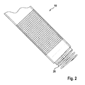
- Fig. 2:
- is a side-elevation view of the embodiment of
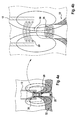
Fig. 1 ; - Figs. 3a and b:
- illustrate the operation of the embodiment of
Figs. 1 and2 ; - Figs. 4a and b:
- disclose an alternative embodiment;
- Figs 5a and b:
- illustrate a further alternative embodiment;
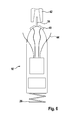
- Fig. 6:
- is a diagrammatic representation of an embodiment of an leadless pacemaker with a fixation element to fix the leadless pacemaker to an implantation tool;
- Figs. 7 and 8:
- disclose an alternative embodiment of a catheter for recharging a battery of an leadless pacemaker;
- In
Fig. 1 , a leadless heart stimulation and/ormonitoring device 10 is placed within a distal end of acatheter 12. In the embodiment offigure 1 , the leadless heart stimulation and/ormonitoring device 10 is a leadless pacemaker. - The heart stimulation and/or monitoring device has a sealed
housing 20 that included a power supply comprising arechargeable battery 22.Battery 22 may be composed of one or more battery cells.Housing 20 further includeselectric components 24 that are operatively connected tobatteries 22. - At a distal end of the heart stimulation and/or
monitoring device 10, ahelical screw 26 is arranged that can be screwed into heart tissue in order to fix the heart stimulation and/or monitoring device to myocardium 16 (heart tissue).Screw 26 thus serves as a first fixation element.Screw 26 may in some embodiments made from electrically conductive material so as to establish an electric contact to the myocardium after implantation and serve as sensing and/or stimulation electrode. -
Batteries 22 are rechargeable. For rechargingbatteries 22, the device's power supply comprises an implant-basedcoil 28 that is dimensioned and arranged so as to receive electric power via an alternating magnetic or electro-magnetic field. Implant-basedcoil 28 is connected tobatteries 22 via a battery charging circuit that is part of theelectric components 24. - The distal end of
catheter 12 is provided with a catheter-basedcoil 30 that can generate and emit an alternating magnetic or electromagnetic field. Implant-basedcoil 28 and catheter-basedcoil 30 are tuned so as to allow an efficient transfer of energy fromcoil 30 tocoil 28. - Catheter-based
coil 30 is electrically connected to an external energy source (not shown) at least when in use. Electric leads (not shown) providing such electric connection are integrated incatheter 12 and allow to supply power to catheter-basedcoil 30. -
Fig. 2 is a side-elevation view of the distal part (tip) ofcatheter 12 andhelical screw 26 of theimplantable leadless pacemaker 10. -
Figs. 3a and 3b illustrate the operation of the embodiment fromFigs. 1 and2 . - According to this embodiment, recharging is achieved by placing the catheter-based
coil 30 over theexternal housing 20 of thedevice 10. The catheter-basedrecharging source coil 30 which resides within the distal end of thecatheter 12 forms a solenoid at the catheter's bore. In another embodiment the coil is embedded in the sidewall of the catheter. This embodiment provides the shortest charging times as it results in the source and receiver coils 30 and 28 aligning co-axially. In this embodiment thecatheter 12 can either exist as a lose fitting architecture that can easily slip over both the implanteddevice 10 and anytissue 32 that has encapsulated it or it could provide a tighter fit in contexts where the in-growth is either managed appropriately or the distal end of the recharging catheter presents a means for cutting through unmanaged in-growth. In the case that in-growth is appropriately managed and a tighter diameter catheter tip is used, the catheter -basedcharging coil 30 could potentially be used to "recapture" the exposed portion of the implant via electromagnetic attraction. - Potential disadvantages of the embodiment of
Figs. 1 to 3 are that it requires a large diameter catheter tip (-22 French corresponding to 7,3mm) to appropriately accommodate the implant (-19 French corresponding to 6,3 mm) and potentially its encapsulatingtissue 32. These restrictions can result in increased complication risks. - It is noted that in
Fig. 3a for purposes of clarity a contoured geometry oftissue 32 within ventricle not explicitly shown. 'Recapturing' the device by the recharging catheter is critical for this embodiment to work properly. With a coil present, the rechargingcatheter 12 can operate as an electromagnet to enable aligning and capturing the implantable device. - In order to keep the outer and thus the inner dimensions of the distal end of
catheter 12 as small as possible and thus close to the outer diameter of the implantable device, recharging according to the embodiment ofFigs. 1 to 3 demands the ability to either: - 1.) Prevent in-growth from covering the receiver coil
- 2.) Have a mechanism at the tip of the catheter to cut through in-growth
or - 3.) Accept that in-growth will occur and conduct recharging processes across the tissue covering.
-
Figs. 4a and 4b illustrate a second embodiment, wherein the recharging catheter 12' presents a smaller diameter (for example, 10 French, that is 3,3mm) and does not fit around the full girth of theimplant housing 20, but instead contains a mechanical capturing element for latching onto asecond fixation element 36 at the proximal end of theimplantable device 10 such that the primary andsecondary coils catheter 12 contains either an inner tool for mechanically grabbing and holding the implant, or a magnetic tool for "recapturing" the device. To achieve the latter, catheter-basedcoil 30 can be employed to serve as an electromagnet for capturing the device magnetically - Similar to
Fig. 3a ),Fig. 4a ) is not explicitly showing contoured geometry of tissue within the ventricle. As in the embodiment ofFigs. 1 to 3 that leverages full-device overlap by the recharging catheter electromagnetic 'recapture' could be employed. - The type of recharging that is illustrated in
Fig. 4 avoids the need to manage or cut through in-growth tissue to interface the implant. Advantageously, a catheter with a smaller diameter catheter tip leading to a less invasive process for delivering recharging can be used compared to the case where the catheter tip fully overlaps theouter housing 20 of theimplant 10. Flux linkage is less robust in this approach compared to full-device overlap but is likely a worthwhile tradeoff considering gains for: - 1.) Avoiding a need to cut-through or manage in-growth and
- 2.) Minimizing the invasiveness of the recharging.
-
Figs. 5a and 5b illustrate yet another embodiment of this invention that would again leverage a smaller diameter recharging catheter (for example, 10 French.). In this configuration, the rechargingcatheter 12 would not need to attach to or surround theimplant 10, but would instead be stationed in near proximity (for example, within the same heart chamber). With such an approach, charging is less efficient than the two previously discussed methods because thecoils - Again, in
Fig. 5a ) contoured geometry of tissue within the ventricle is not explicitly shown (for clarity). 'Recapture' is not essential for this embodiment. It could potentially simplify catheter design as no electro-magnet would be needed or used in the tip. - As can be taken from
Fig. 5b ), device recapture is not used in this embodiment. - In the embodiment shown in
Figure 6 theleadless pacemaker 10 has a first fixation element (helical screw 26) on its distal side to fix theleadless pacemaker 10 to the heart tissue. Thefirst fixation element 26 in this embodiment is ahelical screw 26 that is screwed into theheart tissue 32. In alternative embodiments, other fixation elements are provided that fix alone or in combination the leadless pacemaker in it's implanted position. - The
leadless pacemaker 10 further has asecond fixation element 36 on its proximal side to fix theleadless pacemaker 10 on the implantation tool, which is in this embodiment an introduction catheter but could as well be a recharging catheter. Thesecond fixation element 36 connects the leadless pacemaker to the catheter. According to the embodiment ofFigure 6 , thesecond fixation element 36 may provide at least one, preferably twoelectrical contacts 40 that provide viacorresponding contacts 42 in the catheter a communicative connection between theleadless pacemaker 10 and an external programming device (not shown) for theleadless pacemaker 10. Thesecond fixation element 36 is in one embodiment a substantial flat extension of theproximal device housing 20 havingelectrical contacts 40 that are releasable clamped by the catheter. The clamps of the catheter also haveelectrical contacts 42 that connect to theleadless pacemaker 10 when theleadless pacemaker 10 is clamped by the catheter and provide via wire connection to the external programmer. This system allows for programming theleadless pacemaker 10 during the implantation process without the need of an inductive or radio frequency communication link for programming. - In an alternative embodiment also shown in
Figure 6 the wires in the implantation tool are connected directly to the leadless pacemaker and formed as isolated break awaywires 44 having predetermined breaking points close to the leadless pacemaker. In this embodiment, alternative embodiments of the second fixation elements are possible as described above in the embodiment ofFigures 1 to 3 . This system allows for programming the leadless pacemaker 10' during the implantation process without the need of an inductive or radio frequency communication link for programming. Once the leadless pacemaker 10' is implanted and programmed, thesecond fixation element 36 is released and by moving the catheter used as implantation tool back the wires break at the predetermined breaking points. The force to break the wires is less than the force to fix the implant provided by thefirst fixation element 26. In a further embodiment the remaining parts of the wires are connected to piezo elements that are used for harvesting of electrical energy by their movement to power the leadless pacemaker. - For the embodiment shown in
Figures 1 to 3 the introduction tool is a sheath having an open distal end and an inner lumen that provides the second fixation element to fix the leadless pacemaker on its proximal side for implantation. The first fixation element on the distal side of the leadless pacemaker may be the same as described in the embodiment ofFigure 6 . In embodiment ofFigures 1 to 3 , catheter-basedcoil 30 may serve as a telemetry coil that is imbedded in the introducer (catheter) sheath as shown in detail inFigure 1 and used to communicate and power theleadless pacemaker 10 that resides during implantation and during recharging in the area within the catheter-based coil, which would also have a telemetry coil built axially into it. During implantation the device could be powered through the coil and programmed at the same time. This would require no power of the implants power source to program the device. -
Figs. 7 and 8 show details of an additional embodiment withadditional electrodes 48 for sensing electrical signals of the tissue. Theadditional electrodes 48 are provided on the distal end of the catheter sheath as shown inFigure 7 and Figure 8 . Theelectrodes 48 are electrically connected to the programmer during implantation. - For example during implantation of a leadless pacemaker the catheter is forwarded up to the cardiac tissue and via the
electrodes 48 of the catheter sheath electrical cardiac signals are sensed and displayed on the programmer. The implanting physician can decide whether the position is appropriate for final implantation or not and replace the distal end of the catheter if necessary. Once the final position of for implantation is found the leadless pacemaker located within the catheter sheath is forwarded and fixed, the second fixation element at the distal side of the leadless pacemaker is released and the sheath is removed. - In an alternative embodiment of the second fixation element for fixing the proximal side of the leadless pacemaker an inflatable balloon is located within the catheter sheath near the distal end of the catheter. The leadless pacemaker in this embodiment is formed at its proximal end such that the proximal end of the implant deforms the deflated balloon on introduction into the catheter sheath from the distal end of the sheath but allows the balloon to grip the proximal end of the leadless pacemaker when inflated. In a preferred embodiment the proximal end of the leadless pacemaker, as shown in
figure 1 extends substantial cylindrically to a ball (which is part of the second fixation element 36) with a diameter sufficiently small to deform the deflated balloon such that the balloon, once inflated fixes the leadless pacemaker sufficiently for implantation. - The inductive recharging strategy presented in this disclosure offers a realistic avenue for dramatically extending the functional lifespan of leadless pacemakers. As most pacer designs interface with the myocardium via implant sites internal to the heart, robust anchoring methods prove essential. Device dislodgement in such contexts would knowingly lead to pulmonary embolisms (on the right-side of the heart) and/or stroke (on the left). Unfortunately, this need for robust anchoring combined with device in-growth, implant depth, and the constant contractions and blood flow native to the implant environment, present serious challenges for renewed/continual power support. The electromagnet absorption response of the human body enforces weak coupling for inductive charging sources stationed outside of the body. By directly recharging using a close-proximity catheter our approach cuts recharging times to manageable levels, trading off short-term procedure-affiliated discomforts for dramatic gains in device support and longevity. Compared to efforts that rely upon primary cell chemistries, our approach additionally overcomes periodic device replacement needs, avoiding the complications associated with implant recapture and explantation processes. Last, device feature set minimization can be driven to a reduced extent by power source management and more so via device sizing and heart geometry considerations.
Claims (13)
- Leadless heart stimulation and/or monitoring device having- a sealed housing with a proximal and a distal end,- one or more electrodes configured to electrically contact heart tissue when in use,- electric components arranged within the housing, said electric components at least in part being operationally connected to said at least one electrode, said electric components including a power supply for providing power supply to said electric components,- said power supply including a rechargeable battery- said power supply further comprising a coil that is configured to receive electric power via a tuned alternating magnetic or electro-magnetic field.
- Leadless heart stimulation and/or monitoring device according to claim 1, wherein the device comprises a first fixation element at the distal end to anchor the device in heart tissue.
- Leadless heart stimulation and/or monitoring device according to claim 1 or 2, wherein the electric components comprise a battery recharging circuit that is electrically connected to both, the implant-based coil and the rechargeable battery of the power supply.
- Leadless heart stimulation and/or monitoring device according to one of claims 1 to 3, wherein the housing has a diameter of less than 8 mm.
- Leadless heart stimulation and/or monitoring device according to one of claims 1 to 4, wherein the device comprises a second fixation element that is arranged at a proximal end and configured to be latched by a capturing element of a catheter.
- Leadless heart stimulation and/or monitoring system comprising an device having- a sealed housing,- one or more electrodes configured to electrically contact heart tissue when in use,- electric components arranged within the housing, said electric components at least in part being operationally connected to said at least one electrode, said electric components including a power supply for providing power supply to said electric components,- said power supply including a rechargeable battery- said power supply further comprising an implant-based coil that is configured to receive electric power via a tuned alternating magnetic or electro-magnetic field,
said system further comprising a recharging catheter having a distal end and a catheter-based coil arranged at or near said distal end,
said catheter being dimensioned to be introduced into a heart chamber,
said catheter-based coil being tuned to said implant-based coil. - Leadless heart stimulation and/or monitoring system according to claim 6, wherein the device comprises a first fixation element at the distal end to anchor the device in heart tissue.
- Leadless heart stimulation and/or monitoring system according to claim 6 or 7, wherein the electric components comprise a battery recharging circuit that is electrically connected to both, the implant-based coil and the rechargeable battery of the power supply.
- Leadless heart stimulation and/or monitoring system according to one of claims 6 to 8, wherein the housing has a diameter of less than 8 mm.
- Leadless heart stimulation and/or monitoring system according to one of claims 6 to 9, wherein the device comprises a second fixation element that is arranged at a proximal end and configured to be latched by a capturing element of a catheter.
- Leadless heart stimulation and/or monitoring system according to claim 10, wherein said recharging catheter comprises a capturing element mating said second fixation element.
- Leadless heart stimulation and/or monitoring system according to one of claims 6 to 11, wherein said recharging catheter is dimensioned so that a distal catheter end can slip over the housing of the device.
- Leadless heart stimulation and/or monitoring system according to one of claims 6 to 12, wherein the catheter-based coil is configured to act a an electro-magnet for capturing the device.
Applications Claiming Priority (2)
| Application Number | Priority Date | Filing Date | Title |
|---|---|---|---|
| US201261643912P | 2012-05-08 | 2012-05-08 | |
| US201261643911P | 2012-05-08 | 2012-05-08 |
Publications (3)
| Publication Number | Publication Date |
|---|---|
| EP2662113A2 true EP2662113A2 (en) | 2013-11-13 |
| EP2662113A3 EP2662113A3 (en) | 2014-01-08 |
| EP2662113B1 EP2662113B1 (en) | 2016-08-31 |
Family
ID=48143494
Family Applications (1)
| Application Number | Title | Priority Date | Filing Date |
|---|---|---|---|
| EP13164437.9A Active EP2662113B1 (en) | 2012-05-08 | 2013-04-19 | Leadless heart stimulation and/or monitoring device |
Country Status (2)
| Country | Link |
|---|---|
| US (1) | US20130303872A1 (en) |
| EP (1) | EP2662113B1 (en) |
Cited By (79)
| Publication number | Priority date | Publication date | Assignee | Title |
|---|---|---|---|---|
| US9669230B2 (en) | 2015-02-06 | 2017-06-06 | Cardiac Pacemakers, Inc. | Systems and methods for treating cardiac arrhythmias |
| US9853743B2 (en) | 2015-08-20 | 2017-12-26 | Cardiac Pacemakers, Inc. | Systems and methods for communication between medical devices |
| US9956414B2 (en) | 2015-08-27 | 2018-05-01 | Cardiac Pacemakers, Inc. | Temporal configuration of a motion sensor in an implantable medical device |
| US9968787B2 (en) | 2015-08-27 | 2018-05-15 | Cardiac Pacemakers, Inc. | Spatial configuration of a motion sensor in an implantable medical device |
| US10029107B1 (en) | 2017-01-26 | 2018-07-24 | Cardiac Pacemakers, Inc. | Leadless device with overmolded components |
| US10050700B2 (en) | 2015-03-18 | 2018-08-14 | Cardiac Pacemakers, Inc. | Communications in a medical device system with temporal optimization |
| US10046167B2 (en) | 2015-02-09 | 2018-08-14 | Cardiac Pacemakers, Inc. | Implantable medical device with radiopaque ID tag |
| WO2018134330A3 (en) * | 2017-01-19 | 2018-08-30 | HighDim GmbH | Devices and methods for determining heart function of a living subject |
| US10065041B2 (en) | 2015-10-08 | 2018-09-04 | Cardiac Pacemakers, Inc. | Devices and methods for adjusting pacing rates in an implantable medical device |
| US10092760B2 (en) | 2015-09-11 | 2018-10-09 | Cardiac Pacemakers, Inc. | Arrhythmia detection and confirmation |
| US10137305B2 (en) | 2015-08-28 | 2018-11-27 | Cardiac Pacemakers, Inc. | Systems and methods for behaviorally responsive signal detection and therapy delivery |
| US10159842B2 (en) | 2015-08-28 | 2018-12-25 | Cardiac Pacemakers, Inc. | System and method for detecting tamponade |
| US10183170B2 (en) | 2015-12-17 | 2019-01-22 | Cardiac Pacemakers, Inc. | Conducted communication in a medical device system |
| US10213610B2 (en) | 2015-03-18 | 2019-02-26 | Cardiac Pacemakers, Inc. | Communications in a medical device system with link quality assessment |
| US10220213B2 (en) | 2015-02-06 | 2019-03-05 | Cardiac Pacemakers, Inc. | Systems and methods for safe delivery of electrical stimulation therapy |
| US10226631B2 (en) | 2015-08-28 | 2019-03-12 | Cardiac Pacemakers, Inc. | Systems and methods for infarct detection |
| US10328272B2 (en) | 2016-05-10 | 2019-06-25 | Cardiac Pacemakers, Inc. | Retrievability for implantable medical devices |
| US10350423B2 (en) | 2016-02-04 | 2019-07-16 | Cardiac Pacemakers, Inc. | Delivery system with force sensor for leadless cardiac device |
| US10357159B2 (en) | 2015-08-20 | 2019-07-23 | Cardiac Pacemakers, Inc | Systems and methods for communication between medical devices |
| US10390720B2 (en) | 2014-07-17 | 2019-08-27 | Medtronic, Inc. | Leadless pacing system including sensing extension |
| US10391319B2 (en) | 2016-08-19 | 2019-08-27 | Cardiac Pacemakers, Inc. | Trans septal implantable medical device |
| US10413733B2 (en) | 2016-10-27 | 2019-09-17 | Cardiac Pacemakers, Inc. | Implantable medical device with gyroscope |
| US10426962B2 (en) | 2016-07-07 | 2019-10-01 | Cardiac Pacemakers, Inc. | Leadless pacemaker using pressure measurements for pacing capture verification |
| US10434317B2 (en) | 2016-10-31 | 2019-10-08 | Cardiac Pacemakers, Inc. | Systems and methods for activity level pacing |
| US10434314B2 (en) | 2016-10-27 | 2019-10-08 | Cardiac Pacemakers, Inc. | Use of a separate device in managing the pace pulse energy of a cardiac pacemaker |
| US10463305B2 (en) | 2016-10-27 | 2019-11-05 | Cardiac Pacemakers, Inc. | Multi-device cardiac resynchronization therapy with timing enhancements |
| US10512784B2 (en) | 2016-06-27 | 2019-12-24 | Cardiac Pacemakers, Inc. | Cardiac therapy system using subcutaneously sensed P-waves for resynchronization pacing management |
| US10561330B2 (en) | 2016-10-27 | 2020-02-18 | Cardiac Pacemakers, Inc. | Implantable medical device having a sense channel with performance adjustment |
| US10583303B2 (en) | 2016-01-19 | 2020-03-10 | Cardiac Pacemakers, Inc. | Devices and methods for wirelessly recharging a rechargeable battery of an implantable medical device |
| US10583301B2 (en) | 2016-11-08 | 2020-03-10 | Cardiac Pacemakers, Inc. | Implantable medical device for atrial deployment |
| US10617874B2 (en) | 2016-10-31 | 2020-04-14 | Cardiac Pacemakers, Inc. | Systems and methods for activity level pacing |
| WO2020078655A1 (en) * | 2018-10-17 | 2020-04-23 | Biotronik Se & Co. Kg | Catheter system for explanting an intracardiac pacing system |
| US10632313B2 (en) | 2016-11-09 | 2020-04-28 | Cardiac Pacemakers, Inc. | Systems, devices, and methods for setting cardiac pacing pulse parameters for a cardiac pacing device |
| US10639486B2 (en) | 2016-11-21 | 2020-05-05 | Cardiac Pacemakers, Inc. | Implantable medical device with recharge coil |
| US10668294B2 (en) | 2016-05-10 | 2020-06-02 | Cardiac Pacemakers, Inc. | Leadless cardiac pacemaker configured for over the wire delivery |
| US10688304B2 (en) | 2016-07-20 | 2020-06-23 | Cardiac Pacemakers, Inc. | Method and system for utilizing an atrial contraction timing fiducial in a leadless cardiac pacemaker system |
| US10722720B2 (en) | 2014-01-10 | 2020-07-28 | Cardiac Pacemakers, Inc. | Methods and systems for improved communication between medical devices |
| US10737102B2 (en) | 2017-01-26 | 2020-08-11 | Cardiac Pacemakers, Inc. | Leadless implantable device with detachable fixation |
| US10758724B2 (en) | 2016-10-27 | 2020-09-01 | Cardiac Pacemakers, Inc. | Implantable medical device delivery system with integrated sensor |
| US10758737B2 (en) | 2016-09-21 | 2020-09-01 | Cardiac Pacemakers, Inc. | Using sensor data from an intracardially implanted medical device to influence operation of an extracardially implantable cardioverter |
| US10765871B2 (en) | 2016-10-27 | 2020-09-08 | Cardiac Pacemakers, Inc. | Implantable medical device with pressure sensor |
| US10780278B2 (en) | 2016-08-24 | 2020-09-22 | Cardiac Pacemakers, Inc. | Integrated multi-device cardiac resynchronization therapy using P-wave to pace timing |
| US10821288B2 (en) | 2017-04-03 | 2020-11-03 | Cardiac Pacemakers, Inc. | Cardiac pacemaker with pacing pulse energy adjustment based on sensed heart rate |
| US10835753B2 (en) | 2017-01-26 | 2020-11-17 | Cardiac Pacemakers, Inc. | Intra-body device communication with redundant message transmission |
| US10870008B2 (en) | 2016-08-24 | 2020-12-22 | Cardiac Pacemakers, Inc. | Cardiac resynchronization using fusion promotion for timing management |
| US10874861B2 (en) | 2018-01-04 | 2020-12-29 | Cardiac Pacemakers, Inc. | Dual chamber pacing without beat-to-beat communication |
| US10881863B2 (en) | 2016-11-21 | 2021-01-05 | Cardiac Pacemakers, Inc. | Leadless cardiac pacemaker with multimode communication |
| US10881869B2 (en) | 2016-11-21 | 2021-01-05 | Cardiac Pacemakers, Inc. | Wireless re-charge of an implantable medical device |
| US10894163B2 (en) | 2016-11-21 | 2021-01-19 | Cardiac Pacemakers, Inc. | LCP based predictive timing for cardiac resynchronization |
| US10905872B2 (en) | 2017-04-03 | 2021-02-02 | Cardiac Pacemakers, Inc. | Implantable medical device with a movable electrode biased toward an extended position |
| US10905889B2 (en) | 2016-09-21 | 2021-02-02 | Cardiac Pacemakers, Inc. | Leadless stimulation device with a housing that houses internal components of the leadless stimulation device and functions as the battery case and a terminal of an internal battery |
| US10905886B2 (en) | 2015-12-28 | 2021-02-02 | Cardiac Pacemakers, Inc. | Implantable medical device for deployment across the atrioventricular septum |
| US10918875B2 (en) | 2017-08-18 | 2021-02-16 | Cardiac Pacemakers, Inc. | Implantable medical device with a flux concentrator and a receiving coil disposed about the flux concentrator |
| US10994145B2 (en) | 2016-09-21 | 2021-05-04 | Cardiac Pacemakers, Inc. | Implantable cardiac monitor |
| US11052258B2 (en) | 2017-12-01 | 2021-07-06 | Cardiac Pacemakers, Inc. | Methods and systems for detecting atrial contraction timing fiducials within a search window from a ventricularly implanted leadless cardiac pacemaker |
| US11058880B2 (en) | 2018-03-23 | 2021-07-13 | Medtronic, Inc. | VFA cardiac therapy for tachycardia |
| US11065459B2 (en) | 2017-08-18 | 2021-07-20 | Cardiac Pacemakers, Inc. | Implantable medical device with pressure sensor |
| US11071870B2 (en) | 2017-12-01 | 2021-07-27 | Cardiac Pacemakers, Inc. | Methods and systems for detecting atrial contraction timing fiducials and determining a cardiac interval from a ventricularly implanted leadless cardiac pacemaker |
| US11116988B2 (en) | 2016-03-31 | 2021-09-14 | Cardiac Pacemakers, Inc. | Implantable medical device with rechargeable battery |
| US11185703B2 (en) | 2017-11-07 | 2021-11-30 | Cardiac Pacemakers, Inc. | Leadless cardiac pacemaker for bundle of his pacing |
| US11207532B2 (en) | 2017-01-04 | 2021-12-28 | Cardiac Pacemakers, Inc. | Dynamic sensing updates using postural input in a multiple device cardiac rhythm management system |
| US11207527B2 (en) | 2016-07-06 | 2021-12-28 | Cardiac Pacemakers, Inc. | Method and system for determining an atrial contraction timing fiducial in a leadless cardiac pacemaker system |
| US11213676B2 (en) | 2019-04-01 | 2022-01-04 | Medtronic, Inc. | Delivery systems for VfA cardiac therapy |
| US11235163B2 (en) | 2017-09-20 | 2022-02-01 | Cardiac Pacemakers, Inc. | Implantable medical device with multiple modes of operation |
| US11235159B2 (en) | 2018-03-23 | 2022-02-01 | Medtronic, Inc. | VFA cardiac resynchronization therapy |
| US11235161B2 (en) | 2018-09-26 | 2022-02-01 | Medtronic, Inc. | Capture in ventricle-from-atrium cardiac therapy |
| US11260216B2 (en) | 2017-12-01 | 2022-03-01 | Cardiac Pacemakers, Inc. | Methods and systems for detecting atrial contraction timing fiducials during ventricular filling from a ventricularly implanted leadless cardiac pacemaker |
| US11285326B2 (en) | 2015-03-04 | 2022-03-29 | Cardiac Pacemakers, Inc. | Systems and methods for treating cardiac arrhythmias |
| US11305127B2 (en) | 2019-08-26 | 2022-04-19 | Medtronic Inc. | VfA delivery and implant region detection |
| US11400296B2 (en) | 2018-03-23 | 2022-08-02 | Medtronic, Inc. | AV synchronous VfA cardiac therapy |
| US11529523B2 (en) | 2018-01-04 | 2022-12-20 | Cardiac Pacemakers, Inc. | Handheld bridge device for providing a communication bridge between an implanted medical device and a smartphone |
| US11679265B2 (en) | 2019-02-14 | 2023-06-20 | Medtronic, Inc. | Lead-in-lead systems and methods for cardiac therapy |
| US11697025B2 (en) | 2019-03-29 | 2023-07-11 | Medtronic, Inc. | Cardiac conduction system capture |
| US11712188B2 (en) | 2019-05-07 | 2023-08-01 | Medtronic, Inc. | Posterior left bundle branch engagement |
| US11813464B2 (en) | 2020-07-31 | 2023-11-14 | Medtronic, Inc. | Cardiac conduction system evaluation |
| US11813463B2 (en) | 2017-12-01 | 2023-11-14 | Cardiac Pacemakers, Inc. | Leadless cardiac pacemaker with reversionary behavior |
| US11813466B2 (en) | 2020-01-27 | 2023-11-14 | Medtronic, Inc. | Atrioventricular nodal stimulation |
| US11911168B2 (en) | 2020-04-03 | 2024-02-27 | Medtronic, Inc. | Cardiac conduction system therapy benefit determination |
| US11951313B2 (en) | 2018-11-17 | 2024-04-09 | Medtronic, Inc. | VFA delivery systems and methods |
Families Citing this family (15)
| Publication number | Priority date | Publication date | Assignee | Title |
|---|---|---|---|---|
| AU2015204701B2 (en) | 2014-01-10 | 2018-03-15 | Cardiac Pacemakers, Inc. | Systems and methods for detecting cardiac arrhythmias |
| US9399140B2 (en) | 2014-07-25 | 2016-07-26 | Medtronic, Inc. | Atrial contraction detection by a ventricular leadless pacing device for atrio-synchronous ventricular pacing |
| WO2016033197A2 (en) | 2014-08-28 | 2016-03-03 | Cardiac Pacemakers, Inc. | Medical device with triggered blanking period |
| US9724519B2 (en) | 2014-11-11 | 2017-08-08 | Medtronic, Inc. | Ventricular leadless pacing device mode switching |
| US9492668B2 (en) | 2014-11-11 | 2016-11-15 | Medtronic, Inc. | Mode switching by a ventricular leadless pacing device |
| US9623234B2 (en) | 2014-11-11 | 2017-04-18 | Medtronic, Inc. | Leadless pacing device implantation |
| US9492669B2 (en) | 2014-11-11 | 2016-11-15 | Medtronic, Inc. | Mode switching by a ventricular leadless pacing device |
| US9289612B1 (en) | 2014-12-11 | 2016-03-22 | Medtronic Inc. | Coordination of ventricular pacing in a leadless pacing system |
| US9216285B1 (en) * | 2014-12-18 | 2015-12-22 | Pacesetter, Inc. | Leadless implantable medical device having removable and fixed components |
| US9808618B2 (en) | 2015-04-23 | 2017-11-07 | Medtronic, Inc. | Dual chamber intracardiac medical device |
| WO2016172625A1 (en) | 2015-04-23 | 2016-10-27 | Medtronic, Inc. | Intracardiac medical device |
| EP3436138B1 (en) * | 2016-03-31 | 2020-01-29 | Cardiac Pacemakers, Inc. | Chronically implantable medical devices configured for extraction and extraction devices for extracting chronically implanted medical devices |
| JP2019509847A (en) | 2016-03-31 | 2019-04-11 | カーディアック ペースメイカーズ, インコーポレイテッド | Extraction device configured to extract medical devices implanted in the long term |
| CN109996585B (en) | 2016-11-21 | 2023-06-13 | 心脏起搏器股份公司 | Implantable medical device with magnetically permeable housing and induction coil disposed around the housing |
| FR3121606A1 (en) | 2021-04-13 | 2022-10-14 | Laurent Berneman | Electrical stimulation device having an optimized means of energy harvesting |
Family Cites Families (16)
| Publication number | Priority date | Publication date | Assignee | Title |
|---|---|---|---|---|
| US4886065A (en) * | 1988-08-08 | 1989-12-12 | California Institute Of Technology | In vivo electrode implanting system |
| US5348553A (en) * | 1991-12-18 | 1994-09-20 | Whitney Douglass G | Method for promoting blood vessel healing |
| US6409674B1 (en) * | 1998-09-24 | 2002-06-25 | Data Sciences International, Inc. | Implantable sensor with wireless communication |
| WO2002007794A2 (en) * | 2000-07-24 | 2002-01-31 | Stereotaxis, Inc. | Magnetically navigated pacing leads, and methods for delivering medical devices |
| US6783499B2 (en) * | 2000-12-18 | 2004-08-31 | Biosense, Inc. | Anchoring mechanism for implantable telemetric medical sensor |
| ATE364348T1 (en) * | 2003-06-17 | 2007-07-15 | Raymond Moser | IMPLANTABLE AND RETRACTABLE SENSOR DEVICE |
| US9498366B2 (en) * | 2003-07-28 | 2016-11-22 | Baronova, Inc. | Devices and methods for pyloric anchoring |
| US20050267555A1 (en) * | 2004-05-28 | 2005-12-01 | Marnfeldt Goran N | Engagement tool for implantable medical devices |
| EP1812104B1 (en) * | 2004-10-20 | 2012-11-21 | Boston Scientific Limited | Leadless cardiac stimulation systems |
| US8818504B2 (en) * | 2004-12-16 | 2014-08-26 | Cardiac Pacemakers Inc | Leadless cardiac stimulation device employing distributed logic |
| US7621036B2 (en) * | 2005-06-21 | 2009-11-24 | Cardiomems, Inc. | Method of manufacturing implantable wireless sensor for in vivo pressure measurement |
| US8644934B2 (en) * | 2006-09-13 | 2014-02-04 | Boston Scientific Scimed Inc. | Cardiac stimulation using leadless electrode assemblies |
| US8676349B2 (en) * | 2006-09-15 | 2014-03-18 | Cardiac Pacemakers, Inc. | Mechanism for releasably engaging an implantable medical device for implantation |
| US20120059389A1 (en) * | 2009-02-20 | 2012-03-08 | Loren Robert Larson | Implantable Micro-Generator Devices with Optimized Configuration, Methods of Use, Systems and Kits Therefor |
| US8983619B2 (en) * | 2009-12-30 | 2015-03-17 | Medtronic, Inc. | Testing communication during implantation |
| US20120095539A1 (en) * | 2010-10-13 | 2012-04-19 | Alexander Khairkhahan | Delivery Catheter Systems and Methods |
-
2013
- 2013-04-19 EP EP13164437.9A patent/EP2662113B1/en active Active
- 2013-05-08 US US13/890,181 patent/US20130303872A1/en not_active Abandoned
Non-Patent Citations (1)
| Title |
|---|
| None |
Cited By (97)
| Publication number | Priority date | Publication date | Assignee | Title |
|---|---|---|---|---|
| US10722720B2 (en) | 2014-01-10 | 2020-07-28 | Cardiac Pacemakers, Inc. | Methods and systems for improved communication between medical devices |
| US10674928B2 (en) | 2014-07-17 | 2020-06-09 | Medtronic, Inc. | Leadless pacing system including sensing extension |
| US10390720B2 (en) | 2014-07-17 | 2019-08-27 | Medtronic, Inc. | Leadless pacing system including sensing extension |
| US9669230B2 (en) | 2015-02-06 | 2017-06-06 | Cardiac Pacemakers, Inc. | Systems and methods for treating cardiac arrhythmias |
| US11020595B2 (en) | 2015-02-06 | 2021-06-01 | Cardiac Pacemakers, Inc. | Systems and methods for treating cardiac arrhythmias |
| US10238882B2 (en) | 2015-02-06 | 2019-03-26 | Cardiac Pacemakers | Systems and methods for treating cardiac arrhythmias |
| US11224751B2 (en) | 2015-02-06 | 2022-01-18 | Cardiac Pacemakers, Inc. | Systems and methods for safe delivery of electrical stimulation therapy |
| US10220213B2 (en) | 2015-02-06 | 2019-03-05 | Cardiac Pacemakers, Inc. | Systems and methods for safe delivery of electrical stimulation therapy |
| US11020600B2 (en) | 2015-02-09 | 2021-06-01 | Cardiac Pacemakers, Inc. | Implantable medical device with radiopaque ID tag |
| US10046167B2 (en) | 2015-02-09 | 2018-08-14 | Cardiac Pacemakers, Inc. | Implantable medical device with radiopaque ID tag |
| US11285326B2 (en) | 2015-03-04 | 2022-03-29 | Cardiac Pacemakers, Inc. | Systems and methods for treating cardiac arrhythmias |
| US10946202B2 (en) | 2015-03-18 | 2021-03-16 | Cardiac Pacemakers, Inc. | Communications in a medical device system with link quality assessment |
| US10213610B2 (en) | 2015-03-18 | 2019-02-26 | Cardiac Pacemakers, Inc. | Communications in a medical device system with link quality assessment |
| US11476927B2 (en) | 2015-03-18 | 2022-10-18 | Cardiac Pacemakers, Inc. | Communications in a medical device system with temporal optimization |
| US10050700B2 (en) | 2015-03-18 | 2018-08-14 | Cardiac Pacemakers, Inc. | Communications in a medical device system with temporal optimization |
| US9853743B2 (en) | 2015-08-20 | 2017-12-26 | Cardiac Pacemakers, Inc. | Systems and methods for communication between medical devices |
| US10357159B2 (en) | 2015-08-20 | 2019-07-23 | Cardiac Pacemakers, Inc | Systems and methods for communication between medical devices |
| US10709892B2 (en) | 2015-08-27 | 2020-07-14 | Cardiac Pacemakers, Inc. | Temporal configuration of a motion sensor in an implantable medical device |
| US9968787B2 (en) | 2015-08-27 | 2018-05-15 | Cardiac Pacemakers, Inc. | Spatial configuration of a motion sensor in an implantable medical device |
| US9956414B2 (en) | 2015-08-27 | 2018-05-01 | Cardiac Pacemakers, Inc. | Temporal configuration of a motion sensor in an implantable medical device |
| US10137305B2 (en) | 2015-08-28 | 2018-11-27 | Cardiac Pacemakers, Inc. | Systems and methods for behaviorally responsive signal detection and therapy delivery |
| US10159842B2 (en) | 2015-08-28 | 2018-12-25 | Cardiac Pacemakers, Inc. | System and method for detecting tamponade |
| US10589101B2 (en) | 2015-08-28 | 2020-03-17 | Cardiac Pacemakers, Inc. | System and method for detecting tamponade |
| US10226631B2 (en) | 2015-08-28 | 2019-03-12 | Cardiac Pacemakers, Inc. | Systems and methods for infarct detection |
| US10092760B2 (en) | 2015-09-11 | 2018-10-09 | Cardiac Pacemakers, Inc. | Arrhythmia detection and confirmation |
| US10065041B2 (en) | 2015-10-08 | 2018-09-04 | Cardiac Pacemakers, Inc. | Devices and methods for adjusting pacing rates in an implantable medical device |
| US10933245B2 (en) | 2015-12-17 | 2021-03-02 | Cardiac Pacemakers, Inc. | Conducted communication in a medical device system |
| US10183170B2 (en) | 2015-12-17 | 2019-01-22 | Cardiac Pacemakers, Inc. | Conducted communication in a medical device system |
| US10905886B2 (en) | 2015-12-28 | 2021-02-02 | Cardiac Pacemakers, Inc. | Implantable medical device for deployment across the atrioventricular septum |
| US10583303B2 (en) | 2016-01-19 | 2020-03-10 | Cardiac Pacemakers, Inc. | Devices and methods for wirelessly recharging a rechargeable battery of an implantable medical device |
| US10350423B2 (en) | 2016-02-04 | 2019-07-16 | Cardiac Pacemakers, Inc. | Delivery system with force sensor for leadless cardiac device |
| US11116988B2 (en) | 2016-03-31 | 2021-09-14 | Cardiac Pacemakers, Inc. | Implantable medical device with rechargeable battery |
| US10328272B2 (en) | 2016-05-10 | 2019-06-25 | Cardiac Pacemakers, Inc. | Retrievability for implantable medical devices |
| US10668294B2 (en) | 2016-05-10 | 2020-06-02 | Cardiac Pacemakers, Inc. | Leadless cardiac pacemaker configured for over the wire delivery |
| US10512784B2 (en) | 2016-06-27 | 2019-12-24 | Cardiac Pacemakers, Inc. | Cardiac therapy system using subcutaneously sensed P-waves for resynchronization pacing management |
| US11497921B2 (en) | 2016-06-27 | 2022-11-15 | Cardiac Pacemakers, Inc. | Cardiac therapy system using subcutaneously sensed p-waves for resynchronization pacing management |
| US11207527B2 (en) | 2016-07-06 | 2021-12-28 | Cardiac Pacemakers, Inc. | Method and system for determining an atrial contraction timing fiducial in a leadless cardiac pacemaker system |
| US10426962B2 (en) | 2016-07-07 | 2019-10-01 | Cardiac Pacemakers, Inc. | Leadless pacemaker using pressure measurements for pacing capture verification |
| US10688304B2 (en) | 2016-07-20 | 2020-06-23 | Cardiac Pacemakers, Inc. | Method and system for utilizing an atrial contraction timing fiducial in a leadless cardiac pacemaker system |
| US10391319B2 (en) | 2016-08-19 | 2019-08-27 | Cardiac Pacemakers, Inc. | Trans septal implantable medical device |
| US11464982B2 (en) | 2016-08-24 | 2022-10-11 | Cardiac Pacemakers, Inc. | Integrated multi-device cardiac resynchronization therapy using p-wave to pace timing |
| US10780278B2 (en) | 2016-08-24 | 2020-09-22 | Cardiac Pacemakers, Inc. | Integrated multi-device cardiac resynchronization therapy using P-wave to pace timing |
| US10870008B2 (en) | 2016-08-24 | 2020-12-22 | Cardiac Pacemakers, Inc. | Cardiac resynchronization using fusion promotion for timing management |
| US10758737B2 (en) | 2016-09-21 | 2020-09-01 | Cardiac Pacemakers, Inc. | Using sensor data from an intracardially implanted medical device to influence operation of an extracardially implantable cardioverter |
| US10994145B2 (en) | 2016-09-21 | 2021-05-04 | Cardiac Pacemakers, Inc. | Implantable cardiac monitor |
| US10905889B2 (en) | 2016-09-21 | 2021-02-02 | Cardiac Pacemakers, Inc. | Leadless stimulation device with a housing that houses internal components of the leadless stimulation device and functions as the battery case and a terminal of an internal battery |
| US11305125B2 (en) | 2016-10-27 | 2022-04-19 | Cardiac Pacemakers, Inc. | Implantable medical device with gyroscope |
| US10413733B2 (en) | 2016-10-27 | 2019-09-17 | Cardiac Pacemakers, Inc. | Implantable medical device with gyroscope |
| US10758724B2 (en) | 2016-10-27 | 2020-09-01 | Cardiac Pacemakers, Inc. | Implantable medical device delivery system with integrated sensor |
| US10765871B2 (en) | 2016-10-27 | 2020-09-08 | Cardiac Pacemakers, Inc. | Implantable medical device with pressure sensor |
| US10434314B2 (en) | 2016-10-27 | 2019-10-08 | Cardiac Pacemakers, Inc. | Use of a separate device in managing the pace pulse energy of a cardiac pacemaker |
| US10463305B2 (en) | 2016-10-27 | 2019-11-05 | Cardiac Pacemakers, Inc. | Multi-device cardiac resynchronization therapy with timing enhancements |
| US10561330B2 (en) | 2016-10-27 | 2020-02-18 | Cardiac Pacemakers, Inc. | Implantable medical device having a sense channel with performance adjustment |
| US10617874B2 (en) | 2016-10-31 | 2020-04-14 | Cardiac Pacemakers, Inc. | Systems and methods for activity level pacing |
| US10434317B2 (en) | 2016-10-31 | 2019-10-08 | Cardiac Pacemakers, Inc. | Systems and methods for activity level pacing |
| US10583301B2 (en) | 2016-11-08 | 2020-03-10 | Cardiac Pacemakers, Inc. | Implantable medical device for atrial deployment |
| US10632313B2 (en) | 2016-11-09 | 2020-04-28 | Cardiac Pacemakers, Inc. | Systems, devices, and methods for setting cardiac pacing pulse parameters for a cardiac pacing device |
| US10894163B2 (en) | 2016-11-21 | 2021-01-19 | Cardiac Pacemakers, Inc. | LCP based predictive timing for cardiac resynchronization |
| US10881869B2 (en) | 2016-11-21 | 2021-01-05 | Cardiac Pacemakers, Inc. | Wireless re-charge of an implantable medical device |
| US10881863B2 (en) | 2016-11-21 | 2021-01-05 | Cardiac Pacemakers, Inc. | Leadless cardiac pacemaker with multimode communication |
| US10639486B2 (en) | 2016-11-21 | 2020-05-05 | Cardiac Pacemakers, Inc. | Implantable medical device with recharge coil |
| US11207532B2 (en) | 2017-01-04 | 2021-12-28 | Cardiac Pacemakers, Inc. | Dynamic sensing updates using postural input in a multiple device cardiac rhythm management system |
| CN110545717A (en) * | 2017-01-19 | 2019-12-06 | 海迪有限公司 | Device and method for determining a cardiac function of a living subject |
| US11389640B2 (en) | 2017-01-19 | 2022-07-19 | HighDim GmbH | Devices and methods for determining heart function of a living subject |
| WO2018134330A3 (en) * | 2017-01-19 | 2018-08-30 | HighDim GmbH | Devices and methods for determining heart function of a living subject |
| CN110545717B (en) * | 2017-01-19 | 2023-08-04 | 海迪有限公司 | Apparatus and method for determining cardiac function of living body |
| US10835753B2 (en) | 2017-01-26 | 2020-11-17 | Cardiac Pacemakers, Inc. | Intra-body device communication with redundant message transmission |
| US10029107B1 (en) | 2017-01-26 | 2018-07-24 | Cardiac Pacemakers, Inc. | Leadless device with overmolded components |
| US11590353B2 (en) | 2017-01-26 | 2023-02-28 | Cardiac Pacemakers, Inc. | Intra-body device communication with redundant message transmission |
| US10737102B2 (en) | 2017-01-26 | 2020-08-11 | Cardiac Pacemakers, Inc. | Leadless implantable device with detachable fixation |
| US10821288B2 (en) | 2017-04-03 | 2020-11-03 | Cardiac Pacemakers, Inc. | Cardiac pacemaker with pacing pulse energy adjustment based on sensed heart rate |
| US10905872B2 (en) | 2017-04-03 | 2021-02-02 | Cardiac Pacemakers, Inc. | Implantable medical device with a movable electrode biased toward an extended position |
| US10918875B2 (en) | 2017-08-18 | 2021-02-16 | Cardiac Pacemakers, Inc. | Implantable medical device with a flux concentrator and a receiving coil disposed about the flux concentrator |
| US11065459B2 (en) | 2017-08-18 | 2021-07-20 | Cardiac Pacemakers, Inc. | Implantable medical device with pressure sensor |
| US11235163B2 (en) | 2017-09-20 | 2022-02-01 | Cardiac Pacemakers, Inc. | Implantable medical device with multiple modes of operation |
| US11185703B2 (en) | 2017-11-07 | 2021-11-30 | Cardiac Pacemakers, Inc. | Leadless cardiac pacemaker for bundle of his pacing |
| US11813463B2 (en) | 2017-12-01 | 2023-11-14 | Cardiac Pacemakers, Inc. | Leadless cardiac pacemaker with reversionary behavior |
| US11260216B2 (en) | 2017-12-01 | 2022-03-01 | Cardiac Pacemakers, Inc. | Methods and systems for detecting atrial contraction timing fiducials during ventricular filling from a ventricularly implanted leadless cardiac pacemaker |
| US11052258B2 (en) | 2017-12-01 | 2021-07-06 | Cardiac Pacemakers, Inc. | Methods and systems for detecting atrial contraction timing fiducials within a search window from a ventricularly implanted leadless cardiac pacemaker |
| US11071870B2 (en) | 2017-12-01 | 2021-07-27 | Cardiac Pacemakers, Inc. | Methods and systems for detecting atrial contraction timing fiducials and determining a cardiac interval from a ventricularly implanted leadless cardiac pacemaker |
| US11529523B2 (en) | 2018-01-04 | 2022-12-20 | Cardiac Pacemakers, Inc. | Handheld bridge device for providing a communication bridge between an implanted medical device and a smartphone |
| US10874861B2 (en) | 2018-01-04 | 2020-12-29 | Cardiac Pacemakers, Inc. | Dual chamber pacing without beat-to-beat communication |
| US11400296B2 (en) | 2018-03-23 | 2022-08-02 | Medtronic, Inc. | AV synchronous VfA cardiac therapy |
| US11058880B2 (en) | 2018-03-23 | 2021-07-13 | Medtronic, Inc. | VFA cardiac therapy for tachycardia |
| US11819699B2 (en) | 2018-03-23 | 2023-11-21 | Medtronic, Inc. | VfA cardiac resynchronization therapy |
| US11235159B2 (en) | 2018-03-23 | 2022-02-01 | Medtronic, Inc. | VFA cardiac resynchronization therapy |
| US11235161B2 (en) | 2018-09-26 | 2022-02-01 | Medtronic, Inc. | Capture in ventricle-from-atrium cardiac therapy |
| WO2020078655A1 (en) * | 2018-10-17 | 2020-04-23 | Biotronik Se & Co. Kg | Catheter system for explanting an intracardiac pacing system |
| US11951313B2 (en) | 2018-11-17 | 2024-04-09 | Medtronic, Inc. | VFA delivery systems and methods |
| US11679265B2 (en) | 2019-02-14 | 2023-06-20 | Medtronic, Inc. | Lead-in-lead systems and methods for cardiac therapy |
| US11697025B2 (en) | 2019-03-29 | 2023-07-11 | Medtronic, Inc. | Cardiac conduction system capture |
| US11213676B2 (en) | 2019-04-01 | 2022-01-04 | Medtronic, Inc. | Delivery systems for VfA cardiac therapy |
| US11712188B2 (en) | 2019-05-07 | 2023-08-01 | Medtronic, Inc. | Posterior left bundle branch engagement |
| US11305127B2 (en) | 2019-08-26 | 2022-04-19 | Medtronic Inc. | VfA delivery and implant region detection |
| US11813466B2 (en) | 2020-01-27 | 2023-11-14 | Medtronic, Inc. | Atrioventricular nodal stimulation |
| US11911168B2 (en) | 2020-04-03 | 2024-02-27 | Medtronic, Inc. | Cardiac conduction system therapy benefit determination |
| US11813464B2 (en) | 2020-07-31 | 2023-11-14 | Medtronic, Inc. | Cardiac conduction system evaluation |
Also Published As
| Publication number | Publication date |
|---|---|
| EP2662113A3 (en) | 2014-01-08 |
| US20130303872A1 (en) | 2013-11-14 |
| EP2662113B1 (en) | 2016-08-31 |
Similar Documents
| Publication | Publication Date | Title |
|---|---|---|
| EP2662113B1 (en) | Leadless heart stimulation and/or monitoring device | |
| US7729758B2 (en) | Magnetically coupled microstimulators | |
| US11679257B2 (en) | Method of treating an overactive bladder condition | |
| AU2007313116B2 (en) | Orientation-independent implantable pulse generator | |
| ES2426255T3 (en) | Microstimulator that has a built-in power source and a two-way telemetry system | |
| US7962211B2 (en) | Antenna for an external power source for an implantable medical device, system and method | |
| EP1166820B1 (en) | Implantable medical device with external recharging coil | |
| US6505077B1 (en) | Implantable medical device with external recharging coil electrical connection | |
| US7308316B2 (en) | Storable implantable medical device assembly allowing in package charging | |
| EP3325091B1 (en) | Focused power transfer for implantable medical device | |
| US11844952B2 (en) | System for wirelessly coupling in vivo | |
| US10994147B2 (en) | Implantable medical device structures | |
| WO2006010013A1 (en) | Systems and methods for using a butterfly coil to communicate with or transfer power to an implantable medical device | |
| US20190290911A1 (en) | Implantable medical device structures including recharge and/or telemetry coil | |
| US20170173345A1 (en) | Multi-Tiered Wireless Powering System for Long-Term Implantable Medical Devices | |
| CN109996585A (en) | The implantable medical device of induction coil with magnetic conduction casing and around shell setting | |
| WO2007126454A2 (en) | System for transcutaneous energy transfer to an implantable medical device with mating elements | |
| JP7250904B2 (en) | modular implantable medical device | |
| EP2944352A1 (en) | Inner packaging for a sterilizable container and sterilizable container |
Legal Events
| Date | Code | Title | Description |
|---|---|---|---|
| PUAI | Public reference made under article 153(3) epc to a published international application that has entered the european phase |
Free format text: ORIGINAL CODE: 0009012 |
|
| AK | Designated contracting states |
Kind code of ref document: A2 Designated state(s): AL AT BE BG CH CY CZ DE DK EE ES FI FR GB GR HR HU IE IS IT LI LT LU LV MC MK MT NL NO PL PT RO RS SE SI SK SM TR |
|
| AX | Request for extension of the european patent |
Extension state: BA ME |
|
| PUAL | Search report despatched |
Free format text: ORIGINAL CODE: 0009013 |
|
| AK | Designated contracting states |
Kind code of ref document: A3 Designated state(s): AL AT BE BG CH CY CZ DE DK EE ES FI FR GB GR HR HU IE IS IT LI LT LU LV MC MK MT NL NO PL PT RO RS SE SI SK SM TR |
|
| AX | Request for extension of the european patent |
Extension state: BA ME |
|
| RIC1 | Information provided on ipc code assigned before grant |
Ipc: A61N 1/372 20060101ALI20131203BHEP Ipc: A61B 5/00 20060101ALI20131203BHEP Ipc: A61M 25/00 20060101ALI20131203BHEP Ipc: A61B 5/042 20060101ALI20131203BHEP Ipc: A61N 1/362 20060101ALI20131203BHEP Ipc: A61N 1/378 20060101AFI20131203BHEP |
|
| RIN1 | Information on inventor provided before grant (corrected) |
Inventor name: KLEIN, HAROLD Inventor name: VON ARX, JEFFREY Inventor name: SMITH, KERRY Inventor name: MUESSIG, DIRK Inventor name: TAFF, BRIAN Inventor name: WHITTINGTON, R. HOLLIS Inventor name: KRAETSCHMER, HANNES Inventor name: MOULDER, J. CHRISTOPHER |
|
| 17P | Request for examination filed |
Effective date: 20140527 |
|
| RBV | Designated contracting states (corrected) |
Designated state(s): AL AT BE BG CH CY CZ DE DK EE ES FI FR GB GR HR HU IE IS IT LI LT LU LV MC MK MT NL NO PL PT RO RS SE SI SK SM TR |
|
| RIN1 | Information on inventor provided before grant (corrected) |
Inventor name: MUESSIG, DIRK Inventor name: TAFF, BRIAN Inventor name: KRAETSCHMER, HANNES Inventor name: KLEIN, HAROLD Inventor name: SMITH, KERRY Inventor name: MOULDER, J. CHRISTOPHER Inventor name: WHITTINGTON, R. HOLLIS Inventor name: VON ARX, JEFFREY |
|
| GRAP | Despatch of communication of intention to grant a patent |
Free format text: ORIGINAL CODE: EPIDOSNIGR1 |
|
| INTG | Intention to grant announced |
Effective date: 20160527 |
|
| GRAS | Grant fee paid |
Free format text: ORIGINAL CODE: EPIDOSNIGR3 |
|
| GRAA | (expected) grant |
Free format text: ORIGINAL CODE: 0009210 |
|
| AK | Designated contracting states |
Kind code of ref document: B1 Designated state(s): AL AT BE BG CH CY CZ DE DK EE ES FI FR GB GR HR HU IE IS IT LI LT LU LV MC MK MT NL NO PL PT RO RS SE SI SK SM TR |
|
| REG | Reference to a national code |
Ref country code: CH Ref legal event code: EP Ref country code: GB Ref legal event code: FG4D |
|
| REG | Reference to a national code |
Ref country code: IE Ref legal event code: FG4D |
|
| REG | Reference to a national code |
Ref country code: DE Ref legal event code: R096 Ref document number: 602013010831 Country of ref document: DE |
|
| REG | Reference to a national code |
Ref country code: AT Ref legal event code: REF Ref document number: 824466 Country of ref document: AT Kind code of ref document: T Effective date: 20161015 |
|
| REG | Reference to a national code |
Ref country code: LT Ref legal event code: MG4D |
|
| REG | Reference to a national code |
Ref country code: NL Ref legal event code: MP Effective date: 20160831 |
|
| REG | Reference to a national code |
Ref country code: AT Ref legal event code: MK05 Ref document number: 824466 Country of ref document: AT Kind code of ref document: T Effective date: 20160831 |
|
| PG25 | Lapsed in a contracting state [announced via postgrant information from national office to epo] |
Ref country code: FI Free format text: LAPSE BECAUSE OF FAILURE TO SUBMIT A TRANSLATION OF THE DESCRIPTION OR TO PAY THE FEE WITHIN THE PRESCRIBED TIME-LIMIT Effective date: 20160831 Ref country code: NO Free format text: LAPSE BECAUSE OF FAILURE TO SUBMIT A TRANSLATION OF THE DESCRIPTION OR TO PAY THE FEE WITHIN THE PRESCRIBED TIME-LIMIT Effective date: 20161130 Ref country code: HR Free format text: LAPSE BECAUSE OF FAILURE TO SUBMIT A TRANSLATION OF THE DESCRIPTION OR TO PAY THE FEE WITHIN THE PRESCRIBED TIME-LIMIT Effective date: 20160831 Ref country code: LT Free format text: LAPSE BECAUSE OF FAILURE TO SUBMIT A TRANSLATION OF THE DESCRIPTION OR TO PAY THE FEE WITHIN THE PRESCRIBED TIME-LIMIT Effective date: 20160831 Ref country code: RS Free format text: LAPSE BECAUSE OF FAILURE TO SUBMIT A TRANSLATION OF THE DESCRIPTION OR TO PAY THE FEE WITHIN THE PRESCRIBED TIME-LIMIT Effective date: 20160831 |
|
| PG25 | Lapsed in a contracting state [announced via postgrant information from national office to epo] |
Ref country code: LV Free format text: LAPSE BECAUSE OF FAILURE TO SUBMIT A TRANSLATION OF THE DESCRIPTION OR TO PAY THE FEE WITHIN THE PRESCRIBED TIME-LIMIT Effective date: 20160831 Ref country code: SE Free format text: LAPSE BECAUSE OF FAILURE TO SUBMIT A TRANSLATION OF THE DESCRIPTION OR TO PAY THE FEE WITHIN THE PRESCRIBED TIME-LIMIT Effective date: 20160831 Ref country code: ES Free format text: LAPSE BECAUSE OF FAILURE TO SUBMIT A TRANSLATION OF THE DESCRIPTION OR TO PAY THE FEE WITHIN THE PRESCRIBED TIME-LIMIT Effective date: 20160831 Ref country code: GR Free format text: LAPSE BECAUSE OF FAILURE TO SUBMIT A TRANSLATION OF THE DESCRIPTION OR TO PAY THE FEE WITHIN THE PRESCRIBED TIME-LIMIT Effective date: 20161201 Ref country code: NL Free format text: LAPSE BECAUSE OF FAILURE TO SUBMIT A TRANSLATION OF THE DESCRIPTION OR TO PAY THE FEE WITHIN THE PRESCRIBED TIME-LIMIT Effective date: 20160831 Ref country code: AT Free format text: LAPSE BECAUSE OF FAILURE TO SUBMIT A TRANSLATION OF THE DESCRIPTION OR TO PAY THE FEE WITHIN THE PRESCRIBED TIME-LIMIT Effective date: 20160831 |
|
| PG25 | Lapsed in a contracting state [announced via postgrant information from national office to epo] |
Ref country code: RO Free format text: LAPSE BECAUSE OF FAILURE TO SUBMIT A TRANSLATION OF THE DESCRIPTION OR TO PAY THE FEE WITHIN THE PRESCRIBED TIME-LIMIT Effective date: 20160831 Ref country code: EE Free format text: LAPSE BECAUSE OF FAILURE TO SUBMIT A TRANSLATION OF THE DESCRIPTION OR TO PAY THE FEE WITHIN THE PRESCRIBED TIME-LIMIT Effective date: 20160831 |
|
| PG25 | Lapsed in a contracting state [announced via postgrant information from national office to epo] |
Ref country code: PL Free format text: LAPSE BECAUSE OF FAILURE TO SUBMIT A TRANSLATION OF THE DESCRIPTION OR TO PAY THE FEE WITHIN THE PRESCRIBED TIME-LIMIT Effective date: 20160831 Ref country code: SM Free format text: LAPSE BECAUSE OF FAILURE TO SUBMIT A TRANSLATION OF THE DESCRIPTION OR TO PAY THE FEE WITHIN THE PRESCRIBED TIME-LIMIT Effective date: 20160831 Ref country code: BG Free format text: LAPSE BECAUSE OF FAILURE TO SUBMIT A TRANSLATION OF THE DESCRIPTION OR TO PAY THE FEE WITHIN THE PRESCRIBED TIME-LIMIT Effective date: 20161130 Ref country code: SK Free format text: LAPSE BECAUSE OF FAILURE TO SUBMIT A TRANSLATION OF THE DESCRIPTION OR TO PAY THE FEE WITHIN THE PRESCRIBED TIME-LIMIT Effective date: 20160831 Ref country code: PT Free format text: LAPSE BECAUSE OF FAILURE TO SUBMIT A TRANSLATION OF THE DESCRIPTION OR TO PAY THE FEE WITHIN THE PRESCRIBED TIME-LIMIT Effective date: 20170102 Ref country code: BE Free format text: LAPSE BECAUSE OF FAILURE TO SUBMIT A TRANSLATION OF THE DESCRIPTION OR TO PAY THE FEE WITHIN THE PRESCRIBED TIME-LIMIT Effective date: 20160831 Ref country code: CZ Free format text: LAPSE BECAUSE OF FAILURE TO SUBMIT A TRANSLATION OF THE DESCRIPTION OR TO PAY THE FEE WITHIN THE PRESCRIBED TIME-LIMIT Effective date: 20160831 Ref country code: DK Free format text: LAPSE BECAUSE OF FAILURE TO SUBMIT A TRANSLATION OF THE DESCRIPTION OR TO PAY THE FEE WITHIN THE PRESCRIBED TIME-LIMIT Effective date: 20160831 |
|
| REG | Reference to a national code |
Ref country code: DE Ref legal event code: R097 Ref document number: 602013010831 Country of ref document: DE |
|
| PG25 | Lapsed in a contracting state [announced via postgrant information from national office to epo] |
Ref country code: IT Free format text: LAPSE BECAUSE OF FAILURE TO SUBMIT A TRANSLATION OF THE DESCRIPTION OR TO PAY THE FEE WITHIN THE PRESCRIBED TIME-LIMIT Effective date: 20160831 |
|
| PLBE | No opposition filed within time limit |
Free format text: ORIGINAL CODE: 0009261 |
|
| STAA | Information on the status of an ep patent application or granted ep patent |
Free format text: STATUS: NO OPPOSITION FILED WITHIN TIME LIMIT |
|
| 26N | No opposition filed |
Effective date: 20170601 |
|
| PG25 | Lapsed in a contracting state [announced via postgrant information from national office to epo] |
Ref country code: SI Free format text: LAPSE BECAUSE OF FAILURE TO SUBMIT A TRANSLATION OF THE DESCRIPTION OR TO PAY THE FEE WITHIN THE PRESCRIBED TIME-LIMIT Effective date: 20160831 |
|
| GBPC | Gb: european patent ceased through non-payment of renewal fee |
Effective date: 20170419 |
|
| REG | Reference to a national code |
Ref country code: FR Ref legal event code: ST Effective date: 20171229 |
|
| PG25 | Lapsed in a contracting state [announced via postgrant information from national office to epo] |
Ref country code: MC Free format text: LAPSE BECAUSE OF FAILURE TO SUBMIT A TRANSLATION OF THE DESCRIPTION OR TO PAY THE FEE WITHIN THE PRESCRIBED TIME-LIMIT Effective date: 20160831 Ref country code: FR Free format text: LAPSE BECAUSE OF NON-PAYMENT OF DUE FEES Effective date: 20170502 |
|
| PG25 | Lapsed in a contracting state [announced via postgrant information from national office to epo] |
Ref country code: LU Free format text: LAPSE BECAUSE OF NON-PAYMENT OF DUE FEES Effective date: 20170419 Ref country code: GB Free format text: LAPSE BECAUSE OF NON-PAYMENT OF DUE FEES Effective date: 20170419 |
|
| PG25 | Lapsed in a contracting state [announced via postgrant information from national office to epo] |
Ref country code: MT Free format text: LAPSE BECAUSE OF NON-PAYMENT OF DUE FEES Effective date: 20170419 |
|
| PG25 | Lapsed in a contracting state [announced via postgrant information from national office to epo] |
Ref country code: AL Free format text: LAPSE BECAUSE OF FAILURE TO SUBMIT A TRANSLATION OF THE DESCRIPTION OR TO PAY THE FEE WITHIN THE PRESCRIBED TIME-LIMIT Effective date: 20160831 |
|
| PG25 | Lapsed in a contracting state [announced via postgrant information from national office to epo] |
Ref country code: HU Free format text: LAPSE BECAUSE OF FAILURE TO SUBMIT A TRANSLATION OF THE DESCRIPTION OR TO PAY THE FEE WITHIN THE PRESCRIBED TIME-LIMIT; INVALID AB INITIO Effective date: 20130419 |
|
| PG25 | Lapsed in a contracting state [announced via postgrant information from national office to epo] |
Ref country code: CY Free format text: LAPSE BECAUSE OF NON-PAYMENT OF DUE FEES Effective date: 20160831 |
|
| PG25 | Lapsed in a contracting state [announced via postgrant information from national office to epo] |
Ref country code: MK Free format text: LAPSE BECAUSE OF FAILURE TO SUBMIT A TRANSLATION OF THE DESCRIPTION OR TO PAY THE FEE WITHIN THE PRESCRIBED TIME-LIMIT Effective date: 20160831 |
|
| PG25 | Lapsed in a contracting state [announced via postgrant information from national office to epo] |
Ref country code: TR Free format text: LAPSE BECAUSE OF FAILURE TO SUBMIT A TRANSLATION OF THE DESCRIPTION OR TO PAY THE FEE WITHIN THE PRESCRIBED TIME-LIMIT Effective date: 20160831 |
|
| PG25 | Lapsed in a contracting state [announced via postgrant information from national office to epo] |
Ref country code: IS Free format text: LAPSE BECAUSE OF FAILURE TO SUBMIT A TRANSLATION OF THE DESCRIPTION OR TO PAY THE FEE WITHIN THE PRESCRIBED TIME-LIMIT Effective date: 20161231 |
|
| P01 | Opt-out of the competence of the unified patent court (upc) registered |
Effective date: 20230609 |
|
| PGFP | Annual fee paid to national office [announced via postgrant information from national office to epo] |
Ref country code: IE Payment date: 20230425 Year of fee payment: 11 Ref country code: DE Payment date: 20230418 Year of fee payment: 11 Ref country code: CH Payment date: 20230502 Year of fee payment: 11 |