EP2644108A2 - Surgical instrument with replaceable loading unit - Google Patents
Surgical instrument with replaceable loading unit Download PDFInfo
- Publication number
- EP2644108A2 EP2644108A2 EP13167265.1A EP13167265A EP2644108A2 EP 2644108 A2 EP2644108 A2 EP 2644108A2 EP 13167265 A EP13167265 A EP 13167265A EP 2644108 A2 EP2644108 A2 EP 2644108A2
- Authority
- EP
- European Patent Office
- Prior art keywords
- loading unit
- surgical instrument
- button
- assembly
- locking
- Prior art date
- Legal status (The legal status is an assumption and is not a legal conclusion. Google has not performed a legal analysis and makes no representation as to the accuracy of the status listed.)
- Granted
Links
- 230000007246 mechanism Effects 0.000 claims description 12
- 238000010304 firing Methods 0.000 abstract description 28
- 230000008878 coupling Effects 0.000 description 9
- 238000010168 coupling process Methods 0.000 description 9
- 238000005859 coupling reaction Methods 0.000 description 9
- 230000000694 effects Effects 0.000 description 6
- 230000014759 maintenance of location Effects 0.000 description 6
- 230000000712 assembly Effects 0.000 description 5
- 238000000429 assembly Methods 0.000 description 5
- 238000003780 insertion Methods 0.000 description 3
- 230000037431 insertion Effects 0.000 description 3
- 238000012986 modification Methods 0.000 description 2
- 230000004048 modification Effects 0.000 description 2
- 230000006641 stabilisation Effects 0.000 description 2
- 238000011105 stabilization Methods 0.000 description 2
- 230000008901 benefit Effects 0.000 description 1
- 230000008859 change Effects 0.000 description 1
- 238000004891 communication Methods 0.000 description 1
- -1 e.g. Substances 0.000 description 1
- 239000012636 effector Substances 0.000 description 1
- 230000003993 interaction Effects 0.000 description 1
- 239000000463 material Substances 0.000 description 1
- 229910052751 metal Inorganic materials 0.000 description 1
- 239000002184 metal Substances 0.000 description 1
- 150000002739 metals Chemical class 0.000 description 1
- 238000000034 method Methods 0.000 description 1
- 229910001220 stainless steel Inorganic materials 0.000 description 1
- 239000010935 stainless steel Substances 0.000 description 1
- 238000001356 surgical procedure Methods 0.000 description 1
Images


Classifications
-
- A—HUMAN NECESSITIES
- A61—MEDICAL OR VETERINARY SCIENCE; HYGIENE
- A61B—DIAGNOSIS; SURGERY; IDENTIFICATION
- A61B17/00—Surgical instruments, devices or methods, e.g. tourniquets
- A61B17/068—Surgical staplers, e.g. containing multiple staples or clamps
-
- A—HUMAN NECESSITIES
- A61—MEDICAL OR VETERINARY SCIENCE; HYGIENE
- A61B—DIAGNOSIS; SURGERY; IDENTIFICATION
- A61B17/00—Surgical instruments, devices or methods, e.g. tourniquets
- A61B17/068—Surgical staplers, e.g. containing multiple staples or clamps
- A61B17/072—Surgical staplers, e.g. containing multiple staples or clamps for applying a row of staples in a single action, e.g. the staples being applied simultaneously
- A61B17/07207—Surgical staplers, e.g. containing multiple staples or clamps for applying a row of staples in a single action, e.g. the staples being applied simultaneously the staples being applied sequentially
-
- A—HUMAN NECESSITIES
- A61—MEDICAL OR VETERINARY SCIENCE; HYGIENE
- A61B—DIAGNOSIS; SURGERY; IDENTIFICATION
- A61B17/00—Surgical instruments, devices or methods, e.g. tourniquets
- A61B17/00234—Surgical instruments, devices or methods, e.g. tourniquets for minimally invasive surgery
-
- A—HUMAN NECESSITIES
- A61—MEDICAL OR VETERINARY SCIENCE; HYGIENE
- A61B—DIAGNOSIS; SURGERY; IDENTIFICATION
- A61B17/00—Surgical instruments, devices or methods, e.g. tourniquets
- A61B2017/0023—Surgical instruments, devices or methods, e.g. tourniquets disposable
-
- A—HUMAN NECESSITIES
- A61—MEDICAL OR VETERINARY SCIENCE; HYGIENE
- A61B—DIAGNOSIS; SURGERY; IDENTIFICATION
- A61B17/00—Surgical instruments, devices or methods, e.g. tourniquets
- A61B2017/0046—Surgical instruments, devices or methods, e.g. tourniquets with a releasable handle; with handle and operating part separable
- A61B2017/00473—Distal part, e.g. tip or head
-
- A—HUMAN NECESSITIES
- A61—MEDICAL OR VETERINARY SCIENCE; HYGIENE
- A61B—DIAGNOSIS; SURGERY; IDENTIFICATION
- A61B17/00—Surgical instruments, devices or methods, e.g. tourniquets
- A61B2017/00477—Coupling
-
- A—HUMAN NECESSITIES
- A61—MEDICAL OR VETERINARY SCIENCE; HYGIENE
- A61B—DIAGNOSIS; SURGERY; IDENTIFICATION
- A61B17/00—Surgical instruments, devices or methods, e.g. tourniquets
- A61B17/068—Surgical staplers, e.g. containing multiple staples or clamps
- A61B17/072—Surgical staplers, e.g. containing multiple staples or clamps for applying a row of staples in a single action, e.g. the staples being applied simultaneously
- A61B2017/07214—Stapler heads
- A61B2017/07257—Stapler heads characterised by its anvil
-
- A—HUMAN NECESSITIES
- A61—MEDICAL OR VETERINARY SCIENCE; HYGIENE
- A61B—DIAGNOSIS; SURGERY; IDENTIFICATION
- A61B17/00—Surgical instruments, devices or methods, e.g. tourniquets
- A61B17/068—Surgical staplers, e.g. containing multiple staples or clamps
- A61B17/072—Surgical staplers, e.g. containing multiple staples or clamps for applying a row of staples in a single action, e.g. the staples being applied simultaneously
- A61B2017/07214—Stapler heads
- A61B2017/07271—Stapler heads characterised by its cartridge
-
- A—HUMAN NECESSITIES
- A61—MEDICAL OR VETERINARY SCIENCE; HYGIENE
- A61B—DIAGNOSIS; SURGERY; IDENTIFICATION
- A61B17/00—Surgical instruments, devices or methods, e.g. tourniquets
- A61B17/068—Surgical staplers, e.g. containing multiple staples or clamps
- A61B17/072—Surgical staplers, e.g. containing multiple staples or clamps for applying a row of staples in a single action, e.g. the staples being applied simultaneously
- A61B2017/07214—Stapler heads
- A61B2017/07278—Stapler heads characterised by its sled or its staple holder
-
- A—HUMAN NECESSITIES
- A61—MEDICAL OR VETERINARY SCIENCE; HYGIENE
- A61B—DIAGNOSIS; SURGERY; IDENTIFICATION
- A61B17/00—Surgical instruments, devices or methods, e.g. tourniquets
- A61B17/068—Surgical staplers, e.g. containing multiple staples or clamps
- A61B17/072—Surgical staplers, e.g. containing multiple staples or clamps for applying a row of staples in a single action, e.g. the staples being applied simultaneously
- A61B2017/07214—Stapler heads
- A61B2017/07285—Stapler heads characterised by its cutter
Definitions
- This application relates to a surgical stapling device for applying staples to tissue having a locking mechanism for securing a loading unit onto the surgical stapling device.
- Endoscopic surgical devices for applying staples, clips or other fasteners include a handle assembly for actuating the device, an endoscopic shaft and a tool assembly at the distal end of the endoscopic shaft. Certain of these devices are designed for use with replaceable loading units housing the staples or fasteners. For example, in using an endoscopic linear stapler, the user may select a loading unit with staples of a selected size and arranged in one or more lines of staples having a selected staple line length. After firing, the user may remove the loading unit, select another loading unit of the same or different size, and fire staples from the instrument again. Endoscopic surgical staplers having four lines of staples, arranged in pairs on either side of a cut line, are known.
- Loading units in the form of replaceable cartridges are known.
- loading units having a tool assembly including a cartridge, anvil, drive assembly and knife are known.
- Such loading units have the benefit of providing a new knife with each loading of the loading unit.
- a surgical instrument comprises an elongated housing having a proximal end and a distal end.
- a loading unit is removably mountable with the distal end of the elongated housing and has a tool assembly.
- the loading unit has at least one lug thereon.
- a handle assembly is at the proximal end of the elongated housing.
- a locking structure has a first position for locking movement of the loading unit and a second position for allowing movement of the loading unit.
- the locking structure includes a locking shaft that extends through the elongated housing to the handle assembly.
- the locking shaft has a surface engaging the at least one lug in the first position of the locking structure and disengaging the at least one lug in the second position of the locking structure.
- the elongated housing desirably defines at least one guiding channel for engagement with the at least one lug.
- the surgical instrument further includes a rod extending through the elongated housing, and a drive assembly.
- the drive assembly is connected to the rod when the loading unit is mounted on the elongated housing.
- the locking structure may engage the rod when the locking structure is in the second position.
- the locking structure preferably includes a button assembly including a button and the button is preferably adjacent the proximal end of the elongated housing.
- the button may be distally biased and moveable between a first position and a second position.
- the locking shaft may define a slot for engaging a protrusion on the button.
- the locking shaft may have a first distally-facing surface, a second distally-facing surface and a longitudinal surface extending therebetween.
- the at least one lug is desirably captured between the first distally-facing surface, second distally-facing surface, a longitudinal surface of the locking shaft, and the elongated housing when the locking structure is in the first position.
- the locking shaft and the elongated housing desirably define a space for capturing the at least one lug therebetween.
- a surgical instrument comprises an elongated housing having a proximal end and a distal end, a loading unit removably mountable with the distal end of the elongated housing and having a tool assembly, and a handle assembly at the proximal end of the elongated housing.
- a rotation member is at the proximal end of the elongated housing and the surgical instrument has a locking structure for securing the loading unit on the elongated housing, the locking structure including a button accessible at the rotation member.
- the locking structure has a first position for locking movement of the loading unit and a second position for allowing movement of the loading unit.
- the locking structure includes a locking shaft that extends through the elongated housing to the proximal end of the elongated housing.
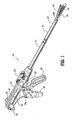
- FIG. 1 is a perspective view of a surgical stapling device in accordance with an embodiment of the present disclosure
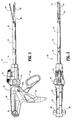
- FIG. 2 is a side elevation view of the surgical stapling device of FIG. 1 ;
- FIG, 3 is a top plan view of the surgical stapling device of FIGS. 1-2 ;
- FIG. 4 is a partial exploded view of the handle assembly for the surgical stapling device of FIGS. 1-3 ;
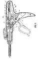
- FIG. 5 is a partial cross-sectional view of the surgical stapling device of FIGS. 1-4 ;
- FIG. 6 is a perspective view of the surgical stapling device of FIGS. 1-5 , showing the DLU separated from the device;
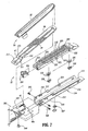
- FIG.7 is a partial, exploded perspective view of the DLU for the surgical stapling device of FIGS. 1-6 ;
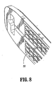
- FIG. 8 is a partial perspective view of the anvil member of the surgical stapling device of FIGS. 1-7 ;
- FIG. 9 is a partial, exploded perspective view of the DLU for the surgical stapling device of FIGS. 1-8 ;
- FIG. 10 is an exploded, perspective view of the tip assembly for the surgical stapling device of FIGS. 1-9 ;
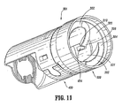
- FIG. 11 is a perspective view of the tip assembly for the surgical stapling device of FIGS. 1-10 ;
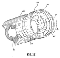
- FIG. 12 is a perspective view of the tip assembly for the surgical stapling device of FIGS. 1-11 ;
- FIG. 13 is a partial perspective view of the elongated body and tip assembly for the surgical stapling device of FIGS. 1-12 ;
- FIG. 14 is a partial, cross-sectional view of the tip assembly and DLU for the surgical stapling device of FIGS. 1-13 ;
- FIG. 15 is a partial, cross-sectional view of the tip assembly and DLU for the surgical stapling device of FIGS. 1-14 ;
- FIG. 16 is a partial, perspective view of the surgical stapling device of FIGS. 1-15 showing the elongated body;
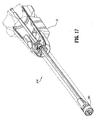
- FIG. 17 is a partial, perspective view, with parts removed, of the surgical stapling device of FIG. 16 , showing the elongated body;
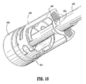
- FIG. 18 is a partial perspective view, with parts removed, of the surgical stapling device of FIGS. 1-17 , showing the tip assembly;
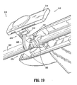
- FIG. 19 is a partial perspective view with parts removed of the surgical stapling device of FIGS. 1-18 , showing the locking structure;
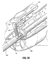
- FIG. 20 is a partial perspective view with parts removed of the surgical stapling device of FIGS. 1-19 , showing the locking structure;
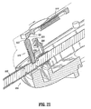
- FIG. 21 is a partial cross-sectional view with parts removed of the surgical stapling device of FIGS. 1-20 , showing the locking structure;
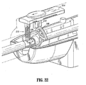
- FIG. 22 is a partial perspective view with parts removed of the surgical stapling device of FIGS. 1-21 , showing the locking structure;
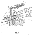
- FIG .23 is a partial cross-sectional view with parts removed of the surgical stapling device of FIGS. 1-22 , showing the locking structure.
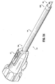
- FIG. 24 is a perspective view of a surgical stapling device, in accordance with another embodiment.
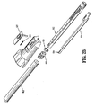
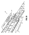
- FIG. 25 is an exploded, partial perspective view of the locking structure in accordance with the embodiment of FIG 24 ;
- FIG. 26 is a partial perspective view with parts removed of the locking structure in accordance with the embodiment of FIGS 24-25 ;
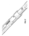
- FIG. 27 is another partial perspective view with parts removed of the locking structure in accordance with the embodiment of FIGS 24-26 ;
- FIG. 28 is a partial perspective view with parts removed of the locking structure in accordance with the embodiment of FIGS 24-27 .
- proximal will refer to the end of the stapling device which is closest to the operator, while the term “distal” will refer to the end of the device which is furthest from the operator.
- FIGS. 1-23 illustrate one preferred embodiment of the presently disclosed surgical stapling device shown generally as 10.
- surgical stapling device 10 includes a handle assembly 12 and an elongated body 14.
- the length of elongated body 14 may vary to suit a particular surgical procedure.
- the elongated body 14 defines a longitudinal axis for the device 10.
- a replaceable loading unit or DLU 16 is releasably secured to a distal end of elongated body 14.
- Loading unit 16 includes a proximal body portion 18, which forms an extension of elongated body 14, a distal tool assembly 20 including a cartridge assembly 22, and an anvil assembly 24.
- Tool assembly 20 is pivotably connected to body portion 18 about an axis substantially perpendicular to the longitudinal axis of elongated body 14.
- Cartridge assembly 22 houses a plurality of staples.
- Anvil assembly 24 is movable in relation to cartridge assembly 22 between an open position spaced from cartridge assembly 22 and an approximated or clamped position in juxtaposed alignment with cartridge assembly 24.
- the staples are housed in cartridge assembly 22 to apply rows of staples in body tissue.
- the rows of staples are linear rows of staples which may have a length measuring from about 30 mm to about 60 mm. Other staple configurations and lengths are envisioned.
- Handle assembly 12 includes a stationary handle member 26, a movable handle or trigger 28 and a barrel portion 30.
- a rotatable member 32 is preferably rotatably mounted to the forward end of barrel portion 30 and secured to elongated body 14 to facilitate rotation of elongated body 14 in relation to handle assembly 12.
- An articulation lever 122 is supported on a distal portion of barrel portion 30 and is operable, in a manner to be described hereafter, to effect articulation of tool assembly 20 with respect to body portion 18 of loading unit 16.
- a pair of return knobs 36 are movably supported along barrel portion 30.
- handle assembly 12 includes a housing 38, which is preferably formed from plastic molded housing half-sections 38a and 38b. Alternately, other materials may be used to form the housing including metals, e.g., stainless steel.
- Housing 38 forms stationary handle 26 and barrel portion 30 of handle assembly 12 (see FIG. 1 ).
- Movable handle 28 is rotatably supported between housing half-sections 38a and 38b about a cylindrical member 40 which is received within an opening 41 in movable handle 28.
- a biasing member 42 which is preferably a torsion spring, urges movable handle 28 away from stationary handle 26 to a non-compressed position.
- Movable handle 28 includes a pair of throughbores 46 dimensioned to receive a pivot member 47.
- a pawl 48 is rotatably supported on pivot member 47 and is biased by a spring 50 towards actuation shaft 52.
- Actuation shaft 52 is slidably supported between retracted and advanced positions within barrel portion 30 of housing 38 and includes a distal end defining a recess 54 configured to rotatably receive the proximal end 56 of firing rod 58.
- a spring biased retract arm 57 is rotatably mounted between housing half-sections 38a and 38b and includes an extension 57a. Extension 57a is positioned within a slot 59 ( FIG. 4 ) formed in actuation shaft 52 to urge actuation shaft 52 to a fully retracted position.
- Actuation shaft 52 includes a toothed rack 60.
- Pawl 48 has an engagement finger 62 which is biased by spring 50 towards toothed rack 60 of actuation shaft 52.
- movable handle 28 When movable handle 28 is actuated, i.e., is compressed towards stationary handle 26 against the bias of spring 42, engagement finger 62 of pawl 48 engages toothed rack 60 of actuation shaft 52 to advance actuation shaft 52 and firing rod 58 distally. Distal end of firing rod 58 engages proximal end of drive assembly 212 of the loading unit 16, when proximal end of loading unit 16 is engaged with elongated body 14 of surgical stapling device 10.
- the surgical stapling device includes a disposable loading unit or "DLU.”
- the loading units can include a tool assembly that can articulate with respect to the proximal body portion, or loading units that do not provide articulation.
- the loading units can include tool assemblies having linear rows of staples or other staple configurations. After firing staples from a loading unit, the loading unit can be removed from the device and a new loading unit may be assembled with the device.
- Loading unit 16 includes a tool assembly 20, a proximal body portion 18 and a mounting assembly 202 ( FIG. 9 ).
- Body portion 18 has a proximal end adapted to releasably engage the distal end of the elongated body 14 in the manner to be discussed in detail below.
- Mounting assembly 202 is pivotally secured to a distal end of body portion 18 and is fixedly secured to a proximal end of tool assembly 20. Pivotal movement of mounting assembly 202 pivots the tool assembly 20 so that a longitudinal axis of the tool assembly 20 is angled with respect to the longitudinal axis of the elongated body 14.
- Pivotal movement of mounting assembly 202 about an axis substantially perpendicular to the longitudinal axis of the elongated body 14 effects articulation of tool assembly 20 between a non-articulated position in which the longitudinal axis of tool assembly 20 is aligned with the longitudinal axis of elongated body 14 and an articulated position in which the longitudinal axis of tool assembly 20 is disposed at an angle to the longitudinal axis of elongated body 14.
- tool assembly 20 includes a cartridge assembly 22 and an anvil assembly 24.
- Anvil assembly 20 includes an anvil portion 28 having a plurality of staple deforming concavities 30 ( FIG. 8 ) and a cover plate 32 secured to a top surface of anvil portion 28. Cover plate 32 and anvil portion 28 define a cavity 34 therebetween. Cover plate 32 prevents pinching of tissue during actuation of loading unit 16 and advancement of the drive assembly 212 through the loading unit 16.
- a longitudinal slot 38 extends through anvil portion 28 to facilitate passage of a retention flange 40 of drive assembly 212.
- a camming surface 42 formed on anvil portion 28 is positioned to be engaged by a pair of cam members 40a supported on retention flange 40 of drive assembly 212 to effect approximation of the anvil and cartridge assemblies.
- a pair of pivot members 211 and a pair of stabilization members 215 are formed on the anvil portion 28.
- Cartridge assembly 22 includes carrier 216 which defines an elongated support channel 218 which is dimensioned and configured to receive staple cartridge 220.
- Carrier 216 has a pair of shoulders 217 and a pair of slots 213 defined in the carrier 216.
- the pair of slots 213 receives the pair of pivot members 211 to allow the anvil portion 28 to pivot with respect to the cartridge assembly 22.
- Each of the pair of stabilization members 215 engages a respective shoulder 217 to prevent the anvil portion 28 from sliding axially in relation to the staple cartridge 220 as the anvil portion 28 is pivoted about the pivot members 211.
- a pair of support struts 223 formed on staple cartridge 220 are positioned to rest on side walls of carrier 216 to further stabilize staple cartridge 220 within support channel 218.
- Staple cartridge 220 includes retention slots 225 ( FIG. 7 ) for receiving a plurality of staples or fasteners 226 and pushers 228.
- a plurality of laterally spaced apart longitudinal slots 230 extend through staple cartridge 220 to accommodate upstanding cam wedges 232 of an actuation sled 234 ( FIG. 7 ).
- a central longitudinal slot 282 extends along substantially the length of staple cartridge 220 to facilitate passage of the drive assembly 212 ( FIG. 9 ).
- drive assembly 212 is advanced by the firing rod 58.
- the drive assembly 212 abuts actuation sled 234 and pushes actuation sled 234 through longitudinal slots 230 of staple cartridge 220 to advance cam wedges 232 into sequential contact with pushers 228.
- Pushers 228 translate vertically along cam wedges 232 within fastener retention slots 225 and urge fasteners 226 from retention slots 225 into staple deforming cavities 30 ( FIG. 8 ) of anvil assembly 24.
- the drive assembly 212 includes a drive beam 266 with a working head 268.
- the distal end of working head 268 of drive beam 266 is defined by a vertical support strut 278 ( FIG.9 ) which supports a knife blade 280, and an abutment surface 283 which engages a portion of actuation sled 234 during a stapling procedure.
- Knife blade 280 is positioned to translate slightly behind the actuation sled 234 through a central longitudinal slot 282 in staple cartridge 220 to form an incision between rows of stapled body tissue.
- a retention flange 40 projects distally from vertical strut 278 and supports a cylindrical cam roller 40a at its distal end.
- Cam roller 40a is dimensioned and configured to engage cam surface 42 on anvil portion 28 to clamp anvil portion 28 against body tissue.
- movable handle 28 In use, the user manipulates handle assembly 12 to clamp tissue and fire staples. To approximate the cartridge and anvil assemblies 22 and 24 and clamp tissue, movable handle 28 is moved in the direction toward stationary handle member 26. Movable handle 28 is compressed towards stationary handle 26 against the bias of torsion spring 42 to engage actuation shaft 52. The engagement finger 62 of pawl 48 engages the toothed rack 60 of actuation shaft 52 to advance actuation shaft 52 and firing rod 58 distally.
- Firing rod 58 is connected at its distal end to axial drive assembly 212 including drive beam 266, such that advancement of firing rod 58 effects advancement of drive beam 266.
- drive beam 266 As drive beam 266 is advanced, cam roller 40a moves into engagement with cam surface 42 of anvil portion 28 to urge anvil portion 28 in the direction of the cartridge 220 to approximate cartridge and anvil assemblies 22 and 24 and clamp tissue therebetween.
- biasing member 42 After movable handle 28 is actuated to approximate cartridge and anvil assemblies 22 and 24, biasing member 42 returns handle to its non-compressed position spaced from stationary handle 26.
- the movable handle 28 is moved toward stationary handle member 26 through an actuation stroke during which, engagement finger 62 of pawl 48 engages toothed rack 60 of actuation shaft 52 to further advance actuation shaft 52 and firing rod 58 distally. More than one actuation stroke may be required to fire all the staples from the loading unit 16.
- drive beam 266 is advanced distally and engages actuation sled 234 through staple cartridge 22 to simultaneously sever tissue with knife 280 and drive pushers 228 to sequentially eject staples 226 from the cartridge.
- Loading units having staple lines of different lengths may be used and the number of actuating strokes will vary accordingly.
- the structure and operation of the tool assembly may be in accordance with certain embodiments disclosed in U.S. Patent No. 5,865,361 , the disclosure of which is hereby incorporated by reference herein.
- the elongated body 14 is mounted in a rotatable member 32 as shown in FIG. 5 and the rotatable member 32 is attached to the handle assembly 12 so as to allow the elongated body 14 and loading unit 16, including the tool assembly 20, to rotate around the longitudinal axis.
- the rotatable member 32 is formed from one or more tubular or conical members and houses an articulation actuation mechanism for articulating the tool assembly 20 with respect to the longitudinal axis of the device 10.
- the articulation actuation mechanism includes an articulation lever 122 ( FIG. 6 ).
- the articulation lever 122 is operably connected to an articulation arm extending through the elongated body 14.
- the articulation lever 122 may be connected to a mechanism for defining predetermined degrees of articulation of the tool assembly 20.
- the operation and structure of the articulation lever 122 may be as described in U.S. Published Patent Application No. 2004/0232201 , the disclosure of which is hereby incorporated by reference herein.
- the articulation lever 122 is mounted on the rotatable member 32 about a pivot pin and is attached to an articulation arm so that rotation of the lever 122 about the pivot pin effects longitudinal motion of the articulation arm.
- the articulation arm extends through the elongated body 14 and is attached to an articulation link 256 of the loading unit 16 ( FIG. 9 ) when the loading unit 16 is mounted on the elongated body 14.
- the articulation lever 122 can be rotated by the user of the surgical stapling device 10 to articulate the tool assembly 20. As the articulation lever 122 is rotated in a first direction, the articulation arm attached to the lever is advanced in the distal direction. The articulation arm advances the articulation link 256 of the loading unit 16 and pivots the mounting assembly 202 about pivot 244 to articulate the tool assembly 20 in the first direction. As the articulation lever 122 is rotated in a second direction, the articulation arm attached to the lever is retracted in the proximal direction. The articulation arm retracts the articulation link 256 of the loading unit 16 and pivots the mounting assembly 202 about pivot 244 to articulate the tool assembly 20 in the second direction.
- the loading unit 16 is removably mounted on the distal end of the elongated body 14.
- the body portion 18 of the loading unit 16 includes a first housing 250 and a second housing 252 that define a channel 253 for allowing the advancement of the axial drive assembly 212. ( FIG. 9 ).
- the housings 250 and 252 also define a slot for the articulation link 256.
- the housings 250 and 252 are received in an outer tube 251.
- the proximal ends of the housings 250 and 252 define an insertion tip 193 on which is formed a pair of lugs 254.
- the lugs 254 form a releasable connection with the elongated body 14 so that the loading unit 16 may be mounted on and removed from the elongated body 14.
- a pair of blowout plates 255 are positioned adjacent the distal end of the proximal body portion 18 and adjacent the mounting assembly 202. The blowout plates 255 support the drive assembly 212 during articulation and firing of the tool assembly 20. The structure and operation of the blowout plates 255 are described more fully in U.S. Published Patent Application Number 2004/0232201 , the disclosure of which is hereby incorporated by reference herein.
- the distal end of the elongated body 14 defines a tip assembly 301 for mounting the loading unit 16 thereon.
- FIGS. 10-15 and 18 show a tip assembly 301 according to the present disclosure.
- the tip assembly includes a ring 300 mounted to the distal end of the elongated body 14 so that it is rotationally fixed and a yoke 400 movably mounted to the ring 300. (See FIGS. 10 and 14 ).
- the ring 300 defines a passage 303 in which two helical guiding ramps 302 are formed. Each of the guiding ramps has a distal end 304 and a proximal end 306 and a ledge 310 adjacent the proximal end 306.
- a groove 312 is defined in the inner surface of the ring 300 for mounting the yoke 400 thereon. (See FIG. 10 ).
- the moveable yoke 400 has at least one protrusion for interacting with the lugs 254 on the loading unit 16. As shown in FIG. 11 , the protrusions include two tabs 402 and two stops 404 arranged in pairs so that each tab 402 and stop 404 define a receiving space 501.
- the distal end of the yoke 400 also has a ridge 406 which cooperates with the groove 312 of the ring 300 so that the yoke 400 is rotatable with respect to the ring 300 from a first, initial position to a second position. As the yoke 400 rotates, the positions of the tabs and stops with respect to the proximal ends 306 of the guiding ramps 302 change.
- a tab 402 and stop 404 pair are disposed adjacent one of the proximal ends 306 of one of the guiding ramps 302, so that receiving space 501 is positioned for receiving one of the lugs 254 of the loading unit 16.
- the tab 402 and stop 404 pair are positioned so that the receiving space 501, and the lug 254 disposed therein, is disposed beneath the ledge 310.
- the loading unit 16 is inserted into the tip assembly 301 so that the insertion tip 193 is inserted into passage 303.
- the lugs 254 are advanced into the passage 303 of the ring 300 and contact the distal ends 304 of the guiding ramps 302. (See FIG. 11 ).
- the loading unit 16 is rotated in Direction A (see FIG 12 )
- the lugs 254 are guided on the guiding ramps 302 towards the proximal ends 306 of the guiding ramps 302 and drop into the receiving spaces 501 of the yoke 400.
- FIG. 14 shows the lugs 254 in the receiving spaces 501.
- the tip assembly 301 is still in the first position and a stop 404 and tab 408 are disposed on either side of a lug 254, and adjacent a proximal end 306 of one of the guiding ramps 302.
- the loading unit 16 may be moved distally and removed from the elongated body 14.
- the user continues to rotate the loading unit 16 in Direction A, so that lugs 254 push against the tabs 402, thereby rotating moveable yoke 400 into the second position, as shown in FIG. 12 .
- the lugs 254 are situated beneath ledges 310.
- FIG. 15 shows the lugs 254 positioned beneath ledges 310.
- the stops 404 prevent the loading unit 16 from rotating with respect to the yoke 400.
- the loading unit 16 is captured in the tip assembly 301 and cannot be moved without rotating the yoke 400.
- a distal end of the firing rod 58 is connected to the proximal end of the drive assembly 212.
- the proximal end of the drive assembly 212 includes a drive member 272 with a porthole for receiving the distal end of the firing rod 58.
- the loading unit 16 is rotated in the direction opposite to Direction A, rotating the yoke 400 with it.
- the lugs 254 are thereby moved away from the ledges 310.
- the articulation link 256 and the articulation arm are moved away from engagement with one another as the loading unit is rotated.
- the loading unit 16 can be removed from the device by continuing to rotate the loading unit 16 so that the lugs 254 follow the guiding ramps 302 toward the distal ends 304 and moving the DLU distally.
- the firing rod 58 is disengaged from the drive assembly 212.
- the surgical stapling device 10 includes a sensor mechanism 510 and a locking structure 513, as shown in FIGS 16-23 .
- the sensor mechanism 510 and the locking structure 513 interact with the tip assembly 301 ( FIG. 17 ) to secure the loading unit 16 onto the elongated body 14.
- the sensor mechanism 510 and locking structure 513 release the loading unit 16 from the elongated body 14.
- the locking structure 513 locks the firing rod 58 in position until the loading unit 16 is loaded onto the elongated body 14.
- the sensor mechanism 510 includes a sensor tube 502 having a distal end with a groove 504, as shown in FIG. 18 .
- the yoke 400 of the tip assembly 301 has a protrusion 407 that engages the groove 504 and keys movement of the yoke 400 to the sensor tube 502.
- the proximal end of the sensor tube 502 is connected to the locking structure 513.
- the locking structure 513 includes a button 514 or other manipulatable actuator at the proximal end of the elongated body 14, or on the handle assembly 12, so that it is accessible to the user of the device 10.
- the button 514 is shown in FIG.
- the button 514 has a button tang 512 that extends toward the sensor tube 502.
- a release flange 508 is attached to the sensor tube 502 and rotates with the sensor tube 502 from a first position away from button tang 512 ( FIG. 20 ) to a second position in which movement of the release flange 508 is blocked by button tang 512 of locking structure 513 ( FIG. 19 ).
- the button 514 is biased in the distal direction by a spring.
- a plunger 516 interacts with the firing rod 58.
- the firing rod 58 proximal end 524 has a notch 526 defined therein, as best seen in FIGS. 20-23 .
- the plunger 516 has a first end for engaging the firing rod 58 at the notch 526 and a second end with a beveled surface 522 that is positioned so as to communicate with the button 514 ( FIGS. 21 and 23 ).
- the plunger 516 is biased in a direction away from the firing rod 58.
- the locking structure 510 engages the firing rod 58 in the notch 526, preventing the advancement of the firing rod 58.
- the release flange 508 prevents the button 514 from moving distally so that the button 514 maintains the plunger 516 in engagement with the notch 526.
- the yoke 400 is turned, thereby turning the sensor tube 502.
- the release flange 508 moves away from button tang 512, allowing the button 514 to move distally.
- the button 514 allows the plunger 516 to move away from notch 526, as shown in FIG. 23 .
- the locking structure 510 has been disengaged from firing rod 58, allowing the firing rod 58 to move when the moveable handle 28 is manipulated and the device 10 is actuated to clamp tissue and fire staples.
- the loading unit 16 is also locked onto the device 10, as the release lever 508 is blocked by the button tang 512, preventing rotation of the sensor tube 502. With the sensor tube 502 prevented from rotation, the yoke 400, which holds the loading unit 16 onto the device 10, is prevented from rotation.
- button 514 of locking structure 510 is moved against the bias of the button spring, as shown in FIG. 21 , moving button tang 512 away from release flange 508, as shown in FIG. 20 .
- the loading unit 16 can then be rotated and removed from the tip assembly 301 on the elongated body 14.
- the locking structure 510 engages the firing rod 58, as the button 514 cams the plunger 516 downwardly into the notch 526, as shown in FIG. 21 .
- a locking structure and/ or sensor mechanism in accordance with the present disclosure may be used to secure any surgical loading unit, such as a staple cartridge, replaceable tool assembly, or other end effector, while providing for the release of the same from a surgical instrument.
- the manipulatable actuator for releasing and/or locking the surgical loading unit is disposed adjacent the handle assembly.
- the manipulatable actuator is disposed at or adjacent to the proximal end of the endoscopic shaft or elongated body.
- the retraction mechanism includes return knobs 36 ( FIG. 1 ) which are connected to the proximal end of actuation shaft 52 by a coupling rod 82 ( FIG. 4 ).
- Coupling rod 82 has right and left engagement portions 82a and 82b which extend through elongated slots 83 ( FIG. 1 ) formed in housing half-sections 38a and 38b and are configured to receive return knobs 36.
- a central portion 82c of coupling rod 82 is dimensioned to be slidably received within slots 84 formed in the proximal end of actuation shaft 52.
- a release plate 86 is supported on one side of actuation shaft 52 by a pair of pins 88 ( FIG. 4 ). Pins 88 are positioned within angled cam slots 90 formed through release plate 86. Coupling rod 82 extends through an opening 92 formed in the proximal end of release plate 86.
- coupling rod 82 In use, when knobs 36 are pulled rearwardly by a surgeon, coupling rod 82 initially moves release plate 86 rearwardly in relation to actuation shaft 52 as rod 82 slides in slots 84 of actuation shaft 52. As this occurs, pins 88 cam release plate 86 downwardly to a position covering toothed rack 60 of actuation shaft 52 to disengage finger 62 of pawl 48 from toothed rack 60. When coupling rod 82 is pulled rearwardly to a position at which it engages the back end 84a of slots 84, additional rearward movement of knobs 36 effect proximal movement of actuation shaft 52 and firing rod 58.
- a hook 96 is supported in a slot 98 formed in a top surface of actuation shaft 52.
- Hook 96 includes a throughbore 96a dimensioned to receive coupling rod 82.
- a forward end of hook 96 includes an upturned portion 98 configured to receive one looped end 100a of spring 100.
- the opposite end of spring 100 includes a loop 100b dimensioned to receive a post 102 formed on actuation shaft 52.
- Spring 100 is maintained in tension to urge coupling rod 82 towards the forward end of slots 84 in actuation shaft 52.
- a locking structure 600 in another embodiment shown in FIGS. 24-28 , includes a button assembly 602 and an elongated housing 604.
- the locking structure 600 has a first position ( FIG 27 ) for locking loading unit 620 and a second position ( FIG 26 ) for unlocking and disengaging loading unit 620.
- the elongated housing 604 includes an outer tube 622, tube housing 612, and loading portion 606 at the distal end 604b thereof.
- the locking shaft 614 extends through elongated housing 604 and is shaped to be received by a recess in the tube housing 612 so that the locking shaft 614 is slideable with respect to the tube housing 612 and rotationally fixed with respect to the tube housing 612.
- the tube housing 612 and locking shaft 614 also define a notch 613 for receiving spring 618 therebetween.
- the loading portion 606 is configured to receive one or more lugs 610 on the loading unit 620 and guides movement of the loading unit 620 onto device 10.
- the tube housing 612 and locking shaft 614 define a space 611 for receiving and locking a lug 610a of the loading unit 620.
- the tube housing 612 has a shelf 616 on a proximal side of the space 611, an edge 612a on a distal side of the space 611, and edges 612b and 612c on lateral sides of the space 611.
- the locking shaft 614 has a distally-facing surface 614a, another distally-facing surface 614c, and a longitudinal surface 614b extending therebetween. As best seen in FIG. 26 , the distal end of the locking shaft 614 which is defined by the surfaces 614a, 614b, and 614c, has a stepped shape.
- a seal 624 and end cap 626 is disposed at the proximal end 604a of the elongated housing 604.
- the seal 624 is circular in shape and includes 2 walls, which define separate chambers. In a preferred embodiment, the seal 624 and end cap 626 slide over the tube housing 612, as best seen in FIG. 25 .
- the seal 624 has three chambers. The three chambers receive the locking shaft 614, tube housing 612 and an articulation rod (not shown). End cap 626 is in communication with the seal 624, and, upon assembly, the seal 624 presses against the outer tube 622.
- the locking structure 600 includes a button assembly 602, located at the proximal end of the elongated housing 604, which is moveable between a first locked position and a second unlocked position.
- Button assembly 602 includes a return spring 633 ( FIG 25 ) which biases the button 631 distally.
- the button 631 defines a protrusion 632 which engages a slot 634 on the locking shaft 614. Through the interaction of the slot 634 and protrusion 632 the button 631 and locking shaft 614 are moveable between a first and second position as the button 631 is moved by user.
- the elongated housing 604 defines a loading portion 606 dimensioned to receive the lugs 610.
- the tube housing 612 has a groove forming a guiding channel 608 which guides movement of the loading unit 620.
- lug 610a abuts the surface 614a of the locking shaft 614, moving the locking shaft 614 proximally.
- a shelf 616, located on tube housing 612, abuts the lug 610a, thus preventing further movement proximally.
- the loading unit 620 is rotated in Direction A shown in FIG. 26 , toward edge 612c.
- the locking shaft 614 When the lug 610a is aligned with surface 614c, the locking shaft 614 will move distally under the influence of spring 618. The lug 610a is captured between edges 614b, 614c and surfaces 612a, 612c, as shown in FIG. 26 , preventing rotational and longitudinal movement.
- locking shaft 614 When the user moves the button assembly 630 proximally, against the bias of the spring 618, locking shaft 614 is moved rearwardly, the locking structure 600 disengages loading unit 620 ( FIG. 26 ) and loading unit 620 can be removed.
- the button assembly 630 To remove the loading unit 620, the button assembly 630 is moved rearwardly, sliding locking shaft 614 proximally across tube housing 612. The loading unit 620 is removed from the loading portion 606 by rotating the loading portion 606 in the direction opposite to Direction A.
- the above described lock assembly may be incorporated into a variety of surgical instruments which include loading units and is not limited to use on endoscopic staplers.
- the loading unit may be configured to receive an insertion tip of a surgical instrument in contrast to that disclosed. Therefore, the above description should not be construed as limiting, but merely as exemplifications of various embodiments. Those skilled in the art will envision other modifications within the scope and spirit of the claims appended hereto. The invention will now be described in further detail in the following numbered paragraphs:
Abstract
Description
- This application is a continuation in part of
U.S. Patent application Serial Number 11/701,116, filed January 31, 2007 - This application relates to a surgical stapling device for applying staples to tissue having a locking mechanism for securing a loading unit onto the surgical stapling device.
- Surgical devices for applying surgical fasteners to tissue are well known. Endoscopic surgical devices for applying staples, clips or other fasteners include a handle assembly for actuating the device, an endoscopic shaft and a tool assembly at the distal end of the endoscopic shaft. Certain of these devices are designed for use with replaceable loading units housing the staples or fasteners. For example, in using an endoscopic linear stapler, the user may select a loading unit with staples of a selected size and arranged in one or more lines of staples having a selected staple line length. After firing, the user may remove the loading unit, select another loading unit of the same or different size, and fire staples from the instrument again. Endoscopic surgical staplers having four lines of staples, arranged in pairs on either side of a cut line, are known.
- Loading units in the form of replaceable cartridges are known. In addition, loading units having a tool assembly, including a cartridge, anvil, drive assembly and knife are known. Such loading units have the benefit of providing a new knife with each loading of the loading unit.
- Although interfaces between the surgical stapling device endoscopic shaft and the loading unit are known, improvements in the ease of loading and unloading of the loading unit are desired.
- In a first aspect of the present invention, a surgical instrument comprises an elongated housing having a proximal end and a distal end. A loading unit is removably mountable with the distal end of the elongated housing and has a tool assembly. The loading unit has at least one lug thereon. A handle assembly is at the proximal end of the elongated housing. A locking structure has a first position for locking movement of the loading unit and a second position for allowing movement of the loading unit. The locking structure includes a locking shaft that extends through the elongated housing to the handle assembly. The locking shaft has a surface engaging the at least one lug in the first position of the locking structure and disengaging the at least one lug in the second position of the locking structure. The elongated housing desirably defines at least one guiding channel for engagement with the at least one lug.
- The surgical instrument further includes a rod extending through the elongated housing, and a drive assembly. The drive assembly is connected to the rod when the loading unit is mounted on the elongated housing. The locking structure may engage the rod when the locking structure is in the second position.
- The locking structure preferably includes a button assembly including a button and the button is preferably adjacent the proximal end of the elongated housing. The button may be distally biased and moveable between a first position and a second position.
- The locking shaft may define a slot for engaging a protrusion on the button. The locking shaft may have a first distally-facing surface, a second distally-facing surface and a longitudinal surface extending therebetween. The at least one lug is desirably captured between the first distally-facing surface, second distally-facing surface, a longitudinal surface of the locking shaft, and the elongated housing when the locking structure is in the first position. The locking shaft and the elongated housing desirably define a space for capturing the at least one lug therebetween.
- In a further aspect of the present invention, a surgical instrument comprises an elongated housing having a proximal end and a distal end, a loading unit removably mountable with the distal end of the elongated housing and having a tool assembly, and a handle assembly at the proximal end of the elongated housing. A rotation member is at the proximal end of the elongated housing and the surgical instrument has a locking structure for securing the loading unit on the elongated housing, the locking structure including a button accessible at the rotation member.
- The locking structure has a first position for locking movement of the loading unit and a second position for allowing movement of the loading unit. The locking structure includes a locking shaft that extends through the elongated housing to the proximal end of the elongated housing.
- Various preferred embodiments of the presently disclosed surgical stapling device are described herein with reference to the drawings, in which:
-
FIG. 1 is a perspective view of a surgical stapling device in accordance with an embodiment of the present disclosure; -
FIG. 2 is a side elevation view of the surgical stapling device ofFIG. 1 ; -
FIG, 3 is a top plan view of the surgical stapling device ofFIGS. 1-2 ; -
FIG. 4 is a partial exploded view of the handle assembly for the surgical stapling device ofFIGS. 1-3 ; -
FIG. 5 is a partial cross-sectional view of the surgical stapling device ofFIGS. 1-4 ; -
FIG. 6 is a perspective view of the surgical stapling device ofFIGS. 1-5 , showing the DLU separated from the device; -
FIG.7 is a partial, exploded perspective view of the DLU for the surgical stapling device ofFIGS. 1-6 ; -
FIG. 8 is a partial perspective view of the anvil member of the surgical stapling device ofFIGS. 1-7 ; -
FIG. 9 is a partial, exploded perspective view of the DLU for the surgical stapling device ofFIGS. 1-8 ; -
FIG. 10 is an exploded, perspective view of the tip assembly for the surgical stapling device ofFIGS. 1-9 ; -
FIG. 11 is a perspective view of the tip assembly for the surgical stapling device ofFIGS. 1-10 ; -
FIG. 12 is a perspective view of the tip assembly for the surgical stapling device ofFIGS. 1-11 ; -
FIG. 13 is a partial perspective view of the elongated body and tip assembly for the surgical stapling device ofFIGS. 1-12 ; -
FIG. 14 is a partial, cross-sectional view of the tip assembly and DLU for the surgical stapling device ofFIGS. 1-13 ; -
FIG. 15 is a partial, cross-sectional view of the tip assembly and DLU for the surgical stapling device ofFIGS. 1-14 ; -
FIG. 16 is a partial, perspective view of the surgical stapling device ofFIGS. 1-15 showing the elongated body; -
FIG. 17 is a partial, perspective view, with parts removed, of the surgical stapling device ofFIG. 16 , showing the elongated body; -
FIG. 18 is a partial perspective view, with parts removed, of the surgical stapling device ofFIGS. 1-17 , showing the tip assembly; -
FIG. 19 is a partial perspective view with parts removed of the surgical stapling device ofFIGS. 1-18 , showing the locking structure; -
FIG. 20 is a partial perspective view with parts removed of the surgical stapling device ofFIGS. 1-19 , showing the locking structure; -
FIG. 21 is a partial cross-sectional view with parts removed of the surgical stapling device ofFIGS. 1-20 , showing the locking structure; -
FIG. 22 is a partial perspective view with parts removed of the surgical stapling device ofFIGS. 1-21 , showing the locking structure; and -
FIG .23 is a partial cross-sectional view with parts removed of the surgical stapling device ofFIGS. 1-22 , showing the locking structure. -
FIG. 24 is a perspective view of a surgical stapling device, in accordance with another embodiment; -
FIG. 25 is an exploded, partial perspective view of the locking structure in accordance with the embodiment ofFIG 24 ; -
FIG. 26 is a partial perspective view with parts removed of the locking structure in accordance with the embodiment ofFIGS 24-25 ; -
FIG. 27 is another partial perspective view with parts removed of the locking structure in accordance with the embodiment ofFIGS 24-26 ; and -
FIG. 28 is a partial perspective view with parts removed of the locking structure in accordance with the embodiment ofFIGS 24-27 . - Preferred embodiments of the presently disclosed surgical stapling device will now be described in detail with reference to the drawings in which like reference numerals designate identical or corresponding elements in each of the several views.
- In the description that follows, the term "proximal" will refer to the end of the stapling device which is closest to the operator, while the term "distal" will refer to the end of the device which is furthest from the operator.
-
FIGS. 1-23 illustrate one preferred embodiment of the presently disclosed surgical stapling device shown generally as 10. Briefly,surgical stapling device 10 includes ahandle assembly 12 and anelongated body 14. The length ofelongated body 14 may vary to suit a particular surgical procedure. Theelongated body 14 defines a longitudinal axis for thedevice 10. A replaceable loading unit orDLU 16 is releasably secured to a distal end ofelongated body 14.Loading unit 16 includes aproximal body portion 18, which forms an extension ofelongated body 14, adistal tool assembly 20 including acartridge assembly 22, and ananvil assembly 24.Tool assembly 20 is pivotably connected tobody portion 18 about an axis substantially perpendicular to the longitudinal axis ofelongated body 14.Cartridge assembly 22 houses a plurality of staples.Anvil assembly 24 is movable in relation tocartridge assembly 22 between an open position spaced fromcartridge assembly 22 and an approximated or clamped position in juxtaposed alignment withcartridge assembly 24. The staples are housed incartridge assembly 22 to apply rows of staples in body tissue. For example, in the embodiment shown, the rows of staples are linear rows of staples which may have a length measuring from about 30 mm to about 60 mm. Other staple configurations and lengths are envisioned. - Handle
assembly 12 includes astationary handle member 26, a movable handle or trigger 28 and abarrel portion 30. Arotatable member 32 is preferably rotatably mounted to the forward end ofbarrel portion 30 and secured toelongated body 14 to facilitate rotation ofelongated body 14 in relation to handleassembly 12. Anarticulation lever 122 is supported on a distal portion ofbarrel portion 30 and is operable, in a manner to be described hereafter, to effect articulation oftool assembly 20 with respect tobody portion 18 ofloading unit 16. A pair ofreturn knobs 36 are movably supported alongbarrel portion 30. - Referring to
FIGS.4-7 , handleassembly 12 includes ahousing 38, which is preferably formed from plastic molded housing half-sections 38a and 38b. Alternately, other materials may be used to form the housing including metals, e.g., stainless steel.Housing 38 formsstationary handle 26 andbarrel portion 30 of handle assembly 12 (seeFIG. 1 ).Movable handle 28 is rotatably supported between housing half-sections 38a and 38b about acylindrical member 40 which is received within anopening 41 inmovable handle 28. A biasingmember 42, which is preferably a torsion spring, urgesmovable handle 28 away fromstationary handle 26 to a non-compressed position.Movable handle 28 includes a pair ofthroughbores 46 dimensioned to receive apivot member 47. Apawl 48 is rotatably supported onpivot member 47 and is biased by aspring 50 towardsactuation shaft 52. -
Actuation shaft 52 is slidably supported between retracted and advanced positions withinbarrel portion 30 ofhousing 38 and includes a distal end defining arecess 54 configured to rotatably receive theproximal end 56 of firingrod 58. A spring biased retractarm 57 is rotatably mounted between housing half-sections 38a and 38b and includes an extension 57a. Extension 57a is positioned within a slot 59 (FIG. 4 ) formed inactuation shaft 52 to urgeactuation shaft 52 to a fully retracted position.Actuation shaft 52 includes atoothed rack 60.Pawl 48 has an engagement finger 62 which is biased byspring 50 towardstoothed rack 60 ofactuation shaft 52. Whenmovable handle 28 is actuated, i.e., is compressed towardsstationary handle 26 against the bias ofspring 42, engagement finger 62 ofpawl 48 engagestoothed rack 60 ofactuation shaft 52 to advanceactuation shaft 52 and firingrod 58 distally. Distal end of firingrod 58 engages proximal end ofdrive assembly 212 of theloading unit 16, when proximal end ofloading unit 16 is engaged withelongated body 14 ofsurgical stapling device 10. - The surgical stapling device includes a disposable loading unit or "DLU." A loading unit having the desired staple size or sizes, and the desired staple line length, is assembled with the device. The loading units can include a tool assembly that can articulate with respect to the proximal body portion, or loading units that do not provide articulation. The loading units can include tool assemblies having linear rows of staples or other staple configurations. After firing staples from a loading unit, the loading unit can be removed from the device and a new loading unit may be assembled with the device.
- Referring to
FIGS. 1 and7-9 , a loading unit with an articulating tool assembly is shown.Loading unit 16 includes atool assembly 20, aproximal body portion 18 and a mounting assembly 202 (FIG. 9 ).Body portion 18 has a proximal end adapted to releasably engage the distal end of theelongated body 14 in the manner to be discussed in detail below. Mountingassembly 202 is pivotally secured to a distal end ofbody portion 18 and is fixedly secured to a proximal end oftool assembly 20. Pivotal movement of mountingassembly 202 pivots thetool assembly 20 so that a longitudinal axis of thetool assembly 20 is angled with respect to the longitudinal axis of theelongated body 14. Pivotal movement of mountingassembly 202 about an axis substantially perpendicular to the longitudinal axis of theelongated body 14 effects articulation oftool assembly 20 between a non-articulated position in which the longitudinal axis oftool assembly 20 is aligned with the longitudinal axis ofelongated body 14 and an articulated position in which the longitudinal axis oftool assembly 20 is disposed at an angle to the longitudinal axis ofelongated body 14. - Referring to
FIGS. 7-9 ,tool assembly 20 includes acartridge assembly 22 and ananvil assembly 24.Anvil assembly 20 includes ananvil portion 28 having a plurality of staple deforming concavities 30 (FIG. 8 ) and acover plate 32 secured to a top surface ofanvil portion 28.Cover plate 32 andanvil portion 28 define acavity 34 therebetween.Cover plate 32 prevents pinching of tissue during actuation ofloading unit 16 and advancement of thedrive assembly 212 through theloading unit 16. Alongitudinal slot 38 extends throughanvil portion 28 to facilitate passage of aretention flange 40 ofdrive assembly 212. Acamming surface 42 formed onanvil portion 28 is positioned to be engaged by a pair ofcam members 40a supported onretention flange 40 ofdrive assembly 212 to effect approximation of the anvil and cartridge assemblies. A pair ofpivot members 211 and a pair ofstabilization members 215 are formed on theanvil portion 28. -
Cartridge assembly 22 includescarrier 216 which defines anelongated support channel 218 which is dimensioned and configured to receivestaple cartridge 220.Carrier 216 has a pair ofshoulders 217 and a pair ofslots 213 defined in thecarrier 216. The pair ofslots 213 receives the pair ofpivot members 211 to allow theanvil portion 28 to pivot with respect to thecartridge assembly 22. Each of the pair ofstabilization members 215 engages arespective shoulder 217 to prevent theanvil portion 28 from sliding axially in relation to thestaple cartridge 220 as theanvil portion 28 is pivoted about thepivot members 211. Correspondingtabs 222 andslots 224 formed alongstaple cartridge 220 andelongated support channel 218, respectively, function to retainstaple cartridge 220 at a fixed location withinsupport channel 218. A pair of support struts 223 formed onstaple cartridge 220 are positioned to rest on side walls ofcarrier 216 to further stabilizestaple cartridge 220 withinsupport channel 218. -
Staple cartridge 220 includes retention slots 225 (FIG. 7 ) for receiving a plurality of staples orfasteners 226 andpushers 228. A plurality of laterally spaced apartlongitudinal slots 230 extend throughstaple cartridge 220 to accommodateupstanding cam wedges 232 of an actuation sled 234 (FIG. 7 ). A centrallongitudinal slot 282 extends along substantially the length ofstaple cartridge 220 to facilitate passage of the drive assembly 212 (FIG. 9 ). During operation ofsurgical stapling device 10,drive assembly 212 is advanced by the firingrod 58. Thedrive assembly 212 abutsactuation sled 234 and pushesactuation sled 234 throughlongitudinal slots 230 ofstaple cartridge 220 to advancecam wedges 232 into sequential contact withpushers 228.Pushers 228 translate vertically alongcam wedges 232 withinfastener retention slots 225 andurge fasteners 226 fromretention slots 225 into staple deforming cavities 30 (FIG. 8 ) ofanvil assembly 24. - The
drive assembly 212 includes adrive beam 266 with a working head 268. The distal end of working head 268 ofdrive beam 266 is defined by a vertical support strut 278 (FIG.9 ) which supports aknife blade 280, and anabutment surface 283 which engages a portion ofactuation sled 234 during a stapling procedure.Knife blade 280 is positioned to translate slightly behind theactuation sled 234 through a centrallongitudinal slot 282 instaple cartridge 220 to form an incision between rows of stapled body tissue. Aretention flange 40 projects distally fromvertical strut 278 and supports acylindrical cam roller 40a at its distal end.Cam roller 40a is dimensioned and configured to engagecam surface 42 onanvil portion 28 to clampanvil portion 28 against body tissue. - In use, the user manipulates
handle assembly 12 to clamp tissue and fire staples. To approximate the cartridge andanvil assemblies movable handle 28 is moved in the direction towardstationary handle member 26.Movable handle 28 is compressed towardsstationary handle 26 against the bias oftorsion spring 42 to engageactuation shaft 52. The engagement finger 62 ofpawl 48 engages thetoothed rack 60 ofactuation shaft 52 to advanceactuation shaft 52 and firingrod 58 distally. - Firing
rod 58 is connected at its distal end toaxial drive assembly 212 includingdrive beam 266, such that advancement of firingrod 58 effects advancement ofdrive beam 266. Asdrive beam 266 is advanced,cam roller 40a moves into engagement withcam surface 42 ofanvil portion 28 to urgeanvil portion 28 in the direction of thecartridge 220 to approximate cartridge andanvil assemblies - After
movable handle 28 is actuated to approximate cartridge andanvil assemblies member 42 returns handle to its non-compressed position spaced fromstationary handle 26. - To fire stapling
device 10 once tissue is clamped, themovable handle 28 is moved towardstationary handle member 26 through an actuation stroke during which, engagement finger 62 ofpawl 48 engagestoothed rack 60 ofactuation shaft 52 to further advanceactuation shaft 52 and firingrod 58 distally. More than one actuation stroke may be required to fire all the staples from theloading unit 16. As firingrod 58 is advanced in the manner discussed above,drive beam 266 is advanced distally and engagesactuation sled 234 throughstaple cartridge 22 to simultaneously sever tissue withknife 280 and drivepushers 228 to sequentiallyeject staples 226 from the cartridge. Loading units having staple lines of different lengths may be used and the number of actuating strokes will vary accordingly. The structure and operation of the tool assembly may be in accordance with certain embodiments disclosed inU.S. Patent No. 5,865,361 , the disclosure of which is hereby incorporated by reference herein. - The
elongated body 14 is mounted in arotatable member 32 as shown inFIG. 5 and therotatable member 32 is attached to thehandle assembly 12 so as to allow theelongated body 14 andloading unit 16, including thetool assembly 20, to rotate around the longitudinal axis. Therotatable member 32 is formed from one or more tubular or conical members and houses an articulation actuation mechanism for articulating thetool assembly 20 with respect to the longitudinal axis of thedevice 10. The articulation actuation mechanism includes an articulation lever 122 (FIG. 6 ). Thearticulation lever 122 is operably connected to an articulation arm extending through theelongated body 14. Thearticulation lever 122 may be connected to a mechanism for defining predetermined degrees of articulation of thetool assembly 20. The operation and structure of thearticulation lever 122 may be as described inU.S. Published Patent Application No. 2004/0232201 , the disclosure of which is hereby incorporated by reference herein. Thearticulation lever 122 is mounted on therotatable member 32 about a pivot pin and is attached to an articulation arm so that rotation of thelever 122 about the pivot pin effects longitudinal motion of the articulation arm. The articulation arm extends through theelongated body 14 and is attached to anarticulation link 256 of the loading unit 16 (FIG. 9 ) when theloading unit 16 is mounted on theelongated body 14. Thearticulation lever 122 can be rotated by the user of thesurgical stapling device 10 to articulate thetool assembly 20. As thearticulation lever 122 is rotated in a first direction, the articulation arm attached to the lever is advanced in the distal direction. The articulation arm advances thearticulation link 256 of theloading unit 16 and pivots the mountingassembly 202 aboutpivot 244 to articulate thetool assembly 20 in the first direction. As thearticulation lever 122 is rotated in a second direction, the articulation arm attached to the lever is retracted in the proximal direction. The articulation arm retracts thearticulation link 256 of theloading unit 16 and pivots the mountingassembly 202 aboutpivot 244 to articulate thetool assembly 20 in the second direction. - As depicted in
FIG. 6 , theloading unit 16 is removably mounted on the distal end of theelongated body 14. Thebody portion 18 of theloading unit 16 includes afirst housing 250 and asecond housing 252 that define achannel 253 for allowing the advancement of theaxial drive assembly 212. (FIG. 9 ). Thehousings articulation link 256. Thehousings outer tube 251. The proximal ends of thehousings insertion tip 193 on which is formed a pair oflugs 254. Thelugs 254 form a releasable connection with theelongated body 14 so that theloading unit 16 may be mounted on and removed from theelongated body 14. A pair ofblowout plates 255 are positioned adjacent the distal end of theproximal body portion 18 and adjacent the mountingassembly 202. Theblowout plates 255 support thedrive assembly 212 during articulation and firing of thetool assembly 20. The structure and operation of theblowout plates 255 are described more fully inU.S. Published Patent Application Number 2004/0232201 , the disclosure of which is hereby incorporated by reference herein. - The distal end of the
elongated body 14 defines atip assembly 301 for mounting theloading unit 16 thereon.FIGS. 10-15 and18 show atip assembly 301 according to the present disclosure. The tip assembly includes aring 300 mounted to the distal end of theelongated body 14 so that it is rotationally fixed and ayoke 400 movably mounted to thering 300. (SeeFIGS. 10 and14 ). Thering 300 defines apassage 303 in which two helical guiding ramps 302 are formed. Each of the guiding ramps has adistal end 304 and aproximal end 306 and aledge 310 adjacent theproximal end 306. Agroove 312 is defined in the inner surface of thering 300 for mounting theyoke 400 thereon. (SeeFIG. 10 ). - The
moveable yoke 400 has at least one protrusion for interacting with thelugs 254 on theloading unit 16. As shown inFIG. 11 , the protrusions include twotabs 402 and twostops 404 arranged in pairs so that eachtab 402 and stop 404 define a receivingspace 501. The distal end of theyoke 400 also has aridge 406 which cooperates with thegroove 312 of thering 300 so that theyoke 400 is rotatable with respect to thering 300 from a first, initial position to a second position. As theyoke 400 rotates, the positions of the tabs and stops with respect to the proximal ends 306 of the guidingramps 302 change. In the first position of theyoke 400 as shown inFIG. 11 , atab 402 and stop 404 pair are disposed adjacent one of the proximal ends 306 of one of the guidingramps 302, so that receivingspace 501 is positioned for receiving one of thelugs 254 of theloading unit 16. In the second position of theyoke 400 as shown inFIG. 12 , thetab 402 and stop 404 pair are positioned so that the receivingspace 501, and thelug 254 disposed therein, is disposed beneath theledge 310. - The
loading unit 16 is inserted into thetip assembly 301 so that theinsertion tip 193 is inserted intopassage 303. Thelugs 254 are advanced into thepassage 303 of thering 300 and contact the distal ends 304 of the guiding ramps 302. (SeeFIG. 11 ). When theloading unit 16 is rotated in Direction A (seeFIG 12 ), thelugs 254 are guided on the guidingramps 302 towards the proximal ends 306 of the guidingramps 302 and drop into the receivingspaces 501 of theyoke 400.FIG. 14 shows thelugs 254 in the receivingspaces 501. Thetip assembly 301 is still in the first position and astop 404 and tab 408 are disposed on either side of alug 254, and adjacent aproximal end 306 of one of the guiding ramps 302. In this position, theloading unit 16 may be moved distally and removed from theelongated body 14. The user continues to rotate theloading unit 16 in Direction A, so that lugs 254 push against thetabs 402, thereby rotatingmoveable yoke 400 into the second position, as shown inFIG. 12 . Thelugs 254 are situated beneathledges 310.FIG. 15 shows thelugs 254 positioned beneathledges 310. Thestops 404 prevent theloading unit 16 from rotating with respect to theyoke 400. Thus, theloading unit 16 is captured in thetip assembly 301 and cannot be moved without rotating theyoke 400. - As the
loading unit 16 is mounted on to the distal end of theelongated body 14, a distal end of the firingrod 58 is connected to the proximal end of thedrive assembly 212. The proximal end of thedrive assembly 212 includes adrive member 272 with a porthole for receiving the distal end of the firingrod 58. When theloading unit 16 is rotated during mounting of the loading unit, thearticulation link 256 moves into engagement with engagement structure on the distal end of the articulation arm. - To remove the
loading unit 16 from the device, theloading unit 16 is rotated in the direction opposite to Direction A, rotating theyoke 400 with it. Thelugs 254 are thereby moved away from theledges 310. Thearticulation link 256 and the articulation arm are moved away from engagement with one another as the loading unit is rotated. Theloading unit 16 can be removed from the device by continuing to rotate theloading unit 16 so that thelugs 254 follow the guiding ramps 302 toward the distal ends 304 and moving the DLU distally. In removing the DLU from theelongated body 14, the firingrod 58 is disengaged from thedrive assembly 212. - The
surgical stapling device 10 according to the present disclosure includes asensor mechanism 510 and a lockingstructure 513, as shown inFIGS 16-23 . Thesensor mechanism 510 and the lockingstructure 513 interact with the tip assembly 301 (FIG. 17 ) to secure theloading unit 16 onto theelongated body 14. Thesensor mechanism 510 and lockingstructure 513 release theloading unit 16 from theelongated body 14. The lockingstructure 513 locks the firingrod 58 in position until theloading unit 16 is loaded onto theelongated body 14. - The
sensor mechanism 510 includes asensor tube 502 having a distal end with agroove 504, as shown inFIG. 18 . Theyoke 400 of thetip assembly 301 has aprotrusion 407 that engages thegroove 504 and keys movement of theyoke 400 to thesensor tube 502. As theyoke 400 is rotated during the loading of theloading unit 16, thesensor tube 502 is rotated in the same direction. The proximal end of thesensor tube 502 is connected to the lockingstructure 513. The lockingstructure 513 includes abutton 514 or other manipulatable actuator at the proximal end of theelongated body 14, or on thehandle assembly 12, so that it is accessible to the user of thedevice 10. For example, thebutton 514 is shown inFIG. 19 on therotatable member 32. Thebutton 514 has abutton tang 512 that extends toward thesensor tube 502. Arelease flange 508 is attached to thesensor tube 502 and rotates with thesensor tube 502 from a first position away from button tang 512 (FIG. 20 ) to a second position in which movement of therelease flange 508 is blocked bybutton tang 512 of locking structure 513 (FIG. 19 ). Thebutton 514 is biased in the distal direction by a spring. - A
plunger 516 interacts with the firingrod 58. The firingrod 58proximal end 524 has anotch 526 defined therein, as best seen inFIGS. 20-23 . Theplunger 516 has a first end for engaging the firingrod 58 at thenotch 526 and a second end with abeveled surface 522 that is positioned so as to communicate with the button 514 (FIGS. 21 and23 ). Theplunger 516 is biased in a direction away from the firingrod 58. - In the initial position, before a
loading unit 16 is mounted on thedevice 10, the lockingstructure 510 engages the firingrod 58 in thenotch 526, preventing the advancement of the firingrod 58. Therelease flange 508 prevents thebutton 514 from moving distally so that thebutton 514 maintains theplunger 516 in engagement with thenotch 526. When theloading unit 16 is mounted onto the device, theyoke 400 is turned, thereby turning thesensor tube 502. Therelease flange 508 moves away frombutton tang 512, allowing thebutton 514 to move distally. Thebutton 514 allows theplunger 516 to move away fromnotch 526, as shown inFIG. 23 . The lockingstructure 510 has been disengaged from firingrod 58, allowing the firingrod 58 to move when themoveable handle 28 is manipulated and thedevice 10 is actuated to clamp tissue and fire staples. Theloading unit 16 is also locked onto thedevice 10, as therelease lever 508 is blocked by thebutton tang 512, preventing rotation of thesensor tube 502. With thesensor tube 502 prevented from rotation, theyoke 400, which holds theloading unit 16 onto thedevice 10, is prevented from rotation. - When the
loading unit 16 is to be removed from thedevice 10,button 514 of lockingstructure 510 is moved against the bias of the button spring, as shown inFIG. 21 , movingbutton tang 512 away fromrelease flange 508, as shown inFIG. 20 . Theloading unit 16 can then be rotated and removed from thetip assembly 301 on theelongated body 14. In addition, the lockingstructure 510 engages the firingrod 58, as thebutton 514 cams theplunger 516 downwardly into thenotch 526, as shown inFIG. 21 . - A locking structure and/ or sensor mechanism in accordance with the present disclosure may be used to secure any surgical loading unit, such as a staple cartridge, replaceable tool assembly, or other end effector, while providing for the release of the same from a surgical instrument. Desirably, the manipulatable actuator for releasing and/or locking the surgical loading unit is disposed adjacent the handle assembly. In an endoscopic instrument, the manipulatable actuator is disposed at or adjacent to the proximal end of the endoscopic shaft or elongated body.
- After firing and before removing a loading unit, a retraction mechanism is employed. The retraction mechanism includes return knobs 36 (
FIG. 1 ) which are connected to the proximal end ofactuation shaft 52 by a coupling rod 82 (FIG. 4 ). Couplingrod 82 has right and leftengagement portions 82a and 82b which extend through elongated slots 83 (FIG. 1 ) formed in housing half-sections 38a and 38b and are configured to receivereturn knobs 36. Acentral portion 82c ofcoupling rod 82 is dimensioned to be slidably received withinslots 84 formed in the proximal end ofactuation shaft 52. Arelease plate 86 is supported on one side ofactuation shaft 52 by a pair of pins 88 (FIG. 4 ).Pins 88 are positioned withinangled cam slots 90 formed throughrelease plate 86. Couplingrod 82 extends through anopening 92 formed in the proximal end ofrelease plate 86. - In use, when knobs 36 are pulled rearwardly by a surgeon,
coupling rod 82 initially movesrelease plate 86 rearwardly in relation toactuation shaft 52 asrod 82 slides inslots 84 ofactuation shaft 52. As this occurs, pins 88cam release plate 86 downwardly to a position coveringtoothed rack 60 ofactuation shaft 52 to disengage finger 62 ofpawl 48 fromtoothed rack 60. When couplingrod 82 is pulled rearwardly to a position at which it engages the back end 84a ofslots 84, additional rearward movement ofknobs 36 effect proximal movement ofactuation shaft 52 and firingrod 58. - A
hook 96 is supported in aslot 98 formed in a top surface ofactuation shaft 52.Hook 96 includes athroughbore 96a dimensioned to receivecoupling rod 82. A forward end ofhook 96 includes anupturned portion 98 configured to receive one loopedend 100a ofspring 100. The opposite end ofspring 100 includes a loop 100b dimensioned to receive apost 102 formed onactuation shaft 52.Spring 100 is maintained in tension to urgecoupling rod 82 towards the forward end ofslots 84 inactuation shaft 52. When couplingrod 82 is positioned at the forward end ofslots 84 ofactuation shaft 52,release plate 86 is held or cammed in a raised position abovetoothed rack 60 ofactuation shaft 52. - In another embodiment shown in
FIGS. 24-28 , a lockingstructure 600 includes abutton assembly 602 and anelongated housing 604. The lockingstructure 600 has a first position (FIG 27 ) for lockingloading unit 620 and a second position (FIG 26 ) for unlocking and disengagingloading unit 620. - The
elongated housing 604 includes anouter tube 622,tube housing 612, andloading portion 606 at thedistal end 604b thereof. The lockingshaft 614 extends throughelongated housing 604 and is shaped to be received by a recess in thetube housing 612 so that the lockingshaft 614 is slideable with respect to thetube housing 612 and rotationally fixed with respect to thetube housing 612. Thetube housing 612 and lockingshaft 614 also define anotch 613 for receivingspring 618 therebetween. (FIG. 26 ) Theloading portion 606 is configured to receive one ormore lugs 610 on theloading unit 620 and guides movement of theloading unit 620 ontodevice 10. - The
tube housing 612 and lockingshaft 614 define aspace 611 for receiving and locking a lug 610a of theloading unit 620. Thetube housing 612 has ashelf 616 on a proximal side of thespace 611, an edge 612a on a distal side of thespace 611, and edges 612b and 612c on lateral sides of thespace 611. The lockingshaft 614 has a distally-facingsurface 614a, another distally-facingsurface 614c, and alongitudinal surface 614b extending therebetween. As best seen inFIG. 26 , the distal end of the lockingshaft 614 which is defined by thesurfaces - A
seal 624 andend cap 626 is disposed at theproximal end 604a of theelongated housing 604. (FIG. 25 ) Theseal 624 is circular in shape and includes 2 walls, which define separate chambers. In a preferred embodiment, theseal 624 andend cap 626 slide over thetube housing 612, as best seen inFIG. 25 . Theseal 624 has three chambers. The three chambers receive the lockingshaft 614,tube housing 612 and an articulation rod (not shown).End cap 626 is in communication with theseal 624, and, upon assembly, theseal 624 presses against theouter tube 622. - The locking
structure 600 includes abutton assembly 602, located at the proximal end of theelongated housing 604, which is moveable between a first locked position and a second unlocked position.Button assembly 602 includes a return spring 633 (FIG 25 ) which biases thebutton 631 distally. Thebutton 631 defines aprotrusion 632 which engages aslot 634 on the lockingshaft 614. Through the interaction of theslot 634 andprotrusion 632 thebutton 631 and lockingshaft 614 are moveable between a first and second position as thebutton 631 is moved by user. - As shown in
FIGS. 24-26 , theelongated housing 604 defines aloading portion 606 dimensioned to receive thelugs 610. Thetube housing 612 has a groove forming a guidingchannel 608 which guides movement of theloading unit 620. Asloading unit 620 is inserted into theloading portion 606, lug 610a abuts thesurface 614a of the lockingshaft 614, moving the lockingshaft 614 proximally. Ashelf 616, located ontube housing 612, abuts the lug 610a, thus preventing further movement proximally. Theloading unit 620 is rotated in Direction A shown inFIG. 26 , towardedge 612c. When the lug 610a is aligned withsurface 614c, the lockingshaft 614 will move distally under the influence ofspring 618. The lug 610a is captured betweenedges surfaces 612a, 612c, as shown inFIG. 26 , preventing rotational and longitudinal movement. When the user moves the button assembly 630 proximally, against the bias of thespring 618, lockingshaft 614 is moved rearwardly, the lockingstructure 600 disengages loading unit 620 (FIG. 26 ) andloading unit 620 can be removed. To remove theloading unit 620, the button assembly 630 is moved rearwardly, sliding lockingshaft 614 proximally acrosstube housing 612. Theloading unit 620 is removed from theloading portion 606 by rotating theloading portion 606 in the direction opposite to Direction A. - It will be understood that various modifications may be made to the embodiments disclosed herein. For example, the above described lock assembly may be incorporated into a variety of surgical instruments which include loading units and is not limited to use on endoscopic staplers. Further, the loading unit may be configured to receive an insertion tip of a surgical instrument in contrast to that disclosed. Therefore, the above description should not be construed as limiting, but merely as exemplifications of various embodiments. Those skilled in the art will envision other modifications within the scope and spirit of the claims appended hereto.
The invention will now be described in further detail in the following numbered paragraphs: - 1. A surgical instrument, comprising:
- an elongated housing having a proximal end and a distal end;
- a loading unit removably mountable with the distal end of the elongated housing and having a tool assembly;
- a handle assembly at the proximal end of the elongated housing;
- a rotation member at the proximal end of the elongated housing; and
- a locking structure for securing the loading unit on the elongated housing, the locking structure including a button accessible at the rotation member.
- 2. The surgical instrument of paragraph 1, wherein the locking structure has a first position for locking movement of the loading unit and a second position for allowing movement of the loading unit
- 3. The surgical instrument of paragraph 2, wherein the locking structure includes a locking shaft that extends through the elongated housing to the proximal end of the elongated housing.
Claims (15)
- A surgical instrument (10), comprising:an elongated housing (14) having a proximal end and a distal end;a loading unit (16) removably mountable with the distal end of the elongated housing (14) and having a tool assembly (20);a handle assembly (12) at the proximal end of the elongated housing (14);a rotation member (32) at the proximal end of the elongated housing (14); anda locking structure (513) for securing the loading unit on the elongated housing (14), the locking structure (513) including a button (514) accessible at the rotation member.
- The surgical instrument (10) of claim 1, wherein the locking structure (513) has a first position for locking movement of the loading unit (16) and a second position for allowing movement of the loading unit (16).
- The surgical instrument (10) of claim 2, wherein the locking structure (513) includes a locking shaft (58) that extends through the elongated housing to the proximal end of the elongated housing (14).
- The surgical instrument (10) of claim 3, wherein the locking structure locks the locking shaft (58) in position until the loading unit (16) is loaded onto the elongated body (14).
- The surgical instrument (10) of claim 4, wherein the proximal end of the locking shaft (58) has a notch (526) defined therein.
- The surgical instrument (10) of claim 5, wherein the locking structure has a plunger (516) that interacts with the locking shaft (58).
- The surgical instrument (10) of claim 6, wherein the plunger (516) has a first end for engaging the locking shaft (58) at the notch (526) and a second end with a beveled surface (522) that is positioned so as to communicate with the button (514).
- The surgical instrument (10) of claim 7, wherein the plunger (516) is biased in a direction away from the locking shaft (58).
- The surgical instrument (10) of any one of the preceding claims, wherein the surgical instrument (10) includes a sensor mechanism (510) that includes a sensor tube (502) having a distal end with a groove (504).
- The surgical instrument (10) of claim 9, wherein the button (514) has a button tang (512) that extends towards the sensor tube (502).
- The surgical instrument (10) of claim 10, wherein the elongated housing (14) defines a tip assembly (301) including a ring (300) mounted to the distal end of the elongated housing (14) so that it is rotationally fixed and a yoke (400) moveably mounted to the ring (300).
- The surgical instrument (10) of claim 11, wherein the yoke (400) is rotatable during the loading of the loading unit (16) and the sensor tube is rotatable in the same direction upon said rotation of yoke (400).
- The surgical instrument (10) of claims 10 to 12, wherein a release flange (508) is attached to the sensor tube (502) and is rotatable with the sensor tube (502) from a first position away from button tang (512) to a second position in which movement of the release flange (508) is blocked by button tang (512).
- The surgical instrument (10) of any one of the preceding claims, wherein the button (514) is biased in the distal direction by a spring.
- The surgical instrument (10) of any one of claims 7 to 14, a portion (521) of the button (514) is configured to cam the plunger (516) downwardly into the notch (526).
Applications Claiming Priority (2)
| Application Number | Priority Date | Filing Date | Title |
|---|---|---|---|
| US11/891,441 US7753246B2 (en) | 2007-01-31 | 2007-08-10 | Surgical instrument with replaceable loading unit |
| EP08252637.7A EP2022412B1 (en) | 2007-08-10 | 2008-08-06 | Surgical instrument with replaceable loading unit |
Related Parent Applications (3)
| Application Number | Title | Priority Date | Filing Date |
|---|---|---|---|
| EP08252637.7 Division | 2008-08-06 | ||
| EP08252637.7A Division EP2022412B1 (en) | 2007-08-10 | 2008-08-06 | Surgical instrument with replaceable loading unit |
| EP08252637.7A Division-Into EP2022412B1 (en) | 2007-08-10 | 2008-08-06 | Surgical instrument with replaceable loading unit |
Publications (3)
| Publication Number | Publication Date |
|---|---|
| EP2644108A2 true EP2644108A2 (en) | 2013-10-02 |
| EP2644108A3 EP2644108A3 (en) | 2013-11-20 |
| EP2644108B1 EP2644108B1 (en) | 2019-12-11 |
Family
ID=39869936
Family Applications (2)
| Application Number | Title | Priority Date | Filing Date |
|---|---|---|---|
| EP08252637.7A Active EP2022412B1 (en) | 2007-08-10 | 2008-08-06 | Surgical instrument with replaceable loading unit |
| EP13167265.1A Active EP2644108B1 (en) | 2007-08-10 | 2008-08-06 | Surgical instrument with replaceable loading unit |
Family Applications Before (1)
| Application Number | Title | Priority Date | Filing Date |
|---|---|---|---|
| EP08252637.7A Active EP2022412B1 (en) | 2007-08-10 | 2008-08-06 | Surgical instrument with replaceable loading unit |
Country Status (6)
| Country | Link |
|---|---|
| US (6) | US7753246B2 (en) |
| EP (2) | EP2022412B1 (en) |
| JP (3) | JP5382907B2 (en) |
| AU (1) | AU2008203083B2 (en) |
| CA (2) | CA2637110C (en) |
| ES (1) | ES2768254T3 (en) |
Families Citing this family (635)
| Publication number | Priority date | Publication date | Assignee | Title |
|---|---|---|---|---|
| US5865361A (en) | 1997-09-23 | 1999-02-02 | United States Surgical Corporation | Surgical stapling apparatus |
| US20070084897A1 (en) | 2003-05-20 | 2007-04-19 | Shelton Frederick E Iv | Articulating surgical stapling instrument incorporating a two-piece e-beam firing mechanism |
| US9060770B2 (en) | 2003-05-20 | 2015-06-23 | Ethicon Endo-Surgery, Inc. | Robotically-driven surgical instrument with E-beam driver |
| US8215531B2 (en) | 2004-07-28 | 2012-07-10 | Ethicon Endo-Surgery, Inc. | Surgical stapling instrument having a medical substance dispenser |
| US11896225B2 (en) | 2004-07-28 | 2024-02-13 | Cilag Gmbh International | Staple cartridge comprising a pan |
| US7669746B2 (en) | 2005-08-31 | 2010-03-02 | Ethicon Endo-Surgery, Inc. | Staple cartridges for forming staples having differing formed staple heights |
| US11484312B2 (en) | 2005-08-31 | 2022-11-01 | Cilag Gmbh International | Staple cartridge comprising a staple driver arrangement |
| US11246590B2 (en) | 2005-08-31 | 2022-02-15 | Cilag Gmbh International | Staple cartridge including staple drivers having different unfired heights |
| US9237891B2 (en) | 2005-08-31 | 2016-01-19 | Ethicon Endo-Surgery, Inc. | Robotically-controlled surgical stapling devices that produce formed staples having different lengths |
| US10159482B2 (en) | 2005-08-31 | 2018-12-25 | Ethicon Llc | Fastener cartridge assembly comprising a fixed anvil and different staple heights |
| US7934630B2 (en) | 2005-08-31 | 2011-05-03 | Ethicon Endo-Surgery, Inc. | Staple cartridges for forming staples having differing formed staple heights |
| US20070106317A1 (en) | 2005-11-09 | 2007-05-10 | Shelton Frederick E Iv | Hydraulically and electrically actuated articulation joints for surgical instruments |
| US8820603B2 (en) | 2006-01-31 | 2014-09-02 | Ethicon Endo-Surgery, Inc. | Accessing data stored in a memory of a surgical instrument |
| US20120292367A1 (en) | 2006-01-31 | 2012-11-22 | Ethicon Endo-Surgery, Inc. | Robotically-controlled end effector |
| US11278279B2 (en) | 2006-01-31 | 2022-03-22 | Cilag Gmbh International | Surgical instrument assembly |
| US11793518B2 (en) | 2006-01-31 | 2023-10-24 | Cilag Gmbh International | Powered surgical instruments with firing system lockout arrangements |
| US20110290856A1 (en) | 2006-01-31 | 2011-12-01 | Ethicon Endo-Surgery, Inc. | Robotically-controlled surgical instrument with force-feedback capabilities |
| US20110024477A1 (en) | 2009-02-06 | 2011-02-03 | Hall Steven G | Driven Surgical Stapler Improvements |
| US7753904B2 (en) | 2006-01-31 | 2010-07-13 | Ethicon Endo-Surgery, Inc. | Endoscopic surgical instrument with a handle that can articulate with respect to the shaft |
| US8186555B2 (en) | 2006-01-31 | 2012-05-29 | Ethicon Endo-Surgery, Inc. | Motor-driven surgical cutting and fastening instrument with mechanical closure system |
| US8708213B2 (en) | 2006-01-31 | 2014-04-29 | Ethicon Endo-Surgery, Inc. | Surgical instrument having a feedback system |
| US11224427B2 (en) | 2006-01-31 | 2022-01-18 | Cilag Gmbh International | Surgical stapling system including a console and retraction assembly |
| US7845537B2 (en) | 2006-01-31 | 2010-12-07 | Ethicon Endo-Surgery, Inc. | Surgical instrument having recording capabilities |
| US20070225562A1 (en) | 2006-03-23 | 2007-09-27 | Ethicon Endo-Surgery, Inc. | Articulating endoscopic accessory channel |
| US8992422B2 (en) | 2006-03-23 | 2015-03-31 | Ethicon Endo-Surgery, Inc. | Robotically-controlled endoscopic accessory channel |
| EP2018248B1 (en) | 2006-05-19 | 2015-11-04 | Applied Medical Resources Corporation | Surgical stapler |
| US8322455B2 (en) | 2006-06-27 | 2012-12-04 | Ethicon Endo-Surgery, Inc. | Manually driven surgical cutting and fastening instrument |
| US10568652B2 (en) | 2006-09-29 | 2020-02-25 | Ethicon Llc | Surgical staples having attached drivers of different heights and stapling instruments for deploying the same |
| US8485412B2 (en) | 2006-09-29 | 2013-07-16 | Ethicon Endo-Surgery, Inc. | Surgical staples having attached drivers and stapling instruments for deploying the same |
| US7845535B2 (en) | 2006-10-06 | 2010-12-07 | Tyco Healthcare Group Lp | Surgical instrument having a plastic surface |
| US8684253B2 (en) | 2007-01-10 | 2014-04-01 | Ethicon Endo-Surgery, Inc. | Surgical instrument with wireless communication between a control unit of a robotic system and remote sensor |
| US8652120B2 (en) | 2007-01-10 | 2014-02-18 | Ethicon Endo-Surgery, Inc. | Surgical instrument with wireless communication between control unit and sensor transponders |
| US11291441B2 (en) | 2007-01-10 | 2022-04-05 | Cilag Gmbh International | Surgical instrument with wireless communication between control unit and remote sensor |
| US8701958B2 (en) | 2007-01-11 | 2014-04-22 | Ethicon Endo-Surgery, Inc. | Curved end effector for a surgical stapling device |
| US11039836B2 (en) | 2007-01-11 | 2021-06-22 | Cilag Gmbh International | Staple cartridge for use with a surgical stapling instrument |
| US7753246B2 (en) | 2007-01-31 | 2010-07-13 | Tyco Healthcare Group Lp | Surgical instrument with replaceable loading unit |
| US8065790B2 (en) * | 2007-02-23 | 2011-11-29 | Continental Automotive Systems Us, Inc. | Bearing mounted sensor assembly |
| US8727197B2 (en) | 2007-03-15 | 2014-05-20 | Ethicon Endo-Surgery, Inc. | Staple cartridge cavity configuration with cooperative surgical staple |
| US8893946B2 (en) | 2007-03-28 | 2014-11-25 | Ethicon Endo-Surgery, Inc. | Laparoscopic tissue thickness and clamp load measuring devices |
| US11672531B2 (en) | 2007-06-04 | 2023-06-13 | Cilag Gmbh International | Rotary drive systems for surgical instruments |
| US8931682B2 (en) | 2007-06-04 | 2015-01-13 | Ethicon Endo-Surgery, Inc. | Robotically-controlled shaft based rotary drive systems for surgical instruments |
| US7753245B2 (en) | 2007-06-22 | 2010-07-13 | Ethicon Endo-Surgery, Inc. | Surgical stapling instruments |
| US11849941B2 (en) | 2007-06-29 | 2023-12-26 | Cilag Gmbh International | Staple cartridge having staple cavities extending at a transverse angle relative to a longitudinal cartridge axis |
| US8061576B2 (en) | 2007-08-31 | 2011-11-22 | Tyco Healthcare Group Lp | Surgical instrument |
| US8636736B2 (en) | 2008-02-14 | 2014-01-28 | Ethicon Endo-Surgery, Inc. | Motorized surgical cutting and fastening instrument |
| US8573465B2 (en) | 2008-02-14 | 2013-11-05 | Ethicon Endo-Surgery, Inc. | Robotically-controlled surgical end effector system with rotary actuated closure systems |
| BRPI0901282A2 (en) | 2008-02-14 | 2009-11-17 | Ethicon Endo Surgery Inc | surgical cutting and fixation instrument with rf electrodes |
| US8758391B2 (en) | 2008-02-14 | 2014-06-24 | Ethicon Endo-Surgery, Inc. | Interchangeable tools for surgical instruments |
| US9179912B2 (en) | 2008-02-14 | 2015-11-10 | Ethicon Endo-Surgery, Inc. | Robotically-controlled motorized surgical cutting and fastening instrument |
| US7819298B2 (en) | 2008-02-14 | 2010-10-26 | Ethicon Endo-Surgery, Inc. | Surgical stapling apparatus with control features operable with one hand |
| US7866527B2 (en) | 2008-02-14 | 2011-01-11 | Ethicon Endo-Surgery, Inc. | Surgical stapling apparatus with interlockable firing system |
| US9615826B2 (en) | 2010-09-30 | 2017-04-11 | Ethicon Endo-Surgery, Llc | Multiple thickness implantable layers for surgical stapling devices |
| US11272927B2 (en) | 2008-02-15 | 2022-03-15 | Cilag Gmbh International | Layer arrangements for surgical staple cartridges |
| US7896214B2 (en) | 2008-09-23 | 2011-03-01 | Tyco Healthcare Group Lp | Tissue stop for surgical instrument |
| US11648005B2 (en) | 2008-09-23 | 2023-05-16 | Cilag Gmbh International | Robotically-controlled motorized surgical instrument with an end effector |
| US7988028B2 (en) | 2008-09-23 | 2011-08-02 | Tyco Healthcare Group Lp | Surgical instrument having an asymmetric dynamic clamping member |
| US8210411B2 (en) | 2008-09-23 | 2012-07-03 | Ethicon Endo-Surgery, Inc. | Motor-driven surgical cutting instrument |
| US9005230B2 (en) | 2008-09-23 | 2015-04-14 | Ethicon Endo-Surgery, Inc. | Motorized surgical instrument |
| US9386983B2 (en) | 2008-09-23 | 2016-07-12 | Ethicon Endo-Surgery, Llc | Robotically-controlled motorized surgical instrument |
| US8628544B2 (en) | 2008-09-23 | 2014-01-14 | Covidien Lp | Knife bar for surgical instrument |
| US8608045B2 (en) | 2008-10-10 | 2013-12-17 | Ethicon Endo-Sugery, Inc. | Powered surgical cutting and stapling apparatus with manually retractable firing system |
| US8517239B2 (en) | 2009-02-05 | 2013-08-27 | Ethicon Endo-Surgery, Inc. | Surgical stapling instrument comprising a magnetic element driver |
| JP2012517287A (en) | 2009-02-06 | 2012-08-02 | エシコン・エンド−サージェリィ・インコーポレイテッド | Improvement of driven surgical stapler |
| US8444036B2 (en) | 2009-02-06 | 2013-05-21 | Ethicon Endo-Surgery, Inc. | Motor driven surgical fastener device with mechanisms for adjusting a tissue gap within the end effector |
| US8292154B2 (en) | 2009-04-16 | 2012-10-23 | Tyco Healthcare Group Lp | Surgical apparatus for applying tissue fasteners |
| US8851354B2 (en) | 2009-12-24 | 2014-10-07 | Ethicon Endo-Surgery, Inc. | Surgical cutting instrument that analyzes tissue thickness |
| US8220688B2 (en) | 2009-12-24 | 2012-07-17 | Ethicon Endo-Surgery, Inc. | Motor-driven surgical cutting instrument with electric actuator directional control assembly |
| WO2011159860A2 (en) | 2010-06-17 | 2011-12-22 | Carefusion 2200. Inc. | Systems, apparatuses and methods of tool exchange |
| US8783543B2 (en) | 2010-07-30 | 2014-07-22 | Ethicon Endo-Surgery, Inc. | Tissue acquisition arrangements and methods for surgical stapling devices |
| CN101966093B (en) * | 2010-09-28 | 2012-01-11 | 常州市康迪医用吻合器有限公司 | Cavity mirror surgical incision anastomat with replaceable nail bin |
| US9364233B2 (en) | 2010-09-30 | 2016-06-14 | Ethicon Endo-Surgery, Llc | Tissue thickness compensators for circular surgical staplers |
| US11812965B2 (en) | 2010-09-30 | 2023-11-14 | Cilag Gmbh International | Layer of material for a surgical end effector |
| US9232941B2 (en) | 2010-09-30 | 2016-01-12 | Ethicon Endo-Surgery, Inc. | Tissue thickness compensator comprising a reservoir |
| US9386988B2 (en) | 2010-09-30 | 2016-07-12 | Ethicon End-Surgery, LLC | Retainer assembly including a tissue thickness compensator |
| US9220500B2 (en) | 2010-09-30 | 2015-12-29 | Ethicon Endo-Surgery, Inc. | Tissue thickness compensator comprising structure to produce a resilient load |
| CA2812553C (en) | 2010-09-30 | 2019-02-12 | Ethicon Endo-Surgery, Inc. | Fastener system comprising a retention matrix and an alignment matrix |
| US9629814B2 (en) | 2010-09-30 | 2017-04-25 | Ethicon Endo-Surgery, Llc | Tissue thickness compensator configured to redistribute compressive forces |
| US9220501B2 (en) | 2010-09-30 | 2015-12-29 | Ethicon Endo-Surgery, Inc. | Tissue thickness compensators |
| US11298125B2 (en) | 2010-09-30 | 2022-04-12 | Cilag Gmbh International | Tissue stapler having a thickness compensator |
| US10945731B2 (en) | 2010-09-30 | 2021-03-16 | Ethicon Llc | Tissue thickness compensator comprising controlled release and expansion |
| US9113865B2 (en) | 2010-09-30 | 2015-08-25 | Ethicon Endo-Surgery, Inc. | Staple cartridge comprising a layer |
| US9700317B2 (en) | 2010-09-30 | 2017-07-11 | Ethicon Endo-Surgery, Llc | Fastener cartridge comprising a releasable tissue thickness compensator |
| US9351730B2 (en) | 2011-04-29 | 2016-05-31 | Ethicon Endo-Surgery, Llc | Tissue thickness compensator comprising channels |
| US9204880B2 (en) | 2012-03-28 | 2015-12-08 | Ethicon Endo-Surgery, Inc. | Tissue thickness compensator comprising capsules defining a low pressure environment |
| US11925354B2 (en) | 2010-09-30 | 2024-03-12 | Cilag Gmbh International | Staple cartridge comprising staples positioned within a compressible portion thereof |
| US8899461B2 (en) | 2010-10-01 | 2014-12-02 | Covidien Lp | Tissue stop for surgical instrument |
| US8695866B2 (en) | 2010-10-01 | 2014-04-15 | Ethicon Endo-Surgery, Inc. | Surgical instrument having a power control circuit |
| US8336754B2 (en) * | 2011-02-04 | 2012-12-25 | Covidien Lp | Locking articulation mechanism for surgical stapler |
| US8573463B2 (en) | 2011-03-31 | 2013-11-05 | Covidien Lp | Locking articulation mechanism |
| AU2012250197B2 (en) | 2011-04-29 | 2017-08-10 | Ethicon Endo-Surgery, Inc. | Staple cartridge comprising staples positioned within a compressible portion thereof |
| US9820741B2 (en) * | 2011-05-12 | 2017-11-21 | Covidien Lp | Replaceable staple cartridge |
| US11207064B2 (en) | 2011-05-27 | 2021-12-28 | Cilag Gmbh International | Automated end effector component reloading system for use with a robotic system |
| US9072535B2 (en) | 2011-05-27 | 2015-07-07 | Ethicon Endo-Surgery, Inc. | Surgical stapling instruments with rotatable staple deployment arrangements |
| US9271728B2 (en) | 2011-06-09 | 2016-03-01 | Covidien Lp | Surgical fastener applying apparatus |
| US9289209B2 (en) | 2011-06-09 | 2016-03-22 | Covidien Lp | Surgical fastener applying apparatus |
| US9451959B2 (en) | 2011-06-09 | 2016-09-27 | Covidien Lp | Surgical fastener applying apparatus |
| US8763876B2 (en) | 2011-06-30 | 2014-07-01 | Covidien Lp | Surgical instrument and cartridge for use therewith |
| US20130012958A1 (en) | 2011-07-08 | 2013-01-10 | Stanislaw Marczyk | Surgical Device with Articulation and Wrist Rotation |
| US9539007B2 (en) | 2011-08-08 | 2017-01-10 | Covidien Lp | Surgical fastener applying aparatus |
| US9155537B2 (en) | 2011-08-08 | 2015-10-13 | Covidien Lp | Surgical fastener applying apparatus |
| US9724095B2 (en) | 2011-08-08 | 2017-08-08 | Covidien Lp | Surgical fastener applying apparatus |
| US9016539B2 (en) | 2011-10-25 | 2015-04-28 | Covidien Lp | Multi-use loading unit |
| US8740036B2 (en) | 2011-12-01 | 2014-06-03 | Covidien Lp | Surgical instrument with actuator spring arm |
| US10299815B2 (en) | 2012-01-19 | 2019-05-28 | Covidien Lp | Surgical instrument with clam releases mechanism |
| US8864010B2 (en) | 2012-01-20 | 2014-10-21 | Covidien Lp | Curved guide member for articulating instruments |
| US9044230B2 (en) | 2012-02-13 | 2015-06-02 | Ethicon Endo-Surgery, Inc. | Surgical cutting and fastening instrument with apparatus for determining cartridge and firing motion status |
| US8979827B2 (en) | 2012-03-14 | 2015-03-17 | Covidien Lp | Surgical instrument with articulation mechanism |
| RU2644272C2 (en) | 2012-03-28 | 2018-02-08 | Этикон Эндо-Серджери, Инк. | Limitation node with tissue thickness compensator |
| BR112014024098B1 (en) | 2012-03-28 | 2021-05-25 | Ethicon Endo-Surgery, Inc. | staple cartridge |
| JP6305979B2 (en) | 2012-03-28 | 2018-04-04 | エシコン・エンド−サージェリィ・インコーポレイテッドEthicon Endo−Surgery,Inc. | Tissue thickness compensator with multiple layers |
| US9526497B2 (en) | 2012-05-07 | 2016-12-27 | Covidien Lp | Surgical instrument with articulation mechanism |
| US9101358B2 (en) | 2012-06-15 | 2015-08-11 | Ethicon Endo-Surgery, Inc. | Articulatable surgical instrument comprising a firing drive |
| JP6290201B2 (en) | 2012-06-28 | 2018-03-07 | エシコン・エンド−サージェリィ・インコーポレイテッドEthicon Endo−Surgery,Inc. | Lockout for empty clip cartridge |
| US9204879B2 (en) | 2012-06-28 | 2015-12-08 | Ethicon Endo-Surgery, Inc. | Flexible drive member |
| US11202631B2 (en) | 2012-06-28 | 2021-12-21 | Cilag Gmbh International | Stapling assembly comprising a firing lockout |
| US9408606B2 (en) | 2012-06-28 | 2016-08-09 | Ethicon Endo-Surgery, Llc | Robotically powered surgical device with manually-actuatable reversing system |
| US9282974B2 (en) | 2012-06-28 | 2016-03-15 | Ethicon Endo-Surgery, Llc | Empty clip cartridge lockout |
| BR112014032776B1 (en) | 2012-06-28 | 2021-09-08 | Ethicon Endo-Surgery, Inc | SURGICAL INSTRUMENT SYSTEM AND SURGICAL KIT FOR USE WITH A SURGICAL INSTRUMENT SYSTEM |
| US9289256B2 (en) | 2012-06-28 | 2016-03-22 | Ethicon Endo-Surgery, Llc | Surgical end effectors having angled tissue-contacting surfaces |
| US20140001231A1 (en) | 2012-06-28 | 2014-01-02 | Ethicon Endo-Surgery, Inc. | Firing system lockout arrangements for surgical instruments |
| US9232944B2 (en) | 2012-06-29 | 2016-01-12 | Covidien Lp | Surgical instrument and bushing |
| US9554796B2 (en) | 2012-07-18 | 2017-01-31 | Covidien Lp | Multi-fire surgical stapling apparatus including safety lockout and visual indicator |
| US9364217B2 (en) | 2012-10-16 | 2016-06-14 | Covidien Lp | In-situ loaded stapler |
| CN103860220B (en) * | 2012-12-18 | 2016-02-10 | 苏州天臣国际医疗科技有限公司 | Chamber mirror surgical operation straight line seaming and cutting device |
| CN103860223B (en) * | 2012-12-18 | 2015-12-02 | 苏州天臣国际医疗科技有限公司 | The nail-head component of Linear stapling cutter |
| CN103860226B (en) * | 2012-12-18 | 2016-03-09 | 苏州天臣国际医疗科技有限公司 | Linear stapling cutter and anti-secondary firing lock thereof |
| CN103860222B (en) * | 2012-12-18 | 2016-05-04 | 苏州天臣国际医疗科技有限公司 | A kind of straight line stitching instrument cutter sweep |
| US9345480B2 (en) | 2013-01-18 | 2016-05-24 | Covidien Lp | Surgical instrument and cartridge members for use therewith |
| RU2669463C2 (en) | 2013-03-01 | 2018-10-11 | Этикон Эндо-Серджери, Инк. | Surgical instrument with soft stop |
| BR112015021098B1 (en) | 2013-03-01 | 2022-02-15 | Ethicon Endo-Surgery, Inc | COVERAGE FOR A JOINT JOINT AND SURGICAL INSTRUMENT |
| US10561432B2 (en) | 2013-03-05 | 2020-02-18 | Covidien Lp | Pivoting screw for use with a pair of jaw members of a surgical instrument |
| US9706993B2 (en) | 2013-03-08 | 2017-07-18 | Covidien Lp | Staple cartridge with shipping wedge |
| US9717498B2 (en) | 2013-03-13 | 2017-08-01 | Covidien Lp | Surgical stapling apparatus |
| US9629628B2 (en) | 2013-03-13 | 2017-04-25 | Covidien Lp | Surgical stapling apparatus |
| US9814463B2 (en) | 2013-03-13 | 2017-11-14 | Covidien Lp | Surgical stapling apparatus |
| US9668728B2 (en) | 2013-03-13 | 2017-06-06 | Covidien Lp | Surgical stapling apparatus |
| EP4144303A1 (en) | 2013-03-14 | 2023-03-08 | Applied Medical Resources Corporation | Surgical stapler with partial pockets |
| US9629629B2 (en) | 2013-03-14 | 2017-04-25 | Ethicon Endo-Surgey, LLC | Control systems for surgical instruments |
| US9883860B2 (en) | 2013-03-14 | 2018-02-06 | Ethicon Llc | Interchangeable shaft assemblies for use with a surgical instrument |
| US9668732B2 (en) | 2013-03-15 | 2017-06-06 | Applied Medical Resources Corporation | Surgical stapler handle assembly having actuation mechanism with longitudinally rotatable shaft |
| ES2803961T3 (en) | 2013-03-15 | 2021-02-01 | Applied Med Resources | Surgical Stapler with Expandable Jaw |
| US9510827B2 (en) | 2013-03-25 | 2016-12-06 | Covidien Lp | Micro surgical instrument and loading unit for use therewith |
| US10136887B2 (en) | 2013-04-16 | 2018-11-27 | Ethicon Llc | Drive system decoupling arrangement for a surgical instrument |
| BR112015026109B1 (en) | 2013-04-16 | 2022-02-22 | Ethicon Endo-Surgery, Inc | surgical instrument |
| US9801646B2 (en) * | 2013-05-30 | 2017-10-31 | Covidien Lp | Adapter load button decoupled from loading unit sensor |
| US9445810B2 (en) | 2013-06-12 | 2016-09-20 | Covidien Lp | Stapling device with grasping jaw mechanism |
| MX369362B (en) | 2013-08-23 | 2019-11-06 | Ethicon Endo Surgery Llc | Firing member retraction devices for powered surgical instruments. |
| US9924942B2 (en) | 2013-08-23 | 2018-03-27 | Ethicon Llc | Motor-powered articulatable surgical instruments |
| US9662108B2 (en) | 2013-08-30 | 2017-05-30 | Covidien Lp | Surgical stapling apparatus |
| CN105682568B (en) | 2013-11-04 | 2018-10-23 | 柯惠Lp公司 | Surgical fasteners bringing device |
| US11033264B2 (en) | 2013-11-04 | 2021-06-15 | Covidien Lp | Surgical fastener applying apparatus |
| CA2926748A1 (en) | 2013-11-04 | 2015-05-07 | Covidien Lp | Surgical fastener applying apparatus |
| US9867613B2 (en) | 2013-12-19 | 2018-01-16 | Covidien Lp | Surgical staples and end effectors for deploying the same |
| US9962161B2 (en) | 2014-02-12 | 2018-05-08 | Ethicon Llc | Deliverable surgical instrument |
| US9707005B2 (en) | 2014-02-14 | 2017-07-18 | Ethicon Llc | Lockout mechanisms for surgical devices |
| US9848874B2 (en) | 2014-02-14 | 2017-12-26 | Covidien Lp | Small diameter endoscopic stapler |
| CN106232029B (en) | 2014-02-24 | 2019-04-12 | 伊西康内外科有限责任公司 | Fastening system including firing member locking piece |
| US20140166725A1 (en) | 2014-02-24 | 2014-06-19 | Ethicon Endo-Surgery, Inc. | Staple cartridge including a barbed staple. |
| CN106413581B (en) * | 2014-03-26 | 2019-12-17 | 伊西康内外科有限责任公司 | modular powered surgical instrument with detachable shaft assembly |
| US20150272580A1 (en) | 2014-03-26 | 2015-10-01 | Ethicon Endo-Surgery, Inc. | Verification of number of battery exchanges/procedure count |
| BR112016021943B1 (en) | 2014-03-26 | 2022-06-14 | Ethicon Endo-Surgery, Llc | SURGICAL INSTRUMENT FOR USE BY AN OPERATOR IN A SURGICAL PROCEDURE |
| US9820738B2 (en) | 2014-03-26 | 2017-11-21 | Ethicon Llc | Surgical instrument comprising interactive systems |
| US9804618B2 (en) | 2014-03-26 | 2017-10-31 | Ethicon Llc | Systems and methods for controlling a segmented circuit |
| US9757126B2 (en) | 2014-03-31 | 2017-09-12 | Covidien Lp | Surgical stapling apparatus with firing lockout mechanism |
| US20150297222A1 (en) | 2014-04-16 | 2015-10-22 | Ethicon Endo-Surgery, Inc. | Fastener cartridges including extensions having different configurations |
| US11185330B2 (en) | 2014-04-16 | 2021-11-30 | Cilag Gmbh International | Fastener cartridge assemblies and staple retainer cover arrangements |
| BR112016023825B1 (en) | 2014-04-16 | 2022-08-02 | Ethicon Endo-Surgery, Llc | STAPLE CARTRIDGE FOR USE WITH A SURGICAL STAPLER AND STAPLE CARTRIDGE FOR USE WITH A SURGICAL INSTRUMENT |
| CN106456176B (en) | 2014-04-16 | 2019-06-28 | 伊西康内外科有限责任公司 | Fastener cartridge including the extension with various configuration |
| JP6532889B2 (en) | 2014-04-16 | 2019-06-19 | エシコン エルエルシーEthicon LLC | Fastener cartridge assembly and staple holder cover arrangement |
| US9801628B2 (en) | 2014-09-26 | 2017-10-31 | Ethicon Llc | Surgical staple and driver arrangements for staple cartridges |
| US9668733B2 (en) | 2014-04-21 | 2017-06-06 | Covidien Lp | Stapling device with features to prevent inadvertent firing of staples |
| US9861366B2 (en) | 2014-05-06 | 2018-01-09 | Covidien Lp | Ejecting assembly for a surgical stapler |
| WO2015174985A1 (en) | 2014-05-15 | 2015-11-19 | Lp Covidien | Surgical fastener applying apparatus |
| ES2758511T3 (en) | 2014-06-11 | 2020-05-05 | Applied Med Resources | Circumferential trigger surgical stapler |
| US10045781B2 (en) | 2014-06-13 | 2018-08-14 | Ethicon Llc | Closure lockout systems for surgical instruments |
| US10163589B2 (en) * | 2014-06-26 | 2018-12-25 | Covidien Lp | Adapter assemblies for interconnecting surgical loading units and handle assemblies |
| BR112017004361B1 (en) | 2014-09-05 | 2023-04-11 | Ethicon Llc | ELECTRONIC SYSTEM FOR A SURGICAL INSTRUMENT |
| US11311294B2 (en) | 2014-09-05 | 2022-04-26 | Cilag Gmbh International | Powered medical device including measurement of closure state of jaws |
| US10135242B2 (en) | 2014-09-05 | 2018-11-20 | Ethicon Llc | Smart cartridge wake up operation and data retention |
| EP3949872B1 (en) | 2014-09-15 | 2023-11-22 | Applied Medical Resources Corporation | Surgical stapler with self-adjusting staple height |
| US10105142B2 (en) | 2014-09-18 | 2018-10-23 | Ethicon Llc | Surgical stapler with plurality of cutting elements |
| US11523821B2 (en) | 2014-09-26 | 2022-12-13 | Cilag Gmbh International | Method for creating a flexible staple line |
| MX2017003960A (en) | 2014-09-26 | 2017-12-04 | Ethicon Llc | Surgical stapling buttresses and adjunct materials. |
| US10076325B2 (en) | 2014-10-13 | 2018-09-18 | Ethicon Llc | Surgical stapling apparatus comprising a tissue stop |
| US9924944B2 (en) | 2014-10-16 | 2018-03-27 | Ethicon Llc | Staple cartridge comprising an adjunct material |
| CN104306037B (en) * | 2014-10-28 | 2017-05-17 | 北京派尔特医疗科技股份有限公司 | Suture device |
| US10517594B2 (en) | 2014-10-29 | 2019-12-31 | Ethicon Llc | Cartridge assemblies for surgical staplers |
| US11141153B2 (en) | 2014-10-29 | 2021-10-12 | Cilag Gmbh International | Staple cartridges comprising driver arrangements |
| US9844376B2 (en) | 2014-11-06 | 2017-12-19 | Ethicon Llc | Staple cartridge comprising a releasable adjunct material |
| US10085744B2 (en) | 2014-12-08 | 2018-10-02 | Covidien Lp | Loading unit attachment band for surgical stapling instrument |
| US10736636B2 (en) | 2014-12-10 | 2020-08-11 | Ethicon Llc | Articulatable surgical instrument system |
| CN104434254B (en) * | 2014-12-15 | 2017-03-08 | 天津万和医疗器械有限公司 | Hernia stapler and its safeties |
| RU2703684C2 (en) | 2014-12-18 | 2019-10-21 | ЭТИКОН ЭНДО-СЕРДЖЕРИ, ЭлЭлСи | Surgical instrument with anvil which is selectively movable relative to staple cartridge around discrete fixed axis |
| US10085748B2 (en) | 2014-12-18 | 2018-10-02 | Ethicon Llc | Locking arrangements for detachable shaft assemblies with articulatable surgical end effectors |
| US10117649B2 (en) | 2014-12-18 | 2018-11-06 | Ethicon Llc | Surgical instrument assembly comprising a lockable articulation system |
| US9844375B2 (en) | 2014-12-18 | 2017-12-19 | Ethicon Llc | Drive arrangements for articulatable surgical instruments |
| US10004501B2 (en) | 2014-12-18 | 2018-06-26 | Ethicon Llc | Surgical instruments with improved closure arrangements |
| US9987000B2 (en) | 2014-12-18 | 2018-06-05 | Ethicon Llc | Surgical instrument assembly comprising a flexible articulation system |
| US10188385B2 (en) | 2014-12-18 | 2019-01-29 | Ethicon Llc | Surgical instrument system comprising lockable systems |
| US9844374B2 (en) | 2014-12-18 | 2017-12-19 | Ethicon Llc | Surgical instrument systems comprising an articulatable end effector and means for adjusting the firing stroke of a firing member |
| CN104473671B (en) * | 2014-12-30 | 2016-09-14 | 苏州天臣国际医疗科技有限公司 | Medical stapler |
| ES2949098T3 (en) * | 2014-12-30 | 2023-09-25 | Touchstone Int Medical Science Co Ltd | Stapler Head Assembly and Suturing and Cutting Apparatus for Endoscopic Surgery |
| CN105796145B (en) * | 2014-12-30 | 2018-10-30 | 苏州天臣国际医疗科技有限公司 | A kind of nail-head component and hysteroscope surgical operation seaming and cutting device |
| US10806453B2 (en) | 2014-12-30 | 2020-10-20 | Suzhou Touchstone International Medical Science Co., Ltd. | Stapling head assembly and suturing and cutting apparatus for endoscopic surgery |
| US10022126B2 (en) | 2015-01-07 | 2018-07-17 | Covidien Lp | Loading unit locking collar |
| US10039549B2 (en) | 2015-01-07 | 2018-08-07 | Covidien Lp | Loading unit retention clip for surgical stapling instrument |
| US10117656B2 (en) | 2015-01-07 | 2018-11-06 | Covidien Lp | Loading unit locking collar |
| US10039545B2 (en) | 2015-02-23 | 2018-08-07 | Covidien Lp | Double fire stapling |
| US10285698B2 (en) | 2015-02-26 | 2019-05-14 | Covidien Lp | Surgical apparatus |
| US10085749B2 (en) | 2015-02-26 | 2018-10-02 | Covidien Lp | Surgical apparatus with conductor strain relief |
| US10226250B2 (en) | 2015-02-27 | 2019-03-12 | Ethicon Llc | Modular stapling assembly |
| US11154301B2 (en) | 2015-02-27 | 2021-10-26 | Cilag Gmbh International | Modular stapling assembly |
| US10321907B2 (en) | 2015-02-27 | 2019-06-18 | Ethicon Llc | System for monitoring whether a surgical instrument needs to be serviced |
| US10180463B2 (en) | 2015-02-27 | 2019-01-15 | Ethicon Llc | Surgical apparatus configured to assess whether a performance parameter of the surgical apparatus is within an acceptable performance band |
| US9808246B2 (en) | 2015-03-06 | 2017-11-07 | Ethicon Endo-Surgery, Llc | Method of operating a powered surgical instrument |
| US9895148B2 (en) | 2015-03-06 | 2018-02-20 | Ethicon Endo-Surgery, Llc | Monitoring speed control and precision incrementing of motor for powered surgical instruments |
| US9901342B2 (en) | 2015-03-06 | 2018-02-27 | Ethicon Endo-Surgery, Llc | Signal and power communication system positioned on a rotatable shaft |
| US10687806B2 (en) | 2015-03-06 | 2020-06-23 | Ethicon Llc | Adaptive tissue compression techniques to adjust closure rates for multiple tissue types |
| US9993248B2 (en) | 2015-03-06 | 2018-06-12 | Ethicon Endo-Surgery, Llc | Smart sensors with local signal processing |
| US10617412B2 (en) | 2015-03-06 | 2020-04-14 | Ethicon Llc | System for detecting the mis-insertion of a staple cartridge into a surgical stapler |
| US10245033B2 (en) | 2015-03-06 | 2019-04-02 | Ethicon Llc | Surgical instrument comprising a lockable battery housing |
| US9924961B2 (en) | 2015-03-06 | 2018-03-27 | Ethicon Endo-Surgery, Llc | Interactive feedback system for powered surgical instruments |
| US10045776B2 (en) | 2015-03-06 | 2018-08-14 | Ethicon Llc | Control techniques and sub-processor contained within modular shaft with select control processing from handle |
| US10441279B2 (en) | 2015-03-06 | 2019-10-15 | Ethicon Llc | Multiple level thresholds to modify operation of powered surgical instruments |
| JP2020121162A (en) | 2015-03-06 | 2020-08-13 | エシコン エルエルシーEthicon LLC | Time dependent evaluation of sensor data to determine stability element, creep element and viscoelastic element of measurement |
| US10052044B2 (en) | 2015-03-06 | 2018-08-21 | Ethicon Llc | Time dependent evaluation of sensor data to determine stability, creep, and viscoelastic elements of measures |
| US9918717B2 (en) | 2015-03-18 | 2018-03-20 | Covidien Lp | Pivot mechanism for surgical device |
| US10390825B2 (en) | 2015-03-31 | 2019-08-27 | Ethicon Llc | Surgical instrument with progressive rotary drive systems |
| US10463368B2 (en) | 2015-04-10 | 2019-11-05 | Covidien Lp | Endoscopic stapler |
| US10881408B2 (en) * | 2015-04-22 | 2021-01-05 | Covidien Lp | Interlock assembly for replaceable loading units |
| US10117650B2 (en) | 2015-05-05 | 2018-11-06 | Covidien Lp | Adapter assembly and loading units for surgical stapling devices |
| US10299789B2 (en) | 2015-05-05 | 2019-05-28 | Covidie LP | Adapter assembly for surgical stapling devices |
| US10039532B2 (en) | 2015-05-06 | 2018-08-07 | Covidien Lp | Surgical instrument with articulation assembly |
| JP6420501B6 (en) | 2015-05-08 | 2018-12-19 | ジャストライト サージカル,リミティド ライアビリティ カンパニー | Surgical stapler |
| US10172615B2 (en) | 2015-05-27 | 2019-01-08 | Covidien Lp | Multi-fire push rod stapling device |
| US10349941B2 (en) | 2015-05-27 | 2019-07-16 | Covidien Lp | Multi-fire lead screw stapling device |
| US9987001B2 (en) | 2015-06-12 | 2018-06-05 | Covidien Lp | Surgical anastomosis apparatus |
| US10405863B2 (en) | 2015-06-18 | 2019-09-10 | Ethicon Llc | Movable firing beam support arrangements for articulatable surgical instruments |
| US10548599B2 (en) | 2015-07-20 | 2020-02-04 | Covidien Lp | Endoscopic stapler and staple |
| US9987012B2 (en) | 2015-07-21 | 2018-06-05 | Covidien Lp | Small diameter cartridge design for a surgical stapling instrument |
| US10117655B2 (en) | 2015-07-22 | 2018-11-06 | Covidien Lp | Loading unit locking band for surgical stapling instrument |
| CA2935355A1 (en) * | 2015-07-28 | 2017-01-28 | Covidien Lp | Loading unit locking collar |
| US10064622B2 (en) | 2015-07-29 | 2018-09-04 | Covidien Lp | Surgical stapling loading unit with stroke counter and lockout |
| US10045782B2 (en) | 2015-07-30 | 2018-08-14 | Covidien Lp | Surgical stapling loading unit with stroke counter and lockout |
| KR20240027156A (en) | 2015-08-06 | 2024-02-29 | 어플라이드 메디컬 리소시스 코포레이션 | Surgical stapler having locking articulation joint |
| US11058425B2 (en) | 2015-08-17 | 2021-07-13 | Ethicon Llc | Implantable layers for a surgical instrument |
| US10098642B2 (en) | 2015-08-26 | 2018-10-16 | Ethicon Llc | Surgical staples comprising features for improved fastening of tissue |
| US9980730B2 (en) | 2015-09-21 | 2018-05-29 | Covidien Lp | Loading unit locking collar with rotational actuated release |
| US10327769B2 (en) | 2015-09-23 | 2019-06-25 | Ethicon Llc | Surgical stapler having motor control based on a drive system component |
| US10105139B2 (en) | 2015-09-23 | 2018-10-23 | Ethicon Llc | Surgical stapler having downstream current-based motor control |
| US10238386B2 (en) | 2015-09-23 | 2019-03-26 | Ethicon Llc | Surgical stapler having motor control based on an electrical parameter related to a motor current |
| US10076326B2 (en) | 2015-09-23 | 2018-09-18 | Ethicon Llc | Surgical stapler having current mirror-based motor control |
| US10363036B2 (en) | 2015-09-23 | 2019-07-30 | Ethicon Llc | Surgical stapler having force-based motor control |
| US10085751B2 (en) | 2015-09-23 | 2018-10-02 | Ethicon Llc | Surgical stapler having temperature-based motor control |
| US10111684B2 (en) | 2015-09-25 | 2018-10-30 | Covidien Lp | Adapter assembly including a removable trocar assembly |
| US10299878B2 (en) | 2015-09-25 | 2019-05-28 | Ethicon Llc | Implantable adjunct systems for determining adjunct skew |
| US11890015B2 (en) | 2015-09-30 | 2024-02-06 | Cilag Gmbh International | Compressible adjunct with crossing spacer fibers |
| US10561420B2 (en) | 2015-09-30 | 2020-02-18 | Ethicon Llc | Tubular absorbable constructs |
| US10980539B2 (en) | 2015-09-30 | 2021-04-20 | Ethicon Llc | Implantable adjunct comprising bonded layers |
| US10285699B2 (en) | 2015-09-30 | 2019-05-14 | Ethicon Llc | Compressible adjunct |
| US10213204B2 (en) | 2015-10-02 | 2019-02-26 | Covidien Lp | Micro surgical instrument and loading unit for use therewith |
| US10772632B2 (en) | 2015-10-28 | 2020-09-15 | Covidien Lp | Surgical stapling device with triple leg staples |
| US10595864B2 (en) | 2015-11-24 | 2020-03-24 | Covidien Lp | Adapter assembly for interconnecting electromechanical surgical devices and surgical loading units, and surgical systems thereof |
| US10111660B2 (en) | 2015-12-03 | 2018-10-30 | Covidien Lp | Surgical stapler flexible distal tip |
| US10368865B2 (en) | 2015-12-30 | 2019-08-06 | Ethicon Llc | Mechanisms for compensating for drivetrain failure in powered surgical instruments |
| US10292704B2 (en) | 2015-12-30 | 2019-05-21 | Ethicon Llc | Mechanisms for compensating for battery pack failure in powered surgical instruments |
| US10265068B2 (en) | 2015-12-30 | 2019-04-23 | Ethicon Llc | Surgical instruments with separable motors and motor control circuits |
| US10966717B2 (en) | 2016-01-07 | 2021-04-06 | Covidien Lp | Surgical fastener apparatus |
| US10660623B2 (en) | 2016-01-15 | 2020-05-26 | Covidien Lp | Centering mechanism for articulation joint |
| US10433837B2 (en) | 2016-02-09 | 2019-10-08 | Ethicon Llc | Surgical instruments with multiple link articulation arrangements |
| US11213293B2 (en) | 2016-02-09 | 2022-01-04 | Cilag Gmbh International | Articulatable surgical instruments with single articulation link arrangements |
| BR112018016098B1 (en) | 2016-02-09 | 2023-02-23 | Ethicon Llc | SURGICAL INSTRUMENT |
| US10349937B2 (en) | 2016-02-10 | 2019-07-16 | Covidien Lp | Surgical stapler with articulation locking mechanism |
| US10420559B2 (en) * | 2016-02-11 | 2019-09-24 | Covidien Lp | Surgical stapler with small diameter endoscopic portion |
| US10448948B2 (en) | 2016-02-12 | 2019-10-22 | Ethicon Llc | Mechanisms for compensating for drivetrain failure in powered surgical instruments |
| US11224426B2 (en) | 2016-02-12 | 2022-01-18 | Cilag Gmbh International | Mechanisms for compensating for drivetrain failure in powered surgical instruments |
| US10258331B2 (en) | 2016-02-12 | 2019-04-16 | Ethicon Llc | Mechanisms for compensating for drivetrain failure in powered surgical instruments |
| US10485542B2 (en) | 2016-04-01 | 2019-11-26 | Ethicon Llc | Surgical stapling instrument comprising multiple lockouts |
| US10617413B2 (en) | 2016-04-01 | 2020-04-14 | Ethicon Llc | Closure system arrangements for surgical cutting and stapling devices with separate and distinct firing shafts |
| CA3020791A1 (en) | 2016-04-12 | 2017-10-19 | Applied Medical Resources Corporation | Reload shaft assembly for surgical stapler |
| AU2017250184B2 (en) | 2016-04-12 | 2022-03-24 | Applied Medical Resources Corporation | Surgical stapler having articulation mechanism |
| JP6965268B2 (en) | 2016-04-12 | 2021-11-10 | アプライド メディカル リソーシーズ コーポレイション | Surgical stapler with electric handle |
| US10405859B2 (en) | 2016-04-15 | 2019-09-10 | Ethicon Llc | Surgical instrument with adjustable stop/start control during a firing motion |
| US10492783B2 (en) | 2016-04-15 | 2019-12-03 | Ethicon, Llc | Surgical instrument with improved stop/start control during a firing motion |
| US10335145B2 (en) | 2016-04-15 | 2019-07-02 | Ethicon Llc | Modular surgical instrument with configurable operating mode |
| US10426467B2 (en) | 2016-04-15 | 2019-10-01 | Ethicon Llc | Surgical instrument with detection sensors |
| US10357247B2 (en) | 2016-04-15 | 2019-07-23 | Ethicon Llc | Surgical instrument with multiple program responses during a firing motion |
| US11607239B2 (en) | 2016-04-15 | 2023-03-21 | Cilag Gmbh International | Systems and methods for controlling a surgical stapling and cutting instrument |
| US10828028B2 (en) | 2016-04-15 | 2020-11-10 | Ethicon Llc | Surgical instrument with multiple program responses during a firing motion |
| US10456137B2 (en) | 2016-04-15 | 2019-10-29 | Ethicon Llc | Staple formation detection mechanisms |
| US11179150B2 (en) | 2016-04-15 | 2021-11-23 | Cilag Gmbh International | Systems and methods for controlling a surgical stapling and cutting instrument |
| US20170296173A1 (en) | 2016-04-18 | 2017-10-19 | Ethicon Endo-Surgery, Llc | Method for operating a surgical instrument |
| US11317917B2 (en) | 2016-04-18 | 2022-05-03 | Cilag Gmbh International | Surgical stapling system comprising a lockable firing assembly |
| US10478181B2 (en) | 2016-04-18 | 2019-11-19 | Ethicon Llc | Cartridge lockout arrangements for rotary powered surgical cutting and stapling instruments |
| US10561419B2 (en) | 2016-05-04 | 2020-02-18 | Covidien Lp | Powered end effector assembly with pivotable channel |
| US11065022B2 (en) | 2016-05-17 | 2021-07-20 | Covidien Lp | Cutting member for a surgical instrument |
| US11141162B2 (en) | 2016-07-08 | 2021-10-12 | Covidien Lp | Loading unit locking collar with linearly actuated release |
| US10631857B2 (en) | 2016-11-04 | 2020-04-28 | Covidien Lp | Loading unit for surgical instruments with low profile pushers |
| US11642126B2 (en) | 2016-11-04 | 2023-05-09 | Covidien Lp | Surgical stapling apparatus with tissue pockets |
| US10492784B2 (en) | 2016-11-08 | 2019-12-03 | Covidien Lp | Surgical tool assembly with compact firing assembly |
| US10463371B2 (en) | 2016-11-29 | 2019-11-05 | Covidien Lp | Reload assembly with spent reload indicator |
| US10588630B2 (en) | 2016-12-21 | 2020-03-17 | Ethicon Llc | Surgical tool assemblies with closure stroke reduction features |
| BR112019011947A2 (en) | 2016-12-21 | 2019-10-29 | Ethicon Llc | surgical stapling systems |
| US10893864B2 (en) | 2016-12-21 | 2021-01-19 | Ethicon | Staple cartridges and arrangements of staples and staple cavities therein |
| US10682138B2 (en) | 2016-12-21 | 2020-06-16 | Ethicon Llc | Bilaterally asymmetric staple forming pocket pairs |
| US20180168615A1 (en) | 2016-12-21 | 2018-06-21 | Ethicon Endo-Surgery, Llc | Method of deforming staples from two different types of staple cartridges with the same surgical stapling instrument |
| US20180168625A1 (en) | 2016-12-21 | 2018-06-21 | Ethicon Endo-Surgery, Llc | Surgical stapling instruments with smart staple cartridges |
| US10426471B2 (en) | 2016-12-21 | 2019-10-01 | Ethicon Llc | Surgical instrument with multiple failure response modes |
| US10675026B2 (en) | 2016-12-21 | 2020-06-09 | Ethicon Llc | Methods of stapling tissue |
| US20180168608A1 (en) | 2016-12-21 | 2018-06-21 | Ethicon Endo-Surgery, Llc | Surgical instrument system comprising an end effector lockout and a firing assembly lockout |
| JP7010956B2 (en) | 2016-12-21 | 2022-01-26 | エシコン エルエルシー | How to staple tissue |
| US11419606B2 (en) | 2016-12-21 | 2022-08-23 | Cilag Gmbh International | Shaft assembly comprising a clutch configured to adapt the output of a rotary firing member to two different systems |
| US10758229B2 (en) | 2016-12-21 | 2020-09-01 | Ethicon Llc | Surgical instrument comprising improved jaw control |
| CN110099619B (en) | 2016-12-21 | 2022-07-15 | 爱惜康有限责任公司 | Lockout device for surgical end effector and replaceable tool assembly |
| US11134942B2 (en) | 2016-12-21 | 2021-10-05 | Cilag Gmbh International | Surgical stapling instruments and staple-forming anvils |
| US10856868B2 (en) | 2016-12-21 | 2020-12-08 | Ethicon Llc | Firing member pin configurations |
| US10617414B2 (en) | 2016-12-21 | 2020-04-14 | Ethicon Llc | Closure member arrangements for surgical instruments |
| US10588632B2 (en) | 2016-12-21 | 2020-03-17 | Ethicon Llc | Surgical end effectors and firing members thereof |
| US10675025B2 (en) | 2016-12-21 | 2020-06-09 | Ethicon Llc | Shaft assembly comprising separately actuatable and retractable systems |
| US10517595B2 (en) | 2016-12-21 | 2019-12-31 | Ethicon Llc | Jaw actuated lock arrangements for preventing advancement of a firing member in a surgical end effector unless an unfired cartridge is installed in the end effector |
| US10709901B2 (en) | 2017-01-05 | 2020-07-14 | Covidien Lp | Implantable fasteners, applicators, and methods for brachytherapy |
| US10952767B2 (en) | 2017-02-06 | 2021-03-23 | Covidien Lp | Connector clip for securing an introducer to a surgical fastener applying apparatus |
| US20180235618A1 (en) | 2017-02-22 | 2018-08-23 | Covidien Lp | Loading unit for surgical instruments with low profile pushers |
| US10849621B2 (en) | 2017-02-23 | 2020-12-01 | Covidien Lp | Surgical stapler with small diameter endoscopic portion |
| US11350915B2 (en) | 2017-02-23 | 2022-06-07 | Covidien Lp | Surgical stapler with small diameter endoscopic portion |
| US10299790B2 (en) | 2017-03-03 | 2019-05-28 | Covidien Lp | Adapter with centering mechanism for articulation joint |
| US10660641B2 (en) | 2017-03-16 | 2020-05-26 | Covidien Lp | Adapter with centering mechanism for articulation joint |
| US10603035B2 (en) | 2017-05-02 | 2020-03-31 | Covidien Lp | Surgical loading unit including an articulating end effector |
| US11324502B2 (en) | 2017-05-02 | 2022-05-10 | Covidien Lp | Surgical loading unit including an articulating end effector |
| US10617422B2 (en) | 2017-05-05 | 2020-04-14 | Covidien Lp | Snap ring cam actuator release for a loading unit |
| US10524784B2 (en) | 2017-05-05 | 2020-01-07 | Covidien Lp | Surgical staples with expandable backspan |
| US10390826B2 (en) | 2017-05-08 | 2019-08-27 | Covidien Lp | Surgical stapling device with elongated tool assembly and methods of use |
| US10420551B2 (en) | 2017-05-30 | 2019-09-24 | Covidien Lp | Authentication and information system for reusable surgical instruments |
| US10478185B2 (en) | 2017-06-02 | 2019-11-19 | Covidien Lp | Tool assembly with minimal dead space |
| US10390841B2 (en) | 2017-06-20 | 2019-08-27 | Ethicon Llc | Control of motor velocity of a surgical stapling and cutting instrument based on angle of articulation |
| US10779820B2 (en) | 2017-06-20 | 2020-09-22 | Ethicon Llc | Systems and methods for controlling motor speed according to user input for a surgical instrument |
| US11382638B2 (en) | 2017-06-20 | 2022-07-12 | Cilag Gmbh International | Closed loop feedback control of motor velocity of a surgical stapling and cutting instrument based on measured time over a specified displacement distance |
| US10888321B2 (en) | 2017-06-20 | 2021-01-12 | Ethicon Llc | Systems and methods for controlling velocity of a displacement member of a surgical stapling and cutting instrument |
| US11071554B2 (en) | 2017-06-20 | 2021-07-27 | Cilag Gmbh International | Closed loop feedback control of motor velocity of a surgical stapling and cutting instrument based on magnitude of velocity error measurements |
| US10368864B2 (en) | 2017-06-20 | 2019-08-06 | Ethicon Llc | Systems and methods for controlling displaying motor velocity for a surgical instrument |
| US11090046B2 (en) | 2017-06-20 | 2021-08-17 | Cilag Gmbh International | Systems and methods for controlling displacement member motion of a surgical stapling and cutting instrument |
| USD879808S1 (en) | 2017-06-20 | 2020-03-31 | Ethicon Llc | Display panel with graphical user interface |
| US10813639B2 (en) | 2017-06-20 | 2020-10-27 | Ethicon Llc | Closed loop feedback control of motor velocity of a surgical stapling and cutting instrument based on system conditions |
| US10646220B2 (en) | 2017-06-20 | 2020-05-12 | Ethicon Llc | Systems and methods for controlling displacement member velocity for a surgical instrument |
| US11653914B2 (en) | 2017-06-20 | 2023-05-23 | Cilag Gmbh International | Systems and methods for controlling motor velocity of a surgical stapling and cutting instrument according to articulation angle of end effector |
| US10980537B2 (en) | 2017-06-20 | 2021-04-20 | Ethicon Llc | Closed loop feedback control of motor velocity of a surgical stapling and cutting instrument based on measured time over a specified number of shaft rotations |
| USD879809S1 (en) | 2017-06-20 | 2020-03-31 | Ethicon Llc | Display panel with changeable graphical user interface |
| US10881399B2 (en) | 2017-06-20 | 2021-01-05 | Ethicon Llc | Techniques for adaptive control of motor velocity of a surgical stapling and cutting instrument |
| US11517325B2 (en) | 2017-06-20 | 2022-12-06 | Cilag Gmbh International | Closed loop feedback control of motor velocity of a surgical stapling and cutting instrument based on measured displacement distance traveled over a specified time interval |
| USD890784S1 (en) | 2017-06-20 | 2020-07-21 | Ethicon Llc | Display panel with changeable graphical user interface |
| US10307170B2 (en) | 2017-06-20 | 2019-06-04 | Ethicon Llc | Method for closed loop control of motor velocity of a surgical stapling and cutting instrument |
| US10327767B2 (en) | 2017-06-20 | 2019-06-25 | Ethicon Llc | Control of motor velocity of a surgical stapling and cutting instrument based on angle of articulation |
| US10624633B2 (en) | 2017-06-20 | 2020-04-21 | Ethicon Llc | Systems and methods for controlling motor velocity of a surgical stapling and cutting instrument |
| US10881396B2 (en) | 2017-06-20 | 2021-01-05 | Ethicon Llc | Surgical instrument with variable duration trigger arrangement |
| US10772629B2 (en) | 2017-06-27 | 2020-09-15 | Ethicon Llc | Surgical anvil arrangements |
| US11266405B2 (en) | 2017-06-27 | 2022-03-08 | Cilag Gmbh International | Surgical anvil manufacturing methods |
| US10856869B2 (en) | 2017-06-27 | 2020-12-08 | Ethicon Llc | Surgical anvil arrangements |
| US11324503B2 (en) | 2017-06-27 | 2022-05-10 | Cilag Gmbh International | Surgical firing member arrangements |
| US10993716B2 (en) | 2017-06-27 | 2021-05-04 | Ethicon Llc | Surgical anvil arrangements |
| US20180368844A1 (en) | 2017-06-27 | 2018-12-27 | Ethicon Llc | Staple forming pocket arrangements |
| US11564686B2 (en) | 2017-06-28 | 2023-01-31 | Cilag Gmbh International | Surgical shaft assemblies with flexible interfaces |
| USD906355S1 (en) | 2017-06-28 | 2020-12-29 | Ethicon Llc | Display screen or portion thereof with a graphical user interface for a surgical instrument |
| USD869655S1 (en) | 2017-06-28 | 2019-12-10 | Ethicon Llc | Surgical fastener cartridge |
| USD854151S1 (en) | 2017-06-28 | 2019-07-16 | Ethicon Llc | Surgical instrument shaft |
| US11020114B2 (en) | 2017-06-28 | 2021-06-01 | Cilag Gmbh International | Surgical instruments with articulatable end effector with axially shortened articulation joint configurations |
| US10903685B2 (en) | 2017-06-28 | 2021-01-26 | Ethicon Llc | Surgical shaft assemblies with slip ring assemblies forming capacitive channels |
| US10765427B2 (en) | 2017-06-28 | 2020-09-08 | Ethicon Llc | Method for articulating a surgical instrument |
| USD851762S1 (en) | 2017-06-28 | 2019-06-18 | Ethicon Llc | Anvil |
| US10211586B2 (en) | 2017-06-28 | 2019-02-19 | Ethicon Llc | Surgical shaft assemblies with watertight housings |
| EP3420947B1 (en) | 2017-06-28 | 2022-05-25 | Cilag GmbH International | Surgical instrument comprising selectively actuatable rotatable couplers |
| US11678880B2 (en) | 2017-06-28 | 2023-06-20 | Cilag Gmbh International | Surgical instrument comprising a shaft including a housing arrangement |
| US11246592B2 (en) | 2017-06-28 | 2022-02-15 | Cilag Gmbh International | Surgical instrument comprising an articulation system lockable to a frame |
| US10716614B2 (en) | 2017-06-28 | 2020-07-21 | Ethicon Llc | Surgical shaft assemblies with slip ring assemblies with increased contact pressure |
| US11259805B2 (en) | 2017-06-28 | 2022-03-01 | Cilag Gmbh International | Surgical instrument comprising firing member supports |
| US11007022B2 (en) | 2017-06-29 | 2021-05-18 | Ethicon Llc | Closed loop velocity control techniques based on sensed tissue parameters for robotic surgical instrument |
| US10898183B2 (en) | 2017-06-29 | 2021-01-26 | Ethicon Llc | Robotic surgical instrument with closed loop feedback techniques for advancement of closure member during firing |
| US10398434B2 (en) | 2017-06-29 | 2019-09-03 | Ethicon Llc | Closed loop velocity control of closure member for robotic surgical instrument |
| US10932772B2 (en) | 2017-06-29 | 2021-03-02 | Ethicon Llc | Methods for closed loop velocity control for robotic surgical instrument |
| US10258418B2 (en) | 2017-06-29 | 2019-04-16 | Ethicon Llc | System for controlling articulation forces |
| US11304695B2 (en) | 2017-08-03 | 2022-04-19 | Cilag Gmbh International | Surgical system shaft interconnection |
| US11471155B2 (en) | 2017-08-03 | 2022-10-18 | Cilag Gmbh International | Surgical system bailout |
| US11944300B2 (en) | 2017-08-03 | 2024-04-02 | Cilag Gmbh International | Method for operating a surgical system bailout |
| US10624636B2 (en) | 2017-08-23 | 2020-04-21 | Covidien Lp | Surgical stapling device with floating staple cartridge |
| US10806452B2 (en) | 2017-08-24 | 2020-10-20 | Covidien Lp | Loading unit for a surgical stapling instrument |
| US10695060B2 (en) | 2017-09-01 | 2020-06-30 | RevMedica, Inc. | Loadable power pack for surgical instruments |
| US11331099B2 (en) | 2017-09-01 | 2022-05-17 | Rev Medica, Inc. | Surgical stapler with removable power pack and interchangeable battery pack |
| US10966720B2 (en) | 2017-09-01 | 2021-04-06 | RevMedica, Inc. | Surgical stapler with removable power pack |
| US10729501B2 (en) | 2017-09-29 | 2020-08-04 | Ethicon Llc | Systems and methods for language selection of a surgical instrument |
| US10743872B2 (en) | 2017-09-29 | 2020-08-18 | Ethicon Llc | System and methods for controlling a display of a surgical instrument |
| USD917500S1 (en) | 2017-09-29 | 2021-04-27 | Ethicon Llc | Display screen or portion thereof with graphical user interface |
| US11399829B2 (en) | 2017-09-29 | 2022-08-02 | Cilag Gmbh International | Systems and methods of initiating a power shutdown mode for a surgical instrument |
| US10765429B2 (en) | 2017-09-29 | 2020-09-08 | Ethicon Llc | Systems and methods for providing alerts according to the operational state of a surgical instrument |
| USD907648S1 (en) | 2017-09-29 | 2021-01-12 | Ethicon Llc | Display screen or portion thereof with animated graphical user interface |
| USD907647S1 (en) | 2017-09-29 | 2021-01-12 | Ethicon Llc | Display screen or portion thereof with animated graphical user interface |
| US10796471B2 (en) | 2017-09-29 | 2020-10-06 | Ethicon Llc | Systems and methods of displaying a knife position for a surgical instrument |
| US11090075B2 (en) | 2017-10-30 | 2021-08-17 | Cilag Gmbh International | Articulation features for surgical end effector |
| US11134944B2 (en) | 2017-10-30 | 2021-10-05 | Cilag Gmbh International | Surgical stapler knife motion controls |
| US10842490B2 (en) | 2017-10-31 | 2020-11-24 | Ethicon Llc | Cartridge body design with force reduction based on firing completion |
| US10779903B2 (en) | 2017-10-31 | 2020-09-22 | Ethicon Llc | Positive shaft rotation lock activated by jaw closure |
| US10925603B2 (en) | 2017-11-14 | 2021-02-23 | Covidien Lp | Reload with articulation stabilization system |
| US10863987B2 (en) | 2017-11-16 | 2020-12-15 | Covidien Lp | Surgical instrument with imaging device |
| US10966718B2 (en) | 2017-12-15 | 2021-04-06 | Ethicon Llc | Dynamic clamping assemblies with improved wear characteristics for use in connection with electromechanical surgical instruments |
| US10687813B2 (en) | 2017-12-15 | 2020-06-23 | Ethicon Llc | Adapters with firing stroke sensing arrangements for use in connection with electromechanical surgical instruments |
| US11071543B2 (en) | 2017-12-15 | 2021-07-27 | Cilag Gmbh International | Surgical end effectors with clamping assemblies configured to increase jaw aperture ranges |
| US10779826B2 (en) | 2017-12-15 | 2020-09-22 | Ethicon Llc | Methods of operating surgical end effectors |
| US10743874B2 (en) | 2017-12-15 | 2020-08-18 | Ethicon Llc | Sealed adapters for use with electromechanical surgical instruments |
| US10828033B2 (en) | 2017-12-15 | 2020-11-10 | Ethicon Llc | Handheld electromechanical surgical instruments with improved motor control arrangements for positioning components of an adapter coupled thereto |
| US11197670B2 (en) | 2017-12-15 | 2021-12-14 | Cilag Gmbh International | Surgical end effectors with pivotal jaws configured to touch at their respective distal ends when fully closed |
| US11006955B2 (en) | 2017-12-15 | 2021-05-18 | Ethicon Llc | End effectors with positive jaw opening features for use with adapters for electromechanical surgical instruments |
| US10743875B2 (en) | 2017-12-15 | 2020-08-18 | Ethicon Llc | Surgical end effectors with jaw stiffener arrangements configured to permit monitoring of firing member |
| US10779825B2 (en) | 2017-12-15 | 2020-09-22 | Ethicon Llc | Adapters with end effector position sensing and control arrangements for use in connection with electromechanical surgical instruments |
| US11033267B2 (en) | 2017-12-15 | 2021-06-15 | Ethicon Llc | Systems and methods of controlling a clamping member firing rate of a surgical instrument |
| US10869666B2 (en) | 2017-12-15 | 2020-12-22 | Ethicon Llc | Adapters with control systems for controlling multiple motors of an electromechanical surgical instrument |
| US10716565B2 (en) | 2017-12-19 | 2020-07-21 | Ethicon Llc | Surgical instruments with dual articulation drivers |
| US11020112B2 (en) | 2017-12-19 | 2021-06-01 | Ethicon Llc | Surgical tools configured for interchangeable use with different controller interfaces |
| US10835330B2 (en) | 2017-12-19 | 2020-11-17 | Ethicon Llc | Method for determining the position of a rotatable jaw of a surgical instrument attachment assembly |
| USD910847S1 (en) | 2017-12-19 | 2021-02-16 | Ethicon Llc | Surgical instrument assembly |
| US11045270B2 (en) | 2017-12-19 | 2021-06-29 | Cilag Gmbh International | Robotic attachment comprising exterior drive actuator |
| US10729509B2 (en) | 2017-12-19 | 2020-08-04 | Ethicon Llc | Surgical instrument comprising closure and firing locking mechanism |
| US11311290B2 (en) | 2017-12-21 | 2022-04-26 | Cilag Gmbh International | Surgical instrument comprising an end effector dampener |
| US11179151B2 (en) | 2017-12-21 | 2021-11-23 | Cilag Gmbh International | Surgical instrument comprising a display |
| US11129680B2 (en) | 2017-12-21 | 2021-09-28 | Cilag Gmbh International | Surgical instrument comprising a projector |
| US11076853B2 (en) | 2017-12-21 | 2021-08-03 | Cilag Gmbh International | Systems and methods of displaying a knife position during transection for a surgical instrument |
| US10945732B2 (en) | 2018-01-17 | 2021-03-16 | Covidien Lp | Surgical stapler with self-returning assembly |
| WO2019169010A1 (en) | 2018-02-27 | 2019-09-06 | Applied Medical Resources Corporation | Surgical stapler having a powered handle |
| US11134946B2 (en) | 2018-02-27 | 2021-10-05 | Bolder Surgical, Llc | Staple cartridge and methods for surgical staplers |
| EP3758618A4 (en) | 2018-03-02 | 2021-10-06 | Covidien LP | Surgical stapling instrument |
| US10849622B2 (en) | 2018-06-21 | 2020-12-01 | Covidien Lp | Articulated stapling with fire lock |
| US10736631B2 (en) | 2018-08-07 | 2020-08-11 | Covidien Lp | End effector with staple cartridge ejector |
| US11324501B2 (en) | 2018-08-20 | 2022-05-10 | Cilag Gmbh International | Surgical stapling devices with improved closure members |
| US11207065B2 (en) | 2018-08-20 | 2021-12-28 | Cilag Gmbh International | Method for fabricating surgical stapler anvils |
| US11253256B2 (en) | 2018-08-20 | 2022-02-22 | Cilag Gmbh International | Articulatable motor powered surgical instruments with dedicated articulation motor arrangements |
| USD914878S1 (en) | 2018-08-20 | 2021-03-30 | Ethicon Llc | Surgical instrument anvil |
| US10842492B2 (en) | 2018-08-20 | 2020-11-24 | Ethicon Llc | Powered articulatable surgical instruments with clutching and locking arrangements for linking an articulation drive system to a firing drive system |
| US11039834B2 (en) | 2018-08-20 | 2021-06-22 | Cilag Gmbh International | Surgical stapler anvils with staple directing protrusions and tissue stability features |
| US10912559B2 (en) | 2018-08-20 | 2021-02-09 | Ethicon Llc | Reinforced deformable anvil tip for surgical stapler anvil |
| US11045192B2 (en) | 2018-08-20 | 2021-06-29 | Cilag Gmbh International | Fabricating techniques for surgical stapler anvils |
| US10779821B2 (en) | 2018-08-20 | 2020-09-22 | Ethicon Llc | Surgical stapler anvils with tissue stop features configured to avoid tissue pinch |
| US11291440B2 (en) | 2018-08-20 | 2022-04-05 | Cilag Gmbh International | Method for operating a powered articulatable surgical instrument |
| US11083458B2 (en) | 2018-08-20 | 2021-08-10 | Cilag Gmbh International | Powered surgical instruments with clutching arrangements to convert linear drive motions to rotary drive motions |
| US10856870B2 (en) | 2018-08-20 | 2020-12-08 | Ethicon Llc | Switching arrangements for motor powered articulatable surgical instruments |
| US10849620B2 (en) | 2018-09-14 | 2020-12-01 | Covidien Lp | Connector mechanisms for surgical stapling instruments |
| US11510669B2 (en) | 2020-09-29 | 2022-11-29 | Covidien Lp | Hand-held surgical instruments |
| US11090051B2 (en) | 2018-10-23 | 2021-08-17 | Covidien Lp | Surgical stapling device with floating staple cartridge |
| US11197673B2 (en) | 2018-10-30 | 2021-12-14 | Covidien Lp | Surgical stapling instruments and end effector assemblies thereof |
| US10912563B2 (en) | 2019-01-02 | 2021-02-09 | Covidien Lp | Stapling device including tool assembly stabilizing member |
| US11311293B2 (en) | 2019-02-27 | 2022-04-26 | Applied Medical Resources Corporation | Surgical stapling instrument having a two-position lockout mechanism |
| US11344297B2 (en) | 2019-02-28 | 2022-05-31 | Covidien Lp | Surgical stapling device with independently movable jaws |
| US11259808B2 (en) | 2019-03-13 | 2022-03-01 | Covidien Lp | Tool assemblies with a gap locking member |
| US11696761B2 (en) | 2019-03-25 | 2023-07-11 | Cilag Gmbh International | Firing drive arrangements for surgical systems |
| US11147551B2 (en) | 2019-03-25 | 2021-10-19 | Cilag Gmbh International | Firing drive arrangements for surgical systems |
| US11147553B2 (en) | 2019-03-25 | 2021-10-19 | Cilag Gmbh International | Firing drive arrangements for surgical systems |
| US11172929B2 (en) | 2019-03-25 | 2021-11-16 | Cilag Gmbh International | Articulation drive arrangements for surgical systems |
| KR20210145248A (en) * | 2019-03-29 | 2021-12-01 | 어플라이드 메디컬 리소시스 코포레이션 | Reload cover for surgical stapling system |
| US11284892B2 (en) | 2019-04-01 | 2022-03-29 | Covidien Lp | Loading unit and adapter with modified coupling assembly |
| US11284893B2 (en) | 2019-04-02 | 2022-03-29 | Covidien Lp | Stapling device with articulating tool assembly |
| US11241228B2 (en) | 2019-04-05 | 2022-02-08 | Covidien Lp | Surgical instrument including an adapter assembly and an articulating surgical loading unit |
| US11426251B2 (en) | 2019-04-30 | 2022-08-30 | Cilag Gmbh International | Articulation directional lights on a surgical instrument |
| US11253254B2 (en) | 2019-04-30 | 2022-02-22 | Cilag Gmbh International | Shaft rotation actuator on a surgical instrument |
| US11648009B2 (en) | 2019-04-30 | 2023-05-16 | Cilag Gmbh International | Rotatable jaw tip for a surgical instrument |
| US11471157B2 (en) | 2019-04-30 | 2022-10-18 | Cilag Gmbh International | Articulation control mapping for a surgical instrument |
| US11432816B2 (en) | 2019-04-30 | 2022-09-06 | Cilag Gmbh International | Articulation pin for a surgical instrument |
| US11903581B2 (en) | 2019-04-30 | 2024-02-20 | Cilag Gmbh International | Methods for stapling tissue using a surgical instrument |
| US11452528B2 (en) | 2019-04-30 | 2022-09-27 | Cilag Gmbh International | Articulation actuators for a surgical instrument |
| US11224497B2 (en) | 2019-06-28 | 2022-01-18 | Cilag Gmbh International | Surgical systems with multiple RFID tags |
| US11051807B2 (en) | 2019-06-28 | 2021-07-06 | Cilag Gmbh International | Packaging assembly including a particulate trap |
| US11771419B2 (en) | 2019-06-28 | 2023-10-03 | Cilag Gmbh International | Packaging for a replaceable component of a surgical stapling system |
| US11259803B2 (en) | 2019-06-28 | 2022-03-01 | Cilag Gmbh International | Surgical stapling system having an information encryption protocol |
| US11246678B2 (en) | 2019-06-28 | 2022-02-15 | Cilag Gmbh International | Surgical stapling system having a frangible RFID tag |
| US11660163B2 (en) | 2019-06-28 | 2023-05-30 | Cilag Gmbh International | Surgical system with RFID tags for updating motor assembly parameters |
| US11523822B2 (en) | 2019-06-28 | 2022-12-13 | Cilag Gmbh International | Battery pack including a circuit interrupter |
| US11426167B2 (en) | 2019-06-28 | 2022-08-30 | Cilag Gmbh International | Mechanisms for proper anvil attachment surgical stapling head assembly |
| US11376098B2 (en) | 2019-06-28 | 2022-07-05 | Cilag Gmbh International | Surgical instrument system comprising an RFID system |
| US11553971B2 (en) | 2019-06-28 | 2023-01-17 | Cilag Gmbh International | Surgical RFID assemblies for display and communication |
| US11684434B2 (en) | 2019-06-28 | 2023-06-27 | Cilag Gmbh International | Surgical RFID assemblies for instrument operational setting control |
| US11298132B2 (en) | 2019-06-28 | 2022-04-12 | Cilag GmbH Inlernational | Staple cartridge including a honeycomb extension |
| US11638587B2 (en) | 2019-06-28 | 2023-05-02 | Cilag Gmbh International | RFID identification systems for surgical instruments |
| US11219455B2 (en) | 2019-06-28 | 2022-01-11 | Cilag Gmbh International | Surgical instrument including a lockout key |
| US11478241B2 (en) | 2019-06-28 | 2022-10-25 | Cilag Gmbh International | Staple cartridge including projections |
| US11229437B2 (en) | 2019-06-28 | 2022-01-25 | Cilag Gmbh International | Method for authenticating the compatibility of a staple cartridge with a surgical instrument |
| US11399837B2 (en) | 2019-06-28 | 2022-08-02 | Cilag Gmbh International | Mechanisms for motor control adjustments of a motorized surgical instrument |
| US11497492B2 (en) | 2019-06-28 | 2022-11-15 | Cilag Gmbh International | Surgical instrument including an articulation lock |
| US11291451B2 (en) | 2019-06-28 | 2022-04-05 | Cilag Gmbh International | Surgical instrument with battery compatibility verification functionality |
| US11627959B2 (en) | 2019-06-28 | 2023-04-18 | Cilag Gmbh International | Surgical instruments including manual and powered system lockouts |
| US11464601B2 (en) | 2019-06-28 | 2022-10-11 | Cilag Gmbh International | Surgical instrument comprising an RFID system for tracking a movable component |
| US11298127B2 (en) | 2019-06-28 | 2022-04-12 | Cilag GmbH Interational | Surgical stapling system having a lockout mechanism for an incompatible cartridge |
| US11564685B2 (en) | 2019-07-19 | 2023-01-31 | RevMedica, Inc. | Surgical stapler with removable power pack |
| US11224424B2 (en) | 2019-08-02 | 2022-01-18 | Covidien Lp | Linear stapling device with vertically movable knife |
| US11406385B2 (en) | 2019-10-11 | 2022-08-09 | Covidien Lp | Stapling device with a gap locking member |
| US11123068B2 (en) | 2019-11-08 | 2021-09-21 | Covidien Lp | Surgical staple cartridge |
| US11534163B2 (en) | 2019-11-21 | 2022-12-27 | Covidien Lp | Surgical stapling instruments |
| US11707274B2 (en) | 2019-12-06 | 2023-07-25 | Covidien Lp | Articulating mechanism for surgical instrument |
| US11109862B2 (en) | 2019-12-12 | 2021-09-07 | Covidien Lp | Surgical stapling device with flexible shaft |
| US11737747B2 (en) | 2019-12-17 | 2023-08-29 | Covidien Lp | Hand-held surgical instruments |
| US11291447B2 (en) | 2019-12-19 | 2022-04-05 | Cilag Gmbh International | Stapling instrument comprising independent jaw closing and staple firing systems |
| US11931033B2 (en) | 2019-12-19 | 2024-03-19 | Cilag Gmbh International | Staple cartridge comprising a latch lockout |
| US11529137B2 (en) | 2019-12-19 | 2022-12-20 | Cilag Gmbh International | Staple cartridge comprising driver retention members |
| US11234698B2 (en) | 2019-12-19 | 2022-02-01 | Cilag Gmbh International | Stapling system comprising a clamp lockout and a firing lockout |
| US11576672B2 (en) | 2019-12-19 | 2023-02-14 | Cilag Gmbh International | Surgical instrument comprising a closure system including a closure member and an opening member driven by a drive screw |
| US11559304B2 (en) | 2019-12-19 | 2023-01-24 | Cilag Gmbh International | Surgical instrument comprising a rapid closure mechanism |
| US11529139B2 (en) | 2019-12-19 | 2022-12-20 | Cilag Gmbh International | Motor driven surgical instrument |
| US11304696B2 (en) | 2019-12-19 | 2022-04-19 | Cilag Gmbh International | Surgical instrument comprising a powered articulation system |
| US11911032B2 (en) | 2019-12-19 | 2024-02-27 | Cilag Gmbh International | Staple cartridge comprising a seating cam |
| US11464512B2 (en) | 2019-12-19 | 2022-10-11 | Cilag Gmbh International | Staple cartridge comprising a curved deck surface |
| US11844520B2 (en) | 2019-12-19 | 2023-12-19 | Cilag Gmbh International | Staple cartridge comprising driver retention members |
| US11701111B2 (en) | 2019-12-19 | 2023-07-18 | Cilag Gmbh International | Method for operating a surgical stapling instrument |
| US11446029B2 (en) | 2019-12-19 | 2022-09-20 | Cilag Gmbh International | Staple cartridge comprising projections extending from a curved deck surface |
| US11504122B2 (en) | 2019-12-19 | 2022-11-22 | Cilag Gmbh International | Surgical instrument comprising a nested firing member |
| US11607219B2 (en) | 2019-12-19 | 2023-03-21 | Cilag Gmbh International | Staple cartridge comprising a detachable tissue cutting knife |
| US11452524B2 (en) | 2020-01-31 | 2022-09-27 | Covidien Lp | Surgical stapling device with lockout |
| US11278282B2 (en) | 2020-01-31 | 2022-03-22 | Covidien Lp | Stapling device with selective cutting |
| US11890014B2 (en) | 2020-02-14 | 2024-02-06 | Covidien Lp | Cartridge holder for surgical staples and having ridges in peripheral walls for gripping tissue |
| US11344301B2 (en) | 2020-03-02 | 2022-05-31 | Covidien Lp | Surgical stapling device with replaceable reload assembly |
| US11344302B2 (en) | 2020-03-05 | 2022-05-31 | Covidien Lp | Articulation mechanism for surgical stapling device |
| US11707278B2 (en) | 2020-03-06 | 2023-07-25 | Covidien Lp | Surgical stapler tool assembly to minimize bleeding |
| US11246593B2 (en) | 2020-03-06 | 2022-02-15 | Covidien Lp | Staple cartridge |
| US11357505B2 (en) | 2020-03-10 | 2022-06-14 | Covidien Lp | Surgical stapling apparatus with firing lockout mechanism |
| US11317911B2 (en) | 2020-03-10 | 2022-05-03 | Covidien Lp | Tool assembly with replaceable cartridge assembly |
| US11406383B2 (en) | 2020-03-17 | 2022-08-09 | Covidien Lp | Fire assisted powered EGIA handle |
| US11426159B2 (en) | 2020-04-01 | 2022-08-30 | Covidien Lp | Sled detection device |
| US11331098B2 (en) | 2020-04-01 | 2022-05-17 | Covidien Lp | Sled detection device |
| US11504117B2 (en) | 2020-04-02 | 2022-11-22 | Covidien Lp | Hand-held surgical instruments |
| US11116501B1 (en) * | 2020-04-10 | 2021-09-14 | Lexington Medical, Inc. | Surgical handle articulation assemblies |
| CN111513782B (en) * | 2020-04-26 | 2021-03-02 | 重庆迈科唯医疗科技有限公司 | Cutting and anastomosis device |
| US11937794B2 (en) | 2020-05-11 | 2024-03-26 | Covidien Lp | Powered handle assembly for surgical devices |
| US11406387B2 (en) | 2020-05-12 | 2022-08-09 | Covidien Lp | Surgical stapling device with replaceable staple cartridge |
| US11191537B1 (en) | 2020-05-12 | 2021-12-07 | Covidien Lp | Stapling device with continuously parallel jaws |
| US11534167B2 (en) | 2020-05-28 | 2022-12-27 | Covidien Lp | Electrotaxis-conducive stapling |
| USD975851S1 (en) | 2020-06-02 | 2023-01-17 | Cilag Gmbh International | Staple cartridge |
| USD966512S1 (en) | 2020-06-02 | 2022-10-11 | Cilag Gmbh International | Staple cartridge |
| USD974560S1 (en) | 2020-06-02 | 2023-01-03 | Cilag Gmbh International | Staple cartridge |
| USD967421S1 (en) | 2020-06-02 | 2022-10-18 | Cilag Gmbh International | Staple cartridge |
| USD975278S1 (en) | 2020-06-02 | 2023-01-10 | Cilag Gmbh International | Staple cartridge |
| USD975850S1 (en) | 2020-06-02 | 2023-01-17 | Cilag Gmbh International | Staple cartridge |
| USD976401S1 (en) | 2020-06-02 | 2023-01-24 | Cilag Gmbh International | Staple cartridge |
| US11191538B1 (en) | 2020-06-08 | 2021-12-07 | Covidien Lp | Surgical stapling device with parallel jaw closure |
| US11844517B2 (en) | 2020-06-25 | 2023-12-19 | Covidien Lp | Linear stapling device with continuously parallel jaws |
| US11324500B2 (en) | 2020-06-30 | 2022-05-10 | Covidien Lp | Surgical stapling device |
| US11517305B2 (en) | 2020-07-09 | 2022-12-06 | Covidien Lp | Contoured staple pusher |
| US11446028B2 (en) | 2020-07-09 | 2022-09-20 | Covidien Lp | Tool assembly with pivotable clamping beam |
| WO2022016357A1 (en) * | 2020-07-21 | 2022-01-27 | Covidien Lp | Shipping cover for staple cartridge |
| US20220031350A1 (en) | 2020-07-28 | 2022-02-03 | Cilag Gmbh International | Surgical instruments with double pivot articulation joint arrangements |
| US11266402B2 (en) | 2020-07-30 | 2022-03-08 | Covidien Lp | Sensing curved tip for surgical stapling instruments |
| US11439392B2 (en) | 2020-08-03 | 2022-09-13 | Covidien Lp | Surgical stapling device and fastener for pathological exam |
| US11395654B2 (en) | 2020-08-07 | 2022-07-26 | Covidien Lp | Surgical stapling device with articulation braking assembly |
| US11602342B2 (en) | 2020-08-27 | 2023-03-14 | Covidien Lp | Surgical stapling device with laser probe |
| US11678878B2 (en) | 2020-09-16 | 2023-06-20 | Covidien Lp | Articulation mechanism for surgical stapling device |
| US11660092B2 (en) | 2020-09-29 | 2023-05-30 | Covidien Lp | Adapter for securing loading units to handle assemblies of surgical stapling instruments |
| US11406384B2 (en) | 2020-10-05 | 2022-08-09 | Covidien Lp | Stapling device with drive assembly stop member |
| US11576674B2 (en) | 2020-10-06 | 2023-02-14 | Covidien Lp | Surgical stapling device with articulation lock assembly |
| USD1013170S1 (en) | 2020-10-29 | 2024-01-30 | Cilag Gmbh International | Surgical instrument assembly |
| US11534259B2 (en) | 2020-10-29 | 2022-12-27 | Cilag Gmbh International | Surgical instrument comprising an articulation indicator |
| US11931025B2 (en) | 2020-10-29 | 2024-03-19 | Cilag Gmbh International | Surgical instrument comprising a releasable closure drive lock |
| US11452526B2 (en) | 2020-10-29 | 2022-09-27 | Cilag Gmbh International | Surgical instrument comprising a staged voltage regulation start-up system |
| US11779330B2 (en) | 2020-10-29 | 2023-10-10 | Cilag Gmbh International | Surgical instrument comprising a jaw alignment system |
| US11896217B2 (en) | 2020-10-29 | 2024-02-13 | Cilag Gmbh International | Surgical instrument comprising an articulation lock |
| USD980425S1 (en) | 2020-10-29 | 2023-03-07 | Cilag Gmbh International | Surgical instrument assembly |
| US11717289B2 (en) | 2020-10-29 | 2023-08-08 | Cilag Gmbh International | Surgical instrument comprising an indicator which indicates that an articulation drive is actuatable |
| US11617577B2 (en) | 2020-10-29 | 2023-04-04 | Cilag Gmbh International | Surgical instrument comprising a sensor configured to sense whether an articulation drive of the surgical instrument is actuatable |
| US11844518B2 (en) | 2020-10-29 | 2023-12-19 | Cilag Gmbh International | Method for operating a surgical instrument |
| EP4236821A1 (en) | 2020-10-29 | 2023-09-06 | Applied Medical Resources Corporation | Surgical stapler having a powered handle |
| US11517390B2 (en) | 2020-10-29 | 2022-12-06 | Cilag Gmbh International | Surgical instrument comprising a limited travel switch |
| US11771428B2 (en) | 2020-10-29 | 2023-10-03 | Applied Medical Resources Corporation | Actuation shaft retention mechanism for surgical stapler |
| US11890007B2 (en) | 2020-11-18 | 2024-02-06 | Covidien Lp | Stapling device with flex cable and tensioning mechanism |
| US11849943B2 (en) | 2020-12-02 | 2023-12-26 | Cilag Gmbh International | Surgical instrument with cartridge release mechanisms |
| US11890010B2 (en) | 2020-12-02 | 2024-02-06 | Cllag GmbH International | Dual-sided reinforced reload for surgical instruments |
| US11944296B2 (en) | 2020-12-02 | 2024-04-02 | Cilag Gmbh International | Powered surgical instruments with external connectors |
| US11627960B2 (en) | 2020-12-02 | 2023-04-18 | Cilag Gmbh International | Powered surgical instruments with smart reload with separately attachable exteriorly mounted wiring connections |
| US11744581B2 (en) | 2020-12-02 | 2023-09-05 | Cilag Gmbh International | Powered surgical instruments with multi-phase tissue treatment |
| US11653920B2 (en) | 2020-12-02 | 2023-05-23 | Cilag Gmbh International | Powered surgical instruments with communication interfaces through sterile barrier |
| US11653915B2 (en) | 2020-12-02 | 2023-05-23 | Cilag Gmbh International | Surgical instruments with sled location detection and adjustment features |
| US11678882B2 (en) | 2020-12-02 | 2023-06-20 | Cilag Gmbh International | Surgical instruments with interactive features to remedy incidental sled movements |
| US11737751B2 (en) | 2020-12-02 | 2023-08-29 | Cilag Gmbh International | Devices and methods of managing energy dissipated within sterile barriers of surgical instrument housings |
| US11737774B2 (en) | 2020-12-04 | 2023-08-29 | Covidien Lp | Surgical instrument with articulation assembly |
| US11819200B2 (en) | 2020-12-15 | 2023-11-21 | Covidien Lp | Surgical instrument with articulation assembly |
| US11553914B2 (en) | 2020-12-22 | 2023-01-17 | Covidien Lp | Surgical stapling device with parallel jaw closure |
| US11744582B2 (en) | 2021-01-05 | 2023-09-05 | Covidien Lp | Surgical stapling device with firing lockout mechanism |
| US11759206B2 (en) | 2021-01-05 | 2023-09-19 | Covidien Lp | Surgical stapling device with firing lockout mechanism |
| US11759207B2 (en) | 2021-01-27 | 2023-09-19 | Covidien Lp | Surgical stapling apparatus with adjustable height clamping member |
| US11517313B2 (en) | 2021-01-27 | 2022-12-06 | Covidien Lp | Surgical stapling device with laminated drive member |
| US11749877B2 (en) | 2021-02-26 | 2023-09-05 | Cilag Gmbh International | Stapling instrument comprising a signal antenna |
| US11701113B2 (en) | 2021-02-26 | 2023-07-18 | Cilag Gmbh International | Stapling instrument comprising a separate power antenna and a data transfer antenna |
| US11730473B2 (en) | 2021-02-26 | 2023-08-22 | Cilag Gmbh International | Monitoring of manufacturing life-cycle |
| US11696757B2 (en) | 2021-02-26 | 2023-07-11 | Cilag Gmbh International | Monitoring of internal systems to detect and track cartridge motion status |
| US11793514B2 (en) | 2021-02-26 | 2023-10-24 | Cilag Gmbh International | Staple cartridge comprising sensor array which may be embedded in cartridge body |
| US11751869B2 (en) | 2021-02-26 | 2023-09-12 | Cilag Gmbh International | Monitoring of multiple sensors over time to detect moving characteristics of tissue |
| US11812964B2 (en) | 2021-02-26 | 2023-11-14 | Cilag Gmbh International | Staple cartridge comprising a power management circuit |
| US11744583B2 (en) | 2021-02-26 | 2023-09-05 | Cilag Gmbh International | Distal communication array to tune frequency of RF systems |
| US11925349B2 (en) | 2021-02-26 | 2024-03-12 | Cilag Gmbh International | Adjustment to transfer parameters to improve available power |
| US11723657B2 (en) | 2021-02-26 | 2023-08-15 | Cilag Gmbh International | Adjustable communication based on available bandwidth and power capacity |
| US11717300B2 (en) | 2021-03-11 | 2023-08-08 | Covidien Lp | Surgical stapling apparatus with integrated visualization |
| US11826012B2 (en) | 2021-03-22 | 2023-11-28 | Cilag Gmbh International | Stapling instrument comprising a pulsed motor-driven firing rack |
| US11723658B2 (en) | 2021-03-22 | 2023-08-15 | Cilag Gmbh International | Staple cartridge comprising a firing lockout |
| US11806011B2 (en) | 2021-03-22 | 2023-11-07 | Cilag Gmbh International | Stapling instrument comprising tissue compression systems |
| US11759202B2 (en) | 2021-03-22 | 2023-09-19 | Cilag Gmbh International | Staple cartridge comprising an implantable layer |
| US11717291B2 (en) | 2021-03-22 | 2023-08-08 | Cilag Gmbh International | Staple cartridge comprising staples configured to apply different tissue compression |
| US11826042B2 (en) | 2021-03-22 | 2023-11-28 | Cilag Gmbh International | Surgical instrument comprising a firing drive including a selectable leverage mechanism |
| US11737749B2 (en) | 2021-03-22 | 2023-08-29 | Cilag Gmbh International | Surgical stapling instrument comprising a retraction system |
| US11786243B2 (en) | 2021-03-24 | 2023-10-17 | Cilag Gmbh International | Firing members having flexible portions for adapting to a load during a surgical firing stroke |
| US11786239B2 (en) | 2021-03-24 | 2023-10-17 | Cilag Gmbh International | Surgical instrument articulation joint arrangements comprising multiple moving linkage features |
| US11896218B2 (en) | 2021-03-24 | 2024-02-13 | Cilag Gmbh International | Method of using a powered stapling device |
| US11744603B2 (en) | 2021-03-24 | 2023-09-05 | Cilag Gmbh International | Multi-axis pivot joints for surgical instruments and methods for manufacturing same |
| US11896219B2 (en) | 2021-03-24 | 2024-02-13 | Cilag Gmbh International | Mating features between drivers and underside of a cartridge deck |
| US11832816B2 (en) | 2021-03-24 | 2023-12-05 | Cilag Gmbh International | Surgical stapling assembly comprising nonplanar staples and planar staples |
| US11857183B2 (en) | 2021-03-24 | 2024-01-02 | Cilag Gmbh International | Stapling assembly components having metal substrates and plastic bodies |
| US11849945B2 (en) | 2021-03-24 | 2023-12-26 | Cilag Gmbh International | Rotary-driven surgical stapling assembly comprising eccentrically driven firing member |
| US11793516B2 (en) | 2021-03-24 | 2023-10-24 | Cilag Gmbh International | Surgical staple cartridge comprising longitudinal support beam |
| US11944336B2 (en) | 2021-03-24 | 2024-04-02 | Cilag Gmbh International | Joint arrangements for multi-planar alignment and support of operational drive shafts in articulatable surgical instruments |
| US11903582B2 (en) | 2021-03-24 | 2024-02-20 | Cilag Gmbh International | Leveraging surfaces for cartridge installation |
| US11849944B2 (en) | 2021-03-24 | 2023-12-26 | Cilag Gmbh International | Drivers for fastener cartridge assemblies having rotary drive screws |
| US11497495B2 (en) | 2021-03-31 | 2022-11-15 | Covidien Lp | Continuous stapler strip for use with a surgical stapling device |
| US11666330B2 (en) | 2021-04-05 | 2023-06-06 | Covidien Lp | Surgical stapling device with lockout mechanism |
| US11576670B2 (en) | 2021-05-06 | 2023-02-14 | Covidien Lp | Surgical stapling device with optimized drive assembly |
| US11812956B2 (en) | 2021-05-18 | 2023-11-14 | Covidien Lp | Dual firing radial stapling device |
| US11696755B2 (en) | 2021-05-19 | 2023-07-11 | Covidien Lp | Surgical stapling device with reload assembly removal lockout |
| US11771423B2 (en) | 2021-05-25 | 2023-10-03 | Covidien Lp | Powered stapling device with manual retraction |
| US11510673B1 (en) | 2021-05-25 | 2022-11-29 | Covidien Lp | Powered stapling device with manual retraction |
| US11701119B2 (en) | 2021-05-26 | 2023-07-18 | Covidien Lp | Powered stapling device with rack release |
| US20220378426A1 (en) | 2021-05-28 | 2022-12-01 | Cilag Gmbh International | Stapling instrument comprising a mounted shaft orientation sensor |
| US11576675B2 (en) | 2021-06-07 | 2023-02-14 | Covidien Lp | Staple cartridge with knife |
| US11707275B2 (en) | 2021-06-29 | 2023-07-25 | Covidien Lp | Asymmetrical surgical stapling device |
| US11617579B2 (en) | 2021-06-29 | 2023-04-04 | Covidien Lp | Ultra low profile surgical stapling instrument for tissue resections |
| US11602344B2 (en) | 2021-06-30 | 2023-03-14 | Covidien Lp | Surgical stapling apparatus with firing lockout assembly |
| CN115670539A (en) * | 2021-07-29 | 2023-02-03 | 天津瑞奇外科器械股份有限公司 | Surgical instrument |
| US11540831B1 (en) | 2021-08-12 | 2023-01-03 | Covidien Lp | Staple cartridge with actuation sled detection |
| US11779334B2 (en) | 2021-08-19 | 2023-10-10 | Covidien Lp | Surgical stapling device including a manual retraction assembly |
| US11576671B1 (en) | 2021-08-20 | 2023-02-14 | Covidien Lp | Small diameter linear surgical stapling apparatus |
| US11707277B2 (en) | 2021-08-20 | 2023-07-25 | Covidien Lp | Articulating surgical stapling apparatus with pivotable knife bar guide assembly |
| US11864761B2 (en) | 2021-09-14 | 2024-01-09 | Covidien Lp | Surgical instrument with illumination mechanism |
| US11660094B2 (en) | 2021-09-29 | 2023-05-30 | Covidien Lp | Surgical fastening instrument with two-part surgical fasteners |
| US11653922B2 (en) | 2021-09-29 | 2023-05-23 | Covidien Lp | Surgical stapling device with firing lockout mechanism |
| US11849949B2 (en) | 2021-09-30 | 2023-12-26 | Covidien Lp | Surgical stapling device with firing lockout member |
| US11877745B2 (en) | 2021-10-18 | 2024-01-23 | Cilag Gmbh International | Surgical stapling assembly having longitudinally-repeating staple leg clusters |
| US11937816B2 (en) | 2021-10-28 | 2024-03-26 | Cilag Gmbh International | Electrical lead arrangements for surgical instruments |
| CN115337066B (en) * | 2022-10-18 | 2023-01-10 | 苏州英途康医疗科技有限公司 | Clamping mechanism and clamping device thereof |
Citations (2)
| Publication number | Priority date | Publication date | Assignee | Title |
|---|---|---|---|---|
| US5865361A (en) | 1997-09-23 | 1999-02-02 | United States Surgical Corporation | Surgical stapling apparatus |
| US20040232201A1 (en) | 2001-10-05 | 2004-11-25 | Thomas Wenchell | Surgical stapling device |
Family Cites Families (119)
| Publication number | Priority date | Publication date | Assignee | Title |
|---|---|---|---|---|
| US3955581A (en) * | 1974-10-18 | 1976-05-11 | United States Surgical Corporation | Three-stage surgical instrument |
| US4204623A (en) * | 1978-07-17 | 1980-05-27 | United States Surgical Corporation | Manually powered surgical stapling instrument |
| US4817847A (en) * | 1986-04-21 | 1989-04-04 | Finanzaktiengesellschaft Globe Control | Instrument and a procedure for performing an anastomosis |
| US4986690A (en) * | 1989-04-26 | 1991-01-22 | Otis Engineering Corp. | Connector assembly for wireline tool string |
| US5413268A (en) | 1989-05-26 | 1995-05-09 | United States Surgical Corporation | Apparatus and method for placing stables in laparoscopic or endoscopic procedures |
| US5318221A (en) | 1989-05-26 | 1994-06-07 | United States Surgical Corporation | Apparatus and method for placing staples in laparoscopic or endoscopic procedures |
| US5009252A (en) * | 1990-05-03 | 1991-04-23 | The United States Of America As Represented By The Secretary Of The Army | Air distribution connector valve |
| US5104025A (en) * | 1990-09-28 | 1992-04-14 | Ethicon, Inc. | Intraluminal anastomotic surgical stapler with detached anvil |
| US5258010A (en) | 1991-05-30 | 1993-11-02 | United States Surgical Corporation | Anvilless surgical apparatus for applying surgical fasteners |
| CA2078794C (en) * | 1991-10-18 | 1998-10-06 | Frank J. Viola | Locking device for an apparatus for applying surgical fasteners |
| US5307976A (en) | 1991-10-18 | 1994-05-03 | Ethicon, Inc. | Linear stapling mechanism with cutting means |
| US6250532B1 (en) | 1991-10-18 | 2001-06-26 | United States Surgical Corporation | Surgical stapling apparatus |
| US5397046A (en) * | 1991-10-18 | 1995-03-14 | United States Surgical Corporation | Lockout mechanism for surgical apparatus |
| US5665085A (en) * | 1991-11-01 | 1997-09-09 | Medical Scientific, Inc. | Electrosurgical cutting tool |
| US5891095A (en) * | 1993-05-10 | 1999-04-06 | Arthrocare Corporation | Electrosurgical treatment of tissue in electrically conductive fluid |
| US5348259A (en) * | 1992-02-10 | 1994-09-20 | Massachusetts Institute Of Technology | Flexible, articulable column |
| US5655085A (en) * | 1992-08-17 | 1997-08-05 | The Ryan Evalulife Systems, Inc. | Computer system for automated comparing of universal life insurance policies based on selectable criteria |
| US5662662A (en) | 1992-10-09 | 1997-09-02 | Ethicon Endo-Surgery, Inc. | Surgical instrument and method |
| US5381943A (en) | 1992-10-09 | 1995-01-17 | Ethicon, Inc. | Endoscopic surgical stapling instrument with pivotable and rotatable staple cartridge |
| US5626587A (en) | 1992-10-09 | 1997-05-06 | Ethicon Endo-Surgery, Inc. | Method for operating a surgical instrument |
| US5601224A (en) | 1992-10-09 | 1997-02-11 | Ethicon, Inc. | Surgical instrument |
| US5403327A (en) | 1992-12-31 | 1995-04-04 | Pilling Weck Incorporated | Surgical clip applier |
| US5382255A (en) * | 1993-01-08 | 1995-01-17 | United States Surgical Corporation | Apparatus and method for assembly of surgical instruments |
| US5397324A (en) | 1993-03-10 | 1995-03-14 | Carroll; Brendan J. | Surgical stapler instrument and method for vascular hemostasis |
| US5407293A (en) * | 1993-04-29 | 1995-04-18 | Crainich; Lawrence | Coupling apparatus for medical instrument |
| US5443197A (en) * | 1993-06-16 | 1995-08-22 | United States Surgical Corporation | Locking mechanism for a skin stapler cartridge |
| US5503320A (en) * | 1993-08-19 | 1996-04-02 | United States Surgical Corporation | Surgical apparatus with indicator |
| US5439155A (en) * | 1993-10-07 | 1995-08-08 | United States Surgical Corporation | Cartridge for surgical fastener applying apparatus |
| US5472254A (en) * | 1993-12-28 | 1995-12-05 | Wander; Kenneth V. | Scaffolding hoist coupling |
| US5452837A (en) | 1994-01-21 | 1995-09-26 | Ethicon Endo-Surgery, Inc. | Surgical stapler with tissue gripping ridge |
| US5465895A (en) | 1994-02-03 | 1995-11-14 | Ethicon Endo-Surgery, Inc. | Surgical stapler instrument |
| US5597107A (en) | 1994-02-03 | 1997-01-28 | Ethicon Endo-Surgery, Inc. | Surgical stapler instrument |
| US5487500A (en) | 1994-02-03 | 1996-01-30 | Ethicon Endo-Surgery, Inc. | Surgical stapler instrument |
| US5452836A (en) | 1994-02-07 | 1995-09-26 | Ethicon Endo-Surgery, Inc. | Surgical stapling instrument with improved jaw closure and staple firing actuator mechanism |
| WO1995023557A1 (en) * | 1994-03-01 | 1995-09-08 | United States Surgical Corporation | Surgical stapler with anvil sensor and lockout |
| US5529235A (en) * | 1994-04-28 | 1996-06-25 | Ethicon Endo-Surgery, Inc. | Identification device for surgical instrument |
| US5489058A (en) | 1994-05-02 | 1996-02-06 | Minnesota Mining And Manufacturing Company | Surgical stapler with mechanisms for reducing the firing force |
| US5551622A (en) | 1994-07-13 | 1996-09-03 | Yoon; Inbae | Surgical stapler |
| EP0699418A1 (en) | 1994-08-05 | 1996-03-06 | United States Surgical Corporation | Self-contained powered surgical apparatus |
| GB9503045D0 (en) * | 1994-09-07 | 1995-04-05 | Bytheway Quinn J | Improvements in and relating to taps |
| US5797538A (en) | 1994-10-05 | 1998-08-25 | United States Surgical Corporation | Articulating apparatus for applying surgical fasteners to body tissue |
| US5901895A (en) | 1994-10-05 | 1999-05-11 | United States Surgical Corporation | Articulating apparatus for applying surgical fasteners to body tissue |
| US5584084A (en) * | 1994-11-14 | 1996-12-17 | Lake Medical Products, Inc. | Bed system having programmable air pump with electrically interlocking connectors |
| US5704534A (en) | 1994-12-19 | 1998-01-06 | Ethicon Endo-Surgery, Inc. | Articulation assembly for surgical instruments |
| US5632432A (en) | 1994-12-19 | 1997-05-27 | Ethicon Endo-Surgery, Inc. | Surgical instrument |
| US5553765A (en) | 1995-04-28 | 1996-09-10 | Ethicon Endo-Surgery, Inc. | Surgical stapler with improved operating lever mounting arrangement |
| US5752644A (en) | 1995-07-11 | 1998-05-19 | United States Surgical Corporation | Disposable loading unit for surgical stapler |
| US6032849A (en) | 1995-08-28 | 2000-03-07 | United States Surgical | Surgical stapler |
| US5782396A (en) | 1995-08-28 | 1998-07-21 | United States Surgical Corporation | Surgical stapler |
| US5762256A (en) | 1995-08-28 | 1998-06-09 | United States Surgical Corporation | Surgical stapler |
| US5697542A (en) | 1995-10-19 | 1997-12-16 | Ethicon Endo-Surgery, Inc. | Endoscopic surgical stapler with compact profile |
| US5820009A (en) | 1996-02-20 | 1998-10-13 | Richard-Allan Medical Industries, Inc. | Articulated surgical instrument with improved jaw closure mechanism |
| US6010054A (en) | 1996-02-20 | 2000-01-04 | Imagyn Medical Technologies | Linear stapling instrument with improved staple cartridge |
| US5797537A (en) | 1996-02-20 | 1998-08-25 | Richard-Allan Medical Industries, Inc. | Articulated surgical instrument with improved firing mechanism |
| US5762255A (en) | 1996-02-20 | 1998-06-09 | Richard-Allan Medical Industries, Inc. | Surgical instrument with improvement safety lockout mechanisms |
| US5605272A (en) | 1996-03-12 | 1997-02-25 | Ethicon Endo-Surgery, Inc. | Trigger mechanism for surgical instruments |
| US6440146B2 (en) * | 1996-07-23 | 2002-08-27 | United States Surgical Corporation | Anastomosis instrument and method |
| US5738143A (en) * | 1996-08-08 | 1998-04-14 | The United States Of America As Represented By The Secretary Of The Army | Butterfly actuated quick coupling connector valve |
| US6109500A (en) | 1996-10-04 | 2000-08-29 | United States Surgical Corporation | Lockout mechanism for a surgical stapler |
| DE19707373C1 (en) * | 1997-02-25 | 1998-02-05 | Storz Karl Gmbh & Co | Releasable connection of two tube shaft instruments or instrument parts |
| GB2322593B (en) * | 1997-02-28 | 1999-05-05 | Bosch Gmbh Robert | Clamping mechanism for a power tool |
| DE19839342C2 (en) * | 1998-08-28 | 2002-04-25 | Itt Mfg Enterprises Inc | connectors |
| US6336822B1 (en) * | 1999-01-26 | 2002-01-08 | Veam S.R.L. | Handle operated power connector |
| US6488196B1 (en) | 1999-06-30 | 2002-12-03 | Axya Medical, Inc. | Surgical stapler and method of applying plastic staples to body tissue |
| DE10038576C1 (en) * | 2000-08-03 | 2002-05-02 | Storz Karl Gmbh & Co Kg | Medical instrument with removable tool |
| US6830174B2 (en) | 2000-08-30 | 2004-12-14 | Cerebral Vascular Applications, Inc. | Medical instrument |
| EP2392267B1 (en) * | 2001-04-03 | 2018-07-11 | Covidien LP | Surgical stapling device for performing circular anastomoses |
| DE10121305A1 (en) | 2001-05-02 | 2002-12-12 | Ethicon Endo Surgery Europe | Surgical instrument |
| US6592597B2 (en) | 2001-05-07 | 2003-07-15 | Ethicon Endo-Surgery, Inc. | Adhesive for attaching buttress material to a surgical fastening device |
| ITMC20010072A1 (en) * | 2001-07-03 | 2003-01-03 | Piergiacomi Sud Srl | SURGICAL FORCEPS FOR CRUENT REDUCTION OF FRACTURES OF THE FACIAL SKELETON |
| US6755338B2 (en) | 2001-08-29 | 2004-06-29 | Cerebral Vascular Applications, Inc. | Medical instrument |
| US6602252B2 (en) | 2002-01-03 | 2003-08-05 | Starion Instruments Corporation | Combined dissecting, cauterizing, and stapling device |
| ES2266367T3 (en) * | 2002-08-16 | 2007-03-01 | Siemens Aktiengesellschaft | FIXATION SYSTEM. |
| EP2238917B1 (en) | 2002-10-04 | 2012-12-05 | Tyco Healthcare Group LP | Tool assembly for a surgical stapling device |
| WO2004032760A2 (en) | 2002-10-04 | 2004-04-22 | Tyco Healthcare Group, Lp | Pneumatic powered surgical stapling device |
| US7287682B1 (en) * | 2003-01-20 | 2007-10-30 | Hazem Ezzat | Surgical device and method |
| US20040199181A1 (en) | 2003-04-02 | 2004-10-07 | Knodel Bryan D. | Surgical device for anastomosis |
| US8714429B2 (en) | 2003-04-29 | 2014-05-06 | Covidien Lp | Dissecting tip for surgical stapler |
| US20040243151A1 (en) | 2003-04-29 | 2004-12-02 | Demmy Todd L. | Surgical stapling device with dissecting tip |
| US7380695B2 (en) | 2003-05-20 | 2008-06-03 | Ethicon Endo-Surgery, Inc. | Surgical stapling instrument having a single lockout mechanism for prevention of firing |
| US7044352B2 (en) | 2003-05-20 | 2006-05-16 | Ethicon Endo-Surgery, Inc. | Surgical stapling instrument having a single lockout mechanism for prevention of firing |
| US7143923B2 (en) | 2003-05-20 | 2006-12-05 | Ethicon Endo-Surgery, Inc. | Surgical stapling instrument having a firing lockout for an unclosed anvil |
| US7380696B2 (en) | 2003-05-20 | 2008-06-03 | Ethicon Endo-Surgery, Inc. | Articulating surgical stapling instrument incorporating a two-piece E-beam firing mechanism |
| US7140528B2 (en) | 2003-05-20 | 2006-11-28 | Ethicon Endo-Surgery, Inc. | Surgical stapling instrument having an electroactive polymer actuated single lockout mechanism for prevention of firing |
| US6988649B2 (en) | 2003-05-20 | 2006-01-24 | Ethicon Endo-Surgery, Inc. | Surgical stapling instrument having a spent cartridge lockout |
| US6978921B2 (en) | 2003-05-20 | 2005-12-27 | Ethicon Endo-Surgery, Inc. | Surgical stapling instrument incorporating an E-beam firing mechanism |
| JP4664909B2 (en) | 2003-06-17 | 2011-04-06 | タイコ ヘルスケア グループ リミテッド パートナーシップ | Surgical stapling device |
| JP2007516730A (en) * | 2003-06-20 | 2007-06-28 | タイコ・ヘルスケア・グループ・リミテッド・パートナーシップ | Surgical stapling device |
| US6981628B2 (en) | 2003-07-09 | 2006-01-03 | Ethicon Endo-Surgery, Inc. | Surgical instrument with a lateral-moving articulation control |
| US7111769B2 (en) | 2003-07-09 | 2006-09-26 | Ethicon Endo-Surgery, Inc. | Surgical instrument incorporating an articulation mechanism having rotation about the longitudinal axis |
| US7055731B2 (en) | 2003-07-09 | 2006-06-06 | Ethicon Endo-Surgery Inc. | Surgical stapling instrument incorporating a tapered firing bar for increased flexibility around the articulation joint |
| US6964363B2 (en) | 2003-07-09 | 2005-11-15 | Ethicon Endo-Surgery, Inc. | Surgical stapling instrument having articulation joint support plates for supporting a firing bar |
| US6786382B1 (en) | 2003-07-09 | 2004-09-07 | Ethicon Endo-Surgery, Inc. | Surgical stapling instrument incorporating an articulation joint for a firing bar track |
| US6905057B2 (en) | 2003-09-29 | 2005-06-14 | Ethicon Endo-Surgery, Inc. | Surgical stapling instrument incorporating a firing mechanism having a linked rack transmission |
| US6959852B2 (en) | 2003-09-29 | 2005-11-01 | Ethicon Endo-Surgery, Inc. | Surgical stapling instrument with multistroke firing incorporating an anti-backup mechanism |
| US7000819B2 (en) | 2003-09-29 | 2006-02-21 | Ethicon Endo-Surgery, Inc. | Surgical stapling instrument having multistroke firing incorporating a traction-biased ratcheting mechanism |
| US7083075B2 (en) | 2003-09-29 | 2006-08-01 | Ethicon Endo-Surgery, Inc. | Multi-stroke mechanism with automatic end of stroke retraction |
| US7303108B2 (en) | 2003-09-29 | 2007-12-04 | Ethicon Endo-Surgery, Inc. | Surgical stapling instrument incorporating a multi-stroke firing mechanism with a flexible rack |
| CA2542532C (en) | 2003-10-17 | 2012-08-14 | Tyco Healthcare Group, Lp | Surgical stapling device with independent tip rotation |
| ES2285586T3 (en) | 2004-02-17 | 2007-11-16 | Tyco Healthcare Group Lp | SURGICAL ENGRAVING DEVICE WITH LOCKING MECHANISM. |
| DE602005001328T2 (en) | 2004-02-17 | 2008-02-14 | Tyco Healthcare Group Lp, Norwalk | Surgical stapler |
| EP1563794B1 (en) | 2004-02-17 | 2007-04-25 | Tyco Healthcare Group Lp | Surgical stapling apparatus with locking mechanism |
| US7143924B2 (en) | 2004-02-17 | 2006-12-05 | Tyco Healthcare Group Lp | Surgical stapling apparatus with locking mechanism |
| US7886952B2 (en) * | 2004-02-17 | 2011-02-15 | Tyco Healthcare Group Lp | Surgical stapling apparatus with locking mechanism |
| US7059508B2 (en) | 2004-06-30 | 2006-06-13 | Ethicon Endo-Surgery, Inc. | Surgical stapling instrument incorporating an uneven multistroke firing mechanism having a rotary transmission |
| US7143925B2 (en) | 2004-07-28 | 2006-12-05 | Ethicon Endo-Surgery, Inc. | Surgical instrument incorporating EAP blocking lockout mechanism |
| US7354447B2 (en) * | 2005-11-10 | 2008-04-08 | Ethicon Endo-Surgery, Inc. | Disposable loading unit and surgical instruments including same |
| US7513408B2 (en) | 2004-07-28 | 2009-04-07 | Ethicon Endo-Surgery, Inc. | Multiple firing stroke surgical instrument incorporating electroactive polymer anti-backup mechanism |
| US7487899B2 (en) | 2004-07-28 | 2009-02-10 | Ethicon Endo-Surgery, Inc. | Surgical instrument incorporating EAP complete firing system lockout mechanism |
| US7143926B2 (en) | 2005-02-07 | 2006-12-05 | Ethicon Endo-Surgery, Inc. | Surgical stapling instrument incorporating a multi-stroke firing mechanism with return spring rotary manual retraction system |
| US7780055B2 (en) | 2005-04-06 | 2010-08-24 | Tyco Healthcare Group Lp | Loading unit having drive assembly locking mechanism |
| US20060280553A1 (en) * | 2005-06-08 | 2006-12-14 | Anthony Paul G | Shaft coupler |
| US7950562B2 (en) * | 2007-01-31 | 2011-05-31 | Tyco Healthcare Group Lp | Surgical instrument with replaceable loading unit |
| US7753246B2 (en) | 2007-01-31 | 2010-07-13 | Tyco Healthcare Group Lp | Surgical instrument with replaceable loading unit |
| US20080308602A1 (en) * | 2007-06-18 | 2008-12-18 | Timm Richard W | Surgical stapling and cutting instruments |
| US20090099566A1 (en) * | 2007-10-10 | 2009-04-16 | Maness Megan A | Modular stem inserter |
| US7837491B2 (en) * | 2009-01-12 | 2010-11-23 | Glenair, Inc. | Connector coupling |
| US9408606B2 (en) * | 2012-06-28 | 2016-08-09 | Ethicon Endo-Surgery, Llc | Robotically powered surgical device with manually-actuatable reversing system |
| EP3440747B1 (en) * | 2016-04-04 | 2022-07-06 | Radiall | A connection system with a bayonet-type locking device adapted to allow a quick disconnecting operation |
-
2007
- 2007-08-10 US US11/891,441 patent/US7753246B2/en active Active
-
2008
- 2008-07-09 CA CA2637110A patent/CA2637110C/en not_active Expired - Fee Related
- 2008-07-09 CA CA2875149A patent/CA2875149C/en not_active Expired - Fee Related
- 2008-07-11 AU AU2008203083A patent/AU2008203083B2/en not_active Ceased
- 2008-08-01 JP JP2008200269A patent/JP5382907B2/en not_active Expired - Fee Related
- 2008-08-06 ES ES13167265T patent/ES2768254T3/en active Active
- 2008-08-06 EP EP08252637.7A patent/EP2022412B1/en active Active
- 2008-08-06 EP EP13167265.1A patent/EP2644108B1/en active Active
-
2010
- 2010-06-03 US US12/793,269 patent/US8360294B2/en active Active
-
2012
- 2012-12-20 US US13/722,218 patent/US8777082B2/en active Active
-
2013
- 2013-04-25 JP JP2013092020A patent/JP5744099B2/en active Active
-
2014
- 2014-06-30 US US14/319,484 patent/US9615828B2/en active Active
- 2014-11-13 JP JP2014230319A patent/JP2015042316A/en not_active Withdrawn
-
2017
- 2017-04-07 US US15/482,237 patent/US10561415B2/en active Active
-
2020
- 2020-02-07 US US16/784,395 patent/US11717286B2/en active Active
Patent Citations (2)
| Publication number | Priority date | Publication date | Assignee | Title |
|---|---|---|---|---|
| US5865361A (en) | 1997-09-23 | 1999-02-02 | United States Surgical Corporation | Surgical stapling apparatus |
| US20040232201A1 (en) | 2001-10-05 | 2004-11-25 | Thomas Wenchell | Surgical stapling device |
Also Published As
| Publication number | Publication date |
|---|---|
| US20080179375A1 (en) | 2008-07-31 |
| EP2644108A3 (en) | 2013-11-20 |
| EP2644108B1 (en) | 2019-12-11 |
| JP2015042316A (en) | 2015-03-05 |
| CA2875149A1 (en) | 2009-02-10 |
| US20170209147A1 (en) | 2017-07-27 |
| US20200170639A1 (en) | 2020-06-04 |
| US20100237130A1 (en) | 2010-09-23 |
| CA2875149C (en) | 2017-01-03 |
| US8777082B2 (en) | 2014-07-15 |
| JP2009039532A (en) | 2009-02-26 |
| CA2637110C (en) | 2016-06-07 |
| US9615828B2 (en) | 2017-04-11 |
| US20130119110A1 (en) | 2013-05-16 |
| EP2022412A2 (en) | 2009-02-11 |
| US10561415B2 (en) | 2020-02-18 |
| AU2008203083B2 (en) | 2013-11-28 |
| EP2022412B1 (en) | 2018-11-14 |
| JP5744099B2 (en) | 2015-07-01 |
| US7753246B2 (en) | 2010-07-13 |
| CA2637110A1 (en) | 2009-02-10 |
| JP5382907B2 (en) | 2014-01-08 |
| US8360294B2 (en) | 2013-01-29 |
| ES2768254T3 (en) | 2020-06-22 |
| US11717286B2 (en) | 2023-08-08 |
| JP2013144199A (en) | 2013-07-25 |
| EP2022412A3 (en) | 2012-03-14 |
| US20140312095A1 (en) | 2014-10-23 |
| AU2008203083A1 (en) | 2009-02-26 |
Similar Documents
| Publication | Publication Date | Title |
|---|---|---|
| US11717286B2 (en) | Surgical instrument with replaceable loading unit | |
| EP1952769B1 (en) | Surgical instrument with replaceable loading unit | |
| US9566067B2 (en) | Surgical stapling apparatus including sensing mechanism |
Legal Events
| Date | Code | Title | Description |
|---|---|---|---|
| PUAI | Public reference made under article 153(3) epc to a published international application that has entered the european phase |
Free format text: ORIGINAL CODE: 0009012 |
|
| AC | Divisional application: reference to earlier application |
Ref document number: 2022412 Country of ref document: EP Kind code of ref document: P |
|
| AK | Designated contracting states |
Kind code of ref document: A2 Designated state(s): DE ES FR GB IE IT |
|
| PUAL | Search report despatched |
Free format text: ORIGINAL CODE: 0009013 |
|
| AK | Designated contracting states |
Kind code of ref document: A3 Designated state(s): DE ES FR GB IE IT |
|
| RIC1 | Information provided on ipc code assigned before grant |
Ipc: A61B 17/068 20060101AFI20131011BHEP |
|
| 17P | Request for examination filed |
Effective date: 20140520 |
|
| RBV | Designated contracting states (corrected) |
Designated state(s): DE ES FR GB IE IT |
|
| STAA | Information on the status of an ep patent application or granted ep patent |
Free format text: STATUS: EXAMINATION IS IN PROGRESS |
|
| 17Q | First examination report despatched |
Effective date: 20161025 |
|
| GRAP | Despatch of communication of intention to grant a patent |
Free format text: ORIGINAL CODE: EPIDOSNIGR1 |
|
| STAA | Information on the status of an ep patent application or granted ep patent |
Free format text: STATUS: GRANT OF PATENT IS INTENDED |
|
| INTG | Intention to grant announced |
Effective date: 20190703 |
|
| GRAS | Grant fee paid |
Free format text: ORIGINAL CODE: EPIDOSNIGR3 |
|
| GRAA | (expected) grant |
Free format text: ORIGINAL CODE: 0009210 |
|
| STAA | Information on the status of an ep patent application or granted ep patent |
Free format text: STATUS: THE PATENT HAS BEEN GRANTED |
|
| AC | Divisional application: reference to earlier application |
Ref document number: 2022412 Country of ref document: EP Kind code of ref document: P |
|
| AK | Designated contracting states |
Kind code of ref document: B1 Designated state(s): DE ES FR GB IE IT |
|
| REG | Reference to a national code |
Ref country code: GB Ref legal event code: FG4D |
|
| REG | Reference to a national code |
Ref country code: DE Ref legal event code: R096 Ref document number: 602008061824 Country of ref document: DE |
|
| REG | Reference to a national code |
Ref country code: IE Ref legal event code: FG4D |
|
| REG | Reference to a national code |
Ref country code: ES Ref legal event code: FG2A Ref document number: 2768254 Country of ref document: ES Kind code of ref document: T3 Effective date: 20200622 |
|
| REG | Reference to a national code |
Ref country code: DE Ref legal event code: R097 Ref document number: 602008061824 Country of ref document: DE |
|
| PLBE | No opposition filed within time limit |
Free format text: ORIGINAL CODE: 0009261 |
|
| STAA | Information on the status of an ep patent application or granted ep patent |
Free format text: STATUS: NO OPPOSITION FILED WITHIN TIME LIMIT |
|
| 26N | No opposition filed |
Effective date: 20200914 |
|
| PG25 | Lapsed in a contracting state [announced via postgrant information from national office to epo] |
Ref country code: IE Free format text: LAPSE BECAUSE OF NON-PAYMENT OF DUE FEES Effective date: 20200806 |
|
| PGFP | Annual fee paid to national office [announced via postgrant information from national office to epo] |
Ref country code: IT Payment date: 20220720 Year of fee payment: 15 Ref country code: GB Payment date: 20220721 Year of fee payment: 15 Ref country code: ES Payment date: 20220901 Year of fee payment: 15 |
|
| PGFP | Annual fee paid to national office [announced via postgrant information from national office to epo] |
Ref country code: FR Payment date: 20230720 Year of fee payment: 16 Ref country code: DE Payment date: 20230720 Year of fee payment: 16 |