EP2635347B1 - Expandable brachytherapy apparatus - Google Patents
Expandable brachytherapy apparatus Download PDFInfo
- Publication number
- EP2635347B1 EP2635347B1 EP11779953.6A EP11779953A EP2635347B1 EP 2635347 B1 EP2635347 B1 EP 2635347B1 EP 11779953 A EP11779953 A EP 11779953A EP 2635347 B1 EP2635347 B1 EP 2635347B1
- Authority
- EP
- European Patent Office
- Prior art keywords
- proximal
- elongate members
- distal
- core member
- lumen
- Prior art date
- Legal status (The legal status is an assumption and is not a legal conclusion. Google has not performed a legal analysis and makes no representation as to the accuracy of the status listed.)
- Active
Links
- 238000002725 brachytherapy Methods 0.000 title claims description 51
- 230000005855 radiation Effects 0.000 claims description 61
- 238000011282 treatment Methods 0.000 claims description 48
- 239000000463 material Substances 0.000 claims description 26
- 230000037361 pathway Effects 0.000 claims description 15
- 238000007789 sealing Methods 0.000 claims description 2
- 210000001519 tissue Anatomy 0.000 description 87
- 210000000481 breast Anatomy 0.000 description 26
- 238000000034 method Methods 0.000 description 19
- 238000003384 imaging method Methods 0.000 description 18
- 206010028980 Neoplasm Diseases 0.000 description 14
- 239000012530 fluid Substances 0.000 description 10
- 230000008878 coupling Effects 0.000 description 8
- 238000010168 coupling process Methods 0.000 description 8
- 238000005859 coupling reaction Methods 0.000 description 8
- 238000002604 ultrasonography Methods 0.000 description 8
- 239000000853 adhesive Substances 0.000 description 6
- 230000001070 adhesive effect Effects 0.000 description 6
- 230000000694 effects Effects 0.000 description 6
- 238000013508 migration Methods 0.000 description 6
- 230000005012 migration Effects 0.000 description 6
- 238000002560 therapeutic procedure Methods 0.000 description 6
- 238000003466 welding Methods 0.000 description 6
- 230000008901 benefit Effects 0.000 description 5
- 238000002513 implantation Methods 0.000 description 5
- 239000012528 membrane Substances 0.000 description 5
- 238000002710 external beam radiation therapy Methods 0.000 description 4
- 208000026310 Breast neoplasm Diseases 0.000 description 3
- 238000002512 chemotherapy Methods 0.000 description 3
- 238000002591 computed tomography Methods 0.000 description 3
- 238000001125 extrusion Methods 0.000 description 3
- 230000009969 flowable effect Effects 0.000 description 3
- 238000003780 insertion Methods 0.000 description 3
- 230000037431 insertion Effects 0.000 description 3
- 230000013011 mating Effects 0.000 description 3
- 230000002285 radioactive effect Effects 0.000 description 3
- 238000001959 radiotherapy Methods 0.000 description 3
- 239000011800 void material Substances 0.000 description 3
- IJGRMHOSHXDMSA-UHFFFAOYSA-N Atomic nitrogen Chemical compound N#N IJGRMHOSHXDMSA-UHFFFAOYSA-N 0.000 description 2
- CURLTUGMZLYLDI-UHFFFAOYSA-N Carbon dioxide Chemical compound O=C=O CURLTUGMZLYLDI-UHFFFAOYSA-N 0.000 description 2
- 238000005452 bending Methods 0.000 description 2
- 201000011510 cancer Diseases 0.000 description 2
- 238000010276 construction Methods 0.000 description 2
- 239000002872 contrast media Substances 0.000 description 2
- 238000002594 fluoroscopy Methods 0.000 description 2
- 239000000499 gel Substances 0.000 description 2
- GKOZUEZYRPOHIO-UHFFFAOYSA-N iridium atom Chemical compound [Ir] GKOZUEZYRPOHIO-UHFFFAOYSA-N 0.000 description 2
- 230000003902 lesion Effects 0.000 description 2
- 239000007788 liquid Substances 0.000 description 2
- 238000004519 manufacturing process Methods 0.000 description 2
- 238000013507 mapping Methods 0.000 description 2
- 238000000465 moulding Methods 0.000 description 2
- 210000002445 nipple Anatomy 0.000 description 2
- 230000008520 organization Effects 0.000 description 2
- 230000008569 process Effects 0.000 description 2
- 210000002307 prostate Anatomy 0.000 description 2
- 238000007493 shaping process Methods 0.000 description 2
- 230000001225 therapeutic effect Effects 0.000 description 2
- 206010006187 Breast cancer Diseases 0.000 description 1
- 208000000236 Prostatic Neoplasms Diseases 0.000 description 1
- 239000003570 air Substances 0.000 description 1
- 238000001574 biopsy Methods 0.000 description 1
- 229910002092 carbon dioxide Inorganic materials 0.000 description 1
- 239000001569 carbon dioxide Substances 0.000 description 1
- 239000002131 composite material Substances 0.000 description 1
- 229940039231 contrast media Drugs 0.000 description 1
- 238000002224 dissection Methods 0.000 description 1
- 238000009826 distribution Methods 0.000 description 1
- 239000013013 elastic material Substances 0.000 description 1
- 238000007667 floating Methods 0.000 description 1
- 239000007789 gas Substances 0.000 description 1
- 210000004907 gland Anatomy 0.000 description 1
- 230000002439 hemostatic effect Effects 0.000 description 1
- 239000007943 implant Substances 0.000 description 1
- 229910052741 iridium Inorganic materials 0.000 description 1
- 230000002045 lasting effect Effects 0.000 description 1
- 229910052751 metal Inorganic materials 0.000 description 1
- 239000002184 metal Substances 0.000 description 1
- 238000012986 modification Methods 0.000 description 1
- 230000004048 modification Effects 0.000 description 1
- 238000012544 monitoring process Methods 0.000 description 1
- HLXZNVUGXRDIFK-UHFFFAOYSA-N nickel titanium Chemical compound [Ti].[Ti].[Ti].[Ti].[Ti].[Ti].[Ti].[Ti].[Ti].[Ti].[Ti].[Ni].[Ni].[Ni].[Ni].[Ni].[Ni].[Ni].[Ni].[Ni].[Ni].[Ni].[Ni].[Ni].[Ni] HLXZNVUGXRDIFK-UHFFFAOYSA-N 0.000 description 1
- 229910001000 nickel titanium Inorganic materials 0.000 description 1
- 229910052757 nitrogen Inorganic materials 0.000 description 1
- 238000004806 packaging method and process Methods 0.000 description 1
- 230000035515 penetration Effects 0.000 description 1
- 238000002360 preparation method Methods 0.000 description 1
- 201000001514 prostate carcinoma Diseases 0.000 description 1
- 230000037380 skin damage Effects 0.000 description 1
- 229910001220 stainless steel Inorganic materials 0.000 description 1
- 239000010935 stainless steel Substances 0.000 description 1
- 230000003068 static effect Effects 0.000 description 1
- 239000013589 supplement Substances 0.000 description 1
- 238000001356 surgical procedure Methods 0.000 description 1
- 238000003325 tomography Methods 0.000 description 1
- 238000012546 transfer Methods 0.000 description 1
- 238000011269 treatment regimen Methods 0.000 description 1
- 238000012285 ultrasound imaging Methods 0.000 description 1
- 238000012800 visualization Methods 0.000 description 1
- XLYOFNOQVPJJNP-UHFFFAOYSA-N water Substances O XLYOFNOQVPJJNP-UHFFFAOYSA-N 0.000 description 1
Images


Classifications
-
- A—HUMAN NECESSITIES
- A61—MEDICAL OR VETERINARY SCIENCE; HYGIENE
- A61N—ELECTROTHERAPY; MAGNETOTHERAPY; RADIATION THERAPY; ULTRASOUND THERAPY
- A61N5/00—Radiation therapy
- A61N5/10—X-ray therapy; Gamma-ray therapy; Particle-irradiation therapy
- A61N5/1001—X-ray therapy; Gamma-ray therapy; Particle-irradiation therapy using radiation sources introduced into or applied onto the body; brachytherapy
- A61N5/1014—Intracavitary radiation therapy
- A61N5/1015—Treatment of resected cavities created by surgery, e.g. lumpectomy
-
- A—HUMAN NECESSITIES
- A61—MEDICAL OR VETERINARY SCIENCE; HYGIENE
- A61M—DEVICES FOR INTRODUCING MEDIA INTO, OR ONTO, THE BODY; DEVICES FOR TRANSDUCING BODY MEDIA OR FOR TAKING MEDIA FROM THE BODY; DEVICES FOR PRODUCING OR ENDING SLEEP OR STUPOR
- A61M25/00—Catheters; Hollow probes
- A61M25/10—Balloon catheters
-
- A—HUMAN NECESSITIES
- A61—MEDICAL OR VETERINARY SCIENCE; HYGIENE
- A61N—ELECTROTHERAPY; MAGNETOTHERAPY; RADIATION THERAPY; ULTRASOUND THERAPY
- A61N5/00—Radiation therapy
- A61N5/10—X-ray therapy; Gamma-ray therapy; Particle-irradiation therapy
- A61N5/1001—X-ray therapy; Gamma-ray therapy; Particle-irradiation therapy using radiation sources introduced into or applied onto the body; brachytherapy
- A61N5/1002—Intraluminal radiation therapy
-
- A—HUMAN NECESSITIES
- A61—MEDICAL OR VETERINARY SCIENCE; HYGIENE
- A61N—ELECTROTHERAPY; MAGNETOTHERAPY; RADIATION THERAPY; ULTRASOUND THERAPY
- A61N5/00—Radiation therapy
- A61N5/10—X-ray therapy; Gamma-ray therapy; Particle-irradiation therapy
- A61N5/1001—X-ray therapy; Gamma-ray therapy; Particle-irradiation therapy using radiation sources introduced into or applied onto the body; brachytherapy
- A61N5/1007—Arrangements or means for the introduction of sources into the body
-
- A—HUMAN NECESSITIES
- A61—MEDICAL OR VETERINARY SCIENCE; HYGIENE
- A61N—ELECTROTHERAPY; MAGNETOTHERAPY; RADIATION THERAPY; ULTRASOUND THERAPY
- A61N5/00—Radiation therapy
- A61N5/10—X-ray therapy; Gamma-ray therapy; Particle-irradiation therapy
- A61N5/1001—X-ray therapy; Gamma-ray therapy; Particle-irradiation therapy using radiation sources introduced into or applied onto the body; brachytherapy
- A61N5/1014—Intracavitary radiation therapy
-
- A—HUMAN NECESSITIES
- A61—MEDICAL OR VETERINARY SCIENCE; HYGIENE
- A61N—ELECTROTHERAPY; MAGNETOTHERAPY; RADIATION THERAPY; ULTRASOUND THERAPY
- A61N5/00—Radiation therapy
- A61N5/10—X-ray therapy; Gamma-ray therapy; Particle-irradiation therapy
- A61N5/1001—X-ray therapy; Gamma-ray therapy; Particle-irradiation therapy using radiation sources introduced into or applied onto the body; brachytherapy
- A61N5/1002—Intraluminal radiation therapy
- A61N2005/1004—Intraluminal radiation therapy having expandable radiation sources
Definitions
- the present invention relates generally to apparatus and systems for providing brachytherapy to a human or other mammalian body, and more particularly to expandable apparatus for performing brachytherapy treatment within tissue, e.g., within breast tissue and/or within a body cavity.
- Brachytherapy is a type of radiation therapy used to treat malignant tumors, such as cancer of the breast or prostate.
- brachytherapy involves positioning a radiation source directly into target tissue, e.g., a tumor and/or tissue surrounding a cavity or void, which may contain potentially cancerous cells (such as a cavity or void created by removing a tumor).
- WO2008/008089 discloses devices and methods for asymmetrical irradiation at a body cavity or site, such as after removal of tissue, e.g. biopsy or cancer.
- One device includes a lumen which is off-set or off-settable from a longitudinal axis to increase the intensity of radiation received from a radiation source by a first tissue portion surrounding the body cavity and to reduce or minimize radiation received by a second tissue portion (e.g. healthy tissue) surrounding the body cavity.
- US2008/221384 discloses apparatus for delivering brachytherapy to a target tissue region that includes an elongate body including a proximal end, a distal end sized for introduction into a tissue tract and carrying a plurality of elongate members including pathways for receiving a source of radiation.
- the elongate members are movable between collapsed and expanded configurations.
- a tract is created through tissue, and the elongate body carrying the elongate members is advanced through the tract into a target location with the elongate members in the collapsed configuration.
- the elongate members are directed to the expanded configuration at the target location, and radiation is delivered to treat tissue at the target location, e.g., by introducing one or more radiation sources along the pathways.
- Brachytherapy is often divided into two categories: high dose rate (HDR) and low dose rate (LDR) brachytherapy.
- HDR high dose rate
- LDR low dose rate
- a high activity radiation source is placed into target tissue, often via a previously implanted catheter, for a short period of time, e.g., lasting from several seconds to a few minutes.
- LDR brachytherapy a low activity radiation source is placed into the target tissue for a longer, sometimes indefinite, period of time.
- LDR brachytherapy provides higher radiation levels delivered over a shorter dose delivery period
- LDR brachytherapy utilizes relatively lower activity radiation sources.
- the energy field of the LDR radiation source results in a measured and localized dose of radiation delivered to target tissue, e.g., a tumor, gland, or other tissue surrounding a cavity or void.
- target tissue e.g., a tumor, gland, or other tissue surrounding a cavity or void.
- the energy field thereafter decays to avoid excessive exposure of nearby healthy tissue.
- Due in part to the lower activity of LDR radiation sources, exposure precautions for LDR brachytherapy, e.g., for healthcare workers, may be less stringent than those for HDR brachytherapy.
- the relatively longer implantation period associated with LDR brachytherapy may result in fewer visits to a healthcare facility over the course of radiation treatment, as compared to HDR brachytherapy where patients must return to the healthcare facility for each fraction of radiation delivered, which, for breast brachytherapy, may typically include eight to ten (8-10) fractions.
- LDR seeds are typically left indwelling and free floating within the target tissue and are, therefore, susceptible to migration.
- LDR seeds are generally not considered removable or repositionable.
- LDR brachytherapy techniques may require the radioactive seeds to be manipulated individually at the time of implantation, which may be a time-consuming process.
- conventional LDR delivery needles are generally limited to delivering the seeds linearly (along a relatively straight line).
- numerous implants e.g., including about 50-100 seeds, as are common with prostate brachytherapy
- numerous implants are often required, in conjunction with potentially complex dose distribution and mapping techniques and equipment.
- the present invention is generally directed to an apparatus for delivering brachytherapy to a localized target tissue region. While potentially useful in treating most any area of the body, an exemplary application is treating breast tissue, e.g., breast tumors or lumpectomy cavities.
- the apparatus may be used to place and remove a localized radiation source for both neoadjuvant and post-excisional treatment.
- a system for delivering one or more therapeutic elements (e.g., radiation sources) relative to a target tissue region.
- the radiation sources may be either immediately withdrawn (e.g., in HDR applications), or left in place, e.g., implanted, for a defined period of time (e.g., in LDR applications). In either instance, the radiation sources may deliver therapy to the target tissue region in accordance with a predefined therapy profile.
- radiation source or “source of radiation” may include any therapeutic element operable to deliver a dose of radiation.
- the radiation source may be one or more radioactive seeds or, alternatively, one or more LDR or HDR wire elements (e.g., Iridium wire), e.g., as disclosed in the applications identified elsewhere herein.
- LDR or HDR wire elements e.g., Iridium wire
- implantable indicates the capability of a device to be inserted into the body and then maintained in a relatively fixed or static position within the surrounding tissue for an extended period of time, e.g., an hour or more and/or several hours or more, including several days or more.
- target tissue region may include any portion of a human (or other mammalian) body that has been identified to benefit from radiation therapy.
- the target tissue region may be a tumor or lesion itself, tissue proximate or surrounding the tumor, or a cavity region created by tumor excision (such as the surrounding tissue or cavity associated with a lumpectomy cavity of the breast).
- the apparatus and systems described herein may be used for LDR or HDR brachytherapy, as described elsewhere herein and in the applications identified elsewhere herein. Moreover, while described herein with respect to brachytherapy, the apparatus and systems may apply to other therapy regimens that benefit from the removable implantation of therapy-delivering elements. In an exemplary application, the apparatus and systems are described herein for treating breast cancer. However, it will be appreciated that the apparatus and systems described herein may be used for treating other cancers or conditions that may benefit from brachytherapy treatment.
- a brachytherapy treatment apparatus includes an elongate body including a proximal portion and a distal portion sized for introduction into a tract through tissue.
- One or more tubular or elongate members may be provided on the distal portion including lumen(s) or other pathway(s) for receiving a source of radiation therealong, the elongate member(s) being movable between a collapsed configuration for introduction through a tissue tract to a target location and an expanded configuration.
- a source of radiation may be introduceable along the pathway(s) for delivering radiation to the target location.
- the apparatus includes an elongate core member including proximal and distal ends, a proximal portion, and a distal portion configured for introduction into a tract through tissue and terminating in a distal tip.
- a plurality of catheters or other elongate members may be provided on at least the distal portion adjacent the core member.
- Each elongate member may include a distal end coupled to the core member distal end, a proximal end movable relative to the core member, and a pathway extending between the elongate member proximal and distal ends for receiving a source of radiation therealong.
- the core member may also include a source lumen or other pathway for receiving a source of radiation therealong.
- the elongate member proximal ends may be movable relative to the distal ends for expanding the elongate members from a collapsed configuration to an expanded configuration such that the elongate members are directed radially outwardly away from the distal portion of the core member.
- the apparatus may include a proximal hub movably mounted on the core member and the proximal ends of the elongate members may be coupled to the proximal hub such that an actuator member extending proximally from the proximal hub may be used for actuating the proximal hub to direct the elongate members from the collapsed configuration to the expanded configuration.
- the apparatus includes an expandable member including a proximal end coupled to the core member adjacent the elongate member proximal ends and a distal end coupled to the distal tip of the core member such that the expandable member surrounds the distal portion of the core member.
- the proximal and distal ends of the expandable member may be coupled to the core member at spaced apart locations or to proximal and distal hubs on the core member such that an interior of the expandable member is substantially sealed to allow introduction of inflation media therein to expand the expandable member.
- the expandable member may be a balloon or other impermeable membrane and the apparatus may include an inflation lumen extending distally from the core member proximal end and communicating with the interior of the expandable member for delivering inflation media into and withdrawing inflation media from the interior for expanding and collapsing the expandable member.
- the elongate members extend along an outer surface of the expandable member in the collapsed configuration.
- the expandable member is expandable independently of the elongate members such that the elongate members may be expanded away from the expandable member before the expandable member is expanded.
- the expandable member may be expanded after expanding the elongate members such that the expandable member expands outwardly towards and contacts the expanded elongate members, e.g., to facilitate imaging and/or other aspects of a treatment procedure.
- the apparatus may also include a working channel member extending between the proximal and distal portions of the core member.
- the working channel member may include a lumen extending therethrough, for example, for directing one or more instruments into a cavity or other region adjacent the distal portion, e.g., outside the expandable member.
- the working channel member may include a valve for selectively sealing the lumen, e.g., to prevent leakage of fluid from the cavity or region while accommodating introducing the one or more instruments therethrough.
- the one or more instruments may include an aspiration catheter for aspirating material from within the cavity or other region adjacent the distal portion.
- the aspiration catheter may include a proximal end, a distal end sized for introduction through the working channel, and a lumen extending therebetween.
- the aspiration catheter proximal end may be coupled to a vacuum source for aspirating material into the aspiration catheter lumen via an opening in the aspiration catheter distal end.
- At least one of the elongate members may include an aspiration member including one or more ports adjacent the distal portion communicating with an aspiration lumen extending to a proximal end of the aspiration member.
- a vacuum source may be coupled to the proximal end of the aspiration member for aspirating material into the aspiration lumen via the one or more ports.
- the aspiration member may be disposed adjacent a tubular member including a source lumen or other pathway for receiving a source of radiation therealong.
- the aspiration member may also include a source lumen, in addition to the aspiration lumen, e.g., providing a pathway for receiving a source of radiation therealong.
- the brachytherapy treatment apparatus includes an elongate core member including proximal and distal ends, a proximal portion, and a distal portion configured for introduction into a tract through tissue and terminating in a distal tip.
- a plurality of catheters or other elongate members may be provided on at least the distal portion adjacent the core member.
- Each elongate member may include a distal end coupled to the core member distal end, a proximal end movable relative to the core member, and a pathway extending between the elongate member proximal and distal ends for receiving a source of radiation therealong.
- the elongate member proximal ends may be movable relative to the distal ends for expanding the elongate members from a collapsed configuration to an expanded configuration such that the elongate members are directed radially outwardly away from the distal portion of the core member.
- the apparatus may include a proximal hub movably mounted on the core member and the proximal ends of the elongate members may be coupled to the proximal hub such that an actuator member extending proximally from the proximal hub may be used for actuating the proximal hub to direct the elongate members from the collapsed configuration to the expanded configuration.
- An aspiration device may be provided for removing material from a cavity or other region within which the proximal portion may be introduced.
- at least one of the elongate members may include an aspiration member including one or more ports adjacent the distal portion communicating with an aspiration lumen extending to a proximal end of the aspiration member.
- the apparatus may include a working channel extending between the proximal and distal portions of the core member for receiving one or more instruments, e.g., an aspiration catheter for aspirating material from within the cavity or region adjacent the distal portion.
- the apparatus includes an expandable member including a proximal end coupled to the core member adjacent the elongate member proximal ends and a distal end coupled to the distal tip of the core member such that the expandable member surrounds the distal portion of the core member.
- the expandable member may be a balloon or other impermeable membrane and the core member may include an inflation lumen extending distally from the core member proximal end and communicating with the interior of the expandable member for delivering inflation media into the interior for expanding the expandable member.
- the brachytherapy treatment apparatus includes an elongate core member comprising proximal and distal ends, a proximal portion, and a distal portion configured for introduction into a tract through tissue and terminating in a distal tip.
- a distal hub may be coupled to the distal tip of the core member;
- a proximal hub may be movably mounted on the core member proximal to the distal hub; and a plurality of elongate catheters including distal ends may be coupled to the distal hub, proximal ends may be coupled to the proximal hub, the elongate portions may extend between the proximal and distal hubs, and lumens may extend between the respective catheter proximal and distal ends for receiving a source of radiation therealong.
- At least one of the catheters may include an aspiration member including one or more ports adjacent the distal portion communicating with an aspiration lumen extending to a proximal end of the aspiration member.
- An actuator member may be coupled to and extend proximally from the proximal hub, the actuator member being actuatable for moving the catheters from a collapsed configuration to an expanded configuration such that the elongate portions are directed radially outwardly away from the core member.
- the apparatus includes an expandable member including a proximal end coupled to the core member and/or proximal hub and a distal end coupled to the core member and/or distal hub such that the expandable member surrounds the distal portion of the core member, the elongate members extending along an outer surface of the expandable member in the collapsed configuration
- the apparatus of the present invention may be used in a method for brachytherapy treatment of tissue surrounding a cavity within a target location of a body.
- a distal portion of an elongate body including a core member defining a central axis and carrying a plurality of elongate members, may be advanced into the cavity with the elongate members in a collapsed configuration, and the elongate members may be directed to an expanded configuration within the cavity to position portions of the elongate members away from the central axis and adjacent tissue surrounding the cavity.
- An expandable member on the distal portion between the core member and the elongate members may be expanded outwardly towards the expanded elongate members, e.g., by delivering inflation media into an interior of the expandable member.
- the inflation media may include water, gel, contrast media, fluids, and/or other flowable materials that are compatible with external imaging modes, such as ultrasound or CT (computerized tomography) scanning.
- external imaging modes such as ultrasound or CT (computerized tomography) scanning.
- At least the distal portion of the elongate body and tissue surrounding the cavity may be imaged, for example, using external ultrasound or CT scanning, to facilitate visualization of the expanded elongate members and core member relative to the surrounding tissue, e.g., to verify conformance of the expanded distal portion to the geometry of the cavity.
- the expanded expandable member may aid in developing a dose plan for treating the target location, e.g., by delineating the position of the surrounding tissue relative to the elongate members.
- the expandable member may be collapsed, radiation may be delivered to the target location via the elongate members and/or core member to treat tissue at the target location, e.g., in accordance with the dose plan.
- the expandable member may remain expanded during treatment, e.g., between fractions of a multiple treatment plan, which may facilitate maintaining the surrounding tissue in a substantially defined position relative to the elongate members and core member throughout the treatment.
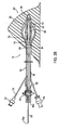
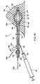
- FIG. 1 shows an exemplary embodiment of an expandable brachytherapy apparatus 10 that includes a proximal or tail portion 12, and a distal or therapy delivery portion 14, generally defining a longitudinal axis 16 extending therebetween.
- the distal portion 14 may be deployed or introduced within a target location of a patient's body, e.g., a tumor or cavity within a breast or other body structure (not shown), and the proximal portion 12 may extend from the distal portion 14, e.g., such that the proximal portion 12 protrudes at least partially outside of the body structure.
- the distal portion 14 generally includes an elongate core member 20, one or more catheters or other elongate members 30 adjacent the core member 20, and a balloon or other expandable member 50 (shown in cross-section only for clarity) at least partially surrounding the core member 20.
- the elongate members 30 may be movable between a collapsed configuration, as shown in FIG. 2A , e.g., for introduction through a tissue tract to a target location, and a fully deployed or expanded configuration, as shown in FIGS. 2B , e.g., for providing a three dimensional array of pathways at the target location, as described further below.
- the expandable member 50 may be expandable independently of the elongate members 30, e.g., to facilitate imaging, delineation of tissue surrounding a target treatment location, arid the like, also as described further below.
- the apparatus 10 may be part of a system, e.g., including a tubular delivery device, such as an introducer sheath, catheter, cannula, trocar, obturator, and/or needle (not shown), for introducing the apparatus 10 into a target location, one more sources of radiation, an aspiration catheter, and/or other components (also not shown), as described elsewhere herein and in the applications identified elsewhere herein.
- a tubular delivery device such as an introducer sheath, catheter, cannula, trocar, obturator, and/or needle (not shown)
- the core member 20 includes a proximal end 22 and a distal end 24 terminating in a distal tip 25, a distal hub 26 coupled to the distal tip 25, and a proximal hub 60 movable relative to the core member 20.
- the core member 20 may include a source lumen therein, e.g., extending from an opening 22a in the proximal end 22 to the distal end 24.
- the elongate members 30 extend generally axially adjacent the core member 20 in the collapsed configuration, e.g., between the proximal and distal hubs 60, 26.
- elongate members 30 are provided that include proximal ends 32 coupled to the proximal hub 60, distal ends 34 coupled to the distal hub 26, and expandable intermediate portions 35 adjacent the core member 20.
- the elongate members 30 may be offset circumferentially from one another about the longitudinal axis 16, e.g., about sixty degrees (60°).
- the elongate members 30 extend substantially axially along the core member 20 in the collapsed configuration and may bow or curve radially outwardly away from the core member 20 in the expanded configuration.
- elongate members 30 may be provided, e.g., three, four, five, seven, eight, or more (not shown), with the elongate members 30 offset radially relative to one another, e.g., distributed substantially evenly about the perimeter of the core member 20.
- the distal hub 26 may be formed from one or more components integrally molded, machined, or otherwise formed together from a single piece, or as separate components that are attached together.
- the distal ends 34 of the elongate members 30 may be received within and/or otherwise secured to the distal hub 26, e.g., by bonding with adhesive, sonic welding, fusing, mating connectors, and the like.
- the distal hub 26 may provide a rounded and/or tapered distal tip for the apparatus 10, e.g., to facilitate substantially atraumatic introduction into a patient's body.
- the distal hub 26 may include a pointed or other sharpened distal tip (not shown) for facilitating advancing the apparatus 10 directly through tissue, e.g., by dissection or puncture through tissue between the patient's skin and a target location.
- the distal hub 26 (and/or other components of the apparatus 10) may include radiopaque material, echogenic material, and the like to facilitate monitoring the distal hub 26 (and/or the apparatus 10) using external imaging, such as ultrasound, CT scanning or other x-ray imaging, and the like.
- the proximal hub 60 may be provided from one or more pieces, e.g., that may be slidably mounted around the core member 20 and coupled to the proximal ends 32 of the elongate members 30.
- the proximal hub 60 may include an annular collar that includes nipples or passages (not shown) for receiving the proximal ends 32 of the elongate members 30 to substantially permanently attach the proximal ends 32 to the proximal hub 60, e.g., by interference fit.
- the proximal ends 32 may be attached to the proximal hub 60 by bonding with adhesives, sonic welding, fusing, cooperating connectors, and the like.
- the proximal hub 60 may be formed from separate components (not shown) that may be attached together around the core member 20, e.g., using an interference fit, cooperating connectors, bonding using adhesive, sonic welding, and the like.
- the elongate members 30 may be elongate, fixed length tubular members or "catheters,” each including a proximal end 32, a distal end 34, and a lumen (not shown) extending therebetween, e.g., along the expandable intermediate portion 35 that extends along the core member 20.
- the proximal ends 32 may be received in, through, and/or otherwise coupled to the proximal hub 60, e.g., as described elsewhere herein.
- the elongate members 30 may include individual catheter tubes 30 coupled to respective struts or other supports 40.
- the supports 40 may be elongate wires, strips of material, and the like, e.g., made from metal, such as stainless steel or Nitinol, plastic, or composite material, that may be elastically deflected during use of the apparatus 10, e.g., when the distal portion 14 is directed between the collapsed and expanded configurations.
- the supports 40 include a circumferential or transverse "width” and a radial "thickness,” e.g., having a rectangular or elliptical cross-section to cause preferential bending of the supports 40 radially outwardly into an arcuate shape that bows radially outwardly from the proximal and distal hubs 60, 26.
- the supports 40 may have a substantially homogeneous cross-section along their lengths or may have varying cross-sections (not shown), e.g., if desired to vary the rigidity and/or bias of the elongate members 30 using the supports 40.
- the supports 40 may extend at least partially along the intermediate portion 35 of the elongate members 30.
- the proximal ends 42 of the supports 40 may be attached or secured to the proximal hub 60 and/or the proximal ends 32 of the elongate members 30, and the distal ends 44 may be attached or secured to distal hub 26 and/or the distal ends 34 of the elongate members 30.
- the distal ends 44 may be integrally formed with a sleeve or collar (not shown) that may be received within, around, and/or otherwise secured to the distal hub 26, similar to the embodiments described in application Serial No. 11/868,483, filed October 6, 2007 , published as U.S. Publication No. 2008/0091055 .
- proximal ends 42 may include connectors (not shown) that may be interlocked with one another and/or the proximal hub 60.
- the proximal ends 42 may be integrally formed with a collar or sleeve (not shown), similar to the distal ends 44.
- the supports 40 may be oriented such that their major dimension or width is disposed generally circumferentially relative to the core member 20 and their minor dimension or thickness is disposed generally radially.
- the supports 40 may be attached or otherwise secured to the elongate members 30 at one or more locations along their lengths, e.g., using shrink tubing, bonding with adhesive, sonic welding, and the like.
- heat shrink tubing (not shown) may be provided at one or more locations along the length of the elongate members 30 between the proximal and distal ends 32, 34 to couple movement of the elongate members 30 to the supports 40, e.g., as disclosed in application Serial No. 12/277,286, filed November 24, 2008 , published as U.S. Publication No. 2009/0156882 .
- the supports 40 may be provided within an additional lumen (not shown) within the elongate members 30, similar to embodiments disclosed in the applications identified elsewhere herein.
- the supports 40 may be eliminated.
- the elongate members 30 themselves may be configured, e.g., may have asymmetrical cross-sections (not shown) providing a moment of inertia that biases the elongate members 30 to expand radially outwardly towards a predetermined arcuate shape, e.g., while minimizing lateral movement.
- the supports 40 may provide shielding, in addition to or instead of supporting the elongate members 30, also as disclosed in the applications identified elsewhere herein.
- tubular extensions 36 may be coupled to the proximal hub 60 and/or coupled directly to the proximal ends 32 of the elongate members 30, e.g., extending proximally from the proximal hub 60 to at least partially define the proximal portion 12 of the apparatus 10.
- the tubular extensions 36 may be received in passages or over nipples (not shown) on the proximal hub 60 similar to the proximal ends 32 of the elongate members 30 such that lumens of the tubular extensions 36 communicate with lumens of the respective elongate members 30.
- each tubular extension 36 includes an opening 36a providing access into a respective source lumen, e.g., through the tubular extension 36 and into a respective elongate member 30, for receiving a radiation source, as described elsewhere herein.
- the tubular extensions 36 may be formed as an integral part of the elongate members 30, e.g., as a continuous extrusion, molding, and the like, such that the elongate members 30 extend continuously from the openings 33a to the distal ends 34.
- the tubular extensions 36 may remain substantially free relative to one another or may be at least partially constrained relative to one another.
- the tubular extensions 36 may extend substantially parallel to the longitudinal axis 16 along the core member 20 yet be sufficiently flexible to directed away from the core member 20, if desired during use.
- the tubular extensions 36 may pass through or be captured by a collar or other structure 37 on the proximal portion 12 of the apparatus, thereby keeping the tubular extensions 36 together, organized, and/or otherwise limiting relative movement of the tubular extensions 36, similar to embodiments in the applications identified elsewhere herein.
- the collar 37 may be fixed axially relative to the tubular extensions 36 or may be slidable along the tubular extensions 36, if desired.
- the collar 37 may be include numbers or other indicia (not shown) to identify respective openings 36a, tubular extensions 36, and/or source lumens during use.
- the tubular extensions 36 may be flexible, e.g., to allow the tubular extensions 36 to be curved or otherwise bent individually and/or together.
- the proximal portion 12 of the apparatus 10 may be easily bent, e.g., to accommodate securing the proximal portion 12 to a patient, for example, to the patient's skin adjacent a tract communicating with a treatment site within which the distal portion 14 has been introduced.
- the tubular extensions 36 may include one or more features, such as those disclosed in the applications identified elsewhere herein, to enhance flexibility and/or bending of the tubular extensions 36 to minimize a profile of the proximal portion 12 of the apparatus 10.
- the core member 20 may include one or more regions between the proximal and distal ends 22, 24 constructed from different materials and/or methods, e.g., to provide desired flexibility or rigidity for the proximal and distal portions 12, 14 of the apparatus 10.
- the distal end 24 may include one or more substantially rigid tubular bodies, e.g., extending at least between the proximal and distal hubs 60, 26 to maintain the relative position of the proximal and distal hubs 60, 26 and/or provide sufficient support for the elongate members 30 as they are expanded and/or collapsed.
- the proximal end 22 may include one or more semi-rigid or substantially flexible tubular members, e.g., similar to the extensions 36, to allow the proximal end 22 to be bent, folded, or otherwise directed against a patient's skin, e.g., while the distal end 24 is positioned within a target tissue region, as described elsewhere herein.
- an actuator member 62 may extend proximally from the proximal hub 60 for controlling movement of the proximal hub 60 from the proximal portion 12 of the apparatus 10.
- the actuator member 62 includes an elongate sleeve or tubular body including a proximal end 64 adjacent the proximal end 22 of the core member 20 and a distal end 66 coupled to the distal end 14 of the core member 20 and/or the proximal hub 60.
- the sleeve 62 may be movably disposed around the proximal end 22 of the core member 20 such that the sleeve 62 may be rotated and/or directed axially to move the proximal hub 60 to expand and/or collapse the elongate members 30, as described further below.
- the distal end 24 of the core member 20 may include a pair of telescoping tubes (not shown) extending between the proximal and distal hubs 60, 26 such that rotation of the tubes relative to one another cause the proximal and/or distal hubs 60, 26 to move axially towards or away from one another, e.g., similar to the embodiments described in the applications identified elsewhere herein.
- the actuator member 62 may be coupled to one of the telescoping tubes (not shown) such that subsequent rotation of the actuator member 62 causes the telescoping tube to rotate relative to the other telescoping tube, thereby directing the proximal hub 60 axially towards or away from the distal hub 26.
- the actuator member 62 may be coupled to the proximal hub 60, and the actuator member 62 and proximal hub 60 may be movable axially relative to the core member 20, e.g., similar to embodiments disclosed in application Serial Nos. 12/727,209, filed March 18, 2010 and published as U.S. Pub. No.2011/ 0230700 , and 12/841,111, filed July 21, 2010 .
- the actuator member 62 may be directed axially (distally or proximally without rotation) to direct the proximal hub 60 axially relative to the distal hub 26 to expand and collapsed the elongate members 30.
- the actuator member 62 may be removable from the apparatus 10.
- the distal end 66 of the actuator member may be releasably coupled to the core member 20 and/or the proximal hub 60, e.g., by mating threads, detents, male-and-female keyed connectors, and/or other features (not shown).
- the actuator member 62 may provided separately from the rest of the apparatus 10 or may already be coupled to the core member 20. If separate, before use, the actuator member 62 may be inserted between the tubular extensions 36 and over the proximal end 22 of the core member 20 until the distal end 66 is disposed adjacent the proximal hub 60.
- Connector(s) on the distal end 66 and the proximal hub 60 or one of the telescoping tubes may then be engaged to couple subsequent movement (e.g., rotation, linearly axial movement) of the proximal hub 60 to the actuator member 62 in preparation for use.
- the apparatus 10 also includes a balloon, impermeable membrane, or other expandable member 50 on the distal portion 14, extending at least partially between the proximal and distal hubs 60, 26.
- the expandable member 50 may be disposed between the elongate members 30 and the core member 20, e.g., such that the elongate members 30 extend along or around an outer surface of the expandable member 50.
- the balloon 50 may be disposed around the elongate members 30 (not shown), e.g., similar to embodiments in the applications identified elsewhere herein.
- the expandable member 50 includes a distal end 54 coupled to the core member 20, e.g., immediately adjacent the distal hub 26, or alternatively coupled directly to the distal hub 26, and a proximal end 52 coupled to the core member 20 at a predetermined distance proximal to the distal end 54.
- the proximal end 52 of the expandable member 50 may be attached at a predetermined location on the core member 20 such that the proximal end 52 is disposed adjacent the proximal hub 60 and/or the proximal ends 32 of the elongate members 30 when the proximal hub 60 is advanced to direct the elongate members 30 to the expanded configuration.
- the proximal end 52 of the expandable member 50 may be attached or otherwise coupled to the proximal hub 60 (not shown), e.g., such that the length of the expandable member 50 changes as the proximal hub 60 is directed axially along the core member 20.
- the expandable member 50 may be formed from an annular membrane or other balloon structure and the proximal and distal ends 52, 54 of the balloon 50 may be attached to the core member 20 (or other component of the apparatus 10), e.g., by bonding with adhesive, sonic welding, fusing, overlying bands or collars, and the like.
- the proximal and distal ends 52, 54 may provide a substantially fluid tight seal to allow inflation media to be introduced into an interior of the balloon 50, i.e., between the balloon wall and the core member 20, to expand the balloon 50.
- the balloon 50 may be formed from substantially flexible or compliant material, e.g., such that the size of the balloon 50 is proportional to the amount of inflation media introduced into the interior of the balloon 50.
- the balloon 50 may be formed from non-compliant material, e.g., such that the balloon 50 may be expanded to a predetermined size and/or shape once sufficient fluid is introduced into the interior of the balloon 50 without substantially expanding further (until a rupture pressure is achieved within the balloon interior).
- the apparatus 10 may include an inflation lumen 56 that extends at least partially between the proximal and distal portions 12, 14 thereof and communicates with the interior of the expandable member 50 for delivering inflation media into and/or evacuating inflation media from within the interior of the balloon 150.
- the inflation lumen 56 may be a separate tubular member from the tubular extensions 36 and proximal end 22 of the core member 20, e.g., also captured by the collar 37 to facilitate organization of the various tubular members.
- the inflation lumen 56 may include a loose proximal end 56a including a Luer connector or other fitting 58 and a distal end 56b coupled to the core member 20 and/or proximal hub 60.
- the distal end 56b may extend through the proximal hub 60 and into the core member 20, which may include a lumen and one or more ports (not shown) communicating with the interior of the expandable member 50.
- the distal end 56b may extend through the proximal hub 60 and into the proximal end 52 of the balloon 50, e.g., such that an opening in the distal end 56b communicates with the interior of the expandable member 50.
- the proximal end 52 of the expandable member 50 is coupled to the proximal hub 60
- the distal end 56b may be coupled to an opening through the proximal hub 60 that communicates with the interior of the expandable member 50.
- a syringe 59 or other source of inflation media and/or vacuum may be coupled to the fitting 58, e.g., for delivering or evacuating inflation media into/from the inflation lumen 56 via the fitting 58, i.e., for inflating or collapsing the expandable member 50, as described further below.
- the inflation media may be a liquid, gel, contrast material, or other flowable material that may be compatible with ultrasound, CT scanning, or other imaging.
- the inflation media may be a gas, such as air, nitrogen, carbon dioxide, and the like.
- the elongate members 30 are expendable independently of the expandable member 50.
- the actuator member 62 may be rotated in a first direction to direct the proximal hub 60 distally and expand the elongate members 30 from the collapsed configuration to the expanded configuration, as shown in FIG. 2B .
- the actuator member 62 may be secured in the distal position or simply removed, if desired, e.g., to prevent migration of the elongate members 30 towards the collapsed configuration.
- the expandable member 50 may be expanded, e.g., by coupling the syringe 59 to the fitting 58, and introducing inflation media into the interior of the expandable member 50 via the inflation lumen 56.
- the expandable member 50 contacts the elongate members 30, e.g., to press surrounding tissue outwardly, as described further below.
- the apparatus 10 may also include a working channel member 70 extending between the proximal and distal portions 12, 14 thereof.
- the working channel member 70 includes a proximal end 72 including a valve, connector, or other fitting 73, a distal end 74 including an outlet 75, and a lumen or other working channel (not shown) extending therebetween.
- the proximal end 72 may be captured by the collar 37 for organization but otherwise loose or free to be directed away from the tubular extensions 36 during use.
- the fitting 73 may include a valve (not shown) therein, which may substantially seal the lumen yet accommodate introduction of one or more instruments (not shown) into the lumen.
- the fitting 73 may include a Luer valve, one-way valve, or other hemostatic valve that may slidably received one or more instruments therethrough while preventing substantial leakage of fluid through the fitting 73 around the instrument(s).
- the fitting 73 may include a connector for positively engaging mating features on one or more instruments introduced into the fitting 73, e.g., to prevent the instrument(s) from moving once engaged, if desired during use.
- the distal end 74 of the working channel member 70 may extend through or otherwise along the proximal hub 60 such that the opening 75 is disposed adjacent the elongate members 30 and/or expandable member 50.
- the distal end 74 may be shaped, e.g., curved outwardly away from the core member 20, such that the distal end 74 does not interfere substantially with expansion of the expandable member 50 yet may place the opening 75 adjacent the outer surface of the expandable member 50.
- the distal end 74 may include a valve (not shown) therein in addition to or instead of providing a valve in the fitting 73, e.g., to prevent fluid from leaking substantially into the working channel, if desired.
- the apparatus 10 may be used for brachytherapy treatment within a tissue structure, for example, within a breast 90.
- the breast 90 may have a cavity (e.g., a lumpectomy cavity) 92 formed therein, e.g., by removal of cancerous tissue.
- an introducer sheath is used (not shown)
- the introducer sheath may be introduced into the cavity 92, as described in the applications identified elsewhere herein.
- a trocar also not shown
- the introducer sheath and trocar may be advanced directly through tissue, thereby creating a tract 94 communicating with the cavity 92.
- the tract 94 may be created in advance, e.g., using a needle or other device (not shown).
- the trocar may then be removed, leaving the introducer sheath to provide a path through the tissue of the breast 90 into the cavity 92.
- the inner surface of the introducer sheath may include lubricious material to facilitate introducing the apparatus 10 and/or other devices therethrough.
- the apparatus 10 may be provided initially with the proximal hub 60 and actuator member 62 in a proximal or first position, i.e., with the proximal and distal hubs 60, 26 spaced furthest apart, thereby providing the elongate members 30 in the collapsed condition.
- the apparatus 10 may be manufactured with the elongate members 30 biased to the expanded configuration, e.g., by the supports 40, and the elongate members 30 may be collapsed to the collapsed configuration, e.g., before packaging and/or shipment.
- the apparatus 10 may be packaged and/or shipped with the elongate members 30 in the expanded configuration.
- the actuator member 62 may be directed to collapse the elongate members 30 to the collapsed configuration. This alternative may be useful if the apparatus 10 may be stored for an extended time before use, e.g., to reduce the risk of the supports 40 losing some of their bias to the expanded configuration.
- the apparatus 10 may be inserted through the tract 94, e.g., through an introducer sheath (not shown), with the elongate members 30 in the collapsed configuration, e.g., until the distal hub 26 is disposed within the cavity 92.
- the apparatus 10 may be inserted directly through an existing incision without an introducer sheath, e.g., the incision used to perform the lumpectomy, or via a new incision created for delivering the apparatus 10.
- the apparatus 10 may be advanced directly through tissue, e.g., if the distal hub 26 includes a sharpened tip (not shown), as described in the applications identified elsewhere herein.
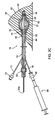
- the apparatus 10 may be positioned such that the distal hub 26 is placed in the far end of the cavity 92, as shown in FIG. 2A , e.g., such that the elongate members 30 (in the collapsed configuration) extend across and/or partially from the cavity 92, e.g., into the tract 94.
- the introducer sheath (if used) may be removed from around the apparatus 10. For example, if the introducer sheath includes a longitudinal slit or is otherwise separable, the introducer sheath may be pulled transversely away from the apparatus 10, thereby causing side edges defining the slit to separate and pass around the apparatus 10 (not shown). As shown in FIG.
- the distal portion 14 of the apparatus 10 is positioned within the cavity 92, with the proximal portion 12 extending from the cavity 92, through the tract 94, and/or otherwise out of the breast 90.
- the apparatus 10 is ready for expansion and delivery of radiation.
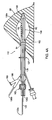
- the actuator member 62 may be manipulated to direct the proximal hub 60 distally relative to the distal hub 26, thereby causing the elongate members 30 to expand outwardly within the cavity 92.
- the actuator member 62 may be rotated to expand the elongate members 30 to the expanded configuration, which may lie within a range of diameters, e.g., depending on the size of the cavity 92 and/or the length and/or other configuration of the elongate members 30.
- the elongate members 30 may have sufficient bias to at least partially direct tissue surrounding the cavity outwardly and/or cause the tissue to invaginate between adjacent elongate members 30, as disclosed in the applications identified elsewhere herein.
- the elongate members 30 and/or the distal portion 14 may include one or more extensions, membranes, balloons, or other features to shape the cavity 92 in a desired manner, e.g., as described elsewhere herein and/or in the applications identified elsewhere herein.
- the elongate members 30 may have sufficient radial outward bias to maintain a desired maximum spacing between adjacent elongate members 30.
- the supports 40 may bias the elongate members 30 to be spaced substantially uniformly from one another about the circumference when the apparatus 10 is expanded.
- the maximum spacing of the supports 40, and consequently, the elongate members 30, may be not more than about 1.5 centimeters, e.g., at the midpoints of the supports 40.
- the expandable member 50 may be expanded, e.g., by coupling a syringe or other source of inflation media 59 to the fitting 58 and introducing inflation media into the interior of the expandable member 50.
- the inflation media may be compatible and/or enhance external imaging of the apparatus 10, cavity 92, and/or surrounding tissue.
- air may interfere with ultrasound imaging, and so the inflation media may be a liquid, gel, or other flowable material that is does not interference with such imaging.
- the expandable member 50 may be expanded until the expandable member 50 presses against or otherwise contacts the elongate members 30 and/or surrounding tissue.
- the expandable member 50 may be expanded sufficiently to further shape the cavity 92 and/or surrounding tissue in addition to any shaping achieved with the elongate members 30 alone, and/or to substantially fill any voids or gaps within the cavity 92.
- the expandable member 50 may be expanded until it is spaced slightly away from the elongate members 30, e.g., simply to prevent excess tissue from invaginating between the elongate members 30.
- external imaging may be utilized, such as ultrasound, CT, fluoroscopy, and the like, e.g., to facilitate dose planning.
- Dose planning may be accomplished using a variety of imaging methods (e.g., CT or ultrasound) and/or using dose planning software for either HDR or LDR applications.
- the timing and general scenario of the dose planning process is at the discretion of the clinical physicist/oncologist. For example, with the aid of imaging, both the target tissue region and the position of the elongate members 30 may be delineated.
- a dose plan may then be developed and, if desired, modified as configuration adjustments are made to the apparatus 10 and/or the elongate members 30.
- the elongate members 30, core member 20, expandable member 50, and/or other components of the apparatus 10 may include markers (not shown) to facilitate identifying the orientation of the apparatus 10 during dose planning, as described in the applications identified elsewhere herein.
- the expandable member 50 may be collapsed, e.g., by coupling a syringe or other source of vacuum (not shown) to the fitting 58 and evacuating the inflation media from the interior of the expandable member 50.
- the expandable member 50 may remain expanded, if desired, e.g., to substantially maintain the surrounding tissue in a defined position relative to the elongate members 30 and/or core member 20.
- the actuator member 62 may be removed to prevent undesired collapse or other movement of the elongate members 30 from the expanded configuration.
- One or more sources of radiation may be then directed into the elongate members 30 and/or core member 20, e.g., via the openings 36a and tubular extensions 36, and/or into the opening 22a in the proximal end 22 of the core member 20.
- the elongate members 30 and/or core member 20 may be sized and/or otherwise configured to receive commercially available HDR afterloader transfer tubes (not shown), such as those available from Varian and Nucletron.
- an HDR source may be introduced into a first elongate member 30, advanced to a first position, and maintained at the first position for a predetermined time.
- the HDR source may then be advanced and/or retracted to a second position, and maintained there for a predetermined time, etc.
- the HDR source may then be removed from the first elongate member 30, and then introduced into the other elongate member 30 (or sequentially into each elongate member if the apparatus 10 includes more than two elongate members, not shown), in a similar manner.
- a plurality of LDR sources may be delivered into the elongate members 30 and/or central catheter 20b, and remain indwelling for a predetermined time.
- individual pods or other radiation sources may be loaded into respective elongate members 30 and/or the core member 20 simultaneously or sequentially, thereby providing a three dimensional array of seeds or radiation sources that may remain in the target location for an extended period of time.
- the seeds may be spaced apart on each pod and/or may have different radioactive intensities, according to the dose plan.
- one or more radiation sources may be preloaded or secured within the elongate members 30 and/or core member 20 before introduction into the cavity.
- radiation may be delivered via the elongate members 30 and/or core member 20 according to a desired treatment plan, as described in the applications identified elsewhere herein.
- an aspiration catheter 80 may be provided that includes an elongate tubular catheter body 82 including a proximal end 84, a distal end 86 sized for introduction into the working channel member 70, and a lumen (not shown) extending therebetween.
- the proximal end 84 may be coupled to a syringe or other source of vacuum 80, and the distal end 86 may include one or more openings 88 communicating with the syringe 80 via the aspiration catheter lumen.
- the aspiration catheter 80 or another instrument may be provided for delivering material into the cavity 92, e.g., before, during, or after treatment(s).
- the distal end 86 of the aspiration catheter 80 may be introduced through the fitting 73 and working channel member 70 until the distal end 86 is advanced from the opening 75 and positioned within the cavity 92 adjacent the core member 20 and/or elongate members 30.
- the syringe 80 (or different syringes, not shown) may be actuated to deliver material into the cavity 92 and/or aspirate material from within the cavity 92.
- the aspiration catheter 80 may remain stationary during aspiration or may be manipulated to move the distal end 86 within the cavity 92 to facilitate aspiration or material therein.
- the aspiration catheter 80 may be removed from the working channel member 70.
- the working channel member 70 may include a valve, e.g., within the fitting 73, that may seal the working channel after the aspiration catheter 80 is removed. Radiation sources may then be delivered to the target treatment region, as described above.
- the apparatus 10 may be secured relative to the target tissue region to prevent subsequent migration.
- tape, an external collar, and/or other features may be used to secure the proximal portion 12 of the apparatus 10 extending from the breast 90, e.g., to the patient's skin.
- the elongate members 30 may sufficiently engage the tissue surrounding the cavity 92 in the expanded configuration to prevent substantial migration.
- the tubular extensions 36 and/or the proximal end 22 of the core member 20 may be folded or otherwise directed against the patient's skin where they exit the tract 94, e.g., between treatments, and taped or otherwise secured against the patient's skin.
- at least a portion of the proximal portion 12 of the apparatus 10, e.g., at least the actuator member 62, may be removable (not shown), e.g., to reduce the profile of the proximal portion 12 extending from the patient's body, as described in the applications identified elsewhere herein.
- the actuator member 62 may be reconnected to the apparatus 10 (if removed), and rotated to return the elongate members 30 back to the collapsed configuration. If the expandable member 50 remained expanded during treatment, the expandable member 50 may also be collapsed, e.g., before the elongate members 30, by coupling the syringe 59 or other source of vacuum to the fitting 58 and evacuating the fluid from within the expandable member 50. The apparatus 10 may then be removed from the breast 90 via the tract 94.
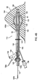
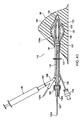
- FIGS. 3A-3D yet another exemplary embodiment of an expandable brachytherapy apparatus 110 is shown that includes a proximal or tail portion 112 and a distal or therapy delivery portion 114, generally defining a longitudinal axis 116 extending therebetween. Similar to the previous embodiment, the apparatus 110 includes an elongate core member 120 including proximal and distal ends 122, 124, a plurality of elongate members 130, a distal hub 126 coupled to the distal end 124, and a proximal hub 160 movable relative to the core member 120.
- a plurality of tubular extensions 136 may be coupled to the elongate members 130, and an actuator member 162 may be coupled to the core member 120 and/or proximal hub 160, similar to the previous embodiment.
- the apparatus 110 may include a balloon or other expandable member 150 on the distal portion 114, similar to the previous embodiment.
- one or more of the elongate members 130 may include an aspiration catheter or member for aspirating material from within a cavity 92, e.g., instead of the working channel member 70 and aspiration catheter 80 described above.
- all of the elongate members 130 may include a proximal end 132 coupled to the proximal hub 160, a distal end 134 coupled to the distal hub 126, and a lumen (not shown) extending therebetween, similar to the previous embodiment.
- one of the elongate members 130a may include aspiration features as well as providing a pathway for receiving a source of radiation.
- one of the elongate members 130a may be an aspiration catheter or other elongate tubular body 180 that includes multiple lumens 182 extending therethrough to provide both a source lumen and aspiration.
- the aspiration catheter 180 may include one or more aspiration lumens 182s and a central source lumen 182b extending therethrough, e.g., from a proximal housing 188 on the proximal portion 112 to the distal portion 114, possible to the distal hub 126.
- the source lumen 182b may be a central, e.g., circular cross-section, lumen and the aspiration lumen(s) 182a may include multiple lumens within the wall of the aspiration catheter 180 at least partially surrounding or otherwise adjacent the source lumen 182b.
- the aspiration lumen(s) 182a may include multiple lumens within the wall of the aspiration catheter 180 at least partially surrounding or otherwise adjacent the source lumen 182b.
- side-by-side lumens or other configurations may be provided rather than concentric lumens, as shown.
- the aspiration catheter 180 may have a substantially uniform construction between the proximal and distal hubs 160, 126 and, optionally, extending to the housing 188 on the proximal portion.
- the aspiration catheter 180 may be formed as a substantially continuous extrusion or molded tubular body, as desired during manufacturing.
- the construction of the aspiration catheter 180 may vary between the proximal and distal portions 112, 114 of the apparatus 110, e.g., to provide desired flexibility and/or rigidity.
- One or more ports 184 may be provided on the aspiration catheter 180a between the proximal and distal hubs 160, 126, e.g., to allow delivery of material into a cavity or other region adjacent the elongate members 130 and/or aspiration of material from the cavity.
- a plurality of ports 184 may be provided that are spaced apart from one another between the proximal and distal hubs 160, 126.
- the housing 188 on the aspiration catheter 180 may have a bifurcated shape, e.g., a "Y" or "T” shape to separate the aspiration lumen(s) 182a and the source lumen 182b.
- the housing 188 may include a fitting 189, similar to fitting 73, for coupling a syringe 89 or other source of material and/or vacuum to the housing 189, e.g., as shown in FIG. 4D .
- the fitting 189 may communicate with the aspiration lumen(s) 182a and, optionally, include a valve (not shown), e.g., a Luer valve, for providing a substantially fluid tight seal when the syringe 89 is not coupled to the fitting 189.
- a tubular extension including an opening 136a may extend from the housing 188 that communicates with the source lumen 182b, e.g., for receiving a source of radiation similar to the tubular extensions 136.
- the elongate member 130a may include a support member 140 extending at least partially along a length of the aspiration catheter 180, e.g., between the proximal and distal hubs 160, 136, similar to the previous embodiment.
- the support member 140 may be coupled to the aspiration catheter 180 by one or more sections of heat shrink tubing 186 and the like, similar to the previous embodiment and embodiments in the applications identified elsewhere herein.
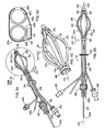
- an apparatus 210 may be provided that includes an aspiration member 130a including an aspiration catheter 280a separate from a source lumen catheter 280b.
- the aspiration catheter 280a may include an aspiration lumen 282a and the source lumen catheter 280b may include a source lumen 282b.
- the aspiration and source lumen catheters 280a, 280b may be formed separately, e.g., by extrusion, molding, and the like, and secured together, e.g., by one or more sections of heat shrink tubing 286 and the like.
- a support member 244 may also be secured to the aspiration and source lumen catheters 280a, 280b, e.g., between the proximal and distal hubs 260, 226, by the heat shrink tubing 286.
- the aspiration and source lumen catheters 280a, 280b may be attached together, e.g., by bonding with adhesive, fusing, sonic welding, and the like, or may be formed together, e.g., as a coextrusion and the like.
- the apparatus 110 of FIGS. 3A-3D may be used for brachytherapy treatment within a tissue structure, for example, within a breast 90 (the apparatus 210 of FIGS. 5A-5D may be used in a similar manner for brachytherapy treatment within a tissue structure, for example, within a breast 90, as shown in FIGS. 6A-6D ).
- the apparatus 110 may be provided initially with the proximal hub 160 and actuator member 162 in a proximal or first position, thereby providing the elongate members 130 in the collapsed condition.
- the apparatus 110 may be inserted through the tract 94, e.g., through an introducer sheath (not shown), with the elongate members 130 in the collapsed configuration, e.g., until the distal hub 126 is disposed within the cavity 192.
- the apparatus 110 may be positioned such that the distal hub 126 is placed in the far end of the cavity 92, as shown in FIG. 4A , e.g., such that the elongate members 130 (in the collapsed configuration) extend across and/or partially from the cavity 92, e.g., into the tract 94.
- the introducer sheath if used may be removed from around the apparatus 110.
- the distal portion 114 of the apparatus 110 is positioned within the cavity 92, with the proximal portion 112 extending from the cavity 92, through the tract 94, and/or otherwise out of the breast 90.
- the actuator member 162 may be manipulated to direct the proximal hub 160 distally relative to the distal hub 126, thereby causing the elongate members 130 (including the elongate member 130a including the aspiration catheter 180) to expand outwardly within the cavity 92.
- the actuator member 162 may be rotated in a first direction to expand the elongate members 130 to the expanded configuration.
- the elongate members 130 may have sufficient bias to at least partially direct tissue surrounding the cavity outwardly and/or cause the tissue to invaginate between adjacent elongate members 130, similar to the methods described elsewhere herein.
- the expandable member 150 may be expanded, e.g., by coupling a syringe or other source of inflation media 59 to the fitting 158 and introducing inflation media into the interior of the expandable member 150. Similar to the other embodiments herein, the inflation media may be compatible and/or enhance external imaging of the apparatus 110, cavity 92, and/or surrounding tissue.
- the expandable member 150 may be expanded until the expandable member 150 presses against or otherwise contacts the elongate members 130 and/or surrounding tissue.
- the expandable member 150 may be expanded sufficiently to further shape the cavity 92 and/or surrounding tissue in addition to any shaping achieved with the elongate members 130 alone, and/or to substantially fill any voids or gaps within the cavity 92.
- the expandable member 150 may be expanded until it is spaced slightly away from the elongate members 130, e.g., simply to prevent excess tissue from invaginating between the elongate members 130.
- external imaging may be utilized, such as ultrasound, CT, fluoroscopy, and the like, e.g., to facilitate dose planning.
- both the target tissue region and the position of the elongate members 130 may be delineated.
- a dose plan may then be developed and, if desired, modified as configuration adjustments are made to the apparatus 110 and/or the elongate members 130.
- the elongate members 130, core member 120, expandable member 150, and/or other components of the apparatus 110 may include markers (not shown) to facilitate identifying the orientation of the apparatus 110 during dose planning, as described elsewhere herein.
- the expandable member 150 may be collapsed, e.g., by coupling a syringe or other source of vacuum (not shown) to the fitting 158 and evacuating the inflation media from the interior of the expandable member 150.
- the expandable member 150 may remain expanded, if desired, e.g., to substantially maintain the surrounding tissue in a defined position relative to the elongate members 130 and/or core member 120.
- the actuator member 162 may be removed to prevent undesired collapse or other movement of the elongate members 130 from the expanded configuration.
- One or more sources of radiation may be then directed into the elongate members 130 and/or core member 120, e.g., via the openings 136a and tubular extensions 136, and/or into the opening 122a in the proximal end 122 of the core member 120, similar to other embodiments herein.
- the apparatus 110 may be secured relative to the cavity 92 and/or breast 90, e.g. to prevent subsequent migration.
- the elongate members 130 may sufficiently engage the tissue surrounding the cavity 92 in the expanded configuration to prevent substantial migration. If the apparatus 110 is to remain within the target tissue region for an extended period of time, the tubular extensions 136 and/or the proximal end 122 of the core member 120 may be folded or otherwise directed against the patient's skin where they exit the tract 94, e.g., between treatments, and taped or otherwise secured against the patient's skin.
- proximal portion 112 of the apparatus 110 may be removable (not shown), e.g., to reduce the profile of the proximal portion 112 extending from the patient's body, as described elsewhere herein.
- the actuator member 162 may be reconnected to the apparatus 110 (if removed), and rotated, e.g., in a second opposite direction, to return the elongate members 130 back to the collapsed configuration. If the expandable member 150 remained expanded during treatment, the expandable member 150 may also be collapsed, e.g., before the elongate members 130, by coupling the syringe 59 or other source of vacuum to the fitting 158 and evacuating the fluid from within the expandable member 150. The apparatus 110 may then be removed from the breast 90 via the tract 94.
- the apparatus described herein may permit brachytherapy devices (or other radiation sources), via a single point of entry, to deliver radiation to the tissue surrounding a cavity from a position within the cavity.
- the intracavitary apparatus and systems described herein may permit substantial fixation of one or more radiation sources relative to the target tissue region surrounding the cavity.
- the surrounding tissue may invaginate sufficiently around the devices to ensure adequate fixation and/or sufficient depth of penetration of the desired radiation dose to the tissue adjacent the lumpectomy cavity throughout the implantation period.
- the desired dose delivery to specific tissue may be achieved over the course of brachytherapy treatment.
- irradiation of unintended tissue e.g., due to movement of the device relative to the surrounding tissue, may be minimized.
- brachytherapy devices described herein may be implanted into (and/or around) a tumor before surgical excision (neoadjuvantly), and then subsequently removed before or at the time of surgery. Such treatments may shrink or even destroy the tumor.
- the apparatus described herein may be used to deliver brachytherapy after surgically removing tumor tissue to treat surrounding tissue postoperatively (post-lumpectomy in breast).
- brachytherapy apparatus described and illustrated herein may supplement or reduce the need for conventional treatment options, e.g., tumor excision, full field external beam radiation therapy (EBRT), and chemotherapy.
- EBRT full field external beam radiation therapy
- the methods described herein may be performed adjuvantly with these and other treatments, e.g., with chemotherapy, EBRT.
- Treatment in accordance with the present invention may also avoid some of the disadvantages of HDR treatment, e.g., high activity, exposure of unintended tissue, potentially bulky and protruding catheters, and/or the need for numerous patient visits to receive treatment.
- the apparatus described herein may be used to perform HDR treatment, e.g., by delivering one or more HDR radiation sources along pathways of the devices in accordance with known HDR dose plans.
- a HDR radiation source e.g., an Iridium tipped afterloader cable from Varian Medical Systems, Inc., or a small diameter x-ray source, such as those disclosed in U.S. Publication No.
- 2005/0061533A1 may be advanced through any of the core members described herein, with the expandable devices opening a cavity to facilitate delivering radiation more evenly to the tissue surrounding the cavity.
- the core member may shield the radiation source to direct radiation from the radiation source towards a desired portion of the surrounding tissue.
- the brachytherapy devices described herein are also substantially flexible, in comparison to conventional HDR catheters, such that they may be placed in either a straight or curvilinear (e.g., curved or spiral) fashion. Such flexibility may permit implantation of radiation sources (e.g., seeds) in configurations and locations that otherwise may be considered inaccessible.
- radiation sources e.g., seeds
- Apparatus and methods of the present invention may also potentially achieve desired dosage with relatively few catheters.
- the apparatus and methods described herein potentially may obtain desired dose delivery levels with fewer catheters per target than is typically utilized with conventional HDR methods.
- the devices described herein may still be implanted with the use of conventional imaging methods (e.g. stereotactic X-ray, ultrasound, CT).
- Apparatus and methods of the present invention may also provide other benefits to the patient. For example, potentially less skin damage and discomfort may result from smaller and more flexible catheter insertions. Further, the small flexible tail portions, once in their proper position, may be trimmed short, but may also be folded and taped against the skin, unlike rigid HDR catheters. Thus, the patient may have less discomfort over the course of treatment and potentially improved post-procedural cosmesis. Further, for example, apparatus and techniques in accordance with the present invention may potentially result in reduced side effects as compared to other treatments, e.g., EBRT and chemo, and may require fewer hospital visits over the course of the treatment regimen as compared to, for example, current HDR brachytherapy.
- other treatments e.g., EBRT and chemo
- the brachytherapy delivery systems described herein may provide a standardized dose of radiation based upon lesion size.
- the need for extensive dose calculating and mapping systems may potentially be reduced or eliminated with certain cancers (e.g., breast).
- brachytherapy apparatus Additional information on brachytherapy apparatus that include features that may be incorporated into the embodiments described herein and on methods for using such apparatus may be found in co-pending application Serial Nos. 10/658,518, filed September 9, 2003 , now U.S. Patent No. 7,601,113 , 11/276,851, filed March 16,2006 , published as U.S. Publication No. 2007/ 0106108 , 60/803,828, filed June 2, 2006 , 11/757,231, filed June 1,2007 , published as U.S. Publication No. 2008/0221384 , 11/868,483, filed October 6, 2007 , published as U.S. Publication No. 2008/0091055 , and 12/543, 469, filed August 18, 2009 , published as U.S. Publication No. 2010/ 0048967 .
Description
- The present invention relates generally to apparatus and systems for providing brachytherapy to a human or other mammalian body, and more particularly to expandable apparatus for performing brachytherapy treatment within tissue, e.g., within breast tissue and/or within a body cavity.
- Brachytherapy is a type of radiation therapy used to treat malignant tumors, such as cancer of the breast or prostate. In general, brachytherapy involves positioning a radiation source directly into target tissue, e.g., a tumor and/or tissue surrounding a cavity or void, which may contain potentially cancerous cells (such as a cavity or void created by removing a tumor).
-
WO2008/008089 discloses devices and methods for asymmetrical irradiation at a body cavity or site, such as after removal of tissue, e.g. biopsy or cancer. One device includes a lumen which is off-set or off-settable from a longitudinal axis to increase the intensity of radiation received from a radiation source by a first tissue portion surrounding the body cavity and to reduce or minimize radiation received by a second tissue portion (e.g. healthy tissue) surrounding the body cavity. -
US2008/221384 discloses apparatus for delivering brachytherapy to a target tissue region that includes an elongate body including a proximal end, a distal end sized for introduction into a tissue tract and carrying a plurality of elongate members including pathways for receiving a source of radiation. The elongate members are movable between collapsed and expanded configurations. During use, a tract is created through tissue, and the elongate body carrying the elongate members is advanced through the tract into a target location with the elongate members in the collapsed configuration. The elongate members are directed to the expanded configuration at the target location, and radiation is delivered to treat tissue at the target location, e.g., by introducing one or more radiation sources along the pathways. - Brachytherapy is often divided into two categories: high dose rate (HDR) and low dose rate (LDR) brachytherapy. In HDR brachytherapy, a high activity radiation source is placed into target tissue, often via a previously implanted catheter, for a short period of time, e.g., lasting from several seconds to a few minutes. In LDR brachytherapy, a low activity radiation source is placed into the target tissue for a longer, sometimes indefinite, period of time.
- Both forms of brachytherapy have advantages. For instance, HDR brachytherapy provides higher radiation levels delivered over a shorter dose delivery period, while LDR brachytherapy utilizes relatively lower activity radiation sources. The energy field of the LDR radiation source results in a measured and localized dose of radiation delivered to target tissue, e.g., a tumor, gland, or other tissue surrounding a cavity or void. However, the energy field thereafter decays to avoid excessive exposure of nearby healthy tissue. Due in part to the lower activity of LDR radiation sources, exposure precautions for LDR brachytherapy, e.g., for healthcare workers, may be less stringent than those for HDR brachytherapy. For patients, the relatively longer implantation period associated with LDR brachytherapy may result in fewer visits to a healthcare facility over the course of radiation treatment, as compared to HDR brachytherapy where patients must return to the healthcare facility for each fraction of radiation delivered, which, for breast brachytherapy, may typically include eight to ten (8-10) fractions.
- While effective, current brachytherapy implementations have potential drawbacks. For example, LDR seeds are typically left indwelling and free floating within the target tissue and are, therefore, susceptible to migration. Moreover, once implanted, LDR seeds are generally not considered removable or repositionable. Yet another issue with conventional LDR brachytherapy techniques is that they may require the radioactive seeds to be manipulated individually at the time of implantation, which may be a time-consuming process. Moreover, conventional LDR delivery needles are generally limited to delivering the seeds linearly (along a relatively straight line). Thus, to achieve a desired therapy profile, numerous implants (e.g., including about 50-100 seeds, as are common with prostate brachytherapy) are often required, in conjunction with potentially complex dose distribution and mapping techniques and equipment.
- According to the present invention there is provided a brachytherapy treatment apparatus as claimed in the appended claims.
- The present invention is generally directed to an apparatus for delivering brachytherapy to a localized target tissue region. While potentially useful in treating most any area of the body, an exemplary application is treating breast tissue, e.g., breast tumors or lumpectomy cavities. For example, the apparatus may be used to place and remove a localized radiation source for both neoadjuvant and post-excisional treatment.
- In accordance with one embodiment, a system is provided for delivering one or more therapeutic elements (e.g., radiation sources) relative to a target tissue region. Once delivered, the radiation sources may be either immediately withdrawn (e.g., in HDR applications), or left in place, e.g., implanted, for a defined period of time (e.g., in LDR applications). In either instance, the radiation sources may deliver therapy to the target tissue region in accordance with a predefined therapy profile.
- As used herein, "radiation source" or "source of radiation" may include any therapeutic element operable to deliver a dose of radiation. For example, the radiation source may be one or more radioactive seeds or, alternatively, one or more LDR or HDR wire elements (e.g., Iridium wire), e.g., as disclosed in the applications identified elsewhere herein.
- The term "implantable," as used herein, indicates the capability of a device to be inserted into the body and then maintained in a relatively fixed or static position within the surrounding tissue for an extended period of time, e.g., an hour or more and/or several hours or more, including several days or more.
- Furthermore, "target tissue region," as used herein, may include any portion of a human (or other mammalian) body that has been identified to benefit from radiation therapy. For example, the target tissue region may be a tumor or lesion itself, tissue proximate or surrounding the tumor, or a cavity region created by tumor excision (such as the surrounding tissue or cavity associated with a lumpectomy cavity of the breast).
- It should be noted that the apparatus and systems described herein may be used for LDR or HDR brachytherapy, as described elsewhere herein and in the applications identified elsewhere herein. Moreover, while described herein with respect to brachytherapy, the apparatus and systems may apply to other therapy regimens that benefit from the removable implantation of therapy-delivering elements. In an exemplary application, the apparatus and systems are described herein for treating breast cancer. However, it will be appreciated that the apparatus and systems described herein may be used for treating other cancers or conditions that may benefit from brachytherapy treatment.
- A brachytherapy treatment apparatus is described that includes an elongate body including a proximal portion and a distal portion sized for introduction into a tract through tissue. One or more tubular or elongate members may be provided on the distal portion including lumen(s) or other pathway(s) for receiving a source of radiation therealong, the elongate member(s) being movable between a collapsed configuration for introduction through a tissue tract to a target location and an expanded configuration. A source of radiation may be introduceable along the pathway(s) for delivering radiation to the target location.
- The apparatus includes an elongate core member including proximal and distal ends, a proximal portion, and a distal portion configured for introduction into a tract through tissue and terminating in a distal tip. A plurality of catheters or other elongate members may be provided on at least the distal portion adjacent the core member. Each elongate member may include a distal end coupled to the core member distal end, a proximal end movable relative to the core member, and a pathway extending between the elongate member proximal and distal ends for receiving a source of radiation therealong. Optionally, the core member may also include a source lumen or other pathway for receiving a source of radiation therealong.
- The elongate member proximal ends may be movable relative to the distal ends for expanding the elongate members from a collapsed configuration to an expanded configuration such that the elongate members are directed radially outwardly away from the distal portion of the core member. For example, the apparatus may include a proximal hub movably mounted on the core member and the proximal ends of the elongate members may be coupled to the proximal hub such that an actuator member extending proximally from the proximal hub may be used for actuating the proximal hub to direct the elongate members from the collapsed configuration to the expanded configuration.
- In addition, the apparatus includes an expandable member including a proximal end coupled to the core member adjacent the elongate member proximal ends and a distal end coupled to the distal tip of the core member such that the expandable member surrounds the distal portion of the core member. For example, the proximal and distal ends of the expandable member may be coupled to the core member at spaced apart locations or to proximal and distal hubs on the core member such that an interior of the expandable member is substantially sealed to allow introduction of inflation media therein to expand the expandable member. In an exemplary embodiment, the expandable member may be a balloon or other impermeable membrane and the apparatus may include an inflation lumen extending distally from the core member proximal end and communicating with the interior of the expandable member for delivering inflation media into and withdrawing inflation media from the interior for expanding and collapsing the expandable member.
- The elongate members extend along an outer surface of the expandable member in the collapsed configuration. The expandable member is expandable independently of the elongate members such that the elongate members may be expanded away from the expandable member before the expandable member is expanded. Thus, the expandable member may be expanded after expanding the elongate members such that the expandable member expands outwardly towards and contacts the expanded elongate members, e.g., to facilitate imaging and/or other aspects of a treatment procedure.
- Optionally, the apparatus may also include a working channel member extending between the proximal and distal portions of the core member. The working channel member may include a lumen extending therethrough, for example, for directing one or more instruments into a cavity or other region adjacent the distal portion, e.g., outside the expandable member. If desired, the working channel member may include a valve for selectively sealing the lumen, e.g., to prevent leakage of fluid from the cavity or region while accommodating introducing the one or more instruments therethrough.
- In an exemplary embodiment, the one or more instruments may include an aspiration catheter for aspirating material from within the cavity or other region adjacent the distal portion. For example, the aspiration catheter may include a proximal end, a distal end sized for introduction through the working channel, and a lumen extending therebetween. The aspiration catheter proximal end may be coupled to a vacuum source for aspirating material into the aspiration catheter lumen via an opening in the aspiration catheter distal end.
- In another option, at least one of the elongate members may include an aspiration member including one or more ports adjacent the distal portion communicating with an aspiration lumen extending to a proximal end of the aspiration member. A vacuum source may be coupled to the proximal end of the aspiration member for aspirating material into the aspiration lumen via the one or more ports. In one embodiment, the aspiration member may be disposed adjacent a tubular member including a source lumen or other pathway for receiving a source of radiation therealong. In another embodiment, the aspiration member may also include a source lumen, in addition to the aspiration lumen, e.g., providing a pathway for receiving a source of radiation therealong.
- The brachytherapy treatment apparatus includes an elongate core member including proximal and distal ends, a proximal portion, and a distal portion configured for introduction into a tract through tissue and terminating in a distal tip. A plurality of catheters or other elongate members may be provided on at least the distal portion adjacent the core member. Each elongate member may include a distal end coupled to the core member distal end, a proximal end movable relative to the core member, and a pathway extending between the elongate member proximal and distal ends for receiving a source of radiation therealong.
- The elongate member proximal ends may be movable relative to the distal ends for expanding the elongate members from a collapsed configuration to an expanded configuration such that the elongate members are directed radially outwardly away from the distal portion of the core member. For example, the apparatus may include a proximal hub movably mounted on the core member and the proximal ends of the elongate members may be coupled to the proximal hub such that an actuator member extending proximally from the proximal hub may be used for actuating the proximal hub to direct the elongate members from the collapsed configuration to the expanded configuration.
- An aspiration device may be provided for removing material from a cavity or other region within which the proximal portion may be introduced. For example, at least one of the elongate members may include an aspiration member including one or more ports adjacent the distal portion communicating with an aspiration lumen extending to a proximal end of the aspiration member. Alternatively, the apparatus may include a working channel extending between the proximal and distal portions of the core member for receiving one or more instruments, e.g., an aspiration catheter for aspirating material from within the cavity or region adjacent the distal portion.
- The apparatus includes an expandable member including a proximal end coupled to the core member adjacent the elongate member proximal ends and a distal end coupled to the distal tip of the core member such that the expandable member surrounds the distal portion of the core member. The expandable member may be a balloon or other impermeable membrane and the core member may include an inflation lumen extending distally from the core member proximal end and communicating with the interior of the expandable member for delivering inflation media into the interior for expanding the expandable member.
- The brachytherapy treatment apparatus includes an elongate core member comprising proximal and distal ends, a proximal portion, and a distal portion configured for introduction into a tract through tissue and terminating in a distal tip. A distal hub may be coupled to the distal tip of the core member; a proximal hub may be movably mounted on the core member proximal to the distal hub; and a plurality of elongate catheters including distal ends may be coupled to the distal hub, proximal ends may be coupled to the proximal hub, the elongate portions may extend between the proximal and distal hubs, and lumens may extend between the respective catheter proximal and distal ends for receiving a source of radiation therealong. At least one of the catheters may include an aspiration member including one or more ports adjacent the distal portion communicating with an aspiration lumen extending to a proximal end of the aspiration member. An actuator member may be coupled to and extend proximally from the proximal hub, the actuator member being actuatable for moving the catheters from a collapsed configuration to an expanded configuration such that the elongate portions are directed radially outwardly away from the core member.
- In addition, the apparatus includes an expandable member including a proximal end coupled to the core member and/or proximal hub and a distal end coupled to the core member and/or distal hub such that the expandable member surrounds the distal portion of the core member, the elongate members extending along an outer surface of the expandable member in the collapsed configuration
- The apparatus of the present invention may be used in a method for brachytherapy treatment of tissue surrounding a cavity within a target location of a body. A distal portion of an elongate body, including a core member defining a central axis and carrying a plurality of elongate members, may be advanced into the cavity with the elongate members in a collapsed configuration, and the elongate members may be directed to an expanded configuration within the cavity to position portions of the elongate members away from the central axis and adjacent tissue surrounding the cavity.
- An expandable member on the distal portion between the core member and the elongate members may be expanded outwardly towards the expanded elongate members, e.g., by delivering inflation media into an interior of the expandable member. In one embodiment, the inflation media may include water, gel, contrast media, fluids, and/or other flowable materials that are compatible with external imaging modes, such as ultrasound or CT (computerized tomography) scanning. At least the distal portion of the elongate body and tissue surrounding the cavity may be imaged, for example, using external ultrasound or CT scanning, to facilitate visualization of the expanded elongate members and core member relative to the surrounding tissue, e.g., to verify conformance of the expanded distal portion to the geometry of the cavity. In addition, the expanded expandable member may aid in developing a dose plan for treating the target location, e.g., by delineating the position of the surrounding tissue relative to the elongate members. After imaging, the expandable member may be collapsed, radiation may be delivered to the target location via the elongate members and/or core member to treat tissue at the target location, e.g., in accordance with the dose plan. Alternatively, the expandable member may remain expanded during treatment, e.g., between fractions of a multiple treatment plan, which may facilitate maintaining the surrounding tissue in a substantially defined position relative to the elongate members and core member throughout the treatment.
- The above summary is not intended to describe each embodiment or every implementation of the present invention. Rather, a more complete understanding of the invention will become apparent and appreciated by reference to the following detailed description and claims in view of the accompanying drawings. The invention is defined in the claims. Other embodiments are presented for illustrative purposes only.
- The drawings illustrate exemplary embodiments, in which:
-
FIG. 1 is a side view of a first exemplary embodiment of an expandable brachytherapy apparatus including a plurality of catheters in an expanded configuration. -
FIG. 1A is a detail of a hub on a distal end of the apparatus ofFIG. 1 showing an outlet of a working channel provided on the apparatus. -
FIGS. 2A and2B are cross-sectional views of a breast, showing the apparatus ofFIG. 1 being introduced into a lumpectomy cavity in the breast with the catheters in a collapsed configuration (FIG. 2A ) and expanded to the expanded configuration (FIG. 2B ). -
FIG. 2C is a cross-sectional view of the breast ofFIGS. 2A and2B , showing a balloon on the apparatus inflated within the cavity. -
FIG. 2D is a cross-sectional view of the breast ofFIGS. 2A-2C , showing the balloon deflated and an aspiration catheter being introduced into the cavity via the working channel. -
FIG. 2E is a detail of the apparatus ofFIG. 2D , showing a tip of the aspiration catheter being deployed with the cavity. -
FIGS. 3A and 3B are perspective and side views, respectively, of a second exemplary embodiment of an expandable brachytherapy apparatus including a plurality of catheters in an expanded configuration. -
FIG. 3C is a detail of a distal end of the catheters of the apparatus ofFIGS. 3A and 3B showing the catheters in the expanded configuration and including an aspiration catheter. -
FIG. 3D is a cross-sectional view of the aspiration catheter ofFIG. 3C taken alongline 3D-3D. -
FIGS. 4A-4D are cross-sectional views of a breast, showing a method for treating tissue surrounding a lumpectomy cavity in the breast using the apparatus ofFIGS. 3A-3D . -
FIGS. 5A and 5B are perspective and side views, respectively, of a third exemplary embodiment of an expandable brachytherapy apparatus including a plurality of catheters in an expanded configuration. -
FIG. 5C is a detail of a distal end of the catheters of the apparatus ofFIGS. 5A and 5B showing the catheters in the expanded configuration and including an aspiration catheter. -
FIG. 5D is a cross-sectional view of the aspiration catheter ofFIG. 5C taken alongline 5D-5D. -
FIGS. 6A-6D are cross-sectional views of a breast, showing a method for treating tissue surrounding a lumpectomy cavity in the breast using the apparatus ofFIGS. 5A-5D . - Turning to the drawings,
FIG. 1 shows an exemplary embodiment of anexpandable brachytherapy apparatus 10 that includes a proximal ortail portion 12, and a distal ortherapy delivery portion 14, generally defining alongitudinal axis 16 extending therebetween. As described further below, thedistal portion 14 may be deployed or introduced within a target location of a patient's body, e.g., a tumor or cavity within a breast or other body structure (not shown), and theproximal portion 12 may extend from thedistal portion 14, e.g., such that theproximal portion 12 protrudes at least partially outside of the body structure. Thedistal portion 14 generally includes anelongate core member 20, one or more catheters or otherelongate members 30 adjacent thecore member 20, and a balloon or other expandable member 50 (shown in cross-section only for clarity) at least partially surrounding thecore member 20. Theelongate members 30 may be movable between a collapsed configuration, as shown inFIG. 2A , e.g., for introduction through a tissue tract to a target location, and a fully deployed or expanded configuration, as shown inFIGS. 2B , e.g., for providing a three dimensional array of pathways at the target location, as described further below. Theexpandable member 50 may be expandable independently of theelongate members 30, e.g., to facilitate imaging, delineation of tissue surrounding a target treatment location, arid the like, also as described further below. - In addition or alternatively, the
apparatus 10 may be part of a system, e.g., including a tubular delivery device, such as an introducer sheath, catheter, cannula, trocar, obturator, and/or needle (not shown), for introducing theapparatus 10 into a target location, one more sources of radiation, an aspiration catheter, and/or other components (also not shown), as described elsewhere herein and in the applications identified elsewhere herein. - In the embodiment shown in
FIG. 1 , thecore member 20 includes aproximal end 22 and adistal end 24 terminating in adistal tip 25, adistal hub 26 coupled to thedistal tip 25, and aproximal hub 60 movable relative to thecore member 20. Optionally, thecore member 20 may include a source lumen therein, e.g., extending from anopening 22a in theproximal end 22 to thedistal end 24. Theelongate members 30 extend generally axially adjacent thecore member 20 in the collapsed configuration, e.g., between the proximal anddistal hubs - For example, as shown, six
elongate members 30 are provided that include proximal ends 32 coupled to theproximal hub 60, distal ends 34 coupled to thedistal hub 26, and expandableintermediate portions 35 adjacent thecore member 20. As shown, theelongate members 30 may be offset circumferentially from one another about thelongitudinal axis 16, e.g., about sixty degrees (60°). Theelongate members 30 extend substantially axially along thecore member 20 in the collapsed configuration and may bow or curve radially outwardly away from thecore member 20 in the expanded configuration. It will be appreciated that, although sixelongate members 30 are shown, fewer or additionalelongate members 30 may be provided, e.g., three, four, five, seven, eight, or more (not shown), with theelongate members 30 offset radially relative to one another, e.g., distributed substantially evenly about the perimeter of thecore member 20. - The
distal hub 26 may be formed from one or more components integrally molded, machined, or otherwise formed together from a single piece, or as separate components that are attached together. The distal ends 34 of theelongate members 30 may be received within and/or otherwise secured to thedistal hub 26, e.g., by bonding with adhesive, sonic welding, fusing, mating connectors, and the like. Thedistal hub 26 may provide a rounded and/or tapered distal tip for theapparatus 10, e.g., to facilitate substantially atraumatic introduction into a patient's body. Alternatively, thedistal hub 26 may include a pointed or other sharpened distal tip (not shown) for facilitating advancing theapparatus 10 directly through tissue, e.g., by dissection or puncture through tissue between the patient's skin and a target location. Optionally, the distal hub 26 (and/or other components of the apparatus 10) may include radiopaque material, echogenic material, and the like to facilitate monitoring the distal hub 26 (and/or the apparatus 10) using external imaging, such as ultrasound, CT scanning or other x-ray imaging, and the like. - The
proximal hub 60 may be provided from one or more pieces, e.g., that may be slidably mounted around thecore member 20 and coupled to the proximal ends 32 of theelongate members 30. For example, theproximal hub 60 may include an annular collar that includes nipples or passages (not shown) for receiving the proximal ends 32 of theelongate members 30 to substantially permanently attach the proximal ends 32 to theproximal hub 60, e.g., by interference fit. In addition or alternatively, the proximal ends 32 may be attached to theproximal hub 60 by bonding with adhesives, sonic welding, fusing, cooperating connectors, and the like. Alternatively, theproximal hub 60 may be formed from separate components (not shown) that may be attached together around thecore member 20, e.g., using an interference fit, cooperating connectors, bonding using adhesive, sonic welding, and the like. - The
elongate members 30 may be elongate, fixed length tubular members or "catheters," each including aproximal end 32, adistal end 34, and a lumen (not shown) extending therebetween, e.g., along the expandableintermediate portion 35 that extends along thecore member 20. The proximal ends 32 may be received in, through, and/or otherwise coupled to theproximal hub 60, e.g., as described elsewhere herein. - As shown, the
elongate members 30 may includeindividual catheter tubes 30 coupled to respective struts or other supports 40. For example, thesupports 40 may be elongate wires, strips of material, and the like, e.g., made from metal, such as stainless steel or Nitinol, plastic, or composite material, that may be elastically deflected during use of theapparatus 10, e.g., when thedistal portion 14 is directed between the collapsed and expanded configurations. Generally, thesupports 40 include a circumferential or transverse "width" and a radial "thickness," e.g., having a rectangular or elliptical cross-section to cause preferential bending of thesupports 40 radially outwardly into an arcuate shape that bows radially outwardly from the proximal anddistal hubs elongate members 30 using thesupports 40. - The supports 40 may extend at least partially along the
intermediate portion 35 of theelongate members 30. For example, the proximal ends 42 of thesupports 40 may be attached or secured to theproximal hub 60 and/or the proximal ends 32 of theelongate members 30, and the distal ends 44 may be attached or secured todistal hub 26 and/or the distal ends 34 of theelongate members 30. In an exemplary embodiment, the distal ends 44 may be integrally formed with a sleeve or collar (not shown) that may be received within, around, and/or otherwise secured to thedistal hub 26, similar to the embodiments described in application Serial No.11/868,483, filed October 6, 2007 U.S. Publication No. 2008/0091055 . In addition, the proximal ends 42 may include connectors (not shown) that may be interlocked with one another and/or theproximal hub 60. Alternatively, the proximal ends 42 may be integrally formed with a collar or sleeve (not shown), similar to the distal ends 44. - The supports 40 may be oriented such that their major dimension or width is disposed generally circumferentially relative to the
core member 20 and their minor dimension or thickness is disposed generally radially. The supports 40 may be attached or otherwise secured to theelongate members 30 at one or more locations along their lengths, e.g., using shrink tubing, bonding with adhesive, sonic welding, and the like. For example, heat shrink tubing (not shown) may be provided at one or more locations along the length of theelongate members 30 between the proximal and distal ends 32, 34 to couple movement of theelongate members 30 to thesupports 40, e.g., as disclosed in application Serial No.12/277,286, filed November 24, 2008 U.S. Publication No. 2009/0156882 . - Alternatively, the
supports 40 may be provided within an additional lumen (not shown) within theelongate members 30, similar to embodiments disclosed in the applications identified elsewhere herein. In a further alternative, thesupports 40 may be eliminated. For example, theelongate members 30 themselves may be configured, e.g., may have asymmetrical cross-sections (not shown) providing a moment of inertia that biases theelongate members 30 to expand radially outwardly towards a predetermined arcuate shape, e.g., while minimizing lateral movement. Optionally, thesupports 40 may provide shielding, in addition to or instead of supporting theelongate members 30, also as disclosed in the applications identified elsewhere herein. - With continued reference to
FIG. 1 ,tubular extensions 36 may be coupled to theproximal hub 60 and/or coupled directly to the proximal ends 32 of theelongate members 30, e.g., extending proximally from theproximal hub 60 to at least partially define theproximal portion 12 of theapparatus 10. For example, thetubular extensions 36 may be received in passages or over nipples (not shown) on theproximal hub 60 similar to the proximal ends 32 of theelongate members 30 such that lumens of thetubular extensions 36 communicate with lumens of the respectiveelongate members 30. As shown, eachtubular extension 36 includes anopening 36a providing access into a respective source lumen, e.g., through thetubular extension 36 and into a respectiveelongate member 30, for receiving a radiation source, as described elsewhere herein. Alternatively, thetubular extensions 36 may be formed as an integral part of theelongate members 30, e.g., as a continuous extrusion, molding, and the like, such that theelongate members 30 extend continuously from the openings 33a to the distal ends 34. - The
tubular extensions 36 may remain substantially free relative to one another or may be at least partially constrained relative to one another. For example, as shown, thetubular extensions 36 may extend substantially parallel to thelongitudinal axis 16 along thecore member 20 yet be sufficiently flexible to directed away from thecore member 20, if desired during use.. Optionally, thetubular extensions 36 may pass through or be captured by a collar orother structure 37 on theproximal portion 12 of the apparatus, thereby keeping thetubular extensions 36 together, organized, and/or otherwise limiting relative movement of thetubular extensions 36, similar to embodiments in the applications identified elsewhere herein. Thecollar 37 may be fixed axially relative to thetubular extensions 36 or may be slidable along thetubular extensions 36, if desired. Optionally, thecollar 37 may be include numbers or other indicia (not shown) to identifyrespective openings 36a,tubular extensions 36, and/or source lumens during use. - Generally, the
tubular extensions 36 may be flexible, e.g., to allow thetubular extensions 36 to be curved or otherwise bent individually and/or together. Thus, theproximal portion 12 of theapparatus 10 may be easily bent, e.g., to accommodate securing theproximal portion 12 to a patient, for example, to the patient's skin adjacent a tract communicating with a treatment site within which thedistal portion 14 has been introduced. Optionally, thetubular extensions 36 may include one or more features, such as those disclosed in the applications identified elsewhere herein, to enhance flexibility and/or bending of thetubular extensions 36 to minimize a profile of theproximal portion 12 of theapparatus 10. - Similarly, the
core member 20 may include one or more regions between the proximal and distal ends 22, 24 constructed from different materials and/or methods, e.g., to provide desired flexibility or rigidity for the proximal anddistal portions apparatus 10. For example, thedistal end 24 may include one or more substantially rigid tubular bodies, e.g., extending at least between the proximal anddistal hubs distal hubs elongate members 30 as they are expanded and/or collapsed. Theproximal end 22 may include one or more semi-rigid or substantially flexible tubular members, e.g., similar to theextensions 36, to allow theproximal end 22 to be bent, folded, or otherwise directed against a patient's skin, e.g., while thedistal end 24 is positioned within a target tissue region, as described elsewhere herein. - With continued reference to
FIG. 1 , anactuator member 62 may extend proximally from theproximal hub 60 for controlling movement of theproximal hub 60 from theproximal portion 12 of theapparatus 10. For example, as shown, theactuator member 62 includes an elongate sleeve or tubular body including aproximal end 64 adjacent theproximal end 22 of thecore member 20 and adistal end 66 coupled to thedistal end 14 of thecore member 20 and/or theproximal hub 60. Thesleeve 62 may be movably disposed around theproximal end 22 of thecore member 20 such that thesleeve 62 may be rotated and/or directed axially to move theproximal hub 60 to expand and/or collapse theelongate members 30, as described further below. - In an exemplary embodiment, the
distal end 24 of thecore member 20 may include a pair of telescoping tubes (not shown) extending between the proximal anddistal hubs distal hubs actuator member 62 may be coupled to one of the telescoping tubes (not shown) such that subsequent rotation of theactuator member 62 causes the telescoping tube to rotate relative to the other telescoping tube, thereby directing theproximal hub 60 axially towards or away from thedistal hub 26. Alternatively, theactuator member 62 may be coupled to theproximal hub 60, and theactuator member 62 andproximal hub 60 may be movable axially relative to thecore member 20, e.g., similar to embodiments disclosed in application Serial Nos.12/727,209, filed March 18, 2010 U.S. Pub. No.2011/ 0230700 , and12/841,111, filed July 21, 2010 actuator member 62 may be directed axially (distally or proximally without rotation) to direct theproximal hub 60 axially relative to thedistal hub 26 to expand and collapsed theelongate members 30. - Optionally, at least a portion of the
actuator member 62 may be removable from theapparatus 10. For example, thedistal end 66 of the actuator member may be releasably coupled to thecore member 20 and/or theproximal hub 60, e.g., by mating threads, detents, male-and-female keyed connectors, and/or other features (not shown). During manufacturing, theactuator member 62 may provided separately from the rest of theapparatus 10 or may already be coupled to thecore member 20. If separate, before use, theactuator member 62 may be inserted between thetubular extensions 36 and over theproximal end 22 of thecore member 20 until thedistal end 66 is disposed adjacent theproximal hub 60. Connector(s) on thedistal end 66 and theproximal hub 60 or one of the telescoping tubes may then be engaged to couple subsequent movement (e.g., rotation, linearly axial movement) of theproximal hub 60 to theactuator member 62 in preparation for use. - With continued reference to
FIG. 1 and additional reference toFIGS. 2A-2D , theapparatus 10 also includes a balloon, impermeable membrane, or otherexpandable member 50 on thedistal portion 14, extending at least partially between the proximal anddistal hubs expandable member 50 may be disposed between theelongate members 30 and thecore member 20, e.g., such that theelongate members 30 extend along or around an outer surface of theexpandable member 50. Alternatively, theballoon 50 may be disposed around the elongate members 30 (not shown), e.g., similar to embodiments in the applications identified elsewhere herein. - As best seen in
FIG. 2C , theexpandable member 50 includes adistal end 54 coupled to thecore member 20, e.g., immediately adjacent thedistal hub 26, or alternatively coupled directly to thedistal hub 26, and aproximal end 52 coupled to thecore member 20 at a predetermined distance proximal to thedistal end 54. For example, theproximal end 52 of theexpandable member 50 may be attached at a predetermined location on thecore member 20 such that theproximal end 52 is disposed adjacent theproximal hub 60 and/or the proximal ends 32 of theelongate members 30 when theproximal hub 60 is advanced to direct theelongate members 30 to the expanded configuration. Alternatively, if theexpandable member 50 is formed from elastic material, theproximal end 52 of theexpandable member 50 may be attached or otherwise coupled to the proximal hub 60 (not shown), e.g., such that the length of theexpandable member 50 changes as theproximal hub 60 is directed axially along thecore member 20. - In an exemplary embodiment, the
expandable member 50 may be formed from an annular membrane or other balloon structure and the proximal and distal ends 52, 54 of theballoon 50 may be attached to the core member 20 (or other component of the apparatus 10), e.g., by bonding with adhesive, sonic welding, fusing, overlying bands or collars, and the like. Thus, the proximal and distal ends 52, 54 may provide a substantially fluid tight seal to allow inflation media to be introduced into an interior of theballoon 50, i.e., between the balloon wall and thecore member 20, to expand theballoon 50. Theballoon 50 may be formed from substantially flexible or compliant material, e.g., such that the size of theballoon 50 is proportional to the amount of inflation media introduced into the interior of theballoon 50. Alternatively, theballoon 50 may be formed from non-compliant material, e.g., such that theballoon 50 may be expanded to a predetermined size and/or shape once sufficient fluid is introduced into the interior of theballoon 50 without substantially expanding further (until a rupture pressure is achieved within the balloon interior). - The
apparatus 10 may include aninflation lumen 56 that extends at least partially between the proximal anddistal portions expandable member 50 for delivering inflation media into and/or evacuating inflation media from within the interior of theballoon 150. For example, theinflation lumen 56 may be a separate tubular member from thetubular extensions 36 andproximal end 22 of thecore member 20, e.g., also captured by thecollar 37 to facilitate organization of the various tubular members. Theinflation lumen 56 may include a looseproximal end 56a including a Luer connector orother fitting 58 and adistal end 56b coupled to thecore member 20 and/orproximal hub 60. - For example, the
distal end 56b may extend through theproximal hub 60 and into thecore member 20, which may include a lumen and one or more ports (not shown) communicating with the interior of theexpandable member 50. Alternatively, thedistal end 56b may extend through theproximal hub 60 and into theproximal end 52 of theballoon 50, e.g., such that an opening in thedistal end 56b communicates with the interior of theexpandable member 50. In a further alternative, if theproximal end 52 of theexpandable member 50 is coupled to theproximal hub 60, thedistal end 56b may be coupled to an opening through theproximal hub 60 that communicates with the interior of theexpandable member 50. - A
syringe 59 or other source of inflation media and/or vacuum may be coupled to the fitting 58, e.g., for delivering or evacuating inflation media into/from theinflation lumen 56 via the fitting 58, i.e., for inflating or collapsing theexpandable member 50, as described further below. In exemplary embodiments, the inflation media may be a liquid, gel, contrast material, or other flowable material that may be compatible with ultrasound, CT scanning, or other imaging. Alternatively, the inflation media may be a gas, such as air, nitrogen, carbon dioxide, and the like. - As can be seen in
FIGS. 2A-2D , theelongate members 30 are expendable independently of theexpandable member 50. For example, theactuator member 62 may be rotated in a first direction to direct theproximal hub 60 distally and expand theelongate members 30 from the collapsed configuration to the expanded configuration, as shown inFIG. 2B . Once theelongate members 30 are directed to the expanded configuration, theactuator member 62 may be secured in the distal position or simply removed, if desired, e.g., to prevent migration of theelongate members 30 towards the collapsed configuration. - At any desired time, the
expandable member 50 may be expanded, e.g., by coupling thesyringe 59 to the fitting 58, and introducing inflation media into the interior of theexpandable member 50 via theinflation lumen 56. When fully inflated, theexpandable member 50 contacts theelongate members 30, e.g., to press surrounding tissue outwardly, as described further below. - Optionally, as shown in
FIG. 1 , theapparatus 10 may also include a workingchannel member 70 extending between the proximal anddistal portions channel member 70 includes aproximal end 72 including a valve, connector, orother fitting 73, adistal end 74 including anoutlet 75, and a lumen or other working channel (not shown) extending therebetween. For example, theproximal end 72 may be captured by thecollar 37 for organization but otherwise loose or free to be directed away from thetubular extensions 36 during use. The fitting 73 may include a valve (not shown) therein, which may substantially seal the lumen yet accommodate introduction of one or more instruments (not shown) into the lumen. For example, the fitting 73 may include a Luer valve, one-way valve, or other hemostatic valve that may slidably received one or more instruments therethrough while preventing substantial leakage of fluid through the fitting 73 around the instrument(s). In addition or alternatively, the fitting 73 may include a connector for positively engaging mating features on one or more instruments introduced into the fitting 73, e.g., to prevent the instrument(s) from moving once engaged, if desired during use. - The
distal end 74 of the workingchannel member 70 may extend through or otherwise along theproximal hub 60 such that theopening 75 is disposed adjacent theelongate members 30 and/orexpandable member 50. Optionally, as shown, thedistal end 74 may be shaped, e.g., curved outwardly away from thecore member 20, such that thedistal end 74 does not interfere substantially with expansion of theexpandable member 50 yet may place theopening 75 adjacent the outer surface of theexpandable member 50. Optionally, thedistal end 74 may include a valve (not shown) therein in addition to or instead of providing a valve in the fitting 73, e.g., to prevent fluid from leaking substantially into the working channel, if desired. - Turning to
FIGS. 2A-2E , theapparatus 10 may be used for brachytherapy treatment within a tissue structure, for example, within abreast 90. As shown, thebreast 90 may have a cavity (e.g., a lumpectomy cavity) 92 formed therein, e.g., by removal of cancerous tissue. If an introducer sheath is used (not shown), the introducer sheath may be introduced into thecavity 92, as described in the applications identified elsewhere herein. For example, a trocar (also not shown) may be provided in the introducer sheath that includes a sharpened distal end, and the introducer sheath and trocar may be advanced directly through tissue, thereby creating atract 94 communicating with thecavity 92. Alternatively, thetract 94 may be created in advance, e.g., using a needle or other device (not shown). The trocar may then be removed, leaving the introducer sheath to provide a path through the tissue of thebreast 90 into thecavity 92. Optionally, if desired, the inner surface of the introducer sheath may include lubricious material to facilitate introducing theapparatus 10 and/or other devices therethrough. - With particular reference to
FIG. 2A , theapparatus 10 may be provided initially with theproximal hub 60 andactuator member 62 in a proximal or first position, i.e., with the proximal anddistal hubs elongate members 30 in the collapsed condition. For example, theapparatus 10 may be manufactured with theelongate members 30 biased to the expanded configuration, e.g., by thesupports 40, and theelongate members 30 may be collapsed to the collapsed configuration, e.g., before packaging and/or shipment. Alternatively, theapparatus 10 may be packaged and/or shipped with theelongate members 30 in the expanded configuration. Shortly before use, theactuator member 62 may be directed to collapse theelongate members 30 to the collapsed configuration. This alternative may be useful if theapparatus 10 may be stored for an extended time before use, e.g., to reduce the risk of thesupports 40 losing some of their bias to the expanded configuration. - With continued reference to
FIG. 2A , theapparatus 10 may be inserted through thetract 94, e.g., through an introducer sheath (not shown), with theelongate members 30 in the collapsed configuration, e.g., until thedistal hub 26 is disposed within thecavity 92. Alternatively, theapparatus 10 may be inserted directly through an existing incision without an introducer sheath, e.g., the incision used to perform the lumpectomy, or via a new incision created for delivering theapparatus 10. In a further alternative, theapparatus 10 may be advanced directly through tissue, e.g., if thedistal hub 26 includes a sharpened tip (not shown), as described in the applications identified elsewhere herein. - During insertion, the
apparatus 10 may be positioned such that thedistal hub 26 is placed in the far end of thecavity 92, as shown inFIG. 2A , e.g., such that the elongate members 30 (in the collapsed configuration) extend across and/or partially from thecavity 92, e.g., into thetract 94. Once theapparatus 10 is positioned within thecavity 92, the introducer sheath (if used) may be removed from around theapparatus 10. For example, if the introducer sheath includes a longitudinal slit or is otherwise separable, the introducer sheath may be pulled transversely away from theapparatus 10, thereby causing side edges defining the slit to separate and pass around the apparatus 10 (not shown). As shown inFIG. 2A , with any introducer sheath (or other introducer device) completely removed, thedistal portion 14 of theapparatus 10 is positioned within thecavity 92, with theproximal portion 12 extending from thecavity 92, through thetract 94, and/or otherwise out of thebreast 90. Thus, theapparatus 10 is ready for expansion and delivery of radiation. - Turning to
FIG. 2B , theactuator member 62 may be manipulated to direct theproximal hub 60 distally relative to thedistal hub 26, thereby causing theelongate members 30 to expand outwardly within thecavity 92. For example, theactuator member 62 may be rotated to expand theelongate members 30 to the expanded configuration, which may lie within a range of diameters, e.g., depending on the size of thecavity 92 and/or the length and/or other configuration of theelongate members 30. When theapparatus 10 is directed to the expanded configuration, theelongate members 30 may have sufficient bias to at least partially direct tissue surrounding the cavity outwardly and/or cause the tissue to invaginate between adjacentelongate members 30, as disclosed in the applications identified elsewhere herein. Optionally, theelongate members 30 and/or thedistal portion 14 may include one or more extensions, membranes, balloons, or other features to shape thecavity 92 in a desired manner, e.g., as described elsewhere herein and/or in the applications identified elsewhere herein. - In addition or alternatively, the
elongate members 30 may have sufficient radial outward bias to maintain a desired maximum spacing between adjacentelongate members 30. For example, thesupports 40 may bias theelongate members 30 to be spaced substantially uniformly from one another about the circumference when theapparatus 10 is expanded. In an exemplary embodiment, the maximum spacing of thesupports 40, and consequently, theelongate members 30, may be not more than about 1.5 centimeters, e.g., at the midpoints of thesupports 40. - Turning to
FIG. 2C , once theelongate members 30 are directed to the expanded configuration, theexpandable member 50 may be expanded, e.g., by coupling a syringe or other source ofinflation media 59 to the fitting 58 and introducing inflation media into the interior of theexpandable member 50. The inflation media may be compatible and/or enhance external imaging of theapparatus 10,cavity 92, and/or surrounding tissue. For example, air may interfere with ultrasound imaging, and so the inflation media may be a liquid, gel, or other flowable material that is does not interference with such imaging. - The
expandable member 50 may be expanded until theexpandable member 50 presses against or otherwise contacts theelongate members 30 and/or surrounding tissue. For example, theexpandable member 50 may be expanded sufficiently to further shape thecavity 92 and/or surrounding tissue in addition to any shaping achieved with theelongate members 30 alone, and/or to substantially fill any voids or gaps within thecavity 92. Alternatively, theexpandable member 50 may be expanded until it is spaced slightly away from theelongate members 30, e.g., simply to prevent excess tissue from invaginating between theelongate members 30. - With the
expandable member 50 andelongate members 30 expanded as shown inFIG. 2C , external imaging may be utilized, such as ultrasound, CT, fluoroscopy, and the like, e.g., to facilitate dose planning. For example, before treating the patient with radiation therapy, it is generally desirable or necessary to create a dose plan to determine the course of treatment. Dose planning may be accomplished using a variety of imaging methods (e.g., CT or ultrasound) and/or using dose planning software for either HDR or LDR applications. The timing and general scenario of the dose planning process is at the discretion of the clinical physicist/oncologist. For example, with the aid of imaging, both the target tissue region and the position of theelongate members 30 may be delineated. A dose plan may then be developed and, if desired, modified as configuration adjustments are made to theapparatus 10 and/or theelongate members 30. Theelongate members 30,core member 20,expandable member 50, and/or other components of theapparatus 10 may include markers (not shown) to facilitate identifying the orientation of theapparatus 10 during dose planning, as described in the applications identified elsewhere herein. - Turning to
FIG. 2D , after imaging and/or dose planning, theexpandable member 50 may be collapsed, e.g., by coupling a syringe or other source of vacuum (not shown) to the fitting 58 and evacuating the inflation media from the interior of theexpandable member 50. Alternatively, theexpandable member 50 may remain expanded, if desired, e.g., to substantially maintain the surrounding tissue in a defined position relative to theelongate members 30 and/orcore member 20. Optionally, theactuator member 62 may be removed to prevent undesired collapse or other movement of theelongate members 30 from the expanded configuration. - One or more sources of radiation (not shown) may be then directed into the
elongate members 30 and/orcore member 20, e.g., via theopenings 36a andtubular extensions 36, and/or into theopening 22a in theproximal end 22 of thecore member 20. For example, theelongate members 30 and/orcore member 20 may be sized and/or otherwise configured to receive commercially available HDR afterloader transfer tubes (not shown), such as those available from Varian and Nucletron. In an exemplary procedure, an HDR source may be introduced into a firstelongate member 30, advanced to a first position, and maintained at the first position for a predetermined time. The HDR source may then be advanced and/or retracted to a second position, and maintained there for a predetermined time, etc. The HDR source may then be removed from the firstelongate member 30, and then introduced into the other elongate member 30 (or sequentially into each elongate member if theapparatus 10 includes more than two elongate members, not shown), in a similar manner. - Alternatively, a plurality of LDR sources may be delivered into the
elongate members 30 and/or central catheter 20b, and remain indwelling for a predetermined time. For example, individual pods or other radiation sources may be loaded into respectiveelongate members 30 and/or thecore member 20 simultaneously or sequentially, thereby providing a three dimensional array of seeds or radiation sources that may remain in the target location for an extended period of time. The seeds may be spaced apart on each pod and/or may have different radioactive intensities, according to the dose plan. - In a further alternative, one or more radiation sources may be preloaded or secured within the
elongate members 30 and/orcore member 20 before introduction into the cavity. Thus, radiation may be delivered via theelongate members 30 and/orcore member 20 according to a desired treatment plan, as described in the applications identified elsewhere herein. - If desired, before, during, or after fractions or treatment(s), one or more instruments may be introduced into the
cavity 92 via the workingchannel member 70. For example, it may be desirable to aspirate fluid or other material that may accumulate within thecavity 92, before each fraction or treatment in a series of treatments. As shown inFIG. 2D , anaspiration catheter 80 may be provided that includes an elongatetubular catheter body 82 including aproximal end 84, adistal end 86 sized for introduction into the workingchannel member 70, and a lumen (not shown) extending therebetween. Theproximal end 84 may be coupled to a syringe or other source ofvacuum 80, and thedistal end 86 may include one ormore openings 88 communicating with thesyringe 80 via the aspiration catheter lumen. In addition or alternatively, theaspiration catheter 80 or another instrument may be provided for delivering material into thecavity 92, e.g., before, during, or after treatment(s). - As shown in
FIG. 2E , thedistal end 86 of theaspiration catheter 80 may be introduced through the fitting 73 and workingchannel member 70 until thedistal end 86 is advanced from theopening 75 and positioned within thecavity 92 adjacent thecore member 20 and/orelongate members 30. The syringe 80 (or different syringes, not shown) may be actuated to deliver material into thecavity 92 and/or aspirate material from within thecavity 92. Theaspiration catheter 80 may remain stationary during aspiration or may be manipulated to move thedistal end 86 within thecavity 92 to facilitate aspiration or material therein. Once sufficient aspiration (or other treatment) is completed, theaspiration catheter 80 may be removed from the workingchannel member 70. As described above, the workingchannel member 70 may include a valve, e.g., within the fitting 73, that may seal the working channel after theaspiration catheter 80 is removed. Radiation sources may then be delivered to the target treatment region, as described above. - Optionally, if the course of treatment involves multiple individual treatment sessions, the
apparatus 10 may be secured relative to the target tissue region to prevent subsequent migration. For example, tape, an external collar, and/or other features (not shown) may be used to secure theproximal portion 12 of theapparatus 10 extending from thebreast 90, e.g., to the patient's skin. Alternatively, theelongate members 30 may sufficiently engage the tissue surrounding thecavity 92 in the expanded configuration to prevent substantial migration. If theapparatus 10 is to remain within the target tissue region for an extended period of time, thetubular extensions 36 and/or theproximal end 22 of thecore member 20 may be folded or otherwise directed against the patient's skin where they exit thetract 94, e.g., between treatments, and taped or otherwise secured against the patient's skin. Alternatively, at least a portion of theproximal portion 12 of theapparatus 10, e.g., at least theactuator member 62, may be removable (not shown), e.g., to reduce the profile of theproximal portion 12 extending from the patient's body, as described in the applications identified elsewhere herein. - Upon completion of brachytherapy treatment, the
actuator member 62 may be reconnected to the apparatus 10 (if removed), and rotated to return theelongate members 30 back to the collapsed configuration. If theexpandable member 50 remained expanded during treatment, theexpandable member 50 may also be collapsed, e.g., before theelongate members 30, by coupling thesyringe 59 or other source of vacuum to the fitting 58 and evacuating the fluid from within theexpandable member 50. Theapparatus 10 may then be removed from thebreast 90 via thetract 94. - Turning to
FIGS. 3A-3D , yet another exemplary embodiment of anexpandable brachytherapy apparatus 110 is shown that includes a proximal ortail portion 112 and a distal ortherapy delivery portion 114, generally defining alongitudinal axis 116 extending therebetween. Similar to the previous embodiment, theapparatus 110 includes anelongate core member 120 including proximal anddistal ends elongate members 130, adistal hub 126 coupled to thedistal end 124, and aproximal hub 160 movable relative to thecore member 120. A plurality oftubular extensions 136 may be coupled to theelongate members 130, and anactuator member 162 may be coupled to thecore member 120 and/orproximal hub 160, similar to the previous embodiment. Optionally, theapparatus 110 may include a balloon or otherexpandable member 150 on thedistal portion 114, similar to the previous embodiment. - Unlike the previous embodiments, one or more of the
elongate members 130 may include an aspiration catheter or member for aspirating material from within acavity 92, e.g., instead of the workingchannel member 70 andaspiration catheter 80 described above. For example, all of theelongate members 130 may include a proximal end 132 coupled to theproximal hub 160, a distal end 134 coupled to thedistal hub 126, and a lumen (not shown) extending therebetween, similar to the previous embodiment. - However, at least one of the
elongate members 130a may include aspiration features as well as providing a pathway for receiving a source of radiation. For example, as best seen inFIG. 3D , one of theelongate members 130a may be an aspiration catheter or other elongatetubular body 180 that includes multiple lumens 182 extending therethrough to provide both a source lumen and aspiration. For example, theaspiration catheter 180 may include one or more aspiration lumens 182s and acentral source lumen 182b extending therethrough, e.g., from aproximal housing 188 on theproximal portion 112 to thedistal portion 114, possible to thedistal hub 126. As shown, thesource lumen 182b may be a central, e.g., circular cross-section, lumen and the aspiration lumen(s) 182a may include multiple lumens within the wall of theaspiration catheter 180 at least partially surrounding or otherwise adjacent thesource lumen 182b. Alternatively, if desired side-by-side lumens or other configurations may be provided rather than concentric lumens, as shown. - The
aspiration catheter 180 may have a substantially uniform construction between the proximal anddistal hubs housing 188 on the proximal portion. For example, theaspiration catheter 180 may be formed as a substantially continuous extrusion or molded tubular body, as desired during manufacturing. Alternatively, the construction of theaspiration catheter 180 may vary between the proximal anddistal portions apparatus 110, e.g., to provide desired flexibility and/or rigidity. - One or
more ports 184 may be provided on the aspiration catheter 180a between the proximal anddistal hubs elongate members 130 and/or aspiration of material from the cavity. For example, a plurality ofports 184 may be provided that are spaced apart from one another between the proximal anddistal hubs - As shown in
FIG. 3A and 3B , thehousing 188 on theaspiration catheter 180 may have a bifurcated shape, e.g., a "Y" or "T" shape to separate the aspiration lumen(s) 182a and thesource lumen 182b. For example, thehousing 188 may include a fitting 189, similar to fitting 73, for coupling asyringe 89 or other source of material and/or vacuum to thehousing 189, e.g., as shown inFIG. 4D . The fitting 189 may communicate with the aspiration lumen(s) 182a and, optionally, include a valve (not shown), e.g., a Luer valve, for providing a substantially fluid tight seal when thesyringe 89 is not coupled to the fitting 189. A tubular extension including anopening 136a may extend from thehousing 188 that communicates with thesource lumen 182b, e.g., for receiving a source of radiation similar to thetubular extensions 136. - Optionally, the
elongate member 130a may include asupport member 140 extending at least partially along a length of theaspiration catheter 180, e.g., between the proximal anddistal hubs support member 140 may be coupled to theaspiration catheter 180 by one or more sections ofheat shrink tubing 186 and the like, similar to the previous embodiment and embodiments in the applications identified elsewhere herein. - Turning to
FIGS. 5A-5D , in an alternative embodiment generally similar to theapparatus 110, anapparatus 210 may be provided that includes anaspiration member 130a including anaspiration catheter 280a separate from asource lumen catheter 280b. For example, as best seen inFIG. 5D , theaspiration catheter 280a may include anaspiration lumen 282a and thesource lumen catheter 280b may include asource lumen 282b. The aspiration andsource lumen catheters heat shrink tubing 286 and the like. Optionally, asupport member 244 may also be secured to the aspiration andsource lumen catheters distal hubs heat shrink tubing 286. In an alternative embodiment, the aspiration andsource lumen catheters - Turning to
FIGS. 4A-4D , theapparatus 110 ofFIGS. 3A-3D may be used for brachytherapy treatment within a tissue structure, for example, within a breast 90 (theapparatus 210 ofFIGS. 5A-5D may be used in a similar manner for brachytherapy treatment within a tissue structure, for example, within abreast 90, as shown inFIGS. 6A-6D ). - With particular reference to
FIG. 4A , theapparatus 110 may be provided initially with theproximal hub 160 andactuator member 162 in a proximal or first position, thereby providing theelongate members 130 in the collapsed condition. Theapparatus 110 may be inserted through thetract 94, e.g., through an introducer sheath (not shown), with theelongate members 130 in the collapsed configuration, e.g., until thedistal hub 126 is disposed within the cavity 192. - During insertion, the
apparatus 110 may be positioned such that thedistal hub 126 is placed in the far end of thecavity 92, as shown inFIG. 4A , e.g., such that the elongate members 130 (in the collapsed configuration) extend across and/or partially from thecavity 92, e.g., into thetract 94. Once theapparatus 110 is positioned within thecavity 92, the introducer sheath (if used) may be removed from around theapparatus 110. Thus, as shown inFIG. 4A , with any introducer sheath (or other introducer device) completely removed, thedistal portion 114 of theapparatus 110 is positioned within thecavity 92, with theproximal portion 112 extending from thecavity 92, through thetract 94, and/or otherwise out of thebreast 90. - Turning to
FIG. 4B , theactuator member 162 may be manipulated to direct theproximal hub 160 distally relative to thedistal hub 126, thereby causing the elongate members 130 (including theelongate member 130a including the aspiration catheter 180) to expand outwardly within thecavity 92. For example, theactuator member 162 may be rotated in a first direction to expand theelongate members 130 to the expanded configuration. When theapparatus 110 is directed to the expanded configuration, theelongate members 130 may have sufficient bias to at least partially direct tissue surrounding the cavity outwardly and/or cause the tissue to invaginate between adjacentelongate members 130, similar to the methods described elsewhere herein. - Turning to
FIG. 4C , once theelongate members 130 are directed to the expanded configuration, theexpandable member 150 may be expanded, e.g., by coupling a syringe or other source ofinflation media 59 to the fitting 158 and introducing inflation media into the interior of theexpandable member 150. Similar to the other embodiments herein, the inflation media may be compatible and/or enhance external imaging of theapparatus 110,cavity 92, and/or surrounding tissue. - The
expandable member 150 may be expanded until theexpandable member 150 presses against or otherwise contacts theelongate members 130 and/or surrounding tissue. For example, theexpandable member 150 may be expanded sufficiently to further shape thecavity 92 and/or surrounding tissue in addition to any shaping achieved with theelongate members 130 alone, and/or to substantially fill any voids or gaps within thecavity 92. Alternatively, theexpandable member 150 may be expanded until it is spaced slightly away from theelongate members 130, e.g., simply to prevent excess tissue from invaginating between theelongate members 130. - With the
expandable member 150 andelongate members 130 expanded as shown inFIG. 4C , external imaging may be utilized, such as ultrasound, CT, fluoroscopy, and the like, e.g., to facilitate dose planning. For example, with the aid of imaging, both the target tissue region and the position of theelongate members 130 may be delineated. A dose plan may then be developed and, if desired, modified as configuration adjustments are made to theapparatus 110 and/or theelongate members 130. Optionally, theelongate members 130,core member 120,expandable member 150, and/or other components of theapparatus 110 may include markers (not shown) to facilitate identifying the orientation of theapparatus 110 during dose planning, as described elsewhere herein. - Turning to
FIG. 4D , after imaging and/or dose planning, theexpandable member 150 may be collapsed, e.g., by coupling a syringe or other source of vacuum (not shown) to the fitting 158 and evacuating the inflation media from the interior of theexpandable member 150. Alternatively, theexpandable member 150 may remain expanded, if desired, e.g., to substantially maintain the surrounding tissue in a defined position relative to theelongate members 130 and/orcore member 120. Optionally, theactuator member 162 may be removed to prevent undesired collapse or other movement of theelongate members 130 from the expanded configuration. - One or more sources of radiation (not shown) may be then directed into the
elongate members 130 and/orcore member 120, e.g., via theopenings 136a andtubular extensions 136, and/or into theopening 122a in theproximal end 122 of thecore member 120, similar to other embodiments herein. - Optionally, if the course of treatment involves multiple individual treatment sessions, the
apparatus 110 may be secured relative to thecavity 92 and/orbreast 90, e.g. to prevent subsequent migration. Alternatively, theelongate members 130 may sufficiently engage the tissue surrounding thecavity 92 in the expanded configuration to prevent substantial migration. If theapparatus 110 is to remain within the target tissue region for an extended period of time, thetubular extensions 136 and/or theproximal end 122 of thecore member 120 may be folded or otherwise directed against the patient's skin where they exit thetract 94, e.g., between treatments, and taped or otherwise secured against the patient's skin. Alternatively, at least a portion of theproximal portion 112 of theapparatus 110, e.g., at least theactuator member 162, may be removable (not shown), e.g., to reduce the profile of theproximal portion 112 extending from the patient's body, as described elsewhere herein. - Upon completion of brachytherapy treatment, the
actuator member 162 may be reconnected to the apparatus 110 (if removed), and rotated, e.g., in a second opposite direction, to return theelongate members 130 back to the collapsed configuration. If theexpandable member 150 remained expanded during treatment, theexpandable member 150 may also be collapsed, e.g., before theelongate members 130, by coupling thesyringe 59 or other source of vacuum to the fitting 158 and evacuating the fluid from within theexpandable member 150. Theapparatus 110 may then be removed from thebreast 90 via thetract 94. - The apparatus described herein may permit brachytherapy devices (or other radiation sources), via a single point of entry, to deliver radiation to the tissue surrounding a cavity from a position within the cavity. Moreover, the intracavitary apparatus and systems described herein may permit substantial fixation of one or more radiation sources relative to the target tissue region surrounding the cavity. The surrounding tissue may invaginate sufficiently around the devices to ensure adequate fixation and/or sufficient depth of penetration of the desired radiation dose to the tissue adjacent the lumpectomy cavity throughout the implantation period. As a result, the desired dose delivery to specific tissue may be achieved over the course of brachytherapy treatment. Moreover, irradiation of unintended tissue, e.g., due to movement of the device relative to the surrounding tissue, may be minimized.
- The brachytherapy devices described herein may be implanted into (and/or around) a tumor before surgical excision (neoadjuvantly), and then subsequently removed before or at the time of surgery. Such treatments may shrink or even destroy the tumor. In other embodiments, the apparatus described herein may be used to deliver brachytherapy after surgically removing tumor tissue to treat surrounding tissue postoperatively (post-lumpectomy in breast). In some instances, it is contemplated that brachytherapy apparatus described and illustrated herein may supplement or reduce the need for conventional treatment options, e.g., tumor excision, full field external beam radiation therapy (EBRT), and chemotherapy. Alternatively, the methods described herein may be performed adjuvantly with these and other treatments, e.g., with chemotherapy, EBRT.
- Treatment in accordance with the present invention may also avoid some of the disadvantages of HDR treatment, e.g., high activity, exposure of unintended tissue, potentially bulky and protruding catheters, and/or the need for numerous patient visits to receive treatment. Alternatively, the apparatus described herein may be used to perform HDR treatment, e.g., by delivering one or more HDR radiation sources along pathways of the devices in accordance with known HDR dose plans. In a further alternative, a HDR radiation source (e.g., an Iridium tipped afterloader cable from Varian Medical Systems, Inc., or a small diameter x-ray source, such as those disclosed in
U.S. Publication No. 2005/0061533A1 ) may be advanced through any of the core members described herein, with the expandable devices opening a cavity to facilitate delivering radiation more evenly to the tissue surrounding the cavity. Optionally, the core member may shield the radiation source to direct radiation from the radiation source towards a desired portion of the surrounding tissue. - The brachytherapy devices described herein are also substantially flexible, in comparison to conventional HDR catheters, such that they may be placed in either a straight or curvilinear (e.g., curved or spiral) fashion. Such flexibility may permit implantation of radiation sources (e.g., seeds) in configurations and locations that otherwise may be considered inaccessible.
- Apparatus and methods of the present invention may also potentially achieve desired dosage with relatively few catheters. For example, the apparatus and methods described herein potentially may obtain desired dose delivery levels with fewer catheters per target than is typically utilized with conventional HDR methods. Yet, the devices described herein may still be implanted with the use of conventional imaging methods (e.g. stereotactic X-ray, ultrasound, CT).
- Apparatus and methods of the present invention may also provide other benefits to the patient. For example, potentially less skin damage and discomfort may result from smaller and more flexible catheter insertions. Further, the small flexible tail portions, once in their proper position, may be trimmed short, but may also be folded and taped against the skin, unlike rigid HDR catheters. Thus, the patient may have less discomfort over the course of treatment and potentially improved post-procedural cosmesis. Further, for example, apparatus and techniques in accordance with the present invention may potentially result in reduced side effects as compared to other treatments, e.g., EBRT and chemo, and may require fewer hospital visits over the course of the treatment regimen as compared to, for example, current HDR brachytherapy.
- Still further, the brachytherapy delivery systems described herein may provide a standardized dose of radiation based upon lesion size. As a result, the need for extensive dose calculating and mapping systems may potentially be reduced or eliminated with certain cancers (e.g., breast).
- Additional information on brachytherapy apparatus that include features that may be incorporated into the embodiments described herein and on methods for using such apparatus may be found in co-pending application Serial Nos.
10/658,518, filed September 9, 2003 U.S. Patent No. 7,601,113 ,11/276,851, filed March 16,2006 U.S. Publication No. 2007/ 0106108 ,60/803,828, filed June 2, 2006 11/757,231, filed June 1,2007 U.S. Publication No. 2008/0221384 ,11/868,483, filed October 6, 2007 U.S. Publication No. 2008/0091055 , and12/543, 469, filed August 18, 2009 U.S. Publication No. 2010/ 0048967 . - Exemplary embodiments of the present invention are described above. Those skilled in the art will recognize that many embodiments are possible within the scope of the invention. Other variations, modifications, and combinations of the various components described herein can certainly be made and still fall within the scope of the following claims.
Claims (14)
- A brachytherapy treatment apparatus, (10, 110, 210) comprising:an elongate core member (20, 120, 220) comprising proximal (22, 122, 222) and distal (24, 124, 224) ends, a proximal portion (12, 112, 212), and a distal portion (14, 114, 214) configured for introduction into a tract through tissue and terminating in a distal tip (25);a plurality of elongate members (30, 130, 230), each elongate member comprising a distal end (34, 134, 234) coupled to the core member distal end, a proximal end (32, 132, 232) movable relative to the core member, and a pathway extending between the elongate member proximal and distal ends for receiving a source of radiation therealong, the elongate member proximal ends being movable relative to the distal ends for expanding the elongate members from a collapsed configuration to an expanded configuration such that the elongate members are directed radially outwardly away from the distal portion of the core member; andan expandable member (50, 150, 250) comprising a proximal end (52, 152, 252) coupled to the core member adjacent the elongate member proximal ends and a distal end (54, 154, 254) coupled to the distal tip of the core member such that the expandable member surrounds the distal portion of the core member, the elongate members extending along an outer surface of the expandable member in the collapsed configuration, and the expandable member (50, 150, 250) being expandable independently of the elongate members such that the elongate members may be expanded away from the expandable member before the expandable member is expanded, the apparatus characterized in that:the expandable member (50, 150, 250) is expandable after expanding the elongate members (30, 130, 230) such that the expandable member expands outwardly towards and contacts the expanded elongate members.
- The apparatus of claim 1 further comprising an inflation lumen (56) extending distally from a proximal portion (12) of the brachytherapy treatment apparatus (10) and communicating with an interior of the expandable member (50, 150, 250) for delivering inflation media into the interior for expanding the expandable member.
- The apparatus of any of claim 1 or claim 2, further comprising a distal hub (26, 126, 226) coupled to the distal tip (25) of the core member, the distal ends (34, 134, 234) of the elongate members coupled to the distal hub.
- The apparatus of any one of claims 1-3, further comprising a proximal hub (60, 160, 260) movably mounted on the core member (20, 120, 220) and an actuator member (62, 162, 262) extending proximally from the proximal hub for actuating the proximal hub to direct the elongate members (30, 130, 230) from the collapsed configuration to the expanded configuration.
- The apparatus of claim 4, wherein the actuator member (62, 162, 262) is movable rotationally for directing the elongate members (30, 130, 230) from the collapsed configuration to the expanded configuration.
- The apparatus of claim 4, wherein the actuator member (62, 162, 262) is movable axially for directing the proximal hub (60, 160, 260) axially to direct the elongate members (30, 130, 230) from the collapsed configuration to the expanded configuration.
- The apparatus of any one of claims 1-6, further comprising a working channel member (70) extending from the proximal end (22, 122, 222) of the core member to the distal portion (14, 114, 214) of the core member, the working channel member (70) comprising a lumen extending from the core member proximal end to an opening (75) adjacent the distal portion.
- The apparatus of claim 7, further comprising an aspiration catheter (80) including a proximal end (84), a distal end (86) sized for introduction through the working channel, and a lumen extending therebetween, the aspiration catheter proximal end coupled to a vacuum source (89) for aspirating material into the aspiration catheter lumen via an opening in the aspiration catheter distal end.
- The apparatus of claim 7, wherein the working channel member (70) comprises a valve (73) within the lumen for selectively sealing the lumen.
- The apparatus of claim 9, wherein the valve (73) is biased closed and is configured to be opened when an instrument is introduced through the aspiration catheter lumen.
- The apparatus of any one of claims 1-7, wherein one of the elongate members comprises an aspiration member (130a, 230a) including one or more ports (184, 284) adjacent the distal portion communicating with an aspiration lumen extending to a proximal end of the aspiration member.
- The apparatus of claim 11, further comprising a vacuum source coupled to the proximal end of the aspiration member for aspirating material into the aspiration lumen via the one or more ports.
- The apparatus of claim 11, wherein the aspiration member (130a, 230a) is disposed adjacent a tubular member comprising a source lumen therein providing a pathway for receiving a source of radiation therealong.
- The apparatus of claim 11, wherein the aspiration member (130a, 230a) comprises a source lumen therein providing a pathway for receiving a source of radiation therealong.
Applications Claiming Priority (2)
| Application Number | Priority Date | Filing Date | Title |
|---|---|---|---|
| US12/939,121 US9067063B2 (en) | 2010-11-03 | 2010-11-03 | Expandable brachytherapy apparatus and methods for using them |
| PCT/US2011/058837 WO2012061427A1 (en) | 2010-11-03 | 2011-11-01 | Expandable brachytherapy apparatus and methods for using them |
Publications (2)
| Publication Number | Publication Date |
|---|---|
| EP2635347A1 EP2635347A1 (en) | 2013-09-11 |
| EP2635347B1 true EP2635347B1 (en) | 2015-07-15 |
Family
ID=44913449
Family Applications (1)
| Application Number | Title | Priority Date | Filing Date |
|---|---|---|---|
| EP11779953.6A Active EP2635347B1 (en) | 2010-11-03 | 2011-11-01 | Expandable brachytherapy apparatus |
Country Status (5)
| Country | Link |
|---|---|
| US (1) | US9067063B2 (en) |
| EP (1) | EP2635347B1 (en) |
| JP (1) | JP5952824B2 (en) |
| CA (1) | CA2816859C (en) |
| WO (1) | WO2012061427A1 (en) |
Families Citing this family (8)
| Publication number | Priority date | Publication date | Assignee | Title |
|---|---|---|---|---|
| US9227084B2 (en) * | 2011-09-29 | 2016-01-05 | Radiadyne Llc | Universal balloon for brachytherapy applicator |
| BR112016030595B1 (en) | 2014-06-24 | 2022-05-24 | Procept Biorobotics Corporation | Tissue sampling and methods and apparatus for cancer treatment |
| US10821270B2 (en) * | 2015-12-04 | 2020-11-03 | Joseph G. Rusnak | Dialysis catheter |
| DE102019126326B3 (en) | 2019-09-30 | 2021-01-28 | Carl Zeiss Meditec Ag | Brachytherapy device |
| JP2023511726A (en) | 2020-01-30 | 2023-03-22 | ユリア メディカル アーゲー | Devices and methods for intraluminal neurovascular interventions |
| US11759301B2 (en) * | 2020-06-23 | 2023-09-19 | Uromedica, Inc. | Method and apparatus for fixation of implantable device for urinary continence |
| US20220218392A1 (en) * | 2021-01-11 | 2022-07-14 | Cook Medical Technologies Llc | Access Devices, Treatment Devices, and Kits Useful for Performing Treatment under Magnetic Resonance Imaging and Related Methods |
| WO2023139516A1 (en) | 2022-01-21 | 2023-07-27 | Julier Medical AG | Neurovascular catheter and method of use |
Family Cites Families (147)
| Publication number | Priority date | Publication date | Assignee | Title |
|---|---|---|---|---|
| US3060924A (en) | 1960-06-01 | 1962-10-30 | Joseph C Rush | Apparatus for application of radioactive substance to pelvic cancer |
| US3750653A (en) | 1970-09-08 | 1973-08-07 | School Of Medicine University | Irradiators for treating the body |
| US3968803A (en) | 1975-06-04 | 1976-07-13 | Golda, Inc. | Surgical chest dressing |
| US4427005A (en) | 1982-03-04 | 1984-01-24 | Tener William S | Apparatus and method for treating breast tumors |
| US4580561A (en) | 1984-05-04 | 1986-04-08 | Williamson Theodore J | Interstitial implant system |
| US4714074A (en) | 1985-06-28 | 1987-12-22 | Centre National De La Recherche Scientifique | Method for protecting human or animal organs against radiation |
| US4706652A (en) | 1985-12-30 | 1987-11-17 | Henry Ford Hospital | Temporary radiation therapy |
| US4798212A (en) | 1986-11-17 | 1989-01-17 | Thomas Arana | Biopsy paddle with adjustable locator plate |
| JPS6446056U (en) | 1987-09-17 | 1989-03-22 | ||
| US4936823A (en) | 1988-05-04 | 1990-06-26 | Triangle Research And Development Corp. | Transendoscopic implant capsule |
| US4976680A (en) | 1988-10-07 | 1990-12-11 | Hayman Michael H | Apparatus for in situ radiotherapy |
| US4957476A (en) | 1989-01-09 | 1990-09-18 | University Of Pittsburgh | Afterloading radioactive spiral implanter |
| US5056523A (en) | 1989-11-22 | 1991-10-15 | Board Of Regents, The University Of Texas System | Precision breast lesion localizer |
| US5484384A (en) | 1991-01-29 | 1996-01-16 | Med Institute, Inc. | Minimally invasive medical device for providing a radiation treatment |
| US5354257A (en) | 1991-01-29 | 1994-10-11 | Med Institute, Inc. | Minimally invasive medical device for providing a radiation treatment |
| US5931774A (en) | 1991-06-14 | 1999-08-03 | Proxima Therapeutics, Inc. | Inflatable devices for tumor treatment |
| US5429582A (en) | 1991-06-14 | 1995-07-04 | Williams; Jeffery A. | Tumor treatment |
| US5152741A (en) | 1991-08-23 | 1992-10-06 | Golda, Inc. | Surgical chest dressing |
| US5302168A (en) | 1991-09-05 | 1994-04-12 | Hess Robert L | Method and apparatus for restenosis treatment |
| US5235966A (en) | 1991-10-17 | 1993-08-17 | Jay Jamner | Endoscopic retractor |
| US5242372A (en) | 1991-11-12 | 1993-09-07 | The Nomos Corporation | Tissue compensation method and apparatus |
| US5509900A (en) | 1992-03-02 | 1996-04-23 | Kirkman; Thomas R. | Apparatus and method for retaining a catheter in a blood vessel in a fixed position |
| US5336178A (en) | 1992-11-02 | 1994-08-09 | Localmed, Inc. | Intravascular catheter with infusion array |
| JP3312759B2 (en) | 1993-01-22 | 2002-08-12 | テルモ株式会社 | Medical pump drive |
| US5279565A (en) | 1993-02-03 | 1994-01-18 | Localmed, Inc. | Intravascular treatment apparatus and method |
| JPH09501326A (en) | 1993-05-04 | 1997-02-10 | オムニトロン インターナショナル インコーポレイテッド | Radiation source wire, device using the same, and treatment method |
| US6196996B1 (en) | 1993-07-15 | 2001-03-06 | Paul S. Teirstein | Irradiation catheter and method of use |
| US5540659A (en) | 1993-07-15 | 1996-07-30 | Teirstein; Paul S. | Irradiation catheter and method of use |
| US5503613A (en) | 1994-01-21 | 1996-04-02 | The Trustees Of Columbia University In The City Of New York | Apparatus and method to reduce restenosis after arterial intervention |
| US5707332A (en) | 1994-01-21 | 1998-01-13 | The Trustees Of Columbia University In The City Of New York | Apparatus and method to reduce restenosis after arterial intervention |
| US5429605A (en) | 1994-01-26 | 1995-07-04 | Target Therapeutics, Inc. | Microballoon catheter |
| EP0965363B1 (en) | 1994-06-24 | 2002-02-13 | Schneider (Europe) GmbH | Medical appliance for the treatment of a portion of body vessel by ionizing radiation |
| US6059752A (en) | 1994-12-09 | 2000-05-09 | Segal; Jerome | Mechanical apparatus and method for dilating and irradiating a site of treatment |
| US5538502A (en) | 1994-12-27 | 1996-07-23 | Golda, Inc. | Surgical chest dressing |
| US5678572A (en) | 1995-01-12 | 1997-10-21 | Shaw; Dein | Cavity expanding device for laparoscopic surgery |
| AU4763296A (en) * | 1995-02-03 | 1996-08-21 | Inbae Yoon | Cannula with distal end valve |
| US5653683A (en) | 1995-02-28 | 1997-08-05 | D'andrea; Mark A. | Intracavitary catheter for use in therapeutic radiation procedures |
| US5730698A (en) | 1995-05-09 | 1998-03-24 | Fischell; Robert E. | Balloon expandable temporary radioisotope stent system |
| US5840008A (en) | 1995-11-13 | 1998-11-24 | Localmed, Inc. | Radiation emitting sleeve catheter and methods |
| US5713828A (en) | 1995-11-27 | 1998-02-03 | International Brachytherapy S.A | Hollow-tube brachytherapy device |
| US6234951B1 (en) | 1996-02-29 | 2001-05-22 | Scimed Life Systems, Inc. | Intravascular radiation delivery system |
| AU712953B2 (en) | 1996-03-11 | 1999-11-18 | Focal, Inc. | Polymeric delivery of radionuclides and radiopharmaceuticals |
| US5916143A (en) | 1996-04-30 | 1999-06-29 | Apple; Marc G. | Brachytherapy catheter system |
| US5843163A (en) | 1996-06-06 | 1998-12-01 | Wall; William H. | Expandable stent having radioactive treatment means |
| US6217585B1 (en) | 1996-08-16 | 2001-04-17 | Converge Medical, Inc. | Mechanical stent and graft delivery system |
| US5782740A (en) | 1996-08-29 | 1998-07-21 | Advanced Cardiovascular Systems, Inc. | Radiation dose delivery catheter with reinforcing mandrel |
| US6261320B1 (en) | 1996-11-21 | 2001-07-17 | Radiance Medical Systems, Inc. | Radioactive vascular liner |
| US5882291A (en) | 1996-12-10 | 1999-03-16 | Neocardia, Llc | Device and method for controlling dose rate during intravascular radiotherapy |
| US6117064A (en) | 1997-01-06 | 2000-09-12 | Apple; Marc G. | Catheter system |
| US5910102A (en) | 1997-01-10 | 1999-06-08 | Scimed Life Systems, Inc. | Conversion of beta radiation to gamma radiation for intravascular radiation therapy |
| US6458069B1 (en) | 1998-02-19 | 2002-10-01 | Endology, Inc. | Multi layer radiation delivery balloon |
| US6287249B1 (en) | 1998-02-19 | 2001-09-11 | Radiance Medical Systems, Inc. | Thin film radiation source |
| US5782742A (en) | 1997-01-31 | 1998-07-21 | Cardiovascular Dynamics, Inc. | Radiation delivery balloon |
| US6059812A (en) | 1997-03-21 | 2000-05-09 | Schneider (Usa) Inc. | Self-expanding medical device for centering radioactive treatment sources in body vessels |
| US6033357A (en) | 1997-03-28 | 2000-03-07 | Navius Corporation | Intravascular radiation delivery device |
| US6482142B1 (en) | 1997-07-24 | 2002-11-19 | Proxima Therapeutics, Inc. | Asymmetric radiation dosing apparatus and method |
| US5913813A (en) | 1997-07-24 | 1999-06-22 | Proxima Therapeutics, Inc. | Double-wall balloon catheter for treatment of proliferative tissue |
| WO1999012609A1 (en) | 1997-09-11 | 1999-03-18 | Cook Incorporated | Medical radiation treatment delivery apparatus |
| US6056722A (en) | 1997-09-18 | 2000-05-02 | Iowa-India Investments Company Limited Of Douglas | Delivery mechanism for balloons, drugs, stents and other physical/mechanical agents and methods of use |
| US6592548B2 (en) | 1997-09-18 | 2003-07-15 | Iowa-India Investments Company Limited Of Douglas | Delivery mechanism for balloons, drugs, stents and other physical/mechanical agents and method of use |
| US5938582A (en) | 1997-09-26 | 1999-08-17 | Medtronic, Inc. | Radiation delivery centering catheter |
| US6030333A (en) | 1997-10-24 | 2000-02-29 | Radiomed Corporation | Implantable radiotherapy device |
| US5851171A (en) | 1997-11-04 | 1998-12-22 | Advanced Cardiovascular Systems, Inc. | Catheter assembly for centering a radiation source within a body lumen |
| US5997503A (en) | 1998-02-12 | 1999-12-07 | Ballard Medical Products | Catheter with distally distending balloon |
| US6159139A (en) | 1998-02-17 | 2000-12-12 | Advanced Cardiovascular Systems Inc. | Radiation delivery catheter with a spring wire centering mechanism |
| US6338709B1 (en) | 1998-02-19 | 2002-01-15 | Medtronic Percusurge, Inc. | Intravascular radiation therapy device and method of use |
| AU2773599A (en) | 1998-02-20 | 1999-09-06 | Cook Incorporated | Medical, radiotherapy source vial |
| US6013019A (en) | 1998-04-06 | 2000-01-11 | Isostent, Inc. | Temporary radioisotope stent |
| US6074339A (en) | 1998-05-07 | 2000-06-13 | Medtronic Ave, Inc. | Expandable braid device and method for radiation treatment |
| US6837885B2 (en) | 1998-05-22 | 2005-01-04 | Scimed Life Systems, Inc. | Surgical probe for supporting inflatable therapeutic devices in contact with tissue in or around body orifices and within tumors |
| US6036632A (en) | 1998-05-28 | 2000-03-14 | Barzell-Whitmore Maroon Bells, Inc. | Sterile disposable template grid system |
| US6607476B1 (en) | 1998-10-01 | 2003-08-19 | University Of Iowa Research Foundation | Brachytherapy positioning system |
| US20030092957A1 (en) | 1998-11-18 | 2003-05-15 | Scott Neal A. | Brachytherapy device and method of use |
| IT1304781B1 (en) | 1998-12-04 | 2001-03-29 | Gallini S R L | DEVICE FOR THE AUTOMATIC EXECUTION OF BIOPSIES. |
| US6371904B1 (en) | 1998-12-24 | 2002-04-16 | Vivant Medical, Inc. | Subcutaneous cavity marking device and method |
| US6179766B1 (en) | 1999-01-28 | 2001-01-30 | Gregg A. Dickerson | Methods of breast cancer treatment |
| US6196963B1 (en) | 1999-03-02 | 2001-03-06 | Medtronic Ave, Inc. | Brachytherapy device assembly and method of use |
| US20020165427A1 (en) | 1999-03-15 | 2002-11-07 | Daniel Yachia | Intravesicular device |
| US6200256B1 (en) | 1999-03-17 | 2001-03-13 | The Trustees Of Columbia University In The City Of New York | Apparatus and method to treat a disease process in a luminal structure |
| US6200257B1 (en) | 1999-03-24 | 2001-03-13 | Proxima Therapeutics, Inc. | Catheter with permeable hydrogel membrane |
| US6258099B1 (en) | 1999-03-31 | 2001-07-10 | Scimed Life Systems, Inc. | Stent security balloon/balloon catheter |
| US6482178B1 (en) | 1999-05-21 | 2002-11-19 | Cook Urological Incorporated | Localization device with anchoring barbs |
| US6213976B1 (en) | 1999-07-22 | 2001-04-10 | Advanced Research And Technology Institute, Inc. | Brachytherapy guide catheter |
| US6221003B1 (en) | 1999-07-26 | 2001-04-24 | Indigo Medical, Incorporated | Brachytherapy cartridge including absorbable and autoclaveable spacer |
| US6238374B1 (en) | 1999-08-06 | 2001-05-29 | Proxima Therapeutics, Inc. | Hazardous fluid infuser |
| US6264599B1 (en) | 1999-08-10 | 2001-07-24 | Syntheon, Llc | Radioactive therapeutic seeds having fixation structure |
| US6319189B1 (en) | 1999-09-13 | 2001-11-20 | Isotron, Inc. | Methods for treating solid tumors using neutron therapy |
| US6527692B1 (en) | 1999-11-19 | 2003-03-04 | The Trustees Of Columbia University In The City Of New York | Radiation catheters optimized for stepped delivery technique |
| JP2001161838A (en) | 1999-12-07 | 2001-06-19 | Radiomed Corp | Wire-like radiation source member for cancer treatment and feeding device of the same |
| US7014633B2 (en) | 2000-02-16 | 2006-03-21 | Trans1, Inc. | Methods of performing procedures in the spine |
| US6540734B1 (en) | 2000-02-16 | 2003-04-01 | Advanced Cardiovascular Systems, Inc. | Multi-lumen extrusion tubing |
| US6629953B1 (en) | 2000-02-18 | 2003-10-07 | Fox Hollow Technologies, Inc. | Methods and devices for removing material from a vascular site |
| US6358195B1 (en) | 2000-03-09 | 2002-03-19 | Neoseed Technology Llc | Method and apparatus for loading radioactive seeds into brachytherapy needles |
| CA2404403C (en) | 2000-04-24 | 2010-06-08 | The University Of Miami | Multicomponent vaginal cylinder system for low dose rate brachytherapy of gynecological cancers |
| US6540656B2 (en) | 2000-05-18 | 2003-04-01 | Integrated Implant Systems Llc | Targeting fixture for a grid template |
| US6508784B1 (en) | 2000-05-19 | 2003-01-21 | Yan-Ho Shu | Balloon catheter having adjustable centering capabilities and methods thereof |
| JP4538918B2 (en) | 2000-08-02 | 2010-09-08 | 株式会社カネカ | Medical catheter for treating part of a body tube with ionizing radiation |
| US6540655B1 (en) | 2000-11-10 | 2003-04-01 | Scimed Life Systems, Inc. | Miniature x-ray unit |
| US6554757B1 (en) | 2000-11-10 | 2003-04-29 | Scimed Life Systems, Inc. | Multi-source x-ray catheter |
| US6527693B2 (en) | 2001-01-30 | 2003-03-04 | Implant Sciences Corporation | Methods and implants for providing radiation to a patient |
| US6645135B1 (en) | 2001-03-30 | 2003-11-11 | Advanced Cardiovascular Systems, Inc. | Intravascular catheter device and method for simultaneous local delivery of radiation and a therapeutic substance |
| US6673006B2 (en) | 2001-06-15 | 2004-01-06 | Proxima Therapeutics, Inc. | Tissue positioning apparatus and method for protecting tissue from radiotherapy |
| US7074291B2 (en) | 2001-11-02 | 2006-07-11 | Worldwide Medical Technologies, L.L.C. | Delivery system and method for interstitial radiation therapy using strands constructed with extruded strand housings |
| US6746465B2 (en) | 2001-12-14 | 2004-06-08 | The Regents Of The University Of California | Catheter based balloon for therapy modification and positioning of tissue |
| US6929637B2 (en) | 2002-02-21 | 2005-08-16 | Spiration, Inc. | Device and method for intra-bronchial provision of a therapeutic agent |
| US20030236443A1 (en) | 2002-04-19 | 2003-12-25 | Cespedes Eduardo Ignacio | Methods and apparatus for the identification and stabilization of vulnerable plaque |
| US20070276352A1 (en) * | 2002-06-04 | 2007-11-29 | Stemcor Systems, Inc. | Removable device and method for tissue disruption |
| US20040006305A1 (en) | 2002-07-03 | 2004-01-08 | Stephen Hebert | Balloon catheter having an expandable distal end |
| EP1551509B1 (en) | 2002-09-10 | 2008-10-29 | Cianna Medical, Inc. | Brachytherapy apparatus |
| DE60218038T2 (en) | 2002-09-27 | 2007-10-25 | Nucletron B.V. | Device for radiation treatment of proliferative tissue adjacent to a body cavity |
| FR2845266B1 (en) | 2002-10-03 | 2004-12-17 | Porges Sa | DEVICE FOR TAKING A BODY SAMPLE |
| US7041047B2 (en) | 2002-10-04 | 2006-05-09 | Boston Scientific Scimed, Inc. | Method and apparatus for the delivery of brachytherapy |
| US6923754B2 (en) | 2002-11-06 | 2005-08-02 | Senorx, Inc. | Vacuum device and method for treating tissue adjacent a body cavity |
| US7247160B2 (en) | 2002-12-30 | 2007-07-24 | Calypso Medical Technologies, Inc. | Apparatuses and methods for percutaneously implanting objects in patients |
| US6989486B2 (en) | 2003-03-26 | 2006-01-24 | Xoft Microtube, Inc. | High voltage cable for a miniature x-ray tube |
| US7578780B2 (en) | 2003-06-18 | 2009-08-25 | Xoft, Inc. | Brachytherapy applicator for delivery and assessment of low-level ionizing radiation therapy and methods of use |
| US7322929B2 (en) | 2003-06-18 | 2008-01-29 | Xoft, Inc. | Method for radiation treatment |
| US7338430B2 (en) | 2003-06-18 | 2008-03-04 | Xoft, Inc. | Gynecological brachytherapy applicator and system |
| US7744620B2 (en) | 2003-07-18 | 2010-06-29 | Intervalve, Inc. | Valvuloplasty catheter |
| DE202004021944U1 (en) | 2003-09-12 | 2013-07-16 | Vessix Vascular, Inc. | Selectable eccentric remodeling and / or ablation of atherosclerotic material |
| US20050080313A1 (en) | 2003-10-10 | 2005-04-14 | Stewart Daren L. | Applicator for radiation treatment of a cavity |
| US7524274B2 (en) | 2003-11-07 | 2009-04-28 | Cytyc Corporation | Tissue positioning systems and methods for use with radiation therapy |
| US20050124843A1 (en) | 2003-12-09 | 2005-06-09 | Washington University | Method and apparatus for delivering targeted therapy to a patient |
| GB2415907A (en) | 2004-07-05 | 2006-01-11 | Vishnu Shanker Shukla | A radiotherapy device for treating cancers in viscous organs such as the bladder |
| ATE485872T1 (en) | 2004-07-15 | 2010-11-15 | Nucletron Bv | DEVICE FOR RADIATION TREATMENT OF PROLIFERATIVE TISSUE SURROUNDING A CAVITY IN AN ANIMAL BODY |
| WO2006039698A1 (en) | 2004-10-01 | 2006-04-13 | Calypso Medical Technologies, Inc. | Systems and methods for treating a patient using radiation therapy |
| US7534202B2 (en) | 2004-10-04 | 2009-05-19 | Board Of Regents, The University Of Texas System | System and method for high dose rate radiation intracavitary brachytherapy |
| US7662082B2 (en) * | 2004-11-05 | 2010-02-16 | Theragenics Corporation | Expandable brachytherapy device |
| US20060184192A1 (en) | 2005-02-11 | 2006-08-17 | Markworth Aaron D | Systems and methods for providing cavities in interior body regions |
| US7431687B2 (en) | 2005-03-07 | 2008-10-07 | Boston Scientific Scimed, Inc. | Percutaneous array delivery system |
| DE102005022120B4 (en) | 2005-05-12 | 2009-04-09 | Siemens Ag | Catheter, catheter device and diagnostic imaging device |
| US7862496B2 (en) | 2005-11-10 | 2011-01-04 | Cianna Medical, Inc. | Brachytherapy apparatus and methods for using them |
| US7413539B2 (en) | 2005-11-18 | 2008-08-19 | Senorx, Inc. | Treatment of a body cavity |
| US7465268B2 (en) | 2005-11-18 | 2008-12-16 | Senorx, Inc. | Methods for asymmetrical irradiation of a body cavity |
| US8137256B2 (en) | 2005-12-16 | 2012-03-20 | Portola Medical, Inc. | Brachytherapy apparatus |
| US8652090B2 (en) * | 2006-05-18 | 2014-02-18 | Cannuflow, Inc. | Anti-extravasation surgical portal plug |
| CA2653617C (en) * | 2006-06-02 | 2016-08-30 | Cianna Medical, Inc. | Expandable brachytherapy apparatus |
| CA2665326C (en) | 2006-10-08 | 2016-01-19 | Cianna Medical, Inc. | Expandable brachytherapy apparatus |
| US7357770B1 (en) | 2006-11-03 | 2008-04-15 | North American Scientific, Inc. | Expandable brachytherapy device with constant radiation source spacing |
| US8287442B2 (en) | 2007-03-12 | 2012-10-16 | Senorx, Inc. | Radiation catheter with multilayered balloon |
| US8409070B2 (en) * | 2007-10-26 | 2013-04-02 | Xoft, Inc. | Brachytherapy apparatus and method for use with minimally invasive surgeries of the lung |
| US8517907B2 (en) | 2007-12-16 | 2013-08-27 | Cianna Medical, Inc. | Expandable brachytherapy apparatus and methods for using them |
| US8360950B2 (en) * | 2008-01-24 | 2013-01-29 | Senorx, Inc. | Multilumen brachytherapy balloon catheter |
| US8636635B2 (en) | 2008-08-18 | 2014-01-28 | Cianna Medical, Inc. | Brachytherapy apparatus, systems, and methods for using them |
| EA201170358A1 (en) | 2008-08-19 | 2011-10-31 | Шелл Интернэшнл Рисерч Маатсхаппий Б.В. | METHOD OF CONVERSION OF LOWER ALKANES IN ETHYLENE AND AROMATIC HYDROCARBONS |
| US8348825B2 (en) | 2009-06-30 | 2013-01-08 | Varian Medical Systems Uk Limited | Expanding multi-lumen applicator operating within a balloon |
| US8814775B2 (en) | 2010-03-18 | 2014-08-26 | Cianna Medical, Inc. | Expandable brachytherapy apparatus and methods for using them |
-
2010
- 2010-11-03 US US12/939,121 patent/US9067063B2/en active Active
-
2011
- 2011-11-01 WO PCT/US2011/058837 patent/WO2012061427A1/en active Application Filing
- 2011-11-01 JP JP2013537768A patent/JP5952824B2/en active Active
- 2011-11-01 EP EP11779953.6A patent/EP2635347B1/en active Active
- 2011-11-01 CA CA2816859A patent/CA2816859C/en active Active
Also Published As
| Publication number | Publication date |
|---|---|
| US20120108881A1 (en) | 2012-05-03 |
| JP5952824B2 (en) | 2016-07-13 |
| JP2013541401A (en) | 2013-11-14 |
| US9067063B2 (en) | 2015-06-30 |
| CA2816859C (en) | 2019-10-15 |
| CA2816859A1 (en) | 2012-05-10 |
| EP2635347A1 (en) | 2013-09-11 |
| WO2012061427A1 (en) | 2012-05-10 |
Similar Documents
| Publication | Publication Date | Title |
|---|---|---|
| US8740763B2 (en) | Multilumen brachytherapy balloon catheter | |
| US8814775B2 (en) | Expandable brachytherapy apparatus and methods for using them | |
| EP2635347B1 (en) | Expandable brachytherapy apparatus | |
| US10413750B2 (en) | Brachytherapy device for facilitating asymmetrical irradiation of a body cavity | |
| AU2007256766B2 (en) | Expandable brachytherapy apparatus | |
| US20070270627A1 (en) | Brachytherapy apparatus for asymmetrical body cavities | |
| JP2009515603A (en) | Brachytherapy devices and methods of use thereof | |
| WO2007075241A1 (en) | Brachytherapy apparatus |
Legal Events
| Date | Code | Title | Description |
|---|---|---|---|
| PUAI | Public reference made under article 153(3) epc to a published international application that has entered the european phase |
Free format text: ORIGINAL CODE: 0009012 |
|
| 17P | Request for examination filed |
Effective date: 20130509 |
|
| AK | Designated contracting states |
Kind code of ref document: A1 Designated state(s): AL AT BE BG CH CY CZ DE DK EE ES FI FR GB GR HR HU IE IS IT LI LT LU LV MC MK MT NL NO PL PT RO RS SE SI SK SM TR |
|
| DAX | Request for extension of the european patent (deleted) | ||
| 17Q | First examination report despatched |
Effective date: 20140522 |
|
| GRAP | Despatch of communication of intention to grant a patent |
Free format text: ORIGINAL CODE: EPIDOSNIGR1 |
|
| INTG | Intention to grant announced |
Effective date: 20141117 |
|
| GRAP | Despatch of communication of intention to grant a patent |
Free format text: ORIGINAL CODE: EPIDOSNIGR1 |
|
| INTG | Intention to grant announced |
Effective date: 20150202 |
|
| GRAS | Grant fee paid |
Free format text: ORIGINAL CODE: EPIDOSNIGR3 |
|
| GRAA | (expected) grant |
Free format text: ORIGINAL CODE: 0009210 |
|
| AK | Designated contracting states |
Kind code of ref document: B1 Designated state(s): AL AT BE BG CH CY CZ DE DK EE ES FI FR GB GR HR HU IE IS IT LI LT LU LV MC MK MT NL NO PL PT RO RS SE SI SK SM TR |
|
| REG | Reference to a national code |
Ref country code: CH Ref legal event code: EP Ref country code: GB Ref legal event code: FG4D |
|
| REG | Reference to a national code |
Ref country code: IE Ref legal event code: FG4D |
|
| REG | Reference to a national code |
Ref country code: AT Ref legal event code: REF Ref document number: 736472 Country of ref document: AT Kind code of ref document: T Effective date: 20150815 |
|
| REG | Reference to a national code |
Ref country code: DE Ref legal event code: R096 Ref document number: 602011017918 Country of ref document: DE |
|
| REG | Reference to a national code |
Ref country code: NL Ref legal event code: T3 |
|
| REG | Reference to a national code |
Ref country code: FR Ref legal event code: PLFP Year of fee payment: 5 |
|
| REG | Reference to a national code |
Ref country code: AT Ref legal event code: MK05 Ref document number: 736472 Country of ref document: AT Kind code of ref document: T Effective date: 20150715 |
|
| REG | Reference to a national code |
Ref country code: LT Ref legal event code: MG4D |
|
| PG25 | Lapsed in a contracting state [announced via postgrant information from national office to epo] |
Ref country code: FI Free format text: LAPSE BECAUSE OF FAILURE TO SUBMIT A TRANSLATION OF THE DESCRIPTION OR TO PAY THE FEE WITHIN THE PRESCRIBED TIME-LIMIT Effective date: 20150715 Ref country code: LV Free format text: LAPSE BECAUSE OF FAILURE TO SUBMIT A TRANSLATION OF THE DESCRIPTION OR TO PAY THE FEE WITHIN THE PRESCRIBED TIME-LIMIT Effective date: 20150715 Ref country code: LT Free format text: LAPSE BECAUSE OF FAILURE TO SUBMIT A TRANSLATION OF THE DESCRIPTION OR TO PAY THE FEE WITHIN THE PRESCRIBED TIME-LIMIT Effective date: 20150715 Ref country code: NO Free format text: LAPSE BECAUSE OF FAILURE TO SUBMIT A TRANSLATION OF THE DESCRIPTION OR TO PAY THE FEE WITHIN THE PRESCRIBED TIME-LIMIT Effective date: 20151015 Ref country code: GR Free format text: LAPSE BECAUSE OF FAILURE TO SUBMIT A TRANSLATION OF THE DESCRIPTION OR TO PAY THE FEE WITHIN THE PRESCRIBED TIME-LIMIT Effective date: 20151016 |
|
| PG25 | Lapsed in a contracting state [announced via postgrant information from national office to epo] |
Ref country code: PT Free format text: LAPSE BECAUSE OF FAILURE TO SUBMIT A TRANSLATION OF THE DESCRIPTION OR TO PAY THE FEE WITHIN THE PRESCRIBED TIME-LIMIT Effective date: 20151116 Ref country code: PL Free format text: LAPSE BECAUSE OF FAILURE TO SUBMIT A TRANSLATION OF THE DESCRIPTION OR TO PAY THE FEE WITHIN THE PRESCRIBED TIME-LIMIT Effective date: 20150715 Ref country code: SE Free format text: LAPSE BECAUSE OF FAILURE TO SUBMIT A TRANSLATION OF THE DESCRIPTION OR TO PAY THE FEE WITHIN THE PRESCRIBED TIME-LIMIT Effective date: 20150715 Ref country code: ES Free format text: LAPSE BECAUSE OF FAILURE TO SUBMIT A TRANSLATION OF THE DESCRIPTION OR TO PAY THE FEE WITHIN THE PRESCRIBED TIME-LIMIT Effective date: 20150715 Ref country code: HR Free format text: LAPSE BECAUSE OF FAILURE TO SUBMIT A TRANSLATION OF THE DESCRIPTION OR TO PAY THE FEE WITHIN THE PRESCRIBED TIME-LIMIT Effective date: 20150715 Ref country code: AT Free format text: LAPSE BECAUSE OF FAILURE TO SUBMIT A TRANSLATION OF THE DESCRIPTION OR TO PAY THE FEE WITHIN THE PRESCRIBED TIME-LIMIT Effective date: 20150715 Ref country code: RS Free format text: LAPSE BECAUSE OF FAILURE TO SUBMIT A TRANSLATION OF THE DESCRIPTION OR TO PAY THE FEE WITHIN THE PRESCRIBED TIME-LIMIT Effective date: 20150715 |
|
| REG | Reference to a national code |
Ref country code: DE Ref legal event code: R097 Ref document number: 602011017918 Country of ref document: DE |
|
| PG25 | Lapsed in a contracting state [announced via postgrant information from national office to epo] |
Ref country code: EE Free format text: LAPSE BECAUSE OF FAILURE TO SUBMIT A TRANSLATION OF THE DESCRIPTION OR TO PAY THE FEE WITHIN THE PRESCRIBED TIME-LIMIT Effective date: 20150715 Ref country code: CZ Free format text: LAPSE BECAUSE OF FAILURE TO SUBMIT A TRANSLATION OF THE DESCRIPTION OR TO PAY THE FEE WITHIN THE PRESCRIBED TIME-LIMIT Effective date: 20150715 Ref country code: IT Free format text: LAPSE BECAUSE OF FAILURE TO SUBMIT A TRANSLATION OF THE DESCRIPTION OR TO PAY THE FEE WITHIN THE PRESCRIBED TIME-LIMIT Effective date: 20150715 Ref country code: SK Free format text: LAPSE BECAUSE OF FAILURE TO SUBMIT A TRANSLATION OF THE DESCRIPTION OR TO PAY THE FEE WITHIN THE PRESCRIBED TIME-LIMIT Effective date: 20150715 Ref country code: DK Free format text: LAPSE BECAUSE OF FAILURE TO SUBMIT A TRANSLATION OF THE DESCRIPTION OR TO PAY THE FEE WITHIN THE PRESCRIBED TIME-LIMIT Effective date: 20150715 |
|
| PLBE | No opposition filed within time limit |
Free format text: ORIGINAL CODE: 0009261 |
|
| STAA | Information on the status of an ep patent application or granted ep patent |
Free format text: STATUS: NO OPPOSITION FILED WITHIN TIME LIMIT |
|
| PG25 | Lapsed in a contracting state [announced via postgrant information from national office to epo] |
Ref country code: RO Free format text: LAPSE BECAUSE OF FAILURE TO SUBMIT A TRANSLATION OF THE DESCRIPTION OR TO PAY THE FEE WITHIN THE PRESCRIBED TIME-LIMIT Effective date: 20150715 |
|
| 26N | No opposition filed |
Effective date: 20160418 |
|
| PG25 | Lapsed in a contracting state [announced via postgrant information from national office to epo] |
Ref country code: LU Free format text: LAPSE BECAUSE OF FAILURE TO SUBMIT A TRANSLATION OF THE DESCRIPTION OR TO PAY THE FEE WITHIN THE PRESCRIBED TIME-LIMIT Effective date: 20151101 Ref country code: IS Free format text: LAPSE BECAUSE OF FAILURE TO SUBMIT A TRANSLATION OF THE DESCRIPTION OR TO PAY THE FEE WITHIN THE PRESCRIBED TIME-LIMIT Effective date: 20150715 Ref country code: MC Free format text: LAPSE BECAUSE OF FAILURE TO SUBMIT A TRANSLATION OF THE DESCRIPTION OR TO PAY THE FEE WITHIN THE PRESCRIBED TIME-LIMIT Effective date: 20150715 |
|
| REG | Reference to a national code |
Ref country code: CH Ref legal event code: PL |
|
| PG25 | Lapsed in a contracting state [announced via postgrant information from national office to epo] |
Ref country code: CH Free format text: LAPSE BECAUSE OF NON-PAYMENT OF DUE FEES Effective date: 20151130 Ref country code: LI Free format text: LAPSE BECAUSE OF NON-PAYMENT OF DUE FEES Effective date: 20151130 |
|
| REG | Reference to a national code |
Ref country code: IE Ref legal event code: MM4A |
|
| PG25 | Lapsed in a contracting state [announced via postgrant information from national office to epo] |
Ref country code: SI Free format text: LAPSE BECAUSE OF FAILURE TO SUBMIT A TRANSLATION OF THE DESCRIPTION OR TO PAY THE FEE WITHIN THE PRESCRIBED TIME-LIMIT Effective date: 20150715 |
|
| PG25 | Lapsed in a contracting state [announced via postgrant information from national office to epo] |
Ref country code: IE Free format text: LAPSE BECAUSE OF NON-PAYMENT OF DUE FEES Effective date: 20151101 |
|
| REG | Reference to a national code |
Ref country code: FR Ref legal event code: PLFP Year of fee payment: 6 |
|
| PG25 | Lapsed in a contracting state [announced via postgrant information from national office to epo] |
Ref country code: BE Free format text: LAPSE BECAUSE OF FAILURE TO SUBMIT A TRANSLATION OF THE DESCRIPTION OR TO PAY THE FEE WITHIN THE PRESCRIBED TIME-LIMIT Effective date: 20150715 |
|
| PG25 | Lapsed in a contracting state [announced via postgrant information from national office to epo] |
Ref country code: HU Free format text: LAPSE BECAUSE OF FAILURE TO SUBMIT A TRANSLATION OF THE DESCRIPTION OR TO PAY THE FEE WITHIN THE PRESCRIBED TIME-LIMIT; INVALID AB INITIO Effective date: 20111101 Ref country code: BG Free format text: LAPSE BECAUSE OF FAILURE TO SUBMIT A TRANSLATION OF THE DESCRIPTION OR TO PAY THE FEE WITHIN THE PRESCRIBED TIME-LIMIT Effective date: 20150715 Ref country code: SM Free format text: LAPSE BECAUSE OF FAILURE TO SUBMIT A TRANSLATION OF THE DESCRIPTION OR TO PAY THE FEE WITHIN THE PRESCRIBED TIME-LIMIT Effective date: 20150715 |
|
| PG25 | Lapsed in a contracting state [announced via postgrant information from national office to epo] |
Ref country code: CY Free format text: LAPSE BECAUSE OF FAILURE TO SUBMIT A TRANSLATION OF THE DESCRIPTION OR TO PAY THE FEE WITHIN THE PRESCRIBED TIME-LIMIT Effective date: 20150715 |
|
| PG25 | Lapsed in a contracting state [announced via postgrant information from national office to epo] |
Ref country code: MT Free format text: LAPSE BECAUSE OF FAILURE TO SUBMIT A TRANSLATION OF THE DESCRIPTION OR TO PAY THE FEE WITHIN THE PRESCRIBED TIME-LIMIT Effective date: 20150715 |
|
| REG | Reference to a national code |
Ref country code: FR Ref legal event code: PLFP Year of fee payment: 7 |
|
| PG25 | Lapsed in a contracting state [announced via postgrant information from national office to epo] |
Ref country code: MK Free format text: LAPSE BECAUSE OF FAILURE TO SUBMIT A TRANSLATION OF THE DESCRIPTION OR TO PAY THE FEE WITHIN THE PRESCRIBED TIME-LIMIT Effective date: 20150715 Ref country code: TR Free format text: LAPSE BECAUSE OF FAILURE TO SUBMIT A TRANSLATION OF THE DESCRIPTION OR TO PAY THE FEE WITHIN THE PRESCRIBED TIME-LIMIT Effective date: 20150715 |
|
| PG25 | Lapsed in a contracting state [announced via postgrant information from national office to epo] |
Ref country code: AL Free format text: LAPSE BECAUSE OF FAILURE TO SUBMIT A TRANSLATION OF THE DESCRIPTION OR TO PAY THE FEE WITHIN THE PRESCRIBED TIME-LIMIT Effective date: 20150715 |
|
| P01 | Opt-out of the competence of the unified patent court (upc) registered |
Effective date: 20230521 |
|
| PGFP | Annual fee paid to national office [announced via postgrant information from national office to epo] |
Ref country code: NL Payment date: 20230915 Year of fee payment: 13 Ref country code: GB Payment date: 20230907 Year of fee payment: 13 |
|
| PGFP | Annual fee paid to national office [announced via postgrant information from national office to epo] |
Ref country code: FR Payment date: 20230911 Year of fee payment: 13 |
|
| PGFP | Annual fee paid to national office [announced via postgrant information from national office to epo] |
Ref country code: DE Payment date: 20230906 Year of fee payment: 13 |