EP2632016A1 - Battery pack, method for charging/discharging same, and power consumption device - Google Patents
Battery pack, method for charging/discharging same, and power consumption device Download PDFInfo
- Publication number
- EP2632016A1 EP2632016A1 EP11834134.6A EP11834134A EP2632016A1 EP 2632016 A1 EP2632016 A1 EP 2632016A1 EP 11834134 A EP11834134 A EP 11834134A EP 2632016 A1 EP2632016 A1 EP 2632016A1
- Authority
- EP
- European Patent Office
- Prior art keywords
- secondary battery
- battery cell
- discharging
- abnormality
- parallel
- Prior art date
- Legal status (The legal status is an assumption and is not a legal conclusion. Google has not performed a legal analysis and makes no representation as to the accuracy of the status listed.)
- Granted
Links
- 238000007599 discharging Methods 0.000 title claims abstract description 276
- 238000000034 method Methods 0.000 title claims abstract description 57
- 230000005856 abnormality Effects 0.000 claims abstract description 153
- 238000005259 measurement Methods 0.000 claims description 58
- 238000005516 engineering process Methods 0.000 description 55
- 230000002159 abnormal effect Effects 0.000 description 12
- YVWNECBAHBJBSI-HZOWPXDZSA-N (2E,4E)-2,4,6-trimethyldeca-2,4-dienamide Chemical compound CCCCC(C)\C=C(/C)\C=C(/C)C(N)=O YVWNECBAHBJBSI-HZOWPXDZSA-N 0.000 description 10
- 230000006870 function Effects 0.000 description 8
- HBBGRARXTFLTSG-UHFFFAOYSA-N Lithium ion Chemical group [Li+] HBBGRARXTFLTSG-UHFFFAOYSA-N 0.000 description 6
- 229910001416 lithium ion Inorganic materials 0.000 description 6
- 238000001514 detection method Methods 0.000 description 5
- 238000005457 optimization Methods 0.000 description 4
- 230000000694 effects Effects 0.000 description 3
- XLYOFNOQVPJJNP-UHFFFAOYSA-N water Substances O XLYOFNOQVPJJNP-UHFFFAOYSA-N 0.000 description 3
- 238000012423 maintenance Methods 0.000 description 2
- 238000012986 modification Methods 0.000 description 2
- 230000004048 modification Effects 0.000 description 2
- 239000003990 capacitor Substances 0.000 description 1
- 230000015556 catabolic process Effects 0.000 description 1
- 238000006243 chemical reaction Methods 0.000 description 1
- 238000006731 degradation reaction Methods 0.000 description 1
- 238000010586 diagram Methods 0.000 description 1
- 230000005611 electricity Effects 0.000 description 1
- 230000005669 field effect Effects 0.000 description 1
- 239000000446 fuel Substances 0.000 description 1
- 230000010365 information processing Effects 0.000 description 1
- 239000000463 material Substances 0.000 description 1
- 229910044991 metal oxide Inorganic materials 0.000 description 1
- 150000004706 metal oxides Chemical class 0.000 description 1
- 238000012545 processing Methods 0.000 description 1
- 230000001681 protective effect Effects 0.000 description 1
- 230000009993 protective function Effects 0.000 description 1
- 239000004065 semiconductor Substances 0.000 description 1
- 230000001360 synchronised effect Effects 0.000 description 1
- 238000005406 washing Methods 0.000 description 1
Images


Classifications
-
- B—PERFORMING OPERATIONS; TRANSPORTING
- B60—VEHICLES IN GENERAL
- B60L—PROPULSION OF ELECTRICALLY-PROPELLED VEHICLES; SUPPLYING ELECTRIC POWER FOR AUXILIARY EQUIPMENT OF ELECTRICALLY-PROPELLED VEHICLES; ELECTRODYNAMIC BRAKE SYSTEMS FOR VEHICLES IN GENERAL; MAGNETIC SUSPENSION OR LEVITATION FOR VEHICLES; MONITORING OPERATING VARIABLES OF ELECTRICALLY-PROPELLED VEHICLES; ELECTRIC SAFETY DEVICES FOR ELECTRICALLY-PROPELLED VEHICLES
- B60L58/00—Methods or circuit arrangements for monitoring or controlling batteries or fuel cells, specially adapted for electric vehicles
- B60L58/10—Methods or circuit arrangements for monitoring or controlling batteries or fuel cells, specially adapted for electric vehicles for monitoring or controlling batteries
- B60L58/18—Methods or circuit arrangements for monitoring or controlling batteries or fuel cells, specially adapted for electric vehicles for monitoring or controlling batteries of two or more battery modules
- B60L58/19—Switching between serial connection and parallel connection of battery modules
-
- H—ELECTRICITY
- H01—ELECTRIC ELEMENTS
- H01M—PROCESSES OR MEANS, e.g. BATTERIES, FOR THE DIRECT CONVERSION OF CHEMICAL ENERGY INTO ELECTRICAL ENERGY
- H01M10/00—Secondary cells; Manufacture thereof
- H01M10/42—Methods or arrangements for servicing or maintenance of secondary cells or secondary half-cells
- H01M10/44—Methods for charging or discharging
- H01M10/441—Methods for charging or discharging for several batteries or cells simultaneously or sequentially
-
- H—ELECTRICITY
- H02—GENERATION; CONVERSION OR DISTRIBUTION OF ELECTRIC POWER
- H02J—CIRCUIT ARRANGEMENTS OR SYSTEMS FOR SUPPLYING OR DISTRIBUTING ELECTRIC POWER; SYSTEMS FOR STORING ELECTRIC ENERGY
- H02J7/00—Circuit arrangements for charging or depolarising batteries or for supplying loads from batteries
- H02J7/0013—Circuit arrangements for charging or depolarising batteries or for supplying loads from batteries acting upon several batteries simultaneously or sequentially
- H02J7/0014—Circuits for equalisation of charge between batteries
- H02J7/0019—Circuits for equalisation of charge between batteries using switched or multiplexed charge circuits
-
- H—ELECTRICITY
- H02—GENERATION; CONVERSION OR DISTRIBUTION OF ELECTRIC POWER
- H02J—CIRCUIT ARRANGEMENTS OR SYSTEMS FOR SUPPLYING OR DISTRIBUTING ELECTRIC POWER; SYSTEMS FOR STORING ELECTRIC ENERGY
- H02J7/00—Circuit arrangements for charging or depolarising batteries or for supplying loads from batteries
- H02J7/0013—Circuit arrangements for charging or depolarising batteries or for supplying loads from batteries acting upon several batteries simultaneously or sequentially
- H02J7/0024—Parallel/serial switching of connection of batteries to charge or load circuit
-
- H—ELECTRICITY
- H02—GENERATION; CONVERSION OR DISTRIBUTION OF ELECTRIC POWER
- H02J—CIRCUIT ARRANGEMENTS OR SYSTEMS FOR SUPPLYING OR DISTRIBUTING ELECTRIC POWER; SYSTEMS FOR STORING ELECTRIC ENERGY
- H02J7/00—Circuit arrangements for charging or depolarising batteries or for supplying loads from batteries
- H02J7/007—Regulation of charging or discharging current or voltage
- H02J7/00712—Regulation of charging or discharging current or voltage the cycle being controlled or terminated in response to electric parameters
- H02J7/007182—Regulation of charging or discharging current or voltage the cycle being controlled or terminated in response to electric parameters in response to battery voltage
-
- H—ELECTRICITY
- H02—GENERATION; CONVERSION OR DISTRIBUTION OF ELECTRIC POWER
- H02J—CIRCUIT ARRANGEMENTS OR SYSTEMS FOR SUPPLYING OR DISTRIBUTING ELECTRIC POWER; SYSTEMS FOR STORING ELECTRIC ENERGY
- H02J7/00—Circuit arrangements for charging or depolarising batteries or for supplying loads from batteries
- H02J7/02—Circuit arrangements for charging or depolarising batteries or for supplying loads from batteries for charging batteries from ac mains by converters
- H02J7/04—Regulation of charging current or voltage
-
- B—PERFORMING OPERATIONS; TRANSPORTING
- B60—VEHICLES IN GENERAL
- B60L—PROPULSION OF ELECTRICALLY-PROPELLED VEHICLES; SUPPLYING ELECTRIC POWER FOR AUXILIARY EQUIPMENT OF ELECTRICALLY-PROPELLED VEHICLES; ELECTRODYNAMIC BRAKE SYSTEMS FOR VEHICLES IN GENERAL; MAGNETIC SUSPENSION OR LEVITATION FOR VEHICLES; MONITORING OPERATING VARIABLES OF ELECTRICALLY-PROPELLED VEHICLES; ELECTRIC SAFETY DEVICES FOR ELECTRICALLY-PROPELLED VEHICLES
- B60L2200/00—Type of vehicles
- B60L2200/26—Rail vehicles
-
- Y—GENERAL TAGGING OF NEW TECHNOLOGICAL DEVELOPMENTS; GENERAL TAGGING OF CROSS-SECTIONAL TECHNOLOGIES SPANNING OVER SEVERAL SECTIONS OF THE IPC; TECHNICAL SUBJECTS COVERED BY FORMER USPC CROSS-REFERENCE ART COLLECTIONS [XRACs] AND DIGESTS
- Y02—TECHNOLOGIES OR APPLICATIONS FOR MITIGATION OR ADAPTATION AGAINST CLIMATE CHANGE
- Y02E—REDUCTION OF GREENHOUSE GAS [GHG] EMISSIONS, RELATED TO ENERGY GENERATION, TRANSMISSION OR DISTRIBUTION
- Y02E60/00—Enabling technologies; Technologies with a potential or indirect contribution to GHG emissions mitigation
- Y02E60/10—Energy storage using batteries
-
- Y—GENERAL TAGGING OF NEW TECHNOLOGICAL DEVELOPMENTS; GENERAL TAGGING OF CROSS-SECTIONAL TECHNOLOGIES SPANNING OVER SEVERAL SECTIONS OF THE IPC; TECHNICAL SUBJECTS COVERED BY FORMER USPC CROSS-REFERENCE ART COLLECTIONS [XRACs] AND DIGESTS
- Y02—TECHNOLOGIES OR APPLICATIONS FOR MITIGATION OR ADAPTATION AGAINST CLIMATE CHANGE
- Y02T—CLIMATE CHANGE MITIGATION TECHNOLOGIES RELATED TO TRANSPORTATION
- Y02T10/00—Road transport of goods or passengers
- Y02T10/60—Other road transportation technologies with climate change mitigation effect
- Y02T10/70—Energy storage systems for electromobility, e.g. batteries
Definitions
- the present disclosure relates to a battery pack, a method for charging/discharging the same, and a power consumption device.
- a battery pack has already been used for a variety of portable devices such as mobile phones, digital still cameras, handheld game consoles, laptop personal computers, and electric tools.
- the battery pack is being used in fields that require higher output and higher capacity such as electric power-assisted bicycles and electric automobiles, and furthermore, household electric storage devices.
- the lithium-ion secondary battery cell As a secondary battery cell incorporated in the battery pack, one of the most commonly used cells at present is a lithium-ion secondary battery cell.
- the lithium-ion secondary battery cell has a very wide range of uses due to a number of characteristics, such as that it can be repetitively used by charge, that it has high-voltage output, that it has high energy density, that it has low self-discharge, and that it has long service life. Further, to meet requirements of devices for higher output and higher capacity, cases of making the secondary battery cells (single cells) into multiple serial connections and multiple parallel connections and using them in the form of a battery assembly are also increasing. This usage has a great advantage but causes a processed quantity of energy to be greatly increased. As such, there is a need to more appropriately deal with the usage than has been done conventionally.
- the secondary battery cell is provided with a protection circuit so as to monitor the conditions of overcharge, overdischarge, overcurrent, and temperature, and not to be used in dangerous conditions or to cause characteristic degradation.
- a protection circuit so as to monitor the conditions of overcharge, overdischarge, overcurrent, and temperature, and not to be used in dangerous conditions or to cause characteristic degradation.
- This electric storage device for solving this problem is well known from Japanese Patent No. 3331529 .
- This electric storage device is configured so that a plurality of secondary batteries are connected in parallel and/or series in an array shape, and is characterized by including means for detecting abnormality of each secondary battery, means for electrically disconnecting an output terminal of the secondary battery at which the abnormality has arisen and simultaneously short-circuiting a terminal to which the abnormal secondary battery is connected in the case of serial connection, means for compensating for voltage in proportion to the disconnected battery, and a diode for preventing counter current.
- Patent Literature 1 Japanese Patent No. 3331529
- the present disclosure suggests a battery pack capable of achieving efficient charging/discharging of the entire battery pack in which a plurality of secondary battery cells are connected, a method for charging/discharging the same, and a power consumption device into which such a battery pack is incorporated.
- a battery pack which includes: a battery assembly in which a plurality of secondary battery cell parallel modules, each of which includes a plurality of secondary battery cells connected in parallel, are connected in series; and an auxiliary charging/discharging device, wherein the auxiliary charging/discharging device is connected in parallel to an arbitrary one of the secondary battery cell parallel modules.
- a battery pack which includes: a secondary battery cell serial module including a plurality of secondary battery cells connected in series; and an auxiliary charging/discharging device, wherein, when there is no abnormality in the secondary battery cells during charging/discharging, the auxiliary charging/discharging device is connected in parallel to any of the secondary battery cells, and wherein, when there is an abnormality in any of the secondary battery cells during charging/discharging, the secondary battery cell at which the abnormality has arisen is disconnected from the secondary battery cell serial module, and the auxiliary charging/discharging device is connected in series to the secondary battery cell serial module.
- a battery pack which includes:
- a method for charging/discharging a battery pack in which the battery pack includes an auxiliary charging/discharging device and a battery assembly in which a plurality of secondary battery cell parallel modules, each of which includes a plurality of secondary battery cells connected in parallel, are connected in series, the method includes:
- a method for charging/discharging a battery pack in which the battery pack includes an auxiliary charging/discharging device and a secondary battery cell serial module including a plurality of secondary battery cells connected in series, the method includes:
- the auxiliary charging/discharging device is connected in parallel to an arbitrary one of the secondary battery cell parallel modules. Further, in the battery pack according to the second aspect of the present technology, during charging/discharging, when there is no abnormality in the secondary battery cells, the auxiliary charging/discharging device is connected in parallel to any of the secondary battery cells. Furthermore, in the battery pack according to the third aspect of the present technology, the voltage measurement device and the auxiliary charging/discharging device are provided.
- the auxiliary charging/discharging device can also contribute to the charge/discharge, and the optimization of cell balance in charging/discharging the entire battery pack in which the plurality of secondary battery cells are connected can be achieved.
- the efficiency of the entire battery pack can be achieved.
- the secondary battery cell at which the abnormality has arisen is disconnected from the secondary battery cell serial module, and the auxiliary charging/discharging device is connected in series to the secondary battery cell serial module. As such, it is not necessary to stop the use of the battery pack.
- the auxiliary charging/discharging device functions as a protection device combining redundancy, and a greater burden is not imposed on the secondary battery cell constituting the secondary battery cell serial module.
- the auxiliary charging/discharging device is connected in parallel to any of the secondary battery cell parallel modules. Further, in the method for charging/discharging the battery pack according to the second aspect of the present technology, during charging/discharging, when there is no abnormality in the secondary battery cells, the auxiliary charging/discharging device is connected in parallel to any of the secondary battery cells.
- the auxiliary charging/discharging device can also contribute to the charge/discharge, and the optimization of cell balance in charging/discharging the entire battery pack in which the plurality of secondary battery cells are connected can be achieved.
- the efficiency of the entire battery pack can be achieved.
- the connection to the secondary battery cell at which the abnormality has arisen is released in the secondary battery cell parallel module including the secondary battery cell at which the abnormality has arisen, and the auxiliary charging/discharging device is connected in parallel to the secondary battery cell parallel module including the secondary battery cell at which the abnormality has arisen.
- the both ends of the secondary battery cell at which the abnormality has arisen are short-circuited, and the auxiliary charging/discharging device is connected in series to the secondary battery cell serial module.
- the auxiliary charging/discharging device functions as a protection device combining redundancy, and a greater burden is not imposed on the secondary battery cell constituting the secondary battery cell module.
- auxiliary charging/discharging device As described above, in the present technology, no special charge or management mechanism is required for the auxiliary charging/discharging device.
- the auxiliary charging/discharging device can be used as a part of the battery pack. In addition to this, the equilibrium of cell balance can be efficiently achieved. Furthermore, since the secondary battery cell and the auxiliary charging/discharging device are synchronized in a use state, when the abnormality of the secondary battery cell occurs, the replacement of the auxiliary charging/discharging device can be smoothly performed. Due to easy control, the redundancy of the secondary battery cell can be remarkably increased.
- the battery pack according to the first to third aspects of the present technology is provided.
- the power consumption device can produce effects similar to the above-mentioned effects which the battery pack according to the first to third aspects of the present technology has.
- the battery pack according to the first aspect of the present technology may be used in a form in which:
- the auxiliary charging/discharging device during charging, when there is no abnormality in the secondary battery cells, the auxiliary charging/discharging device may be configured to be connected in parallel to the secondary battery cell parallel module having the highest voltage between its both ends. Further, in the preferred form of the battery pack according to the first aspect of the present technology which includes this preferred configuration, during discharging, when there is no abnormality in the secondary battery cells, the auxiliary charging/discharging device may be configured to be connected in parallel to the secondary battery cell parallel module having the lowest voltage between its both ends.
- the auxiliary charging/discharging device may be configured to be connected in parallel to the secondary battery cell parallel module having the highest voltage between its both ends.
- the auxiliary charging/discharging device may be configured to be connected in parallel to the secondary battery cell parallel module having the lowest voltage between its both ends.
- the auxiliary charging/discharging device during charging, when there is no abnormality in the secondary battery cells, the auxiliary charging/discharging device may be configured to be connected in parallel to the secondary battery cell having the highest voltage between its both ends.
- the auxiliary charging/discharging device during discharging, when there is no abnormality in the secondary battery cells, the auxiliary charging/discharging device may be configured to be connected in parallel to the secondary battery cell having the lowest voltage between its both ends.
- the auxiliary charging/discharging device may be configured to be connected in parallel to the secondary battery cell having the highest voltage between its both ends.
- the auxiliary charging/discharging device may be configured to be connected in parallel to the secondary battery cell having the lowest voltage between its both ends.
- one end of each secondary battery cell is provided with switching means, and due to an operation of the switching means, the connection to the secondary battery cell at which the abnormality has arisen may be released in the secondary battery cell parallel module having the secondary battery cell at which the abnormality has arisen (in detail, for example, the connection to the secondary battery cell at which the abnormality has arisen is physically released in the secondary battery cell parallel module).
- it may be further configured to detect whether or not there is an abnormality in the secondary battery cell by measuring a voltage across the switching means.
- the control of the switching means may be carried out by a voltage measurement device to be described below, or may provide a switching means control device. Alternatively, it may be configured detect whether or not there is an abnormality in the secondary battery cell by measuring a temperature of the secondary battery cell.
- the battery pack according to the first aspect of the present technology which includes the various preferred configurations described above, or in the method for charging/discharging the battery pack according to the first aspect of the present technology which includes the various preferred configurations described above, it may be configured to provide a voltage measurement device that measures the voltages across the secondary battery cell parallel modules.
- each secondary battery cell is provided with switching means. Due to an operation of the switching means, opposite ends of the secondary battery cell at which the abnormality has arisen may be configured to be short-circuited. Alternatively, the opposite ends of the secondary battery cell at which the abnormality has arisen may be configured to be short-circuited, and furthermore, the connection between the secondary battery cell at which the abnormality has arisen and a secondary battery cell serial module may be configured to be physically released.
- it may be configured to detect whether or not there is an abnormality in the secondary battery cell by measuring the voltage across the switching means.
- the control of the switching means may be carried out by the voltage measurement device to be described below, or may provide the switching means control device. Alternatively, it may be configured to detect whether or not there is an abnormality in the secondary battery cell by measuring the temperature of the secondary battery cell.
- an abnormality detection circuit that detects the abnormality of the secondary battery cell may be configured to be installed on the auxiliary charging/discharging device.
- the battery pack according to the second aspect of the present technology which includes the various preferred configurations described above, or in the method for charging/discharging the battery pack according to the second aspect of the present technology which includes the various preferred configurations described above, it may be configured to provide the voltage measurement device that measures the voltages across the secondary battery cells.
- an abnormal secondary battery cell refers to, for example, the secondary battery cell in which an internal short-circuit occurs and in which a value of current flowing therethrough is higher than that of a normal secondary battery cell during charging, and a direction of current flowing through the interior thereof is opposite to that of current flowing through the normal secondary battery cell during discharging.
- the number of auxiliary charging/discharging devices may be one or two or more.
- second switching means may be disposed, for example, between the auxiliary charging/discharging device and the secondary battery cell parallel module, and the auxiliary charging/discharging device and the second switching means, and the secondary battery cell parallel module and the second switching means may be connected by wiring.
- the number of secondary battery cell serial modules is not limited to one, and may be two or more. In the latter case, a plurality of secondary battery cell serial modules may be connected in parallel.
- the number of auxiliary charging/discharging devices may be one or two or more.
- on/off control means may be disposed, for example, between the auxiliary charging/discharging device and the secondary battery cell, and the auxiliary charging/discharging device and the on/off control means, and the secondary battery cell and the on/off control means may be connected by wiring.
- the auxiliary charging/discharging device When the auxiliary charging/discharging device is connected in series to the secondary battery cell serial module, the auxiliary charging/discharging device may be connected in series to the secondary battery cell serial module via second on/off control means. At which position of the secondary battery cell serial module the auxiliary charging/discharging device is connected in series is essentially arbitrary. For example, a form in which the auxiliary charging/discharging device is connected in series to one end of the secondary battery cell serial module may be exemplified.
- the auxiliary charging/discharging device may be the secondary battery cell, specifications of which are the same as or different from those of the secondary battery cell constituting the battery pack. According to circumstances, the auxiliary charging/discharging device may be made up of a condenser (or a capacitor), and a resistor for adjusting internal resistance and the condenser may also be combined. When withstand voltage is not sufficient for the secondary battery cell, a plurality of condensers may be used by serial connection.
- a lithium-ion secondary battery may be given as an example of the secondary battery cell.
- a type of the secondary battery to be used may be appropriately selected depending on required characteristics.
- a configuration and structure of the secondary battery may be a well-known configuration and structure.
- a shape of the secondary battery may also be a well-known cylindrical or angled shape.
- the charging/discharging control circuit may be made up of a well-known circuit having a micro processing unit (MPU) or storage means (e.g., made up of an electrically erasable programmable read-only memory (EEPROM)).
- the voltage measurement device for measuring the voltages across the secondary battery cell parallel modules may also be made up of a well-known circuit.
- Power supplies of the charging/discharging control circuit and the voltage measurement device may be the secondary battery cell constituting the battery pack. Further, the charging/discharging control circuit may be equipped with a well-known battery protection circuit, and the battery protection circuit may be operated to stop the function of the battery pack as needed.
- the switching means, the second switching means, the on/off control means, the second on/off control means, or the third on/off control means to be described below for example, a metal oxide semiconductor field effect transistor (MOSFET), may be exemplified.
- a connecting part that connects the battery assembly and the charging/discharging control circuit for example, a connector having a tap portion may be exemplified. According to circumstances, the voltage measurement device may be included in the charging/discharging control circuit.
- the battery pack may be applied, for example, to various power consumption devices such as electric automobiles (including hybrid cars), golf carts, electric carts, electric motorcycles, electric power-assisted bicycles, railroad vehicles, electric tools such as electric drills, power supply units or home energy servers (household electric storage devices), personal computers, mobile phones, personal digital assistants (PDAs), digital still cameras or video cameras, camcorders, electronic books, electronic dictionaries, music players, radios, headphones, cordless telephone extension units, electric shavers, refrigerators, air conditioners, television receivers or graphic display devices, monitors, stereophonic devices, water heaters, microwave ovens, dishwashers, washing machines, driers, lighting instruments such as interior lamps, game consoles, navigation systems, memory cards, pacemakers, hearing aids, medical instruments, toys, robots, load conditioners, and traffic lights, and may be a driving power supply or an assisting power supply for these power consumption devices.
- power consumption devices such as electric automobiles (including hybrid cars), golf carts, electric carts, electric motorcycles, electric
- the power consumption device of the present technology has the battery pack according to the first to third aspect of the present technology which includes the various preferred forms and configurations described above.
- the battery pack in the present technology may be applied, for instance, to instruments such as power storage power supplies for buildings including houses or power-generating facilities, may be used to supply power to these instruments, and may be used as an electric storage device in a so-called smart grid.
- This electric storage device may not only supply power but may also store electricity by supply of power from another power source.
- the battery pack in the present technology may be incorporated into home energy management systems (HEMSs) and building energy management systems (BEMSs).
- HEMSs home energy management systems
- BEMSs building energy management systems
- the power supply for charging the secondary battery cell constituting the battery pack in addition to commercial power supplies, various solar batteries, fuel batteries, thermal power generating facilities, nuclear power generating facilities, water power generating facilities, wind power generating facilities, micro water power generating facilities, and geothermal power generating facilities may be exemplified. Regenerated energy which the power consumption device produces may also be exemplified.
- the power supply is not limited to these.
- the first embodiment relates to the battery pack according to the first to third aspects of the present technology and the method for charging/discharging the same.
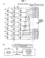
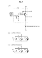
- a conceptual view of the battery pack of the first embodiment is shown in Fig. 1(A)
- a configuration view of the battery pack of the first embodiment is shown in Fig. 1(B) .
- the battery pack of the first embodiment includes a battery assembly 10 in which a plurality of secondary battery cell parallel modules 11 (in the example shown in the drawings, seven secondary battery cell parallel modules 11 1 , 11 2 , 11 3 , 11 4 , 11 5 , 11 6 , and 11 7 ) made up of a plurality of secondary battery cells 12 (in the example shown in the drawings, 21 secondary battery cells 12 11 , 12 12 , 12 13 , 12 21 , 12 22 , 12 23 , 12 31 , 12 32 , 12 33 , 12 41 , 12 42 , 12 43 , 12 51 , 12 52 , 12 53 , 12 61 , 12 62 , 12 63 , 12 71 , 12 72 , and 12 73 ) connected in parallel are connected in series, and an auxiliary charging/discharging device 13.
- a plurality of secondary battery cell parallel modules 11 in the example shown in the drawings, seven secondary battery cell parallel modules 11 1 , 11 2 , 11 3 , 11 4 , 11 5 , 11 6
- the auxiliary charging/discharging device 13 is basically connected in parallel to any of the secondary battery cell parallel modules 11. Furthermore, the battery pack of the first embodiment has a voltage measurement device 14 that measures voltages across the secondary battery cell parallel modules 11.
- the secondary battery cell 12 is made up of, but not limited to, a lithium-ion secondary battery.
- the battery pack of the first embodiment includes a battery assembly 10 in which a plurality of secondary battery cell parallel modules 11, each of which is made up of a plurality of secondary battery cells 12 connected in parallel, are connected in series, a charging/discharging control circuit 15 connected to the battery assembly 10 via a connecting part (particularly, a connector 16 having a tap portion), and a voltage measurement device 14 and an auxiliary charging/discharging device 13 tapped from the connecting part (particularly, the connector 16 having the tap portion) and connected to the battery assembly 10, wherein the voltage measurement device 14 measures voltages across the secondary battery cell parallel modules 11.
- the charging/discharging control circuit 15 is made up of a well-known circuit having an MPU or storage means (e.g., made up of an EEPROM).
- the voltage measurement device 14, which measures the voltages across the secondary battery cell parallel modules 11, is also made up of a well-known circuit.
- a power supply of each of the charging/discharging control circuit 15 and the voltage measurement device 14 is the secondary battery cell 12 constituting the battery pack.
- the charging/discharging control circuit 15 is equipped with a well-known battery protection circuit (not shown). The battery protection circuit is operated to stop a function of the battery pack as needed.
- the number of auxiliary charging/discharging devices 13 is one, although not limited thereto.
- the auxiliary charging/discharging device 13 is made up of the secondary battery cell, specifications of which are the same as those of the secondary battery cell 12 constituting the battery assembly 10.
- second switching means SW-A and SW-B (in detail, seven sets of second switching means SW-A 1 , SW-B 1 , SW-A 2 , SW-B 2 , SW-A 3 , SW-B 3 , SW-A 4 , SW-B 4 , SW-A 5 , SW-B 5 , SW-A 6 , SW-B 6 , SW-A 7 , and SW-B 7 ) are disposed between the auxiliary charging/discharging device 13 and the secondary battery cell parallel module 11.
- the auxiliary charging/discharging device 13 and the second switching means SW-A and SW-B, and the secondary battery cell parallel modules 11 and the second switching means SW-A and SW-B are connected by wiring.
- the conduction/nonconduction of the second switching means SW-A and SW-B is controlled by the voltage measurement device 14, although not limited thereto.
- one ends of the secondary battery cells 12 are provided with switching means SW (switching means SW 11, SW 12 , SW 13 , SW 21 , SW 22 , SW 23 , SW 31 , SW 32 , SW 33 , SW 41 , SW 42 , SW 43 , SW 51 , SW 52 , SW 53 , SW 61 , SW 62 , SW 63 , SW 71 , SW 72 , and SW 73 ).
- switching means SW switching means SW 11, SW 12 , SW 13 , SW 21 , SW 22 , SW 23 , SW 31 , SW 32 , SW 33 , SW 41 , SW 42 , SW 43 , SW 51 , SW 52 , SW 53 , SW 61 , SW 62 , SW 63 , SW 71 , SW 72 , and SW 73 .
- the switching means SW is set to a nonconduction state, and thereby the connection to the secondary battery cell 12 at which the abnormality has arisen in the secondary battery cell parallel module 11 is physically released.
- the control of the switching means SW is carried out by the voltage measurement device 14, although not limited thereto.
- the switching means SW and the voltage measurement device 14 are connected by wiring (not shown). However, not being limited to this, the switching means SW and the voltage measurement device 14 may be connected without a wire.
- the switching means SW is made up of a p-channel MOSFET.
- the abnormal secondary battery cell for example, an internal short-circuit occurs.
- a direction of current flowing along an interior is opposite to that of current flowing along an interior of the normal secondary battery cell.
- a value of the flowing current is higher than that of the normal secondary battery cell.
- a potential across the switching means SW i.e. by measuring a value of ON resistance of the MOSFET, it can be checked whether an abnormality has arisen in the secondary battery cell.
- the ON resistance of the MOSFET varies to some extent due to current and temperature, but may be sufficiently used if a direction of the current or a great difference in an amount of the current is merely measured. That is, under the control of the voltage measurement device 14, an ON/OFF control signal is sent to the switching means SW, and the switching means SW is placed in an ON state (conduction state).
- a potential between opposite ends of the MOSFET (terminal "A" and terminal “B") is measured, or a flowing direction of current at the opposite ends of the MOSFET is measured. Thereby, it can be checked whether an abnormality has arisen in the secondary battery cell 12.
- Figs. 7(B) and 7(C) the current flowing along the normal secondary battery cell is depicted by an outlined arrow, and the current flowing along the abnormal secondary battery cell is depicted by a black arrow.
- the auxiliary charging/discharging device 13 is connected in parallel to any secondary battery cell parallel module 11.
- the connection to the secondary battery cell at which the abnormality has arisen is released in the secondary battery cell parallel module including the secondary battery cell at which the abnormality has arisen, and the auxiliary charging/discharging device 13 is connected in parallel to the secondary battery cell parallel module including the secondary battery cell at which the abnormality has arisen.
- the auxiliary charging/discharging device 13 is connected in parallel to the secondary battery cell parallel module having the highest voltage between its both ends. Further, during discharging, when there is no abnormality in the secondary battery cells, the auxiliary charging/discharging device 13 is connected in parallel to the secondary battery cell parallel module having the lowest voltage between its both ends.
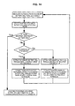
- Figs. 2 to 6 are conceptual views of the battery pack and Fig. 14 that is a flow chart.
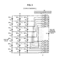
- the auxiliary charging/discharging device 13 is connected in parallel to any secondary battery cell parallel module 11.
- the auxiliary charging/discharging device 13 is connected in parallel to the secondary battery cell parallel module 11 having the highest voltage between its both ends.
- the voltages across the secondary battery cell parallel modules 11 are measured by the voltage measurement device 14 at all times, and a state of charge of the secondary battery cell parallel module 11 is monitored at all times.
- the voltage measurement device 14 evaluates a result of measuring the voltages across the secondary battery cell parallel modules 11 at desired intervals of time.
- the second switching means SW-A5 and SW-B 5 switch to a conduction state under the control of the voltage measurement device 14, and the other second switching means SW-A and SW-B are placed in a nonconduction state.
- the auxiliary charging/discharging device 13 is connected in parallel to the secondary battery cell parallel module 11 5 .
- the auxiliary charging/discharging device 13 is connected in parallel, and thereby a charging speed in the secondary battery cell parallel module 11 5 in which the voltage between its both ends is the highest value becomes slow.
- the uniformity of the nature and the voltage across the secondary battery cell parallel module can be achieved, and the equilibrium of cell balance can be achieved.
- the charge of the auxiliary charging/discharging device 13 made up of the secondary battery cell can be performed.
- the state of charge (SOC) of the auxiliary charging/discharging device 13 made up of the secondary battery cell can be maintained to the same extent as the secondary battery cell.
- the abnormal secondary battery cell can be replaced at any time, and can be exchanged and used smoothly.
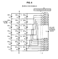
- the voltage measurement device 14 evaluates the result of measuring the voltages across the secondary battery cell parallel modules 11 at desired intervals of time. As shown in Fig. 4 , when the voltage across the secondary battery cell parallel module 11 2 reaches a highest value, the second switching means SW-A 2 and SW-B 2 switch to a conduction state under the control of the voltage measurement device 14, and the other second switching means SW-A and SW-B are placed in a nonconduction state. As a result, the auxiliary charging/discharging device 13 is connected in parallel to the secondary battery cell parallel module 11 2 . This operation is sequentially repeated to complete the charge of the battery pack.
- the auxiliary charging/discharging device 13 is connected in parallel to the secondary battery cell parallel module having the lowest voltage between its both ends.
- the second switching means SW-A 5 and SW-B 5 switch to the conduction state under the control of the voltage measurement device 14, and the other second switching means SW-A and SW-B are placed in the nonconduction state.
- the auxiliary charging/discharging device 13 is connected in parallel to the secondary battery cell parallel module 11 5 .
- the auxiliary charging/discharging device 13 is connected in parallel, and thereby a discharging speed in the secondary battery cell parallel module 11 5 in which the voltage between its both ends is the lowest value becomes slow.
- the auxiliary charging/discharging device 13 made up of the secondary battery cell contributes to the discharge. That is, the auxiliary charging/discharging device 13 operates as additional capacity in the secondary battery cell parallel module.
- the voltage measurement device 14 evaluates the result of measuring the voltages across the secondary battery cell parallel modules 11 at desired intervals of time. As shown in Fig. 6 , when the voltage across the secondary battery cell parallel module 11 2 reaches a lowest value, the second switching means SW-A 2 and SW-B 2 switch to a conduction state under the control of the voltage measurement device 14, and the other second switching means SW-A and SW-B are placed in a nonconduction state. As a result, the auxiliary charging/discharging device 13 is connected in parallel to the secondary battery cell parallel module 11 2 . This operation is sequentially repeated to complete the discharge of the battery pack.
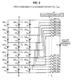
- the switching means SW when it is detected by the switching means SW that an abnormality has arisen at any secondary battery cell (in the example shown in Fig. 2 , when there is an abnormality in the secondary battery cell 12 52 ), the connection to the secondary battery cell 12 52 at which the abnormality has arisen is released in the secondary battery cell parallel module 11 5 including the secondary battery cell 12 52 at which the abnormality has arisen.
- the switching means SW 52 is set to a nonconduction state, and thereby the connection to the secondary battery cell 12 52 at which the abnormality has arisen in the secondary battery cell parallel module 11 5 is physically released.
- the auxiliary charging/discharging device 13 is connected in parallel to the secondary battery cell parallel module 11 5 including the secondary battery cell 12 52 at which the abnormality has arisen.
- the second switching means SW-A 5 and SW-B 5 switch to the conduction state, and the other second switching means SW-A and SW-B are placed in the nonconduction state.
- the auxiliary charging/discharging device 13 is connected in parallel to the secondary battery cell parallel module 11 5 .
- an operation of the secondary battery cell parallel module 11 5 exerts a charging/discharging function that is equivalent to that before the abnormality arose at the secondary battery cell.
- the charge/discharge in the conventional battery pack is performed.
- the method for charging/discharging the battery pack of the first embodiment may also be carried out in this state.
- the auxiliary charging/discharging device is connected in parallel to any secondary battery cell parallel module.
- the auxiliary charging/discharging device can also contribute to the charge/discharge, and the optimization of the cell balance in charging/discharging the entire battery pack in which the plurality of secondary battery cells are connected can be achieved. Charging/discharging of the entire battery pack can be made more efficient.
- the connection to the secondary battery cell at which the abnormality has arisen is released in the secondary battery cell parallel module including the secondary battery cell at which the abnormality has arisen, and the auxiliary charging/discharging device is connected in parallel to the secondary battery cell parallel module including the secondary battery cell at which the abnormality has arisen.
- the battery pack can be used without interruption, and the auxiliary charging/discharging device can function as a protection device having redundancy.
- a greater burden can be prevented from being imposed on the secondary battery cells constituting the secondary battery cell parallel module, and the secondary battery cell parallel module can be maintained in the same use state as before the abnormality arose at the secondary battery cell.
- a method of instantly setting the switching means to the nonconduction state in one of the secondary battery cells, setting the switching means to the conduction state in all the remaining secondary battery cells, and checking a state of variation in an open circuit voltage (OCV) of the secondary battery cell for which the switching means is set to the nonconduction state based on, for instance, the voltage measurement device 14 may be employed.
- OCV open circuit voltage
- a method of attaching an integrated circuit (IC) chip, which has temperature detecting means e.g., temperature detecting means that has a pn junction and measures temperature based on temperature dependency of an electric resistance value of the pn junction
- IC integrated circuit
- the IC chip may intervene for the control of the switching means SW caused by the voltage measurement device 14.
- the second embodiment relates to the battery pack according to the second aspect of the present technology and the method for charging/discharging the same.
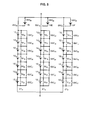
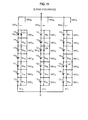
- a conceptual view of the battery pack of the second embodiment is shown in Fig. 8 .
- the battery pack of the second embodiment includes secondary battery cell serial modules, each of which is made up of a plurality of secondary battery cells connected in series, and an auxiliary charging/discharging device 13.
- one secondary battery cell serial module 21 D is made up of seven secondary battery cells 12 (12 D1 , 12 D2 , 12 D3 , 12 D4 , 12 D5 , 12 D6 , and 12 D7 ) connected in series.
- one secondary battery cell serial module 21 E is made up of seven secondary battery cells 12 (12 E1 , 12 E2 , 12 E3 , 12 E4 , 12 E5 , 12 E6 , and 12 E7 ) connected in series.
- one secondary battery cell serial module 21 F is made up of seven secondary battery cells 12 (12 F1 , 12 F2 , 12 F3 , 12 F4 , 12 F5 , 12 F6 , and 12 F7 ) connected in series.
- the three secondary battery cell serial modules 21 D , 21 E , and 21 F are connected in parallel.
- the battery pack of the second embodiment includes a voltage measurement device (not shown in Fig. 8 ), which measures voltages across the secondary battery cells 12.
- the secondary battery cell 12 is made up of a lithium-ion secondary battery, although not limited thereto.
- the battery pack of the second embodiment includes a battery assembly 10 made up of secondary battery cell serial modules 21 which are each made up of a plurality of secondary battery cells 12 and which are connected in parallel, a charging/discharging control circuit 15 connected to the battery assembly 10 via a connecting part (particularly, a connector 16 having a tap portion), and a voltage measurement device 14 and an auxiliary charging/discharging device 13 tapped from the connecting part (particularly, the connector 16 having the tap portion) and connected to the battery assembly 10, wherein the voltage measurement device 14 measures voltages across the secondary battery cells 12.
- the charging/discharging control circuit 15 and the voltage measurement device 14 may have a configuration and structure similar to the charging/discharging control circuit 15 and the voltage measurement device 14, both of which were described in the first embodiment.
- auxiliary charging/discharging devices 13 is one, although not limited thereto.
- the auxiliary charging/discharging device 13 is made up of the secondary battery cell, specifications of which are the same as those of the secondary battery cell 12 constituting the battery assembly 10.
- terminal parts TM terminal parts TM D1 , TM D2 , TM D3 , TM D4 , TM D5 , TM D6 , TM D7 , TM E1 , TM E2 , TM E3 , TM E4 , TM E5 , TM E6 , TM E7 , TM F1 , TM F2 , TM F3 , TM F4 , TM F5 , TM F6 , and TM F7 ) are installed on opposite ends of the secondary battery cells 12.
- the auxiliary charging/discharging device 13 is connected in parallel to the secondary battery cells 12 via the terminal parts TM and the on/off control means (not shown). The control of the on/off control means is performed by the voltage measurement device 14, although not limited thereto.
- second on/off control means SW' (second on/off control means SW' D1 , SW' D2 , SW' D3 , SW' D4 , SW' D5 , SW' D6 , SW' D7 , SW' E1 , SW' E2 , SW' E3 , SW' E4 , SW' E5 , SW' E6 , SW' E7 , SW' F1 , SW' F2 , SW' F3 , SW' F4 , SW' F5 , SW' F6 , and SW' F7 ) are installed on the respective secondary battery cell 12. Due to an operation of the second on/off control means SW', the opposite ends of the secondary battery cell at which the abnormality has arisen are short-circuited.
- the control of the second on/off control means SW' is performed by the voltage measurement device 14, although not limited thereto.
- the second on/off control means SW' and the voltage measurement device 14 are connected by wiring. However, not being limited to this, the second on/off control means SW' and the voltage measurement device 14 may be connected without a wire.
- the auxiliary charging/discharging device 13 is connected in parallel to any secondary battery cell 12.
- the secondary battery cell at which the abnormality has arisen is disconnected from the secondary battery cell serial module 21, and the auxiliary charging/discharging device 13 is connected in series to the secondary battery cell serial module 21.
- the auxiliary charging/discharging device 13 is connected in series to the secondary battery cell serial module 21 by an operation of third on/off control means SW' DA , SW' DB , SW' EA , SW' EB , SW' FA , and SW' FB . Furthermore, during charging, when there is no abnormality in the secondary battery cells, the auxiliary charging/discharging device 13 is connected in parallel to the secondary battery cell having the highest voltage between its both ends. Further, during discharging, when there is no abnormality in the secondary battery cells, the auxiliary charging/discharging device 13 is connected in parallel to the secondary battery cell having the lowest voltage between its both ends. Similar to the first embodiment, the on/off control means, the second on/off control means, and the third on/off control means may be made up of, for example, a MOSFET.
- Figs. 9 to 11 are conceptual views of the battery pack.
- the auxiliary charging/discharging device 13 is connected in parallel to any secondary battery cell 12.
- the auxiliary charging/discharging device 13 is connected in parallel to the secondary battery cell 12 having the highest voltage between its both ends.
- the voltages across the secondary battery cells 12 are measured by the voltage measurement device 14 at all times, and a state of charge of the secondary battery cell 12 is monitored at all times.
- the voltage measurement device 14 evaluates a result of measuring the voltages across the secondary battery cells 12 at desired intervals of time.
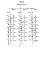
- the auxiliary charging/discharging devices 13D, 13E, and 13F are connected in parallel to the secondary battery cell 12 D2 , 12 E4 , 12 F6 via the on/off control means (not shown) and the terminal parts TM D2 , TM E4 , and TM F 6 under the control of the voltage measurement device 14.
- the auxiliary charging/discharging devices 13D, 13E, and 13F are connected in parallel, and thereby a charging speed of the secondary battery cell 12 in which the voltage between its both ends is the highest value becomes slow.
- the auxiliary charging/discharging devices 13D, 13E, and 13F each of which is made up of the secondary battery cell, can be charged.
- states of charge (SOCs) of the auxiliary charging/discharging devices 13D, 13E, and 13F made up of the secondary battery cell can be held to the same extent as the secondary battery cell.
- the abnormal secondary battery cell can be replaced at any time, and can be exchanged and used smoothly.
- the secondary battery cell in which the voltage between its both ends is the highest value is also changed in the secondary battery cell serial module.
- the voltage measurement device 14 evaluates the result of measuring the voltages across the secondary battery cells 12 at desired intervals of time, and the auxiliary charging/discharging devices 13 are connected in parallel to the secondary battery cell in which the voltage between its both ends is the highest value. This operation is sequentially repeated to complete the charge of the battery pack.
- the auxiliary charging/discharging devices 13 are connected in parallel to the secondary battery cell having the lowest voltage between its both ends.
- the auxiliary charging/discharging devices 13D, 13E, and 13F are connected in parallel to the secondary battery cells 12 D1 , 12 E3 , and 12 F5 via the on/off control means (not shown) and the terminal parts TM D1 , TM E3 , and TM F5 under the control of the voltage measurement device 14.
- the auxiliary charging/discharging devices 13D, 13E, and 13F are connected in parallel, and thereby a discharging speed in the secondary battery cells 12 D1 , 12 E3 , and 12 F5 in which the voltages between its both ends are the lowest values becomes slow.
- the auxiliary charging/discharging devices 13D, 13E, and 13F each of which is made up of the secondary battery cell, contribute to the discharge. That is, the auxiliary charging/discharging devices 13D, 13E, and 13F operate as additional capacities in the secondary battery cell serial module.
- the voltage measurement device 14 evaluates a result of measuring the voltages across the secondary battery cells 12 at desired intervals of time.
- the auxiliary charging/discharging devices 13 are connected in parallel to the secondary battery cells in which the voltages between its both ends are the lowest values. This operation is sequentially repeated to complete the discharge of the battery pack.
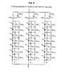
- the auxiliary charging/discharging device 13D is connected in series to the secondary battery cell serial module 21 D including the secondary battery cell 12 D2 at which the abnormality has arisen, more particularly one end of the secondary battery cell serial module 21 D , via the third on/off control means SW' DA and SW' DB .
- an operation of the secondary battery cell serial module 21 D exerts a charging/discharging function that is equivalent to that before the abnormality arose at the secondary battery cell.
- the illustration of connection states of the auxiliary charging/discharging devices 13E and 13F in the other secondary battery cell serial modules 21 E and 21 F is omitted.
- the charge/discharge in the conventional battery pack is performed.
- the method for charging/discharging the battery pack of the second embodiment may also be carried out in this state.
- the auxiliary charging/discharging devices can also contribute to the charge/discharge.
- the optimization of cell balance can be achieved.
- the efficiency of the charge/discharge of the entire battery pack can be achieved.
- the battery pack of the second embodiment or in the method for charging/discharging the same during charging/discharging, when there is an abnormality in any secondary battery cell, the secondary battery cell at which the abnormality has arisen is disconnected from the secondary battery cell serial module, and the auxiliary charging/discharging device is connected in series to the secondary battery cell serial module.
- the battery pack can be used without interruption, and the auxiliary charging/discharging device can function as a protection device having redundancy.
- a greater burden can be prevented from being imposed on the secondary battery cells constituting the secondary battery cell parallel module, and the secondary battery cell serial module can be maintained in the same use state as before the abnormality arose at the secondary battery cell.
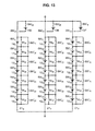
- one auxiliary charging/discharging device 13 may be disposed for a plurality of secondary battery cell serial modules.
- switching means SW are installed on one ends of the respective secondary battery cells. Based on operations of the switching means SW (switching means SW D1 , SW D2 , SW D3 , SW D4 , SW D5 , SW D6 , SW D7 , SW E1 , SW E2 , SW E3 , SW E4 , SW E5 , SW E6 , SW E7 , SW F1 , SW F2 , SW F3 , SW F4 , SW F5 , SW F6 , and SW F7 ), the secondary battery cell at which the abnormality has arisen may be configured to be disconnected from the secondary battery cell serial module.
- the connection to the secondary battery cell at which the abnormality has arisen in the secondary battery cell serial module is physically released.
- the voltage across each switching means SW is measured.
- the control of the switching means SW may be performed by the voltage measurement device 14, or by providing a switching means control device.
- the temperature of the secondary battery cell is measured, and thereby it may be detected whether or not the abnormality of the secondary battery cell occurs.
- the method of detecting the abnormal secondary battery cell in addition to the method of using the above-mentioned switching means, like the first embodiment, a method of instantly setting the switching means to the nonconduction state in one of the secondary battery cells, setting the switching means to the conduction state in all the remaining secondary battery cells, and checking a state of variation in an open circuit voltage of the secondary battery cell in which the switching means is set to the nonconduction state based on, for instance, the voltage measurement device 14 may be employed.
- the secondary battery cell at which the abnormality has arisen can be detected.
- an abnormality detection circuit e.g., an abnormality detection circuit made up of a resistor and an analog/digital converter (ADC) that detects the abnormality of the secondary battery cell may be installed on the auxiliary charging/discharging device 13.
- the abnormality detection circuit is connected in series to the auxiliary charging/discharging device 13.
- the present technology has been described based on the preferred embodiments, the present technology is not limited to these embodiments.
- the configurations, the structures, and the connection relationships of the battery pack, the battery assembly, the secondary battery cell, the auxiliary charging/discharging device, and the voltage measurement device described in the embodiments are illustrative, and may be appropriately modified.
- the battery pack may be applied to, for example, such power consumption devices as electric automobiles (including hybrid cars), golf carts, electric carts, electric motorcycles, electric power-assisted bicycles, railroad vehicles.
- the battery pack can be discharged, or be charged using energy generated from such a device.
- power consumption devices are each provided with, for instance, a control device including a battery level display, or a control device that conducts information processing associated with the control of the power consumption device on the basis of information about the secondary battery cell.
Abstract
Description
- The present disclosure relates to a battery pack, a method for charging/discharging the same, and a power consumption device.
- A battery pack has already been used for a variety of portable devices such as mobile phones, digital still cameras, handheld game consoles, laptop personal computers, and electric tools. Thus, at present, not being limited to this, the battery pack is being used in fields that require higher output and higher capacity such as electric power-assisted bicycles and electric automobiles, and furthermore, household electric storage devices.
- As a secondary battery cell incorporated in the battery pack, one of the most commonly used cells at present is a lithium-ion secondary battery cell. The lithium-ion secondary battery cell has a very wide range of uses due to a number of characteristics, such as that it can be repetitively used by charge, that it has high-voltage output, that it has high energy density, that it has low self-discharge, and that it has long service life. Further, to meet requirements of devices for higher output and higher capacity, cases of making the secondary battery cells (single cells) into multiple serial connections and multiple parallel connections and using them in the form of a battery assembly are also increasing. This usage has a great advantage but causes a processed quantity of energy to be greatly increased. As such, there is a need to more appropriately deal with the usage than has been done conventionally.
- Typically, the secondary battery cell is provided with a protection circuit so as to monitor the conditions of overcharge, overdischarge, overcurrent, and temperature, and not to be used in dangerous conditions or to cause characteristic degradation. Thus, conventionally, when the protection circuit operates, a charge/discharge operation of the battery pack as a whole is stopped, and thereby a protective function is realized.
- However, in the battery pack having a plurality of secondary battery cells, due to an abnormality of only one secondary battery cell or some of the secondary battery cells, performing a protective operation of the entire battery pack causes operations of all of various devices (called "power consumption devices"), which are supplied with power from the battery pack, to be stopped. For this reason, the disconnection of the secondary battery cell(s) at which the abnormality has arisen from the battery assembly is taken into consideration. However, when the secondary battery cells are connected in series, all of the secondary battery cells connected in series are out of use (see
Fig. 15(A) ). - An electric storage device for solving this problem is well known from Japanese Patent No.
3331529 - Patent Literature 1: Japanese Patent No.
3331529 - Incidentally, when the secondary battery cells are connected in parallel, for example when an abnormality has arisen at one secondary battery cell, the power supplied to the power consumption device is reduced in proportion to one secondary battery cell, and a burden of the normal secondary battery cell is increased (see
Fig. 15(B) ). There is a risk of exerting a bad influence on operating time and characteristics of the secondary battery cell. In the electric storage device disclosed in Japanese Patent No.3331529 - Accordingly, the present disclosure suggests a battery pack capable of achieving efficient charging/discharging of the entire battery pack in which a plurality of secondary battery cells are connected, a method for charging/discharging the same, and a power consumption device into which such a battery pack is incorporated.
- According to a first aspect of the present disclosure, there is provided a battery pack, which includes: a battery assembly in which a plurality of secondary battery cell parallel modules, each of which includes a plurality of secondary battery cells connected in parallel, are connected in series; and an auxiliary charging/discharging device, wherein the auxiliary charging/discharging device is connected in parallel to an arbitrary one of the secondary battery cell parallel modules.
- Further, according to a second aspect of the present disclosure, there is provided a battery pack, which includes: a secondary battery cell serial module including a plurality of secondary battery cells connected in series; and an auxiliary charging/discharging device,
wherein, when there is no abnormality in the secondary battery cells during charging/discharging, the auxiliary charging/discharging device is connected in parallel to any of the secondary battery cells, and
wherein, when there is an abnormality in any of the secondary battery cells during charging/discharging, the secondary battery cell at which the abnormality has arisen is disconnected from the secondary battery cell serial module, and the auxiliary charging/discharging device is connected in series to the secondary battery cell serial module. - Further, according to a third aspect of the present disclosure, there is provided a battery pack, which includes:
- a battery assembly in which a plurality of secondary battery cell parallel modules, each of which includes a plurality of secondary battery cells connected in parallel, are connected in series;
- a charging/discharging control circuit connected to the battery assembly via a connecting part; and
- a voltage measurement device and an auxiliary charging/discharging device tapped from the connecting part and connected to the battery assembly, wherein the voltage measurement device measures voltages across the secondary battery cell parallel modules.
- Also, according to the first aspect of the present disclosure, there is provided a method for charging/discharging a battery pack,
in which the battery pack includes an auxiliary charging/discharging device and a battery assembly in which a plurality of secondary battery cell parallel modules, each of which includes a plurality of secondary battery cells connected in parallel, are connected in series, the method includes: - when there is no abnormality in the secondary battery cells during charging/discharging, connecting the auxiliary charging/discharging device in parallel to any of the secondary battery cell parallel modules; and
- when there is an abnormality in any of the secondary battery cells during charging/discharging, releasing connection to the secondary battery cell at which the abnormality has arisen in the secondary battery cell parallel module including the secondary battery cell at which the abnormality has arisen, and connecting the auxiliary charging/discharging device in parallel to the secondary battery cell parallel module including the secondary battery cell at which the abnormality has arisen.
- Further, according to the second aspect of the present disclosure, there is provided a method for charging/discharging a battery pack,
in which the battery pack includes an auxiliary charging/discharging device and a secondary battery cell serial module including a plurality of secondary battery cells connected in series, the method includes: - when there is no abnormality in the secondary battery cells during charging/discharging, connecting the auxiliary charging/discharging device in parallel to any of the secondary battery cells; and
- when there is an abnormality in any of the secondary battery cells during charging/discharging, short-circuiting both ends of the secondary battery cell at which the abnormality has arisen, and connecting the auxiliary charging/discharging device in series to the secondary battery cell serial module.
- In the battery pack according to the first aspect of the present technology, the auxiliary charging/discharging device is connected in parallel to an arbitrary one of the secondary battery cell parallel modules. Further, in the battery pack according to the second aspect of the present technology, during charging/discharging, when there is no abnormality in the secondary battery cells, the auxiliary charging/discharging device is connected in parallel to any of the secondary battery cells. Furthermore, in the battery pack according to the third aspect of the present technology, the voltage measurement device and the auxiliary charging/discharging device are provided. As such, during charging/discharging of the secondary battery cells, the auxiliary charging/discharging device can also contribute to the charge/discharge, and the optimization of cell balance in charging/discharging the entire battery pack in which the plurality of secondary battery cells are connected can be achieved. The efficiency of the entire battery pack can be achieved. Furthermore, in the battery pack according to the second aspect of the present technology, during charging/discharging, when there is an abnormality in any of the secondary battery cells, the secondary battery cell at which the abnormality has arisen is disconnected from the secondary battery cell serial module, and the auxiliary charging/discharging device is connected in series to the secondary battery cell serial module. As such, it is not necessary to stop the use of the battery pack. Furthermore, the auxiliary charging/discharging device functions as a protection device combining redundancy, and a greater burden is not imposed on the secondary battery cell constituting the secondary battery cell serial module.
- In the method for charging/discharging the battery pack according to the first aspect of the present technology, during charging/discharging, when there is no abnormality in the secondary battery cells, the auxiliary charging/discharging device is connected in parallel to any of the secondary battery cell parallel modules. Further, in the method for charging/discharging the battery pack according to the second aspect of the present technology, during charging/discharging, when there is no abnormality in the secondary battery cells, the auxiliary charging/discharging device is connected in parallel to any of the secondary battery cells. As such, during charging/discharging of the secondary battery cells, the auxiliary charging/discharging device can also contribute to the charge/discharge, and the optimization of cell balance in charging/discharging the entire battery pack in which the plurality of secondary battery cells are connected can be achieved. The efficiency of the entire battery pack can be achieved. Furthermore, in the method for charging/discharging the battery pack according to the first aspect of the present technology, during charging/discharging, when there is an abnormality in any of the secondary battery cells, the connection to the secondary battery cell at which the abnormality has arisen is released in the secondary battery cell parallel module including the secondary battery cell at which the abnormality has arisen, and the auxiliary charging/discharging device is connected in parallel to the secondary battery cell parallel module including the secondary battery cell at which the abnormality has arisen. In the method for charging/discharging the battery pack according to the second aspect of the present technology, during charging/discharging, when there is an abnormality in any of the secondary battery cells, the both ends of the secondary battery cell at which the abnormality has arisen are short-circuited, and the auxiliary charging/discharging device is connected in series to the secondary battery cell serial module. As such, it is not necessary to stop the use of the battery pack. Furthermore, the auxiliary charging/discharging device functions as a protection device combining redundancy, and a greater burden is not imposed on the secondary battery cell constituting the secondary battery cell module.
- As described above, in the present technology, no special charge or management mechanism is required for the auxiliary charging/discharging device. The auxiliary charging/discharging device can be used as a part of the battery pack. In addition to this, the equilibrium of cell balance can be efficiently achieved. Furthermore, since the secondary battery cell and the auxiliary charging/discharging device are synchronized in a use state, when the abnormality of the secondary battery cell occurs, the replacement of the auxiliary charging/discharging device can be smoothly performed. Due to easy control, the redundancy of the secondary battery cell can be remarkably increased.
- Furthermore, in the power consumption device of the present technology which will be described below, the battery pack according to the first to third aspects of the present technology is provided. As such, the power consumption device can produce effects similar to the above-mentioned effects which the battery pack according to the first to third aspects of the present technology has.
-
- [
Fig. 1] Figs. 1(A) and 1(B) are a conceptual view of a battery pack of a first embodiment, and a configuration view of the battery pack of the first embodiment, respectively. - [
Fig. 2] Fig. 2 is a conceptual view when there is an abnormality in a secondary battery cell in the battery pack of the first embodiment. - [
Fig. 3] Fig. 3 is a conceptual view of the battery pack of the first embodiment during charging. - [
Fig. 4] Fig. 4 is a conceptual view of the battery pack of the first embodiment during charging. - [
Fig. 5] Fig. 5 is a conceptual view of the battery pack of the first embodiment during discharging. - [
Fig. 6] Fig. 6 is a conceptual view of the battery pack of the first embodiment during discharging. - [
Fig. 7] Figs. 7(A), 7(B) and 7(C) are an equivalent circuit diagram of switching means, a conceptual view for describing a flow of current during charging, and a conceptual view for describing a flow of current during discharging, respectively. - [
Fig. 8] Fig. 8 is a conceptual view of a battery pack of a second embodiment - [
Fig. 9] Fig. 9 is a conceptual view when there is an abnormality in a secondary battery cell in the battery pack of the second embodiment. - [
Fig. 10] Fig. 10 is a conceptual view of the battery pack of the second embodiment during charging. - [
Fig. 11] Fig. 11 is a conceptual view of the battery pack of the second embodiment during discharging. - [
Fig. 12] Fig. 12 is a conceptual view of a modification of the battery pack of the second embodiment. - [
Fig. 13] Fig. 13 is a conceptual view of another modification of the battery pack of the second embodiment. - [
Fig. 14] Fig. 14 is a flow chart of a method for charging/discharging the battery pack of the first embodiment. - [
Fig. 15] Figs. 15(A) and 15(B) are conceptual views for describing a problem when there is an abnormality in a secondary battery cell in a conventional battery pack. - Hereinafter, a description will be made of the present technology based on embodiments with reference to the drawings. However, the present technology is not limited to the embodiments, and various values and materials used in the embodiment are illustrative. Note that the description will be given in the following order.
- 1. Overall description of a battery pack according to first to third aspects of the present technology, and a method for charging/discharging the battery pack according to the first and second aspects of the present technology.
- 2. First embodiment (the battery pack according to the first and third aspects of the present technology, and the method for charging/discharging the battery pack according to the first aspect of the present technology).
- 3. Second embodiment (the battery pack according to the second aspect of the present technology, and the method for charging/discharging the battery pack according to the second aspect of the present technology), and so forth.
- The battery pack according to the first aspect of the present technology may be used in a form in which:
- during charging/discharging, when there is no abnormality in secondary battery cells, an auxiliary charging/discharging device is connected in parallel to any one of secondary battery cell parallel modules; and
- during charging/discharging, when there is an abnormality in any one of the secondary battery cells, the connection to the secondary battery cell at which the abnormality has arisen is released in the secondary battery cell parallel module having the secondary battery cell at which the abnormality has arisen, and the auxiliary charging/discharging device is connected in parallel to the secondary battery cell parallel module having the secondary battery cell at which the abnormality has arisen.
- Thus, in the preferred form of the battery pack according to the first aspect of the present technology, during charging, when there is no abnormality in the secondary battery cells, the auxiliary charging/discharging device may be configured to be connected in parallel to the secondary battery cell parallel module having the highest voltage between its both ends. Further, in the preferred form of the battery pack according to the first aspect of the present technology which includes this preferred configuration, during discharging, when there is no abnormality in the secondary battery cells, the auxiliary charging/discharging device may be configured to be connected in parallel to the secondary battery cell parallel module having the lowest voltage between its both ends.
- In the method for charging/discharging the battery pack according to the first aspect of the present technology, during charging, when there is no abnormality in the secondary battery cells, the auxiliary charging/discharging device may be configured to be connected in parallel to the secondary battery cell parallel module having the highest voltage between its both ends. Thus, in the method for charging/discharging the battery pack according to the first aspect of the present technology which includes this preferred configuration, during discharging, when there is no abnormality in the secondary battery cells, the auxiliary charging/discharging device may be configured to be connected in parallel to the secondary battery cell parallel module having the lowest voltage between its both ends.
- In the battery pack according to the second aspect of the present technology, during charging, when there is no abnormality in the secondary battery cells, the auxiliary charging/discharging device may be configured to be connected in parallel to the secondary battery cell having the highest voltage between its both ends. Thus, in the battery pack according to the second aspect of the present technology which includes this preferred configuration, during discharging, when there is no abnormality in the secondary battery cells, the auxiliary charging/discharging device may be configured to be connected in parallel to the secondary battery cell having the lowest voltage between its both ends.
- In the method for charging/discharging the battery pack according to the second aspect of the present technology, during charging, when there is no abnormality in the secondary battery cells, the auxiliary charging/discharging device may be configured to be connected in parallel to the secondary battery cell having the highest voltage between its both ends. Thus, in the method for charging/discharging the battery pack according to the second aspect of the present technology which includes this preferred configuration, during discharging, when there is no abnormality in the secondary battery cells, the auxiliary charging/discharging device may be configured to be connected in parallel to the secondary battery cell having the lowest voltage between its both ends.
- In the preferred form of the battery pack according to the first aspect of the present technology which includes the various preferred configurations described above, or in the method for charging/discharging the battery pack according to the first aspect of the present technology which includes the various preferred configurations described above, one end of each secondary battery cell is provided with switching means, and due to an operation of the switching means, the connection to the secondary battery cell at which the abnormality has arisen may be released in the secondary battery cell parallel module having the secondary battery cell at which the abnormality has arisen (in detail, for example, the connection to the secondary battery cell at which the abnormality has arisen is physically released in the secondary battery cell parallel module). In this case, it may be further configured to detect whether or not there is an abnormality in the secondary battery cell by measuring a voltage across the switching means. The control of the switching means may be carried out by a voltage measurement device to be described below, or may provide a switching means control device. Alternatively, it may be configured detect whether or not there is an abnormality in the secondary battery cell by measuring a temperature of the secondary battery cell.
- Further, in the preferred form of the battery pack according to the first aspect of the present technology which includes the various preferred configurations described above, or in the method for charging/discharging the battery pack according to the first aspect of the present technology which includes the various preferred configurations described above, it may be configured to provide a voltage measurement device that measures the voltages across the secondary battery cell parallel modules.
- In the battery pack according to the second aspect of the present technology which includes the various preferred configurations described above, or in the method for charging/discharging the battery pack according to the second aspect of the present technology which includes the various preferred configurations described above, each secondary battery cell is provided with switching means. Due to an operation of the switching means, opposite ends of the secondary battery cell at which the abnormality has arisen may be configured to be short-circuited. Alternatively, the opposite ends of the secondary battery cell at which the abnormality has arisen may be configured to be short-circuited, and furthermore, the connection between the secondary battery cell at which the abnormality has arisen and a secondary battery cell serial module may be configured to be physically released. In these cases, further, it may be configured to detect whether or not there is an abnormality in the secondary battery cell by measuring the voltage across the switching means. The control of the switching means may be carried out by the voltage measurement device to be described below, or may provide the switching means control device. Alternatively, it may be configured to detect whether or not there is an abnormality in the secondary battery cell by measuring the temperature of the secondary battery cell.
- In the preferred form of the battery pack according to the second aspect of the present technology which includes the various preferred configurations described above, or in the method for charging/discharging the battery pack according to the second aspect of the present technology which includes the various preferred configurations described above, an abnormality detection circuit that detects the abnormality of the secondary battery cell may be configured to be installed on the auxiliary charging/discharging device.
- Further, in the battery pack according to the second aspect of the present technology which includes the various preferred configurations described above, or in the method for charging/discharging the battery pack according to the second aspect of the present technology which includes the various preferred configurations described above, it may be configured to provide the voltage measurement device that measures the voltages across the secondary battery cells.
- Here, an abnormal secondary battery cell refers to, for example, the secondary battery cell in which an internal short-circuit occurs and in which a value of current flowing therethrough is higher than that of a normal secondary battery cell during charging, and a direction of current flowing through the interior thereof is opposite to that of current flowing through the normal secondary battery cell during discharging.
- In the battery pack according to the first aspect of the present technology or in the method for charging/discharging the battery pack according to the first aspect of the present technology, the number of auxiliary charging/discharging devices may be one or two or more. Thus, to connect the auxiliary charging/discharging device in parallel to the secondary battery cell parallel module, second switching means may be disposed, for example, between the auxiliary charging/discharging device and the secondary battery cell parallel module, and the auxiliary charging/discharging device and the second switching means, and the secondary battery cell parallel module and the second switching means may be connected by wiring.
- In the battery pack according to the second aspect of the present technology or in the method for charging/discharging the battery pack according to the second aspect of the present technology, the number of secondary battery cell serial modules is not limited to one, and may be two or more. In the latter case, a plurality of secondary battery cell serial modules may be connected in parallel. The number of auxiliary charging/discharging devices may be one or two or more. Thus, to connect the auxiliary charging/discharging device in parallel to the secondary battery cell, on/off control means may be disposed, for example, between the auxiliary charging/discharging device and the secondary battery cell, and the auxiliary charging/discharging device and the on/off control means, and the secondary battery cell and the on/off control means may be connected by wiring. When the auxiliary charging/discharging device is connected in series to the secondary battery cell serial module, the auxiliary charging/discharging device may be connected in series to the secondary battery cell serial module via second on/off control means. At which position of the secondary battery cell serial module the auxiliary charging/discharging device is connected in series is essentially arbitrary. For example, a form in which the auxiliary charging/discharging device is connected in series to one end of the secondary battery cell serial module may be exemplified.
- The auxiliary charging/discharging device may be the secondary battery cell, specifications of which are the same as or different from those of the secondary battery cell constituting the battery pack. According to circumstances, the auxiliary charging/discharging device may be made up of a condenser (or a capacitor), and a resistor for adjusting internal resistance and the condenser may also be combined. When withstand voltage is not sufficient for the secondary battery cell, a plurality of condensers may be used by serial connection.
- A lithium-ion secondary battery may be given as an example of the secondary battery cell. However, not being limited to the lithium-ion secondary battery, a type of the secondary battery to be used may be appropriately selected depending on required characteristics. A configuration and structure of the secondary battery may be a well-known configuration and structure. A shape of the secondary battery may also be a well-known cylindrical or angled shape. The charging/discharging control circuit may be made up of a well-known circuit having a micro processing unit (MPU) or storage means (e.g., made up of an electrically erasable programmable read-only memory (EEPROM)). The voltage measurement device for measuring the voltages across the secondary battery cell parallel modules may also be made up of a well-known circuit. Power supplies of the charging/discharging control circuit and the voltage measurement device may be the secondary battery cell constituting the battery pack. Further, the charging/discharging control circuit may be equipped with a well-known battery protection circuit, and the battery protection circuit may be operated to stop the function of the battery pack as needed. As the switching means, the second switching means, the on/off control means, the second on/off control means, or the third on/off control means to be described below, for example, a metal oxide semiconductor field effect transistor (MOSFET), may be exemplified. As a connecting part that connects the battery assembly and the charging/discharging control circuit, for example, a connector having a tap portion may be exemplified. According to circumstances, the voltage measurement device may be included in the charging/discharging control circuit.
- In the present technology, the battery pack may be applied, for example, to various power consumption devices such as electric automobiles (including hybrid cars), golf carts, electric carts, electric motorcycles, electric power-assisted bicycles, railroad vehicles, electric tools such as electric drills, power supply units or home energy servers (household electric storage devices), personal computers, mobile phones, personal digital assistants (PDAs), digital still cameras or video cameras, camcorders, electronic books, electronic dictionaries, music players, radios, headphones, cordless telephone extension units, electric shavers, refrigerators, air conditioners, television receivers or graphic display devices, monitors, stereophonic devices, water heaters, microwave ovens, dishwashers, washing machines, driers, lighting instruments such as interior lamps, game consoles, navigation systems, memory cards, pacemakers, hearing aids, medical instruments, toys, robots, load conditioners, and traffic lights, and may be a driving power supply or an assisting power supply for these power consumption devices. That is, the power consumption device of the present technology has the battery pack according to the first to third aspect of the present technology which includes the various preferred forms and configurations described above. Alternatively, the battery pack in the present technology may be applied, for instance, to instruments such as power storage power supplies for buildings including houses or power-generating facilities, may be used to supply power to these instruments, and may be used as an electric storage device in a so-called smart grid. This electric storage device may not only supply power but may also store electricity by supply of power from another power source. Furthermore, the battery pack in the present technology may be incorporated into home energy management systems (HEMSs) and building energy management systems (BEMSs). Further, as the power supply for charging the secondary battery cell constituting the battery pack, in addition to commercial power supplies, various solar batteries, fuel batteries, thermal power generating facilities, nuclear power generating facilities, water power generating facilities, wind power generating facilities, micro water power generating facilities, and geothermal power generating facilities may be exemplified. Regenerated energy which the power consumption device produces may also be exemplified. However, the power supply is not limited to these.
- The first embodiment relates to the battery pack according to the first to third aspects of the present technology and the method for charging/discharging the same. A conceptual view of the battery pack of the first embodiment is shown in
Fig. 1(A) , and a configuration view of the battery pack of the first embodiment is shown inFig. 1(B) . - The battery pack of the first embodiment includes a
battery assembly 10 in which a plurality of secondary battery cell parallel modules 11 (in the example shown in the drawings, seven secondary battery cellparallel modules secondary battery cells device 13. Thus, the auxiliary charging/dischargingdevice 13 is basically connected in parallel to any of the secondary battery cellparallel modules 11. Furthermore, the battery pack of the first embodiment has avoltage measurement device 14 that measures voltages across the secondary battery cellparallel modules 11. Thesecondary battery cell 12 is made up of, but not limited to, a lithium-ion secondary battery. - Further, as shown in
Fig. 1(B) , the battery pack of the first embodiment includes
abattery assembly 10 in which a plurality of secondary battery cellparallel modules 11, each of which is made up of a plurality ofsecondary battery cells 12 connected in parallel, are connected in series,
a charging/dischargingcontrol circuit 15 connected to thebattery assembly 10 via a connecting part (particularly, aconnector 16 having a tap portion), and
avoltage measurement device 14 and an auxiliary charging/dischargingdevice 13 tapped from the connecting part (particularly, theconnector 16 having the tap portion) and connected to thebattery assembly 10, wherein thevoltage measurement device 14 measures voltages across the secondary battery cellparallel modules 11. - Here, the charging/discharging
control circuit 15 is made up of a well-known circuit having an MPU or storage means (e.g., made up of an EEPROM). Thevoltage measurement device 14, which measures the voltages across the secondary battery cellparallel modules 11, is also made up of a well-known circuit. A power supply of each of the charging/dischargingcontrol circuit 15 and thevoltage measurement device 14 is thesecondary battery cell 12 constituting the battery pack. Further, the charging/dischargingcontrol circuit 15 is equipped with a well-known battery protection circuit (not shown). The battery protection circuit is operated to stop a function of the battery pack as needed. - In the battery pack of the first embodiment, the number of auxiliary charging/discharging
devices 13 is one, although not limited thereto. The auxiliary charging/dischargingdevice 13 is made up of the secondary battery cell, specifications of which are the same as those of thesecondary battery cell 12 constituting thebattery assembly 10. To connect the auxiliary charging/dischargingdevice 13 in parallel to the secondary battery cell parallel modules, second switching means SW-A and SW-B (in detail, seven sets of second switching means SW-A1, SW-B1, SW-A2, SW-B2, SW-A3, SW-B3, SW-A4, SW-B4, SW-A5, SW-B5, SW-A6, SW-B6, SW-A7, and SW-B7) are disposed between the auxiliary charging/dischargingdevice 13 and the secondary battery cellparallel module 11. Thus, the auxiliary charging/dischargingdevice 13 and the second switching means SW-A and SW-B, and the secondary battery cellparallel modules 11 and the second switching means SW-A and SW-B are connected by wiring. In the first embodiment, the conduction/nonconduction of the second switching means SW-A and SW-B is controlled by thevoltage measurement device 14, although not limited thereto. - In the battery pack of the first embodiment, one ends of the
secondary battery cells 12 are provided with switching means SW (switching means SW11, SW12, SW13, SW21, SW22, SW23, SW31, SW32, SW33, SW41, SW42, SW43, SW51, SW52, SW53, SW61, SW62, SW63, SW71, SW72, and SW73). Thus, due to an operation of the switching means, the connection to thesecondary battery cell 12 at which the abnormality has arisen is released in the secondary battery cellparallel module 11 including thesecondary battery cell 12 at which the abnormality has arisen. In detail, the switching means SW is set to a nonconduction state, and thereby the connection to thesecondary battery cell 12 at which the abnormality has arisen in the secondary battery cellparallel module 11 is physically released. The control of the switching means SW is carried out by thevoltage measurement device 14, although not limited thereto. The switching means SW and thevoltage measurement device 14 are connected by wiring (not shown). However, not being limited to this, the switching means SW and thevoltage measurement device 14 may be connected without a wire. - Here, by measuring a voltage across the switching means SW, it is detected whether or not the abnormality has arisen in the
secondary battery cell 12. For example, as shown inFig. 7(A) , the switching means SW is made up of a p-channel MOSFET. In the abnormal secondary battery cell, for example, an internal short-circuit occurs. For this reason, as shown inFig. 7(C) , during discharging, a direction of current flowing along an interior is opposite to that of current flowing along an interior of the normal secondary battery cell. As such, by measuring the direction of current flowing along the switching means SW, it can be checked whether an abnormality has arisen in the secondary battery cell. Further, in the abnormal secondary battery cell, as shown inFig. 7(B) , during charging, a value of the flowing current is higher than that of the normal secondary battery cell. As such, by measuring a potential across the switching means SW, i.e. by measuring a value of ON resistance of the MOSFET, it can be checked whether an abnormality has arisen in the secondary battery cell. The ON resistance of the MOSFET varies to some extent due to current and temperature, but may be sufficiently used if a direction of the current or a great difference in an amount of the current is merely measured. That is, under the control of thevoltage measurement device 14, an ON/OFF control signal is sent to the switching means SW, and the switching means SW is placed in an ON state (conduction state). A potential between opposite ends of the MOSFET (terminal "A" and terminal "B") is measured, or a flowing direction of current at the opposite ends of the MOSFET is measured. Thereby, it can be checked whether an abnormality has arisen in thesecondary battery cell 12. InFigs. 7(B) and 7(C) , the current flowing along the normal secondary battery cell is depicted by an outlined arrow, and the current flowing along the abnormal secondary battery cell is depicted by a black arrow. - Thus, in the battery pack of the first embodiment, during charging/discharging, when there is no abnormality in the
secondary battery cells 12, the auxiliary charging/dischargingdevice 13 is connected in parallel to any secondary battery cellparallel module 11. On the other hand, during charging/discharging, when there is an abnormality in any secondary battery cell, the connection to the secondary battery cell at which the abnormality has arisen is released in the secondary battery cell parallel module including the secondary battery cell at which the abnormality has arisen, and the auxiliary charging/dischargingdevice 13 is connected in parallel to the secondary battery cell parallel module including the secondary battery cell at which the abnormality has arisen. Furthermore, during charging, when there is no abnormality in the secondary battery cells, the auxiliary charging/dischargingdevice 13 is connected in parallel to the secondary battery cell parallel module having the highest voltage between its both ends. Further, during discharging, when there is no abnormality in the secondary battery cells, the auxiliary charging/dischargingdevice 13 is connected in parallel to the secondary battery cell parallel module having the lowest voltage between its both ends. - Hereinafter, the method for charging/discharging the battery pack of the first embodiment will be described with reference to
Figs. 2 to 6 that are conceptual views of the battery pack andFig. 14 that is a flow chart. - In the method for charging/discharging the secondary battery cells of the first embodiment, during charging/discharging, when there is no abnormality in the secondary battery cells, the auxiliary charging/discharging
device 13 is connected in parallel to any secondary battery cellparallel module 11. In detail, during charging, when there is no abnormality in the secondary battery cells, the auxiliary charging/dischargingdevice 13 is connected in parallel to the secondary battery cellparallel module 11 having the highest voltage between its both ends. During charging, the voltages across the secondary battery cellparallel modules 11 are measured by thevoltage measurement device 14 at all times, and a state of charge of the secondary battery cellparallel module 11 is monitored at all times. Thus, thevoltage measurement device 14 evaluates a result of measuring the voltages across the secondary battery cellparallel modules 11 at desired intervals of time. - For example, as shown in
Fig. 3 , when the voltage across the secondary battery cellparallel module 115 is a highest value, the second switching means SW-A5 and SW-B5 switch to a conduction state under the control of thevoltage measurement device 14, and the other second switching means SW-A and SW-B are placed in a nonconduction state. As a result, the auxiliary charging/dischargingdevice 13 is connected in parallel to the secondary battery cellparallel module 115. Thus, the auxiliary charging/dischargingdevice 13 is connected in parallel, and thereby a charging speed in the secondary battery cellparallel module 115 in which the voltage between its both ends is the highest value becomes slow. As a result, the uniformity of the nature and the voltage across the secondary battery cell parallel module can be achieved, and the equilibrium of cell balance can be achieved. The charge of the auxiliary charging/dischargingdevice 13 made up of the secondary battery cell can be performed. In addition, the state of charge (SOC) of the auxiliary charging/dischargingdevice 13 made up of the secondary battery cell can be maintained to the same extent as the secondary battery cell. The abnormal secondary battery cell can be replaced at any time, and can be exchanged and used smoothly. - As the charge of the battery pack progresses, the secondary battery cell parallel module in which the voltage between its both ends is the highest value is also changed. Accordingly, the
voltage measurement device 14 evaluates the result of measuring the voltages across the secondary battery cellparallel modules 11 at desired intervals of time. As shown inFig. 4 , when the voltage across the secondary battery cellparallel module 112 reaches a highest value, the second switching means SW-A2 and SW-B2 switch to a conduction state under the control of thevoltage measurement device 14, and the other second switching means SW-A and SW-B are placed in a nonconduction state. As a result, the auxiliary charging/dischargingdevice 13 is connected in parallel to the secondary battery cellparallel module 112. This operation is sequentially repeated to complete the charge of the battery pack. - On the other hand, during discharging, when there is no abnormality in the secondary battery cells, the auxiliary charging/discharging
device 13 is connected in parallel to the secondary battery cell parallel module having the lowest voltage between its both ends. For example, as shown inFig. 5 , when the voltage across the secondary battery cellparallel module 115 is the lowest value, the second switching means SW-A5 and SW-B5 switch to the conduction state under the control of thevoltage measurement device 14, and the other second switching means SW-A and SW-B are placed in the nonconduction state. As a result, the auxiliary charging/dischargingdevice 13 is connected in parallel to the secondary battery cellparallel module 115. Thus, the auxiliary charging/dischargingdevice 13 is connected in parallel, and thereby a discharging speed in the secondary battery cellparallel module 115 in which the voltage between its both ends is the lowest value becomes slow. As a result, the uniformity of the nature and the voltage across the secondary battery cell parallel module can be achieved, and the equilibrium of cell balance can be achieved. The auxiliary charging/dischargingdevice 13 made up of the secondary battery cell contributes to the discharge. That is, the auxiliary charging/dischargingdevice 13 operates as additional capacity in the secondary battery cell parallel module. - As the discharge of the battery pack progresses, the secondary battery cell parallel module in which the voltage between its both ends is the lowest value is also changed. Accordingly, the
voltage measurement device 14 evaluates the result of measuring the voltages across the secondary battery cellparallel modules 11 at desired intervals of time. As shown inFig. 6 , when the voltage across the secondary battery cellparallel module 112 reaches a lowest value, the second switching means SW-A2 and SW-B2 switch to a conduction state under the control of thevoltage measurement device 14, and the other second switching means SW-A and SW-B are placed in a nonconduction state. As a result, the auxiliary charging/dischargingdevice 13 is connected in parallel to the secondary battery cellparallel module 112. This operation is sequentially repeated to complete the discharge of the battery pack. - During charging/discharging, when it is detected by the switching means SW that an abnormality has arisen at any secondary battery cell (in the example shown in
Fig. 2 , when there is an abnormality in the secondary battery cell 1252), the connection to thesecondary battery cell 1252 at which the abnormality has arisen is released in the secondary battery cellparallel module 115 including thesecondary battery cell 1252 at which the abnormality has arisen. In detail, the switching means SW52 is set to a nonconduction state, and thereby the connection to thesecondary battery cell 1252 at which the abnormality has arisen in the secondary battery cellparallel module 115 is physically released. Thus, the auxiliary charging/dischargingdevice 13 is connected in parallel to the secondary battery cellparallel module 115 including thesecondary battery cell 1252 at which the abnormality has arisen. In detail, under the control of thevoltage measurement device 14, the second switching means SW-A5 and SW-B5 switch to the conduction state, and the other second switching means SW-A and SW-B are placed in the nonconduction state. As a result, the auxiliary charging/dischargingdevice 13 is connected in parallel to the secondary battery cellparallel module 115. Thus, an operation of the secondary battery cellparallel module 115 exerts a charging/discharging function that is equivalent to that before the abnormality arose at the secondary battery cell. - Then, in this state, without carrying out the method for charging/discharging the battery pack of the first embodiment, the charge/discharge in the conventional battery pack is performed. In this way, when there is an abnormal secondary battery cell, it is preferable to give a sign of warning that the exchange or maintenance of the secondary battery cell is required, and to call a user's attention. Further, when a plurality of auxiliary charging/discharging
devices 13 are provided, the method for charging/discharging the battery pack of the first embodiment may also be carried out in this state. - In this way, in the battery pack of the first embodiment or in the method for charging/discharging the same, during charging/discharging, when there is no abnormality in the secondary battery cells, the auxiliary charging/discharging device is connected in parallel to any secondary battery cell parallel module. As such, during charging/discharging the secondary battery cell, the auxiliary charging/discharging device can also contribute to the charge/discharge, and the optimization of the cell balance in charging/discharging the entire battery pack in which the plurality of secondary battery cells are connected can be achieved. Charging/discharging of the entire battery pack can be made more efficient. Furthermore, during charging/discharging, when there is an abnormality in any secondary battery cell, the connection to the secondary battery cell at which the abnormality has arisen is released in the secondary battery cell parallel module including the secondary battery cell at which the abnormality has arisen, and the auxiliary charging/discharging device is connected in parallel to the secondary battery cell parallel module including the secondary battery cell at which the abnormality has arisen. As such, the battery pack can be used without interruption, and the auxiliary charging/discharging device can function as a protection device having redundancy. A greater burden can be prevented from being imposed on the secondary battery cells constituting the secondary battery cell parallel module, and the secondary battery cell parallel module can be maintained in the same use state as before the abnormality arose at the secondary battery cell.
- As the method of detecting the abnormal secondary battery cell, in addition to the method of using the above-mentioned switching means, a method of instantly setting the switching means to the nonconduction state in one of the secondary battery cells, setting the switching means to the conduction state in all the remaining secondary battery cells, and checking a state of variation in an open circuit voltage (OCV) of the secondary battery cell for which the switching means is set to the nonconduction state based on, for instance, the
voltage measurement device 14 may be employed. When there is an abnormality in the secondary battery cell, the variation of the open circuit voltage (OCV) is greater than that of the normal secondary battery cell. Thus, by performing this operation on all the secondary battery cells, the secondary battery cell at which the abnormality has arisen can be detected. - Alternatively, for example, a method of attaching an integrated circuit (IC) chip, which has temperature detecting means (e.g., temperature detecting means that has a pn junction and measures temperature based on temperature dependency of an electric resistance value of the pn junction), to an outer surface of the secondary battery cell, and sending the temperature information measured by the IC chip to, for instance, the
voltage measurement device 14 with or without a wire may be employed. In the abnormal secondary battery cell at which the internal short-circuit occurs, the generation of heat is high. For this reason, based on a result of measuring the temperature of the secondary battery cell, it is possible to detect whether or not the abnormality of the secondary battery cell has arisen. When the switching means SW and thevoltage measurement device 14 are connected without a wire, the IC chip may intervene for the control of the switching means SW caused by thevoltage measurement device 14. - The second embodiment relates to the battery pack according to the second aspect of the present technology and the method for charging/discharging the same. A conceptual view of the battery pack of the second embodiment is shown in
Fig. 8 . - The battery pack of the second embodiment includes secondary battery cell serial modules, each of which is made up of a plurality of secondary battery cells connected in series, and an auxiliary charging/discharging
device 13. In detail, in the second embodiment, one secondary battery cellserial module 21D is made up of seven secondary battery cells 12 (12D1, 12D2, 12D3, 12D4, 12D5, 12D6, and 12D7) connected in series. Similarly, one secondary battery cellserial module 21E is made up of seven secondary battery cells 12 (12E1, 12E2, 12E3, 12E4, 12E5, 12E6, and 12E7) connected in series. Further, similarly, one secondary battery cellserial module 21F is made up of seven secondary battery cells 12 (12F1, 12F2, 12F3, 12F4, 12F5, 12F6, and 12F7) connected in series. Thus, the three secondary battery cellserial modules Fig. 8 ), which measures voltages across thesecondary battery cells 12. Thesecondary battery cell 12 is made up of a lithium-ion secondary battery, although not limited thereto. - Further, like that shown in
Fig. 1(B) , the battery pack of the second embodiment includes
abattery assembly 10 made up of secondary battery cellserial modules 21 which are each made up of a plurality ofsecondary battery cells 12 and which are connected in parallel,
a charging/dischargingcontrol circuit 15 connected to thebattery assembly 10 via a connecting part (particularly, aconnector 16 having a tap portion), and
avoltage measurement device 14 and an auxiliary charging/dischargingdevice 13 tapped from the connecting part (particularly, theconnector 16 having the tap portion) and connected to thebattery assembly 10, wherein thevoltage measurement device 14 measures voltages across thesecondary battery cells 12. Here, the charging/dischargingcontrol circuit 15 and thevoltage measurement device 14 may have a configuration and structure similar to the charging/dischargingcontrol circuit 15 and thevoltage measurement device 14, both of which were described in the first embodiment. - Even in the battery pack of the second embodiment, the number of auxiliary charging/discharging
devices 13 is one, although not limited thereto. The auxiliary charging/dischargingdevice 13 is made up of the secondary battery cell, specifications of which are the same as those of thesecondary battery cell 12 constituting thebattery assembly 10. To connect the auxiliary charging/dischargingdevice 13 in parallel to thesecondary battery cells 12, terminal parts TM (terminal parts TMD1, TMD2, TMD3, TMD4, TMD5, TMD6, TMD7, TME1, TME2, TME3, TME4, TME5, TME6, TME7, TMF1, TMF2, TMF3, TMF4, TMF5, TMF6, and TMF7) are installed on opposite ends of thesecondary battery cells 12. The auxiliary charging/dischargingdevice 13 is connected in parallel to thesecondary battery cells 12 via the terminal parts TM and the on/off control means (not shown). The control of the on/off control means is performed by thevoltage measurement device 14, although not limited thereto. - Further, second on/off control means SW' (second on/off control means SW'D1, SW'D2, SW'D3, SW'D4, SW'D5, SW'D6, SW'D7, SW'E1, SW'E2, SW'E3, SW'E4, SW'E5, SW'E6, SW'E7, SW'F1, SW'F2, SW'F3, SW'F4, SW'F5, SW'F6, and SW'F7) are installed on the respective
secondary battery cell 12. Due to an operation of the second on/off control means SW', the opposite ends of the secondary battery cell at which the abnormality has arisen are short-circuited. The control of the second on/off control means SW' is performed by thevoltage measurement device 14, although not limited thereto. The second on/off control means SW' and thevoltage measurement device 14 are connected by wiring. However, not being limited to this, the second on/off control means SW' and thevoltage measurement device 14 may be connected without a wire. - Thus, in the battery pack of the second embodiment, during charging/discharging, when there is no abnormality in the
secondary battery cells 12, the auxiliary charging/dischargingdevice 13 is connected in parallel to anysecondary battery cell 12. On the other hand, during charging/discharging, when there is an abnormality in any secondary battery cell, the secondary battery cell at which the abnormality has arisen is disconnected from the secondary battery cellserial module 21, and the auxiliary charging/dischargingdevice 13 is connected in series to the secondary battery cellserial module 21. Under the control of thevoltage measurement device 14, the auxiliary charging/dischargingdevice 13 is connected in series to the secondary battery cellserial module 21 by an operation of third on/off control means SW'DA, SW'DB, SW'EA, SW'EB, SW'FA, and SW'FB. Furthermore, during charging, when there is no abnormality in the secondary battery cells, the auxiliary charging/dischargingdevice 13 is connected in parallel to the secondary battery cell having the highest voltage between its both ends. Further, during discharging, when there is no abnormality in the secondary battery cells, the auxiliary charging/dischargingdevice 13 is connected in parallel to the secondary battery cell having the lowest voltage between its both ends. Similar to the first embodiment, the on/off control means, the second on/off control means, and the third on/off control means may be made up of, for example, a MOSFET. - Hereinafter, the method for charging/discharging the battery pack of the second embodiment will be described with reference to
Figs. 9 to 11 that are conceptual views of the battery pack. - In the method for charging/discharging the secondary battery cells of the second embodiment, during charging/discharging, when there is no abnormality in the secondary battery cells, the auxiliary charging/discharging
device 13 is connected in parallel to anysecondary battery cell 12. In detail, during charging, when there is no abnormality in the secondary battery cells, the auxiliary charging/dischargingdevice 13 is connected in parallel to thesecondary battery cell 12 having the highest voltage between its both ends. During charging, the voltages across thesecondary battery cells 12 are measured by thevoltage measurement device 14 at all times, and a state of charge of thesecondary battery cell 12 is monitored at all times. Thus, thevoltage measurement device 14 evaluates a result of measuring the voltages across thesecondary battery cells 12 at desired intervals of time. - For example, as shown in
Fig. 10 , when the voltage across thesecondary battery cell 12D2 in the secondary battery cellserial module 21D, the voltage across thesecondary battery cell 12E4 in the secondary battery cellserial module 21E, and the voltage across thesecondary battery cell 12F6 in the secondary battery cellserial module 21F are highest values, the auxiliary charging/dischargingdevices secondary battery cell voltage measurement device 14. Thus, the auxiliary charging/dischargingdevices secondary battery cell 12 in which the voltage between its both ends is the highest value becomes slow. As a result, the uniformity of the nature and the voltage across the secondary battery cell can be achieved, and the equilibrium of cell balance can be achieved. The auxiliary charging/dischargingdevices devices - As the charge of the battery pack progresses, the secondary battery cell in which the voltage between its both ends is the highest value is also changed in the secondary battery cell serial module. The
voltage measurement device 14 evaluates the result of measuring the voltages across thesecondary battery cells 12 at desired intervals of time, and the auxiliary charging/dischargingdevices 13 are connected in parallel to the secondary battery cell in which the voltage between its both ends is the highest value. This operation is sequentially repeated to complete the charge of the battery pack. - On the other hand, during discharging, when there is no abnormality in the secondary battery cells, the auxiliary charging/discharging
devices 13 are connected in parallel to the secondary battery cell having the lowest voltage between its both ends. For example, as shown inFig. 11 , when the voltage across thesecondary battery cell 12D1 in the secondary battery cellserial module 21D, the voltage across thesecondary battery cell 12E3 in the secondary battery cellserial module 21E, and the voltage across thesecondary battery cell 12F5 in the secondary battery cellserial module 21F are the lowest values, the auxiliary charging/dischargingdevices secondary battery cells voltage measurement device 14. Thus, the auxiliary charging/dischargingdevices secondary battery cells devices devices - As the discharge of the battery pack progresses, the secondary battery cells in which the voltages between its both ends are the lowest values are also changed. Accordingly, the
voltage measurement device 14 evaluates a result of measuring the voltages across thesecondary battery cells 12 at desired intervals of time. The auxiliary charging/dischargingdevices 13 are connected in parallel to the secondary battery cells in which the voltages between its both ends are the lowest values. This operation is sequentially repeated to complete the discharge of the battery pack. - During charging/discharging, when it is detected that there is an abnormality in any secondary battery cell (in the example shown in
Fig. 9 , when there is an abnormality in the secondary battery cell 12D2), opposite ends of thesecondary battery cell 12D2 at which the abnormality has arisen are short-circuited, and the auxiliary charging/dischargingdevice 13D is connected in series to the secondary battery cellserial module 21D. In detail, under the control of thevoltage measurement device 14, the second on/off control means SW'D2 is set to the conduction state, and the opposite ends of thesecondary battery cell 12D2 at which the abnormality has arisen are short-circuited. Thus, under the control of thevoltage measurement device 14, the auxiliary charging/dischargingdevice 13D is connected in series to the secondary battery cellserial module 21D including thesecondary battery cell 12D2 at which the abnormality has arisen, more particularly one end of the secondary battery cellserial module 21D, via the third on/off control means SW'DA and SW'DB. Thus, an operation of the secondary battery cellserial module 21D exerts a charging/discharging function that is equivalent to that before the abnormality arose at the secondary battery cell. Note that, inFig. 9 , the illustration of connection states of the auxiliary charging/dischargingdevices serial modules - Then, in this state, without carrying out the method for charging/discharging the battery pack of the second embodiment, the charge/discharge in the conventional battery pack is performed. In this way, when there is an abnormal secondary battery cell, it is preferable to give a sign of warning that the exchange or maintenance of the secondary battery cell is required, and to call a user's attention. Further, when a plurality of auxiliary charging/discharging
devices 13 are provided for one secondary battery cell serial module, the method for charging/discharging the battery pack of the second embodiment may also be carried out in this state. - In this way, in the battery pack of the second embodiment or in the method for charging/discharging the same, during charging/discharging the secondary battery cells, the auxiliary charging/discharging devices can also contribute to the charge/discharge. In the charge/discharge of the entire battery pack in which the plurality of secondary battery cells are connected, the optimization of cell balance can be achieved. The efficiency of the charge/discharge of the entire battery pack can be achieved. Further, in the battery pack of the second embodiment or in the method for charging/discharging the same, during charging/discharging, when there is an abnormality in any secondary battery cell, the secondary battery cell at which the abnormality has arisen is disconnected from the secondary battery cell serial module, and the auxiliary charging/discharging device is connected in series to the secondary battery cell serial module. As such, the battery pack can be used without interruption, and the auxiliary charging/discharging device can function as a protection device having redundancy. A greater burden can be prevented from being imposed on the secondary battery cells constituting the secondary battery cell parallel module, and the secondary battery cell serial module can be maintained in the same use state as before the abnormality arose at the secondary battery cell.
- As shown in
Fig. 12 , one auxiliary charging/dischargingdevice 13 may be disposed for a plurality of secondary battery cell serial modules. - Further, as shown in
Fig. 13 , like the first embodiment, switching means SW are installed on one ends of the respective secondary battery cells. Based on operations of the switching means SW (switching means SWD1, SWD2, SWD3, SWD4, SWD5, SWD6, SWD7, SWE1, SWE2, SWE3, SWE4, SWE5, SWE6, SWE7, SWF1, SWF2, SWF3, SWF4, SWF5, SWF6, and SWF7), the secondary battery cell at which the abnormality has arisen may be configured to be disconnected from the secondary battery cell serial module. In detail, for example, the connection to the secondary battery cell at which the abnormality has arisen in the secondary battery cell serial module is physically released. Thus, in this case, like the first embodiment, the voltage across each switching means SW is measured. Thereby, it is possible to detect whether or not the abnormality of the secondary battery cell occurs. The control of the switching means SW may be performed by thevoltage measurement device 14, or by providing a switching means control device. Alternatively, the temperature of the secondary battery cell is measured, and thereby it may be detected whether or not the abnormality of the secondary battery cell occurs. - Further, as the method of detecting the abnormal secondary battery cell, in addition to the method of using the above-mentioned switching means, like the first embodiment, a method of instantly setting the switching means to the nonconduction state in one of the secondary battery cells, setting the switching means to the conduction state in all the remaining secondary battery cells, and checking a state of variation in an open circuit voltage of the secondary battery cell in which the switching means is set to the nonconduction state based on, for instance, the
voltage measurement device 14 may be employed. Thus, by performing this operation on all the secondary battery cells, the secondary battery cell at which the abnormality has arisen can be detected. - Alternatively, an abnormality detection circuit (e.g., an abnormality detection circuit made up of a resistor and an analog/digital converter (ADC)) that detects the abnormality of the secondary battery cell may be installed on the auxiliary charging/discharging
device 13. The abnormality detection circuit is connected in series to the auxiliary charging/dischargingdevice 13. Thus, when there is an abnormality in current flowing through the abnormality detection circuit, it is possible to know that an abnormality has arisen at the secondary battery cell to which the auxiliary charging/dischargingdevice 13 is connected in parallel. - Although the present technology has been described based on the preferred embodiments, the present technology is not limited to these embodiments. The configurations, the structures, and the connection relationships of the battery pack, the battery assembly, the secondary battery cell, the auxiliary charging/discharging device, and the voltage measurement device described in the embodiments are illustrative, and may be appropriately modified. In the present technology, the battery pack may be applied to, for example, such power consumption devices as electric automobiles (including hybrid cars), golf carts, electric carts, electric motorcycles, electric power-assisted bicycles, railroad vehicles. Thus, to drive a conversion device (particularly, for example, a motor) which is provided in these and which converts power into a driving force by supplying the power, the battery pack can be discharged, or be charged using energy generated from such a device. These power consumption devices are each provided with, for instance, a control device including a battery level display, or a control device that conducts information processing associated with the control of the power consumption device on the basis of information about the secondary battery cell.
-
- 10
- Battery assembly
- 12, 1211 to 1273, 12D1 to 12F7
- Secondary battery cell
- 11, 111 to 117
- Secondary battery cell parallel module
- 13, 13D, 13E, 13F
- Auxiliary charging/discharging device
- 14
- Voltage measurement device
- 15
- Charging/discharging control circuit
- 16
- Connector
- 21, 21D to 21F
- Secondary battery cell serial module
- SW, SW11 to SW73, SWD1 to SWF7
- Switching means
- SW-A, SW-B, SW-A1 to SW-A7, SW-B1 to SW-B7
- Second switching means
- TM, TMD1 to TMF7
- Terminal part
- SW', SW'D1 to SW'F7
- Second on/off control means
- SW'DA to SW'FB
- Third on/off control means
Claims (20)
- A method for charging/discharging a battery pack having an auxiliary charging/discharging device and a battery assembly in which a plurality of secondary battery cell parallel modules, each of which includes a plurality of secondary battery cells connected in parallel, are connected in series, the method comprising:when there is no abnormality in the secondary battery cells during charging/discharging, connecting the auxiliary charging/discharging device in parallel to any of the secondary battery cell parallel modules; andwhen there is an abnormality in any of the secondary battery cells during charging/discharging, releasing connection to the secondary battery cell at which the abnormality has arisen in the secondary battery cell parallel module including the secondary battery cell at which the abnormality has arisen, and connecting the auxiliary charging/discharging device in parallel to the secondary battery cell parallel module including the secondary battery cell at which the abnormality has arisen.
- The method for charging/discharging a battery pack according to claim 1, wherein, when there is no abnormality in the secondary battery cells during charging, the auxiliary charging/discharging device is connected in parallel to a secondary battery cell parallel module having a highest voltage between both ends thereof.
- The method for charging/discharging a battery pack according to claim 1, wherein, when there is no abnormality in the secondary battery cells during discharging, the auxiliary charging/discharging device is connected in parallel to a secondary battery cell parallel module having a lowest voltage between both ends thereof.
- A method for charging/discharging a battery pack having an auxiliary charging/discharging device and a secondary battery cell serial module including a plurality of secondary battery cells connected in series, the method comprising:when there is no abnormality in the secondary battery cells during charging/discharging, connecting the auxiliary charging/discharging device in parallel to any of the secondary battery cells; andwhen there is an abnormality in any of the secondary battery cells during charging/discharging, short-circuiting both ends of the secondary battery cell at which the abnormality has arisen, and connecting the auxiliary charging/discharging device in series to the secondary battery cell serial module.
- The method for charging/discharging a battery pack according to claim 4, wherein, when there is no abnormality in the secondary battery cells during charging, the auxiliary charging/discharging device is connected in parallel to a secondary battery cell having a highest voltage between both ends thereof.
- The method for charging/discharging a battery pack according to claim 4, wherein, when there is no abnormality in the secondary battery cells during discharging, the auxiliary charging/discharging device is connected in parallel to a secondary battery cell having a lowest voltage between both ends thereof.
- A battery pack comprising:a battery assembly in which a plurality of secondary battery cell parallel modules, each of which includes a plurality of secondary battery cells connected in parallel, are connected in series; andan auxiliary charging/discharging device,wherein the auxiliary charging/discharging device is connected in parallel to any secondary battery cell parallel module.
- The battery pack according to claim 7, wherein
when there is no abnormality in the secondary battery cells during charging/discharging, the auxiliary charging/discharging device is connected in parallel to any of the secondary battery cell parallel modules, and
when there is an abnormality in any of the secondary battery cells during charging/discharging, connection to the secondary battery cell at which the abnormality has arisen is released in the secondary battery cell parallel module including the secondary battery cell at which the abnormality has arisen, and the auxiliary charging/discharging device is connected in parallel to the secondary battery cell parallel module including the secondary battery cell at which the abnormality has arisen. - The battery pack according to claim 8, wherein, when there is no abnormality in the secondary battery cells during charging, the auxiliary charging/discharging device is connected in parallel to a secondary battery cell parallel module having a highest voltage between both ends thereof.
- The battery pack according to claim 8, wherein, when there is no abnormality in the secondary battery cells during discharging, the auxiliary charging/discharging device is connected in parallel to a secondary battery cell parallel module having a lowest voltage between both ends thereof.
- The battery pack according to claim 8, wherein
switching means is installed on one end of each of the secondary battery cells; and
based on an operation of the switching means, the connection to the secondary battery cell at which the abnormality has arisen is released in the secondary battery cell parallel module including the secondary battery cell at which the abnormality has arisen. - The battery pack according to claim 11, wherein a voltage across the switching means is measured to detect whether or not the abnormality has arisen in the secondary battery cell.
- The battery pack according to claim 8, further comprising a voltage measurement device measuring voltages across each of the secondary battery cell parallel modules.
- A battery pack comprising:a secondary battery cell serial module including a plurality of secondary battery cells connected in series; andan auxiliary charging/discharging device,wherein, when there is no abnormality in the secondary battery cells during charging/discharging, the auxiliary charging/discharging device is connected in parallel to any of the secondary battery cells, andwherein, when there is an abnormality in any of the secondary battery cells during charging/discharging, the secondary battery cell at which the abnormality has arisen is disconnected from the secondary battery cell serial module, and the auxiliary charging/discharging device is connected in series to the secondary battery cell serial module.
- The battery pack according to claim 14, wherein, when there is no abnormality in the secondary battery cells during charging, the auxiliary charging/discharging device is connected in parallel to a secondary battery cell having a highest voltage between both ends thereof.
- The battery pack according to claim 14, wherein, when there is no abnormality in the secondary battery cells during discharging, the auxiliary charging/discharging device is connected in parallel to a secondary battery cell having a lowest voltage between both ends thereof.
- The battery pack according to claim 14, wherein
each of the secondary battery cells includes switching means; and
based on an operation of the switching means, both ends of the secondary battery cell at which the abnormality has arisen are short-circuited. - The battery pack according to claim 17, wherein a voltage across the switching means is measured to detect whether or not the abnormality has arisen in the secondary battery cell.
- A battery pack comprising:a battery assembly in which a plurality of secondary battery cell parallel modules, each of which includes a plurality of secondary battery cells connected in parallel, are connected in series;a charging/discharging control circuit connected to the battery assembly via a connecting part; anda voltage measurement device and an auxiliary charging/discharging device tapped from the connecting part and connected to the battery assembly, the voltage measurement device measuring voltages across each of the secondary battery cell parallel modules.
- A power consumption device comprising:a battery pack,wherein the battery pack includes
a battery assembly in which a plurality of secondary battery cell parallel modules, each of which includes a plurality of secondary battery cells connected in parallel, are connected in series, and
an auxiliary charging/discharging device,wherein the auxiliary charging/discharging device is connected in parallel to any secondary battery cell parallel module.
Applications Claiming Priority (2)
| Application Number | Priority Date | Filing Date | Title |
|---|---|---|---|
| JP2010235129A JP5625727B2 (en) | 2010-10-20 | 2010-10-20 | Battery pack, charging / discharging method thereof, and power consuming device |
| PCT/JP2011/070453 WO2012053292A1 (en) | 2010-10-20 | 2011-09-08 | Battery pack, method for charging/discharging same, and power consumption device |
Publications (3)
| Publication Number | Publication Date |
|---|---|
| EP2632016A1 true EP2632016A1 (en) | 2013-08-28 |
| EP2632016A4 EP2632016A4 (en) | 2014-07-23 |
| EP2632016B1 EP2632016B1 (en) | 2016-12-21 |
Family
ID=45975014
Family Applications (1)
| Application Number | Title | Priority Date | Filing Date |
|---|---|---|---|
| EP11834134.6A Active EP2632016B1 (en) | 2010-10-20 | 2011-09-08 | Battery pack, method for charging/discharging same, and power consumption device |
Country Status (5)
| Country | Link |
|---|---|
| US (1) | US10230249B2 (en) |
| EP (1) | EP2632016B1 (en) |
| JP (1) | JP5625727B2 (en) |
| CN (1) | CN103168406B (en) |
| WO (1) | WO2012053292A1 (en) |
Families Citing this family (32)
| Publication number | Priority date | Publication date | Assignee | Title |
|---|---|---|---|---|
| CN102723750A (en) * | 2012-05-02 | 2012-10-10 | 清华大学 | Hybrid packing type power battery pack |
| CN103427121A (en) * | 2012-05-23 | 2013-12-04 | 固纬电子实业股份有限公司 | Battery pack |
| JP6196756B2 (en) * | 2012-06-18 | 2017-09-13 | ローム株式会社 | Battery module and battery control circuit thereof, home storage battery and vehicle using the same |
| US20140008985A1 (en) * | 2012-07-06 | 2014-01-09 | Robert Bosh Gmbh | Method and system for control of energy storage devices |
| WO2014045745A1 (en) * | 2012-09-18 | 2014-03-27 | Necエナジーデバイス株式会社 | Power storage system and battery protection method |
| KR20140064487A (en) * | 2012-11-20 | 2014-05-28 | 삼성에스디아이 주식회사 | Rechargeable battery module |
| US10106038B2 (en) * | 2012-12-28 | 2018-10-23 | Johnson Controls Technology Company | Dual function battery system and method |
| JP5890341B2 (en) * | 2013-02-26 | 2016-03-22 | 東芝三菱電機産業システム株式会社 | Power storage device |
| JP6132240B2 (en) * | 2013-07-02 | 2017-05-24 | パナソニックIpマネジメント株式会社 | Storage battery system and control device |
| US9726731B2 (en) * | 2013-12-31 | 2017-08-08 | Chervon (Hk) Limited | Battery pack, method for detecting battery pack, charging assembly and electric tool |
| JPWO2016147323A1 (en) * | 2015-03-17 | 2017-11-30 | 株式会社東芝 | Battery system |
| DE102015106773A1 (en) * | 2015-04-30 | 2016-11-03 | Dr. Ing. H.C. F. Porsche Aktiengesellschaft | Battery system with battery control |
| JP2016220449A (en) * | 2015-05-22 | 2016-12-22 | 株式会社リコー | Secondary battery system, and control method and program therefor |
| US10622598B2 (en) | 2015-10-02 | 2020-04-14 | Simple Products Corporation | Variable battery system for flashlights |
| KR102511224B1 (en) * | 2015-11-05 | 2023-03-17 | 삼성전자주식회사 | Fuel Gauge System for Measuring Amount of Current of Battery and Portable Electronic Device Including the Same |
| JP6707843B2 (en) | 2015-11-17 | 2020-06-10 | オムロン株式会社 | Battery residual quantity display device, battery system and battery residual quantity display method |
| JP6392997B2 (en) * | 2015-11-18 | 2018-09-19 | NExT−e Solutions株式会社 | Control device, power storage device, and power storage system |
| JP6623725B2 (en) | 2015-12-01 | 2019-12-25 | オムロン株式会社 | Battery remaining amount estimation system and battery remaining amount estimation method |
| JP6883396B2 (en) * | 2016-08-25 | 2021-06-09 | 矢崎総業株式会社 | Quick charging device |
| CN106696748B (en) * | 2017-01-25 | 2019-06-28 | 华为技术有限公司 | A kind of charging pile system |
| JP7079129B2 (en) * | 2018-03-28 | 2022-06-01 | 日立Astemo株式会社 | Vehicle battery device |
| CN110380459B (en) * | 2018-04-13 | 2022-12-16 | 大有能源科技有限公司 | Charging method for stably charging battery of electric vehicle and prolonging power supply aging |
| US11211814B2 (en) * | 2018-04-23 | 2021-12-28 | Spiers New Technologies, Inc. | Circuitry to prevent lithium plating within a lithium ion battery |
| CN112119563A (en) | 2018-10-05 | 2020-12-22 | 艾达司股份有限公司 | Electricity storage system |
| CN112119562B (en) | 2018-10-19 | 2023-11-24 | 艾达司股份有限公司 | Power storage system |
| US11152813B2 (en) | 2018-11-08 | 2021-10-19 | GM Global Technology Operations LLC | Control systems and methods for battery with adjustable capacity |
| US11228059B2 (en) | 2018-11-08 | 2022-01-18 | GM Global Technology Operations LLC | Battery with multiple sets of output terminals and adjustable capacity |
| US10998595B2 (en) * | 2018-11-08 | 2021-05-04 | GM Global Technology Operations LLC | Modular vehicle battery |
| US11235748B2 (en) | 2019-03-01 | 2022-02-01 | GM Global Technology Operations LLC | Use of adjustable battery system within a vehicle with an HV battery or fuel cell system |
| US10723235B1 (en) * | 2019-08-30 | 2020-07-28 | Kitty Hawk Corporation | Flexible battery system for a vehicle |
| EP4106074A4 (en) * | 2020-02-12 | 2024-03-27 | Furukawa Electric Co Ltd | Degradation determination device for storage battery system, degradation determination method for storage battery system, storage battery system, and storage battery monitoring device |
| KR20220045440A (en) * | 2020-10-05 | 2022-04-12 | 주식회사 엘지에너지솔루션 | Battery module including buffer pad for preventing damage to battery cell, and battery pack including the same |
Citations (5)
| Publication number | Priority date | Publication date | Assignee | Title |
|---|---|---|---|---|
| US5235232A (en) * | 1989-03-03 | 1993-08-10 | E. F. Johnson Company | Adjustable-output electrical energy source using light-emitting polymer |
| EP0609101A1 (en) * | 1993-01-29 | 1994-08-03 | Canon Kabushiki Kaisha | Electric power accumulating apparatus and electric power system |
| JPH06225463A (en) * | 1993-01-20 | 1994-08-12 | Hitachi Ltd | Secondary cell apparatus |
| US20090079265A1 (en) * | 2001-01-24 | 2009-03-26 | Cochlear Limited | Power supply having an auxiliary power cell |
| US20100261043A1 (en) * | 2009-04-10 | 2010-10-14 | The Regents Of The University Of Michigan | Dynamically Reconfigurable Framework For A Large-Scale Battery System |
Family Cites Families (7)
| Publication number | Priority date | Publication date | Assignee | Title |
|---|---|---|---|---|
| JP3331529B2 (en) | 1993-01-29 | 2002-10-07 | キヤノン株式会社 | Power storage device and power system |
| JP3421519B2 (en) | 1996-02-13 | 2003-06-30 | 三洋電機株式会社 | Overcharge prevention circuit, overdischarge prevention circuit and charge / discharge control circuit |
| KR101081255B1 (en) * | 2007-02-09 | 2011-11-08 | 한국과학기술원 | Charge Equalization Apparatus |
| US7777451B2 (en) * | 2007-04-17 | 2010-08-17 | Chun-Chieh Chang | Rechargeable battery assembly and power system using same |
| CN100581024C (en) * | 2008-09-19 | 2010-01-13 | 哈尔滨工业大学 | Charging discharging fast equalizing apparatus for accumulator set or super capacitor set |
| JP5319224B2 (en) * | 2008-09-25 | 2013-10-16 | 株式会社東芝 | Assembled battery system |
| CN201490741U (en) * | 2009-09-03 | 2010-05-26 | 深圳市晖谱能源科技有限公司 | Battery balanced charging device |
-
2010
- 2010-10-20 JP JP2010235129A patent/JP5625727B2/en active Active
-
2011
- 2011-09-08 WO PCT/JP2011/070453 patent/WO2012053292A1/en active Application Filing
- 2011-09-08 EP EP11834134.6A patent/EP2632016B1/en active Active
- 2011-09-08 CN CN201180049592.0A patent/CN103168406B/en active Active
- 2011-09-08 US US13/879,580 patent/US10230249B2/en active Active
Patent Citations (5)
| Publication number | Priority date | Publication date | Assignee | Title |
|---|---|---|---|---|
| US5235232A (en) * | 1989-03-03 | 1993-08-10 | E. F. Johnson Company | Adjustable-output electrical energy source using light-emitting polymer |
| JPH06225463A (en) * | 1993-01-20 | 1994-08-12 | Hitachi Ltd | Secondary cell apparatus |
| EP0609101A1 (en) * | 1993-01-29 | 1994-08-03 | Canon Kabushiki Kaisha | Electric power accumulating apparatus and electric power system |
| US20090079265A1 (en) * | 2001-01-24 | 2009-03-26 | Cochlear Limited | Power supply having an auxiliary power cell |
| US20100261043A1 (en) * | 2009-04-10 | 2010-10-14 | The Regents Of The University Of Michigan | Dynamically Reconfigurable Framework For A Large-Scale Battery System |
Non-Patent Citations (1)
| Title |
|---|
| See also references of WO2012053292A1 * |
Also Published As
| Publication number | Publication date |
|---|---|
| JP5625727B2 (en) | 2014-11-19 |
| CN103168406B (en) | 2015-09-02 |
| CN103168406A (en) | 2013-06-19 |
| US20130200848A1 (en) | 2013-08-08 |
| JP2012090436A (en) | 2012-05-10 |
| WO2012053292A1 (en) | 2012-04-26 |
| EP2632016B1 (en) | 2016-12-21 |
| US10230249B2 (en) | 2019-03-12 |
| EP2632016A4 (en) | 2014-07-23 |
Similar Documents
| Publication | Publication Date | Title |
|---|---|---|
| US10230249B2 (en) | Battery pack, method for charging/discharging same, and power consumption device | |
| US11855250B2 (en) | Systems and methods for series battery charging | |
| US9276422B2 (en) | Battery pack and electric power consuming apparatus | |
| JP6225986B2 (en) | Power storage device and method for controlling power storage device | |
| EP3183791B1 (en) | Electric storage system | |
| KR101074785B1 (en) | A battery management system and control method thereof, and energy storage system including the battery management system | |
| EP2806525A2 (en) | Battery management system | |
| KR101344566B1 (en) | Electricity storage system | |
| CN103427452A (en) | Battery management system and energy storage system | |
| US8941354B2 (en) | Battery system | |
| KR20160025507A (en) | Electricity storage system, electricity storage module, and control method | |
| WO2013136413A1 (en) | Power storage system and method for controlling power storage module | |
| KR102623337B1 (en) | Pouch-type Cell Built-in Battery Management System | |
| KR20230063865A (en) | Battery system and method for controlling a battery system | |
| JP2020120481A (en) | Power storage system | |
| CN116885812A (en) | Battery unit, battery module, battery cluster and battery pack | |
| CN117543740A (en) | Power storage system |
Legal Events
| Date | Code | Title | Description |
|---|---|---|---|
| PUAI | Public reference made under article 153(3) epc to a published international application that has entered the european phase |
Free format text: ORIGINAL CODE: 0009012 |
|
| 17P | Request for examination filed |
Effective date: 20130306 |
|
| AK | Designated contracting states |
Kind code of ref document: A1 Designated state(s): AL AT BE BG CH CY CZ DE DK EE ES FI FR GB GR HR HU IE IS IT LI LT LU LV MC MK MT NL NO PL PT RO RS SE SI SK SM TR |
|
| DAX | Request for extension of the european patent (deleted) | ||
| A4 | Supplementary search report drawn up and despatched |
Effective date: 20140624 |
|
| RIC1 | Information provided on ipc code assigned before grant |
Ipc: H02J 7/02 20060101ALI20140617BHEP Ipc: H01M 2/10 20060101ALI20140617BHEP Ipc: H02J 7/00 20060101AFI20140617BHEP Ipc: H01M 10/44 20060101ALI20140617BHEP |
|
| 17Q | First examination report despatched |
Effective date: 20150127 |
|
| 17Q | First examination report despatched |
Effective date: 20150213 |
|
| GRAP | Despatch of communication of intention to grant a patent |
Free format text: ORIGINAL CODE: EPIDOSNIGR1 |
|
| INTG | Intention to grant announced |
Effective date: 20151222 |
|
| GRAP | Despatch of communication of intention to grant a patent |
Free format text: ORIGINAL CODE: EPIDOSNIGR1 |
|
| INTG | Intention to grant announced |
Effective date: 20160707 |
|
| GRAS | Grant fee paid |
Free format text: ORIGINAL CODE: EPIDOSNIGR3 |
|
| STAA | Information on the status of an ep patent application or granted ep patent |
Free format text: STATUS: GRANT OF PATENT IS INTENDED |
|
| GRAA | (expected) grant |
Free format text: ORIGINAL CODE: 0009210 |
|
| STAA | Information on the status of an ep patent application or granted ep patent |
Free format text: STATUS: THE PATENT HAS BEEN GRANTED |
|
| AK | Designated contracting states |
Kind code of ref document: B1 Designated state(s): AL AT BE BG CH CY CZ DE DK EE ES FI FR GB GR HR HU IE IS IT LI LT LU LV MC MK MT NL NO PL PT RO RS SE SI SK SM TR |
|
| REG | Reference to a national code |
Ref country code: GB Ref legal event code: FG4D |
|
| REG | Reference to a national code |
Ref country code: CH Ref legal event code: EP |
|
| REG | Reference to a national code |
Ref country code: IE Ref legal event code: FG4D |
|
| REG | Reference to a national code |
Ref country code: AT Ref legal event code: REF Ref document number: 856241 Country of ref document: AT Kind code of ref document: T Effective date: 20170115 |
|
| REG | Reference to a national code |
Ref country code: DE Ref legal event code: R096 Ref document number: 602011033711 Country of ref document: DE |
|
| PG25 | Lapsed in a contracting state [announced via postgrant information from national office to epo] |
Ref country code: LV Free format text: LAPSE BECAUSE OF FAILURE TO SUBMIT A TRANSLATION OF THE DESCRIPTION OR TO PAY THE FEE WITHIN THE PRESCRIBED TIME-LIMIT Effective date: 20161221 |
|
| REG | Reference to a national code |
Ref country code: LT Ref legal event code: MG4D |
|
| REG | Reference to a national code |
Ref country code: NL Ref legal event code: MP Effective date: 20161221 |
|
| PG25 | Lapsed in a contracting state [announced via postgrant information from national office to epo] |
Ref country code: LT Free format text: LAPSE BECAUSE OF FAILURE TO SUBMIT A TRANSLATION OF THE DESCRIPTION OR TO PAY THE FEE WITHIN THE PRESCRIBED TIME-LIMIT Effective date: 20161221 Ref country code: SE Free format text: LAPSE BECAUSE OF FAILURE TO SUBMIT A TRANSLATION OF THE DESCRIPTION OR TO PAY THE FEE WITHIN THE PRESCRIBED TIME-LIMIT Effective date: 20161221 Ref country code: GR Free format text: LAPSE BECAUSE OF FAILURE TO SUBMIT A TRANSLATION OF THE DESCRIPTION OR TO PAY THE FEE WITHIN THE PRESCRIBED TIME-LIMIT Effective date: 20170322 Ref country code: NO Free format text: LAPSE BECAUSE OF FAILURE TO SUBMIT A TRANSLATION OF THE DESCRIPTION OR TO PAY THE FEE WITHIN THE PRESCRIBED TIME-LIMIT Effective date: 20170321 |
|
| REG | Reference to a national code |
Ref country code: AT Ref legal event code: MK05 Ref document number: 856241 Country of ref document: AT Kind code of ref document: T Effective date: 20161221 |
|
| PG25 | Lapsed in a contracting state [announced via postgrant information from national office to epo] |
Ref country code: HR Free format text: LAPSE BECAUSE OF FAILURE TO SUBMIT A TRANSLATION OF THE DESCRIPTION OR TO PAY THE FEE WITHIN THE PRESCRIBED TIME-LIMIT Effective date: 20161221 Ref country code: RS Free format text: LAPSE BECAUSE OF FAILURE TO SUBMIT A TRANSLATION OF THE DESCRIPTION OR TO PAY THE FEE WITHIN THE PRESCRIBED TIME-LIMIT Effective date: 20161221 Ref country code: FI Free format text: LAPSE BECAUSE OF FAILURE TO SUBMIT A TRANSLATION OF THE DESCRIPTION OR TO PAY THE FEE WITHIN THE PRESCRIBED TIME-LIMIT Effective date: 20161221 |
|
| PG25 | Lapsed in a contracting state [announced via postgrant information from national office to epo] |
Ref country code: NL Free format text: LAPSE BECAUSE OF FAILURE TO SUBMIT A TRANSLATION OF THE DESCRIPTION OR TO PAY THE FEE WITHIN THE PRESCRIBED TIME-LIMIT Effective date: 20161221 |
|
| PG25 | Lapsed in a contracting state [announced via postgrant information from national office to epo] |
Ref country code: CZ Free format text: LAPSE BECAUSE OF FAILURE TO SUBMIT A TRANSLATION OF THE DESCRIPTION OR TO PAY THE FEE WITHIN THE PRESCRIBED TIME-LIMIT Effective date: 20161221 Ref country code: EE Free format text: LAPSE BECAUSE OF FAILURE TO SUBMIT A TRANSLATION OF THE DESCRIPTION OR TO PAY THE FEE WITHIN THE PRESCRIBED TIME-LIMIT Effective date: 20161221 Ref country code: IS Free format text: LAPSE BECAUSE OF FAILURE TO SUBMIT A TRANSLATION OF THE DESCRIPTION OR TO PAY THE FEE WITHIN THE PRESCRIBED TIME-LIMIT Effective date: 20170421 Ref country code: SK Free format text: LAPSE BECAUSE OF FAILURE TO SUBMIT A TRANSLATION OF THE DESCRIPTION OR TO PAY THE FEE WITHIN THE PRESCRIBED TIME-LIMIT Effective date: 20161221 Ref country code: RO Free format text: LAPSE BECAUSE OF FAILURE TO SUBMIT A TRANSLATION OF THE DESCRIPTION OR TO PAY THE FEE WITHIN THE PRESCRIBED TIME-LIMIT Effective date: 20161221 |
|
| PG25 | Lapsed in a contracting state [announced via postgrant information from national office to epo] |
Ref country code: SM Free format text: LAPSE BECAUSE OF FAILURE TO SUBMIT A TRANSLATION OF THE DESCRIPTION OR TO PAY THE FEE WITHIN THE PRESCRIBED TIME-LIMIT Effective date: 20161221 Ref country code: BG Free format text: LAPSE BECAUSE OF FAILURE TO SUBMIT A TRANSLATION OF THE DESCRIPTION OR TO PAY THE FEE WITHIN THE PRESCRIBED TIME-LIMIT Effective date: 20170321 Ref country code: PT Free format text: LAPSE BECAUSE OF FAILURE TO SUBMIT A TRANSLATION OF THE DESCRIPTION OR TO PAY THE FEE WITHIN THE PRESCRIBED TIME-LIMIT Effective date: 20170421 Ref country code: ES Free format text: LAPSE BECAUSE OF FAILURE TO SUBMIT A TRANSLATION OF THE DESCRIPTION OR TO PAY THE FEE WITHIN THE PRESCRIBED TIME-LIMIT Effective date: 20161221 Ref country code: BE Free format text: LAPSE BECAUSE OF FAILURE TO SUBMIT A TRANSLATION OF THE DESCRIPTION OR TO PAY THE FEE WITHIN THE PRESCRIBED TIME-LIMIT Effective date: 20161221 Ref country code: AT Free format text: LAPSE BECAUSE OF FAILURE TO SUBMIT A TRANSLATION OF THE DESCRIPTION OR TO PAY THE FEE WITHIN THE PRESCRIBED TIME-LIMIT Effective date: 20161221 Ref country code: PL Free format text: LAPSE BECAUSE OF FAILURE TO SUBMIT A TRANSLATION OF THE DESCRIPTION OR TO PAY THE FEE WITHIN THE PRESCRIBED TIME-LIMIT Effective date: 20161221 Ref country code: IT Free format text: LAPSE BECAUSE OF FAILURE TO SUBMIT A TRANSLATION OF THE DESCRIPTION OR TO PAY THE FEE WITHIN THE PRESCRIBED TIME-LIMIT Effective date: 20161221 |
|
| REG | Reference to a national code |
Ref country code: DE Ref legal event code: R097 Ref document number: 602011033711 Country of ref document: DE |
|
| REG | Reference to a national code |
Ref country code: FR Ref legal event code: PLFP Year of fee payment: 7 |
|
| PLBE | No opposition filed within time limit |
Free format text: ORIGINAL CODE: 0009261 |
|
| STAA | Information on the status of an ep patent application or granted ep patent |
Free format text: STATUS: NO OPPOSITION FILED WITHIN TIME LIMIT |
|
| 26N | No opposition filed |
Effective date: 20170922 |
|
| PG25 | Lapsed in a contracting state [announced via postgrant information from national office to epo] |
Ref country code: DK Free format text: LAPSE BECAUSE OF FAILURE TO SUBMIT A TRANSLATION OF THE DESCRIPTION OR TO PAY THE FEE WITHIN THE PRESCRIBED TIME-LIMIT Effective date: 20161221 |
|
| PG25 | Lapsed in a contracting state [announced via postgrant information from national office to epo] |
Ref country code: SI Free format text: LAPSE BECAUSE OF FAILURE TO SUBMIT A TRANSLATION OF THE DESCRIPTION OR TO PAY THE FEE WITHIN THE PRESCRIBED TIME-LIMIT Effective date: 20161221 |
|
| REG | Reference to a national code |
Ref country code: GB Ref legal event code: 732E Free format text: REGISTERED BETWEEN 20180315 AND 20180326 |
|
| REG | Reference to a national code |
Ref country code: CH Ref legal event code: PL |
|
| PG25 | Lapsed in a contracting state [announced via postgrant information from national office to epo] |
Ref country code: MC Free format text: LAPSE BECAUSE OF FAILURE TO SUBMIT A TRANSLATION OF THE DESCRIPTION OR TO PAY THE FEE WITHIN THE PRESCRIBED TIME-LIMIT Effective date: 20161221 |
|
| REG | Reference to a national code |
Ref country code: IE Ref legal event code: MM4A |
|
| PG25 | Lapsed in a contracting state [announced via postgrant information from national office to epo] |
Ref country code: LU Free format text: LAPSE BECAUSE OF NON-PAYMENT OF DUE FEES Effective date: 20170908 |
|
| PG25 | Lapsed in a contracting state [announced via postgrant information from national office to epo] |
Ref country code: LI Free format text: LAPSE BECAUSE OF NON-PAYMENT OF DUE FEES Effective date: 20170930 Ref country code: IE Free format text: LAPSE BECAUSE OF NON-PAYMENT OF DUE FEES Effective date: 20170908 Ref country code: CH Free format text: LAPSE BECAUSE OF NON-PAYMENT OF DUE FEES Effective date: 20170930 |
|
| REG | Reference to a national code |
Ref country code: DE Ref legal event code: R081 Ref document number: 602011033711 Country of ref document: DE Owner name: MURATA MANUFACTURING CO., LTD., NAGAOKAKYO-SHI, JP Free format text: FORMER OWNER: SONY CORPORATION, TOKYO, JP Ref country code: DE Ref legal event code: R081 Ref document number: 602011033711 Country of ref document: DE Owner name: MURATA MANUFACTURING CO., LTD., NAGAOKAKYO-SHI, JP Free format text: FORMER OWNER: TOHOKU MURATA MANUFACTURING CO., LTD, KORIYAMA-SHI, JP |
|
| REG | Reference to a national code |
Ref country code: FR Ref legal event code: PLFP Year of fee payment: 8 |
|
| PG25 | Lapsed in a contracting state [announced via postgrant information from national office to epo] |
Ref country code: MT Free format text: LAPSE BECAUSE OF NON-PAYMENT OF DUE FEES Effective date: 20170908 |
|
| REG | Reference to a national code |
Ref country code: FR Ref legal event code: TP Owner name: MURATA MANUFACTURING CO., LTD., JP Effective date: 20180829 |
|
| PG25 | Lapsed in a contracting state [announced via postgrant information from national office to epo] |
Ref country code: HU Free format text: LAPSE BECAUSE OF FAILURE TO SUBMIT A TRANSLATION OF THE DESCRIPTION OR TO PAY THE FEE WITHIN THE PRESCRIBED TIME-LIMIT; INVALID AB INITIO Effective date: 20110908 |
|
| PG25 | Lapsed in a contracting state [announced via postgrant information from national office to epo] |
Ref country code: CY Free format text: LAPSE BECAUSE OF NON-PAYMENT OF DUE FEES Effective date: 20161221 |
|
| PG25 | Lapsed in a contracting state [announced via postgrant information from national office to epo] |
Ref country code: MK Free format text: LAPSE BECAUSE OF FAILURE TO SUBMIT A TRANSLATION OF THE DESCRIPTION OR TO PAY THE FEE WITHIN THE PRESCRIBED TIME-LIMIT Effective date: 20161221 |
|
| PG25 | Lapsed in a contracting state [announced via postgrant information from national office to epo] |
Ref country code: TR Free format text: LAPSE BECAUSE OF FAILURE TO SUBMIT A TRANSLATION OF THE DESCRIPTION OR TO PAY THE FEE WITHIN THE PRESCRIBED TIME-LIMIT Effective date: 20161221 |
|
| PG25 | Lapsed in a contracting state [announced via postgrant information from national office to epo] |
Ref country code: AL Free format text: LAPSE BECAUSE OF FAILURE TO SUBMIT A TRANSLATION OF THE DESCRIPTION OR TO PAY THE FEE WITHIN THE PRESCRIBED TIME-LIMIT Effective date: 20161221 |
|
| PGFP | Annual fee paid to national office [announced via postgrant information from national office to epo] |
Ref country code: GB Payment date: 20230920 Year of fee payment: 13 |
|
| PGFP | Annual fee paid to national office [announced via postgrant information from national office to epo] |
Ref country code: FR Payment date: 20230928 Year of fee payment: 13 Ref country code: DE Payment date: 20230920 Year of fee payment: 13 |