EP2626012B1 - Deflecting guide catheter for mitral valve treatment - Google Patents
Deflecting guide catheter for mitral valve treatment Download PDFInfo
- Publication number
- EP2626012B1 EP2626012B1 EP13167307.1A EP13167307A EP2626012B1 EP 2626012 B1 EP2626012 B1 EP 2626012B1 EP 13167307 A EP13167307 A EP 13167307A EP 2626012 B1 EP2626012 B1 EP 2626012B1
- Authority
- EP
- European Patent Office
- Prior art keywords
- mitral valve
- distal
- plication
- guide catheter
- catheter
- Prior art date
- Legal status (The legal status is an assumption and is not a legal conclusion. Google has not performed a legal analysis and makes no representation as to the accuracy of the status listed.)
- Active
Links
- 210000004115 mitral valve Anatomy 0.000 title description 61
- 238000011282 treatment Methods 0.000 title description 11
- 238000000034 method Methods 0.000 claims description 59
- 239000000463 material Substances 0.000 claims description 37
- 230000033001 locomotion Effects 0.000 claims description 13
- 208000005907 mitral valve insufficiency Diseases 0.000 description 28
- 210000001519 tissue Anatomy 0.000 description 20
- 210000005240 left ventricle Anatomy 0.000 description 17
- 238000003384 imaging method Methods 0.000 description 16
- 238000010304 firing Methods 0.000 description 15
- 210000003813 thumb Anatomy 0.000 description 12
- 239000012636 effector Substances 0.000 description 11
- 238000002594 fluoroscopy Methods 0.000 description 9
- 238000002560 therapeutic procedure Methods 0.000 description 9
- 230000008859 change Effects 0.000 description 8
- 238000001356 surgical procedure Methods 0.000 description 8
- 238000013459 approach Methods 0.000 description 7
- 239000007943 implant Substances 0.000 description 7
- 210000001765 aortic valve Anatomy 0.000 description 6
- 229920002614 Polyether block amide Polymers 0.000 description 5
- 239000003146 anticoagulant agent Substances 0.000 description 5
- 229940127219 anticoagulant drug Drugs 0.000 description 5
- 230000009467 reduction Effects 0.000 description 5
- 229910001220 stainless steel Inorganic materials 0.000 description 5
- 239000010935 stainless steel Substances 0.000 description 5
- 230000000712 assembly Effects 0.000 description 4
- 238000000429 assembly Methods 0.000 description 4
- 230000001746 atrial effect Effects 0.000 description 4
- 230000000694 effects Effects 0.000 description 4
- 210000005246 left atrium Anatomy 0.000 description 4
- 230000007774 longterm Effects 0.000 description 4
- 229910052751 metal Inorganic materials 0.000 description 4
- 239000002184 metal Substances 0.000 description 4
- BASFCYQUMIYNBI-UHFFFAOYSA-N platinum Chemical compound [Pt] BASFCYQUMIYNBI-UHFFFAOYSA-N 0.000 description 4
- 238000002604 ultrasonography Methods 0.000 description 4
- 239000010963 304 stainless steel Substances 0.000 description 3
- 206010007559 Cardiac failure congestive Diseases 0.000 description 3
- 206010019280 Heart failures Diseases 0.000 description 3
- 206010067171 Regurgitation Diseases 0.000 description 3
- 229910000589 SAE 304 stainless steel Inorganic materials 0.000 description 3
- 238000002679 ablation Methods 0.000 description 3
- 239000008280 blood Substances 0.000 description 3
- 210000004369 blood Anatomy 0.000 description 3
- 238000004140 cleaning Methods 0.000 description 3
- 230000006870 function Effects 0.000 description 3
- 230000023597 hemostasis Effects 0.000 description 3
- 238000002513 implantation Methods 0.000 description 3
- 238000002347 injection Methods 0.000 description 3
- 239000007924 injection Substances 0.000 description 3
- 238000002324 minimally invasive surgery Methods 0.000 description 3
- 238000012634 optical imaging Methods 0.000 description 3
- 238000005457 optimization Methods 0.000 description 3
- 210000003540 papillary muscle Anatomy 0.000 description 3
- 229920000515 polycarbonate Polymers 0.000 description 3
- 239000004417 polycarbonate Substances 0.000 description 3
- 229920000642 polymer Polymers 0.000 description 3
- 238000010561 standard procedure Methods 0.000 description 3
- 230000002861 ventricular Effects 0.000 description 3
- 238000003466 welding Methods 0.000 description 3
- 229910000014 Bismuth subcarbonate Inorganic materials 0.000 description 2
- 229920000271 Kevlar® Polymers 0.000 description 2
- 229920000954 Polyglycolide Polymers 0.000 description 2
- 229920000508 Vectran Polymers 0.000 description 2
- 239000004979 Vectran Substances 0.000 description 2
- 239000000853 adhesive Substances 0.000 description 2
- 230000001070 adhesive effect Effects 0.000 description 2
- MGLUJXPJRXTKJM-UHFFFAOYSA-L bismuth subcarbonate Chemical compound O=[Bi]OC(=O)O[Bi]=O MGLUJXPJRXTKJM-UHFFFAOYSA-L 0.000 description 2
- 229940036358 bismuth subcarbonate Drugs 0.000 description 2
- 230000000740 bleeding effect Effects 0.000 description 2
- 230000017531 blood circulation Effects 0.000 description 2
- 230000008878 coupling Effects 0.000 description 2
- 238000010168 coupling process Methods 0.000 description 2
- 238000005859 coupling reaction Methods 0.000 description 2
- 230000002950 deficient Effects 0.000 description 2
- 230000003412 degenerative effect Effects 0.000 description 2
- 238000013461 design Methods 0.000 description 2
- 238000010586 diagram Methods 0.000 description 2
- 210000001105 femoral artery Anatomy 0.000 description 2
- 239000000835 fiber Substances 0.000 description 2
- 125000001153 fluoro group Chemical group F* 0.000 description 2
- 210000003709 heart valve Anatomy 0.000 description 2
- 238000012977 invasive surgical procedure Methods 0.000 description 2
- 239000004761 kevlar Substances 0.000 description 2
- 230000000670 limiting effect Effects 0.000 description 2
- 238000013507 mapping Methods 0.000 description 2
- 230000007246 mechanism Effects 0.000 description 2
- 229910001000 nickel titanium Inorganic materials 0.000 description 2
- HLXZNVUGXRDIFK-UHFFFAOYSA-N nickel titanium Chemical compound [Ti].[Ti].[Ti].[Ti].[Ti].[Ti].[Ti].[Ti].[Ti].[Ti].[Ti].[Ni].[Ni].[Ni].[Ni].[Ni].[Ni].[Ni].[Ni].[Ni].[Ni].[Ni].[Ni].[Ni].[Ni] HLXZNVUGXRDIFK-UHFFFAOYSA-N 0.000 description 2
- 230000007170 pathology Effects 0.000 description 2
- 229910052697 platinum Inorganic materials 0.000 description 2
- 239000004633 polyglycolic acid Substances 0.000 description 2
- 229950008885 polyglycolic acid Drugs 0.000 description 2
- 239000004810 polytetrafluoroethylene Substances 0.000 description 2
- 229920001343 polytetrafluoroethylene Polymers 0.000 description 2
- -1 prefereably Polymers 0.000 description 2
- 210000005245 right atrium Anatomy 0.000 description 2
- 238000012360 testing method Methods 0.000 description 2
- 229910001369 Brass Inorganic materials 0.000 description 1
- 208000006029 Cardiomegaly Diseases 0.000 description 1
- 229910000531 Co alloy Inorganic materials 0.000 description 1
- 229910000684 Cobalt-chrome Inorganic materials 0.000 description 1
- 208000032170 Congenital Abnormalities Diseases 0.000 description 1
- 229920001651 Cyanoacrylate Polymers 0.000 description 1
- 208000005189 Embolism Diseases 0.000 description 1
- HTTJABKRGRZYRN-UHFFFAOYSA-N Heparin Chemical compound OC1C(NC(=O)C)C(O)OC(COS(O)(=O)=O)C1OC1C(OS(O)(=O)=O)C(O)C(OC2C(C(OS(O)(=O)=O)C(OC3C(C(O)C(O)C(O3)C(O)=O)OS(O)(=O)=O)C(CO)O2)NS(O)(=O)=O)C(C(O)=O)O1 HTTJABKRGRZYRN-UHFFFAOYSA-N 0.000 description 1
- 206010048858 Ischaemic cardiomyopathy Diseases 0.000 description 1
- MWCLLHOVUTZFKS-UHFFFAOYSA-N Methyl cyanoacrylate Chemical compound COC(=O)C(=C)C#N MWCLLHOVUTZFKS-UHFFFAOYSA-N 0.000 description 1
- WAIPAZQMEIHHTJ-UHFFFAOYSA-N [Cr].[Co] Chemical compound [Cr].[Co] WAIPAZQMEIHHTJ-UHFFFAOYSA-N 0.000 description 1
- 230000005856 abnormality Effects 0.000 description 1
- 230000009471 action Effects 0.000 description 1
- 239000013543 active substance Substances 0.000 description 1
- 230000002411 adverse Effects 0.000 description 1
- 239000000956 alloy Substances 0.000 description 1
- 230000004075 alteration Effects 0.000 description 1
- 229910052782 aluminium Inorganic materials 0.000 description 1
- XAGFODPZIPBFFR-UHFFFAOYSA-N aluminium Chemical compound [Al] XAGFODPZIPBFFR-UHFFFAOYSA-N 0.000 description 1
- 210000003484 anatomy Anatomy 0.000 description 1
- 238000004873 anchoring Methods 0.000 description 1
- 238000002399 angioplasty Methods 0.000 description 1
- 210000000709 aorta Anatomy 0.000 description 1
- 210000002376 aorta thoracic Anatomy 0.000 description 1
- 230000006793 arrhythmia Effects 0.000 description 1
- 206010003119 arrhythmia Diseases 0.000 description 1
- 210000001367 artery Anatomy 0.000 description 1
- 230000004323 axial length Effects 0.000 description 1
- 230000008901 benefit Effects 0.000 description 1
- 239000000560 biocompatible material Substances 0.000 description 1
- 230000015572 biosynthetic process Effects 0.000 description 1
- 239000010951 brass Substances 0.000 description 1
- 238000005219 brazing Methods 0.000 description 1
- 230000000747 cardiac effect Effects 0.000 description 1
- 230000002612 cardiopulmonary effect Effects 0.000 description 1
- 238000013153 catheter ablation Methods 0.000 description 1
- 210000003698 chordae tendineae Anatomy 0.000 description 1
- 239000011248 coating agent Substances 0.000 description 1
- 238000000576 coating method Methods 0.000 description 1
- 239000010952 cobalt-chrome Substances 0.000 description 1
- 239000004020 conductor Substances 0.000 description 1
- 238000010276 construction Methods 0.000 description 1
- 239000002872 contrast media Substances 0.000 description 1
- 238000002788 crimping Methods 0.000 description 1
- 230000007423 decrease Effects 0.000 description 1
- 201000010099 disease Diseases 0.000 description 1
- 208000037265 diseases, disorders, signs and symptoms Diseases 0.000 description 1
- 238000009826 distribution Methods 0.000 description 1
- 230000009977 dual effect Effects 0.000 description 1
- 239000002961 echo contrast media Substances 0.000 description 1
- 238000002592 echocardiography Methods 0.000 description 1
- 238000011846 endoscopic investigation Methods 0.000 description 1
- 238000005516 engineering process Methods 0.000 description 1
- 230000002349 favourable effect Effects 0.000 description 1
- 239000000945 filler Substances 0.000 description 1
- 238000007667 floating Methods 0.000 description 1
- 230000002496 gastric effect Effects 0.000 description 1
- 239000003292 glue Substances 0.000 description 1
- 210000002837 heart atrium Anatomy 0.000 description 1
- 210000005003 heart tissue Anatomy 0.000 description 1
- 229960002897 heparin Drugs 0.000 description 1
- 229920000669 heparin Polymers 0.000 description 1
- 208000022368 idiopathic cardiomyopathy Diseases 0.000 description 1
- 238000010348 incorporation Methods 0.000 description 1
- 238000007373 indentation Methods 0.000 description 1
- 208000015181 infectious disease Diseases 0.000 description 1
- 230000000977 initiatory effect Effects 0.000 description 1
- 238000003780 insertion Methods 0.000 description 1
- 230000037431 insertion Effects 0.000 description 1
- 230000002427 irreversible effect Effects 0.000 description 1
- 230000000302 ischemic effect Effects 0.000 description 1
- 238000005304 joining Methods 0.000 description 1
- 229910001092 metal group alloy Inorganic materials 0.000 description 1
- 239000000203 mixture Substances 0.000 description 1
- 238000012986 modification Methods 0.000 description 1
- 230000004048 modification Effects 0.000 description 1
- 208000010125 myocardial infarction Diseases 0.000 description 1
- 208000015122 neurodegenerative disease Diseases 0.000 description 1
- 230000007971 neurological deficit Effects 0.000 description 1
- 230000037361 pathway Effects 0.000 description 1
- 239000004626 polylactic acid Substances 0.000 description 1
- 230000008569 process Effects 0.000 description 1
- 230000002829 reductive effect Effects 0.000 description 1
- 230000004044 response Effects 0.000 description 1
- 208000037803 restenosis Diseases 0.000 description 1
- 230000000717 retained effect Effects 0.000 description 1
- 230000002441 reversible effect Effects 0.000 description 1
- 210000005241 right ventricle Anatomy 0.000 description 1
- 239000000523 sample Substances 0.000 description 1
- 238000000926 separation method Methods 0.000 description 1
- 238000004088 simulation Methods 0.000 description 1
- 239000007787 solid Substances 0.000 description 1
- 210000001562 sternum Anatomy 0.000 description 1
- 210000002784 stomach Anatomy 0.000 description 1
- 230000001360 synchronised effect Effects 0.000 description 1
- 230000001732 thrombotic effect Effects 0.000 description 1
- 230000000451 tissue damage Effects 0.000 description 1
- 231100000827 tissue damage Toxicity 0.000 description 1
- 230000007704 transition Effects 0.000 description 1
- 238000012285 ultrasound imaging Methods 0.000 description 1
- 210000005166 vasculature Anatomy 0.000 description 1
- 210000003462 vein Anatomy 0.000 description 1
Images


Classifications
-
- A—HUMAN NECESSITIES
- A61—MEDICAL OR VETERINARY SCIENCE; HYGIENE
- A61B—DIAGNOSIS; SURGERY; IDENTIFICATION
- A61B17/00—Surgical instruments, devices or methods, e.g. tourniquets
- A61B17/00234—Surgical instruments, devices or methods, e.g. tourniquets for minimally invasive surgery
-
- A—HUMAN NECESSITIES
- A61—MEDICAL OR VETERINARY SCIENCE; HYGIENE
- A61M—DEVICES FOR INTRODUCING MEDIA INTO, OR ONTO, THE BODY; DEVICES FOR TRANSDUCING BODY MEDIA OR FOR TAKING MEDIA FROM THE BODY; DEVICES FOR PRODUCING OR ENDING SLEEP OR STUPOR
- A61M25/00—Catheters; Hollow probes
- A61M25/0067—Catheters; Hollow probes characterised by the distal end, e.g. tips
- A61M25/0074—Dynamic characteristics of the catheter tip, e.g. openable, closable, expandable or deformable
-
- A—HUMAN NECESSITIES
- A61—MEDICAL OR VETERINARY SCIENCE; HYGIENE
- A61M—DEVICES FOR INTRODUCING MEDIA INTO, OR ONTO, THE BODY; DEVICES FOR TRANSDUCING BODY MEDIA OR FOR TAKING MEDIA FROM THE BODY; DEVICES FOR PRODUCING OR ENDING SLEEP OR STUPOR
- A61M25/00—Catheters; Hollow probes
- A61M25/01—Introducing, guiding, advancing, emplacing or holding catheters
- A61M25/0105—Steering means as part of the catheter or advancing means; Markers for positioning
- A61M25/0133—Tip steering devices
- A61M25/0136—Handles therefor
-
- A—HUMAN NECESSITIES
- A61—MEDICAL OR VETERINARY SCIENCE; HYGIENE
- A61M—DEVICES FOR INTRODUCING MEDIA INTO, OR ONTO, THE BODY; DEVICES FOR TRANSDUCING BODY MEDIA OR FOR TAKING MEDIA FROM THE BODY; DEVICES FOR PRODUCING OR ENDING SLEEP OR STUPOR
- A61M25/00—Catheters; Hollow probes
- A61M25/01—Introducing, guiding, advancing, emplacing or holding catheters
- A61M25/0105—Steering means as part of the catheter or advancing means; Markers for positioning
- A61M25/0133—Tip steering devices
- A61M25/0141—Tip steering devices having flexible regions as a result of using materials with different mechanical properties
-
- A—HUMAN NECESSITIES
- A61—MEDICAL OR VETERINARY SCIENCE; HYGIENE
- A61M—DEVICES FOR INTRODUCING MEDIA INTO, OR ONTO, THE BODY; DEVICES FOR TRANSDUCING BODY MEDIA OR FOR TAKING MEDIA FROM THE BODY; DEVICES FOR PRODUCING OR ENDING SLEEP OR STUPOR
- A61M25/00—Catheters; Hollow probes
- A61M25/01—Introducing, guiding, advancing, emplacing or holding catheters
- A61M25/0105—Steering means as part of the catheter or advancing means; Markers for positioning
- A61M25/0133—Tip steering devices
- A61M25/0147—Tip steering devices with movable mechanical means, e.g. pull wires
-
- A—HUMAN NECESSITIES
- A61—MEDICAL OR VETERINARY SCIENCE; HYGIENE
- A61B—DIAGNOSIS; SURGERY; IDENTIFICATION
- A61B17/00—Surgical instruments, devices or methods, e.g. tourniquets
- A61B17/28—Surgical forceps
- A61B17/29—Forceps for use in minimally invasive surgery
-
- A—HUMAN NECESSITIES
- A61—MEDICAL OR VETERINARY SCIENCE; HYGIENE
- A61B—DIAGNOSIS; SURGERY; IDENTIFICATION
- A61B17/00—Surgical instruments, devices or methods, e.g. tourniquets
- A61B17/00234—Surgical instruments, devices or methods, e.g. tourniquets for minimally invasive surgery
- A61B2017/00238—Type of minimally invasive operation
- A61B2017/00243—Type of minimally invasive operation cardiac
-
- A—HUMAN NECESSITIES
- A61—MEDICAL OR VETERINARY SCIENCE; HYGIENE
- A61B—DIAGNOSIS; SURGERY; IDENTIFICATION
- A61B17/00—Surgical instruments, devices or methods, e.g. tourniquets
- A61B17/00234—Surgical instruments, devices or methods, e.g. tourniquets for minimally invasive surgery
- A61B2017/00292—Surgical instruments, devices or methods, e.g. tourniquets for minimally invasive surgery mounted on or guided by flexible, e.g. catheter-like, means
- A61B2017/003—Steerable
-
- A—HUMAN NECESSITIES
- A61—MEDICAL OR VETERINARY SCIENCE; HYGIENE
- A61B—DIAGNOSIS; SURGERY; IDENTIFICATION
- A61B17/00—Surgical instruments, devices or methods, e.g. tourniquets
- A61B2017/00743—Type of operation; Specification of treatment sites
- A61B2017/00778—Operations on blood vessels
- A61B2017/00783—Valvuloplasty
-
- A—HUMAN NECESSITIES
- A61—MEDICAL OR VETERINARY SCIENCE; HYGIENE
- A61B—DIAGNOSIS; SURGERY; IDENTIFICATION
- A61B17/00—Surgical instruments, devices or methods, e.g. tourniquets
- A61B17/28—Surgical forceps
- A61B17/29—Forceps for use in minimally invasive surgery
- A61B2017/2901—Details of shaft
- A61B2017/2905—Details of shaft flexible
-
- A—HUMAN NECESSITIES
- A61—MEDICAL OR VETERINARY SCIENCE; HYGIENE
- A61B—DIAGNOSIS; SURGERY; IDENTIFICATION
- A61B17/00—Surgical instruments, devices or methods, e.g. tourniquets
- A61B17/28—Surgical forceps
- A61B17/29—Forceps for use in minimally invasive surgery
- A61B17/2909—Handles
- A61B2017/2912—Handles transmission of forces to actuating rod or piston
- A61B2017/2923—Toothed members, e.g. rack and pinion
-
- A—HUMAN NECESSITIES
- A61—MEDICAL OR VETERINARY SCIENCE; HYGIENE
- A61B—DIAGNOSIS; SURGERY; IDENTIFICATION
- A61B17/00—Surgical instruments, devices or methods, e.g. tourniquets
- A61B17/28—Surgical forceps
- A61B17/29—Forceps for use in minimally invasive surgery
- A61B17/2909—Handles
- A61B2017/2925—Pistol grips
-
- A—HUMAN NECESSITIES
- A61—MEDICAL OR VETERINARY SCIENCE; HYGIENE
- A61B—DIAGNOSIS; SURGERY; IDENTIFICATION
- A61B17/00—Surgical instruments, devices or methods, e.g. tourniquets
- A61B17/28—Surgical forceps
- A61B17/29—Forceps for use in minimally invasive surgery
- A61B2017/2926—Details of heads or jaws
- A61B2017/2927—Details of heads or jaws the angular position of the head being adjustable with respect to the shaft
-
- A—HUMAN NECESSITIES
- A61—MEDICAL OR VETERINARY SCIENCE; HYGIENE
- A61B—DIAGNOSIS; SURGERY; IDENTIFICATION
- A61B17/00—Surgical instruments, devices or methods, e.g. tourniquets
- A61B17/28—Surgical forceps
- A61B17/29—Forceps for use in minimally invasive surgery
- A61B2017/2926—Details of heads or jaws
- A61B2017/2932—Transmission of forces to jaw members
- A61B2017/2939—Details of linkages or pivot points
-
- A—HUMAN NECESSITIES
- A61—MEDICAL OR VETERINARY SCIENCE; HYGIENE
- A61B—DIAGNOSIS; SURGERY; IDENTIFICATION
- A61B17/00—Surgical instruments, devices or methods, e.g. tourniquets
- A61B17/28—Surgical forceps
- A61B17/29—Forceps for use in minimally invasive surgery
- A61B2017/2946—Locking means
-
- A—HUMAN NECESSITIES
- A61—MEDICAL OR VETERINARY SCIENCE; HYGIENE
- A61B—DIAGNOSIS; SURGERY; IDENTIFICATION
- A61B17/00—Surgical instruments, devices or methods, e.g. tourniquets
- A61B17/34—Trocars; Puncturing needles
- A61B17/3417—Details of tips or shafts, e.g. grooves, expandable, bendable; Multiple coaxial sliding cannulas, e.g. for dilating
- A61B17/3421—Cannulas
- A61B17/3423—Access ports, e.g. toroid shape introducers for instruments or hands
- A61B2017/3425—Access ports, e.g. toroid shape introducers for instruments or hands for internal organs, e.g. heart ports
-
- A—HUMAN NECESSITIES
- A61—MEDICAL OR VETERINARY SCIENCE; HYGIENE
- A61M—DEVICES FOR INTRODUCING MEDIA INTO, OR ONTO, THE BODY; DEVICES FOR TRANSDUCING BODY MEDIA OR FOR TAKING MEDIA FROM THE BODY; DEVICES FOR PRODUCING OR ENDING SLEEP OR STUPOR
- A61M25/00—Catheters; Hollow probes
- A61M25/0043—Catheters; Hollow probes characterised by structural features
- A61M25/0045—Catheters; Hollow probes characterised by structural features multi-layered, e.g. coated
- A61M2025/0046—Coatings for improving slidability
- A61M2025/0047—Coatings for improving slidability the inner layer having a higher lubricity
-
- A—HUMAN NECESSITIES
- A61—MEDICAL OR VETERINARY SCIENCE; HYGIENE
- A61M—DEVICES FOR INTRODUCING MEDIA INTO, OR ONTO, THE BODY; DEVICES FOR TRANSDUCING BODY MEDIA OR FOR TAKING MEDIA FROM THE BODY; DEVICES FOR PRODUCING OR ENDING SLEEP OR STUPOR
- A61M25/00—Catheters; Hollow probes
- A61M25/0067—Catheters; Hollow probes characterised by the distal end, e.g. tips
- A61M25/0074—Dynamic characteristics of the catheter tip, e.g. openable, closable, expandable or deformable
- A61M2025/0079—Separate user-activated means, e.g. guidewires, guide tubes, balloon catheters or sheaths, for sealing off an orifice, e.g. a lumen or side holes, of a catheter
-
- A—HUMAN NECESSITIES
- A61—MEDICAL OR VETERINARY SCIENCE; HYGIENE
- A61M—DEVICES FOR INTRODUCING MEDIA INTO, OR ONTO, THE BODY; DEVICES FOR TRANSDUCING BODY MEDIA OR FOR TAKING MEDIA FROM THE BODY; DEVICES FOR PRODUCING OR ENDING SLEEP OR STUPOR
- A61M25/00—Catheters; Hollow probes
- A61M25/01—Introducing, guiding, advancing, emplacing or holding catheters
- A61M25/0105—Steering means as part of the catheter or advancing means; Markers for positioning
- A61M25/0133—Tip steering devices
- A61M25/0147—Tip steering devices with movable mechanical means, e.g. pull wires
- A61M2025/015—Details of the distal fixation of the movable mechanical means
-
- A—HUMAN NECESSITIES
- A61—MEDICAL OR VETERINARY SCIENCE; HYGIENE
- A61M—DEVICES FOR INTRODUCING MEDIA INTO, OR ONTO, THE BODY; DEVICES FOR TRANSDUCING BODY MEDIA OR FOR TAKING MEDIA FROM THE BODY; DEVICES FOR PRODUCING OR ENDING SLEEP OR STUPOR
- A61M25/00—Catheters; Hollow probes
- A61M25/0009—Making of catheters or other medical or surgical tubes
- A61M25/001—Forming the tip of a catheter, e.g. bevelling process, join or taper
-
- A—HUMAN NECESSITIES
- A61—MEDICAL OR VETERINARY SCIENCE; HYGIENE
- A61M—DEVICES FOR INTRODUCING MEDIA INTO, OR ONTO, THE BODY; DEVICES FOR TRANSDUCING BODY MEDIA OR FOR TAKING MEDIA FROM THE BODY; DEVICES FOR PRODUCING OR ENDING SLEEP OR STUPOR
- A61M25/00—Catheters; Hollow probes
- A61M25/0043—Catheters; Hollow probes characterised by structural features
- A61M25/005—Catheters; Hollow probes characterised by structural features with embedded materials for reinforcement, e.g. wires, coils, braids
- A61M25/0052—Localized reinforcement, e.g. where only a specific part of the catheter is reinforced, for rapid exchange guidewire port
-
- A—HUMAN NECESSITIES
- A61—MEDICAL OR VETERINARY SCIENCE; HYGIENE
- A61M—DEVICES FOR INTRODUCING MEDIA INTO, OR ONTO, THE BODY; DEVICES FOR TRANSDUCING BODY MEDIA OR FOR TAKING MEDIA FROM THE BODY; DEVICES FOR PRODUCING OR ENDING SLEEP OR STUPOR
- A61M25/00—Catheters; Hollow probes
- A61M25/01—Introducing, guiding, advancing, emplacing or holding catheters
- A61M25/0105—Steering means as part of the catheter or advancing means; Markers for positioning
- A61M25/0127—Magnetic means; Magnetic markers
Definitions
- the present invention is directed to a deflecting guide catheter for use in a system and method for treating mitral valve regurgitation in the heart of a patient using direct plication annuloplasty.
- Catheter based devices are used to treat a wide variety of medical problems in a minimally invasive manner. Catheters are used to place and expand angioplasty balloons used to widen veins and arteries narrowed by plaque. Small scaffolds called stents have been introduced into the vasculature using catheter-based systems in order to prevent the restenosis of such vessels.
- mitral valve regurgitation is one of the problems that a catheter based device and system could be used to treat in a minimally invasive manner.
- Mitral valve regurgitation is the backflow of blood from the left ventricle into the left atrium due to an improper alignment of the leaflets of the mitral valve thereby causing an imperfect closure of the valve.
- a gap between the anterior leaflet and posterior leaflet of the mitral valve is created by the improper closure providing a conduit for blood to flow through the mitral valve in a retrograde manner from the left ventricle to the left atrium.
- This gap may be a congenital defect or may be caused by disease, i.e., ischemic or idiopathic cardiomyopathy and/or intrinsic degenerative disease of components of the mitral valve apparatus.
- CHF congestive heart failure
- the walls of the left ventricle are expanded or dilated which causes the papillary muscles to be displaced downward and/or outward resulting in a tethering of the chordae tendineae and subsequent tethering/pulling on the leaflets.
- the mitral annulus is dilated.
- the combination of the dilated annulus and the tethering on the leaflets prevents the leaflets from closing properly, thereby causing the problematic gap in the mitral valve.
- the resultant backflow through the mitral valve reduces the efficiency of the heart resulting in a need for the heart to beat faster and/or more forcefully in order to produce the same amount of blood flow.
- Mitral valve regurgitation may be asymptomatic in some patients but in other patients the reduction in blood flow and the resultant strain on the heart could result in arrhythmias, heart attack and possibly death.
- porcine heart valves or mechanical heart valves are used to replace the damaged or defective mitral valve.
- Such treatments require the use of open-heart surgery to accomplish the implantation.
- Such heterologous valves may be used in humans but often wear-out prematurely and additional open-heart surgery is required to replace such valves with additional heterologous or mechanical valves.
- Mechanical valves have been developed which may also be used as a replacement for a defective mitral valve, however, the implantation of a mechanical valve usually indicates long-term anti-coagulant therapy to prevent clots from developing around the valve that could lead to a dangerous embolism. Long-term anticoagulant treatment causes other problems such as unwanted internal and external bleeding and possibly strokes.
- annuloplasty Another open-heart surgical procedure for treating functional mitral valve regurgitation is annuloplasty.
- annuloplasty procedure a generally "D" shaped annuloplasty ring is implanted on the mitral valve annulus to reduce the size of the stretched mitral valve annulus, most importantly, the septal-lateral dimension and improve closing (or coaptation) of the valve thereby reducing regurgitation.
- the surgeon surgically attaches, i.e., sews, the annuloplasty ring to the mitral valve on the atrial side of the mitral valve.
- the annuloplasty ring is sewn to the annulus on a top portion (i.e., the atrial side) of the mitral valve.
- tissue generally grows over the annuloplasty ring, and a line of contact between the annuloplasty ring and the mitral valve will essentially enable the mitral valve to appear and function as a normal mitral valve by reestablishing coaptation of the mitral valve leaflets but the durability of the effect is variable and may decline within six months after the procedure.
- the therapies are not extensive, as a patient is only subjected to the therapies for a matter of weeks, e.g., until tissue grows over the annuloplasty ring.
- a second open-heart surgical procedure used in the treatment of degenerative mitral valve regurgitation is the Alfieri stitch procedure which the uses an edge-to-edge suture in the mitral valve.
- An edge-to-edge stitch is used to stitch together an area at approximately the center of a gap defined between the anterior and posterior leaflets of the mitral valve. Once the stitch is in place, the stitch is pulled in to form a suture that holds the anterior leaflet against the posterior leaflet. By reducing the size of the gap between the anterior leaflet and the posterior leaflet, the amount of leakage through the mitral valve may be substantially reduced.
- Durability has been a concern for Alfieri procedures done without the addition of an annuloplasty ring.
- use of the edge-to-edge procedure is only indicated in certain degenerative pathologies where the primary abnormality or gap between the leaflets is centrally located.
- ventricular assist devices Another method of treating mitral valve regurgitation is the implantation of a ventricular assist device.
- Such devices are expensive and difficult to implant and require the patient to use anti-coagulant therapy indefinitely. Long-term use of anti-coagulant therapy may result in unnecessary bleeding and strokes.
- Such ventricular assist devices are, therefore, indicated for use only in patients that would likely not survive without their use and are used to keep patients alive who are candidates for heart transplant surgery.
- Left ventricular assist devices are a "bridge" therapy rather than a final therapy.
- United States Patent No. 6,619,291 to Hvlaka et al. discloses a minimally invasive method of performing annuloplasty including inserting an implant into a left ventricle and orienting the implant in the left ventricle substantially below the mitral valve. The implant and tissue around the mitral valve are connected and tension is provided to the implant in order to substantially reduce an arc length associated with the mitral valve.
- Rogers et al. describes a device and method for the treatment of mitral valve regurgitation using a minimally invasive procedure in which plications are made proximate the mitral valve of the patient and a retainer is placed to hold the plication.
- United States Patent Application No. 2007/0032797 discloses a device for reducing the size of the stomach having a corkscrew-shaped anchor for placement in the gastric wall.
- United States Patent Application No. 2007/0025737 to Messerly et al. discloses a surgical retainer having a generally helical shape and a device having jaws for grasping tissue into which the helical retainer may be driven.
- United States Patent Application No. 2007/0055335 discloses an electrode probe having a corkscrew-shaped distal tip for use in cardiology applications.
- United States Patent Application No. 2007/0265610 to Thapliyal discloses a cardiac ablation system including an ablation catheter having an anchor adapted to support the ablation catheter within an atrium of a heart and an ultrasound emitter disposed radially outward from a rotation axis and from the anchor, and a control mechanism adapted to rotate the ultrasound emitter about the rotation axis and to provide ablation energy to the ultrasound emitter to ablate heart tissue.
- Such a procedure should provide the physician with the ability to changes the effect on the mitral valve during the procedure before taking an irreversible action.
- the deflecting guide catheter of the present invention may be provided in a system and method for the treatment of mitral valve regurgitation.
- the method not the subject of the present invention, preferably uses a femoral retrograde approach of crossing the aortic valve. Access to the left ventricle is achieved through the aortic valve using the standard retrograde femoral artery approach utilizing a rounded crossing catheter (CC) preferably with a "J" or pigtail configuration.
- CC rounded crossing catheter
- the deflecting guide catheter is then sent over the crossing catheter into the left ventricle. When the distal end of the deflectable catheter is in the left ventricle the crossing catheter is removed.
- the deflectable guide is preferably, but need not be, positioned between the papillary muscles with the distal segment lying along the posterior wall of the left ventricle and its tip is pointing towards the underside of the posterior mitral valve annulus.
- a plication device not the subject of the present invention, is then introduced through the deflectable catheter and is advanced out of the distal end of the deflectable catheter and is directed at the underside of the mitral valve, more preferably into the subvalvular groove and positioned so as to be able to grasp and plicate the tissue of the mitral valve at or near the annulus.
- a test plication of the mitral valve annulus is created and the appropriateness of the plication is examined using imaging means such as TEE, ICE, TTE or fluoroscopy with or without contrast injection. If the plication is determined to be appropriate then a retainer is applied to the plication to retain the tissue in the plicated state. If the plication is not satisfactory then a retainer is not applied and the jaws of the plication device are released and the plicator is repositioned to plicate a different tissue target at or near the annulus of the mitral valve. Such "test" plications may be repeated a number of times prior to deploying the retainer.
- a single plication and retainer do not sufficiently reshape the mitral valve to correct the regurgitation then the original deflectable guide is repositioned and a second plicator with a retainer is introduced into the delivery guide and positioned and used in the same manner.
- a multi-retainer plicator can be used to provide the second or third retainers as necessary during the procedure without requiring the removal and reintroduction of the plication device.
- the first is a prolapsable or curved tip crossing catheter, not the subject of the present invention, preferably having a "J" or pigtail configuration. This may be used with or without a guidewire.
- the crossing catheter is inserted in a stack or telescoped configuration with the second component, the deflecting guide catheter of the present invention, within which the crossing catheter is initially telescoped or stacked.
- the deflecting guide catheter is used to provide a means for guiding the plication device into proper position on the underside of the mitral valve preferably at the subvalvular region of the mitral valve at or near the annulus.
- the third component of the system is a plication device, not the subject of the present invention, that has an end effector having opposing members at least one of which can be manipulated to open.
- the plication device is used to grasp tissue and also contains at least one retainer to retain the tissue in the plicated form if desired.
- the retainer in the preferred embodiment is a "C" shaped retainer having an end portion and two substantially perpendicular prongs that are pushed into the plicated tissue. The ends of the prongs may be compressed to increase the pressure on the plicated tissue and to prevent the retainer from being dislodged from the plicated tissue.
- the present invention provides a deflecting guide catheter for guiding a medical device through a lumen of a patient during a medical procedure as set out in the appended claims.
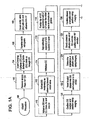
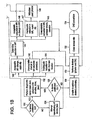
- FIG. 1 is a flow diagram depicting a method of providing direct plication annuloplasty to the mitral valve in a heart such as that depicted in FIG. 2A .
- the procedure begins with a puncture for access to the femoral artery using standard techniques.
- the physician or other practitioner places a catheter sheath introducer (CSI) into the femoral access point using standard techniques. Any known CSI may be used in the procedure with the preferable size being approximately 14 french.
- CSI catheter sheath introducer
- Any known CSI may be used in the procedure with the preferable size being approximately 14 french.
- a crossing catheter, not the subject of the present invention, preferably prolapseable or having a curved tip, and the deflecting guide catheter of the present invention are inserted together in a "stack" formation through the CSI.
- the deflecting guide catheter is inserted through the CSI without a crossing catheter although the use of a crossing catheter is the preferred method.
- the crossing catheter is described herein in greater detail with respect to FIGS.4 and 5 below and the deflecting guide catheter ofthe present invention is described herein in greater detail with respect to FIGS. 6 to11.
- the stacked crossing catheter and deflecting guide catheter are advanced through the arterial system of the patient traversing the aorta of the patient in a retrograde manner at step 106.
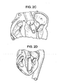
- the aortic valve (AV) is crossed with the crossing catheter and the crossing catheter is advanced into the left ventricle (LV) as depicted in FIG. 2B .
- the deflecting guide catheter is advanced over the crossing catheter through the aortic valve and into the left ventricle as depicted in FIG. 2C .
- the deflecting guide catheter is deflected in a somewhat retroflexed manner as it is advanced approximately toward the mitral valve at step 112 as depicted in FIG. 2D and the crossing catheter is withdrawn at step 114.
- a guidewire may also be used with the crossing catheter and deflecting guide catheter in a three-element stack inserted in the CSI. If a guidewire is used it is advanced first through the arterial system and over the aortic arch followed by the combined stack of the crossing catheter and the deflecting guide catheter. The guidewire is introduced first through the aortic valve followed by the crossing catheter which is preferably oriented into a position between the papillary muscles although this is not necessary. The procedure then continues as in steps 110 and 112 above with the guidewire removed simultaneously with the crossing catheter at step 114.
- step 116 a region of the deflecting guide catheter is seated toward the mitral valve in the apex of the left ventricle as in FIG. 2E .
- the tip of the deflecting guide catheter is advanced up the posterior wall of the left ventricle to a position under the mitral valve, preferably initially placed in the subvalvular groove in the P2 region of the as shown in FIG. 3 .
- the term "annulus" is meant to include regions at or near the annulus.
- the position of the tip of the deflecting guide catheter is confirmed by using an imaging method such as fluoroscopy.
- P2 is the likely target region for a first retainer although depending on the geometery of the mitral valve the first retainer may be placed in region P1 or region P3. Additional retainers may need to be placed in the same or other regions.
- a plication device 400 not the subject of the present invention loaded with one or more retainers is inserted into the deflecting guide catheter and advanced to the tip of the deflecting guide catheter.
- a plication device for use in this method is described in greater detail herein with respect to FIGS. 12 through 14H .
- the rotational orientation of the jaws of the plication device is determined using an imaging method and the jaws are placed in the correct orientation.
- the preferable rotational orientation for the jaws of the plication device is such that both tips of the jaws once opened would represent a "chord" of the arc defined by the mitral valve annulus when pushed into contact with the annulus.
- the plication device is advanced out of the end of the deflecting guide catheter into position under the annulus of the mitral valve as depicted in FIG. 2E .
- the orientation and position of the plication device is reconfirmed at step 128 using an imaging method. Again, if fluoroscopy is used as the imaging method, at least one and preferably two views are be used to confirm orientation and placement of the jaws of the plication device.
- An injection of a known contrast agent either using a separate contrast catheter or through the deflecting guide catheter may be used to help define the line of the annulus as viewed under fluoroscopy.
- a decision is made by the physician whether or not the jaws of the plication device are properly positioned.
- step 134 an attempt is made to reposition the jaws of the plication device.
- step 136 the position of the plication device is evaluated again using an imaging method as described previously and in more detail below. If the plication device is positioned correctly then step 132 and onward are performed as discussed below. If the plication device is not positioned properly after at least one attempt at repositioning at step 134 then step 138 results in a determination that the plication device cannot achieve a desired position and the plication device and deflectable guide catheter are withdrawn from the patient at step 150.
- a diagnostic clamp or plication is performed at step 132.
- the jaws of the plication device are opened as depicted in FIG. 2F
- the plication device is advanced onto the tissue of the annulus of the mitral valve and the jaws are closed as depicted in FIG. 2G .
- the diagnostic plication is evaluated at steps 140, 142 and 144. If the diagnostic plication results in an acceptable change in the mitral valve annulus and/or an acceptable reduction in mitral valve regurgitation then a retainer is applied using the plication device at step 140 and the plication device is released as depicted in FIG. 2H .
- Embodiments of a retainer that may be applied to the tissue are described in greater detail herein with respect to FIGS. 15 .
- the diagnostic plication results in an unacceptable change to the mitral valve then the procedure is abandoned and both the plication device and the deflectable guide catheter are withdrawn from the patient at step 150.
- the diagnostic plication results in an insufficent or inadequate reduction in mitral valve regurgitation (MR) and/or insufficient or inadequate change in the mitral valve then the diagnostic plication is released and an attempt to reposition the jaws of the plication device is performed at step 134.
- MR mitral valve regurgitation
- a determination regarding the impact of the plication on the regurgitation of the mitral valve is made using a method of imaging the flow of blood through the valve such as Doppler echocardiograpy.
- steps 146 , 147 and 148 various decisions are made regarding the procedure and continuation of the procedure.
- the procedure branches to step 150 with the retrieval of the plication device and the deflecting guide catheter.
- step 147 the plication device currently in use is withdrawn if it is a single retainer device and an additional plication device is inserted and the procedure continues from step 122. If the plication device is a multi-retainer device then the procedure continues from step 124 without withdrawal of the plication device. If the determination regarding the impact of the plication on mitral valve regurgitation results in a finding of an adverse result at step 148 then the procedure will likely be abandoned and both the plication device and deflecting guide catheter are removed from the patient at step 150. After removal of the plication device and the deflecting guide catheter, the catheter sheath introducer is removed and the access site is closed at step 152 using known methods.
- Fluoroscopy is one real-time imaging modality that is useful, preferably, where images are taken in at least two planes. Radiopaque markers placed on the distal end of the plication device and/or deflecting guide will aid in determining proper placement.
- a three-dimensional profile of the plication device can be created using x-ray images acquired in at least two planar projections in real-time. Alternatively, rotational angiographic imaging may be used. Additionally, registering pre-acquired CT or MRI image data with the fluoroscopic image will provide additional anatomic data to the physician to aid proper placement of the plication device and retainer or retainer. Similarly, a three-dimensional real-time ultrasound image acquired in real-time may be registered with the fluoroscopic image.
- ICE intracardiac echocardiography
- the ICE image may be produced by an ICE catheter placed inside one of the chambers of the heart such as the right ventricle, left ventricle, left atrium or the right atrium.
- the ICE catheter could be placed inside on of the great vessels of the heart of the patient.
- the ICE catheter may also be placed on the epicardial or pericardial sack surfaces of the heart via a minimally invasive approach such as a sub-xiphoid approach.
- the images of the mitral valve should be taken synchronized to the cardiac cycle.
- Various imaging modalities are also useful in determining whether the plication achieves the desired impact on the function of the mitral valve in real-time or near real-time prior to applying the retainer to the plication.
- Real-time means that the latency period is acceptable to perform the procedure and is preferably no more than 500 milliseconds.
- Color Doppler ultrasound imaging may be used for such a purpose with or without an ultrasound contrast agent being administered to the patient.
- x-ray fluoroscopy could be used in determining the impact of a plication on mitral valve regurgitation by using an x-ray contrast bolus injection into one of the chambers of the heart, preferably the left ventricle.
- Bi-planar angiographic imaging or intra-chamber optical imaging may also be used. If intra-chamber optical imaging is used it is preferable that the deflecting guide catheter further comprise an optical imaging system particularly one that operates in infrared wavelengths.
- Determining a location for the first tissue plication may be based on an optimization plan generated using a three-dimensional functional numerical simulation based on imaging data generated by one or more of the aforementioned imaging method. For example, by analyzing the distribution of annular tissue relative to the location of the primary regurgitant flow through the valve, a primary target for initial plication therapy may be determined. It may be desirable to place the plication at the location of greatest distortion of the annulus due to the pathology of the patient's heart.
- the generation of the optimization plan may be performed prior to step of inserting the crossing catheter.
- the generation of the optimization plan may be performed after the step of applying a retainer to the first tissue plication in order to determine the preferred location for subsequent plication or plications.
- the plications could be made on the atrial surface if a transseptal approach is used. This can be accomplished by accessing the right atrium using SVC or IVC venous approaches. Then access the left atrium is accomplished using a standard transseptal puncture/access kit such as a Brockenbrough transseptal needle kit. The deflecting guide catheter would then be introduced through the puncture and deflected such that the tip pointed towards the annulus of the mitral valve. The subsequent steps and devices for a plication annuloplasty procedure would then be the substantially the same as set forth above except that the approach is from the atrial side of the mitral valve rather than the underside.
- FIG. 4 is a perspective view of a crossing catheter 200 for use in the procedure described in the present application.
- Crossing catheter 200 is comprised of a body portion 210 having a proximal end 210a and a distal end 210b. Connected to proximal end 210a are a female luer lock 216 and a Tuohy-Borst hemostasis valve 214. At the distal end 210b portion is attached which is preferably a pigtail 218 or has a "J" configuration (not shown).
- Pigtail 218 is approximately 2.0 centimeters or less in diameter. In FIG. 4 pigtail 218 is attached to body portion 210 at a splice location that is approximately 4 centimeters from the distal end of the device. Pigtail 218 is attached to body portion 210 using heat bonding as the body portion 210 and pigtail 218 re made from the same or similar material. Pigtail 218 is comprised of a polymer, prefereably, Pebax ® polyether block amide having a durometer of approximately 55D if comprised of one layer or two layers having durometers of approximately 40D in the outer layer and 55Din the inner layer. Body portion 210 may be comprised of one layer having a durometer between 55D and 72D or may have two layers.
- the preferred durometers are 70D for the outside and 63D for the inside.
- the total length of the body portion and pigtail together is approximately 149 centimeters and should extend beyond the deflecting guide catheter when fully inserted into the deflecting guide catheter thus the length of the crossing catheter may vary depending on the length of the deflecting guide catheter used.
- the location at which the pigtail may be attached to the body portion may also vary from 3 centimeters to approximately 44.5 centimeters from the distal tip of the crossing catheter 200.
- the crossing catheter may also be comprised of one material from the body portion through the pigtail. In such a case the use of an outer material with a durometer of 55D and an inner material with a durometer of 40D is preferred.
- a flat wire braid 212 of flat wires of approximately 0.03 mm (0.001") by 0.08 mm (0.003”) may be embedded in the polymer comprising the proximal portion of body portion 210 in order to provide extra stiffness and torqueability.
- An inner layer 211 of PTFE provides a lubricious inner coating and a separation between the polymer and the inner lumen.
- the stiffness of the pigtail portion of the crossing catheter is chosen so that a standard guidewire such as the Cordis Emerald 0.89 mm (0.035”) guidewire will open up the pigtail yet will return to the pigtail shape when retracted.
- a standard guidewire such as the Cordis Emerald 0.89 mm (0.035) guidewire will open up the pigtail yet will return to the pigtail shape when retracted.
- Such a guidewire is placed in the guidewire lumen defined by the inner layer 211 of the crossing catheter and should extend through the entire length of the crossing catheter.
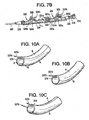
- Crossing catheter 200 may be used with or without a guidewire as described above and is preferably used in conjunction with the deflecting guide catheter of the present invention, depicted in FIGS. 6 through 10A-C .
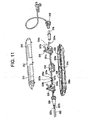
- Deflecting guide catheter 300 is comprised of a handle 310 and a body portion 350.
- FIG. 7A is an exploded view of an embodiment of the handle 310 depicting the internal components of the handle and
- FIG. 7B is a perspective view of the internal components of handle 310 as assembled.
- Handle 310 is comprised of upper handle shell 312 and lower handle shell 314 which are made of a durable moldable polymeric material such as polycarbonate or other similar material and are designed to mate with one another in a snap fit arrangement.
- a hemostasis valve 316 which is adapted to fit onto the proximal handle tip 318.
- Hemostasis valve 316 may be of any known design for such a valve such as a tuohy-borst type valve.
- Proximal actuator assembly 324 is comprised of a thumb actuator 324a that is adapted to be inserted through slot 313 in the upper handle shell 312.
- a two-piece construction with a thumb cap 325 may be used to facilitate assembly if slot 313 is narrow.
- the thumb actuator 324a and optional thumb 325 cap are used to cause forward motion in the proximal direction of puller wire 327a.
- Such motion is retained as the prong or prongs 324e biased by spring 324d around pivot point axel pin 324c engages the teeth 322a in proximal rack 322.
- proximal motion of the proximal actuator assembly 324 and the associated puller wire 327a causes the deflection of the distal end of the deflecting guide catheter 300. If the user desires to have distal motion of the proximal actuator assembly 324 then the user pushers release trigger 324b which counters the bias of spring 324d thereby releasing prong or prongs 324e from engagement with the teeth 322a of the proximal rack 322.
- Proximal hypotube 331a provides a passageway for puller wire 327a and prevents kinking of the wire.
- Distal hypotube 331b is designed to telescope inside hypotube 331a.
- crimp tube 334a At the end of puller wire 327a are fixedly attached crimp tube 334a and a floating crimp tube stop 334b that prevents the crimp tube from being embedded in the proximal end of the actuator assembly.
- the user may then move the actuator assembly distally thereby changing the deflection of the distal end of the deflecting guide catheter. Movement of the actuator assembly may be made by the physician using something other than his or her thumb and the terms “thumb actuator” and “thumb cap” are not meant to be limiting.
- Handle 310 further comprises a distal actuator assembly 328 having a similar thumb actuator 328a, release trigger 324b, axel pin 324c, spring 328d and prong 328e.
- Optional thumb cap 329 is affixed over thumb actuator 328a.
- the distal actuator assembly 328 is connected to a second pullerwire 327b (shown in FIG. 11 ) that enables the user to cause deflection of the distal end of the deflecting guide catheter.
- the first and second puller wires are attached (through known methods and means such as welding, brazing or adhesives) to anchor bands 385a and 385b that are embedded in the distal region 360 of the body portion 350 of the deflecting guide.
- the puller wires and their respective anchor band connection points may also be arranged so that they are not next to one another (in an axial manner) but so that each provides motion of the distal end in another plane or in the other direction within the same plane.
- the second puller wire and actuator are not necessary if it is only necessary to provide one type of movement in the deflecting guide catheter.
- additional thumb actuator assemblies coupled to puller wires and anchor bands may be added in a similar manner to the catheter.
- the second distal actuator assembly has the same components as functions in the same manner as the proximal actuator assembly.
- distal actuator assembly 328 requires a passageway for passage of the first puller wire 327a through the distal assembly which passage is aided by hypotube 331b.
- the second puller wire 327b ends at the distal end with a similar crimp tube 335a and crimp tube stop 335b.
- Nose cone 330 provides a transition between the handle shell 312/314 and the proximal region 390 of the body portion 350.
- Acuator assemblies 324 and 328 and racks 322 and 326 are comprised of a polymeric material such as polycarbonate. Such assemblies could be made of machined or molded metal, such as aluminum, although that would result in a higher cost and weight device.
- Racks 322 and 326 with teeth 322a and 326a may be separate components or may preferably be molded into the lower handle shell 314 as depicted in the alternative embodiment shown in FIG. 11 .
- Handle insert 338 is used as a divider between the two racks 322 and 326 and provides a support for proximal hypotube 331a.
- Puller wires 327a and 327b are preferably high tensile strength 304 stainless steel (e.g. tensile strength greater than 2000 MPa (300ksi)) but may also be made of other high strength materials such as MP35N, other stainless steel, or woven fibers such as Kevlar or Vectran.
- Puller wires 327a and 327b are preferably a single, solid core high tensile strength 304 stainless steel wire (e.g. tensile strength greater than 2000 MPa (300ksi)) of approximately 0.20 mm (0.008") in diameter but may also be made of other high strength materials such as MP35N, other stainless steel, or woven fibers such as Kevlar or Vectran.
- an anchor band 385a or 385b is embedded in the wall of the catheter body at the point of anchoring. Changing the location of the anchor band along the axial length of the catheter body will change the deflection profile of the deflectable guide catheter.
- Body portion 350 of deflecting guide catheter 300 is depicted in FIG. 8 and FIGS. 9A and 9B .
- Body portion is separated into four regions: distal region 360, intermediate distal region 370, main intermediate region 380 and proximal region 390.
- Distal region 360 at the distal end is approximately 3.5 centimeters in length and is made of a polymeric material such as Pebax ® with a durometer of between 25D and 40D and preferably35D.
- a radiopaque material such as bismuth subcarbonate is added to the material in distal region 360 to enable the distal region 360 of the deflecting guide catheter 300 appear in fluoroscopy and other imaging procedures.
- the wall thickness in the distal region 360 is between approximately 0.30 mm and 0.36 mm (0.012 and 0.014 inches).
- the anchor band 385a for the first puller wire is embedded near the distal end of distal region 360 and the anchor band 385b for the second puller wire is embedded near the proximal end of distal region 360 or at the distal end of region 370.
- This arrangement may also be reversed so that the anchor band for the first puller wire is embedded near the proximal end of the distal region and the anchor band for the second puller wire is embedded near the distal end of the distal region. It is also possible to place the anchor bands next to one another rather than longitudinally separated as depicted in the embodiment shown.
- the anchor bands are preferably tubular metal bands preferably placed between the lubricious liner 365 and the braid 375 although it could be placed above the braid in an alternative embodiment.
- Each anchor band is made of 304 stainless steel and each puller wire is attached to its respective anchor band using welding or other means for joining metal that is known in the art.
- FIG. 9C depicts an alternative arrangement of the proximal anchor band 385a in which a notch or lumen is placed in the anchor band to allow the passage of the second puller wire 327b in braid reinforced puller wire lumen 395b through at least a radial portion of the anchor band. Puller wire 327a is attached to anchor band 385a. This arrangement enables the catheter to have a more symmetrical and smaller profile at this point.
- the internal diameter of distal region 360 as well as the entire body portion is defined by a lubricious liner 365 preferably PTFE that has an interior diameter of approximately 3.23 mm (0.127 inches) and is approximately 0.05 mm (0.002 inches) thick.
- the outer diameter of distal region 360 is approximately 4.37 mm (0.172 inches) between the anchor bands and approximately 4.47 mm (0.176 inches) at the location of the distal band.
- a braid 375 of wires having a diameter between 0.06 mm and 0.08 mm (0.0025 and 0.003 inches) in either a 1 over 1,1 over 2 under 2 or 2 over 2 pattern is embedded in the polymeric wall of the catheter from the proximal region 390 to the distal region 360.
- atraumatic tip 362 comprised of approximately 33.5% 25D Pebax ®, approximately 6.4% 55D Pebax® and approximately 60% bismuth subcarbonate and having a slight taper toward its distal end.
- the atraumatic tip is optional although preferred in order to avoid tissue damage during insertion into the vessels of the patient.
- the distal region 360 is comprised of a polymeric material having a higher durometer than both the atraumtic tip 362 and the intermediate distal region 370.
- This stiffer distal region between anchor bands 382a and 385b will enable the deflection profile of the deflecting guide catheter to be altered in such a way as to allow the deflected shape of the catheter to better match the shape of the target anatomy for the device.
- an alternative embodiment adds an additional region of material between the distal and intermediate distal regions, which is of a durometer different from that of both adjacent regions. This is also done to alter the deflected shape of the catheter in a favorable manner and create a region which either deflects much more or much less (depending if the durometer is lower or higher than adjacent regions) than the adjacent regions.
- Intermediate distal region 370 is comprised of the same type of polymeric material but has a higher durometer of between 35D and 55D to provide a stiffer region. Intermediate distal region 370 is between approximately 2.8 and 4.0 centimeters in length and contains the same lubricious liner 365 and wire braid 375 as the distal region. The wall thickness in the intermediate distal region is similarly between 0.30 mm and 0.36 mm (0.012 and 0.014 inches) and the outer diameter is approximately 4.37 mm (0.172 inches).
- Main intermediate region 380 has a slightly smaller outer diameter at 4.22 mm (0.166 inches) but has the same lubricious liner and braid as the other regions.
- the main difference in this region is the higher durometer of between 55D and 63D for the polymeric material used in order to provide increasing stiffness.
- the main intermediate region is approximately 20 to 30 centimeters in length, preferably 20 centimeters.
- Proximal region 390 has a similar composition in that the outer diameter is the same as the immediately prior region.
- the durometer in this region is increased to approximately 72D providing even greater stiffness and the length of this region is approximately 73 to 90 centimeters, preferably 88 centimeters.
- the lubricious layer 365 and braid 375 are the same.
- first and second anchor bands 385a/385b run two braid reinforced tubes 395a/395b of approximately 0.22 mm (0.0088) inches in internal diameter which house the first and second puller wires respectively.
- One puller wire, anchor band and reinforced tube could be used instead of two.
- the braid may be changed to a different size or cross section (such as elliptical) wire and braid type.
- the polymeric material of the outer body may be varied as depicted in FIGS. 10A-10C . In FIG. 10A materials having two different durometers are used in an alternating fashion.
- Material A is used in two circumferential portions opposite one another while material B is used in two other opposing circumferential portions.
- the durometer of material A may be greater than the durometer of material B or vice versa depending on the deflection characteristics desired.
- Use of two different durometer materials in such a way provides the benefit of balancing the ability or ease of the catheters to deflect in a particular direction with the requirement for lateral stiffness.
- FIG. 10B two circumferential portions of material A and material B are used to provide a certain desired deflection characteristic.
- FIG. 10C the use of two different durometer materials is used in conjunction with placement of the puller wires 327a and 327b at different places along the circumference of the body portion.
- the first puller 327a wire is attached to the first anchor band at a position in the first material and the second puller wire 327b is attached to a second anchor band at a position in the second material.
- the distal end of the deflecting guide catheter would deflect in two different planes substantially perpendicular to one another.
- the planes of deflection are primarily determined by the relative placement of the puller wire lumens.
- the deflecting guide catheter may further comprise a magnetic based location sensor such as those manufactured by Biosense Webster for sensing the location and orientation (six degrees of freedom) of the distal end of the deflecting guide catheter and for providing location information that may be registered with other preaquired or real-time images or otherwise used to depict the location of the distal end of the deflecting guide catheter on a real-time display map of the heart.
- a magnetic based location sensor such as those manufactured by Biosense Webster for sensing the location and orientation (six degrees of freedom) of the distal end of the deflecting guide catheter and for providing location information that may be registered with other preaquired or real-time images or otherwise used to depict the location of the distal end of the deflecting guide catheter on a real-time display map of the heart.
- Systems such as the Carto® system produced by Biosense Webster would be useful for this purpose.
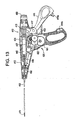
- FIG. 12 is an elevational view of a plication device 400 , not the subject of the present invention, for use in the method of treating mitral valve.
- Plication device 400 is comprised of a handle assembly 410 and a distal assembly 450 having an elongate shaft 452 at the distal end of which are attached a plication assembly with an end effector 520.
- FIG. 13 is an elevational view of the internal components of the handle assembly 410.
- Handle assembly 410 is comprised of two polycarbonate shell portions - right handle shell 412 and left handle shell 414 that are adapted to house the internal components of the handle assembly.
- Internal to handle assembly 410 reside crank assembly 420 for advancing a retainer stored in the distal portion of the elongate shaft 452.
- the firing assembly 420 is comprised of counter gear 421, drive gear assembly 422 , idle gear 423 , and crown gear 424. Firing assembly 420 is coupled to the firing knob 430 , shown in FIG. 12 , which is rotatably coupled to left handle shell 414. While not shown, a second firing knob can be disposed on the opposed side of the handle assembly 410 to allow a user to selectively rotate either knob. Either firing knob further comprises a anti-backup leaf spring (not shown) that prevents the knob from turning in the reverse direction and a trigger lockout spring (not shown) that prevents the knob from turning until the trigger is fully closed or engaged. Continuing to refer to refer to FIG.
- the gears 421, 422, 423 and 424 of firing assembly 420 are configured to rotate in response to rotation of the firing knob 430.
- the gears communicate with one another to cause corresponding rotation of pinion assembly 437 and drive shaft 436.
- Drive shaft 436 is mated to a proximal end of firing control wire 490.
- End cap 460 has a plurality of ridges dispersed around it circumference to aid the grip of the user.
- the trigger 416 is pivotally mounted within the handle assembly 410 by a pivot pin 417, and includes a distal portion having a thumb grip formed therein and a proximal extension arm 418.
- the trigger 416 also includes a latch 419a that is adapted to be received in the latch receiver 419b in the handle assembly to lock the trigger into a closed position.
- the extension arm 418 is coupled to a shuttle assembly 440 that moves between proximal and distal positions within the housing assembly 410.
- the shuttle assembly 440 can have various configurations and it can include various features, such as an overload mechanism. The particular configuration of the shuttle assembly 440 is described in more detail in U.S. Patent Publication No. 2005/02779954 .
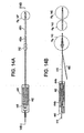
- FIGS. 14A and 14B Some of the internal parts of the shuttle assembly 440 including spring pin 446 , force limiting spring 442 , spring caps 444a and 444b are shown in FIGS. 14A and 14B .
- the shuttle assembly 440 is coupled to a proximal portion of end-effector control wire 510, which extends through the elongate shaft 452.
- the distal end of the end effector control wire 510 mates (preferably by welding) to wire connector 542, which is shown in FIG. 14D
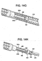
- the wire connector 542 is positioned as shown in FIG. 14G proximal to the end effector 520, i.e., the clevis 522 and jaws 524a and 524b.
- Wire connector 542 is also welded to two parallel pull wires 544a and 544b that run from wire connector 542 through nut 550 and terminate in holes at the proximal end of jaws 524a and 524b respectively.
- wire connector 542 splits the force of end effector control wire 510 into two forces for controlling the opening and closing of the jaws.
- Other arrangements are possible if, for example, it would be desired to have one fixed jaw and one movable jaw rather than two movable jaws. It is also possible to have some passive articulation of the distal jaws 524a and 524b by having the pull wires 544a and 544b pass through wire connector 542 as depicted in FIG.
- Distal jaws 524a and 524b rotate around pivot point rivots 523a and 523b respectively.
- the firing control wire 490 extends through the elongate shaft 452 and through a bore formed in the wire connector 542 and is threadably mated to a threaded bore in nut 550.
- the distal end of the firing control wire 490 extends into a retainer pusher 554 set in a retainer pusher sleeve 556, both of which are shown in FIG. 14E and which is described in more detail in US. Publication No. 2005/0277954 .
- rotation of the firing knob 430 is effective to rotate the firing control wire 490.
- the firing control wire 490 is threadably mated to the nut 550 , which is fixed between the proximal and distal portions of the elongate shaft 452 , the threaded bore in nut 550 will cause the firing control wire 490 to move distally through the elongate shaft 452, thereby advancing the retainer pusher 554 in a distal direction.
- the retainer pusher 554 is positioned proximal to one or more retainers 500 stored within a garage 532 in the distal portion of the elongate shaft 452 , and thus distal movement of the pusher 554 will advance the retainers 550 through the shaft 452 to position the distal most retainer within the jaws 524a and 524b of the end effector 520.
- a person skilled in the art will appreciate that a variety of other techniques can be used to advance a plurality of retainers through the elongate shaft and to position a retainer within the jaws.
- the coil connector 512 which is made of a metal, preferably brass, and is used as a means for connecting the proximal portion 452a of elongate shaft 452 to the handle assembly.
- Dual lumen inner sheath 560 has lumens for end-effector control wire 510 and firing control wire 490.
- Filler tube connector 562 is used to connect the coil connector 512 to the elongate shaft 452 and is glued to coil connector 512 and elongate shaft 452 using an adhesive glue such as cyanoacrylate.
- Elongate shaft 452 is broken into proximal shaft section 452a and distal shaft section 452b.
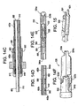
- Proximal shaft section 452a is preferably nitinol and has a dovetail laser pattern.
- Distal shaft section 452b is preferably stainless steel and has a similar dovetail pattern cut through the wall of the shaft. Other patterns could also be used such as a helical cut as shown in FIG. 16A.
- FIG.16B depicts another variation of the plication device where the proximal shaft section is similar to that above but the nut is placed significantly more distally and the stainless steel distal shaft section with a dovetail pattern is replaced with a helical cut creating a ribbon coil.
- FIG. 16C depicts the placement of the nut and the dovetail patterns of the proximal and distal shaft portions discussed with respect to FIGS. 14A-F above.
- FIG. 16D depicts the passively articulating jaws of the alternative embodiment discussed above.
- Retainer 500 is comprised of stainless steel or other biocompatible material such as MP35N, platinum, nitinol and cobalt chromium or alloys thereof.
- the helical retainer may also be made of a or polymeric material such as one made of poly lactic acid (PLA) and/or poly glycolic acid (PGA).
- the retainer is comprised of a metal alloy with the preferred embodiment containing at least a trace of an element having an atomic number greater than 53 such as platinum to enhance visibility of the retainer under fluoroscopy. Additionally, a sufficient wall thickness should be chosen to ensure visibility under fluoro.
- the shape of the tip of the distal jaws of the plication device also have an alignment feature when viewed under fluoro that allows the viewer to determine which of 2 orientations (0/180 or 90/270) the jaws are in. In a 0/180 orientation the tip of the jaws form a circle as depicted in FIG. 14F . In a 90/270 orientation the tip of the jaws form a minus as depicted in FIG. 14B .
- the retainer 500 is preferably "C" shaped with elongated legs which may vary in length depending on the depth of tissue to be penetrated and the number of retainers that are desired to be housed within the garage of the plication device.
- the tips 501 are designed to be folded by the distal tips of the jaws of the end effector during the process of advancement to prevent the retainer from backing out or being pulled out of the plicated tissue.
- the retainer could be coated with one or more pharmacologically active agents such as heparin for the purpose of reducing thrombotic potential.
- the plication device may further comprise a magnetic based location sensor such as those manufactured by Biosense Webster for sensing the location and orientation (six degrees of freedom, x, y, z, roll (Xrot), pitch (Yrot) and yaw (Zrot)) of the distal end of the deflecting guide catheter and for providing location information that may be registered with other preaquired or real-time images or otherwise used to depict the location of the distal end of the deflecting guide catheter on a real-time display map of the heart.
- Systems such as the Carto® system produced by Biosense Webster would be useful for this purpose.
- the incorporation of the magnetic based location sensor near the distal tip of the plication device enables precise orientation of the jaws in order to facilitate placement of the jaws and plication of the tissue.
- the magnetic location sensors would be placed proximal the distal end of the jaws of the plication device due to shielding if such sensors were placed in the jaws themselves.
- Location information is then transmitted through electrical conductors to circuitry in the handle of the plication device which is electrically connected to a Carto® mapping system.
- the Carto® mapping system will then use the location information from the magnetic location sensors in order to extrapolate the location and layout of the distal end of the plication device.
- a sensor should also be placed in the handle of the plication device that would provide a signal to the Carto® system indicative of the open/closed position of the jaws. With this information the Carto® system will be able to display a real-time image of the heart and the location of the distal end of the plication device within the left ventricle, etc.
- the devices disclosed herein can also be designed to be disposed of after a single use, or they can be designed to be used multiple times. In either case, however, the device can be reconditioned for reuse after at least one use. Reconditioning can include any combination of the steps of disassembly of the device, followed by cleaning or replacement of particular pieces, and subsequent reassembly.
- the device can be disassembled, and any number of the particular pieces or parts of the device can be selectively replaced or removed in any combination.
- the device can be reassembled for subsequent use either at a reconditioning facility, or by a surgical team immediately prior to a surgical procedure.
- reconditioning of a device can utilize a variety of techniques for disassembly, cleaning and/or replacement, and reassembly. Use of such techniques, and the resulting reconditioned device, are all within the scope of the present application.
Description
- the present invention is directed to a deflecting guide catheter for use in a system and method for treating mitral valve regurgitation in the heart of a patient using direct plication annuloplasty.
- Catheter based devices are used to treat a wide variety of medical problems in a minimally invasive manner. Catheters are used to place and expand angioplasty balloons used to widen veins and arteries narrowed by plaque. Small scaffolds called stents have been introduced into the vasculature using catheter-based systems in order to prevent the restenosis of such vessels. One of the problems that a catheter based device and system could be used to treat in a minimally invasive manner is mitral valve regurgitation, however, no commercially successful device for the treatment of mitral valve regurgitation in such a manner currently exists.
- Mitral valve regurgitation is the backflow of blood from the left ventricle into the left atrium due to an improper alignment of the leaflets of the mitral valve thereby causing an imperfect closure of the valve. A gap between the anterior leaflet and posterior leaflet of the mitral valve is created by the improper closure providing a conduit for blood to flow through the mitral valve in a retrograde manner from the left ventricle to the left atrium. This gap may be a congenital defect or may be caused by disease, i.e., ischemic or idiopathic cardiomyopathy and/or intrinsic degenerative disease of components of the mitral valve apparatus. One type of condition, congestive heart failure (CHF), causes the heart to enlarge. In an enlarged heart the walls of the left ventricle are expanded or dilated which causes the papillary muscles to be displaced downward and/or outward resulting in a tethering of the chordae tendineae and subsequent tethering/pulling on the leaflets. Also, with CHF, the mitral annulus is dilated. The combination of the dilated annulus and the tethering on the leaflets prevents the leaflets from closing properly, thereby causing the problematic gap in the mitral valve. The resultant backflow through the mitral valve reduces the efficiency of the heart resulting in a need for the heart to beat faster and/or more forcefully in order to produce the same amount of blood flow. Mitral valve regurgitation may be asymptomatic in some patients but in other patients the reduction in blood flow and the resultant strain on the heart could result in arrhythmias, heart attack and possibly death.
- The preferred current treatments for mitral valve regurgitation require open-heart surgery and/or the use of endoscopic techniques that are difficult for the surgeon and potentially dangerous for the patient. In one method of treatment, porcine heart valves or mechanical heart valves are used to replace the damaged or defective mitral valve. Such treatments require the use of open-heart surgery to accomplish the implantation. Such heterologous valves may be used in humans but often wear-out prematurely and additional open-heart surgery is required to replace such valves with additional heterologous or mechanical valves. Mechanical valves have been developed which may also be used as a replacement for a defective mitral valve, however, the implantation of a mechanical valve usually indicates long-term anti-coagulant therapy to prevent clots from developing around the valve that could lead to a dangerous embolism. Long-term anticoagulant treatment causes other problems such as unwanted internal and external bleeding and possibly strokes.
- Another open-heart surgical procedure for treating functional mitral valve regurgitation is annuloplasty. In an annuloplasty procedure, a generally "D" shaped annuloplasty ring is implanted on the mitral valve annulus to reduce the size of the stretched mitral valve annulus, most importantly, the septal-lateral dimension and improve closing (or coaptation) of the valve thereby reducing regurgitation. The surgeon surgically attaches, i.e., sews, the annuloplasty ring to the mitral valve on the atrial side of the mitral valve. The annuloplasty ring is sewn to the annulus on a top portion (i.e., the atrial side) of the mitral valve. Once implanted, tissue generally grows over the annuloplasty ring, and a line of contact between the annuloplasty ring and the mitral valve will essentially enable the mitral valve to appear and function as a normal mitral valve by reestablishing coaptation of the mitral valve leaflets but the durability of the effect is variable and may decline within six months after the procedure. Although a patient who receives the annuloplasty ring may be subjected to anti-coagulant therapies, the therapies are not extensive, as a patient is only subjected to the therapies for a matter of weeks, e.g., until tissue grows over the annuloplasty ring.
- A second open-heart surgical procedure used in the treatment of degenerative mitral valve regurgitation is the Alfieri stitch procedure which the uses an edge-to-edge suture in the mitral valve. An edge-to-edge stitch is used to stitch together an area at approximately the center of a gap defined between the anterior and posterior leaflets of the mitral valve. Once the stitch is in place, the stitch is pulled in to form a suture that holds the anterior leaflet against the posterior leaflet. By reducing the size of the gap between the anterior leaflet and the posterior leaflet, the amount of leakage through the mitral valve may be substantially reduced. Durability has been a concern for Alfieri procedures done without the addition of an annuloplasty ring. In addition, use of the edge-to-edge procedure is only indicated in certain degenerative pathologies where the primary abnormality or gap between the leaflets is centrally located.
- Another method of treating mitral valve regurgitation is the implantation of a ventricular assist device. Such devices are expensive and difficult to implant and require the patient to use anti-coagulant therapy indefinitely. Long-term use of anti-coagulant therapy may result in unnecessary bleeding and strokes. Such ventricular assist devices are, therefore, indicated for use only in patients that would likely not survive without their use and are used to keep patients alive who are candidates for heart transplant surgery. Left ventricular assist devices are a "bridge" therapy rather than a final therapy.
- While such invasive surgical procedures have under certain circumstances been shown to be effective in the treatment of mitral valve leakage, invasive surgical procedures often have significant drawbacks. Any time a patient undergoes open-heart surgery, there is a risk of infection. Opening the sternum and using a cardiopulmonary bypass machine has also been shown to result in a significant incidence of both short and long term neurological deficits.
- Some minimally invasive procedures have been developed to treat mitral valve regurgitation but, to date, none have become commercially successful standard procedures. United States Patent No.
6,619,291 to Hvlaka et al. discloses a minimally invasive method of performing annuloplasty including inserting an implant into a left ventricle and orienting the implant in the left ventricle substantially below the mitral valve. The implant and tissue around the mitral valve are connected and tension is provided to the implant in order to substantially reduce an arc length associated with the mitral valve. - In United States Patent No.
6,718,985 and7,037,334 to Hvalaka et al. a series of plications near the mitral valve are created by T-bars that are threaded together to reshape the mitral valve. In United States Patent No.7,166,127 a catheter based system for treatment of mitral valve regurgitation uses a retainers adapted to be secured to the annulus of the mitral valve with flexible tensile members coupled to the retainers. A crimping device deployable through the catheter compresses a crimp onto the flexible tensile members after they are pulled toward one another to reduce the circumferential length of the annulus. In this system the number of permanent implants required in order to achieve an initial effect, and commitment to these implants before success of effect is able to be determined are serious drawbacks. - In United States Patent Application Publication No.
2007/0093857, Rogers et al. describes a device and method for the treatment of mitral valve regurgitation using a minimally invasive procedure in which plications are made proximate the mitral valve of the patient and a retainer is placed to hold the plication. - United States Patent Application No.
2007/0032797 discloses a device for reducing the size of the stomach having a corkscrew-shaped anchor for placement in the gastric wall. - United States Patent Application No.
2007/0025737 to Messerly et al. discloses a surgical retainer having a generally helical shape and a device having jaws for grasping tissue into which the helical retainer may be driven. - United States Patent Application No.
2007/0055335 discloses an electrode probe having a corkscrew-shaped distal tip for use in cardiology applications. United States Patent Application No.2007/0265610 to Thapliyal discloses a cardiac ablation system including an ablation catheter having an anchor adapted to support the ablation catheter within an atrium of a heart and an ultrasound emitter disposed radially outward from a rotation axis and from the anchor, and a control mechanism adapted to rotate the ultrasound emitter about the rotation axis and to provide ablation energy to the ultrasound emitter to ablate heart tissue. - The need remains for a device and method for treating mitral valve regurgitation that can be used efficiently and effectively in a minimally invasive procedure and that provides the physician with the ability to know that the procedure has resulted in the desired effect prior to removing the device from the patient thereby reducing the need for and expense of repeat procedures. Such a procedure should provide the physician with the ability to changes the effect on the mitral valve during the procedure before taking an irreversible action.
- The deflecting guide catheter of the present invention may be provided in a system and method for the treatment of mitral valve regurgitation. The method, not the subject of the present invention, preferably uses a femoral retrograde approach of crossing the aortic valve. Access to the left ventricle is achieved through the aortic valve using the standard retrograde femoral artery approach utilizing a rounded crossing catheter (CC) preferably with a "J" or pigtail configuration. The deflecting guide catheter is then sent over the crossing catheter into the left ventricle. When the distal end of the deflectable catheter is in the left ventricle the crossing catheter is removed. The deflectable guide is preferably, but need not be, positioned between the papillary muscles with the distal segment lying along the posterior wall of the left ventricle and its tip is pointing towards the underside of the posterior mitral valve annulus. A plication device, not the subject of the present invention, is then introduced through the deflectable catheter and is advanced out of the distal end of the deflectable catheter and is directed at the underside of the mitral valve, more preferably into the subvalvular groove and positioned so as to be able to grasp and plicate the tissue of the mitral valve at or near the annulus.
- A test plication of the mitral valve annulus is created and the appropriateness of the plication is examined using imaging means such as TEE, ICE, TTE or fluoroscopy with or without contrast injection. If the plication is determined to be appropriate then a retainer is applied to the plication to retain the tissue in the plicated state. If the plication is not satisfactory then a retainer is not applied and the jaws of the plication device are released and the plicator is repositioned to plicate a different tissue target at or near the annulus of the mitral valve. Such "test" plications may be repeated a number of times prior to deploying the retainer.
- If a single plication and retainer do not sufficiently reshape the mitral valve to correct the regurgitation then the original deflectable guide is repositioned and a second plicator with a retainer is introduced into the delivery guide and positioned and used in the same manner. Alternatively, a multi-retainer plicator can be used to provide the second or third retainers as necessary during the procedure without requiring the removal and reintroduction of the plication device. Once satisfactory changes in the annular geometry of the mitral valve and concomitant reduction in mitral valve regurgitation is achieved then the plication device and the deflectable guide are fully withdrawn and the femoral access site is closed using conventional closing techniques.
- Four components comprise the total system for percutaneous direct plication annuloplasty. The first is a prolapsable or curved tip crossing catheter, not the subject of the present invention, preferably having a "J" or pigtail configuration. This may be used with or without a guidewire. In either case the crossing catheter is inserted in a stack or telescoped configuration with the second component, the deflecting guide catheter of the present invention, within which the crossing catheter is initially telescoped or stacked. The deflecting guide catheter is used to provide a means for guiding the plication device into proper position on the underside of the mitral valve preferably at the subvalvular region of the mitral valve at or near the annulus. The third component of the system is a plication device, not the subject of the present invention, that has an end effector having opposing members at least one of which can be manipulated to open. The plication device is used to grasp tissue and also contains at least one retainer to retain the tissue in the plicated form if desired. The retainer in the preferred embodiment is a "C" shaped retainer having an end portion and two substantially perpendicular prongs that are pushed into the plicated tissue. The ends of the prongs may be compressed to increase the pressure on the plicated tissue and to prevent the retainer from being dislodged from the plicated tissue.
- The present invention provides a deflecting guide catheter for guiding a medical device through a lumen of a patient during a medical procedure as set out in the appended claims.
-
-
FIGS. 1A and1B are a flow diagram describing a method of treating mitral valve regurgitation. -
FIGS. 2A-H depict the stages of the various steps of the method of treating mitral valve regurgitation in accordance withFIGS 1A and1B . -
FIG. 3 depicts the plication regions in the method of treating mitral valve regurgitation in accordance with the method ofFIGS 1A and1B . -
FIG. 4 is a perspective view of a crossing catheter for use in treating mitral valve regurgitation in accordance with the method ofFIGS 1A and1B . -
FIG. 5 is a cutaway view of a portion of the body of the crossing catheter ofFIG. 4 . -
FIG. 6 is an elevational view of a deflecting guide catheter in accordance with the present invention for use in treating mitral valve regurgitation in accordance with the method ofFIGS 1A and1B . -
FIG. 7A and7B are an exploded view and a perspective view respectively of the components of a handle for the deflecting guide catheter ofFIG. 6 . -
FIG. 8 is an elevational view of the body portion of the deflecting guide catheter ofFIG. 6 . -
FIGS. 9A and 9B are cross-sectional views of the body portion of the deflecting guide catheter ofFIG. 8 taken through lines A and B respectively.FIG. 9C is a cross-sectional view of an alternative embodiment of the arrangement of the anchor bands in the distal tip of the deflecting guide catheter. -
FIGS. 10A-10C are perspective views of the body portion of other deflecting guide catheters, which may be adapted in accordance with the present invention for use in treating mitral valve regurgitation -
FIG. 11 is an exploded perspective view of another handle and internal components used in a deflecting guide catheter in accordance with the present invention. -
FIG. 12 is an elevational view of a plication device for use in the method ofFIGS 1A and1B . -
FIG. 13 is an elevational view of the plication device ofFIG. 12 with a portion removed to expose the internal components. -
FIG. 14A is an elevational view of the plication device ofFIGS. 12 and13 from the shuttle assembly to the distal end. -
FIG. 14B is a cross sectional view of the portion of the plication device ofFIG. 14A taken through line A-A. -
FIG. 14C is an enlarged view of proximal end section D of the cross-sectional view of the portion ofthe plication device ofFIG. 14B . -
FIG. 14D is an enlarged view of distal section C ofthe cross-sectional view of the portion of the plication device ofFIG. 14B . -
FIG. 14E is an enlarged view of the distal tip section B of the cross-sectional view of the portion of the plication device ofFIG. 14B . -
FIG. 14F is an enlarged planar view ofthe distal tip of the plication device ofFIG. 14A . -
FIG. 14G is a detailed perspective view depicting the coupling of the end-effector control wire to the distal puller wires. -
FIG. 14H is a detailed perspective view depicting the coupling of the end-effector control wire to the distal puller wires in a plication device having passive articulation. -
FIG. 15 is a perspective view of a retainer for use in a plication device for use in the method ofFIGS 1A and1B . -
FIGS. 16A-16D are elevational views of the distal end of various plication devices for use in the method ofFIGS 1A and1B . -
FIG. 1 is a flow diagram depicting a method of providing direct plication annuloplasty to the mitral valve in a heart such as that depicted inFIG. 2A . Atstep 100 the procedure begins with a puncture for access to the femoral artery using standard techniques. Atstep 102 the physician or other practitioner places a catheter sheath introducer (CSI) into the femoral access point using standard techniques. Any known CSI may be used in the procedure with the preferable size being approximately 14 french. At step 104 a crossing catheter, not the subject of the present invention, preferably prolapseable or having a curved tip, and the deflecting guide catheter of the present invention are inserted together in a "stack" formation through the CSI. Alternatively, the deflecting guide catheter is inserted through the CSI without a crossing catheter although the use of a crossing catheter is the preferred method. The crossing catheter is described herein in greater detail with respect toFIGS.4 and 5 below and the deflecting guide catheter ofthe present invention is described herein in greater detail with respect toFIGS. 6 to11. The stacked crossing catheter and deflecting guide catheter are advanced through the arterial system of the patient traversing the aorta of the patient in a retrograde manner atstep 106. Atstep 108 the aortic valve (AV) is crossed with the crossing catheter and the crossing catheter is advanced into the left ventricle (LV) as depicted inFIG. 2B . Atstep 110 the deflecting guide catheter is advanced over the crossing catheter through the aortic valve and into the left ventricle as depicted inFIG. 2C . The deflecting guide catheter is deflected in a somewhat retroflexed manner as it is advanced approximately toward the mitral valve atstep 112 as depicted inFIG. 2D and the crossing catheter is withdrawn atstep 114. - A guidewire may also be used with the crossing catheter and deflecting guide catheter in a three-element stack inserted in the CSI. If a guidewire is used it is advanced first through the arterial system and over the aortic arch followed by the combined stack of the crossing catheter and the deflecting guide catheter. The guidewire is introduced first through the aortic valve followed by the crossing catheter which is preferably oriented into a position between the papillary muscles although this is not necessary. The procedure then continues as in
steps step 114. - Whether or not a guidewire has been used, the procedure continues with
step 116 where a region of the deflecting guide catheter is seated toward the mitral valve in the apex of the left ventricle as inFIG. 2E . Atstep 118, the tip of the deflecting guide catheter is advanced up the posterior wall of the left ventricle to a position under the mitral valve, preferably initially placed in the subvalvular groove in the P2 region of the as shown inFIG. 3 . The term "annulus" is meant to include regions at or near the annulus. Atstep 120 the position of the tip of the deflecting guide catheter is confirmed by using an imaging method such as fluoroscopy. If fluoroscopy is used one view maybe sufficient but it is preferable in most cases to use two views to confirm proper placement of the deflecting guide catheter in the P2 region of the mitral valve annulus. P2 is the likely target region for a first retainer although depending on the geometery of the mitral valve the first retainer may be placed in region P1 or region P3. Additional retainers may need to be placed in the same or other regions. - At step 122 a
plication device 400, not the subject of the present invention loaded with one or more retainers is inserted into the deflecting guide catheter and advanced to the tip of the deflecting guide catheter. A plication device for use in this method is described in greater detail herein with respect toFIGS. 12 through 14H . Atstep 124 the rotational orientation of the jaws of the plication device is determined using an imaging method and the jaws are placed in the correct orientation. The preferable rotational orientation for the jaws of the plication device is such that both tips of the jaws once opened would represent a "chord" of the arc defined by the mitral valve annulus when pushed into contact with the annulus. Next, at step 126 the plication device is advanced out of the end of the deflecting guide catheter into position under the annulus of the mitral valve as depicted inFIG. 2E . The orientation and position of the plication device is reconfirmed atstep 128 using an imaging method. Again, if fluoroscopy is used as the imaging method, at least one and preferably two views are be used to confirm orientation and placement of the jaws of the plication device. An injection of a known contrast agent either using a separate contrast catheter or through the deflecting guide catheter may be used to help define the line of the annulus as viewed under fluoroscopy. At step 130 a decision is made by the physician whether or not the jaws of the plication device are properly positioned. If the plication device is not correctly positioned then atstep 134 an attempt is made to reposition the jaws of the plication device. Atstep 136 the position of the plication device is evaluated again using an imaging method as described previously and in more detail below. If the plication device is positioned correctly then step 132 and onward are performed as discussed below. If the plication device is not positioned properly after at least one attempt at repositioning atstep 134 then step 138 results in a determination that the plication device cannot achieve a desired position and the plication device and deflectable guide catheter are withdrawn from the patient atstep 150. - If the jaws are properly positioned, a diagnostic clamp or plication is performed at
step 132. As part of the diagnostic clamping (or plication), the jaws of the plication device are opened as depicted inFIG. 2F , the plication device is advanced onto the tissue of the annulus of the mitral valve and the jaws are closed as depicted inFIG. 2G . The diagnostic plication is evaluated atsteps step 140 and the plication device is released as depicted inFIG. 2H . Embodiments of a retainer that may be applied to the tissue are described in greater detail herein with respect toFIGS. 15 . Atstep 142, if the diagnostic plication results in an unacceptable change to the mitral valve then the procedure is abandoned and both the plication device and the deflectable guide catheter are withdrawn from the patient atstep 150. Atstep 144, if the diagnostic plication results in an insufficent or inadequate reduction in mitral valve regurgitation (MR) and/or insufficient or inadequate change in the mitral valve then the diagnostic plication is released and an attempt to reposition the jaws of the plication device is performed atstep 134. - If the change to the mitral valve is acceptable and a retainer has been applied, then at step 145 a determination regarding the impact of the plication on the regurgitation of the mitral valve is made using a method of imaging the flow of blood through the valve such as Doppler echocardiograpy. At
steps step 146, if the determination is made that there has been an acceptable total reduction in mitral valve regurgitation and/or acceptable change in the mitral valve then the procedure branches to step 150 with the retrieval of the plication device and the deflecting guide catheter. If the total change to mitral valve regurgitation is inadequate or insufficient and/or change to the mitral valve is inadequate or insufficient (step 147) then the plication device currently in use is withdrawn if it is a single retainer device and an additional plication device is inserted and the procedure continues fromstep 122. If the plication device is a multi-retainer device then the procedure continues fromstep 124 without withdrawal of the plication device. If the determination regarding the impact of the plication on mitral valve regurgitation results in a finding of an adverse result atstep 148 then the procedure will likely be abandoned and both the plication device and deflecting guide catheter are removed from the patient atstep 150. After removal of the plication device and the deflecting guide catheter, the catheter sheath introducer is removed and the access site is closed atstep 152 using known methods. - In the above method various imaging modalities may be used to determine proper placement of the plication device under the mitral valve annulus. Fluoroscopy is one real-time imaging modality that is useful, preferably, where images are taken in at least two planes. Radiopaque markers placed on the distal end of the plication device and/or deflecting guide will aid in determining proper placement. A three-dimensional profile of the plication device can be created using x-ray images acquired in at least two planar projections in real-time. Alternatively, rotational angiographic imaging may be used. Additionally, registering pre-acquired CT or MRI image data with the fluoroscopic image will provide additional anatomic data to the physician to aid proper placement of the plication device and retainer or retainer. Similarly, a three-dimensional real-time ultrasound image acquired in real-time may be registered with the fluoroscopic image.
- Another imaging modality useful for this purpose is intracardiac echocardiography (ICE) used to produce an ICE image. The ICE image may be produced by an ICE catheter placed inside one of the chambers of the heart such as the right ventricle, left ventricle, left atrium or the right atrium. Alternatively, the ICE catheter could be placed inside on of the great vessels of the heart of the patient. The ICE catheter may also be placed on the epicardial or pericardial sack surfaces of the heart via a minimally invasive approach such as a sub-xiphoid approach.
- No matter the modality used, the images of the mitral valve should be taken synchronized to the cardiac cycle.
- Various imaging modalities are also useful in determining whether the plication achieves the desired impact on the function of the mitral valve in real-time or near real-time prior to applying the retainer to the plication. Real-time means that the latency period is acceptable to perform the procedure and is preferably no more than 500 milliseconds. Color Doppler ultrasound imaging may be used for such a purpose with or without an ultrasound contrast agent being administered to the patient. Alternatively, x-ray fluoroscopy could be used in determining the impact of a plication on mitral valve regurgitation by using an x-ray contrast bolus injection into one of the chambers of the heart, preferably the left ventricle. Bi-planar angiographic imaging or intra-chamber optical imaging may also be used. If intra-chamber optical imaging is used it is preferable that the deflecting guide catheter further comprise an optical imaging system particularly one that operates in infrared wavelengths.
- Determining a location for the first tissue plication may be based on an optimization plan generated using a three-dimensional functional numerical simulation based on imaging data generated by one or more of the aforementioned imaging method. For example, by analyzing the distribution of annular tissue relative to the location of the primary regurgitant flow through the valve, a primary target for initial plication therapy may be determined. It may be desirable to place the plication at the location of greatest distortion of the annulus due to the pathology of the patient's heart. The generation of the optimization plan may be performed prior to step of inserting the crossing catheter. The generation of the optimization plan may be performed after the step of applying a retainer to the first tissue plication in order to determine the preferred location for subsequent plication or plications.
- Alternatively, the plications could be made on the atrial surface if a transseptal approach is used. This can be accomplished by accessing the right atrium using SVC or IVC venous approaches. Then access the left atrium is accomplished using a standard transseptal puncture/access kit such as a Brockenbrough transseptal needle kit. The deflecting guide catheter would then be introduced through the puncture and deflected such that the tip pointed towards the annulus of the mitral valve. The subsequent steps and devices for a plication annuloplasty procedure would then be the substantially the same as set forth above except that the approach is from the atrial side of the mitral valve rather than the underside.
- The above method is implemented using a multi-component system comprising a crossing
catheter 200, the deflectingguide catheter 300, of the present invention, and aplication device 400 containing at least oneplication retainer 500.FIG. 4 is a perspective view of a crossingcatheter 200 for use in the procedure described in the present application. Crossingcatheter 200 is comprised of abody portion 210 having aproximal end 210a and adistal end 210b. Connected toproximal end 210a are afemale luer lock 216 and a Tuohy-Borst hemostasis valve 214. At thedistal end 210b portion is attached which is preferably apigtail 218 or has a "J" configuration (not shown).Pigtail 218 is approximately 2.0 centimeters or less in diameter. InFIG. 4 pigtail 218 is attached tobody portion 210 at a splice location that is approximately 4 centimeters from the distal end of the device.Pigtail 218 is attached tobody portion 210 using heat bonding as thebody portion 210 andpigtail 218 re made from the same or similar material.Pigtail 218 is comprised of a polymer, prefereably, Pebax ® polyether block amide having a durometer of approximately 55D if comprised of one layer or two layers having durometers of approximately 40D in the outer layer and 55Din the inner layer.Body portion 210 may be comprised of one layer having a durometer between 55D and 72D or may have two layers. If two layers are used the preferred durometers are 70D for the outside and 63D for the inside. The total length of the body portion and pigtail together is approximately 149 centimeters and should extend beyond the deflecting guide catheter when fully inserted into the deflecting guide catheter thus the length of the crossing catheter may vary depending on the length of the deflecting guide catheter used. The location at which the pigtail may be attached to the body portion may also vary from 3 centimeters to approximately 44.5 centimeters from the distal tip of the crossingcatheter 200. The crossing catheter may also be comprised of one material from the body portion through the pigtail. In such a case the use of an outer material with a durometer of 55D and an inner material with a durometer of 40D is preferred. Aflat wire braid 212 of flat wires of approximately 0.03 mm (0.001") by 0.08 mm (0.003") may be embedded in the polymer comprising the proximal portion ofbody portion 210 in order to provide extra stiffness and torqueability. Aninner layer 211 of PTFE provides a lubricious inner coating and a separation between the polymer and the inner lumen. The stiffness of the pigtail portion of the crossing catheter is chosen so that a standard guidewire such as the Cordis Emerald 0.89 mm (0.035") guidewire will open up the pigtail yet will return to the pigtail shape when retracted. Such a guidewire is placed in the guidewire lumen defined by theinner layer 211 of the crossing catheter and should extend through the entire length of the crossing catheter. - Crossing
catheter 200 may be used with or without a guidewire as described above and is preferably used in conjunction with the deflecting guide catheter of the present invention, depicted inFIGS. 6 through 10A-C .Deflecting guide catheter 300 is comprised of ahandle 310 and abody portion 350.FIG. 7A is an exploded view of an embodiment of thehandle 310 depicting the internal components of the handle andFIG. 7B is a perspective view of the internal components ofhandle 310 as assembled. Handle 310 is comprised ofupper handle shell 312 andlower handle shell 314 which are made of a durable moldable polymeric material such as polycarbonate or other similar material and are designed to mate with one another in a snap fit arrangement. At the proximal end ofhandle 310 is ahemostasis valve 316 which is adapted to fit onto theproximal handle tip 318.Hemostasis valve 316 may be of any known design for such a valve such as a tuohy-borst type valve.Proximal actuator assembly 324 is comprised of athumb actuator 324a that is adapted to be inserted throughslot 313 in theupper handle shell 312. Optionally, a two-piece construction with athumb cap 325 may be used to facilitate assembly ifslot 313 is narrow. Thethumb actuator 324a andoptional thumb 325 cap are used to cause forward motion in the proximal direction ofpuller wire 327a. Such motion is retained as the prong orprongs 324e biased byspring 324d around pivotpoint axel pin 324c engages theteeth 322a inproximal rack 322. Such proximal motion of theproximal actuator assembly 324 and the associatedpuller wire 327a causes the deflection of the distal end of the deflectingguide catheter 300. If the user desires to have distal motion of theproximal actuator assembly 324 then the userpushers release trigger 324b which counters the bias ofspring 324d thereby releasing prong orprongs 324e from engagement with theteeth 322a of theproximal rack 322. Alternatively, rather than having a rack of teeth the prong may engage a tooth (or protrusion) or indentation in the rack or bottom of the handle which would provide a lock at a certain point in the motion of the actuator assembly rather than an adjustable position as would be the case with the rack of teeth. This alternate design can be used for either or both of the actuator assemblies. Proximal hypotube 331a provides a passageway forpuller wire 327a and prevents kinking of the wire.Distal hypotube 331b is designed to telescope inside hypotube 331a. At the end ofpuller wire 327a are fixedly attached crimp tube 334a and a floatingcrimp tube stop 334b that prevents the crimp tube from being embedded in the proximal end of the actuator assembly. The user may then move the actuator assembly distally thereby changing the deflection of the distal end of the deflecting guide catheter. Movement of the actuator assembly may be made by the physician using something other than his or her thumb and the terms "thumb actuator" and "thumb cap" are not meant to be limiting. - Handle 310 further comprises a
distal actuator assembly 328 having asimilar thumb actuator 328a,release trigger 324b,axel pin 324c,spring 328d andprong 328e.Optional thumb cap 329 is affixed overthumb actuator 328a. Thedistal actuator assembly 328 is connected to asecond pullerwire 327b (shown inFIG. 11 ) that enables the user to cause deflection of the distal end of the deflecting guide catheter. In a preferred embodiment the first and second puller wires are attached (through known methods and means such as welding, brazing or adhesives) to anchorbands distal region 360 of thebody portion 350 of the deflecting guide. The puller wires and their respective anchor band connection points may also be arranged so that they are not next to one another (in an axial manner) but so that each provides motion of the distal end in another plane or in the other direction within the same plane. Also, the second puller wire and actuator are not necessary if it is only necessary to provide one type of movement in the deflecting guide catheter. Correspondingly, if greater than two types of deflection are required, additional thumb actuator assemblies coupled to puller wires and anchor bands may be added in a similar manner to the catheter. The second distal actuator assembly has the same components as functions in the same manner as the proximal actuator assembly. The primary difference is that thedistal actuator assembly 328 requires a passageway for passage of thefirst puller wire 327a through the distal assembly which passage is aided byhypotube 331b. Thesecond puller wire 327b ends at the distal end with asimilar crimp tube 335a and crimptube stop 335b.Nose cone 330 provides a transition between thehandle shell 312/314 and theproximal region 390 of thebody portion 350.Acuator assemblies racks Racks teeth lower handle shell 314 as depicted in the alternative embodiment shown inFIG. 11 . Handleinsert 338 is used as a divider between the tworacks Puller wires -
Puller wires anchor band -
Body portion 350 of deflectingguide catheter 300 is depicted inFIG. 8 and FIGS. 9A and 9B . Body portion is separated into four regions:distal region 360, intermediate distal region 370, main intermediate region 380 andproximal region 390.Distal region 360 at the distal end is approximately 3.5 centimeters in length and is made of a polymeric material such as Pebax ® with a durometer of between 25D and 40D and preferably35D. A radiopaque material such as bismuth subcarbonate is added to the material indistal region 360 to enable thedistal region 360 of the deflectingguide catheter 300 appear in fluoroscopy and other imaging procedures. The wall thickness in thedistal region 360 is between approximately 0.30 mm and 0.36 mm (0.012 and 0.014 inches). Theanchor band 385a for the first puller wire is embedded near the distal end ofdistal region 360 and theanchor band 385b for the second puller wire is embedded near the proximal end ofdistal region 360 or at the distal end of region 370. This arrangement may also be reversed so that the anchor band for the first puller wire is embedded near the proximal end of the distal region and the anchor band for the second puller wire is embedded near the distal end of the distal region. It is also possible to place the anchor bands next to one another rather than longitudinally separated as depicted in the embodiment shown. The anchor bands are preferably tubular metal bands preferably placed between thelubricious liner 365 and thebraid 375 although it could be placed above the braid in an alternative embodiment. Each anchor band is made of 304 stainless steel and each puller wire is attached to its respective anchor band using welding or other means for joining metal that is known in the art.FIG. 9C depicts an alternative arrangement of theproximal anchor band 385a in which a notch or lumen is placed in the anchor band to allow the passage of thesecond puller wire 327b in braid reinforcedpuller wire lumen 395b through at least a radial portion of the anchor band.Puller wire 327a is attached to anchorband 385a. This arrangement enables the catheter to have a more symmetrical and smaller profile at this point. The internal diameter ofdistal region 360 as well as the entire body portion is defined by alubricious liner 365 preferably PTFE that has an interior diameter of approximately 3.23 mm (0.127 inches) and is approximately 0.05 mm (0.002 inches) thick. The outer diameter ofdistal region 360 is approximately 4.37 mm (0.172 inches) between the anchor bands and approximately 4.47 mm (0.176 inches) at the location of the distal band. Abraid 375 of wires having a diameter between 0.06 mm and 0.08 mm (0.0025 and 0.003 inches) in either a 1 over 1,1 over 2 under 2 or 2 over 2 pattern is embedded in the polymeric wall of the catheter from theproximal region 390 to thedistal region 360. At the distal end of thedistal region 360 of deflectingguide 300 is an extrudedatraumatic tip 362 comprised of approximately 33.5% 25D Pebax ®, approximately 6.4% 55D Pebax® and approximately 60% bismuth subcarbonate and having a slight taper toward its distal end. The atraumatic tip is optional although preferred in order to avoid tissue damage during insertion into the vessels of the patient. In an alternative embodiment, thedistal region 360 is comprised of a polymeric material having a higher durometer than both theatraumtic tip 362 and the intermediate distal region 370. This stiffer distal region betweenanchor bands 382a and 385b will enable the deflection profile of the deflecting guide catheter to be altered in such a way as to allow the deflected shape of the catheter to better match the shape of the target anatomy for the device. In addition, an alternative embodiment adds an additional region of material between the distal and intermediate distal regions, which is of a durometer different from that of both adjacent regions. This is also done to alter the deflected shape of the catheter in a favorable manner and create a region which either deflects much more or much less (depending if the durometer is lower or higher than adjacent regions) than the adjacent regions. - Intermediate distal region 370 is comprised of the same type of polymeric material but has a higher durometer of between 35D and 55D to provide a stiffer region. Intermediate distal region 370 is between approximately 2.8 and 4.0 centimeters in length and contains the same
lubricious liner 365 andwire braid 375 as the distal region. The wall thickness in the intermediate distal region is similarly between 0.30 mm and 0.36 mm (0.012 and 0.014 inches) and the outer diameter is approximately 4.37 mm (0.172 inches). Main intermediate region 380 has a slightly smaller outer diameter at 4.22 mm (0.166 inches) but has the same lubricious liner and braid as the other regions. The main difference in this region is the higher durometer of between 55D and 63D for the polymeric material used in order to provide increasing stiffness. The main intermediate region is approximately 20 to 30 centimeters in length, preferably 20 centimeters.Proximal region 390 has a similar composition in that the outer diameter is the same as the immediately prior region. The durometer in this region is increased to approximately 72D providing even greater stiffness and the length of this region is approximately 73 to 90 centimeters, preferably 88 centimeters. Thelubricious layer 365 and braid 375 are the same. - From the
proximal region 390 through thebody portion 350 until the position of first andsecond anchor bands 385a/385b run two braid reinforcedtubes 395a/395b of approximately 0.22 mm (0.0088) inches in internal diameter which house the first and second puller wires respectively. Various modifications can be made to the deflecting guide catheter if different characteristics are desired. One puller wire, anchor band and reinforced tube could be used instead of two. The braid may be changed to a different size or cross section (such as elliptical) wire and braid type. The polymeric material of the outer body may be varied as depicted inFIGS. 10A-10C . InFIG. 10A materials having two different durometers are used in an alternating fashion. Material A is used in two circumferential portions opposite one another while material B is used in two other opposing circumferential portions. The durometer of material A may be greater than the durometer of material B or vice versa depending on the deflection characteristics desired. Use of two different durometer materials in such a way provides the benefit of balancing the ability or ease of the catheters to deflect in a particular direction with the requirement for lateral stiffness. InFIG. 10B two circumferential portions of material A and material B are used to provide a certain desired deflection characteristic. InFIG. 10C the use of two different durometer materials is used in conjunction with placement of thepuller wires first puller 327a wire is attached to the first anchor band at a position in the first material and thesecond puller wire 327b is attached to a second anchor band at a position in the second material. In the configuration inFIG. 10C the distal end of the deflecting guide catheter would deflect in two different planes substantially perpendicular to one another. One should note that it is not required to use two different materials or durometer types around the circumference of the outer body in order to get different planes of deflection. The planes of deflection are primarily determined by the relative placement of the puller wire lumens. - The deflecting guide catheter may further comprise a magnetic based location sensor such as those manufactured by Biosense Webster for sensing the location and orientation (six degrees of freedom) of the distal end of the deflecting guide catheter and for providing location information that may be registered with other preaquired or real-time images or otherwise used to depict the location of the distal end of the deflecting guide catheter on a real-time display map of the heart. Systems such as the Carto® system produced by Biosense Webster would be useful for this purpose.
-
FIG. 12 is an elevational view of aplication device 400, not the subject of the present invention, for use in the method of treating mitral valve.Plication device 400 is comprised of ahandle assembly 410 and adistal assembly 450 having anelongate shaft 452 at the distal end of which are attached a plication assembly with anend effector 520.FIG. 13 is an elevational view of the internal components of thehandle assembly 410.Handle assembly 410 is comprised of two polycarbonate shell portions -right handle shell 412 and lefthandle shell 414 that are adapted to house the internal components of the handle assembly. Internal to handleassembly 410 reside crankassembly 420 for advancing a retainer stored in the distal portion of theelongate shaft 452. The firingassembly 420 is comprised ofcounter gear 421,drive gear assembly 422,idle gear 423, andcrown gear 424.Firing assembly 420 is coupled to thefiring knob 430, shown inFIG. 12 , which is rotatably coupled toleft handle shell 414. While not shown, a second firing knob can be disposed on the opposed side of thehandle assembly 410 to allow a user to selectively rotate either knob. Either firing knob further comprises a anti-backup leaf spring (not shown) that prevents the knob from turning in the reverse direction and a trigger lockout spring (not shown) that prevents the knob from turning until the trigger is fully closed or engaged. Continuing to refer toFIG. 13 , thegears assembly 420 are configured to rotate in response to rotation of the firingknob 430. The gears communicate with one another to cause corresponding rotation ofpinion assembly 437 and driveshaft 436. Driveshaft 436 is mated to a proximal end of firingcontrol wire 490.End cap 460 has a plurality of ridges dispersed around it circumference to aid the grip of the user. - In
FIG. 13 , thetrigger 416 is pivotally mounted within thehandle assembly 410 by apivot pin 417, and includes a distal portion having a thumb grip formed therein and aproximal extension arm 418. Thetrigger 416 also includes alatch 419a that is adapted to be received in thelatch receiver 419b in the handle assembly to lock the trigger into a closed position. Theextension arm 418 is coupled to ashuttle assembly 440 that moves between proximal and distal positions within thehousing assembly 410. Theshuttle assembly 440 can have various configurations and it can include various features, such as an overload mechanism. The particular configuration of theshuttle assembly 440 is described in more detail inU.S. Patent Publication No. 2005/02779954 shuttle assembly 440 includingspring pin 446,force limiting spring 442, spring caps 444a and 444b are shown inFIGS. 14A and 14B . As shown inFIG. 13 , theshuttle assembly 440 is coupled to a proximal portion of end-effector control wire 510, which extends through theelongate shaft 452. The distal end of the endeffector control wire 510 mates (preferably by welding) towire connector 542, which is shown inFIG. 14D Thewire connector 542 is positioned as shown inFIG. 14G proximal to theend effector 520, i.e., theclevis 522 andjaws Wire connector 542 is also welded to twoparallel pull wires wire connector 542 throughnut 550 and terminate in holes at the proximal end ofjaws wire connector 542 splits the force of endeffector control wire 510 into two forces for controlling the opening and closing of the jaws. Other arrangements are possible if, for example, it would be desired to have one fixed jaw and one movable jaw rather than two movable jaws. It is also possible to have some passive articulation of thedistal jaws pull wires wire connector 542 as depicted inFIG. 14H and placing a plurality offerrules 549 in eachpull wire wire connector 542 proximal end of each wire so that they may translate through the wire connector thereby providing flexibility at the distal tip of the device for improved maneuverability through tortuous anatomical pathways.Distal jaws - The
firing control wire 490 extends through theelongate shaft 452 and through a bore formed in thewire connector 542 and is threadably mated to a threaded bore innut 550. The distal end of thefiring control wire 490 extends into aretainer pusher 554 set in aretainer pusher sleeve 556, both of which are shown inFIG. 14E and which is described in more detail inUS. Publication No. 2005/0277954 . In general, rotation of the firingknob 430 is effective to rotate thefiring control wire 490. Since thefiring control wire 490 is threadably mated to thenut 550, which is fixed between the proximal and distal portions of theelongate shaft 452, the threaded bore innut 550 will cause thefiring control wire 490 to move distally through theelongate shaft 452, thereby advancing theretainer pusher 554 in a distal direction. Theretainer pusher 554 is positioned proximal to one ormore retainers 500 stored within agarage 532 in the distal portion of theelongate shaft 452, and thus distal movement of thepusher 554 will advance theretainers 550 through theshaft 452 to position the distal most retainer within thejaws end effector 520. A person skilled in the art will appreciate that a variety of other techniques can be used to advance a plurality of retainers through the elongate shaft and to position a retainer within the jaws. - At the proximal end of the
elongate shaft 452 is thecoil connector 512 which is made of a metal, preferably brass, and is used as a means for connecting theproximal portion 452a ofelongate shaft 452 to the handle assembly. Dual lumen inner sheath 560 has lumens for end-effector control wire 510 and firingcontrol wire 490.Filler tube connector 562 is used to connect thecoil connector 512 to theelongate shaft 452 and is glued tocoil connector 512 andelongate shaft 452 using an adhesive glue such as cyanoacrylate.Elongate shaft 452 is broken intoproximal shaft section 452a anddistal shaft section 452b.Proximal shaft section 452a is preferably nitinol and has a dovetail laser pattern.Distal shaft section 452b is preferably stainless steel and has a similar dovetail pattern cut through the wall of the shaft. Other patterns could also be used such as a helical cut as shown inFIG. 16A. FIG.16B depicts another variation of the plication device where the proximal shaft section is similar to that above but the nut is placed significantly more distally and the stainless steel distal shaft section with a dovetail pattern is replaced with a helical cut creating a ribbon coil.FIG. 16C depicts the placement of the nut and the dovetail patterns of the proximal and distal shaft portions discussed with respect toFIGS. 14A-F above.FIG. 16D depicts the passively articulating jaws of the alternative embodiment discussed above. - A
preferred retainer 500 for us in the present system and method is shown inFIG. 15 .Retainer 500 is comprised of stainless steel or other biocompatible material such as MP35N, platinum, nitinol and cobalt chromium or alloys thereof. The helical retainer may also be made of a or polymeric material such as one made of poly lactic acid (PLA) and/or poly glycolic acid (PGA). The retainer is comprised of a metal alloy with the preferred embodiment containing at least a trace of an element having an atomic number greater than 53 such as platinum to enhance visibility of the retainer under fluoroscopy. Additionally, a sufficient wall thickness should be chosen to ensure visibility under fluoro. The shape of the tip of the distal jaws of the plication device also have an alignment feature when viewed under fluoro that allows the viewer to determine which of 2 orientations (0/180 or 90/270) the jaws are in. In a 0/180 orientation the tip of the jaws form a circle as depicted inFIG. 14F . In a 90/270 orientation the tip of the jaws form a minus as depicted inFIG. 14B . Theretainer 500 is preferably "C" shaped with elongated legs which may vary in length depending on the depth of tissue to be penetrated and the number of retainers that are desired to be housed within the garage of the plication device. Thetips 501 are designed to be folded by the distal tips of the jaws of the end effector during the process of advancement to prevent the retainer from backing out or being pulled out of the plicated tissue. The retainer could be coated with one or more pharmacologically active agents such as heparin for the purpose of reducing thrombotic potential. - The plication device may further comprise a magnetic based location sensor such as those manufactured by Biosense Webster for sensing the location and orientation (six degrees of freedom, x, y, z, roll (Xrot), pitch (Yrot) and yaw (Zrot)) of the distal end of the deflecting guide catheter and for providing location information that may be registered with other preaquired or real-time images or otherwise used to depict the location of the distal end of the deflecting guide catheter on a real-time display map of the heart. Systems such as the Carto® system produced by Biosense Webster would be useful for this purpose. The incorporation of the magnetic based location sensor near the distal tip of the plication device, preferably approximately 28mm proximal from the distal tip, enables precise orientation of the jaws in order to facilitate placement of the jaws and plication of the tissue. The magnetic location sensors would be placed proximal the distal end of the jaws of the plication device due to shielding if such sensors were placed in the jaws themselves. Location information is then transmitted through electrical conductors to circuitry in the handle of the plication device which is electrically connected to a Carto® mapping system. The Carto® mapping system will then use the location information from the magnetic location sensors in order to extrapolate the location and layout of the distal end of the plication device. A sensor should also be placed in the handle of the plication device that would provide a signal to the Carto® system indicative of the open/closed position of the jaws. With this information the Carto® system will be able to display a real-time image of the heart and the location of the distal end of the plication device within the left ventricle, etc.
- The devices disclosed herein can also be designed to be disposed of after a single use, or they can be designed to be used multiple times. In either case, however, the device can be reconditioned for reuse after at least one use. Reconditioning can include any combination of the steps of disassembly of the device, followed by cleaning or replacement of particular pieces, and subsequent reassembly. In particular, the device can be disassembled, and any number of the particular pieces or parts of the device can be selectively replaced or removed in any combination. Upon cleaning and/or replacement of particular parts, the device can be reassembled for subsequent use either at a reconditioning facility, or by a surgical team immediately prior to a surgical procedure. Those skilled in the art will appreciate that reconditioning of a device can utilize a variety of techniques for disassembly, cleaning and/or replacement, and reassembly. Use of such techniques, and the resulting reconditioned device, are all within the scope of the present application.
- The preceding description has been presented with reference to presently preferred embodiments of the invention. Workers skilled in the art and technology to which this invention pertains will appreciate that alterations and changes in the described structure may be practiced without meaningfully departing from the principal, spirit and scope of this invention.
- Accordingly, the foregoing description should not be read as pertaining only to the precise structures described and illustrated in the accompanying drawings, but rather should be read consistent with and as support to the following claim.
Claims (1)
- A deflecting guide catheter (300) for guiding a medical device through a lumen of a patient during a medical procedure comprising:an elongated tubular body portion (350) having a lumen and a distal end (360) and proximal end (390);a first anchor band (385a) near the distal end of the elongated tubular body portion;a second anchor band (385b) near the distal end of the elongated tubular body portion;a handle assembly (310) attached to the proximal end of the elongated tubular body portion wherein the handle assembly comprises a proximal actuator assembly (324);a first puller wire (327a) connected from the proximal actuator assembly to the first anchor band wherein movement of the actuator assembly in a proximal direction causes proximal movement of the puller wire and deflection of the distal end of the deflecting guide catheter; anda second puller wire (327b) connected from the distal actuator assembly to the second anchor band wherein movement of the distal actuator assembly in a proximal direction causes proximal movement of the second puller wire and deflection of the distal end of the deflecting guide catheter,wherein:the elongated tubular body portion is comprised of polymeric materials having two different durometers used in an pattern with a first material used in two circumferential portions opposite one another and a second material used in two other opposing circumferential portions;the durometer of the first material is greater than the durometer of the second material; andthe first puller wire is attached to the first anchor band at a position in the first material and the second puller wire is attached to a second anchor band at a position in the second material.
Priority Applications (1)
| Application Number | Priority Date | Filing Date | Title |
|---|---|---|---|
| EP15184351.3A EP3017771B1 (en) | 2008-12-22 | 2009-12-21 | Deflecting guide catheter for use in a minimally invasive medical procedure for the treatment of mitral valve regurgitation |
Applications Claiming Priority (2)
| Application Number | Priority Date | Filing Date | Title |
|---|---|---|---|
| US12/341,493 US8197464B2 (en) | 2007-10-19 | 2008-12-22 | Deflecting guide catheter for use in a minimally invasive medical procedure for the treatment of mitral valve regurgitation |
| EP09803959A EP2361041A2 (en) | 2008-12-22 | 2009-12-21 | Deflecting guide catheter for mitral valve treatment |
Related Parent Applications (2)
| Application Number | Title | Priority Date | Filing Date |
|---|---|---|---|
| EP09803959A Division EP2361041A2 (en) | 2008-12-22 | 2009-12-21 | Deflecting guide catheter for mitral valve treatment |
| EP09803959.7 Division | 2009-12-21 |
Related Child Applications (1)
| Application Number | Title | Priority Date | Filing Date |
|---|---|---|---|
| EP15184351.3A Division EP3017771B1 (en) | 2008-12-22 | 2009-12-21 | Deflecting guide catheter for use in a minimally invasive medical procedure for the treatment of mitral valve regurgitation |
Publications (3)
| Publication Number | Publication Date |
|---|---|
| EP2626012A2 EP2626012A2 (en) | 2013-08-14 |
| EP2626012A3 EP2626012A3 (en) | 2013-10-30 |
| EP2626012B1 true EP2626012B1 (en) | 2015-09-09 |
Family
ID=42046456
Family Applications (7)
| Application Number | Title | Priority Date | Filing Date |
|---|---|---|---|
| EP13167331.1A Withdrawn EP2656796A1 (en) | 2008-12-22 | 2009-12-21 | Deflecting guide catheter for mitral valve treatment |
| EP15184351.3A Not-in-force EP3017771B1 (en) | 2008-12-22 | 2009-12-21 | Deflecting guide catheter for use in a minimally invasive medical procedure for the treatment of mitral valve regurgitation |
| EP13167329.5A Withdrawn EP2656795A1 (en) | 2008-12-22 | 2009-12-21 | Deflecting guide catheter for mitral valve treatment |
| EP13167309.7A Not-in-force EP2626013B8 (en) | 2008-12-22 | 2009-12-21 | Deflecting guide catheter for mitral valve treatment |
| EP09803959A Ceased EP2361041A2 (en) | 2008-12-22 | 2009-12-21 | Deflecting guide catheter for mitral valve treatment |
| EP13167310.5A Withdrawn EP2656794A1 (en) | 2008-12-22 | 2009-12-21 | Deflecting guide catheter for mitral valve treatment |
| EP13167307.1A Active EP2626012B1 (en) | 2008-12-22 | 2009-12-21 | Deflecting guide catheter for mitral valve treatment |
Family Applications Before (6)
| Application Number | Title | Priority Date | Filing Date |
|---|---|---|---|
| EP13167331.1A Withdrawn EP2656796A1 (en) | 2008-12-22 | 2009-12-21 | Deflecting guide catheter for mitral valve treatment |
| EP15184351.3A Not-in-force EP3017771B1 (en) | 2008-12-22 | 2009-12-21 | Deflecting guide catheter for use in a minimally invasive medical procedure for the treatment of mitral valve regurgitation |
| EP13167329.5A Withdrawn EP2656795A1 (en) | 2008-12-22 | 2009-12-21 | Deflecting guide catheter for mitral valve treatment |
| EP13167309.7A Not-in-force EP2626013B8 (en) | 2008-12-22 | 2009-12-21 | Deflecting guide catheter for mitral valve treatment |
| EP09803959A Ceased EP2361041A2 (en) | 2008-12-22 | 2009-12-21 | Deflecting guide catheter for mitral valve treatment |
| EP13167310.5A Withdrawn EP2656794A1 (en) | 2008-12-22 | 2009-12-21 | Deflecting guide catheter for mitral valve treatment |
Country Status (7)
| Country | Link |
|---|---|
| US (1) | US8197464B2 (en) |
| EP (7) | EP2656796A1 (en) |
| JP (1) | JP5631892B2 (en) |
| CN (1) | CN102264308B (en) |
| AU (1) | AU2009330182B2 (en) |
| CA (1) | CA2748036C (en) |
| WO (1) | WO2010075245A2 (en) |
Cited By (4)
| Publication number | Priority date | Publication date | Assignee | Title |
|---|---|---|---|---|
| US9295552B2 (en) | 2011-10-19 | 2016-03-29 | Twelve, Inc. | Prosthetic heart valve devices, prosthetic mitral valves and associated systems and methods |
| US9421098B2 (en) | 2010-12-23 | 2016-08-23 | Twelve, Inc. | System for mitral valve repair and replacement |
| US9579198B2 (en) | 2012-03-01 | 2017-02-28 | Twelve, Inc. | Hydraulic delivery systems for prosthetic heart valve devices and associated methods |
| US9579196B2 (en) | 2011-06-21 | 2017-02-28 | Twelve, Inc. | Prosthetic heart valve devices and associated systems and methods |
Families Citing this family (81)
| Publication number | Priority date | Publication date | Assignee | Title |
|---|---|---|---|---|
| EP1530441B1 (en) * | 2002-06-13 | 2017-08-02 | Ancora Heart, Inc. | Devices and methods for heart valve repair |
| US20070055206A1 (en) * | 2005-08-10 | 2007-03-08 | Guided Delivery Systems, Inc. | Methods and devices for deployment of tissue anchors |
| US8388680B2 (en) * | 2006-10-18 | 2013-03-05 | Guided Delivery Systems, Inc. | Methods and devices for catheter advancement and delivery of substances therethrough |
| CA2723810C (en) | 2008-05-07 | 2015-06-30 | Guided Delivery Systems, Inc. | Deflectable guide |
| BRPI0920406A2 (en) | 2008-10-10 | 2019-09-24 | Guided Delivery Systems Inc | termination devices and related methods. |
| KR20110084912A (en) * | 2008-10-10 | 2011-07-26 | 가이디드 딜리버리 시스템즈 인코퍼레이티드 | Tether tensioning devices and related methods |
| WO2010085456A1 (en) | 2009-01-20 | 2010-07-29 | Guided Delivery Systems Inc. | Anchor deployment devices and related methods |
| EP2389218A4 (en) * | 2009-01-20 | 2012-06-13 | Guided Delivery Systems Inc | Diagnostic catheters, guide catheters, visualization devices and chord manipulation devices, and related kits and methods |
| EP2605693B1 (en) | 2010-08-20 | 2019-11-06 | Veran Medical Technologies, Inc. | Apparatus for four dimensional soft tissue navigation |
| JP6335509B2 (en) | 2010-10-01 | 2018-05-30 | アプライド メディカル リソーシーズ コーポレイション | Portable laparoscopic trainer |
| US9655722B2 (en) | 2011-10-19 | 2017-05-23 | Twelve, Inc. | Prosthetic heart valve devices, prosthetic mitral valves and associated systems and methods |
| CA3090422C (en) | 2011-10-19 | 2023-08-01 | Twelve, Inc. | Prosthetic heart valve devices, prosthetic mitral valves and associated systems and methods |
| US9763780B2 (en) | 2011-10-19 | 2017-09-19 | Twelve, Inc. | Devices, systems and methods for heart valve replacement |
| US11202704B2 (en) | 2011-10-19 | 2021-12-21 | Twelve, Inc. | Prosthetic heart valve devices, prosthetic mitral valves and associated systems and methods |
| AU2012325809B2 (en) | 2011-10-19 | 2016-01-21 | Twelve, Inc. | Devices, systems and methods for heart valve replacement |
| EP2769375B1 (en) | 2011-10-21 | 2017-07-19 | Applied Medical Resources Corporation | Simulated tissue structure for surgical training |
| US9821143B2 (en) | 2011-12-15 | 2017-11-21 | Imricor Medical Systems, Inc. | Steerable sheath including elastomeric member |
| WO2013090558A1 (en) * | 2011-12-15 | 2013-06-20 | Imricor Medical Systems, Inc. | Mri compatible handle and steerable sheath |
| US9757538B2 (en) | 2011-12-15 | 2017-09-12 | Imricor Medical Systems, Inc. | MRI compatible control handle for steerable sheath with audible, tactile and/or visual means |
| EP2795604A1 (en) | 2011-12-20 | 2014-10-29 | Applied Medical Resources Corporation | Advanced surgical simulation |
| WO2014022815A1 (en) | 2012-08-03 | 2014-02-06 | Applied Medical Resources Corporation | Simulated stapling and energy based ligation for surgical training |
| US9445899B2 (en) | 2012-08-22 | 2016-09-20 | Joseph M. Arcidi | Method and apparatus for mitral valve annuloplasty |
| KR102105979B1 (en) | 2012-09-26 | 2020-05-04 | 어플라이드 메디컬 리소시스 코포레이션 | Surgical training model for laparoscopic procedures |
| WO2014052478A1 (en) | 2012-09-27 | 2014-04-03 | Applied Medical Resources Corporation | Surgical training model for laparoscopic procedures |
| US10679520B2 (en) | 2012-09-27 | 2020-06-09 | Applied Medical Resources Corporation | Surgical training model for laparoscopic procedures |
| WO2014052612A1 (en) | 2012-09-27 | 2014-04-03 | Applied Medical Resources Corporation | Surgical training model for laparoscopic procedures |
| EP2901439A1 (en) | 2012-09-28 | 2015-08-05 | Applied Medical Resources Corporation | Surgical training model for laparoscopic procedures |
| JP6315712B2 (en) | 2012-09-28 | 2018-04-25 | アプライド メディカル リソーシーズ コーポレイション | Surgical training model for transluminal laparoscopic procedures |
| JP5885302B2 (en) * | 2012-10-29 | 2016-03-15 | 日本ライフライン株式会社 | Medical equipment |
| US9549666B2 (en) | 2012-11-10 | 2017-01-24 | Curvo Medical, Inc. | Coaxial micro-endoscope |
| US9233225B2 (en) | 2012-11-10 | 2016-01-12 | Curvo Medical, Inc. | Coaxial bi-directional catheter |
| CN105050513B (en) * | 2013-01-07 | 2017-06-20 | 皮-卡尔迪阿有限公司 | Anti-roll bar assembly for crushing the calcification in cardiac valves |
| CN103071230B (en) * | 2013-01-28 | 2014-12-03 | 湖南埃普特医疗器械有限公司 | Controllable bent guiding catheter and manufacture method thereof |
| KR102380465B1 (en) | 2013-03-01 | 2022-03-31 | 어플라이드 메디컬 리소시스 코포레이션 | Advanced surgical simulation constructions and methods |
| EP2956198B1 (en) * | 2013-05-07 | 2017-11-08 | St. Jude Medical Atrial Fibrillation Division Inc. | Steering actuator for deflectable catheter |
| CA2912069C (en) | 2013-05-15 | 2022-01-11 | Applied Medical Resources Corporation | Hernia model |
| US10111747B2 (en) | 2013-05-20 | 2018-10-30 | Twelve, Inc. | Implantable heart valve devices, mitral valve repair devices and associated systems and methods |
| EP3301662B1 (en) | 2013-06-18 | 2023-06-07 | Applied Medical Resources Corporation | Gallbladder model |
| WO2015013516A1 (en) | 2013-07-24 | 2015-01-29 | Applied Medical Resources Corporation | First entry model |
| US10198966B2 (en) | 2013-07-24 | 2019-02-05 | Applied Medical Resources Corporation | Advanced first entry model for surgical simulation |
| JP6426613B2 (en) * | 2013-09-30 | 2018-11-21 | テルモ株式会社 | catheter |
| WO2015148817A1 (en) | 2014-03-26 | 2015-10-01 | Applied Medical Resources Corporation | Simulated dissectible tissue |
| KR20230175324A (en) | 2014-11-13 | 2023-12-29 | 어플라이드 메디컬 리소시스 코포레이션 | Simulated tissue models and methods |
| US10456565B2 (en) * | 2015-01-13 | 2019-10-29 | Cook Medical Technologies Llc | Locking loop catheter |
| KR102542516B1 (en) | 2015-02-19 | 2023-06-13 | 어플라이드 메디컬 리소시스 코포레이션 | Simulated tissue structures and methods |
| CA2978599C (en) | 2015-03-05 | 2022-09-06 | Ancora Heart, Inc. | Devices and methods of visualizing and determining depth of penetration in cardiac tissue |
| US9937322B2 (en) * | 2015-04-23 | 2018-04-10 | Medtronic, Inc. | Assemblies and methods for deflectable shaft catheters |
| JP2018514805A (en) | 2015-05-14 | 2018-06-07 | アプライド メディカル リソーシーズ コーポレイション | Synthetic tissue structure for electrosurgical training and simulation |
| JP6820281B2 (en) | 2015-06-09 | 2021-01-27 | アプライド メディカル リソーシーズ コーポレイション | Hysterectomy model |
| WO2017011436A1 (en) | 2015-07-16 | 2017-01-19 | Applied Medical Resources Corporation | Simulated dissectable tissue |
| AU2016297579B2 (en) | 2015-07-22 | 2022-03-17 | Applied Medical Resources Corporation | Appendectomy model |
| US10238490B2 (en) | 2015-08-21 | 2019-03-26 | Twelve, Inc. | Implant heart valve devices, mitral valve repair devices and associated systems and methods |
| JP6916781B2 (en) | 2015-10-02 | 2021-08-11 | アプライド メディカル リソーシーズ コーポレイション | Hysterectomy model |
| EP3378053B1 (en) | 2015-11-20 | 2023-08-16 | Applied Medical Resources Corporation | Simulated dissectible tissue |
| US9919130B2 (en) * | 2016-01-25 | 2018-03-20 | Michael Ring | Catheter guide wire control device |
| CN116172753A (en) | 2016-04-29 | 2023-05-30 | 美敦力瓦斯科尔勒公司 | Prosthetic heart valve devices having tethered anchors and associated systems and methods |
| CA3028980A1 (en) | 2016-06-27 | 2018-01-04 | Applied Medical Resources Corporaton | Simulated abdominal wall |
| US10531787B2 (en) | 2016-07-28 | 2020-01-14 | Cook Medical Technologies Llc | Steerable multilumen catheter shaft |
| KR102264581B1 (en) * | 2016-07-28 | 2021-06-14 | 쿡 메디컬 테크놀러지스 엘엘씨 | Steerable multiple lumen catheter shaft |
| JP7118053B2 (en) * | 2016-09-29 | 2022-08-15 | コーニンクレッカ フィリップス エヌ ヴェ | Pull wire crown and crown sleeve for catheter assembly |
| HRP20230241T1 (en) | 2016-12-16 | 2023-04-14 | Edwards Lifesciences Corporation | Deployment systems and tools for delivering an anchoring device for a prosthetic valve |
| WO2018152122A1 (en) | 2017-02-14 | 2018-08-23 | Applied Medical Resources Corporation | Laparoscopic training system |
| US20180228393A1 (en) | 2017-02-15 | 2018-08-16 | Biosense Webster (Israel) Ltd. | Electrophysiologic device construction |
| US10847057B2 (en) | 2017-02-23 | 2020-11-24 | Applied Medical Resources Corporation | Synthetic tissue structures for electrosurgical training and simulation |
| US10786651B2 (en) | 2017-03-07 | 2020-09-29 | Talon Medical, LLC | Steerable guide catheter |
| US10702378B2 (en) | 2017-04-18 | 2020-07-07 | Twelve, Inc. | Prosthetic heart valve device and associated systems and methods |
| US10575950B2 (en) | 2017-04-18 | 2020-03-03 | Twelve, Inc. | Hydraulic systems for delivering prosthetic heart valve devices and associated methods |
| US10433961B2 (en) | 2017-04-18 | 2019-10-08 | Twelve, Inc. | Delivery systems with tethers for prosthetic heart valve devices and associated methods |
| US10792151B2 (en) | 2017-05-11 | 2020-10-06 | Twelve, Inc. | Delivery systems for delivering prosthetic heart valve devices and associated methods |
| US10842619B2 (en) | 2017-05-12 | 2020-11-24 | Edwards Lifesciences Corporation | Prosthetic heart valve docking assembly |
| US10646338B2 (en) | 2017-06-02 | 2020-05-12 | Twelve, Inc. | Delivery systems with telescoping capsules for deploying prosthetic heart valve devices and associated methods |
| US10709591B2 (en) | 2017-06-06 | 2020-07-14 | Twelve, Inc. | Crimping device and method for loading stents and prosthetic heart valves |
| US10729541B2 (en) | 2017-07-06 | 2020-08-04 | Twelve, Inc. | Prosthetic heart valve devices and associated systems and methods |
| US10786352B2 (en) | 2017-07-06 | 2020-09-29 | Twelve, Inc. | Prosthetic heart valve devices and associated systems and methods |
| CN107468378B (en) * | 2017-08-29 | 2019-08-23 | 王元 | Annulus prosthetic device and its application method |
| US11135062B2 (en) | 2017-11-20 | 2021-10-05 | Valtech Cardio Ltd. | Cinching of dilated heart muscle |
| CN109984867B (en) * | 2017-12-29 | 2021-05-07 | 先健科技(深圳)有限公司 | Medical instrument conveying device |
| CN109700508A (en) * | 2018-12-29 | 2019-05-03 | 先健科技(深圳)有限公司 | Piercing assembly and lancing system with it |
| WO2021011659A1 (en) | 2019-07-15 | 2021-01-21 | Ancora Heart, Inc. | Devices and methods for tether cutting |
| EP3771455A1 (en) * | 2019-07-30 | 2021-02-03 | Koninklijke Philips N.V. | Signal-triggered interventional device control |
| US11872357B2 (en) | 2020-11-09 | 2024-01-16 | Agile Devices, Inc. | Devices for steering catheters |
Family Cites Families (108)
| Publication number | Priority date | Publication date | Assignee | Title |
|---|---|---|---|---|
| SU715082A1 (en) | 1977-01-24 | 1980-02-15 | Всесоюзный научно-исследовательский и испытательный институт медицинской техники | Surgical suturing apparatus |
| US4636346A (en) * | 1984-03-08 | 1987-01-13 | Cordis Corporation | Preparing guiding catheter |
| US4586923A (en) * | 1984-06-25 | 1986-05-06 | Cordis Corporation | Curving tip catheter |
| DE3941108C1 (en) | 1989-12-13 | 1991-06-27 | Richard Wolf Gmbh, 7134 Knittlingen, De | |
| US5088979A (en) | 1990-10-11 | 1992-02-18 | Wilson-Cook Medical Inc. | Method for esophageal invagination and devices useful therein |
| US5437266A (en) | 1992-07-02 | 1995-08-01 | Mcpherson; William | Coil screw surgical retractor |
| DE4304353A1 (en) | 1992-10-24 | 1994-04-28 | Helmut Dipl Ing Wurster | Suturing device used in endoscopic surgical operations - has helical needle with fixed non-traumatic thread held and rotated by rollers attached to instrument head extended into patients body. |
| US5368564A (en) * | 1992-12-23 | 1994-11-29 | Angeion Corporation | Steerable catheter |
| US5403326A (en) | 1993-02-01 | 1995-04-04 | The Regents Of The University Of California | Method for performing a gastric wrap of the esophagus for use in the treatment of esophageal reflux |
| US5487757A (en) * | 1993-07-20 | 1996-01-30 | Medtronic Cardiorhythm | Multicurve deflectable catheter |
| US5582616A (en) | 1994-08-05 | 1996-12-10 | Origin Medsystems, Inc. | Surgical helical fastener with applicator |
| US5738631A (en) | 1994-10-27 | 1998-04-14 | Circon Corporation | Ratchet control mechanism for an endoscope |
| US6132438A (en) | 1995-06-07 | 2000-10-17 | Ep Technologies, Inc. | Devices for installing stasis reducing means in body tissue |
| JP3293118B2 (en) | 1995-10-18 | 2002-06-17 | ニプロ株式会社 | Catheter assembly for endocardial suture surgery |
| US6482224B1 (en) | 1996-08-22 | 2002-11-19 | The Trustees Of Columbia University In The City Of New York | Endovascular flexible stapling device |
| US5830221A (en) | 1996-09-20 | 1998-11-03 | United States Surgical Corporation | Coil fastener applier |
| CA2224366C (en) | 1996-12-11 | 2006-10-31 | Ethicon, Inc. | Meniscal repair device |
| US5968010A (en) | 1997-04-30 | 1999-10-19 | Beth Israel Deaconess Medical Center, Inc. | Method for transvenously accessing the pericardial space via the right atrium |
| EP0930845B1 (en) | 1997-06-27 | 2009-10-14 | The Trustees Of Columbia University In The City Of New York | Apparatus for circulatory valve repair |
| US5997556A (en) | 1997-06-30 | 1999-12-07 | Eva Corporation | Surgical fastener |
| US6123699A (en) * | 1997-09-05 | 2000-09-26 | Cordis Webster, Inc. | Omni-directional steerable catheter |
| US6086600A (en) | 1997-11-03 | 2000-07-11 | Symbiosis Corporation | Flexible endoscopic surgical instrument for invagination and fundoplication |
| US20020087148A1 (en) | 1998-02-24 | 2002-07-04 | Brock David L. | Flexible instrument |
| US6015416A (en) | 1998-02-26 | 2000-01-18 | Ethicon Endo-Surgery, Inc. | Surgical anastomosis instrument |
| US6113611A (en) | 1998-05-28 | 2000-09-05 | Advanced Vascular Technologies, Llc | Surgical fastener and delivery system |
| US6165164A (en) * | 1999-03-29 | 2000-12-26 | Cordis Corporation | Catheter for injecting therapeutic and diagnostic agents |
| US6352503B1 (en) | 1998-07-17 | 2002-03-05 | Olympus Optical Co., Ltd. | Endoscopic surgery apparatus |
| US6267781B1 (en) | 1998-08-31 | 2001-07-31 | Quantum Therapeutics Corp. | Medical device and methods for treating valvular annulus |
| US7666204B2 (en) | 1999-04-09 | 2010-02-23 | Evalve, Inc. | Multi-catheter steerable guiding system and methods of use |
| DE60045429D1 (en) | 1999-04-09 | 2011-02-03 | Evalve Inc | Device for heart valve surgery |
| US10327743B2 (en) | 1999-04-09 | 2019-06-25 | Evalve, Inc. | Device and methods for endoscopic annuloplasty |
| US6488689B1 (en) | 1999-05-20 | 2002-12-03 | Aaron V. Kaplan | Methods and apparatus for transpericardial left atrial appendage closure |
| US6494888B1 (en) | 1999-06-22 | 2002-12-17 | Ndo Surgical, Inc. | Tissue reconfiguration |
| US6821285B2 (en) | 1999-06-22 | 2004-11-23 | Ndo Surgical, Inc. | Tissue reconfiguration |
| US8287554B2 (en) | 1999-06-22 | 2012-10-16 | Ethicon Endo-Surgery, Inc. | Method and devices for tissue reconfiguration |
| US6835200B2 (en) | 1999-06-22 | 2004-12-28 | Ndo Surgical. Inc. | Method and devices for tissue reconfiguration |
| US7416554B2 (en) | 2002-12-11 | 2008-08-26 | Usgi Medical Inc | Apparatus and methods for forming and securing gastrointestinal tissue folds |
| US20050192629A1 (en) | 1999-06-25 | 2005-09-01 | Usgi Medical Inc. | Methods and apparatus for creating and regulating a gastric stoma |
| CA2378720A1 (en) * | 1999-07-23 | 2001-02-01 | Tfx Medical Extrusion Products | Catheter device having multi-lumen reinforced shaft and method of manufacture for same |
| AU1233301A (en) | 1999-10-26 | 2001-05-08 | H. Randall Craig | Helical suture instrument |
| US6450948B1 (en) * | 1999-11-02 | 2002-09-17 | Vista Medical Technologies, Inc. | Deflecting tip for surgical cannula |
| US6592596B1 (en) | 2000-05-10 | 2003-07-15 | Scimed Life Systems, Inc. | Devices and related methods for securing a tissue fold |
| US6921361B2 (en) | 2000-07-24 | 2005-07-26 | Olympus Corporation | Endoscopic instrument for forming an artificial valve |
| SE0002878D0 (en) | 2000-08-11 | 2000-08-11 | Kimblad Ola | Device and method of treatment of atrioventricular regurgitation |
| WO2002015796A2 (en) | 2000-08-24 | 2002-02-28 | Surgical Connections, Inc. | Surgical stabilizer devices |
| US6520973B1 (en) | 2000-08-30 | 2003-02-18 | Ethicon Endo-Surgery, Inc. | Anastomosis device having an improved needle driver |
| US6736828B1 (en) | 2000-09-29 | 2004-05-18 | Scimed Life Systems, Inc. | Method for performing endoluminal fundoplication and apparatus for use in the method |
| US7727246B2 (en) | 2000-12-06 | 2010-06-01 | Ethicon Endo-Surgery, Inc. | Methods for endoluminal treatment |
| US6619291B2 (en) | 2001-04-24 | 2003-09-16 | Edwin J. Hlavka | Method and apparatus for catheter-based annuloplasty |
| US7037334B1 (en) | 2001-04-24 | 2006-05-02 | Mitralign, Inc. | Method and apparatus for catheter-based annuloplasty using local plications |
| US7083629B2 (en) | 2001-05-30 | 2006-08-01 | Satiety, Inc. | Overtube apparatus for insertion into a body |
| US6575971B2 (en) | 2001-11-15 | 2003-06-10 | Quantum Cor, Inc. | Cardiac valve leaflet stapler device and methods thereof |
| JP4405262B2 (en) | 2001-11-28 | 2010-01-27 | アプタス エンドシステムズ, インコーポレイテッド | Intravascular aneurysm repair system |
| US6978176B2 (en) | 2001-12-08 | 2005-12-20 | Lattouf Omar M | Treatment for patient with congestive heart failure |
| US7048754B2 (en) | 2002-03-01 | 2006-05-23 | Evalve, Inc. | Suture fasteners and methods of use |
| US20070213689A1 (en) | 2002-03-22 | 2007-09-13 | Grewe David D | Deflectable tip infusion guidewire |
| US7077850B2 (en) | 2002-05-01 | 2006-07-18 | Scimed Life Systems, Inc. | Tissue fastening devices and related insertion tools and methods |
| EP1530441B1 (en) | 2002-06-13 | 2017-08-02 | Ancora Heart, Inc. | Devices and methods for heart valve repair |
| US7029468B2 (en) * | 2002-06-25 | 2006-04-18 | Enpath Medical, Inc. | Catheter assembly with side wall exit lumen and method therefor |
| JP4373146B2 (en) | 2002-07-11 | 2009-11-25 | オリンパス株式会社 | Endoscopic suturing device |
| JP4142369B2 (en) | 2002-08-07 | 2008-09-03 | オリンパス株式会社 | Endoscopic treatment system |
| US20040034365A1 (en) * | 2002-08-16 | 2004-02-19 | Lentz David J. | Catheter having articulation system |
| US20040044364A1 (en) | 2002-08-29 | 2004-03-04 | Devries Robert | Tissue fasteners and related deployment systems and methods |
| EP1549378A4 (en) | 2002-09-23 | 2009-03-18 | Eva Corp | Apparatus and method for reducing fluid loss during a surgical procedure |
| US7087064B1 (en) | 2002-10-15 | 2006-08-08 | Advanced Cardiovascular Systems, Inc. | Apparatuses and methods for heart valve repair |
| US7404824B1 (en) | 2002-11-15 | 2008-07-29 | Advanced Cardiovascular Systems, Inc. | Valve aptation assist device |
| US6945978B1 (en) | 2002-11-15 | 2005-09-20 | Advanced Cardiovascular Systems, Inc. | Heart valve catheter |
| US7381210B2 (en) * | 2003-03-14 | 2008-06-03 | Edwards Lifesciences Corporation | Mitral valve repair system and method for use |
| JP4691017B2 (en) | 2003-03-18 | 2011-06-01 | セント ジュード メディカル インコーポレイテッド | Body tissue remodeling method and apparatus |
| JP2007511247A (en) * | 2003-05-19 | 2007-05-10 | ユーエスジーアイ メディカル, インコーポレイテッド | Lumen tool deployment system |
| US8216252B2 (en) | 2004-05-07 | 2012-07-10 | Usgi Medical, Inc. | Tissue manipulation and securement system |
| US7588555B2 (en) * | 2003-09-24 | 2009-09-15 | Enpath Medical, Inc. | Bi-directional catheter assembly and method therefor |
| US7591813B2 (en) * | 2003-10-01 | 2009-09-22 | Micrus Endovascular Corporation | Long nose manipulatable catheter |
| US20050075654A1 (en) | 2003-10-06 | 2005-04-07 | Brian Kelleher | Methods and devices for soft tissue securement |
| US7347863B2 (en) | 2004-05-07 | 2008-03-25 | Usgi Medical, Inc. | Apparatus and methods for manipulating and securing tissue |
| US20050251189A1 (en) | 2004-05-07 | 2005-11-10 | Usgi Medical Inc. | Multi-position tissue manipulation assembly |
| US8864822B2 (en) | 2003-12-23 | 2014-10-21 | Mitralign, Inc. | Devices and methods for introducing elements into tissue |
| US7431726B2 (en) | 2003-12-23 | 2008-10-07 | Mitralign, Inc. | Tissue fastening systems and methods utilizing magnetic guidance |
| FR2866929B1 (en) * | 2004-03-01 | 2008-04-04 | Air Liquide | SYSTEM FOR PUMPING A CRYOGENIC FLUID |
| US20050216036A1 (en) | 2004-03-29 | 2005-09-29 | Nakao Naomi L | Endoscopic fastening system with multiple fasteners |
| US20050272977A1 (en) | 2004-04-14 | 2005-12-08 | Usgi Medical Inc. | Methods and apparatus for performing endoluminal procedures |
| US7833238B2 (en) | 2004-04-19 | 2010-11-16 | Granit Medical Innovations, Llc | Endoscopic anchoring device and associated method |
| US7931661B2 (en) | 2004-06-14 | 2011-04-26 | Usgi Medical, Inc. | Apparatus and methods for performing transluminal gastrointestinal procedures |
| US8216255B2 (en) | 2004-06-14 | 2012-07-10 | Ethicon Endo-Surgery, Inc. | Endoscopic clip applier actuator |
| US20060135970A1 (en) | 2004-11-15 | 2006-06-22 | Laurent Schaller | Catheter-based tissue remodeling devices and methods |
| US7860555B2 (en) | 2005-02-02 | 2010-12-28 | Voyage Medical, Inc. | Tissue visualization and manipulation system |
| US7758594B2 (en) | 2005-05-20 | 2010-07-20 | Neotract, Inc. | Devices, systems and methods for treating benign prostatic hyperplasia and other conditions |
| US8951285B2 (en) | 2005-07-05 | 2015-02-10 | Mitralign, Inc. | Tissue anchor, anchoring system and methods of using the same |
| JP4601500B2 (en) | 2005-07-06 | 2010-12-22 | 独立行政法人情報通信研究機構 | Data receiving method and apparatus |
| US8252006B2 (en) | 2005-08-05 | 2012-08-28 | Ethicon Endo-Surgery, Inc. | Single pass gastric restriction with a corkscrew style wall anchor |
| DE102005042369A1 (en) | 2005-09-07 | 2007-03-15 | Biotronik Crm Patent Ag | Screw-in electrode probe for cardiac application |
| JP5132565B2 (en) * | 2005-10-14 | 2013-01-30 | アプライド メディカル リソーシーズ コーポレイション | Method for manufacturing hand access instrument for laparoscopy |
| EP1945110A2 (en) | 2005-10-26 | 2008-07-23 | The Brigham and Women's Hospital, Inc. | Devices and methods for treating mitral valve regurgitation |
| US20070118151A1 (en) | 2005-11-21 | 2007-05-24 | The Brigham And Women's Hospital, Inc. | Percutaneous cardiac valve repair with adjustable artificial chordae |
| US20070142849A1 (en) | 2005-12-16 | 2007-06-21 | Usgi Medical, Inc. | Helical tissue manipulation instruments and methods of use |
| US7799038B2 (en) | 2006-01-20 | 2010-09-21 | Boston Scientific Scimed, Inc. | Translumenal apparatus, system, and method |
| US20070265702A1 (en) | 2006-01-27 | 2007-11-15 | Lattouf Omar M | Percutaneous treatment for heart valves |
| US20070244556A1 (en) | 2006-04-12 | 2007-10-18 | Medtronic Vascular, Inc. | Annuloplasty Device Having a Helical Anchor and Methods for its Use |
| EP2018129B1 (en) | 2006-05-12 | 2020-04-01 | Vytronus, Inc. | Device for ablating body tissue |
| US20080033241A1 (en) | 2006-08-01 | 2008-02-07 | Ruey-Feng Peh | Left atrial appendage closure |
| US7731706B2 (en) * | 2006-12-29 | 2010-06-08 | St. Jude Medical, Atrial Fibrillation Division, Inc. | True angular catheter shaft deflection apparatus |
| US8845723B2 (en) | 2007-03-13 | 2014-09-30 | Mitralign, Inc. | Systems and methods for introducing elements into tissue |
| US7799040B2 (en) | 2007-04-04 | 2010-09-21 | Ethicon Endo-Surgery, Inc. | Device for plicating and fastening gastric tissue |
| US8910846B2 (en) * | 2007-05-17 | 2014-12-16 | Covidien Lp | Gear driven knife drive mechanism |
| CN101827559B (en) | 2007-07-18 | 2013-05-29 | 压力感应器公司 | Endoscopic implant system |
| US20090105815A1 (en) * | 2007-10-19 | 2009-04-23 | Matthew Krever | Push-in retainer system for use in the direct plication annuloplasty treatment of mitral valve regurgitation |
| US20090275964A1 (en) | 2008-05-01 | 2009-11-05 | Zeiner Mark S | Method of rolling stomach tissue so as to maximize the contact surface area of a fold |
| US20100094334A1 (en) * | 2008-10-10 | 2010-04-15 | Matthew Krever | Plication device with formable linear fastener for use in the direct plication annuloplasty treatment of mitral valve regurgitation |
-
2008
- 2008-12-22 US US12/341,493 patent/US8197464B2/en active Active
-
2009
- 2009-12-21 JP JP2011542527A patent/JP5631892B2/en not_active Expired - Fee Related
- 2009-12-21 EP EP13167331.1A patent/EP2656796A1/en not_active Withdrawn
- 2009-12-21 WO PCT/US2009/068911 patent/WO2010075245A2/en active Application Filing
- 2009-12-21 AU AU2009330182A patent/AU2009330182B2/en not_active Ceased
- 2009-12-21 EP EP15184351.3A patent/EP3017771B1/en not_active Not-in-force
- 2009-12-21 CA CA2748036A patent/CA2748036C/en active Active
- 2009-12-21 EP EP13167329.5A patent/EP2656795A1/en not_active Withdrawn
- 2009-12-21 CN CN200980152853.4A patent/CN102264308B/en not_active Expired - Fee Related
- 2009-12-21 EP EP13167309.7A patent/EP2626013B8/en not_active Not-in-force
- 2009-12-21 EP EP09803959A patent/EP2361041A2/en not_active Ceased
- 2009-12-21 EP EP13167310.5A patent/EP2656794A1/en not_active Withdrawn
- 2009-12-21 EP EP13167307.1A patent/EP2626012B1/en active Active
Cited By (4)
| Publication number | Priority date | Publication date | Assignee | Title |
|---|---|---|---|---|
| US9421098B2 (en) | 2010-12-23 | 2016-08-23 | Twelve, Inc. | System for mitral valve repair and replacement |
| US9579196B2 (en) | 2011-06-21 | 2017-02-28 | Twelve, Inc. | Prosthetic heart valve devices and associated systems and methods |
| US9295552B2 (en) | 2011-10-19 | 2016-03-29 | Twelve, Inc. | Prosthetic heart valve devices, prosthetic mitral valves and associated systems and methods |
| US9579198B2 (en) | 2012-03-01 | 2017-02-28 | Twelve, Inc. | Hydraulic delivery systems for prosthetic heart valve devices and associated methods |
Also Published As
| Publication number | Publication date |
|---|---|
| EP3017771B1 (en) | 2019-04-17 |
| CN102264308A (en) | 2011-11-30 |
| US20100076408A1 (en) | 2010-03-25 |
| EP2626012A2 (en) | 2013-08-14 |
| EP3017771A1 (en) | 2016-05-11 |
| EP2626012A3 (en) | 2013-10-30 |
| CA2748036C (en) | 2017-07-04 |
| WO2010075245A3 (en) | 2010-11-04 |
| JP5631892B2 (en) | 2014-11-26 |
| EP2361041A2 (en) | 2011-08-31 |
| WO2010075245A2 (en) | 2010-07-01 |
| EP2626013A3 (en) | 2013-10-30 |
| EP2626013A2 (en) | 2013-08-14 |
| EP2626013B1 (en) | 2018-02-14 |
| CN102264308B (en) | 2016-02-17 |
| EP2656796A1 (en) | 2013-10-30 |
| AU2009330182A1 (en) | 2010-07-01 |
| EP2656795A1 (en) | 2013-10-30 |
| CA2748036A1 (en) | 2010-07-01 |
| EP2626013B8 (en) | 2019-07-10 |
| JP2012513249A (en) | 2012-06-14 |
| US8197464B2 (en) | 2012-06-12 |
| AU2009330182B2 (en) | 2015-07-09 |
| EP2656794A1 (en) | 2013-10-30 |
Similar Documents
| Publication | Publication Date | Title |
|---|---|---|
| EP2626012B1 (en) | Deflecting guide catheter for mitral valve treatment | |
| CA2702948C (en) | Method and system for plicating tissue in a minimally invasive medical procedure for the treatment of mitral valve regurgitation | |
| EP2341842B1 (en) | Plication device with formable linear fastener for use in the direct plication annuloplasty treatment of mitral valve regurgitation | |
| AU2015203584B2 (en) | Deflecting guide catheter for use in a minimally invasive medical procedure for the treatment of mitral valve regurgitation | |
| AU2015264952A1 (en) | Method and system for plicating tissue in a minimally invasive medical procedure for the treatment of mitral valve regurgitation | |
| AU2013202543A1 (en) | Method and system for plicating tissue in a minimally invasive medical procedure for the treatment of mitral valve regurgitation |
Legal Events
| Date | Code | Title | Description |
|---|---|---|---|
| PUAI | Public reference made under article 153(3) epc to a published international application that has entered the european phase |
Free format text: ORIGINAL CODE: 0009012 |
|
| AC | Divisional application: reference to earlier application |
Ref document number: 2361041 Country of ref document: EP Kind code of ref document: P |
|
| AK | Designated contracting states |
Kind code of ref document: A2 Designated state(s): AT BE BG CH CY CZ DE DK EE ES FI FR GB GR HR HU IE IS IT LI LT LU LV MC MK MT NL NO PL PT RO SE SI SK SM TR |
|
| PUAL | Search report despatched |
Free format text: ORIGINAL CODE: 0009013 |
|
| AK | Designated contracting states |
Kind code of ref document: A3 Designated state(s): AT BE BG CH CY CZ DE DK EE ES FI FR GB GR HR HU IE IS IT LI LT LU LV MC MK MT NL NO PL PT RO SE SI SK SM TR |
|
| RIC1 | Information provided on ipc code assigned before grant |
Ipc: A61B 17/34 20060101ALI20130924BHEP Ipc: A61B 17/00 20060101AFI20130924BHEP Ipc: A61B 17/29 20060101ALI20130924BHEP Ipc: A61M 25/01 20060101ALI20130924BHEP |
|
| RIN1 | Information on inventor provided before grant (corrected) |
Inventor name: JOHNSON, WAYNE ALLEN Inventor name: D'ANTONIO, PAUL Inventor name: KREVER, MATTHEW Inventor name: LOZANO, TRACY ALLEN Inventor name: OLSEN, DANIEL H. Inventor name: MASON, MATTHEW AARON Inventor name: CEDRO, RUDOLPH Inventor name: JOHNSON, ERIC GERARD |
|
| 17P | Request for examination filed |
Effective date: 20140430 |
|
| RBV | Designated contracting states (corrected) |
Designated state(s): AT BE BG CH CY CZ DE DK EE ES FI FR GB GR HR HU IE IS IT LI LT LU LV MC MK MT NL NO PL PT RO SE SI SK SM TR |
|
| GRAP | Despatch of communication of intention to grant a patent |
Free format text: ORIGINAL CODE: EPIDOSNIGR1 |
|
| RIC1 | Information provided on ipc code assigned before grant |
Ipc: A61B 17/34 20060101ALI20140523BHEP Ipc: A61B 17/00 20060101AFI20140523BHEP Ipc: A61B 17/29 20060101ALI20140523BHEP Ipc: A61M 25/01 20060101ALI20140523BHEP |
|
| INTG | Intention to grant announced |
Effective date: 20140701 |
|
| RIN1 | Information on inventor provided before grant (corrected) |
Inventor name: LOZANO, TRACY ALLEN Inventor name: CEDRO, RUDOLPH Inventor name: OLSEN, DANIEL H. Inventor name: D'ANTONIO, PAUL Inventor name: KREVER, MATTHEW Inventor name: MASON, MATTHEW AARON Inventor name: JOHNSON, ERIC GERARD Inventor name: JOHNSON, WAYNE ALLEN |
|
| GRAP | Despatch of communication of intention to grant a patent |
Free format text: ORIGINAL CODE: EPIDOSNIGR1 |
|
| INTG | Intention to grant announced |
Effective date: 20140922 |
|
| RAP1 | Party data changed (applicant data changed or rights of an application transferred) |
Owner name: CORDIS CORPORATION |
|
| GRAP | Despatch of communication of intention to grant a patent |
Free format text: ORIGINAL CODE: EPIDOSNIGR1 |
|
| INTG | Intention to grant announced |
Effective date: 20150330 |
|
| GRAS | Grant fee paid |
Free format text: ORIGINAL CODE: EPIDOSNIGR3 |
|
| GRAA | (expected) grant |
Free format text: ORIGINAL CODE: 0009210 |
|
| AC | Divisional application: reference to earlier application |
Ref document number: 2361041 Country of ref document: EP Kind code of ref document: P |
|
| AK | Designated contracting states |
Kind code of ref document: B1 Designated state(s): AT BE BG CH CY CZ DE DK EE ES FI FR GB GR HR HU IE IS IT LI LT LU LV MC MK MT NL NO PL PT RO SE SI SK SM TR |
|
| REG | Reference to a national code |
Ref country code: GB Ref legal event code: FG4D |
|
| REG | Reference to a national code |
Ref country code: AT Ref legal event code: REF Ref document number: 747441 Country of ref document: AT Kind code of ref document: T Effective date: 20150915 Ref country code: CH Ref legal event code: EP |
|
| REG | Reference to a national code |
Ref country code: IE Ref legal event code: FG4D |
|
| REG | Reference to a national code |
Ref country code: DE Ref legal event code: R096 Ref document number: 602009033606 Country of ref document: DE |
|
| REG | Reference to a national code |
Ref country code: FR Ref legal event code: PLFP Year of fee payment: 7 |
|
| PG25 | Lapsed in a contracting state [announced via postgrant information from national office to epo] |
Ref country code: GR Free format text: LAPSE BECAUSE OF FAILURE TO SUBMIT A TRANSLATION OF THE DESCRIPTION OR TO PAY THE FEE WITHIN THE PRESCRIBED TIME-LIMIT Effective date: 20151210 Ref country code: LT Free format text: LAPSE BECAUSE OF FAILURE TO SUBMIT A TRANSLATION OF THE DESCRIPTION OR TO PAY THE FEE WITHIN THE PRESCRIBED TIME-LIMIT Effective date: 20150909 Ref country code: LV Free format text: LAPSE BECAUSE OF FAILURE TO SUBMIT A TRANSLATION OF THE DESCRIPTION OR TO PAY THE FEE WITHIN THE PRESCRIBED TIME-LIMIT Effective date: 20150909 Ref country code: FI Free format text: LAPSE BECAUSE OF FAILURE TO SUBMIT A TRANSLATION OF THE DESCRIPTION OR TO PAY THE FEE WITHIN THE PRESCRIBED TIME-LIMIT Effective date: 20150909 Ref country code: NO Free format text: LAPSE BECAUSE OF FAILURE TO SUBMIT A TRANSLATION OF THE DESCRIPTION OR TO PAY THE FEE WITHIN THE PRESCRIBED TIME-LIMIT Effective date: 20151209 |
|
| REG | Reference to a national code |
Ref country code: NL Ref legal event code: FP |
|
| REG | Reference to a national code |
Ref country code: LT Ref legal event code: MG4D |
|
| REG | Reference to a national code |
Ref country code: AT Ref legal event code: MK05 Ref document number: 747441 Country of ref document: AT Kind code of ref document: T Effective date: 20150909 |
|
| PG25 | Lapsed in a contracting state [announced via postgrant information from national office to epo] |
Ref country code: SE Free format text: LAPSE BECAUSE OF FAILURE TO SUBMIT A TRANSLATION OF THE DESCRIPTION OR TO PAY THE FEE WITHIN THE PRESCRIBED TIME-LIMIT Effective date: 20150909 Ref country code: HR Free format text: LAPSE BECAUSE OF FAILURE TO SUBMIT A TRANSLATION OF THE DESCRIPTION OR TO PAY THE FEE WITHIN THE PRESCRIBED TIME-LIMIT Effective date: 20150909 Ref country code: ES Free format text: LAPSE BECAUSE OF FAILURE TO SUBMIT A TRANSLATION OF THE DESCRIPTION OR TO PAY THE FEE WITHIN THE PRESCRIBED TIME-LIMIT Effective date: 20150909 |
|
| PG25 | Lapsed in a contracting state [announced via postgrant information from national office to epo] |
Ref country code: EE Free format text: LAPSE BECAUSE OF FAILURE TO SUBMIT A TRANSLATION OF THE DESCRIPTION OR TO PAY THE FEE WITHIN THE PRESCRIBED TIME-LIMIT Effective date: 20150909 Ref country code: SK Free format text: LAPSE BECAUSE OF FAILURE TO SUBMIT A TRANSLATION OF THE DESCRIPTION OR TO PAY THE FEE WITHIN THE PRESCRIBED TIME-LIMIT Effective date: 20150909 Ref country code: CZ Free format text: LAPSE BECAUSE OF FAILURE TO SUBMIT A TRANSLATION OF THE DESCRIPTION OR TO PAY THE FEE WITHIN THE PRESCRIBED TIME-LIMIT Effective date: 20150909 Ref country code: IS Free format text: LAPSE BECAUSE OF FAILURE TO SUBMIT A TRANSLATION OF THE DESCRIPTION OR TO PAY THE FEE WITHIN THE PRESCRIBED TIME-LIMIT Effective date: 20160109 |
|
| PG25 | Lapsed in a contracting state [announced via postgrant information from national office to epo] |
Ref country code: AT Free format text: LAPSE BECAUSE OF FAILURE TO SUBMIT A TRANSLATION OF THE DESCRIPTION OR TO PAY THE FEE WITHIN THE PRESCRIBED TIME-LIMIT Effective date: 20150909 Ref country code: PL Free format text: LAPSE BECAUSE OF FAILURE TO SUBMIT A TRANSLATION OF THE DESCRIPTION OR TO PAY THE FEE WITHIN THE PRESCRIBED TIME-LIMIT Effective date: 20150909 Ref country code: RO Free format text: LAPSE BECAUSE OF FAILURE TO SUBMIT A TRANSLATION OF THE DESCRIPTION OR TO PAY THE FEE WITHIN THE PRESCRIBED TIME-LIMIT Effective date: 20150909 Ref country code: PT Free format text: LAPSE BECAUSE OF FAILURE TO SUBMIT A TRANSLATION OF THE DESCRIPTION OR TO PAY THE FEE WITHIN THE PRESCRIBED TIME-LIMIT Effective date: 20160111 |
|
| REG | Reference to a national code |
Ref country code: DE Ref legal event code: R097 Ref document number: 602009033606 Country of ref document: DE |
|
| PLBE | No opposition filed within time limit |
Free format text: ORIGINAL CODE: 0009261 |
|
| STAA | Information on the status of an ep patent application or granted ep patent |
Free format text: STATUS: NO OPPOSITION FILED WITHIN TIME LIMIT |
|
| PG25 | Lapsed in a contracting state [announced via postgrant information from national office to epo] |
Ref country code: LU Free format text: LAPSE BECAUSE OF FAILURE TO SUBMIT A TRANSLATION OF THE DESCRIPTION OR TO PAY THE FEE WITHIN THE PRESCRIBED TIME-LIMIT Effective date: 20151221 Ref country code: MC Free format text: LAPSE BECAUSE OF FAILURE TO SUBMIT A TRANSLATION OF THE DESCRIPTION OR TO PAY THE FEE WITHIN THE PRESCRIBED TIME-LIMIT Effective date: 20150909 |
|
| REG | Reference to a national code |
Ref country code: CH Ref legal event code: PL |
|
| 26N | No opposition filed |
Effective date: 20160610 |
|
| PG25 | Lapsed in a contracting state [announced via postgrant information from national office to epo] |
Ref country code: SI Free format text: LAPSE BECAUSE OF FAILURE TO SUBMIT A TRANSLATION OF THE DESCRIPTION OR TO PAY THE FEE WITHIN THE PRESCRIBED TIME-LIMIT Effective date: 20150909 Ref country code: DK Free format text: LAPSE BECAUSE OF FAILURE TO SUBMIT A TRANSLATION OF THE DESCRIPTION OR TO PAY THE FEE WITHIN THE PRESCRIBED TIME-LIMIT Effective date: 20150909 |
|
| REG | Reference to a national code |
Ref country code: IE Ref legal event code: MM4A |
|
| PG25 | Lapsed in a contracting state [announced via postgrant information from national office to epo] |
Ref country code: CH Free format text: LAPSE BECAUSE OF NON-PAYMENT OF DUE FEES Effective date: 20151231 Ref country code: LI Free format text: LAPSE BECAUSE OF NON-PAYMENT OF DUE FEES Effective date: 20151231 Ref country code: IE Free format text: LAPSE BECAUSE OF NON-PAYMENT OF DUE FEES Effective date: 20151221 |
|
| REG | Reference to a national code |
Ref country code: FR Ref legal event code: PLFP Year of fee payment: 8 |
|
| PG25 | Lapsed in a contracting state [announced via postgrant information from national office to epo] |
Ref country code: IT Free format text: LAPSE BECAUSE OF NON-PAYMENT OF DUE FEES Effective date: 20151221 |
|
| PG25 | Lapsed in a contracting state [announced via postgrant information from national office to epo] |
Ref country code: HU Free format text: LAPSE BECAUSE OF FAILURE TO SUBMIT A TRANSLATION OF THE DESCRIPTION OR TO PAY THE FEE WITHIN THE PRESCRIBED TIME-LIMIT; INVALID AB INITIO Effective date: 20091221 Ref country code: SM Free format text: LAPSE BECAUSE OF FAILURE TO SUBMIT A TRANSLATION OF THE DESCRIPTION OR TO PAY THE FEE WITHIN THE PRESCRIBED TIME-LIMIT Effective date: 20150909 Ref country code: BG Free format text: LAPSE BECAUSE OF FAILURE TO SUBMIT A TRANSLATION OF THE DESCRIPTION OR TO PAY THE FEE WITHIN THE PRESCRIBED TIME-LIMIT Effective date: 20150909 |
|
| PG25 | Lapsed in a contracting state [announced via postgrant information from national office to epo] |
Ref country code: CY Free format text: LAPSE BECAUSE OF FAILURE TO SUBMIT A TRANSLATION OF THE DESCRIPTION OR TO PAY THE FEE WITHIN THE PRESCRIBED TIME-LIMIT Effective date: 20150909 |
|
| PG25 | Lapsed in a contracting state [announced via postgrant information from national office to epo] |
Ref country code: MT Free format text: LAPSE BECAUSE OF FAILURE TO SUBMIT A TRANSLATION OF THE DESCRIPTION OR TO PAY THE FEE WITHIN THE PRESCRIBED TIME-LIMIT Effective date: 20150909 Ref country code: IT Free format text: LAPSE BECAUSE OF NON-PAYMENT OF DUE FEES Effective date: 20151221 |
|
| PGRI | Patent reinstated in contracting state [announced from national office to epo] |
Ref country code: IT Effective date: 20170710 |
|
| REG | Reference to a national code |
Ref country code: FR Ref legal event code: PLFP Year of fee payment: 9 |
|
| PG25 | Lapsed in a contracting state [announced via postgrant information from national office to epo] |
Ref country code: MK Free format text: LAPSE BECAUSE OF FAILURE TO SUBMIT A TRANSLATION OF THE DESCRIPTION OR TO PAY THE FEE WITHIN THE PRESCRIBED TIME-LIMIT Effective date: 20150909 Ref country code: TR Free format text: LAPSE BECAUSE OF FAILURE TO SUBMIT A TRANSLATION OF THE DESCRIPTION OR TO PAY THE FEE WITHIN THE PRESCRIBED TIME-LIMIT Effective date: 20150909 |
|
| REG | Reference to a national code |
Ref country code: NL Ref legal event code: PD Owner name: CARDINAL HEALTH SWITZERLAND 515 GMBH; CH Free format text: DETAILS ASSIGNMENT: CHANGE OF OWNER(S), ASSIGNMENT; FORMER OWNER NAME: CORDIS CORPORATION Effective date: 20200708 |
|
| REG | Reference to a national code |
Ref country code: GB Ref legal event code: 732E Free format text: REGISTERED BETWEEN 20201126 AND 20201202 |
|
| REG | Reference to a national code |
Ref country code: DE Ref legal event code: R082 Ref document number: 602009033606 Country of ref document: DE Representative=s name: MUELLER-BORE & PARTNER PATENTANWAELTE PARTG MB, DE Ref country code: DE Ref legal event code: R081 Ref document number: 602009033606 Country of ref document: DE Owner name: CARDINAL HEALTH SWITZERLAND 515 GMBH, CH Free format text: FORMER OWNER: CORDIS CORP., FREMONT, US |
|
| PGFP | Annual fee paid to national office [announced via postgrant information from national office to epo] |
Ref country code: GB Payment date: 20211227 Year of fee payment: 13 Ref country code: DE Payment date: 20211227 Year of fee payment: 13 Ref country code: FR Payment date: 20211227 Year of fee payment: 13 |
|
| PGFP | Annual fee paid to national office [announced via postgrant information from national office to epo] |
Ref country code: IT Payment date: 20211221 Year of fee payment: 13 Ref country code: BE Payment date: 20211227 Year of fee payment: 13 |
|
| PGFP | Annual fee paid to national office [announced via postgrant information from national office to epo] |
Ref country code: NL Payment date: 20211226 Year of fee payment: 13 |
|
| REG | Reference to a national code |
Ref country code: DE Ref legal event code: R119 Ref document number: 602009033606 Country of ref document: DE |
|
| REG | Reference to a national code |
Ref country code: NL Ref legal event code: MM Effective date: 20230101 |
|
| GBPC | Gb: european patent ceased through non-payment of renewal fee |
Effective date: 20221221 |
|
| REG | Reference to a national code |
Ref country code: BE Ref legal event code: MM Effective date: 20221231 |
|
| PG25 | Lapsed in a contracting state [announced via postgrant information from national office to epo] |
Ref country code: NL Free format text: LAPSE BECAUSE OF NON-PAYMENT OF DUE FEES Effective date: 20230101 |
|
| PG25 | Lapsed in a contracting state [announced via postgrant information from national office to epo] |
Ref country code: GB Free format text: LAPSE BECAUSE OF NON-PAYMENT OF DUE FEES Effective date: 20221221 Ref country code: DE Free format text: LAPSE BECAUSE OF NON-PAYMENT OF DUE FEES Effective date: 20230701 |
|
| PG25 | Lapsed in a contracting state [announced via postgrant information from national office to epo] |
Ref country code: FR Free format text: LAPSE BECAUSE OF NON-PAYMENT OF DUE FEES Effective date: 20221231 Ref country code: BE Free format text: LAPSE BECAUSE OF NON-PAYMENT OF DUE FEES Effective date: 20221231 |