EP2601895A1 - Medical instrument - Google Patents
Medical instrument Download PDFInfo
- Publication number
- EP2601895A1 EP2601895A1 EP12193321.2A EP12193321A EP2601895A1 EP 2601895 A1 EP2601895 A1 EP 2601895A1 EP 12193321 A EP12193321 A EP 12193321A EP 2601895 A1 EP2601895 A1 EP 2601895A1
- Authority
- EP
- European Patent Office
- Prior art keywords
- medical instrument
- rolling surfaces
- lever arms
- instrument according
- actuating element
- Prior art date
- Legal status (The legal status is an assumption and is not a legal conclusion. Google has not performed a legal analysis and makes no representation as to the accuracy of the status listed.)
- Granted
Links
- 238000005096 rolling process Methods 0.000 claims description 47
- 238000010276 construction Methods 0.000 claims 1
- 230000033001 locomotion Effects 0.000 abstract description 24
- 230000008878 coupling Effects 0.000 description 14
- 238000010168 coupling process Methods 0.000 description 14
- 238000005859 coupling reaction Methods 0.000 description 14
- 238000010586 diagram Methods 0.000 description 3
- 230000001419 dependent effect Effects 0.000 description 2
- 238000011161 development Methods 0.000 description 2
- 230000018109 developmental process Effects 0.000 description 2
- 238000004519 manufacturing process Methods 0.000 description 2
- 230000002093 peripheral effect Effects 0.000 description 2
- 230000015572 biosynthetic process Effects 0.000 description 1
- 230000015271 coagulation Effects 0.000 description 1
- 238000005345 coagulation Methods 0.000 description 1
- 238000006073 displacement reaction Methods 0.000 description 1
- 238000012423 maintenance Methods 0.000 description 1
- 230000003716 rejuvenation Effects 0.000 description 1
- 230000001360 synchronised effect Effects 0.000 description 1
Images


Classifications
-
- A—HUMAN NECESSITIES
- A61—MEDICAL OR VETERINARY SCIENCE; HYGIENE
- A61B—DIAGNOSIS; SURGERY; IDENTIFICATION
- A61B1/00—Instruments for performing medical examinations of the interior of cavities or tubes of the body by visual or photographical inspection, e.g. endoscopes; Illuminating arrangements therefor
- A61B1/012—Instruments for performing medical examinations of the interior of cavities or tubes of the body by visual or photographical inspection, e.g. endoscopes; Illuminating arrangements therefor characterised by internal passages or accessories therefor
- A61B1/018—Instruments for performing medical examinations of the interior of cavities or tubes of the body by visual or photographical inspection, e.g. endoscopes; Illuminating arrangements therefor characterised by internal passages or accessories therefor for receiving instruments
-
- A—HUMAN NECESSITIES
- A61—MEDICAL OR VETERINARY SCIENCE; HYGIENE
- A61B—DIAGNOSIS; SURGERY; IDENTIFICATION
- A61B17/00—Surgical instruments, devices or methods, e.g. tourniquets
- A61B17/28—Surgical forceps
- A61B17/29—Forceps for use in minimally invasive surgery
- A61B17/2909—Handles
-
- A—HUMAN NECESSITIES
- A61—MEDICAL OR VETERINARY SCIENCE; HYGIENE
- A61B—DIAGNOSIS; SURGERY; IDENTIFICATION
- A61B17/00—Surgical instruments, devices or methods, e.g. tourniquets
- A61B2017/0046—Surgical instruments, devices or methods, e.g. tourniquets with a releasable handle; with handle and operating part separable
-
- A—HUMAN NECESSITIES
- A61—MEDICAL OR VETERINARY SCIENCE; HYGIENE
- A61B—DIAGNOSIS; SURGERY; IDENTIFICATION
- A61B17/00—Surgical instruments, devices or methods, e.g. tourniquets
- A61B17/28—Surgical forceps
- A61B17/29—Forceps for use in minimally invasive surgery
- A61B17/2909—Handles
- A61B2017/2912—Handles transmission of forces to actuating rod or piston
- A61B2017/2919—Handles transmission of forces to actuating rod or piston details of linkages or pivot points
- A61B2017/292—Handles transmission of forces to actuating rod or piston details of linkages or pivot points connection of actuating rod to handle, e.g. ball end in recess
-
- A—HUMAN NECESSITIES
- A61—MEDICAL OR VETERINARY SCIENCE; HYGIENE
- A61B—DIAGNOSIS; SURGERY; IDENTIFICATION
- A61B17/00—Surgical instruments, devices or methods, e.g. tourniquets
- A61B17/28—Surgical forceps
- A61B17/29—Forceps for use in minimally invasive surgery
- A61B17/2909—Handles
- A61B2017/2912—Handles transmission of forces to actuating rod or piston
- A61B2017/2923—Toothed members, e.g. rack and pinion
-
- A—HUMAN NECESSITIES
- A61—MEDICAL OR VETERINARY SCIENCE; HYGIENE
- A61B—DIAGNOSIS; SURGERY; IDENTIFICATION
- A61B90/00—Instruments, implements or accessories specially adapted for surgery or diagnosis and not covered by any of the groups A61B1/00 - A61B50/00, e.g. for luxation treatment or for protecting wound edges
- A61B90/08—Accessories or related features not otherwise provided for
- A61B2090/0813—Accessories designed for easy sterilising, i.e. re-usable
Definitions
- the invention relates to a medical instrument.
- Out DE 665 208 such as FR 2 688 681
- medical instruments are known in which an axially movable actuating element with two pivotally arranged gripping parts arranged in a spaced manner is coupled in such a manner that the actuating element is displaced in a first direction by the gripping parts moving towards each other and moving away from each other in a second direction opposite thereto is moved.
- a proximal end portion of the actuating element is designed as a rack with teeth on two longitudinal sides facing away from each other, wherein at each of these teeth a toothed wheel-shaped at the two handle portions formed in engagement.
- the invention has for its object to provide a medical instrument of the type mentioned above, which has a simpler structure compared to the previously known instruments, and the actuator can be dismantled and mounted in a simpler manner.
- the medical instrument according to the invention is preferably an endoscopic shaft instrument, for example an endoscopic grasping forceps, coagulation forceps or scissors.
- the instrument has an axially displaceable in a shaft actuator.
- This preferably rod-shaped actuating element can be coupled in the distal direction with a tool arranged on the distal end of the instrument and particularly advantageously with a pliers or scissors branch arranged pivotably there, which together with a clamp or scissors branch fixed or rigidly arranged at the distal end of the instrument forms a pliers or scissors mouth.
- the instrument according to the invention has two spaced apart pivotally hinged lever arms.
- Each of these lever arms is part of a handle for operating the instrument.
- the lever arms are coupled to the actuating element and directly coupled to each other. That is, unlike heretofore usual, the handle parts are not indirectly via the actuator motion coupled with each other but coupled directly to each other, so that the necessary for synchronizing the pivoting movements of the handle parts movement coupling of the two lever arms of these handle parts takes place independently of each other of the movement coupling of the lever arms with the actuator.
- rolling surfaces rolling against one another are preferably formed on mutually facing sides of the lever arms.
- the contacting rolling surfaces are arranged on the lever arms on one of the pivot axis of the respective other lever arm facing outside.
- the rolling surfaces are formed in a circular arc, wherein a central axis of the rolling surfaces coincides with the pivot axis of the respective lever arm.
- the two circular rolling surfaces on an equal radius, so that no under orbsbei takes place in the movement coupling of the two lever arms.
- the rolling surfaces of the two lever arms rolling on one another it is possible for the rolling surfaces of the two lever arms rolling on one another to form a friction pair, so that the movement coupling of the two lever arms takes place in a non-positive manner.
- a configuration in which the movement coupling of the two lever arms takes place in a form-fitting manner is preferred.
- the rolling surfaces of the two lever arms are formed toothed, wherein the teeth formed on the two rolling surfaces are engaged with each other.
- the actuating element is preferably guided between the rolling surfaces.
- the leadership of the actuating element is in this case such that the rolling surfaces always contact at least in a partial area and thus create a direct movement coupling of the two lever arms together.
- a groove is advantageously formed on the two rolling surfaces in each case on the outside.
- the grooves extend in each case as a circular arc over the rolling surfaces and are preferably arranged in the pivoting plane of the two lever arms or in a plane parallel thereto. Together, the grooves form a receiving space for the actuating element or a guide channel closed in the direction transverse to the longitudinal extent of the actuating element.
- the actuating element with the two lever arms is also coupled for movement via a positive connection.
- an extension preferably a spherical extension, be formed, which engages in two recesses formed on the rolling surfaces.
- the extension formed on the actuating element is a region which is preferably arranged at the proximal end of the actuating element and which has an expanded cross section in relation to a section of the actuating element which adjoins it distally.
- the recesses provided on the rolling surfaces of the two lever arms are each arranged in the region of the grooves formed on the rolling surfaces, a central axis of the recess extending in the longitudinal direction of the rolling surface in each case coinciding with a central axis of the groove. If the two rolling surfaces by a simultaneous pivoting of the lever arms roll on each other, the position of the recesses formed on the rolling surfaces, whereby the engaging in the two recesses extension and, consequently, the entire actuator is linearly moved in a certain range.
- the rolling surfaces are formed in two parts in the direction of the pivot axes of the lever arms, wherein a toothing formed on a first part is offset from a toothing formed on a second part by a tooth gap width or tooth thickness.
- the division of the rolling surfaces expediently takes place in the direction of the pivot axis of the lever arms.
- the teeth formed on the first part of the rolling surfaces and those on the second part of the rolling surfaces trained teeth expediently a same tooth and tooth space profile.
- the offset in the two parts of the rolling surfaces gear teeth have the advantage that the formation of the two teeth of the rolling surface gears can be used with a comparatively large module, so that the tooth gaps of the individual gears are relatively large and so a large part of the recesses for Recording can form the formed on the actuator extension.
- the staggered arrangement of the gears allows a particularly backlash-free motion coupling of the two lever arms together.
- each two gear segments form the rolling surface of a lever arm, all Gear segments are constructed identical.
- the instrument according to the invention has a total of four identical gear segments.
- the gear segments have an asymmetric toothing. That is, the teeth formed on a gear segment starts with a tooth and ends with a tooth gap.
- two gear segments are to be arranged one above the other, wherein a second gear segment is rotated relative to a first gear segment by 180 ° about an axis extending in the radius direction of the gear segment axis.
- toothed segments equipped with two teeth and two tooth spaces are sufficient, the toothing formed on the toothed wheel segment extending over an angular range of 65 °.
- the gear segments advantageously each have two teeth and two tooth gaps, and further advantageously include an angle of 65 °.
- the gear segments are integrated in the handle parts for actuating the instrument according to the invention.
- a recess may be formed on each of the two grip parts, in each of which two gear segments are arranged one above the other in the manner described above.
- the two gear segments of a grip part can also be encapsulated with a plastic forming the grip part.
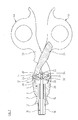
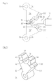
- FIGS. 1 and 2 show a control panel of a medical instrument, which forms the proximal end of the instrument.
- the medical instrument is an endoscopic shaft instrument.
- the control unit has a connection part 2, on which two grip parts 4a and 4b are articulated.
- an opening 6 is formed on the connecting part 2, which extends in the longitudinal direction of the connecting part 2 completely through this.
- Proximal material has the Druchbrechung 6 a section 8, starting from the proximal end of the connecting part 2 in the distal direction continuously rejuvenated.
- a cylindrical section 10 of the opening 6 closes distally to form a shoulder.
- Distal side of the portion 10 tapers through the opening 6 conical and merges into a section 12.
- a sleeve 14 is arranged in the sections 10 and 12, with a distal end section 16 of the sleeve 14 protruding distally from the connection part 2.
- the end portion 16 serves for attachment of a stem tube, not shown in the drawing, of the endoscopic shaft instrument.
- an actuator 18 is guided in the form of a train-pressure rod.
- the actuating element 18 is axially displaceable in the shaft tube and in the connecting part 2. Not visible from the drawing, the actuating element 18 extends through the entire shaft tube and is coupled in the region of the distal end of the instrument with a movably arranged there tool.
- the actuating element 18 has a section 20 with a cross-section that is narrower than the rest of the actuating element 18.
- the proximal end of the actuating element 18 forms a spherical extension 22, which adjoins the portion 20 of the actuating element 18.
- two hinge pins 24 are arranged at a distance from each other in the immediate vicinity of the proximal end of the connection part 2. At these two hinge pins 24, the handle parts 4a and 4b are pivotally hinged to the connector part 2.
- the grip parts 4a and 4b are each formed as a two-part lever. They each have a manually engageable lever arm 26 and a lever arm 28.
- the lever arms 28 of the handle parts 4a and 4b are each in Aligned substantially in the direction of the hinge pin 24, on which the respective other grip part 4a and 4b is articulated. In this respect, the lever arms 28 of the two handle parts 4a and 4b between the hinge pins 24 are aligned with each other.
- the lever arms 28 of the two grip parts 4a and 4b are directly coupled with each other in a movement-related manner.
- the lever arms 28 each have a toothing on the mutually facing sides, wherein the two toothings are engaged with one another.
- the teeth are formed by gear segments 30 which are integrated in recesses 32 of the lever arms 28.
- Fig. 2 has been omitted for reasons of clarity on the presentation of the gears. These are but from the Fig. 3 - 9 clear.
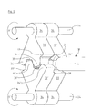
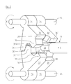
- the gear segments 30 have substantially the shape of a circular sector with an arcuate outer side on which the toothing is formed and two outgoing from the arcuate outer side tapered straight outer sides, at the ends of a bearing eye 34 is formed, which serves to receive a hinge pin 24 ,
- the tapered outer sides of the gear segments 30 enclose an angle of 65 °.
- the toothing of the gear segments 30 is asymmetrical and is formed by two teeth 36 and two tooth gaps 38.
- two gear segments 30 are arranged one above the other, wherein a first gear segment 30 is arranged to a second gear segment 30 'rotated by 180 °, so that there, where there is a tooth gap 38 of the first gear segment 30, a Tooth 36 'of the second gear segment 30' is arranged and where there is a tooth 36 of the first gear segment 30, a tooth gap 38 'of the second gear segment 30' is arranged, which in particular from FIGS. 6 to 8 becomes clear.
- the respectively arranged in the lever arms 28 gear segments 30 and 3ß0 ' are all of identical design, so identical
- the lever arms 28 are coupled via the gear segments 30 and 30 'also directly to the actuating element 18.
- the actuator 18 between the oppositely arranged and mutually engaged gear segments 30 and 30 'out.
- recesses 40 are formed on the gear segments 30 and 30 'on their teeth 36 and 36', starting from a flat side of the gear segments 30 and 30 'and extending substantially over the entire tooth height of the teeth 36 and 36' ( Fig. 9 ).
- a further recess 42 is formed on each of the gear segments 30 and 30 'whose inner contour corresponds to the outer contour of the spherical extension 22 of the actuating element 18.
- the recesses 42 of the superimposed gear segments 30 and 30 'of the gear segment pairs of the lever 28 has a substantially spherical receiving space in which the spherical extension 22 of the actuating element 18 is arranged in a form-fitting manner.
- Fig. 6 to 8 The mode of operation of the medical instrument according to the invention is made in particular from Fig. 6 to 8 clear.
Abstract
Description
Die Erfindung betrifft ein medizinisches Instrument.The invention relates to a medical instrument.
Aus
Die Bewegungskopplung des Betätigungselements mit den Griffteilen erfolgt bei diesen Instrumenten dadurch, dass ein proximaler Endabschnitt des Betätigungselements als Zahnstange mit Verzahnungen an zwei voneinander abgewandten Längsseiten ausgebildet ist, wobei an jeder dieser Verzahnungen ein an den beiden Griffteilen zahnradförmig ausgebildeter Bereich im Eingriff ist. Durch den gleichzeitigen Eingriff der zahnradförmigen Bereiche der Griffteile in die auf Seiten des Betätigungselements ausgebildeten Verzahnungen sind die Schwenkbewegungen der beiden Griffteile synchronisiert. Bei den bekannten Instrumenten erweist es sich als nachteilig, dass deren Herstellung vergleichsweise aufwändig ist. Ein weiterer Nachteil dieser Instrumente besteht darin, dass es für eine Entnahme des Betätigungselements aus dem Instrument, beispielsweise zu Wartungszwecken, erforderlich ist, zuvor die Griffteile zu demontieren.The motion coupling of the actuating element with the handle parts takes place in these instruments in that a proximal end portion of the actuating element is designed as a rack with teeth on two longitudinal sides facing away from each other, wherein at each of these teeth a toothed wheel-shaped at the two handle portions formed in engagement. By the simultaneous engagement of the gear-shaped areas of the handle parts in the formed on sides of the actuator teeth, the pivotal movements of the two handle parts are synchronized. In the known instruments, it proves to be disadvantageous that their production is relatively complex. Another disadvantage of these instruments is that it is necessary for a removal of the actuator from the instrument, for example, for maintenance purposes, previously dismantle the handle parts.
Vor diesem Hintergrund liegt der Erfindung die Aufgabe zugrunde, ein medizinisches Instrument der oben genannten Art zu schaffen, das gegenüber den bislang bekannten Instrumenten einen einfacheren Aufbau aufweist, und dessen Betätigungselement in einfacherer Weise demontiert und montiert werden kann.Against this background, the invention has for its object to provide a medical instrument of the type mentioned above, which has a simpler structure compared to the previously known instruments, and the actuator can be dismantled and mounted in a simpler manner.
Gelöst wird diese Aufgabe durch ein medizinisches Instrument mit den in Anspruch 1 angegebenen Merkmalen. Vorteilhafte Weiterbildungen dieses Instruments ergeben sich aus den Unteransprüchen, der nachfolgenden Beschreibung sowie der Zeichnung. Hierbei können gemäß der Erfindung die in den Unteransprüchen angegebenen Merkmale jeweils für sich, aber auch in geeigneter Kombination die erfindungsgemäße Lösung gemäß Anspruch 1 weiter ausgestalten.This object is achieved by a medical instrument having the features specified in claim 1. Advantageous developments of this instrument will become apparent from the dependent claims, the following description and the drawings. In this case, according to the invention, the features specified in the dependent claims in each case, but also in a suitable combination, the inventive solution according to claim 1 further.
Bei dem erfindungsgemäßen medizinischen Instrument handelt es sich bevorzugt um ein endoskopisches Schaftinstrument, beispielsweise um eine endoskopische Fasszange, Koagulationszange oder Schere. Das Instrument weist ein in einem Schaft axial verschiebbares Betätigungselement auf. Dieses vorzugsweise stangenförmige Betätigungselement kann distalseitig mit einem an dem distalen Ende des Instruments angeordneten Werkzeug und besonders vorteilhaft mit einer dort schwenkbeweglich angeordneten Zangen- oder Scherenbranche bewegungsgekoppelt sein, die zusammen mit einer an dem distalen Ende des Instruments feststehend bzw. starr angeordneten Zangen- oder Scherenbranche ein Zangen- bzw. Scherenmaul bildet.The medical instrument according to the invention is preferably an endoscopic shaft instrument, for example an endoscopic grasping forceps, coagulation forceps or scissors. The instrument has an axially displaceable in a shaft actuator. This preferably rod-shaped actuating element can be coupled in the distal direction with a tool arranged on the distal end of the instrument and particularly advantageously with a pliers or scissors branch arranged pivotably there, which together with a clamp or scissors branch fixed or rigidly arranged at the distal end of the instrument forms a pliers or scissors mouth.
Proximalseitig des Schaftes weist das erfindungsgemäße Instrument zwei beabstandet voneinander schwenkbar angelenkte Hebelarme auf. Jeder dieser Hebelarme ist Teil eines Griffteils zum Betätigen des Instruments. Gemäß der Erfindung sind die Hebelarme mit dem Betätigungselement und unmittelbar miteinander bewegungsgekoppelt. Das heißt, anders als bislang üblich sind die Griffteile nicht indirekt über das Betätigungselement miteinander bewegungsgekoppelt sondern direkt miteinander bewegungsgekoppelt, so dass die zur Synchronisierung der Schwenkbewegungen der Griffteile notwendige Bewegungskopplung der beiden Hebelarme dieser Griffteile miteinander unabhängig von der Bewegungskopplung der Hebelarme mit dem Betätigungselement erfolgt. Dies ermöglicht es, die Bewegungskopplung der Hebelarme mit dem Betätigungselement konstruktiv einfacher auszugestalten und erlaubt ferner einen fertigungstechnisch einfacheren Aufbau des Betätigungselements, an dem proximalseitig beispielsweise nur ein einfacher Mitnehmer ausgebildet sein kann, der in solcher Wirkverbindung mit den Hebelarmen stehen kann, dass eine Schwenkbewegung der direkt miteinander bewegungsgekoppelten Hebelarme eine Linearbewegung des Betätigungselements hervorruft. Weiter vorteilhaft schafft die von der Bewegungskopplung der beiden Hebelarme miteinander getrennte Bewegungskopplung der Hebelarme mit dem Betätigungselement die Möglichkeit, durch eine entsprechende Schwenkbewegung der Hebelarme, die außerhalb des zum Betätigen des Instruments erforderlichen Schwenkbereichs der Hebelarme liegt, die Bewegungskopplung der Hebelarme mit dem Betätigungselement zu lösen, während die unmittelbare Bewegungskopplung der Hebelarme miteinander bestehen bleibt. Auf diese Weise kann das Betätigungselement, falls erforderlich, in einfacher Weise von dem erfindungsgemäßen Instrument demontiert und anschließend wieder montiert werden.Proximalseitig of the shaft, the instrument according to the invention has two spaced apart pivotally hinged lever arms. Each of these lever arms is part of a handle for operating the instrument. According to the invention, the lever arms are coupled to the actuating element and directly coupled to each other. That is, unlike heretofore usual, the handle parts are not indirectly via the actuator motion coupled with each other but coupled directly to each other, so that the necessary for synchronizing the pivoting movements of the handle parts movement coupling of the two lever arms of these handle parts takes place independently of each other of the movement coupling of the lever arms with the actuator. This makes it possible to structurally simpler design the movement coupling of the lever arms with the actuating element and further allows a production engineering simpler structure of the actuating element, on the proximal side, for example, only a simple driver can be formed, which can be in operative connection with the lever arms, that a pivoting movement of the directly with each other motion-coupled lever arms causes a linear movement of the actuating element. Further advantageous provides the mutually separate from the movement coupling of the two lever arms motion coupling of the lever arms with the actuator, the possibility to solve by a corresponding pivoting movement of the lever arms, which is outside the required for operating the instrument pivoting range of the lever arms, the movement coupling of the lever arms with the actuating element while the immediate movement coupling of the lever arms remains together. In this way, the actuator, if necessary, easily disassembled from the instrument according to the invention and then re-assembled.
Zur Schaffung der unmittelbaren Bewegungskopplung der beiden Hebelarme miteinander sind bevorzugt an einander zugewandten Seiten der Hebelarme aufeinander abrollende Wälzflächen ausgebildet. Bei dieser Ausgestaltung sind die einander kontaktierenden Wälzflächen an den Hebelarmen an einer der Schwenkachse des jeweils anderen Hebelarms zugewandten Außenseite angeordnet. Vorteilhaft sind die Wälzflächen kreisbogenförmig ausgebildet, wobei eine Mittelachse der Wälzflächen mit der Schwenkachse des jeweiligen Hebelarms übereinstimmt. Weiter vorteilhaft weisen die beiden kreisförmigen Wälzflächen einen gleich großen Radius auf, so dass keine Unter- bzw. Übersetzungbei der Bewegungskopplung der beiden Hebelarme stattfindet.To create the direct coupling of movement of the two lever arms with each other, rolling surfaces rolling against one another are preferably formed on mutually facing sides of the lever arms. In this embodiment, the contacting rolling surfaces are arranged on the lever arms on one of the pivot axis of the respective other lever arm facing outside. Advantageously, the rolling surfaces are formed in a circular arc, wherein a central axis of the rolling surfaces coincides with the pivot axis of the respective lever arm. Further advantageously, the two circular rolling surfaces on an equal radius, so that no under or Übersetzungsbei takes place in the movement coupling of the two lever arms.
Grundsätzlich ist es möglich, dass die aufeinander abrollenden Wälzflächen der beiden Hebelarme eine Reibpaarung bilden, so dass die Bewegungskopplung der beiden Hebelarme miteinander kraftschlüssig erfolgt. Bevorzugt ist allerdings eine Ausgestaltung, bei der die Bewegungskopplung der beiden Hebelarme formschlüssig erfolgt. In diesem Zusammenhang ist vorteilhaft vorgesehen, dass die Wälzflächen der beiden Hebelarme verzahnt ausgebildet sind, wobei die an den beiden Wälzflächen ausgebildeten Verzahnungen miteinander in Eingriff sind.In principle, it is possible for the rolling surfaces of the two lever arms rolling on one another to form a friction pair, so that the movement coupling of the two lever arms takes place in a non-positive manner. However, a configuration in which the movement coupling of the two lever arms takes place in a form-fitting manner is preferred. In this context, it is advantageously provided that the rolling surfaces of the two lever arms are formed toothed, wherein the teeth formed on the two rolling surfaces are engaged with each other.
Gemäß einer weiteren vorteilhaften Weiterbildung des erfindungsgemäßen Instruments ist das Betätigungselement vorzugsweise zwischen den Wälzflächen geführt. Die Führung des Betätigungselements ist hierbei derart, dass sich die Wälzflächen zumindest in einem Teilbereich immer kontaktieren und so eine unmittelbare Bewegungskopplung der beiden Hebelarme miteinander schaffen.According to a further advantageous development of the instrument according to the invention, the actuating element is preferably guided between the rolling surfaces. The leadership of the actuating element is in this case such that the rolling surfaces always contact at least in a partial area and thus create a direct movement coupling of the two lever arms together.
Zur Führung des Betätigungselements zwischen den Wälzflächen ist an den beiden Wälzflächen vorteilhaft jeweils außenseitig eine Nut ausgebildet. Die Nuten erstrecken sich jeweils als Kreisbogen über die Wälzflächen und sind vorzugsweise in der Schwenkebene der beiden Hebelarme oder in einer dazu parallelen Ebene angeordnet. Zusammen bilden die Nuten einen Aufnahmeraum für das Betätigungselement bzw. einen in Richtung quer zur Längsausdehnung des Betätigungselements geschlossenen Führungskanal.To guide the actuating element between the rolling surfaces, a groove is advantageously formed on the two rolling surfaces in each case on the outside. The grooves extend in each case as a circular arc over the rolling surfaces and are preferably arranged in the pivoting plane of the two lever arms or in a plane parallel thereto. Together, the grooves form a receiving space for the actuating element or a guide channel closed in the direction transverse to the longitudinal extent of the actuating element.
Bevorzugt ist auch das Betätigungselement mit den beiden Hebelarmen über eine formschlüssige Verbindung bewegungsgekoppelt. Zu diesem Zweck kann an dem Betätigungselement vorteilhaft eine Erweiterung, vorzugsweise eine kugelförmige Erweiterung, ausgebildet sein, die in zwei an den Wälzflächen ausgebildete Ausnehmungen eingreift. Bei der an dem Betätigungselement ausgebildeten Erweiterung handelt es sich um einen vorzugsweise am proximalen Ende des Betätigungselements angeordneten Bereich, der gegenüber einem distalseitig daran anschließenden Abschnitt des Betätigungselements einen erweiterten Querschnitt aufweist. Die an den Wälzflächen der beiden Hebelarme vorgesehenen Ausnehmungen sind jeweils im Bereich der an den Wälzflächen ausgebildeten Nuten angeordnet, wobei eine in Längsrichtung der Wälzfläche verlaufende Mittelachse der Ausnehmung jeweils mit einer Mittelachse der Nut übereinstimmt. Wenn die beiden Wälzflächen durch ein gleichzeitiges Verschwenken der Hebelarme aufeinander abrollen, verändert sich die Position der an den Wälzflächen ausgebildeten Ausnehmungen, wodurch die in die beiden Ausnehmungen eingreifende Erweiterung und damit einhergehend das gesamte Betätigungselement in einem gewissen Bereich linear bewegt wird.Preferably, the actuating element with the two lever arms is also coupled for movement via a positive connection. For this purpose, an extension, preferably a spherical extension, be formed, which engages in two recesses formed on the rolling surfaces. The extension formed on the actuating element is a region which is preferably arranged at the proximal end of the actuating element and which has an expanded cross section in relation to a section of the actuating element which adjoins it distally. The recesses provided on the rolling surfaces of the two lever arms are each arranged in the region of the grooves formed on the rolling surfaces, a central axis of the recess extending in the longitudinal direction of the rolling surface in each case coinciding with a central axis of the groove. If the two rolling surfaces by a simultaneous pivoting of the lever arms roll on each other, the position of the recesses formed on the rolling surfaces, whereby the engaging in the two recesses extension and, consequently, the entire actuator is linearly moved in a certain range.
Bevorzugt sind die Wälzflächen in Richtung der Schwenkachsen der Hebelarme zweigeteilt ausgebildet, wobei eine an einem ersten Teil ausgebildete Verzahnung gegenüber einer an einem zweiten Teil ausgebildeten Verzahnung um eine Zahnlückenweite oder Zahndicke versetzt ausgebildet ist. Hierbei erfolgt die Zweiteilung der Wälzflächen zweckmäßigerweise in Richtung der Schwenkachse der Hebelarme. An den Umfangsabschnitten der Wälzflächen, an denen an dem ersten Teil der Wälzflächen Zähne ausgebildet sind, befinden sich an dem zweiten Teil der Wälzflächen Zahnlücken und an den Umfangsabschnitten der Wälzflächen, an denen an dem ersten Teil der Wälzflächen Zahnlücken ausgebildet sind, befinden sich an dem zweiten Teil der Wälzflächen Zähne. Hierbei weisen die an dem ersten Teil der Wälzflächen ausgebildete Verzahnung und die an dem zweiten Teil der Wälzflächen ausgebildete Verzahnung zweckmäßigerweise ein gleiches Zahn- und Zahnlückenprofil auf.Preferably, the rolling surfaces are formed in two parts in the direction of the pivot axes of the lever arms, wherein a toothing formed on a first part is offset from a toothing formed on a second part by a tooth gap width or tooth thickness. In this case, the division of the rolling surfaces expediently takes place in the direction of the pivot axis of the lever arms. At the peripheral portions of the rolling surfaces on which teeth are formed on the first part of the rolling surfaces, there are tooth gaps on the second part of the rolling surfaces and on the peripheral portions of the rolling surfaces where tooth spaces are formed on the first part of the rolling surfaces second part of the rolling surfaces teeth. Here, the teeth formed on the first part of the rolling surfaces and those on the second part of the rolling surfaces trained teeth expediently a same tooth and tooth space profile.
Die in den beiden Teilen der Wälzflächen zueinander versetzten Verzahnungen haben den Vorteil, dass zur Bildung der beiden Verzahnungen der Wälzfläche Verzahnungen mit einem vergleichsweise großen Modul verwendet werden können, so dass die Zahnlücken der einzelnen Verzahnungen verhältnismäßig groß sind und so einen großen Teil der Ausnehmungen zur Aufnahme der an dem Betätigungselement ausgebildeten Erweiterung bilden können. Gleichzeitig ermöglicht die versetzte Anordnung der Verzahnungen eine besonders spielfreie Bewegungskopplung der beiden Hebelarme miteinander.The offset in the two parts of the rolling surfaces gear teeth have the advantage that the formation of the two teeth of the rolling surface gears can be used with a comparatively large module, so that the tooth gaps of the individual gears are relatively large and so a large part of the recesses for Recording can form the formed on the actuator extension. At the same time the staggered arrangement of the gears allows a particularly backlash-free motion coupling of the two lever arms together.
Eine Ausgestaltung, bei der die Wälzflächen in einem zweiten Teil der Wälzflächen eine zu einem ersten Teil der Wälzflächen versetzte Verzahnung aufweist, lässt sich besonders einfach herstellen, wenn, wie es weiter bevorzugt vorgesehen ist, jeweils zwei Zahnradsegmente die Wälzfläche eines Hebelarms bilden, wobei alle Zahnradsegmente baugleich ausgebildet sind. D. h. das erfindungsgemäße Instrument weist insgesamt vier baugleiche Zahnradsegmente auf.An embodiment in which the rolling surfaces in a second part of the rolling surfaces has a toothed offset to a first part of the rolling surfaces, can be particularly easily produced if, as is further preferred, each two gear segments form the rolling surface of a lever arm, all Gear segments are constructed identical. Ie. the instrument according to the invention has a total of four identical gear segments.
Zweckmäßigerweise weisen die Zahnradsegmente eine asymmetrische Verzahnung auf. Das heißt, die an einem Zahnradsegment ausgebildete Verzahnung beginnt mit einem Zahn und endet mit einer Zahnlücke. Zur Schaffung von zweigeteilten Wälzflächen, die in einem ersten Teil eine gegenüber dem zweiten Teil versetzt angeordnete Verzahnung aufweisen, sind zwei Zahnradsegmente übereinander anzuordnen, wobei ein zweites Zahnradsegment gegenüber einem ersten Zahnradsegment um 180° um eine in Radiusrichtung des Zahnradsegments verlaufende Achse verdreht ausgerichtet ist.Appropriately, the gear segments have an asymmetric toothing. That is, the teeth formed on a gear segment starts with a tooth and ends with a tooth gap. To create two-part rolling surfaces, which have in a first part offset from the second part arranged toothing, two gear segments are to be arranged one above the other, wherein a second gear segment is rotated relative to a first gear segment by 180 ° about an axis extending in the radius direction of the gear segment axis.
Es hat sich gezeigt, dass zur Verwirklichung der bei dem erfindungsgemäßen medizinischen Instrument erforderlichen axialen Verschiebewege des Betätigungselements Zahnradsegmente ausreichen, die mit zwei Zähnen und zwei Zahnlücken ausgestattet sind, wobei sich die an dem Zahnradsegment ausgebildete Verzahnung über einen Winkelbereich von 65° erstreckt. Insofern ist eine Ausgestaltung der Zahnradsegmente vorgesehen, bei der die Zahnradsegmente vorteilhaft jeweils zwei Zähne und zwei Zahnlücken aufweisen, wobei sie weiter vorteilhaft einen Winkel von 65° einschließen.It has been found that, in order to realize the axial displacement paths of the actuating element required in the medical instrument according to the invention, toothed segments equipped with two teeth and two tooth spaces are sufficient, the toothing formed on the toothed wheel segment extending over an angular range of 65 °. In this respect, an embodiment of the gear segments is provided, in which the gear segments advantageously each have two teeth and two tooth gaps, and further advantageously include an angle of 65 °.
Bevorzugt sind die Zahnradsegmente in den Griffteilen zum Betätigen des erfindungsgemäßen Instruments integriert. So kann an jedem der beiden Griffteile eine Ausnehmung ausgebildet sein, in die jeweils zwei Zahnradsegmente übereinander in der oben beschriebenen Weise angeordnet sind. Des Weiteren können die beiden Zahnradsegmente eines Griffteils auch mit einem das Griffteil bildenden Kunststoff umspritzt sein.Preferably, the gear segments are integrated in the handle parts for actuating the instrument according to the invention. Thus, a recess may be formed on each of the two grip parts, in each of which two gear segments are arranged one above the other in the manner described above. Furthermore, the two gear segments of a grip part can also be encapsulated with a plastic forming the grip part.
Nachfolgend ist die Erfindung anhand eines in der Zeichnung dargestellten Ausführungsbeispiels näher erläutert. In der Zeichnung zeigt:
- Fig. 1
- in einer schematisch vereinfachten perspektivischen Ansicht ein Bedienteil eines medizinischen Instruments,
- Fig. 2
- das Bedienteil nach
Fig. 1 in einer teilgeschnittenen Seitenansicht, - Fig. 3
- in einer Prinzipdarstellung, die Eingriffsverhältnisse von zwei Zahnradsegmenten und einem Betätigungselement in dem Bedienteil nach
Fig. 1 in einer ersten Eingriffsstellung, - Fig. 4
- in einer Prinzipdarstellung, die Eingriffsverhältnisse von zwei Zahnradsegmenten und einem Betätigungselement in dem Bedienteil nach
Fig. 1 in einer zweiten Eingriffsstellung, - Fig. 5
- in einer Prinzipdarstellung, die Eingriffsverhältnisse von zwei Zahnradsegmenten und einem Betätigungselement in dem Bedienteil nach
Fig. 1 in einer dritten Eingriffsstellung, - Fig. 6
- die Eingriffsverhältnisse nach
Fig. 3 in einer perspektivischen Darstellung, - Fig. 7
- die Eingriffsverhältnisse nach
Fig. 4 in einer perspektivischen Darstellung, - Fig. 8
- die Eingriffsverhältnisse nach
Fig. 5 in einer perspektivischen Darstellung und - Fig. 9
- ein Zahnradsegment in einer perspektivischen Einzeldarstellung.
- Fig. 1
- in a schematically simplified perspective view of a control panel of a medical instrument,
- Fig. 2
- the control panel after
Fig. 1 in a partially sectioned side view, - Fig. 3
- in a schematic diagram, the engagement conditions of two gear segments and an actuating element in the control panel according to
Fig. 1 in a first engaged position, - Fig. 4
- in a schematic diagram, the engagement conditions of two gear segments and an actuating element in the control panel according to
Fig. 1 in a second engaged position, - Fig. 5
- in a schematic diagram, the engagement conditions of two gear segments and an actuating element in the control panel according to
Fig. 1 in a third engaged position, - Fig. 6
- the engagement conditions after
Fig. 3 in a perspective view, - Fig. 7
- the engagement conditions after
Fig. 4 in a perspective view, - Fig. 8
- the engagement conditions after
Fig. 5 in a perspective view and - Fig. 9
- a gear segment in a perspective detail view.
Die
Wie der
In der Durchbrechung 6 des Anschlussteils 2 ist in den Abschnitten 10 und 12 eine Hülse 14 angeordnet, wobei ein distaler Endabschnitt 16 der Hülse 14 distalseitig aus dem Anschlussteil 2 herausragt. Der Endabschnitt 16 dient zur Befestigung eines in der Zeichnung nicht dargestellten Schaftsrohrs des endoskopischen Schaftinstruments.In the opening 6 of the connection part 2, a
Durch dieses Schaftrohr sowie durch das Innenlumen der Hülse 14 ist ein Betätigungselement 18 in Form einer Zug-Druck-Stange geführt. Das Betätigungselement 18 ist in dem Schaftrohr sowie in dem Anschlussteil 2 axial verschiebbar. Aus der Zeichnung nicht ersichtlich erstreckt sich das Betätigungselement 18 durch das gesamte Schaftrohr und ist im Bereich des distalen Endes des Instruments mit einem dort beweglich angeordneten Werkzeug bewegungsgekoppelt.Through this shaft tube and through the inner lumen of the
An seinem proximalen Ende weist das Betätigungselement 18 einen Abschnitt 20 mit einem gegenüber dem übrigen Betätigungselement 18 verjüngten Querschnitt auf. Das proximale Ende des Betätigungselements 18 bildet eine kugelförmige Erweiterung 22, die sich an den Abschnitt 20 des Betätigungselements 18 anschließt. In dem Abschnitt 8 des Anschlussteils 2 sind in unmittelbarer Nähe zu dem proximalen Ende des Anschlussteils 2 zwei Gelenkstifte 24 beabstandet voneinander angeordnet. An diesen beiden Gelenkstiften 24 sind die Griffteile 4a und 4b schwenkbeweglich an dem Anschlussteil 2 angelenkt.At its proximal end, the
Die Griffteile 4a und 4b sind jeweils als zweiteilige Hebel ausgebildet. Sie weisen jeweils eine manuell zu greifenden Hebelarm 26 und einen Hebelarm 28 auf. Die Hebelarme 28 der Griffteile 4a und 4b sind jeweils im Wesentlichen in Richtung auf den Gelenkstift 24 ausgerichtet, an dem das jeweils andere Griffteil 4a bzw. 4b angelenkt ist. Insofern sind die Hebelarme 28 der beiden Griffteile 4a und 4b zwischen den Gelenkstiften 24 aufeinander zu ausgerichtet.The
Die Hebelarme 28 der beiden Griffteile 4a und 4b sind unmittelbar miteinander bewegungsgekoppelt. Zu diesem Zweck weisen die Hebelarme 28 an den einander zugewandten Seiten jeweils eine Verzahnung auf, wobei die beiden Verzahnungen miteinander in Eingriff sind. Die Verzahnungen werden von Zahnradsegmenten 30 gebildet, die in Ausnehmungen 32 der Hebelarme 28 integriert sind. In
Die Zahnradsegmente 30 haben im Wesentlichen die Form eines Kreissektors mit einer kreisbogenförmigen Außenseite, an der die Verzahnung ausgebildet ist und zwei von der kreisbogenförmigen Außenseite ausgehende spitz zueinander zulaufende gerade Außenseiten, an deren Enden ein Lagerauge 34 ausgebildet ist, das zur Aufnahme eines Gelenkstifts 24 dient. Die spitz aufeinander zulaufenden Außenseiten der Zahnradsegmente 30 schließen einen Winkel von 65° ein. Die Verzahnung der Zahnradsegmente 30 ist asymmetrisch und wird von zwei Zähnen 36 und zwei Zahnlücken 38 gebildet.The
In den Ausnehmungen 32 der beiden Hebelarme 28 sind jeweils zwei Zahnradsegmente 30 übereinander angeordnet, wobei ein erstes Zahnradsegment 30 zu einem zweiten Zahnradsegment 30' um 180° gedreht angeordnet ist, sodass sich dort, wo sich eine Zahnlücke 38 des ersten Zahnradsegments 30 befindet, ein Zahn 36' des zweiten Zahnradsegments 30' angeordnet ist und dort, wo sich ein Zahn 36 des ersten Zahnradsegments 30 befindet, eine Zahnlücke 38' des zweiten Zahnradsegments 30' angeordnet ist, was insbesondere aus den
Die Hebelarme 28 sind über deren Zahnradsegmente 30 und 30' auch direkt mit dem Betätigungselement 18 bewegungsgekoppelt. Hierbei ist das Betätigungselement 18 zwischen den einander gegenüberliegend angeordneten und miteinander in Eingriff befindlichen Zahnradsegmenten 30 und 30' geführt. Zu diesem Zweck sind an den Zahnradsegmenten 30 und 30' an deren Zähnen 36 und 36' ausgehend von einer Flachseite der Zahnradsegmente 30 und 30' Ausnehmungen 40 ausgebildet, die sich im Wesentlichen über die gesamte Zahnhöhe der Zähne 36 und 36' erstrecken (
Zur Aufnahme der an dem proximalen Ende des Betätigungselements 18 ausgebildeten kugelförmigen Erweiterung 22 ist an jedem der Zahnradsegmente 30 und 30' eine weitere Ausnehmungen 42 ausgebildet, deren Innenkontur mit der Außenkontur der kugelförmigen Erweiterung 22 des Betätigungselements 18 korrespondiert. Zusammen bilden die Ausnehmungen 42 der übereinander angeordneten Zahnradsegmente 30 und 30' der Zahnradsegmentpaare der Hebel 28 einen im Wesentlichen kugelförmigen Aufnahmeraum, in dem die kugelförmige Erweiterung 22 des Betätigungselements 18 formschlüssig angeordnet ist.For receiving the
Die Funktionsweise des erfindungsgemäßen medizinischen Instruments wird insbesondere aus den
- 22
- Anschlussteilconnector
- 4a, 4b4a, 4b
- Griffteilhandle part
- 66
- Durchbrechungperforation
- 88th
- Abschnittsection
- 1010
- Abschnittsection
- 1212
- Abschnittsection
- 1414
- Hülseshell
- 1616
- Endabschnittend
- 1818
- Betätigungselementactuator
- 2020
- Abschnittsection
- 2222
- Erweiterungextension
- 2424
- Gelenkstiftpintle
- 1616
- Hebelarmlever arm
- 2828
- Hebelarmlever arm
- 30, 30'30, 30 '
- Zahnradsegmentgear segment
- 3232
- Ausnehmungrecess
- 3434
- Lageraugebearing eye
- 36, 36'36, 36 '
- Zahntooth
- 38, 38'38, 38 '
- Zahnlückegap
- 4040
- Ausnehmungrecess
- 4242
- Ausnehmungrecess
- AA
- Richtungdirection
- BB
- Richtungdirection
- CC
- Richtungdirection
Claims (12)
Applications Claiming Priority (1)
| Application Number | Priority Date | Filing Date | Title |
|---|---|---|---|
| DE102011088003A DE102011088003A1 (en) | 2011-12-08 | 2011-12-08 | Medical instrument |
Publications (2)
| Publication Number | Publication Date |
|---|---|
| EP2601895A1 true EP2601895A1 (en) | 2013-06-12 |
| EP2601895B1 EP2601895B1 (en) | 2015-08-12 |
Family
ID=47278138
Family Applications (1)
| Application Number | Title | Priority Date | Filing Date |
|---|---|---|---|
| EP12193321.2A Active EP2601895B1 (en) | 2011-12-08 | 2012-11-20 | Medical instrument |
Country Status (5)
| Country | Link |
|---|---|
| US (1) | US8926599B2 (en) |
| EP (1) | EP2601895B1 (en) |
| JP (1) | JP6055664B2 (en) |
| CN (1) | CN103156669B (en) |
| DE (1) | DE102011088003A1 (en) |
Cited By (1)
| Publication number | Priority date | Publication date | Assignee | Title |
|---|---|---|---|---|
| EP2996620A4 (en) * | 2013-05-15 | 2017-11-08 | Intuitive Surgical Operations, Inc. | Force transmission mechanism for teleoperated surgical system |
Families Citing this family (2)
| Publication number | Priority date | Publication date | Assignee | Title |
|---|---|---|---|---|
| DE102013211368B4 (en) | 2013-06-18 | 2024-02-22 | Richard Wolf Gmbh | Endoscopic shaft instrument |
| CN110051410B (en) * | 2019-05-15 | 2022-02-22 | 成都五义医疗科技有限公司 | Slender shaft assembly capable of being detached, washed and reused and surgical instrument thereof |
Citations (4)
| Publication number | Priority date | Publication date | Assignee | Title |
|---|---|---|---|---|
| DE665208C (en) | 1936-12-08 | 1938-09-20 | Ernst Axel Johan Ericsson | Plaster cast scissors |
| US5176699A (en) * | 1991-06-05 | 1993-01-05 | Harold Markham | Surgical device with double jaw actuation |
| FR2688681A1 (en) | 1992-03-23 | 1993-09-24 | Lebosse Guy | Universal handle for coeliosurgery instrumentation |
| US6425906B1 (en) * | 1998-01-19 | 2002-07-30 | Michael John Radley Young | Ultrasonic cutting tool |
Family Cites Families (14)
| Publication number | Priority date | Publication date | Assignee | Title |
|---|---|---|---|---|
| CA1134701A (en) | 1977-10-17 | 1982-11-02 | David T. Green | Surgical clip applicator |
| US5282806A (en) * | 1992-08-21 | 1994-02-01 | Habley Medical Technology Corporation | Endoscopic surgical instrument having a removable, rotatable, end effector assembly |
| JP3518603B2 (en) * | 1992-06-24 | 2004-04-12 | マイクロサージ・インコーポレーテツド | Surgical tool assembly and surgical instrument |
| DE19508186C2 (en) * | 1995-03-09 | 1998-01-15 | Stefan Koscher | Surgical instrument |
| US5700270A (en) * | 1995-10-20 | 1997-12-23 | United States Surgical Corporation | Surgical clip applier |
| US20060287642A1 (en) * | 2005-06-16 | 2006-12-21 | Alfred Perlin | Laparoscopic surgical instrument having lockable handles with a latch feature |
| EP1815809B1 (en) * | 2006-02-01 | 2010-09-08 | Arthrex, Inc. | Handle for surgical instruments |
| US9561045B2 (en) * | 2006-06-13 | 2017-02-07 | Intuitive Surgical Operations, Inc. | Tool with rotation lock |
| WO2008008441A2 (en) * | 2006-07-12 | 2008-01-17 | Nelson Drew V | Multifunctional surgical instrument |
| DE102006038515A1 (en) * | 2006-08-17 | 2008-02-21 | Karl Storz Gmbh & Co. Kg | Medical tubular shaft instrument |
| DE202007000427U1 (en) * | 2007-01-08 | 2007-03-08 | Aesculap Ag & Co. Kg | Surgical operating handle for a surgical instrument, especially an endoscopic instrument, comprises a handle part positioned on the operating handle |
| US8728057B2 (en) * | 2009-06-04 | 2014-05-20 | Adapta Medical, Inc. | Devices and methods for catheter advancement |
| EP3437571B1 (en) * | 2009-12-22 | 2020-06-17 | Cook Medical Technologies LLC | Medical devices with detachable pivotable jaws |
| CN102247180B (en) * | 2011-06-30 | 2013-01-02 | 李宝童 | Medical needle-holding forceps |
-
2011
- 2011-12-08 DE DE102011088003A patent/DE102011088003A1/en not_active Withdrawn
-
2012
- 2012-11-20 EP EP12193321.2A patent/EP2601895B1/en active Active
- 2012-12-04 JP JP2012265341A patent/JP6055664B2/en active Active
- 2012-12-05 US US13/705,796 patent/US8926599B2/en active Active
- 2012-12-10 CN CN201210528384.5A patent/CN103156669B/en active Active
Patent Citations (4)
| Publication number | Priority date | Publication date | Assignee | Title |
|---|---|---|---|---|
| DE665208C (en) | 1936-12-08 | 1938-09-20 | Ernst Axel Johan Ericsson | Plaster cast scissors |
| US5176699A (en) * | 1991-06-05 | 1993-01-05 | Harold Markham | Surgical device with double jaw actuation |
| FR2688681A1 (en) | 1992-03-23 | 1993-09-24 | Lebosse Guy | Universal handle for coeliosurgery instrumentation |
| US6425906B1 (en) * | 1998-01-19 | 2002-07-30 | Michael John Radley Young | Ultrasonic cutting tool |
Cited By (1)
| Publication number | Priority date | Publication date | Assignee | Title |
|---|---|---|---|---|
| EP2996620A4 (en) * | 2013-05-15 | 2017-11-08 | Intuitive Surgical Operations, Inc. | Force transmission mechanism for teleoperated surgical system |
Also Published As
| Publication number | Publication date |
|---|---|
| JP2013119036A (en) | 2013-06-17 |
| CN103156669B (en) | 2016-09-07 |
| DE102011088003A1 (en) | 2013-06-13 |
| US8926599B2 (en) | 2015-01-06 |
| US20130150665A1 (en) | 2013-06-13 |
| CN103156669A (en) | 2013-06-19 |
| JP6055664B2 (en) | 2016-12-27 |
| EP2601895B1 (en) | 2015-08-12 |
Similar Documents
| Publication | Publication Date | Title |
|---|---|---|
| EP3175801B1 (en) | Medical instrument | |
| DE102009042491A1 (en) | Surgical instrument for use as shaver, has zone arranged in area of distal section, and drive element rotatably supported in shaft, where flexible section of element exhibits length in axial direction, which corresponds to length of zone | |
| DE102009042150A1 (en) | Surgical instrument to be used in combination with a trocar or something similar has proximal and distal ends as well as an end section with an articulated zone | |
| WO2015081946A1 (en) | Instrument, in particular a medical endoscopic instrument or technoscope | |
| EP2696741B1 (en) | Control apparatus | |
| EP3012924A1 (en) | Jointing clamp | |
| EP3175802B1 (en) | Medical instrument | |
| EP1721577B1 (en) | Endoscopic instrument | |
| WO2014124846A1 (en) | Instrument, in particular medical endoscopic instrument or technoscope | |
| EP2601895B1 (en) | Medical instrument | |
| DE102014219195A1 (en) | Instrument, in particular medico-endoscopic shaft instrument | |
| EP2653122B1 (en) | Tool for a medical instrument | |
| WO2023006541A1 (en) | Bendable shaft for a medical hand-held instrument | |
| EP3695793B1 (en) | Medical instrument | |
| DE102013207248A1 (en) | Instrument, in particular a medical endoscopic instrument or technoscope | |
| DE102014206930B4 (en) | Instrument, in particular medical endoscopic instrument | |
| EP2403418B1 (en) | Medical instrument | |
| DE4444025C2 (en) | Actuator for a medical forceps and its use in a medical forceps | |
| DE202007000427U1 (en) | Surgical operating handle for a surgical instrument, especially an endoscopic instrument, comprises a handle part positioned on the operating handle | |
| DE102013003316B4 (en) | Surgical jaw instrument | |
| EP2898818B1 (en) | Endoscopic instrument | |
| DE102011109721B4 (en) | Surgical instrumet | |
| DE10136963B4 (en) | Surgical instrument | |
| DE19703600A1 (en) | Medical instrument for use in endoscopic examinations | |
| DE102021119526A1 (en) | Surgical instrument and steering gear therefor |
Legal Events
| Date | Code | Title | Description |
|---|---|---|---|
| PUAI | Public reference made under article 153(3) epc to a published international application that has entered the european phase |
Free format text: ORIGINAL CODE: 0009012 |
|
| AK | Designated contracting states |
Kind code of ref document: A1 Designated state(s): AL AT BE BG CH CY CZ DE DK EE ES FI FR GB GR HR HU IE IS IT LI LT LU LV MC MK MT NL NO PL PT RO RS SE SI SK SM TR |
|
| AX | Request for extension of the european patent |
Extension state: BA ME |
|
| 17P | Request for examination filed |
Effective date: 20131128 |
|
| RBV | Designated contracting states (corrected) |
Designated state(s): AL AT BE BG CH CY CZ DE DK EE ES FI FR GB GR HR HU IE IS IT LI LT LU LV MC MK MT NL NO PL PT RO RS SE SI SK SM TR |
|
| GRAP | Despatch of communication of intention to grant a patent |
Free format text: ORIGINAL CODE: EPIDOSNIGR1 |
|
| INTG | Intention to grant announced |
Effective date: 20150316 |
|
| GRAS | Grant fee paid |
Free format text: ORIGINAL CODE: EPIDOSNIGR3 |
|
| GRAA | (expected) grant |
Free format text: ORIGINAL CODE: 0009210 |
|
| AK | Designated contracting states |
Kind code of ref document: B1 Designated state(s): AL AT BE BG CH CY CZ DE DK EE ES FI FR GB GR HR HU IE IS IT LI LT LU LV MC MK MT NL NO PL PT RO RS SE SI SK SM TR |
|
| REG | Reference to a national code |
Ref country code: GB Ref legal event code: FG4D Free format text: NOT ENGLISH |
|
| REG | Reference to a national code |
Ref country code: CH Ref legal event code: EP |
|
| REG | Reference to a national code |
Ref country code: AT Ref legal event code: REF Ref document number: 741402 Country of ref document: AT Kind code of ref document: T Effective date: 20150815 |
|
| REG | Reference to a national code |
Ref country code: IE Ref legal event code: FG4D Free format text: LANGUAGE OF EP DOCUMENT: GERMAN |
|
| REG | Reference to a national code |
Ref country code: DE Ref legal event code: R096 Ref document number: 502012004092 Country of ref document: DE |
|
| REG | Reference to a national code |
Ref country code: FR Ref legal event code: PLFP Year of fee payment: 4 |
|
| REG | Reference to a national code |
Ref country code: CH Ref legal event code: NV Representative=s name: ISLER AND PEDRAZZINI AG, CH |
|
| REG | Reference to a national code |
Ref country code: LT Ref legal event code: MG4D |
|
| REG | Reference to a national code |
Ref country code: NL Ref legal event code: FP |
|
| PG25 | Lapsed in a contracting state [announced via postgrant information from national office to epo] |
Ref country code: LT Free format text: LAPSE BECAUSE OF FAILURE TO SUBMIT A TRANSLATION OF THE DESCRIPTION OR TO PAY THE FEE WITHIN THE PRESCRIBED TIME-LIMIT Effective date: 20150812 Ref country code: FI Free format text: LAPSE BECAUSE OF FAILURE TO SUBMIT A TRANSLATION OF THE DESCRIPTION OR TO PAY THE FEE WITHIN THE PRESCRIBED TIME-LIMIT Effective date: 20150812 Ref country code: GR Free format text: LAPSE BECAUSE OF FAILURE TO SUBMIT A TRANSLATION OF THE DESCRIPTION OR TO PAY THE FEE WITHIN THE PRESCRIBED TIME-LIMIT Effective date: 20151113 Ref country code: NO Free format text: LAPSE BECAUSE OF FAILURE TO SUBMIT A TRANSLATION OF THE DESCRIPTION OR TO PAY THE FEE WITHIN THE PRESCRIBED TIME-LIMIT Effective date: 20151112 Ref country code: LV Free format text: LAPSE BECAUSE OF FAILURE TO SUBMIT A TRANSLATION OF THE DESCRIPTION OR TO PAY THE FEE WITHIN THE PRESCRIBED TIME-LIMIT Effective date: 20150812 |
|
| PG25 | Lapsed in a contracting state [announced via postgrant information from national office to epo] |
Ref country code: IS Free format text: LAPSE BECAUSE OF FAILURE TO SUBMIT A TRANSLATION OF THE DESCRIPTION OR TO PAY THE FEE WITHIN THE PRESCRIBED TIME-LIMIT Effective date: 20151212 Ref country code: HR Free format text: LAPSE BECAUSE OF FAILURE TO SUBMIT A TRANSLATION OF THE DESCRIPTION OR TO PAY THE FEE WITHIN THE PRESCRIBED TIME-LIMIT Effective date: 20150812 Ref country code: PL Free format text: LAPSE BECAUSE OF FAILURE TO SUBMIT A TRANSLATION OF THE DESCRIPTION OR TO PAY THE FEE WITHIN THE PRESCRIBED TIME-LIMIT Effective date: 20150812 Ref country code: PT Free format text: LAPSE BECAUSE OF FAILURE TO SUBMIT A TRANSLATION OF THE DESCRIPTION OR TO PAY THE FEE WITHIN THE PRESCRIBED TIME-LIMIT Effective date: 20151214 Ref country code: ES Free format text: LAPSE BECAUSE OF FAILURE TO SUBMIT A TRANSLATION OF THE DESCRIPTION OR TO PAY THE FEE WITHIN THE PRESCRIBED TIME-LIMIT Effective date: 20150812 Ref country code: RS Free format text: LAPSE BECAUSE OF FAILURE TO SUBMIT A TRANSLATION OF THE DESCRIPTION OR TO PAY THE FEE WITHIN THE PRESCRIBED TIME-LIMIT Effective date: 20150812 Ref country code: SE Free format text: LAPSE BECAUSE OF FAILURE TO SUBMIT A TRANSLATION OF THE DESCRIPTION OR TO PAY THE FEE WITHIN THE PRESCRIBED TIME-LIMIT Effective date: 20150812 |
|
| PG25 | Lapsed in a contracting state [announced via postgrant information from national office to epo] |
Ref country code: IT Free format text: LAPSE BECAUSE OF FAILURE TO SUBMIT A TRANSLATION OF THE DESCRIPTION OR TO PAY THE FEE WITHIN THE PRESCRIBED TIME-LIMIT Effective date: 20150812 Ref country code: EE Free format text: LAPSE BECAUSE OF FAILURE TO SUBMIT A TRANSLATION OF THE DESCRIPTION OR TO PAY THE FEE WITHIN THE PRESCRIBED TIME-LIMIT Effective date: 20150812 Ref country code: SK Free format text: LAPSE BECAUSE OF FAILURE TO SUBMIT A TRANSLATION OF THE DESCRIPTION OR TO PAY THE FEE WITHIN THE PRESCRIBED TIME-LIMIT Effective date: 20150812 Ref country code: DK Free format text: LAPSE BECAUSE OF FAILURE TO SUBMIT A TRANSLATION OF THE DESCRIPTION OR TO PAY THE FEE WITHIN THE PRESCRIBED TIME-LIMIT Effective date: 20150812 |
|
| REG | Reference to a national code |
Ref country code: DE Ref legal event code: R097 Ref document number: 502012004092 Country of ref document: DE |
|
| PG25 | Lapsed in a contracting state [announced via postgrant information from national office to epo] |
Ref country code: RO Free format text: LAPSE BECAUSE OF FAILURE TO SUBMIT A TRANSLATION OF THE DESCRIPTION OR TO PAY THE FEE WITHIN THE PRESCRIBED TIME-LIMIT Effective date: 20150812 |
|
| PLBE | No opposition filed within time limit |
Free format text: ORIGINAL CODE: 0009261 |
|
| STAA | Information on the status of an ep patent application or granted ep patent |
Free format text: STATUS: NO OPPOSITION FILED WITHIN TIME LIMIT |
|
| PG25 | Lapsed in a contracting state [announced via postgrant information from national office to epo] |
Ref country code: MC Free format text: LAPSE BECAUSE OF FAILURE TO SUBMIT A TRANSLATION OF THE DESCRIPTION OR TO PAY THE FEE WITHIN THE PRESCRIBED TIME-LIMIT Effective date: 20150812 |
|
| 26N | No opposition filed |
Effective date: 20160513 |
|
| REG | Reference to a national code |
Ref country code: IE Ref legal event code: MM4A |
|
| PG25 | Lapsed in a contracting state [announced via postgrant information from national office to epo] |
Ref country code: SI Free format text: LAPSE BECAUSE OF FAILURE TO SUBMIT A TRANSLATION OF THE DESCRIPTION OR TO PAY THE FEE WITHIN THE PRESCRIBED TIME-LIMIT Effective date: 20150812 |
|
| REG | Reference to a national code |
Ref country code: FR Ref legal event code: PLFP Year of fee payment: 5 |
|
| PG25 | Lapsed in a contracting state [announced via postgrant information from national office to epo] |
Ref country code: IE Free format text: LAPSE BECAUSE OF NON-PAYMENT OF DUE FEES Effective date: 20151120 |
|
| PG25 | Lapsed in a contracting state [announced via postgrant information from national office to epo] |
Ref country code: BG Free format text: LAPSE BECAUSE OF FAILURE TO SUBMIT A TRANSLATION OF THE DESCRIPTION OR TO PAY THE FEE WITHIN THE PRESCRIBED TIME-LIMIT Effective date: 20150812 Ref country code: HU Free format text: LAPSE BECAUSE OF FAILURE TO SUBMIT A TRANSLATION OF THE DESCRIPTION OR TO PAY THE FEE WITHIN THE PRESCRIBED TIME-LIMIT; INVALID AB INITIO Effective date: 20121120 Ref country code: SM Free format text: LAPSE BECAUSE OF FAILURE TO SUBMIT A TRANSLATION OF THE DESCRIPTION OR TO PAY THE FEE WITHIN THE PRESCRIBED TIME-LIMIT Effective date: 20150812 |
|
| PG25 | Lapsed in a contracting state [announced via postgrant information from national office to epo] |
Ref country code: CY Free format text: LAPSE BECAUSE OF FAILURE TO SUBMIT A TRANSLATION OF THE DESCRIPTION OR TO PAY THE FEE WITHIN THE PRESCRIBED TIME-LIMIT Effective date: 20150812 |
|
| PG25 | Lapsed in a contracting state [announced via postgrant information from national office to epo] |
Ref country code: MT Free format text: LAPSE BECAUSE OF FAILURE TO SUBMIT A TRANSLATION OF THE DESCRIPTION OR TO PAY THE FEE WITHIN THE PRESCRIBED TIME-LIMIT Effective date: 20150812 |
|
| REG | Reference to a national code |
Ref country code: FR Ref legal event code: PLFP Year of fee payment: 6 |
|
| PG25 | Lapsed in a contracting state [announced via postgrant information from national office to epo] |
Ref country code: MK Free format text: LAPSE BECAUSE OF FAILURE TO SUBMIT A TRANSLATION OF THE DESCRIPTION OR TO PAY THE FEE WITHIN THE PRESCRIBED TIME-LIMIT Effective date: 20150812 Ref country code: TR Free format text: LAPSE BECAUSE OF FAILURE TO SUBMIT A TRANSLATION OF THE DESCRIPTION OR TO PAY THE FEE WITHIN THE PRESCRIBED TIME-LIMIT Effective date: 20150812 |
|
| PG25 | Lapsed in a contracting state [announced via postgrant information from national office to epo] |
Ref country code: AL Free format text: LAPSE BECAUSE OF FAILURE TO SUBMIT A TRANSLATION OF THE DESCRIPTION OR TO PAY THE FEE WITHIN THE PRESCRIBED TIME-LIMIT Effective date: 20150812 |
|
| PGFP | Annual fee paid to national office [announced via postgrant information from national office to epo] |
Ref country code: BE Payment date: 20221118 Year of fee payment: 11 |
|
| PGFP | Annual fee paid to national office [announced via postgrant information from national office to epo] |
Ref country code: NL Payment date: 20231122 Year of fee payment: 12 Ref country code: LU Payment date: 20231120 Year of fee payment: 12 |
|
| PGFP | Annual fee paid to national office [announced via postgrant information from national office to epo] |
Ref country code: GB Payment date: 20231123 Year of fee payment: 12 |
|
| PGFP | Annual fee paid to national office [announced via postgrant information from national office to epo] |
Ref country code: FR Payment date: 20231122 Year of fee payment: 12 Ref country code: DE Payment date: 20231122 Year of fee payment: 12 Ref country code: CZ Payment date: 20231108 Year of fee payment: 12 Ref country code: CH Payment date: 20231201 Year of fee payment: 12 Ref country code: AT Payment date: 20231117 Year of fee payment: 12 |
|
| PGFP | Annual fee paid to national office [announced via postgrant information from national office to epo] |
Ref country code: BE Payment date: 20231121 Year of fee payment: 12 |