EP2574948A2 - Electric storage device monitor - Google Patents
Electric storage device monitor Download PDFInfo
- Publication number
- EP2574948A2 EP2574948A2 EP12006310A EP12006310A EP2574948A2 EP 2574948 A2 EP2574948 A2 EP 2574948A2 EP 12006310 A EP12006310 A EP 12006310A EP 12006310 A EP12006310 A EP 12006310A EP 2574948 A2 EP2574948 A2 EP 2574948A2
- Authority
- EP
- European Patent Office
- Prior art keywords
- detected value
- monitor
- detected
- value
- voltage
- Prior art date
- Legal status (The legal status is an assumption and is not a legal conclusion. Google has not performed a legal analysis and makes no representation as to the accuracy of the status listed.)
- Granted
Links
- 238000005259 measurement Methods 0.000 claims abstract description 29
- 238000012544 monitoring process Methods 0.000 claims description 24
- XEEYBQQBJWHFJM-UHFFFAOYSA-N Iron Chemical compound [Fe] XEEYBQQBJWHFJM-UHFFFAOYSA-N 0.000 claims description 20
- HBBGRARXTFLTSG-UHFFFAOYSA-N Lithium ion Chemical compound [Li+] HBBGRARXTFLTSG-UHFFFAOYSA-N 0.000 claims description 11
- 229910001416 lithium ion Inorganic materials 0.000 claims description 11
- 229910052742 iron Inorganic materials 0.000 claims description 10
- 230000015654 memory Effects 0.000 claims description 9
- 230000004044 response Effects 0.000 claims description 4
- 229910000398 iron phosphate Inorganic materials 0.000 claims description 3
- WBJZTOZJJYAKHQ-UHFFFAOYSA-K iron(3+) phosphate Chemical compound [Fe+3].[O-]P([O-])([O-])=O WBJZTOZJJYAKHQ-UHFFFAOYSA-K 0.000 claims description 3
- 230000002159 abnormal effect Effects 0.000 abstract description 5
- 238000000034 method Methods 0.000 description 9
- 238000004891 communication Methods 0.000 description 7
- 238000012545 processing Methods 0.000 description 7
- 238000005516 engineering process Methods 0.000 description 5
- 239000003990 capacitor Substances 0.000 description 2
- 230000003247 decreasing effect Effects 0.000 description 2
- 238000001514 detection method Methods 0.000 description 2
- 238000007599 discharging Methods 0.000 description 2
- OKTJSMMVPCPJKN-UHFFFAOYSA-N Carbon Chemical compound [C] OKTJSMMVPCPJKN-UHFFFAOYSA-N 0.000 description 1
- 229910052493 LiFePO4 Inorganic materials 0.000 description 1
- 230000005856 abnormality Effects 0.000 description 1
- 229910052799 carbon Inorganic materials 0.000 description 1
- 238000010586 diagram Methods 0.000 description 1
- 230000000694 effects Effects 0.000 description 1
- 230000005611 electricity Effects 0.000 description 1
- GELKBWJHTRAYNV-UHFFFAOYSA-K lithium iron phosphate Chemical compound [Li+].[Fe+2].[O-]P([O-])([O-])=O GELKBWJHTRAYNV-UHFFFAOYSA-K 0.000 description 1
- 239000010450 olivine Substances 0.000 description 1
- 229910052609 olivine Inorganic materials 0.000 description 1
- -1 that is Chemical compound 0.000 description 1
- 230000003936 working memory Effects 0.000 description 1
Images


Classifications
-
- G—PHYSICS
- G06—COMPUTING; CALCULATING OR COUNTING
- G06F—ELECTRIC DIGITAL DATA PROCESSING
- G06F1/00—Details not covered by groups G06F3/00 - G06F13/00 and G06F21/00
- G06F1/26—Power supply means, e.g. regulation thereof
- G06F1/32—Means for saving power
- G06F1/3203—Power management, i.e. event-based initiation of a power-saving mode
- G06F1/3206—Monitoring of events, devices or parameters that trigger a change in power modality
- G06F1/3212—Monitoring battery levels, e.g. power saving mode being initiated when battery voltage goes below a certain level
-
- G—PHYSICS
- G01—MEASURING; TESTING
- G01R—MEASURING ELECTRIC VARIABLES; MEASURING MAGNETIC VARIABLES
- G01R31/00—Arrangements for testing electric properties; Arrangements for locating electric faults; Arrangements for electrical testing characterised by what is being tested not provided for elsewhere
- G01R31/36—Arrangements for testing, measuring or monitoring the electrical condition of accumulators or electric batteries, e.g. capacity or state of charge [SoC]
- G01R31/367—Software therefor, e.g. for battery testing using modelling or look-up tables
-
- G—PHYSICS
- G01—MEASURING; TESTING
- G01R—MEASURING ELECTRIC VARIABLES; MEASURING MAGNETIC VARIABLES
- G01R31/00—Arrangements for testing electric properties; Arrangements for locating electric faults; Arrangements for electrical testing characterised by what is being tested not provided for elsewhere
- G01R31/36—Arrangements for testing, measuring or monitoring the electrical condition of accumulators or electric batteries, e.g. capacity or state of charge [SoC]
- G01R31/382—Arrangements for monitoring battery or accumulator variables, e.g. SoC
-
- H—ELECTRICITY
- H01—ELECTRIC ELEMENTS
- H01M—PROCESSES OR MEANS, e.g. BATTERIES, FOR THE DIRECT CONVERSION OF CHEMICAL ENERGY INTO ELECTRICAL ENERGY
- H01M10/00—Secondary cells; Manufacture thereof
- H01M10/42—Methods or arrangements for servicing or maintenance of secondary cells or secondary half-cells
- H01M10/48—Accumulators combined with arrangements for measuring, testing or indicating the condition of cells, e.g. the level or density of the electrolyte
-
- H—ELECTRICITY
- H02—GENERATION; CONVERSION OR DISTRIBUTION OF ELECTRIC POWER
- H02J—CIRCUIT ARRANGEMENTS OR SYSTEMS FOR SUPPLYING OR DISTRIBUTING ELECTRIC POWER; SYSTEMS FOR STORING ELECTRIC ENERGY
- H02J7/00—Circuit arrangements for charging or depolarising batteries or for supplying loads from batteries
- H02J7/0047—Circuit arrangements for charging or depolarising batteries or for supplying loads from batteries with monitoring or indicating devices or circuits
-
- H—ELECTRICITY
- H01—ELECTRIC ELEMENTS
- H01M—PROCESSES OR MEANS, e.g. BATTERIES, FOR THE DIRECT CONVERSION OF CHEMICAL ENERGY INTO ELECTRICAL ENERGY
- H01M10/00—Secondary cells; Manufacture thereof
- H01M10/05—Accumulators with non-aqueous electrolyte
- H01M10/052—Li-accumulators
- H01M10/0525—Rocking-chair batteries, i.e. batteries with lithium insertion or intercalation in both electrodes; Lithium-ion batteries
-
- H—ELECTRICITY
- H01—ELECTRIC ELEMENTS
- H01M—PROCESSES OR MEANS, e.g. BATTERIES, FOR THE DIRECT CONVERSION OF CHEMICAL ENERGY INTO ELECTRICAL ENERGY
- H01M4/00—Electrodes
- H01M4/02—Electrodes composed of, or comprising, active material
- H01M4/36—Selection of substances as active materials, active masses, active liquids
- H01M4/58—Selection of substances as active materials, active masses, active liquids of inorganic compounds other than oxides or hydroxides, e.g. sulfides, selenides, tellurides, halogenides or LiCoFy; of polyanionic structures, e.g. phosphates, silicates or borates
- H01M4/5825—Oxygenated metallic salts or polyanionic structures, e.g. borates, phosphates, silicates, olivines
-
- H—ELECTRICITY
- H02—GENERATION; CONVERSION OR DISTRIBUTION OF ELECTRIC POWER
- H02J—CIRCUIT ARRANGEMENTS OR SYSTEMS FOR SUPPLYING OR DISTRIBUTING ELECTRIC POWER; SYSTEMS FOR STORING ELECTRIC ENERGY
- H02J7/00—Circuit arrangements for charging or depolarising batteries or for supplying loads from batteries
- H02J7/0047—Circuit arrangements for charging or depolarising batteries or for supplying loads from batteries with monitoring or indicating devices or circuits
- H02J7/0048—Detection of remaining charge capacity or state of charge [SOC]
-
- Y—GENERAL TAGGING OF NEW TECHNOLOGICAL DEVELOPMENTS; GENERAL TAGGING OF CROSS-SECTIONAL TECHNOLOGIES SPANNING OVER SEVERAL SECTIONS OF THE IPC; TECHNICAL SUBJECTS COVERED BY FORMER USPC CROSS-REFERENCE ART COLLECTIONS [XRACs] AND DIGESTS
- Y02—TECHNOLOGIES OR APPLICATIONS FOR MITIGATION OR ADAPTATION AGAINST CLIMATE CHANGE
- Y02D—CLIMATE CHANGE MITIGATION TECHNOLOGIES IN INFORMATION AND COMMUNICATION TECHNOLOGIES [ICT], I.E. INFORMATION AND COMMUNICATION TECHNOLOGIES AIMING AT THE REDUCTION OF THEIR OWN ENERGY USE
- Y02D10/00—Energy efficient computing, e.g. low power processors, power management or thermal management
-
- Y—GENERAL TAGGING OF NEW TECHNOLOGICAL DEVELOPMENTS; GENERAL TAGGING OF CROSS-SECTIONAL TECHNOLOGIES SPANNING OVER SEVERAL SECTIONS OF THE IPC; TECHNICAL SUBJECTS COVERED BY FORMER USPC CROSS-REFERENCE ART COLLECTIONS [XRACs] AND DIGESTS
- Y02—TECHNOLOGIES OR APPLICATIONS FOR MITIGATION OR ADAPTATION AGAINST CLIMATE CHANGE
- Y02E—REDUCTION OF GREENHOUSE GAS [GHG] EMISSIONS, RELATED TO ENERGY GENERATION, TRANSMISSION OR DISTRIBUTION
- Y02E60/00—Enabling technologies; Technologies with a potential or indirect contribution to GHG emissions mitigation
- Y02E60/10—Energy storage using batteries
Definitions
- the present invention relates to a technology of monitoring a state of an electric storage device.
- JP 8-140204 A discloses a battery monitor that executes a voltage measurement mode and a sleep mode alternately to reduce power consumption of a secondary battery.
- the battery monitor that monitors the secondary battery usually receives an actuation signal from a load side and is actuated to be switched from the sleep mode to the voltage measurement mode. Therefore, the battery monitor continuously monitors the state of the secondary battery while the secondary battery is used.
- the present technology has been made in view of the above, and it is an object of the technology to deal with a state that a monitor cannot receive an actuation signal from the load side.
- the present invention provides a monitor monitoring an electric storage device that includes a measurement unit, a power supply switch portion, a wakeup timer, and a control unit.
- the measurement unit is configured to detect a state of the electric storage device and obtain a detected value.
- the power supply switch portion is configured to switch a power supply state of the monitor between a monitoring state and a low power consumption state that requires lower power than the monitoring state.
- An actuation time is set to the wakeup timer and the wakeup timer is configured to start counting time in response to switching to the low power consumption state by the power supply switch portion and continue counting time until reaching the setting time and output an actuation signal if reaching the setting time.
- the power supply switch portion switches the power supply state of the monitor from the low power consumption state to the monitoring state every time the wakeup timer outputs the actuation signal.
- the control unit is configured to control the measurement unit to detect the state of the electric storage device and obtain the detected value when the power supply state of the monitor is set in the monitoring state by the power supply switch portion.
- the control unit is further configured to compare the detected value and a reference value and change the actuation time according to a comparison result of the detected value and the reference value.
- the detected value changes it means that the detected value changes from an objective value such as a previous value that is detected prior to a detected value.
- the monitor may monitor the electric storage device more frequently. Accordingly, it is promptly detected that the electric storage device such as a secondary battery is used in a condition that the monitor cannot receive an actuation signal from the load side. Further, even if the state of the electric storage device such as a secondary battery is changed, it is less likely to occur that the electric storage device is not monitored for a long time. Therefore, the electric storage device is less likely to be in an abnormal state such as an overcharged or over discharged state.
- Embodiments of the present invention may preferably be configured as follows.
- the monitor further includes a memory configured to store a previous detected value that is detected prior to the detected value.
- the control unit is further configured to compare the detected value and the previous detected value, determine if the detected value changes from the previous detected value, and shorten the actuation time according to first determination that the detected value changes from the previous detected value.
- the control device is further configured to obtain a change amount according to comparison between the detected value and the previous detected value, and change the actuation time according to the change amount.
- the control device is further configured to obtain a change amount according to comparison between the detected value and the previous detected value, and shorten the actuation time to be shorter as the change amount becomes greater.
- the control device is further configured to determine if the detected value is close to a full-charge voltage when the power supply switch portion switches the power supply state to the low power consumption state, and shorten the actuation time from an initial value according to second determination that the detected value is close to the full-charge voltage.
- the monitor further includes a memory configured to store previous detected voltage.
- the measurement unit detects voltage and a current value of the electric storage device.
- the control device is further configured to compare the detected voltage and the previous detected voltage, determine if the detected voltage changes from the previous detected voltage and if current is flowing through the electric storage device based on the detected current value and make third determination that the detected voltage changes from the previous detected voltage and the current is flowing through the electric storage device, and shorten the actuation time according to the third determination.
- the electric storage device is an olivine-type lithium-ion iron secondary battery having a positive electrode made of olivine-type iron phosphate.
- the monitor further includes a memory configured to store a previous detected value that is detected prior to the detected value.
- the control unit is further configured to compare the detected value and the previous detected value, determine if the detected value changes from the previous detected value, and extend the actuation time according to fourth determination that the detected value does not change from the previous detected value.
- the monitor further includes a memory configured to store a previous detected value that is detected prior to the detected value.
- the control unit is be further configured to compare the detected value and the previous detected value, determine if the detected value changes from the previous detected value, and extend the actuation time according to fourth determination that the detected value does not change from the previous detected value.
- the monitor can deal with a case that the monitor cannot receive an actuation signal from the load side.
- a monitor 30 is connected to a secondary battery 10 and integrally provided therewith.
- the secondary battery 10 is an example of an electric storage device.
- the monitor 30 monitors a state of the secondary battery 10, specifically, voltage, temperature, and current values of the battery.
- the monitor 30 includes a CPU 31, a clock signal oscillator 33, a wakeup timer 35, a watchdog timer 37, a measurement unit 41, an A/D converter 43, a RAM 45, a ROM 47, and a communication interface 49 and a power supply switch portion 51.
- the CPU 31 is an example of a control unit and the RAM 45 is an example of a memory.
- the measurement unit 41 detects voltage (inter-terminal voltage), temperature, and current values of the secondary battery 10.
- the A/D converter 43 converts detected values of the voltage, the temperature, and the current of the secondary battery 10 into digital values and outputs them to the CPU 31.
- the CPU 31 receives information such as the voltage and the current of the secondary battery 10 via the A/D converter 43 and analyzes them to monitor the state of the secondary battery 10 and check if the battery is in an abnormal state or not.
- the RAM 45 is used as a working memory of the CPU 31 and the RAM 45 stores the detected values.
- the ROM 47 stores a program that performs an actuation period change sequence and data necessary for various calculations.
- the power supply switch portion 51 receives an internal actuation signal S1, a sleep signal Sa and an external actuation signal Sb. Upon receiving one of the signals, the power supply switch portion 51 switches a power supply state of the monitor 30 between a monitoring state and a sleep state.
- the sleep state is an example of a low power consumption state.
- the monitor 30 has two modes including a measurement mode and a sleep mode that is a low power consumption mode. In the measurement mode, the power supply state of the monitor 30 is maintained in the monitoring state and the monitor 30 detects the voltage, temperature, and current values of the secondary battery 10 to continuously monitor the state of the battery and power is supplied to all components of the monitor 30.
- the monitor 30 In the sleep mode, the monitor 30 is set to alternately in the monitoring state and the sleep state. In the sleep state, the monitor 30 is in a standby state. In the sleep mode, the power supply switch portion 51 temporally switches the power supply state of the monitor 30 from the sleep state to the monitoring state every actuation period T the power supply switch portion 51 receives the internal actuation signal S1 from the wakeup timer 35. The monitor 30 monitors the state of the battery only in the monitoring state, and thereafter, the monitor 30 is switched to be in the sleep state. The wakeup timer 35 counts time and if the time counted by the wakeup timer 35 reaches the actuation period T, the wakeup timer 35 outputs the internal actuation signal S1 to the power supply switch portion 51. Accordingly, the monitor 30 is switched from the sleep state to the monitoring state with the certain actuation period T. In the monitoring state, the measurement unit 41 of the monitor 30 detects a voltage, a current, and a temperature of the secondary battery 10.
- the monitor 30 In the sleep state, only the clock signal oscillator 33, the wakeup timer 35, the communication interface 49, and the power supply switch portion of the monitor 30 are supplied with power and supply of power to the other components is stopped, thereby reducing power consumption in the secondary battery 10.
- the monitor 30 is supplied with power from the secondary battery 10 and therefore, if the monitor 30 is in the sleep state, the consumption power in the secondary battery 10 can be reduced.
- the monitor 30 is switched between the measurement mode and the sleep mode according to two control signals including the sleep signal Sa and the external actuation signal Sb output from a control system of the load side.
- a vehicle-mounted ECU selectively outputs one of the two control signals Sa, Sb.
- the control system of the load side detects conditions for switching the monitor 30 to the sleep mode and determines that the monitor 30 is to be switched to the sleep mode.
- the control system of the load side outputs the sleep signal Sa to the monitor 30 and the CPU 31 of the monitor 30 receives the sleep signal Sa via the communication interface 49. Accordingly, the monitor 30 is switched to be in the sleep mode. Namely, the state of the battery 10 is basically not changed while the monitor 30 is in the sleep mode.
- the load-side control system outputs the external actuation signal Sb to the monitor 30 to use the battery 10 and the monitor 30 receives the external actuation signal Sb via the communication interface 49. Accordingly, the monitor 30 is switched to be in the measurement mode. Therefore, if the monitor 30 is properly connected to the load and can receive the external actuation signal Sb from the load, the monitor 30 monitors the state of the secondary battery 10 that is being used.
- the monitor 30 does not receive the external actuation signal Sb from the load side. Therefore, the monitor 30 remains in the sleep mode and monitors the battery repeatedly with the certain period. If the secondary battery 10 is charged improperly, the battery 10 may be in an abnormal state such as overcharge or over discharge during a period between a current monitoring and a subsequent monitoring.
- the monitor 30 changes the actuation period T. Specifically, in response to such determination, the CPU 31 shortens the actuation period T so that the monitor 30 monitors the secondary battery 10 more frequently with a shorter period. Accordingly, it can be detected promptly that the secondary battery 10 is used in a condition that the monitor 30 cannot receive the external actuation signal Sb from the load side. Further, the voltage of the secondary battery 10 does not reach the prohibited level.
- actuation period change sequence An actuation period change sequence will be explained with reference to FIG. 2 .
- the actuation period change sequence the actuation period T of the monitor 30 is changed. It is assumed that the secondary battery 10, the charger 20, the relay R, and the monitor 30 are mounted to the load side and a time set to the wakeup timer 35, that is, the initial value of the actuation period T is 60 seconds, for example. A number of continuous changes K that will be described later is zero.
- the actuation period change sequence starts in response to detection of conditions for switching the monitor 30 from the measurement mode to the sleep mode and output of the sleep signal Sa from the load side to the monitor 30.
- the monitor 30 is switched to the sleep mode and set to be in the sleep state that reduces consumption power.
- the sleep mode only the clock signal oscillator 33, the wakeup timer 35, the communication interface 49, and the power supply switch portion 51 are supplied with power to be operated and supply of power to the other components is stopped (S10).
- the wakeup timer 35 After the monitor 30 is switched to the sleep state, the wakeup timer 35 starts counting time and detects whether the counted time reaches the set time. If the time counted by the wakeup timer 35 reaches the set time (S20), the wakeup timer 35 outputs the internal actuation signal S1 to the power supply switch portion 51.
- the initial value of the set time is 60 seconds. If 60 seconds passes after the monitor 30 becomes in the sleep state, the wakeup timer 35 outputs the internal actuation signal S1 to the power supply switch portion 51.
- the power supply switch portion 51 supplies power to each component of the monitor 30 to actuate the monitor 30 (S20, S30). Then, the measurement unit 41 detects voltage, temperature, and current values of the secondary battery 10 (S40).
- the values detected by the measurement unit 41 are converted into digital values by the A/D converter 43 and transferred to the CPU 31 and stored in the RAM 45 (S40).
- the CPU 31 determines whether the current detected value changes (S50). Specifically, the CPU 31 compares the current detected value and a previous detected value stored in the RAM 45 and determines whether the current detected value of the secondary battery 10 changes from the previous detected value (S50). If the current detected voltage of the secondary battery 10 changes from the previous detected voltage by at least a predetermined value (for example, 0.05 V), it is preferably determined that the detected battery value is changed. Accordingly, it is not erroneously determined that the battery value is changed according to very small change in the battery voltage that may be caused due to a situation or an environment in which the monitor 30 is used. Such a very small change in the battery voltage may be caused even if improper charging is not executed.
- a predetermined value for example, 0.05 V
- the set time of the wakeup timer 35 is maintained to be the initial value. Then, the process returns to S10 and the monitor 30 is switched to the sleep state again. Then, if the wakeup timer 35 determines that the counted time reaches the set time, the timer 35 outputs the internal actuation signal S1 to the power supply switch portion 51 and accordingly, the monitor 30 is actuated (S20, S30).
- the monitor 30 is actuated and detects the voltage, temperature, and current values of the secondary battery 10. If no change is detected in voltage of the secondary battery 10, a negative decision (NO) is made in S50 and the number of continuous changes K is set to be zero (S60). Therefore, the set time of the wakeup timer 35 is maintained to be the initial value (S70).
- the monitor 30 is repeatedly actuated to monitor the state of the secondary battery 10 at the initial interval as illustrated in FIG. 3 .
- the secondary battery 10, the charger 20, the relay R and the monitor 30 may be removed and separated from the load, and the secondary battery 10 may be charged with power supplied from an external device or may be charged by a charger other than the built-in charger 20.
- the voltage of the secondary battery 10 rises as illustrated in FIG. 4 and it is determined that the current detected voltage is changed from the previous detected voltage in S50. Accordingly, the number of continuous changes K is increased by one (S80), and it is determined that the increased number of continuous changes K is less than a threshold number of changes Kth (for example two) in S90. Further, it is determined that the current detected value is equal to or less than the threshold voltage Vth (S100: No).
- the CPU 31 changes the set time of the wakeup timer 35 to a first change value (for example, 30 seconds) and shortens the actuation period T of the monitor 30 in S110.
- a first change value for example, 30 seconds
- the CPU 31 changes the set time of the wakeup timer 35 from 60 seconds to 30 seconds and changes the actuation period T of the monitor 30 from the initial value of 60 seconds to 30 seconds.
- the monitor 30 After changing the actuation period T to the first change value, the monitor 30 is actuated at an interval of the first change value in subsequent monitoring. After changing the actuation period T, the process returns to S10. Then, the process proceeds to S20, S30 and S40 and if it is determined that the battery voltage does not change (S50: No), the CPU 31 resets the number of continuous changes K to be zero (S60) and also resets the set time period of the wakeup timer 35 to the initial value (S70).
- the CPU 31 does not change the set time of the wakeup timer 35 and keeps the first change value (S110).
- the threshold voltage Vth is preferably close to the full charge voltage of the secondary battery 10.
- the monitor 30 is repeatedly actuated at an interval of 30 seconds to monitor the secondary battery 10.
- the CPU 31 determines that the secondary battery 10 is used in condition where the monitor cannot receive the external actuation signal Sb from the load side. If determining that the number of continuous changes K is over the threshold number Kth (S90: No), the CPU 31 changes the set time of the wakeup timer 35 to be a second change value that is shorter than the first change value (for example, 20 seconds) in S120. Accordingly, the actuation period T of the monitor 30 is further shortened. Therefore, the voltage is detected for several times at a shortened actuation period T. This reduces time required to determine that the secondary battery 10 is used in an improper state.
- the actuation period T is changed to be shortened if the secondary battery 10 is improperly used. Therefore, compared to a case where the actuation period T of the monitor 30 is not changed from the initial value even if the secondary battery 10 is improperly used, it is promptly detected that the secondary battery 10 is used in an improper state that the monitor 30 cannot receive the external actuation signal Sb from the load side. If detecting that the secondary battery 10 is used in an improper condition that the monitor 30 cannot receive the external actuation signal Sb from the load side, the CPU 31 of the monitor 30 performs an informing process that informs an error using an error notification lamp or a buzzer for example (S130).
- the actuation period T is kept to be long, the secondary battery 10 is not monitored by the monitor 30 for a long time. Thus, if the secondary battery 10 is charged for a long time without monitoring and the battery voltage reaches a prohibited level, overcharge or over discharge may be caused in the secondary battery 10 and the secondary battery 10 may become in an abnormal state.
- the actuation period T of the monitor 30 is shortened and this shortens a monitoring interval of the secondary battery 10. Therefore, the CPU 31 may disconnect the relay R (S130) to stop charging before the secondary battery 10 is overcharged. Therefore, the secondary battery 10 is not overcharged.
- the CPU 31 In determining that the number of continuous changes K is less than the threshold number Kth (S90: Yes) and determining that the current detected value that is detected in S40 is greater than the threshold voltage Vth (S100: Yes), the CPU 31 changes the set time of the wakeup timer 35 to the second change value (S120). Accordingly, as illustrated in FIG. 4 , the CPU 31 may further shorten the actuation period T of the monitor 30, and the secondary battery 10 is not overcharged.
- the voltage of the secondary battery 10 proportionally changes with respect to the time axis and changes the actuation period T of the monitor 30 from 60 seconds to 30 seconds.
- the CPU 31 compares the current detected voltage and the previous detected voltage and obtains a change amount of the battery voltage every time determining that the current voltage changes from the previous voltage. Specifically, if determining that the current detected voltage changes from the previous detected voltage (S50: Yes), the CPU 31 computes a change amount between the previous detected voltage and the current detected voltage (S210). As the change amount becomes greater, the CPU 31 changes the set time of the wakeup timer 35 to be a shorter value (S220). Accordingly, the greater the change amount of the detected battery voltage values is, the shorter the actuation period T becomes. For example, if the battery voltage changes along a substantially quadratic curve with respect to the time axis as illustrated in FIG. 6 , the actuation period T of the monitor 30 is changed to be shorter as time passes.
- An olivine-type lithium-ion iron second battery has characteristics as illustrated in FIG. 6 , and in the olivine-type lithium-ion iron second battery, the voltage rises drastically at a terminal stage of charging.
- the olivine-type iron battery is a kind of lithium-ion batteries and has a positive electrode made of olivine-type iron phosphate, that is, lithium iron phosphate (LiFePO4) and a negative electrode made of, for example, carbon.
- the olivine-type lithium-ion iron secondary battery has a full-charge voltage of about 3.5 V as illustrated in FIG. 7 . Therefore, if the olivine-type lithium-ion iron secondary battery is set such that the voltage drastically rises in a range between 3.45 V and 3.5V that is close to the full-charge voltage, the actuation period T is also shortened at the voltage between 3.45 V and 3.5 V. Accordingly, the olivine-type lithium-ion iron secondary battery 10 can be monitored more frequently at the voltage close to the full-charge voltage. Therefore, the olivine-type lithium-ion iron secondary battery is not overcharged.
- An actuation period change sequence of the third embodiment is substantially same as the sequence of the second embodiment including steps S10 to S220 and additionally includes processing of S3 and S5 in FIG. 7 . Therefore, the processing of S3 and S5 will be explained.
- the CPU 31of the monitor 30 determines whether the most recent battery voltage of the secondary battery 10 detected in the measurement mode is close to a full-charge voltage or not (S3). Specifically, the CPU 31 compares the most recent battery voltage to a threshold voltage Vth that is previously set (a value close to the full-charge voltage). If determining that the most recent battery voltage is higher than the threshold voltage Vth, the CPU 31 determines that the most recent battery voltage is close to the full-charge voltage (S3: Yes). If determining that the most recent battery voltage is less than the threshold voltage, the CPU 31 determines that the most recent battery voltage Vth is not close to the full-charge voltage (S3: No).
- the process proceeds to S10. Processing executed after S10 is same as that in the second embodiment.
- the monitor 30 is actuated with an actuation period T of 60 seconds to monitor the secondary battery 10 (S70). If the current detected voltage is changed from the previous detected value (S50: Yes), the actuation period T is changed (S60).
- the process proceeds to S5.
- the CPU 31 changes the set time of the wakeup timer 35 to a time shorter than an initial value.
- the initial value of the set time of the wakeup timer 35 is 60 seconds, and the set time is changed to a time shorter than that. For example, 30 seconds is set to the wakeup timer 35 in S5. Accordingly, immediately after being switched to the sleep mode, the monitor 30 is actuated with an actuation period T that is shorter than the initial setting and monitors the secondary battery 10.
- the actuation period T of the monitor 30 is set to a small value. Therefore, the secondary battery is not overcharged.
- the monitor 30 monitors the state of the secondary battery 10.
- the target to be monitored by the monitor 30 is necessarily a storage element (electricity storing element), and the state of a capacitor may be monitored by the monitor 30.
- the control device is the CPU 31.
- the control device may be a hardware circuit.
- the actuation period T of the monitor 30 is changed.
- the CPU 31 may detect a temperature of the secondary battery 10 and determine whether the detected temperature of the secondary battery 10 is changed from the previous detected value. If determining that the detected temperature is changed from the previous value, the CPU 31 may change the actuation period T of the monitor 30.
- the information denoting the state of the secondary battery 10 may include any information from which the CPU 31 can detect the possibility of occurring abnormality of the battery such as a state of charge (SOC), a current value, or an internal pressure of the battery.
- SOC state of charge
- a current value current value
- an internal pressure of the battery an information from which the CPU 31 can detect the possibility of occurring abnormality of the battery.
- a current of the secondary battery 10 may be detected to detect the state of the battery 10.
- a dark current dissipated by the battery 10 while a vehicle being parked may be detected to determine whether the actuation period T may be changed or not. Specifically, in a system in which the dark current dissipated by the secondary battery 10 while a vehicle being parked is 100mA or less, if determining that the dark current is a normal value and is less than 100 mA, the CPU 31 sets the actuation period T of the monitor 30 to 60 seconds that is an initial value.
- the CPU 31 may change the actuation period T of the monitor 30 from 60 seconds to 30 seconds or may shorten the actuation period T in a stepwise manner according to the level of the dark current. For example, in the secondary battery 10 having a capacity of 60 Ah, the actuation period T is changed according to the level of the dark current as follows. If the dark current is from 100 mA to 0.1 CA (6A), the actuation period T is set to 30 seconds. If the dark current is from 0.1 CA (6A) to 0.5 CA (30A), the actuation period T is set to 20 seconds. If the dark current is 0.5 CA (30A) or greater, the actuation period T is set to 10 seconds.
- the actuation period T may be determined based on a plurality of detected values. For example, a current and a battery voltage may be detected and the CPU 31 may detect whether each of the values of the current and the battery voltage is equal to or greater than a corresponding certain level. If both of the detected values of the current and the battery voltage are the certain level or greater, the actuation period T may be further shortened as compared to a case in which only one of them is greater than the corresponding certain level. In such a case, the measurement unit 41 is a current sensor that detects a current flowing through the secondary battery 10, and a current is detected by the current sensor and the detected value corresponds to a detected current.
- the actuation period T of the monitor 30 is changed if the detected value of the secondary battery 10 is changed from the previous detected value.
- the target value to be compared with the current detected value of the secondary battery 10 may be a value that is detected prior to the last value that is detected at last or a reference value that is previously stored in the RAM 45. Therefore, if the current detected value of the secondary battery 10 is changed from the value detected prior to the last value or the reference value, the actuation period T of the monitor 30 maybe changed.
- the voltage of the secondary battery 10 is increased from the previous detected value (charging).
- the voltage of the secondary battery 10 may be decreased from the previous detected value (discharging).
- the actuation period T may be shortened to shorten the monitoring interval at which the monitor 30 is monitored.
- the monitor 30 is switched from the measurement mode to the sleep mode if the CPU 31 of the monitor 30 receives the sleep signal Sa output from the side of load.
- the monitor 30 may detect the conditions for switching to the sleep mode without receiving any signal from the external device and if detecting the conditions, the monitor 30 may be switched to the sleep mode.
- each of the sleep signal Sa and the external actuation signal Sb is an independent signal.
- the two signals Sa and Sb may be configured with a single signal.
- the single signal may be set to a high level or a low level to control switching the mode of the monitor 30.
- the actuation period T of the monitor 30 is changed if the voltage of the secondary battery 10 is changed from the previous detected value.
- the CPU 31 may further detects if a current is flowing through the secondary battery 10 to determine whether to change the actuation period T or not.
- the CPU 31 changes the actuation period T of the monitor 30 if detecting that the current detected voltage of the secondary battery 10 is changed from the previous detected value and a current is flowing through the secondary battery 10.
- the battery voltage changes for a while after completion of charging or discharging. Therefore, if the actuation period T is changed only based on a change in the battery voltage, the actuation period T may be changed even in an ordinary state where the battery is not charged improperly. However, if the actuation period is changed based on a change in the battery voltage and detection that the current is flowing through the battery, the actuation period T is not changed in the ordinary state. Thus, the actuation period T is changed only when the battery is used (charged) improperly.
- the actuation period T may be changed in any other methods according to the change amount of the detected value.
- the actuation period T of the monitor 30 may be changed in accordance with any one of the following patterns.
- the full-charge voltage is about 3.5 V, and the battery is preferably used with the charged voltage being between 3.3 V and 3.5 V.
- a range of use E of the battery is 200 mV from 3.3 V to 3.5 V and the battery can be preferably used in this range, and 10% thereof is 20 mV. If the detected value is not changed from the previous value and the actuation period T is set to the initial value of 60 seconds, the actuation period T may be changed in the following methods.
- Pattern 1 If the detected value is changed from the previous detected value by 20 mV that is 10% of the range of use, the actuation period T is changed from 60 seconds to 30 seconds that is a half of the initial value.
- Pattern 2 If the detected value is changed from the previous detected value by 40 mV that is 20% of the range of use, the actuation period T is changed from 60 seconds to 15 seconds that is a quarter of the initial value.
- Pattern 3 If the detected value is changed from the previous detected value by 20 mV and the actuation period T is changed from the initial value of 60 seconds to 30 seconds and then the subsequent detected value is changed from the previous value by 40 mV , the actuation period T is changed from 30 seconds to 15 seconds that is a half of 30 seconds. If the detected value is changed by the change amount same as the previous change amount of 20 mV, the actuation period T is not changed and maintained to be 30 seconds.
- the actuation period T may be changed by multiplying the actuation period T by a constant (1/2 or 1/4) corresponding to the change amount of the detected value as described above, and further, the actuation period T may be changed by subtracting a constant (20 seconds or 40 seconds) that is determined corresponding to the change amount of the detected value from the current actuation period T.
- the actuation period T of the monitor 30 is changed if the battery voltage of the secondary battery 10 is changed from the previous detected value.
- the actuation period T may be changed if the CPU 31 detects that the battery voltage of the secondary battery 10 is not changed from the previous detected value or a reference value.
- the actuation period T is 60 seconds that is the initial value and if the current detected value is not changed from the previous value, the actuation period T may preferably be set to 90 seconds or 120 seconds that is longer than the initial value. The actuation period T becomes longer and this reduces the power consumption of the monitor 30.
- the actuation period T may be changed if the battery voltage of the secondary battery 10 is not changed from the previous detected value or the reference value, and also the actuation period T may be changed if the current detected value is changed from the previous detected value.
- the CPU 31 computes a change amount between the previous detected value and the current detected value (S210), and the CPU 31 changes the set time of the wakeup timer 35 to be a shorter value as the computed change amount is greater (S220). If determining that the current detected voltage does not change (s50: No), the CPU 31 may change the set time of the wakeup timer 35 to be a value that is longer than the initial value.
Abstract
Description
- The present invention relates to a technology of monitoring a state of an electric storage device.
-
JP 8-140204 A - While the secondary battery is used, the battery monitor that monitors the secondary battery usually receives an actuation signal from a load side and is actuated to be switched from the sleep mode to the voltage measurement mode. Therefore, the battery monitor continuously monitors the state of the secondary battery while the secondary battery is used.
- However, if the secondary battery is separated from the load to be used or an error or a problem occurs in the communication between the secondary battery and the load, the battery monitor cannot receive the actuation signal from the load side. There has been no consideration for dealing with such a case. This kind of problem occurs in other elements than the secondary battery, for example, capacitors.
- The present technology has been made in view of the above, and it is an object of the technology to deal with a state that a monitor cannot receive an actuation signal from the load side.
- The present invention provides a monitor monitoring an electric storage device that includes a measurement unit, a power supply switch portion, a wakeup timer, and a control unit. The measurement unit is configured to detect a state of the electric storage device and obtain a detected value. The power supply switch portion is configured to switch a power supply state of the monitor between a monitoring state and a low power consumption state that requires lower power than the monitoring state. An actuation time is set to the wakeup timer and the wakeup timer is configured to start counting time in response to switching to the low power consumption state by the power supply switch portion and continue counting time until reaching the setting time and output an actuation signal if reaching the setting time. The power supply switch portion switches the power supply state of the monitor from the low power consumption state to the monitoring state every time the wakeup timer outputs the actuation signal. The control unit is configured to control the measurement unit to detect the state of the electric storage device and obtain the detected value when the power supply state of the monitor is set in the monitoring state by the power supply switch portion. The control unit is further configured to compare the detected value and a reference value and change the actuation time according to a comparison result of the detected value and the reference value. In this description, when the detected value changes, it means that the detected value changes from an objective value such as a previous value that is detected prior to a detected value.
- According to the present technology, if the detected value is changed, the actuation time is also changed. Thus, the monitor may monitor the electric storage device more frequently. Accordingly, it is promptly detected that the electric storage device such as a secondary battery is used in a condition that the monitor cannot receive an actuation signal from the load side. Further, even if the state of the electric storage device such as a secondary battery is changed, it is less likely to occur that the electric storage device is not monitored for a long time. Therefore, the electric storage device is less likely to be in an abnormal state such as an overcharged or over discharged state.
- Embodiments of the present invention may preferably be configured as follows.
- The monitor further includes a memory configured to store a previous detected value that is detected prior to the detected value. The control unit is further configured to compare the detected value and the previous detected value, determine if the detected value changes from the previous detected value, and shorten the actuation time according to first determination that the detected value changes from the previous detected value.
- The control device is further configured to obtain a change amount according to comparison between the detected value and the previous detected value, and change the actuation time according to the change amount.
- The control device is further configured to obtain a change amount according to comparison between the detected value and the previous detected value, and shorten the actuation time to be shorter as the change amount becomes greater.
- The control device is further configured to determine if the detected value is close to a full-charge voltage when the power supply switch portion switches the power supply state to the low power consumption state, and shorten the actuation time from an initial value according to second determination that the detected value is close to the full-charge voltage.
- The monitor further includes a memory configured to store previous detected voltage. The measurement unit detects voltage and a current value of the electric storage device. The control device is further configured to compare the detected voltage and the previous detected voltage, determine if the detected voltage changes from the previous detected voltage and if current is flowing through the electric storage device based on the detected current value and make third determination that the detected voltage changes from the previous detected voltage and the current is flowing through the electric storage device, and shorten the actuation time according to the third determination.
- The electric storage device is an olivine-type lithium-ion iron secondary battery having a positive electrode made of olivine-type iron phosphate.
- The monitor further includes a memory configured to store a previous detected value that is detected prior to the detected value. The control unit is further configured to compare the detected value and the previous detected value, determine if the detected value changes from the previous detected value, and extend the actuation time according to fourth determination that the detected value does not change from the previous detected value.
- The monitor further includes a memory configured to store a previous detected value that is detected prior to the detected value. The control unit is be further configured to compare the detected value and the previous detected value, determine if the detected value changes from the previous detected value, and extend the actuation time according to fourth determination that the detected value does not change from the previous detected value.
- According to the present technology, the monitor can deal with a case that the monitor cannot receive an actuation signal from the load side.
-
-
FIG. 1 is a block diagram illustrating an electric configuration of a monitor according to a first embodiment; -
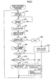
FIG. 2 is a flowchart illustrating a flow of processing of an actuation period change sequence; -
FIG. 3 is a graph illustrating an actuation period with which the monitor is actuated if a battery voltage is not changed; -
FIG. 4 is a graph illustrating an actuation period with which the monitor is actuated if the battery voltage is changed; -
FIG. 5 is a flowchart illustrating a flow of processing of an actuation period change sequence according to a second embodiment; -
FIG. 6 is a graph illustrating an actuation period of a monitor; -
FIG. 7 is a graph illustrating charging characteristics of an olivine iron-type lithium-ion secondary battery; -
FIG. 8 is a flowchart illustrating a flow of processing of an actuation period change sequence according to a third embodiment; and -
FIG. 9 is a flowchart illustrating a flow of processing of an actuation period change sequence according to another embodiment. - A first embodiment will be described with reference to
Figs. 1 to 4 .
Amonitor 30 is connected to asecondary battery 10 and integrally provided therewith. Thesecondary battery 10 is an example of an electric storage device. Themonitor 30 monitors a state of thesecondary battery 10, specifically, voltage, temperature, and current values of the battery. As illustrated inFIG. 1 , themonitor 30 includes aCPU 31, aclock signal oscillator 33, awakeup timer 35, awatchdog timer 37, ameasurement unit 41, an A/D converter 43, aRAM 45, aROM 47, and acommunication interface 49 and a powersupply switch portion 51. TheCPU 31 is an example of a control unit and theRAM 45 is an example of a memory. - The
measurement unit 41 detects voltage (inter-terminal voltage), temperature, and current values of thesecondary battery 10. The A/D converter 43 converts detected values of the voltage, the temperature, and the current of thesecondary battery 10 into digital values and outputs them to theCPU 31. TheCPU 31 receives information such as the voltage and the current of thesecondary battery 10 via the A/D converter 43 and analyzes them to monitor the state of thesecondary battery 10 and check if the battery is in an abnormal state or not. TheRAM 45 is used as a working memory of theCPU 31 and theRAM 45 stores the detected values. TheROM 47 stores a program that performs an actuation period change sequence and data necessary for various calculations. - The power
supply switch portion 51 receives an internal actuation signal S1, a sleep signal Sa and an external actuation signal Sb. Upon receiving one of the signals, the powersupply switch portion 51 switches a power supply state of themonitor 30 between a monitoring state and a sleep state. The sleep state is an example of a low power consumption state. Themonitor 30 has two modes including a measurement mode and a sleep mode that is a low power consumption mode. In the measurement mode, the power supply state of themonitor 30 is maintained in the monitoring state and themonitor 30 detects the voltage, temperature, and current values of thesecondary battery 10 to continuously monitor the state of the battery and power is supplied to all components of themonitor 30. - In the sleep mode, the
monitor 30 is set to alternately in the monitoring state and the sleep state. In the sleep state, themonitor 30 is in a standby state. In the sleep mode, the powersupply switch portion 51 temporally switches the power supply state of themonitor 30 from the sleep state to the monitoring state every actuation period T the powersupply switch portion 51 receives the internal actuation signal S1 from thewakeup timer 35. Themonitor 30 monitors the state of the battery only in the monitoring state, and thereafter, themonitor 30 is switched to be in the sleep state. Thewakeup timer 35 counts time and if the time counted by thewakeup timer 35 reaches the actuation period T, thewakeup timer 35 outputs the internal actuation signal S1 to the powersupply switch portion 51. Accordingly, themonitor 30 is switched from the sleep state to the monitoring state with the certain actuation period T. In the monitoring state, themeasurement unit 41 of themonitor 30 detects a voltage, a current, and a temperature of thesecondary battery 10. - In the sleep state, only the
clock signal oscillator 33, thewakeup timer 35, thecommunication interface 49, and the power supply switch portion of themonitor 30 are supplied with power and supply of power to the other components is stopped, thereby reducing power consumption in thesecondary battery 10. Themonitor 30 is supplied with power from thesecondary battery 10 and therefore, if themonitor 30 is in the sleep state, the consumption power in thesecondary battery 10 can be reduced. - The
monitor 30 is switched between the measurement mode and the sleep mode according to two control signals including the sleep signal Sa and the external actuation signal Sb output from a control system of the load side. In a case that thesecondary battery 10 is mounted to a vehicle, a vehicle-mounted ECU selectively outputs one of the two control signals Sa, Sb. If thesecondary battery 10 is not used for a certain time period and thebattery 10 is not required to be charged, the control system of the load side detects conditions for switching themonitor 30 to the sleep mode and determines that themonitor 30 is to be switched to the sleep mode. In such a case, the control system of the load side outputs the sleep signal Sa to themonitor 30 and theCPU 31 of themonitor 30 receives the sleep signal Sa via thecommunication interface 49. Accordingly, themonitor 30 is switched to be in the sleep mode. Namely, the state of thebattery 10 is basically not changed while themonitor 30 is in the sleep mode. - The load-side control system outputs the external actuation signal Sb to the
monitor 30 to use thebattery 10 and themonitor 30 receives the external actuation signal Sb via thecommunication interface 49. Accordingly, themonitor 30 is switched to be in the measurement mode. Therefore, if themonitor 30 is properly connected to the load and can receive the external actuation signal Sb from the load, themonitor 30 monitors the state of thesecondary battery 10 that is being used. - However, if the
secondary battery 10 is separated from the load to be used or an error or a problem occurs in the communication between themonitor 30 and the load side, themonitor 30 does not receive the external actuation signal Sb from the load side. Therefore, themonitor 30 remains in the sleep mode and monitors the battery repeatedly with the certain period. If thesecondary battery 10 is charged improperly, thebattery 10 may be in an abnormal state such as overcharge or over discharge during a period between a current monitoring and a subsequent monitoring. - In the present embodiment, if determining that a current detected battery voltage of the
secondary battery 10 is changed from a previous detected battery voltage in the sleep mode, themonitor 30 changes the actuation period T. Specifically, in response to such determination, theCPU 31 shortens the actuation period T so that themonitor 30 monitors thesecondary battery 10 more frequently with a shorter period. Accordingly, it can be detected promptly that thesecondary battery 10 is used in a condition that themonitor 30 cannot receive the external actuation signal Sb from the load side. Further, the voltage of thesecondary battery 10 does not reach the prohibited level. - An actuation period change sequence will be explained with reference to
FIG. 2 . In the actuation period change sequence, the actuation period T of themonitor 30 is changed. It is assumed that thesecondary battery 10, thecharger 20, the relay R, and themonitor 30 are mounted to the load side and a time set to thewakeup timer 35, that is, the initial value of the actuation period T is 60 seconds, for example. A number of continuous changes K that will be described later is zero. - The actuation period change sequence starts in response to detection of conditions for switching the
monitor 30 from the measurement mode to the sleep mode and output of the sleep signal Sa from the load side to themonitor 30. - If the
CPU 31 receives the sleep signal Sa, themonitor 30 is switched to the sleep mode and set to be in the sleep state that reduces consumption power. In the sleep mode, only theclock signal oscillator 33, thewakeup timer 35, thecommunication interface 49, and the powersupply switch portion 51 are supplied with power to be operated and supply of power to the other components is stopped (S10). - After the
monitor 30 is switched to the sleep state, thewakeup timer 35 starts counting time and detects whether the counted time reaches the set time. If the time counted by thewakeup timer 35 reaches the set time (S20), thewakeup timer 35 outputs the internal actuation signal S1 to the powersupply switch portion 51. The initial value of the set time is 60 seconds. If 60 seconds passes after themonitor 30 becomes in the sleep state, thewakeup timer 35 outputs the internal actuation signal S1 to the powersupply switch portion 51. - If receiving the internal actuation signal S1, the power
supply switch portion 51 supplies power to each component of themonitor 30 to actuate the monitor 30 (S20, S30). Then, themeasurement unit 41 detects voltage, temperature, and current values of the secondary battery 10 (S40). - The values detected by the
measurement unit 41 are converted into digital values by the A/D converter 43 and transferred to theCPU 31 and stored in the RAM 45 (S40). TheCPU 31 determines whether the current detected value changes (S50). Specifically, theCPU 31 compares the current detected value and a previous detected value stored in theRAM 45 and determines whether the current detected value of thesecondary battery 10 changes from the previous detected value (S50). If the current detected voltage of thesecondary battery 10 changes from the previous detected voltage by at least a predetermined value (for example, 0.05 V), it is preferably determined that the detected battery value is changed. Accordingly, it is not erroneously determined that the battery value is changed according to very small change in the battery voltage that may be caused due to a situation or an environment in which themonitor 30 is used. Such a very small change in the battery voltage may be caused even if improper charging is not executed. - No previous detected value is stored in the
RAM 45 in the first determination just after themonitor 30 is switched to the sleep mode. Therefore, the detected value that is most recently detected in the measurement mode immediately before themonitor 30 is switched to the sleep mode is used as the previous detected value. If theCPU 31 determines that the current detected value does not change from the previous detected value (S50), the process proceeds to S70. - In S70, the set time of the
wakeup timer 35 is maintained to be the initial value. Then, the process returns to S10 and themonitor 30 is switched to the sleep state again. Then, if thewakeup timer 35 determines that the counted time reaches the set time, thetimer 35 outputs the internal actuation signal S1 to the powersupply switch portion 51 and accordingly, themonitor 30 is actuated (S20, S30). - In such a manner, the
monitor 30 is actuated and detects the voltage, temperature, and current values of thesecondary battery 10. If no change is detected in voltage of thesecondary battery 10, a negative decision (NO) is made in S50 and the number of continuous changes K is set to be zero (S60). Therefore, the set time of thewakeup timer 35 is maintained to be the initial value (S70). - Therefore, as long as the detected value of the battery voltage is not changed from the previous detected value, the
monitor 30 is repeatedly actuated to monitor the state of thesecondary battery 10 at the initial interval as illustrated inFIG. 3 . - The
secondary battery 10, thecharger 20, the relay R and themonitor 30 may be removed and separated from the load, and thesecondary battery 10 may be charged with power supplied from an external device or may be charged by a charger other than the built-incharger 20. In such a case, even if themonitor 30 is in the sleep mode, the voltage of thesecondary battery 10 rises as illustrated inFIG. 4 and it is determined that the current detected voltage is changed from the previous detected voltage in S50. Accordingly, the number of continuous changes K is increased by one (S80), and it is determined that the increased number of continuous changes K is less than a threshold number of changes Kth (for example two) in S90. Further, it is determined that the current detected value is equal to or less than the threshold voltage Vth (S100: No). Then, theCPU 31 changes the set time of thewakeup timer 35 to a first change value (for example, 30 seconds) and shortens the actuation period T of themonitor 30 in S110. For example, as illustrated inFIG. 4 , theCPU 31 changes the set time of thewakeup timer 35 from 60 seconds to 30 seconds and changes the actuation period T of themonitor 30 from the initial value of 60 seconds to 30 seconds. - After changing the actuation period T to the first change value, the
monitor 30 is actuated at an interval of the first change value in subsequent monitoring. After changing the actuation period T, the process returns to S10. Then, the process proceeds to S20, S30 and S40 and if it is determined that the battery voltage does not change (S50: No), theCPU 31 resets the number of continuous changes K to be zero (S60) and also resets the set time period of thewakeup timer 35 to the initial value (S70). If it is again determined that the current battery voltage changes from the previous detected value (S50: Yes), and it is determined that the current detected value detected in S40 is equal to or less than the threshold voltage Vth (S100: No), theCPU 31 does not change the set time of thewakeup timer 35 and keeps the first change value (S110). The threshold voltage Vth is preferably close to the full charge voltage of thesecondary battery 10. - If the battery voltage of the
secondary battery 10 continuously changes with respect to a time axis as illustrated inFIG. 4 , for example proportionally, themonitor 30 is repeatedly actuated at an interval of 30 seconds to monitor thesecondary battery 10. - If the detected battery voltage changes consecutively several times, the
CPU 31 determines that thesecondary battery 10 is used in condition where the monitor cannot receive the external actuation signal Sb from the load side. If determining that the number of continuous changes K is over the threshold number Kth (S90: No), theCPU 31 changes the set time of thewakeup timer 35 to be a second change value that is shorter than the first change value (for example, 20 seconds) in S120. Accordingly, the actuation period T of themonitor 30 is further shortened. Therefore, the voltage is detected for several times at a shortened actuation period T. This reduces time required to determine that thesecondary battery 10 is used in an improper state. - In the present embodiment, the actuation period T is changed to be shortened if the
secondary battery 10 is improperly used. Therefore, compared to a case where the actuation period T of themonitor 30 is not changed from the initial value even if thesecondary battery 10 is improperly used, it is promptly detected that thesecondary battery 10 is used in an improper state that themonitor 30 cannot receive the external actuation signal Sb from the load side. If detecting that thesecondary battery 10 is used in an improper condition that themonitor 30 cannot receive the external actuation signal Sb from the load side, theCPU 31 of themonitor 30 performs an informing process that informs an error using an error notification lamp or a buzzer for example (S130). - If the actuation period T is kept to be long, the
secondary battery 10 is not monitored by themonitor 30 for a long time. Thus, if thesecondary battery 10 is charged for a long time without monitoring and the battery voltage reaches a prohibited level, overcharge or over discharge may be caused in thesecondary battery 10 and thesecondary battery 10 may become in an abnormal state. However, in the present embodiment, the actuation period T of themonitor 30 is shortened and this shortens a monitoring interval of thesecondary battery 10. Therefore, theCPU 31 may disconnect the relay R (S130) to stop charging before thesecondary battery 10 is overcharged. Therefore, thesecondary battery 10 is not overcharged. - In determining that the number of continuous changes K is less than the threshold number Kth (S90: Yes) and determining that the current detected value that is detected in S40 is greater than the threshold voltage Vth (S100: Yes), the
CPU 31 changes the set time of thewakeup timer 35 to the second change value (S120). Accordingly, as illustrated inFIG. 4 , theCPU 31 may further shorten the actuation period T of themonitor 30, and thesecondary battery 10 is not overcharged. - Next, a second embodiment will be described with reference to
FIGS. 5 to 7 . In the first embodiment, the voltage of thesecondary battery 10 proportionally changes with respect to the time axis and changes the actuation period T of themonitor 30 from 60 seconds to 30 seconds. - In the second embodiment, the
CPU 31 compares the current detected voltage and the previous detected voltage and obtains a change amount of the battery voltage every time determining that the current voltage changes from the previous voltage. Specifically, if determining that the current detected voltage changes from the previous detected voltage (S50: Yes), theCPU 31 computes a change amount between the previous detected voltage and the current detected voltage (S210). As the change amount becomes greater, theCPU 31 changes the set time of thewakeup timer 35 to be a shorter value (S220). Accordingly, the greater the change amount of the detected battery voltage values is, the shorter the actuation period T becomes. For example, if the battery voltage changes along a substantially quadratic curve with respect to the time axis as illustrated inFIG. 6 , the actuation period T of themonitor 30 is changed to be shorter as time passes. - In the second embodiment, if the change amount of the battery voltages becomes larger and the current detected voltage is close to the full-charge voltage, the actuation period T is further shortened. Therefore, the
monitor 30 monitors thesecondary battery 10 more frequently. Therefore, thesecondary battery 10 is not overcharged. An olivine-type lithium-ion iron second battery has characteristics as illustrated inFIG. 6 , and in the olivine-type lithium-ion iron second battery, the voltage rises drastically at a terminal stage of charging. The olivine-type iron battery is a kind of lithium-ion batteries and has a positive electrode made of olivine-type iron phosphate, that is, lithium iron phosphate (LiFePO4) and a negative electrode made of, for example, carbon. The olivine-type lithium-ion iron secondary battery has a full-charge voltage of about 3.5 V as illustrated inFIG. 7 . Therefore, if the olivine-type lithium-ion iron secondary battery is set such that the voltage drastically rises in a range between 3.45 V and 3.5V that is close to the full-charge voltage, the actuation period T is also shortened at the voltage between 3.45 V and 3.5 V. Accordingly, the olivine-type lithium-ion ironsecondary battery 10 can be monitored more frequently at the voltage close to the full-charge voltage. Therefore, the olivine-type lithium-ion iron secondary battery is not overcharged. - Next, a third embodiment will be described with reference to
FIG. 8 . An actuation period change sequence of the third embodiment is substantially same as the sequence of the second embodiment including steps S10 to S220 and additionally includes processing of S3 and S5 inFIG. 7 . Therefore, the processing of S3 and S5 will be explained. - As shown in
FIG. 8 , in the third embodiment, if theCPU 31 detects that the conditions for switching themonitor 30 to the sleep mode are satisfied and receives the sleep signal Sa output from the load side, the CPU 31of themonitor 30 determines whether the most recent battery voltage of thesecondary battery 10 detected in the measurement mode is close to a full-charge voltage or not (S3). Specifically, theCPU 31 compares the most recent battery voltage to a threshold voltage Vth that is previously set (a value close to the full-charge voltage). If determining that the most recent battery voltage is higher than the threshold voltage Vth, theCPU 31 determines that the most recent battery voltage is close to the full-charge voltage (S3: Yes). If determining that the most recent battery voltage is less than the threshold voltage, theCPU 31 determines that the most recent battery voltage Vth is not close to the full-charge voltage (S3: No). - If the
CPU 31 determines that the most recent battery voltage is not close to the full-charge voltage (NO: S3), the process proceeds to S10. Processing executed after S10 is same as that in the second embodiment. In the sleep state, if the detected voltage of thesecondary battery 10 is not changed from the previous detected value (S50: No), themonitor 30 is actuated with an actuation period T of 60 seconds to monitor the secondary battery 10 (S70). If the current detected voltage is changed from the previous detected value (S50: Yes), the actuation period T is changed (S60). - Next, if the
CPU 31 determines that the most recent battery voltage is close to the full-charge voltage (YES: S3), the process proceeds to S5. In S5, theCPU 31 changes the set time of thewakeup timer 35 to a time shorter than an initial value. The initial value of the set time of thewakeup timer 35 is 60 seconds, and the set time is changed to a time shorter than that. For example, 30 seconds is set to thewakeup timer 35 in S5. Accordingly, immediately after being switched to the sleep mode, themonitor 30 is actuated with an actuation period T that is shorter than the initial setting and monitors thesecondary battery 10. - In such a manner, if the voltage of the
secondary battery 10 is close to the full-charge voltage before themonitor 30 being switched from the measurement mode to the sleep mode, the actuation period T of themonitor 30 is set to a small value. Therefore, the secondary battery is not overcharged. - The present invention is not limited to the above description and the drawings. For example, the following embodiments are covered by the technological scope of the invention.
- (1) In the above embodiments, the
monitor 30 monitors the state of thesecondary battery 10. However, the target to be monitored by themonitor 30 is necessarily a storage element (electricity storing element), and the state of a capacitor may be monitored by themonitor 30. Further, in the above embodiments, the control device is theCPU 31. However, the control device may be a hardware circuit. - (2) In the above embodiments, if the voltage of the
secondary battery 10 is changed from the previous detected value, the actuation period T of themonitor 30 is changed. For example, theCPU 31 may detect a temperature of thesecondary battery 10 and determine whether the detected temperature of thesecondary battery 10 is changed from the previous detected value. If determining that the detected temperature is changed from the previous value, theCPU 31 may change the actuation period T of themonitor 30. - Besides the battery temperature, the information denoting the state of the
secondary battery 10 may include any information from which theCPU 31 can detect the possibility of occurring abnormality of the battery such as a state of charge (SOC), a current value, or an internal pressure of the battery. - A current of the
secondary battery 10 may be detected to detect the state of thebattery 10. A dark current dissipated by thebattery 10 while a vehicle being parked may be detected to determine whether the actuation period T may be changed or not. Specifically, in a system in which the dark current dissipated by thesecondary battery 10 while a vehicle being parked is 100mA or less, if determining that the dark current is a normal value and is less than 100 mA, theCPU 31 sets the actuation period T of themonitor 30 to 60 seconds that is an initial value. - If determining that the dark current is 100 mA or higher, the
CPU 31 may change the actuation period T of themonitor 30 from 60 seconds to 30 seconds or may shorten the actuation period T in a stepwise manner according to the level of the dark current. For example, in thesecondary battery 10 having a capacity of 60 Ah, the actuation period T is changed according to the level of the dark current as follows. If the dark current is from 100 mA to 0.1 CA (6A), the actuation period T is set to 30 seconds. If the dark current is from 0.1 CA (6A) to 0.5 CA (30A), the actuation period T is set to 20 seconds. If the dark current is 0.5 CA (30A) or greater, the actuation period T is set to 10 seconds. - The actuation period T may be determined based on a plurality of detected values. For example, a current and a battery voltage may be detected and the
CPU 31 may detect whether each of the values of the current and the battery voltage is equal to or greater than a corresponding certain level. If both of the detected values of the current and the battery voltage are the certain level or greater, the actuation period T may be further shortened as compared to a case in which only one of them is greater than the corresponding certain level. In such a case, themeasurement unit 41 is a current sensor that detects a current flowing through thesecondary battery 10, and a current is detected by the current sensor and the detected value corresponds to a detected current. - (3) In the above embodiments, the actuation period T of the
monitor 30 is changed if the detected value of thesecondary battery 10 is changed from the previous detected value. The target value to be compared with the current detected value of thesecondary battery 10 may be a value that is detected prior to the last value that is detected at last or a reference value that is previously stored in theRAM 45. Therefore, if the current detected value of thesecondary battery 10 is changed from the value detected prior to the last value or the reference value, the actuation period T of themonitor 30 maybe changed. - (4) In the above embodiments, the voltage of the
secondary battery 10 is increased from the previous detected value (charging). However, the voltage of thesecondary battery 10 may be decreased from the previous detected value (discharging). Also in the case where the voltage of thesecondary battery 10 is decreased from the previous detected value, the actuation period T may be shortened to shorten the monitoring interval at which themonitor 30 is monitored. - (5) In the above embodiments, the
monitor 30 is switched from the measurement mode to the sleep mode if theCPU 31 of themonitor 30 receives the sleep signal Sa output from the side of load. However, themonitor 30 may detect the conditions for switching to the sleep mode without receiving any signal from the external device and if detecting the conditions, themonitor 30 may be switched to the sleep mode. - (6) In the above embodiments, each of the sleep signal Sa and the external actuation signal Sb is an independent signal. However, the two signals Sa and Sb may be configured with a single signal. The single signal may be set to a high level or a low level to control switching the mode of the
monitor 30. - (7) In the above embodiments, the actuation period T of the
monitor 30 is changed if the voltage of thesecondary battery 10 is changed from the previous detected value. In addition to this, theCPU 31 may further detects if a current is flowing through thesecondary battery 10 to determine whether to change the actuation period T or not. TheCPU 31 changes the actuation period T of themonitor 30 if detecting that the current detected voltage of thesecondary battery 10 is changed from the previous detected value and a current is flowing through thesecondary battery 10. - Accordingly, the following effects are obtained. Generally, the battery voltage changes for a while after completion of charging or discharging. Therefore, if the actuation period T is changed only based on a change in the battery voltage, the actuation period T may be changed even in an ordinary state where the battery is not charged improperly. However, if the actuation period is changed based on a change in the battery voltage and detection that the current is flowing through the battery, the actuation period T is not changed in the ordinary state. Thus, the actuation period T is changed only when the battery is used (charged) improperly.
- (8) In the second embodiment, the larger the change amount of the measured battery voltage value is, the more the actuation period T is shortened. The actuation period T may be changed in any other methods according to the change amount of the detected value. For example, the actuation period T of the
monitor 30 may be changed in accordance with any one of the following patterns. - As illustrated in
FIG. 7 , in the olivine-type lithium ion iron secondary battery, the full-charge voltage is about 3.5 V, and the battery is preferably used with the charged voltage being between 3.3 V and 3.5 V. In this case, a range of use E of the battery is 200 mV from 3.3 V to 3.5 V and the battery can be preferably used in this range, and 10% thereof is 20 mV. If the detected value is not changed from the previous value and the actuation period T is set to the initial value of 60 seconds, the actuation period T may be changed in the following methods. - Pattern 1: If the detected value is changed from the previous detected value by 20 mV that is 10% of the range of use, the actuation period T is changed from 60 seconds to 30 seconds that is a half of the initial value.
Pattern 2: If the detected value is changed from the previous detected value by 40 mV that is 20% of the range of use, the actuation period T is changed from 60 seconds to 15 seconds that is a quarter of the initial value.
Pattern 3: If the detected value is changed from the previous detected value by 20 mV and the actuation period T is changed from the initial value of 60 seconds to 30 seconds and then the subsequent detected value is changed from the previous value by 40 mV , the actuation period T is changed from 30 seconds to 15 seconds that is a half of 30 seconds. If the detected value is changed by the change amount same as the previous change amount of 20 mV, the actuation period T is not changed and maintained to be 30 seconds. - The actuation period T may be changed by multiplying the actuation period T by a constant (1/2 or 1/4) corresponding to the change amount of the detected value as described above, and further, the actuation period T may be changed by subtracting a constant (20 seconds or 40 seconds) that is determined corresponding to the change amount of the detected value from the current actuation period T.
- (9) In the above embodiments, the actuation period T of the
monitor 30 is changed if the battery voltage of thesecondary battery 10 is changed from the previous detected value. However, the actuation period T may be changed if theCPU 31 detects that the battery voltage of thesecondary battery 10 is not changed from the previous detected value or a reference value. - Specifically, if the current detected value is not changed from the previous detected value, it is unlikely that the
secondary battery 10 is used improperly. Thus, even if the actuation period of themonitor 30 is extended, it is unlikely that any error is caused in thesecondary battery 10. The actuation period T is 60 seconds that is the initial value and if the current detected value is not changed from the previous value, the actuation period T may preferably be set to 90 seconds or 120 seconds that is longer than the initial value. The actuation period T becomes longer and this reduces the power consumption of themonitor 30. - The actuation period T may be changed if the battery voltage of the
secondary battery 10 is not changed from the previous detected value or the reference value, and also the actuation period T may be changed if the current detected value is changed from the previous detected value. - As illustrated in
FIG. 9 , if determining that the current detected voltage changes (S50: Yes), theCPU 31 computes a change amount between the previous detected value and the current detected value (S210), and theCPU 31 changes the set time of thewakeup timer 35 to be a shorter value as the computed change amount is greater (S220). If determining that the current detected voltage does not change (s50: No), theCPU 31 may change the set time of thewakeup timer 35 to be a value that is longer than the initial value. - 10: Secondary battery, 20: Charger, 30: Monitor, 31: CPU, 35: Wakeup timer, 41: Measurement unit, T: Actuation period, S1: Internal actuation signal, Sa: Sleep signal, Sb: External actuation signal
Claims (9)
- A monitor monitoring an electric storage device comprising:a measurement unit configured to detect a state of the electric storage device and obtain a detected value:a power supply switch portion configured to switch a power supply state of the monitor between a monitoring state and a low power consumption state that requires lower power than the monitoring state; anda wakeup timer to which actuation time is set and configured to start counting time in response to switching to the low power consumption state by the power supply switch portion and continue counting time until reaching the actuation time and output an actuation signal if reaching the actuation time, wherein:the power supply switch portion switches the power supply state of the monitor from the low power consumption state to the monitoring state every time the wakeup timer outputs the actuation signal, the monitor further comprising:a control unit configured to:control the measurement unit to detect the state of the electric storage device and obtain the detected value when the power supply state of the monitor is set in the monitoring state by the power supply switch portion;compare the detected value and a reference value; andchange the actuation time according to a comparison result of the detected value and the reference value.
- The monitor according to claim 1, further comprising a memory configured to store a previous detected value that is detected prior to the detected value, wherein:the control unit is further configured to
compare the detected value and the previous detected value;
determine if the detected value changes from the previous detected value; and
shorten the actuation time according to first determination that the detected value changes from the previous detected value. - The monitor according to claim 1, wherein:the control device is further configured to:obtain a change amount according to comparison between the detected value and the previous detected value; andchange the actuation time according to the change amount.
- The monitor according to claim 2, wherein:the control device is further configured to:obtain a change amount according to comparison between the detected value and the previous detected value; andshorten the actuation time to be shorter as the change amount becomes greater.
- The monitor according to any one of claims 2 to 4, wherein the control device is further configured to:determine if the detected value is close to a full-charge voltage when the power supply switch portion switches the power supply state to the low power consumption state; andshorten the actuation time from an initial value according to second determination that the detected value is close to the full-charge voltage.
- The monitor according to any one of claims 2 to 5, further comprising a memory configured to store previous detected voltage, wherein:the measurement unit detects voltage and a current value of the electric storage device;the control device is further configured to:compare the detected voltage and the previous detected voltage;determine if the detected voltage changes from the previous detected voltage and if current is flowing through the electric storage device based on the detected current value and make third determination that the detected voltage changes from the previous detected voltage and the current is flowing through the electric storage device; andshorten the actuation time according to the third determination.
- The monitor according to any one of claims 2 to 4, wherein the electric storage device is an olivine-type lithium-ion iron secondary battery having a positive electrode made of olivine-type iron phosphate.
- The monitor according to any one of claims 2 to 7, further comprising a memory configured to store a previous detected value that is detected prior to the detected value, wherein:the control unit is further configured to
compare the detected value and the previous detected value;
determine if the detected value changes from the previous detected value; and
extend the actuation time according to fourth determination that the detected value does not change from the previous detected value. - The monitor according to claim 1, further comprising a memory configured to store a previous detected value that is detected prior to the detected value, wherein:the control unit is further configured to
compare the detected value and the previous detected value;
determine if the detected value changes from the previous detected value; and
extend the actuation time according to fourth determination that the detected value does not change from the previous detected value.
Applications Claiming Priority (3)
| Application Number | Priority Date | Filing Date | Title |
|---|---|---|---|
| JP2011197077 | 2011-09-09 | ||
| JP2012176839 | 2012-08-09 | ||
| JP2012197187A JP2014052296A (en) | 2011-09-09 | 2012-09-07 | Monitoring device |
Publications (3)
| Publication Number | Publication Date |
|---|---|
| EP2574948A2 true EP2574948A2 (en) | 2013-04-03 |
| EP2574948A3 EP2574948A3 (en) | 2013-04-10 |
| EP2574948B1 EP2574948B1 (en) | 2017-08-30 |
Family
ID=47074534
Family Applications (1)
| Application Number | Title | Priority Date | Filing Date |
|---|---|---|---|
| EP12006310.2A Active EP2574948B1 (en) | 2011-09-09 | 2012-09-07 | Electric storage device monitor |
Country Status (3)
| Country | Link |
|---|---|
| US (1) | US8779729B2 (en) |
| EP (1) | EP2574948B1 (en) |
| JP (1) | JP2014052296A (en) |
Cited By (2)
| Publication number | Priority date | Publication date | Assignee | Title |
|---|---|---|---|---|
| DE102013219291A1 (en) * | 2013-09-25 | 2015-03-26 | Robert Bosch Gmbh | A method of storing a fault of a cell monitoring circuit and lithium-ion battery |
| EP2951600A4 (en) * | 2013-01-30 | 2016-12-28 | St-Ericsson Sa | Method and device for measuring state of charge of mobile terminal |
Families Citing this family (91)
| Publication number | Priority date | Publication date | Assignee | Title |
|---|---|---|---|---|
| US10078101B2 (en) * | 2009-04-21 | 2018-09-18 | Johnstech International Corporation | Wafer level integrated circuit probe array and method of construction |
| US9225185B2 (en) * | 2011-10-21 | 2015-12-29 | Samsung Electronics Co., Ltd. | Method and apparatus for controlling charging in electronic device |
| US9312712B2 (en) * | 2012-07-26 | 2016-04-12 | Samsung Sdi Co., Ltd. | Method and system for controlling charging parameters of a battery using a plurality of temperature ranges and counters and parameter sets |
| EP2746874A3 (en) * | 2012-12-19 | 2017-11-08 | Seiko Epson Corporation | Electronic device having power generation function, control method of electronic device having power generation function, and portable electronic device having power generation function, and control method of portable electronic device having power generation function |
| US10247680B2 (en) * | 2013-06-28 | 2019-04-02 | Sensors & Software Inc. | System and method for measurement of material property using variable reflector |
| DE102013218402A1 (en) * | 2013-09-13 | 2015-03-19 | Krones Ag | Device and method for performing special functions of a transport device in a container treatment plant |
| DE102013219282A1 (en) * | 2013-09-25 | 2015-03-26 | Robert Bosch Gmbh | Method for checking a sleep mode of a cell monitoring circuit and lithium-ion secondary battery |
| DE102013225243A1 (en) | 2013-12-09 | 2015-06-11 | Robert Bosch Gmbh | A method for transmitting a minimum and / or a maximum value of a battery system parameter and battery system for carrying out such a method |
| JP6232593B2 (en) * | 2014-02-25 | 2017-11-22 | 株式会社Joled | Manufacturing method of display device |
| TWI651539B (en) | 2014-03-10 | 2019-02-21 | 美商瓊斯科技國際公司 | Wafer-level integrated circuit probe array and construction method |
| US9797938B2 (en) * | 2014-03-28 | 2017-10-24 | International Business Machines Corporation | Noise modulation for on-chip noise measurement |
| US9740265B2 (en) | 2014-05-12 | 2017-08-22 | Qualcomm Incorporated | Electronic device for extending battery life in mobile applications |
| KR102165937B1 (en) * | 2014-05-30 | 2020-10-14 | 삼성전자주식회사 | Method and apparatus for managing battery |
| US10481290B2 (en) * | 2014-07-11 | 2019-11-19 | Schlumberger Technology Corporation | Generalized directional measurements and using symmetrized and anti-symmetrized angles to indicate orientation of anisotropy and formation boundaries |
| US10491014B2 (en) * | 2014-07-15 | 2019-11-26 | Dell Products, L.P. | Battery management system and method for extending time until a battery reaches an over-discharged state during storage of an information handling system |
| WO2016023941A1 (en) * | 2014-08-12 | 2016-02-18 | Omicron Electronics Gmbh | Test system and method for testing a circuit breaker |
| CN105807146B (en) * | 2014-12-31 | 2018-10-02 | 清华大学 | Electrostatic apparatus for measuring distribution |
| JP2018058379A (en) * | 2015-02-20 | 2018-04-12 | パナソニックIpマネジメント株式会社 | Battery condition measurement device and control method |
| JP2018058380A (en) * | 2015-02-20 | 2018-04-12 | パナソニックIpマネジメント株式会社 | Battery condition measurement device and control method |
| WO2016144709A1 (en) | 2015-03-06 | 2016-09-15 | Gatekeeper Systems, Inc. | Low-energy consumption location of movable objects |
| TWI704352B (en) * | 2015-03-13 | 2020-09-11 | 義大利商探針科技公司 | Contact probe for a testing head |
| JP6791123B2 (en) * | 2015-03-25 | 2020-11-25 | 株式会社Gsユアサ | Power storage element monitoring device, power storage device and power storage element monitoring method |
| US9904349B2 (en) * | 2015-03-27 | 2018-02-27 | Intel Corporation | Technologies for managing power of an embedded controller during a low-power state |
| GB2538517A (en) * | 2015-05-19 | 2016-11-23 | I2I Pipelines Ltd | Improved pipe pig |
| WO2017022169A1 (en) * | 2015-07-31 | 2017-02-09 | パナソニックIpマネジメント株式会社 | Battery control device, electronic apparatus, battery pack, and battery control method |
| US10578462B2 (en) * | 2015-08-11 | 2020-03-03 | Continental Teves Ag & Co. Ohg | Device for measuring a measurement variable |
| US10060172B2 (en) * | 2015-08-21 | 2018-08-28 | Magna Closures Inc. | Variable resistance conductive rubber sensor and method of detecting an object/human touch therewith |
| CN205003199U (en) * | 2015-09-02 | 2016-01-27 | 丹纳赫(上海)工业仪器技术研发有限公司 | Portable type measurement unit |
| CN204989252U (en) * | 2015-09-02 | 2016-01-20 | 丹纳赫(上海)工业仪器技术研发有限公司 | Test wire subassembly and measuring device |
| KR102059617B1 (en) * | 2015-09-02 | 2020-02-11 | 주식회사 엘지화학 | Method and for charging control apparatus for battery pack |
| US10197526B2 (en) | 2015-09-03 | 2019-02-05 | Honeywell International Inc. | FET and fiber based sensor |
| US9927474B1 (en) * | 2015-09-03 | 2018-03-27 | Walter S. Bierer | Phase identification on a grounded electrical power system |
| US10001541B2 (en) * | 2015-09-04 | 2018-06-19 | Gatekeeper Systems, Inc. | Magnetometer and accelerometer calibration for cart navigation system |
| CN108137074B (en) | 2015-09-04 | 2021-12-03 | 看门人系统公司 | Motion estimation for wheeled vehicles |
| EP3141911B1 (en) * | 2015-09-08 | 2021-03-24 | Hioki Denki Kabushiki Kaisha | Voltage detecting probe and measuring device |
| TWI545332B (en) * | 2015-09-10 | 2016-08-11 | 旺玖科技股份有限公司 | Magneto-impedance sensor device and method for fafbicating the same |
| KR101714518B1 (en) * | 2015-09-11 | 2017-03-22 | 현대자동차주식회사 | Method and Apparutus for Preventing Excess of Dark Current In Telematics Terminal |
| JP6606384B2 (en) * | 2015-09-15 | 2019-11-13 | オークマ株式会社 | Resolver for rotational position detection using resin bearings |
| KR102340973B1 (en) * | 2015-09-18 | 2021-12-17 | 삼성전자주식회사 | Device and method for semiconductor test and data analyze device |
| CN106558507B (en) * | 2015-09-23 | 2019-04-26 | 中芯国际集成电路制造(北京)有限公司 | Test structure and forming method thereof, test method |
| KR102479184B1 (en) * | 2015-12-07 | 2022-12-19 | 삼성전자주식회사 | Apparatus and Method for exchange probe |
| WO2017108107A1 (en) * | 2015-12-22 | 2017-06-29 | Volvo Truck Corporation | A method and system for monitoring electrical insulation resistance in an electric system |
| US10126338B2 (en) * | 2015-12-30 | 2018-11-13 | Advanced Digital Broadcast S.A. | System and methods for adaptive power consumption based on source impedance |
| JP6597394B2 (en) * | 2016-02-29 | 2019-10-30 | オムロン株式会社 | Arc generating position detecting device and arc generating position detecting method |
| JP6769046B2 (en) * | 2016-03-01 | 2020-10-14 | 株式会社Gsユアサ | Power storage element monitoring device, power storage element module, SOC estimation method |
| CN105807518B (en) * | 2016-05-19 | 2019-01-01 | 武汉华星光电技术有限公司 | Liquid crystal display panel |
| US10156863B2 (en) * | 2016-06-03 | 2018-12-18 | Emerson Electric Co. | Systems and methods for controlling appliances |
| JP6755136B2 (en) * | 2016-07-13 | 2020-09-16 | 株式会社デンソーテン | Voltage detector and voltage detection method |
| DE102016114146A1 (en) * | 2016-08-01 | 2018-02-01 | Endress+Hauser Flowtec Ag | Test system for checking electronic connections |
| KR102530408B1 (en) * | 2016-08-02 | 2023-05-09 | 세르보센스 (에스엠씨) 엘티디. | High Resolution Absolute Encoder |
| US10476432B2 (en) * | 2016-08-05 | 2019-11-12 | Sunpower Corporation | High throughput system for photovoltaic UV degradation testing |
| US9983255B2 (en) * | 2016-08-15 | 2018-05-29 | The Boeing Company | Apparatus for testing dielectric breakdown voltage |
| US10012686B2 (en) * | 2016-08-15 | 2018-07-03 | Tektronix, Inc. | High frequency time domain reflectometry probing system |
| US9970980B2 (en) * | 2016-08-26 | 2018-05-15 | Infineon Technologies Ag | Test circuit for stress leakage measurements |
| US10324140B2 (en) * | 2016-09-06 | 2019-06-18 | Littelfuse, Inc. | Zero sequence sensing apparatus and method |
| JP6768425B2 (en) * | 2016-09-08 | 2020-10-14 | キヤノン株式会社 | Information processing equipment, its control method, and programs |
| US10247796B2 (en) * | 2016-09-13 | 2019-04-02 | General Electric Company | System and method for marking an object during a magnetic resonance imaging scan |
| EP3315918B1 (en) * | 2016-10-26 | 2018-08-22 | Samsung SDI Co., Ltd. | Crash detection circuit for the detection of a crash of a vehicle |
| US10255468B2 (en) * | 2016-10-28 | 2019-04-09 | Avery Dennison Retail Information Services, Llc | Transmission RFID test systems |
| US10132860B2 (en) * | 2016-10-28 | 2018-11-20 | Nxp Usa, Inc. | Systems and methods for testing package assemblies |
| US10198336B2 (en) * | 2016-10-28 | 2019-02-05 | Hewlett Packard Enterprise Development Lp | Module statuses corresponding to slot locations |
| US10270272B2 (en) * | 2016-12-28 | 2019-04-23 | Silicon Laboratories Inc. | Charge measurement in a system using a pulse frequency modulated DC-DC converter |
| US10996281B2 (en) | 2016-12-28 | 2021-05-04 | Silicon Laboratories Inc. | Charge measurement calibration in a system using a pulse frequency modulated DC-DC converter |
| US10175267B2 (en) * | 2016-12-29 | 2019-01-08 | Novatek Microelectronics Corp. | Current measurement circuit for measuring current consumption of circuit system |
| US10401319B2 (en) * | 2017-01-16 | 2019-09-03 | The Boeing Company | Structural health monitoring system |
| DE102017202594A1 (en) * | 2017-02-17 | 2018-08-23 | Robert Bosch Gmbh | Method for detecting electrical faults in a power supply of a consumer |
| CN106872758A (en) * | 2017-02-23 | 2017-06-20 | 惠州Tcl移动通信有限公司 | A kind of mobile terminal first voltage calculating method and system when starting |
| WO2018165178A1 (en) | 2017-03-08 | 2018-09-13 | Gatekeeper Systems, Inc. | Navigation systems for wheeled carts |
| JP6790931B2 (en) * | 2017-03-14 | 2020-11-25 | 株式会社デンソー | Battery state estimator |
| US10594001B2 (en) * | 2017-05-08 | 2020-03-17 | Packet Digital, Llc | Smart battery |
| US10794837B2 (en) * | 2017-07-12 | 2020-10-06 | Rohde & Schwarz Gmbh & Co. Kg | On-wafer calibration device |
| CN109587605A (en) * | 2017-09-28 | 2019-04-05 | 富泰华工业(深圳)有限公司 | Electromagnetic sensor |
| US10208772B1 (en) * | 2018-01-12 | 2019-02-19 | Altec Industries, Inc. | Position-determining actuator |
| US10466277B1 (en) * | 2018-02-01 | 2019-11-05 | John Brooks | Scaled and precise power conductor and current monitoring |
| US10348283B1 (en) | 2018-02-22 | 2019-07-09 | Silicon Laboratories Inc. | Low power switched-capacitor comparator |
| JP7236860B2 (en) * | 2018-03-26 | 2023-03-10 | 日立Astemo株式会社 | voltage detector |
| US10423174B1 (en) | 2018-04-23 | 2019-09-24 | Silicon Laboratories Inc. | PFM power management system with autonomous mode switching |
| GB201808797D0 (en) * | 2018-05-30 | 2018-07-11 | Rolls Royce Plc | Power system |
| GB201808798D0 (en) | 2018-05-30 | 2018-07-11 | Rolls Royce Plc | Angle determination for a generator |
| CN109490966B (en) * | 2018-06-15 | 2020-11-03 | 中国科学院地质与地球物理研究所 | Magnetotelluric measurement system |
| US10725192B2 (en) * | 2018-10-10 | 2020-07-28 | United States Of America, As Represented By The Secretary Of The Navy | Passive magnetic field detector |
| US10823759B2 (en) * | 2018-11-05 | 2020-11-03 | Xilinx, Inc. | Test system and method of testing a wafer for integrated circuit devices |
| US20220189217A1 (en) * | 2019-03-26 | 2022-06-16 | Hitachi Astemo, Ltd. | Electronic Control Device and Diagnosis Method of Electronic Control Device |
| JP2020198722A (en) * | 2019-06-04 | 2020-12-10 | 株式会社Gsユアサ | Monitoring unit, power storage device, and start method of monitoring unit |
| CN110481383B (en) * | 2019-08-29 | 2020-10-23 | 华人运通(江苏)技术有限公司 | Data processing method based on battery management system and battery management system |
| KR102305054B1 (en) * | 2020-01-30 | 2021-09-27 | (주)미섬시스텍 | Apparatus and method for auto-controlling power supply in battery management system |
| US20220027762A1 (en) | 2020-07-22 | 2022-01-27 | The Boeing Company | Predictive maintenance model design system |
| JP7380535B2 (en) * | 2020-11-19 | 2023-11-15 | トヨタ自動車株式会社 | Battery monitoring device, method, program, and vehicle |
| CN113098088B (en) * | 2021-03-31 | 2023-08-18 | 漳州科华技术有限责任公司 | Battery module, power supply system and control method |
| JP2023107032A (en) * | 2022-01-21 | 2023-08-02 | 株式会社デンソーテン | Insulation resistance detector and fault detection method |
| US20230299438A1 (en) * | 2022-03-17 | 2023-09-21 | Infineon Technologies Ag | Error signaling on a separate output pin of a battery monitoring system |
Citations (1)
| Publication number | Priority date | Publication date | Assignee | Title |
|---|---|---|---|---|
| JPH08140204A (en) | 1994-11-08 | 1996-05-31 | Matsushita Electric Ind Co Ltd | Monitor for battery assembly |
Family Cites Families (18)
| Publication number | Priority date | Publication date | Assignee | Title |
|---|---|---|---|---|
| DE3070320D1 (en) | 1980-09-27 | 1985-04-25 | Ibm Deutschland | Priority stage controlled interruption device |
| US5057383A (en) * | 1990-03-30 | 1991-10-15 | Anton/Bauer, Inc | Battery system |
| JPH0799063A (en) * | 1993-09-29 | 1995-04-11 | Japan Storage Battery Co Ltd | Storage battery device |
| TW294786B (en) | 1995-09-11 | 1997-01-01 | Microchip Tech Inc | Digital trimming of on-chip analog components |
| EP0792487A4 (en) | 1995-09-19 | 1998-12-16 | Microchip Tech Inc | Microcontroller wake-up function having digitally programmable threshold |
| EP0958632A4 (en) * | 1996-07-17 | 2002-03-06 | Duracell Inc | Battery operating system |
| JP3405525B2 (en) * | 1999-04-02 | 2003-05-12 | エヌイーシートーキン栃木株式会社 | Battery pack control device |
| JP2001056362A (en) | 1999-08-17 | 2001-02-27 | Hitachi Maxell Ltd | Charge battery or pack thereof |
| JP2001313081A (en) | 2000-04-27 | 2001-11-09 | Nec Mobile Energy Kk | Cell battery pack |
| JP4715123B2 (en) | 2004-08-05 | 2011-07-06 | パナソニック株式会社 | Lead storage battery state detection device and lead storage battery integrally provided with the state detection device |
| EP1780867B1 (en) * | 2005-10-28 | 2016-11-30 | Black & Decker Inc. | Battery pack for cordless power tools |
| JP2007151341A (en) * | 2005-11-29 | 2007-06-14 | Kawaden:Kk | Standby circuit |
| JP2007240524A (en) * | 2006-02-13 | 2007-09-20 | Mitsumi Electric Co Ltd | Remaining battery charge detection circuit |
| JP2007216838A (en) | 2006-02-16 | 2007-08-30 | Fujitsu Ten Ltd | System and method for monitoring vehicular battery |
| JP2007230398A (en) | 2006-03-01 | 2007-09-13 | Fujitsu Ten Ltd | Device and method of monitoring battery |
| US7928735B2 (en) * | 2007-07-23 | 2011-04-19 | Yung-Sheng Huang | Battery performance monitor |
| US8072185B2 (en) * | 2008-03-21 | 2011-12-06 | T3 Motion, Inc. | Batteries and chargers therefor |
| JP5544922B2 (en) * | 2010-02-24 | 2014-07-09 | セイコーエプソン株式会社 | Protection circuit and electronic equipment |
-
2012
- 2012-09-07 EP EP12006310.2A patent/EP2574948B1/en active Active
- 2012-09-07 JP JP2012197187A patent/JP2014052296A/en active Pending
- 2012-09-07 US US13/606,698 patent/US8779729B2/en active Active
Patent Citations (1)
| Publication number | Priority date | Publication date | Assignee | Title |
|---|---|---|---|---|
| JPH08140204A (en) | 1994-11-08 | 1996-05-31 | Matsushita Electric Ind Co Ltd | Monitor for battery assembly |
Cited By (2)
| Publication number | Priority date | Publication date | Assignee | Title |
|---|---|---|---|---|
| EP2951600A4 (en) * | 2013-01-30 | 2016-12-28 | St-Ericsson Sa | Method and device for measuring state of charge of mobile terminal |
| DE102013219291A1 (en) * | 2013-09-25 | 2015-03-26 | Robert Bosch Gmbh | A method of storing a fault of a cell monitoring circuit and lithium-ion battery |
Also Published As
| Publication number | Publication date |
|---|---|
| EP2574948B1 (en) | 2017-08-30 |
| US20130067256A1 (en) | 2013-03-14 |
| JP2014052296A (en) | 2014-03-20 |
| US8779729B2 (en) | 2014-07-15 |
| EP2574948A3 (en) | 2013-04-10 |
Similar Documents
| Publication | Publication Date | Title |
|---|---|---|
| US8779729B2 (en) | Electric storage device monitor | |
| US9634498B2 (en) | Electrical storage system and equalizing method | |
| US9438059B2 (en) | Battery control apparatus and battery control method | |
| EP3204998B1 (en) | Electrical energy storage device | |
| JP5439126B2 (en) | Status detector for power supply | |
| JP5994240B2 (en) | Battery control device | |
| JP5616254B2 (en) | Battery state detection method and control device | |
| JP6802723B2 (en) | Power storage device and power storage control method | |
| EP3364203A1 (en) | Battery state estimation based on a shift in the soc-ocv-curve | |
| EP3288135B1 (en) | Battery pack charge control device and method | |
| WO2015011534A2 (en) | Control device and control method for electrical storage device | |
| US20190157896A1 (en) | Battery management apparatus and method for protecting a lithium iron phosphate cell from over-voltage using the same | |
| JP2017009577A (en) | State estimation device and state estimation method | |
| EP3961233A1 (en) | Battery cell diagnosis device and method | |
| US20160028255A1 (en) | Secondary-battery charging system and method and battery pack | |
| US20210399558A1 (en) | Battery control unit and battery system | |
| CN112467822A (en) | Battery management method, device and system | |
| JP2005160233A (en) | Battery pack and cell battery pack | |
| CN211018294U (en) | Charge control device, battery management system, and battery pack | |
| JP2008298643A (en) | Method of detecting abnormality in internal current consumption of packed battery | |
| KR101943929B1 (en) | Monitoring system | |
| WO2010140230A1 (en) | Battery state of charge calculation device | |
| US11581589B2 (en) | Management device, energy storage apparatus, cause analysis method, engine-driven vehicle, and electric vehicle | |
| JP2003107139A (en) | Life determining method of secondary battery for motor vehicle | |
| US20140111162A1 (en) | Method for operating a storage device for storing electrical energy, and storage device for storing electrical energy |
Legal Events
| Date | Code | Title | Description |
|---|---|---|---|
| PUAL | Search report despatched |
Free format text: ORIGINAL CODE: 0009013 |
|
| PUAI | Public reference made under article 153(3) epc to a published international application that has entered the european phase |
Free format text: ORIGINAL CODE: 0009012 |
|
| AK | Designated contracting states |
Kind code of ref document: A2 Designated state(s): AL AT BE BG CH CY CZ DE DK EE ES FI FR GB GR HR HU IE IS IT LI LT LU LV MC MK MT NL NO PL PT RO RS SE SI SK SM TR |
|
| AX | Request for extension of the european patent |
Extension state: BA ME |
|
| AK | Designated contracting states |
Kind code of ref document: A3 Designated state(s): AL AT BE BG CH CY CZ DE DK EE ES FI FR GB GR HR HU IE IS IT LI LT LU LV MC MK MT NL NO PL PT RO RS SE SI SK SM TR |
|
| AX | Request for extension of the european patent |
Extension state: BA ME |
|
| RIC1 | Information provided on ipc code assigned before grant |
Ipc: H02J 7/00 20060101ALI20130306BHEP Ipc: G01R 31/36 20060101AFI20130306BHEP Ipc: H01M 10/48 20060101ALI20130306BHEP Ipc: G06F 1/32 20060101ALI20130306BHEP Ipc: B60L 11/18 20060101ALI20130306BHEP |
|
| 17P | Request for examination filed |
Effective date: 20131010 |
|
| RBV | Designated contracting states (corrected) |
Designated state(s): AL AT BE BG CH CY CZ DE DK EE ES FI FR GB GR HR HU IE IS IT LI LT LU LV MC MK MT NL NO PL PT RO RS SE SI SK SM TR |
|
| GRAP | Despatch of communication of intention to grant a patent |
Free format text: ORIGINAL CODE: EPIDOSNIGR1 |
|
| INTG | Intention to grant announced |
Effective date: 20170329 |
|
| GRAS | Grant fee paid |
Free format text: ORIGINAL CODE: EPIDOSNIGR3 |
|
| GRAA | (expected) grant |
Free format text: ORIGINAL CODE: 0009210 |
|
| AK | Designated contracting states |
Kind code of ref document: B1 Designated state(s): AL AT BE BG CH CY CZ DE DK EE ES FI FR GB GR HR HU IE IS IT LI LT LU LV MC MK MT NL NO PL PT RO RS SE SI SK SM TR |
|
| REG | Reference to a national code |
Ref country code: GB Ref legal event code: FG4D |
|
| REG | Reference to a national code |
Ref country code: CH Ref legal event code: EP |
|
| REG | Reference to a national code |
Ref country code: AT Ref legal event code: REF Ref document number: 924077 Country of ref document: AT Kind code of ref document: T Effective date: 20170915 |
|
| REG | Reference to a national code |
Ref country code: IE Ref legal event code: FG4D |
|
| REG | Reference to a national code |
Ref country code: DE Ref legal event code: R096 Ref document number: 602012036509 Country of ref document: DE |
|
| REG | Reference to a national code |
Ref country code: NL Ref legal event code: MP Effective date: 20170830 |
|
| REG | Reference to a national code |
Ref country code: LT Ref legal event code: MG4D |
|
| REG | Reference to a national code |
Ref country code: AT Ref legal event code: MK05 Ref document number: 924077 Country of ref document: AT Kind code of ref document: T Effective date: 20170830 |
|
| PG25 | Lapsed in a contracting state [announced via postgrant information from national office to epo] |
Ref country code: NO Free format text: LAPSE BECAUSE OF FAILURE TO SUBMIT A TRANSLATION OF THE DESCRIPTION OR TO PAY THE FEE WITHIN THE PRESCRIBED TIME-LIMIT Effective date: 20171130 Ref country code: HR Free format text: LAPSE BECAUSE OF FAILURE TO SUBMIT A TRANSLATION OF THE DESCRIPTION OR TO PAY THE FEE WITHIN THE PRESCRIBED TIME-LIMIT Effective date: 20170830 Ref country code: FI Free format text: LAPSE BECAUSE OF FAILURE TO SUBMIT A TRANSLATION OF THE DESCRIPTION OR TO PAY THE FEE WITHIN THE PRESCRIBED TIME-LIMIT Effective date: 20170830 Ref country code: AT Free format text: LAPSE BECAUSE OF FAILURE TO SUBMIT A TRANSLATION OF THE DESCRIPTION OR TO PAY THE FEE WITHIN THE PRESCRIBED TIME-LIMIT Effective date: 20170830 Ref country code: LT Free format text: LAPSE BECAUSE OF FAILURE TO SUBMIT A TRANSLATION OF THE DESCRIPTION OR TO PAY THE FEE WITHIN THE PRESCRIBED TIME-LIMIT Effective date: 20170830 Ref country code: SE Free format text: LAPSE BECAUSE OF FAILURE TO SUBMIT A TRANSLATION OF THE DESCRIPTION OR TO PAY THE FEE WITHIN THE PRESCRIBED TIME-LIMIT Effective date: 20170830 |
|
| PG25 | Lapsed in a contracting state [announced via postgrant information from national office to epo] |
Ref country code: BG Free format text: LAPSE BECAUSE OF FAILURE TO SUBMIT A TRANSLATION OF THE DESCRIPTION OR TO PAY THE FEE WITHIN THE PRESCRIBED TIME-LIMIT Effective date: 20171130 Ref country code: LV Free format text: LAPSE BECAUSE OF FAILURE TO SUBMIT A TRANSLATION OF THE DESCRIPTION OR TO PAY THE FEE WITHIN THE PRESCRIBED TIME-LIMIT Effective date: 20170830 Ref country code: RS Free format text: LAPSE BECAUSE OF FAILURE TO SUBMIT A TRANSLATION OF THE DESCRIPTION OR TO PAY THE FEE WITHIN THE PRESCRIBED TIME-LIMIT Effective date: 20170830 Ref country code: GR Free format text: LAPSE BECAUSE OF FAILURE TO SUBMIT A TRANSLATION OF THE DESCRIPTION OR TO PAY THE FEE WITHIN THE PRESCRIBED TIME-LIMIT Effective date: 20171201 Ref country code: IS Free format text: LAPSE BECAUSE OF FAILURE TO SUBMIT A TRANSLATION OF THE DESCRIPTION OR TO PAY THE FEE WITHIN THE PRESCRIBED TIME-LIMIT Effective date: 20171230 Ref country code: ES Free format text: LAPSE BECAUSE OF FAILURE TO SUBMIT A TRANSLATION OF THE DESCRIPTION OR TO PAY THE FEE WITHIN THE PRESCRIBED TIME-LIMIT Effective date: 20170830 |
|
| PG25 | Lapsed in a contracting state [announced via postgrant information from national office to epo] |
Ref country code: NL Free format text: LAPSE BECAUSE OF FAILURE TO SUBMIT A TRANSLATION OF THE DESCRIPTION OR TO PAY THE FEE WITHIN THE PRESCRIBED TIME-LIMIT Effective date: 20170830 |
|
| PG25 | Lapsed in a contracting state [announced via postgrant information from national office to epo] |
Ref country code: CZ Free format text: LAPSE BECAUSE OF FAILURE TO SUBMIT A TRANSLATION OF THE DESCRIPTION OR TO PAY THE FEE WITHIN THE PRESCRIBED TIME-LIMIT Effective date: 20170830 Ref country code: DK Free format text: LAPSE BECAUSE OF FAILURE TO SUBMIT A TRANSLATION OF THE DESCRIPTION OR TO PAY THE FEE WITHIN THE PRESCRIBED TIME-LIMIT Effective date: 20170830 Ref country code: RO Free format text: LAPSE BECAUSE OF FAILURE TO SUBMIT A TRANSLATION OF THE DESCRIPTION OR TO PAY THE FEE WITHIN THE PRESCRIBED TIME-LIMIT Effective date: 20170830 Ref country code: PL Free format text: LAPSE BECAUSE OF FAILURE TO SUBMIT A TRANSLATION OF THE DESCRIPTION OR TO PAY THE FEE WITHIN THE PRESCRIBED TIME-LIMIT Effective date: 20170830 |
|
| REG | Reference to a national code |
Ref country code: CH Ref legal event code: PL |
|
| PG25 | Lapsed in a contracting state [announced via postgrant information from national office to epo] |
Ref country code: SM Free format text: LAPSE BECAUSE OF FAILURE TO SUBMIT A TRANSLATION OF THE DESCRIPTION OR TO PAY THE FEE WITHIN THE PRESCRIBED TIME-LIMIT Effective date: 20170830 Ref country code: SK Free format text: LAPSE BECAUSE OF FAILURE TO SUBMIT A TRANSLATION OF THE DESCRIPTION OR TO PAY THE FEE WITHIN THE PRESCRIBED TIME-LIMIT Effective date: 20170830 Ref country code: IT Free format text: LAPSE BECAUSE OF FAILURE TO SUBMIT A TRANSLATION OF THE DESCRIPTION OR TO PAY THE FEE WITHIN THE PRESCRIBED TIME-LIMIT Effective date: 20170830 Ref country code: EE Free format text: LAPSE BECAUSE OF FAILURE TO SUBMIT A TRANSLATION OF THE DESCRIPTION OR TO PAY THE FEE WITHIN THE PRESCRIBED TIME-LIMIT Effective date: 20170830 Ref country code: MC Free format text: LAPSE BECAUSE OF FAILURE TO SUBMIT A TRANSLATION OF THE DESCRIPTION OR TO PAY THE FEE WITHIN THE PRESCRIBED TIME-LIMIT Effective date: 20170830 |
|
| REG | Reference to a national code |
Ref country code: DE Ref legal event code: R097 Ref document number: 602012036509 Country of ref document: DE |
|
| REG | Reference to a national code |
Ref country code: IE Ref legal event code: MM4A |
|
| REG | Reference to a national code |
Ref country code: BE Ref legal event code: MM Effective date: 20170930 |
|
| PG25 | Lapsed in a contracting state [announced via postgrant information from national office to epo] |
Ref country code: LU Free format text: LAPSE BECAUSE OF NON-PAYMENT OF DUE FEES Effective date: 20170907 |
|
| PLBE | No opposition filed within time limit |
Free format text: ORIGINAL CODE: 0009261 |
|
| STAA | Information on the status of an ep patent application or granted ep patent |
Free format text: STATUS: NO OPPOSITION FILED WITHIN TIME LIMIT |
|
| GBPC | Gb: european patent ceased through non-payment of renewal fee |
Effective date: 20171130 |
|
| PG25 | Lapsed in a contracting state [announced via postgrant information from national office to epo] |
Ref country code: IE Free format text: LAPSE BECAUSE OF NON-PAYMENT OF DUE FEES Effective date: 20170907 Ref country code: CH Free format text: LAPSE BECAUSE OF NON-PAYMENT OF DUE FEES Effective date: 20170930 Ref country code: LI Free format text: LAPSE BECAUSE OF NON-PAYMENT OF DUE FEES Effective date: 20170930 |
|
| 26N | No opposition filed |
Effective date: 20180531 |
|
| REG | Reference to a national code |
Ref country code: FR Ref legal event code: ST Effective date: 20180711 |
|
| PG25 | Lapsed in a contracting state [announced via postgrant information from national office to epo] |
Ref country code: BE Free format text: LAPSE BECAUSE OF NON-PAYMENT OF DUE FEES Effective date: 20170930 Ref country code: SI Free format text: LAPSE BECAUSE OF FAILURE TO SUBMIT A TRANSLATION OF THE DESCRIPTION OR TO PAY THE FEE WITHIN THE PRESCRIBED TIME-LIMIT Effective date: 20170830 |
|
| PG25 | Lapsed in a contracting state [announced via postgrant information from national office to epo] |
Ref country code: MT Free format text: LAPSE BECAUSE OF NON-PAYMENT OF DUE FEES Effective date: 20170907 |
|
| PG25 | Lapsed in a contracting state [announced via postgrant information from national office to epo] |
Ref country code: FR Free format text: LAPSE BECAUSE OF NON-PAYMENT OF DUE FEES Effective date: 20171030 |
|
| PG25 | Lapsed in a contracting state [announced via postgrant information from national office to epo] |
Ref country code: GB Free format text: LAPSE BECAUSE OF NON-PAYMENT OF DUE FEES Effective date: 20171130 |
|
| PG25 | Lapsed in a contracting state [announced via postgrant information from national office to epo] |
Ref country code: HU Free format text: LAPSE BECAUSE OF FAILURE TO SUBMIT A TRANSLATION OF THE DESCRIPTION OR TO PAY THE FEE WITHIN THE PRESCRIBED TIME-LIMIT; INVALID AB INITIO Effective date: 20120907 |
|
| PG25 | Lapsed in a contracting state [announced via postgrant information from national office to epo] |
Ref country code: CY Free format text: LAPSE BECAUSE OF NON-PAYMENT OF DUE FEES Effective date: 20170830 |
|
| PG25 | Lapsed in a contracting state [announced via postgrant information from national office to epo] |
Ref country code: MK Free format text: LAPSE BECAUSE OF FAILURE TO SUBMIT A TRANSLATION OF THE DESCRIPTION OR TO PAY THE FEE WITHIN THE PRESCRIBED TIME-LIMIT Effective date: 20170830 |
|
| PG25 | Lapsed in a contracting state [announced via postgrant information from national office to epo] |
Ref country code: TR Free format text: LAPSE BECAUSE OF FAILURE TO SUBMIT A TRANSLATION OF THE DESCRIPTION OR TO PAY THE FEE WITHIN THE PRESCRIBED TIME-LIMIT Effective date: 20170830 |
|
| PG25 | Lapsed in a contracting state [announced via postgrant information from national office to epo] |
Ref country code: PT Free format text: LAPSE BECAUSE OF FAILURE TO SUBMIT A TRANSLATION OF THE DESCRIPTION OR TO PAY THE FEE WITHIN THE PRESCRIBED TIME-LIMIT Effective date: 20170830 |
|
| PG25 | Lapsed in a contracting state [announced via postgrant information from national office to epo] |
Ref country code: AL Free format text: LAPSE BECAUSE OF FAILURE TO SUBMIT A TRANSLATION OF THE DESCRIPTION OR TO PAY THE FEE WITHIN THE PRESCRIBED TIME-LIMIT Effective date: 20170830 |
|
| P01 | Opt-out of the competence of the unified patent court (upc) registered |
Effective date: 20230522 |
|
| PGFP | Annual fee paid to national office [announced via postgrant information from national office to epo] |
Ref country code: DE Payment date: 20230802 Year of fee payment: 12 |