EP2574291A1 - Patella resection assembly - Google Patents
Patella resection assembly Download PDFInfo
- Publication number
- EP2574291A1 EP2574291A1 EP12186730A EP12186730A EP2574291A1 EP 2574291 A1 EP2574291 A1 EP 2574291A1 EP 12186730 A EP12186730 A EP 12186730A EP 12186730 A EP12186730 A EP 12186730A EP 2574291 A1 EP2574291 A1 EP 2574291A1
- Authority
- EP
- European Patent Office
- Prior art keywords
- claw member
- handle
- claw
- arm
- patella
- Prior art date
- Legal status (The legal status is an assumption and is not a legal conclusion. Google has not performed a legal analysis and makes no representation as to the accuracy of the status listed.)
- Granted
Links
- 210000004417 patella Anatomy 0.000 title claims abstract description 64
- 238000002271 resection Methods 0.000 title claims abstract description 41
- 210000000078 claw Anatomy 0.000 claims abstract description 95
- 239000002184 metal Substances 0.000 description 5
- 229910052751 metal Inorganic materials 0.000 description 5
- 210000003127 knee Anatomy 0.000 description 4
- 238000000034 method Methods 0.000 description 4
- 230000008901 benefit Effects 0.000 description 3
- 239000000463 material Substances 0.000 description 3
- 238000012986 modification Methods 0.000 description 3
- 230000004048 modification Effects 0.000 description 3
- 229920000642 polymer Polymers 0.000 description 3
- 210000003484 anatomy Anatomy 0.000 description 2
- 210000000988 bone and bone Anatomy 0.000 description 2
- 230000008859 change Effects 0.000 description 2
- 239000007943 implant Substances 0.000 description 2
- 230000007246 mechanism Effects 0.000 description 2
- 238000001356 surgical procedure Methods 0.000 description 2
- 238000011882 arthroplasty Methods 0.000 description 1
- 230000000712 assembly Effects 0.000 description 1
- 238000000429 assembly Methods 0.000 description 1
- 239000000470 constituent Substances 0.000 description 1
- 238000001746 injection moulding Methods 0.000 description 1
- 238000004519 manufacturing process Methods 0.000 description 1
- 150000002739 metals Chemical class 0.000 description 1
- 238000003801 milling Methods 0.000 description 1
- 230000008569 process Effects 0.000 description 1
- 210000000689 upper leg Anatomy 0.000 description 1
Images


Classifications
-
- A—HUMAN NECESSITIES
- A61—MEDICAL OR VETERINARY SCIENCE; HYGIENE
- A61B—DIAGNOSIS; SURGERY; IDENTIFICATION
- A61B17/00—Surgical instruments, devices or methods, e.g. tourniquets
- A61B17/16—Bone cutting, breaking or removal means other than saws, e.g. Osteoclasts; Drills or chisels for bones; Trepans
- A61B17/17—Guides or aligning means for drills, mills, pins or wires
- A61B17/1739—Guides or aligning means for drills, mills, pins or wires specially adapted for particular parts of the body
- A61B17/1764—Guides or aligning means for drills, mills, pins or wires specially adapted for particular parts of the body for the knee
- A61B17/1767—Guides or aligning means for drills, mills, pins or wires specially adapted for particular parts of the body for the knee for the patella
-
- A—HUMAN NECESSITIES
- A61—MEDICAL OR VETERINARY SCIENCE; HYGIENE
- A61B—DIAGNOSIS; SURGERY; IDENTIFICATION
- A61B17/00—Surgical instruments, devices or methods, e.g. tourniquets
- A61B17/14—Surgical saws ; Accessories therefor
- A61B17/15—Guides therefor
- A61B17/154—Guides therefor for preparing bone for knee prosthesis
- A61B17/158—Cutting patella
Definitions
- the present disclosure relates generally to orthopaedic surgical instruments and more particularly to patella resectioning guides.
- Joint arthroplasty is a well-known surgical procedure by which a diseased and/or damaged natural joint is replaced by a prosthetic joint.
- a typical knee prosthesis includes a tibial tray, a femoral component, and a polymer insert or bearing positioned between the tibial tray and the femoral component.
- the knee prosthesis may also include a prosthetic patella component, which is secured to a posterior side of the patient's surgically-prepared patella. To prepare the patella, an orthopaedic surgeon first resects the posterior dome side of the patient's natural patella to secure the prosthetic component thereto. In use, the patella component articulates with the patient's natural or prosthetic femur during extension and flexion of the patient's knee.
- orthopaedic surgeons use a variety of orthopaedic surgical instruments such as, for example, cutting blocks, drill guides, milling guides, and other surgical instruments.
- orthopaedic surgical instruments are generic with respect to the patient such that the same orthopaedic surgical instrument may be used on a number of different patients during similar orthopaedic surgical procedures.
- native patellae are of substantially different sizes. Accordingly, if a resection guide is to be used, either the guide must be provided in a plurality of sizes to accommodate variations in patellae size or an adjustable resection guide must be used.
- the present invention provides an adjustable patella resection guide that assists the surgeon in performing a resection while the patella is gripped securely.
- the present invention provides a patella resection assembly comprising a handle, a slide member and first and second claw members.
- the handle has a proximal end, a distal end, and a longitudinal axis between the proximal end and distal end defining a longitudinal plane.
- the slide member is movably mounted on the handle and includes a first bone-gripping member, a base, a first arm and a second arm. The first arm and the second arm extend from the base in a distal direction to free distal ends.
- the first arm is positioned on one side of the longitudinal plane and the second arm is positioned on the opposite side of the longitudinal plane.
- the first arm has an inner edge facing the longitudinal plane and the second arm has an inner edge facing the longitudinal plane; the inner edges diverge in the distal direction.
- the slide member is selectively movable in a linear direction along the longitudinal axis of the handle toward and away from the proximal end and distal end of the handle between a first position and a second position. The second position is more distal than the first position.
- the first claw member extends from the distal end of the handle to a free end.
- the first claw member is positioned on one side of the longitudinal plane, and has a flat and planar surface for guiding a saw blade, a second bone-gripping member at the first free end, a curved outer edge and a second end mounted to the handle.
- the second claw member extends from the distal end of the handle to a free end.
- the second claw member is positioned on the side of the longitudinal plane opposite the position of the first claw member, and has a flat and planar surface co-planar with the flat and planar surface of the first claw member, a third gripping member at the free end, a curved outer edge and a second end mounted to the handle.
- the free end of the first claw member and the free end of the second claw member are spaced distally from the distal end of the handle.
- the first bone-gripping member, first claw member and the second claw member define an opening between them to receive a patella.
- the inner edge of the first arm of the slide member and the outer edge of the first claw member contact each other, and the inner edge of the second arm of the slide member and the outer edge of the second claw member contact each other. Longitudinal movement of the slide member from the first position to the second position causes the first bone-gripping member to move distally and the free ends of the first claw member and the second claw member to move toward each other.
- the opening defined by the first bone-gripping member, first claw member and the second claw member has one size when the slide member is in the first position and a smaller size when the slide member is in the second position.
- a fourth gripping member extends from the first claw member toward the opening at a position spaced from the free end of the first claw member and a fifth gripping member extends from the second claw member toward the opening at a position spaced from the free end of the second claw member.
- first and second claw members are pivotally connected to the handle and longitudinal movement of the slide member from the first position to the second position causes the first claw member and the second claw member to pivot.
- first and second claw members are connected to the handle by linear movement connectors so that longitudinal movement of the slide member from the first position to the second position causes the first claw member and the second claw member to move linearly toward each other.
- the slide member includes a middle arm extending from the base along the longitudinal axis of the handle to a distal end and the first bone-gripping member is at the distal end of the middle arm.
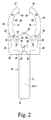
- FIG. 1 is a perspective view of one embodiment of a patella resection assembly incorporating the principles of the present invention
- FIG. 2 is a top plan view of the patella resection assembly of FIG. 1 , illustrating the assembly in a first, open position;
- FIG. 3 is a top plan view of the patella resection assembly of FIGS. 1-2 , illustrating the assembly in a second, closed position;
- FIG. 4 is a side elevation of the patella resection assembly of FIGS. 1-3 in the first, open position;
- FIG. 5 is a top plan view of the handle of the patella resection assembly of FIGS. 1-4 ;
- FIG. 6 is a top plan view of an alternative handle
- FIG. 7 is a top plan view of a second embodiment of a patella resection assembly embodying the principles of the present invention, utilizing the handle of FIG. 6 and illustrating the patella resection assembly in a first, open position;
- FIG. 8 is a top plan view of the patella resection assembly of FIG. 7 , illustrating the patella resection assembly in a second, closed position.
- anatomical references such as anterior, posterior, medial, lateral, superior, inferior, etcetera
- terms representing anatomical references may be used throughout the specification in reference to the orthopaedic implants and surgical instruments described herein as well as in reference to the patient's natural anatomy.
- Such terms have well-understood meanings in both the study of anatomy and the field of orthopaedics. Use of such anatomical reference terms in the written description and claims is intended to be consistent with their well-understood meanings unless noted otherwise.
- proximal and distal in reference to the illustrated patella resection assemblies are in relation to the user of the instruments. Thus, proximal refers to a location nearer to the user and distal refers to a location further from the user.
- the illustrated patella resection assembly 10 comprises a handle 12, a slide member 20 and two claw members 40, 52.
- the handle 12 has a proximal end 14, a distal end 16, and a longitudinal axis 18.
- the longitudinal axis 18 lays in a longitudinal plane 17 dividing the assembly 10 into medial and lateral halves.
- the slide member 20 includes a first bone-gripping member 24, a base 26, a first outer arm 28 and a second outer arm 30.
- the first arm 28 extends distally from the base 26 to a free distal end 32 and the second arm 30 extends distally from the base 26 to a free distal end 34.
- the slide member 20 also includes a middle arm 35 extending distally from the base 26 along the longitudinal plane 17.
- the first illustrated slide member 20 also includes a tab 27 extending upwardly from the base 26.
- the slide member 20 is selectively movable with respect to the handle 12 in a linear direction along the longitudinal axis 18 of the handle between a first position shown in FIG. 2 and a second position shown in FIG. 3 . In the second position of FIG. 3 , the slide 20 is more distal than in the first position of FIG. 1 .
- the first claw member 40 extends from the distal end 16 of the handle 12 along one side of the longitudinal plane 17 to a first free distal end 42.
- the first claw member 40 has a flat and planar surface 44 for guiding a saw blade (not shown), a second bone-gripping member 46 at the first free end 42, a curved outer edge 48 and a second end 50 mounted to the handle 12.
- the second claw member 52 extends from the distal end 16 of the handle 12 along the side of the longitudinal plane 17 opposite from the first claw member 40 to a second free distal end 54.
- the second claw member 52 has a flat and planar surface 56 co-planar with the flat and planar surface 44 of the first claw member 40, a third bone-gripping member 58 at the second free distal end 54, a curved outer edge 60 and a second end 62 mounted to the handle 12.
- first free end 42 of the first claw member 40 and the second free end 54 of the second claw member 52 are spaced distally from the distal end 16 of the handle 12.
- the first claw member 40, second claw member 52 and first bone-gripping member 24 define an opening 64 between them to receive a patella.
- the illustrated embodiment also includes fourth and fifth bone-gripping members 47, 59 extending into the opening 64 from the inner edges of the claw members 40, 52 along the most medial and most lateral portions of the inner edges.
- All of the bone-gripping members 24, 46, 47, 58, 59 in the illustrated embodiment comprise one or more pointed or sharp teeth facing into the opening 64.
- All of the teeth of the bone-gripping members 24, 46, 47, 58, 59 lie in a plane that is perpendicular to the longitudinal plane 17. The teeth are positioned and oriented so that when the patella is received between and engaged by the teeth, a plurality of points on the patella are engaged (such as three spaced points) so that the patella is held with no relative movement between the patella and the patella resection guide.
- All of the bone-gripping members 24, 46, 47, 58, 59 may be formed integrally with their respective parts or formed as separate elements fixed to their respective parts.
- the inner edges 36, 38 of the side arms 28, 30 of the slide member 20 contact the curved outer edges 48, 60 of the claw members 40, 52 when the slide member 20 is in the first position of FIG. 2 and when the slide member 20 is in the second position of FIG. 3 .
- the curved outer edges 48, 60 of the claw members 40, 52 are substantially elliptical in shape, curving outwardly from their second ends 50, 62 to their widest points and then curving back inwardly toward the distal ends 42, 54.
- the inner edges of the claw members are similarly shaped.
- the inner edges 36, 38 of the side arms 28, 30 are substantially straight, and diverge outwardly from the base 26 in the distal direction.
- the space between the inner edges 36, 38 is greatest at the free distal ends 32, 34 and least at the junctions of the side arms 28, 30 with the base 26.
- the contacts between the diverging inner edges 36, 38 of the side arms 28, 30 and curved outer edges 48, 60 of the claw members 40, 52 change, so that the contacts are at more proximal portions of the inner edges 36, 38 of the side arms 28, 30 where the space between the inner edges 36, 38 is more narrow.
- distal movement of the slide member 20 forces the claw members 40, 52 to move towards each other and causes the gap between all of the bone-gripping members 24, 46, 58 to decrease until the bone-gripping members contact the periphery of a patella positioned in the opening 64.
- the first illustrated embodiment uses a pivotal connection between the claw members 40, 52 and the handle 12.
- This pivotal connection may comprise pins, such as those shown at 70, 72 in FIGS. 1-3 received in cylindrical holes.
- the pins 70, 72 extend upward from shoulders 74, 76 extending outwardly from the distal end 16 of the handle 12 and the cylindrical holes are formed in the proximal ends 50, 62 of the claw members 40, 52.
- this pin and hole arrangement is provided as an example of a possible pivot connection that may be used with the first embodiment; other types of pivot connections that allow the claw members to pivot could be employed and the invention is not limited to the illustrated pivot connection mechanism unless expressly called for in the claims.
- the first illustrated embodiment uses a sliding connection comprising pair of pins and a pair of elongate slots extending in the proximal-distal direction.
- the pins 78, 80 and slots 82, 84 are shown in phantom.
- the pins 78, 80 in the first illustrated embodiment are fixed to and extend upright from the handle 12, and the slots 82, 84 are formed in the slide member 20.
- the assembly may include structures to prevent the slide member from lifting off of the handle 12.
- the sliding connection could comprise an elongate dovetail connection.
- FIGS. 7-8 at 10A An alternative embodiment of a patella resection assembly is shown in FIGS. 7-8 at 10A.
- parts similar to those described above for the first embodiment are shown with reference numbers corresponding to those used for the first embodiment, followed by the letter "A".
- elongate slots 82A, 84A are formed in the handle 12 instead of the slide member, and pins 78A, 80A extend downward from the slide member 20A to mount the slide member 20A to the handle 12A through a sliding connection.
- the shoulders 74A, 76A of the handle 12A of the second illustrated patella resection assembly 10A are also shaped differently from the shoulders 74, 76 of the first illustrated patella resection assembly 10. Sliding movement of the slide member 20A is substantially the same as sliding movement of the slide member 20. Structures to prevent the slide member 20A from lifting off of the handle 12A may also be included.
- the second embodiment provides a linear movement connection comprising pins and slots.
- pins 92, 93, 94, 95 extend upwardly from the shoulders or flanges 74A, 76A of the handle 12A and are received in elongate slots 96, 97 in the claw members 40A, 52A.
- Two pins 92, 93 are linearly aligned and fixed to the shoulder or flange 74A of the handle 12A.
- Two pins 94, 95 are linearly aligned with each other and with the first two pins 92, 93 and are fixed to the shoulder or flange 76A of the handle 12A.
- the elongate slots 96, 97 are linearly aligned with each other and are formed in the second ends 50A, 62A of the claw members 40A, 52A.
- the slots 96, 97 are perpendicular to the longitudinal axis 18A of the handle.
- distal movement of the slide member 20A forces the claw members 40A, 52A to move towards each other and causes the gap between all of the bone-gripping members 24A, 46A, 58A to decrease until the bone-gripping members contact the periphery of a patella positioned in the opening 64A.
- distal movement of the slide member 20A pushes the claw members 40A, 52A toward the longitudinal plane 17A to close the opening around the patella.
- Additional features may be incorporated into either of the illustrated embodiments.
- springs or the like may be provided to bias the claw members 40, 40A, 52, 52A to the positions shown in FIGS. 1 , 2 and 7 .
- additional flat members may be provided overlying and parallel to the surfaces 44, 44A, 56, 56A to define co-planar slots to receive the saw blade used in resecting the patella.
- the handle 12, 12A and slide member 20, 20A may also include a variety of structures to lock the slide member 20, 20A in preselected positions.
- a releasable linear ratchet and pawl mechanism could be employed.
- a stylus could also be assembled with either illustrated patella resection assembly 10, 10A to aid in setting resection level for the patella.
- the surgeon would make a standard incision and then partially or fully evert the patient's patella to expose the posterior side of the patella.
- the slide member 20, 20A retracted proximally to the positions shown in FIGS. 1 , 2 and 7 , the claw members 40, 52, 40A, 52A may be introduced to the surgical site and moved across the patella until the patella is received in the opening 64, 64A.
- the surgeon may then push on the tab 27, 27A to slide the slide member distally until the bone-gripping members 24, 46, 47, 58, 59, 24A, 46A, 47A, 58A, 59A, contact the periphery of the patella.
- the surgeon may then continue to push the tab 27, 27A to slide the slide member distally until the bone-gripping members 24, 46, 47, 58, 59, 24A, 46A, 47A, 58A, 59A, fully engage and grip the periphery of the patella.
- a variety of sizes of patellae may be clamped through multiple spaced contact points and be held while the co-planar surfaces 44, 56, 44A, 56A (along with the upper surface of the slide member) define the resection level.
- the surgeon may place the flat edge of the surgical saw blade along one of the flat, co-planar guide surfaces 44, 56, 44A, 56A and guide the saw blade across the patella until the saw blade rests on an opposite guide surface.
- the design of the illustrated patella resection assembly 10, 10A allows for selection of the most appropriate and economical material to be used to make the constituent elements.
- the handle 12 could be made of metal, plastic or other material; the handle 12 may be made relatively inexpensively by injection molding of suitable polymers.
- the claw members 40, 40A, 52, 52A could also be made of metal, plastic or other material, although it may be preferred to construct the claw member such that at least surfaces 44, 44A and 56, 56A are metal so that appropriate support is provided for the saw blade.
- processes such as those described in U.S. Patent Publication No.
- 2010168753A1 entitled “Orthopaedic Cutting Block Having a Chemically Etched Metal Insert and Method of Manufacturing," the complete disclosure of which is incorporated by reference herein, may be used to make a combination polymermetal claw member 40, 40A, 52, 52A. Standard metals and polymers for instruments may be used.
Abstract
Description
- The present disclosure relates generally to orthopaedic surgical instruments and more particularly to patella resectioning guides.
- Joint arthroplasty is a well-known surgical procedure by which a diseased and/or damaged natural joint is replaced by a prosthetic joint. A typical knee prosthesis includes a tibial tray, a femoral component, and a polymer insert or bearing positioned between the tibial tray and the femoral component. In some cases, the knee prosthesis may also include a prosthetic patella component, which is secured to a posterior side of the patient's surgically-prepared patella. To prepare the patella, an orthopaedic surgeon first resects the posterior dome side of the patient's natural patella to secure the prosthetic component thereto. In use, the patella component articulates with the patient's natural or prosthetic femur during extension and flexion of the patient's knee.
- To facilitate the replacement of the natural joint with the knee prosthesis, orthopaedic surgeons use a variety of orthopaedic surgical instruments such as, for example, cutting blocks, drill guides, milling guides, and other surgical instruments. Typically, the orthopaedic surgical instruments are generic with respect to the patient such that the same orthopaedic surgical instrument may be used on a number of different patients during similar orthopaedic surgical procedures.
- In resecting the patella, surgeons frequently perform the resection free-hand. However, free-hand cutting the patella is not as accurate as a guided resection. Moreover, it is important that a sufficient amount of bone stock remain after resection to accept the fixation means for the patellar prosthesis and to maintain the integrity of the remaining patella. To ensure that the patella implant is properly positioned and that an appropriate amount of bone remains after resection, a resection guide is needed.
- Depending on a number of factors, including the size of the patient, native patellae are of substantially different sizes. Accordingly, if a resection guide is to be used, either the guide must be provided in a plurality of sizes to accommodate variations in patellae size or an adjustable resection guide must be used.
- The present invention provides an adjustable patella resection guide that assists the surgeon in performing a resection while the patella is gripped securely.
- In illustrative embodiments, the present invention provides a patella resection assembly comprising a handle, a slide member and first and second claw members. The handle has a proximal end, a distal end, and a longitudinal axis between the proximal end and distal end defining a longitudinal plane. The slide member is movably mounted on the handle and includes a first bone-gripping member, a base, a first arm and a second arm. The first arm and the second arm extend from the base in a distal direction to free distal ends. The first arm is positioned on one side of the longitudinal plane and the second arm is positioned on the opposite side of the longitudinal plane. The first arm has an inner edge facing the longitudinal plane and the second arm has an inner edge facing the longitudinal plane; the inner edges diverge in the distal direction. The slide member is selectively movable in a linear direction along the longitudinal axis of the handle toward and away from the proximal end and distal end of the handle between a first position and a second position. The second position is more distal than the first position. The first claw member extends from the distal end of the handle to a free end. The first claw member is positioned on one side of the longitudinal plane, and has a flat and planar surface for guiding a saw blade, a second bone-gripping member at the first free end, a curved outer edge and a second end mounted to the handle. The second claw member extends from the distal end of the handle to a free end. The second claw member is positioned on the side of the longitudinal plane opposite the position of the first claw member, and has a flat and planar surface co-planar with the flat and planar surface of the first claw member, a third gripping member at the free end, a curved outer edge and a second end mounted to the handle. The free end of the first claw member and the free end of the second claw member are spaced distally from the distal end of the handle. The first bone-gripping member, first claw member and the second claw member define an opening between them to receive a patella. The inner edge of the first arm of the slide member and the outer edge of the first claw member contact each other, and the inner edge of the second arm of the slide member and the outer edge of the second claw member contact each other. Longitudinal movement of the slide member from the first position to the second position causes the first bone-gripping member to move distally and the free ends of the first claw member and the second claw member to move toward each other. The opening defined by the first bone-gripping member, first claw member and the second claw member has one size when the slide member is in the first position and a smaller size when the slide member is in the second position.
- In a more particular embodiment, a fourth gripping member extends from the first claw member toward the opening at a position spaced from the free end of the first claw member and a fifth gripping member extends from the second claw member toward the opening at a position spaced from the free end of the second claw member.
- In another more particular embodiment, the first and second claw members are pivotally connected to the handle and longitudinal movement of the slide member from the first position to the second position causes the first claw member and the second claw member to pivot.
- In another alternative embodiment, the first and second claw members are connected to the handle by linear movement connectors so that longitudinal movement of the slide member from the first position to the second position causes the first claw member and the second claw member to move linearly toward each other.
- In another more particular embodiment, the slide member includes a middle arm extending from the base along the longitudinal axis of the handle to a distal end and the first bone-gripping member is at the distal end of the middle arm.
- The detailed description particularly refers to the following figures, in which:
-
FIG. 1 is a perspective view of one embodiment of a patella resection assembly incorporating the principles of the present invention; -
FIG. 2 is a top plan view of the patella resection assembly ofFIG. 1 , illustrating the assembly in a first, open position; -
FIG. 3 is a top plan view of the patella resection assembly ofFIGS. 1-2 , illustrating the assembly in a second, closed position; -
FIG. 4 is a side elevation of the patella resection assembly ofFIGS. 1-3 in the first, open position; -
FIG. 5 is a top plan view of the handle of the patella resection assembly ofFIGS. 1-4 ; -
FIG. 6 is a top plan view of an alternative handle; -
FIG. 7 is a top plan view of a second embodiment of a patella resection assembly embodying the principles of the present invention, utilizing the handle ofFIG. 6 and illustrating the patella resection assembly in a first, open position; and -
FIG. 8 is a top plan view of the patella resection assembly ofFIG. 7 , illustrating the patella resection assembly in a second, closed position. - While the concepts of the present disclosure are susceptible to various modifications and alternative forms, specific exemplary embodiments thereof have been shown by way of example in the drawings and will herein be described in detail. It should be understood, however, that there is no intent to limit the concepts of the present disclosure to the particular forms disclosed, but on the contrary, the intention is to cover all modifications, equivalents, and alternatives falling within the spirit and scope of the invention as defined by the appended claims.
- Terms representing anatomical references, such as anterior, posterior, medial, lateral, superior, inferior, etcetera, may be used throughout the specification in reference to the orthopaedic implants and surgical instruments described herein as well as in reference to the patient's natural anatomy. Such terms have well-understood meanings in both the study of anatomy and the field of orthopaedics. Use of such anatomical reference terms in the written description and claims is intended to be consistent with their well-understood meanings unless noted otherwise.
- References to "proximal" and "distal" in reference to the illustrated patella resection assemblies are in relation to the user of the instruments. Thus, proximal refers to a location nearer to the user and distal refers to a location further from the user.
- Referring to
FIG. 1 , a first embodiment of apatella resection assembly 10 is illustrated. The illustratedpatella resection assembly 10 comprises ahandle 12, aslide member 20 and twoclaw members - The
handle 12 has aproximal end 14, adistal end 16, and a longitudinal axis 18. The longitudinal axis 18 lays in a longitudinal plane 17 dividing theassembly 10 into medial and lateral halves. - The
slide member 20 includes a first bone-gripping member 24, abase 26, a firstouter arm 28 and a secondouter arm 30. Thefirst arm 28 extends distally from thebase 26 to a freedistal end 32 and thesecond arm 30 extends distally from thebase 26 to a freedistal end 34. Theslide member 20 also includes a middle arm 35 extending distally from thebase 26 along the longitudinal plane 17. The first illustratedslide member 20 also includes atab 27 extending upwardly from thebase 26. - The
slide member 20 is selectively movable with respect to thehandle 12 in a linear direction along the longitudinal axis 18 of the handle between a first position shown inFIG. 2 and a second position shown inFIG. 3 . In the second position ofFIG. 3 , theslide 20 is more distal than in the first position ofFIG. 1 . - The
first claw member 40 extends from thedistal end 16 of thehandle 12 along one side of the longitudinal plane 17 to a first freedistal end 42. Thefirst claw member 40 has a flat andplanar surface 44 for guiding a saw blade (not shown), a second bone-grippingmember 46 at the firstfree end 42, a curvedouter edge 48 and asecond end 50 mounted to thehandle 12. - The
second claw member 52 extends from thedistal end 16 of thehandle 12 along the side of the longitudinal plane 17 opposite from thefirst claw member 40 to a second freedistal end 54. Thesecond claw member 52 has a flat andplanar surface 56 co-planar with the flat andplanar surface 44 of thefirst claw member 40, a third bone-grippingmember 58 at the second freedistal end 54, a curvedouter edge 60 and asecond end 62 mounted to thehandle 12. - As illustrated in
FIGS. 1-3 , the firstfree end 42 of thefirst claw member 40 and the secondfree end 54 of thesecond claw member 52 are spaced distally from thedistal end 16 of thehandle 12. Thefirst claw member 40,second claw member 52 and first bone-grippingmember 24 define anopening 64 between them to receive a patella. The illustrated embodiment also includes fourth and fifth bone-grippingmembers claw members - All of the bone-gripping
members opening 64. All of the teeth of the bone-grippingmembers members - In the
assembly 10, theinner edges side arms slide member 20 contact the curvedouter edges claw members slide member 20 is in the first position ofFIG. 2 and when theslide member 20 is in the second position ofFIG. 3 . As can be seen fromFIGS. 1-3 , the curvedouter edges claw members - As shown in
FIGS. 1-3 , theinner edges side arms inner edges side arms base 26. As can be seen inFIGS. 2 and3 , as theslide member 20 is moved distally from the position shown inFIG. 2 to the position shown inFIG. 3 , the contacts between the diverginginner edges side arms outer edges claw members inner edges side arms inner edges slide member 20 forces theclaw members members opening 64. - To allow for such movement of the
claw members claw members handle 12. This pivotal connection may comprise pins, such as those shown at 70, 72 inFIGS. 1-3 received in cylindrical holes. In the illustrated embodiment, thepins shoulders distal end 16 of thehandle 12 and the cylindrical holes are formed in the proximal ends 50, 62 of theclaw members - To allow for proximal-distal movement of the
slide member 20, the first illustrated embodiment uses a sliding connection comprising pair of pins and a pair of elongate slots extending in the proximal-distal direction. InFIGS. 1-3 , thepins slots FIGS. 4-5 , thepins handle 12, and theslots slide member 20. It should be understood that the assembly may include structures to prevent the slide member from lifting off of thehandle 12. Alternatively, the sliding connection could comprise an elongate dovetail connection. - An alternative embodiment of a patella resection assembly is shown in
FIGS. 7-8 at 10A. In this embodiment, parts similar to those described above for the first embodiment are shown with reference numbers corresponding to those used for the first embodiment, followed by the letter "A". In the second illustrated embodiment,elongate slots handle 12 instead of the slide member, and pins 78A, 80A extend downward from theslide member 20A to mount theslide member 20A to thehandle 12A through a sliding connection. Theshoulders handle 12A of the second illustratedpatella resection assembly 10A are also shaped differently from theshoulders patella resection assembly 10. Sliding movement of theslide member 20A is substantially the same as sliding movement of theslide member 20. Structures to prevent theslide member 20A from lifting off of thehandle 12A may also be included. - In the second illustrated
patella resection assembly 10A, movement of theclaw members slide member 20A is linear rather than pivotal. To accomplish this linear movement, the second embodiment provides a linear movement connection comprising pins and slots. In this embodiment, pins 92, 93, 94, 95 extend upwardly from the shoulders orflanges handle 12A and are received inelongate slots claw members pins flange 74A of thehandle 12A. Twopins pins flange 76A of thehandle 12A. Theelongate slots claw members slots longitudinal axis 18A of the handle. - As shown in
FIGS. 7-8 , as theslide member 20A is moved distally from the position shown inFIG. 7 to the position shown inFIG. 8 , the contacts between the diverginginner edges side arms outer edges claw members inner edges side arms inner edges slide member 20A forces theclaw members members opening 64A. In the second illustrated embodiment, distal movement of theslide member 20A pushes theclaw members longitudinal plane 17A to close the opening around the patella. - Additional features may be incorporated into either of the illustrated embodiments. For example, springs or the like may be provided to bias the
claw members FIGS. 1 ,2 and7 . Moreover, additional flat members may be provided overlying and parallel to thesurfaces handle slide member slide member patella resection assembly - To use the
patella resection assembly slide member FIGS. 1 ,2 and7 , theclaw members opening tab members tab members co-planar surfaces - It will be appreciated that the design of the illustrated
patella resection assembly handle 12 could be made of metal, plastic or other material; thehandle 12 may be made relatively inexpensively by injection molding of suitable polymers. Theclaw members U.S. Patent Publication No. 2010168753A1 , entitled "Orthopaedic Cutting Block Having a Chemically Etched Metal Insert and Method of Manufacturing," the complete disclosure of which is incorporated by reference herein, may be used to make a combinationpolymermetal claw member - While the disclosure has been illustrated and described in detail in the drawings and foregoing description, such an illustration and description is to be considered as exemplary and not restrictive in character, it being understood that only illustrative embodiments have been shown and described and that all changes and modifications that come within the spirit of the disclosure are desired to be protected.
- There are a plurality of advantages of the present disclosure arising from the various features of the method, apparatus, and system described herein. It will be noted that alternative embodiments of the method, apparatus, and system of the present disclosure may not include all of the features described yet still benefit from at least some of the advantages of such features. Those of ordinary skill in the art may readily devise their own implementations of the method, apparatus, and system that incorporate one or more of the features of the present invention and fall within the spirit and scope of the present disclosure as defined by the appended claims.
Claims (6)
- A patella resection assembly comprising:a handle having a proximal end, a distal end, and a longitudinal axis between the proximal end and distal end defining a longitudinal plane;a slide member movably mounted on the handle and including a first bone-gripping member, a base, a first arm and a second arm, the first arm and the second arm extending from the base in a distal direction to free distal ends, the first arm being positioned on one side of the longitudinal plane and the second arm being positioned on the opposite side of the longitudinal plane, the first arm having an inner edge facing the longitudinal plane and the second arm having an inner edge facing the longitudinal plane, the inner edges diverging in the distal direction;the slide member being selectively movable in a linear direction along the longitudinal axis of the handle toward and away from the proximal end and distal end of the handle between a first position and a second position, the second position being more distal than the first position;a first claw member extending from the distal end of the handle to a free end, the first claw member being positioned on one side of the longitudinal plane, the first claw member having a flat and planar surface for guiding a saw blade, a second gripping member at the first free end, a curved outer edge and a second end mounted to the handle;a second claw member extending from the distal end of the handle to a free end, the second claw member being positioned on the side of the longitudinal plane opposite the position of the first claw member, the second claw member having a flat and planar surface co-planar with the flat and planar surface of the first claw member, a third gripping member at the free end, a curved outer edge and a second end mounted to the handle;the free end of the first claw member and the free end of the second claw member being spaced distally from the distal end of the handle;the first bone-gripping member, first claw member and the second claw member defining an opening between them to receive a patella;wherein:the inner edge of the first arm of the slide member contacts the outer edge of the first claw member and the inner edge of the second arm of the slide member contacts the outer edge of the second claw member;longitudinal movement of the slide member from the first position to the second position causes the first bone-gripping member to move distally and the free ends of the first claw member and the second claw member to move toward each other; andthe opening defined by the first bone-gripping member, first claw member and the second claw member has one size when the slide member is in the first position and a smaller size when the slide member is in the second position.
- The patella resection assembly of claim 1 further comprising:a fourth gripping member extending from the first claw member toward the opening at a position spaced from the free end of the first claw member; anda fifth gripping member extending from the second claw member toward the opening at a position spaced from the free end of the second claw member.
- The patella resection assembly of claim 1 wherein:
the first claw member is pivotally connected to the handle;the second claw member is pivotally connected to the handle; andlongitudinal movement of the slide member from the first position to the second position causes the first claw member and the second claw member to pivot. - The patella resection assembly of claim 1 wherein the first claw member and second claw member are connected to the handle by linear movement connections so that longitudinal movement of the slide member from the first position to the second position causes the first claw member and the second claw member to move linearly toward each other.
- The patella resection assembly of claim 4 wherein the linear movement connections comprise pins and slots.
- The patella resection assembly of claim 1 wherein:the slide member includes a middle arm extending from the base along the longitudinal axis of the handle to a distal end; andthe first bone-gripping member is at the distal end of the middle arm.
Applications Claiming Priority (2)
| Application Number | Priority Date | Filing Date | Title |
|---|---|---|---|
| US201161540061P | 2011-09-28 | 2011-09-28 | |
| US13/548,676 US8998913B2 (en) | 2011-09-28 | 2012-07-13 | Patella resection assembly |
Publications (2)
| Publication Number | Publication Date |
|---|---|
| EP2574291A1 true EP2574291A1 (en) | 2013-04-03 |
| EP2574291B1 EP2574291B1 (en) | 2014-03-19 |
Family
ID=47008375
Family Applications (1)
| Application Number | Title | Priority Date | Filing Date |
|---|---|---|---|
| EP12186730.3A Active EP2574291B1 (en) | 2011-09-28 | 2012-09-28 | Patella resection assembly |
Country Status (3)
| Country | Link |
|---|---|
| US (1) | US8998913B2 (en) |
| EP (1) | EP2574291B1 (en) |
| JP (1) | JP6005463B2 (en) |
Families Citing this family (2)
| Publication number | Priority date | Publication date | Assignee | Title |
|---|---|---|---|---|
| US11642138B2 (en) * | 2020-06-05 | 2023-05-09 | Smith & Nephew, Inc. | Patella clamp |
| US11723677B2 (en) | 2020-10-16 | 2023-08-15 | Howmedica Osteonics Corp. | Patella resection guide with independent adjustment |
Citations (5)
| Publication number | Priority date | Publication date | Assignee | Title |
|---|---|---|---|---|
| US20030163137A1 (en) * | 2002-02-26 | 2003-08-28 | Smucker Donald M. | Patella resection guide |
| US20040153066A1 (en) * | 2003-02-03 | 2004-08-05 | Coon Thomas M. | Apparatus for knee surgery and method of use |
| EP1723916A1 (en) * | 2005-05-18 | 2006-11-22 | Depuy International Limited | Patellar resection tool |
| US7566335B1 (en) * | 2004-11-22 | 2009-07-28 | Biomet Manufacturing Corp. | Method and apparatus for patella resection |
| US20100168753A1 (en) | 2008-12-29 | 2010-07-01 | Edwards Jon M | Orthopaedic cutting block having a chemically etched metal insert and method of manufacturing |
Family Cites Families (88)
| Publication number | Priority date | Publication date | Assignee | Title |
|---|---|---|---|---|
| US2181746A (en) | 1939-02-04 | 1939-11-28 | John R Siebrandt | Combination bone clamp and adjustable drill guide |
| US3835849A (en) | 1973-01-26 | 1974-09-17 | Guire G Mc | Bone clamp and adjustable drill guide |
| JPS5153667Y2 (en) * | 1973-07-31 | 1976-12-22 | ||
| USD260927S (en) | 1979-03-14 | 1981-09-22 | Glenn Edward C | Dowell pin positioner |
| USD281622S (en) | 1983-08-29 | 1985-12-03 | Diamond Michael K | Combined dental mirror and moisture control apparatus |
| US4565192A (en) | 1984-04-12 | 1986-01-21 | Shapiro James A | Device for cutting a patella and method therefor |
| US4633862A (en) | 1985-05-30 | 1987-01-06 | Petersen Thomas D | Patellar resection sawguide |
| US5002547A (en) | 1987-02-07 | 1991-03-26 | Pfizer Hospital Products Group, Inc. | Apparatus for knee prosthesis |
| US5116338A (en) | 1988-02-03 | 1992-05-26 | Pfizer Hospital Products Group, Inc. | Apparatus for knee prosthesis |
| US5250050A (en) | 1987-02-07 | 1993-10-05 | Pfizer Hospital Products Group, Inc. | Apparatus for knee prosthesis |
| US5382254A (en) | 1989-07-18 | 1995-01-17 | United States Surgical Corporation | Actuating handle for surgical instruments |
| US5129908A (en) | 1990-01-23 | 1992-07-14 | Petersen Thomas D | Method and instruments for resection of the patella |
| US5021055A (en) | 1990-09-19 | 1991-06-04 | Intermedics Orthopedics, Inc. | Patellar clamp and surgical saw guide |
| US5129907A (en) | 1990-12-10 | 1992-07-14 | Zimmer, Inc. | Patellar clamp and reamer with adjustable stop |
| US5180384A (en) | 1991-02-08 | 1993-01-19 | Mikhail Michael W E | Method for implanting a patellar prosthesis |
| US5222955A (en) | 1991-02-08 | 1993-06-29 | Mikhail Michael W E | Method for implanting a patellar prosthesis |
| US5108401A (en) | 1991-04-12 | 1992-04-28 | New York Society For The Relief Of The Ruptured And Crippled, Maintaining The Hospital For Special Surgery | Patella cutting clamp |
| US5147365A (en) | 1991-08-19 | 1992-09-15 | Intermedics Orthopedics, Inc. | Patellar osteotomy guide |
| US5484451A (en) | 1992-05-08 | 1996-01-16 | Ethicon, Inc. | Endoscopic surgical instrument and staples for applying purse string sutures |
| US5284485A (en) | 1992-09-16 | 1994-02-08 | Ethicon, Inc. | Endoscopic knotting device |
| US5415663A (en) | 1993-12-02 | 1995-05-16 | Johnson & Johnson Orthopaedics, Inc. | Orthopaedic cutting guides with retractable saw blade slots |
| US6074425A (en) | 1994-01-14 | 2000-06-13 | Biomedical Engineering Trust I | Fixed bearing joint endoprosthesis |
| US5536271A (en) | 1994-06-02 | 1996-07-16 | Depuy, Inc. | Patella reaming system |
| USD367531S (en) | 1994-06-27 | 1996-02-27 | Zimmer, Inc. | External fixation clamp |
| US5470328A (en) | 1994-07-21 | 1995-11-28 | Snowden-Pencer, Inc. | Surgical instrument handle and actuator means |
| US5810827A (en) | 1994-09-02 | 1998-09-22 | Hudson Surgical Design, Inc. | Method and apparatus for bony material removal |
| US5611802A (en) | 1995-02-14 | 1997-03-18 | Samuelson; Kent M. | Method and apparatus for resecting bone |
| US5575793A (en) | 1995-02-15 | 1996-11-19 | Smith & Nephew Richards Inc. | Patella clamp apparatus |
| US5593450A (en) | 1995-02-27 | 1997-01-14 | Johnson & Johnson Professional, Inc. | Oval domed shaped patella prosthesis |
| US5520692A (en) | 1995-02-28 | 1996-05-28 | Wright Medical Technology, Inc. | Adjustable depth patella recessing guide and method |
| US5626607A (en) | 1995-04-03 | 1997-05-06 | Heartport, Inc. | Clamp assembly and method of use |
| US5542947A (en) * | 1995-05-12 | 1996-08-06 | Huwmedica Inc. | Slotted patella resection guide and stylus |
| US5968051A (en) | 1995-07-27 | 1999-10-19 | Johnson & Johnson Professional, Inc. | Patella clamping device |
| US5582615A (en) | 1995-10-30 | 1996-12-10 | Pilling Weck, Incorporated | Handle for surgical clip applicator systems |
| USD373635S (en) | 1995-11-14 | 1996-09-10 | Zimmer, Inc. | External fixation clamp |
| US5716362A (en) | 1996-02-20 | 1998-02-10 | Howmedica Inc. | Patella milling instrument |
| US5667512A (en) | 1996-05-03 | 1997-09-16 | Metagen, Llc | Patellar resection guide |
| US5827279A (en) | 1996-12-06 | 1998-10-27 | Ethicon Endo-Surgery, Inc. | Knife coupler mechanism for an endoscopic instrument |
| US8083745B2 (en) | 2001-05-25 | 2011-12-27 | Conformis, Inc. | Surgical tools for arthroplasty |
| GB9804281D0 (en) | 1998-02-27 | 1998-04-22 | Johnson & Johnson Medical Ltd | Handle assembly |
| AU3084499A (en) | 1998-03-13 | 1999-09-27 | Theodore I. Macey | Method and apparatus for clamping |
| US5944723A (en) | 1998-03-27 | 1999-08-31 | Johnson & Johnson Professional, Inc. | Locking orthopaedic clamping tool |
| US6010509A (en) | 1998-07-01 | 2000-01-04 | The Dana Center For Orthopaedic Implants | Patella resection drill and prosthesis implantation device |
| US6080162A (en) | 1998-09-28 | 2000-06-27 | Depuy Orthopaedics, Inc. | Modular orthopaedic clamping tool |
| US5941884A (en) | 1998-10-09 | 1999-08-24 | Osteonics Corp. | Patella preparation apparatus and method |
| US6074343A (en) * | 1999-04-16 | 2000-06-13 | Nathanson; Michael | Surgical tissue retractor |
| US6419675B1 (en) | 1999-09-03 | 2002-07-16 | Conmed Corporation | Electrosurgical coagulating and cutting instrument |
| US6190391B1 (en) | 1999-10-01 | 2001-02-20 | Bristol-Myers Squibb Company | Method of preparing a resected posterior surface of a patella to receive a prosthetic element |
| US20020115987A1 (en) | 2001-02-16 | 2002-08-22 | Path | Needle cannula removal by extraction |
| US6551316B1 (en) | 2001-03-02 | 2003-04-22 | Beere Precision Medical Instruments, Inc. | Selective compression and distraction instrument |
| USD463550S1 (en) | 2001-03-27 | 2002-09-24 | Thomas Sherman | Eyedropper positioning device |
| USD459474S1 (en) | 2001-06-19 | 2002-06-25 | Impra, Inc. | Stent delivery apparatus |
| US6855150B1 (en) | 2001-07-13 | 2005-02-15 | Timothy R. Linehan | Patellar trial and drill guide for use in knee replacement surgery |
| US6866667B2 (en) | 2002-09-03 | 2005-03-15 | Symmetry Medical, Inc. | Patellar milling clamp |
| US7946982B2 (en) * | 2002-10-25 | 2011-05-24 | K2M, Inc. | Minimal incision maximal access MIS spine instrumentation and method |
| US20040162561A1 (en) | 2003-02-13 | 2004-08-19 | Howmedica Osteonics Corp. | Modular patella instrument |
| GB2401550B (en) | 2003-05-12 | 2005-04-20 | Corin Ltd | Head centering jig for femoral resurfacing |
| US20050240196A1 (en) | 2004-03-09 | 2005-10-27 | Davis Kenneth P | Apparatus for use in orthopaedic surgery |
| US7686533B2 (en) | 2004-10-22 | 2010-03-30 | Howmedia Osteonics Corp. | Universal coupler |
| JP3995681B2 (en) * | 2004-11-11 | 2007-10-24 | 哲 渡邉 | Patella cutting instrument |
| US7632279B2 (en) | 2004-12-27 | 2009-12-15 | Howmedica Osteonics Corp. | Patella resection clamp |
| US8021366B2 (en) | 2005-07-11 | 2011-09-20 | Kyphon Sarl | Axial load limiting system and methods |
| EP1931264A1 (en) | 2005-10-07 | 2008-06-18 | Alphatec Spine, Inc. | Retractor and methods of use |
| GB0526385D0 (en) | 2005-12-28 | 2006-02-08 | Mcminn Derek J W | Improvements in or relating to knee prosthesis |
| US8182488B2 (en) | 2006-03-14 | 2012-05-22 | Ralph Scott Oliver | Apparatus and method for implementing patella resection guide during minimally invasive surgery |
| GB0607027D0 (en) | 2006-04-07 | 2006-05-17 | Depuy Int Ltd | Patella tracking |
| USD549331S1 (en) | 2006-09-13 | 2007-08-21 | Senko Medical Instrument Mfg., Co. | Patella trap retractor for knee arthroplasty |
| US20080097450A1 (en) | 2006-09-14 | 2008-04-24 | Zimmer Technology, Inc. | Patella clamp |
| ES2337712T3 (en) | 2006-10-12 | 2010-04-28 | WALDEMAR LINK GMBH & CO. KG | MODULAR ROTULAR INSTRUMENTAL. |
| US7758651B2 (en) | 2006-10-18 | 2010-07-20 | Howmedica Osteonics Corp. | Mis patellar preparation |
| US8147497B2 (en) | 2007-03-02 | 2012-04-03 | Greatbatch Medical S.A. | In situ patellar fixing system |
| WO2008112996A1 (en) | 2007-03-14 | 2008-09-18 | Conformis, Inc. | Surgical tools for arthroplasty |
| US8092544B2 (en) | 2008-06-30 | 2012-01-10 | Depuy Products, Inc. | Implantable patella component having a thickened superior edge |
| US7972383B2 (en) | 2008-06-30 | 2011-07-05 | Depuy Products, Inc. | Implantable patella component having a thickened superior edge |
| USD638541S1 (en) | 2010-05-28 | 2011-05-24 | Zimmer, Inc. | Femoral prosthesis insertion tool |
| USD642678S1 (en) | 2010-06-01 | 2011-08-02 | Zimmer, Inc. | Pin pulling tool |
| USD646389S1 (en) | 2010-06-01 | 2011-10-04 | Zimmer, Inc. | Patella osteotomy guide |
| USD634011S1 (en) | 2010-07-29 | 2011-03-08 | Michael Phillips | Surgical clip |
| US8821501B2 (en) | 2010-09-24 | 2014-09-02 | Depuy (Ireland) | Patella resectioning guide and assembly |
| US8986306B2 (en) | 2011-06-30 | 2015-03-24 | Depuy (Ireland) | Patella orthopaedic surgical method |
| US8968321B2 (en) | 2011-06-30 | 2015-03-03 | Depuy (Ireland) | Patella resection guide with locating features and method of using the same |
| US8979854B2 (en) | 2011-06-30 | 2015-03-17 | Depuy (Ireland) | Patella orthopaedic surgical instrument assembly |
| US20130030443A1 (en) | 2011-06-30 | 2013-01-31 | Wright Abraham P | Patella drill guide and clamp assembly |
| CN103841908B (en) | 2011-06-30 | 2016-08-17 | 德普伊(爱尔兰)有限公司 | Patella fixture and brill guider surgical instruments |
| US9078772B2 (en) | 2011-09-28 | 2015-07-14 | Depuy (Ireland) | Rotatable patella drill guide |
| US9078676B2 (en) | 2011-09-28 | 2015-07-14 | Depuy (Ireland) | Patella drilling system |
| US8998912B2 (en) | 2011-09-28 | 2015-04-07 | Depuy (Ireland) | Clamping patella drill guide |
| US20130211410A1 (en) | 2012-02-07 | 2013-08-15 | Conformis, Inc. | Patella Resection Instrument Guide Having Optional Patient-Specific Features |
-
2012
- 2012-07-13 US US13/548,676 patent/US8998913B2/en active Active
- 2012-09-27 JP JP2012213840A patent/JP6005463B2/en active Active
- 2012-09-28 EP EP12186730.3A patent/EP2574291B1/en active Active
Patent Citations (5)
| Publication number | Priority date | Publication date | Assignee | Title |
|---|---|---|---|---|
| US20030163137A1 (en) * | 2002-02-26 | 2003-08-28 | Smucker Donald M. | Patella resection guide |
| US20040153066A1 (en) * | 2003-02-03 | 2004-08-05 | Coon Thomas M. | Apparatus for knee surgery and method of use |
| US7566335B1 (en) * | 2004-11-22 | 2009-07-28 | Biomet Manufacturing Corp. | Method and apparatus for patella resection |
| EP1723916A1 (en) * | 2005-05-18 | 2006-11-22 | Depuy International Limited | Patellar resection tool |
| US20100168753A1 (en) | 2008-12-29 | 2010-07-01 | Edwards Jon M | Orthopaedic cutting block having a chemically etched metal insert and method of manufacturing |
Also Published As
| Publication number | Publication date |
|---|---|
| JP6005463B2 (en) | 2016-10-12 |
| JP2013071013A (en) | 2013-04-22 |
| US8998913B2 (en) | 2015-04-07 |
| EP2574291B1 (en) | 2014-03-19 |
| US20130184712A1 (en) | 2013-07-18 |
Similar Documents
| Publication | Publication Date | Title |
|---|---|---|
| EP2556801B1 (en) | Patella resection assembly | |
| JP6271668B2 (en) | Surgical instrument for patella clamp and drill guided surgery | |
| EP2777627B1 (en) | Instruments for use in the implantation of an ankle prosthesis | |
| JP4944103B2 (en) | Patellar femoral implant and device | |
| EP2668932B1 (en) | Tibial orthopaedic surgical instrument | |
| US8088167B2 (en) | Femoral prosthetic implant | |
| DK2668931T3 (en) | Tibia test instrument | |
| EP2438866A1 (en) | Methods and apparatus for preparing a patient's femur for patellofemoral knee arthroplasty | |
| EP2679200A1 (en) | Surgical instrument used in artificial knee joint replacement surgery | |
| EP2574290B1 (en) | Patella resection assembly | |
| US10952744B2 (en) | Femoral notch preparation guide | |
| EP2574291B1 (en) | Patella resection assembly | |
| US10335163B2 (en) | Polymer 4-in-2 femoral cutting instrument having separable A/P and chamfer cutting blocks | |
| WO2017108774A1 (en) | Femoral sizing apparatus |
Legal Events
| Date | Code | Title | Description |
|---|---|---|---|
| PUAI | Public reference made under article 153(3) epc to a published international application that has entered the european phase |
Free format text: ORIGINAL CODE: 0009012 |
|
| AK | Designated contracting states |
Kind code of ref document: A1 Designated state(s): AL AT BE BG CH CY CZ DE DK EE ES FI FR GB GR HR HU IE IS IT LI LT LU LV MC MK MT NL NO PL PT RO RS SE SI SK SM TR |
|
| AX | Request for extension of the european patent |
Extension state: BA ME |
|
| 17P | Request for examination filed |
Effective date: 20131003 |
|
| RBV | Designated contracting states (corrected) |
Designated state(s): AL AT BE BG CH CY CZ DE DK EE ES FI FR GB GR HR HU IE IS IT LI LT LU LV MC MK MT NL NO PL PT RO RS SE SI SK SM TR |
|
| GRAP | Despatch of communication of intention to grant a patent |
Free format text: ORIGINAL CODE: EPIDOSNIGR1 |
|
| INTG | Intention to grant announced |
Effective date: 20131118 |
|
| RAP1 | Party data changed (applicant data changed or rights of an application transferred) |
Owner name: WRIGHT, ABRAHAM P. Owner name: DEPUY (IRELAND) |
|
| RIN1 | Information on inventor provided before grant (corrected) |
Inventor name: WRIGHT, ABRAHAM P. Inventor name: CHOONG, PETER S.M. Inventor name: RANDLE, RAYMOND E. |
|
| GRAS | Grant fee paid |
Free format text: ORIGINAL CODE: EPIDOSNIGR3 |
|
| GRAA | (expected) grant |
Free format text: ORIGINAL CODE: 0009210 |
|
| RAP1 | Party data changed (applicant data changed or rights of an application transferred) |
Owner name: DEPUY (IRELAND) |
|
| AK | Designated contracting states |
Kind code of ref document: B1 Designated state(s): AL AT BE BG CH CY CZ DE DK EE ES FI FR GB GR HR HU IE IS IT LI LT LU LV MC MK MT NL NO PL PT RO RS SE SI SK SM TR |
|
| REG | Reference to a national code |
Ref country code: GB Ref legal event code: FG4D |
|
| REG | Reference to a national code |
Ref country code: CH Ref legal event code: EP |
|
| REG | Reference to a national code |
Ref country code: CH Ref legal event code: NV Representative=s name: E. BLUM AND CO. AG PATENT- UND MARKENANWAELTE , CH Ref country code: AT Ref legal event code: REF Ref document number: 657130 Country of ref document: AT Kind code of ref document: T Effective date: 20140415 |
|
| REG | Reference to a national code |
Ref country code: IE Ref legal event code: FG4D |
|
| REG | Reference to a national code |
Ref country code: DE Ref legal event code: R096 Ref document number: 602012001126 Country of ref document: DE Effective date: 20140430 |
|
| PG25 | Lapsed in a contracting state [announced via postgrant information from national office to epo] |
Ref country code: NO Free format text: LAPSE BECAUSE OF FAILURE TO SUBMIT A TRANSLATION OF THE DESCRIPTION OR TO PAY THE FEE WITHIN THE PRESCRIBED TIME-LIMIT Effective date: 20140619 Ref country code: LT Free format text: LAPSE BECAUSE OF FAILURE TO SUBMIT A TRANSLATION OF THE DESCRIPTION OR TO PAY THE FEE WITHIN THE PRESCRIBED TIME-LIMIT Effective date: 20140319 |
|
| REG | Reference to a national code |
Ref country code: NL Ref legal event code: VDEP Effective date: 20140319 |
|
| REG | Reference to a national code |
Ref country code: AT Ref legal event code: MK05 Ref document number: 657130 Country of ref document: AT Kind code of ref document: T Effective date: 20140319 |
|
| REG | Reference to a national code |
Ref country code: LT Ref legal event code: MG4D |
|
| PG25 | Lapsed in a contracting state [announced via postgrant information from national office to epo] |
Ref country code: CY Free format text: LAPSE BECAUSE OF FAILURE TO SUBMIT A TRANSLATION OF THE DESCRIPTION OR TO PAY THE FEE WITHIN THE PRESCRIBED TIME-LIMIT Effective date: 20140319 Ref country code: FI Free format text: LAPSE BECAUSE OF FAILURE TO SUBMIT A TRANSLATION OF THE DESCRIPTION OR TO PAY THE FEE WITHIN THE PRESCRIBED TIME-LIMIT Effective date: 20140319 Ref country code: SE Free format text: LAPSE BECAUSE OF FAILURE TO SUBMIT A TRANSLATION OF THE DESCRIPTION OR TO PAY THE FEE WITHIN THE PRESCRIBED TIME-LIMIT Effective date: 20140319 |
|
| PG25 | Lapsed in a contracting state [announced via postgrant information from national office to epo] |
Ref country code: LV Free format text: LAPSE BECAUSE OF FAILURE TO SUBMIT A TRANSLATION OF THE DESCRIPTION OR TO PAY THE FEE WITHIN THE PRESCRIBED TIME-LIMIT Effective date: 20140319 Ref country code: RS Free format text: LAPSE BECAUSE OF FAILURE TO SUBMIT A TRANSLATION OF THE DESCRIPTION OR TO PAY THE FEE WITHIN THE PRESCRIBED TIME-LIMIT Effective date: 20140319 Ref country code: HR Free format text: LAPSE BECAUSE OF FAILURE TO SUBMIT A TRANSLATION OF THE DESCRIPTION OR TO PAY THE FEE WITHIN THE PRESCRIBED TIME-LIMIT Effective date: 20140319 |
|
| PG25 | Lapsed in a contracting state [announced via postgrant information from national office to epo] |
Ref country code: NL Free format text: LAPSE BECAUSE OF FAILURE TO SUBMIT A TRANSLATION OF THE DESCRIPTION OR TO PAY THE FEE WITHIN THE PRESCRIBED TIME-LIMIT Effective date: 20140319 Ref country code: IS Free format text: LAPSE BECAUSE OF FAILURE TO SUBMIT A TRANSLATION OF THE DESCRIPTION OR TO PAY THE FEE WITHIN THE PRESCRIBED TIME-LIMIT Effective date: 20140719 Ref country code: BE Free format text: LAPSE BECAUSE OF FAILURE TO SUBMIT A TRANSLATION OF THE DESCRIPTION OR TO PAY THE FEE WITHIN THE PRESCRIBED TIME-LIMIT Effective date: 20140319 Ref country code: RO Free format text: LAPSE BECAUSE OF FAILURE TO SUBMIT A TRANSLATION OF THE DESCRIPTION OR TO PAY THE FEE WITHIN THE PRESCRIBED TIME-LIMIT Effective date: 20140319 Ref country code: EE Free format text: LAPSE BECAUSE OF FAILURE TO SUBMIT A TRANSLATION OF THE DESCRIPTION OR TO PAY THE FEE WITHIN THE PRESCRIBED TIME-LIMIT Effective date: 20140319 Ref country code: CZ Free format text: LAPSE BECAUSE OF FAILURE TO SUBMIT A TRANSLATION OF THE DESCRIPTION OR TO PAY THE FEE WITHIN THE PRESCRIBED TIME-LIMIT Effective date: 20140319 Ref country code: BG Free format text: LAPSE BECAUSE OF FAILURE TO SUBMIT A TRANSLATION OF THE DESCRIPTION OR TO PAY THE FEE WITHIN THE PRESCRIBED TIME-LIMIT Effective date: 20140619 |
|
| PG25 | Lapsed in a contracting state [announced via postgrant information from national office to epo] |
Ref country code: ES Free format text: LAPSE BECAUSE OF FAILURE TO SUBMIT A TRANSLATION OF THE DESCRIPTION OR TO PAY THE FEE WITHIN THE PRESCRIBED TIME-LIMIT Effective date: 20140319 Ref country code: SK Free format text: LAPSE BECAUSE OF FAILURE TO SUBMIT A TRANSLATION OF THE DESCRIPTION OR TO PAY THE FEE WITHIN THE PRESCRIBED TIME-LIMIT Effective date: 20140319 Ref country code: AT Free format text: LAPSE BECAUSE OF FAILURE TO SUBMIT A TRANSLATION OF THE DESCRIPTION OR TO PAY THE FEE WITHIN THE PRESCRIBED TIME-LIMIT Effective date: 20140319 Ref country code: PL Free format text: LAPSE BECAUSE OF FAILURE TO SUBMIT A TRANSLATION OF THE DESCRIPTION OR TO PAY THE FEE WITHIN THE PRESCRIBED TIME-LIMIT Effective date: 20140319 |
|
| REG | Reference to a national code |
Ref country code: DE Ref legal event code: R097 Ref document number: 602012001126 Country of ref document: DE |
|
| PG25 | Lapsed in a contracting state [announced via postgrant information from national office to epo] |
Ref country code: PT Free format text: LAPSE BECAUSE OF FAILURE TO SUBMIT A TRANSLATION OF THE DESCRIPTION OR TO PAY THE FEE WITHIN THE PRESCRIBED TIME-LIMIT Effective date: 20140721 |
|
| PLBE | No opposition filed within time limit |
Free format text: ORIGINAL CODE: 0009261 |
|
| STAA | Information on the status of an ep patent application or granted ep patent |
Free format text: STATUS: NO OPPOSITION FILED WITHIN TIME LIMIT |
|
| PG25 | Lapsed in a contracting state [announced via postgrant information from national office to epo] |
Ref country code: DK Free format text: LAPSE BECAUSE OF FAILURE TO SUBMIT A TRANSLATION OF THE DESCRIPTION OR TO PAY THE FEE WITHIN THE PRESCRIBED TIME-LIMIT Effective date: 20140319 |
|
| 26N | No opposition filed |
Effective date: 20141222 |
|
| REG | Reference to a national code |
Ref country code: DE Ref legal event code: R097 Ref document number: 602012001126 Country of ref document: DE Effective date: 20141222 |
|
| PG25 | Lapsed in a contracting state [announced via postgrant information from national office to epo] |
Ref country code: LU Free format text: LAPSE BECAUSE OF FAILURE TO SUBMIT A TRANSLATION OF THE DESCRIPTION OR TO PAY THE FEE WITHIN THE PRESCRIBED TIME-LIMIT Effective date: 20140928 Ref country code: MC Free format text: LAPSE BECAUSE OF FAILURE TO SUBMIT A TRANSLATION OF THE DESCRIPTION OR TO PAY THE FEE WITHIN THE PRESCRIBED TIME-LIMIT Effective date: 20140319 |
|
| PG25 | Lapsed in a contracting state [announced via postgrant information from national office to epo] |
Ref country code: SI Free format text: LAPSE BECAUSE OF FAILURE TO SUBMIT A TRANSLATION OF THE DESCRIPTION OR TO PAY THE FEE WITHIN THE PRESCRIBED TIME-LIMIT Effective date: 20140319 |
|
| PG25 | Lapsed in a contracting state [announced via postgrant information from national office to epo] |
Ref country code: SM Free format text: LAPSE BECAUSE OF FAILURE TO SUBMIT A TRANSLATION OF THE DESCRIPTION OR TO PAY THE FEE WITHIN THE PRESCRIBED TIME-LIMIT Effective date: 20140319 |
|
| PG25 | Lapsed in a contracting state [announced via postgrant information from national office to epo] |
Ref country code: MT Free format text: LAPSE BECAUSE OF FAILURE TO SUBMIT A TRANSLATION OF THE DESCRIPTION OR TO PAY THE FEE WITHIN THE PRESCRIBED TIME-LIMIT Effective date: 20140319 Ref country code: GR Free format text: LAPSE BECAUSE OF FAILURE TO SUBMIT A TRANSLATION OF THE DESCRIPTION OR TO PAY THE FEE WITHIN THE PRESCRIBED TIME-LIMIT Effective date: 20140620 |
|
| PG25 | Lapsed in a contracting state [announced via postgrant information from national office to epo] |
Ref country code: HU Free format text: LAPSE BECAUSE OF FAILURE TO SUBMIT A TRANSLATION OF THE DESCRIPTION OR TO PAY THE FEE WITHIN THE PRESCRIBED TIME-LIMIT; INVALID AB INITIO Effective date: 20120928 Ref country code: TR Free format text: LAPSE BECAUSE OF FAILURE TO SUBMIT A TRANSLATION OF THE DESCRIPTION OR TO PAY THE FEE WITHIN THE PRESCRIBED TIME-LIMIT Effective date: 20140319 |
|
| REG | Reference to a national code |
Ref country code: FR Ref legal event code: PLFP Year of fee payment: 5 |
|
| REG | Reference to a national code |
Ref country code: FR Ref legal event code: PLFP Year of fee payment: 6 |
|
| PG25 | Lapsed in a contracting state [announced via postgrant information from national office to epo] |
Ref country code: MK Free format text: LAPSE BECAUSE OF FAILURE TO SUBMIT A TRANSLATION OF THE DESCRIPTION OR TO PAY THE FEE WITHIN THE PRESCRIBED TIME-LIMIT Effective date: 20140319 |
|
| REG | Reference to a national code |
Ref country code: FR Ref legal event code: PLFP Year of fee payment: 7 |
|
| PG25 | Lapsed in a contracting state [announced via postgrant information from national office to epo] |
Ref country code: AL Free format text: LAPSE BECAUSE OF FAILURE TO SUBMIT A TRANSLATION OF THE DESCRIPTION OR TO PAY THE FEE WITHIN THE PRESCRIBED TIME-LIMIT Effective date: 20140319 |
|
| PGFP | Annual fee paid to national office [announced via postgrant information from national office to epo] |
Ref country code: FR Payment date: 20220808 Year of fee payment: 11 |
|
| PGFP | Annual fee paid to national office [announced via postgrant information from national office to epo] |
Ref country code: IT Payment date: 20230810 Year of fee payment: 12 Ref country code: IE Payment date: 20230809 Year of fee payment: 12 Ref country code: GB Payment date: 20230810 Year of fee payment: 12 |
|
| PGFP | Annual fee paid to national office [announced via postgrant information from national office to epo] |
Ref country code: DE Payment date: 20230802 Year of fee payment: 12 |
|
| PGFP | Annual fee paid to national office [announced via postgrant information from national office to epo] |
Ref country code: CH Payment date: 20231001 Year of fee payment: 12 |