EP2574289A2 - System and method for mechanically positioning intravascular implants - Google Patents
System and method for mechanically positioning intravascular implants Download PDFInfo
- Publication number
- EP2574289A2 EP2574289A2 EP20120186526 EP12186526A EP2574289A2 EP 2574289 A2 EP2574289 A2 EP 2574289A2 EP 20120186526 EP20120186526 EP 20120186526 EP 12186526 A EP12186526 A EP 12186526A EP 2574289 A2 EP2574289 A2 EP 2574289A2
- Authority
- EP
- European Patent Office
- Prior art keywords
- implant
- positioner
- distal
- assembly
- clause
- Prior art date
- Legal status (The legal status is an assumption and is not a legal conclusion. Google has not performed a legal analysis and makes no representation as to the accuracy of the status listed.)
- Granted
Links
- 239000007943 implant Substances 0.000 title claims abstract description 451
- 238000000034 method Methods 0.000 title abstract description 36
- 230000033001 locomotion Effects 0.000 claims abstract description 120
- 230000002829 reductive effect Effects 0.000 claims description 47
- 206010002329 Aneurysm Diseases 0.000 claims description 31
- 230000000717 retained effect Effects 0.000 abstract description 13
- 239000000463 material Substances 0.000 description 40
- 230000036961 partial effect Effects 0.000 description 24
- 238000003780 insertion Methods 0.000 description 23
- 230000037431 insertion Effects 0.000 description 23
- 238000005516 engineering process Methods 0.000 description 20
- 239000003550 marker Substances 0.000 description 19
- 230000007704 transition Effects 0.000 description 17
- BASFCYQUMIYNBI-UHFFFAOYSA-N platinum Chemical compound [Pt] BASFCYQUMIYNBI-UHFFFAOYSA-N 0.000 description 16
- 230000007246 mechanism Effects 0.000 description 15
- 239000010963 304 stainless steel Substances 0.000 description 14
- 229910000589 SAE 304 stainless steel Inorganic materials 0.000 description 14
- 230000037361 pathway Effects 0.000 description 14
- 238000012546 transfer Methods 0.000 description 13
- 230000008859 change Effects 0.000 description 12
- 238000013461 design Methods 0.000 description 12
- 230000003073 embolic effect Effects 0.000 description 12
- 230000000452 restraining effect Effects 0.000 description 9
- 210000005166 vasculature Anatomy 0.000 description 9
- 238000002788 crimping Methods 0.000 description 8
- 238000001125 extrusion Methods 0.000 description 8
- 230000000926 neurological effect Effects 0.000 description 8
- 229910052697 platinum Inorganic materials 0.000 description 8
- 229920001343 polytetrafluoroethylene Polymers 0.000 description 8
- 239000004810 polytetrafluoroethylene Substances 0.000 description 8
- 230000008569 process Effects 0.000 description 8
- 210000003484 anatomy Anatomy 0.000 description 7
- 210000001715 carotid artery Anatomy 0.000 description 7
- 238000004519 manufacturing process Methods 0.000 description 7
- 230000002028 premature Effects 0.000 description 7
- 238000005452 bending Methods 0.000 description 6
- 210000004556 brain Anatomy 0.000 description 6
- 238000011161 development Methods 0.000 description 6
- 230000006870 function Effects 0.000 description 6
- 238000003384 imaging method Methods 0.000 description 6
- 238000003466 welding Methods 0.000 description 6
- 210000000709 aorta Anatomy 0.000 description 5
- 230000013011 mating Effects 0.000 description 5
- 238000012986 modification Methods 0.000 description 5
- 230000004048 modification Effects 0.000 description 5
- -1 polytetrafluoroethylene Polymers 0.000 description 5
- 238000005381 potential energy Methods 0.000 description 5
- 238000002360 preparation method Methods 0.000 description 5
- 239000000853 adhesive Substances 0.000 description 4
- 230000001070 adhesive effect Effects 0.000 description 4
- 230000006835 compression Effects 0.000 description 4
- 238000007906 compression Methods 0.000 description 4
- 210000004013 groin Anatomy 0.000 description 4
- 230000000670 limiting effect Effects 0.000 description 4
- 229920000642 polymer Polymers 0.000 description 4
- 230000035807 sensation Effects 0.000 description 4
- 229910000851 Alloy steel Inorganic materials 0.000 description 3
- 229910000831 Steel Inorganic materials 0.000 description 3
- 230000008901 benefit Effects 0.000 description 3
- 230000001934 delay Effects 0.000 description 3
- 206010016256 fatigue Diseases 0.000 description 3
- 238000000227 grinding Methods 0.000 description 3
- 238000009998 heat setting Methods 0.000 description 3
- 229910052751 metal Inorganic materials 0.000 description 3
- 239000002184 metal Substances 0.000 description 3
- 238000004806 packaging method and process Methods 0.000 description 3
- 229910052594 sapphire Inorganic materials 0.000 description 3
- 239000010980 sapphire Substances 0.000 description 3
- 239000010959 steel Substances 0.000 description 3
- 239000004698 Polyethylene Substances 0.000 description 2
- FAPWRFPIFSIZLT-UHFFFAOYSA-M Sodium chloride Chemical compound [Na+].[Cl-] FAPWRFPIFSIZLT-UHFFFAOYSA-M 0.000 description 2
- 238000005219 brazing Methods 0.000 description 2
- 230000000295 complement effect Effects 0.000 description 2
- 230000007423 decrease Effects 0.000 description 2
- 230000003247 decreasing effect Effects 0.000 description 2
- 238000004070 electrodeposition Methods 0.000 description 2
- 239000003792 electrolyte Substances 0.000 description 2
- 239000002783 friction material Substances 0.000 description 2
- 238000002513 implantation Methods 0.000 description 2
- 238000011068 loading method Methods 0.000 description 2
- 239000000314 lubricant Substances 0.000 description 2
- 230000001050 lubricating effect Effects 0.000 description 2
- 238000005259 measurement Methods 0.000 description 2
- 239000004417 polycarbonate Substances 0.000 description 2
- 229920000515 polycarbonate Polymers 0.000 description 2
- 229920000573 polyethylene Polymers 0.000 description 2
- 238000010926 purge Methods 0.000 description 2
- 230000003014 reinforcing effect Effects 0.000 description 2
- 238000000926 separation method Methods 0.000 description 2
- 239000011780 sodium chloride Substances 0.000 description 2
- 238000005476 soldering Methods 0.000 description 2
- 239000007787 solid Substances 0.000 description 2
- 229910001220 stainless steel Inorganic materials 0.000 description 2
- 239000010935 stainless steel Substances 0.000 description 2
- 239000000126 substance Substances 0.000 description 2
- 230000000153 supplemental effect Effects 0.000 description 2
- 230000003746 surface roughness Effects 0.000 description 2
- 230000001225 therapeutic effect Effects 0.000 description 2
- 229910052721 tungsten Inorganic materials 0.000 description 2
- WFKWXMTUELFFGS-UHFFFAOYSA-N tungsten Chemical compound [W] WFKWXMTUELFFGS-UHFFFAOYSA-N 0.000 description 2
- 239000010937 tungsten Substances 0.000 description 2
- 208000004434 Calcinosis Diseases 0.000 description 1
- 235000021355 Stearic acid Nutrition 0.000 description 1
- DHKHKXVYLBGOIT-UHFFFAOYSA-N acetaldehyde Diethyl Acetal Natural products CCOC(C)OCC DHKHKXVYLBGOIT-UHFFFAOYSA-N 0.000 description 1
- 125000002777 acetyl group Chemical class [H]C([H])([H])C(*)=O 0.000 description 1
- 230000009471 action Effects 0.000 description 1
- 238000013459 approach Methods 0.000 description 1
- 230000005540 biological transmission Effects 0.000 description 1
- 230000015572 biosynthetic process Effects 0.000 description 1
- 239000000919 ceramic Substances 0.000 description 1
- 230000002490 cerebral effect Effects 0.000 description 1
- 238000012512 characterization method Methods 0.000 description 1
- 239000011248 coating agent Substances 0.000 description 1
- 238000000576 coating method Methods 0.000 description 1
- 238000010276 construction Methods 0.000 description 1
- 230000001419 dependent effect Effects 0.000 description 1
- 238000000151 deposition Methods 0.000 description 1
- 230000003467 diminishing effect Effects 0.000 description 1
- 239000003814 drug Substances 0.000 description 1
- 230000000694 effects Effects 0.000 description 1
- 238000009760 electrical discharge machining Methods 0.000 description 1
- 238000010292 electrical insulation Methods 0.000 description 1
- 238000003487 electrochemical reaction Methods 0.000 description 1
- 230000010102 embolization Effects 0.000 description 1
- 230000002708 enhancing effect Effects 0.000 description 1
- 229920006332 epoxy adhesive Polymers 0.000 description 1
- 230000003628 erosive effect Effects 0.000 description 1
- 238000011049 filling Methods 0.000 description 1
- 239000012530 fluid Substances 0.000 description 1
- 239000004811 fluoropolymer Substances 0.000 description 1
- 229920002313 fluoropolymer Polymers 0.000 description 1
- 238000005242 forging Methods 0.000 description 1
- 239000007789 gas Substances 0.000 description 1
- 238000010438 heat treatment Methods 0.000 description 1
- 230000003993 interaction Effects 0.000 description 1
- 229910052741 iridium Inorganic materials 0.000 description 1
- GKOZUEZYRPOHIO-UHFFFAOYSA-N iridium atom Chemical compound [Ir] GKOZUEZYRPOHIO-UHFFFAOYSA-N 0.000 description 1
- 238000002955 isolation Methods 0.000 description 1
- 230000003902 lesion Effects 0.000 description 1
- 239000007788 liquid Substances 0.000 description 1
- 239000013528 metallic particle Substances 0.000 description 1
- 150000002739 metals Chemical class 0.000 description 1
- 229910001000 nickel titanium Inorganic materials 0.000 description 1
- HLXZNVUGXRDIFK-UHFFFAOYSA-N nickel titanium Chemical compound [Ti].[Ti].[Ti].[Ti].[Ti].[Ti].[Ti].[Ti].[Ti].[Ti].[Ti].[Ni].[Ni].[Ni].[Ni].[Ni].[Ni].[Ni].[Ni].[Ni].[Ni].[Ni].[Ni].[Ni].[Ni] HLXZNVUGXRDIFK-UHFFFAOYSA-N 0.000 description 1
- QIQXTHQIDYTFRH-UHFFFAOYSA-N octadecanoic acid Chemical compound CCCCCCCCCCCCCCCCCC(O)=O QIQXTHQIDYTFRH-UHFFFAOYSA-N 0.000 description 1
- OQCDKBAXFALNLD-UHFFFAOYSA-N octadecanoic acid Natural products CCCCCCCC(C)CCCCCCCCC(O)=O OQCDKBAXFALNLD-UHFFFAOYSA-N 0.000 description 1
- 239000013618 particulate matter Substances 0.000 description 1
- 238000007747 plating Methods 0.000 description 1
- 239000002861 polymer material Substances 0.000 description 1
- 229920006324 polyoxymethylene Polymers 0.000 description 1
- 229920001296 polysiloxane Polymers 0.000 description 1
- 230000009467 reduction Effects 0.000 description 1
- 230000002441 reversible effect Effects 0.000 description 1
- 229910000679 solder Inorganic materials 0.000 description 1
- 239000008117 stearic acid Substances 0.000 description 1
- 238000013519 translation Methods 0.000 description 1
- 230000002792 vascular Effects 0.000 description 1
- 230000007556 vascular defect Effects 0.000 description 1
- 239000011800 void material Substances 0.000 description 1
Images


Classifications
-
- A—HUMAN NECESSITIES
- A61—MEDICAL OR VETERINARY SCIENCE; HYGIENE
- A61B—DIAGNOSIS; SURGERY; IDENTIFICATION
- A61B17/00—Surgical instruments, devices or methods, e.g. tourniquets
- A61B17/12—Surgical instruments, devices or methods, e.g. tourniquets for ligaturing or otherwise compressing tubular parts of the body, e.g. blood vessels, umbilical cord
- A61B17/12022—Occluding by internal devices, e.g. balloons or releasable wires
- A61B17/12131—Occluding by internal devices, e.g. balloons or releasable wires characterised by the type of occluding device
- A61B17/1214—Coils or wires
-
- A—HUMAN NECESSITIES
- A61—MEDICAL OR VETERINARY SCIENCE; HYGIENE
- A61B—DIAGNOSIS; SURGERY; IDENTIFICATION
- A61B17/00—Surgical instruments, devices or methods, e.g. tourniquets
- A61B17/12—Surgical instruments, devices or methods, e.g. tourniquets for ligaturing or otherwise compressing tubular parts of the body, e.g. blood vessels, umbilical cord
- A61B17/12022—Occluding by internal devices, e.g. balloons or releasable wires
- A61B17/12027—Type of occlusion
- A61B17/12031—Type of occlusion complete occlusion
-
- A—HUMAN NECESSITIES
- A61—MEDICAL OR VETERINARY SCIENCE; HYGIENE
- A61B—DIAGNOSIS; SURGERY; IDENTIFICATION
- A61B17/00—Surgical instruments, devices or methods, e.g. tourniquets
- A61B17/12—Surgical instruments, devices or methods, e.g. tourniquets for ligaturing or otherwise compressing tubular parts of the body, e.g. blood vessels, umbilical cord
- A61B17/12022—Occluding by internal devices, e.g. balloons or releasable wires
- A61B17/12099—Occluding by internal devices, e.g. balloons or releasable wires characterised by the location of the occluder
- A61B17/12109—Occluding by internal devices, e.g. balloons or releasable wires characterised by the location of the occluder in a blood vessel
- A61B17/12113—Occluding by internal devices, e.g. balloons or releasable wires characterised by the location of the occluder in a blood vessel within an aneurysm
-
- A—HUMAN NECESSITIES
- A61—MEDICAL OR VETERINARY SCIENCE; HYGIENE
- A61B—DIAGNOSIS; SURGERY; IDENTIFICATION
- A61B17/00—Surgical instruments, devices or methods, e.g. tourniquets
- A61B17/12—Surgical instruments, devices or methods, e.g. tourniquets for ligaturing or otherwise compressing tubular parts of the body, e.g. blood vessels, umbilical cord
- A61B17/12022—Occluding by internal devices, e.g. balloons or releasable wires
- A61B17/12131—Occluding by internal devices, e.g. balloons or releasable wires characterised by the type of occluding device
- A61B17/1214—Coils or wires
- A61B17/12145—Coils or wires having a pre-set deployed three-dimensional shape
-
- A—HUMAN NECESSITIES
- A61—MEDICAL OR VETERINARY SCIENCE; HYGIENE
- A61B—DIAGNOSIS; SURGERY; IDENTIFICATION
- A61B17/00—Surgical instruments, devices or methods, e.g. tourniquets
- A61B17/12—Surgical instruments, devices or methods, e.g. tourniquets for ligaturing or otherwise compressing tubular parts of the body, e.g. blood vessels, umbilical cord
- A61B17/12022—Occluding by internal devices, e.g. balloons or releasable wires
- A61B17/12131—Occluding by internal devices, e.g. balloons or releasable wires characterised by the type of occluding device
- A61B17/1214—Coils or wires
- A61B17/1215—Coils or wires comprising additional materials, e.g. thrombogenic, having filaments, having fibers, being coated
-
- A—HUMAN NECESSITIES
- A61—MEDICAL OR VETERINARY SCIENCE; HYGIENE
- A61B—DIAGNOSIS; SURGERY; IDENTIFICATION
- A61B17/00—Surgical instruments, devices or methods, e.g. tourniquets
- A61B17/12—Surgical instruments, devices or methods, e.g. tourniquets for ligaturing or otherwise compressing tubular parts of the body, e.g. blood vessels, umbilical cord
- A61B17/12022—Occluding by internal devices, e.g. balloons or releasable wires
- A61B17/12131—Occluding by internal devices, e.g. balloons or releasable wires characterised by the type of occluding device
- A61B17/1214—Coils or wires
- A61B17/12154—Coils or wires having stretch limiting means
-
- A—HUMAN NECESSITIES
- A61—MEDICAL OR VETERINARY SCIENCE; HYGIENE
- A61B—DIAGNOSIS; SURGERY; IDENTIFICATION
- A61B17/00—Surgical instruments, devices or methods, e.g. tourniquets
- A61B17/12—Surgical instruments, devices or methods, e.g. tourniquets for ligaturing or otherwise compressing tubular parts of the body, e.g. blood vessels, umbilical cord
- A61B17/12022—Occluding by internal devices, e.g. balloons or releasable wires
- A61B17/12131—Occluding by internal devices, e.g. balloons or releasable wires characterised by the type of occluding device
- A61B17/12168—Occluding by internal devices, e.g. balloons or releasable wires characterised by the type of occluding device having a mesh structure
- A61B17/12172—Occluding by internal devices, e.g. balloons or releasable wires characterised by the type of occluding device having a mesh structure having a pre-set deployed three-dimensional shape
-
- A—HUMAN NECESSITIES
- A61—MEDICAL OR VETERINARY SCIENCE; HYGIENE
- A61B—DIAGNOSIS; SURGERY; IDENTIFICATION
- A61B17/00—Surgical instruments, devices or methods, e.g. tourniquets
- A61B17/12—Surgical instruments, devices or methods, e.g. tourniquets for ligaturing or otherwise compressing tubular parts of the body, e.g. blood vessels, umbilical cord
- A61B17/12022—Occluding by internal devices, e.g. balloons or releasable wires
- A61B17/12131—Occluding by internal devices, e.g. balloons or releasable wires characterised by the type of occluding device
- A61B17/12181—Occluding by internal devices, e.g. balloons or releasable wires characterised by the type of occluding device formed by fluidized, gelatinous or cellular remodelable materials, e.g. embolic liquids, foams or extracellular matrices
- A61B17/1219—Occluding by internal devices, e.g. balloons or releasable wires characterised by the type of occluding device formed by fluidized, gelatinous or cellular remodelable materials, e.g. embolic liquids, foams or extracellular matrices expandable in contact with liquids
-
- A—HUMAN NECESSITIES
- A61—MEDICAL OR VETERINARY SCIENCE; HYGIENE
- A61B—DIAGNOSIS; SURGERY; IDENTIFICATION
- A61B17/00—Surgical instruments, devices or methods, e.g. tourniquets
- A61B2017/00004—(bio)absorbable, (bio)resorbable, resorptive
-
- A—HUMAN NECESSITIES
- A61—MEDICAL OR VETERINARY SCIENCE; HYGIENE
- A61B—DIAGNOSIS; SURGERY; IDENTIFICATION
- A61B17/00—Surgical instruments, devices or methods, e.g. tourniquets
- A61B17/12—Surgical instruments, devices or methods, e.g. tourniquets for ligaturing or otherwise compressing tubular parts of the body, e.g. blood vessels, umbilical cord
- A61B17/12022—Occluding by internal devices, e.g. balloons or releasable wires
- A61B2017/1205—Introduction devices
- A61B2017/12054—Details concerning the detachment of the occluding device from the introduction device
- A61B2017/12063—Details concerning the detachment of the occluding device from the introduction device electrolytically detachable
-
- A—HUMAN NECESSITIES
- A61—MEDICAL OR VETERINARY SCIENCE; HYGIENE
- A61B—DIAGNOSIS; SURGERY; IDENTIFICATION
- A61B90/00—Instruments, implements or accessories specially adapted for surgery or diagnosis and not covered by any of the groups A61B1/00 - A61B50/00, e.g. for luxation treatment or for protecting wound edges
- A61B90/08—Accessories or related features not otherwise provided for
- A61B2090/0801—Prevention of accidental cutting or pricking
- A61B2090/08021—Prevention of accidental cutting or pricking of the patient or his organs
Definitions
- This disclosure relates to therapeutic implant delivery and retrieval systems and, more particularly, to a system with a member that mechanically engages an implant to be positioned in a body.
- the positioning includes delivering and deploying an implant at a target site, or removing an implant from the target site.
- the disclosure also relates to implants and, more particularly, to implants adapted to be mechanically retained by a delivery and retrieval system.
- a body cavity such as an aneurysm
- a body cavity is located in a surgically remote, delicate, and torturously formed region, such as within the cerebral vasculature, that requires a specialized delivery system to navigate to the region and safely and reliably deliver a coil implant.
- the positioning system includes an actuator operated by an operator, a positioner engaging the actuator, and an implant interface at the distal end of the positioner that engages a complementary portion of an implant.
- the positioner provides the operator the ability to move the implant controllably through a microcatheter or delivery tube and to position the implant properly at a target site.
- the positioner provides a mechanical system for selectively engaging the implant, while maintaining a narrow profile and sufficient flexibility to navigate the tortuous pathways within the body that are navigated to reach the target site. While providing a small and flexible profile, the positioner has sufficient strength to allow the operator to controllably move the implant through the microcatheter, and the mechanical engagement with the implant remains functional and controllable when subjected to high tortuosity near the target site.
- the mechanical engagement of the positioner to the implant also maintains the proper orientation of the implant throughout the positioning procedure by allowing the implant to rotate and discharge any torsional forces induced during the movement of the implant to the target site.
- the positioner also allows the operator to control the movement of the positioner and implant by properly translating the control exerted by the operator into predictable and responsive movements near the target site.
- the positioner achieves advantageous performance and overcomes problems believed to be limiting the performance of existing systems by providing a mechanical implant engagement system that permits free rotating movement while retaining the implant, and that provides minimal direct contact with the implant, so as to minimize the build up of torsional forces between the positioner and implant when the implant twists and rotates while moving through the microcatheter.
- the contact between the positioner and implant is minimized and fully rotatable so that the implant will maintain an acceptable orientation as it progresses to the target site while independently reacting to any forces acting on the implant when navigating the tortuous pathway to the target site.
- the minimization of contact and torsional forces between the positioner and implant improves the operator's ability to control the positioner, and improves accuracy in the positioning of the implant at the target site.
- the positioner also achieves advantageous performance by providing a mechanical implant engagement system that is narrow, flexible, and controllable.
- the positioner provides a narrow profile by employing a mechanical implant engagement system in which the implant moves in an axial direction when engaging or disengaging the positioner, without the need for transverse movement of the implant.
- the positioner provides improved flexibility by using a support structure that has varying flexibility along its length, with greater flexibility corresponding to more tortuous portions of the pathway to the target site.
- the positioner provides improved controllability by employing materials and surfaces that provide coefficients of friction selected with regard to the tortuosity of the pathway to the target site, and that are utilized in the positioner so as to correspond to the most tortuous portions of the pathway to the target site.
- the positioner also provides improved control by more fully and accurately communicating the control movements exerted by the operator to the movement of the positioner at the target site.
- the positioner also provides a system that permits the mechanical engagement or disengagement of the implant without the use of hydraulic, thermal, electrical, or chemical energy.
- the implant interface allows the operator to mechanically control the engagement and disengagement of the implant to the positioner, and allows the positioner to retain the implant in a way that minimally contacts the implant, that permits movement in all directions of motion and rotationally, and that allows the implant to move axially and without radial movement when engaging and disengaging the implant interface.
- the implant interface provides mechanical control of the engagement and disengagement of the implant by retaining a member engaging the implant.
- the member is introduced into the implant interface through an opening in the positioning system, and retained at the implant interface by obstructing the opening at least in part, or fully, so as to physically prevent the complete exit of the member back through the opening.
- the obstructing is achieved with a movable elongate member disposed along the length of the positioning system with a distal end that obstructs the opening.
- the implant By obstructing the opening and not fixedly restraining the implant, the implant remains free to move according to the limitations defined by the implant interface, which includes movement in the axial and radial directions compared to the axis of the positioning system, rotational movement about an axis of the implant, and angular movement that disposes the implant at an angle as compared to the axis of the positioning system.
- the contact between the implant interface and the implant is minimized.
- the therapeutic implant can be any implant that can be retained and positioned by the positioning system.
- the implant is retained by the implant interface with an extension engaging the implant.
- the extension can be a part of the implant when the implant is made, a modified portion of the manufactured implant, or attached to the implant after initial manufacturing.
- the extension provides an end that is disposed at a distance from the implant body, and allows the implant interface to engage and secure the implant by securing the end of the extension.
- the implant body itself is not connected to the implant interface.
- the end of the extension may be a ball, but can take other forms.
- the positioning system facilitates the unhindered rotation of the ball and implant, thereby avoiding the sudden or uncontrolled release of energy imparted to the system by the movement of the system to the target site.
- the free rotation of the implant and ball allows the implant to be deployed from the microcatheter at the target site much more gently than with existing systems having a connection that is rigid or that partly or wholly limits movement and rotation between the implant and delivery system, and the free rotation also lowers the force applied to the vasculature during deployment and positioning of the implant at the target site.
- the implant interface also advantageously provides for the unrestrained axial movement of the ball within a cavity of the implant interface.
- the movement of the ball within the cavity is related to the longitudinal length of the cavity and the length of the rod engaging the implant and disposed in the cavity.
- the differing frictional characteristics related to the axial movement of the ball in the cavity, and the degree of contact between implant and the implant interface provides a "friction push" and a “frictionless pull" to the positioning system that is appealing to the operator because it provides an additional tactile sensation related to the movement of the system.
- the axial movement of the ball in the cavity advantageously permits the implant to assume an angled orientation compared to the axis of the positioner, and articulate or pivot around the ball. That angled orientation and articulation advantageously assists in the relaxation and discharge of potential energy or spring forces in the implant, or between the implant and the positioner, as the implant is moved through the microcatheter.
- the positioner also advantageously captures or recaptures an implant already located at or proximate the target site.
- the actuator interface provides the operator the ability to control the movement of the implant as it is positioned by the positioning system, and to mechanically control the selective engagement and disengagement of the implant and implant interface.
- the actuator interface controls the movement of the implant by providing a surface upon which the operator can exert control, so that the controlling motions of the operator are accurately transferred to the implant interface and implant through the positioner.
- the actuator interface provides a relatively stiff proximal end of the positioner that transfers the axially-directed and rotational forces exerted on the actuator interface by the operator to the relatively flexibly distal end of the positioning system with minimal loss due to flexing and twisting of the positioning system.
- the actuator interface provides control of the engagement and disengagement of the implant from the implant interface with a sliding mechanism that controllably and predictably moves the implant interface between the engaged and disengaged orientations.
- the actuator interface also connects to an actuator that permits the operator to controllably and predictably move the slider.
- the actuator interface establishes and maintains a compressive biasing of the implant interface so that the implant interface remains in the engaged orientation by disposing the slider in a distally forward position.
- the actuator provides a mechanism that removably engages the actuator interface and causes the controllable and predictable movement of the actuator interface.
- the actuator achieves this function by providing a structure that holds the outer tube in a fixed position relative to the body of the actuator, and a pawl and anvil that pinches the slider and pulls the slider in the proximal direction for a predetermined distance with a predetermined force, and then disengages from the slider to allow disengagement from the actuator.
- the actuator also provides a design that allows the operator to hold the actuator firmly in place, in order to maintain the position of the positioner relative to the target site, and allows the operator to utilize the actuator in a controlled manner that minimizes the movement of the positioner.
- the positioning system advantageously achieves improved pushability.
- the force applied to the proximal end of the positioner translates to an equal or near equal force at the distal end of the positioner.
- the positioning system also advantageously achieves improved pushability by reducing friction between the cord and the positioner, and between the positioner and the microcatheter.
- Advantageous force transfer ratio is achieved by reducing the average friction coefficient at the portions of the positioning system subject to the greatest tortuosity. This may be achieved by selecting specific materials and surface characteristics of mating surfaces at the portions of the positioning system subject to the greatest tortuosity.
- the positioning system may achieve the appropriate level of flexibility by providing a relatively rigid structure at the proximal portion of the positioner, a relatively supple structure at the distal portion the positioner, and a transition region in the middle of the positioner that provides a change in flexibility between the proximal and distal portions.
- the proximal portion of the positioner may provide a flexibility (or stiffness) that remains almost constant along the length of this section of the positioner.
- the near-constant flexibility of the proximal portion is achieved by the use of a tube structure.
- the distal portion and the transition region achieve a suppleness with a combination of structural modifications to the tube structure that increases flexibility, the increase in the degree of those structural modifications along the length of the tube structure in the distal direction, and the structural support provided to the positioner by reinforcing structures.
- the flexibility of the distal portion increases along the length of this section, with the greatest suppleness achieved near or at the distal-most end of the positioner.
- the near-constant flexibility of the proximal portion is also achieved by a fully-enclosed tube structure of the positioner without the use of skiving.
- variable flexibility characteristics of the distal portion and the transition region are achieved by a combination of a tube with skiving, the increase in the degree of the skiving along the length of the tube in the distal direction, and the structural support provided to the positioner by the positioner tube sleeve.
- the positioning system achieves a mechanically-operated implant engagement and disengagement system with an appropriate profile, or size, by utilizing materials and surfaces with variable friction coefficients, strengths, and flexibilities appropriate for a positioner subjected to a tortuous pathway.
- the outer diameter of the distal end of the positioner is small enough to reach the target site while permitting the proper operation of the implant interface from a mechanical system connecting the implant interface to the proximal end of the positioning system.
- the positioner avoids or minimizes the development of fatigue-related stresses at the interface between the positioner and implant by permitting the unrestrained movement of the implant relative to the positioner, within the limitations defined by the implant interface.
- the development of implant interface stresses is minimized or avoided because the ball, rod, and implant are able to move in the axial and radial directions compared to the axis of the positioning system, to rotate about an axis of the rod or implant, and to move angularly so that implant is at an angle as compared to the axis of the positioning system.
- the positioning system does not require an additional step of preparing a coil detachment mechanism because the positioner and implant are already in an engaged orientation when removed from packaging and prior to insertion into a patient.
- the positioner and implant thus provide a system that is ready for use out of the package.
- the positioning system also provides a direct connection between the actuation of a detachment mechanism and the detachment of the implant from the delivery system, without an intermediary process to initiate and complete coil detachment.
- the positioning system thus achieves a fast preparatory and/or detachment time, which represents a short period of time between the opening of the packaging and the deployment of the implant.
- the positioning system can be prepared for use without delays relating to the preparation of the coil detachment mechanism, and can achieve detachment of the implant from the positioning system without delays resulting from an intermediate process to initiate and complete the detachment.
- the absence of such delays, and the connection of the detachment mechanism provides a system that permits a fast and efficient deployment of implants at a target site.
- the reduction in the length of time required to prepare the positioning system advantageously increases the efficiency of the procedure because a coil detachment mechanism preparation step is not needed, thereby allowing the practitioner to attend to other duties during the invasive medical procedure.
- the reduced deployment time advantageously allows the length of the invasive medical procedure to be shortened because time is not needed for the detachment mechanism to achieve coil detachment.
- the short deployment time also allows the expended positioner to be removed soon after detachment and allow the next implant to be inserted and positioned in a given time interval.
- a phrase such as "an aspect” does not imply that such aspect is essential to the subject technology or that such aspect applies to all configurations of the subject technology.
- a disclosure relating to an aspect may apply to all configurations, or one or more configurations.
- An aspect may provide one or more examples of the disclosure.
- a phrase such as “an aspect” may refer to one or more aspects and vice versa.
- a phrase such as “an embodiment” does not imply that such embodiment is essential to the subject technology or that such embodiment applies to all configurations of the subject technology.
- a disclosure relating to an embodiment may apply to all embodiments, or one or more embodiments.
- An embodiment may provide one or more examples of the disclosure.
- a phrase such "an embodiment” may refer to one or more embodiments and vice versa.
- a phrase such as "a configuration” does not imply that such configuration is essential to the subject technology or that such configuration applies to all configurations of the subject technology.
- a disclosure relating to a configuration may apply to all configurations, or one or more configurations.
- a configuration may provide one or more examples of the disclosure.
- a phrase such as "a configuration” may refer to one or more configurations and vice versa.
- U.S. Pat. Nos. 5122136 and 5423829 describe some existing electrolytic delivery systems having a pusher attached to an implantable platinum coil by detachment segment that can be eroded by an electrolytic process.
- the coil is advanced by the pusher through a microcatheter to the desired target site within the vasculature and an electrical current is applied to the pusher at the detachment segment.
- the electrical current causes the electrolytic erosion of the detachment segment that results in the separation of the coil from the pusher and the release of the coil at the target site. It is believed that there are numerous drawbacks and disadvantages to such electrolytic systems.
- an electrolytic delivery system is optimized for saline flow rather than for considerations of coil deliverability, pushability, and force transfer of the pusher, and the suppleness of the distal end of the delivery system.
- U.S. Pat. Nos. 6063100 and 6607538 describe hydraulic delivery systems having a pusher attached to an implantable platinum coil with a frictional fit between a pressure cuff on the distal end of the pusher and a cylindrical solid proximal end of the coil.
- the platinum coil is advanced through a microcatheter by the pusher into the target site. Hydraulic pressure is applied to the proximal end of the pusher, creating hydraulic pressure at the distal end of the pusher and causing the cylindrical solid proximal end of the coil to be pushed out of the pressure cuff to cause the separation of the coil from the pusher.
- Hydraulic pressure is applied to the proximal end of the pusher, creating hydraulic pressure at the distal end of the pusher and causing the cylindrical solid proximal end of the coil to be pushed out of the pressure cuff to cause the separation of the coil from the pusher.
- One disadvantage of this design is believed to be that such systems require complex catheter construction and rigorous purging to avoid the delivery
- the delivery system is optimally sized for hydraulic detachment, and not sized to facilitate coil delivery or the action of the pusher-coil interface.
- These delivery systems have generally hollow conduits designed for high hydraulic pressures and, as a result, are rigid. The coil-pusher interface, as well, is stiff because part of the proximal end of the coil is wedged tightly into the distal end of the pusher.
- U.S. Pat. No. 5234437 describes a mechanical delivery system with a pusher that is attached to an implantable platinum coil by a threaded portion at the distal end of the pusher that screws into the inner winds of the coil.
- the coil is advanced by the pusher through a microcatheter into the target site. Once positioned, the operator twists the proximal end of the pusher a number of times to unscrew the distal end of the pusher from coil implant.
- a disadvantage of this design is believed to be that the system will not work well in highly tortuous anatomy due to the diminishing torque transmission of the pusher, that is, the body of the pusher itself twists with little or no rotation of the threaded portion.
- the unscrewing operation of the pusher is also believed to cause undesirable movement of the entire system that could cause misalignment with the target site and cause the coil to be positioned undesirably within the target vessel. Also, the screw design is believed to require the operator to hyper-extend the pusher beyond the tip of the microcatheter to effect release and is non-retrievable at that point.
- U.S. Pat. No. 5895391 and U.S. Pat. Publ. No. 2006/0276823 describe mechanical delivery systems.
- U.S. Pat. No. 5895391 describes a mating member attached to a vaso-occlusive member that is held in an opening with an interference wire. The interference wire presses the mating member into an opening through the wall of a holding member.
- U.S. Pat. Publ. No. 2006/0276823 describes a mechanical interlocking mechanism with engagement member attached to a distal end of a pusher member and that extends through a retaining ring at a proximal end of an embolic device. A detachment member extends through an aperture at the distal end of the engagement member to lock the embolic device onto the pusher member.
- the positioning system 10 may include an actuator 20 operated by an operator, a positioner 40 engaging the actuator 20, and an implant interface 80 at the distal end of the positioner 40. A portion of the implant interface 80 engages a complementary portion of an implant 90.
- an operator uses a guide tube or guide catheter 12 to position a delivery tube or microcatheter 14 in a patient's vasculature, as illustrated in Fig. 2A .
- the procedure involves inserting the guide catheter 12 into the patient's vasculature through an access point such as the groin, and directing the distal end 12a of the guide catheter 12 through the vascular system until it reaches the carotid artery.
- a microcatheter 14 After removing a guide wire (not shown) from the guide catheter 12, a microcatheter 14 is inserted into the guide catheter 12 and the distal end 14a of the microcatheter 14 subsequently exits the guide catheter distal end 12a and is positioned near the target site 16, such as an aneurysm in the patient's brain.
- the microcatheter 14 includes microcatheter markers 15 and 15a that facilitate imaging of the distal end 14a of the microcatheter 14 with common imaging systems and, in the illustrated embodiment, the microcatheter markers 15 and 15a are made of a radiopaque material.
- the positioning system 10 of the illustrated embodiment is then inserted into the microcatheter 14 to position the implant interface 80 at the distal end of the positioner 40 near the target site 16, as illustrated in Fig. 2C .
- the implant 90 is attached to the implant interface 80 prior to inserting the positioning system 10 into the microcatheter 14. This mode of implant delivery is illustrated in Figs. 2A-2C .
- the delivery of the implant 90 is facilitated by disposing the microcatheter marker 15a near the target site 16, and aligning the microcatheter marker 15 with a positioner marker 64 in the positioner 40 which, when the two markers (markers 15 and 64) are aligned with each other as illustrated in Fig.
- a second implant 90 can be deposited at the target site 16 by removing the positioning system 10 from the microcatheter 14 and inserting a second positioning system 10 with an attached second implant 90 into the microcatheter 14 in a manner similar to the method used with the insertion of the first implant 90. The same procedure can be used for a third implant 90 and subsequent implants if clinically necessary. If the implant 90 is already in the patient's body to be retrieved or repositioned, the positioning system 10 is inserted into the microcatheter 14 without the implant 90.
- the positioner provides the operator the ability to move the implant controllably through the microcatheter and to position the implant properly at the target site.
- the positioner provides a mechanical system for selectively engaging the implant, while maintaining a narrow profile and sufficient flexibility to navigate the tortuous pathways within the body to reach the target site. While providing a small and flexible profile, the positioner has sufficient strength to allow the operator to controllably move the implant through the microcatheter, and the mechanical engagement with the implant remains functional and controllable when subjected to high tortuosity near the target site.
- the mechanical engagement of the positioner to the implant also maintains the proper orientation of the implant throughout the positioning procedure by allowing the implant to rotate and discharge any torsional forces induced during the movement of the implant to the target site.
- the positioner also allows the operator to control the movement of the positioner and implant by properly translating the control exerted by the operator into predictable and responsive movements near the target site.
- the positioner achieves advantageous performance and overcomes problems believed to be limiting the performance of existing systems by providing a mechanical implant engagement system that permits free rotating movement while retaining the implant, and that provides minimal direct contact with the implant, so as to minimize the build up of torsional forces between the positioner and implant when the implant twists and rotates while moving through the microcatheter.
- the contact between the positioner and implant is minimized and fully rotatable so that the implant will maintain an acceptable orientation as it progresses to the target site while independently reacting to any forces acting on the implant when navigating the tortuous pathway to the target site.
- the minimization of contact and torsional forces between the positioner and implant improves the operator's ability to control the positioner, and improves accuracy in the positioning of the implant at the target site.
- the positioner also achieves advantageous performance by providing a mechanical implant engagement system that is narrow, flexible, and controllable.
- the positioner provides a narrow profile by employing a mechanical implant engagement system in which the implant moves in an axial direction when engaging or disengaging the positioner, without the need for transverse movement of the implant.
- the positioner provides improved flexibility by using a support structure that has varying flexibility along its length, with greater flexibility corresponding to more tortuous portions of the pathway to the target site.
- the positioner provides improved controllability by employing materials and surfaces that provide coefficients of friction selected with regard to the tortuosity of the pathway to the target site, and that are utilized in the positioner so as to correspond to the most tortuous portions of the pathway to the target site.
- the positioner also provides improved control by more fully and accurately communicating the control movements exerted by the operator to the movement of the positioner at the target site.
- the positioner also provides a system that permits the mechanical engagement or disengagement of the implant without the use of hydraulic, thermal, electrical, or chemical energy.
- the positioner is an elongate, flexible structure that transfers the controlling force applied by the operator at the proximal end to the implant interface at the distal end.
- the positioner 40 may include a positioner tube 42 that is an elongate tube containing a lumen 44.
- an actuator interface 46 At the proximal end of the positioner tube 42 is an actuator interface 46 that has an outer tube 48 fixed to the proximal end of the positioner tube 42.
- the proximal end of the outer tube 48 encloses a distal end of a slider 50 that slides within the outer tube 48.
- the slider 50 receives the proximal end of the cord 52, and pulls or pushes the cord 52 when moved by the operator.
- Proximal to the slider 50 is an end weld 51 connecting to the proximal-most end of the cord 52.
- the distal end of the positioner tube 42 engages the implant interface 80 and terminates at an end cap 82.
- the end cap 82 has a port 84 through which the lumen 44 communicates with the exterior environment of the positioner 40 or the interior of the microcatheter 14, depending on the position of the positioner 40 in relation to the microcatheter 14.
- the end cap 82 also provides an end cap surface 83 that opposes the cord 52, and that prevents the disengagement of the implant 90 from the implant interface 80.
- the proximal edges of the end cap 82 at the port 84 may be rounded or chamfered.
- the positioner tube 42 has a central axis 54 and a wall 56 running the length of the positioner tube 42. At the proximal end 42a and distal end 42b of the positioner tube 42, the wall 56 is circumferential and forms a fully enclosed tube around the lumen 44.
- a middle portion 58 of the positioner tube 42 has a wall 56 that is skived for most of the length of the middle portion 58, where the wall 56 does not fully circumferentially surround the lumen 44, as illustrated in Figs. 5A, 5C, and 5D .
- “Skived” can also include a channel or a scalloped or gouged opening in the wall 56 of the positioner tube 42.
- the wall 56 In the skived sections 60 of the middle portion 58, the wall 56 only partially encloses the lumen 44 and forms a longitudinal aperture exposing the lumen 44. Because the wall 56 in the skived sections 60 of the middle portion 58 has less material, it is more flexible than the fully enclosed wall 56 of the proximal and distal ends of the positioner tube 42 when subjected to a bending force curving the axis 54 of the positioner tube 42 or to a rotational force twisting the positioner tube 42 about the axis 54.
- the thickness of the wall 56 also varies over the length of the positioner tube 42, with a relatively thick wall 56 towards the proximal end 42a and a relatively thin wall 56 towards the distal end 42b, as illustrated in Figs. 5B and 5C .
- the degree of skiving in the skived section 60 also varies along the length of the positioner tube 42, with greater skiving occurring towards the distal end 42b of the positioner tube 42.
- Positioner marker 64 has an outer diameter that is greater than the inner diameter of the lumen 44, in order to maximize the visibility of the positioner marker 64 when viewed with common imaging techniques.
- the two points 62 provide a precise location along the length of the positioner tube 42 for the positioning of the positioner marker 64, and prevent the positioner marker 64 from migrating during assembly or use.
- the positioner marker 64 aids in the proper alignment of the positioner 40 with a microcatheter marker 15 as illustrated in Fig. 2C and indicates when the positioner 40 is in the correct position relative to the microcatheter 14 for the disengagement of the implant 90.
- One or both of the two points 62 may be disposed at a predetermined distance or distances from each other, from the end cap 82, from either end of the positioner tube 42, and/or from a positioner marker such as marker 124.
- the predetermined distance may be within a 0.2 mm tolerance.
- a positioner tube sleeve 66 that provides a sliding exterior surface to the positioner tube 42 that facilitates the insertion and sliding of the positioner tube 42 into and through the microcatheter 14.
- the positioner tube sleeve 66 increases lubricity between the positioner tube 42 and the inner lumen surface of the microcatheter 14 and increases the structural integrity of the positioner tube 42. It is particularly advantageous to reduce friction between the positioner tube 42 and the microcatheter 14 at the distal one third of the positioning system 10 as this distal-most portion is subject to tortuous anatomy that causes additional friction between moving components.
- the wall thickness of the positioner tube sleeve 66 varies along its longitudinal length, and, as best illustrated in Fig. 3 , generally has a relatively thick wall thickness towards the distal end 42b of the positioner tube 42, oppositely arranged as compared to the varying thickness of the wall 56 of the positioner tube 42.
- the combination of the thickness of the wall of the positioner tube sleeve 66 and the oppositely arranged thickness of the wall 56 of the positioner tube 42 provides a consistent outer diameter of the positioner 40 along portions of the length of the positioner 40, and a profile that slidably engages the interior of the microcatheter 14. As illustrated in Fig.
- portions of the positioner tube sleeve 66 may conform to the shape of the structure contained within the sleeve, thereby having an smaller outer diameter where the sleeve 66 covers the skived sections 60 of the positioner tube 42 as compared to the larger outer diameter where the sleeve 66 covers non-skived sections of the positioner tube 42.
- the positioner tube sleeve 66 may cover only the distal half of the positioner 40. As further illustrated in Fig.
- the skived sections 60 may include multiple skived sections that are identified as skived sections 60a, 60b, and 60c, with one or all of the skived sections disposed at a predetermined distance from each other, from the end cap 82, from either end of the positioner tube 42, and/or from a positioner marker such as marker 124.
- a cord liner 68 may be disposed upon the inner surface of positioner tube 42 within the lumen 44 encloses the cord 52 to provide a sliding surface that guides the cord 52 along the axis 54.
- the cord liner 68 also passes through the interior of the positioner marker 64, reducing in diameter where it engages the positioner marker 64. It is advantageous to insert a low-friction material between the surface of the cord 52 and the positioner tube 42 in order to reduce the frictional drag acting on the cord 52 when moved within the positioner tube 42. It is particularly advantageous to reduce friction at the distal one third of the positioner tube 42 and the cord 52 as these distal-most portions are subject to tortuous anatomy causing additional friction between the cord 52 and the cord liner 68.
- the cord 52 slides within the lumen 44 and the lumen of the cord liner 68, from the actuator interface 46 to the implant interface 80.
- the positioner tube 42 encloses a stopper 70 fixed within the inside of the positioner tube 42 near where the positioner tube 42 transitions from a skived portion to a fully-enclosed portion.
- the stopper 70 functions to guide and control the movement of the distal portion of the cord 52.
- the cord 52 is limited from further distal movement within the positioner tube 42 by a coining area 72, which is an enlarged portion of the cord 52 that is too large to pass distally through the central lumen of the stopper 70.
- the configuration of the stopper 70 and coining area 72 allows the cord 52 to be compressively biased in the distal direction against the stopper 70, which aids in assembly and maintains the distal end of the cord 52 in a distally forward position.
- the compression of the cord 52 can cause a portion of the cord 52 to flex and assume a position that is adjacent to the axis 54, and possibly against the inner surface of positioner tube 42.
- the positioner tube 42 may be made from a material that is flexible and strong enough to transfer forces applied by the operator at the proximal end to the implant interface 80, such as 304 stainless steel hypotube, polymeric extrusion, braided extrusion, or non-elongating polymeric material that has a 0.010-0.018 inch outer diameter and a 0.005-0.012 inch inner diameter, with a 10-60 cm length of the distal end of the positioner tube 42 ground to a 0.008-0.016 inch outer diameter to reduce girth and increase flexibility.
- 304 stainless steel hypotube polymeric extrusion, braided extrusion, or non-elongating polymeric material that has a 0.010-0.018 inch outer diameter and a 0.005-0.012 inch inner diameter, with a 10-60 cm length of the distal end of the positioner tube 42 ground to a 0.008-0.016 inch outer diameter to reduce girth and increase flexibility.
- the outer tube 48 may be made of 304 stainless steel hypotube, polymeric extrusion, braided extrusion, or non-elongating polymeric material with a 0.012-0.020 inch outer diameter, a 0.010-0.018 inch inner diameter, and a length of 1-15 cm, fitted over the proximal 1-50 mm of the positioner tube 42 and circumferentially welded to the positioner tube 42.
- the slider 50 may be made of a 304 stainless steel hypotube segment, polymeric extrusion, or steel alloys and crimped to the proximal end of the cord 52, with a 0.010-0.018 inch outer diameter, a 0.001-0.016 inch inner diameter, and a length of 1-15 cm.
- the end cap 82 may be made of a 0.001-0.005 inch thick 304 stainless steel, polymeric material, or steel alloy retainer ring with a 0.008-0.018 inch outer diameter and a 0.003-0.009 inch diameter port welded or bonded to the distal end of the positioner tube 42.
- the positioner marker 64 may be a radiopaque platinum/iridium or platinum/tungsten coil disposed in the lumen 44 and having a 0.008-0.018 inch outer diameter, a 0.005-0.015 inch inner diameter, and a 1-6 mm length.
- the positioner tube sleeve 66 may be made of a polytetrafluoroethylene (PTFE) or low-friction polymeric material having a friction coefficient of 0.2 or less, heat shrunk onto all or at least the distal most portion of the positioner tube 42.
- the cord liner 68 may be made of PTFE or other low-friction materials and has a 0.002-0.006 inch inner diameter and a 0.004-0.008 inch outer diameter.
- the cord 52 may be a cord, wire, rod, tube, thread or filament made of a metal or polymer with a circular cross section and a 0.001-0.005 inch outer diameter.
- the stopper 70 may be made of 304 stainless steel, polymeric extrusion, braided extrusion, or non-elongating polymeric material with approximately a 0.001-0.012 inch inner diameter, and is welded to the interior of the positioner tube 42.
- the coining area 72 may have a 0.0015-0.0120 inch width.
- the length of the cord 52 proximal to the stopper 70 may be slightly longer than the corresponding length of the structure adjacent to the length of the cord 52 (e.g., the length of positioner tube 42 corresponding to the length of the cord 52) by 0.001-0.040 inches, thereby compressively biasing the cord 52 so that it maintains the coining area 72 against the stopper 70 until the cord 52 is moved in the proximal direction.
- the positioner tube 42 may be made from 304 stainless steel hypotube and has a 0.012 inch outer diameter and a 0.007 inch inner diameter, and a 50-60 cm length of the distal end of the positioner tube 42 is ground to a 0.010 inch outer diameter to reduce girth and increase flexibility.
- the outer tube 48 may be made of 304 stainless steel hypotube with a 0.016 inch outer diameter, a 0.0122 inch inner diameter, and a length of 6 cm, fitted over the proximal 5 mm of the positioner tube 42 and circumferentially welded to the positioner tube 42.
- the slider 50 may be made of a 304 stainless steel hypotube segment crimped to the proximal end of the cord 52, with a 0.012 inch outer diameter, a 0.003 inch inner diameter, and a length of 4 cm.
- the end cap 82 may be a 0.002-0.003 inch thick 304 stainless steel retainer ring with an approximate 0.010 inch outer diameter and an approximate 0.0043 inch diameter port welded to the distal end of the positioner tube 42.
- the positioner marker 64 may be a radiopaque platinum/tungsten coil disposed in the lumen 44 and having a 0.008 inch outer diameter, a 0.006 inch inner diameter, and a 3 mm length.
- the positioner tube sleeve 66 may be made of PTFE heat shrunk onto most of the length of the positioner tube 42.
- the cord liner 68 may be made of PTFE and has a 0.003 inch inner diameter and a 0.005 inch outer diameter.
- the cord 52 may be a 304 stainless steel Hyten TM cord sold by Fort Wayne Metals of Indiana, with a circular cross section and a 0.00185 inch outer diameter.
- the stopper 70 may be made of 304 stainless steel with a 0.0022 inch inner diameter, and is welded to the interior of the positioner tube 42.
- the coining area 72 may have a 0.0028 inch width.
- the length of the cord 52 between the proximal end of the positioner tube 42 and the proximal end of the stopper 70 may be longer than the corresponding length of the positioner tube 42 by 0.027 of an inch, thereby compressively biasing the cord 52 so that it maintains the coining area 72 against the stopper 70 until the cord 52 is moved in the proximal direction.
- the wall 56 can fully or partially enclose the lumen 44 and include a plurality of slots or gaps to increase the flexibility of the wall.
- the slots or gaps can have a depth that reaches through the entirety of the wall 56 to form holes communicating with the lumen 44, or the slots and gaps can have a depth that reaches only partially into the surface of the wall 56.
- the slots or gaps can be longitudinal and parallel with the axis 54, transverse or orthogonal to the axis 54, or at an angle to the axis 54.
- the wall 56 can have circular or oval holes partially or fully through the wall 56.
- the middle portion 58 of the wall 56 can have a spiral cut along all or part of the length of the middle portion 58 to increase the flexibility of the wall.
- the thickness of all or part of the wall 56 in the middle portion 58 can be reduced to increase flexibility.
- the positioner tube 42 instead of a tube or a skived tube, can have a series of tubes and/or partial tubes longitudinally aligned with a stiffening member between the tubes and/or partial tubes.
- the end cap 82 can be replaced by a partial or whole loop, ring, or eyelet defining a port 84, and/or carried by a stiffening member disposed at a distance from the positioner tube 42.
- the distal end of the positioner tube 42 can be formed to have an end crimp, cone shape, or dome shape to reduce the diameter of the distal end of the positioner tube 42 and form the port 84, and to also form a surface that engages the cord 52 and implant 90 to prevent the disengagement of the implant 90 from the implant interface 80.
- the exterior of the positioner tube 42 or the interior of the microcatheter 14 can be coated with a lubricating material or a lubricant.
- the cord liner 68 can be disposed on a portion of the cord 52.
- the exterior of the cord 52 or the inner surface of lumen 44 can be coated with a lubricating material or a lubricant.
- the outer diameter of the cord 52 at the position of the coining area 72 can be made larger than the lumen of the stopper 70 by fixing a bushing to the cord 52.
- the cord 52 instead of modifying the dimensions of the cord 52 at the coining area 72 to limit its distal movement through the lumen of the stopper 70, the cord 52 can instead be provided with a bend or twist that impedes the distal movement of the cord 52 into the lumen of the stopper 70.
- the cord 52 is fixed in a distally forward position by an adhesive that can be broken when the cord 52 is subjected to sufficient force.
- an enlarged proximal end (e.g., ball 96) of the coil implant 90 may be of any size, shape, or geometry.
- the enlarged end may be a sphere, a cube, a hexahedron, another polyhedron, a cylinder, or a hook.
- the implant interface allows the operator to mechanically control the engagement and disengagement of the implant to the positioner, and allows the positioner to retain the implant in a way that minimally contacts the implant, that permits movement in all directions of motion and rotationally, and that allows the implant to move axially and without radial movement when engaging and disengaging the implant interface.
- the implant interface provides mechanical control of the engagement and disengagement of the implant by retaining a member engaging the implant.
- the member is introduced into the implant interface through an opening in the positioning system, and retained at the implant interface by obstructing the opening at least in part, or fully, so as to physically prevent the complete exit of the member back through the opening.
- the obstructing is achieved with a movable elongate member disposed along the length of the positioning system with a distal end that obstructs the opening.
- the implant By obstructing the opening and not fixedly restraining the implant, the implant remains free to move according to the limitations defined by the implant interface, which includes movement in the axial and radial directions compared to the axis of the positioning system, rotational movement about an axis of the implant, and angular movement that disposes the implant at an angle as compared to the axis of the positioning system.
- the contact between the implant interface and the implant is minimized.
- the cord 52 may be disposed at the implant interface 80.
- a distal tip 88 of the cord 52 is positioned in the port 84 of the end cap 82 so that it partially obstructs the port 84 when the cord 52 is at its most distally advanced position in the positioner tube 42.
- the distal tip 88 may be deformable so that it can be offset from the axis 54 of the positioner tube 42 and enter the port 84 near the edge of the port.
- the positioner tube 42, the end cap 82, and the distal surface of the stopper 70 define a cavity 86 within the implant interface 80.
- the cord 52 may have engaged and disengaged orientations illustrated, respectively, in Figs. 7A and 7B .
- the cord 52 In the engaged orientation illustrated in Fig. 7A , the cord 52 is at its most distally advanced position in the positioner tube 42 with, in the illustrated embodiment, the coining area 72 abutting the stopper 70.
- the distal tip 88 of the cord 52 is disposed within the port 84 in the end cap 82, and the cord 52 is maintained in the engaged orientation by the actuator interface 46.
- the disengaged orientation illustrated in Fig. 7B the cord 52 has been moved in the proximal direction relative to the positioner tube 42, with the coining area 72 disposed at a distance proximal to the stopper 70.
- the distal tip 88 of the cord 52 is proximal of the port 84 in the end cap 82 and no longer obstructing or fully obstructing the port 84, and the cord 52 is maintained in the disengaged orientation by the actuator interface 46.
- a ball 96 carried by a rod 94 and engaging the implant 90 is free to move distally through the port 84 or the positioner tube 42 or the entire positioner 40 can be moved in the proximal direction to allow the ball 96 to exit the positioner tube 42.
- the engaged orientation, disengaged orientation, and the exit of the ball 96 from the implant interface 80 are illustrated in Figs. 8A, 8B, and 8C , respectively.
- the proximal edges of the end cap 82 at the port 84 may be rounded or chamfered to facilitate the exit of the ball 96 from the implant interface 80.
- the distal tip 88 of the cord 52 is not disposed in the port 84 of the end cap 82 but instead abuts against the proximal end cap surface 83 of the end cap 82 in the engaged orientation illustrated in Figs. 9 and 10 .
- the diameter or thickness of the distal tip 88 is sufficient to obstruct the port 84 in the engaged orientation, and the proximal movement of the distal tip 88 removes the obstruction from the proximal edge of the port 84 to assume the disengaged orientation illustrated in Fig. 7B .
- the obstruction of the port 84 can be achieved with or without the stopper 70 and coining area 72, and the cord liner 68 can be disposed more distally into the implant interface 80, as illustrated in Figs. 9 and 10 .
- the compressive biasing of the cord 52 can be maintained by compressing the distal tip 88 against the end cap surface 83 of the end cap 82, and the cavity 87 can be defined by positioner tube 42, the end cap 82, the end cap surface 83, and the distal surface of the cord liner 68.
- the cord 52 extends within the lumen or cavity 87 and contacts the ball 96 at a point.
- a length of a line segment extending from an outer surface of the ball 96, through the point, and to an outer surface of the cord 52 is greater than the cross-sectional dimension of a distal portion of a tubular member (e.g., end cap 82), such that the ball 96 is prevented from moving within a lumen distally entirely past the end cap 82 when the cord 52 and ball 96 are positioned radially adjacent each other within the lumen.
- the implant can be any implant that can be retained and positioned by the positioning system.
- the implant is retained by the implant interface with an extension engaging the implant.
- the extension can be a part of the implant when the implant is made, a modified portion of the manufactured implant, or attached to the implant after initial manufacturing.
- the extension provides an end that is disposed at a distance from the implant body, and allows the implant interface to engage and secure the implant by securing the end of the extension.
- the implant body itself is not connected to the implant interface.
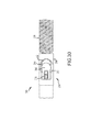
- the implant 90 is a neurological coil.
- the neurological coil implant 90 illustrated in Figs. 1A-1B is shown in a coiled orientation prior to insertion into the microcatheter 14, and the neurological coil implant 90 shown in Figs. 2B-4 is shown in a truncated form for simplicity and disposed in alignment with the axis 54 and the interior of the microcatheter 14 (not shown in Figs. 2B-4 ).
- the neurological coil implant 90 shown in Fig. 2C is shown in an implanted state, disposed in an aneurysm.
- the implant 90 may have a rod 94 engaging the implant 90 in the proximal direction, with the rod 94 including an eyelet 110 engaging a stretch-resistant member 112, as illustrated in Fig. 24 .
- the stretch-resistant member 112 may pass through the eyelet 110 and wrap the eyelet 110 to form a knot or form a hitch knot.
- the neurological coil implant 90 may comprise (i) a coil 116 having a proximal portion and a distal portion; (ii) a stretch-resistant member 112 extending through the coil 116 and having a proximal end and a distal end, the stretch-resistant member 112 distal end coupled to the coil 116 distal portion; (iii) an enlarged proximal end (e.g., ball 96) disposed at the proximal end of the stretch-resistant member 112 and otherwise free of the proximal portion of the coil 116.
- the ball 96 may be spaced apart from the coil 116.
- the ball 96 may be disposed entirely within a lumen of the delivery tube, and the coil 116 may be disposed entirely outside the lumen.
- the rod 94 when engaging the implant interface 80, the rod 94 is disposed in the port 84 in the end cap 82 and terminates with the ball 96 disposed proximal of the end cap 82 in the cavity 86.
- the ball 96 has a cross-sectional area that is less than a cross-sectional area of the port 84, which allows the ball 96 to pass freely through the port 84 when the positioner 40 is in the disengaged orientation illustrated in Fig. 7B .
- the distal tip 88 of the cord 52 When in the engaged orientation illustrated in Figs. 3-4 and 7A , the distal tip 88 of the cord 52 obstructs a portion of the port 84 in the end cap 82, with another portion of the port 84 obstructed by the rod 94.
- the obstruction of the port 84 by the distal tip 88 reduces the available area of the port 84 so that the ball 96 can not pass through the port 84.
- the ball 96 and rod 94 are otherwise unrestrained and free to move and rotate within the cavity 86 and the port 84.
- the ball 96 is retained at the implant interface 80 but not connected to any portion of the positioning system 10.
- the ball 96 is thus free to move independently of the positioning system 10 in any direction within the confines of the cavity 86 and, particularly, is free to move in the direction parallel or radial to the axis 54 of the positioner tube 42, free to move in to a position in which a central axis of the implant 90 is at an angle relative to the axis 54, and free to rotate around the central axis of the implant 90.
- the freedom to rotate the ball 96 and implant 90, facilitated by the illustrated embodiment, is advantageous. It is believed that in existing systems, the implant or a portion of the implant is firmly held by the delivery system and not free to rotate and, when the implant and delivery system are advanced distally to the target site through a microcatheter, the surface of the implant (especially the helical surface of some neurological coils) can induce a torque within the implant when moved along the inner surface of a microcatheter. That torque is stored as a potential energy in a compressed spring within the implant itself and within the connection between the implant and the delivery system.
- the positioning system 10 facilitates the unhindered rotation of the ball 96 and implant 90, thereby avoiding this problem that is believed to exist with existing delivery systems.
- the free rotation of the implant 90 and ball 96 allows the implant 90 to be deployed from the microcatheter 14 at the target site 16 much more gently than with existing systems having a connection that is rigid or that partly or wholly limits movement and rotation between the implant and delivery system, and the free rotation also lowers the force applied to the vasculature during deployment and positioning of the implant 90 at the target site 16.
- the implant interface provides an opening having a first opening area and a second opening area.
- the implant provides an extension that is disposed in the implant interface through the opening, and that has a portion (such as the ball 96) that can pass through the first opening area but can not pass through the second opening area.
- the portion of the extension has an obstruction dimension that defines a structural arrangement that prevents the portion from passing through the structure defining the second opening area at the opening.
- the obstruction dimension also defines the structural arrangement that permits the portion to pass through the structure defining the first opening area. This relationship can be expressed as follows: first obstruction > opening dimension > second opening area
- the implant interface and implant extension use this relationship by having implant interface structure that forms the second opening area to be smaller than the obstruction dimension of the implant extension, to physically block passage of the portion of the extension through the opening, and implant interface structure that forms the first opening area to be larger than the obstruction dimension, to allow passage of the portion of the extension through the opening.
- Equation (1) can be applied to relate the size of the ball 96 to the dimensions of the port 84 and distal tip 88 of the cord 52 by the following relationship: p > b > p - w where "p" is the cross-sectional dimension of the port 84, "b” is the cross-sectional dimension of the ball 96, and "p - w” is the cross-sectional dimension of the port 84 less the cross section dimension of the distal tip 88 of the cord 52.
- Equation (2) is applied to structures having circular cross sections.
- Equation (1) can be applied to structures having non-circular geometries, such as a rod 95, with a triangular cross section, or ports 85 and 89, with a non-circular shape, as illustrated in Figs. 15 and 16 .
- the ball 96 can be replaced with another structure that can effectively pass through an unobstructed port 84 but not pass through an obstructed port 84, such as a disc, hook, or ring structure.
- the distal tip 88 can be modified to obstruct only selected portions of the port 84, or to more closely abut against the inner surface of positioner tube 42 within cavity 86 in order to provide a larger space for the ball 96 to freely rotate or otherwise move within the cavity 86.
- the distal tip 88 can have a cross-sectional shape that is noncircular. For example, as illustrated in Fig. 11B , the cross-section shape of the distal tip 88 can be ovoid and, as illustrated in Fig.
- the cross-section shape of the distal tip 88 can be arcuate.
- the rod 94 can engage the implant 90 at an angle relative to a central axis of the implant 90, or at an angle relative to the axis 54 of the positioner tube 42.
- the illustrated embodiment advantageously provides for the unrestrained axial movement of the ball 96 within the cavity 86 of the implant interface 80.
- the movement of the ball 96 within the cavity 86 is related to the longitudinal length of the cavity 86 and the length of the rod 94 engaging the implant 90 into the cavity 86.
- the rod 94 is of sufficient length to allow the axial movement of the ball 96 and implant 90 in the direction of the axis 54 of the positioner tube 42.
- the axial movement of the ball 96 in the cavity 86 advantageously permits the implant 90 to assume an angled orientation compared to the axis 54 of the positioner tube 42, and articulate, tilt, or pivot around the ball 96.
- the rod 94 can be disposed at an angle 98 to the axis 54 of the positioner tube 42, and that angle 98 is increased as the ball 96 nears an extreme distal position in the cavity 86. That angled orientation and articulation advantageously assists in the relaxation and discharge of potential energy or spring forces in the implant 90, or between the implant 90 and the positioning system 10, as the implant is moved through the microcatheter 14.
- the angulation can be approximately 10-80 degrees between the centerline of the rod 94 and the axis 54 of the positioner tube 42. In one embodiment, the angulation may be approximately 30 degrees. According to other embodiments, angulations of about 0, 10, 20, 40, 50, 60, 70 and about 80 degrees are contemplated. Also, when the implant 90 is observed to have an angled orientation with an imaging system, the operator can readily determine that the implant 90 is not experiencing potential energy or spring forces that could be later released when the implant 90 is deposited at the target site 16. It is believed that existing delivery systems that do not permit angulation or articulation of the implant do not provide this information to the operator.
- the port 85 of the end cap 82 can be non-circular or have a notch that advantageously permits a greater angulation or articulation than can be achieved with the circular-shaped port 84, permitting an angle 99 between the centerline of the rod 94 and the axis 54 of the positioner tube 42.
- the rod can have various cross-sectional shapes, such as a triangular shape of rod 95 as illustrated in Fig.
- the implant interface 80 that interfaces with a complimentary-shaped port 89 in order to maintain a specific articulation (by the alignment of the triangular shape of rod 95 with a triangular notch of port 89) when the implant interface 80 is operated to orientate the rod 95 so that the implant 90 is disposed in a specific direction.
- a slight proximal movement of positioner 40 may be necessary to maintain sufficient contact between the rod 95 and the port 89 illustrated in Fig. 16 .
- the angulation can also be increased or decreased by the adjusting the inner diameter of the port 84 or by adjusting the thickness of the end cap 82.
- a greater inner diameter of the port 84 will allow the rod 94 to assume a greater angle 98, and a thinner end cap 82 will allow the ball 96 to assume a more distal position in the cavity 86 and permit a greater angle of the rod 94 through the port 84.
- a desired angulation can be preset in the design of the implant interface 80 by controlling the length and cross-sectional dimensions of the rod 94, the diameter of the port 84, and the thickness of the end cap 82.
- the port 84 can have a conical shape or a shape in which one end of the port 84 is wider than the other end of the port 84, so that the rod 94 can assume a greater or a preset angle relative to the positioner 40.
- the positioning system 10 of the illustrated embodiment also advantageously captures or recaptures an implant 90 already located at or proximate the target site 16.
- the positioner tube 42 can be advanced distally through the microcatheter 14 (without the implant 90) to an implant 90 already positioned at the target site 16 or, if the implant 90 was just released from the implant interface 80, the positioner tube 42 can be maneuvered proximate to the just-released implant 90.
- Fig. 8A-8C in the order of 8C to 8B to 8A, with the directional arrows of Figs. 8B and 8C reversed.
- the end cap 82 can be moved over the ball 96 so that the ball 96 passes through the port 84 and into the cavity 86 of the implant interface 80, and the distal tip 88 of the cord 52 can be distally advanced to obstruct the port 84 to retain the ball 96 and assume the engaged orientation.
- the implant 90 can then be moved or entirely withdrawn from the target site 16.
- the ball 96 and end cap 82 can be made of a material that can be imaged with standard imaging technologies, such as a radiopaque material, in order to assist with the positioning of the end cap 82 in relation to the ball 96.
- embolic coils suitable for use with the delivery system 10, when modified to include the ball 96 or a combination of the rod 94 and ball 96 include the Sapphire TM , NXT TM , and Nexus TM embolic coils, commercially available from EV3, Inc. of Madison, Minnesota USA.
- the implant 90 of the illustrated embodiment is a neurological coil
- the implant 90 can be any implant that can be inserted with a catheter, such as a stent or stent-graft 90a as illustrated in Fig. 17A or an embolic filter 90b as illustrated in Fig. 17B .
- stents suitable for use with the delivery system 10 when modified to include the ball 96 or a combination of rod 94 and ball 96, include the IntraCoil®, IntraStent®, ParaMount TM PRIMUS TM , and PROTÉGÉ® stents, commercially available from EV3, Inc. of Madison, Minnesota USA.
- a commercially available embolic protection device suitable for use with the delivery system 10, when modified to include the ball 96 or a combination of rod 94 and ball 96 is the SpideRX® embolic protection device, commercially available from EV3, Inc. of Plymouth, Minnesota USA.
- the actuator interface provides the operator the ability to control the movement of the implant as it is positioned by the positioning system, and to mechanically control the selective engagement and disengagement of the implant and implant interface.
- the actuator interface controls the movement of the implant by providing a surface upon which the operator can exert control, so that the controlling motions of the operator are accurately transferred to the implant interface and implant through the positioner.
- the actuator interface provides a relatively stiff proximal end of the positioner that transfers the axially-directed and rotational forces exerted on the actuator interface by the operator to the relatively flexibly distal end of the positioning system with minimal loss due to flexing and twisting of the positioning system.
- the actuator interface provides control of the engagement and disengagement of the implant from the implant interface with a sliding mechanism or slider that controllably and predictably moves the implant interface between the engaged and disengaged orientations.
- the actuator interface also connects to an actuator that permits the operator to controllably and predictably move the slider.
- the actuator interface establishes and maintains a compressive biasing of the implant interface so that the implant interface remains in the engaged orientation by disposing the slider in a distally forward position.
- the compressive biasing of the cord 52 that presses the coining area 72 distally against proximal end of the stopper 70 may be established at the actuator interface 46.
- the proximal end of the positioner tube 42 is fixed to the outer tube 48 by a circumferential weld.
- the slider 50 is slidably fitted into the lumen of the outer tube 48 from the proximal end of the outer tube 48.
- the cord 52 is then preloaded or biased in the distal direction to create compression in the cord 52 in the coining area 72 against the stopper 70 and the slider 50 is tack welded with tack weld 49 to the outer tube 48 while preloaded, to temporarily fix the slider 50 and outer tube 48 together and maintain the implant interface 80 in the engaged orientation.
- the operator slidably moves the slider 50 in the proximal direction, relative to the outer tube 48, with sufficient force to break the tack weld 49 and free the slider 50 so that it can move within outer tube 48.
- a tensile force in the range of approximately 200-500 grams may be required to break the tack weld 49, and little or no particulate matter is liberated with the breaking of the tack weld 49.
- the outer tube 48 may include a band 105 viewable by the operator of the actuator that indicates when the actuator is properly inserted into the actuator 20, in the direction of arrow 106. Specifically, when the outer tube 48 is inserted into the actuator 20, a correct depth of insertion is indicated when the marker 105 is completely within the actuator 20 and no longer viewable by the operator of the actuator, as illustrated in Figs. 26A and 26B .
- the biasing, fixing, and movement of the cord 52 within the positioner 40 can be achieved with a variety of designs.
- the slider 50 can be threaded and received into corresponding threads of the outer tube 48, with the slider 50 axially held in place relative to the outer tube 48 by the threads, and with the biasing and movement of the slider 50 controlled by the rotational movement of the slider 50 relative to the outer tube 48.
- the biasing of the cord 52 and the fixing of the slider 50 can be achieved with a removable locking pin fitted through a common hole through the outer tube 48 and slider 50, temporarily fixed together with an adhesive or the pin can be breakable or bendable with a force that is similar to the force applied when breaking the tack weld 49.
- the slider 50 can also be temporarily fixed in place by a deformable crimp in the outer tube 48 that presses the outer tube 48 against the outer surface of the slider 50, to hold the slider 50 in place relative to the outer tube 48.
- the slider 50 is fixed to the outer tube 48 with a circumferential weld 74 instead of the tack weld 49 and the end weld 51 is replaced with an end cap 75 that is similar to the end cap 82 at the implant interface 80, but having a port 76 that temporarily holds the cord 52 to the end cap 75 with a tack weld 77 similar to the tack weld 49.
- the proximalmost end of the cord 52 is disposed proximal to the port 76.
- the tack weld 77 secures the cord 52 to the end cap 75 and maintains the positioner 40 in the engaged orientation until a predetermined proximally-directed force is applied to the proximalmost portion of the cord 52 that is sufficient to break the tack weld 77.
- the end cap 75 and tack weld 77 can be replaced with a ratchet mechanism that controls or limits movement of the cord 52 in the distal direction to maintain the engaged orientation, and that permits movement of the cord 52 in the proximal direction after the cord 52 is pulled in the proximal direction by a predetermined force similar to the force required to break tack weld 77.
- the slider 50 is connected to the outer tube 48 with a circumferential weld 74.
- the cord 52 is held in the center of the positioner tube 42 along the axis 54 for the entire length of the proximal end of the positioner tube 42, with the proximal end of the cord 52 completely enclosed and held in the location of the axis 54 by the slider 50, the positioner tube 42, and the cord liner 68.
- the external components of the proximal end of the positioner 40 are fixed to each other, but the internal cord 52 remains slidably disposed along the axis 54 except at the proximal-most end of the cord 52 where it is fixed at the end weld 51.
- the actuator interface 46 is of sufficient length so that the operator can hold and bend the actuator interface 46 around a cylindrical object (not shown), such as the operator's finger or a cylindrical object of a predetermined diameter.
- the cord 52 When the actuator interface 46 is held against and wrapped around the cylindrical object, the cord 52 is forced to conform to an arcuate path that has a radius that is greater than a radius of a corresponding arcuate path defined by the outer surfaces of the positioner tube 42 and outer tube 48 that abut the cylindrical object, as measured from a center of the cylindrical object.
- the arcuate path of the cord 52 around the cylindrical object is longer than the corresponding arcuate path at the outer surfaces of the positioner tube 42 and outer tube 48 abutting the cylindrical object, which induces a movement of the cord 52 (and a movement of the distal tip 88) in the proximal direction relative to the actuator interface 46 (and relative to the end cap 82) without the use of the actuator 20.
- the appropriate number of times that the proximal end of the positioner tube 42 be wrapped around the cylindrical object to cause sufficient movement of the distal tip 88 and achieve the disengaged orientation can be determined by trial and error or calculated for various sizes of the positioning system 10.
- the outer tube 48 and the slider 50 can be omitted and the positioner tube 42 and the cord 52 can both directly engage the end weld 51.
- the outer tube 48 encloses bushings 101, 102, and 103 which are disposed within the outer tube 48 and around the slider 50 and the positioner tube 42.
- the bushing 101 is fixed to the inner surface of the outer tube 48 with a circumferential weld at the proximal end of the outer tube 48
- the slider 50 is slidably disposed within the inner surface of the bushing 101 but temporarily fixed to the bushing 101 with a tack weld 104 at the proximal end of the bushing 101.
- the tack weld 104 functions similarly to the tack weld 49 described in the embodiment illustrated in Fig. 3 .
- the bushing 102 is slidably disposed within the outer tube 48, and the distal end of the slider 50 is disposed within the bushing 102 and fixed to the bushing 102 with a circumferential weld at the distal end of the slider 50.
- the bushing 103 is fixed to the inner surface of the outer tube 48 with a circumferential weld at the distal end of the outer tube 48, and the proximal end of the positioner tube 42 is disposed within the inner surface of the bushing 103 and fixed to the bushing 103 with a circumferential weld at the distal end of the bushing 103.
- the slider 50 When the implant interface 80 is in the engaged orientation, the slider 50 is disposed in a distal position within the outer tube 48 and temporarily held in place by the tack weld 104, as illustrated in Fig. 20A .
- a predetermined force is applied to the slider 50 in the proximal direction relative to the outer tube 48, and the tack weld 104 is broken to free the slider 50 to slidably move in the proximal direction within the bushing 101.
- the operator then moves the slider 50 into a proximal position illustrated in Fig. 20B , which corresponds to the disengaged orientation at the implant interface 80.
- the bushing 102 can be replaced with a flared distal end of slider 50 having an outer diameter that is greater than the inner diameter of bushing 101.
- the bushing 101 can be replaced by a crimped proximal section of the outer tube 48 that has an inner diameter that is less than the outer diameter of the bushing 102, and the tack weld 104 can instead temporarily fix the proximal end of the outer tube 48 to the exterior of the slider 50.
- a crimp can be added to the outer tube 48 just distal of the bushing 101 to establish an abutting surface that will impede the proximal movement of the bushing 102.
- the outer tube 48 may have a crimp 120 that forms an internal surface with a diameter that is less than the outer diameter of a portion of the slider 50, so that when the slider moves in the proximal direction an edge 122 abuts the inner surface formed by the crimp 120 and stops the further proximal movement of the slider 50.
- the positioner 42 may include one or more markers 124 on a sleeve 126, which may be fluoro-safe markers.
- Fig. 25 illustrates another embodiment functioning similarly to the embodiment of Fig. 24 . Features that are identical to the other embodiments are not again identified in Figs. 24 and 25 .
- the actuator provides a mechanism that removably engages the actuator interface and causes the controllable and predictable movement of the actuator interface.
- the actuator achieves this function by providing a structure that holds the outer tube in a fixed position relative to the body of the actuator, and a pawl and anvil that pinches the slider and pulls the slider in the proximal direction for a predetermined distance with a predetermined force, and then disengages from the slider to allow disengagement from the actuator.
- the actuator also provides a design that allows the operator to hold the actuator firmly in place, in order to maintain the position of the positioner relative to the target site, and allows the operator to utilize the actuator in a controlled manner that minimizes the movement of the positioner.
- the proximal end of positioner 40 may engage a distal end of the actuator 20.
- the actuator 20 includes a body 21, a receiver section 22, a pawl 23, an anvil 24, a slide return spring 25, a sliding frame 26, and a gripper 27.
- the body 21 may be tubular and provides support for the proximal portion 26a of the sliding frame 26, the receiver section 22, and the slide return spring 25. Enclosing part of the body 21 is the gripper 27 which has two prongs that are pulled by the operator in the proximal direction when operating the actuator 20.
- the gripper 27 is fixed to a pin 28 that passes radially through the gripper 27, through slot 29 in the body 21, and is fixed to the sliding frame proximal portion 26a.
- the sliding frame proximal portion 26a is also moveably connected to the proximal end of the body 21 by the slide return spring 25.
- the sliding frame 26, the gripper 27, and the pin 28 are fixed to each other and move as one when the operator grasps the two prongs of the gripper 27 and the proximal end of the body 21 and slidably moves the gripper 27 in the distal direction relative to the body 21 from the position illustrated in Fig. 21A to the position illustrated in Fig. 21B .
- Figs. 21A and 22A illustrate the actuator 20 in a deactivated position that permits insertion of the actuator interface 46 into the actuator 20.
- Figs. 21B and 22B illustrate the actuator 20 in an activated position in which the slider 50 has been pulled in the proximal direction relative to the outer tube 48 to cause the implant interface 80 to move from the engaged orientation to the disengaged orientation.
- the body 21 may be tubular, and has a distal end connected to the receiver section 22, and an interior lumen slidably containing the partly-cylindrical sliding frame 26.
- the receiver section 22 has a distal surface that includes a funnel that directs the insertion of the actuator interface 46 into a central lumen 31.
- the central lumen 31 has two internal diameters adjacent to each other along the length of the central lumen 31 that correspond to the outer diameters of the slider 50 and the outer tube 48, and an edge between the two diameters that functions as a stop when abutting the proximal end of the outer tube 48.
- the edge of the central lumen 31 limits the proximal movement of the actuator interface 46 when inserted into the central lumen 31, and orientates the slider 50 so that it is disposed in a proximal direction from the central lumen 31 to a predetermined position between the pawl 23 and the anvil 24.
- the proximal end of the body 21 has an enclosed end containing the slide return spring 25 under compression.
- the enclosed end of the body 21 also provides a surface that the operator can hold in place when moving the prongs of the gripper 27 to change the actuator 20 from the deactivated position to the activated position.
- the slide return spring 25 also serves to return the actuator 20 to the deactivated position once the operator releases the prongs of the gripper 27.
- the receiving section 22 also includes a detent 32 fixed in a channel directed radially into the receiving section 22 and into the central lumen 31.
- the detent 32 includes a ball positioned in the channel that is biased towards the central lumen 31 by an internal spring. A portion of the ball of the detent 32 is pressed into the central lumen 31 by the internal spring and, when the actuator interface 46 is inserted into the central lumen 31, the ball presses against the outer surface of the outer tube 48 and frictionally retains the outer tube 48 in the central lumen 31.
- the sliding frame 26 Slidably disposed in the interior of the body 21 is the sliding frame 26.
- the proximal portion 26a of the sliding frame 26 is sized to conform to the interior surface of the body 21, to align and guide the movement of the sliding frame 26 within the body 21.
- the sliding frame 26 is biased in the body 21 to move in the distal direction by the slide return spring 25.
- the distal portion 26b of the sliding frame 26 engages the proximal portion 26a (behind the pawl 23 and the anvil 24 in the cross-sectional views presented in Figs. 21A-22B ) and abuts the proximal surface of the receiver section 22, and provides a generally flat surface that is parallel to and adjacent to the portion of the slider 50 disposed proximal to the central lumen 31.
- the sliding frame distal portion 26b is composed of two opposing members that extend from the cylindrical sliding frame proximal portion 26a, with each member disposed on opposing sides of the pawl 23 and the anvil 24, to hold the pawl 23, the anvil 24, and a pawl spring 30 in position between the two opposing members.
- Figs. 21A-22B only the rear-most (of the view presented) of the two opposing members of the sliding frame distal portion 26b is illustrated.
- a hinge 33 also is disposed on the flat surface of the sliding frame distal portion 26b (between the two opposing members of the sliding frame distal portion 26b) and engages the pawl 23, and the pawl spring 30 biases the proximal end of the pawl 23 away from the sliding frame proximal portion 26a rotatably around the hinge 33, and presses the proximal end of the pawl 23 against the proximal end of the receiver section 22.
- the anvil 24 is carried by the flat surface of the sliding frame distal portion 26b (between the two opposing members of the sliding frame distal portion 26b) and, in the deactivated position illustrated in Figs. 21A and 22A , a space is maintained between the pawl 23 and the anvil 24 sufficient to permit the insertion of the slider 50 between the pawl 23 and the anvil 24.
- pawl 23 and anvil 24 when the sliding frame 26 is moved a predetermined distance in the proximal direction relative to the body 21 and away from the receiving section 22, the pawl 23 and anvil 24 also move because they are engaged to the sliding frame distal portion 26b.
- the proximal movement of the sliding frame 26 also causes the proximal end of the pawl 23 to rotate around hinge 33 because of the bias from pawl spring 30, which is under compression, and causes the distal end of the pawl 23 to press the slider 50 against the anvil 24, thereby pinching and securing the slider 50.
- the slider 50 now secured between the pawl 23 and the anvil 24, is pulled in the proximal direction by the proximal movement of the sliding frame 26, while the outer tube 48 is retained by the edge within the central lumen 31 of the receiver section 22, thereby causing the tack weld 49 to break and move the implant interface 80 into the disengaged orientation.
- the slider 50 is ultimately moved in the proximal direction, relative to the outer tube 48, by almost the same distance traveled by the anvil 24 and the sliding frame 26 in the proximal direction relative to the body 21 and the receiver section 22.
- the receiver section 22 may be made of polycarbonate or ABS, and the pawl 23, the anvil 24, the slide return spring 25, and the pawl spring 30 are made of steel.
- the funnel of the receiver section 22 may be a cone with an angle of 10-120 degrees, and the central lumen 31 has a diameter of 0.010-0.030 of an inch to receive the outer tube 48 and a diameter of 0.006-0.026 of an inch to receive the slider 50.
- the receiver section 22 may be made of polycarbonate, and the pawl 23, the anvil 24, the slide return spring 25, and the pawl spring 30 are made of stainless steel.
- the funnel of the receiver section 22 may be a cone with an angle of 30 degrees, and the central lumen 31 has a diameter of 0.018 of an inch to receive the outer tube 48 and a diameter of 0.014 of an inch to receive the slider 50.
- the operator-manipulated interface surface used by the operator to move the actuator 20 from the deactivated position, illustrated in Fig. 21A , to the activated position, illustrated in Fig. 21B can be implemented with a variety of designs that provide structure to move the sliding frame 26 proximally relative to the receiver section 22 (i.e., the gripper 27 and the prongs disposed on the gripper 27 can be replaced with structures that can controllably move the internal components within gripper 27 as illustrated in Figs. 21A and 22B ).
- the gripper 27 and the prongs disposed on the gripper 27 can be replaced with structures that can controllably move the internal components within gripper 27 as illustrated in Figs. 21A and 22B ).
- the actuator 20 involves the operator compressing the actuator 20 so that the prongs of the gripper 27 (fixed to the sliding frame 26) are moved proximally in relation to the proximal end of the body 21 (fixed to the receiver section 22).
- the internal components i.e., the components within gripper 27
- the external components interfacing with the operator are adapted to facilitate a variety of actuating motions, such as the actuating motions of squeezing a trigger, sliding a switch, turning a wheel, pushing a button, or moving a lever.
- actuating motions such as the actuating motions of squeezing a trigger, sliding a switch, turning a wheel, pushing a button, or moving a lever.
- the body 21 is held by the operator and the gripper 27 is slid in the proximal direction to move the actuator 20 from the deactivated position to the activated position illustrated in Fig. 27 .
- the vasculature of the brain is more tortuous than the vasculature leading to the brain from the groin, a typical access point into a patient's body.
- An instrument disposed in a patient's body between the groin and the brain thus experiences the most tortuous pathway at the distal end of the instrument. This tortuous pathway forces the instrument to bend and subjects the instrument body to increased stresses. Also, any sliding member slidably moved within the instrument, such as a cord, is subjected to greater frictional forces against the sides of the instrument when the instrument is bent or curved.
- pushability can be characterized by a ratio of the force applied to the positioner or cord by the operator at the proximal end of the system ("F1") and the force observed at the distal end of the system (“F2"). Ideally, when the ratio of F1 to F2 approaches unity, this indicates that the force applied to the proximal end translates to an equal or near equal force at the distal end. As can be appreciated, buckling or kinking of the positioner or cord would produce a ratio of F1 to F2 that is not at or not near unity.
- the ratio of F1 to F2 can also be represented as a percentage, indicating that a certain percentage of the force at the proximal end was observed at the distal end.
- the positioning system 10 may provide a pushability that is nearer to unity (100%) than that observed with an existing delivery system ("Nexus/NXT Pusher” refers to a pusher used with the NexusTM and NXTTM coils, commercially available from EV3, Inc. of Madison, Minnesota USA). TABLE 1 Sample System Average pushability Standard deviation Positioning system 94.6% 1.9% Nexus/NXT Pusher 79% 4.6%
- the positioning system also advantageously achieves improved "pushability” or “slidability” by reducing friction between the cord 52 and the positioner tube 42, and between the positioner tube 42 and the microcatheter 14.
- the following equation is a characterization of the frictional forces relating to a flexible inner cylindrical member enclosed within a flexible outer cylindrical member, with the outer member conforming to a curved surface defining a tortuous path, and with the inner member slidably moved within the outer member:
- F 1 / F 2 e ⁇ ⁇
- an advantageous force transfer ratio is achieved by reducing the average friction coefficient at the portions of the positioning system 10 subject to the greatest tortuosity. This may be achieved by selecting specific materials and surface characteristics of mating surfaces at the portions of the positioning system 10 subject to the greatest tortuosity, for example in the distal-most third of the positioner 40.
- the positioning system 10 may perform within a range of tortuosity of 900-4000 degrees, with a force transfer ratio of 16 or less, and an average friction coefficient of 0.045 or less over the length of the 4000-degree tortuous path.
- the positioning system 10 may perform within a range of tortuosity of 2000-4000 degrees, with a force transfer ratio of 16 or less, and an average friction coefficient of 0.045 or less over the length of the 4000-degree tortuous path.
- the cord 52 may be a stainless steel cord with a roughness of less than 50 microinches and the cord liner 68 is a polymer with a roughness of less than 200 microinches, the cord liner 68 and the cord 52 has a hydrophilic coating, or the space between the cord liner 68 and the cord 52 is loaded with a liquid polysiloxane containing a concentration of stearic acid in the range of 2-10%.
- the cord 52 may be a 304 stainless steel cord with a roughness of less than 50 microinches and the cord liner 68 is PTFE with a roughness of less than 200 microinches.
- the materials for the cord 52 and the cord liner 68 may be used for the entire lengths of the cord and cord liner. However, the preferred materials may be provided in the portions of the positioner 40 that are subjected to the 4000 degrees of tortuosity, which is mostly the distal third of the positioner 40. For the proximal two thirds of the positioner 40, a wider selection of materials is available because this portion of the positioner 40 is subjected to less tortuosity (less than 2000 degrees) than the distal third of the positioner 40.
- the positioner 40 may perform with a force transfer ratio of 15 or less and an average friction coefficient of 0.11 or less over the length of a 2000 or less-degree tortuous path in the proximal two thirds of the positioner 40.
- the materials capable of providing a friction coefficient of 0.11 or less are not as limited as with the distal third of the positioner 40.
- Preferable materials suitable for use in the proximal two thirds of the positioner 40 include polyethylene, acetal, or fluoropolymer for the cord liner 68, and a steel or polymer material with a surface roughness of less than 50 microinches for the cord 52. Materials may be polyethylene for the cord liner 68 and steel with a surface roughness of less than 50 microinches for the cord 52.
- AN advantageous force transfer ratio is also achieved at another mating surface of the positioning system 10, i.e., where the positioner tube sleeve 66 slidably moves within the microcatheter 14.
- the preferred material for the positioner tube sleeve 66 is a PTFE heat shrunk material and the preferred material for the microcatheter 14 is a polymer with a relatively smoother surface.
- the flexibility of the positioning system along the length of the system can affect system design and performance, as the flexibility of the system relates to the ability of the operator to control the positioner and the "feel" of the system from the proximal end manipulated by the operator. Also, the suppleness of the distal tip of the positioner relates to the ability of the operator to direct the positioner into the desired position. Maintaining the desired flexibility of a system with a mechanical implant engagement and disengagement system is particularly difficult because the length of the system provides a mechanical connection between the proximal and distal ends of the system that is both small in size but strong enough to cause the engagement and disengagement of the implant from the system.
- the positioning system may achieve the appropriate level of flexibility by providing a relatively rigid structure at the proximal portion of the positioner, a relatively supple structure at the distal portion the positioner, and a transition region in the middle of the positioner that provides a change in flexibility between the proximal and distal portions.
- the proximal portion of the positioner may provide a flexibility (or stiffness) that remains almost constant along the length of this section of the positioner.
- the near-constant flexibility of the proximal portion is achieved by the use of a tube structure.
- the distal portion and the transition region achieve a degree of suppleness with a combination of structural modifications to the tube structure that increases flexibility, the increase in the degree of those structural modifications along the length of the tube structure in the distal direction, and the structural support provided to the positioner by reinforcing structures.
- the flexibility of the distal portion increases along the length of this section, with the greatest suppleness achieved near or at the distal-most end of the positioner.
- the near-constant flexibility of the proximal portion may be achieved by a fully-enclosed tube structure of the positioner without the use of skiving.
- the variable flexibility characteristics of the distal portion and the transition region are achieved by a combination of a tube with skiving, the increase in the degree of the skiving along the length of the tube in the distal direction, and the structural support provided to the positioner by the positioner tube sleeve.
- Fig. 23A illustrates the flexibility of the positioner 40 of the embodiment illustrated in Figs. 3 and 4 (identified as "3G/FX - 0.012" Prox Pusher" in Figs. 23A and 23C ).
- the horizontal axis in Fig. 23A corresponds to the length of the positioner 40, with the end cap 82 (proximate to or within the area of the target site, as illustrated in Fig. 2C ) defining the zero point on the horizontal axis and each marking on the horizontal axis identifying a distance from the end cap 82 in the proximal direction.
- the horizontal axis also corresponds to the anatomical areas in the human body illustrated in Fig.
- Fig. 23A when the end cap 82 is disposed near the target site 16, with distances proximal from the end cap 82 and target site 16 corresponding to the various anatomical features identified in Fig. 23A until the proximal end of the positioner 40 ultimately exits the human body at the groin as illustrated in Fig. 2A .
- the vertical axis in Fig. 23A corresponds to the amount of resistance provided by the positioner 40 along its length when subjected to a 20° deflection.
- the positioner 40 When subjected to a 20° deflection, the positioner 40 resists the deflection, which corresponds to flexibility, by generating a moment. As illustrated in Fig. 23A , the moment observed at the proximal portion of the positioner 40 is approximately constant proximal to the portion of the positioner 40 disposed near the aorta, indicating a near-constant flexibility in this portion of the positioner 40. The moment observed at the distal portion of the positioner 40 decreases distal to the portion of the positioner 40 disposed in the carotid artery, indicating a variable flexibility in this portion of the positioner 40 that increases in the distal direction. As also illustrated in Fig.
- the moment changes at an approximately linear rate in the transition region of the positioner 40 that corresponds to a length of the positioner 40 disposed between the aorta (approximately) and carotid artery (approximately), indicating an approximate linear change in flexibility in this portion of the positioner 40, from a lesser flexibility to a greater flexibility in the distal direction.
- the near-constant flexibility in the proximal portion of the positioner 40, and the approximately linear change in positioner flexibility in the transition region provides a combined flexibility that is interpreted as a good "feel" to the operator manipulating the outer tube 48.
- 23A also advantageously provides a relatively supple distal end in the tortuous anatomy within the brain and distal to the carotid artery.
- the relatively stiff proximal end provides the operator the ability to control the positioner 40.
- the portion of the positioner 40 where the greatest transition from rigid to supple takes place is disposed as distal as possible in the positioner 40, but just proximal of the carotid artery where the anatomy begins to become more tortuous towards the brain and where increased suppleness is desired.
- the positioner 40 provides a variable flexibility profile over the length of the positioner 40.
- the moment measured may be 0.01-0.50 in-lbs at 20° of deflection between the proximal end of the positioner 40 and the portion of the positioner 40 disposed near the aorta, between 55 cm and 80 cm proximally from the target site 16.
- the moment measured may be 0.0001-0.0100 in-lbs at 20° of deflection between the portion of the positioner 40 disposed in the carotid artery and the end cap 82, between 0 cm and 35 cm proximally from the target site 16.
- the moment measured may change from 0.001 in-lbs to 0.100 in-lbs at 20° of deflection between 35 cm and 50 cm from the target site 16.
- the flexibility of the proximal portion may be approximately 0.045 in-lbs at 20° of deflection
- the flexibility of the transition region changes form 0.0005 to 0.045 in-lbs at 20° of deflection
- the flexibility of the distal portion is approximately 0.0005 in-lbs at 20° of deflection.
- the flexibility of the positioner 40 changes at specific rates over the length of the positioner 40, as determined from the measurement of moment in the positioner 40.
- the flexibility may remain constant between the proximal end of the positioner 40 and the portion of the positioner 40 disposed near the aorta, between 55 cm and 80 cm proximally from the target site 16.
- the flexibility may change at a rate of 100-800% between the portion of the positioner 40 disposed in the carotid artery and the end cap 82, between 0 cm and 35 cm proximally from the target site 16.
- the flexibility may change at a rate of 100-1000% between 35 cm and 55 cm from the target site 16.
- the flexibility of the proximal portion may be constant, the flexibility of the transition region changes at a rate of approximately 800%, and the flexibility of the distal portion changes at a rate of approximately 700%.
- Fig. 23B the flexibility profiles of existing thermal, electrolytic, and hydraulic systems are comparable to the flexibility profile of the embodiment illustrated in Figs. 3 and 4 (In Figs. 23B and 23C , "Cordis” refers to Cordis Corporation of Miami Lakes, Florida USA, “MTI” refers to Micro Therapeutics, Inc. of Irvine, California USA, “GDC” refers to the Guglielmi Detachable Coil or GDCID® Detachable Coil commercially available from Boston Scientific Corporation of Natick, Massachusetts, USA, and "Micrus” refers to Micrus Endovascular Corporation of San Jose, California USA).
- the illustrated embodiment has a less flexible proximal portion, between the proximal end of the positioner 40 and the portion of the positioner disposed near the aorta, than existing thermal, electrolytic, and hydraulic systems.
- Fig. 23C is a closer and more detailed view of the information presented in Figs. 23A and 23B , between the distances of 0 and 40 cm (on the x-axis) and between the moments of 0.000 and 0.005 in-lbs (on the y-axis).
- the moment observed decreases (and the flexibility of the positioner 40 increases) continuously until reaching the last 4 cm, where measurements become less reliable.
- the positioner 40 of the illustrated embodiment has a flexibility that changes continuously along the length of the distal portion, and especially along the 5-35 cm proximal to the end cap 82.
- the distal end of the positioner 40 provides a flexibility that changes in the distal direction by 100-800% between 35 cm and 0 cm from the end cap 82, for example, by approximately 700%.
- Fig. 23C the distal end of the positioner 40 provides a flexibility that changes in the distal direction by 100-800% between 35 cm and 0 cm from the end cap 82, for example, by approximately 700%.
- the distal end of the positioner 40 provides a degree of flexibility that changes in the distal direction between 35 cm and 10 cm from the end cap 82, decreasing by 100-900%, for example, by 500%.
- existing non-mechanical systems do not provide distal portions with flexibilities that change as significantly as seen with the positioner 40, and it is also believed that existing non-mechanical systems do not provide distal portions with flexibilities that change between 10 and 35 cm from the distal-most end of these systems.
- the flexibility of the tip of the positioner 40 may be important to proper positioning of the implant 90 at the target site 16.
- the distal tip flexibility of the embodiment illustrated in Figs. 3 and 4 has been demonstrated to provide a more flexible tip as compared to other systems when subjected to a longitudinally compressive force, as shown in Table 2.
- TABLE 2 Sample System Buckling Force Positioning system 1.0 g Micrus Pusher 3.0 g
- a mechanically-operated positioning system can be flexible and small enough to reach the target site, but remain strong enough to permit the operator to control the positioning and mechanical operation of the implant interface.
- the positioning system achieves a mechanically-operated implant engagement and disengagement system with an appropriate profile, or size, by utilizing materials and surfaces with variable friction coefficients, strengths, and flexibilities appropriate for a positioner subjected to a tortuous pathway.
- the outer diameter of the distal end of the positioner 40, at the distal end of the pusher tube 42, may be small enough to reach the target site 16 while permitting the proper operation of the implant interface 80 from a mechanical system connecting the implant interface 80 to the proximal end of the positioning system 10.
- the outer diameter of the distal end of the positioner 40, at the distal end of the pusher tube 42, may have a 0.008-0.018 inch outer diameter, for 304 stainless steel hypotube or steel alloy.
- the outer diameter of the distal end of the positioner 40, at the distal end of the pusher tube 42, may have a 0.012 inch outer diameter, for 304 stainless steel hypotube.
- the operator may repeatedly move the additional coil back and forth (by moving the delivery system) in order to nest the coil within the aneurysm between the already-implanted coils, and to evaluate whether the aneurysm can accommodate the implantation of more coils. It is also believed that the repeated movement of the delivery system and additional coil causes the system and coil to experience friction where the system and coil slidably move within a delivery catheter and where the additional coil contacts already-implanted coils.
- connection point between the system and coil can experience significant stresses and, when combined with the repeated back-and-forth movement, possibly cause material fatigue and the fracture of the connection point, resulting in the premature disengagement of the coil from the system. It is further believed that existing delivery systems that rigidly or firmly engage the additional coil, or that impede the free movement or rotation of the coil relative to the system, permit the development of the stresses relating to the repeated back-and-forth movement of the system and coil.
- the positioner of the various embodiments avoids or minimizes the development of stresses at the interface between the positioner and implant by permitting the unrestrained movement of the implant relative to the positioner, within the limitations defined by the implant interface.
- the development of implant interface stresses is minimized or avoided because the ball, rod, and implant are able to move in the axial and radial directions compared to the axis of the positioning system, to rotate about an axis of the rod or implant, and to move angularly so that implant is at an angle as compared to the axis of the positioning system.
- a proximal movement (or pull) of the positioner 40 causes the implant interface 80 to engage and pull the ball 96 and pull the implant 90 in a proximal direction, which may cause stresses at the ball 96 and rod 94 when the implant 90 resists the proximally-directed movement because of friction from contact with the inside of the microcatheter 14 or with already-implanted implants.
- the implant 90 is able to assume an orientation, angulation, or rotational position that prevents or minimizes the development of stresses from the bending or turning of the implant 90 relative to the positioner 40.
- a distal movement (or push) of the positioner 40 causes the distal surface of the implant interface 80 (the end cap 82) to engage and push the proximal surface of the implant 90 and push the implant 90 itself in the distal direction, without applying axially directed forces to the ball 96 or rod 94.
- the ball 96 and rod 94 are thus not subjected to a significant stress when the implant 90 is moved in the distal direction because all or a majority of the force imparted from the positioner 40 to the implant 90 is imparted directly to the implant 90 without the involvement of the ball 96 or rod 94, although there may be some radially directed forces applied to the ball 96 or rod 94 by contact with the end cap 82 or positioner 40.
- the implant 90 In the distal movement of the positioner 40 and implant 90, the implant 90 remains capable of assuming an orientation or rotational position responsive to forces resulting from the contact of the implant 90 with the end cap 82, with the inside of the microcatheter 14, or with already-implanted implants. Also, because the implant 90 abuts the end cap 82, the operator is provided with a tactile sensation regarding the degree of resistance resulting from attempts to insert or nest the implant 90 within the aneurysm or among the already-implanted implants.
- the embodiment illustrated in at least Figs. 3 and 4 provides a coil positioning system 10 that may be already in the engaged orientation when removed from packaging and prior to insertion into a patient, as illustrated in Fig. 8A for example.
- the illustrated positioner 40 and implant 90 thus provide a system that is ready for use out of the package, subject to the requisite steps common to such medical procedures that are performed before deploying the coil, e.g., the insertion of a microcatheter into the patient and the insertion of the delivery system into the microcatheter.
- the embodiment illustrated in at least Figs. 3 and 4 also provides a coil positioning system that directly connects the actuation of the detachment mechanism with the detachment of the implant from the delivery system, without an intermediary process to initiate and complete coil detachment.
- the direct connection between slide 50 and cord 52 causes the movement of the slider 50 to move the cord 52 away from the port 84, thereby achieving a detached status because the implant 90 is no longer securely retained by the positioner 40, as the ball 96 is free to pass through port 84.
- the coil structure of the illustrated implant 90 further facilitates the movement of the ball 96 through port 84 because the coil structure expands or adjusts to the anatomy of the target site 16, which causes the implant 90 to move distally away from the end cap 82 and thereby facilitate the movement of the ball 96 through the port 84.
- the illustrated embodiment may achieve an out-of-package preparatory time of approximately 15 seconds and a detachment time of less than 1 second.
- preparatory and detachment times of the illustrated embodiment provide a system that permits a fast and efficient deployment of implants at a target site.
- the advantageous preparatory and detachment times reduce the length of time required to prepare the positioning system and advantageously increases the efficiency of the procedure, thereby allowing the practitioner to attend to other duties during the invasive medical procedure.
- Figs. 29-33 illustrate embodiments of a detachment system.
- Figs. 29 , 32 and 33 illustrate detachment system 200 following successive steps to detach embolic coil 206, also referred to herein as implant 90, from insertion tool 214.
- Insertion tool 214 comprises an elongate pusher tube 216, also referred to herein as tube 42, a tubular distal tip 218 having distal opening 219 and side wall 204 defining lumen 208, also referred to herein as cavity 86, there through.
- Distal opening 219 may have a cross-sectional dimension substantially similar to a cross-sectional dimension of tube 216 or, as disclosed with regard to port 84, smaller than a cross-sectional dimension of tube 216.
- Pusher tube 216 may be comprised of the same materials and fabricated using the same processes as those described previously for positioner tube 42.
- Tubular distal tip 218 may be comprised of metal, ceramic, polymer or other materials known in the art.
- Pusher tube 216 may be permanently affixed to tubular distal tip 218 by welding, adhesives, crimping, or other means. In one or more embodiments, distal end of pusher tube 216 inserts into a socket within the proximal end of tubular distal tip and is affixed by epoxy adhesive.
- Side wall 204 is cut, molded, or otherwise configured to define paddle 240, partial aperture 244 surrounding a portion of paddle 240, and shoulder 246.
- Paddle 240 and partial aperture 244 may be of various sizes and/or shapes.
- An example of a suitable shape for paddle 240 can be seen in a top view in Fig. 30 , which also reveals a possible position of ball 232, also referred to herein as ball 96, prior to deployment of system 200.
- Other shapes, positions, and orientations of ball 232 are contemplated, including but not limited to egg shaped and polyhedral.
- ball 232 prior to deployment of system 200 to release coil 206, ball 232 has freedom of movement within lumen 208 axially, rotationally, and by pivoting (tilting).
- the ball 232 may be disposed within lumen 208, such that coil implant 206 is configured to at least one of: (i) move axially relative to elongate pusher tube 216 (ii) tilt about ball 232 within a range of angles relative to the longitudinal axis of elongate pusher tube 216 and (iii) rotate about its own longitudinal axis while pull wire 226 is contacting ball 232.
- the exact position of ball 232 may consequently vary from that illustrated in Fig. 30 .
- pull wire may be comprised of one or more tapering segments 226A and 226B in order to provide increased flexibility in the distal or other region of insertion tool 214, eliminating interferences to smooth sliding between pull wire and roughness or ledges on the inner surface of wall 204, and other advantages.
- Tapering segments 226A or 226B may provide one or more smooth or interrupted transitions from a first segment of pull wire 226 having a first cross-sectional dimension to a second segment of pull wire 226 having a second cross-sectional dimension.
- a segment may taper from a first cross-sectional dimension to a second, smaller cross-sectional dimension. The taper may occur in a proximal or distal direction.
- Pull wire 226 is axially moveable within alignment member 228; however, alignment member 228 helps prevent unintended circumferential translation of pull wire 226.
- pull wire 226 is loaded through alignment member 228, through lumen 208, until it reaches ball 232, or as far as coil 206.
- pull wire 226, which may be tapered, may be threaded through the distal end of insertion tool 214 to permit loading of ball 232, and then retracted or advanced to releasably retain coil 206.
- pull wire 226 urges ball 232 against paddle 240, and ball 232 has freedom of movement within aperture 244.
- Partial aperture 244 permits paddle 240 to be urged slightly out of the plane of sidewall 204, and paddle 240 in turn places some pressure on ball 232.
- Axial motion of ball 232 in a distal direction is prevented by shoulder 246, thereby preventing ball 232 from exiting the distal tip 218.
- ball 232 is retained within distal tip of insertion tool 214 prior to deployment of system 200, ball 232 advantageously has axial, rotational, and pivotal freedom of movement within the distal tip 218 of insertion tool 214 prior to retraction of pull wire 226 by an operator.
- pull wire 226 is retracted proximally of ball 232.
- insertion tool 214 may be moved distally to pull wire 226.
- ball 232 is urged by paddle 240 into the lumen 208 of insertion tool 214.
- Axial movement of ball 232 is no longer restricted in a distal direction by shoulder 246, and ball 232 (and in some embodiments coil 206) is free to exit distal tip 218.
- Fig. 33 illustrates coil 206 following its exit from distal tip 218.
- Fig. 34 illustrates a similar detachment mechanism which operates generally according to the same principles of the embodiment described in relation to Figs. 29-33 above.
- detachment system 300 provides mechanisms for detachment of embolic coil 306 from an insertion tool.
- the insertion tool comprises an elongate pusher tube and has a paddle 340 covering at least a portion of a side wall aperture.
- paddle 340 may be oriented parallel or transverse (e.g., perpendicular) to the longitudinal axis of the insertion tool.
- paddle 340 may be a portion of the tube that protrudes radially outward, providing a recess within which attachment member 332 may reside when in contact with pull wire 326.
- Embolic coil 306 is attached to attachment member 332, which initially resides within the tube, for example at or near paddle 340.
- Attachment member 332 may be any of a variety of shapes, including spherical, ovoid, polyhedral, cylindrical, etc. Also cut or otherwise configured or disposed upon a side wall is alignment member 328, shown in the example of Fig. 34 as opposite paddle 340.
- pull wire 326 in preparation for deploying system 300, pull wire 326 is loaded through alignment member 328 until it reaches attachment member 332, as far as coil 306, or beyond coil 306. Pull wire 326 urges attachment member 332 against paddle 340 or into recess (not shown). Axial motion of attachment member 332 in a distal direction is prevented by a portion of the tube distal to paddle 340 or recess, thereby preventing attachment member 332 from exiting the distal end of the tube. During deployment of detachment system 300, pull wire 326 is retracted proximal of attachment member 332. Axial movement of attachment member 332 is then no longer restricted in a distal direction, and attachment member 332 (and in some embodiments coil 306) is free to exit the tube.
- an elongate pusher tube 216 can be preformed such that an inner wall thereof defines a lumen having a non-circular profile so as to prevent, limit, or reduce lateral motion of pull wire 226 relative to longitudinal axis of tube 216.
- a region of the inner wall defining a lumen has a non-circular cross-sectional shape in a plane perpendicular to the longitudinal axis of the distal tip 218, the plane intersecting a point of contact between the pull wire 226 and the ball 232.
- the inner wall may be formed, for example, using extrusion, heat setting, swaging, die forming, or other techniques.
- wall thickness of a distal tip 218 may Be varied.
- a lumen with non-circular cross-sectional dimension might define voids V not occupied by either the pull wire 226, portions of the ball 232 within the lumen, or other structures.
- ball 232 extends at least partially through an aperture 244 or recess, voids are defined by the open space between portions of ball and pull wire 226 remaining within the lumen and the wall surface of the lumen.
- an elongate pusher tube 216 may be indented into what would otherwise be voids, so as to reduce the size of or eliminate the voids.
- the distal tip 218 may be manufactured in conjunction with a forming mandrel inside the tube that preserves the desired lumen shape.
- the external surface of the distal tip 218 has concave regions 217A at least over the distal region of the distal tip and corresponding convex regions 217B on the internal surface of the distal tip to restrict lateral motion of the pull wire 226.
- Indented tubes may be formed for example using the above listed techniques, crimping, or other techniques.
- voids in the vicinity of the pull wire 226 may also be filled with space-occupying material 227 so as to prevent, limit, or reduce lateral motion of the pull wire 226 relative to longitudinal axis of tube 216.
- a distal tip 218 with variable wall thickness may be formed by means of the above listed techniques.
- a distal tip 218 with variable wall thickness may provide an outer profile of substantially circular or non-circular cross-sectional dimension and an inner profile of circular or non-circular cross-sectional dimension.
- the inner profile may be smaller than the outer profile, the two profiles sharing or not sharing a common center or central axis.
- the inner profile may be configured to have a central point away from a central point of the outer profile, such that the thickness of a region of distal tip 218 near pull wire 226 is greater than a region of distal tip 218 opposite pull wire 226.
- Each of the inner profile and outer profile may vary or be consistent along the length or a portion of the length of tube 216.
- the inner profile may have a first configuration along a distal segment of tube 216 and a second configuration along a proximal segment of tube 216.
- the outer profile may have a first configuration along a distal segment of tube 216 and a second configuration along a proximal segment of tube 216. Any one of said configurations may be as described herein.
- an inner wall defining a lumen of a tube 216 may be shaped to receive a ball 232 and a pull wire 226 having a region of a crescent or other non-circular cross-sectional shape.
- the lumen of the tube 216 may provide a lumen size and shape to which the ball 232 and the pull wire 226 conform when placed together within the lumen.
- an inner wall defining a lumen of a tube 216 having non-circular cross-sectional geometry may reduce or eliminate voids in lumen of tube 216 around and between pull wire 226 and ball 232. This configuration reduces lateral motion of pull wire 226, especially lateral motion due to limitations of manufacturing tolerances, and thereby reduces unintended premature release of ball 232.
- the pull wire 226, or a portion thereof may have a non-circular cross-sectional shape.
- a region of the pull wire 226 may have a non-circular cross-sectional shape in a plane perpendicular to the longitudinal axis of the elongate pusher tube 216, the plane intersecting a point of contact between the pull wire 226 and the ball 232.
- the cross-sectional shape of the region may fill at least a substantial portion of the lumen not otherwise occupied by ball 232.
- a region of the pull wire 226 has a substantially crescent-shaped cross-sectional geometry.
- the region of pull wire 226 may have a concave first side facing toward the ball 232.
- the first side may contact the ball 232.
- the region of pull wire 226 may have a convex second side facing away from the ball 232.
- the second side may contact the wall of the tube 216.
- Crescent cross section shaped wire can be formed for example by swaging, crimping, stamping, forging, plating, EDM, welding, grinding, or other techniques.
- a distal portion of the pull wire 226 has a non-circular cross section
- a proximal portion of the pull wire 226 has a substantially circular cross section.
- an entire length of the pull wire 226 has a non-circular cross section.
- the radius of curvature of the concave side can correspond to the radius of curvature of the ball 232.
- the radius of curvature of the concave side can be smaller than the radius of curvature of the ball 232 such that contact between the two is limited to two lines or points rather than having contact over the entire concave surface of pull wire 226. In some embodiments, to reduce friction of pull wire 226 against ball 232, the radius of curvature of the concave side can be greater than the radius of curvature of the ball 232 such that contact between the two is limited to a point rather than having contact over the entire concave surface of pull wire 226.
- a pull wire 226 having non-circular cross-sectional geometry may reduce or eliminate voids in lumen of tube 216 around and between pull wire 226 and ball 232. This configuration reduces lateral motion of pull wire 226, especially lateral motion due to limitations of manufacturing tolerances, and thereby reduces unintended premature release of ball 232.
- the paddle 240 may be curved inward toward the central axis of the tube 216 by means of overbending the paddle 240 beyond the elastic limit of the material from which the paddle 240 is made so that the paddle 240 acquires a permanent set in a curved inwards position.
- the paddle 240 covers at least a portion of an aperture 244 by extending from the tube 216 (e.g., tubular distal tip 218) at an edge of the aperture 244.
- no part of the paddle 240 extends a radial distance from the axis of the tube 216 greater than the outer radius of tube 216.
- a portion (e.g., a proximal portion) of the paddle 240 extends a radial distance from the axis of the tube 216 greater than the outer radius of tube 216.
- a portion (e.g., a distal portion) of the paddle 240 extends inward toward the longitudinal axis of the tube 216 to be a radial distance below the outer surface of the tube 216. This inward turn or curvature may be provided by bending, heat setting, or other means. The amount of bending applied can be controlled by means of dies, crimping, or other techniques, optionally in conjunction with use of an internal mandrel during manufacturing.
- the paddle 240 can be heat set into a curved inwards position by applying heat to at least the paddle portion 240 of the tube 216 while the paddle portion 240 is at or near the desired curved inwards position.
- Local application of heat can be applied using for example laser energy, CO 2 laser energy, heated dies, RF heating, or other techniques.
- the amount of bending applied can be controlled by means of heated dies, thermally conductive molds, or other techniques, optionally in conjunction with use of an internal mandrel during manufacturing. Materials which have shape memory properties, such as Nitinol, are particularly suitable for heat setting techniques.
- a pull wire 226 may include a stopper 226A, forming an enlarged region along its length.
- a stopper 226A can have cross-sectional shape and size distinct from the cross-sectional shape and size of other portions of the pull wire 226.
- the pull wire 226 may have a substantially circular cross-sectional shape on portions proximal or distal to the stopper 226A.
- a stopper 226A may have a non-circular cross-sectional shape such as square, rectangular, triangular, oval, or other shapes.
- a pull wire 226 may extend within a lumen through a reduced portion 229 of the lumen.
- Pull wire 226 may be aligned within reduced portion 229 to allow portions of pull wire 226 to be disposed against a side wall of tube 216 or away from a side wall of tube 216.
- Pull wire 226 may extend any length within tube 216, and contact ball 232, which may be within or near an aperture or otherwise disposed within a lumen of tube 216.
- the reduced portion 229 may be formed by an alignment member 228 extending from a wall of tube 216 (e.g., tubular distal tip 218).
- the reduced portion 229 may be a portion of a lumen of tube 216 having a tapered or reduced cross-sectional dimension relative to other portions of the lumen.
- a stopper 226A may be disposed on pull wire 226 distal to the reduced portion 229.
- the pull wire 226 may have a cross-sectional profile along a portion proximal or distal to the stopper 226A, wherein the stopper 226A has a different cross-sectional profile.
- pull wire 226 may have a substantially circular cross-sectional profile along a portion proximal or distal to the stopper 226A, and the stopper 226A may have a non-circular cross-sectional profile along its length.
- the reduced portion 229 may have a cross-sectional profile that corresponds to the cross-sectional profile of the stopper 226A.
- the cross-sectional profile of the reduced portion 229 may be geometrically similar to the cross-sectional profile of stopper 226A.
- the cross-sectional profile of the reduced portion 229 may have substantially the same shape as the cross-sectional profile of stopper 226A.
- the second cross-sectional profile of the stopper 226A may have at least one cross-sectional dimension that exceeds at least one cross-sectional dimension of a proximal portion of pull wire 226.
- the second cross-sectional profile of the stopper 226A may have at least one cross-sectional dimension that exceeds at least one cross-sectional dimension of the reduced portion 229 through which pull wire 226 extends.
- travel of the stopper 226A through the reduced portion 229 is limited while the stopper 226A is in a first rotational state relative to the reduced portion 229. According to some embodiments, travel of the stopper 226A through the reduced portion 229 is permitted while in a second rotational state relative to the reduced portion 229 ( Fig. 40B ). Where rotational states of the stopper 226A are controlled by a user, travel of the stopper 226A through the reduced portion 229 and proximal travel of pull wire 226 may be reduced or prevented until a given rotational state of the stopper 226A is controllably selected by the user. Accordingly, premature proximal travel of pull wire 226 may be reduced or eliminated, thereby reducing unintended longitudinal retraction of the pull wire 226 and premature release of ball 232.
- a stopper 226A can be formed by adding material to the pull wire 226, such as by welding, electrodeposition, attaching a tubular component for example by welding, brazing, soldering, or adhering, or by other means.
- a stopper 226A can be formed by removing material from the pull wire 226, such as by grinding, swaging, crimping, EDM, or other means.
- a stopper 226A can be formed by sliding a supplemental component over the pull wire 226, followed by swaging or crimping the supplemental component to form a frictional connection (e.g., interference fit) between the two.
- a stopper 226A can be formed by coining a region of the pull wire 226 so as to flatten the pull wire 226 such that stopper 226A is wider than the wire diameter in a direction normal to the wire axis and also narrower than the wire diameter in a different direction normal to the wire axis.
- a stopper 226A may have a proximal surface 230 that is parallel to a distal surface 231 of the alignment member 228 so that, when the distal surface 231 is not normal to axis of the pull wire 226, the pull wire 226 will tend to align in a preferred rotational state in relation to the alignment member 228.
- Said rotational state may be an orientation that does not allow stopper to pass through hole in alignment member 228.
- Alignment member 228 may be oriented at many angles to axis of pull wire 226. In some embodiments angles of 45 degrees to 135 degrees are contemplated.
- a ball 232 may have a projection 232A that is configured to extend at least partially into an aperture 244 of a tube 216 (e.g., tubular distal tip 218).
- the projection 232A on the ball 232 can have a cross-sectional shape such as square, rectangular, triangular, oval, or other shapes.
- Protrusion height can vary but desirably is equal to the wall thickness of tube 216 so that projection 232A does not extend beyond tube outer surface which could undesirably become lodged against stents, calcium deposits, or other luminal roughness during positioned delivery.
- a projection 232A can be formed by adding material to the ball 232, such as by welding, electrodeposition, attaching a tubular component for example by welding, brazing, soldering, or adhering, or by other means.
- a projection 232A can be formed by removing material from the ball 232, such as by grinding, swaging, crimping, EDM, or other means.
- a projection 232A can be formed by coining a region of a ball 232 so as to raise the projection from the surface of the ball. In some embodiments fabrication of the projection 232A will deform the ball 232 such that the ball 232, without considering the projection 232A, is no longer spherical, but rather has a flattened shape, an egg shape, or other shapes.
- one or more protrusions 233 of a projection 232A are contemplated to be substantially normal to axis of catheter.
- one or more protrusions 233 may form non-orthogonal angles with the axis of the catheter. Such angles may be between about 60 degrees and about 120 degrees. In some embodiments, as shown in Fig.
- a width of a projection 232A at a surface farthest from the ball 232 will be wider than a width of the projection 232A at region of contact with the ball 232, such that the shoulder 246 of tube 216, when forced against the projection 232A, tends to displace the ball 232 to a position of greater engagement within the aperture 244, thereby enhancing security of the ball 232.
- a surface of shoulder 246 may be parallel to a surface of a protrusion 233 to enhance securement of the ball 232.
Abstract
Description
- This disclosure relates to therapeutic implant delivery and retrieval systems and, more particularly, to a system with a member that mechanically engages an implant to be positioned in a body. The positioning includes delivering and deploying an implant at a target site, or removing an implant from the target site. The disclosure also relates to implants and, more particularly, to implants adapted to be mechanically retained by a delivery and retrieval system.
- Sometimes a body cavity, such as an aneurysm, is located in a surgically remote, delicate, and torturously formed region, such as within the cerebral vasculature, that requires a specialized delivery system to navigate to the region and safely and reliably deliver a coil implant.
- The positioning system includes an actuator operated by an operator, a positioner engaging the actuator, and an implant interface at the distal end of the positioner that engages a complementary portion of an implant.
- The positioner provides the operator the ability to move the implant controllably through a microcatheter or delivery tube and to position the implant properly at a target site. The positioner provides a mechanical system for selectively engaging the implant, while maintaining a narrow profile and sufficient flexibility to navigate the tortuous pathways within the body that are navigated to reach the target site. While providing a small and flexible profile, the positioner has sufficient strength to allow the operator to controllably move the implant through the microcatheter, and the mechanical engagement with the implant remains functional and controllable when subjected to high tortuosity near the target site. The mechanical engagement of the positioner to the implant also maintains the proper orientation of the implant throughout the positioning procedure by allowing the implant to rotate and discharge any torsional forces induced during the movement of the implant to the target site. The positioner also allows the operator to control the movement of the positioner and implant by properly translating the control exerted by the operator into predictable and responsive movements near the target site.
- The positioner achieves advantageous performance and overcomes problems believed to be limiting the performance of existing systems by providing a mechanical implant engagement system that permits free rotating movement while retaining the implant, and that provides minimal direct contact with the implant, so as to minimize the build up of torsional forces between the positioner and implant when the implant twists and rotates while moving through the microcatheter. The contact between the positioner and implant is minimized and fully rotatable so that the implant will maintain an acceptable orientation as it progresses to the target site while independently reacting to any forces acting on the implant when navigating the tortuous pathway to the target site. The minimization of contact and torsional forces between the positioner and implant improves the operator's ability to control the positioner, and improves accuracy in the positioning of the implant at the target site. The positioner also achieves advantageous performance by providing a mechanical implant engagement system that is narrow, flexible, and controllable. The positioner provides a narrow profile by employing a mechanical implant engagement system in which the implant moves in an axial direction when engaging or disengaging the positioner, without the need for transverse movement of the implant. The positioner provides improved flexibility by using a support structure that has varying flexibility along its length, with greater flexibility corresponding to more tortuous portions of the pathway to the target site. The positioner provides improved controllability by employing materials and surfaces that provide coefficients of friction selected with regard to the tortuosity of the pathway to the target site, and that are utilized in the positioner so as to correspond to the most tortuous portions of the pathway to the target site. The positioner also provides improved control by more fully and accurately communicating the control movements exerted by the operator to the movement of the positioner at the target site. The positioner also provides a system that permits the mechanical engagement or disengagement of the implant without the use of hydraulic, thermal, electrical, or chemical energy.
- The implant interface allows the operator to mechanically control the engagement and disengagement of the implant to the positioner, and allows the positioner to retain the implant in a way that minimally contacts the implant, that permits movement in all directions of motion and rotationally, and that allows the implant to move axially and without radial movement when engaging and disengaging the implant interface. The implant interface provides mechanical control of the engagement and disengagement of the implant by retaining a member engaging the implant. The member is introduced into the implant interface through an opening in the positioning system, and retained at the implant interface by obstructing the opening at least in part, or fully, so as to physically prevent the complete exit of the member back through the opening. The obstructing is achieved with a movable elongate member disposed along the length of the positioning system with a distal end that obstructs the opening. By obstructing the opening and not fixedly restraining the implant, the implant remains free to move according to the limitations defined by the implant interface, which includes movement in the axial and radial directions compared to the axis of the positioning system, rotational movement about an axis of the implant, and angular movement that disposes the implant at an angle as compared to the axis of the positioning system. Furthermore, by obstructing the opening and not directly restraining the implant, the contact between the implant interface and the implant is minimized.
- The therapeutic implant can be any implant that can be retained and positioned by the positioning system. The implant is retained by the implant interface with an extension engaging the implant. The extension can be a part of the implant when the implant is made, a modified portion of the manufactured implant, or attached to the implant after initial manufacturing. The extension provides an end that is disposed at a distance from the implant body, and allows the implant interface to engage and secure the implant by securing the end of the extension. The implant body itself; however, is not connected to the implant interface. The end of the extension may be a ball, but can take other forms.
- The positioning system facilitates the unhindered rotation of the ball and implant, thereby avoiding the sudden or uncontrolled release of energy imparted to the system by the movement of the system to the target site. The free rotation of the implant and ball allows the implant to be deployed from the microcatheter at the target site much more gently than with existing systems having a connection that is rigid or that partly or wholly limits movement and rotation between the implant and delivery system, and the free rotation also lowers the force applied to the vasculature during deployment and positioning of the implant at the target site.
- The implant interface also advantageously provides for the unrestrained axial movement of the ball within a cavity of the implant interface. The movement of the ball within the cavity is related to the longitudinal length of the cavity and the length of the rod engaging the implant and disposed in the cavity. When the implant and positioner are both advanced in the distal direction, friction against the surface of the implant will cause the ball to move axially to an extreme proximal position in the cavity and the proximal surface of the implant will abut the distal surface of positioner. When the positioner is advanced in the proximal direction, friction against the surface of the implant will cause the ball to move distally to an extreme distal position in the cavity, and that there will be minimal or no frictional contact between the positioner and implant. The differing frictional characteristics related to the axial movement of the ball in the cavity, and the degree of contact between implant and the implant interface, provides a "friction push" and a "frictionless pull" to the positioning system that is appealing to the operator because it provides an additional tactile sensation related to the movement of the system.
- The axial movement of the ball in the cavity advantageously permits the implant to assume an angled orientation compared to the axis of the positioner, and articulate or pivot around the ball. That angled orientation and articulation advantageously assists in the relaxation and discharge of potential energy or spring forces in the implant, or between the implant and the positioner, as the implant is moved through the microcatheter.
- The positioner also advantageously captures or recaptures an implant already located at or proximate the target site.
- The actuator interface provides the operator the ability to control the movement of the implant as it is positioned by the positioning system, and to mechanically control the selective engagement and disengagement of the implant and implant interface. The actuator interface controls the movement of the implant by providing a surface upon which the operator can exert control, so that the controlling motions of the operator are accurately transferred to the implant interface and implant through the positioner. The actuator interface provides a relatively stiff proximal end of the positioner that transfers the axially-directed and rotational forces exerted on the actuator interface by the operator to the relatively flexibly distal end of the positioning system with minimal loss due to flexing and twisting of the positioning system. The actuator interface provides control of the engagement and disengagement of the implant from the implant interface with a sliding mechanism that controllably and predictably moves the implant interface between the engaged and disengaged orientations. The actuator interface also connects to an actuator that permits the operator to controllably and predictably move the slider. In addition, the actuator interface establishes and maintains a compressive biasing of the implant interface so that the implant interface remains in the engaged orientation by disposing the slider in a distally forward position.
- The actuator provides a mechanism that removably engages the actuator interface and causes the controllable and predictable movement of the actuator interface. The actuator achieves this function by providing a structure that holds the outer tube in a fixed position relative to the body of the actuator, and a pawl and anvil that pinches the slider and pulls the slider in the proximal direction for a predetermined distance with a predetermined force, and then disengages from the slider to allow disengagement from the actuator. The actuator also provides a design that allows the operator to hold the actuator firmly in place, in order to maintain the position of the positioner relative to the target site, and allows the operator to utilize the actuator in a controlled manner that minimizes the movement of the positioner.
- In order to minimize the force required from the operator, and to lessen the potential for failure of instrument components, the positioning system advantageously achieves improved pushability. The force applied to the proximal end of the positioner translates to an equal or near equal force at the distal end of the positioner. The positioning system also advantageously achieves improved pushability by reducing friction between the cord and the positioner, and between the positioner and the microcatheter. Advantageous force transfer ratio is achieved by reducing the average friction coefficient at the portions of the positioning system subject to the greatest tortuosity. This may be achieved by selecting specific materials and surface characteristics of mating surfaces at the portions of the positioning system subject to the greatest tortuosity.
- The positioning system may achieve the appropriate level of flexibility by providing a relatively rigid structure at the proximal portion of the positioner, a relatively supple structure at the distal portion the positioner, and a transition region in the middle of the positioner that provides a change in flexibility between the proximal and distal portions. The proximal portion of the positioner may provide a flexibility (or stiffness) that remains almost constant along the length of this section of the positioner. The near-constant flexibility of the proximal portion is achieved by the use of a tube structure. The distal portion and the transition region achieve a suppleness with a combination of structural modifications to the tube structure that increases flexibility, the increase in the degree of those structural modifications along the length of the tube structure in the distal direction, and the structural support provided to the positioner by reinforcing structures. The flexibility of the distal portion increases along the length of this section, with the greatest suppleness achieved near or at the distal-most end of the positioner. The near-constant flexibility of the proximal portion is also achieved by a fully-enclosed tube structure of the positioner without the use of skiving. The variable flexibility characteristics of the distal portion and the transition region are achieved by a combination of a tube with skiving, the increase in the degree of the skiving along the length of the tube in the distal direction, and the structural support provided to the positioner by the positioner tube sleeve.
- The positioning system achieves a mechanically-operated implant engagement and disengagement system with an appropriate profile, or size, by utilizing materials and surfaces with variable friction coefficients, strengths, and flexibilities appropriate for a positioner subjected to a tortuous pathway. The outer diameter of the distal end of the positioner is small enough to reach the target site while permitting the proper operation of the implant interface from a mechanical system connecting the implant interface to the proximal end of the positioning system.
- The positioner avoids or minimizes the development of fatigue-related stresses at the interface between the positioner and implant by permitting the unrestrained movement of the implant relative to the positioner, within the limitations defined by the implant interface. The development of implant interface stresses is minimized or avoided because the ball, rod, and implant are able to move in the axial and radial directions compared to the axis of the positioning system, to rotate about an axis of the rod or implant, and to move angularly so that implant is at an angle as compared to the axis of the positioning system.
- The positioning system does not require an additional step of preparing a coil detachment mechanism because the positioner and implant are already in an engaged orientation when removed from packaging and prior to insertion into a patient. The positioner and implant thus provide a system that is ready for use out of the package. The positioning system also provides a direct connection between the actuation of a detachment mechanism and the detachment of the implant from the delivery system, without an intermediary process to initiate and complete coil detachment. The positioning system thus achieves a fast preparatory and/or detachment time, which represents a short period of time between the opening of the packaging and the deployment of the implant. The positioning system can be prepared for use without delays relating to the preparation of the coil detachment mechanism, and can achieve detachment of the implant from the positioning system without delays resulting from an intermediate process to initiate and complete the detachment. The absence of such delays, and the connection of the detachment mechanism, provides a system that permits a fast and efficient deployment of implants at a target site. The reduction in the length of time required to prepare the positioning system advantageously increases the efficiency of the procedure because a coil detachment mechanism preparation step is not needed, thereby allowing the practitioner to attend to other duties during the invasive medical procedure. The reduced deployment time advantageously allows the length of the invasive medical procedure to be shortened because time is not needed for the detachment mechanism to achieve coil detachment. The short deployment time also allows the expended positioner to be removed soon after detachment and allow the next implant to be inserted and positioned in a given time interval.
- Additional features and advantages of the subject technology will be set forth in the description below, and in part will be apparent from the description, or may be learned by practice of the subject technology. The advantages of the subject technology will be realized and attained by the structure particularly pointed out in the written description and claims hereof as well as the appended drawings.
- It is to be understood that both the foregoing general description and the following detailed description are exemplary and explanatory and are intended to provide further explanation of the subject technology as claimed.
- The subject technology is illustrated, for example, according to various aspects described below. Various examples of aspects of the subject technology are described as numbered clauses (1, 2, 3, etc.) for convenience. These are provided as examples, and do not limit the subject technology. It is noted that any of the dependent clauses may be combined in any combination, and placed into a respective independent clause, e.g., clause . The other clauses can be presented in a similar manner.
- Clause 1: An assembly for deploying an implant into an aneurysm in a vessel, comprising: a tubular member having a longitudinal axis, a wall defining a lumen along the axis, and a distal portion having an inner cross-sectional dimension and a distal end; a coil implant having an enlarged proximal end; and a core wire extending within the lumen and contacting the enlarged end at a point; wherein a length of a line segment extending from an outer surface of the enlarged end, through the point, and to an outer surface of the core wire is greater than the cross-sectional dimension, such that the enlarged end is blocked or prevented from moving within the lumen distally entirely past the distal end when the core wire and enlarged end are positioned radially adjacent each other within the lumen; and wherein at least a portion of the core wire is attached to the wall at a distal portion thereof, such that while the core wire and tubular member are attached, relative axial movement between the core wire and the tubular member is substantially prevented.
- Clause 2: The assembly of
clause 1, wherein the at least a portion of the core wire is attached to the wall by at least one of an adhesive, a tack weld, a circumferential weld, a pin, a crimp in the tubular member, solder, and a frangible connection. - Clause 3: The assembly of
clause 1, wherein the at least a portion of the core wire is attached to the wall by an attachment that can be broken when the core wire is subjected to a predetermined force. - Clause 4: The assembly of
clause 1, wherein the at least a portion of the core wire is attached to the wall at a portion proximal to a location where the core wire and enlarged end are radially adjacent each other relative to the axis. - Clause 5: The assembly of
clause 1, wherein the coil implant further comprises: a coil comprising a proximal portion and a distal portion; a stretch-resistant member extending through the coil and having a proximal end and a distal end, the stretch-resistant member distal end coupled to the coil distal portion; wherein the enlarged proximal end is disposed at the proximal end of the stretch-resistant member and is otherwise free of the proximal portion of the coil. - Clause 6: The assembly of
clause 1, wherein a coil of the coil implant is disposed entirely outside the lumen. - Clause 7: The assembly of
clause 1, wherein the enlarged proximal end is spaced apart from a coil of the coil implant. - Clause 8: An assembly for deploying an implant into an aneurysm in a vessel, comprising: a tubular member having a longitudinal axis, a wall defining a lumen along the axis, the lumen comprising (i) a distal portion having an inner cross-sectional dimension and a distal end and (ii) a reduced portion, proximal to the distal portion, having a reduced cross-sectional dimension; a coil implant having an enlarged proximal end proximal to the distal end and distal to the reduced portion; and a core wire extending within the lumen, the core wire contacting the enlarged end at a point and having an enlarged region, proximal to the reduced portion, having an enlarged cross-sectional dimension transverse to the axis and greater than the reduced cross-sectional dimension; wherein a length of a line segment extending from an outer surface of the enlarged end, through the point, and to an outer surface of the core wire is greater than the inner cross-sectional dimension, such that the enlarged end is prevented from moving within the lumen distally entirely past the distal end when the core wire and enlarged end are positioned radially adjacent each other within the lumen; and wherein the core wire is substantially prevented from distal axial movement of the enlarged region past the reduced portion.
- Clause 9: The assembly of
clause 8, wherein a portion of the core wire proximal to the enlarged region is compressively biased toward the reduced portion, such that distal movement of the core wire relative to the tubular member is restricted. - Clause 10: The assembly of
clause 8, wherein the enlarged region abuts the wall. - Clause 11: The assembly of
clause 8, wherein the reduced portion extends through an obstructing member within the lumen. - Clause 12: An assembly for deploying an implant into an aneurysm in a vessel, comprising: a tubular member having a longitudinal axis from a proximal end to a distal end, a wall defining a lumen along the axis, and a distal portion having an inner cross-sectional dimension; a coil implant having an enlarged proximal end; and a core wire extending within the lumen and contacting the enlarged end at a point; wherein a length of a line segment extending from an outer surface of the enlarged end, through the point, and to an outer surface of the core wire is greater than the cross-sectional dimension, such that the enlarged end is prevented from moving within the lumen distally entirely past the distal end when the core wire and enlarged end are positioned radially adjacent each other within the lumen; wherein, prior to release of the coil implant from the tubular member and when the enlarged end is unable to move within the lumen distally past the tubular member distal portion, the core wire extends through the lumen and beyond the distal end.
- Clause 13: The assembly of
clause 12, wherein the core wire extends into the coil. - Clause 14: The assembly of
clause 12, wherein the core wire extends by at least the distance from the enlarged proximal end of the coil to the distal end of the tubular member. - Clause 15: The assembly of
clause 12, wherein the core wire is eccentrically positioned through the lumen. - Clause 16: The assembly of
clause 12, wherein the core wire abuts the wall. - Clause 17: The assembly of
clause 12, wherein the core wire extends beyond a distalmost portion of the lumen. - Clause 18: The assembly of
clause 12, wherein the coil implant further comprises: a coil comprising a proximal portion and a distal portion; a stretch-resistant member extending through the coil and having a proximal end and a distal end, the stretch-resistant member distal end coupled to the coil distal portion; wherein the enlarged proximal end is disposed at the proximal end of the stretch-resistant member and is otherwise free of the proximal portion of the coil. - Clause 19: An assembly for deploying an implant into an aneurysm in a vessel, comprising: a tubular member having a longitudinal axis, a wall defining a lumen along the axis, and a distal portion having an inner cross-sectional dimension and a distal end; a coil implant having an enlarged proximal end; and a core wire having a distal end, extending within the lumen, and contacting the enlarged end at a point; wherein a length of a line segment extending from an outer surface of the enlarged end, through the point, and to an outer surface of the core wire is greater than the cross-sectional dimension, such that the enlarged end is prevented from moving within the lumen distally entirely past the tubular member distal end when the core wire and enlarged end are positioned radially adjacent each other within the lumen; and wherein the core wire is compressively biased toward the tubular member distal portion, such that axial movement of the core wire relative to the tubular member is restricted.
- Clause 20: The assembly of clause 19, wherein the distal end of core wire axially abuts the tubular member distal portion.
- Clause 21: The assembly of clause 19, wherein the core wire is compressively biased against the tubular member distal portion, such that proximal movement of the core wire relative to the tubular member is substantially prevented until the core wire is subjected to a predetermined force.
- Clause 22: The assembly of clause 19, wherein the core wire is compressively biased toward the tubular member distal portion, such that distal movement of the core wire relative to the tubular member is restricted.
- Clause 23: The assembly of clause 19, wherein the coil implant further comprises: a coil comprising a proximal portion and a distal portion; a stretch-resistant member extending through the coil and having a proximal end and a distal end, the stretch-resistant member distal end coupled to the coil distal portion; wherein the enlarged proximal end is disposed at the proximal end of the stretch-resistant member and is otherwise free of the proximal portion of the coil.
- Clause 24: An assembly for deploying an implant into an aneurysm in a vessel, comprising: a tubular member having a longitudinal axis, a wall defining a lumen along the axis, and a distal portion having an inner cross-sectional dimension and a distal end; a coil implant having an enlarged proximal end; a core wire extending within the lumen and contacting the enlarged end at a point; and a restraining member, disposed within the lumen proximal to the enlarged end, configured to limit non-axial translational movement of the core wire within the lumen; wherein a length of a line segment extending from an outer surface of the enlarged end, through the point, and to an outer surface of the core wire is greater than the cross-sectional dimension, such that the enlarged end is prevented from moving within the lumen distally entirely past the distal end when the core wire and enlarged end are positioned radially adjacent each other within the lumen.
- Clause 25: The assembly of
clause 24, wherein the core wire extends through the restraining member. - Clause 26: The assembly of
clause 24, wherein the restraining member extends within the lumen a distance of a majority of a length of the tubular member. - Clause 27: The assembly of
clause 24, wherein the restraining member provides an inner cross-sectional dimension less than an inner cross-sectional dimension of the tubular member. - Clause 28: The assembly of
clause 24, wherein the restraining member comprises polytetrafluoroethylene. - Clause 29: An assembly for deploying an implant into an aneurysm in a vessel, comprising: a tubular member having a longitudinal axis, a wall defining a lumen along the axis, and a distal portion having an inner cross-sectional dimension and a distal end; a coil implant having an enlarged proximal end; a core wire extending within the lumen and contacting the enlarged end at a point; and a limiting member extending radially inwardly from the wall proximal to the enlarged end, the limiting member configured to receive a proximal region of the core wire and limit non-axial translational movement of the core wire within the lumen; wherein a length of a line segment extending from an outer surface of the enlarged end, through the point, and to an outer surface of the core wire is greater than the cross-sectional dimension, such that the enlarged end is prevented from moving within the lumen distally entirely past the distal end when the core wire and enlarged end are positioned radially adjacent each other within the lumen.
- Clause 30: The assembly of
clause 29, wherein, at the distal portion, the wall comprises at least one section extending at least partially through the wall. - Clause 31: The assembly of
clause 30, wherein, the at least one section is selected from the group consisting of a skived section, a slot, a gap, a hole, a spiral cut, and a reduced thickness in the tubular wall. - Clause 32: An assembly for deploying an implant into an aneurysm in a vessel, comprising: a tubular member having a longitudinal axis, a wall defining a lumen along the axis, and a distal portion having an inner cross-sectional dimension and a distal end; a coil implant having an enlarged proximal end; and a core wire extending within the lumen and contacting the enlarged end at a point, the core wire comprising a region having a cross-section that has, in a plane transverse to the longitudinal axis and intersecting the point, a concave first side; wherein a length of a line segment extending from an outer surface of the enlarged end, through the point, and to an outer surface of the core wire is greater than the cross-sectional dimension, such that the enlarged end is prevented from moving within the lumen distally entirely past the distal end when the core wire and enlarged end are positioned radially adjacent each other within the lumen.
- Clause 33: The assembly of
clause 32, wherein the cross-section has a convex second side facing away from the enlarged end. - Clause 34: The assembly of
clause 33, wherein the second side contacts the wall. - Clause 35: The assembly of
clause 32, wherein the first side contacts the enlarged end. - Clause 36: An assembly for deploying an implant into an aneurysm in a vessel, comprising: a tubular member having a longitudinal axis, a wall defining a lumen along the axis, and a distal portion having an inner cross-sectional dimension and a distal end; a coil implant comprising: (i) a coil having an enlarged proximal end, a proximal portion, and a distal portion; (ii) a stretch-resistant member extending through the coil and having a proximal end and a distal end, the stretch-resistant member distal end coupled to the coil distal portion; (iii) an attachment member disposed at the proximal end of the stretch-resistant member and otherwise free of the proximal portion of the coil; the attachment member being disposed within the lumen, such that the coil implant is configured to at least one of (i) move axially relative to the tubular member a distance of at least a length of the attachment member and (ii) tilt about the attachment member within a range of angles relative to the longitudinal axis.
- Clause 37: The assembly of clause 36, further comprising: a core wire extending within the lumen and contacting the attachment member at a point.
- Clause 38: The assembly of clause 37, wherein a length of a line segment extending from an outer surface of the attachment member, through the point, and to an outer surface of the core wire is greater than the cross-sectional dimension, such that the attachment member is prevented from moving within the lumen distally entirely past the tubular member distal end when the core wire and attachment member are positioned radially adjacent each other within the lumen.
- Clause 39: The assembly of clause 38, wherein the coil implant is configured to move axially relative to the tubular member the distance of at least the length of the attachment member while the core wire is contacting the attachment member at the point.
- Clause 40: The assembly of clause 38, wherein the coil implant is configured to tilt about the attachment member within the range of angles relative to the longitudinal axis while the core wire is contacting the attachment member at the point.
- Clause 41: The assembly of clause 36, wherein the proximal portion of the coil is spaced apart from the tubular member distal portion.
- Clause 42: The assembly of clause 36, wherein the coil implant is configured to rotate about the longitudinal axis.
- Clause 43: The assembly of clause 38, wherein the coil implant is configured to rotate about the longitudinal axis while the core wire is contacting the attachment member at the point.
- Clause 44: The assembly of clause 36, wherein the range of angles is about 10 to about 50 degrees.
- Clause 45: The assembly of clause 36, wherein the coil is disposed entirely outside the lumen.
- Clause 46: The assembly of clause 36, wherein the coil implant is configured to both (i) axially move relative to the tubular member a distance of at least a length of the attachment member and (ii) tilt about the attachment member within a range of angles relative to the longitudinal axis.
- Clause 47: The assembly of
clause 46, wherein the coil implant is configured to rotate about the longitudinal axis. - Clause 48: An assembly for deploying an implant into an aneurysm in a vessel, comprising: a tubular member having a longitudinal axis, a wall defining a lumen along the axis, and a distal portion having an inner cross-sectional dimension and a distal end; a coil implant comprising: (i) a coil having an enlarged proximal end, a proximal portion, and a distal portion; (ii) a stretch-resistant member extending through the coil and having a proximal end and a distal end, the stretch-resistant member distal end coupled to the coil distal portion; (iii) an attachment member disposed at the proximal end of the stretch-resistant member and otherwise free of the proximal portion of the coil; the attachment member being disposed within the lumen, such that the coil implant is configured to tilt about the attachment member within a range of angles relative to the longitudinal axis.
- Clause 49: The assembly of
clause 48, further comprising: a core wire extending within the lumen and contacting the attachment member at a point. - Clause 50: The assembly of
clause 49, wherein a length of a line segment extending from an outer surface of the attachment member, through the point, and to an outer surface of the core wire is greater than the cross-sectional dimension, such that the attachment member is prevented from moving within the lumen distally entirely past the tubular member distal end when the core wire and attachment member are positioned radially adjacent each other within the lumen. - Clause 51: The assembly of
clause 50, wherein the coil implant is configured to tilt about the attachment member within the range of angles relative to the longitudinal axis while the core wire is contacting the attachment member at the point. - Clause 52: The assembly of
clause 48, wherein the proximal portion of the coil is spaced apart from the tubular member distal portion. - Clause 53: The assembly of
clause 48, wherein the coil implant is configured to rotate about the longitudinal axis. - Clause 54: The assembly of
clause 50, wherein the coil implant is configured to rotate about the longitudinal axis while the core wire is contacting the attachment member at the point. - Clause 55: The assembly of
clause 48, wherein the range of angles is about 10 to about 50 degrees. - Clause 56: The assembly of
clause 48, wherein the coil is disposed entirely outside the lumen. - Clause 57: The assembly of
clause 48, wherein the coil implant is configured to axially move relative to the tubular member a distance of at least a length of the attachment member. - Clause 58: The assembly of
clause 50, wherein the coil implant is configured to axially move relative to the tubular member the distance of at least the length of the attachment member while the core wire is contacting the attachment member at the point. - Clause 59: An assembly for deploying an implant into an aneurysm in a vessel, comprising: a tubular member having a longitudinal axis, a wall defining a lumen along the axis, and a distal portion having an inner cross-sectional dimension and a distal end; a coil implant having an enlarged proximal end; a core wire extending within the lumen and contacting the enlarged end at a point; and wherein a length of a line segment extending from an outer surface of the enlarged end, through the point, and to an outer surface of the core wire is greater than the cross-sectional dimension, such that the enlarged end is prevented from moving within the lumen distally entirely past the distal end when the core wire and enlarged end are positioned radially adjacent each other within the lumen; and wherein, when the enlarged end is disposed within the lumen, the core wire extends distally beyond a distal end of the enlarged end to the tubular member distal portion.
- Clause 60: The assembly of clause 59, wherein the core wire extends beyond a distalmost portion of the lumen.
- Clause 61: The assembly of clause 59, wherein the coil implant further comprises a coil having a proximal portion and a distal portion.
- Clause 62: The assembly of clause 61, wherein the coil implant further comprises a stretch-resistant member extending through the coil and having a proximal end and a distal end, the stretch-resistant member distal end coupled to the coil distal portion.
- Clause 63: The assembly of
clause 62, wherein the enlarged proximal end is disposed at the proximal end of the stretch-resistant member and is otherwise free of the proximal portion of the coil. - Clause 64: An assembly for deploying an implant into an aneurysm in a vessel, comprising: a tubular member having a longitudinal axis, a wall defining a lumen along the axis, and a distal portion having an inner cross-sectional dimension and a distal end; a coil implant comprising: (i) a coil; (ii) an enlarged proximal end spaced apart from the coil; a core wire extending within the lumen and contacting the enlarged end at a point; and wherein a length of a line segment extending from an outer surface of the enlarged end, through the point, and to an outer surface of the core wire is greater than the cross-sectional dimension, such that the enlarged end is prevented from moving within the lumen distally entirely past the distal end when the core wire and enlarged end are positioned radially adjacent each other within the lumen.
- Clause 65: The assembly of
clause 64, wherein the coil further comprises a proximal portion and a distal portion. - Clause 66: The assembly of clause 65, wherein the coil implant further comprises a stretch-resistant member extending through the coil and having a proximal end and a distal end, the stretch-resistant member distal end coupled to the coil distal portion.
- Clause 67: The assembly of
clause 66, wherein the enlarged proximal end is disposed at the proximal end of the stretch-resistant member and is otherwise free of the proximal portion of the coil. - Clause 68: The assembly of
clause 64, wherein, when the core wire and enlarged proximal end are positioned radially adjacent each other relative to the axis, the enlarged proximal end abuts the wall. - Clause 69: The assembly of
clause 64, wherein, at the distal portion, the wall comprises at least one section extending at least partially through the wall. - Clause 70: The assembly of clause 69, wherein, the at least one section is selected from the group consisting of a skived section, a slot, a gap, a hole, a spiral cut, and a reduced thickness in the tubular wall.
- Clause 71: The assembly of
claim 64, wherein core wire comprises at least one segment tapering from a first cross-sectional dimension to a second, smaller cross-sectional dimension. - Clause 72: An assembly for deploying an implant into an aneurysm in a vessel, comprising: a tubular member having a longitudinal axis, a wall defining a lumen along the axis, and a distal portion having an inner cross-sectional dimension and a distal end; a coil implant comprising: (i) a coil disposed entirely outside the lumen; (ii) an enlarged proximal end disposed within the lumen; a core wire extending within the lumen and contacting the enlarged end at a point; and wherein a length of a line segment extending from an outer surface of the enlarged end, through the point, and to an outer surface of the core wire is greater than the cross-sectional dimension, such that the enlarged end is prevented from moving within the lumen distally entirely past the distal end when the core wire and enlarged end are positioned radially adjacent each other within the lumen.
- Clause 73: The assembly of
clause 72, wherein the coil further comprises a proximal portion and a distal portion. - Clause 74: The assembly of clause 73, wherein the coil implant further comprises a stretch-resistant member extending through the coil and having a proximal end and a distal end, the stretch-resistant member distal end coupled to the coil distal portion.
- Clause 75: The assembly of
clause 74, wherein the enlarged proximal end is disposed at the proximal end of the stretch-resistant member and is otherwise free of the proximal portion of the coil. - Clause 76: The assembly of
clause 72, wherein, when the core wire and enlarged proximal end are positioned radially adjacent each other relative to the axis, the enlarged proximal end abuts the wall. - Clause 77: The assembly of
clause 72, wherein, at the distal portion, the wall comprises at least one section extending at least partially through the wall. - Clause 78: The assembly of
clause 77, wherein, the at least one section is selected from the group consisting of a skived section, a slot, a gap, a hole, a spiral cut, and a reduced thickness in the tubular wall. - Clause 79: The assembly of
claim 72, wherein core wire comprises at least one segment tapering from a first cross-sectional dimension to a second, smaller cross-sectional dimension. - Clause 80: An assembly for deploying an implant into an aneurysm in a vessel, comprising: a tubular member having a longitudinal axis, a wall defining a lumen along the axis, and a distal portion having an inner cross-sectional dimension and a distal end; a coil implant comprising: (i) a coil having a proximal portion and a distal portion; (ii) a stretch-resistant member extending through the coil and having a proximal end and a distal end, the stretch-resistant member distal end coupled to the coil distal portion; (iii) an enlarged proximal end disposed at the proximal end of the stretch-resistant member and otherwise free of the proximal portion of the coil; a core wire extending within the lumen and contacting the enlarged end at a point; and wherein a length of a line segment extending from an outer surface of the enlarged end, through the point, and to an outer surface of the core wire is greater than the cross-sectional dimension, such that the enlarged end is prevented from moving within the lumen distally entirely past the tubular member distal end when the core wire and enlarged end are positioned radially adjacent each other within the lumen.
- Clause 81: The assembly of
clause 80, wherein, when the core wire and enlarged end are positioned radially adjacent each other relative to the axis, the enlarged proximal end abuts the wall. - Clause 82: The assembly of
clause 80, wherein, at the distal portion, the wall comprises at least one section extending at least partially through the wall. - Clause 83: The assembly of
clause 82, wherein, the at least one section is selected from the group consisting of a skived section, a slot, a gap, a hole, a spiral cut, and a reduced thickness in the tubular wall. - Clause 84: The assembly of
claim 80, wherein core wire comprises at least one segment tapering from a first cross-sectional dimension to a second, smaller cross-sectional dimension. - Clause 85: An assembly for deploying an implant into an aneurysm in a vessel, comprising: a tubular member having a longitudinal axis, a wall defining a lumen along the axis, and a distal portion having an inner cross-sectional dimension and a distal end; a coil implant having an enlarged proximal end; and a core wire extending within the lumen and contacting the enlarged end at a point, the core wire comprising a region having a cross-section that is, in a plane transverse to the longitudinal axis and intersecting the point, substantially crescent shaped; wherein a length of a line segment extending from an outer surface of the enlarged end, through the point, and to an outer surface of the core wire is greater than the cross-sectional dimension, such that the enlarged end is prevented from moving within the lumen distally entirely past the distal end when the core wire and enlarged end are positioned radially adjacent each other within the lumen.
- Clause 86: The assembly of
clause 85, wherein the cross-section has a concave first side facing toward the enlarged end. - Clause 87: The assembly of
clause 86, wherein the first side contacts the enlarged end when the core wire contacts the enlarged end. - Clause 88: The assembly of
clause 85, wherein the cross-section has a convex second side facing away from the enlarged end. - Clause 89: The assembly of
clause 88, wherein the second side contacts the wall when the core wire contacts the enlarged end. - Clause 90: The assembly of
claim 85, wherein core wire comprises at least one segment tapering from a first cross-sectional dimension to a second, smaller cross-sectional dimension. - Clause 91: An assembly for deploying an implant into an aneurysm in a vessel, comprising: a tubular member having a longitudinal axis, a wall defining a lumen along the axis, and a distal portion having an inner cross-sectional dimension and a distal end; a coil implant having an enlarged proximal end; and a core wire extending within the lumen and contacting the enlarged end at a point; wherein a length of a line segment extending from an outer surface of the enlarged end, through the point, and to an outer surface of the core wire is greater than the cross-sectional dimension, such that the enlarged end is prevented from moving within the lumen distally entirely past the distal end when the core wire and enlarged end are positioned radially adjacent each other within the lumen; and wherein a region of the wall has a non-circular cross-sectional shape in a plane perpendicular to the longitudinal axis and intersecting the point, wherein the core wire is restrained by the wall from moving about a circumference of the lumen while the core wire is contacting the enlarged end.
- Clause 92: The assembly of clause 91, wherein the region has a substantially oval cross-sectional shape in the plane.
- Clause 93: The assembly of clause 91, wherein the tubular member has an outer profile with a substantially circular cross-sectional shape in the plane.
- Clause 94: The assembly of clause 91, wherein a thickness of the tubular member varies at the region.
- Clause 95: The assembly of clause 91, wherein the coil implant further comprises (i) a coil having a proximal portion and a distal portion and (ii) a stretch-resistant member extending through the coil and having a proximal end and a distal end, the stretch-resistant member distal end coupled to the coil distal portion, wherein the enlarged proximal end is disposed at the proximal end of the stretch-resistant member and is otherwise free of the proximal portion of the coil.
- Clause 96: An assembly for deploying an implant into an aneurysm in a vessel, comprising: a tubular member having (i) a longitudinal axis, (ii) a wall defining a lumen along the axis, (iii) an aperture through the wall, (iv) an arm extending from an edge of the aperture, covering at least a portion of the aperture, and curving radially inward toward the axis, and (v) a distal portion having an inner cross-sectional dimension and a distal end; a coil implant having an enlarged proximal end; and a core wire extending within the lumen and contacting the enlarged end at a point; wherein a length of a line segment extending from an outer surface of the enlarged end, through the point, and to an outer surface of the core wire is greater than the cross-sectional dimension, such that the enlarged end is prevented from moving within the lumen distally entirely past the distal end when the core wire and enlarged end are positioned radially adjacent each other within the lumen.
- Clause 97: The assembly of
clause 96, wherein no part of the arm extends a radial distance from the axis greater than an outer radius of the tubular member. - Clause 98: The assembly of
clause 96, wherein a portion of the arm extends inward toward the axis to a radial distance from the axis less than an outer radius of the tubular member. - Clause 99: The assembly of
clause 96, wherein the arm is in contact with the enlarged end when the enlarged end is within the aperture and contacting the core wire. - Clause 100: An assembly for deploying an implant into an aneurysm in a vessel, comprising: a tubular member having a longitudinal axis, a wall defining a lumen along the axis, the lumen comprising (i) a distal portion having a cross-sectional dimension (ii) a distal end, and (iii) a reduced portion, proximal to the distal portion, having a non-circular first cross-sectional profile; a coil implant having an enlarged proximal end; and a core wire extending within the lumen through the reduced portion and contacting the enlarged end at a point, the core wire comprising an enlarged region having a second cross-sectional profile, wherein (i) travel of the enlarged region through the reduced portion is limited while in a first rotational state relative to the reduced portion and (ii) travel of the enlarged region through the reduced portion is permitted while in a second rotational state relative to the reduced portion; wherein a length of a line segment extending from an outer surface of the enlarged end, through the point, and to an outer surface of the core wire is greater than the cross-sectional dimension, such that the enlarged end is prevented from moving within the lumen distally entirely past the distal end when the core wire and enlarged end are positioned radially adjacent each other within the lumen.
- Clause 101: The assembly of clause 100, wherein the second cross-sectional profile is geometrically similar to the first cross-sectional profile.
- Clause 102: The assembly of clause 100, wherein the second cross-sectional profile is congruent to a uniform scaling of the first cross-sectional profile.
- Clause 103: The assembly of clause 100, wherein the second cross-sectional profile has substantially the same shape as the first cross-sectional profile.
- Clause 104: The assembly of clause 100, wherein the second cross-sectional profile and the first cross-sectional profile comprise non-square rectangles.
- Clause 105: The assembly of clause 100, wherein a portion of the core wire proximal to the enlarged region is compressively biased toward the reduced portion, such that distal movement of the core wire relative to the tubular member is restricted while the enlarged region is in the first rotational state.
- Clause 106: The assembly of clause 100, wherein the reduced portion extends through an obstructing member within the lumen.
- Clause 107: The assembly of
clause 106, wherein a proximal surface of the enlarged region is substantially parallel to a distal surface of the obstructing member. - Clause 108: The assembly of clause 100, wherein the first rotational state comprises a first position of rotation of the enlarged region about the longitudinal axis.
- Clause 109: An assembly for deploying an implant into an aneurysm in a vessel, comprising: a tubular member having a longitudinal axis, a wall defining a lumen along the axis, an aperture through the wall, and a distal portion having an inner cross-sectional dimension and a distal end; a coil implant having an enlarged proximal end, the enlarged end having (i) a primary portion residing in the lumen and (ii) a secondary portion extending from the primary portion into the aperture and engaging an edge of the aperture; and a core wire extending within the lumen and contacting the enlarged end at a point; wherein a length of a line segment extending from an outer surface of the enlarged end, through the point, and to an outer surface of the core wire is greater than the cross-sectional dimension, such that the enlarged end is prevented from moving within the lumen distally entirely past the distal end when the core wire and enlarged end are positioned radially adjacent each other within the lumen.
- Clause 110: The assembly of clause 109, wherein a distal surface of the secondary portion engages a distal surface of the edge.
- Clause 111: The assembly of clause 109, wherein the primary portion is substantially spherical.
- Clause 112: The assembly of clause 109, wherein the secondary portion is substantially non-spherical.
- Clause 113: The assembly of clause 109, wherein the secondary portion is substantially cylindrical.
- Clause 114: The assembly of clause 109, wherein a first width of the secondary portion distal to the primary portion is greater than a second width of the secondary portion proximal to the primary portion.
- The accompanying drawings, which are incorporated herein and constitute part of this specification, illustrate exemplary embodiments of the disclosure, and, together with the general description given above and the detailed description given below, serve to explain the features of the disclosure.
-
Figure 1A shows a plan view of the positioning system, and a plan view of an exemplary implant. -
Figure 1B shows a closer view of a portion ofFig. 1A . -
Figure 2A shows a plan view of the positioning system ofFig. 1A within the human body. -
Figure 2B shows a closer view of a portion ofFig. 2A showing the positioning system in partial cross-section and an exemplary implant in a position within the human body. -
Figure 2C shows a closer view of a portion ofFig. 2A showing the positioning system in partial cross-section and an exemplary implant in another position within the human body. -
Figure 3 shows a plan cross-sectional view of the positioner of the embodiment illustrated inFig. 1 and a plan view of a portion of an exemplary implant. -
Figure 4 shows an isometric view of the positioner and exemplary implant ofFig. 3 , with the positioner shown in partial quarter section. -
Figure 5A shows a plan view of the positioner tube of the embodiment ofFig. 3 . -
Figure 5B shows a cross-sectional view of a portion ofFig. 5A . -
Figure 5C shows a cross-sectional view of another portion ofFig. 5A . -
Figure 5D shows an isometric view of the positioner tube ofFig. 5A . -
Figure 6A shows a plan cross-sectional view of the implant interface of another embodiment, and a plan view of a portion of an exemplary implant. -
Figure 6B shows an isometric view of the implant interface ofFig. 6A , with the implant interface shown in partial quarter section. -
Figure 7A shows an isometric view of portions of the positioner and implant ofFig. 3 , with the positioner in an engaged orientation, and with the positioner shown in partial quarter section. -
Figure 7B shows an isometric view of portions of the positioner and implant ofFig. 3 , with the positioner in a disengaged orientation, and with the positioner shown in partial quarter section. -
Figure 8A shows a plan cross-sectional view of the positioner and a plan view of the implant ofFig. 7A . -
Figure 8B shows a plan cross-sectional view of the positioner and a plan view of the implant ofFig. 7B . -
Figure 8C shows a plan cross-sectional view of portions of the positioner and implant ofFig. 3 , with the implant removed from the positioner. -
Figure 9 shows an isometric view of the implant interface of yet another embodiment, and partial isometric view of an exemplary implant. -
Figure 10 shows a plan cross-sectional view of the implant interface and partial plan view of the implant ofFig. 9 . -
Figure 11A shows a cross-sectional view of an embodiment of the implant interface shown inFig. 8A . -
Figure 11B shows a cross-sectional view of an embodiment of the implant interface shown inFig. 8A . -
Figure 11C shows a cross-sectional view of an embodiment of the implant interface shown inFig. 8A . -
Figure 12 shows a plan cross-sectional view of a portion of the embodiment ofFig. 3 in one orientation. -
Figure 13 shows a plan cross-sectional view of a portion of the embodiment ofFig. 3 in another orientation. -
Figure 14 shows a plan cross-sectional view of a positioner, and a plan view of a portion of an exemplary implant. -
Figure 15 shows a cross-sectional view from an embodiment of a positioner. -
Figure 16 shows a cross-sectional view from an embodiment of a positioner. -
Figure 17A shows a plan view of an embodiment of an implant. -
Figure 17B shows a plan view of an embodiment of an implant. -
Figure 18 shows a plan cross-sectional view of another embodiment of the actuator interface ofFig. 3 . -
Figure 19 shows a plan cross-sectional view of yet another embodiment of the actuator interface ofFig. 3 . -
Figure 20A shows a plan cross-sectional view of still another embodiment of the actuator interface ofFig. 3 in a first orientation. -
Figure 20B shows a plan cross-sectional view of still another embodiment of the actuator interface ofFig. 3 in a second orientation. -
Figure 21A shows a plan partial cross-sectional view of the actuator ofFig. 3 in a deactivated position. -
Figure 21B shows a plan partial cross-sectional view of the actuator ofFig. 3 in an activated position. -
Figure 22A shows an isometric partial cross-sectional view of a portion of the actuator ofFig. 21A . -
Figure 22B shows an isometric partial cross-sectional view of a portion of the actuator ofFig. 21B . -
Figures 23A ,23B , and23C show flexibility profiles for existing systems and the positioner illustrated inFigs. 3 and4 . -
Figure 24 shows a plan view of another embodiment of the positioning system ofFig. 1 with partial cross-sectional views, and with a partial cross-sectional plan view of a preferred implant. -
Figure 25 shows a plan cross-sectional view of another embodiment of the actuator interface ofFig. 3 . -
Figures 26A and 26B show schematic plan views of yet another embodiment of the actuator interface ofFig. 3 , and of the actuator ofFigs. 21A-22B . -
Figure 27 shows a plan partial cross-sectional view of another embodiment of the actuator ofFig. 3 in an activated position. -
Figure 28 shows an isometric partially-exploded view of the actuator ofFig. 27 . -
Figure 29 shows a side elevation cross-sectional view of yet another embodiment of a detachment system according to the disclosure. -
Figure 30 shows a top view of the embodiment ofFig. 29 . -
Figure 31 shows a bottom view of the embodiment ofFig. 29 with a core wire shown in partial phantom. -
Figure 32 shows a side elevation cross-sectional view of the embodiment ofFig. 29 following a step in detachment of the embolic coil. -
Figure 33 shows a side elevation cross-sectional view of the embodiment ofFig. 29 following detachment of an embolic coil. -
Figure 34 shows a side elevation cross-sectional view of an embodiment according to the disclosure. -
Figures 35A and 35B show cross-sectional views of an embodiment of a coil delivery system. -
Figures 36A and 36B show cross-sectional views of an embodiment of a coil delivery system. -
Figure 37 shows a cross-sectional view of an embodiment of a coil delivery system. -
Figures 38A and 38B show partial cross-sectional side elevation views of an embodiment of a coil delivery system. -
Figure 39 shows a side elevation view of a pull wire having an enlarged region. -
Figures 40A and 40B show end views of a pull wire having an enlarged region. -
Figure 41 shows a side elevation view of a ball having a projection. -
Figure 42 shows a side elevation view of a ball having a projection. - In the following detailed description, numerous specific details are set forth to provide a full understanding of the subject technology. It will be apparent, however, to one ordinarily skilled in the art that the subject technology may be practiced without some of these specific details. In other instances, well-known structures and techniques have not been shown in detail so as not to obscure the subject technology.
- A phrase such as "an aspect" does not imply that such aspect is essential to the subject technology or that such aspect applies to all configurations of the subject technology. A disclosure relating to an aspect may apply to all configurations, or one or more configurations. An aspect may provide one or more examples of the disclosure. A phrase such as "an aspect" may refer to one or more aspects and vice versa. A phrase such as "an embodiment" does not imply that such embodiment is essential to the subject technology or that such embodiment applies to all configurations of the subject technology. A disclosure relating to an embodiment may apply to all embodiments, or one or more embodiments. An embodiment may provide one or more examples of the disclosure. A phrase such "an embodiment" may refer to one or more embodiments and vice versa. A phrase such as "a configuration" does not imply that such configuration is essential to the subject technology or that such configuration applies to all configurations of the subject technology. A disclosure relating to a configuration may apply to all configurations, or one or more configurations. A configuration may provide one or more examples of the disclosure. A phrase such as "a configuration" may refer to one or more configurations and vice versa.
-
U.S. Pat. Nos. 5122136 and5423829 describe some existing electrolytic delivery systems having a pusher attached to an implantable platinum coil by detachment segment that can be eroded by an electrolytic process. The coil is advanced by the pusher through a microcatheter to the desired target site within the vasculature and an electrical current is applied to the pusher at the detachment segment. The electrical current causes the electrolytic erosion of the detachment segment that results in the separation of the coil from the pusher and the release of the coil at the target site. It is believed that there are numerous drawbacks and disadvantages to such electrolytic systems. One disadvantage of this design is believed to be that the detachment segment must be positioned distally of microcatheter for release (i.e., the operator cannot "pre-release" the coil within microcatheter if desired). Another disadvantage is believed to be that these systems require electrical insulation and isolation of the detachment segment to reduce the release of metallic particles created during detachment, which may cause unwanted embolization downstream of the target site. Another disadvantage is believed to be that these systems require the practitioner to wait for an unknown amount of time, typically 10-180 seconds, until the implant coil is released, with the release monitored by feedback from a specialized system using complex electrical drivers. Yet another disadvantage is believed to be that these systems generate "false positives" quite often, at a rate of 3-10%, that falsely indicate that the coil has been released when in fact it has not. Further, as with any electrochemical reaction in solution, the system needs to be within ionic fluids to function, and it is believed that undesirable gases are formed at both the anode and the cathode. Additionally, it is believed that there are guide wire and delivery system size limitations because these systems require a constant flow of electrolytes such as saline through the microcatheter to hasten the detachment time of the coil. Because of this need for electrolytes, it is believed that the outer diameter of an electrolytic delivery system is optimized for saline flow rather than for considerations of coil deliverability, pushability, and force transfer of the pusher, and the suppleness of the distal end of the delivery system. -
U.S. Pat. Nos. 6063100 and6607538 describe hydraulic delivery systems having a pusher attached to an implantable platinum coil with a frictional fit between a pressure cuff on the distal end of the pusher and a cylindrical solid proximal end of the coil. The platinum coil is advanced through a microcatheter by the pusher into the target site. Hydraulic pressure is applied to the proximal end of the pusher, creating hydraulic pressure at the distal end of the pusher and causing the cylindrical solid proximal end of the coil to be pushed out of the pressure cuff to cause the separation of the coil from the pusher. One disadvantage of this design is believed to be that such systems require complex catheter construction and rigorous purging to avoid the delivery of air emboli. Even after purging, it is believed that some air emboli are usually left in the system and will be inevitably injected into the patient during the detachment process. Another disadvantage is believed to be that these systems are time consuming to use because of the preparation of the pusher and because of the filling and attachment of pressure syringes. These systems are believed to be less reliable than electrolytic systems and at times have either failed to release the coil or prematurely released the coil. Additionally, with this type of design, it is believed that the delivery system is optimally sized for hydraulic detachment, and not sized to facilitate coil delivery or the action of the pusher-coil interface. These delivery systems have generally hollow conduits designed for high hydraulic pressures and, as a result, are rigid. The coil-pusher interface, as well, is stiff because part of the proximal end of the coil is wedged tightly into the distal end of the pusher. -
U.S. Pat. No. 5234437 describes a mechanical delivery system with a pusher that is attached to an implantable platinum coil by a threaded portion at the distal end of the pusher that screws into the inner winds of the coil. The coil is advanced by the pusher through a microcatheter into the target site. Once positioned, the operator twists the proximal end of the pusher a number of times to unscrew the distal end of the pusher from coil implant. A disadvantage of this design is believed to be that the system will not work well in highly tortuous anatomy due to the diminishing torque transmission of the pusher, that is, the body of the pusher itself twists with little or no rotation of the threaded portion. The unscrewing operation of the pusher is also believed to cause undesirable movement of the entire system that could cause misalignment with the target site and cause the coil to be positioned undesirably within the target vessel. Also, the screw design is believed to require the operator to hyper-extend the pusher beyond the tip of the microcatheter to effect release and is non-retrievable at that point. -
U.S. Pat. No. 5895391 andU.S. Pat. Publ. No. 2006/0276823 describe mechanical delivery systems.U.S. Pat. No. 5895391 describes a mating member attached to a vaso-occlusive member that is held in an opening with an interference wire. The interference wire presses the mating member into an opening through the wall of a holding member. U.S. Pat. Publ. No. 2006/0276823 describes a mechanical interlocking mechanism with engagement member attached to a distal end of a pusher member and that extends through a retaining ring at a proximal end of an embolic device. A detachment member extends through an aperture at the distal end of the engagement member to lock the embolic device onto the pusher member. - Accordingly a need exists for an implant delivery system that is easier to use and more reliable than systems currently on the market and that requires fewer steps and faster detachment.
- A further need exists for a technique for treating a vascular defect or lesion with platinum coils without creating metallic or gaseous particulates during the detachment process.
- A further need exists for an implant delivery system that has increased reliability measured by fewer false positive detachments and fewer premature detachments.
- A further need exists for a coil-to-pusher interface that is less rigid than those of existing systems.
- A further need exists for an implant delivery system with superior pushability with a supple distal flexibility profile.
- As illustrated in
Figs. 1A and 1B , thepositioning system 10 may include anactuator 20 operated by an operator, apositioner 40 engaging theactuator 20, and animplant interface 80 at the distal end of thepositioner 40. A portion of theimplant interface 80 engages a complementary portion of animplant 90. - In the embodiment illustrated in
Figs. 1A and 1B , an operator uses a guide tube or guidecatheter 12 to position a delivery tube ormicrocatheter 14 in a patient's vasculature, as illustrated inFig. 2A . The procedure involves inserting theguide catheter 12 into the patient's vasculature through an access point such as the groin, and directing thedistal end 12a of theguide catheter 12 through the vascular system until it reaches the carotid artery. After removing a guide wire (not shown) from theguide catheter 12, amicrocatheter 14 is inserted into theguide catheter 12 and thedistal end 14a of themicrocatheter 14 subsequently exits the guide catheterdistal end 12a and is positioned near thetarget site 16, such as an aneurysm in the patient's brain. As illustrated inFigs. 2B and2C , themicrocatheter 14 includesmicrocatheter markers distal end 14a of themicrocatheter 14 with common imaging systems and, in the illustrated embodiment, themicrocatheter markers distal end 14a reaches thetarget site 16, thepositioning system 10 of the illustrated embodiment is then inserted into themicrocatheter 14 to position theimplant interface 80 at the distal end of thepositioner 40 near thetarget site 16, as illustrated inFig. 2C . If theimplant 90 is being delivered in the procedure, theimplant 90 is attached to theimplant interface 80 prior to inserting thepositioning system 10 into themicrocatheter 14. This mode of implant delivery is illustrated inFigs. 2A-2C . The delivery of theimplant 90 is facilitated by disposing themicrocatheter marker 15a near thetarget site 16, and aligning themicrocatheter marker 15 with apositioner marker 64 in thepositioner 40 which, when the two markers (markers 15 and 64) are aligned with each other as illustrated inFig. 2C , indicates to the operator that theimplant interface 80 is in the proper position for the release of theimplant 90 from thepositioning system 10. After depositing theimplant 90 at thetarget site 16, asecond implant 90 can be deposited at thetarget site 16 by removing thepositioning system 10 from themicrocatheter 14 and inserting asecond positioning system 10 with an attachedsecond implant 90 into themicrocatheter 14 in a manner similar to the method used with the insertion of thefirst implant 90. The same procedure can be used for athird implant 90 and subsequent implants if clinically necessary. If theimplant 90 is already in the patient's body to be retrieved or repositioned, thepositioning system 10 is inserted into themicrocatheter 14 without theimplant 90. - The positioner provides the operator the ability to move the implant controllably through the microcatheter and to position the implant properly at the target site. The positioner provides a mechanical system for selectively engaging the implant, while maintaining a narrow profile and sufficient flexibility to navigate the tortuous pathways within the body to reach the target site. While providing a small and flexible profile, the positioner has sufficient strength to allow the operator to controllably move the implant through the microcatheter, and the mechanical engagement with the implant remains functional and controllable when subjected to high tortuosity near the target site. The mechanical engagement of the positioner to the implant also maintains the proper orientation of the implant throughout the positioning procedure by allowing the implant to rotate and discharge any torsional forces induced during the movement of the implant to the target site. The positioner also allows the operator to control the movement of the positioner and implant by properly translating the control exerted by the operator into predictable and responsive movements near the target site.
- The positioner achieves advantageous performance and overcomes problems believed to be limiting the performance of existing systems by providing a mechanical implant engagement system that permits free rotating movement while retaining the implant, and that provides minimal direct contact with the implant, so as to minimize the build up of torsional forces between the positioner and implant when the implant twists and rotates while moving through the microcatheter. The contact between the positioner and implant is minimized and fully rotatable so that the implant will maintain an acceptable orientation as it progresses to the target site while independently reacting to any forces acting on the implant when navigating the tortuous pathway to the target site. The minimization of contact and torsional forces between the positioner and implant improves the operator's ability to control the positioner, and improves accuracy in the positioning of the implant at the target site. The positioner also achieves advantageous performance by providing a mechanical implant engagement system that is narrow, flexible, and controllable. The positioner provides a narrow profile by employing a mechanical implant engagement system in which the implant moves in an axial direction when engaging or disengaging the positioner, without the need for transverse movement of the implant. The positioner provides improved flexibility by using a support structure that has varying flexibility along its length, with greater flexibility corresponding to more tortuous portions of the pathway to the target site. The positioner provides improved controllability by employing materials and surfaces that provide coefficients of friction selected with regard to the tortuosity of the pathway to the target site, and that are utilized in the positioner so as to correspond to the most tortuous portions of the pathway to the target site. The positioner also provides improved control by more fully and accurately communicating the control movements exerted by the operator to the movement of the positioner at the target site. The positioner also provides a system that permits the mechanical engagement or disengagement of the implant without the use of hydraulic, thermal, electrical, or chemical energy.
- The positioner is an elongate, flexible structure that transfers the controlling force applied by the operator at the proximal end to the implant interface at the distal end. As illustrated in
Figs. 3 and4 , thepositioner 40 may include apositioner tube 42 that is an elongate tube containing alumen 44. At the proximal end of thepositioner tube 42 is anactuator interface 46 that has anouter tube 48 fixed to the proximal end of thepositioner tube 42. The proximal end of theouter tube 48 encloses a distal end of aslider 50 that slides within theouter tube 48. Theslider 50 receives the proximal end of thecord 52, and pulls or pushes thecord 52 when moved by the operator. Proximal to theslider 50 is anend weld 51 connecting to the proximal-most end of thecord 52. The distal end of thepositioner tube 42 engages theimplant interface 80 and terminates at anend cap 82. Theend cap 82 has aport 84 through which thelumen 44 communicates with the exterior environment of thepositioner 40 or the interior of themicrocatheter 14, depending on the position of thepositioner 40 in relation to themicrocatheter 14. Theend cap 82 also provides anend cap surface 83 that opposes thecord 52, and that prevents the disengagement of theimplant 90 from theimplant interface 80. As illustrated inFig. 24 , the proximal edges of theend cap 82 at theport 84 may be rounded or chamfered. - As also illustrated in
Figs. 3 and4 , and illustrated inFigs. 5A-5D , thepositioner tube 42 has acentral axis 54 and awall 56 running the length of thepositioner tube 42. At theproximal end 42a anddistal end 42b of thepositioner tube 42, thewall 56 is circumferential and forms a fully enclosed tube around thelumen 44. Amiddle portion 58 of thepositioner tube 42 has awall 56 that is skived for most of the length of themiddle portion 58, where thewall 56 does not fully circumferentially surround thelumen 44, as illustrated inFigs. 5A, 5C, and 5D . "Skived" can also include a channel or a scalloped or gouged opening in thewall 56 of thepositioner tube 42. In the skivedsections 60 of themiddle portion 58, thewall 56 only partially encloses thelumen 44 and forms a longitudinal aperture exposing thelumen 44. Because thewall 56 in the skivedsections 60 of themiddle portion 58 has less material, it is more flexible than the fullyenclosed wall 56 of the proximal and distal ends of thepositioner tube 42 when subjected to a bending force curving theaxis 54 of thepositioner tube 42 or to a rotational force twisting thepositioner tube 42 about theaxis 54. The thickness of thewall 56 also varies over the length of thepositioner tube 42, with a relativelythick wall 56 towards theproximal end 42a and a relativelythin wall 56 towards thedistal end 42b, as illustrated inFigs. 5B and 5C . As illustrated inFigs. 5A and 5D , the degree of skiving in the skivedsection 60 also varies along the length of thepositioner tube 42, with greater skiving occurring towards thedistal end 42b of thepositioner tube 42. - At two
points 62 along the length of themiddle portion 58 there are areas where thewall 56 transitions from a partial wall to a full wall circumferentially enclosing thelumen 44, similar to thewall 56 in the proximal and distal ends of thepositioner tube 42. Between these twopoints 62 is apositioner marker 64, as illustrated inFigs. 3 and4 , which is detectable by common imaging systems.Positioner marker 64 has an outer diameter that is greater than the inner diameter of thelumen 44, in order to maximize the visibility of thepositioner marker 64 when viewed with common imaging techniques. The twopoints 62 provide a precise location along the length of thepositioner tube 42 for the positioning of thepositioner marker 64, and prevent thepositioner marker 64 from migrating during assembly or use. In use, thepositioner marker 64 aids in the proper alignment of thepositioner 40 with amicrocatheter marker 15 as illustrated inFig. 2C and indicates when thepositioner 40 is in the correct position relative to themicrocatheter 14 for the disengagement of theimplant 90. One or both of the twopoints 62 may be disposed at a predetermined distance or distances from each other, from theend cap 82, from either end of thepositioner tube 42, and/or from a positioner marker such asmarker 124. The predetermined distance may be within a 0.2 mm tolerance. - Referring to
Figs. 3 and4 , enclosed around the longitudinal length of thepositioner tube 42 is apositioner tube sleeve 66 that provides a sliding exterior surface to thepositioner tube 42 that facilitates the insertion and sliding of thepositioner tube 42 into and through themicrocatheter 14. Thepositioner tube sleeve 66 increases lubricity between thepositioner tube 42 and the inner lumen surface of themicrocatheter 14 and increases the structural integrity of thepositioner tube 42. It is particularly advantageous to reduce friction between thepositioner tube 42 and themicrocatheter 14 at the distal one third of thepositioning system 10 as this distal-most portion is subject to tortuous anatomy that causes additional friction between moving components. The wall thickness of thepositioner tube sleeve 66 varies along its longitudinal length, and, as best illustrated inFig. 3 , generally has a relatively thick wall thickness towards thedistal end 42b of thepositioner tube 42, oppositely arranged as compared to the varying thickness of thewall 56 of thepositioner tube 42. The combination of the thickness of the wall of thepositioner tube sleeve 66 and the oppositely arranged thickness of thewall 56 of thepositioner tube 42 provides a consistent outer diameter of thepositioner 40 along portions of the length of thepositioner 40, and a profile that slidably engages the interior of themicrocatheter 14. As illustrated inFig. 24 , portions of thepositioner tube sleeve 66 may conform to the shape of the structure contained within the sleeve, thereby having an smaller outer diameter where thesleeve 66 covers the skivedsections 60 of thepositioner tube 42 as compared to the larger outer diameter where thesleeve 66 covers non-skived sections of thepositioner tube 42. As also illustrated inFig. 24 , thepositioner tube sleeve 66 may cover only the distal half of thepositioner 40. As further illustrated inFig. 24 , the skivedsections 60 may include multiple skived sections that are identified as skivedsections end cap 82, from either end of thepositioner tube 42, and/or from a positioner marker such asmarker 124. - A
cord liner 68 may be disposed upon the inner surface ofpositioner tube 42 within thelumen 44 encloses thecord 52 to provide a sliding surface that guides thecord 52 along theaxis 54. Thecord liner 68 also passes through the interior of thepositioner marker 64, reducing in diameter where it engages thepositioner marker 64. It is advantageous to insert a low-friction material between the surface of thecord 52 and thepositioner tube 42 in order to reduce the frictional drag acting on thecord 52 when moved within thepositioner tube 42. It is particularly advantageous to reduce friction at the distal one third of thepositioner tube 42 and thecord 52 as these distal-most portions are subject to tortuous anatomy causing additional friction between thecord 52 and thecord liner 68. - The
cord 52 slides within thelumen 44 and the lumen of thecord liner 68, from theactuator interface 46 to theimplant interface 80. As illustrated inFigs. 3 and4 , at theimplant interface 80, thepositioner tube 42 encloses astopper 70 fixed within the inside of thepositioner tube 42 near where thepositioner tube 42 transitions from a skived portion to a fully-enclosed portion. Thestopper 70 functions to guide and control the movement of the distal portion of thecord 52. Just proximal of thestopper 70, thecord 52 is limited from further distal movement within thepositioner tube 42 by a coiningarea 72, which is an enlarged portion of thecord 52 that is too large to pass distally through the central lumen of thestopper 70. The configuration of thestopper 70 and coiningarea 72 allows thecord 52 to be compressively biased in the distal direction against thestopper 70, which aids in assembly and maintains the distal end of thecord 52 in a distally forward position. The compression of thecord 52 can cause a portion of thecord 52 to flex and assume a position that is adjacent to theaxis 54, and possibly against the inner surface ofpositioner tube 42. - The
positioner tube 42 may be made from a material that is flexible and strong enough to transfer forces applied by the operator at the proximal end to theimplant interface 80, such as 304 stainless steel hypotube, polymeric extrusion, braided extrusion, or non-elongating polymeric material that has a 0.010-0.018 inch outer diameter and a 0.005-0.012 inch inner diameter, with a 10-60 cm length of the distal end of thepositioner tube 42 ground to a 0.008-0.016 inch outer diameter to reduce girth and increase flexibility. Theouter tube 48 may be made of 304 stainless steel hypotube, polymeric extrusion, braided extrusion, or non-elongating polymeric material with a 0.012-0.020 inch outer diameter, a 0.010-0.018 inch inner diameter, and a length of 1-15 cm, fitted over the proximal 1-50 mm of thepositioner tube 42 and circumferentially welded to thepositioner tube 42. Theslider 50 may be made of a 304 stainless steel hypotube segment, polymeric extrusion, or steel alloys and crimped to the proximal end of thecord 52, with a 0.010-0.018 inch outer diameter, a 0.001-0.016 inch inner diameter, and a length of 1-15 cm. Theend cap 82 may be made of a 0.001-0.005 inch thick 304 stainless steel, polymeric material, or steel alloy retainer ring with a 0.008-0.018 inch outer diameter and a 0.003-0.009 inch diameter port welded or bonded to the distal end of thepositioner tube 42. Thepositioner marker 64 may be a radiopaque platinum/iridium or platinum/tungsten coil disposed in thelumen 44 and having a 0.008-0.018 inch outer diameter, a 0.005-0.015 inch inner diameter, and a 1-6 mm length. Thepositioner tube sleeve 66 may be made of a polytetrafluoroethylene (PTFE) or low-friction polymeric material having a friction coefficient of 0.2 or less, heat shrunk onto all or at least the distal most portion of thepositioner tube 42. Thecord liner 68 may be made of PTFE or other low-friction materials and has a 0.002-0.006 inch inner diameter and a 0.004-0.008 inch outer diameter. Thecord 52 may be a cord, wire, rod, tube, thread or filament made of a metal or polymer with a circular cross section and a 0.001-0.005 inch outer diameter. Thestopper 70 may be made of 304 stainless steel, polymeric extrusion, braided extrusion, or non-elongating polymeric material with approximately a 0.001-0.012 inch inner diameter, and is welded to the interior of thepositioner tube 42. The coiningarea 72 may have a 0.0015-0.0120 inch width. The length of thecord 52 proximal to the stopper 70 (e.g., between the proximal end of thepositioner tube 42 and the proximal end of the stopper 70) may be slightly longer than the corresponding length of the structure adjacent to the length of the cord 52 (e.g., the length ofpositioner tube 42 corresponding to the length of the cord 52) by 0.001-0.040 inches, thereby compressively biasing thecord 52 so that it maintains the coiningarea 72 against thestopper 70 until thecord 52 is moved in the proximal direction. - The
positioner tube 42 may be made from 304 stainless steel hypotube and has a 0.012 inch outer diameter and a 0.007 inch inner diameter, and a 50-60 cm length of the distal end of thepositioner tube 42 is ground to a 0.010 inch outer diameter to reduce girth and increase flexibility. Theouter tube 48 may be made of 304 stainless steel hypotube with a 0.016 inch outer diameter, a 0.0122 inch inner diameter, and a length of 6 cm, fitted over the proximal 5 mm of thepositioner tube 42 and circumferentially welded to thepositioner tube 42. Theslider 50 may be made of a 304 stainless steel hypotube segment crimped to the proximal end of thecord 52, with a 0.012 inch outer diameter, a 0.003 inch inner diameter, and a length of 4 cm. Theend cap 82 may be a 0.002-0.003 inch thick 304 stainless steel retainer ring with an approximate 0.010 inch outer diameter and an approximate 0.0043 inch diameter port welded to the distal end of thepositioner tube 42. Thepositioner marker 64 may be a radiopaque platinum/tungsten coil disposed in thelumen 44 and having a 0.008 inch outer diameter, a 0.006 inch inner diameter, and a 3 mm length. Thepositioner tube sleeve 66 may be made of PTFE heat shrunk onto most of the length of thepositioner tube 42. Thecord liner 68 may be made of PTFE and has a 0.003 inch inner diameter and a 0.005 inch outer diameter. Thecord 52 may be a 304 stainless steel Hyten™ cord sold by Fort Wayne Metals of Indiana, with a circular cross section and a 0.00185 inch outer diameter. Thestopper 70 may be made of 304 stainless steel with a 0.0022 inch inner diameter, and is welded to the interior of thepositioner tube 42. The coiningarea 72 may have a 0.0028 inch width. The length of thecord 52 between the proximal end of thepositioner tube 42 and the proximal end of thestopper 70 may be longer than the corresponding length of thepositioner tube 42 by 0.027 of an inch, thereby compressively biasing thecord 52 so that it maintains the coiningarea 72 against thestopper 70 until thecord 52 is moved in the proximal direction. - Although specific materials, dimensions, and characteristics are described in regard to the illustrated embodiments, it is appreciated that other designs can achieve the same operational objectives of the described components and structures. For example, to control the flexibility of the
positioner tube 42, instead of skivedsections 60 of thewall 56 at themiddle portion 58, thewall 56 can fully or partially enclose thelumen 44 and include a plurality of slots or gaps to increase the flexibility of the wall. The slots or gaps can have a depth that reaches through the entirety of thewall 56 to form holes communicating with thelumen 44, or the slots and gaps can have a depth that reaches only partially into the surface of thewall 56. The slots or gaps can be longitudinal and parallel with theaxis 54, transverse or orthogonal to theaxis 54, or at an angle to theaxis 54. Instead of slots or gaps, thewall 56 can have circular or oval holes partially or fully through thewall 56. According to some embodiments, themiddle portion 58 of thewall 56 can have a spiral cut along all or part of the length of themiddle portion 58 to increase the flexibility of the wall. According to some embodiments, the thickness of all or part of thewall 56 in themiddle portion 58 can be reduced to increase flexibility. In still another embodiment, instead of a tube or a skived tube, thepositioner tube 42 can have a series of tubes and/or partial tubes longitudinally aligned with a stiffening member between the tubes and/or partial tubes. Likewise, theend cap 82 can be replaced by a partial or whole loop, ring, or eyelet defining aport 84, and/or carried by a stiffening member disposed at a distance from thepositioner tube 42. - According to some embodiments, instead of the
end cap 82, the distal end of thepositioner tube 42 can be formed to have an end crimp, cone shape, or dome shape to reduce the diameter of the distal end of thepositioner tube 42 and form theport 84, and to also form a surface that engages thecord 52 andimplant 90 to prevent the disengagement of theimplant 90 from theimplant interface 80. An embodiment in which theend cap 82 is replaced with anend dome 81, made from the crimping of the distal end of thepositioner tube 42, is illustrated inFigs. 6A and 6B . - According to some embodiments, instead of a
positioner tube sleeve 66, the exterior of thepositioner tube 42 or the interior of themicrocatheter 14 can be coated with a lubricating material or a lubricant. Also, instead of being disposed on the inner surface of thelumen 44, thecord liner 68 can be disposed on a portion of thecord 52. According to some embodiments, the exterior of thecord 52 or the inner surface oflumen 44 can be coated with a lubricating material or a lubricant. - According to some embodiments, instead of the coining
area 72, the outer diameter of thecord 52 at the position of the coiningarea 72 can be made larger than the lumen of thestopper 70 by fixing a bushing to thecord 52. According to some embodiments, instead of modifying the dimensions of thecord 52 at the coiningarea 72 to limit its distal movement through the lumen of thestopper 70, thecord 52 can instead be provided with a bend or twist that impedes the distal movement of thecord 52 into the lumen of thestopper 70. Yet another embodiment is for thecord 52 to be fixed in a distally forward position by an adhesive that can be broken when thecord 52 is subjected to sufficient force. - Another aspect of the compressively biased arrangement that maintains a portion of the
cord 52 in a distally forward position, at coiningarea 72 and its various embodiments, is that thepositioner tube 42 be sufficiently strong to maintain the arrangement so that the distal end of the cord does not leave its position proximate theport 84 or permit the premature release of theball 96 from thecavity 86. Thepositioner tube 42 may maintain the position of thecord 52 relative to theport 84 when subjected to an elongation force of more than 3 Newtons or an elongation force of more than 2 Newtons. According to some embodiments, an enlarged proximal end (e.g., ball 96) of thecoil implant 90 may be of any size, shape, or geometry. For example, the enlarged end may be a sphere, a cube, a hexahedron, another polyhedron, a cylinder, or a hook. - The implant interface allows the operator to mechanically control the engagement and disengagement of the implant to the positioner, and allows the positioner to retain the implant in a way that minimally contacts the implant, that permits movement in all directions of motion and rotationally, and that allows the implant to move axially and without radial movement when engaging and disengaging the implant interface. The implant interface provides mechanical control of the engagement and disengagement of the implant by retaining a member engaging the implant. The member is introduced into the implant interface through an opening in the positioning system, and retained at the implant interface by obstructing the opening at least in part, or fully, so as to physically prevent the complete exit of the member back through the opening. The obstructing is achieved with a movable elongate member disposed along the length of the positioning system with a distal end that obstructs the opening. By obstructing the opening and not fixedly restraining the implant, the implant remains free to move according to the limitations defined by the implant interface, which includes movement in the axial and radial directions compared to the axis of the positioning system, rotational movement about an axis of the implant, and angular movement that disposes the implant at an angle as compared to the axis of the positioning system. Furthermore, by obstructing the opening and not directly restraining the implant, the contact between the implant interface and the implant is minimized.
- As illustrated in
Figs. 3 and4 , thecord 52 may be disposed at theimplant interface 80. Adistal tip 88 of thecord 52 is positioned in theport 84 of theend cap 82 so that it partially obstructs theport 84 when thecord 52 is at its most distally advanced position in thepositioner tube 42. Thedistal tip 88 may be deformable so that it can be offset from theaxis 54 of thepositioner tube 42 and enter theport 84 near the edge of the port. Thepositioner tube 42, theend cap 82, and the distal surface of thestopper 70 define acavity 86 within theimplant interface 80. - The
cord 52 may have engaged and disengaged orientations illustrated, respectively, inFigs. 7A and 7B . In the engaged orientation illustrated inFig. 7A , thecord 52 is at its most distally advanced position in thepositioner tube 42 with, in the illustrated embodiment, the coiningarea 72 abutting thestopper 70. Thedistal tip 88 of thecord 52 is disposed within theport 84 in theend cap 82, and thecord 52 is maintained in the engaged orientation by theactuator interface 46. In the disengaged orientation illustrated inFig. 7B , thecord 52 has been moved in the proximal direction relative to thepositioner tube 42, with the coiningarea 72 disposed at a distance proximal to thestopper 70. Thedistal tip 88 of thecord 52 is proximal of theport 84 in theend cap 82 and no longer obstructing or fully obstructing theport 84, and thecord 52 is maintained in the disengaged orientation by theactuator interface 46. After achieving the disengaged orientation, aball 96 carried by arod 94 and engaging theimplant 90 is free to move distally through theport 84 or thepositioner tube 42 or theentire positioner 40 can be moved in the proximal direction to allow theball 96 to exit thepositioner tube 42. The engaged orientation, disengaged orientation, and the exit of theball 96 from theimplant interface 80 are illustrated inFigs. 8A, 8B, and 8C , respectively. As illustrated inFig. 24 , the proximal edges of theend cap 82 at theport 84 may be rounded or chamfered to facilitate the exit of theball 96 from theimplant interface 80. - In an embodiment illustrated in
Figs. 9 and 10 , thedistal tip 88 of thecord 52 is not disposed in theport 84 of theend cap 82 but instead abuts against the proximalend cap surface 83 of theend cap 82 in the engaged orientation illustrated inFigs. 9 and 10 . The diameter or thickness of thedistal tip 88 is sufficient to obstruct theport 84 in the engaged orientation, and the proximal movement of thedistal tip 88 removes the obstruction from the proximal edge of theport 84 to assume the disengaged orientation illustrated inFig. 7B . Since theend cap 82 provides an abuttingend cap surface 83 that opposes the distal movement of thecord 52, the obstruction of theport 84 can be achieved with or without thestopper 70 and coiningarea 72, and thecord liner 68 can be disposed more distally into theimplant interface 80, as illustrated inFigs. 9 and 10 . The compressive biasing of thecord 52 can be maintained by compressing thedistal tip 88 against theend cap surface 83 of theend cap 82, and thecavity 87 can be defined bypositioner tube 42, theend cap 82, theend cap surface 83, and the distal surface of thecord liner 68. - According to some embodiments, the
cord 52 extends within the lumen orcavity 87 and contacts theball 96 at a point. A length of a line segment extending from an outer surface of theball 96, through the point, and to an outer surface of thecord 52 is greater than the cross-sectional dimension of a distal portion of a tubular member (e.g., end cap 82), such that theball 96 is prevented from moving within a lumen distally entirely past theend cap 82 when thecord 52 andball 96 are positioned radially adjacent each other within the lumen. - The implant can be any implant that can be retained and positioned by the positioning system. The implant is retained by the implant interface with an extension engaging the implant. The extension can be a part of the implant when the implant is made, a modified portion of the manufactured implant, or attached to the implant after initial manufacturing. The extension provides an end that is disposed at a distance from the implant body, and allows the implant interface to engage and secure the implant by securing the end of the extension. The implant body itself, however, is not connected to the implant interface.
- According to some embodiments, as illustrated in
Figs. 1A-1B and2B-4 , theimplant 90 is a neurological coil. Theneurological coil implant 90 illustrated inFigs. 1A-1B is shown in a coiled orientation prior to insertion into themicrocatheter 14, and theneurological coil implant 90 shown inFigs. 2B-4 is shown in a truncated form for simplicity and disposed in alignment with theaxis 54 and the interior of the microcatheter 14 (not shown inFigs. 2B-4 ). Theneurological coil implant 90 shown inFig. 2C is shown in an implanted state, disposed in an aneurysm. Theimplant 90 may have arod 94 engaging theimplant 90 in the proximal direction, with therod 94 including aneyelet 110 engaging a stretch-resistant member 112, as illustrated inFig. 24 . The stretch-resistant member 112 may pass through theeyelet 110 and wrap theeyelet 110 to form a knot or form a hitch knot. - The
neurological coil implant 90 may comprise (i) acoil 116 having a proximal portion and a distal portion; (ii) a stretch-resistant member 112 extending through thecoil 116 and having a proximal end and a distal end, the stretch-resistant member 112 distal end coupled to thecoil 116 distal portion; (iii) an enlarged proximal end (e.g., ball 96) disposed at the proximal end of the stretch-resistant member 112 and otherwise free of the proximal portion of thecoil 116. Theball 96 may be spaced apart from thecoil 116. Theball 96 may be disposed entirely within a lumen of the delivery tube, and thecoil 116 may be disposed entirely outside the lumen. - As illustrated in
Figs. 3-4 , when engaging theimplant interface 80, therod 94 is disposed in theport 84 in theend cap 82 and terminates with theball 96 disposed proximal of theend cap 82 in thecavity 86. Theball 96 has a cross-sectional area that is less than a cross-sectional area of theport 84, which allows theball 96 to pass freely through theport 84 when thepositioner 40 is in the disengaged orientation illustrated inFig. 7B . When in the engaged orientation illustrated inFigs. 3-4 and7A , thedistal tip 88 of thecord 52 obstructs a portion of theport 84 in theend cap 82, with another portion of theport 84 obstructed by therod 94. The obstruction of theport 84 by thedistal tip 88 reduces the available area of theport 84 so that theball 96 can not pass through theport 84. Although physically obstructed from passing distally through theport 84 when thecord 52 is in the engaged orientation, theball 96 androd 94 are otherwise unrestrained and free to move and rotate within thecavity 86 and theport 84. Also, theball 96 is retained at theimplant interface 80 but not connected to any portion of thepositioning system 10. Theball 96 is thus free to move independently of thepositioning system 10 in any direction within the confines of thecavity 86 and, particularly, is free to move in the direction parallel or radial to theaxis 54 of thepositioner tube 42, free to move in to a position in which a central axis of theimplant 90 is at an angle relative to theaxis 54, and free to rotate around the central axis of theimplant 90. - The freedom to rotate the
ball 96 andimplant 90, facilitated by the illustrated embodiment, is advantageous. It is believed that in existing systems, the implant or a portion of the implant is firmly held by the delivery system and not free to rotate and, when the implant and delivery system are advanced distally to the target site through a microcatheter, the surface of the implant (especially the helical surface of some neurological coils) can induce a torque within the implant when moved along the inner surface of a microcatheter. That torque is stored as a potential energy in a compressed spring within the implant itself and within the connection between the implant and the delivery system. When the implant then emerges from the microcatheter at the target site, it is believed that the potential energy can be released suddenly and cause the implant to twist unpredictably and deposit itself in an undesirable location. Thepositioning system 10 facilitates the unhindered rotation of theball 96 andimplant 90, thereby avoiding this problem that is believed to exist with existing delivery systems. The free rotation of theimplant 90 andball 96 allows theimplant 90 to be deployed from themicrocatheter 14 at thetarget site 16 much more gently than with existing systems having a connection that is rigid or that partly or wholly limits movement and rotation between the implant and delivery system, and the free rotation also lowers the force applied to the vasculature during deployment and positioning of theimplant 90 at thetarget site 16. - The relationship between the implant interface and the implant establishes some of the dimensions of these components. The implant interface provides an opening having a first opening area and a second opening area. The implant provides an extension that is disposed in the implant interface through the opening, and that has a portion (such as the ball 96) that can pass through the first opening area but can not pass through the second opening area. The portion of the extension has an obstruction dimension that defines a structural arrangement that prevents the portion from passing through the structure defining the second opening area at the opening. The obstruction dimension also defines the structural arrangement that permits the portion to pass through the structure defining the first opening area. This relationship can be expressed as follows:

- The implant interface and implant extension use this relationship by having implant interface structure that forms the second opening area to be smaller than the obstruction dimension of the implant extension, to physically block passage of the portion of the extension through the opening, and implant interface structure that forms the first opening area to be larger than the obstruction dimension, to allow passage of the portion of the extension through the opening.
- In the embodiment illustrated in
Fig. 11A , the principles of Equation (1) can be applied to relate the size of theball 96 to the dimensions of theport 84 anddistal tip 88 of thecord 52 by the following relationship:
port 84, "b" is the cross-sectional dimension of theball 96, and "p - w" is the cross-sectional dimension of theport 84 less the cross section dimension of thedistal tip 88 of thecord 52. In the illustrated embodiment, the relationship of Equation (2) is applied to structures having circular cross sections. However, it is appreciated that the principles of Equation (1) can be applied to structures having non-circular geometries, such as arod 95, with a triangular cross section, orports Figs. 15 and 16 . - According to some embodiments, the
ball 96 can be replaced with another structure that can effectively pass through anunobstructed port 84 but not pass through an obstructedport 84, such as a disc, hook, or ring structure. Likewise, thedistal tip 88 can be modified to obstruct only selected portions of theport 84, or to more closely abut against the inner surface ofpositioner tube 42 withincavity 86 in order to provide a larger space for theball 96 to freely rotate or otherwise move within thecavity 86. According to some embodiments, thedistal tip 88 can have a cross-sectional shape that is noncircular. For example, as illustrated inFig. 11B , the cross-section shape of thedistal tip 88 can be ovoid and, as illustrated inFig. 11C , the cross-section shape of thedistal tip 88 can be arcuate. Also, according to some embodiments, therod 94 can engage theimplant 90 at an angle relative to a central axis of theimplant 90, or at an angle relative to theaxis 54 of thepositioner tube 42. - The illustrated embodiment advantageously provides for the unrestrained axial movement of the
ball 96 within thecavity 86 of theimplant interface 80. The movement of theball 96 within thecavity 86 is related to the longitudinal length of thecavity 86 and the length of therod 94 engaging theimplant 90 into thecavity 86. As illustrated inFig. 12 , therod 94 is of sufficient length to allow the axial movement of theball 96 andimplant 90 in the direction of theaxis 54 of thepositioner tube 42. When theimplant 90 andpositioner tube 42 are both advanced in the distal direction, as illustrated inFig. 12 , it can be appreciated that friction against the surface of theimplant 90 will cause theball 96 to move axially to an extreme proximal position in thecavity 86 and the proximal surface of theimplant 90 will abut the distal surface of theend cap 82 and align theimplant 90 with theaxis 54 of thepositioner tube 42. When distally advanced, with theimplant 90 abutting theend cap 82, there is a slight frictional adhesion where theimplant 90 and theend cap 82 contact each other. When thepositioner tube 42, orimplant 90 andpositioner tube 42, are advanced in the proximal direction as illustrated inFig. 13 , it can also be appreciated that friction against the surface of theimplant 90 will cause theball 96 to move distally to an extreme distal position in thecavity 86, and that there will be minimal or no frictional contact between theend cap 82 and theimplant 90. The differing frictional characteristics related to the axial movement of theball 96 in thecavity 86, and the degree of contact betweenimplant 90 and theimplant interface 80, provides a "friction push" and a "frictionless pull" to thepositioning system 10 that is appealing to the operator because it provides an additional tactile sensation related to the movement of the system. It is believed that existing systems that do not permit axial movement of the implant, or that do not provide a reduced or variable friction or frictionless interaction between the implant and delivery system, provide the operator less tactile sensation when moving these existing delivery systems. - Also, the axial movement of the
ball 96 in thecavity 86 advantageously permits theimplant 90 to assume an angled orientation compared to theaxis 54 of thepositioner tube 42, and articulate, tilt, or pivot around theball 96. As illustrated inFig. 13 , therod 94 can be disposed at anangle 98 to theaxis 54 of thepositioner tube 42, and thatangle 98 is increased as theball 96 nears an extreme distal position in thecavity 86. That angled orientation and articulation advantageously assists in the relaxation and discharge of potential energy or spring forces in theimplant 90, or between theimplant 90 and thepositioning system 10, as the implant is moved through themicrocatheter 14. The angulation can be approximately 10-80 degrees between the centerline of therod 94 and theaxis 54 of thepositioner tube 42. In one embodiment, the angulation may be approximately 30 degrees. According to other embodiments, angulations of about 0, 10, 20, 40, 50, 60, 70 and about 80 degrees are contemplated. Also, when theimplant 90 is observed to have an angled orientation with an imaging system, the operator can readily determine that theimplant 90 is not experiencing potential energy or spring forces that could be later released when theimplant 90 is deposited at thetarget site 16. It is believed that existing delivery systems that do not permit angulation or articulation of the implant do not provide this information to the operator. - According to some embodiments, as illustrated in
Figs. 14-15 , theport 85 of theend cap 82 can be non-circular or have a notch that advantageously permits a greater angulation or articulation than can be achieved with the circular-shapedport 84, permitting an angle 99 between the centerline of therod 94 and theaxis 54 of thepositioner tube 42. Similarly, the rod can have various cross-sectional shapes, such as a triangular shape ofrod 95 as illustrated inFig. 16 , that interfaces with a complimentary-shapedport 89 in order to maintain a specific articulation (by the alignment of the triangular shape ofrod 95 with a triangular notch of port 89) when theimplant interface 80 is operated to orientate therod 95 so that theimplant 90 is disposed in a specific direction. It can be appreciated, that a slight proximal movement ofpositioner 40 may be necessary to maintain sufficient contact between therod 95 and theport 89 illustrated inFig. 16 . As also can be appreciated fromFigs. 13-16 , the angulation can also be increased or decreased by the adjusting the inner diameter of theport 84 or by adjusting the thickness of theend cap 82. Specifically, a greater inner diameter of theport 84 will allow therod 94 to assume agreater angle 98, and athinner end cap 82 will allow theball 96 to assume a more distal position in thecavity 86 and permit a greater angle of therod 94 through theport 84. As can be further appreciated, a desired angulation can be preset in the design of theimplant interface 80 by controlling the length and cross-sectional dimensions of therod 94, the diameter of theport 84, and the thickness of theend cap 82. Also, for example, theport 84 can have a conical shape or a shape in which one end of theport 84 is wider than the other end of theport 84, so that therod 94 can assume a greater or a preset angle relative to thepositioner 40. - The
positioning system 10 of the illustrated embodiment also advantageously captures or recaptures animplant 90 already located at or proximate thetarget site 16. As can be appreciated in the reverse sequence ofFigs. 8A-8C , in the order of 8C to 8B to 8A, with the directional arrows ofFigs. 8B and 8C reversed, thepositioner tube 42 can be advanced distally through the microcatheter 14 (without the implant 90) to animplant 90 already positioned at thetarget site 16 or, if theimplant 90 was just released from theimplant interface 80, thepositioner tube 42 can be maneuvered proximate to the just-releasedimplant 90. As can also be appreciated fromFig. 8C , theend cap 82 can be moved over theball 96 so that theball 96 passes through theport 84 and into thecavity 86 of theimplant interface 80, and thedistal tip 88 of thecord 52 can be distally advanced to obstruct theport 84 to retain theball 96 and assume the engaged orientation. Theimplant 90 can then be moved or entirely withdrawn from thetarget site 16. According to some embodiments, theball 96 andend cap 82 can be made of a material that can be imaged with standard imaging technologies, such as a radiopaque material, in order to assist with the positioning of theend cap 82 in relation to theball 96. - Commercially available embolic coils suitable for use with the
delivery system 10, when modified to include theball 96 or a combination of therod 94 andball 96, include the Sapphire™, NXT™, and Nexus™ embolic coils, commercially available from EV3, Inc. of Plymouth, Minnesota USA. Although theimplant 90 of the illustrated embodiment is a neurological coil, theimplant 90 can be any implant that can be inserted with a catheter, such as a stent or stent-graft 90a as illustrated inFig. 17A or anembolic filter 90b as illustrated inFig. 17B . Commercially available stents suitable for use with thedelivery system 10, when modified to include theball 96 or a combination ofrod 94 andball 96, include the IntraCoil®, IntraStent®, ParaMount™ PRIMUS™, and PROTÉGÉ® stents, commercially available from EV3, Inc. of Plymouth, Minnesota USA. A commercially available embolic protection device suitable for use with thedelivery system 10, when modified to include theball 96 or a combination ofrod 94 andball 96, is the SpideRX® embolic protection device, commercially available from EV3, Inc. of Plymouth, Minnesota USA. - The actuator interface provides the operator the ability to control the movement of the implant as it is positioned by the positioning system, and to mechanically control the selective engagement and disengagement of the implant and implant interface. The actuator interface controls the movement of the implant by providing a surface upon which the operator can exert control, so that the controlling motions of the operator are accurately transferred to the implant interface and implant through the positioner. The actuator interface provides a relatively stiff proximal end of the positioner that transfers the axially-directed and rotational forces exerted on the actuator interface by the operator to the relatively flexibly distal end of the positioning system with minimal loss due to flexing and twisting of the positioning system. The actuator interface provides control of the engagement and disengagement of the implant from the implant interface with a sliding mechanism or slider that controllably and predictably moves the implant interface between the engaged and disengaged orientations. The actuator interface also connects to an actuator that permits the operator to controllably and predictably move the slider. In addition, the actuator interface establishes and maintains a compressive biasing of the implant interface so that the implant interface remains in the engaged orientation by disposing the slider in a distally forward position.
- The compressive biasing of the
cord 52 that presses the coiningarea 72 distally against proximal end of thestopper 70 may be established at theactuator interface 46. In the embodiment illustrated inFig. 3 , the proximal end of thepositioner tube 42 is fixed to theouter tube 48 by a circumferential weld. Theslider 50 is slidably fitted into the lumen of theouter tube 48 from the proximal end of theouter tube 48. Thecord 52 is then preloaded or biased in the distal direction to create compression in thecord 52 in the coiningarea 72 against thestopper 70 and theslider 50 is tack welded withtack weld 49 to theouter tube 48 while preloaded, to temporarily fix theslider 50 andouter tube 48 together and maintain theimplant interface 80 in the engaged orientation. When the disengaged orientation is desired, the operator slidably moves theslider 50 in the proximal direction, relative to theouter tube 48, with sufficient force to break thetack weld 49 and free theslider 50 so that it can move withinouter tube 48. A tensile force in the range of approximately 200-500 grams may be required to break thetack weld 49, and little or no particulate matter is liberated with the breaking of thetack weld 49. As illustrated inFig. 24 , theouter tube 48 may include aband 105 viewable by the operator of the actuator that indicates when the actuator is properly inserted into theactuator 20, in the direction ofarrow 106. Specifically, when theouter tube 48 is inserted into theactuator 20, a correct depth of insertion is indicated when themarker 105 is completely within theactuator 20 and no longer viewable by the operator of the actuator, as illustrated inFigs. 26A and 26B . - According to some embodiments, the biasing, fixing, and movement of the
cord 52 within thepositioner 40 can be achieved with a variety of designs. Theslider 50 can be threaded and received into corresponding threads of theouter tube 48, with theslider 50 axially held in place relative to theouter tube 48 by the threads, and with the biasing and movement of theslider 50 controlled by the rotational movement of theslider 50 relative to theouter tube 48. According to some embodiments, instead of thetack weld 49, the biasing of thecord 52 and the fixing of theslider 50 can be achieved with a removable locking pin fitted through a common hole through theouter tube 48 andslider 50, temporarily fixed together with an adhesive or the pin can be breakable or bendable with a force that is similar to the force applied when breaking thetack weld 49. Theslider 50 can also be temporarily fixed in place by a deformable crimp in theouter tube 48 that presses theouter tube 48 against the outer surface of theslider 50, to hold theslider 50 in place relative to theouter tube 48. - According to some embodiments, as illustrated in
Fig. 18 , theslider 50 is fixed to theouter tube 48 with acircumferential weld 74 instead of thetack weld 49 and theend weld 51 is replaced with anend cap 75 that is similar to theend cap 82 at theimplant interface 80, but having aport 76 that temporarily holds thecord 52 to theend cap 75 with atack weld 77 similar to thetack weld 49. The proximalmost end of thecord 52 is disposed proximal to theport 76. Thetack weld 77 secures thecord 52 to theend cap 75 and maintains thepositioner 40 in the engaged orientation until a predetermined proximally-directed force is applied to the proximalmost portion of thecord 52 that is sufficient to break thetack weld 77. Alternatively or in combination, theend cap 75 and tackweld 77 can be replaced with a ratchet mechanism that controls or limits movement of thecord 52 in the distal direction to maintain the engaged orientation, and that permits movement of thecord 52 in the proximal direction after thecord 52 is pulled in the proximal direction by a predetermined force similar to the force required to breaktack weld 77. - According to some embodiments, as illustrated in
Fig. 19 , instead of thetack weld 49, theslider 50 is connected to theouter tube 48 with acircumferential weld 74. Thecord 52 is held in the center of thepositioner tube 42 along theaxis 54 for the entire length of the proximal end of thepositioner tube 42, with the proximal end of thecord 52 completely enclosed and held in the location of theaxis 54 by theslider 50, thepositioner tube 42, and thecord liner 68. In the embodiment ofFig. 19 , the external components of the proximal end of thepositioner 40 are fixed to each other, but theinternal cord 52 remains slidably disposed along theaxis 54 except at the proximal-most end of thecord 52 where it is fixed at theend weld 51. Theactuator interface 46 is of sufficient length so that the operator can hold and bend theactuator interface 46 around a cylindrical object (not shown), such as the operator's finger or a cylindrical object of a predetermined diameter. When theactuator interface 46 is held against and wrapped around the cylindrical object, thecord 52 is forced to conform to an arcuate path that has a radius that is greater than a radius of a corresponding arcuate path defined by the outer surfaces of thepositioner tube 42 andouter tube 48 that abut the cylindrical object, as measured from a center of the cylindrical object. As can be appreciated, the arcuate path of thecord 52 around the cylindrical object is longer than the corresponding arcuate path at the outer surfaces of thepositioner tube 42 andouter tube 48 abutting the cylindrical object, which induces a movement of the cord 52 (and a movement of the distal tip 88) in the proximal direction relative to the actuator interface 46 (and relative to the end cap 82) without the use of theactuator 20. The appropriate number of times that the proximal end of thepositioner tube 42 be wrapped around the cylindrical object to cause sufficient movement of thedistal tip 88 and achieve the disengaged orientation can be determined by trial and error or calculated for various sizes of thepositioning system 10. According to some embodiments, as illustrated inFig. 18 , theouter tube 48 and theslider 50 can be omitted and thepositioner tube 42 and thecord 52 can both directly engage theend weld 51. - In the embodiment illustrated in
Figs. 20A and 20B , theouter tube 48 enclosesbushings outer tube 48 and around theslider 50 and thepositioner tube 42. As illustrated, thebushing 101 is fixed to the inner surface of theouter tube 48 with a circumferential weld at the proximal end of theouter tube 48, and theslider 50 is slidably disposed within the inner surface of thebushing 101 but temporarily fixed to thebushing 101 with atack weld 104 at the proximal end of thebushing 101. Thetack weld 104 functions similarly to thetack weld 49 described in the embodiment illustrated inFig. 3 . Thebushing 102 is slidably disposed within theouter tube 48, and the distal end of theslider 50 is disposed within thebushing 102 and fixed to thebushing 102 with a circumferential weld at the distal end of theslider 50. Thebushing 103 is fixed to the inner surface of theouter tube 48 with a circumferential weld at the distal end of theouter tube 48, and the proximal end of thepositioner tube 42 is disposed within the inner surface of thebushing 103 and fixed to thebushing 103 with a circumferential weld at the distal end of thebushing 103. Features that are identical to the other embodiments are not again identified. - When the
implant interface 80 is in the engaged orientation, theslider 50 is disposed in a distal position within theouter tube 48 and temporarily held in place by thetack weld 104, as illustrated inFig. 20A . When desired by the operator, a predetermined force is applied to theslider 50 in the proximal direction relative to theouter tube 48, and thetack weld 104 is broken to free theslider 50 to slidably move in the proximal direction within thebushing 101. The operator then moves theslider 50 into a proximal position illustrated inFig. 20B , which corresponds to the disengaged orientation at theimplant interface 80. Theslider 50 is retained in theouter tube 48 by the interference between thebushing 102 and thebushing 101, thereby preventing the removal of theslider 50 from theouter tube 48. According to some embodiments, thebushing 102 can be replaced with a flared distal end ofslider 50 having an outer diameter that is greater than the inner diameter ofbushing 101. According to some embodiments, thebushing 101 can be replaced by a crimped proximal section of theouter tube 48 that has an inner diameter that is less than the outer diameter of thebushing 102, and thetack weld 104 can instead temporarily fix the proximal end of theouter tube 48 to the exterior of theslider 50. According to some embodiments, a crimp can be added to theouter tube 48 just distal of thebushing 101 to establish an abutting surface that will impede the proximal movement of thebushing 102. - According to some embodiments, as illustrated in
Fig. 24 , theouter tube 48 may have acrimp 120 that forms an internal surface with a diameter that is less than the outer diameter of a portion of theslider 50, so that when the slider moves in the proximal direction anedge 122 abuts the inner surface formed by thecrimp 120 and stops the further proximal movement of theslider 50. As also illustrated inFig. 24 , thepositioner 42 may include one ormore markers 124 on asleeve 126, which may be fluoro-safe markers.Fig. 25 illustrates another embodiment functioning similarly to the embodiment ofFig. 24 . Features that are identical to the other embodiments are not again identified inFigs. 24 and25 . - The actuator provides a mechanism that removably engages the actuator interface and causes the controllable and predictable movement of the actuator interface. The actuator achieves this function by providing a structure that holds the outer tube in a fixed position relative to the body of the actuator, and a pawl and anvil that pinches the slider and pulls the slider in the proximal direction for a predetermined distance with a predetermined force, and then disengages from the slider to allow disengagement from the actuator. The actuator also provides a design that allows the operator to hold the actuator firmly in place, in order to maintain the position of the positioner relative to the target site, and allows the operator to utilize the actuator in a controlled manner that minimizes the movement of the positioner.
- As illustrated in
Fig. 1 , the proximal end ofpositioner 40 may engage a distal end of theactuator 20. As illustrated inFigs. 21A-22B , theactuator 20 includes abody 21, areceiver section 22, apawl 23, ananvil 24, aslide return spring 25, a slidingframe 26, and agripper 27. Thebody 21 may be tubular and provides support for theproximal portion 26a of the slidingframe 26, thereceiver section 22, and theslide return spring 25. Enclosing part of thebody 21 is thegripper 27 which has two prongs that are pulled by the operator in the proximal direction when operating theactuator 20. Thegripper 27 is fixed to apin 28 that passes radially through thegripper 27, throughslot 29 in thebody 21, and is fixed to the sliding frameproximal portion 26a. The sliding frameproximal portion 26a is also moveably connected to the proximal end of thebody 21 by theslide return spring 25. As can be appreciated fromFigs. 21A-22B , the slidingframe 26, thegripper 27, and thepin 28 are fixed to each other and move as one when the operator grasps the two prongs of thegripper 27 and the proximal end of thebody 21 and slidably moves thegripper 27 in the distal direction relative to thebody 21 from the position illustrated inFig. 21A to the position illustrated inFig. 21B . -
Figs. 21A and22A illustrate theactuator 20 in a deactivated position that permits insertion of theactuator interface 46 into theactuator 20.Figs. 21B and22B illustrate theactuator 20 in an activated position in which theslider 50 has been pulled in the proximal direction relative to theouter tube 48 to cause theimplant interface 80 to move from the engaged orientation to the disengaged orientation. - As illustrated in
Figs. 21A and22A , thebody 21 may be tubular, and has a distal end connected to thereceiver section 22, and an interior lumen slidably containing the partly-cylindrical slidingframe 26. Thereceiver section 22 has a distal surface that includes a funnel that directs the insertion of theactuator interface 46 into acentral lumen 31. Thecentral lumen 31 has two internal diameters adjacent to each other along the length of thecentral lumen 31 that correspond to the outer diameters of theslider 50 and theouter tube 48, and an edge between the two diameters that functions as a stop when abutting the proximal end of theouter tube 48. The edge of thecentral lumen 31 limits the proximal movement of theactuator interface 46 when inserted into thecentral lumen 31, and orientates theslider 50 so that it is disposed in a proximal direction from thecentral lumen 31 to a predetermined position between thepawl 23 and theanvil 24. The proximal end of thebody 21 has an enclosed end containing theslide return spring 25 under compression. The enclosed end of thebody 21 also provides a surface that the operator can hold in place when moving the prongs of thegripper 27 to change the actuator 20 from the deactivated position to the activated position. Theslide return spring 25 also serves to return theactuator 20 to the deactivated position once the operator releases the prongs of thegripper 27. - The receiving
section 22 also includes adetent 32 fixed in a channel directed radially into the receivingsection 22 and into thecentral lumen 31. Thedetent 32 includes a ball positioned in the channel that is biased towards thecentral lumen 31 by an internal spring. A portion of the ball of thedetent 32 is pressed into thecentral lumen 31 by the internal spring and, when theactuator interface 46 is inserted into thecentral lumen 31, the ball presses against the outer surface of theouter tube 48 and frictionally retains theouter tube 48 in thecentral lumen 31. - Slidably disposed in the interior of the
body 21 is the slidingframe 26. Theproximal portion 26a of the slidingframe 26 is sized to conform to the interior surface of thebody 21, to align and guide the movement of the slidingframe 26 within thebody 21. The slidingframe 26 is biased in thebody 21 to move in the distal direction by theslide return spring 25. Thedistal portion 26b of the slidingframe 26 engages theproximal portion 26a (behind thepawl 23 and theanvil 24 in the cross-sectional views presented inFigs. 21A-22B ) and abuts the proximal surface of thereceiver section 22, and provides a generally flat surface that is parallel to and adjacent to the portion of theslider 50 disposed proximal to thecentral lumen 31. The sliding framedistal portion 26b is composed of two opposing members that extend from the cylindrical sliding frameproximal portion 26a, with each member disposed on opposing sides of thepawl 23 and theanvil 24, to hold thepawl 23, theanvil 24, and apawl spring 30 in position between the two opposing members. In the cross-sectional views presented inFigs. 21A-22B , only the rear-most (of the view presented) of the two opposing members of the sliding framedistal portion 26b is illustrated. - A
hinge 33 also is disposed on the flat surface of the sliding framedistal portion 26b (between the two opposing members of the sliding framedistal portion 26b) and engages thepawl 23, and thepawl spring 30 biases the proximal end of thepawl 23 away from the sliding frameproximal portion 26a rotatably around thehinge 33, and presses the proximal end of thepawl 23 against the proximal end of thereceiver section 22. Theanvil 24 is carried by the flat surface of the sliding framedistal portion 26b (between the two opposing members of the sliding framedistal portion 26b) and, in the deactivated position illustrated inFigs. 21A and22A , a space is maintained between thepawl 23 and theanvil 24 sufficient to permit the insertion of theslider 50 between thepawl 23 and theanvil 24. - Referring to
Figs. 21B and22B , when the slidingframe 26 is moved a predetermined distance in the proximal direction relative to thebody 21 and away from the receivingsection 22, thepawl 23 andanvil 24 also move because they are engaged to the sliding framedistal portion 26b. The proximal movement of the slidingframe 26 also causes the proximal end of thepawl 23 to rotate around hinge 33 because of the bias frompawl spring 30, which is under compression, and causes the distal end of thepawl 23 to press theslider 50 against theanvil 24, thereby pinching and securing theslider 50. Theslider 50, now secured between thepawl 23 and theanvil 24, is pulled in the proximal direction by the proximal movement of the slidingframe 26, while theouter tube 48 is retained by the edge within thecentral lumen 31 of thereceiver section 22, thereby causing thetack weld 49 to break and move theimplant interface 80 into the disengaged orientation. As illustrated inFigs. 21B and22B , theslider 50 is ultimately moved in the proximal direction, relative to theouter tube 48, by almost the same distance traveled by theanvil 24 and the slidingframe 26 in the proximal direction relative to thebody 21 and thereceiver section 22. - The
receiver section 22 may be made of polycarbonate or ABS, and thepawl 23, theanvil 24, theslide return spring 25, and thepawl spring 30 are made of steel. The funnel of thereceiver section 22 may be a cone with an angle of 10-120 degrees, and thecentral lumen 31 has a diameter of 0.010-0.030 of an inch to receive theouter tube 48 and a diameter of 0.006-0.026 of an inch to receive theslider 50. - The
receiver section 22 may be made of polycarbonate, and thepawl 23, theanvil 24, theslide return spring 25, and thepawl spring 30 are made of stainless steel. The funnel of thereceiver section 22 may be a cone with an angle of 30 degrees, and thecentral lumen 31 has a diameter of 0.018 of an inch to receive theouter tube 48 and a diameter of 0.014 of an inch to receive theslider 50. - The operator-manipulated interface surface used by the operator to move the actuator 20 from the deactivated position, illustrated in
Fig. 21A , to the activated position, illustrated inFig. 21B , can be implemented with a variety of designs that provide structure to move the slidingframe 26 proximally relative to the receiver section 22 (i.e., thegripper 27 and the prongs disposed on thegripper 27 can be replaced with structures that can controllably move the internal components withingripper 27 as illustrated inFigs. 21A and22B ). In the embodiment illustrated inFig. 1 , and as illustrated inFigs. 21A-22B , theactuator 20 involves the operator compressing theactuator 20 so that the prongs of the gripper 27 (fixed to the sliding frame 26) are moved proximally in relation to the proximal end of the body 21 (fixed to the receiver section 22). According to some embodiments, instead of the operator compressing theactuator 20 with thegripper 27, the internal components (i.e., the components within gripper 27) of theactuator 20 remain essentially the same, but the external components interfacing with the operator are adapted to facilitate a variety of actuating motions, such as the actuating motions of squeezing a trigger, sliding a switch, turning a wheel, pushing a button, or moving a lever. Another embodiment of theactuator 20 is illustrated inFigs. 27 and28 , with features identical to the other embodiments not identified again. As illustrated inFig. 27 , thebody 21 is held by the operator and thegripper 27 is slid in the proximal direction to move the actuator 20 from the deactivated position to the activated position illustrated inFig. 27 . - The vasculature of the brain is more tortuous than the vasculature leading to the brain from the groin, a typical access point into a patient's body. An instrument disposed in a patient's body between the groin and the brain thus experiences the most tortuous pathway at the distal end of the instrument. This tortuous pathway forces the instrument to bend and subjects the instrument body to increased stresses. Also, any sliding member slidably moved within the instrument, such as a cord, is subjected to greater frictional forces against the sides of the instrument when the instrument is bent or curved. These increased frictional forces require the operator of the instrument to exert additional force to move the sliding member through the instrument, and the increased stresses on the instrument from bends or curves can cause permanent deformation of the instrument or failure of the instrument body or sliding member. Also, high frictional forces at the distal end of the instrument body can impede the movement of the instrument through a catheter, or the movement of a cord through the instrument. Namely, high frictional forces at the distal end of the instrument can cause the middle and proximal portions of the sliding member or cord to buckle, i.e., to have the axial movement of the sliding member or cord redirected in a undesirable non-axial or radial direction instead of a desired axial direction, or form kinks in the sliding member or cord.
- In order to minimize the force required from the operator, and to lessen the potential for failure of instrument components, the positioning system advantageously achieves improved "pushability." Specifically, pushability can be characterized by a ratio of the force applied to the positioner or cord by the operator at the proximal end of the system ("F1") and the force observed at the distal end of the system ("F2"). Ideally, when the ratio of F1 to F2 approaches unity, this indicates that the force applied to the proximal end translates to an equal or near equal force at the distal end. As can be appreciated, buckling or kinking of the positioner or cord would produce a ratio of F1 to F2 that is not at or not near unity. The ratio of F1 to F2 can also be represented as a percentage, indicating that a certain percentage of the force at the proximal end was observed at the distal end. As shown in Table 1, the
positioning system 10 may provide a pushability that is nearer to unity (100%) than that observed with an existing delivery system ("Nexus/NXT Pusher" refers to a pusher used with the Nexus™ and NXT™ coils, commercially available from EV3, Inc. of Plymouth, Minnesota USA).TABLE 1 Sample System Average pushability Standard deviation Positioning system 94.6% 1.9% Nexus/NXT Pusher 79% 4.6% - The positioning system also advantageously achieves improved "pushability" or "slidability" by reducing friction between the
cord 52 and thepositioner tube 42, and between thepositioner tube 42 and themicrocatheter 14. The following equation is a characterization of the frictional forces relating to a flexible inner cylindrical member enclosed within a flexible outer cylindrical member, with the outer member conforming to a curved surface defining a tortuous path, and with the inner member slidably moved within the outer member:
- F1 is the force applied to the inner member at a proximal end of the interface between the inner and outer tubes over the length of the tortuous path,
- F2 is the resisting force exerted by the outer member at a distal end of the interface between the inner and outer tubes over the length of the tortuous path,
- e is the base of natural logarithms,
- µ is the average coefficient of friction along the length of the interface between the inner and outer tubes over the length of the tortuous path, and
- Θ is total tortuosity over the length of the tortuous path, i.e., the sum of angular contact between the inner member and the outer member, in radians.
- The smallest force transfer ratio (F1/F2) possible is desired so that there is only a small frictional loss related to the movement between the inner and outer tubes. As it is well known that e0 = 1, it can be appreciated that, in order for the force transfer ratio to be as small as possible, the product of µ and Θ will likewise be a small value.
- When the principles of Equation (3) and knowledge of vasculature anatomy are applied in the various embodiments, an advantageous force transfer ratio is achieved by reducing the average friction coefficient at the portions of the
positioning system 10 subject to the greatest tortuosity. This may be achieved by selecting specific materials and surface characteristics of mating surfaces at the portions of thepositioning system 10 subject to the greatest tortuosity, for example in the distal-most third of thepositioner 40. Thepositioning system 10 may perform within a range of tortuosity of 900-4000 degrees, with a force transfer ratio of 16 or less, and an average friction coefficient of 0.045 or less over the length of the 4000-degree tortuous path. Thepositioning system 10 may perform within a range of tortuosity of 2000-4000 degrees, with a force transfer ratio of 16 or less, and an average friction coefficient of 0.045 or less over the length of the 4000-degree tortuous path. - Materials capable of providing a friction coefficient of 0.045 or less are limited. The
cord 52 may be a stainless steel cord with a roughness of less than 50 microinches and thecord liner 68 is a polymer with a roughness of less than 200 microinches, thecord liner 68 and thecord 52 has a hydrophilic coating, or the space between thecord liner 68 and thecord 52 is loaded with a liquid polysiloxane containing a concentration of stearic acid in the range of 2-10%. Thecord 52 may be a 304 stainless steel cord with a roughness of less than 50 microinches and thecord liner 68 is PTFE with a roughness of less than 200 microinches. - The materials for the
cord 52 and thecord liner 68 may be used for the entire lengths of the cord and cord liner. However, the preferred materials may be provided in the portions of thepositioner 40 that are subjected to the 4000 degrees of tortuosity, which is mostly the distal third of thepositioner 40. For the proximal two thirds of thepositioner 40, a wider selection of materials is available because this portion of thepositioner 40 is subjected to less tortuosity (less than 2000 degrees) than the distal third of thepositioner 40. For the proximal two thirds of thepositioner 40, thepositioner 40 may perform with a force transfer ratio of 15 or less and an average friction coefficient of 0.11 or less over the length of a 2000 or less-degree tortuous path in the proximal two thirds of thepositioner 40. The materials capable of providing a friction coefficient of 0.11 or less are not as limited as with the distal third of thepositioner 40. Preferable materials suitable for use in the proximal two thirds of thepositioner 40 include polyethylene, acetal, or fluoropolymer for thecord liner 68, and a steel or polymer material with a surface roughness of less than 50 microinches for thecord 52. Materials may be polyethylene for thecord liner 68 and steel with a surface roughness of less than 50 microinches for thecord 52. - AN advantageous force transfer ratio is also achieved at another mating surface of the
positioning system 10, i.e., where thepositioner tube sleeve 66 slidably moves within themicrocatheter 14. Applying the same principles of Equation (3) as described above for thecord 52 and thecord liner 68, the preferred material for thepositioner tube sleeve 66 is a PTFE heat shrunk material and the preferred material for themicrocatheter 14 is a polymer with a relatively smoother surface. - The flexibility of the positioning system along the length of the system can affect system design and performance, as the flexibility of the system relates to the ability of the operator to control the positioner and the "feel" of the system from the proximal end manipulated by the operator. Also, the suppleness of the distal tip of the positioner relates to the ability of the operator to direct the positioner into the desired position. Maintaining the desired flexibility of a system with a mechanical implant engagement and disengagement system is particularly difficult because the length of the system provides a mechanical connection between the proximal and distal ends of the system that is both small in size but strong enough to cause the engagement and disengagement of the implant from the system.
- The positioning system may achieve the appropriate level of flexibility by providing a relatively rigid structure at the proximal portion of the positioner, a relatively supple structure at the distal portion the positioner, and a transition region in the middle of the positioner that provides a change in flexibility between the proximal and distal portions.
- The proximal portion of the positioner may provide a flexibility (or stiffness) that remains almost constant along the length of this section of the positioner. The near-constant flexibility of the proximal portion is achieved by the use of a tube structure. The distal portion and the transition region achieve a degree of suppleness with a combination of structural modifications to the tube structure that increases flexibility, the increase in the degree of those structural modifications along the length of the tube structure in the distal direction, and the structural support provided to the positioner by reinforcing structures. The flexibility of the distal portion increases along the length of this section, with the greatest suppleness achieved near or at the distal-most end of the positioner. The near-constant flexibility of the proximal portion may be achieved by a fully-enclosed tube structure of the positioner without the use of skiving. The variable flexibility characteristics of the distal portion and the transition region are achieved by a combination of a tube with skiving, the increase in the degree of the skiving along the length of the tube in the distal direction, and the structural support provided to the positioner by the positioner tube sleeve.
-
Fig. 23A illustrates the flexibility of thepositioner 40 of the embodiment illustrated inFigs. 3 and4 (identified as "3G/FX - 0.012" Prox Pusher" inFigs. 23A and23C ). The horizontal axis inFig. 23A (labeled "distance from target site") corresponds to the length of thepositioner 40, with the end cap 82 (proximate to or within the area of the target site, as illustrated inFig. 2C ) defining the zero point on the horizontal axis and each marking on the horizontal axis identifying a distance from theend cap 82 in the proximal direction. The horizontal axis also corresponds to the anatomical areas in the human body illustrated inFig. 2A when theend cap 82 is disposed near thetarget site 16, with distances proximal from theend cap 82 andtarget site 16 corresponding to the various anatomical features identified inFig. 23A until the proximal end of thepositioner 40 ultimately exits the human body at the groin as illustrated inFig. 2A . The vertical axis inFig. 23A (labeled "moment") corresponds to the amount of resistance provided by thepositioner 40 along its length when subjected to a 20° deflection. - When subjected to a 20° deflection, the
positioner 40 resists the deflection, which corresponds to flexibility, by generating a moment. As illustrated inFig. 23A , the moment observed at the proximal portion of thepositioner 40 is approximately constant proximal to the portion of thepositioner 40 disposed near the aorta, indicating a near-constant flexibility in this portion of thepositioner 40. The moment observed at the distal portion of thepositioner 40 decreases distal to the portion of thepositioner 40 disposed in the carotid artery, indicating a variable flexibility in this portion of thepositioner 40 that increases in the distal direction. As also illustrated inFig. 23A , the moment changes at an approximately linear rate in the transition region of thepositioner 40 that corresponds to a length of thepositioner 40 disposed between the aorta (approximately) and carotid artery (approximately), indicating an approximate linear change in flexibility in this portion of thepositioner 40, from a lesser flexibility to a greater flexibility in the distal direction. The near-constant flexibility in the proximal portion of thepositioner 40, and the approximately linear change in positioner flexibility in the transition region, provides a combined flexibility that is interpreted as a good "feel" to the operator manipulating theouter tube 48. The flexibility profile illustrated inFig. 23A also advantageously provides a relatively supple distal end in the tortuous anatomy within the brain and distal to the carotid artery. The relatively stiff proximal end provides the operator the ability to control thepositioner 40. Also, the portion of thepositioner 40 where the greatest transition from rigid to supple takes place (in the transition region) is disposed as distal as possible in thepositioner 40, but just proximal of the carotid artery where the anatomy begins to become more tortuous towards the brain and where increased suppleness is desired. - As also illustrated in
Fig. 23A , thepositioner 40 provides a variable flexibility profile over the length of thepositioner 40. At the proximal portion of thepositioner 40, the moment measured may be 0.01-0.50 in-lbs at 20° of deflection between the proximal end of thepositioner 40 and the portion of thepositioner 40 disposed near the aorta, between 55 cm and 80 cm proximally from thetarget site 16. At the distal portion of thepositioner 40, the moment measured may be 0.0001-0.0100 in-lbs at 20° of deflection between the portion of thepositioner 40 disposed in the carotid artery and theend cap 82, between 0 cm and 35 cm proximally from thetarget site 16. At the transition region of thepositioner 40 between the proximal and distal portions, the moment measured may change from 0.001 in-lbs to 0.100 in-lbs at 20° of deflection between 35 cm and 50 cm from thetarget site 16. The flexibility of the proximal portion may be approximately 0.045 in-lbs at 20° of deflection, the flexibility of the transition region changes form 0.0005 to 0.045 in-lbs at 20° of deflection, and the flexibility of the distal portion is approximately 0.0005 in-lbs at 20° of deflection. - As further illustrated in
Fig. 23A , the flexibility of thepositioner 40 changes at specific rates over the length of thepositioner 40, as determined from the measurement of moment in thepositioner 40. At the proximal portion of thepositioner 40, the flexibility may remain constant between the proximal end of thepositioner 40 and the portion of thepositioner 40 disposed near the aorta, between 55 cm and 80 cm proximally from thetarget site 16. At the distal portion of thepositioner 40, the flexibility may change at a rate of 100-800% between the portion of thepositioner 40 disposed in the carotid artery and theend cap 82, between 0 cm and 35 cm proximally from thetarget site 16. At the transition region of thepositioner 40 between the proximal and distal portions, the flexibility may change at a rate of 100-1000% between 35 cm and 55 cm from thetarget site 16. The flexibility of the proximal portion may be constant, the flexibility of the transition region changes at a rate of approximately 800%, and the flexibility of the distal portion changes at a rate of approximately 700%. - As illustrated in
Fig. 23B , the flexibility profiles of existing thermal, electrolytic, and hydraulic systems are comparable to the flexibility profile of the embodiment illustrated inFigs. 3 and4 (InFigs. 23B and23C , "Cordis" refers to Cordis Corporation of Miami Lakes, Florida USA, "MTI" refers to Micro Therapeutics, Inc. of Irvine, California USA, "GDC" refers to the Guglielmi Detachable Coil or GDCID® Detachable Coil commercially available from Boston Scientific Corporation of Natick, Massachusetts, USA, and "Micrus" refers to Micrus Endovascular Corporation of San Jose, California USA). As can also be appreciated from a comparison ofFigs. 23A and23B , the illustrated embodiment has a less flexible proximal portion, between the proximal end of thepositioner 40 and the portion of the positioner disposed near the aorta, than existing thermal, electrolytic, and hydraulic systems. -
Fig. 23C is a closer and more detailed view of the information presented inFigs. 23A and23B , between the distances of 0 and 40 cm (on the x-axis) and between the moments of 0.000 and 0.005 in-lbs (on the y-axis). As can be seen inFig. 23C , in the distal portion of thepositioner 40, between 0 and 35 cm from the end cap 82 (or from the distal ends of the respective existing systems), the moment observed decreases (and the flexibility of thepositioner 40 increases) continuously until reaching the last 4 cm, where measurements become less reliable. As can also be seen inFig. 23C , the existing non-mechanical systems ofFig. 23B produce a moment that does not change between 10 and 35 cm and that quickly reduces to a minimal moment between 0 and 10 cm. It is believed that this comparatively abrupt change in moment in the distal-most 10 cm of existing devices demonstrates that existing devices do not have continuously varying flexibility in their respective distal portions. Thepositioner 40 of the illustrated embodiment, however, has a flexibility that changes continuously along the length of the distal portion, and especially along the 5-35 cm proximal to theend cap 82. As can also be seen fromFig. 23C , the distal end of thepositioner 40 provides a flexibility that changes in the distal direction by 100-800% between 35 cm and 0 cm from theend cap 82, for example, by approximately 700%. As can also be seen fromFig. 23C , the distal end of thepositioner 40 provides a degree of flexibility that changes in the distal direction between 35 cm and 10 cm from theend cap 82, decreasing by 100-900%, for example, by 500%. Referring toFig. 23C , it is believed that existing non-mechanical systems do not provide distal portions with flexibilities that change as significantly as seen with thepositioner 40, and it is also believed that existing non-mechanical systems do not provide distal portions with flexibilities that change between 10 and 35 cm from the distal-most end of these systems. - The flexibility of the tip of the
positioner 40 may be important to proper positioning of theimplant 90 at thetarget site 16. The distal tip flexibility of the embodiment illustrated inFigs. 3 and4 has been demonstrated to provide a more flexible tip as compared to other systems when subjected to a longitudinally compressive force, as shown in Table 2.TABLE 2 Sample System Buckling Force Positioning system 1.0 g Micrus Pusher 3.0 g - A mechanically-operated positioning system can be flexible and small enough to reach the target site, but remain strong enough to permit the operator to control the positioning and mechanical operation of the implant interface. The positioning system achieves a mechanically-operated implant engagement and disengagement system with an appropriate profile, or size, by utilizing materials and surfaces with variable friction coefficients, strengths, and flexibilities appropriate for a positioner subjected to a tortuous pathway. The outer diameter of the distal end of the
positioner 40, at the distal end of thepusher tube 42, may be small enough to reach thetarget site 16 while permitting the proper operation of theimplant interface 80 from a mechanical system connecting theimplant interface 80 to the proximal end of thepositioning system 10. The outer diameter of the distal end of thepositioner 40, at the distal end of thepusher tube 42, may have a 0.008-0.018 inch outer diameter, for 304 stainless steel hypotube or steel alloy. The outer diameter of the distal end of thepositioner 40, at the distal end of thepusher tube 42, may have a 0.012 inch outer diameter, for 304 stainless steel hypotube. - When implanting multiple neurological coils in an aneurysm, it is believed that a common practice is to place multiple coils within the aneurysm sufficient to occupy the void created by the aneurysm and to promote the formation of thrombi. It is also believed that a satisfactory result can be achieved when an aneurysm accommodates as many coils as possible, within the discretion of the operator. However, in such a procedure, it is possible that the coil or coils implanted first can interfere with or impeded the placement of subsequent coils. Also, this interference from already-implanted coils can possibly make it difficult for the operator to determine whether the aneurysm can accommodate additional coils. The placement of too few coils can possibly affect performance, and the placement of too many coils could possibly result in the rupture of the aneurysm or the dislodgement of a coil from a desired position at the target site.
- It is further believed that when positioning an additional coil at the target site, the operator may repeatedly move the additional coil back and forth (by moving the delivery system) in order to nest the coil within the aneurysm between the already-implanted coils, and to evaluate whether the aneurysm can accommodate the implantation of more coils. It is also believed that the repeated movement of the delivery system and additional coil causes the system and coil to experience friction where the system and coil slidably move within a delivery catheter and where the additional coil contacts already-implanted coils. It is believed that the friction from the repeated movement of the system and coil can cause the connection point between the system and coil to experience significant stresses and, when combined with the repeated back-and-forth movement, possibly cause material fatigue and the fracture of the connection point, resulting in the premature disengagement of the coil from the system. It is further believed that existing delivery systems that rigidly or firmly engage the additional coil, or that impede the free movement or rotation of the coil relative to the system, permit the development of the stresses relating to the repeated back-and-forth movement of the system and coil.
- The positioner of the various embodiments avoids or minimizes the development of stresses at the interface between the positioner and implant by permitting the unrestrained movement of the implant relative to the positioner, within the limitations defined by the implant interface. The development of implant interface stresses is minimized or avoided because the ball, rod, and implant are able to move in the axial and radial directions compared to the axis of the positioning system, to rotate about an axis of the rod or implant, and to move angularly so that implant is at an angle as compared to the axis of the positioning system.
- Referring to
Fig. 13 , when subjected to a back-and-forth (or push-pull) movement during an implantation procedure, a proximal movement (or pull) of thepositioner 40 causes theimplant interface 80 to engage and pull theball 96 and pull theimplant 90 in a proximal direction, which may cause stresses at theball 96 androd 94 when theimplant 90 resists the proximally-directed movement because of friction from contact with the inside of themicrocatheter 14 or with already-implanted implants. However, because theball 96 androd 94 are able to move within theend cap 82, theimplant 90 is able to assume an orientation, angulation, or rotational position that prevents or minimizes the development of stresses from the bending or turning of theimplant 90 relative to thepositioner 40. - Referring to
Fig. 12 , a distal movement (or push) of thepositioner 40 causes the distal surface of the implant interface 80 (the end cap 82) to engage and push the proximal surface of theimplant 90 and push theimplant 90 itself in the distal direction, without applying axially directed forces to theball 96 orrod 94. Theball 96 androd 94 are thus not subjected to a significant stress when theimplant 90 is moved in the distal direction because all or a majority of the force imparted from thepositioner 40 to theimplant 90 is imparted directly to theimplant 90 without the involvement of theball 96 orrod 94, although there may be some radially directed forces applied to theball 96 orrod 94 by contact with theend cap 82 orpositioner 40. In the distal movement of thepositioner 40 andimplant 90, theimplant 90 remains capable of assuming an orientation or rotational position responsive to forces resulting from the contact of theimplant 90 with theend cap 82, with the inside of themicrocatheter 14, or with already-implanted implants. Also, because theimplant 90 abuts theend cap 82, the operator is provided with a tactile sensation regarding the degree of resistance resulting from attempts to insert or nest theimplant 90 within the aneurysm or among the already-implanted implants. - As shown in Table 3, when measured, it has been observed that the engagement between the
rod 94 and thepositioner 40 can withstand greater tensile force than the interfaces between the implants connected to existing systems ("Positioner/Implant Interface" refers to the described embodiment, "Sapphire/NXT/Nexus" refer to the Sapphire™, NXT™, and Nexus™ products commercially available from EV3, Inc. of Plymouth, Minnesota USA, and "GDC" refers to the Guglielmi Detachable Coil or GDC® Detachable Coil commercially available from Boston Scientific Corporation of Natick, Massachusetts, USA).TABLE 3 System Positioner/Implant Interface Sapphire/NXT/Nexus GDC - Electrolytic mean force 1.71 N 1.62 N 1.02 N standard deviation 0.06 N 0.18 N 0.17 N 95/95 1.53 N 0.95 N 0.38 N - The embodiment illustrated in at least
Figs. 3 and4 provides acoil positioning system 10 that may be already in the engaged orientation when removed from packaging and prior to insertion into a patient, as illustrated inFig. 8A for example. The illustratedpositioner 40 andimplant 90 thus provide a system that is ready for use out of the package, subject to the requisite steps common to such medical procedures that are performed before deploying the coil, e.g., the insertion of a microcatheter into the patient and the insertion of the delivery system into the microcatheter. - The embodiment illustrated in at least
Figs. 3 and4 also provides a coil positioning system that directly connects the actuation of the detachment mechanism with the detachment of the implant from the delivery system, without an intermediary process to initiate and complete coil detachment. As illustrated inFigs. 3-4 and8A-8C , the direct connection betweenslide 50 andcord 52 causes the movement of theslider 50 to move thecord 52 away from theport 84, thereby achieving a detached status because theimplant 90 is no longer securely retained by thepositioner 40, as theball 96 is free to pass throughport 84. Also, the coil structure of the illustratedimplant 90 further facilitates the movement of theball 96 throughport 84 because the coil structure expands or adjusts to the anatomy of thetarget site 16, which causes theimplant 90 to move distally away from theend cap 82 and thereby facilitate the movement of theball 96 through theport 84. The illustrated embodiment may achieve an out-of-package preparatory time of approximately 15 seconds and a detachment time of less than 1 second. - It is believed that preparatory and detachment times of the illustrated embodiment provide a system that permits a fast and efficient deployment of implants at a target site. The advantageous preparatory and detachment times reduce the length of time required to prepare the positioning system and advantageously increases the efficiency of the procedure, thereby allowing the practitioner to attend to other duties during the invasive medical procedure.
- Reference is made to
U.S. Pat. Pub. No. 2010/0174269, published on July 8, 2010 , and corresponding toU.S. App. Ser. No. 12/498,752, filed on July 7, 2009 -
Figs. 29-33 illustrate embodiments of a detachment system.Figs. 29 ,32 and33 illustratedetachment system 200 following successive steps to detachembolic coil 206, also referred to herein asimplant 90, frominsertion tool 214. Beginning withFig. 29 , a side elevation cross-sectional view of the distal end ofinsertion tool 214 is shown.Insertion tool 214 comprises anelongate pusher tube 216, also referred to herein astube 42, a tubulardistal tip 218 havingdistal opening 219 andside wall 204 defininglumen 208, also referred to herein ascavity 86, there through.Distal opening 219 may have a cross-sectional dimension substantially similar to a cross-sectional dimension oftube 216 or, as disclosed with regard toport 84, smaller than a cross-sectional dimension oftube 216.Pusher tube 216 may be comprised of the same materials and fabricated using the same processes as those described previously forpositioner tube 42. Tubulardistal tip 218 may be comprised of metal, ceramic, polymer or other materials known in the art.Pusher tube 216 may be permanently affixed to tubulardistal tip 218 by welding, adhesives, crimping, or other means. In one or more embodiments, distal end ofpusher tube 216 inserts into a socket within the proximal end of tubular distal tip and is affixed by epoxy adhesive.Side wall 204 is cut, molded, or otherwise configured to definepaddle 240,partial aperture 244 surrounding a portion ofpaddle 240, andshoulder 246.Paddle 240 andpartial aperture 244 may be of various sizes and/or shapes. An example of a suitable shape forpaddle 240 can be seen in a top view inFig. 30 , which also reveals a possible position ofball 232, also referred to herein asball 96, prior to deployment ofsystem 200. Other shapes, positions, and orientations ofball 232 are contemplated, including but not limited to egg shaped and polyhedral. As explained in greater detail below, prior to deployment ofsystem 200 to releasecoil 206,ball 232 has freedom of movement withinlumen 208 axially, rotationally, and by pivoting (tilting). For example, theball 232 may be disposed withinlumen 208, such thatcoil implant 206 is configured to at least one of: (i) move axially relative to elongate pusher tube 216 (ii) tilt aboutball 232 within a range of angles relative to the longitudinal axis ofelongate pusher tube 216 and (iii) rotate about its own longitudinal axis whilepull wire 226 is contactingball 232. The exact position ofball 232 may consequently vary from that illustrated inFig. 30 . - Also cut or otherwise configured or disposed upon a
side wall 204 isalignment member 228, shown in the example ofFig. 29 asopposite paddle 240. As seen from a bottom view of the device inFig. 31 , alignment member is illustrated as a loop cut fromsidewall 204. Alternatively or in combination, an alignment member may be formed by placing one or more circumferential and/or longitudinal cuts into the sidewall to define a band and bending the band inwardly into the lumen. It will be appreciated thatalignment member 228 may be, for example, a hook, tab, or any other suitable structure for guiding the position ofpull wire 226, also referred to herein ascord 52. Pullwire 226 may be comprised of the same materials and fabricated using the same processes as those described previously forcord 52. In some embodiments pull wire may be comprised of one ormore tapering segments insertion tool 214, eliminating interferences to smooth sliding between pull wire and roughness or ledges on the inner surface ofwall 204, and other advantages. Taperingsegments pull wire 226 having a first cross-sectional dimension to a second segment ofpull wire 226 having a second cross-sectional dimension. For example, a segment may taper from a first cross-sectional dimension to a second, smaller cross-sectional dimension. The taper may occur in a proximal or distal direction. Pullwire 226 is axially moveable withinalignment member 228; however,alignment member 228 helps prevent unintended circumferential translation ofpull wire 226. - In preparation for deploying
system 200, pullwire 226 is loaded throughalignment member 228, throughlumen 208, until it reachesball 232, or as far ascoil 206. Prior toloading coil 206, pullwire 226, which may be tapered, may be threaded through the distal end ofinsertion tool 214 to permit loading ofball 232, and then retracted or advanced to releasably retaincoil 206. When positioned withindistal tip 218 viaalignment member 228 and occupyinglumen 208, pullwire 226 urgesball 232 againstpaddle 240, andball 232 has freedom of movement withinaperture 244.Partial aperture 244 permits paddle 240 to be urged slightly out of the plane ofsidewall 204, and paddle 240 in turn places some pressure onball 232. Axial motion ofball 232 in a distal direction is prevented byshoulder 246, thereby preventingball 232 from exiting thedistal tip 218. Thoughball 232 is retained within distal tip ofinsertion tool 214 prior to deployment ofsystem 200,ball 232 advantageously has axial, rotational, and pivotal freedom of movement within thedistal tip 218 ofinsertion tool 214 prior to retraction ofpull wire 226 by an operator. - As shown in
Fig. 32 , during deployment ofdetachment system 200, pullwire 226 is retracted proximally ofball 232. Alternatively or in combination,insertion tool 214 may be moved distally to pullwire 226. Oncepull wire 226 is proximal ofball 232,ball 232 is urged bypaddle 240 into thelumen 208 ofinsertion tool 214. Axial movement ofball 232 is no longer restricted in a distal direction byshoulder 246, and ball 232 (and in some embodiments coil 206) is free to exitdistal tip 218.Fig. 33 illustratescoil 206 following its exit fromdistal tip 218. -
Fig. 34 illustrates a similar detachment mechanism which operates generally according to the same principles of the embodiment described in relation toFigs. 29-33 above. According to embodiments,detachment system 300 provides mechanisms for detachment ofembolic coil 306 from an insertion tool. The insertion tool comprises an elongate pusher tube and has apaddle 340 covering at least a portion of a side wall aperture. In the embodiment illustrated inFig. 34 ,paddle 340 may be oriented parallel or transverse (e.g., perpendicular) to the longitudinal axis of the insertion tool. Alternatively, no aperture surroundspaddle 340, and paddle 340 may be a portion of the tube that protrudes radially outward, providing a recess within whichattachment member 332 may reside when in contact withpull wire 326. Other configurations ofpaddle 340 are also possible according to the disclosure.Embolic coil 306 is attached toattachment member 332, which initially resides within the tube, for example at ornear paddle 340.Attachment member 332 may be any of a variety of shapes, including spherical, ovoid, polyhedral, cylindrical, etc. Also cut or otherwise configured or disposed upon a side wall isalignment member 328, shown in the example ofFig. 34 asopposite paddle 340. - According to embodiments, in preparation for deploying
system 300, pullwire 326 is loaded throughalignment member 328 until it reachesattachment member 332, as far ascoil 306, or beyondcoil 306. Pullwire 326 urgesattachment member 332 againstpaddle 340 or into recess (not shown). Axial motion ofattachment member 332 in a distal direction is prevented by a portion of the tube distal to paddle 340 or recess, thereby preventingattachment member 332 from exiting the distal end of the tube. During deployment ofdetachment system 300, pullwire 326 is retracted proximal ofattachment member 332. Axial movement ofattachment member 332 is then no longer restricted in a distal direction, and attachment member 332 (and in some embodiments coil 306) is free to exit the tube. - According to some embodiments, as shown in
Figs. 35A, 35B, 36A and 36B , anelongate pusher tube 216, or a portion thereof (e.g., tubular distal tip 218), can be preformed such that an inner wall thereof defines a lumen having a non-circular profile so as to prevent, limit, or reduce lateral motion ofpull wire 226 relative to longitudinal axis oftube 216. For example, as shown inFig. 35A , a region of the inner wall defining a lumen has a non-circular cross-sectional shape in a plane perpendicular to the longitudinal axis of thedistal tip 218, the plane intersecting a point of contact between thepull wire 226 and theball 232. The inner wall may be formed, for example, using extrusion, heat setting, swaging, die forming, or other techniques. - According to some embodiments, wall thickness of a
distal tip 218 may Be varied. For example, as shown inFig. 35A , a lumen with non-circular cross-sectional dimension might define voids V not occupied by either thepull wire 226, portions of theball 232 within the lumen, or other structures. Whereball 232 extends at least partially through anaperture 244 or recess, voids are defined by the open space between portions of ball and pullwire 226 remaining within the lumen and the wall surface of the lumen. - According to some embodiments, as shown in
Fig. 35B , anelongate pusher tube 216, or a portion thereof (e.g., tubular distal tip 218), may be indented into what would otherwise be voids, so as to reduce the size of or eliminate the voids. Thedistal tip 218 may be manufactured in conjunction with a forming mandrel inside the tube that preserves the desired lumen shape. In this case, the external surface of thedistal tip 218 hasconcave regions 217A at least over the distal region of the distal tip and correspondingconvex regions 217B on the internal surface of the distal tip to restrict lateral motion of thepull wire 226. Indented tubes may be formed for example using the above listed techniques, crimping, or other techniques. - According to some embodiments, as shown in
Fig. 36A , voids in the vicinity of thepull wire 226 may also be filled with space-occupyingmaterial 227 so as to prevent, limit, or reduce lateral motion of thepull wire 226 relative to longitudinal axis oftube 216. - Alternatively, as shown in
Fig. 36B , adistal tip 218 with variable wall thickness may be formed by means of the above listed techniques. Adistal tip 218 with variable wall thickness may provide an outer profile of substantially circular or non-circular cross-sectional dimension and an inner profile of circular or non-circular cross-sectional dimension. The inner profile may be smaller than the outer profile, the two profiles sharing or not sharing a common center or central axis. For example, as shown inFig. 36B , the inner profile may be configured to have a central point away from a central point of the outer profile, such that the thickness of a region ofdistal tip 218near pull wire 226 is greater than a region ofdistal tip 218opposite pull wire 226. Each of the inner profile and outer profile may vary or be consistent along the length or a portion of the length oftube 216. For example, the inner profile may have a first configuration along a distal segment oftube 216 and a second configuration along a proximal segment oftube 216. Likewise, the outer profile may have a first configuration along a distal segment oftube 216 and a second configuration along a proximal segment oftube 216. Any one of said configurations may be as described herein. - According to some embodiments, an inner wall defining a lumen of a
tube 216 may be shaped to receive aball 232 and apull wire 226 having a region of a crescent or other non-circular cross-sectional shape. For example, the lumen of thetube 216 may provide a lumen size and shape to which theball 232 and thepull wire 226 conform when placed together within the lumen. - According to some embodiments, an inner wall defining a lumen of a
tube 216 having non-circular cross-sectional geometry may reduce or eliminate voids in lumen oftube 216 around and betweenpull wire 226 andball 232. This configuration reduces lateral motion ofpull wire 226, especially lateral motion due to limitations of manufacturing tolerances, and thereby reduces unintended premature release ofball 232. - According to some embodiments, as shown in
Fig. 37 , thepull wire 226, or a portion thereof, may have a non-circular cross-sectional shape. For example, a region of thepull wire 226 may have a non-circular cross-sectional shape in a plane perpendicular to the longitudinal axis of theelongate pusher tube 216, the plane intersecting a point of contact between thepull wire 226 and theball 232. The cross-sectional shape of the region may fill at least a substantial portion of the lumen not otherwise occupied byball 232. For example, as shown inFig. 37 , a region of thepull wire 226 has a substantially crescent-shaped cross-sectional geometry. The region ofpull wire 226 may have a concave first side facing toward theball 232. The first side may contact theball 232. The region ofpull wire 226 may have a convex second side facing away from theball 232. The second side may contact the wall of thetube 216. - Crescent cross section shaped wire can be formed for example by swaging, crimping, stamping, forging, plating, EDM, welding, grinding, or other techniques. According to some embodiments, a distal portion of the
pull wire 226 has a non-circular cross section, and a proximal portion of thepull wire 226 has a substantially circular cross section. According to some embodiments, an entire length of thepull wire 226 has a non-circular cross section. In some embodiments, the radius of curvature of the concave side can correspond to the radius of curvature of theball 232. In some embodiments, to reduce friction ofpull wire 226 againstball 232, the radius of curvature of the concave side can be smaller than the radius of curvature of theball 232 such that contact between the two is limited to two lines or points rather than having contact over the entire concave surface ofpull wire 226. In some embodiments, to reduce friction ofpull wire 226 againstball 232, the radius of curvature of the concave side can be greater than the radius of curvature of theball 232 such that contact between the two is limited to a point rather than having contact over the entire concave surface ofpull wire 226. - According to some embodiments, a
pull wire 226 having non-circular cross-sectional geometry may reduce or eliminate voids in lumen oftube 216 around and betweenpull wire 226 andball 232. This configuration reduces lateral motion ofpull wire 226, especially lateral motion due to limitations of manufacturing tolerances, and thereby reduces unintended premature release ofball 232. - According to some embodiments, the
paddle 240 may be curved inward toward the central axis of thetube 216 by means of overbending thepaddle 240 beyond the elastic limit of the material from which thepaddle 240 is made so that thepaddle 240 acquires a permanent set in a curved inwards position. As shown inFigs. 38A and 38B , thepaddle 240 covers at least a portion of anaperture 244 by extending from the tube 216 (e.g., tubular distal tip 218) at an edge of theaperture 244. According to some embodiments, no part of thepaddle 240 extends a radial distance from the axis of thetube 216 greater than the outer radius oftube 216. According to some embodiments, a portion (e.g., a proximal portion) of thepaddle 240 extends a radial distance from the axis of thetube 216 greater than the outer radius oftube 216. According to some embodiments, a portion (e.g., a distal portion) of thepaddle 240 extends inward toward the longitudinal axis of thetube 216 to be a radial distance below the outer surface of thetube 216. This inward turn or curvature may be provided by bending, heat setting, or other means. The amount of bending applied can be controlled by means of dies, crimping, or other techniques, optionally in conjunction with use of an internal mandrel during manufacturing. - According to some embodiments, the
paddle 240 can be heat set into a curved inwards position by applying heat to at least thepaddle portion 240 of thetube 216 while thepaddle portion 240 is at or near the desired curved inwards position. Local application of heat can be applied using for example laser energy, CO2 laser energy, heated dies, RF heating, or other techniques. The amount of bending applied can be controlled by means of heated dies, thermally conductive molds, or other techniques, optionally in conjunction with use of an internal mandrel during manufacturing. Materials which have shape memory properties, such as Nitinol, are particularly suitable for heat setting techniques. - According to some embodiments, as shown in
Figs. 39, 40A, and 40B , apull wire 226 may include astopper 226A, forming an enlarged region along its length. Astopper 226A can have cross-sectional shape and size distinct from the cross-sectional shape and size of other portions of thepull wire 226. For example, thepull wire 226 may have a substantially circular cross-sectional shape on portions proximal or distal to thestopper 226A. Astopper 226A may have a non-circular cross-sectional shape such as square, rectangular, triangular, oval, or other shapes. - According to some embodiments, a
pull wire 226 may extend within a lumen through a reducedportion 229 of the lumen. Pullwire 226 may be aligned within reducedportion 229 to allow portions ofpull wire 226 to be disposed against a side wall oftube 216 or away from a side wall oftube 216. Pullwire 226 may extend any length withintube 216, andcontact ball 232, which may be within or near an aperture or otherwise disposed within a lumen oftube 216. The reducedportion 229 may be formed by analignment member 228 extending from a wall of tube 216 (e.g., tubular distal tip 218). Alternatively or in combination, the reducedportion 229 may be a portion of a lumen oftube 216 having a tapered or reduced cross-sectional dimension relative to other portions of the lumen. According to some embodiments, astopper 226A may be disposed onpull wire 226 distal to the reducedportion 229. Thepull wire 226 may have a cross-sectional profile along a portion proximal or distal to thestopper 226A, wherein thestopper 226A has a different cross-sectional profile. For example, pullwire 226 may have a substantially circular cross-sectional profile along a portion proximal or distal to thestopper 226A, and thestopper 226A may have a non-circular cross-sectional profile along its length. The reducedportion 229 may have a cross-sectional profile that corresponds to the cross-sectional profile of thestopper 226A. For example, the cross-sectional profile of the reducedportion 229 may be geometrically similar to the cross-sectional profile ofstopper 226A. By further example, the cross-sectional profile of the reducedportion 229 may have substantially the same shape as the cross-sectional profile ofstopper 226A. - The second cross-sectional profile of the
stopper 226A may have at least one cross-sectional dimension that exceeds at least one cross-sectional dimension of a proximal portion ofpull wire 226. The second cross-sectional profile of thestopper 226A may have at least one cross-sectional dimension that exceeds at least one cross-sectional dimension of the reducedportion 229 through which pullwire 226 extends. - According to some embodiments, as shown in
Fig. 40A , travel of thestopper 226A through the reducedportion 229 is limited while thestopper 226A is in a first rotational state relative to the reducedportion 229. According to some embodiments, travel of thestopper 226A through the reducedportion 229 is permitted while in a second rotational state relative to the reduced portion 229 (Fig. 40B ). Where rotational states of thestopper 226A are controlled by a user, travel of thestopper 226A through the reducedportion 229 and proximal travel ofpull wire 226 may be reduced or prevented until a given rotational state of thestopper 226A is controllably selected by the user. Accordingly, premature proximal travel ofpull wire 226 may be reduced or eliminated, thereby reducing unintended longitudinal retraction of thepull wire 226 and premature release ofball 232. - A
stopper 226A can be formed by adding material to thepull wire 226, such as by welding, electrodeposition, attaching a tubular component for example by welding, brazing, soldering, or adhering, or by other means. Alternatively or in combination, astopper 226A can be formed by removing material from thepull wire 226, such as by grinding, swaging, crimping, EDM, or other means. Astopper 226A can be formed by sliding a supplemental component over thepull wire 226, followed by swaging or crimping the supplemental component to form a frictional connection (e.g., interference fit) between the two. Astopper 226A can be formed by coining a region of thepull wire 226 so as to flatten thepull wire 226 such thatstopper 226A is wider than the wire diameter in a direction normal to the wire axis and also narrower than the wire diameter in a different direction normal to the wire axis. - According to some embodiments, as shown in
Fig. 39 , astopper 226A may have aproximal surface 230 that is parallel to adistal surface 231 of thealignment member 228 so that, when thedistal surface 231 is not normal to axis of thepull wire 226, thepull wire 226 will tend to align in a preferred rotational state in relation to thealignment member 228. Said rotational state may be an orientation that does not allow stopper to pass through hole inalignment member 228.Alignment member 228 may be oriented at many angles to axis ofpull wire 226. In some embodiments angles of 45 degrees to 135 degrees are contemplated. - According to some embodiments, as shown in
Figs. 41-42 , aball 232 may have aprojection 232A that is configured to extend at least partially into anaperture 244 of a tube 216 (e.g., tubular distal tip 218). Theprojection 232A on theball 232 can have a cross-sectional shape such as square, rectangular, triangular, oval, or other shapes. Protrusion height can vary but desirably is equal to the wall thickness oftube 216 so thatprojection 232A does not extend beyond tube outer surface which could undesirably become lodged against stents, calcium deposits, or other luminal roughness during positioned delivery. - A
projection 232A can be formed by adding material to theball 232, such as by welding, electrodeposition, attaching a tubular component for example by welding, brazing, soldering, or adhering, or by other means. Alternatively or in combination, aprojection 232A can be formed by removing material from theball 232, such as by grinding, swaging, crimping, EDM, or other means. Aprojection 232A can be formed by coining a region of aball 232 so as to raise the projection from the surface of the ball. In some embodiments fabrication of theprojection 232A will deform theball 232 such that theball 232, without considering theprojection 232A, is no longer spherical, but rather has a flattened shape, an egg shape, or other shapes. - According to some embodiments, as shown in
Fig. 41 , one ormore protrusions 233 of aprojection 232A are contemplated to be substantially normal to axis of catheter. According to some embodiments, as shown inFig. 42 , one ormore protrusions 233 may form non-orthogonal angles with the axis of the catheter. Such angles may be between about 60 degrees and about 120 degrees. In some embodiments, as shown inFig. 42 , a width of aprojection 232A at a surface farthest from theball 232 will be wider than a width of theprojection 232A at region of contact with theball 232, such that theshoulder 246 oftube 216, when forced against theprojection 232A, tends to displace theball 232 to a position of greater engagement within theaperture 244, thereby enhancing security of theball 232. A surface ofshoulder 246 may be parallel to a surface of aprotrusion 233 to enhance securement of theball 232. - To the extent that the term "include," "have," or the like is used in the description or the claims, such term is intended to be inclusive in a manner similar to the term "comprise" as "comprise" is interpreted when employed as a transitional word in a claim.
- The word "exemplary" is used herein to mean "serving as an example, instance, or illustration." Any embodiment described herein as "exemplary" is not necessarily to be construed as preferred or advantageous over other embodiments.
- A reference to an element in the singular is not intended to mean "one and only one" unless specifically stated, but rather "one or more." Pronouns in the masculine (e.g., his) include the feminine and neuter gender (e.g., her and its) and vice versa. The term "some" refers to one or more. Underlined and/or italicized headings and subheadings are used for convenience only, do not limit the subject technology, and are not referred to in connection with the interpretation of the description of the subject technology. All structural and functional equivalents to the elements of the various configurations described throughout this disclosure that are known or later come to be known to those of ordinary skill in the art are expressly incorporated herein by reference and intended to be encompassed by the subject technology. Moreover, nothing disclosed herein is intended to be dedicated to the public regardless of whether such disclosure is explicitly recited in the above description.
- While certain aspects and embodiments of the invention have been described, these have been presented by way of example only, and are not intended to limit the scope of the invention. Indeed, the novel methods and systems described herein may be embodied in a variety of other forms without departing from the spirit thereof The accompanying claims and their equivalents are intended to cover such forms or modifications as would fall within the scope and spirit of the invention.
Claims (15)
- An assembly for deploying an implant into an aneurysm in a vessel, comprising:a tubular member having a longitudinal axis, a wall defining a lumen along the axis, and a distal portion having an inner cross-sectional dimension and a distal end;a coil implant having an enlarged proximal end; anda core wire extending within the lumen and contacting the enlarged end at a point, the core wire comprising a region having a cross-section that is, in a plane transverse to the longitudinal axis and intersecting the point, substantially crescent shaped;wherein a length of a line segment extending from an outer surface of the enlarged end, through the point, and to an outer surface of the core wire is greater than the cross-sectional dimension, such that the enlarged end is blocked from moving within the lumen distally entirely past the distal end when the core wire and enlarged end are positioned radially adjacent each other within the lumen.
- The assembly of claim 1, wherein the first side contacts the enlarged end when the core wire contacts the enlarged end.
- The assembly of claim 1, wherein the second side contacts the wall when the core wire contacts the enlarged end.
- The assembly of claim 1, wherein a region of the wall has a non-circular cross-sectional shape in a plane perpendicular to the longitudinal axis and intersecting the point, wherein the core wire is restrained by the wall from moving about a circumference of the lumen while the core wire is contacting the enlarged end.
- The assembly of claim 4, wherein the region has a substantially oval cross-sectional shape in the plane.
- The assembly of claim 4, wherein a thickness of the tubular member varies at the region.
- The assembly of claim 1, wherein the tubular member has an aperture through the wall and an arm extending from an edge of the aperture, covering at least a portion of the aperture, and curving radially inward toward the axis.
- The assembly of claim 7, wherein no part of the arm extends a radial distance from the axis greater than an outer radius of the tubular member.
- The assembly of claim 7, wherein a portion of the arm extends inward toward the axis to a radial distance from the axis less than an outer radius of the tubular member.
- The assembly of claim 7, wherein the arm is in contact with the enlarged end when the enlarged end is within the aperture and contacting the core wire.
- The assembly of claim 1, wherein the tubular member has a reduced portion, proximal to the distal portion, having a non-circular first cross-sectional profile and wherein the core wire extends through the reduced portion and comprises an enlarged region having a second cross-sectional profile, wherein (i) travel of the enlarged region through the reduced portion is limited while in a first rotational state relative to the reduced portion and (ii) travel of the enlarged region through the reduced portion is permitted while in a second rotational state relative to the reduced portion.
- The assembly of claim 11, wherein a portion of the core wire proximal to the enlarged region is compressively biased toward the reduced portion, such that distal movement of the core wire relative to the tubular member is restricted while the enlarged region is in the first rotational state.
- The assembly of claim 1, wherein the enlarged end has (i) a primary portion residing in the lumen and (ii) a secondary portion extending from the primary portion into the aperture and engaging an edge of the aperture.
- The assembly of claim 13, wherein a distal surface of the secondary portion engages a distal surface of the edge.
- The assembly of claim 13, wherein a first width of the secondary portion distal to the primary portion is greater than a second width of the secondary portion proximal to the primary portion.
Applications Claiming Priority (1)
| Application Number | Priority Date | Filing Date | Title |
|---|---|---|---|
| US13/251,021 US8777979B2 (en) | 2006-04-17 | 2011-09-30 | System and method for mechanically positioning intravascular implants |
Publications (3)
| Publication Number | Publication Date |
|---|---|
| EP2574289A2 true EP2574289A2 (en) | 2013-04-03 |
| EP2574289A3 EP2574289A3 (en) | 2013-06-05 |
| EP2574289B1 EP2574289B1 (en) | 2016-09-14 |
Family
ID=47044845
Family Applications (1)
| Application Number | Title | Priority Date | Filing Date |
|---|---|---|---|
| EP12186526.5A Active EP2574289B1 (en) | 2011-09-30 | 2012-09-28 | System for mechanically positioning intravascular implants |
Country Status (5)
| Country | Link |
|---|---|
| US (1) | US8777979B2 (en) |
| EP (1) | EP2574289B1 (en) |
| JP (1) | JP2013078584A (en) |
| CN (1) | CN103251436B (en) |
| BR (1) | BR102012024803A2 (en) |
Cited By (1)
| Publication number | Priority date | Publication date | Assignee | Title |
|---|---|---|---|---|
| CN110882091A (en) * | 2013-11-20 | 2020-03-17 | 詹姆斯·E·科尔曼 | Adjustable heart valve implant |
Families Citing this family (107)
| Publication number | Priority date | Publication date | Assignee | Title |
|---|---|---|---|---|
| ES2399091T3 (en) | 2001-12-05 | 2013-03-25 | Keystone Heart Ltd. | Endovascular device for entrapment of particulate matter and method of use |
| US8267985B2 (en) | 2005-05-25 | 2012-09-18 | Tyco Healthcare Group Lp | System and method for delivering and deploying an occluding device within a vessel |
| US8147534B2 (en) | 2005-05-25 | 2012-04-03 | Tyco Healthcare Group Lp | System and method for delivering and deploying an occluding device within a vessel |
| DE502004010411D1 (en) | 2004-09-22 | 2009-12-31 | Dendron Gmbh | DEVICE FOR IMPLANTING MICROWAVES |
| US8273101B2 (en) | 2005-05-25 | 2012-09-25 | Tyco Healthcare Group Lp | System and method for delivering and deploying an occluding device within a vessel |
| WO2007121405A2 (en) | 2006-04-17 | 2007-10-25 | Micro Therapeutics, Inc. | System and method for mechanically positioning intravascular implants |
| WO2008112435A2 (en) | 2007-03-13 | 2008-09-18 | Micro Therapeutics, Inc. | An implant including a coil and a stretch-resistant member |
| KR20100015521A (en) * | 2007-03-13 | 2010-02-12 | 마이크로 테라퓨틱스 인코포레이티드 | An implant, a mandrel, and a method of forming an implant |
| ES2430117T3 (en) | 2008-04-21 | 2013-11-19 | Covidien Lp | Embolic braid ball devices and placement systems |
| US9675482B2 (en) * | 2008-05-13 | 2017-06-13 | Covidien Lp | Braid implant delivery systems |
| US9402707B2 (en) | 2008-07-22 | 2016-08-02 | Neuravi Limited | Clot capture systems and associated methods |
| JP2011528943A (en) * | 2008-07-22 | 2011-12-01 | マイクロ セラピューティクス, インコーポレイテッド | Blood vessel remodeling device |
| EP2498691B1 (en) * | 2009-11-09 | 2015-01-07 | Covidien LP | Braid ball embolic device features |
| US9814562B2 (en) | 2009-11-09 | 2017-11-14 | Covidien Lp | Interference-relief type delivery detachment systems |
| US9468442B2 (en) * | 2010-01-28 | 2016-10-18 | Covidien Lp | Vascular remodeling device |
| US8926681B2 (en) * | 2010-01-28 | 2015-01-06 | Covidien Lp | Vascular remodeling device |
| US9463036B2 (en) | 2010-10-22 | 2016-10-11 | Neuravi Limited | Clot engagement and removal system |
| CA2825774C (en) | 2011-02-11 | 2017-02-28 | Frank P. Becking | Two-stage deployment aneurysm embolization devices |
| US11259824B2 (en) | 2011-03-09 | 2022-03-01 | Neuravi Limited | Clot retrieval device for removing occlusive clot from a blood vessel |
| WO2012120490A2 (en) | 2011-03-09 | 2012-09-13 | Neuravi Limited | A clot retrieval device for removing occlusive clot from a blood vessel |
| US20120245674A1 (en) | 2011-03-25 | 2012-09-27 | Tyco Healthcare Group Lp | Vascular remodeling device |
| US8795313B2 (en) | 2011-09-29 | 2014-08-05 | Covidien Lp | Device detachment systems with indicators |
| WO2013049448A1 (en) | 2011-09-29 | 2013-04-04 | Covidien Lp | Vascular remodeling device |
| US8945171B2 (en) | 2011-09-29 | 2015-02-03 | Covidien Lp | Delivery system for implantable devices |
| US9579104B2 (en) | 2011-11-30 | 2017-02-28 | Covidien Lp | Positioning and detaching implants |
| US9155647B2 (en) | 2012-07-18 | 2015-10-13 | Covidien Lp | Methods and apparatus for luminal stenting |
| US9326774B2 (en) | 2012-08-03 | 2016-05-03 | Covidien Lp | Device for implantation of medical devices |
| US20140058435A1 (en) * | 2012-08-21 | 2014-02-27 | Donald K. Jones | Implant delivery and release system |
| US20140058434A1 (en) * | 2012-08-21 | 2014-02-27 | Donald K. Jones | Releasable device system |
| US9314248B2 (en) | 2012-11-06 | 2016-04-19 | Covidien Lp | Multi-pivot thrombectomy device |
| CA2895165A1 (en) * | 2012-12-18 | 2014-06-26 | Volcano Corporation | Transitional region having cuts and a skive for an imaging catheter |
| US9295571B2 (en) | 2013-01-17 | 2016-03-29 | Covidien Lp | Methods and apparatus for luminal stenting |
| US10335300B2 (en) * | 2013-01-18 | 2019-07-02 | Memory Effect Medical, LLC | System for deploying a capacitive shape memory catheterization device and methods for use therewith |
| TR201901830T4 (en) | 2013-03-14 | 2019-03-21 | Neuravi Ltd | Devices and methods for the removal of acute blockages from blood vessels. |
| SI2967610T1 (en) * | 2013-03-14 | 2019-07-31 | Neuravi Limited | A clot retrieval device for removing occlusive clot from a blood vessel |
| US9463105B2 (en) | 2013-03-14 | 2016-10-11 | Covidien Lp | Methods and apparatus for luminal stenting |
| CN107468298A (en) * | 2013-03-14 | 2017-12-15 | 因库麦迪斯有限公司 | The method of implantable component and the implantable component of manufacture |
| US9433429B2 (en) | 2013-03-14 | 2016-09-06 | Neuravi Limited | Clot retrieval devices |
| US10736758B2 (en) | 2013-03-15 | 2020-08-11 | Covidien | Occlusive device |
| EP2967576B1 (en) | 2013-03-15 | 2023-02-15 | Covidien LP | Delivery and detachment mechanisms for vascular implants |
| EP2999428A2 (en) * | 2013-05-21 | 2016-03-30 | Keystone Heart Ltd. | Intravascular devices |
| WO2015095538A1 (en) | 2013-12-20 | 2015-06-25 | Microvention, Inc. | Vascular occlusion |
| US9289280B2 (en) * | 2014-06-19 | 2016-03-22 | The Regents Of The University Of California | Bidirectional vascular filter and method of use |
| US9918718B2 (en) * | 2014-08-08 | 2018-03-20 | DePuy Synthes Products, Inc. | Embolic coil delivery system with retractable mechanical release mechanism |
| US9808256B2 (en) | 2014-08-08 | 2017-11-07 | Covidien Lp | Electrolytic detachment elements for implant delivery systems |
| US9814466B2 (en) | 2014-08-08 | 2017-11-14 | Covidien Lp | Electrolytic and mechanical detachment for implant delivery systems |
| US10617435B2 (en) | 2014-11-26 | 2020-04-14 | Neuravi Limited | Clot retrieval device for removing clot from a blood vessel |
| US11253278B2 (en) | 2014-11-26 | 2022-02-22 | Neuravi Limited | Clot retrieval system for removing occlusive clot from a blood vessel |
| JP2017535352A (en) | 2014-11-26 | 2017-11-30 | ニューラヴィ・リミテッド | Clot collection device for removing obstructive clots from blood vessels |
| CN107205736B (en) | 2015-01-20 | 2021-04-09 | 纽罗加米医药公司 | Micrograft for treatment of intracranial aneurysm and method of use |
| US10857012B2 (en) | 2015-01-20 | 2020-12-08 | Neurogami Medical, Inc. | Vascular implant |
| US10925611B2 (en) | 2015-01-20 | 2021-02-23 | Neurogami Medical, Inc. | Packaging for surgical implant |
| US10736730B2 (en) | 2015-01-20 | 2020-08-11 | Neurogami Medical, Inc. | Vascular implant |
| US11484319B2 (en) | 2015-01-20 | 2022-11-01 | Neurogami Medical, Inc. | Delivery system for micrograft for treating intracranial aneurysms |
| US9717503B2 (en) | 2015-05-11 | 2017-08-01 | Covidien Lp | Electrolytic detachment for implant delivery systems |
| US10478194B2 (en) | 2015-09-23 | 2019-11-19 | Covidien Lp | Occlusive devices |
| CN108024815B (en) * | 2015-10-06 | 2020-11-27 | 波士顿科学国际有限公司 | Pusher arm and ball release mechanism for embolic coils |
| US10828039B2 (en) | 2016-06-27 | 2020-11-10 | Covidien Lp | Electrolytic detachment for implantable devices |
| US10828037B2 (en) | 2016-06-27 | 2020-11-10 | Covidien Lp | Electrolytic detachment with fluid electrical connection |
| US11051822B2 (en) | 2016-06-28 | 2021-07-06 | Covidien Lp | Implant detachment with thermal activation |
| US10420563B2 (en) * | 2016-07-08 | 2019-09-24 | Neurogami Medical, Inc. | Delivery system insertable through body lumen |
| CN207590809U (en) * | 2016-07-29 | 2018-07-10 | 上海沃比医疗科技有限公司 | Implantation material transport system |
| MX2019002565A (en) | 2016-09-06 | 2019-09-18 | Neuravi Ltd | A clot retrieval device for removing occlusive clot from a blood vessel. |
| US10881497B2 (en) * | 2017-01-26 | 2021-01-05 | DePuy Synthes Products, Inc. | Composite vascular flow diverter |
| US11376039B2 (en) * | 2017-03-30 | 2022-07-05 | Medtronic, Inc. | Interventional medical systems and associated assemblies |
| WO2019035884A1 (en) * | 2017-08-15 | 2019-02-21 | Boston Scientific Scimed, Inc. | Occlusive medical device system |
| EP3461529A1 (en) * | 2017-09-27 | 2019-04-03 | Pixium Vision SA | Tip, inserter attachment and delivery device |
| US10874402B2 (en) * | 2017-10-10 | 2020-12-29 | Boston Scientific Scimed, Inc. | Detachable RF energized occlusive device |
| US10531877B2 (en) | 2017-11-09 | 2020-01-14 | Inceptus Medical LLC | Interlocking loop coupling/decoupling system for deploying vascular implant devices |
| US10806462B2 (en) | 2017-12-21 | 2020-10-20 | DePuy Synthes Products, Inc. | Implantable medical device detachment system with split tube and cylindrical coupling |
| WO2019152775A1 (en) * | 2018-02-01 | 2019-08-08 | Boston Scientific Scimed, Inc. | Medical device release system |
| US11364033B2 (en) * | 2018-02-20 | 2022-06-21 | Boston Scientific Scimed, Inc. | Medical device release system |
| US10842498B2 (en) | 2018-09-13 | 2020-11-24 | Neuravi Limited | Systems and methods of restoring perfusion to a vessel |
| US11406416B2 (en) | 2018-10-02 | 2022-08-09 | Neuravi Limited | Joint assembly for vasculature obstruction capture device |
| US11564692B2 (en) | 2018-11-01 | 2023-01-31 | Terumo Corporation | Occlusion systems |
| US20200178975A1 (en) * | 2018-12-05 | 2020-06-11 | Microvention, Inc. | Implant Delivery System |
| US11147562B2 (en) | 2018-12-12 | 2021-10-19 | DePuy Synthes Products, Inc. | Systems and methods for embolic implant detachment |
| US20200188639A1 (en) * | 2018-12-16 | 2020-06-18 | Koninklijke Philips N.V. | Variable stiffness intraluminal device |
| US11166731B2 (en) | 2019-05-25 | 2021-11-09 | Galaxy Therapeutics Inc. | Systems and methods for treating aneurysms |
| US11253265B2 (en) | 2019-06-18 | 2022-02-22 | DePuy Synthes Products, Inc. | Pull wire detachment for intravascular devices |
| US11207494B2 (en) | 2019-07-03 | 2021-12-28 | DePuy Synthes Products, Inc. | Medical device delivery member with flexible stretch resistant distal portion |
| US11426174B2 (en) | 2019-10-03 | 2022-08-30 | DePuy Synthes Products, Inc. | Medical device delivery member with flexible stretch resistant mechanical release |
| US11439403B2 (en) | 2019-09-17 | 2022-09-13 | DePuy Synthes Products, Inc. | Embolic coil proximal connecting element and stretch resistant fiber |
| US11672946B2 (en) | 2019-09-24 | 2023-06-13 | Boston Scientific Scimed, Inc. | Protection and actuation mechanism for controlled release of implantable embolic devices |
| US11712231B2 (en) | 2019-10-29 | 2023-08-01 | Neuravi Limited | Proximal locking assembly design for dual stent mechanical thrombectomy device |
| US11376013B2 (en) | 2019-11-18 | 2022-07-05 | DePuy Synthes Products, Inc. | Implant delivery system with braid cup formation |
| US11517340B2 (en) | 2019-12-03 | 2022-12-06 | Neuravi Limited | Stentriever devices for removing an occlusive clot from a vessel and methods thereof |
| US11457922B2 (en) | 2020-01-22 | 2022-10-04 | DePuy Synthes Products, Inc. | Medical device delivery member with flexible stretch resistant distal portion |
| US11432822B2 (en) | 2020-02-14 | 2022-09-06 | DePuy Synthes Products, Inc. | Intravascular implant deployment system |
| US11730501B2 (en) | 2020-04-17 | 2023-08-22 | Neuravi Limited | Floating clot retrieval device for removing clots from a blood vessel |
| US11871946B2 (en) | 2020-04-17 | 2024-01-16 | Neuravi Limited | Clot retrieval device for removing clot from a blood vessel |
| US11717308B2 (en) | 2020-04-17 | 2023-08-08 | Neuravi Limited | Clot retrieval device for removing heterogeneous clots from a blood vessel |
| US11737771B2 (en) | 2020-06-18 | 2023-08-29 | Neuravi Limited | Dual channel thrombectomy device |
| US11937836B2 (en) | 2020-06-22 | 2024-03-26 | Neuravi Limited | Clot retrieval system with expandable clot engaging framework |
| US11439418B2 (en) | 2020-06-23 | 2022-09-13 | Neuravi Limited | Clot retrieval device for removing clot from a blood vessel |
| US11395669B2 (en) | 2020-06-23 | 2022-07-26 | Neuravi Limited | Clot retrieval device with flexible collapsible frame |
| AU2021329380A1 (en) | 2020-08-21 | 2023-03-16 | Shape Memory Medical, Inc. | Mechanical detachment system for transcatheter devices |
| US11864781B2 (en) | 2020-09-23 | 2024-01-09 | Neuravi Limited | Rotating frame thrombectomy device |
| US11937837B2 (en) | 2020-12-29 | 2024-03-26 | Neuravi Limited | Fibrin rich / soft clot mechanical thrombectomy device |
| CN114504357B (en) * | 2021-12-28 | 2024-02-27 | 珠海通桥医疗科技有限公司 | Implant release mechanism for intracranial aneurysm embolism |
| US11937824B2 (en) | 2021-12-30 | 2024-03-26 | DePuy Synthes Products, Inc. | Implant detachment systems with a modified pull wire |
| US11844490B2 (en) | 2021-12-30 | 2023-12-19 | DePuy Synthes Products, Inc. | Suture linkage for inhibiting premature embolic implant deployment |
| US20230233211A1 (en) * | 2022-01-24 | 2023-07-27 | DePuy Synthes Products, Inc. | Delivery and Detachment System for an Implantable Intravascular Treatment Device |
| US11937825B2 (en) | 2022-03-02 | 2024-03-26 | DePuy Synthes Products, Inc. | Hook wire for preventing premature embolic implant detachment |
| US11937826B2 (en) | 2022-03-14 | 2024-03-26 | DePuy Synthes Products, Inc. | Proximal link wire for preventing premature implant detachment |
| US20230293184A1 (en) * | 2022-03-15 | 2023-09-21 | DePuy Synthes Products, Inc. | Interference feature for inhibiting premature embolic implant detachment |
| CN116211381B (en) * | 2022-07-29 | 2023-07-11 | 杭州亿科医疗科技有限公司 | Spring ring releasing device |
Citations (8)
| Publication number | Priority date | Publication date | Assignee | Title |
|---|---|---|---|---|
| US5122136A (en) | 1990-03-13 | 1992-06-16 | The Regents Of The University Of California | Endovascular electrolytically detachable guidewire tip for the electroformation of thrombus in arteries, veins, aneurysms, vascular malformations and arteriovenous fistulas |
| US5234437A (en) | 1991-12-12 | 1993-08-10 | Target Therapeutics, Inc. | Detachable pusher-vasoocclusion coil assembly with threaded coupling |
| US5423829A (en) | 1993-11-03 | 1995-06-13 | Target Therapeutics, Inc. | Electrolytically severable joint for endovascular embolic devices |
| US5895391A (en) | 1996-09-27 | 1999-04-20 | Target Therapeutics, Inc. | Ball lock joint and introducer for vaso-occlusive member |
| US6063100A (en) | 1998-03-10 | 2000-05-16 | Cordis Corporation | Embolic coil deployment system with improved embolic coil |
| US6607538B1 (en) | 2000-10-18 | 2003-08-19 | Microvention, Inc. | Mechanism for the deployment of endovascular implants |
| US20060276823A1 (en) | 2005-06-02 | 2006-12-07 | Vladimir Mitelberg | Embolic coil delivery system with mechanical release mechanism |
| US20100174269A1 (en) | 2008-07-15 | 2010-07-08 | Penumbra, Inc. | Embolic coil implant system and implantation method |
Family Cites Families (412)
| Publication number | Priority date | Publication date | Assignee | Title |
|---|---|---|---|---|
| US3334629A (en) | 1964-11-09 | 1967-08-08 | Bertram D Cohn | Occlusive device for inferior vena cava |
| US3834394A (en) | 1969-11-21 | 1974-09-10 | R Sessions | Occlusion device and method and apparatus for inserting the same |
| US4085757A (en) | 1976-04-29 | 1978-04-25 | P Pevsner | Miniature balloon catheter method and apparatus |
| US4341218A (en) | 1978-05-30 | 1982-07-27 | University Of California | Detachable balloon catheter |
| US4327734A (en) | 1979-01-24 | 1982-05-04 | White Jr Robert I | Therapeutic method of use for miniature detachable balloon catheter |
| US4282875A (en) | 1979-01-24 | 1981-08-11 | Serbinenko Fedor A | Occlusive device |
| US4346712A (en) | 1979-04-06 | 1982-08-31 | Kuraray Company, Ltd. | Releasable balloon catheter |
| US4311146A (en) | 1980-05-08 | 1982-01-19 | Sorenson Research Co., Inc. | Detachable balloon catheter apparatus and method |
| US4364392A (en) | 1980-12-04 | 1982-12-21 | Wisconsin Alumni Research Foundation | Detachable balloon catheter |
| US4545367A (en) | 1982-07-16 | 1985-10-08 | Cordis Corporation | Detachable balloon catheter and method of use |
| US4441495A (en) | 1982-08-16 | 1984-04-10 | Becton, Dickinson And Company | Detachable balloon catheter device and method of use |
| US4638803A (en) | 1982-09-30 | 1987-01-27 | Rand Robert W | Medical apparatus for inducing scar tissue formation in a body |
| US4494531A (en) | 1982-12-06 | 1985-01-22 | Cook, Incorporated | Expandable blood clot filter |
| US4517979A (en) | 1983-07-14 | 1985-05-21 | Cordis Corporation | Detachable balloon catheter |
| US7166125B1 (en) | 1988-03-09 | 2007-01-23 | Endovascular Technologies, Inc. | Intraluminal grafting system |
| US5104399A (en) | 1986-12-10 | 1992-04-14 | Endovascular Technologies, Inc. | Artificial graft and implantation method |
| US4787899A (en) | 1983-12-09 | 1988-11-29 | Lazarus Harrison M | Intraluminal graft device, system and method |
| US4735201A (en) | 1986-01-30 | 1988-04-05 | The Beth Israel Hospital Association | Optical fiber with detachable metallic tip for intravascular laser coagulation of arteries, veins, aneurysms, vascular malformations and arteriovenous fistulas |
| FR2606641B1 (en) | 1986-11-17 | 1991-07-12 | Promed | FILTERING DEVICE FOR BLOOD CLOTS |
| US5002556A (en) | 1986-11-29 | 1991-03-26 | Terumo Kabushiki Kaisha | Balloon catheter assembly |
| JPS63238872A (en) | 1987-03-25 | 1988-10-04 | テルモ株式会社 | Instrument for securing inner diameter of cavity of tubular organ and catheter equipped therewith |
| US4819637A (en) | 1987-09-01 | 1989-04-11 | Interventional Therapeutics Corporation | System for artificial vessel embolization and devices for use therewith |
| US5133732A (en) | 1987-10-19 | 1992-07-28 | Medtronic, Inc. | Intravascular stent |
| FR2632864B2 (en) | 1987-12-31 | 1990-10-19 | Biomat Sarl | ANTI-EMBOLIC ELASTIC FILTERING SYSTEM FOR CELLAR VEIN AND ASSEMBLY OF MEANS FOR ITS PLACEMENT |
| JPH0284964A (en) | 1988-03-18 | 1990-03-26 | Tokai Rika Co Ltd | High frequency power source device for balloon catheter |
| US4832055A (en) | 1988-07-08 | 1989-05-23 | Palestrant Aubrey M | Mechanically locking blood clot filter |
| US4994069A (en) | 1988-11-02 | 1991-02-19 | Target Therapeutics | Vaso-occlusion coil and method |
| US5480382A (en) | 1989-01-09 | 1996-01-02 | Pilot Cardiovascular Systems, Inc. | Steerable medical device |
| FR2641692A1 (en) | 1989-01-17 | 1990-07-20 | Nippon Zeon Co | Plug for closing an opening for a medical application, and device for the closure plug making use thereof |
| US5728129A (en) | 1989-02-17 | 1998-03-17 | American Biomed, Inc. | Distal atherectomy catheter |
| NZ228382A (en) | 1989-03-17 | 1992-08-26 | Carter Holt Harvey Plastic Pro | Drug administering coil-like device for insertion in body cavity of animal |
| US4990155A (en) | 1989-05-19 | 1991-02-05 | Wilkoff Howard M | Surgical stent method and apparatus |
| EP0408245B1 (en) | 1989-07-13 | 1994-03-02 | American Medical Systems, Inc. | Stent placement instrument |
| US5035706A (en) | 1989-10-17 | 1991-07-30 | Cook Incorporated | Percutaneous stent and method for retrieval thereof |
| US5851206A (en) | 1990-03-13 | 1998-12-22 | The Regents Of The University Of California | Method and apparatus for endovascular thermal thrombosis and thermal cancer treatment |
| US5569245A (en) | 1990-03-13 | 1996-10-29 | The Regents Of The University Of California | Detachable endovascular occlusion device activated by alternating electric current |
| US6083220A (en) | 1990-03-13 | 2000-07-04 | The Regents Of The University Of California | Endovascular electrolytically detachable wire and tip for the formation of thrombus in arteries, veins, aneurysms, vascular malformations and arteriovenous fistulas |
| USRE41029E1 (en) | 1990-03-13 | 2009-12-01 | The Regents Of The University Of California | Endovascular electrolytically detachable wire and tip for the formation of thrombus in arteries, veins, aneurysms, vascular malformations and arteriovenous fistulas |
| US5976131A (en) | 1990-03-13 | 1999-11-02 | The Regents Of The University At California | Detachable endovascular occlusion device activated by alternating electric current |
| US5354295A (en) | 1990-03-13 | 1994-10-11 | Target Therapeutics, Inc. | In an endovascular electrolytically detachable wire and tip for the formation of thrombus in arteries, veins, aneurysms, vascular malformations and arteriovenous fistulas |
| US6425893B1 (en) | 1990-03-13 | 2002-07-30 | The Regents Of The University Of California | Method and apparatus for fast electrolytic detachment of an implant |
| JP2514087Y2 (en) | 1990-05-25 | 1996-10-16 | 幸三 牧田 | Balloon with detachable double-sided check valve |
| US5108407A (en) | 1990-06-08 | 1992-04-28 | Rush-Presbyterian St. Luke's Medical Center | Method and apparatus for placement of an embolic coil |
| US5133731A (en) | 1990-11-09 | 1992-07-28 | Catheter Research, Inc. | Embolus supply system and method |
| US5167624A (en) | 1990-11-09 | 1992-12-01 | Catheter Research, Inc. | Embolus delivery system and method |
| DE4104702C2 (en) | 1991-02-15 | 1996-01-18 | Malte Neuss | Implants for organ pathways in spiral form |
| US5109867A (en) | 1991-04-19 | 1992-05-05 | Target Therapeutics | Extendable guidewire assembly |
| US5217484A (en) | 1991-06-07 | 1993-06-08 | Marks Michael P | Retractable-wire catheter device and method |
| US5147370A (en) | 1991-06-12 | 1992-09-15 | Mcnamara Thomas O | Nitinol stent for hollow body conduits |
| US5314472A (en) | 1991-10-01 | 1994-05-24 | Cook Incorporated | Vascular stent |
| CA2117088A1 (en) | 1991-09-05 | 1993-03-18 | David R. Holmes | Flexible tubular device for use in medical applications |
| US5222970A (en) | 1991-09-06 | 1993-06-29 | William A. Cook Australia Pty. Ltd. | Method of and system for mounting a vascular occlusion balloon on a delivery catheter |
| US5226911A (en) | 1991-10-02 | 1993-07-13 | Target Therapeutics | Vasoocclusion coil with attached fibrous element(s) |
| US5304194A (en) | 1991-10-02 | 1994-04-19 | Target Therapeutics | Vasoocclusion coil with attached fibrous element(s) |
| US5256146A (en) | 1991-10-11 | 1993-10-26 | W. D. Ensminger | Vascular catheterization system with catheter anchoring feature |
| US5211658A (en) | 1991-11-05 | 1993-05-18 | New England Deaconess Hospital Corporation | Method and device for performing endovascular repair of aneurysms |
| US5261916A (en) | 1991-12-12 | 1993-11-16 | Target Therapeutics | Detachable pusher-vasoocclusive coil assembly with interlocking ball and keyway coupling |
| DE69230385T2 (en) * | 1991-12-12 | 2000-04-06 | Target Therapeutics Inc | Detachable, slidable, vessel-closing spiral with interlocking coupling elements |
| US5486193A (en) | 1992-01-22 | 1996-01-23 | C. R. Bard, Inc. | System for the percutaneous transluminal front-end loading delivery of a prosthetic occluder |
| US5282806A (en) * | 1992-08-21 | 1994-02-01 | Habley Medical Technology Corporation | Endoscopic surgical instrument having a removable, rotatable, end effector assembly |
| WO1993020886A1 (en) | 1992-04-13 | 1993-10-28 | Ep Technologies, Inc. | Articulated systems for cardiac ablation |
| US5224953A (en) | 1992-05-01 | 1993-07-06 | The Beth Israel Hospital Association | Method for treatment of obstructive portions of urinary passageways |
| US5263964A (en) | 1992-05-06 | 1993-11-23 | Coil Partners Ltd. | Coaxial traction detachment apparatus and method |
| US5382261A (en) | 1992-09-01 | 1995-01-17 | Expandable Grafts Partnership | Method and apparatus for occluding vessels |
| US5443478A (en) | 1992-09-02 | 1995-08-22 | Board Of Regents, The University Of Texas System | Multi-element intravascular occlusion device |
| US5527338A (en) | 1992-09-02 | 1996-06-18 | Board Of Regents, The University Of Texas System | Intravascular device |
| WO1994006460A1 (en) | 1992-09-21 | 1994-03-31 | Vitaphore Corporation | Embolization plugs for blood vessels |
| US5312415A (en) | 1992-09-22 | 1994-05-17 | Target Therapeutics, Inc. | Assembly for placement of embolic coils using frictional placement |
| US5350397A (en) | 1992-11-13 | 1994-09-27 | Target Therapeutics, Inc. | Axially detachable embolic coil assembly |
| US5250071A (en) * | 1992-09-22 | 1993-10-05 | Target Therapeutics, Inc. | Detachable embolic coil assembly using interlocking clasps and method of use |
| USRE37117E1 (en) | 1992-09-22 | 2001-03-27 | Target Therapeutics, Inc. | Detachable embolic coil assembly using interlocking clasps and method of use |
| US5382259A (en) | 1992-10-26 | 1995-01-17 | Target Therapeutics, Inc. | Vasoocclusion coil with attached tubular woven or braided fibrous covering |
| US5382260A (en) | 1992-10-30 | 1995-01-17 | Interventional Therapeutics Corp. | Embolization device and apparatus including an introducer cartridge and method for delivering the same |
| US5490859A (en) | 1992-11-13 | 1996-02-13 | Scimed Life Systems, Inc. | Expandable intravascular occlusion material removal devices and methods of use |
| US5690666A (en) | 1992-11-18 | 1997-11-25 | Target Therapeutics, Inc. | Ultrasoft embolism coils and process for using them |
| US5443454A (en) | 1992-12-09 | 1995-08-22 | Terumo Kabushiki Kaisha | Catheter for embolectomy |
| US5423849A (en) | 1993-01-15 | 1995-06-13 | Target Therapeutics, Inc. | Vasoocclusion device containing radiopaque fibers |
| US5334210A (en) | 1993-04-09 | 1994-08-02 | Cook Incorporated | Vascular occlusion assembly |
| US5925059A (en) | 1993-04-19 | 1999-07-20 | Target Therapeutics, Inc. | Detachable embolic coil assembly |
| US5800453A (en) | 1993-04-19 | 1998-09-01 | Target Therapeutics, Inc. | Detachable embolic coil assembly using interlocking hooks and slots |
| US5498227A (en) | 1993-09-15 | 1996-03-12 | Mawad; Michel E. | Retrievable, shielded radiotherapy implant |
| US5624449A (en) | 1993-11-03 | 1997-04-29 | Target Therapeutics | Electrolytically severable joint for endovascular embolic devices |
| US5499985A (en) * | 1993-11-24 | 1996-03-19 | Orthopaedic Innovations, Inc. | Detachable coupling system for surgical instruments |
| US6039749A (en) | 1994-02-10 | 2000-03-21 | Endovascular Systems, Inc. | Method and apparatus for deploying non-circular stents and graftstent complexes |
| US5507769A (en) | 1994-10-18 | 1996-04-16 | Stentco, Inc. | Method and apparatus for forming an endoluminal bifurcated graft |
| JP2735393B2 (en) | 1994-03-03 | 1998-04-02 | ターゲット セラピュウティクス,インコーポレイテッド | Method and apparatus for detecting disconnection of intravascular embolization device |
| US5417708A (en) | 1994-03-09 | 1995-05-23 | Cook Incorporated | Intravascular treatment system and percutaneous release mechanism therefor |
| AU705305B2 (en) | 1994-03-18 | 1999-05-20 | Cook Medical Technologies Llc | Helical embolization coil |
| JP2880070B2 (en) | 1994-03-31 | 1999-04-05 | 株式会社カネカメディックス | Medical wire having an indwelling member |
| US5725546A (en) | 1994-06-24 | 1998-03-10 | Target Therapeutics, Inc. | Detachable microcoil delivery catheter |
| US5549624A (en) | 1994-06-24 | 1996-08-27 | Target Therapeutics, Inc. | Fibered vasooclusion coils |
| US6001092A (en) | 1994-06-24 | 1999-12-14 | Target Therapeutics, Inc. | Complex coils having fibered centers |
| US5522836A (en) | 1994-06-27 | 1996-06-04 | Target Therapeutics, Inc. | Electrolytically severable coil assembly with movable detachment point |
| US5725552A (en) | 1994-07-08 | 1998-03-10 | Aga Medical Corporation | Percutaneous catheter directed intravascular occlusion devices |
| JPH10504738A (en) | 1994-07-08 | 1998-05-12 | マイクロベナ コーポレイション | Medical device forming method and vascular embolization device |
| CA2163708C (en) | 1994-12-07 | 2007-08-07 | Robert E. Fischell | Integrated dual-function catheter system for balloon angioplasty and stent delivery |
| US5690671A (en) | 1994-12-13 | 1997-11-25 | Micro Interventional Systems, Inc. | Embolic elements and methods and apparatus for their delivery |
| DE4445715C2 (en) | 1994-12-22 | 1998-04-09 | Hans Dr Med Henkes | Arrangement for inserting an implant into a blood vessel or into a body cavity |
| US5814062A (en) | 1994-12-22 | 1998-09-29 | Target Therapeutics, Inc. | Implant delivery assembly with expandable coupling/decoupling mechanism |
| US5578074A (en) | 1994-12-22 | 1996-11-26 | Target Therapeutics, Inc. | Implant delivery method and assembly |
| IL116561A0 (en) | 1994-12-30 | 1996-03-31 | Target Therapeutics Inc | Severable joint for detachable devices placed within the body |
| DK175166B1 (en) | 1995-01-03 | 2004-06-21 | Cook William Europ | Method of manufacturing an assembly for placing an embolization coil in the vascular system and such assembly as well as an apparatus for advancing the assembly |
| WO1996022736A1 (en) | 1995-01-27 | 1996-08-01 | Scimed Life Systems, Inc. | Embolizing system |
| EP0734697B1 (en) | 1995-03-30 | 2002-10-30 | Boston Scientific Limited | System for the implantation of liquid coils with secondary shape |
| US6638291B1 (en) | 1995-04-20 | 2003-10-28 | Micrus Corporation | Three dimensional, low friction vasoocclusive coil, and method of manufacture |
| US5911731A (en) | 1995-04-20 | 1999-06-15 | Target Therapeutics, Inc. | Anatomically shaped vasoocclusive devices |
| US6171326B1 (en) | 1998-08-27 | 2001-01-09 | Micrus Corporation | Three dimensional, low friction vasoocclusive coil, and method of manufacture |
| US5645558A (en) | 1995-04-20 | 1997-07-08 | Medical University Of South Carolina | Anatomically shaped vasoocclusive device and method of making the same |
| US5639277A (en) | 1995-04-28 | 1997-06-17 | Target Therapeutics, Inc. | Embolic coils with offset helical and twisted helical shapes |
| US6059779A (en) | 1995-04-28 | 2000-05-09 | Target Therapeutics, Inc. | Delivery catheter for electrolytically detachable implant |
| US6143007A (en) | 1995-04-28 | 2000-11-07 | Target Therapeutics, Inc. | Method for making an occlusive device |
| JP3007022B2 (en) | 1995-05-19 | 2000-02-07 | 株式会社カネカメディックス | High frequency power supply for heating |
| US5645564A (en) | 1995-05-22 | 1997-07-08 | Regents Of The University Of California | Microfabricated therapeutic actuator mechanisms |
| US6994689B1 (en) | 1995-06-05 | 2006-02-07 | Medtronic Vascular, Inc. | Occlusion of a vessel |
| NO962336L (en) | 1995-06-06 | 1996-12-09 | Target Therapeutics Inc | Vaso-occlusive spiral |
| US5624461A (en) | 1995-06-06 | 1997-04-29 | Target Therapeutics, Inc. | Three dimensional in-filling vaso-occlusive coils |
| US5766160A (en) | 1995-06-06 | 1998-06-16 | Target Therapeutics, Inc. | Variable stiffness coils |
| US6814748B1 (en) | 1995-06-07 | 2004-11-09 | Endovascular Technologies, Inc. | Intraluminal grafting system |
| US5989242A (en) | 1995-06-26 | 1999-11-23 | Trimedyne, Inc. | Therapeutic appliance releasing device |
| US5582619A (en) | 1995-06-30 | 1996-12-10 | Target Therapeutics, Inc. | Stretch resistant vaso-occlusive coils |
| ATE197388T1 (en) | 1995-06-30 | 2000-11-11 | Target Therapeutics Inc | EXPANSION-RESISTANT VASO-OCCLUSIVE SPIRAL |
| US6013084A (en) | 1995-06-30 | 2000-01-11 | Target Therapeutics, Inc. | Stretch resistant vaso-occlusive coils (II) |
| US5853418A (en) | 1995-06-30 | 1998-12-29 | Target Therapeutics, Inc. | Stretch resistant vaso-occlusive coils (II) |
| US5743905A (en) | 1995-07-07 | 1998-04-28 | Target Therapeutics, Inc. | Partially insulated occlusion device |
| US6019757A (en) * | 1995-07-07 | 2000-02-01 | Target Therapeutics, Inc. | Endoluminal electro-occlusion detection apparatus and method |
| US5749918A (en) | 1995-07-20 | 1998-05-12 | Endotex Interventional Systems, Inc. | Intraluminal graft and method for inserting the same |
| US5601600A (en) | 1995-09-08 | 1997-02-11 | Conceptus, Inc. | Endoluminal coil delivery system having a mechanical release mechanism |
| US6287315B1 (en) | 1995-10-30 | 2001-09-11 | World Medical Manufacturing Corporation | Apparatus for delivering an endoluminal prosthesis |
| DE29518932U1 (en) | 1995-11-29 | 1996-06-20 | Reul Juergen Dr Med | Controlled detachable embolization ball spiral |
| AU690862B2 (en) | 1995-12-04 | 1998-04-30 | Target Therapeutics, Inc. | Fibered micro vaso-occlusive devices |
| US5658308A (en) | 1995-12-04 | 1997-08-19 | Target Therapeutics, Inc. | Bioactive occlusion coil |
| DE19547617C1 (en) | 1995-12-20 | 1997-09-18 | Malte Neus | Appliance for inserting and replacing surgical implant |
| US5749894A (en) | 1996-01-18 | 1998-05-12 | Target Therapeutics, Inc. | Aneurysm closure method |
| US6168622B1 (en) | 1996-01-24 | 2001-01-02 | Microvena Corporation | Method and apparatus for occluding aneurysms |
| US5702361A (en) | 1996-01-31 | 1997-12-30 | Micro Therapeutics, Inc. | Method for embolizing blood vessels |
| JP2000504594A (en) | 1996-02-02 | 2000-04-18 | トランスバスキュラー インコーポレイテッド | Method and apparatus for blocking flow in a blood vessel |
| US6270495B1 (en) | 1996-02-22 | 2001-08-07 | Radiotherapeutics Corporation | Method and device for enhancing vessel occlusion |
| DE19607451B4 (en) | 1996-02-28 | 2009-08-13 | Gerd Prof. Dr.med. Hausdorf | Occlusion implant for occluding arteriovenous shorting connections |
| US5649949A (en) | 1996-03-14 | 1997-07-22 | Target Therapeutics, Inc. | Variable cross-section conical vasoocclusive coils |
| DE19610333A1 (en) | 1996-03-17 | 1997-09-18 | M Dr Mausbach | Apparatus and process for introduction and release of implant in vivo |
| US5792154A (en) | 1996-04-10 | 1998-08-11 | Target Therapeutics, Inc. | Soft-ended fibered micro vaso-occlusive devices |
| US6068623A (en) | 1997-03-06 | 2000-05-30 | Percusurge, Inc. | Hollow medical wires and methods of constructing same |
| US5972019A (en) | 1996-07-25 | 1999-10-26 | Target Therapeutics, Inc. | Mechanical clot treatment device |
| US5980514A (en) | 1996-07-26 | 1999-11-09 | Target Therapeutics, Inc. | Aneurysm closure device assembly |
| US6096034A (en) | 1996-07-26 | 2000-08-01 | Target Therapeutics, Inc. | Aneurysm closure device assembly |
| JP3784112B2 (en) | 1996-08-15 | 2006-06-07 | 株式会社カネカメディックス | Coiled embolic material |
| US5964797A (en) | 1996-08-30 | 1999-10-12 | Target Therapeutics, Inc. | Electrolytically deployable braided vaso-occlusion device |
| US5941249A (en) | 1996-09-05 | 1999-08-24 | Maynard; Ronald S. | Distributed activator for a two-dimensional shape memory alloy |
| US6149681A (en) | 1996-09-20 | 2000-11-21 | Converge Medical, Inc. | Radially expanding prostheses and systems for their deployment |
| JP3754145B2 (en) | 1996-09-20 | 2006-03-08 | 株式会社カネカメディックス | Medical wire having in-vivo indwelling member |
| US5690667A (en) | 1996-09-26 | 1997-11-25 | Target Therapeutics | Vasoocclusion coil having a polymer tip |
| US5733329A (en) | 1996-12-30 | 1998-03-31 | Target Therapeutics, Inc. | Vaso-occlusive coil with conical end |
| US5976152A (en) | 1997-01-28 | 1999-11-02 | Regan Stent, Inc. | Method and system for deploying shape memory prostheses with heated fluid |
| DE19703482A1 (en) | 1997-01-31 | 1998-08-06 | Ernst Peter Prof Dr M Strecker | Stent |
| US6056770A (en) | 1997-02-11 | 2000-05-02 | Biointerventional Corporation | Expansile device for use in blood vessels and tracts in the body and method |
| US5911737A (en) | 1997-02-28 | 1999-06-15 | The Regents Of The University Of California | Microfabricated therapeutic actuators |
| US5830230A (en) | 1997-03-07 | 1998-11-03 | Micro Therapeutics, Inc. | Method of intracranial vascular embolotherapy using self anchoring coils |
| US5980554A (en) | 1997-05-05 | 1999-11-09 | Micro Therapeutics, Inc. | Wire frame partial flow obstruction for aneurysm treatment |
| US5891192A (en) | 1997-05-22 | 1999-04-06 | The Regents Of The University Of California | Ion-implanted protein-coated intralumenal implants |
| US7569066B2 (en) | 1997-07-10 | 2009-08-04 | Boston Scientific Scimed, Inc. | Methods and devices for the treatment of aneurysms |
| US5928260A (en) | 1997-07-10 | 1999-07-27 | Scimed Life Systems, Inc. | Removable occlusion system for aneurysm neck |
| US5944733A (en) | 1997-07-14 | 1999-08-31 | Target Therapeutics, Inc. | Controlled detachable vasoocclusive member using mechanical junction and friction-enhancing member |
| GB9715241D0 (en) | 1997-07-18 | 1997-09-24 | Jeffree Martin A | Device for treating aneurysms |
| WO1999008607A1 (en) | 1997-08-05 | 1999-02-25 | Boston Scientific Limited | Detachable aneurysm neck bridge |
| US6063070A (en) | 1997-08-05 | 2000-05-16 | Target Therapeutics, Inc. | Detachable aneurysm neck bridge (II) |
| US6086577A (en) | 1997-08-13 | 2000-07-11 | Scimed Life Systems, Inc. | Detachable aneurysm neck bridge (III) |
| US5916235A (en) | 1997-08-13 | 1999-06-29 | The Regents Of The University Of California | Apparatus and method for the use of detachable coils in vascular aneurysms and body cavities |
| US6156061A (en) | 1997-08-29 | 2000-12-05 | Target Therapeutics, Inc. | Fast-detaching electrically insulated implant |
| US5984929A (en) | 1997-08-29 | 1999-11-16 | Target Therapeutics, Inc. | Fast detaching electronically isolated implant |
| US6860893B2 (en) | 1997-08-29 | 2005-03-01 | Boston Scientific Scimed, Inc. | Stable coil designs |
| US6322576B1 (en) | 1997-08-29 | 2001-11-27 | Target Therapeutics, Inc. | Stable coil designs |
| US5984944A (en) | 1997-09-12 | 1999-11-16 | B. Braun Medical, Inc. | Introducer for an expandable vascular occlusion device |
| US5895410A (en) | 1997-09-12 | 1999-04-20 | B. Braun Medical, Inc. | Introducer for an expandable vascular occlusion device |
| US6066149A (en) | 1997-09-30 | 2000-05-23 | Target Therapeutics, Inc. | Mechanical clot treatment device with distal filter |
| US6464699B1 (en) | 1997-10-10 | 2002-10-15 | Scimed Life Systems, Inc. | Method and apparatus for positioning a diagnostic or therapeutic element on body tissue and mask element for use with same |
| US6074407A (en) | 1997-10-14 | 2000-06-13 | Target Therapeutics, Inc. | Delivery catheter for occlusive implants |
| US6146373A (en) | 1997-10-17 | 2000-11-14 | Micro Therapeutics, Inc. | Catheter system and method for injection of a liquid embolic composition and a solidification agent |
| US6511468B1 (en) | 1997-10-17 | 2003-01-28 | Micro Therapeutics, Inc. | Device and method for controlling injection of liquid embolic composition |
| EP0948935B1 (en) | 1997-10-30 | 2007-09-05 | Kaneka Medix Corporation | Medical implement for depositing implantable device |
| US6635068B1 (en) | 1998-02-10 | 2003-10-21 | Artemis Medical, Inc. | Occlusion, anchoring, tensioning and flow direction apparatus and methods for use |
| EP1039864B1 (en) | 1997-11-14 | 2006-12-27 | Boston Scientific Limited | Multi-sheath delivery catheter |
| US6168570B1 (en) | 1997-12-05 | 2001-01-02 | Micrus Corporation | Micro-strand cable with enhanced radiopacity |
| US6159165A (en) | 1997-12-05 | 2000-12-12 | Micrus Corporation | Three dimensional spherical micro-coils manufactured from radiopaque nickel-titanium microstrand |
| US6241691B1 (en) | 1997-12-05 | 2001-06-05 | Micrus Corporation | Coated superelastic stent |
| US6136015A (en) | 1998-08-25 | 2000-10-24 | Micrus Corporation | Vasoocclusive coil |
| US6203547B1 (en) | 1997-12-19 | 2001-03-20 | Target Therapeutics, Inc. | Vaso-occlusion apparatus having a manipulable mechanical detachment joint and a method for using the apparatus |
| FR2772592B1 (en) | 1997-12-19 | 2000-04-07 | Braun Celsa Sa | ASSEMBLY FOR THE PLACEMENT OF AN IMPLANT IN AN INTERNAL CONDUIT OF A BODY |
| US6475227B2 (en) | 1997-12-24 | 2002-11-05 | Scimed Life Systems, Inc. | Vaso-occlusion apparatus having a mechanically expandable detachment joint and a method for using the apparatus |
| US7070607B2 (en) | 1998-01-27 | 2006-07-04 | The Regents Of The University Of California | Bioabsorbable polymeric implants and a method of using the same to create occlusions |
| AU2565099A (en) | 1998-01-27 | 1999-09-20 | Regents Of The University Of California, The | Biodegradable polymer/protein based coils for intralumenal implants |
| US6096546A (en) | 1998-01-30 | 2000-08-01 | Board Of Trustees, Rutgers, The State University Of New Jersey | Methods for recovering polypeptides from plants and portions thereof |
| US6346091B1 (en) | 1998-02-13 | 2002-02-12 | Stephen C. Jacobsen | Detachable coil for aneurysm therapy |
| US6022369A (en) | 1998-02-13 | 2000-02-08 | Precision Vascular Systems, Inc. | Wire device with detachable end |
| US5935145A (en) | 1998-02-13 | 1999-08-10 | Target Therapeutics, Inc. | Vaso-occlusive device with attached polymeric materials |
| US6149644A (en) | 1998-02-17 | 2000-11-21 | Altralight, Inc. | Method and apparatus for epidermal treatment with computer controlled moving focused infrared light |
| US5941888A (en) | 1998-02-18 | 1999-08-24 | Target Therapeutics, Inc. | Vaso-occlusive member assembly with multiple detaching points |
| US6077260A (en) | 1998-02-19 | 2000-06-20 | Target Therapeutics, Inc. | Assembly containing an electrolytically severable joint for endovascular embolic devices |
| US6113622A (en) | 1998-03-10 | 2000-09-05 | Cordis Corporation | Embolic coil hydraulic deployment system |
| US6183491B1 (en) | 1998-03-10 | 2001-02-06 | Cordis Corporation | Embolic coil deployment system with improved embolic coil |
| US6117142A (en) | 1998-03-10 | 2000-09-12 | Cordis Corporation | Embolic coil hydraulic deployment system with improved syringe injector |
| US6068644A (en) | 1998-03-10 | 2000-05-30 | Cordis Corporation | Embolic coil hydraulic deployment system having improved catheter |
| US6379374B1 (en) | 1998-10-22 | 2002-04-30 | Cordis Neurovascular, Inc. | Small diameter embolic coil hydraulic deployment system |
| US5925060A (en) | 1998-03-13 | 1999-07-20 | B. Braun Celsa | Covered self-expanding vascular occlusion device |
| EP0951870A1 (en) | 1998-04-21 | 1999-10-27 | Medicorp S.A. | Device for aneurysma treatment |
| US6015424A (en) | 1998-04-28 | 2000-01-18 | Microvention, Inc. | Apparatus and method for vascular embolization |
| US6007557A (en) | 1998-04-29 | 1999-12-28 | Embol-X, Inc. | Adjustable blood filtration system |
| US6168615B1 (en) | 1998-05-04 | 2001-01-02 | Micrus Corporation | Method and apparatus for occlusion and reinforcement of aneurysms |
| US6293960B1 (en) | 1998-05-22 | 2001-09-25 | Micrus Corporation | Catheter with shape memory polymer distal tip for deployment of therapeutic devices |
| US5980550A (en) | 1998-06-18 | 1999-11-09 | Target Therapeutics, Inc. | Water-soluble coating for bioactive vasoocclusive devices |
| US20020087184A1 (en) | 1998-06-18 | 2002-07-04 | Eder Joseph C. | Water-soluble coating for bioactive devices |
| US5935148A (en) | 1998-06-24 | 1999-08-10 | Target Therapeutics, Inc. | Detachable, varying flexibility, aneurysm neck bridge |
| US6165193A (en) | 1998-07-06 | 2000-12-26 | Microvention, Inc. | Vascular embolization with an expansible implant |
| US6102917A (en) | 1998-07-15 | 2000-08-15 | The Regents Of The University Of California | Shape memory polymer (SMP) gripper with a release sensing system |
| US6656218B1 (en) | 1998-07-24 | 2003-12-02 | Micrus Corporation | Intravascular flow modifier and reinforcement device |
| US6165194A (en) | 1998-07-24 | 2000-12-26 | Micrus Corporation | Intravascular flow modifier and reinforcement device |
| US6093199A (en) | 1998-08-05 | 2000-07-25 | Endovascular Technologies, Inc. | Intra-luminal device for treatment of body cavities and lumens and method of use |
| US6315709B1 (en) | 1998-08-07 | 2001-11-13 | Stereotaxis, Inc. | Magnetic vascular defect treatment system |
| US6296622B1 (en) | 1998-12-21 | 2001-10-02 | Micrus Corporation | Endoluminal device delivery system using axially recovering shape memory material |
| US6478773B1 (en) | 1998-12-21 | 2002-11-12 | Micrus Corporation | Apparatus for deployment of micro-coil using a catheter |
| US6500149B2 (en) | 1998-08-31 | 2002-12-31 | Deepak Gandhi | Apparatus for deployment of micro-coil using a catheter |
| US6224610B1 (en) | 1998-08-31 | 2001-05-01 | Micrus Corporation | Shape memory polymer intravascular delivery system with heat transfer medium |
| US7410482B2 (en) | 1998-09-04 | 2008-08-12 | Boston Scientific-Scimed, Inc. | Detachable aneurysm neck bridge |
| US6277126B1 (en) | 1998-10-05 | 2001-08-21 | Cordis Neurovascular Inc. | Heated vascular occlusion coil development system |
| US6277125B1 (en) | 1998-10-05 | 2001-08-21 | Cordis Neurovascular, Inc. | Embolic coil deployment system with retaining jaws |
| US6551340B1 (en) | 1998-10-09 | 2003-04-22 | Board Of Regents The University Of Texas System | Vasoocclusion coil device having a core therein |
| US6270508B1 (en) | 1998-10-26 | 2001-08-07 | Charles H. Klieman | End effector and instrument for endoscopic and general surgery needle control |
| FR2785172B1 (en) | 1998-11-02 | 2000-12-29 | Assist Publ Hopitaux De Paris | BIOCOMPATIBLE METAL SPIRE AND DEVICES FOR LAYING ADJUSTABLE LENGTH ELECTROSECABLE VASCULAR OCCLUSION |
| US6723112B2 (en) | 1998-11-10 | 2004-04-20 | Scimed Life Systems, Inc. | Bioactive three loop coil |
| US6187024B1 (en) | 1998-11-10 | 2001-02-13 | Target Therapeutics, Inc. | Bioactive coating for vaso-occlusive devices |
| US8016852B2 (en) | 1998-11-10 | 2011-09-13 | Stryker Corporation | Bioactive components for incorporation with vaso-occlusive members |
| US6569179B2 (en) | 1998-11-10 | 2003-05-27 | Scimed Life Systems, Inc. | Bioactive three loop coil |
| US6102932A (en) | 1998-12-15 | 2000-08-15 | Micrus Corporation | Intravascular device push wire delivery system |
| US6383204B1 (en) | 1998-12-15 | 2002-05-07 | Micrus Corporation | Variable stiffness coil for vasoocclusive devices |
| EP1010396B1 (en) | 1998-12-16 | 2003-05-07 | Arthesys | Catheter system for release of embolization coils by hydraulic pressure |
| US6835185B2 (en) | 1998-12-21 | 2004-12-28 | Micrus Corporation | Intravascular device deployment mechanism incorporating mechanical detachment |
| US6312405B1 (en) | 1999-02-02 | 2001-11-06 | American Medical Systems, Inc. | Self-sealing detachable balloon |
| ATE282439T1 (en) | 1999-02-05 | 2004-12-15 | Univ California | THERMOREVERSIBLE POLYMER FOR INTRALUMENAL IMPLANTS |
| US6231597B1 (en) | 1999-02-16 | 2001-05-15 | Mark E. Deem | Apparatus and methods for selectively stenting a portion of a vessel wall |
| US6368338B1 (en) | 1999-03-05 | 2002-04-09 | Board Of Regents, The University Of Texas | Occlusion method and apparatus |
| US6221066B1 (en) | 1999-03-09 | 2001-04-24 | Micrus Corporation | Shape memory segmented detachable coil |
| US6613074B1 (en) | 1999-03-10 | 2003-09-02 | Cordis Corporation | Endovascular aneurysm embolization device |
| US6428558B1 (en) | 1999-03-10 | 2002-08-06 | Cordis Corporation | Aneurysm embolization device |
| US6375606B1 (en) | 1999-03-17 | 2002-04-23 | Stereotaxis, Inc. | Methods of and apparatus for treating vascular defects |
| US6296604B1 (en) | 1999-03-17 | 2001-10-02 | Stereotaxis, Inc. | Methods of and compositions for treating vascular defects |
| DK1040843T3 (en) | 1999-03-29 | 2006-01-30 | William Cook Europe As | A guidewire |
| DE69917213T2 (en) | 1999-03-29 | 2005-07-28 | William Cook Europe Aps | A guidewire |
| US6458137B1 (en) | 1999-05-26 | 2002-10-01 | Cook Incorporated | Assembly for positioning an embolization coil in the vascular system and a method of introducing a detachable embolization coil |
| US6379329B1 (en) | 1999-06-02 | 2002-04-30 | Cordis Neurovascular, Inc. | Detachable balloon embolization device and method |
| US20020169473A1 (en) | 1999-06-02 | 2002-11-14 | Concentric Medical, Inc. | Devices and methods for treating vascular malformations |
| US6375668B1 (en) | 1999-06-02 | 2002-04-23 | Hanson S. Gifford | Devices and methods for treating vascular malformations |
| US6280457B1 (en) | 1999-06-04 | 2001-08-28 | Scimed Life Systems, Inc. | Polymer covered vaso-occlusive devices and methods of producing such devices |
| US6202261B1 (en) | 1999-06-14 | 2001-03-20 | Polytech Netting, L.P. | Swivelling anchor for storage net and method of installing same |
| US6663607B2 (en) | 1999-07-12 | 2003-12-16 | Scimed Life Systems, Inc. | Bioactive aneurysm closure device assembly and kit |
| US6312421B1 (en) | 1999-07-23 | 2001-11-06 | Neurovasx, Inc. | Aneurysm embolization material and device |
| USD427680S (en) | 1999-08-18 | 2000-07-04 | Target Therapeutics, Inc. | Spiral vaso-occlusion coil |
| US6602261B2 (en) | 1999-10-04 | 2003-08-05 | Microvention, Inc. | Filamentous embolic device with expansile elements |
| US6238403B1 (en) | 1999-10-04 | 2001-05-29 | Microvention, Inc. | Filamentous embolic device with expansible elements |
| US8048104B2 (en) | 2000-10-30 | 2011-11-01 | Dendron Gmbh | Device for the implantation of occlusion spirals |
| DE10010840A1 (en) | 1999-10-30 | 2001-09-20 | Dendron Gmbh | Device for implanting occlusion coils uses coils electrolytically corrodable at several points at intervals so variable sized lengths can be separated by electrolysis |
| DE19952387A1 (en) | 1999-10-30 | 2001-05-03 | Dendron Gmbh | Device to implant occlusion coil in body cavity or blood vessel; has occlusion coil that is electrolytically corrodible at several points to separate variable length of coil on contact with body fluid |
| US6458127B1 (en) | 1999-11-22 | 2002-10-01 | Csaba Truckai | Polymer embolic elements with metallic coatings for occlusion of vascular malformations |
| US6331184B1 (en) | 1999-12-10 | 2001-12-18 | Scimed Life Systems, Inc. | Detachable covering for an implantable medical device |
| US6790218B2 (en) | 1999-12-23 | 2004-09-14 | Swaminathan Jayaraman | Occlusive coil manufacture and delivery |
| EP1120088B1 (en) | 2000-01-28 | 2009-04-29 | William Cook Europe ApS | An embolization device introducer |
| EP1409058A2 (en) | 2000-01-28 | 2004-04-21 | William Cook Europe ApS | Endovascular medical device with plurality of wires |
| US6397850B1 (en) | 2000-02-09 | 2002-06-04 | Scimed Life Systems Inc | Dual-mode apparatus and method for detection of embolic device detachment |
| US6544225B1 (en) | 2000-02-29 | 2003-04-08 | Cordis Neurovascular, Inc. | Embolic coil hydraulic deployment system with purge mechanism |
| US6632241B1 (en) | 2000-03-22 | 2003-10-14 | Endovascular Technologies, Inc. | Self-expanding, pseudo-braided intravascular device |
| EP1142535B1 (en) | 2000-04-07 | 2012-10-03 | Collagen Matrix, Inc. | Embolization device |
| US6514264B1 (en) | 2000-06-01 | 2003-02-04 | Cordis Neurovascular, Inc. | Embolic coil hydraulic deployment system with purge mechanism |
| US6530934B1 (en) | 2000-06-06 | 2003-03-11 | Sarcos Lc | Embolic device composed of a linear sequence of miniature beads |
| EP1169969A1 (en) | 2000-07-05 | 2002-01-09 | Medtronic Ave, Inc. | Pedicle occlusion device |
| US20030176857A1 (en) | 2000-07-26 | 2003-09-18 | Lee Kyu Ho | Assembly for embolic treatments |
| US6544275B1 (en) | 2000-08-11 | 2003-04-08 | Scimed Life Systems, Inc. | Vaso-occlusive coils with selectively flattened areas |
| US6554849B1 (en) | 2000-09-11 | 2003-04-29 | Cordis Corporation | Intravascular embolization device |
| US6723108B1 (en) | 2000-09-18 | 2004-04-20 | Cordis Neurovascular, Inc | Foam matrix embolization device |
| US7029486B2 (en) | 2000-09-26 | 2006-04-18 | Microvention, Inc. | Microcoil vaso-occlusive device with multi-axis secondary configuration |
| US6605101B1 (en) | 2000-09-26 | 2003-08-12 | Microvention, Inc. | Microcoil vaso-occlusive device with multi-axis secondary configuration |
| US7033374B2 (en) | 2000-09-26 | 2006-04-25 | Microvention, Inc. | Microcoil vaso-occlusive device with multi-axis secondary configuration |
| US20020072712A1 (en) | 2000-10-12 | 2002-06-13 | Nool Jeffrey A. | Medical wire introducer and protective sheath |
| US6689141B2 (en) | 2000-10-18 | 2004-02-10 | Microvention, Inc. | Mechanism for the deployment of endovascular implants |
| US6635069B1 (en) | 2000-10-18 | 2003-10-21 | Scimed Life Systems, Inc. | Non-overlapping spherical three-dimensional coil |
| US6589265B1 (en) | 2000-10-31 | 2003-07-08 | Endovascular Technologies, Inc. | Intrasaccular embolic device |
| US6743251B1 (en) | 2000-11-15 | 2004-06-01 | Scimed Life Systems, Inc. | Implantable devices with polymeric detachment junction |
| US6958061B2 (en) | 2000-11-24 | 2005-10-25 | Csaba Truckai | Microspheres with sacrificial coatings for vaso-occlusive systems |
| US20020072791A1 (en) | 2000-12-07 | 2002-06-13 | Eder Joseph C. | Light-activated multi-point detachment mechanism |
| US6547804B2 (en) | 2000-12-27 | 2003-04-15 | Scimed Life Systems, Inc. | Selectively permeable highly distensible occlusion balloon |
| US20020082620A1 (en) | 2000-12-27 | 2002-06-27 | Elaine Lee | Bioactive materials for aneurysm repair |
| US6603994B2 (en) | 2000-12-28 | 2003-08-05 | Scimed Life Systems, Inc. | Apparatus and method for internally inducing a magnetic field in an aneurysm to embolize aneurysm with magnetically-controllable substance |
| US6544163B2 (en) | 2000-12-28 | 2003-04-08 | Scimed Life Systems, Inc. | Apparatus and method for controlling a magnetically controllable embolic in the embolization of an aneurysm |
| US6540657B2 (en) | 2000-12-28 | 2003-04-01 | Scimed Life Systems, Inc. | Apparatus and method for internally inducing a magnetic field in an aneurysm to embolize aneurysm with magnetically-controllable substance |
| US6494884B2 (en) | 2001-02-09 | 2002-12-17 | Concentric Medical, Inc. | Methods and devices for delivering occlusion elements |
| US6506205B2 (en) | 2001-02-20 | 2003-01-14 | Mark Goldberg | Blood clot filtering system |
| US20020120297A1 (en) | 2001-02-26 | 2002-08-29 | Shadduck John H. | Vaso-occlusive implants for interventional neuroradiology |
| US6602269B2 (en) | 2001-03-30 | 2003-08-05 | Scimed Life Systems | Embolic devices capable of in-situ reinforcement |
| DE10118017B4 (en) | 2001-04-10 | 2017-04-13 | Dendron Gmbh | Occlusion coil and device for implantation of occlusion coils |
| US6855153B2 (en) | 2001-05-01 | 2005-02-15 | Vahid Saadat | Embolic balloon |
| US6716238B2 (en) | 2001-05-10 | 2004-04-06 | Scimed Life Systems, Inc. | Stent with detachable tethers and method of using same |
| JP2002342877A (en) | 2001-05-14 | 2002-11-29 | Matsushita Electric Ind Co Ltd | Multiplication reflection type radio wave marker, marker detector, marker system, and traffic system |
| US6607539B1 (en) | 2001-05-18 | 2003-08-19 | Endovascular Technologies, Inc. | Electric endovascular implant depolyment system |
| JP4383746B2 (en) | 2001-05-29 | 2009-12-16 | マイクロベンション インコーポレイテッド | Method for producing inflatable thread-like embolic device |
| US6585754B2 (en) | 2001-05-29 | 2003-07-01 | Scimed Life Systems, Inc. | Absorbable implantable vaso-occlusive member |
| CA2449137A1 (en) | 2001-06-01 | 2002-12-05 | Jean Raymond | Detachable tip microcatheter for use of liquid embolic agents |
| US6692510B2 (en) | 2001-06-14 | 2004-02-17 | Cordis Neurovascular, Inc. | Aneurysm embolization device and deployment system |
| US6454780B1 (en) | 2001-06-21 | 2002-09-24 | Scimed Life Systems, Inc. | Aneurysm neck obstruction device |
| US20030181927A1 (en) | 2001-06-21 | 2003-09-25 | Wallace Michael P. | Aneurysm neck obstruction device |
| US6572628B2 (en) | 2001-06-28 | 2003-06-03 | Cordis Neurovascular, Inc. | Method and apparatus for placing a medical agent into a vessel of the body |
| JP2005500121A (en) | 2001-08-27 | 2005-01-06 | デンドロン・ゲー・エム・ベー・ハー | Occlusion means detention device |
| US6656351B2 (en) | 2001-08-31 | 2003-12-02 | Advanced Cardiovascular Systems, Inc. | Embolic protection devices one way porous membrane |
| US7464847B2 (en) | 2005-06-03 | 2008-12-16 | Tyco Healthcare Group Lp | Surgical stapler with timer and feedback display |
| US7169161B2 (en) | 2001-11-06 | 2007-01-30 | Possis Medical, Inc. | Guidewire having occlusive device and repeatably crimpable proximal end |
| DE10155191A1 (en) | 2001-11-12 | 2003-05-22 | Dendron Gmbh | Medical implant |
| JP2003190175A (en) | 2001-11-15 | 2003-07-08 | Cordis Neurovascular Inc | Aneurysm neck cover for sealing aneurysm |
| US6811561B2 (en) | 2001-11-15 | 2004-11-02 | Cordis Neurovascular, Inc. | Small diameter deployment system with improved headpiece |
| JP4429589B2 (en) | 2001-11-15 | 2010-03-10 | コーディス・ニューロバスキュラー・インコーポレイテッド | Aneurysm embolization device using an occluding member |
| US7294146B2 (en) | 2001-12-03 | 2007-11-13 | Xtent, Inc. | Apparatus and methods for delivery of variable length stents |
| US7270668B2 (en) | 2001-12-03 | 2007-09-18 | Xtent, Inc. | Apparatus and methods for delivering coiled prostheses |
| US6793673B2 (en) | 2002-12-26 | 2004-09-21 | Cardiac Dimensions, Inc. | System and method to effect mitral valve annulus of a heart |
| US6685653B2 (en) | 2001-12-19 | 2004-02-03 | Scimed Life Systems, Inc. | Extension system for pressure-sensing guidewires |
| EP1331745A1 (en) | 2002-01-26 | 2003-07-30 | Corning Incorporated | Apparatus and method for 3R regeneration of optical signals |
| US7118539B2 (en) | 2002-02-26 | 2006-10-10 | Scimed Life Systems, Inc. | Articulating guide wire for embolic protection and methods of use |
| JP2003255338A (en) | 2002-02-28 | 2003-09-10 | Mitsubishi Electric Corp | Liquid crystal display |
| US6773448B2 (en) * | 2002-03-08 | 2004-08-10 | Ev3 Inc. | Distal protection devices having controllable wire motion |
| US6911039B2 (en) | 2002-04-23 | 2005-06-28 | Medtronic Vascular, Inc. | Integrated mechanical handle with quick slide mechanism |
| US7105016B2 (en) | 2002-04-23 | 2006-09-12 | Medtronic Vascular, Inc. | Integrated mechanical handle with quick slide mechanism |
| US7060083B2 (en) | 2002-05-20 | 2006-06-13 | Boston Scientific Scimed, Inc. | Foldable vaso-occlusive member |
| US6887258B2 (en) | 2002-06-26 | 2005-05-03 | Advanced Cardiovascular Systems, Inc. | Embolic filtering devices for bifurcated vessels |
| US7166122B2 (en) | 2002-06-27 | 2007-01-23 | Boston Scientific Scimed, Inc. | Anchor assemblies in stretch-resistant vaso-occlusive coils |
| DE10233085B4 (en) | 2002-07-19 | 2014-02-20 | Dendron Gmbh | Stent with guide wire |
| US7608058B2 (en) | 2002-07-23 | 2009-10-27 | Micrus Corporation | Stretch resistant therapeutic device |
| US7058456B2 (en) | 2002-08-09 | 2006-06-06 | Concentric Medical, Inc. | Methods and devices for changing the shape of a medical device |
| US7208003B2 (en) | 2002-09-20 | 2007-04-24 | Cordis Neurovascular, Inc. | Reattachable introducer for a medical device deployment system |
| US7331973B2 (en) | 2002-09-30 | 2008-02-19 | Avdanced Cardiovascular Systems, Inc. | Guide wire with embolic filtering attachment |
| US6945956B2 (en) | 2002-12-23 | 2005-09-20 | Medtronic, Inc. | Steerable catheter |
| US7473266B2 (en) | 2003-03-14 | 2009-01-06 | Nmt Medical, Inc. | Collet-based delivery system |
| US20040193179A1 (en) | 2003-03-26 | 2004-09-30 | Cardiomind, Inc. | Balloon catheter lumen based stent delivery systems |
| US20050021023A1 (en) | 2003-07-23 | 2005-01-27 | Scimed Life Systems, Inc. | System and method for electrically determining position and detachment of an implantable device |
| US8414524B2 (en) | 2003-10-01 | 2013-04-09 | Micrus Endovascular Corporation | Long nose manipulatable catheter |
| DE102004003265A1 (en) | 2004-01-21 | 2005-08-11 | Dendron Gmbh | Device for the implantation of electrically isolated occlusion coils |
| CA2567331C (en) | 2004-05-21 | 2012-08-14 | Microtherapeutics, Inc. | Metallic coils enlaced with biological or biodegradable or synthetic polymers or fibers for embolization of a body cavity |
| US20060025802A1 (en) | 2004-07-30 | 2006-02-02 | Sowers William W | Embolic coil delivery system with U-shaped fiber release mechanism |
| US7918872B2 (en) | 2004-07-30 | 2011-04-05 | Codman & Shurtleff, Inc. | Embolic device delivery system with retractable partially coiled-fiber release |
| US20060025801A1 (en) | 2004-07-30 | 2006-02-02 | Robert Lulo | Embolic device deployment system with filament release |
| US7226460B2 (en) | 2004-08-02 | 2007-06-05 | Karl Storz Endovision, Inc. | Surgical instrument attachment system |
| US7931659B2 (en) | 2004-09-10 | 2011-04-26 | Penumbra, Inc. | System and method for treating ischemic stroke |
| ES2321300T3 (en) | 2004-09-22 | 2009-06-04 | Dendron Gmbh | MEDICAL IMPLANT |
| DE502004010411D1 (en) | 2004-09-22 | 2009-12-31 | Dendron Gmbh | DEVICE FOR IMPLANTING MICROWAVES |
| US8535345B2 (en) | 2004-10-07 | 2013-09-17 | DePuy Synthes Products, LLC | Vasoocclusive coil with biplex windings to improve mechanical properties |
| US7794473B2 (en) * | 2004-11-12 | 2010-09-14 | C.R. Bard, Inc. | Filter delivery system |
| US20060116714A1 (en) | 2004-11-26 | 2006-06-01 | Ivan Sepetka | Coupling and release devices and methods for their assembly and use |
| US7608089B2 (en) | 2004-12-22 | 2009-10-27 | Boston Scientific Scimed, Inc. | Vaso-occlusive device having pivotable coupling |
| DE102005019782A1 (en) | 2005-04-28 | 2006-11-09 | Dendron Gmbh | Device for implantation of occlusion coils with internal securing means |
| US20060271097A1 (en) | 2005-05-31 | 2006-11-30 | Kamal Ramzipoor | Electrolytically detachable implantable devices |
| US7371251B2 (en) | 2005-06-02 | 2008-05-13 | Cordis Neurovascular, Inc. | Stretch resistant embolic coil delivery system with mechanical release mechanism |
| US7708755B2 (en) | 2005-06-02 | 2010-05-04 | Codman & Shurtleff Inc. | Stretch resistant embolic coil delivery system with combined mechanical and pressure release mechanism |
| US7811305B2 (en) | 2005-06-02 | 2010-10-12 | Codman & Shurtleff, Inc. | Stretch resistant embolic coil delivery system with spring release mechanism |
| US7708754B2 (en) * | 2005-06-02 | 2010-05-04 | Codman & Shurtleff, Pc | Stretch resistant embolic coil delivery system with mechanical release mechanism |
| US9636115B2 (en) | 2005-06-14 | 2017-05-02 | Stryker Corporation | Vaso-occlusive delivery device with kink resistant, flexible distal end |
| EP1738698A2 (en) | 2005-06-30 | 2007-01-03 | Cordis Neurovascular, Inc. | Embolic coil delivery system |
| US7479608B2 (en) | 2006-05-19 | 2009-01-20 | Ethicon Endo-Surgery, Inc. | Force switch |
| US8007509B2 (en) | 2005-10-12 | 2011-08-30 | Boston Scientific Scimed, Inc. | Coil assemblies, components and methods |
| US7722636B2 (en) | 2005-11-30 | 2010-05-25 | Codman & Shurtleff, Inc. | Embolic device delivery system with torque fracture characteristic |
| EP1959873B1 (en) | 2005-12-13 | 2015-05-20 | Codman & Shurtleff, Inc. | Detachment actuator for use with medical device deployment systems |
| US7942894B2 (en) | 2006-01-31 | 2011-05-17 | Codman & Shurtleff, Inc. | Embolic device delivery system |
| US7691124B2 (en) | 2006-01-31 | 2010-04-06 | Codman & Shurtleff, Inc. | Delivery of therapeutic devices |
| US20070185524A1 (en) | 2006-02-03 | 2007-08-09 | Pedro Diaz | Rapid exchange emboli capture guidewire system and methods of use |
| US7344558B2 (en) | 2006-02-28 | 2008-03-18 | Cordis Development Corporation | Embolic device delivery system |
| US20070239193A1 (en) | 2006-04-05 | 2007-10-11 | Boston Scientific Scimed, Inc. | Stretch-resistant vaso-occlusive devices with distal anchor link |
| WO2007121405A2 (en) | 2006-04-17 | 2007-10-25 | Micro Therapeutics, Inc. | System and method for mechanically positioning intravascular implants |
| US8062325B2 (en) | 2006-07-31 | 2011-11-22 | Codman & Shurtleff, Inc. | Implantable medical device detachment system and methods of using the same |
| US8034073B2 (en) | 2006-08-18 | 2011-10-11 | Codman & Shurtleff, Inc. | Stretch resistant embolic coil |
| US7901444B2 (en) | 2006-09-29 | 2011-03-08 | Codman & Shurtleff, Inc. | Embolic coil delivery system with mechanical release mechanism |
| WO2008064206A2 (en) | 2006-11-20 | 2008-05-29 | Boston Scientific Scimed, Inc. | Mechanically detachable vaso-occlusive device |
| US8926650B2 (en) | 2006-11-20 | 2015-01-06 | Boston Scientific Scimed, Inc. | Mechanically detachable vaso-occlusive device |
| EP2066272A2 (en) | 2006-12-28 | 2009-06-10 | Vibrynt, Inc. | Devices and methods for treatment of obesity |
| WO2008112435A2 (en) | 2007-03-13 | 2008-09-18 | Micro Therapeutics, Inc. | An implant including a coil and a stretch-resistant member |
| KR20100015521A (en) | 2007-03-13 | 2010-02-12 | 마이크로 테라퓨틱스 인코포레이티드 | An implant, a mandrel, and a method of forming an implant |
| US8377044B2 (en) * | 2007-03-30 | 2013-02-19 | Ethicon Endo-Surgery, Inc. | Detachable end effectors |
| US8603071B2 (en) | 2007-04-11 | 2013-12-10 | Cook Medical Technologies Llc | Locking device for sheath or catheter |
| AU2008276344A1 (en) | 2007-07-13 | 2009-01-22 | Stryker Corporation | Hybrid and portable power supplies for electrolytically detaching implantable medical devices |
| EP2166959A1 (en) | 2007-07-20 | 2010-03-31 | Boston Scientific Scimed, Inc. | Power supply using time varying signal for electrolytically detaching implantable device |
| EP2175782B1 (en) | 2007-07-27 | 2016-09-07 | MicroVention, Inc. | Detachable coil incorporating stretch resistance |
| US20090138036A1 (en) | 2007-10-22 | 2009-05-28 | Boston Scientific Scimed, Inc. | Bioabsorbable detachable coil and methods of use and manufacture |
| WO2009086214A1 (en) | 2007-12-21 | 2009-07-09 | Microvention, Inc. | A system and method of detecting implant detachment |
| JP5366974B2 (en) | 2007-12-21 | 2013-12-11 | マイクロベンション インコーポレイテッド | System and method for determining the position of a separation zone of a separable implant |
| WO2009088969A2 (en) | 2008-01-04 | 2009-07-16 | Boston Scientific Scimed, Inc. | Detachment mechanisms for implantable devices |
| US8029461B2 (en) | 2008-01-11 | 2011-10-04 | Joseph Michael Thielen | Closable loop access guide catheter |
| WO2009122299A2 (en) | 2008-04-03 | 2009-10-08 | Gardia Medical Ltd. | Delivery catheter with constraining sheath and methods of deploying medical devices into a body lumen |
| ES2430117T3 (en) | 2008-04-21 | 2013-11-19 | Covidien Lp | Embolic braid ball devices and placement systems |
| US20090312748A1 (en) | 2008-06-11 | 2009-12-17 | Johnson Kirk L | Rotational detachment mechanism |
| JP2011528943A (en) | 2008-07-22 | 2011-12-01 | マイクロ セラピューティクス, インコーポレイテッド | Blood vessel remodeling device |
| WO2010022180A1 (en) | 2008-08-19 | 2010-02-25 | Micro Therapeutics, Inc. | Detachable tip microcatheter |
| US8202292B2 (en) | 2008-10-13 | 2012-06-19 | Stryker Corporation | Vaso-occlusive coil delivery system |
| CN102368962A (en) | 2009-03-13 | 2012-03-07 | 斯瑞克公司 | Electrical contact for occlusive device delivery system |
| WO2010115076A2 (en) | 2009-04-02 | 2010-10-07 | Endoshape, Inc. | Vascular occlusion devices |
| EP2416712B1 (en) | 2009-04-06 | 2018-12-19 | Stryker Corporation | Delivery wire for occlusive device delivery system |
| CN102481436B (en) | 2009-04-15 | 2016-06-01 | 微排放器公司 | Implant delivery system |
| US20100268251A1 (en) | 2009-04-16 | 2010-10-21 | Boston Scientific Scimed, Inc. | Delivery wire for occlusive device delivery system and method of manufacture |
| WO2010120694A1 (en) | 2009-04-16 | 2010-10-21 | Boston Scientific Scimed, Inc. | Electrical contact for occlusive device delivery system |
| WO2010123821A1 (en) | 2009-04-20 | 2010-10-28 | Achieva Medical Limited | Delivery assembly for occlusion device using mechanical interlocking coupling mechanism |
| US8118817B2 (en) | 2009-07-21 | 2012-02-21 | Cook Medical Technologies Llc | Detachable embolization coil |
| US8992563B2 (en) | 2009-11-02 | 2015-03-31 | Boston Scientific Scimed, Inc. | Delivery wire assembly for occlusive device delivery system |
| US20110106098A1 (en) | 2009-11-02 | 2011-05-05 | Boston Scientific Scimed, Inc. | Occlusive device delivery system |
| EP2498691B1 (en) | 2009-11-09 | 2015-01-07 | Covidien LP | Braid ball embolic device features |
| US9814562B2 (en) | 2009-11-09 | 2017-11-14 | Covidien Lp | Interference-relief type delivery detachment systems |
| WO2011060128A2 (en) | 2009-11-13 | 2011-05-19 | Boston Scientific Scimed, Inc. | Delivery wire assembly for occlusive device delivery system |
| US20110118776A1 (en) | 2009-11-18 | 2011-05-19 | Boston Scientific Scimed, Inc. | Delivery wire assembly for occlusive device delivery system |
| US9561125B2 (en) | 2010-04-14 | 2017-02-07 | Microvention, Inc. | Implant delivery device |
| KR20120135885A (en) | 2011-06-07 | 2012-12-17 | 삼성전자주식회사 | Wireless power transmitting/receiving system comprising transmitter and receiver, two-way communication method between the transmitter and the receiver, and the apparatuses |
| US8795313B2 (en) | 2011-09-29 | 2014-08-05 | Covidien Lp | Device detachment systems with indicators |
| US8945171B2 (en) | 2011-09-29 | 2015-02-03 | Covidien Lp | Delivery system for implantable devices |
| US9579104B2 (en) | 2011-11-30 | 2017-02-28 | Covidien Lp | Positioning and detaching implants |
-
2011
- 2011-09-30 US US13/251,021 patent/US8777979B2/en active Active
-
2012
- 2012-09-28 JP JP2012217795A patent/JP2013078584A/en active Pending
- 2012-09-28 BR BR102012024803-4A patent/BR102012024803A2/en not_active Application Discontinuation
- 2012-09-28 EP EP12186526.5A patent/EP2574289B1/en active Active
- 2012-10-08 CN CN201210553003.9A patent/CN103251436B/en active Active
Patent Citations (8)
| Publication number | Priority date | Publication date | Assignee | Title |
|---|---|---|---|---|
| US5122136A (en) | 1990-03-13 | 1992-06-16 | The Regents Of The University Of California | Endovascular electrolytically detachable guidewire tip for the electroformation of thrombus in arteries, veins, aneurysms, vascular malformations and arteriovenous fistulas |
| US5234437A (en) | 1991-12-12 | 1993-08-10 | Target Therapeutics, Inc. | Detachable pusher-vasoocclusion coil assembly with threaded coupling |
| US5423829A (en) | 1993-11-03 | 1995-06-13 | Target Therapeutics, Inc. | Electrolytically severable joint for endovascular embolic devices |
| US5895391A (en) | 1996-09-27 | 1999-04-20 | Target Therapeutics, Inc. | Ball lock joint and introducer for vaso-occlusive member |
| US6063100A (en) | 1998-03-10 | 2000-05-16 | Cordis Corporation | Embolic coil deployment system with improved embolic coil |
| US6607538B1 (en) | 2000-10-18 | 2003-08-19 | Microvention, Inc. | Mechanism for the deployment of endovascular implants |
| US20060276823A1 (en) | 2005-06-02 | 2006-12-07 | Vladimir Mitelberg | Embolic coil delivery system with mechanical release mechanism |
| US20100174269A1 (en) | 2008-07-15 | 2010-07-08 | Penumbra, Inc. | Embolic coil implant system and implantation method |
Cited By (1)
| Publication number | Priority date | Publication date | Assignee | Title |
|---|---|---|---|---|
| CN110882091A (en) * | 2013-11-20 | 2020-03-17 | 詹姆斯·E·科尔曼 | Adjustable heart valve implant |
Also Published As
| Publication number | Publication date |
|---|---|
| JP2013078584A (en) | 2013-05-02 |
| US20120041470A1 (en) | 2012-02-16 |
| CN103251436B (en) | 2016-01-20 |
| BR102012024803A2 (en) | 2018-02-27 |
| US8777979B2 (en) | 2014-07-15 |
| EP2574289A3 (en) | 2013-06-05 |
| EP2574289B1 (en) | 2016-09-14 |
| CN103251436A (en) | 2013-08-21 |
Similar Documents
| Publication | Publication Date | Title |
|---|---|---|
| US8777979B2 (en) | System and method for mechanically positioning intravascular implants | |
| US8864790B2 (en) | System and method for mechanically positioning intravascular implants | |
| US10335155B2 (en) | Positioning and detaching implants | |
| TWI516244B (en) | Delivery assembly for occlusion device using mechanical interlocking coupling mechanism | |
| US8926650B2 (en) | Mechanically detachable vaso-occlusive device | |
| JP4898993B2 (en) | Intravascular medical device with multiple wires | |
| US8956381B2 (en) | Mechanically detachable vaso-occlusive device | |
| US8398663B2 (en) | Valvulotome device and method | |
| EP3081173A2 (en) | Detachment mechanism for vascular devices | |
| JP2023538288A (en) | Mechanical separation system for transcatheter devices | |
| WO2021012097A1 (en) | Embolic device delivery system | |
| US20230285030A1 (en) | Medical device delivery | |
| EP4129245A1 (en) | Medical device delivery devices, systems, and methods |
Legal Events
| Date | Code | Title | Description |
|---|---|---|---|
| PUAI | Public reference made under article 153(3) epc to a published international application that has entered the european phase |
Free format text: ORIGINAL CODE: 0009012 |
|
| 17P | Request for examination filed |
Effective date: 20120928 |
|
| AK | Designated contracting states |
Kind code of ref document: A2 Designated state(s): AL AT BE BG CH CY CZ DE DK EE ES FI FR GB GR HR HU IE IS IT LI LT LU LV MC MK MT NL NO PL PT RO RS SE SI SK SM TR |
|
| AX | Request for extension of the european patent |
Extension state: BA ME |
|
| PUAL | Search report despatched |
Free format text: ORIGINAL CODE: 0009013 |
|
| AK | Designated contracting states |
Kind code of ref document: A3 Designated state(s): AL AT BE BG CH CY CZ DE DK EE ES FI FR GB GR HR HU IE IS IT LI LT LU LV MC MK MT NL NO PL PT RO RS SE SI SK SM TR |
|
| AX | Request for extension of the european patent |
Extension state: BA ME |
|
| RIC1 | Information provided on ipc code assigned before grant |
Ipc: A61B 17/12 20060101AFI20130502BHEP Ipc: A61F 2/82 20130101ALI20130502BHEP Ipc: A61F 2/01 20060101ALI20130502BHEP |
|
| 17Q | First examination report despatched |
Effective date: 20140605 |
|
| GRAP | Despatch of communication of intention to grant a patent |
Free format text: ORIGINAL CODE: EPIDOSNIGR1 |
|
| INTG | Intention to grant announced |
Effective date: 20160419 |
|
| GRAS | Grant fee paid |
Free format text: ORIGINAL CODE: EPIDOSNIGR3 |
|
| GRAA | (expected) grant |
Free format text: ORIGINAL CODE: 0009210 |
|
| AK | Designated contracting states |
Kind code of ref document: B1 Designated state(s): AL AT BE BG CH CY CZ DE DK EE ES FI FR GB GR HR HU IE IS IT LI LT LU LV MC MK MT NL NO PL PT RO RS SE SI SK SM TR |
|
| REG | Reference to a national code |
Ref country code: GB Ref legal event code: FG4D |
|
| REG | Reference to a national code |
Ref country code: CH Ref legal event code: EP |
|
| REG | Reference to a national code |
Ref country code: FR Ref legal event code: PLFP Year of fee payment: 5 |
|
| REG | Reference to a national code |
Ref country code: IE Ref legal event code: FG4D |
|
| REG | Reference to a national code |
Ref country code: AT Ref legal event code: REF Ref document number: 828032 Country of ref document: AT Kind code of ref document: T Effective date: 20161015 |
|
| REG | Reference to a national code |
Ref country code: DE Ref legal event code: R096 Ref document number: 602012022739 Country of ref document: DE |
|
| REG | Reference to a national code |
Ref country code: LT Ref legal event code: MG4D |
|
| REG | Reference to a national code |
Ref country code: NL Ref legal event code: MP Effective date: 20160914 |
|
| PG25 | Lapsed in a contracting state [announced via postgrant information from national office to epo] |
Ref country code: RS Free format text: LAPSE BECAUSE OF FAILURE TO SUBMIT A TRANSLATION OF THE DESCRIPTION OR TO PAY THE FEE WITHIN THE PRESCRIBED TIME-LIMIT Effective date: 20160914 Ref country code: NO Free format text: LAPSE BECAUSE OF FAILURE TO SUBMIT A TRANSLATION OF THE DESCRIPTION OR TO PAY THE FEE WITHIN THE PRESCRIBED TIME-LIMIT Effective date: 20161214 Ref country code: LT Free format text: LAPSE BECAUSE OF FAILURE TO SUBMIT A TRANSLATION OF THE DESCRIPTION OR TO PAY THE FEE WITHIN THE PRESCRIBED TIME-LIMIT Effective date: 20160914 Ref country code: FI Free format text: LAPSE BECAUSE OF FAILURE TO SUBMIT A TRANSLATION OF THE DESCRIPTION OR TO PAY THE FEE WITHIN THE PRESCRIBED TIME-LIMIT Effective date: 20160914 Ref country code: HR Free format text: LAPSE BECAUSE OF FAILURE TO SUBMIT A TRANSLATION OF THE DESCRIPTION OR TO PAY THE FEE WITHIN THE PRESCRIBED TIME-LIMIT Effective date: 20160914 |
|
| REG | Reference to a national code |
Ref country code: AT Ref legal event code: MK05 Ref document number: 828032 Country of ref document: AT Kind code of ref document: T Effective date: 20160914 |
|
| PG25 | Lapsed in a contracting state [announced via postgrant information from national office to epo] |
Ref country code: SE Free format text: LAPSE BECAUSE OF FAILURE TO SUBMIT A TRANSLATION OF THE DESCRIPTION OR TO PAY THE FEE WITHIN THE PRESCRIBED TIME-LIMIT Effective date: 20160914 Ref country code: BE Free format text: LAPSE BECAUSE OF NON-PAYMENT OF DUE FEES Effective date: 20160930 Ref country code: GR Free format text: LAPSE BECAUSE OF FAILURE TO SUBMIT A TRANSLATION OF THE DESCRIPTION OR TO PAY THE FEE WITHIN THE PRESCRIBED TIME-LIMIT Effective date: 20161215 Ref country code: LV Free format text: LAPSE BECAUSE OF FAILURE TO SUBMIT A TRANSLATION OF THE DESCRIPTION OR TO PAY THE FEE WITHIN THE PRESCRIBED TIME-LIMIT Effective date: 20160914 Ref country code: NL Free format text: LAPSE BECAUSE OF FAILURE TO SUBMIT A TRANSLATION OF THE DESCRIPTION OR TO PAY THE FEE WITHIN THE PRESCRIBED TIME-LIMIT Effective date: 20160914 |
|
| PG25 | Lapsed in a contracting state [announced via postgrant information from national office to epo] |
Ref country code: EE Free format text: LAPSE BECAUSE OF FAILURE TO SUBMIT A TRANSLATION OF THE DESCRIPTION OR TO PAY THE FEE WITHIN THE PRESCRIBED TIME-LIMIT Effective date: 20160914 Ref country code: RO Free format text: LAPSE BECAUSE OF FAILURE TO SUBMIT A TRANSLATION OF THE DESCRIPTION OR TO PAY THE FEE WITHIN THE PRESCRIBED TIME-LIMIT Effective date: 20160914 |
|
| REG | Reference to a national code |
Ref country code: CH Ref legal event code: PL |
|
| PG25 | Lapsed in a contracting state [announced via postgrant information from national office to epo] |
Ref country code: CZ Free format text: LAPSE BECAUSE OF FAILURE TO SUBMIT A TRANSLATION OF THE DESCRIPTION OR TO PAY THE FEE WITHIN THE PRESCRIBED TIME-LIMIT Effective date: 20160914 Ref country code: PT Free format text: LAPSE BECAUSE OF FAILURE TO SUBMIT A TRANSLATION OF THE DESCRIPTION OR TO PAY THE FEE WITHIN THE PRESCRIBED TIME-LIMIT Effective date: 20170116 Ref country code: ES Free format text: LAPSE BECAUSE OF FAILURE TO SUBMIT A TRANSLATION OF THE DESCRIPTION OR TO PAY THE FEE WITHIN THE PRESCRIBED TIME-LIMIT Effective date: 20160914 Ref country code: SK Free format text: LAPSE BECAUSE OF FAILURE TO SUBMIT A TRANSLATION OF THE DESCRIPTION OR TO PAY THE FEE WITHIN THE PRESCRIBED TIME-LIMIT Effective date: 20160914 Ref country code: BG Free format text: LAPSE BECAUSE OF FAILURE TO SUBMIT A TRANSLATION OF THE DESCRIPTION OR TO PAY THE FEE WITHIN THE PRESCRIBED TIME-LIMIT Effective date: 20161214 Ref country code: AT Free format text: LAPSE BECAUSE OF FAILURE TO SUBMIT A TRANSLATION OF THE DESCRIPTION OR TO PAY THE FEE WITHIN THE PRESCRIBED TIME-LIMIT Effective date: 20160914 Ref country code: BE Free format text: LAPSE BECAUSE OF FAILURE TO SUBMIT A TRANSLATION OF THE DESCRIPTION OR TO PAY THE FEE WITHIN THE PRESCRIBED TIME-LIMIT Effective date: 20160914 Ref country code: IS Free format text: LAPSE BECAUSE OF FAILURE TO SUBMIT A TRANSLATION OF THE DESCRIPTION OR TO PAY THE FEE WITHIN THE PRESCRIBED TIME-LIMIT Effective date: 20170114 Ref country code: PL Free format text: LAPSE BECAUSE OF FAILURE TO SUBMIT A TRANSLATION OF THE DESCRIPTION OR TO PAY THE FEE WITHIN THE PRESCRIBED TIME-LIMIT Effective date: 20160914 Ref country code: SM Free format text: LAPSE BECAUSE OF FAILURE TO SUBMIT A TRANSLATION OF THE DESCRIPTION OR TO PAY THE FEE WITHIN THE PRESCRIBED TIME-LIMIT Effective date: 20160914 |
|
| REG | Reference to a national code |
Ref country code: DE Ref legal event code: R097 Ref document number: 602012022739 Country of ref document: DE |
|
| REG | Reference to a national code |
Ref country code: IE Ref legal event code: MM4A |
|
| PG25 | Lapsed in a contracting state [announced via postgrant information from national office to epo] |
Ref country code: IT Free format text: LAPSE BECAUSE OF FAILURE TO SUBMIT A TRANSLATION OF THE DESCRIPTION OR TO PAY THE FEE WITHIN THE PRESCRIBED TIME-LIMIT Effective date: 20160914 |
|
| PLBE | No opposition filed within time limit |
Free format text: ORIGINAL CODE: 0009261 |
|
| STAA | Information on the status of an ep patent application or granted ep patent |
Free format text: STATUS: NO OPPOSITION FILED WITHIN TIME LIMIT |
|
| PG25 | Lapsed in a contracting state [announced via postgrant information from national office to epo] |
Ref country code: LI Free format text: LAPSE BECAUSE OF NON-PAYMENT OF DUE FEES Effective date: 20160930 Ref country code: CH Free format text: LAPSE BECAUSE OF NON-PAYMENT OF DUE FEES Effective date: 20160930 Ref country code: IE Free format text: LAPSE BECAUSE OF NON-PAYMENT OF DUE FEES Effective date: 20160928 Ref country code: DK Free format text: LAPSE BECAUSE OF FAILURE TO SUBMIT A TRANSLATION OF THE DESCRIPTION OR TO PAY THE FEE WITHIN THE PRESCRIBED TIME-LIMIT Effective date: 20160914 |
|
| 26N | No opposition filed |
Effective date: 20170615 |
|
| PG25 | Lapsed in a contracting state [announced via postgrant information from national office to epo] |
Ref country code: LU Free format text: LAPSE BECAUSE OF NON-PAYMENT OF DUE FEES Effective date: 20160928 |
|
| REG | Reference to a national code |
Ref country code: FR Ref legal event code: PLFP Year of fee payment: 6 |
|
| PG25 | Lapsed in a contracting state [announced via postgrant information from national office to epo] |
Ref country code: SI Free format text: LAPSE BECAUSE OF FAILURE TO SUBMIT A TRANSLATION OF THE DESCRIPTION OR TO PAY THE FEE WITHIN THE PRESCRIBED TIME-LIMIT Effective date: 20160914 |
|
| PG25 | Lapsed in a contracting state [announced via postgrant information from national office to epo] |
Ref country code: HU Free format text: LAPSE BECAUSE OF FAILURE TO SUBMIT A TRANSLATION OF THE DESCRIPTION OR TO PAY THE FEE WITHIN THE PRESCRIBED TIME-LIMIT; INVALID AB INITIO Effective date: 20120928 Ref country code: CY Free format text: LAPSE BECAUSE OF FAILURE TO SUBMIT A TRANSLATION OF THE DESCRIPTION OR TO PAY THE FEE WITHIN THE PRESCRIBED TIME-LIMIT Effective date: 20160914 |
|
| PG25 | Lapsed in a contracting state [announced via postgrant information from national office to epo] |
Ref country code: TR Free format text: LAPSE BECAUSE OF FAILURE TO SUBMIT A TRANSLATION OF THE DESCRIPTION OR TO PAY THE FEE WITHIN THE PRESCRIBED TIME-LIMIT Effective date: 20160914 Ref country code: MT Free format text: LAPSE BECAUSE OF NON-PAYMENT OF DUE FEES Effective date: 20160930 Ref country code: MK Free format text: LAPSE BECAUSE OF FAILURE TO SUBMIT A TRANSLATION OF THE DESCRIPTION OR TO PAY THE FEE WITHIN THE PRESCRIBED TIME-LIMIT Effective date: 20160914 Ref country code: MC Free format text: LAPSE BECAUSE OF FAILURE TO SUBMIT A TRANSLATION OF THE DESCRIPTION OR TO PAY THE FEE WITHIN THE PRESCRIBED TIME-LIMIT Effective date: 20160914 |
|
| REG | Reference to a national code |
Ref country code: FR Ref legal event code: PLFP Year of fee payment: 7 |
|
| PG25 | Lapsed in a contracting state [announced via postgrant information from national office to epo] |
Ref country code: AL Free format text: LAPSE BECAUSE OF FAILURE TO SUBMIT A TRANSLATION OF THE DESCRIPTION OR TO PAY THE FEE WITHIN THE PRESCRIBED TIME-LIMIT Effective date: 20160914 |
|
| PGFP | Annual fee paid to national office [announced via postgrant information from national office to epo] |
Ref country code: GB Payment date: 20230822 Year of fee payment: 12 |
|
| PGFP | Annual fee paid to national office [announced via postgrant information from national office to epo] |
Ref country code: FR Payment date: 20230822 Year of fee payment: 12 Ref country code: DE Payment date: 20230822 Year of fee payment: 12 |