EP2572932A1 - Thermal management for lighting devices - Google Patents
Thermal management for lighting devices Download PDFInfo
- Publication number
- EP2572932A1 EP2572932A1 EP12198393A EP12198393A EP2572932A1 EP 2572932 A1 EP2572932 A1 EP 2572932A1 EP 12198393 A EP12198393 A EP 12198393A EP 12198393 A EP12198393 A EP 12198393A EP 2572932 A1 EP2572932 A1 EP 2572932A1
- Authority
- EP
- European Patent Office
- Prior art keywords
- lighting system
- lighting
- facility
- thermal transfer
- thermally conductive
- Prior art date
- Legal status (The legal status is an assumption and is not a legal conclusion. Google has not performed a legal analysis and makes no representation as to the accuracy of the status listed.)
- Granted
Links
- 239000004020 conductor Substances 0.000 claims description 11
- 229910052751 metal Inorganic materials 0.000 claims description 6
- 239000002184 metal Substances 0.000 claims description 6
- 230000013011 mating Effects 0.000 claims description 3
- 230000003247 decreasing effect Effects 0.000 claims 1
- 230000001105 regulatory effect Effects 0.000 claims 1
- 230000005855 radiation Effects 0.000 description 17
- 239000000463 material Substances 0.000 description 10
- 239000003086 colorant Substances 0.000 description 9
- 238000001228 spectrum Methods 0.000 description 9
- 238000005286 illumination Methods 0.000 description 8
- 238000000034 method Methods 0.000 description 8
- 230000003287 optical effect Effects 0.000 description 8
- 238000004891 communication Methods 0.000 description 5
- 230000004044 response Effects 0.000 description 5
- 230000008859 change Effects 0.000 description 4
- 238000001816 cooling Methods 0.000 description 4
- 230000000694 effects Effects 0.000 description 4
- OAICVXFJPJFONN-UHFFFAOYSA-N Phosphorus Chemical compound [P] OAICVXFJPJFONN-UHFFFAOYSA-N 0.000 description 3
- 230000033228 biological regulation Effects 0.000 description 3
- 230000008878 coupling Effects 0.000 description 3
- 238000010168 coupling process Methods 0.000 description 3
- 238000005859 coupling reaction Methods 0.000 description 3
- 238000004020 luminiscence type Methods 0.000 description 3
- 239000004065 semiconductor Substances 0.000 description 3
- 239000000919 ceramic Substances 0.000 description 2
- 238000006243 chemical reaction Methods 0.000 description 2
- 238000006073 displacement reaction Methods 0.000 description 2
- 230000006870 function Effects 0.000 description 2
- 229910052736 halogen Inorganic materials 0.000 description 2
- 150000002367 halogens Chemical class 0.000 description 2
- 230000007246 mechanism Effects 0.000 description 2
- 229920000642 polymer Polymers 0.000 description 2
- 241000894006 Bacteria Species 0.000 description 1
- RYGMFSIKBFXOCR-UHFFFAOYSA-N Copper Chemical compound [Cu] RYGMFSIKBFXOCR-UHFFFAOYSA-N 0.000 description 1
- 239000000956 alloy Substances 0.000 description 1
- 229910045601 alloy Inorganic materials 0.000 description 1
- 229910052782 aluminium Inorganic materials 0.000 description 1
- XAGFODPZIPBFFR-UHFFFAOYSA-N aluminium Chemical group [Al] XAGFODPZIPBFFR-UHFFFAOYSA-N 0.000 description 1
- 238000013473 artificial intelligence Methods 0.000 description 1
- 230000000712 assembly Effects 0.000 description 1
- 238000000429 assembly Methods 0.000 description 1
- 239000003124 biologic agent Substances 0.000 description 1
- 230000005540 biological transmission Effects 0.000 description 1
- 230000001413 cellular effect Effects 0.000 description 1
- 239000013043 chemical agent Substances 0.000 description 1
- 238000004140 cleaning Methods 0.000 description 1
- 239000011248 coating agent Substances 0.000 description 1
- 238000000576 coating method Methods 0.000 description 1
- 230000003750 conditioning effect Effects 0.000 description 1
- 238000010276 construction Methods 0.000 description 1
- 229910052802 copper Inorganic materials 0.000 description 1
- 239000010949 copper Substances 0.000 description 1
- 230000001419 dependent effect Effects 0.000 description 1
- 238000001514 detection method Methods 0.000 description 1
- 238000009792 diffusion process Methods 0.000 description 1
- 239000012777 electrically insulating material Substances 0.000 description 1
- 230000005670 electromagnetic radiation Effects 0.000 description 1
- 230000007613 environmental effect Effects 0.000 description 1
- 239000000835 fiber Substances 0.000 description 1
- 239000012530 fluid Substances 0.000 description 1
- 238000002329 infrared spectrum Methods 0.000 description 1
- 238000002347 injection Methods 0.000 description 1
- 239000007924 injection Substances 0.000 description 1
- 238000009434 installation Methods 0.000 description 1
- 238000011068 loading method Methods 0.000 description 1
- 239000000203 mixture Substances 0.000 description 1
- 239000004033 plastic Substances 0.000 description 1
- 238000004382 potting Methods 0.000 description 1
- 230000008569 process Effects 0.000 description 1
- 238000009420 retrofitting Methods 0.000 description 1
- 239000000243 solution Substances 0.000 description 1
- 230000005236 sound signal Effects 0.000 description 1
- 230000003068 static effect Effects 0.000 description 1
- 239000000126 substance Substances 0.000 description 1
- 238000004381 surface treatment Methods 0.000 description 1
- 238000002211 ultraviolet spectrum Methods 0.000 description 1
- 238000001429 visible spectrum Methods 0.000 description 1
Images


Classifications
-
- F—MECHANICAL ENGINEERING; LIGHTING; HEATING; WEAPONS; BLASTING
- F21—LIGHTING
- F21V—FUNCTIONAL FEATURES OR DETAILS OF LIGHTING DEVICES OR SYSTEMS THEREOF; STRUCTURAL COMBINATIONS OF LIGHTING DEVICES WITH OTHER ARTICLES, NOT OTHERWISE PROVIDED FOR
- F21V19/00—Fastening of light sources or lamp holders
- F21V19/001—Fastening of light sources or lamp holders the light sources being semiconductors devices, e.g. LEDs
-
- F—MECHANICAL ENGINEERING; LIGHTING; HEATING; WEAPONS; BLASTING
- F21—LIGHTING
- F21V—FUNCTIONAL FEATURES OR DETAILS OF LIGHTING DEVICES OR SYSTEMS THEREOF; STRUCTURAL COMBINATIONS OF LIGHTING DEVICES WITH OTHER ARTICLES, NOT OTHERWISE PROVIDED FOR
- F21V23/00—Arrangement of electric circuit elements in or on lighting devices
- F21V23/04—Arrangement of electric circuit elements in or on lighting devices the elements being switches
- F21V23/0442—Arrangement of electric circuit elements in or on lighting devices the elements being switches activated by means of a sensor, e.g. motion or photodetectors
- F21V23/0457—Arrangement of electric circuit elements in or on lighting devices the elements being switches activated by means of a sensor, e.g. motion or photodetectors the sensor sensing the operating status of the lighting device, e.g. to detect failure of a light source or to provide feedback to the device
-
- F—MECHANICAL ENGINEERING; LIGHTING; HEATING; WEAPONS; BLASTING
- F21—LIGHTING
- F21V—FUNCTIONAL FEATURES OR DETAILS OF LIGHTING DEVICES OR SYSTEMS THEREOF; STRUCTURAL COMBINATIONS OF LIGHTING DEVICES WITH OTHER ARTICLES, NOT OTHERWISE PROVIDED FOR
- F21V29/00—Protecting lighting devices from thermal damage; Cooling or heating arrangements specially adapted for lighting devices or systems
- F21V29/50—Cooling arrangements
- F21V29/60—Cooling arrangements characterised by the use of a forced flow of gas, e.g. air
- F21V29/67—Cooling arrangements characterised by the use of a forced flow of gas, e.g. air characterised by the arrangement of fans
- F21V29/677—Cooling arrangements characterised by the use of a forced flow of gas, e.g. air characterised by the arrangement of fans the fans being used for discharging
-
- F—MECHANICAL ENGINEERING; LIGHTING; HEATING; WEAPONS; BLASTING
- F21—LIGHTING
- F21V—FUNCTIONAL FEATURES OR DETAILS OF LIGHTING DEVICES OR SYSTEMS THEREOF; STRUCTURAL COMBINATIONS OF LIGHTING DEVICES WITH OTHER ARTICLES, NOT OTHERWISE PROVIDED FOR
- F21V29/00—Protecting lighting devices from thermal damage; Cooling or heating arrangements specially adapted for lighting devices or systems
- F21V29/50—Cooling arrangements
- F21V29/70—Cooling arrangements characterised by passive heat-dissipating elements, e.g. heat-sinks
- F21V29/71—Cooling arrangements characterised by passive heat-dissipating elements, e.g. heat-sinks using a combination of separate elements interconnected by heat-conducting means, e.g. with heat pipes or thermally conductive bars between separate heat-sink elements
- F21V29/713—Cooling arrangements characterised by passive heat-dissipating elements, e.g. heat-sinks using a combination of separate elements interconnected by heat-conducting means, e.g. with heat pipes or thermally conductive bars between separate heat-sink elements in direct thermal and mechanical contact of each other to form a single system
-
- F—MECHANICAL ENGINEERING; LIGHTING; HEATING; WEAPONS; BLASTING
- F21—LIGHTING
- F21V—FUNCTIONAL FEATURES OR DETAILS OF LIGHTING DEVICES OR SYSTEMS THEREOF; STRUCTURAL COMBINATIONS OF LIGHTING DEVICES WITH OTHER ARTICLES, NOT OTHERWISE PROVIDED FOR
- F21V29/00—Protecting lighting devices from thermal damage; Cooling or heating arrangements specially adapted for lighting devices or systems
- F21V29/50—Cooling arrangements
- F21V29/70—Cooling arrangements characterised by passive heat-dissipating elements, e.g. heat-sinks
- F21V29/74—Cooling arrangements characterised by passive heat-dissipating elements, e.g. heat-sinks with fins or blades
- F21V29/76—Cooling arrangements characterised by passive heat-dissipating elements, e.g. heat-sinks with fins or blades with essentially identical parallel planar fins or blades, e.g. with comb-like cross-section
- F21V29/763—Cooling arrangements characterised by passive heat-dissipating elements, e.g. heat-sinks with fins or blades with essentially identical parallel planar fins or blades, e.g. with comb-like cross-section the planes containing the fins or blades having the direction of the light emitting axis
-
- F—MECHANICAL ENGINEERING; LIGHTING; HEATING; WEAPONS; BLASTING
- F21—LIGHTING
- F21V—FUNCTIONAL FEATURES OR DETAILS OF LIGHTING DEVICES OR SYSTEMS THEREOF; STRUCTURAL COMBINATIONS OF LIGHTING DEVICES WITH OTHER ARTICLES, NOT OTHERWISE PROVIDED FOR
- F21V29/00—Protecting lighting devices from thermal damage; Cooling or heating arrangements specially adapted for lighting devices or systems
- F21V29/50—Cooling arrangements
- F21V29/70—Cooling arrangements characterised by passive heat-dissipating elements, e.g. heat-sinks
- F21V29/74—Cooling arrangements characterised by passive heat-dissipating elements, e.g. heat-sinks with fins or blades
- F21V29/77—Cooling arrangements characterised by passive heat-dissipating elements, e.g. heat-sinks with fins or blades with essentially identical diverging planar fins or blades, e.g. with fan-like or star-like cross-section
- F21V29/773—Cooling arrangements characterised by passive heat-dissipating elements, e.g. heat-sinks with fins or blades with essentially identical diverging planar fins or blades, e.g. with fan-like or star-like cross-section the planes containing the fins or blades having the direction of the light emitting axis
-
- F—MECHANICAL ENGINEERING; LIGHTING; HEATING; WEAPONS; BLASTING
- F21—LIGHTING
- F21V—FUNCTIONAL FEATURES OR DETAILS OF LIGHTING DEVICES OR SYSTEMS THEREOF; STRUCTURAL COMBINATIONS OF LIGHTING DEVICES WITH OTHER ARTICLES, NOT OTHERWISE PROVIDED FOR
- F21V29/00—Protecting lighting devices from thermal damage; Cooling or heating arrangements specially adapted for lighting devices or systems
- F21V29/50—Cooling arrangements
- F21V29/70—Cooling arrangements characterised by passive heat-dissipating elements, e.g. heat-sinks
- F21V29/83—Cooling arrangements characterised by passive heat-dissipating elements, e.g. heat-sinks the elements having apertures, ducts or channels, e.g. heat radiation holes
-
- H—ELECTRICITY
- H05—ELECTRIC TECHNIQUES NOT OTHERWISE PROVIDED FOR
- H05B—ELECTRIC HEATING; ELECTRIC LIGHT SOURCES NOT OTHERWISE PROVIDED FOR; CIRCUIT ARRANGEMENTS FOR ELECTRIC LIGHT SOURCES, IN GENERAL
- H05B45/00—Circuit arrangements for operating light-emitting diodes [LED]
- H05B45/20—Controlling the colour of the light
-
- F—MECHANICAL ENGINEERING; LIGHTING; HEATING; WEAPONS; BLASTING
- F21—LIGHTING
- F21K—NON-ELECTRIC LIGHT SOURCES USING LUMINESCENCE; LIGHT SOURCES USING ELECTROCHEMILUMINESCENCE; LIGHT SOURCES USING CHARGES OF COMBUSTIBLE MATERIAL; LIGHT SOURCES USING SEMICONDUCTOR DEVICES AS LIGHT-GENERATING ELEMENTS; LIGHT SOURCES NOT OTHERWISE PROVIDED FOR
- F21K9/00—Light sources using semiconductor devices as light-generating elements, e.g. using light-emitting diodes [LED] or lasers
- F21K9/20—Light sources comprising attachment means
- F21K9/23—Retrofit light sources for lighting devices with a single fitting for each light source, e.g. for substitution of incandescent lamps with bayonet or threaded fittings
-
- F—MECHANICAL ENGINEERING; LIGHTING; HEATING; WEAPONS; BLASTING
- F21—LIGHTING
- F21S—NON-PORTABLE LIGHTING DEVICES; SYSTEMS THEREOF; VEHICLE LIGHTING DEVICES SPECIALLY ADAPTED FOR VEHICLE EXTERIORS
- F21S45/00—Arrangements within vehicle lighting devices specially adapted for vehicle exteriors, for purposes other than emission or distribution of light
- F21S45/40—Cooling of lighting devices
- F21S45/42—Forced cooling
- F21S45/43—Forced cooling using gas
-
- F—MECHANICAL ENGINEERING; LIGHTING; HEATING; WEAPONS; BLASTING
- F21—LIGHTING
- F21S—NON-PORTABLE LIGHTING DEVICES; SYSTEMS THEREOF; VEHICLE LIGHTING DEVICES SPECIALLY ADAPTED FOR VEHICLE EXTERIORS
- F21S45/00—Arrangements within vehicle lighting devices specially adapted for vehicle exteriors, for purposes other than emission or distribution of light
- F21S45/40—Cooling of lighting devices
- F21S45/47—Passive cooling, e.g. using fins, thermal conductive elements or openings
-
- F—MECHANICAL ENGINEERING; LIGHTING; HEATING; WEAPONS; BLASTING
- F21—LIGHTING
- F21V—FUNCTIONAL FEATURES OR DETAILS OF LIGHTING DEVICES OR SYSTEMS THEREOF; STRUCTURAL COMBINATIONS OF LIGHTING DEVICES WITH OTHER ARTICLES, NOT OTHERWISE PROVIDED FOR
- F21V29/00—Protecting lighting devices from thermal damage; Cooling or heating arrangements specially adapted for lighting devices or systems
- F21V29/50—Cooling arrangements
- F21V29/54—Cooling arrangements using thermoelectric means, e.g. Peltier elements
-
- F—MECHANICAL ENGINEERING; LIGHTING; HEATING; WEAPONS; BLASTING
- F21—LIGHTING
- F21W—INDEXING SCHEME ASSOCIATED WITH SUBCLASSES F21K, F21L, F21S and F21V, RELATING TO USES OR APPLICATIONS OF LIGHTING DEVICES OR SYSTEMS
- F21W2131/00—Use or application of lighting devices or systems not provided for in codes F21W2102/00-F21W2121/00
- F21W2131/20—Lighting for medical use
- F21W2131/205—Lighting for medical use for operating theatres
-
- F—MECHANICAL ENGINEERING; LIGHTING; HEATING; WEAPONS; BLASTING
- F21—LIGHTING
- F21Y—INDEXING SCHEME ASSOCIATED WITH SUBCLASSES F21K, F21L, F21S and F21V, RELATING TO THE FORM OR THE KIND OF THE LIGHT SOURCES OR OF THE COLOUR OF THE LIGHT EMITTED
- F21Y2105/00—Planar light sources
- F21Y2105/10—Planar light sources comprising a two-dimensional array of point-like light-generating elements
-
- F—MECHANICAL ENGINEERING; LIGHTING; HEATING; WEAPONS; BLASTING
- F21—LIGHTING
- F21Y—INDEXING SCHEME ASSOCIATED WITH SUBCLASSES F21K, F21L, F21S and F21V, RELATING TO THE FORM OR THE KIND OF THE LIGHT SOURCES OR OF THE COLOUR OF THE LIGHT EMITTED
- F21Y2115/00—Light-generating elements of semiconductor light sources
- F21Y2115/10—Light-emitting diodes [LED]
-
- H—ELECTRICITY
- H01—ELECTRIC ELEMENTS
- H01L—SEMICONDUCTOR DEVICES NOT COVERED BY CLASS H10
- H01L2224/00—Indexing scheme for arrangements for connecting or disconnecting semiconductor or solid-state bodies and methods related thereto as covered by H01L24/00
- H01L2224/01—Means for bonding being attached to, or being formed on, the surface to be connected, e.g. chip-to-package, die-attach, "first-level" interconnects; Manufacturing methods related thereto
- H01L2224/42—Wire connectors; Manufacturing methods related thereto
- H01L2224/47—Structure, shape, material or disposition of the wire connectors after the connecting process
- H01L2224/48—Structure, shape, material or disposition of the wire connectors after the connecting process of an individual wire connector
- H01L2224/4805—Shape
- H01L2224/4809—Loop shape
- H01L2224/48091—Arched
-
- H—ELECTRICITY
- H01—ELECTRIC ELEMENTS
- H01L—SEMICONDUCTOR DEVICES NOT COVERED BY CLASS H10
- H01L2224/00—Indexing scheme for arrangements for connecting or disconnecting semiconductor or solid-state bodies and methods related thereto as covered by H01L24/00
- H01L2224/73—Means for bonding being of different types provided for in two or more of groups H01L2224/10, H01L2224/18, H01L2224/26, H01L2224/34, H01L2224/42, H01L2224/50, H01L2224/63, H01L2224/71
- H01L2224/732—Location after the connecting process
- H01L2224/73251—Location after the connecting process on different surfaces
- H01L2224/73265—Layer and wire connectors
-
- H—ELECTRICITY
- H01—ELECTRIC ELEMENTS
- H01R—ELECTRICALLY-CONDUCTIVE CONNECTIONS; STRUCTURAL ASSOCIATIONS OF A PLURALITY OF MUTUALLY-INSULATED ELECTRICAL CONNECTING ELEMENTS; COUPLING DEVICES; CURRENT COLLECTORS
- H01R13/00—Details of coupling devices of the kinds covered by groups H01R12/70 or H01R24/00 - H01R33/00
- H01R13/66—Structural association with built-in electrical component
- H01R13/665—Structural association with built-in electrical component with built-in electronic circuit
- H01R13/6683—Structural association with built-in electrical component with built-in electronic circuit with built-in sensor
-
- H—ELECTRICITY
- H01—ELECTRIC ELEMENTS
- H01R—ELECTRICALLY-CONDUCTIVE CONNECTIONS; STRUCTURAL ASSOCIATIONS OF A PLURALITY OF MUTUALLY-INSULATED ELECTRICAL CONNECTING ELEMENTS; COUPLING DEVICES; CURRENT COLLECTORS
- H01R33/00—Coupling devices specially adapted for supporting apparatus and having one part acting as a holder providing support and electrical connection via a counterpart which is structurally associated with the apparatus, e.g. lamp holders; Separate parts thereof
- H01R33/945—Holders with built-in electrical component
-
- Y—GENERAL TAGGING OF NEW TECHNOLOGICAL DEVELOPMENTS; GENERAL TAGGING OF CROSS-SECTIONAL TECHNOLOGIES SPANNING OVER SEVERAL SECTIONS OF THE IPC; TECHNICAL SUBJECTS COVERED BY FORMER USPC CROSS-REFERENCE ART COLLECTIONS [XRACs] AND DIGESTS
- Y10—TECHNICAL SUBJECTS COVERED BY FORMER USPC
- Y10S—TECHNICAL SUBJECTS COVERED BY FORMER USPC CROSS-REFERENCE ART COLLECTIONS [XRACs] AND DIGESTS
- Y10S362/00—Illumination
- Y10S362/80—Light emitting diode
Definitions
- the present invention relates to the field of lighting systems comprising light emitting diodes and in particular the thermal management of those systems.
- US2003/0185005A1 discloses a light emitting diode-based light source for retrofitting into a traffic signal lamp that includes at least one light emitting diode (LED), electrical power conditioning electronics, a dispersing reflector cooperating with the at least one LED to adapt light produced by the at least one LED for receipt by optics of the traffic signal lamp, and a screw-type electrical connector adapted to mate with a threaded socket connector of the traffic signal lamp.
- the screw-type electrical connector is adapted to transmit electrical power to the at least one LED.
- a heat sinking path is arranged to conduct heat from the LEDs and the electronics into the threaded electrical connector and the threaded socket.
- An aspect of the present invention relates to the thermal management of a lighting system.
- a thermal management system may be employed as part of a lighting system to remove heat from heat sensitive portions of the lighting system.
- the thermal management system may be used in a light bulb, retrofit light bulb, or custom lighting solution.
- a lighting system with proper thermal management may be operated at higher light outputs, achieve greater life times, and or otherwise be improved.
- a system may include a thermal facility for removing heat from a lighting unit.
- the thermal facility may be any facility for managing the flow of heat, such as a convection facility, such as a fan or similar mechanism for providing air flow to the lighting unit, a pump or similar facility for providing flow of a heat-conducting fluid, a vent for allowing flow of air, or any other kind of convection facility.
- a fan or other convection facility can be under control of a processor and a temperature sensor such as a thermostat to provide cooling when necessary and to remain off when not necessary.
- the thermal facility can be a conduction facility, such as a conducting plate or pad of metal, alloy, or other heat-conducting material, a gap pad between a board bearing light sources and another facility, a thermal conduction path between heat producing elements such as light sources and circuit elements, or a thermal potting facility, such as a polymer for coating heat-producing elements to receive and trap heat away from the light sources.
- a conduction facility such as a conducting plate or pad of metal, alloy, or other heat-conducting material, a gap pad between a board bearing light sources and another facility, a thermal conduction path between heat producing elements such as light sources and circuit elements, or a thermal potting facility, such as a polymer for coating heat-producing elements to receive and trap heat away from the light sources.
- a conductive plate is aluminum or copper.
- a thermal conduction path conducts heat from a circuit board bearing light sources to a housing.
- the term "LED” should be understood to include any light emitting diode or other type of carrier injection / junction-based system that is capable of generating radiation in response to an electric signal.
- the term LED includes, but is not limited to, various semiconductor-based structures that emit light in response to current, light emitting polymers, light-emitting strips, electro-luminescent strips, and the like.
- LED refers to light emitting diodes of all types (including semi-conductor and organic light emitting diodes) that may be configured to generate radiation in one or more of the infrared spectrum, ultraviolet spectrum, and various portions of the visible spectrum (generally including radiation wavelengths from approximately 400 nanometers to approximately 700 nanometers).
- Some examples of LEDs include, but are not limited to, various types of infrared LEDs, ultraviolet LEDs, red LEDs, blue LEDs, green LEDs, yellow LEDs, amber LEDs, orange LEDs, and white LEDs (discussed further below). It also should be appreciated that LEDs may be configured to generate radiation having various bandwidths for a given spectrum (e.g. narrow bandwidth, broad bandwidth).
- an LED configured to generate essentially white light may include a number of dies which respectively emit different spectrums of luminescence that, in combination, mix to form essentially white light.
- a white light LED may be associated with a phosphor material that converts luminescence having a first spectrum to a different second spectrum.
- luminescence having a relatively short wavelength and narrow bandwidth spectrum "pumps" the phosphor material, which in turn radiates longer wavelength radiation having a somewhat broader spectrum.
- an LED does not limit the physical and/or electrical package type of an LED.
- an LED may refer to a single light emitting device having multiple dies that are configured to respectively emit different spectrums of radiation (e.g. that may or may not be individually controllable).
- an LED may be associated with a phosphor that is considered as an integral part of the LED (e.g. some types of white LEDs).
- the term LED may refer to packaged LEDs, non-packaged LEDs, surface mount LEDs, chip-on-board LEDs, radial package LEDs, power package LEDs, LEDs including some type of encasement and/or optical element (e.g. a diffusing lens), etc.
- Fig. 1 illustrates one example of a lighting unit 100 that may serve as a device in a lighting environment according to one embodiment of the present invention.
- Some examples of LED-based lighting units similar to those that are described below in connection with Fig. 1 may be found, for example, in US6,016,038 and US6,211,626 .
- the lighting unit 100 shown in Fig. 1 may be used alone or together with other similar lighting units in a system of lighting units. Used alone or in combination with other lighting units, the lighting unit 100 may be employed in a variety of applications including, but not limited to, interior or exterior space illumination in general, direct or indirect illumination of objects or spaces, theatrical or other entertainment-based / special effects illumination, decorative illumination, safety oriented illumination, vehicular illumination, illumination of displays and/or merchandise (e.g. for advertising and/or in retail/consumer environments), combined illumination and communication systems, etc., as well as for various indication and informational purposes.
- one or more lighting units similar to that described in connection with Fig. 1 may be implemented in a variety of products including, but not limited to, various forms of light modules or bulbs having various shapes and electrical/mechanical coupling arrangements (including replacement or “retrofit” modules or bulbs adapted for use in conventional sockets or fixtures), as well as a variety of consumer and/or household products (e.g. night lights, toys, games or game components, entertainment components or systems, utensils, appliances, kitchen aids, cleaning products, etc.).
- the lighting unit 100 shown in Fig. 1 may include one or more light sources 104A, 104B, 104C and 104D (collectively 104) wherein one or more of the light sources may be a LED-based light source that includes one or more light emitting diodes (LEDs).
- LEDs light emitting diodes
- any two or more of the light sources 104A, 104B, 104C and 104D may be adapted to generate radiation of different colors (e.g. red, green, and blue, respectively).
- the lighting unit is not limited in this respect, as different numbers and various types of light sources (all LED based light sources, LED-based and non-LED-based light sources in combination, etc.) adapted to generate radiation of a variety of different colors, including essentially white light, may be employed in the lighting unit 100, as discussed further below.
- the lighting unit 100 also may include a processor 102 that is configured to output one or more control signals to drive the light sources 104A, 104B, 104C and 104D so as to generate various intensities of light from the light sources.
- the processor 102 may be configured to output at least one control signal for each light source so as to independently control the intensity of light generated by each light source.
- control signals that may be generated by the processor to control the light sources include, but are not limited to, pulse modulated signals, pulse width modulated signals (PWM), pulse amplitude modulated signals (PAM), pulse displacement modulated signals, analog control signals (e.g. current control signals, voltage control signals), combinations and/or modulations of the foregoing signals, or other control signals.
- the processor 102 may control other dedicated circuitry (not shown in Fig. 1 ), which in tum controls the light sources so as to vary their respective intensities.
- Lighting systems in accordance with this specification can operate LEDs in an efficient manner. Typical LED performance characteristics depend on the amount of current drawn by the LED. The optimal efficacy may be obtained at a lower current than the level where maximum brightness occurs. LEDs are typically driven well above their most efficient operating current to increase the brightness delivered by the LED while maintaining a reasonable life expectancy. As a result, increased efficacy can be provided when the maximum current value of the PWM signal may be variable. For example, if the desired light output is less than the maximum required output the current maximum and/or the PWM signal width may be reduced.
- PWM pulse amplitude modulation
- PAM pulse amplitude modulation
- the width and amplitude of the current used to drive the LED may be varied to optimize the LED performance.
- a lighting system may also be adapted to provide only amplitude control of the current through the LED. While many of the embodiments provided herein describe the use of PWM and PAM to drive the LEDs, one skilled in the art would appreciate that there are many techniques to accomplish the LED control described herein and, as such, the scope of the present invention is not limited by anyone control technique. In embodiments, it is possible to use other techniques, such as pulse frequency modulation (PFM), or pulse displacement modulation (PDM), such as in combination with either or both of PWM and PAM.
- PFM pulse frequency modulation
- PDM pulse displacement modulation
- Pulse width modulation involves supplying a substantially constant current to the LEDs for particular periods of time. The shorter the time, or pulse-width, the less brightness an observer will observe in the resulting light. The human eye integrates the light it receives over a period of time and, even though the current through the LED may generate the same light level regardless of pulse duration, the eye will perceive short pulses as "dimmer" than longer pulses.
- the PWM technique is considered one of the preferred techniques for driving LEDs, although the present invention is not limited to such control techniques.
- the colors may be mixed and many variations of colors can be generated by changing the intensity, or perceived intensity, of the LEDs.
- three colors of LEDs are presented (e.g. red, green and blue) and each of the colors is driven with PWM to vary its apparent intensity. This system allows for the generation of millions of colors (e.g. 16.7 million colors when 8-bit control is used on each of the PWM channels).
- the LEDs are modulated with PWM as well as modulating the amplitude of the current driving the LEDs (Pulse Amplitude Modulation, or PAM).
- PWM Pulse Amplitude Modulation
- one or more of the light sources 104A, 104B, 104C and 104D shown in Fig. 1 may include a group of multiple LEDs or other types of light sources (e.g. various parallel and/or serial connections of LEDs or other types of light sources) that are controlled together by the processor 102. Additionally, it should be appreciated that one or more of the light sources 104A, 104B, 104C and 104D may include one or more LEDs that are adapted to generate radiation having any of a variety of spectra (i.e., wavelengths or wavelength bands), including, but not limited to, various visible colors (including essentially white light), various color temperatures of white light, ultraviolet, or infrared.
- spectra i.e., wavelengths or wavelength bands
- the lighting unit 100 may be constructed and arranged to produce a wide range of variable color radiation.
- the lighting unit 100 may be particularly arranged such that the processor controlled variable intensity light generated by two or more of the light sources combines to produce a mixed colored light (including essentially white light having a variety of color temperatures).
- the color (or color temperature) of the mixed colored light may be varied by varying one or more of the respective intensities of the light sources (e.g. in response to one or more control signals output by the processor 102).
- the processor 102 may be particularly configured (e.g. programmed) to provide control signals to one or more of the light sources so as to generate a variety of static or time-varying (dynamic) multi-color (or multi-color temperature) lighting effects.
- the lighting unit 100 also may include a memory 114 to store various information.
- the memory 114 may be employed to store one or more lighting programs for execution by the processor 102 (e.g. to generate one or more control signals for the light sources), as well as various types of data useful for generating variable color radiation (e.g. calibration information, discussed further below).
- the memory 114 also may store one or more particular identifiers (e.g.
- a serial number, an address, etc. that may be used either locally or on a system level to identify the lighting unit 100.
- identifiers may be pre-programmed by a manufacturer, for example, and may be either alterable or non-alterable thereafter (e.g. via some type of user interface located on the lighting unit, via one or more data or control signals received by the lighting unit, etc.). Alternatively, such identifiers may be determined at the time of initial use of the lighting unit in the field, and again may be alterable or non-alterable thereafter.
- the lighting unit 100 optionally may include one or more user interfaces 118 that are provided to facilitate any of a number of user-selectable settings or functions (e.g. generally controlling the light output of the lighting unit 100, changing and/or selecting various pre-programmed lighting effects to be generated by the lighting unit, changing and/or selecting various parameters of selected lighting effects, setting particular identifiers such as addresses or serial numbers for the lighting unit, etc.).
- the communication between the user interface 118 and the lighting unit may be accomplished through wire or cable, or wireless transmission.
- the processor 102 of the lighting unit monitors the user interface 118 and controls one or more of the light sources 104A, 104B, 104C and 104D based at least in part on a user's operation of the interface.
- the processor 102 may be configured to respond to operation of the user interface by originating one or more control signals for controlling one or more of the light sources.
- the processor 102 may be configured to respond by selecting one or more pre-programmed control signals stored in memory, modifying control signals generated by executing a lighting program, selecting and executing a new lighting program from memory, or otherwise affecting the radiation generated by one or more of the light sources.
- Fig. 1 also illustrates that the lighting unit 100 may be configured to receive one or more signals 122 from one or more other signal sources 124.
- the processor 102 of the lighting unit may use the signal(s) 122, either alone or in combination with other control signals (e.g. signals generated by executing a lighting program, one or more outputs from a user interface, etc.), so as to control one or more of the light sources 104 (104A, 104B, 104C and 104D) in a manner similar to that discussed above in connection with the user interface.
- control signals e.g. signals generated by executing a lighting program, one or more outputs from a user interface, etc.
- Examples of the signal(s) 122 that may be received and processed by the processor 102 include, but are not limited to, one or more audio signals, video signals, power signals, various types of data signals, signals representing information obtained from a network (e.g. the Internet), signals representing some detectable/sensed condition, signals from lighting units, signals consisting of modulated light, etc.
- the signal source(s) 124 may be located remotely from the lighting unit 100, or included as a component of the lighting unit. For example, in one embodiment, a signal from one lighting unit 100 could be sent over a network to another lighting unit 100.
- a signal source 124 that may be employed in, or used in connection with, the lighting unit 100 of Fig. 1 include any of a variety of sensors or transducers that generate one or more signals 122 in response to some stimulus.
- sensors include, but are not limited to, various types of environmental condition sensors, such as thermally sensitive (e.g. temperature, infrared) sensors, humidity sensors, motion sensors, photo sensors/light sensors (e.g. sensors that are sensitive to one or more particular spectra of electromagnetic radiation), sound or vibration sensors or other pressure/force transducers (e.g. microphones, piezoelectric devices), and the like.
- a signal source 124 includes various metering/detection devices that monitor electrical signals or characteristics (e.g. voltage, current, power, resistance, capacitance, inductance, etc.) or chemical/biological characteristics (e.g. acidity, a presence of one or more particular chemical or biological agents, bacteria, etc.) and provide one or more signals 122 based on measured values of the signals or characteristics.
- electrical signals or characteristics e.g. voltage, current, power, resistance, capacitance, inductance, etc.
- chemical/biological characteristics e.g. acidity, a presence of one or more particular chemical or biological agents, bacteria, etc.
- a signal source 124 include various types of scanners, image recognition systems, voice or other sound recognition systems, artificial intelligence and robotics systems, and the like.
- a signal source 124 could also be a lighting unit 100, a processor 102, or anyone of many available signal generating devices, such as media players, MP3 players, computers, DVD players, CD players, television signal sources, camera signal sources, microphones, speakers, telephones, cellular phones, instant messenger devices, SMS devices, wireless devices, personal organizer devices, and many others.
- signal generating devices such as media players, MP3 players, computers, DVD players, CD players, television signal sources, camera signal sources, microphones, speakers, telephones, cellular phones, instant messenger devices, SMS devices, wireless devices, personal organizer devices, and many others.
- the lighting unit 100 shown in Fig. 1 also may include one or more optical facilities 130 to optically process the radiation generated by the light sources 104A, 104B, 104C and 104D.
- one or more optical facilities may be configured so as to change one or both of a spatial distribution and a propagation direction of the generated radiation.
- one or more optical facilities may be configured to change a diffusion angle of the generated radiation.
- one or more optical facilities 130 may be particularly configured to variably change one or both of a spatial distribution and a propagation direction of the generated radiation (e.g. in response to some electrical and/or mechanical stimulus).
- optical facilities examples include, but are not limited to, reflective materials, refractive materials, translucent materials, filters, lenses, mirrors, and fiber optics.
- the optical facility 130 also may include a phosphorescent material, luminescent material, or other material capable of responding to or interacting with the generated radiation.
- the lighting unit 100 may include one or more communication ports 120 to facilitate coupling of the lighting unit 100 to any of a variety of other devices.
- one or more communication ports 120 may facilitate coupling multiple lighting units together as a networked lighting system, in which at least some of the lighting units are addressable (e.g. have particular identifiers or addresses) and are responsive to particular data transported across the network.
- the processor 102 of each lighting unit coupled to the network may be configured to be responsive to particular data (e.g. lighting control commands) that pertain to it (e.g. in some cases, as dictated by the respective identifiers of the networked lighting units).
- a given processor may read the data and, for example, change the lighting conditions produced by its light sources according to the received data (e.g. by generating appropriate control signals to the light sources).
- the memory 114 of each lighting unit coupled to the network may be loaded, for example, with a table of lighting control signals that correspond with data the processor 102 receives. Once the processor 102 receives data from the network, the processor may consult the table to select the control signals that correspond to the received data, and control the light sources of the lighting unit accordingly.
- the processor 102 of a given lighting unit may be configured to interpret lighting instructions/data that are received in a DMX protocol (as discussed, for example, in U.S. Patents 6,016,038 and 6,211,626 ), which is a lighting command protocol conventionally employed in the lighting industry for some programmable lighting applications.
- DMX protocol as discussed, for example, in U.S. Patents 6,016,038 and 6,211,626
- lighting units suitable for purposes of the present invention are not limited in this respect, as lighting units according to various embodiments may be configured to be responsive to other types of communication protocols so as to control their respective light sources.
- the lighting unit 100 of Fig. 1 may include and/or be coupled to one or more power sources 108.
- power source(s) 108 include, but are not limited to, AC power sources, DC power sources, batteries, solar based power sources, thermoelectric or mechanical-based power sources and the like.
- the power source(s) 108 may include or be associated with one or more power conversion devices that convert power received by an external power source to a form suitable for operation of the lighting unit 100.
- the lighting unit 100 may be implemented in anyone of several different structural configurations according to various embodiments of the present invention.
- a given lighting unit may have anyone of a variety of mounting arrangements for the light source(s), enclosure/housing arrangements and shapes to partially or fully enclose the light sources, and/or electrical and mechanical connection configurations.
- a lighting unit may be configured as a replacement or "retrofit" to engage electrically and mechanically in a conventional socket or fixture arrangement (e.g. an Edison-type screw socket, a halogen fixture arrangement, a fluorescent fixture arrangement, etc.).
- a conventional socket or fixture arrangement e.g. an Edison-type screw socket, a halogen fixture arrangement, a fluorescent fixture arrangement, etc.
- one or more optical facilities as discussed above may be partially or fully integrated with an enclosure/housing arrangement for the lighting unit.
- a given lighting unit optionally may be associated with (e.g. include, be coupled to and/or packaged together with) various other components (e.g. control circuitry such as the processor and/or memory, one or more sensors/transducers/signal sources, user interfaces, displays, power sources, power conversion devices, etc.) relating to the operation of the light source(s).
- Fig. 2 illustrates a portion of a conventional Edison style light bulb socket 7000.
- the socket includes an outer portion 7008, typically plastic, ceramic or other electrically insulating material.
- an inner shell 7010 that is attached to the outer portion 7008 by a fastener 7012.
- the shell is typically connected to an electrically conductive member 7004 (e.g. a wire) to electrically energize the shell to facilitate the transfer of power to an associated light bulb (not shown in this figure).
- the socket 7000 may also be mounted to a plate, fixture, or other platform through fastener 7014.
- an associated bulb would screw into a socket of this type and the socket 7000 would be associated with a lighting fixture or platform 7002.
- the heat generated by a conventional light bulb would partially be transmitted to the socket 7000 through the inner shell 7010 and pass through the wire 7004 and to the outer portion and eventually to the platform 7002 itself.
- the base / socket connection may be any number of mechanical and or electrical interfaces designed to accomplish the objective.
- this base / socket interface may be a simple set of conductors (e.g. wires).
- a lighting system that transfers more of its generated heat to a socket and or platform to reduce the heat trapped in the lighting system itself.
- a lighting system is designed to transfer the heat through a conventional lighting socket (e.g. socket 7000).
- a lighting system is designed to transfer its generated heat more directly to a platform or fixture 7002 associated with the lighting system.
- a lighting system is designed to transfer its heat from more sensitive portions of the lighting system to areas that are less sensitive.
- the lighting system is an LED based lighting system.
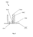
- Fig. 3 illustrates a lighting system 7100 according to the principles of the present invention, including an internal heat transfer member.
- the lighting system includes a base member 7102 adapted to be associated with a conventional light bulb socket (e.g. the socket illustrated in fig. 1 ).
- the lighting system 7100 also includes a housing 7108. Mounted within the housing 7108, resides an LED lighting system including LEDs 7112, a circuit board 7114 and a thermally conductive back plate 7110 (e.g. a metal plate mounted on a circuit board or a metal core circuit board).
- the thermally conductive back plate 7110 is thermally associated with another thermally conductive transfer plate 7104, which is in tum thermally associated with the base member 7102.
- the lighting system 7100 is designed to facilitate the transfer of internally generated heat to an area that is not sensitive to heat loads.
- the LEDs 7112 may generate significant heat but be sensitive to the heat if it is not properly removed from the LEDs.
- the construction illustrated in fig. 3 is provided to illustrate how the heat generated by the LEDs may be passed to the thermally conductive back plate 7110, to the transfer plate 7104 and to the base member 7102. Once the heat is transferred to the base member 7102 it may also be transferred to the inner shell of a socket (e.g. inner shell 7010).
- This system effectively removes heat from a sensitive area of the lighting system (e.g. the LEDs) and transfers it to a less sensitive area and possibly out to an associated lighting fixture (e.g. 7002).
- assemblies 7110 and 7104 may be designed to be a one-piece assembly.
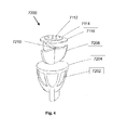
- Fig. 4 illustrates a lighting system 7200 according to another embodiment of the present invention, including a heat sink.
- An LED lighting system similar to the one illustrated in fig. 2 is employed in this embodiment.
- the LED lighting system may include LEDs 7112, a circuit board 7114 and a thermally conductive back plate 7110.
- the thermally conductive back plate may be associated with a thermally conductive heat sink 7208.
- the lighting system may include a housing 7204 with vents 7202 to provide for air flow over the heat sink 7208. As illustrated, the heat would be transferred from the LEDs to the heat sink and the vents would allow for air flow to remove heat from the heat sink.
- the heat sink 7208 may take many forms.
- the housing 7204 may not be vented as the thermal capacity of the heat sink may be adequate to remove the required heat from the lighting system.
- the heat sink may be the housing 7204 itself.
- the back plate 7110 may be associated with a thermally conductive form of housing 7204 with no other internal heat sink required.
- the housing or shell design may be contoured or designed with specific surface treatments to provide for maximum heat transfer.
- Fig. 5 illustrates a lighting system 7300 according to the principles of the present invention, which is associated with a socket heat transfer member 7304.
- the lighting system 7300 is adapted to transfer a significant amount of heat from the internal lighting system to the socket heat transfer member 7304.
- the socket heat transfer member 7304 is thermally associated with plate 7302 (e.g. a thermally conductive portion of a lighting fixture).
- the lighting system 7300 includes a back plate 7110, along with LEDs 7112 and a circuit board 7114 as previously described, and the back plate 7110 passes through the housing and is adapted to make contact with the socket heat transfer member 7302 as the lighting system is screwed into the socket 7118 (which may be similar to previously described socket 7000).
- the heat generated by the lighting system can thus be, in some significant part, transferred to the lighting fixture so it is removed from the more sensitive areas of the lighting system.
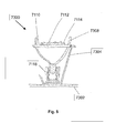
- Fig. 6 illustrates a lighting system 7400 according to the principles of the present invention, which is associated with a flexible thermal transfer member.
- the lighting system 7400 includes a flexible thermal transfer member 7402.
- the flexible thermal transfer member 7402 includes a contact 7408 and a flexible positive load device 7404 (e.g. a spring).
- a socket not shown in this figure
- the back plate 7110 will make contact with the contact 7408 and the contact 7408 will compress the load device 7404 until the lighting system is properly seated in the socket. Lighting system generated heat will then be transferred to the thermal transfer member 7402 and possibly out to another system.
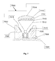
- Fig. 7 illustrates a lighting system 7500 according to the principles of the present invention, including a thermal transfer facility 7502.
- the lighting system 7500 includes an LED light comprising LEDs 7112, a circuit board 7114 and a back plate 7110.
- the back plate 7110 is thermally associated with a thermally conductive housing 7512.
- the housing 7512 is associated with a lens 7514.
- the lighting system is associated with a thermal transfer facility 7502 which includes an inner surface 7518.
- the inner surface 7518 mates, or otherwise becomes thermally associated with, the housing 7512 as the light becomes mechanically associated with the electrical facility (e.g. as the light is screwed into the socket, pressed into the socket, or otherwise engaged).
- the socket may be associated with electrical conductors that pass through the thermal transfer facility 7502 at point 7508.
- the thermal transfer facility 7502 may also include a sensor 7510 to indicate if a lamp is present or not.
- the lighting system e.g. light bulb
- the sensor may indicate to a lighting system processor (not shown in this view but similar to processor 102 of fig. 1 ) that the lighting system is properly engaged with the thermal transfer facility 7502.
- this permits the intelligent regulation of the lighting system.
- a lighting system may operate properly when not associated with a thermal transfer facility 7502, but only when the lighting system is operated at less than optimal power loadings (e.g. 75% of optimal power).
- the processor may decrease the power dissipated by the lighting system. If the sensing system senses that the lighting system is properly associated with the thermal transfer facility 7502, the processor may increase the power dissipated by the lighting system to an intended or optimal power.
- a temperature sensor in the lamp or the socket may be used to determine heat flow of the system and a processor may regulate the power delivered to the lamp for regulation.
- a lighting system is presented that is optimized to operate while associated with a thermal transfer facility 7502 and optimized to operate when not associated with a thermal transfer facility 7502.
- the mechanism for determining the association of the lighting system with the thermal transfer facility 7502 may be manual (e.g. a switch on the side of the lighting system) or automatic (e.g. a sensor system as described above).
- a sensing system may be associated with the lighting system or the thermal transfer facility. If it is associated with the thermal transfer facility, power regulation control may occur outside of the lighting system (e.g. power is turned down outside of the light) or the sensor may transmit a signal to the lighting system (e.g. through the power line, IR, RF, wired or wireless).
- sensor 7510 may be a proximity sensor, ultrasonic sensor, magnetic sensor, electrical sensor, electromechanical sensor, mechanical sensor, or other style and it may be located in the lighting system, in the thermal transfer facility, or otherwise located to perform the intended function.
- the lighting system 7500 may include a thermally conductive material 7520 (e.g. gap pad) positioned between the lamp housing 7512 and the socket surface 7518.
- the thermally conductive material 7520 may be mechanically forgiving such that it compresses while the lamp is seated into the socket to ensure better thermal contact of the lamp to the material to the socket.
- the thermally conductive material 7520 may be attached to the lamp.
- the thermally conductive material 7520 may be attached to the socket.
- a user may place the thermally conductive material 7520 between the lamp and the socket.
- the surface of the lamp and or the surface of the socket may be treated or altered to make the thermal contact between the lamp and socket better.
- the lamp surface may include metal bristles to better mate with the socket surface.
- Fig. 8 illustrates a lighting system 8100 according to the principles of the present invention, which includes a thermally conductive housing 8102.
- the thermally conductive housing 8102 is thermally associated with an LED lighting system 8104.
- the LED lighting system 8104 may be of the kind described herein with respect to other embodiments (e.g. LEDs mounted on a thermally conductive or backed board).
- the thermally conductive housing 8102 may be made of thermally conductive material (e.g. metal or ceramic).
- the housing 8102 may be machined, molded, cast or otherwise formed.
- a lighting system may include active cooling.
- the lighting system may include a fan or other device to actively move air across and or through the lighting system to remove heat.
- the active cooling system may be included as part of a retrofit lighting system.
- the active cooling system may be associated with a lighting fixture meant to house the lighting system.
- a lamp socket may be specifically designed (e.g. with certain compatible mechanical or electrical interfaces) to mate with an LED lighting system.
- such a system may also be designed to permit, or alternatively to prevent (such as to avoid installation of a lighting system that is not electrically compatible with the conventional system), the compatibility with other conventional lighting systems (e.g. incandescent, halogen, fluorescent).
- such a lighting system may be designed to permit, or alternatively to prevent, compatibility with certain sized lights (e.g. higher power consumption lights).
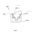
- Fig. 9 illustrates a lighting system 8400 according to the principles of the present invention.
- an LED light 8410 may be closely associated with a socket 8402 through the use of a mechanical facility 8408.
- the mechanical facility 8408 may be a lever, screw, snap connector or other mechanical facility designed to cause a positive mechanical mating of the LED light 8410 and the socket 8402.
- the socket 8402 may be thermally conductive and the housing of the LED light 8410 may also be thermally conductive and the positive mechanical connection between the two surfaces may be designed to promote the thermal transfer of heat from the LED light 8410 to the socket 8402.
- a thermally conductive, malleable material 8404 may be used between the surface of the LED light 8410 and the socket mating surface to increase the surface connection area and to facilitate thermal transfer from the LED light 8410 to the socket 8402.
Abstract
Description
- The present invention relates to the field of lighting systems comprising light emitting diodes and in particular the thermal management of those systems.
-
US2003/0185005A1 discloses a light emitting diode-based light source for retrofitting into a traffic signal lamp that includes at least one light emitting diode (LED), electrical power conditioning electronics, a dispersing reflector cooperating with the at least one LED to adapt light produced by the at least one LED for receipt by optics of the traffic signal lamp, and a screw-type electrical connector adapted to mate with a threaded socket connector of the traffic signal lamp. The screw-type electrical connector is adapted to transmit electrical power to the at least one LED. A heat sinking path is arranged to conduct heat from the LEDs and the electronics into the threaded electrical connector and the threaded socket. - The invention is defined by the independent claim. Embodiments of the invention are defined by the dependent claims.
- An aspect of the present invention relates to the thermal management of a lighting system. In embodiments, a thermal management system may be employed as part of a lighting system to remove heat from heat sensitive portions of the lighting system. In embodiments, the thermal management system may be used in a light bulb, retrofit light bulb, or custom lighting solution. In an embodiment, a lighting system with proper thermal management, may be operated at higher light outputs, achieve greater life times, and or otherwise be improved.
- Semiconductor devices like LED light sources can be damaged by heat. Accordingly, a system may include a thermal facility for removing heat from a lighting unit. The thermal facility may be any facility for managing the flow of heat, such as a convection facility, such as a fan or similar mechanism for providing air flow to the lighting unit, a pump or similar facility for providing flow of a heat-conducting fluid, a vent for allowing flow of air, or any other kind of convection facility. A fan or other convection facility can be under control of a processor and a temperature sensor such as a thermostat to provide cooling when necessary and to remain off when not necessary.
- The thermal facility can be a conduction facility, such as a conducting plate or pad of metal, alloy, or other heat-conducting material, a gap pad between a board bearing light sources and another facility, a thermal conduction path between heat producing elements such as light sources and circuit elements, or a thermal potting facility, such as a polymer for coating heat-producing elements to receive and trap heat away from the light sources. In a preferred embodiment a conductive plate is aluminum or copper. In embodiments a thermal conduction path conducts heat from a circuit board bearing light sources to a housing.
- As used herein for the purposes of the present disclosure, the term "LED" should be understood to include any light emitting diode or other type of carrier injection / junction-based system that is capable of generating radiation in response to an electric signal. Thus, the term LED includes, but is not limited to, various semiconductor-based structures that emit light in response to current, light emitting polymers, light-emitting strips, electro-luminescent strips, and the like.
- In particular, the term LED refers to light emitting diodes of all types (including semi-conductor and organic light emitting diodes) that may be configured to generate radiation in one or more of the infrared spectrum, ultraviolet spectrum, and various portions of the visible spectrum (generally including radiation wavelengths from approximately 400 nanometers to approximately 700 nanometers). Some examples of LEDs include, but are not limited to, various types of infrared LEDs, ultraviolet LEDs, red LEDs, blue LEDs, green LEDs, yellow LEDs, amber LEDs, orange LEDs, and white LEDs (discussed further below). It also should be appreciated that LEDs may be configured to generate radiation having various bandwidths for a given spectrum (e.g. narrow bandwidth, broad bandwidth).
- For example, one implementation of an LED configured to generate essentially white light (e.g. a white LED) may include a number of dies which respectively emit different spectrums of luminescence that, in combination, mix to form essentially white light. In another implementation, a white light LED may be associated with a phosphor material that converts luminescence having a first spectrum to a different second spectrum. In one example of this implementation, luminescence having a relatively short wavelength and narrow bandwidth spectrum "pumps" the phosphor material, which in turn radiates longer wavelength radiation having a somewhat broader spectrum.
- It should also be understood that the term LED does not limit the physical and/or electrical package type of an LED. For example, as discussed above, an LED may refer to a single light emitting device having multiple dies that are configured to respectively emit different spectrums of radiation (e.g. that may or may not be individually controllable). Also, an LED may be associated with a phosphor that is considered as an integral part of the LED (e.g. some types of white LEDs). In general, the term LED may refer to packaged LEDs, non-packaged LEDs, surface mount LEDs, chip-on-board LEDs, radial package LEDs, power package LEDs, LEDs including some type of encasement and/or optical element (e.g. a diffusing lens), etc.
-
-
Fig. 1 illustrates one example of a lighting unit that may serve as a device in a lighting environment according to one embodiment of the present invention. -
Fig. 2 illustrates a portion of a conventional Edison style light bulb socket. -
Fig. 3 illustrates a lighting system according to the principles of the present invention, including an internal heat transfer member. -
Fig. 4 illustrates another embodiment of the present invention, including a heat sink. -
Fig. 5 illustrates a lighting system according to the principles of the present invention, which is associated with a socket heat transfer member. -
Fig. 6 illustrates a lighting system according to the principles of the present invention, which is associated with a flexible thermal transfer member. -
Fig. 7 illustrates a lighting system according to the principles of the present invention, including a thermal transfer facility. -
Fig. 8 illustrates a lighting system which includes a thermallyconductive housing 8102 according to the principles of the present invention. -
Fig. 9 illustrates a lighting system according to the principles of the present invention - Various embodiments of the present invention are described below, including certain embodiments relating particularly to LED-based light sources.
-
Fig. 1 illustrates one example of alighting unit 100 that may serve as a device in a lighting environment according to one embodiment of the present invention. Some examples of LED-based lighting units similar to those that are described below in connection withFig. 1 may be found, for example, inUS6,016,038 andUS6,211,626 . - In various embodiments of the present invention, the
lighting unit 100 shown inFig. 1 may be used alone or together with other similar lighting units in a system of lighting units. Used alone or in combination with other lighting units, thelighting unit 100 may be employed in a variety of applications including, but not limited to, interior or exterior space illumination in general, direct or indirect illumination of objects or spaces, theatrical or other entertainment-based / special effects illumination, decorative illumination, safety oriented illumination, vehicular illumination, illumination of displays and/or merchandise (e.g. for advertising and/or in retail/consumer environments), combined illumination and communication systems, etc., as well as for various indication and informational purposes. - Additionally, one or more lighting units similar to that described in connection with
Fig. 1 may be implemented in a variety of products including, but not limited to, various forms of light modules or bulbs having various shapes and electrical/mechanical coupling arrangements (including replacement or "retrofit" modules or bulbs adapted for use in conventional sockets or fixtures), as well as a variety of consumer and/or household products (e.g. night lights, toys, games or game components, entertainment components or systems, utensils, appliances, kitchen aids, cleaning products, etc.). - In one embodiment, the
lighting unit 100 shown inFig. 1 may include one ormore light sources light sources Fig. 1 shows fourlight sources lighting unit 100, as discussed further below. - As shown in
Fig. 1 , thelighting unit 100 also may include aprocessor 102 that is configured to output one or more control signals to drive thelight sources processor 102 may be configured to output at least one control signal for each light source so as to independently control the intensity of light generated by each light source. Some examples of control signals that may be generated by the processor to control the light sources include, but are not limited to, pulse modulated signals, pulse width modulated signals (PWM), pulse amplitude modulated signals (PAM), pulse displacement modulated signals, analog control signals (e.g. current control signals, voltage control signals), combinations and/or modulations of the foregoing signals, or other control signals. - In one aspect, the
processor 102 may control other dedicated circuitry (not shown inFig. 1 ), which in tum controls the light sources so as to vary their respective intensities. Lighting systems in accordance with this specification can operate LEDs in an efficient manner. Typical LED performance characteristics depend on the amount of current drawn by the LED. The optimal efficacy may be obtained at a lower current than the level where maximum brightness occurs. LEDs are typically driven well above their most efficient operating current to increase the brightness delivered by the LED while maintaining a reasonable life expectancy. As a result, increased efficacy can be provided when the maximum current value of the PWM signal may be variable. For example, if the desired light output is less than the maximum required output the current maximum and/or the PWM signal width may be reduced. This may result in pulse amplitude modulation (PAM), for example. However, the width and amplitude of the current used to drive the LED may be varied to optimize the LED performance. In an embodiment, a lighting system may also be adapted to provide only amplitude control of the current through the LED. While many of the embodiments provided herein describe the use of PWM and PAM to drive the LEDs, one skilled in the art would appreciate that there are many techniques to accomplish the LED control described herein and, as such, the scope of the present invention is not limited by anyone control technique. In embodiments, it is possible to use other techniques, such as pulse frequency modulation (PFM), or pulse displacement modulation (PDM), such as in combination with either or both of PWM and PAM. - Pulse width modulation (PWM) involves supplying a substantially constant current to the LEDs for particular periods of time. The shorter the time, or pulse-width, the less brightness an observer will observe in the resulting light. The human eye integrates the light it receives over a period of time and, even though the current through the LED may generate the same light level regardless of pulse duration, the eye will perceive short pulses as "dimmer" than longer pulses. The PWM technique is considered one of the preferred techniques for driving LEDs, although the present invention is not limited to such control techniques. When two or more colored LEDs are provided in a lighting system, the colors may be mixed and many variations of colors can be generated by changing the intensity, or perceived intensity, of the LEDs. In an embodiment, three colors of LEDs are presented (e.g. red, green and blue) and each of the colors is driven with PWM to vary its apparent intensity. This system allows for the generation of millions of colors (e.g. 16.7 million colors when 8-bit control is used on each of the PWM channels).
- In an embodiment the LEDs are modulated with PWM as well as modulating the amplitude of the current driving the LEDs (Pulse Amplitude Modulation, or PAM).
- In one embodiment of the
lighting unit 100, one or more of thelight sources Fig. 1 may include a group of multiple LEDs or other types of light sources (e.g. various parallel and/or serial connections of LEDs or other types of light sources) that are controlled together by theprocessor 102. Additionally, it should be appreciated that one or more of thelight sources - In another aspect of the
lighting unit 100 shown inFig. 1 , thelighting unit 100 may be constructed and arranged to produce a wide range of variable color radiation. For example, thelighting unit 100 may be particularly arranged such that the processor controlled variable intensity light generated by two or more of the light sources combines to produce a mixed colored light (including essentially white light having a variety of color temperatures). In particular, the color (or color temperature) of the mixed colored light may be varied by varying one or more of the respective intensities of the light sources (e.g. in response to one or more control signals output by the processor 102). - Furthermore, the
processor 102 may be particularly configured (e.g. programmed) to provide control signals to one or more of the light sources so as to generate a variety of static or time-varying (dynamic) multi-color (or multi-color temperature) lighting effects. As shown inFig. 1 , thelighting unit 100 also may include amemory 114 to store various information. For example, thememory 114 may be employed to store one or more lighting programs for execution by the processor 102 (e.g. to generate one or more control signals for the light sources), as well as various types of data useful for generating variable color radiation (e.g. calibration information, discussed further below). Thememory 114 also may store one or more particular identifiers (e.g. a serial number, an address, etc.) that may be used either locally or on a system level to identify thelighting unit 100. In various embodiments, such identifiers may be pre-programmed by a manufacturer, for example, and may be either alterable or non-alterable thereafter (e.g. via some type of user interface located on the lighting unit, via one or more data or control signals received by the lighting unit, etc.). Alternatively, such identifiers may be determined at the time of initial use of the lighting unit in the field, and again may be alterable or non-alterable thereafter. - In another aspect, as also shown in
Fig. 1 , thelighting unit 100 optionally may include one ormore user interfaces 118 that are provided to facilitate any of a number of user-selectable settings or functions (e.g. generally controlling the light output of thelighting unit 100, changing and/or selecting various pre-programmed lighting effects to be generated by the lighting unit, changing and/or selecting various parameters of selected lighting effects, setting particular identifiers such as addresses or serial numbers for the lighting unit, etc.). In various embodiments, the communication between theuser interface 118 and the lighting unit may be accomplished through wire or cable, or wireless transmission. In one implementation, theprocessor 102 of the lighting unit monitors theuser interface 118 and controls one or more of thelight sources processor 102 may be configured to respond to operation of the user interface by originating one or more control signals for controlling one or more of the light sources. Alternatively, theprocessor 102 may be configured to respond by selecting one or more pre-programmed control signals stored in memory, modifying control signals generated by executing a lighting program, selecting and executing a new lighting program from memory, or otherwise affecting the radiation generated by one or more of the light sources. -
Fig. 1 also illustrates that thelighting unit 100 may be configured to receive one ormore signals 122 from one or moreother signal sources 124. In one implementation, theprocessor 102 of the lighting unit may use the signal(s) 122, either alone or in combination with other control signals (e.g. signals generated by executing a lighting program, one or more outputs from a user interface, etc.), so as to control one or more of the light sources 104 (104A, 104B, 104C and 104D) in a manner similar to that discussed above in connection with the user interface. Examples of the signal(s) 122 that may be received and processed by theprocessor 102 include, but are not limited to, one or more audio signals, video signals, power signals, various types of data signals, signals representing information obtained from a network (e.g. the Internet), signals representing some detectable/sensed condition, signals from lighting units, signals consisting of modulated light, etc. In various implementations, the signal source(s) 124 may be located remotely from thelighting unit 100, or included as a component of the lighting unit. For example, in one embodiment, a signal from onelighting unit 100 could be sent over a network to anotherlighting unit 100. - Some examples of a
signal source 124 that may be employed in, or used in connection with, thelighting unit 100 ofFig. 1 include any of a variety of sensors or transducers that generate one ormore signals 122 in response to some stimulus. Examples of such sensors include, but are not limited to, various types of environmental condition sensors, such as thermally sensitive (e.g. temperature, infrared) sensors, humidity sensors, motion sensors, photo sensors/light sensors (e.g. sensors that are sensitive to one or more particular spectra of electromagnetic radiation), sound or vibration sensors or other pressure/force transducers (e.g. microphones, piezoelectric devices), and the like. - Additional examples of a
signal source 124 include various metering/detection devices that monitor electrical signals or characteristics (e.g. voltage, current, power, resistance, capacitance, inductance, etc.) or chemical/biological characteristics (e.g. acidity, a presence of one or more particular chemical or biological agents, bacteria, etc.) and provide one ormore signals 122 based on measured values of the signals or characteristics. Yet other examples of asignal source 124 include various types of scanners, image recognition systems, voice or other sound recognition systems, artificial intelligence and robotics systems, and the like. - A
signal source 124 could also be alighting unit 100, aprocessor 102, or anyone of many available signal generating devices, such as media players, MP3 players, computers, DVD players, CD players, television signal sources, camera signal sources, microphones, speakers, telephones, cellular phones, instant messenger devices, SMS devices, wireless devices, personal organizer devices, and many others. - In one embodiment, the
lighting unit 100 shown inFig. 1 also may include one or moreoptical facilities 130 to optically process the radiation generated by thelight sources optical facilities 130 may be particularly configured to variably change one or both of a spatial distribution and a propagation direction of the generated radiation (e.g. in response to some electrical and/or mechanical stimulus). Examples of optical facilities that may be included in thelighting unit 100 include, but are not limited to, reflective materials, refractive materials, translucent materials, filters, lenses, mirrors, and fiber optics. Theoptical facility 130 also may include a phosphorescent material, luminescent material, or other material capable of responding to or interacting with the generated radiation. - As also shown in
Fig. 1 , thelighting unit 100 may include one ormore communication ports 120 to facilitate coupling of thelighting unit 100 to any of a variety of other devices. For example, one ormore communication ports 120 may facilitate coupling multiple lighting units together as a networked lighting system, in which at least some of the lighting units are addressable (e.g. have particular identifiers or addresses) and are responsive to particular data transported across the network. In particular, in a networked lighting system environment, as data is communicated via the network, theprocessor 102 of each lighting unit coupled to the network may be configured to be responsive to particular data (e.g. lighting control commands) that pertain to it (e.g. in some cases, as dictated by the respective identifiers of the networked lighting units). Once a given processor identifies particular data intended for it, it may read the data and, for example, change the lighting conditions produced by its light sources according to the received data (e.g. by generating appropriate control signals to the light sources). In one aspect, thememory 114 of each lighting unit coupled to the network may be loaded, for example, with a table of lighting control signals that correspond with data theprocessor 102 receives. Once theprocessor 102 receives data from the network, the processor may consult the table to select the control signals that correspond to the received data, and control the light sources of the lighting unit accordingly. - In one aspect of this embodiment, the
processor 102 of a given lighting unit, whether or not coupled to a network, may be configured to interpret lighting instructions/data that are received in a DMX protocol (as discussed, for example, inU.S. Patents 6,016,038 and6,211,626 ), which is a lighting command protocol conventionally employed in the lighting industry for some programmable lighting applications. - However, it should be appreciated that lighting units suitable for purposes of the present invention are not limited in this respect, as lighting units according to various embodiments may be configured to be responsive to other types of communication protocols so as to control their respective light sources.
- In one embodiment, the
lighting unit 100 ofFig. 1 may include and/or be coupled to one ormore power sources 108. In various aspects, examples of power source(s) 108 include, but are not limited to, AC power sources, DC power sources, batteries, solar based power sources, thermoelectric or mechanical-based power sources and the like. Additionally, in one aspect, the power source(s) 108 may include or be associated with one or more power conversion devices that convert power received by an external power source to a form suitable for operation of thelighting unit 100. - While not shown explicitly in
Fig. 1 , thelighting unit 100 may be implemented in anyone of several different structural configurations according to various embodiments of the present invention. For example, a given lighting unit may have anyone of a variety of mounting arrangements for the light source(s), enclosure/housing arrangements and shapes to partially or fully enclose the light sources, and/or electrical and mechanical connection configurations. In particular, a lighting unit may be configured as a replacement or "retrofit" to engage electrically and mechanically in a conventional socket or fixture arrangement (e.g. an Edison-type screw socket, a halogen fixture arrangement, a fluorescent fixture arrangement, etc.). - Additionally, one or more optical facilities as discussed above may be partially or fully integrated with an enclosure/housing arrangement for the lighting unit. Furthermore, a given lighting unit optionally may be associated with (e.g. include, be coupled to and/or packaged together with) various other components (e.g. control circuitry such as the processor and/or memory, one or more sensors/transducers/signal sources, user interfaces, displays, power sources, power conversion devices, etc.) relating to the operation of the light source(s).
-
Fig. 2 illustrates a portion of a conventional Edison stylelight bulb socket 7000. The socket includes anouter portion 7008, typically plastic, ceramic or other electrically insulating material. Generally mounted in the outer portion resides aninner shell 7010 that is attached to theouter portion 7008 by afastener 7012. The shell is typically connected to an electrically conductive member 7004 (e.g. a wire) to electrically energize the shell to facilitate the transfer of power to an associated light bulb (not shown in this figure). Thesocket 7000 may also be mounted to a plate, fixture, or other platform throughfastener 7014. As will be appreciated by one skilled in the art, an associated bulb would screw into a socket of this type and thesocket 7000 would be associated with a lighting fixture orplatform 7002. The heat generated by a conventional light bulb would partially be transmitted to thesocket 7000 through theinner shell 7010 and pass through thewire 7004 and to the outer portion and eventually to theplatform 7002 itself. - While many of the embodiments herein are described in connection with screw bases and sockets, it should be understood that the base / socket connection may be any number of mechanical and or electrical interfaces designed to accomplish the objective. In an embodiment, this base / socket interface may be a simple set of conductors (e.g. wires).
- Applicants recognized and appreciated that it would be useful to design a lighting system that transfers more of its generated heat to a socket and or platform to reduce the heat trapped in the lighting system itself. In embodiments, a lighting system is designed to transfer the heat through a conventional lighting socket (e.g. socket 7000). In embodiments, a lighting system is designed to transfer its generated heat more directly to a platform or
fixture 7002 associated with the lighting system. In embodiments, a lighting system is designed to transfer its heat from more sensitive portions of the lighting system to areas that are less sensitive. In embodiments, the lighting system is an LED based lighting system. -
Fig. 3 illustrates alighting system 7100 according to the principles of the present invention, including an internal heat transfer member. The lighting system includes abase member 7102 adapted to be associated with a conventional light bulb socket (e.g. the socket illustrated infig. 1 ). Thelighting system 7100 also includes ahousing 7108. Mounted within thehousing 7108, resides an LED lightingsystem including LEDs 7112, acircuit board 7114 and a thermally conductive back plate 7110 (e.g. a metal plate mounted on a circuit board or a metal core circuit board). The thermallyconductive back plate 7110 is thermally associated with another thermallyconductive transfer plate 7104, which is in tum thermally associated with thebase member 7102. Thelighting system 7100 is designed to facilitate the transfer of internally generated heat to an area that is not sensitive to heat loads. For example, theLEDs 7112 may generate significant heat but be sensitive to the heat if it is not properly removed from the LEDs. The construction illustrated infig. 3 is provided to illustrate how the heat generated by the LEDs may be passed to the thermallyconductive back plate 7110, to thetransfer plate 7104 and to thebase member 7102. Once the heat is transferred to thebase member 7102 it may also be transferred to the inner shell of a socket (e.g. inner shell 7010). This system effectively removes heat from a sensitive area of the lighting system (e.g. the LEDs) and transfers it to a less sensitive area and possibly out to an associated lighting fixture (e.g. 7002). In an embodiment,assemblies -
Fig. 4 illustrates alighting system 7200 according to another embodiment of the present invention, including a heat sink. An LED lighting system similar to the one illustrated infig. 2 is employed in this embodiment. The LED lighting system may includeLEDs 7112, acircuit board 7114 and a thermallyconductive back plate 7110. The thermally conductive back plate may be associated with a thermallyconductive heat sink 7208. The lighting system may include ahousing 7204 withvents 7202 to provide for air flow over theheat sink 7208. As illustrated, the heat would be transferred from the LEDs to the heat sink and the vents would allow for air flow to remove heat from the heat sink. One skilled in the art would appreciate that theheat sink 7208 may take many forms. In embodiments, thehousing 7204 may not be vented as the thermal capacity of the heat sink may be adequate to remove the required heat from the lighting system. In embodiments, the heat sink may be thehousing 7204 itself. Theback plate 7110 may be associated with a thermally conductive form ofhousing 7204 with no other internal heat sink required. In an embodiment, the housing or shell design may be contoured or designed with specific surface treatments to provide for maximum heat transfer. -
Fig. 5 illustrates alighting system 7300 according to the principles of the present invention, which is associated with a socketheat transfer member 7304. Thelighting system 7300 is adapted to transfer a significant amount of heat from the internal lighting system to the socketheat transfer member 7304. The socketheat transfer member 7304 is thermally associated with plate 7302 (e.g. a thermally conductive portion of a lighting fixture). Thelighting system 7300 includes aback plate 7110, along withLEDs 7112 and acircuit board 7114 as previously described, and theback plate 7110 passes through the housing and is adapted to make contact with the socketheat transfer member 7302 as the lighting system is screwed into the socket 7118 (which may be similar to previously described socket 7000). The heat generated by the lighting system can thus be, in some significant part, transferred to the lighting fixture so it is removed from the more sensitive areas of the lighting system. -
Fig. 6 illustrates alighting system 7400 according to the principles of the present invention, which is associated with a flexible thermal transfer member. Thelighting system 7400 includes a flexiblethermal transfer member 7402. The flexiblethermal transfer member 7402 includes acontact 7408 and a flexible positive load device 7404 (e.g. a spring). As the lighting system is screwed into a socket (not shown in this figure), theback plate 7110 will make contact with thecontact 7408 and thecontact 7408 will compress theload device 7404 until the lighting system is properly seated in the socket. Lighting system generated heat will then be transferred to thethermal transfer member 7402 and possibly out to another system. -
Fig. 7 illustrates alighting system 7500 according to the principles of the present invention, including athermal transfer facility 7502. Thelighting system 7500 includes an LEDlight comprising LEDs 7112, acircuit board 7114 and aback plate 7110. Theback plate 7110 is thermally associated with a thermallyconductive housing 7512. Thehousing 7512 is associated with alens 7514. The lighting system is associated with athermal transfer facility 7502 which includes aninner surface 7518. Theinner surface 7518 mates, or otherwise becomes thermally associated with, thehousing 7512 as the light becomes mechanically associated with the electrical facility (e.g. as the light is screwed into the socket, pressed into the socket, or otherwise engaged). The socket may be associated with electrical conductors that pass through thethermal transfer facility 7502 atpoint 7508. - The
thermal transfer facility 7502 may also include asensor 7510 to indicate if a lamp is present or not. The lighting system (e.g. light bulb) may include such a sensor (not shown) as well or in place of one in the thermal transfer facility. The sensor may indicate to a lighting system processor (not shown in this view but similar toprocessor 102 offig. 1 ) that the lighting system is properly engaged with thethermal transfer facility 7502. In embodiments, this permits the intelligent regulation of the lighting system. For example, a lighting system may operate properly when not associated with athermal transfer facility 7502, but only when the lighting system is operated at less than optimal power loadings (e.g. 75% of optimal power). If the sensing system senses that the lighting system is not properly associated with thethermal transfer facility 7502, the processor may decrease the power dissipated by the lighting system. If the sensing system senses that the lighting system is properly associated with thethermal transfer facility 7502, the processor may increase the power dissipated by the lighting system to an intended or optimal power. A temperature sensor in the lamp or the socket may be used to determine heat flow of the system and a processor may regulate the power delivered to the lamp for regulation. - In embodiments, a lighting system is presented that is optimized to operate while associated with a
thermal transfer facility 7502 and optimized to operate when not associated with athermal transfer facility 7502. The mechanism for determining the association of the lighting system with thethermal transfer facility 7502 may be manual (e.g. a switch on the side of the lighting system) or automatic (e.g. a sensor system as described above). As indicated above, a sensing system may be associated with the lighting system or the thermal transfer facility. If it is associated with the thermal transfer facility, power regulation control may occur outside of the lighting system (e.g. power is turned down outside of the light) or the sensor may transmit a signal to the lighting system (e.g. through the power line, IR, RF, wired or wireless). - In embodiments,
sensor 7510 may be a proximity sensor, ultrasonic sensor, magnetic sensor, electrical sensor, electromechanical sensor, mechanical sensor, or other style and it may be located in the lighting system, in the thermal transfer facility, or otherwise located to perform the intended function. - In embodiments, the
lighting system 7500 may include a thermally conductive material 7520 (e.g. gap pad) positioned between thelamp housing 7512 and thesocket surface 7518. The thermallyconductive material 7520 may be mechanically forgiving such that it compresses while the lamp is seated into the socket to ensure better thermal contact of the lamp to the material to the socket. In an embodiment, the thermallyconductive material 7520 may be attached to the lamp. In an embodiment, the thermallyconductive material 7520 may be attached to the socket. In an embodiment, a user may place the thermallyconductive material 7520 between the lamp and the socket. In an embodiment, the surface of the lamp and or the surface of the socket may be treated or altered to make the thermal contact between the lamp and socket better. For example, the lamp surface may include metal bristles to better mate with the socket surface. -
Fig. 8 illustrates alighting system 8100 according to the principles of the present invention, which includes a thermallyconductive housing 8102. In embodiments, the thermallyconductive housing 8102 is thermally associated with anLED lighting system 8104. TheLED lighting system 8104 may be of the kind described herein with respect to other embodiments (e.g. LEDs mounted on a thermally conductive or backed board). In embodiments, the thermallyconductive housing 8102 may be made of thermally conductive material (e.g. metal or ceramic). In embodiments, thehousing 8102 may be machined, molded, cast or otherwise formed. - While many of the embodiments herein describe passive thermal management systems and methods, a lighting system according to the principles of the present invention may include active cooling. For example, the lighting system may include a fan or other device to actively move air across and or through the lighting system to remove heat. In an embodiment, the active cooling system may be included as part of a retrofit lighting system. In an embodiment, the active cooling system may be associated with a lighting fixture meant to house the lighting system.
- A lamp socket may be specifically designed (e.g. with certain compatible mechanical or electrical interfaces) to mate with an LED lighting system. In an embodiment, such a system may also be designed to permit, or alternatively to prevent (such as to avoid installation of a lighting system that is not electrically compatible with the conventional system), the compatibility with other conventional lighting systems (e.g. incandescent, halogen, fluorescent). In an embodiment, such a lighting system may be designed to permit, or alternatively to prevent, compatibility with certain sized lights (e.g. higher power consumption lights).
-
Fig. 9 illustrates alighting system 8400 according to the principles of the present invention. In an embodiment, anLED light 8410 may be closely associated with asocket 8402 through the use of amechanical facility 8408. Themechanical facility 8408 may be a lever, screw, snap connector or other mechanical facility designed to cause a positive mechanical mating of theLED light 8410 and thesocket 8402. Thesocket 8402 may be thermally conductive and the housing of theLED light 8410 may also be thermally conductive and the positive mechanical connection between the two surfaces may be designed to promote the thermal transfer of heat from theLED light 8410 to thesocket 8402. In an embodiment, a thermally conductive,malleable material 8404 may be used between the surface of theLED light 8410 and the socket mating surface to increase the surface connection area and to facilitate thermal transfer from theLED light 8410 to thesocket 8402.
Claims (11)
- A lighting system (7500) comprising an electrical facility for powering a LED light, the LED light comprising LEDs (7112), a circuit board (7114) and a back plate (7110), wherein the back plate (7110) is thermally associated with a thermally conductive housing (7518) and wherein an inner surface (7518) of a thermal transfer facility (7502) is thermally associated with the thermally conductive housing (7512) when the LED light is associated with the electrical facility.
- The lighting system as claimed in claim 1, further comprising a thermally conductive material (7520) positioned between the housing (7512) and the inner surface of the thermal transfer facility (7508).
- The lighting system as claimed in claim 2, wherein the thermally conductive material (7520) is compressable.
- The lighting system as claimed in any one of the previous claims, wherein the thermal transfer facility (7502) is a socket.
- The lighting system as claimed in claim 4, further comprising a mechanical facility (8408) designed to cause a positive mechanical mating of the housing and the socket and wherein the positive mechanical connection between the two surfaces is designed to promote the thermal transfer of heat from the housing (8410) to the socket (8402).
- The lighting system according to claim 5, wherein the mechanical facility comprises a lever, a screw, or a snap connector.
- The lighting system as claimed in claim 4, wherein the surface of the housing comprises metal bristles.
- The lighting system as claimed in claim 1, wherein the thermal transfer facility (7502) comprises a sensor (7510) for sensing if the thermal transfer facility (7502) is properly thermally associated with the thermally conductive housing (7512).
- The lighting system as claimed in claim 8, further comprising a processor for regulating the power delivered to the LED light in dependence of an indication of the sensor (7510) on the proper engagement of the thermal transfer facility (7502) with the thermally conductive housing (7512).
- The lighting system as claimed in claim 9, wherein the processor is adapted for decreasing the power delivered to the LED light when the thermal transfer facility (7502) is not properly thermally associated with the thermally conductive housing (7512) and for increasing the power delivered to the LED light to an intended or optimum power when the thermal transfer facility (7502) is properly thermally associated with the thermally conductive housing (7512).
- The lighting system as claimed in any of the previous claims, further comprising a fan or other device to actively move air across and or through the lighting system to remove heat.
Applications Claiming Priority (4)
| Application Number | Priority Date | Filing Date | Title |
|---|---|---|---|
| US52884703P | 2003-12-11 | 2003-12-11 | |
| US55840004P | 2004-03-31 | 2004-03-31 | |
| US58809004P | 2004-07-15 | 2004-07-15 | |
| EP04813843A EP1704752A4 (en) | 2003-12-11 | 2004-12-13 | Thermal management methods and apparatus for lighting devices |
Related Parent Applications (2)
| Application Number | Title | Priority Date | Filing Date |
|---|---|---|---|
| EP04813843.2 Division | 2004-12-13 | ||
| EP04813843A Division EP1704752A4 (en) | 2003-12-11 | 2004-12-13 | Thermal management methods and apparatus for lighting devices |
Publications (2)
| Publication Number | Publication Date |
|---|---|
| EP2572932A1 true EP2572932A1 (en) | 2013-03-27 |
| EP2572932B1 EP2572932B1 (en) | 2015-04-22 |
Family
ID=34705095
Family Applications (2)
| Application Number | Title | Priority Date | Filing Date |
|---|---|---|---|
| EP20120198393 Active EP2572932B1 (en) | 2003-12-11 | 2004-12-13 | Thermal management for lighting devices |
| EP04813843A Ceased EP1704752A4 (en) | 2003-12-11 | 2004-12-13 | Thermal management methods and apparatus for lighting devices |
Family Applications After (1)
| Application Number | Title | Priority Date | Filing Date |
|---|---|---|---|
| EP04813843A Ceased EP1704752A4 (en) | 2003-12-11 | 2004-12-13 | Thermal management methods and apparatus for lighting devices |
Country Status (6)
| Country | Link |
|---|---|
| US (1) | US7344279B2 (en) |
| EP (2) | EP2572932B1 (en) |
| KR (2) | KR20080099352A (en) |
| AU (1) | AU2004300444B2 (en) |
| CA (1) | CA2552683C (en) |
| WO (1) | WO2005060309A2 (en) |
Families Citing this family (577)
| Publication number | Priority date | Publication date | Assignee | Title |
|---|---|---|---|---|
| US7139617B1 (en) | 1999-07-14 | 2006-11-21 | Color Kinetics Incorporated | Systems and methods for authoring lighting sequences |
| US7233831B2 (en) | 1999-07-14 | 2007-06-19 | Color Kinetics Incorporated | Systems and methods for controlling programmable lighting systems |
| US20020176259A1 (en) | 1999-11-18 | 2002-11-28 | Ducharme Alfred D. | Systems and methods for converting illumination |
| US7364488B2 (en) | 2002-04-26 | 2008-04-29 | Philips Solid State Lighting Solutions, Inc. | Methods and apparatus for enhancing inflatable devices |
| EP1512312A4 (en) | 2002-05-13 | 2006-11-22 | Johnson & Son Inc S C | Coordinated emission of fragrance, light, and sound |
| US7204622B2 (en) | 2002-08-28 | 2007-04-17 | Color Kinetics Incorporated | Methods and systems for illuminating environments |
| US7615939B2 (en) * | 2003-03-17 | 2009-11-10 | C&D Zodiac, Inc. | Spectrally calibratable multi-element RGB LED light source |
| EP1687692B1 (en) * | 2003-11-20 | 2010-04-28 | Philips Solid-State Lighting Solutions, Inc. | Light system manager |
| WO2011143510A1 (en) | 2010-05-12 | 2011-11-17 | Lynk Labs, Inc. | Led lighting system |
| US10575376B2 (en) | 2004-02-25 | 2020-02-25 | Lynk Labs, Inc. | AC light emitting diode and AC LED drive methods and apparatus |
| US10499465B2 (en) | 2004-02-25 | 2019-12-03 | Lynk Labs, Inc. | High frequency multi-voltage and multi-brightness LED lighting devices and systems and methods of using same |
| US20060221606A1 (en) * | 2004-03-15 | 2006-10-05 | Color Kinetics Incorporated | Led-based lighting retrofit subassembly apparatus |
| CA2730210C (en) * | 2004-03-15 | 2015-05-05 | Philips Solid-State Lighting Solutions, Inc. | Power control methods and apparatus |
| US7515128B2 (en) * | 2004-03-15 | 2009-04-07 | Philips Solid-State Lighting Solutions, Inc. | Methods and apparatus for providing luminance compensation |
| WO2005089293A2 (en) * | 2004-03-15 | 2005-09-29 | Color Kinetics Incorporated | Methods and systems for providing lighting systems |
| WO2006023149A2 (en) * | 2004-07-08 | 2006-03-02 | Color Kinetics Incorporated | Led package methods and systems |
| WO2006031810A2 (en) * | 2004-09-10 | 2006-03-23 | Color Kinetics Incorporated | Power control methods and apparatus for variable loads |
| DE102004047766C5 (en) * | 2004-09-30 | 2014-02-27 | Osram Opto Semiconductors Gmbh | lighting device |
| KR100638047B1 (en) * | 2004-10-15 | 2006-10-23 | 엘지전자 주식회사 | Liquid crystal display having back light unit |
| DE102005063433B4 (en) * | 2004-10-29 | 2009-11-26 | Lg Display Co., Ltd. | Backlight unit and liquid crystal display device |
| US7710369B2 (en) * | 2004-12-20 | 2010-05-04 | Philips Solid-State Lighting Solutions, Inc. | Color management methods and apparatus for lighting devices |
| US9070850B2 (en) | 2007-10-31 | 2015-06-30 | Cree, Inc. | Light emitting diode package and method for fabricating same |
| US9793247B2 (en) | 2005-01-10 | 2017-10-17 | Cree, Inc. | Solid state lighting component |
| US7821023B2 (en) | 2005-01-10 | 2010-10-26 | Cree, Inc. | Solid state lighting component |
| WO2006081186A2 (en) | 2005-01-24 | 2006-08-03 | Color Kinetics Incorporated | Methods and apparatus for providing workspace lighting and facilitating workspace customization |
| US20060193131A1 (en) * | 2005-02-28 | 2006-08-31 | Mcgrath William R | Circuit devices which include light emitting diodes, assemblies which include such circuit devices, and methods for directly replacing fluorescent tubes |
| JP4218677B2 (en) * | 2005-03-08 | 2009-02-04 | セイコーエプソン株式会社 | Microchannel structure and manufacturing method thereof, light source device, and projector |
| WO2006119582A1 (en) * | 2005-05-13 | 2006-11-16 | Tama Berkeljon | Lighting apparatus |
| US7445340B2 (en) * | 2005-05-19 | 2008-11-04 | 3M Innovative Properties Company | Polarized, LED-based illumination source |
| US8061865B2 (en) | 2005-05-23 | 2011-11-22 | Philips Solid-State Lighting Solutions, Inc. | Methods and apparatus for providing lighting via a grid system of a suspended ceiling |
| US7703951B2 (en) * | 2005-05-23 | 2010-04-27 | Philips Solid-State Lighting Solutions, Inc. | Modular LED-based lighting fixtures having socket engagement features |
| US7766518B2 (en) | 2005-05-23 | 2010-08-03 | Philips Solid-State Lighting Solutions, Inc. | LED-based light-generating modules for socket engagement, and methods of assembling, installing and removing same |
| KR100699149B1 (en) * | 2005-05-24 | 2007-03-22 | 엘지전자 주식회사 | Auto door mechanism for a projector |
| US7777427B2 (en) | 2005-06-06 | 2010-08-17 | Philips Solid-State Lighting Solutions, Inc. | Methods and apparatus for implementing power cycle control of lighting devices based on network protocols |
| KR100713536B1 (en) * | 2005-06-07 | 2007-04-30 | 삼성전자주식회사 | FlEXIBLE PRINTED CIRCUIT BOARD FOR ELECTRONIC EQUIPMENT |
| US9412926B2 (en) | 2005-06-10 | 2016-08-09 | Cree, Inc. | High power solid-state lamp |
| KR101177572B1 (en) * | 2005-09-26 | 2012-08-27 | 엘지디스플레이 주식회사 | Light Emitting Diode and Liquid Crystal Module Using The Same |
| US8100567B2 (en) * | 2005-10-19 | 2012-01-24 | Rambus International Ltd. | Light-emitting devices and related systems |
| US7479660B2 (en) * | 2005-10-21 | 2009-01-20 | Perkinelmer Elcos Gmbh | Multichip on-board LED illumination device |
| US20070103934A1 (en) * | 2005-11-10 | 2007-05-10 | Keh Kean L | System and method for constructing a backlighted display using dynamically optimized light source |
| US7309152B2 (en) * | 2005-11-23 | 2007-12-18 | Unity Opto Technology Co., Ltd. | Light source structure of backlight module |
| US8465175B2 (en) * | 2005-11-29 | 2013-06-18 | GE Lighting Solutions, LLC | LED lighting assemblies with thermal overmolding |
| TWI433588B (en) | 2005-12-13 | 2014-04-01 | Koninkl Philips Electronics Nv | Led lighting device |
| TWI298410B (en) * | 2005-12-23 | 2008-07-01 | Au Optronics Corp | Backlight module |
| US7619370B2 (en) * | 2006-01-03 | 2009-11-17 | Philips Solid-State Lighting Solutions, Inc. | Power allocation methods for lighting devices having multiple source spectrums, and apparatus employing same |
| US20070211182A1 (en) * | 2006-03-10 | 2007-09-13 | Luminus Devices, Inc. | Optical system thermal management methods and systems |
| US20070211183A1 (en) * | 2006-03-10 | 2007-09-13 | Luminus Devices, Inc. | LCD thermal management methods and systems |
| US20070211184A1 (en) * | 2006-03-10 | 2007-09-13 | Luminus Devices, Inc. | Liquid crystal display systems including LEDs |
| JP4139856B2 (en) * | 2006-03-22 | 2008-08-27 | 八洲電業株式会社 | Fluorescent lamp type LED lighting tube |
| US7806574B2 (en) * | 2006-04-16 | 2010-10-05 | Albeo Technologies, Inc. | Thermal management of LED-based lighting systems |
| US8425085B2 (en) * | 2006-04-16 | 2013-04-23 | Albeo Technologies, Inc. | Thermal management of LED-based lighting systems |
| US9335006B2 (en) | 2006-04-18 | 2016-05-10 | Cree, Inc. | Saturated yellow phosphor converted LED and blue converted red LED |
| JP2009535784A (en) * | 2006-05-02 | 2009-10-01 | スーパーバルブス・インコーポレイテッド | Heat removal design for LED bulbs |
| CN101484964A (en) | 2006-05-02 | 2009-07-15 | 舒伯布尔斯公司 | Method of light dispersion and preferential scattering of certain wavelengths of light for light-emitting diodes and bulbs constructed therefrom |
| WO2007130358A2 (en) | 2006-05-02 | 2007-11-15 | Superbulbs, Inc. | Plastic led bulb |
| US7543951B2 (en) * | 2006-05-03 | 2009-06-09 | Philips Solid-State Lighting Solutions, Inc. | Methods and apparatus for providing a luminous writing surface |
| US7658506B2 (en) | 2006-05-12 | 2010-02-09 | Philips Solid-State Lighting Solutions, Inc. | Recessed cove lighting apparatus for architectural surfaces |
| US7985005B2 (en) * | 2006-05-30 | 2011-07-26 | Journée Lighting, Inc. | Lighting assembly and light module for same |
| US7473020B2 (en) * | 2006-07-07 | 2009-01-06 | William Pickering | Light emitting diode display system |
| US7922359B2 (en) * | 2006-07-17 | 2011-04-12 | Liquidleds Lighting Corp. | Liquid-filled LED lamp with heat dissipation means |
| US7883243B2 (en) * | 2006-07-20 | 2011-02-08 | Streamlight, Inc. | LED flashlight and heat sink arrangement |
| TWI303700B (en) * | 2006-08-04 | 2008-12-01 | Benq Corp | Adjustment method and system of illumination device with cooling fan |
| KR20090063258A (en) * | 2006-09-14 | 2009-06-17 | 코닌클리즈케 필립스 일렉트로닉스 엔.브이. | Lighting assembly and method for providing cooling of a light source |
| US20080074056A1 (en) * | 2006-09-22 | 2008-03-27 | Wei-Hong Shen | Light controller |
| KR100834528B1 (en) * | 2006-09-29 | 2008-06-02 | (주) 대진스폐샬옵텍스 | An illuminator for inspecting the color characteristics and compensating a color |
| RU2483498C2 (en) | 2006-10-19 | 2013-05-27 | Филипс Солид-Стейт Лайтинг Солюшнз | Lighting appliances based on light-emitting diodes suitable for operation in grid, and methods of their supply and control |
| DE102006052220A1 (en) * | 2006-11-06 | 2008-05-08 | Patent-Treuhand-Gesellschaft für elektrische Glühlampen mbH | Motor vehicle headlight |
| US10295147B2 (en) | 2006-11-09 | 2019-05-21 | Cree, Inc. | LED array and method for fabricating same |
| WO2008060469A2 (en) | 2006-11-10 | 2008-05-22 | Philips Solid-State Lighting Solutions, Inc. | Methods and apparatus for controlling series-connected leds |
| US20080130274A1 (en) * | 2006-11-15 | 2008-06-05 | Gary Fails | Portable lighting device and method thereof |
| US7888875B2 (en) * | 2006-11-21 | 2011-02-15 | Ceit Entreprises | Lighting device such as a LED reading light |
| WO2008067402A2 (en) | 2006-11-28 | 2008-06-05 | Hayward Industries, Inc. | Programmable underwater lighting system |
| KR20080049947A (en) * | 2006-12-01 | 2008-06-05 | 엘지전자 주식회사 | Broadcasting system and interfacing method, and data structure |
| JP5135354B2 (en) | 2007-01-05 | 2013-02-06 | フィリップス ソリッド−ステート ライティング ソリューションズ インコーポレイテッド | Method and apparatus for simulating a resistive load |
| US7677770B2 (en) * | 2007-01-09 | 2010-03-16 | Lighting Science Group Corporation | Thermally-managed LED-based recessed down lights |
| US7794105B2 (en) * | 2007-01-09 | 2010-09-14 | Percival Scientific, Inc. | Temperature controlled light fixture for environmental chamber |
| US20080175003A1 (en) * | 2007-01-22 | 2008-07-24 | Cheng Home Electronics Co., Ltd. | Led sunken lamp |
| WO2008103282A1 (en) | 2007-02-16 | 2008-08-28 | Nusbaum Michael J | Self-contained automatic fire extinguisher |
| US8092064B2 (en) * | 2007-02-23 | 2012-01-10 | Rambus International Ltd. | Tiled illumination assembly and related methods |
| US20080212332A1 (en) * | 2007-03-01 | 2008-09-04 | Medinis David M | LED cooling system |
| US20080238649A1 (en) * | 2007-03-31 | 2008-10-02 | Weldon Technologies, Inc. | Warning Light |
| US7798684B2 (en) * | 2007-04-06 | 2010-09-21 | Genlyte Thomas Group Llc | Luminaire system with thermal chimney effect |
| US8203260B2 (en) | 2007-04-13 | 2012-06-19 | Intematix Corporation | Color temperature tunable white light source |
| US8035320B2 (en) * | 2007-04-20 | 2011-10-11 | Sibert W Olin | Illumination control network |
| EP1988577B1 (en) * | 2007-04-30 | 2017-04-05 | Tridonic Jennersdorf GmbH | Light emitting diode module with silicon platform |
| CN101730820B (en) * | 2007-05-02 | 2012-12-05 | 照明器控股有限公司 | Lighting method and system |
| US7703943B2 (en) * | 2007-05-07 | 2010-04-27 | Intematix Corporation | Color tunable light source |
| WO2008154172A1 (en) * | 2007-06-08 | 2008-12-18 | Superbulbs, Inc. | Apparatus for cooling leds in a bulb |
| US8421375B2 (en) * | 2007-06-25 | 2013-04-16 | Ingersoll-Rand Company | Amplification circuit and heat sink used with a light emitting apparatus having varying voltages |
| WO2009000105A1 (en) * | 2007-06-25 | 2008-12-31 | Jenshyan Chen | A light-emitting diode lighting device |
| US20090015176A1 (en) * | 2007-07-11 | 2009-01-15 | Sitaramarao Srinivas Yechuri | Laser assisted fluorescent lamp |
| WO2009012074A1 (en) * | 2007-07-17 | 2009-01-22 | Philips Solid-State Lighting Solutions | Led-based illumination system for heat-sensitive objects |
| US8450927B2 (en) | 2007-09-14 | 2013-05-28 | Switch Bulb Company, Inc. | Phosphor-containing LED light bulb |
| KR20090029102A (en) * | 2007-09-17 | 2009-03-20 | 삼성전기주식회사 | Method for forming the surface mounting light emitting diode device |
| US8319406B2 (en) * | 2007-09-27 | 2012-11-27 | Koninklijke Philips Electronics N.V. | Lighting device and method of cooling a lighting device |
| WO2009045438A1 (en) | 2007-10-03 | 2009-04-09 | Superbulbs, Inc. | Glass led light bulbs |
| US11317495B2 (en) | 2007-10-06 | 2022-04-26 | Lynk Labs, Inc. | LED circuits and assemblies |
| US10986714B2 (en) | 2007-10-06 | 2021-04-20 | Lynk Labs, Inc. | Lighting system having two or more LED packages having a specified separation distance |
| US11297705B2 (en) | 2007-10-06 | 2022-04-05 | Lynk Labs, Inc. | Multi-voltage and multi-brightness LED lighting devices and methods of using same |
| CA2706975A1 (en) | 2007-10-24 | 2009-04-30 | Superbulbs, Inc. | Diffuser for led light sources |
| US8854595B2 (en) | 2008-03-03 | 2014-10-07 | Manufacturing Resources International, Inc. | Constricted convection cooling system for an electronic display |
| US8385997B2 (en) | 2007-12-11 | 2013-02-26 | Tokitae Llc | Spectroscopic detection of malaria via the eye |
| US8467842B2 (en) * | 2010-02-10 | 2013-06-18 | Tokitae Llc | Systems, devices, and methods including multi-harmonic optical detection of hemozoin nanoparticles |
| US8118447B2 (en) | 2007-12-20 | 2012-02-21 | Altair Engineering, Inc. | LED lighting apparatus with swivel connection |
| US7712918B2 (en) | 2007-12-21 | 2010-05-11 | Altair Engineering , Inc. | Light distribution using a light emitting diode assembly |
| CN101498435A (en) * | 2008-01-30 | 2009-08-05 | 富士迈半导体精密工业(上海)有限公司 | Luminous diode lighting device and method for reducing heating power thereof |
| US20090195159A1 (en) * | 2008-02-03 | 2009-08-06 | Smith Jerry L | Led cooling system |
| US20090201678A1 (en) * | 2008-02-08 | 2009-08-13 | Raley Jay F | Heat sink for semiconductor light sources |
| KR100844921B1 (en) * | 2008-02-11 | 2008-07-10 | 이준구 | Cooling structure for high power led lamp |
| US10334735B2 (en) | 2008-02-14 | 2019-06-25 | Metrospec Technology, L.L.C. | LED lighting systems and methods |
| US8851356B1 (en) | 2008-02-14 | 2014-10-07 | Metrospec Technology, L.L.C. | Flexible circuit board interconnection and methods |
| US8007286B1 (en) | 2008-03-18 | 2011-08-30 | Metrospec Technology, Llc | Circuit boards interconnected by overlapping plated through holes portions |
| US8143631B2 (en) | 2008-03-06 | 2012-03-27 | Metrospec Technology Llc | Layered structure for use with high power light emitting diode systems |
| US11266014B2 (en) | 2008-02-14 | 2022-03-01 | Metrospec Technology, L.L.C. | LED lighting systems and method |
| US7866850B2 (en) * | 2008-02-26 | 2011-01-11 | Journée Lighting, Inc. | Light fixture assembly and LED assembly |
| US9102857B2 (en) | 2008-03-02 | 2015-08-11 | Lumenetix, Inc. | Methods of selecting one or more phase change materials to match a working temperature of a light-emitting diode to be cooled |
| US7810965B2 (en) | 2008-03-02 | 2010-10-12 | Lumenetix, Inc. | Heat removal system and method for light emitting diode lighting apparatus |
| US8773633B2 (en) | 2008-03-03 | 2014-07-08 | Manufacturing Resources International, Inc. | Expanded heat sink for electronic displays |
| US9173325B2 (en) | 2008-03-26 | 2015-10-27 | Manufacturing Resources International, Inc. | Heat exchanger for back to back electronic displays |
| US8497972B2 (en) | 2009-11-13 | 2013-07-30 | Manufacturing Resources International, Inc. | Thermal plate with optional cooling loop in electronic display |
| US8654302B2 (en) | 2008-03-03 | 2014-02-18 | Manufacturing Resources International, Inc. | Heat exchanger for an electronic display |
| US8915609B1 (en) | 2008-03-20 | 2014-12-23 | Cooper Technologies Company | Systems, methods, and devices for providing a track light and portable light |
| AU2009225455B2 (en) | 2008-03-20 | 2014-06-05 | Signify Holding B.V. | Managing SSL fixtures over PLC networks |
| US8693185B2 (en) | 2008-03-26 | 2014-04-08 | Manufacturing Resources International, Inc. | System and method for maintaining a consistent temperature gradient across an electronic display |
| US8410720B2 (en) | 2008-04-07 | 2013-04-02 | Metrospec Technology, LLC. | Solid state lighting circuit and controls |
| US8339069B2 (en) * | 2008-04-14 | 2012-12-25 | Digital Lumens Incorporated | Power management unit with power metering |
| US8754589B2 (en) | 2008-04-14 | 2014-06-17 | Digtial Lumens Incorporated | Power management unit with temperature protection |
| US8552664B2 (en) * | 2008-04-14 | 2013-10-08 | Digital Lumens Incorporated | Power management unit with ballast interface |
| US20120235579A1 (en) | 2008-04-14 | 2012-09-20 | Digital Lumens, Incorporated | Methods, apparatus and systems for providing occupancy-based variable lighting |
| US8841859B2 (en) | 2008-04-14 | 2014-09-23 | Digital Lumens Incorporated | LED lighting methods, apparatus, and systems including rules-based sensor data logging |
| US8368321B2 (en) * | 2008-04-14 | 2013-02-05 | Digital Lumens Incorporated | Power management unit with rules-based power consumption management |
| US8866408B2 (en) * | 2008-04-14 | 2014-10-21 | Digital Lumens Incorporated | Methods, apparatus, and systems for automatic power adjustment based on energy demand information |
| US8823277B2 (en) | 2008-04-14 | 2014-09-02 | Digital Lumens Incorporated | Methods, systems, and apparatus for mapping a network of lighting fixtures with light module identification |
| US10539311B2 (en) | 2008-04-14 | 2020-01-21 | Digital Lumens Incorporated | Sensor-based lighting methods, apparatus, and systems |
| US8805550B2 (en) * | 2008-04-14 | 2014-08-12 | Digital Lumens Incorporated | Power management unit with power source arbitration |
| US8373362B2 (en) * | 2008-04-14 | 2013-02-12 | Digital Lumens Incorporated | Methods, systems, and apparatus for commissioning an LED lighting fixture with remote reporting |
| EP2274957A4 (en) * | 2008-04-14 | 2012-09-26 | Digital Lumens Inc | Modular lighting systems |
| US8610377B2 (en) * | 2008-04-14 | 2013-12-17 | Digital Lumens, Incorporated | Methods, apparatus, and systems for prediction of lighting module performance |
| US8543249B2 (en) * | 2008-04-14 | 2013-09-24 | Digital Lumens Incorporated | Power management unit with modular sensor bus |
| US8138690B2 (en) * | 2008-04-14 | 2012-03-20 | Digital Lumens Incorporated | LED-based lighting methods, apparatus, and systems employing LED light bars, occupancy sensing, local state machine, and meter circuit |
| US8610376B2 (en) | 2008-04-14 | 2013-12-17 | Digital Lumens Incorporated | LED lighting methods, apparatus, and systems including historic sensor data logging |
| US8531134B2 (en) | 2008-04-14 | 2013-09-10 | Digital Lumens Incorporated | LED-based lighting methods, apparatus, and systems employing LED light bars, occupancy sensing, local state machine, and time-based tracking of operational modes |
| WO2009134885A1 (en) * | 2008-04-29 | 2009-11-05 | Ivus Industries, Inc. | Wide voltage, high efficiency led driver circuit |
| US7985004B1 (en) | 2008-04-30 | 2011-07-26 | Genlyte Thomas Group Llc | Luminaire |
| US7972036B1 (en) | 2008-04-30 | 2011-07-05 | Genlyte Thomas Group Llc | Modular bollard luminaire louver |
| US8230690B1 (en) | 2008-05-20 | 2012-07-31 | Nader Salessi | Modular LED lamp |
| US8159152B1 (en) * | 2008-05-20 | 2012-04-17 | Nader Salessi | High-power LED lamp |
| US10012375B1 (en) | 2008-05-20 | 2018-07-03 | Nader Salessi | Modular LED lamp |
| US20090290326A1 (en) * | 2008-05-22 | 2009-11-26 | Kevin Mark Tiedje | Color selection interface for ambient lighting |
| US8360599B2 (en) | 2008-05-23 | 2013-01-29 | Ilumisys, Inc. | Electric shock resistant L.E.D. based light |
| WO2009148447A1 (en) * | 2008-06-05 | 2009-12-10 | Relume Corporation | Sectionally covered light emitting assembly |
| WO2009149460A1 (en) * | 2008-06-06 | 2009-12-10 | Mart Gary K | Led light bulb |
| US7976196B2 (en) | 2008-07-09 | 2011-07-12 | Altair Engineering, Inc. | Method of forming LED-based light and resulting LED-based light |
| US7922356B2 (en) | 2008-07-31 | 2011-04-12 | Lighting Science Group Corporation | Illumination apparatus for conducting and dissipating heat from a light source |
| US7946729B2 (en) | 2008-07-31 | 2011-05-24 | Altair Engineering, Inc. | Fluorescent tube replacement having longitudinally oriented LEDs |
| KR20100020214A (en) * | 2008-08-12 | 2010-02-22 | 삼성전자주식회사 | Method of driving a light source, light source apparatus for performing the method and lquid crystal display device having the light source appratus |
| WO2010021676A1 (en) * | 2008-08-18 | 2010-02-25 | Superbulbs, Inc. | Anti-reflective coatings for light bulbs |
| WO2010021675A1 (en) * | 2008-08-18 | 2010-02-25 | Superbulbs, Inc. | Settable light bulbs |
| US8231243B1 (en) | 2008-08-19 | 2012-07-31 | Philips Koninklijke Electronics N.V. | Vertical luminaire |
| US8674626B2 (en) | 2008-09-02 | 2014-03-18 | Ilumisys, Inc. | LED lamp failure alerting system |
| WO2010030332A1 (en) * | 2008-09-11 | 2010-03-18 | Superbulbs, Inc. | End-of-life bulb circuitry |
| US8256924B2 (en) | 2008-09-15 | 2012-09-04 | Ilumisys, Inc. | LED-based light having rapidly oscillating LEDs |
| US8957601B2 (en) | 2008-09-18 | 2015-02-17 | Lumastream Canada Ulc | Configurable LED driver/dimmer for solid state lighting applications |
| WO2010036789A1 (en) | 2008-09-24 | 2010-04-01 | Luminator Holding Lp | Methods and systems for maintaining the illumination intensity of light emittiing diodes |
| US7914172B2 (en) * | 2008-10-17 | 2011-03-29 | Visteon Global Technologies, Inc. | Light control system |
| US8444292B2 (en) | 2008-10-24 | 2013-05-21 | Ilumisys, Inc. | End cap substitute for LED-based tube replacement light |
| US8324817B2 (en) | 2008-10-24 | 2012-12-04 | Ilumisys, Inc. | Light and light sensor |
| US8901823B2 (en) | 2008-10-24 | 2014-12-02 | Ilumisys, Inc. | Light and light sensor |
| US8653984B2 (en) | 2008-10-24 | 2014-02-18 | Ilumisys, Inc. | Integration of LED lighting control with emergency notification systems |
| US9425172B2 (en) | 2008-10-24 | 2016-08-23 | Cree, Inc. | Light emitter array |
| US8214084B2 (en) | 2008-10-24 | 2012-07-03 | Ilumisys, Inc. | Integration of LED lighting with building controls |
| US7938562B2 (en) | 2008-10-24 | 2011-05-10 | Altair Engineering, Inc. | Lighting including integral communication apparatus |
| US8240885B2 (en) * | 2008-11-18 | 2012-08-14 | Abl Ip Holding Llc | Thermal management of LED lighting systems |
| US8152336B2 (en) * | 2008-11-21 | 2012-04-10 | Journée Lighting, Inc. | Removable LED light module for use in a light fixture assembly |
| US9781803B2 (en) | 2008-11-30 | 2017-10-03 | Cree, Inc. | LED thermal management system and method |
| SE533704C2 (en) | 2008-12-05 | 2010-12-07 | Flatfrog Lab Ab | Touch sensitive apparatus and method for operating the same |
| US8174213B2 (en) * | 2008-12-05 | 2012-05-08 | Richard Landry Gray | Universal input voltage light emitting device |
| US8585251B2 (en) | 2008-12-12 | 2013-11-19 | Bridgelux, Inc. | Light emitting diode lamp |
| US8585240B2 (en) | 2008-12-12 | 2013-11-19 | Bridgelux, Inc. | Light emitting diode luminaire |
| KR100909366B1 (en) * | 2008-12-16 | 2009-07-24 | 주식회사 미소 | Led module with cooling structure |
| DE102008062675B4 (en) | 2008-12-17 | 2010-12-09 | Osram Gesellschaft mit beschränkter Haftung | Electric lamp with integrated electronics |
| US10827656B2 (en) | 2008-12-18 | 2020-11-03 | Manufacturing Resources International, Inc. | System for cooling an electronic image assembly with circulating gas and ambient gas |
| US8749749B2 (en) | 2008-12-18 | 2014-06-10 | Manufacturing Resources International, Inc. | System for cooling an electronic image assembly with manifolds and ambient gas |
| JP5907731B2 (en) | 2008-12-30 | 2016-04-26 | ウルトラデント プロダクツ インコーポレイテッド | One-piece dental curing light that acts as a heat sink |
| US8070328B1 (en) | 2009-01-13 | 2011-12-06 | Koninkliljke Philips Electronics N.V. | LED downlight |
| US8358085B2 (en) | 2009-01-13 | 2013-01-22 | Terralux, Inc. | Method and device for remote sensing and control of LED lights |
| US9326346B2 (en) | 2009-01-13 | 2016-04-26 | Terralux, Inc. | Method and device for remote sensing and control of LED lights |
| US8556452B2 (en) | 2009-01-15 | 2013-10-15 | Ilumisys, Inc. | LED lens |
| US8362710B2 (en) | 2009-01-21 | 2013-01-29 | Ilumisys, Inc. | Direct AC-to-DC converter for passive component minimization and universal operation of LED arrays |
| US8664880B2 (en) | 2009-01-21 | 2014-03-04 | Ilumisys, Inc. | Ballast/line detection circuit for fluorescent replacement lamps |
| EP2211089A1 (en) * | 2009-01-26 | 2010-07-28 | GLP German Light Products GmbH | Apparatus and method for outputting a mixed-colored light beam |
| US7969075B2 (en) * | 2009-02-10 | 2011-06-28 | Lumenetix, Inc. | Thermal storage system using encapsulated phase change materials in LED lamps |
| US20110031334A1 (en) * | 2009-02-13 | 2011-02-10 | Merritt Michael T | High pressure hose apparatus and method of use |
| KR200445592Y1 (en) * | 2009-02-20 | 2009-08-14 | 이대균 | Lighting Fixture Heat Radiate Device |
| TWM362357U (en) * | 2009-03-17 | 2009-08-01 | Acpa Energy Conversion Devices Co Ltd | Multilayered shroud heat dissipation structure |
| CN101839460B (en) * | 2009-03-17 | 2013-02-20 | 新高创意科技有限公司 | Multi-layer skirting heat radiator |
| KR100972040B1 (en) * | 2009-03-19 | 2010-07-22 | 홍삼표 | Led lamp for substituting fluorescent lamp |
| EP2240000A1 (en) * | 2009-04-08 | 2010-10-13 | Nxp B.V. | Message controllable lamp |
| US8536802B2 (en) * | 2009-04-14 | 2013-09-17 | Digital Lumens Incorporated | LED-based lighting methods, apparatus, and systems employing LED light bars, occupancy sensing, and local state machine |
| US8954170B2 (en) | 2009-04-14 | 2015-02-10 | Digital Lumens Incorporated | Power management unit with multi-input arbitration |
| US8593135B2 (en) | 2009-04-14 | 2013-11-26 | Digital Lumens Incorporated | Low-cost power measurement circuit |
| US20100265100A1 (en) * | 2009-04-20 | 2010-10-21 | Lsi Industries, Inc. | Systems and methods for intelligent lighting |
| KR100918246B1 (en) * | 2009-04-22 | 2009-09-18 | 제일설계(주) | Iluminator with a protection screen |
| US8952613B2 (en) * | 2009-05-12 | 2015-02-10 | Leroy E. Anderson | LED room light |
| US8330381B2 (en) | 2009-05-14 | 2012-12-11 | Ilumisys, Inc. | Electronic circuit for DC conversion of fluorescent lighting ballast |
| US8197091B1 (en) | 2009-05-15 | 2012-06-12 | Koninklijke Philips Electronics N.V. | LED unit for installation in a post-top luminaire |
| US8123378B1 (en) | 2009-05-15 | 2012-02-28 | Koninklijke Philips Electronics N.V. | Heatsink for cooling at least one LED |
| US8142057B2 (en) * | 2009-05-19 | 2012-03-27 | Schneider Electric USA, Inc. | Recessed LED downlight |
| US8791499B1 (en) | 2009-05-27 | 2014-07-29 | Soraa, Inc. | GaN containing optical devices and method with ESD stability |
| EP3573432A3 (en) | 2009-05-28 | 2020-02-12 | Lynk Labs, Inc. | Multi-voltage and multi-brigthness led lighting devices and methods of using |
| US8299695B2 (en) | 2009-06-02 | 2012-10-30 | Ilumisys, Inc. | Screw-in LED bulb comprising a base having outwardly projecting nodes |
| US8421366B2 (en) | 2009-06-23 | 2013-04-16 | Ilumisys, Inc. | Illumination device including LEDs and a switching power control system |
| US8186852B2 (en) | 2009-06-24 | 2012-05-29 | Elumigen Llc | Opto-thermal solution for multi-utility solid state lighting device using conic section geometries |
| US20100328934A1 (en) * | 2009-06-24 | 2010-12-30 | Kuei-Sheng Tsou | Self-Powered Luminant Banner |
| US8622579B2 (en) * | 2009-06-29 | 2014-01-07 | Seoul Semiconductor Co., Ltd. | Illumination system |
| US20100276705A1 (en) * | 2009-07-20 | 2010-11-04 | Bridgelux, Inc. | Solid state lighting device with an integrated fan |
| US20100277048A1 (en) * | 2009-07-20 | 2010-11-04 | Bridgelux, Inc. | Solid state lighting device with an integrated fan |
| TW201105893A (en) * | 2009-08-05 | 2011-02-16 | Leotek Electronics Corp | LED lamp module and LED lamp |
| US8414178B2 (en) | 2009-08-12 | 2013-04-09 | Journée Lighting, Inc. | LED light module for use in a lighting assembly |
| TW201105897A (en) * | 2009-08-12 | 2011-02-16 | Leotek Electronics Corp | LED lamp and dissipating heat method of LED lamp |
| US8648546B2 (en) * | 2009-08-14 | 2014-02-11 | Cree, Inc. | High efficiency lighting device including one or more saturated light emitters, and method of lighting |
| KR20110001935U (en) * | 2009-08-19 | 2011-02-25 | 주식회사 영동테크 | The Cooling Sistem of Modulizing LED Lighting Apparatus |
| US8598809B2 (en) | 2009-08-19 | 2013-12-03 | Cree, Inc. | White light color changing solid state lighting and methods |
| GB2472833B (en) * | 2009-08-20 | 2013-12-18 | Graviton Lite Ltd | Mounting For A Light Emitting Diode |
| KR100941636B1 (en) * | 2009-08-20 | 2010-02-11 | (주)영원네트워크 | A radiant heat wind generation device for illumination |
| US20110050100A1 (en) * | 2009-08-28 | 2011-03-03 | Joel Brad Bailey | Thermal Management of a Lighting System |
| KR20120088688A (en) * | 2009-08-28 | 2012-08-08 | 온스 이노베이션스, 인코포레이티드 | Led lamps with packaging as a kit |
| CH701752A1 (en) * | 2009-09-03 | 2011-03-15 | Dr Martin Ziegler | LED light unit for use as household filament lamp, has light unit housing with outer wall that is heated and outputs part of waste heat of LED as heat radiation, and LED illuminating large solid angle in common manner |
| US10264637B2 (en) | 2009-09-24 | 2019-04-16 | Cree, Inc. | Solid state lighting apparatus with compensation bypass circuits and methods of operation thereof |
| US8901845B2 (en) | 2009-09-24 | 2014-12-02 | Cree, Inc. | Temperature responsive control for lighting apparatus including light emitting devices providing different chromaticities and related methods |
| US9713211B2 (en) | 2009-09-24 | 2017-07-18 | Cree, Inc. | Solid state lighting apparatus with controllable bypass circuits and methods of operation thereof |
| US9285103B2 (en) | 2009-09-25 | 2016-03-15 | Cree, Inc. | Light engines for lighting devices |
| US8777449B2 (en) | 2009-09-25 | 2014-07-15 | Cree, Inc. | Lighting devices comprising solid state light emitters |
| US8602579B2 (en) * | 2009-09-25 | 2013-12-10 | Cree, Inc. | Lighting devices including thermally conductive housings and related structures |
| US9068719B2 (en) | 2009-09-25 | 2015-06-30 | Cree, Inc. | Light engines for lighting devices |
| US9157581B2 (en) | 2009-10-05 | 2015-10-13 | Lighting Science Group Corporation | Low profile luminaire with light guide and associated systems and methods |
| US9581756B2 (en) | 2009-10-05 | 2017-02-28 | Lighting Science Group Corporation | Light guide for low profile luminaire |
| US9243759B2 (en) | 2009-10-08 | 2016-01-26 | I/O Controls Corporation | LED-based lighting system for retrofitting fluorescent lighting fixtures in a transit vehicle |
| US8319433B2 (en) * | 2009-10-08 | 2012-11-27 | I/O Controls Corporation | LED-based lighting system for retrofitting fluorescent lighting fixtures in a transit vehicle |
| US20110089866A1 (en) * | 2009-10-19 | 2011-04-21 | Trotter Matthew A | LED Lighting System |
| WO2012087268A2 (en) * | 2009-11-17 | 2012-06-28 | Terralux, Inc. | Led power-supply detection and control |
| US9200792B2 (en) * | 2009-11-24 | 2015-12-01 | Streamlight, Inc. | Portable light having a heat dissipater with an integral cooling device |
| US8506127B2 (en) | 2009-12-11 | 2013-08-13 | Koninklijke Philips N.V. | Lens frame with a LED support surface and heat dissipating structure |
| CA2779965A1 (en) * | 2009-12-17 | 2011-06-23 | Alcon Research, Ltd. | Photonic lattice leds for ophthalmic illumination |
| US20110148304A1 (en) * | 2009-12-22 | 2011-06-23 | Artsyukhovich Alexander N | Thermoelectric cooling for increased brightness in a white light l.e.d. illuminator |
| WO2011078958A1 (en) * | 2009-12-23 | 2011-06-30 | Alcon Research, Ltd. | Enhanced led illuminator |
| US9044141B2 (en) * | 2010-02-10 | 2015-06-02 | Tokitae Llc | Systems, devices, and methods including a dark-field reflected-illumination apparatus |
| US8781184B2 (en) * | 2010-02-10 | 2014-07-15 | Tokitae Llc | Systems, devices, and methods for detection of malaria |
| US8773007B2 (en) | 2010-02-12 | 2014-07-08 | Cree, Inc. | Lighting devices that comprise one or more solid state light emitters |
| US9518715B2 (en) * | 2010-02-12 | 2016-12-13 | Cree, Inc. | Lighting devices that comprise one or more solid state light emitters |
| US8123389B2 (en) * | 2010-02-12 | 2012-02-28 | Lumenetix, Inc. | LED lamp assembly with thermal management system |
| US9625105B2 (en) | 2010-03-03 | 2017-04-18 | Cree, Inc. | LED lamp with active cooling element |
| US8562161B2 (en) | 2010-03-03 | 2013-10-22 | Cree, Inc. | LED based pedestal-type lighting structure |
| US9057511B2 (en) | 2010-03-03 | 2015-06-16 | Cree, Inc. | High efficiency solid state lamp and bulb |
| US9062830B2 (en) | 2010-03-03 | 2015-06-23 | Cree, Inc. | High efficiency solid state lamp and bulb |
| US9316361B2 (en) | 2010-03-03 | 2016-04-19 | Cree, Inc. | LED lamp with remote phosphor and diffuser configuration |
| US10359151B2 (en) | 2010-03-03 | 2019-07-23 | Ideal Industries Lighting Llc | Solid state lamp with thermal spreading elements and light directing optics |
| US9024517B2 (en) | 2010-03-03 | 2015-05-05 | Cree, Inc. | LED lamp with remote phosphor and diffuser configuration utilizing red emitters |
| US9310030B2 (en) | 2010-03-03 | 2016-04-12 | Cree, Inc. | Non-uniform diffuser to scatter light into uniform emission pattern |
| US9500325B2 (en) | 2010-03-03 | 2016-11-22 | Cree, Inc. | LED lamp incorporating remote phosphor with heat dissipation features |
| US8931933B2 (en) | 2010-03-03 | 2015-01-13 | Cree, Inc. | LED lamp with active cooling element |
| US8632196B2 (en) * | 2010-03-03 | 2014-01-21 | Cree, Inc. | LED lamp incorporating remote phosphor and diffuser with heat dissipation features |
| US8882284B2 (en) | 2010-03-03 | 2014-11-11 | Cree, Inc. | LED lamp or bulb with remote phosphor and diffuser configuration with enhanced scattering properties |
| US9275979B2 (en) | 2010-03-03 | 2016-03-01 | Cree, Inc. | Enhanced color rendering index emitter through phosphor separation |
| US8058782B2 (en) * | 2010-03-10 | 2011-11-15 | Chicony Power Technology Co., Ltd. | Bulb-type LED lamp |
| DE102010031244B4 (en) * | 2010-03-19 | 2023-01-12 | Tridonic Ag | Modular LED lighting system |
| US9314374B2 (en) * | 2010-03-19 | 2016-04-19 | Alcon Research, Ltd. | Stroboscopic ophthalmic illuminator |
| US8540401B2 (en) | 2010-03-26 | 2013-09-24 | Ilumisys, Inc. | LED bulb with internal heat dissipating structures |
| CA2794512A1 (en) | 2010-03-26 | 2011-09-29 | David L. Simon | Led light tube with dual sided light distribution |
| EP2553320A4 (en) | 2010-03-26 | 2014-06-18 | Ilumisys Inc | Led light with thermoelectric generator |
| CA2797219A1 (en) | 2010-04-26 | 2011-11-10 | Xicato, Inc. | Led-based illumination module attachment to a light fixture |
| US20110267834A1 (en) | 2010-04-28 | 2011-11-03 | Hayward Industries, Inc. | Underwater Light Having A Sealed Polymer Housing and Method of Manufacture Therefor |
| US8476836B2 (en) | 2010-05-07 | 2013-07-02 | Cree, Inc. | AC driven solid state lighting apparatus with LED string including switched segments |
| CA2703611C (en) | 2010-05-12 | 2017-10-03 | Steeve Quirion | Retrofit led lamp assembly for sealed optical lamps |
| EP2827044B1 (en) * | 2010-06-04 | 2017-01-11 | LG Innotek Co., Ltd. | Lighting device |
| DE102010023177A1 (en) * | 2010-06-09 | 2011-12-15 | Automotive Lighting Reutlingen Gmbh | Light module for a lighting device of a motor vehicle |
| US8564217B2 (en) | 2010-06-24 | 2013-10-22 | General Electric Company | Apparatus and method for reducing acoustical noise in synthetic jets |
| US8632012B2 (en) * | 2010-06-28 | 2014-01-21 | Symbol Technologies, Inc. | Focus adjustment with MEMS actuator in imaging scanner |
| US8454193B2 (en) | 2010-07-08 | 2013-06-04 | Ilumisys, Inc. | Independent modules for LED fluorescent light tube replacement |
| WO2012009260A2 (en) | 2010-07-12 | 2012-01-19 | Altair Engineering, Inc. | Circuit board mount for led light tube |
| US8841864B2 (en) | 2011-12-05 | 2014-09-23 | Biological Illumination, Llc | Tunable LED lamp for producing biologically-adjusted light |
| US9827439B2 (en) | 2010-07-23 | 2017-11-28 | Biological Illumination, Llc | System for dynamically adjusting circadian rhythm responsive to scheduled events and associated methods |
| US8760370B2 (en) | 2011-05-15 | 2014-06-24 | Lighting Science Group Corporation | System for generating non-homogenous light and associated methods |
| US8743023B2 (en) | 2010-07-23 | 2014-06-03 | Biological Illumination, Llc | System for generating non-homogenous biologically-adjusted light and associated methods |
| US9681522B2 (en) | 2012-05-06 | 2017-06-13 | Lighting Science Group Corporation | Adaptive light system and associated methods |
| US9024536B2 (en) | 2011-12-05 | 2015-05-05 | Biological Illumination, Llc | Tunable LED lamp for producing biologically-adjusted light and associated methods |
| US9532423B2 (en) | 2010-07-23 | 2016-12-27 | Lighting Science Group Corporation | System and methods for operating a lighting device |
| US8686641B2 (en) | 2011-12-05 | 2014-04-01 | Biological Illumination, Llc | Tunable LED lamp for producing biologically-adjusted light |
| US8465167B2 (en) | 2011-09-16 | 2013-06-18 | Lighting Science Group Corporation | Color conversion occlusion and associated methods |
| US10451251B2 (en) | 2010-08-02 | 2019-10-22 | Ideal Industries Lighting, LLC | Solid state lamp with light directing optics and diffuser |
| CN103124876B (en) * | 2010-08-06 | 2016-02-03 | 普司科Ict股份有限公司 | Optical semiconductor lighting apparatus |
| US8573801B2 (en) | 2010-08-30 | 2013-11-05 | Alcon Research, Ltd. | LED illuminator |
| US20120050189A1 (en) * | 2010-08-31 | 2012-03-01 | Research In Motion Limited | System And Method To Integrate Ambient Light Sensor Data Into Infrared Proximity Detector Settings |
| JP5498904B2 (en) * | 2010-09-27 | 2014-05-21 | パナソニック株式会社 | Crop cultivation system |
| US8803452B2 (en) * | 2010-10-08 | 2014-08-12 | Soraa, Inc. | High intensity light source |
| US8523394B2 (en) | 2010-10-29 | 2013-09-03 | Ilumisys, Inc. | Mechanisms for reducing risk of shock during installation of light tube |
| CA2816978C (en) | 2010-11-04 | 2020-07-28 | Digital Lumens Incorporated | Method, apparatus, and system for occupancy sensing |
| US9491845B2 (en) * | 2010-11-04 | 2016-11-08 | Koninklijke Philips N.V. | Controlled power dissipation in a link path in a lighting system |
| US8632207B2 (en) * | 2010-11-05 | 2014-01-21 | Lex Products Corporation | LED lighting apparatus and housing |
| US8401231B2 (en) | 2010-11-09 | 2013-03-19 | Biological Illumination, Llc | Sustainable outdoor lighting system for use in environmentally photo-sensitive area |
| US9810419B1 (en) | 2010-12-03 | 2017-11-07 | Gary K. MART | LED light bulb |
| US8870415B2 (en) | 2010-12-09 | 2014-10-28 | Ilumisys, Inc. | LED fluorescent tube replacement light with reduced shock hazard |
| US8587200B2 (en) * | 2010-12-20 | 2013-11-19 | Leroy Anderson | Extended optics LED bulb |
| RU2559808C2 (en) | 2010-12-30 | 2015-08-10 | Элюмиген Ллк | Lighting fixture (versions) |
| US9786811B2 (en) | 2011-02-04 | 2017-10-10 | Cree, Inc. | Tilted emission LED array |
| US9068701B2 (en) | 2012-01-26 | 2015-06-30 | Cree, Inc. | Lamp structure with remote LED light source |
| US9234655B2 (en) | 2011-02-07 | 2016-01-12 | Cree, Inc. | Lamp with remote LED light source and heat dissipating elements |
| US8643257B2 (en) * | 2011-02-11 | 2014-02-04 | Soraa, Inc. | Illumination source with reduced inner core size |
| US8829774B1 (en) | 2011-02-11 | 2014-09-09 | Soraa, Inc. | Illumination source with direct die placement |
| US8618742B2 (en) * | 2011-02-11 | 2013-12-31 | Soraa, Inc. | Illumination source and manufacturing methods |
| US10036544B1 (en) | 2011-02-11 | 2018-07-31 | Soraa, Inc. | Illumination source with reduced weight |
| US11251164B2 (en) | 2011-02-16 | 2022-02-15 | Creeled, Inc. | Multi-layer conversion material for down conversion in solid state lighting |
| US8226274B2 (en) | 2011-03-01 | 2012-07-24 | Switch Bulb Company, Inc. | Liquid displacer in LED bulbs |
| US8608341B2 (en) | 2011-03-07 | 2013-12-17 | Lighting Science Group Corporation | LED luminaire |
| US8646942B2 (en) | 2011-03-07 | 2014-02-11 | Lighting Science Group Corporation | LED luminaire |
| US8410913B2 (en) | 2011-03-07 | 2013-04-02 | Kenneth Cottrell | Enhancing depth perception |
| US9261361B2 (en) | 2011-03-07 | 2016-02-16 | Kenneth Cottrell | Enhancing depth perception |
| US8890435B2 (en) | 2011-03-11 | 2014-11-18 | Ilumi Solutions, Inc. | Wireless lighting control system |
| US9010956B1 (en) | 2011-03-15 | 2015-04-21 | Cooper Technologies Company | LED module with on-board reflector-baffle-trim ring |
| US20130070466A1 (en) * | 2011-03-17 | 2013-03-21 | John N. O'brien | Method and system for manufacturing and deploying highly efficient light emitting diode and communications technologies |
| US8384984B2 (en) | 2011-03-28 | 2013-02-26 | Lighting Science Group Corporation | MEMS wavelength converting lighting device and associated methods |
| US8872217B2 (en) | 2011-04-15 | 2014-10-28 | Luminus Devices, Inc. | Electronic device contact structures |
| US9151482B2 (en) | 2011-05-13 | 2015-10-06 | Lighting Science Group Corporation | Sealed electrical device with cooling system |
| US8585238B2 (en) | 2011-05-13 | 2013-11-19 | Lsi Industries, Inc. | Dual zone lighting apparatus |
| US8608348B2 (en) | 2011-05-13 | 2013-12-17 | Lighting Science Group Corporation | Sealed electrical device with cooling system and associated methods |
| US9360202B2 (en) | 2011-05-13 | 2016-06-07 | Lighting Science Group Corporation | System for actively cooling an LED filament and associated methods |
| USD657087S1 (en) | 2011-05-13 | 2012-04-03 | Lsi Industries, Inc. | Lighting |
| US9648284B2 (en) | 2011-05-15 | 2017-05-09 | Lighting Science Group Corporation | Occupancy sensor and associated methods |
| US9420240B2 (en) | 2011-05-15 | 2016-08-16 | Lighting Science Group Corporation | Intelligent security light and associated methods |
| US8901850B2 (en) | 2012-05-06 | 2014-12-02 | Lighting Science Group Corporation | Adaptive anti-glare light system and associated methods |
| US9185783B2 (en) | 2011-05-15 | 2015-11-10 | Lighting Science Group Corporation | Wireless pairing system and associated methods |
| US9173269B2 (en) | 2011-05-15 | 2015-10-27 | Lighting Science Group Corporation | Lighting system for accentuating regions of a layer and associated methods |
| US8674608B2 (en) | 2011-05-15 | 2014-03-18 | Lighting Science Group Corporation | Configurable environmental condition sensing luminaire, system and associated methods |
| US8729832B2 (en) | 2011-05-15 | 2014-05-20 | Lighting Science Group Corporation | Programmable luminaire system |
| US8754832B2 (en) | 2011-05-15 | 2014-06-17 | Lighting Science Group Corporation | Lighting system for accenting regions of a layer and associated methods |
| US9839083B2 (en) | 2011-06-03 | 2017-12-05 | Cree, Inc. | Solid state lighting apparatus and circuits including LED segments configured for targeted spectral power distribution and methods of operating the same |
| WO2012170869A1 (en) | 2011-06-09 | 2012-12-13 | Elumigen Llc | Solid state lighting device using heat channels in a housing |
| US20120313547A1 (en) * | 2011-06-10 | 2012-12-13 | Honeywell International Inc. | Aircraft led landing or taxi lights with thermal management |
| USD700584S1 (en) | 2011-07-06 | 2014-03-04 | Cree, Inc. | LED component |
| US10842016B2 (en) | 2011-07-06 | 2020-11-17 | Cree, Inc. | Compact optically efficient solid state light source with integrated thermal management |
| CN102262340B (en) * | 2011-07-11 | 2013-01-09 | 深圳市华星光电技术有限公司 | Projection device and projection equipment |
| US10874003B2 (en) | 2011-07-26 | 2020-12-22 | Hunter Industries, Inc. | Systems and methods for providing power and data to devices |
| US9521725B2 (en) | 2011-07-26 | 2016-12-13 | Hunter Industries, Inc. | Systems and methods for providing power and data to lighting devices |
| US8710770B2 (en) | 2011-07-26 | 2014-04-29 | Hunter Industries, Inc. | Systems and methods for providing power and data to lighting devices |
| US9609720B2 (en) | 2011-07-26 | 2017-03-28 | Hunter Industries, Inc. | Systems and methods for providing power and data to lighting devices |
| US11917740B2 (en) | 2011-07-26 | 2024-02-27 | Hunter Industries, Inc. | Systems and methods for providing power and data to devices |
| US20150237700A1 (en) | 2011-07-26 | 2015-08-20 | Hunter Industries, Inc. | Systems and methods to control color and brightness of lighting devices |
| US8742671B2 (en) | 2011-07-28 | 2014-06-03 | Cree, Inc. | Solid state lighting apparatus and methods using integrated driver circuitry |
| US20140239809A1 (en) | 2011-08-18 | 2014-08-28 | Lynk Labs, Inc. | Devices and systems having ac led circuits and methods of driving the same |
| US9072171B2 (en) | 2011-08-24 | 2015-06-30 | Ilumisys, Inc. | Circuit board mount for LED light |
| KR101971287B1 (en) * | 2011-08-30 | 2019-04-23 | 매그나칩 반도체 유한회사 | Led driver apparatus |
| US9488324B2 (en) | 2011-09-02 | 2016-11-08 | Soraa, Inc. | Accessories for LED lamp systems |
| US9109760B2 (en) | 2011-09-02 | 2015-08-18 | Soraa, Inc. | Accessories for LED lamps |
| US8408725B1 (en) | 2011-09-16 | 2013-04-02 | Lighting Science Group Corporation | Remote light wavelength conversion device and associated methods |
| US8591069B2 (en) | 2011-09-21 | 2013-11-26 | Switch Bulb Company, Inc. | LED light bulb with controlled color distribution using quantum dots |
| JP5686200B2 (en) * | 2011-09-27 | 2015-03-18 | 東芝ライテック株式会社 | Lamp device and lighting device |
| WO2013055388A2 (en) | 2011-10-03 | 2013-04-18 | Solais Lighting, Inc. | Led illumination source with improved visual characteristics |
| US8515289B2 (en) | 2011-11-21 | 2013-08-20 | Environmental Light Technologies Corp. | Wavelength sensing lighting system and associated methods for national security application |
| US8492995B2 (en) | 2011-10-07 | 2013-07-23 | Environmental Light Technologies Corp. | Wavelength sensing lighting system and associated methods |
| US9279576B2 (en) | 2011-10-10 | 2016-03-08 | RAB Lighting Inc. | Light fixture with interchangeable heatsink trays and reflectors |
| CA2852061A1 (en) * | 2011-10-13 | 2013-04-18 | Manufacturing Resources International, Inc. | Display case with transparent liquid crystal display and lighting system for same |
| US8884517B1 (en) | 2011-10-17 | 2014-11-11 | Soraa, Inc. | Illumination sources with thermally-isolated electronics |
| USD674123S1 (en) | 2011-10-25 | 2013-01-08 | Empire West, Inc. | Ceiling tile |
| CA3045805A1 (en) | 2011-11-03 | 2013-05-10 | Digital Lumens Incorporated | Methods, systems, and apparatus for intelligent lighting |
| US8624526B2 (en) * | 2011-11-22 | 2014-01-07 | Ir-Tec International Ltd. | Sensing device for LED lighting equipment |
| US8439515B1 (en) | 2011-11-28 | 2013-05-14 | Lighting Science Group Corporation | Remote lighting device and associated methods |
| US9247597B2 (en) | 2011-12-02 | 2016-01-26 | Lynk Labs, Inc. | Color temperature controlled and low THD LED lighting devices and systems and methods of driving the same |
| US9220202B2 (en) | 2011-12-05 | 2015-12-29 | Biological Illumination, Llc | Lighting system to control the circadian rhythm of agricultural products and associated methods |
| US9913341B2 (en) | 2011-12-05 | 2018-03-06 | Biological Illumination, Llc | LED lamp for producing biologically-adjusted light including a cyan LED |
| US9289574B2 (en) | 2011-12-05 | 2016-03-22 | Biological Illumination, Llc | Three-channel tuned LED lamp for producing biologically-adjusted light |
| US8963450B2 (en) | 2011-12-05 | 2015-02-24 | Biological Illumination, Llc | Adaptable biologically-adjusted indirect lighting device and associated methods |
| US8858045B2 (en) | 2011-12-05 | 2014-10-14 | Xicato, Inc. | Reflector attachment to an LED-based illumination module |
| US8866414B2 (en) | 2011-12-05 | 2014-10-21 | Biological Illumination, Llc | Tunable LED lamp for producing biologically-adjusted light |
| US20130148355A1 (en) * | 2011-12-09 | 2013-06-13 | Switch Bulb Company, Inc. | Led bulb with liquid-cooled drive electronics |
| US8816306B2 (en) | 2011-12-15 | 2014-08-26 | Battelle Memorial Institute | Infrared light device |
| WO2013090904A1 (en) | 2011-12-16 | 2013-06-20 | Terralux, Inc. | System and methods of applying bleed circuits in led lamps |
| US10282493B2 (en) * | 2011-12-20 | 2019-05-07 | Chips Unlimited, Inc. | Systems and methods for particle pattern simulation |
| US8545034B2 (en) | 2012-01-24 | 2013-10-01 | Lighting Science Group Corporation | Dual characteristic color conversion enclosure and associated methods |
| US8801216B2 (en) | 2012-02-06 | 2014-08-12 | Daniel Levi Morton | Lens assembly |
| US9184518B2 (en) | 2012-03-02 | 2015-11-10 | Ilumisys, Inc. | Electrical connector header for an LED-based light |
| CA3078447C (en) | 2012-03-08 | 2022-05-10 | Simplehuman, Llc | Vanity mirror |
| EP2829160B1 (en) | 2012-03-19 | 2021-04-21 | Digital Lumens Incorporated | Methods, systems, and apparatus for providing variable illumination |
| US9488359B2 (en) | 2012-03-26 | 2016-11-08 | Cree, Inc. | Passive phase change radiators for LED lamps and fixtures |
| US9121582B2 (en) | 2012-04-06 | 2015-09-01 | Cree, Inc. | LED light fixture with inter-fin air-flow interrupters |
| US8985794B1 (en) | 2012-04-17 | 2015-03-24 | Soraa, Inc. | Providing remote blue phosphors in an LED lamp |
| US9402294B2 (en) | 2012-05-08 | 2016-07-26 | Lighting Science Group Corporation | Self-calibrating multi-directional security luminaire and associated methods |
| US8899776B2 (en) | 2012-05-07 | 2014-12-02 | Lighting Science Group Corporation | Low-angle thoroughfare surface lighting device |
| US8899775B2 (en) | 2013-03-15 | 2014-12-02 | Lighting Science Group Corporation | Low-angle thoroughfare surface lighting device |
| US8680457B2 (en) | 2012-05-07 | 2014-03-25 | Lighting Science Group Corporation | Motion detection system and associated methods having at least one LED of second set of LEDs to vary its voltage |
| US9006987B2 (en) | 2012-05-07 | 2015-04-14 | Lighting Science Group, Inc. | Wall-mountable luminaire and associated systems and methods |
| US10251233B2 (en) | 2012-05-07 | 2019-04-02 | Micron Technology, Inc. | Solid state lighting systems and associated methods of operation and manufacture |
| US9995439B1 (en) | 2012-05-14 | 2018-06-12 | Soraa, Inc. | Glare reduced compact lens for high intensity light source |
| US10436422B1 (en) | 2012-05-14 | 2019-10-08 | Soraa, Inc. | Multi-function active accessories for LED lamps |
| US9310052B1 (en) | 2012-09-28 | 2016-04-12 | Soraa, Inc. | Compact lens for high intensity light source |
| US9360190B1 (en) | 2012-05-14 | 2016-06-07 | Soraa, Inc. | Compact lens for high intensity light source |
| US10168835B2 (en) | 2012-05-23 | 2019-01-01 | Flatfrog Laboratories Ab | Spatial resolution in touch displays |
| CN102767712A (en) * | 2012-06-27 | 2012-11-07 | 杭州光锥科技有限公司 | LED (Light-Emitting Diode) lamp with ducted convection radiating channel |
| US9872367B2 (en) | 2012-07-01 | 2018-01-16 | Cree, Inc. | Handheld device for grouping a plurality of lighting fixtures |
| US10721808B2 (en) | 2012-07-01 | 2020-07-21 | Ideal Industries Lighting Llc | Light fixture control |
| US9706617B2 (en) | 2012-07-01 | 2017-07-11 | Cree, Inc. | Handheld device that is capable of interacting with a lighting fixture |
| US8975827B2 (en) | 2012-07-01 | 2015-03-10 | Cree, Inc. | Lighting fixture for distributed control |
| US9572226B2 (en) | 2012-07-01 | 2017-02-14 | Cree, Inc. | Master/slave arrangement for lighting fixture modules |
| US9980350B2 (en) | 2012-07-01 | 2018-05-22 | Cree, Inc. | Removable module for a lighting fixture |
| US9163794B2 (en) | 2012-07-06 | 2015-10-20 | Ilumisys, Inc. | Power supply assembly for LED-based light tube |
| US9271367B2 (en) | 2012-07-09 | 2016-02-23 | Ilumisys, Inc. | System and method for controlling operation of an LED-based light |
| US9857916B2 (en) | 2012-07-24 | 2018-01-02 | Flatfrog Laboratories Ab | Optical coupling in touch-sensing systems using diffusively transmitting element |
| US8974077B2 (en) | 2012-07-30 | 2015-03-10 | Ultravision Technologies, Llc | Heat sink for LED light source |
| US9004722B2 (en) | 2012-07-31 | 2015-04-14 | Qualcomm Mems Technologies, Inc. | Low-profile LED heat management system |
| KR101338556B1 (en) | 2012-08-09 | 2013-12-06 | 현대모비스 주식회사 | Moisture generation for preventing structure of vehicle head lamp |
| US8870416B2 (en) * | 2012-08-19 | 2014-10-28 | Lustrous Technology Ltd. | LED package structure having a light-projecting angle adjusting function |
| CN104755836A (en) * | 2012-08-22 | 2015-07-01 | 弗莱克斯-N-格特现代产品开发有限公司 | Micro-channel heat sink for LED headlamp |
| US9423105B2 (en) * | 2012-08-24 | 2016-08-23 | Koninklijke Philips N.V. | Lighting device having electrically switchable optical member |
| US9127818B2 (en) | 2012-10-03 | 2015-09-08 | Lighting Science Group Corporation | Elongated LED luminaire and associated methods |
| US9519185B2 (en) * | 2012-10-12 | 2016-12-13 | Manufacturing Resources International, Inc. | Lighting system for transparent liquid crystal display |
| US9174067B2 (en) | 2012-10-15 | 2015-11-03 | Biological Illumination, Llc | System for treating light treatable conditions and associated methods |
| EP2909829B1 (en) | 2012-10-16 | 2020-02-12 | Manufacturing Resources International, INC. | Back pan cooling assembly for electronic display |
| US9322516B2 (en) | 2012-11-07 | 2016-04-26 | Lighting Science Group Corporation | Luminaire having vented optical chamber and associated methods |
| US9215764B1 (en) | 2012-11-09 | 2015-12-15 | Soraa, Inc. | High-temperature ultra-low ripple multi-stage LED driver and LED control circuits |
| US9058955B2 (en) * | 2012-12-06 | 2015-06-16 | GE Lighting Solutions, LLC | Lamp comprising active cooling device for thermal management |
| US20150324028A1 (en) | 2012-12-17 | 2015-11-12 | Flatfrog Laboratories Ab | Optical coupling of light into touch-sensing systems |
| US8912735B2 (en) | 2012-12-18 | 2014-12-16 | Cree, Inc. | Commissioning for a lighting network |
| US9913348B2 (en) | 2012-12-19 | 2018-03-06 | Cree, Inc. | Light fixtures, systems for controlling light fixtures, and methods of controlling fixtures and methods of controlling lighting control systems |
| KR101439278B1 (en) * | 2013-02-04 | 2014-09-11 | 주식회사 알토 | Apparatus for pending component chip |
| US9565782B2 (en) | 2013-02-15 | 2017-02-07 | Ecosense Lighting Inc. | Field replaceable power supply cartridge |
| US9267661B1 (en) | 2013-03-01 | 2016-02-23 | Soraa, Inc. | Apportioning optical projection paths in an LED lamp |
| US9303825B2 (en) | 2013-03-05 | 2016-04-05 | Lighting Science Group, Corporation | High bay luminaire |
| US9435525B1 (en) | 2013-03-08 | 2016-09-06 | Soraa, Inc. | Multi-part heat exchanger for LED lamps |
| US9347655B2 (en) | 2013-03-11 | 2016-05-24 | Lighting Science Group Corporation | Rotatable lighting device |
| US9459397B2 (en) | 2013-03-12 | 2016-10-04 | Lighting Science Group Corporation | Edge lit lighting device |
| US9285084B2 (en) | 2013-03-14 | 2016-03-15 | Ilumisys, Inc. | Diffusers for LED-based lights |
| WO2014150036A1 (en) | 2013-03-15 | 2014-09-25 | Manufacturing Resources International, Inc. | Cooling system for an electronic display |
| US9648790B2 (en) | 2013-03-15 | 2017-05-09 | Manufacturing Resources International, Inc. | Heat exchanger assembly for an electronic display |
| ES2762510T3 (en) | 2013-03-15 | 2020-05-25 | Hayward Ind Inc | Modular pool / whirlpool control system |
| US20140268731A1 (en) | 2013-03-15 | 2014-09-18 | Lighting Science Group Corpporation | Low bay lighting system and associated methods |
| US9255670B2 (en) | 2013-03-15 | 2016-02-09 | Lighting Science Group Corporation | Street lighting device for communicating with observers and associated methods |
| WO2014161554A2 (en) * | 2013-04-05 | 2014-10-09 | Digital Sputnik Lighting Oü | Lighting device and system for wireless calibration and controlling of lighting device |
| WO2014168567A1 (en) | 2013-04-11 | 2014-10-16 | Flatfrog Laboratories Ab | Tomographic processing for touch detection |
| USD744669S1 (en) | 2013-04-22 | 2015-12-01 | Cree, Inc. | Module for a lighting fixture |
| EP2992395B1 (en) | 2013-04-30 | 2018-03-07 | Digital Lumens Incorporated | Operating light emitting diodes at low temperature |
| EP2802191B1 (en) * | 2013-05-07 | 2023-08-16 | Goodrich Lighting Systems GmbH | Dimmable led light unit and method of replacing a light unit |
| US9265119B2 (en) | 2013-06-17 | 2016-02-16 | Terralux, Inc. | Systems and methods for providing thermal fold-back to LED lights |
| CN103353098B (en) * | 2013-06-25 | 2015-09-23 | 陈志明 | A kind of high-powered LED lamp cooling device and preparation method thereof |
| WO2015006335A2 (en) | 2013-07-08 | 2015-01-15 | Manufacturing Resources International, Inc. | Figure eight closed loop cooling system for electronic display |
| WO2015005847A1 (en) | 2013-07-12 | 2015-01-15 | Flatfrog Laboratories Ab | Partial detect mode |
| CN105531991B (en) | 2013-07-22 | 2019-06-14 | 谷歌有限责任公司 | For projection light with the method, system and medium of indicating equipment state |
| DE102013214793A1 (en) * | 2013-07-29 | 2015-01-29 | Trumpf Medizin Systeme Gmbh + Co. Kg | Operating light and method for producing a surgical light |
| US9587805B2 (en) * | 2013-09-20 | 2017-03-07 | Osram Sylvania Inc. | Solid-state luminaire with electronically adjustable light beam distribution |
| EP2851610B1 (en) * | 2013-09-20 | 2017-04-26 | Osram Sylvania Inc. | Solid-state luminaire with electronically adjustable light beam distribution |
| US10015868B2 (en) * | 2014-11-03 | 2018-07-03 | Osram Sylvania Inc. | Solid-state lamps with electronically adjustable light beam distribution |
| CN105706529B (en) * | 2013-10-02 | 2018-02-16 | 飞利浦灯具控股公司 | The method of illuminator and control illuminator |
| US9267650B2 (en) | 2013-10-09 | 2016-02-23 | Ilumisys, Inc. | Lens for an LED-based light |
| CA2926260C (en) | 2013-10-10 | 2023-01-24 | Digital Lumens Incorporated | Methods, systems, and apparatus for intelligent lighting |
| US9622321B2 (en) | 2013-10-11 | 2017-04-11 | Cree, Inc. | Systems, devices and methods for controlling one or more lights |
| US9429294B2 (en) | 2013-11-11 | 2016-08-30 | Lighting Science Group Corporation | System for directional control of light and associated methods |
| US9534739B2 (en) * | 2013-11-15 | 2017-01-03 | Cree, Inc. | Multiple-ply solid state light fixture |
| EP3072364A1 (en) * | 2013-11-18 | 2016-09-28 | Philips Lighting Holding B.V. | Method and system for providing a dynamic lighting effect to specular and refractive objects |
| US9192027B1 (en) * | 2013-12-02 | 2015-11-17 | Delta T Corporation | Luminaire and related methods to control light output dependent upon temperature |
| US10154569B2 (en) | 2014-01-06 | 2018-12-11 | Cree, Inc. | Power over ethernet lighting fixture |
| US9781801B2 (en) * | 2014-01-06 | 2017-10-03 | Dell Products, Lp | Performance lighting and control method |
| WO2015108479A1 (en) | 2014-01-16 | 2015-07-23 | Flatfrog Laboratories Ab | Light coupling in tir-based optical touch systems |
| US10126882B2 (en) | 2014-01-16 | 2018-11-13 | Flatfrog Laboratories Ab | TIR-based optical touch systems of projection-type |
| WO2015112437A1 (en) | 2014-01-22 | 2015-07-30 | Ilumisys, Inc. | Led-based light with addressed leds |
| WO2015138609A2 (en) | 2014-03-11 | 2015-09-17 | Manufacturing Resources International, Inc. | Hybrid rear cover and mounting bracket for eletronic display |
| EP3138372B1 (en) | 2014-04-30 | 2019-05-08 | Manufacturing Resources International, INC. | Back to back electronic display assembly |
| US9161411B1 (en) * | 2014-05-09 | 2015-10-13 | Continental Automotive Systems, Inc. | LED driver for vehicle display illumination |
| US9510400B2 (en) | 2014-05-13 | 2016-11-29 | Ilumisys, Inc. | User input systems for an LED-based light |
| US9549448B2 (en) | 2014-05-30 | 2017-01-17 | Cree, Inc. | Wall controller controlling CCT |
| US9723680B2 (en) | 2014-05-30 | 2017-08-01 | Cree, Inc. | Digitally controlled driver for lighting fixture |
| WO2015199602A1 (en) | 2014-06-27 | 2015-12-30 | Flatfrog Laboratories Ab | Detection of surface contamination |
| US9651219B2 (en) | 2014-08-20 | 2017-05-16 | Elumigen Llc | Light bulb assembly having internal redirection element for improved directional light distribution |
| US9582973B2 (en) | 2014-09-30 | 2017-02-28 | L2 Strategies LLC | Illuminated safety device for attachment to an article of clothing |
| US10477636B1 (en) | 2014-10-28 | 2019-11-12 | Ecosense Lighting Inc. | Lighting systems having multiple light sources |
| US10486291B2 (en) | 2014-11-12 | 2019-11-26 | Ingersoll-Rand Company | Integral tool housing heat sink for light emitting diode apparatus |
| US9992842B2 (en) | 2014-12-01 | 2018-06-05 | Industrial Technology Research Institute | Illumination system and method for developing target visual perception of an object |
| TWI626394B (en) * | 2014-12-01 | 2018-06-11 | 財團法人工業技術研究院 | Illumination system |
| US9674920B2 (en) * | 2014-12-01 | 2017-06-06 | Industrial Technology Research Institute | Illumination system and method for developing target visual perception of an object |
| US9644831B2 (en) * | 2015-01-15 | 2017-05-09 | Heraeus Noblelight America Llc | Intelligent manifold assemblies for a light source, light sources including intelligent manifold assemblies, and methods of operating the same |
| EP3250993B1 (en) | 2015-01-28 | 2019-09-04 | FlatFrog Laboratories AB | Dynamic touch quarantine frames |
| US10318074B2 (en) | 2015-01-30 | 2019-06-11 | Flatfrog Laboratories Ab | Touch-sensing OLED display with tilted emitters |
| US11306897B2 (en) | 2015-02-09 | 2022-04-19 | Ecosense Lighting Inc. | Lighting systems generating partially-collimated light emissions |
| US9869450B2 (en) | 2015-02-09 | 2018-01-16 | Ecosense Lighting Inc. | Lighting systems having a truncated parabolic- or hyperbolic-conical light reflector, or a total internal reflection lens; and having another light reflector |
| US10496227B2 (en) | 2015-02-09 | 2019-12-03 | Flatfrog Laboratories Ab | Optical touch system comprising means for projecting and detecting light beams above and inside a transmissive panel |
| US9723765B2 (en) | 2015-02-17 | 2017-08-01 | Manufacturing Resources International, Inc. | Perimeter ventilation system for electronic display |
| WO2016140612A1 (en) | 2015-03-02 | 2016-09-09 | Flatfrog Laboratories Ab | Optical component for light coupling |
| US9651216B2 (en) | 2015-03-03 | 2017-05-16 | Ecosense Lighting Inc. | Lighting systems including asymmetric lens modules for selectable light distribution |
| US9651227B2 (en) | 2015-03-03 | 2017-05-16 | Ecosense Lighting Inc. | Low-profile lighting system having pivotable lighting enclosure |
| US9568665B2 (en) | 2015-03-03 | 2017-02-14 | Ecosense Lighting Inc. | Lighting systems including lens modules for selectable light distribution |
| US9746159B1 (en) | 2015-03-03 | 2017-08-29 | Ecosense Lighting Inc. | Lighting system having a sealing system |
| US10076176B2 (en) | 2015-03-06 | 2018-09-18 | Simplehuman, Llc | Vanity mirror comprising light sources and methods of manufacture thereof |
| US9681510B2 (en) | 2015-03-26 | 2017-06-13 | Cree, Inc. | Lighting device with operation responsive to geospatial position |
| US9456482B1 (en) | 2015-04-08 | 2016-09-27 | Cree, Inc. | Daylighting for different groups of lighting fixtures |
| AT516743B1 (en) | 2015-04-16 | 2016-08-15 | Zizala Lichtsysteme Gmbh | Lighting device for a motor vehicle |
| US9974138B2 (en) | 2015-04-21 | 2018-05-15 | GE Lighting Solutions, LLC | Multi-channel lamp system and method with mixed spectrum |
| US10228711B2 (en) | 2015-05-26 | 2019-03-12 | Hunter Industries, Inc. | Decoder systems and methods for irrigation control |
| US10918030B2 (en) | 2015-05-26 | 2021-02-16 | Hunter Industries, Inc. | Decoder systems and methods for irrigation control |
| US10161568B2 (en) | 2015-06-01 | 2018-12-25 | Ilumisys, Inc. | LED-based light with canted outer walls |
| US9900957B2 (en) | 2015-06-11 | 2018-02-20 | Cree, Inc. | Lighting device including solid state emitters with adjustable control |
| CN104948955B (en) * | 2015-06-18 | 2017-04-12 | 东莞市闻誉实业有限公司 | Household illumination lamp |
| USD785218S1 (en) | 2015-07-06 | 2017-04-25 | Ecosense Lighting Inc. | LED luminaire having a mounting system |
| WO2017007933A1 (en) | 2015-07-08 | 2017-01-12 | Performance Indicator, Llc | Led panel lighting system |
| USD782093S1 (en) | 2015-07-20 | 2017-03-21 | Ecosense Lighting Inc. | LED luminaire having a mounting system |
| USD782094S1 (en) | 2015-07-20 | 2017-03-21 | Ecosense Lighting Inc. | LED luminaire having a mounting system |
| US9651232B1 (en) | 2015-08-03 | 2017-05-16 | Ecosense Lighting Inc. | Lighting system having a mounting device |
| US9991654B1 (en) * | 2015-08-19 | 2018-06-05 | Thomas DePhillips | Intelligent decoration system |
| US9796094B1 (en) * | 2015-08-19 | 2017-10-24 | Thomas DePhillips | Decoration system |
| US9655218B1 (en) * | 2015-08-19 | 2017-05-16 | Thomas DePhillips | Modular intelligent electronic decoration system |
| CA3006556A1 (en) * | 2015-12-02 | 2017-06-08 | Abl Ip Holding Llc | Projection and/or waveguide arrangements for a software configurable lighting device |
| JP2018536944A (en) | 2015-12-09 | 2018-12-13 | フラットフロッグ ラボラトリーズ アーベーFlatFrog Laboratories AB | Improved stylus identification |
| US11000449B2 (en) | 2016-01-22 | 2021-05-11 | Hayward Industries, Inc. | Systems and methods for providing network connectivity and remote monitoring, optimization, and control of pool/spa equipment |
| US11720085B2 (en) | 2016-01-22 | 2023-08-08 | Hayward Industries, Inc. | Systems and methods for providing network connectivity and remote monitoring, optimization, and control of pool/spa equipment |
| US10211660B2 (en) | 2016-02-08 | 2019-02-19 | Cree, Inc. | LED lighting device with adaptive profiles for controlling power consumption |
| ES2909480T3 (en) | 2016-03-04 | 2022-05-06 | Mri Inc | Cooling system for double-sided display assembly |
| US9967944B2 (en) | 2016-06-22 | 2018-05-08 | Cree, Inc. | Dimming control for LED-based luminaires |
| WO2018025457A1 (en) * | 2016-08-01 | 2018-02-08 | ソニー株式会社 | Control device, control system, and control method |
| US11172560B2 (en) | 2016-08-25 | 2021-11-09 | Alcon Inc. | Ophthalmic illumination system with controlled chromaticity |
| US10595380B2 (en) | 2016-09-27 | 2020-03-17 | Ideal Industries Lighting Llc | Lighting wall control with virtual assistant |
| US10761657B2 (en) | 2016-11-24 | 2020-09-01 | Flatfrog Laboratories Ab | Automatic optimisation of touch signal |
| CN108150979B (en) | 2016-12-06 | 2020-02-18 | 通用电气照明解决方案有限公司 | LED lamp, method and system for controlling fan rotating speed of LED lamp |
| KR20240012622A (en) | 2016-12-07 | 2024-01-29 | 플라트프로그 라보라토리즈 에이비 | An improved touch device |
| US20180205864A1 (en) * | 2017-01-17 | 2018-07-19 | Bby Solutions, Inc. | Camera Mounted LED Telephoto Spotlight |
| US10465869B2 (en) | 2017-01-30 | 2019-11-05 | Ideal Industries Lighting Llc | Skylight fixture |
| US10451229B2 (en) | 2017-01-30 | 2019-10-22 | Ideal Industries Lighting Llc | Skylight fixture |
| CN116679845A (en) | 2017-02-06 | 2023-09-01 | 平蛙实验室股份公司 | Touch sensing device |
| US10869537B2 (en) | 2017-03-17 | 2020-12-22 | Simplehuman, Llc | Vanity mirror |
| US10606414B2 (en) | 2017-03-22 | 2020-03-31 | Flatfrog Laboratories Ab | Eraser for touch displays |
| EP4036697A1 (en) | 2017-03-28 | 2022-08-03 | FlatFrog Laboratories AB | Optical touch sensing apparatus |
| ES2683875B1 (en) * | 2017-03-28 | 2019-07-29 | Bsh Electrodomesticos Espana Sa | Cooking appliance device and procedure for cooling a light unit of a cooking appliance device |
| AU2018258497B2 (en) | 2017-04-27 | 2020-10-15 | Manufacturing Resources International, Inc. | System and method for preventing display bowing |
| US10485113B2 (en) | 2017-04-27 | 2019-11-19 | Manufacturing Resources International, Inc. | Field serviceable and replaceable display |
| US9894740B1 (en) | 2017-06-13 | 2018-02-13 | Cree, Inc. | Intelligent lighting module for a lighting fixture |
| CN107257593A (en) * | 2017-06-15 | 2017-10-17 | 泉州师范学院 | A kind of dim light solar energy pulsewidth light modulation road lamp intelligent controller and control method |
| US10357090B2 (en) * | 2017-06-28 | 2019-07-23 | Gnarwhal Outdoors, LLC | Glow-in-the-dark rotomolded cooler |
| US11079077B2 (en) | 2017-08-31 | 2021-08-03 | Lynk Labs, Inc. | LED lighting system and installation methods |
| CN117311543A (en) | 2017-09-01 | 2023-12-29 | 平蛙实验室股份公司 | Touch sensing device |
| US10559965B2 (en) | 2017-09-21 | 2020-02-11 | Manufacturing Resources International, Inc. | Display assembly having multiple charging ports |
| DE102017125405B4 (en) | 2017-10-30 | 2021-03-18 | Melexis Technologies Nv | Method and device for calibrating and operating RGB-LED lighting |
| US10569704B2 (en) * | 2017-11-07 | 2020-02-25 | Cnh Industrial America Llc | Ambient lighting system for an agricultural machine |
| WO2019111482A1 (en) * | 2017-12-06 | 2019-06-13 | ソニー・オリンパスメディカルソリューションズ株式会社 | Medical control apparatus and control method |
| CA3022585A1 (en) * | 2017-12-12 | 2019-06-12 | Canarm Ltd. | Flat panel light fixture mounting kit and method |
| US10830400B2 (en) | 2018-02-08 | 2020-11-10 | Ideal Industries Lighting Llc | Environmental simulation for indoor spaces |
| CA3033689A1 (en) | 2018-02-14 | 2019-08-14 | Simplehuman, Llc | Compact mirror |
| WO2019172826A1 (en) | 2018-03-05 | 2019-09-12 | Flatfrog Laboratories Ab | Improved touch-sensing apparatus |
| CA3037704A1 (en) | 2018-03-22 | 2019-09-22 | Simplehuman, Llc | Voice-activated vanity mirror |
| WO2019204255A1 (en) | 2018-04-19 | 2019-10-24 | AGrow-Ray Technologies, Inc. | Shade and shadow minimizing extrusion luminaire |
| EP3780937A1 (en) * | 2018-04-19 | 2021-02-24 | Agrow-Ray Technologies, Inc. | Adaptive photosynthetically active radiation (par) sensor with daylight integral (dli) control system incorporating lumen maintenance |
| KR102550415B1 (en) * | 2018-05-09 | 2023-07-05 | 삼성전자주식회사 | Led device and led lamp using the same |
| JP2019204581A (en) * | 2018-05-21 | 2019-11-28 | 清水建設株式会社 | Temperature distribution notification system |
| US10602626B2 (en) | 2018-07-30 | 2020-03-24 | Manufacturing Resources International, Inc. | Housing assembly for an integrated display unit |
| USD874161S1 (en) | 2018-09-07 | 2020-02-04 | Simplehuman, Llc | Vanity mirror |
| US10849200B2 (en) | 2018-09-28 | 2020-11-24 | Metrospec Technology, L.L.C. | Solid state lighting circuit with current bias and method of controlling thereof |
| US10801679B2 (en) | 2018-10-08 | 2020-10-13 | RAB Lighting Inc. | Apparatuses and methods for assembling luminaires |
| WO2020082178A1 (en) | 2018-10-26 | 2020-04-30 | Lumastream Canada Ulc | Inrush current limited ac/dc power converter apparatus and method |
| CN109880451B (en) * | 2019-01-18 | 2020-12-18 | 申再军 | Ceramic coating material based on phase change, wall thermal insulation material and preparation method thereof |
| US11943563B2 (en) | 2019-01-25 | 2024-03-26 | FlatFrog Laboratories, AB | Videoconferencing terminal and method of operating the same |
| US11096317B2 (en) | 2019-02-26 | 2021-08-17 | Manufacturing Resources International, Inc. | Display assembly with loopback cooling |
| CN113767314A (en) | 2019-03-01 | 2021-12-07 | 新璞修人有限公司 | Cosmetic mirror |
| USD925928S1 (en) | 2019-03-01 | 2021-07-27 | Simplehuman, Llc | Vanity mirror |
| US11168876B2 (en) | 2019-03-06 | 2021-11-09 | Hayward Industries, Inc. | Underwater light having programmable controller and replaceable light-emitting diode (LED) assembly |
| US10795413B1 (en) | 2019-04-03 | 2020-10-06 | Manufacturing Resources International, Inc. | Electronic display assembly with a channel for ambient air in an access panel |
| USD927863S1 (en) | 2019-05-02 | 2021-08-17 | Simplehuman, Llc | Vanity mirror cover |
| US11339945B2 (en) * | 2019-07-30 | 2022-05-24 | Xin Dong | Apparatus and methods for vehicle lamp ventilation and temperature control |
| CN110454612B (en) * | 2019-08-27 | 2024-03-12 | 佛山职业技术学院 | Bacteria scanning tap |
| US10801714B1 (en) | 2019-10-03 | 2020-10-13 | CarJamz, Inc. | Lighting device |
| EP4052543A1 (en) | 2019-10-28 | 2022-09-07 | Ideal Industries Lighting Llc | Systems and methods for providing dynamic lighting |
| EP4104042A1 (en) | 2020-02-10 | 2022-12-21 | FlatFrog Laboratories AB | Improved touch-sensing apparatus |
| CN113630934A (en) * | 2020-05-06 | 2021-11-09 | 朗德万斯公司 | Driving device, driver and LED light source with driver |
| US11353208B2 (en) | 2020-09-03 | 2022-06-07 | Innotec, Corp. | Underwater LED lamp |
| US11477923B2 (en) | 2020-10-02 | 2022-10-18 | Manufacturing Resources International, Inc. | Field customizable airflow system for a communications box |
| US11778757B2 (en) | 2020-10-23 | 2023-10-03 | Manufacturing Resources International, Inc. | Display assemblies incorporating electric vehicle charging equipment |
| US11470749B2 (en) | 2020-10-23 | 2022-10-11 | Manufacturing Resources International, Inc. | Forced air cooling for display assemblies using centrifugal fans |
| US11284492B1 (en) * | 2020-11-04 | 2022-03-22 | M3 Innovation, LLC | Lighting system with active thermal balancing |
| US11211538B1 (en) | 2020-12-23 | 2021-12-28 | Joseph L. Pikulski | Thermal management system for electrically-powered devices |
| US11966263B2 (en) | 2021-07-28 | 2024-04-23 | Manufacturing Resources International, Inc. | Display assemblies for providing compressive forces at electronic display layers |
| US11762231B2 (en) | 2021-08-23 | 2023-09-19 | Manufacturing Resources International, Inc. | Display assemblies inducing turbulent flow |
| US11744054B2 (en) | 2021-08-23 | 2023-08-29 | Manufacturing Resources International, Inc. | Fan unit for providing improved airflow within display assemblies |
| US11919393B2 (en) | 2021-08-23 | 2024-03-05 | Manufacturing Resources International, Inc. | Display assemblies inducing relatively turbulent flow and integrating electric vehicle charging equipment |
| US11968813B2 (en) | 2021-11-23 | 2024-04-23 | Manufacturing Resources International, Inc. | Display assembly with divided interior space |
Citations (7)
| Publication number | Priority date | Publication date | Assignee | Title |
|---|---|---|---|---|
| US4574337A (en) * | 1984-02-10 | 1986-03-04 | Gty Industries | Underwater lights |
| EP0350522A1 (en) * | 1986-10-23 | 1990-01-17 | Lighting Technology Incorporated | Heat-dissipating light fixture for use with tungsten-halogen lamps |
| US5458505A (en) * | 1994-02-03 | 1995-10-17 | Prager; Jay H. | Lamp cooling system |
| US6016038A (en) | 1997-08-26 | 2000-01-18 | Color Kinetics, Inc. | Multicolored LED lighting method and apparatus |
| US6211626B1 (en) | 1997-08-26 | 2001-04-03 | Color Kinetics, Incorporated | Illumination components |
| US20030103348A1 (en) * | 2001-11-30 | 2003-06-05 | Sheng-Tien Hung | Projection lamp |
| US20030185005A1 (en) | 2002-04-01 | 2003-10-02 | Gelcore, Llc | Light emitting diode-based signal light |
Family Cites Families (100)
| Publication number | Priority date | Publication date | Assignee | Title |
|---|---|---|---|---|
| US3010378A (en) * | 1959-10-22 | 1961-11-28 | Thomas Industries Inc | Lighting and ventilating system |
| US4290096A (en) * | 1979-10-15 | 1981-09-15 | Roman Szpur | Light fixture |
| US4507719A (en) * | 1983-11-17 | 1985-03-26 | Harvey Hubbell Incorporated | Heat dissipator for plastic luminaire |
| GB2153986B (en) * | 1984-02-11 | 1987-11-18 | Emi Plc Thorn | Improvements in lamps and lamp holders for display lighting |
| JPH0512912A (en) * | 1991-06-28 | 1993-01-22 | Toto Ltd | Lighting fixture with heat sink |
| US5278432A (en) | 1992-08-27 | 1994-01-11 | Quantam Devices, Inc. | Apparatus for providing radiant energy |
| US5690424A (en) | 1995-05-08 | 1997-11-25 | Justice Design Group, Inc. | Mounting apparatus for lighting fixtures |
| US5818338A (en) * | 1995-09-29 | 1998-10-06 | Ferraro; Joseph C. | Flood light lamp removal alarm |
| US6009650A (en) | 1995-09-08 | 2000-01-04 | Lamparter; Ronald C. | Illuminated sign assembly |
| US5842775A (en) | 1995-11-09 | 1998-12-01 | Westek Associates A California Partnership Of Westek, Inc. | Low profile under cabinet halogen light bar with heat shield |
| US5806965A (en) | 1996-01-30 | 1998-09-15 | R&M Deese, Inc. | LED beacon light |
| US5785418A (en) | 1996-06-27 | 1998-07-28 | Hochstein; Peter A. | Thermally protected LED array |
| US6045240A (en) | 1996-06-27 | 2000-04-04 | Relume Corporation | LED lamp assembly with means to conduct heat away from the LEDS |
| US5738436A (en) | 1996-09-17 | 1998-04-14 | M.G. Products, Inc. | Modular lighting fixture |
| US6059421A (en) | 1996-10-22 | 2000-05-09 | Northeast Robotics Llc | Hockey puck shaped continuous diffuse illumination apparatus and method |
| US6441943B1 (en) | 1997-04-02 | 2002-08-27 | Gentex Corporation | Indicators and illuminators using a semiconductor radiation emitter package |
| US20040052076A1 (en) | 1997-08-26 | 2004-03-18 | Mueller George G. | Controlled lighting methods and apparatus |
| US20020074559A1 (en) | 1997-08-26 | 2002-06-20 | Dowling Kevin J. | Ultraviolet light emitting diode systems and methods |
| US7427840B2 (en) | 1997-08-26 | 2008-09-23 | Philips Solid-State Lighting Solutions, Inc. | Methods and apparatus for controlling illumination |
| US7482764B2 (en) | 1997-08-26 | 2009-01-27 | Philips Solid-State Lighting Solutions, Inc. | Light sources for illumination of liquids |
| US6717376B2 (en) | 1997-08-26 | 2004-04-06 | Color Kinetics, Incorporated | Automotive information systems |
| US7064498B2 (en) | 1997-08-26 | 2006-06-20 | Color Kinetics Incorporated | Light-emitting diode based products |
| US6624597B2 (en) | 1997-08-26 | 2003-09-23 | Color Kinetics, Inc. | Systems and methods for providing illumination in machine vision systems |
| US7764026B2 (en) | 1997-12-17 | 2010-07-27 | Philips Solid-State Lighting Solutions, Inc. | Systems and methods for digital entertainment |
| US7231060B2 (en) | 1997-08-26 | 2007-06-12 | Color Kinetics Incorporated | Systems and methods of generating control signals |
| US6720745B2 (en) | 1997-08-26 | 2004-04-13 | Color Kinetics, Incorporated | Data delivery track |
| US6459919B1 (en) | 1997-08-26 | 2002-10-01 | Color Kinetics, Incorporated | Precision illumination methods and systems |
| US7014336B1 (en) | 1999-11-18 | 2006-03-21 | Color Kinetics Incorporated | Systems and methods for generating and modulating illumination conditions |
| US7353071B2 (en) | 1999-07-14 | 2008-04-01 | Philips Solid-State Lighting Solutions, Inc. | Method and apparatus for authoring and playing back lighting sequences |
| US6777891B2 (en) | 1997-08-26 | 2004-08-17 | Color Kinetics, Incorporated | Methods and apparatus for controlling devices in a networked lighting system |
| US6975079B2 (en) | 1997-08-26 | 2005-12-13 | Color Kinetics Incorporated | Systems and methods for controlling illumination sources |
| US6528954B1 (en) | 1997-08-26 | 2003-03-04 | Color Kinetics Incorporated | Smart light bulb |
| US6806659B1 (en) | 1997-08-26 | 2004-10-19 | Color Kinetics, Incorporated | Multicolored LED lighting method and apparatus |
| US6936978B2 (en) | 1997-08-26 | 2005-08-30 | Color Kinetics Incorporated | Methods and apparatus for remotely controlled illumination of liquids |
| US7385359B2 (en) | 1997-08-26 | 2008-06-10 | Philips Solid-State Lighting Solutions, Inc. | Information systems |
| US6965205B2 (en) | 1997-08-26 | 2005-11-15 | Color Kinetics Incorporated | Light emitting diode based products |
| US20020113555A1 (en) | 1997-08-26 | 2002-08-22 | Color Kinetics, Inc. | Lighting entertainment system |
| US6888322B2 (en) | 1997-08-26 | 2005-05-03 | Color Kinetics Incorporated | Systems and methods for color changing device and enclosure |
| US6967448B2 (en) | 1997-08-26 | 2005-11-22 | Color Kinetics, Incorporated | Methods and apparatus for controlling illumination |
| US6548967B1 (en) | 1997-08-26 | 2003-04-15 | Color Kinetics, Inc. | Universal lighting network methods and systems |
| US7242152B2 (en) | 1997-08-26 | 2007-07-10 | Color Kinetics Incorporated | Systems and methods of controlling light systems |
| US7038398B1 (en) | 1997-08-26 | 2006-05-02 | Color Kinetics, Incorporated | Kinetic illumination system and methods |
| US6869204B2 (en) | 1997-08-26 | 2005-03-22 | Color Kinetics Incorporated | Light fixtures for illumination of liquids |
| US6608453B2 (en) | 1997-08-26 | 2003-08-19 | Color Kinetics Incorporated | Methods and apparatus for controlling devices in a networked lighting system |
| US7352339B2 (en) | 1997-08-26 | 2008-04-01 | Philips Solid-State Lighting Solutions | Diffuse illumination systems and methods |
| US6774584B2 (en) | 1997-08-26 | 2004-08-10 | Color Kinetics, Incorporated | Methods and apparatus for sensor responsive illumination of liquids |
| US6781329B2 (en) | 1997-08-26 | 2004-08-24 | Color Kinetics Incorporated | Methods and apparatus for illumination of liquids |
| US6897624B2 (en) | 1997-08-26 | 2005-05-24 | Color Kinetics, Incorporated | Packaged information systems |
| US6292901B1 (en) | 1997-08-26 | 2001-09-18 | Color Kinetics Incorporated | Power/data protocol |
| US20030133292A1 (en) | 1999-11-18 | 2003-07-17 | Mueller George G. | Methods and apparatus for generating and modulating white light illumination conditions |
| US7228190B2 (en) | 2000-06-21 | 2007-06-05 | Color Kinetics Incorporated | Method and apparatus for controlling a lighting system in response to an audio input |
| US6335548B1 (en) | 1999-03-15 | 2002-01-01 | Gentex Corporation | Semiconductor radiation emitter package |
| EP1047903B1 (en) * | 1998-09-17 | 2007-06-27 | Koninklijke Philips Electronics N.V. | Led lamp |
| US6450661B1 (en) * | 1998-11-09 | 2002-09-17 | Kabushiki Kaisha Okumura Seisakusho | Light source device using light emitting diode and light emitting device using same |
| US6371636B1 (en) * | 1999-05-24 | 2002-04-16 | Jam Strait, Inc. | LED light module for vehicles |
| US7233831B2 (en) | 1999-07-14 | 2007-06-19 | Color Kinetics Incorporated | Systems and methods for controlling programmable lighting systems |
| EP1224843A1 (en) * | 1999-09-29 | 2002-07-24 | Color Kinetics Incorporated | Systems and methods for calibrating light output by light-emitting diodes |
| US6712486B1 (en) | 1999-10-19 | 2004-03-30 | Permlight Products, Inc. | Mounting arrangement for light emitting diodes |
| US20020176259A1 (en) | 1999-11-18 | 2002-11-28 | Ducharme Alfred D. | Systems and methods for converting illumination |
| US20050099824A1 (en) | 2000-08-04 | 2005-05-12 | Color Kinetics, Inc. | Methods and systems for medical lighting |
| US6357893B1 (en) | 2000-03-15 | 2002-03-19 | Richard S. Belliveau | Lighting devices using a plurality of light sources |
| PT1422975E (en) * | 2000-04-24 | 2010-07-09 | Philips Solid State Lighting | Light-emitting diode based product |
| AU2001277185A1 (en) | 2000-07-27 | 2002-02-13 | Color Kinetics Incorporated | Lighting control using speech recognition |
| US7161556B2 (en) | 2000-08-07 | 2007-01-09 | Color Kinetics Incorporated | Systems and methods for programming illumination devices |
| WO2002013490A2 (en) | 2000-08-07 | 2002-02-14 | Color Kinetics Incorporated | Automatic configuration systems and methods for lighting and other applications |
| US7042172B2 (en) | 2000-09-01 | 2006-05-09 | Color Kinetics Incorporated | Systems and methods for providing illumination in machine vision systems |
| US7038399B2 (en) | 2001-03-13 | 2006-05-02 | Color Kinetics Incorporated | Methods and apparatus for providing power to lighting devices |
| US6801003B2 (en) | 2001-03-13 | 2004-10-05 | Color Kinetics, Incorporated | Systems and methods for synchronizing lighting effects |
| US6481874B2 (en) | 2001-03-29 | 2002-11-19 | Gelcore Llc | Heat dissipation system for high power LED lighting system |
| US6883929B2 (en) * | 2001-04-04 | 2005-04-26 | Color Kinetics, Inc. | Indication systems and methods |
| US6857756B2 (en) | 2001-04-11 | 2005-02-22 | General Manufacturing, Inc. | LED work light |
| US6578986B2 (en) | 2001-06-29 | 2003-06-17 | Permlight Products, Inc. | Modular mounting arrangement and method for light emitting diodes |
| US6773139B2 (en) | 2001-09-17 | 2004-08-10 | Gelcore Llp | Variable optics spot module |
| US7358929B2 (en) | 2001-09-17 | 2008-04-15 | Philips Solid-State Lighting Solutions, Inc. | Tile lighting methods and systems |
| US20030081421A1 (en) * | 2001-10-25 | 2003-05-01 | Paul Eusterbrock | Heat-controlled, multi-bulb, lampshade |
| US6974234B2 (en) * | 2001-12-10 | 2005-12-13 | Galli Robert D | LED lighting assembly |
| US6561689B1 (en) | 2002-01-09 | 2003-05-13 | Guide Corporation | Trapped LED CHMSL with living hinge |
| AU2003207854A1 (en) | 2002-02-06 | 2003-09-02 | Schefenacker Vision Systems Usa Inc. | Center high mounted stop lamp including leds and tir lens |
| US7132635B2 (en) | 2002-02-19 | 2006-11-07 | Color Kinetics Incorporated | Methods and apparatus for camouflaging objects |
| US6851831B2 (en) | 2002-04-16 | 2005-02-08 | Gelcore Llc | Close packing LED assembly with versatile interconnect architecture |
| US7364488B2 (en) | 2002-04-26 | 2008-04-29 | Philips Solid State Lighting Solutions, Inc. | Methods and apparatus for enhancing inflatable devices |
| US6912927B2 (en) * | 2002-05-15 | 2005-07-05 | Reliance Electric Technologies, Llc | Modular-flexible wormshaft assembly |
| US6715900B2 (en) * | 2002-05-17 | 2004-04-06 | A L Lightech, Inc. | Light source arrangement |
| US6573536B1 (en) | 2002-05-29 | 2003-06-03 | Optolum, Inc. | Light emitting diode light source |
| US8100552B2 (en) | 2002-07-12 | 2012-01-24 | Yechezkal Evan Spero | Multiple light-source illuminating system |
| US7204622B2 (en) | 2002-08-28 | 2007-04-17 | Color Kinetics Incorporated | Methods and systems for illuminating environments |
| US7253723B2 (en) * | 2003-05-19 | 2007-08-07 | Donnelly Corporation | Mirror assembly |
| US7300192B2 (en) | 2002-10-03 | 2007-11-27 | Color Kinetics Incorporated | Methods and apparatus for illuminating environments |
| US6787999B2 (en) | 2002-10-03 | 2004-09-07 | Gelcore, Llc | LED-based modular lamp |
| US6974233B1 (en) | 2003-05-29 | 2005-12-13 | Truman Aubrey | Fluorescent lighting fixture assemblies |
| US7332877B2 (en) | 2003-11-24 | 2008-02-19 | Glowleds, Inc. | Light controller |
| US7119500B2 (en) | 2003-12-05 | 2006-10-10 | Dialight Corporation | Dynamic color mixing LED device |
| US7175306B2 (en) | 2004-03-08 | 2007-02-13 | Frank Pan | LED illuminating module |
| WO2005089293A2 (en) * | 2004-03-15 | 2005-09-29 | Color Kinetics Incorporated | Methods and systems for providing lighting systems |
| CA2730210C (en) | 2004-03-15 | 2015-05-05 | Philips Solid-State Lighting Solutions, Inc. | Power control methods and apparatus |
| US20050225976A1 (en) | 2004-04-08 | 2005-10-13 | Integrated Illumination Systems, Inc. | Marine LED lighting network and driver |
| US20050237746A1 (en) * | 2004-04-26 | 2005-10-27 | Yiu Newman L M | Surface and recess mountable lighting fixture |
| WO2006023149A2 (en) * | 2004-07-08 | 2006-03-02 | Color Kinetics Incorporated | Led package methods and systems |
| EP1800054A2 (en) * | 2004-09-10 | 2007-06-27 | Color Kinetics Incorporated | Lighting zone control methods and apparatus |
| US7303315B2 (en) * | 2004-11-05 | 2007-12-04 | 3M Innovative Properties Company | Illumination assembly using circuitized strips |
-
2004
- 2004-12-13 CA CA2552683A patent/CA2552683C/en active Active
- 2004-12-13 EP EP20120198393 patent/EP2572932B1/en active Active
- 2004-12-13 KR KR1020087025649A patent/KR20080099352A/en not_active Application Discontinuation
- 2004-12-13 KR KR1020067013839A patent/KR20060108757A/en not_active Application Discontinuation
- 2004-12-13 US US11/010,840 patent/US7344279B2/en active Active
- 2004-12-13 AU AU2004300444A patent/AU2004300444B2/en active Active
- 2004-12-13 EP EP04813843A patent/EP1704752A4/en not_active Ceased
- 2004-12-13 WO PCT/US2004/041585 patent/WO2005060309A2/en active Application Filing
Patent Citations (7)
| Publication number | Priority date | Publication date | Assignee | Title |
|---|---|---|---|---|
| US4574337A (en) * | 1984-02-10 | 1986-03-04 | Gty Industries | Underwater lights |
| EP0350522A1 (en) * | 1986-10-23 | 1990-01-17 | Lighting Technology Incorporated | Heat-dissipating light fixture for use with tungsten-halogen lamps |
| US5458505A (en) * | 1994-02-03 | 1995-10-17 | Prager; Jay H. | Lamp cooling system |
| US6016038A (en) | 1997-08-26 | 2000-01-18 | Color Kinetics, Inc. | Multicolored LED lighting method and apparatus |
| US6211626B1 (en) | 1997-08-26 | 2001-04-03 | Color Kinetics, Incorporated | Illumination components |
| US20030103348A1 (en) * | 2001-11-30 | 2003-06-05 | Sheng-Tien Hung | Projection lamp |
| US20030185005A1 (en) | 2002-04-01 | 2003-10-02 | Gelcore, Llc | Light emitting diode-based signal light |
Also Published As
| Publication number | Publication date |
|---|---|
| KR20060108757A (en) | 2006-10-18 |
| US20050276053A1 (en) | 2005-12-15 |
| CA2552683C (en) | 2011-05-03 |
| WO2005060309A3 (en) | 2008-12-31 |
| AU2004300444A1 (en) | 2005-06-30 |
| US7344279B2 (en) | 2008-03-18 |
| EP1704752A4 (en) | 2009-09-23 |
| CA2552683A1 (en) | 2005-06-30 |
| KR20080099352A (en) | 2008-11-12 |
| EP2572932B1 (en) | 2015-04-22 |
| WO2005060309A2 (en) | 2005-06-30 |
| EP1704752A2 (en) | 2006-09-27 |
| AU2004300444B2 (en) | 2009-06-11 |
Similar Documents
| Publication | Publication Date | Title |
|---|---|---|
| EP2572932B1 (en) | Thermal management for lighting devices | |
| CA2609531C (en) | Modular led lighting apparatus for socket engagement | |
| US9622316B2 (en) | Light emitting diode replacement lamp | |
| US7766518B2 (en) | LED-based light-generating modules for socket engagement, and methods of assembling, installing and removing same | |
| US7703951B2 (en) | Modular LED-based lighting fixtures having socket engagement features | |
| US7543956B2 (en) | Configurations and methods for embedding electronics or light emitters in manufactured materials | |
| US7619370B2 (en) | Power allocation methods for lighting devices having multiple source spectrums, and apparatus employing same | |
| US20060221606A1 (en) | Led-based lighting retrofit subassembly apparatus | |
| US7597456B2 (en) | Light emitting diode replacement lamp | |
| EP1433363B1 (en) | Illumination system | |
| EP3307028B1 (en) | Methods and apparatus for adaptable lighting unit | |
| US20100096993A1 (en) | Integrated Modular Lighting Unit | |
| US20100204841A1 (en) | Methods and apparatus for providing led-based spotlight illumination in stage lighting applications | |
| US20110002114A1 (en) | Led-based illumination system for heat-sensitive objects | |
| CA2589238A1 (en) | Integrated modular lighting unit |
Legal Events
| Date | Code | Title | Description |
|---|---|---|---|
| PUAI | Public reference made under article 153(3) epc to a published international application that has entered the european phase |
Free format text: ORIGINAL CODE: 0009012 |
|
| AC | Divisional application: reference to earlier application |
Ref document number: 1704752 Country of ref document: EP Kind code of ref document: P |
|
| AK | Designated contracting states |
Kind code of ref document: A1 Designated state(s): AT BE BG CH CY CZ DE DK EE ES FI FR GB GR HU IE IS IT LI LT LU MC NL PL PT RO SE SI SK TR |
|
| 17P | Request for examination filed |
Effective date: 20130927 |
|
| RBV | Designated contracting states (corrected) |
Designated state(s): AT BE BG CH CY CZ DE DK EE ES FI FR GB GR HU IE IS IT LI LT LU MC NL PL PT RO SE SI SK TR |
|
| 17Q | First examination report despatched |
Effective date: 20140602 |
|
| RIC1 | Information provided on ipc code assigned before grant |
Ipc: F21V 19/00 20060101ALI20140916BHEP Ipc: B60Q 1/26 20060101ALI20140916BHEP Ipc: F21V 23/04 20060101ALI20140916BHEP Ipc: F21V 21/00 20060101ALI20140916BHEP Ipc: B60Q 1/06 20060101AFI20140916BHEP Ipc: F21S 8/00 20060101ALI20140916BHEP Ipc: F21Y 101/02 20060101ALN20140916BHEP Ipc: F21V 29/00 20060101ALI20140916BHEP |
|
| GRAP | Despatch of communication of intention to grant a patent |
Free format text: ORIGINAL CODE: EPIDOSNIGR1 |
|
| RIC1 | Information provided on ipc code assigned before grant |
Ipc: F21V 19/00 20060101ALI20141024BHEP Ipc: F21S 8/00 20060101ALI20141024BHEP Ipc: B60Q 1/26 20060101ALI20141024BHEP Ipc: B60Q 1/06 20060101AFI20141024BHEP Ipc: F21V 21/00 20060101ALI20141024BHEP Ipc: F21Y 101/02 20060101ALN20141024BHEP Ipc: F21V 29/00 20060101ALI20141024BHEP Ipc: F21V 23/04 20060101ALI20141024BHEP |
|
| INTG | Intention to grant announced |
Effective date: 20141112 |
|
| GRAS | Grant fee paid |
Free format text: ORIGINAL CODE: EPIDOSNIGR3 |
|
| GRAA | (expected) grant |
Free format text: ORIGINAL CODE: 0009210 |
|
| AC | Divisional application: reference to earlier application |
Ref document number: 1704752 Country of ref document: EP Kind code of ref document: P |
|
| AK | Designated contracting states |
Kind code of ref document: B1 Designated state(s): AT BE BG CH CY CZ DE DK EE ES FI FR GB GR HU IE IS IT LI LT LU MC NL PL PT RO SE SI SK TR |
|
| REG | Reference to a national code |
Ref country code: GB Ref legal event code: FG4D |
|
| REG | Reference to a national code |
Ref country code: CH Ref legal event code: EP |
|
| REG | Reference to a national code |
Ref country code: AT Ref legal event code: REF Ref document number: 723009 Country of ref document: AT Kind code of ref document: T Effective date: 20150515 |
|
| REG | Reference to a national code |
Ref country code: IE Ref legal event code: FG4D |
|
| REG | Reference to a national code |
Ref country code: DE Ref legal event code: R096 Ref document number: 602004047084 Country of ref document: DE Effective date: 20150603 |
|
| REG | Reference to a national code |
Ref country code: NL Ref legal event code: VDEP Effective date: 20150422 |
|
| REG | Reference to a national code |
Ref country code: AT Ref legal event code: MK05 Ref document number: 723009 Country of ref document: AT Kind code of ref document: T Effective date: 20150422 |
|
| REG | Reference to a national code |
Ref country code: LT Ref legal event code: MG4D |
|
| PG25 | Lapsed in a contracting state [announced via postgrant information from national office to epo] |
Ref country code: NL Free format text: LAPSE BECAUSE OF FAILURE TO SUBMIT A TRANSLATION OF THE DESCRIPTION OR TO PAY THE FEE WITHIN THE PRESCRIBED TIME-LIMIT Effective date: 20150422 |
|
| RAP2 | Party data changed (patent owner data changed or rights of a patent transferred) |
Owner name: PHILIPS LIGHTING NORTH AMERICA CORPORATION |
|
| PG25 | Lapsed in a contracting state [announced via postgrant information from national office to epo] |
Ref country code: FI Free format text: LAPSE BECAUSE OF FAILURE TO SUBMIT A TRANSLATION OF THE DESCRIPTION OR TO PAY THE FEE WITHIN THE PRESCRIBED TIME-LIMIT Effective date: 20150422 Ref country code: ES Free format text: LAPSE BECAUSE OF FAILURE TO SUBMIT A TRANSLATION OF THE DESCRIPTION OR TO PAY THE FEE WITHIN THE PRESCRIBED TIME-LIMIT Effective date: 20150422 Ref country code: PT Free format text: LAPSE BECAUSE OF FAILURE TO SUBMIT A TRANSLATION OF THE DESCRIPTION OR TO PAY THE FEE WITHIN THE PRESCRIBED TIME-LIMIT Effective date: 20150824 Ref country code: LT Free format text: LAPSE BECAUSE OF FAILURE TO SUBMIT A TRANSLATION OF THE DESCRIPTION OR TO PAY THE FEE WITHIN THE PRESCRIBED TIME-LIMIT Effective date: 20150422 |
|
| PG25 | Lapsed in a contracting state [announced via postgrant information from national office to epo] |
Ref country code: AT Free format text: LAPSE BECAUSE OF FAILURE TO SUBMIT A TRANSLATION OF THE DESCRIPTION OR TO PAY THE FEE WITHIN THE PRESCRIBED TIME-LIMIT Effective date: 20150422 Ref country code: GR Free format text: LAPSE BECAUSE OF FAILURE TO SUBMIT A TRANSLATION OF THE DESCRIPTION OR TO PAY THE FEE WITHIN THE PRESCRIBED TIME-LIMIT Effective date: 20150723 Ref country code: IS Free format text: LAPSE BECAUSE OF FAILURE TO SUBMIT A TRANSLATION OF THE DESCRIPTION OR TO PAY THE FEE WITHIN THE PRESCRIBED TIME-LIMIT Effective date: 20150822 |
|
| REG | Reference to a national code |
Ref country code: FR Ref legal event code: PLFP Year of fee payment: 12 |
|
| REG | Reference to a national code |
Ref country code: DE Ref legal event code: R097 Ref document number: 602004047084 Country of ref document: DE |
|
| PG25 | Lapsed in a contracting state [announced via postgrant information from national office to epo] |
Ref country code: DK Free format text: LAPSE BECAUSE OF FAILURE TO SUBMIT A TRANSLATION OF THE DESCRIPTION OR TO PAY THE FEE WITHIN THE PRESCRIBED TIME-LIMIT Effective date: 20150422 Ref country code: EE Free format text: LAPSE BECAUSE OF FAILURE TO SUBMIT A TRANSLATION OF THE DESCRIPTION OR TO PAY THE FEE WITHIN THE PRESCRIBED TIME-LIMIT Effective date: 20150422 |
|
| REG | Reference to a national code |
Ref country code: DE Ref legal event code: R081 Ref document number: 602004047084 Country of ref document: DE Owner name: SIGNIFY NORTH AMERICA CORPORATION, SOMERSET, US Free format text: FORMER OWNER: PHILIPS SOLID-STATE LIGHTING SOLUTIONS INC., BURLINGTON, MASS., US Ref country code: DE Ref legal event code: R082 Ref document number: 602004047084 Country of ref document: DE Representative=s name: MEISSNER, BOLTE & PARTNER GBR, DE Ref country code: DE Ref legal event code: R081 Ref document number: 602004047084 Country of ref document: DE Owner name: PHILIPS LIGHTING NORTH AMERICA CORP. (N.D.GES., US Free format text: FORMER OWNER: PHILIPS SOLID-STATE LIGHTING SOLUTIONS INC., BURLINGTON, MASS., US Ref country code: DE Ref legal event code: R082 Ref document number: 602004047084 Country of ref document: DE Representative=s name: MEISSNER BOLTE PATENTANWAELTE RECHTSANWAELTE P, DE |
|
| PLBE | No opposition filed within time limit |
Free format text: ORIGINAL CODE: 0009261 |
|
| STAA | Information on the status of an ep patent application or granted ep patent |
Free format text: STATUS: NO OPPOSITION FILED WITHIN TIME LIMIT |
|
| PG25 | Lapsed in a contracting state [announced via postgrant information from national office to epo] |
Ref country code: CZ Free format text: LAPSE BECAUSE OF FAILURE TO SUBMIT A TRANSLATION OF THE DESCRIPTION OR TO PAY THE FEE WITHIN THE PRESCRIBED TIME-LIMIT Effective date: 20150422 Ref country code: RO Free format text: LAPSE BECAUSE OF NON-PAYMENT OF DUE FEES Effective date: 20150422 Ref country code: SK Free format text: LAPSE BECAUSE OF FAILURE TO SUBMIT A TRANSLATION OF THE DESCRIPTION OR TO PAY THE FEE WITHIN THE PRESCRIBED TIME-LIMIT Effective date: 20150422 Ref country code: PL Free format text: LAPSE BECAUSE OF FAILURE TO SUBMIT A TRANSLATION OF THE DESCRIPTION OR TO PAY THE FEE WITHIN THE PRESCRIBED TIME-LIMIT Effective date: 20150422 |
|
| 26N | No opposition filed |
Effective date: 20160125 |
|
| PG25 | Lapsed in a contracting state [announced via postgrant information from national office to epo] |
Ref country code: IT Free format text: LAPSE BECAUSE OF FAILURE TO SUBMIT A TRANSLATION OF THE DESCRIPTION OR TO PAY THE FEE WITHIN THE PRESCRIBED TIME-LIMIT Effective date: 20150422 |
|
| PG25 | Lapsed in a contracting state [announced via postgrant information from national office to epo] |
Ref country code: SI Free format text: LAPSE BECAUSE OF FAILURE TO SUBMIT A TRANSLATION OF THE DESCRIPTION OR TO PAY THE FEE WITHIN THE PRESCRIBED TIME-LIMIT Effective date: 20150422 Ref country code: BE Free format text: LAPSE BECAUSE OF NON-PAYMENT OF DUE FEES Effective date: 20151231 |
|
| PG25 | Lapsed in a contracting state [announced via postgrant information from national office to epo] |
Ref country code: MC Free format text: LAPSE BECAUSE OF FAILURE TO SUBMIT A TRANSLATION OF THE DESCRIPTION OR TO PAY THE FEE WITHIN THE PRESCRIBED TIME-LIMIT Effective date: 20150422 Ref country code: LU Free format text: LAPSE BECAUSE OF FAILURE TO SUBMIT A TRANSLATION OF THE DESCRIPTION OR TO PAY THE FEE WITHIN THE PRESCRIBED TIME-LIMIT Effective date: 20151213 |
|
| REG | Reference to a national code |
Ref country code: CH Ref legal event code: PL |
|
| PG25 | Lapsed in a contracting state [announced via postgrant information from national office to epo] |
Ref country code: BE Free format text: LAPSE BECAUSE OF FAILURE TO SUBMIT A TRANSLATION OF THE DESCRIPTION OR TO PAY THE FEE WITHIN THE PRESCRIBED TIME-LIMIT Effective date: 20150422 |
|
| REG | Reference to a national code |
Ref country code: IE Ref legal event code: MM4A |
|
| PG25 | Lapsed in a contracting state [announced via postgrant information from national office to epo] |
Ref country code: LI Free format text: LAPSE BECAUSE OF NON-PAYMENT OF DUE FEES Effective date: 20151231 Ref country code: IE Free format text: LAPSE BECAUSE OF NON-PAYMENT OF DUE FEES Effective date: 20151213 Ref country code: CH Free format text: LAPSE BECAUSE OF NON-PAYMENT OF DUE FEES Effective date: 20151231 |
|
| REG | Reference to a national code |
Ref country code: FR Ref legal event code: PLFP Year of fee payment: 13 |
|
| PG25 | Lapsed in a contracting state [announced via postgrant information from national office to epo] |
Ref country code: HU Free format text: LAPSE BECAUSE OF FAILURE TO SUBMIT A TRANSLATION OF THE DESCRIPTION OR TO PAY THE FEE WITHIN THE PRESCRIBED TIME-LIMIT; INVALID AB INITIO Effective date: 20041213 Ref country code: BG Free format text: LAPSE BECAUSE OF FAILURE TO SUBMIT A TRANSLATION OF THE DESCRIPTION OR TO PAY THE FEE WITHIN THE PRESCRIBED TIME-LIMIT Effective date: 20150422 |
|
| PG25 | Lapsed in a contracting state [announced via postgrant information from national office to epo] |
Ref country code: CY Free format text: LAPSE BECAUSE OF FAILURE TO SUBMIT A TRANSLATION OF THE DESCRIPTION OR TO PAY THE FEE WITHIN THE PRESCRIBED TIME-LIMIT Effective date: 20150422 Ref country code: SE Free format text: LAPSE BECAUSE OF FAILURE TO SUBMIT A TRANSLATION OF THE DESCRIPTION OR TO PAY THE FEE WITHIN THE PRESCRIBED TIME-LIMIT Effective date: 20150422 |
|
| REG | Reference to a national code |
Ref country code: FR Ref legal event code: PLFP Year of fee payment: 14 |
|
| PG25 | Lapsed in a contracting state [announced via postgrant information from national office to epo] |
Ref country code: TR Free format text: LAPSE BECAUSE OF FAILURE TO SUBMIT A TRANSLATION OF THE DESCRIPTION OR TO PAY THE FEE WITHIN THE PRESCRIBED TIME-LIMIT Effective date: 20150422 |
|
| RIC2 | Information provided on ipc code assigned after grant |
Ipc: F21V 21/00 20060101ALI20141024BHEP Ipc: B60Q 1/06 20060101AFI20141024BHEP Ipc: F21V 29/00 20150101ALI20141024BHEP Ipc: F21Y 101/02 20000101ALN20141024BHEP Ipc: F21S 8/00 20060101ALI20141024BHEP Ipc: B60Q 1/26 20060101ALI20141024BHEP Ipc: F21V 23/04 20060101ALI20141024BHEP Ipc: F21V 19/00 20060101ALI20141024BHEP |
|
| REG | Reference to a national code |
Ref country code: DE Ref legal event code: R082 Ref document number: 602004047084 Country of ref document: DE Representative=s name: MEISSNER BOLTE PATENTANWAELTE RECHTSANWAELTE P, DE Ref country code: DE Ref legal event code: R081 Ref document number: 602004047084 Country of ref document: DE Owner name: SIGNIFY NORTH AMERICA CORPORATION, SOMERSET, US Free format text: FORMER OWNER: PHILIPS LIGHTING NORTH AMERICA CORP. (N.D.GES.D. STAATES DELAWARE), SOMERSET, N.J., US |
|
| PGFP | Annual fee paid to national office [announced via postgrant information from national office to epo] |
Ref country code: DE Payment date: 20230224 Year of fee payment: 19 |
|
| P01 | Opt-out of the competence of the unified patent court (upc) registered |
Effective date: 20230421 |
|
| PGFP | Annual fee paid to national office [announced via postgrant information from national office to epo] |
Ref country code: GB Payment date: 20231219 Year of fee payment: 20 |
|
| PGFP | Annual fee paid to national office [announced via postgrant information from national office to epo] |
Ref country code: FR Payment date: 20231226 Year of fee payment: 20 |