EP2548531A2 - Electric toothbrush and transmission for an electric toothbrush - Google Patents
Electric toothbrush and transmission for an electric toothbrush Download PDFInfo
- Publication number
- EP2548531A2 EP2548531A2 EP20120007125 EP12007125A EP2548531A2 EP 2548531 A2 EP2548531 A2 EP 2548531A2 EP 20120007125 EP20120007125 EP 20120007125 EP 12007125 A EP12007125 A EP 12007125A EP 2548531 A2 EP2548531 A2 EP 2548531A2
- Authority
- EP
- European Patent Office
- Prior art keywords
- electric toothbrush
- cam
- cleaning element
- output shaft
- toothbrush according
- Prior art date
- Legal status (The legal status is an assumption and is not a legal conclusion. Google has not performed a legal analysis and makes no representation as to the accuracy of the status listed.)
- Granted
Links
- 230000005540 biological transmission Effects 0.000 title claims description 70
- 238000004140 cleaning Methods 0.000 claims abstract description 186
- 230000033001 locomotion Effects 0.000 claims abstract description 172
- 239000013013 elastic material Substances 0.000 claims description 26
- 230000008878 coupling Effects 0.000 claims description 4
- 238000010168 coupling process Methods 0.000 claims description 4
- 238000005859 coupling reaction Methods 0.000 claims description 4
- 230000009467 reduction Effects 0.000 abstract description 15
- 239000000463 material Substances 0.000 description 16
- 238000000034 method Methods 0.000 description 11
- 238000013519 translation Methods 0.000 description 10
- 238000001746 injection moulding Methods 0.000 description 9
- 239000007779 soft material Substances 0.000 description 9
- 230000000694 effects Effects 0.000 description 8
- 238000013461 design Methods 0.000 description 6
- -1 polypropylene Polymers 0.000 description 6
- 230000008569 process Effects 0.000 description 6
- 238000006073 displacement reaction Methods 0.000 description 5
- 238000004519 manufacturing process Methods 0.000 description 5
- 229920003023 plastic Polymers 0.000 description 5
- 239000004033 plastic Substances 0.000 description 5
- 238000003860 storage Methods 0.000 description 5
- 239000004698 Polyethylene Substances 0.000 description 4
- 239000004743 Polypropylene Substances 0.000 description 4
- 230000015572 biosynthetic process Effects 0.000 description 4
- 238000013016 damping Methods 0.000 description 4
- 238000010586 diagram Methods 0.000 description 4
- 238000005755 formation reaction Methods 0.000 description 4
- 229920000573 polyethylene Polymers 0.000 description 4
- 229920001155 polypropylene Polymers 0.000 description 4
- 238000007789 sealing Methods 0.000 description 4
- 230000000087 stabilizing effect Effects 0.000 description 4
- 229920002725 thermoplastic elastomer Polymers 0.000 description 4
- 239000004952 Polyamide Substances 0.000 description 3
- 230000006378 damage Effects 0.000 description 3
- 239000007788 liquid Substances 0.000 description 3
- 239000000314 lubricant Substances 0.000 description 3
- 239000002184 metal Substances 0.000 description 3
- 229920002647 polyamide Polymers 0.000 description 3
- 229920000728 polyester Polymers 0.000 description 3
- 239000007787 solid Substances 0.000 description 3
- 229930040373 Paraformaldehyde Natural products 0.000 description 2
- 208000027418 Wounds and injury Diseases 0.000 description 2
- 239000000853 adhesive Substances 0.000 description 2
- 230000001070 adhesive effect Effects 0.000 description 2
- 238000010009 beating Methods 0.000 description 2
- 238000006243 chemical reaction Methods 0.000 description 2
- 229920001903 high density polyethylene Polymers 0.000 description 2
- 208000014674 injury Diseases 0.000 description 2
- 238000003780 insertion Methods 0.000 description 2
- 230000037431 insertion Effects 0.000 description 2
- 230000003993 interaction Effects 0.000 description 2
- 238000002372 labelling Methods 0.000 description 2
- 229920001684 low density polyethylene Polymers 0.000 description 2
- 238000000465 moulding Methods 0.000 description 2
- 230000010355 oscillation Effects 0.000 description 2
- 230000035515 penetration Effects 0.000 description 2
- 229920003229 poly(methyl methacrylate) Polymers 0.000 description 2
- 239000004926 polymethyl methacrylate Substances 0.000 description 2
- 229920006324 polyoxymethylene Polymers 0.000 description 2
- 229920002635 polyurethane Polymers 0.000 description 2
- 239000004814 polyurethane Substances 0.000 description 2
- 230000002441 reversible effect Effects 0.000 description 2
- 230000006641 stabilisation Effects 0.000 description 2
- 238000011105 stabilization Methods 0.000 description 2
- 229910001220 stainless steel Inorganic materials 0.000 description 2
- 239000010935 stainless steel Substances 0.000 description 2
- 230000001131 transforming effect Effects 0.000 description 2
- 238000009732 tufting Methods 0.000 description 2
- 241001136792 Alle Species 0.000 description 1
- 235000010585 Ammi visnaga Nutrition 0.000 description 1
- 244000153158 Ammi visnaga Species 0.000 description 1
- 239000004793 Polystyrene Substances 0.000 description 1
- 239000011358 absorbing material Substances 0.000 description 1
- NIXOWILDQLNWCW-UHFFFAOYSA-N acrylic acid group Chemical group C(C=C)(=O)O NIXOWILDQLNWCW-UHFFFAOYSA-N 0.000 description 1
- 230000009471 action Effects 0.000 description 1
- 238000013459 approach Methods 0.000 description 1
- MTAZNLWOLGHBHU-UHFFFAOYSA-N butadiene-styrene rubber Chemical compound C=CC=C.C=CC1=CC=CC=C1 MTAZNLWOLGHBHU-UHFFFAOYSA-N 0.000 description 1
- 239000000969 carrier Substances 0.000 description 1
- 239000000356 contaminant Substances 0.000 description 1
- 230000007423 decrease Effects 0.000 description 1
- 230000001419 dependent effect Effects 0.000 description 1
- 229920001971 elastomer Polymers 0.000 description 1
- 239000000806 elastomer Substances 0.000 description 1
- 239000013536 elastomeric material Substances 0.000 description 1
- 238000005265 energy consumption Methods 0.000 description 1
- 238000004146 energy storage Methods 0.000 description 1
- 238000011010 flushing procedure Methods 0.000 description 1
- 239000004519 grease Substances 0.000 description 1
- 230000012447 hatching Effects 0.000 description 1
- 238000011086 high cleaning Methods 0.000 description 1
- 239000004700 high-density polyethylene Substances 0.000 description 1
- 238000009434 installation Methods 0.000 description 1
- 238000010409 ironing Methods 0.000 description 1
- 239000004702 low-density polyethylene Substances 0.000 description 1
- 230000013011 mating Effects 0.000 description 1
- TWMKXPBVMFGBRH-UHFFFAOYSA-N methanol;terephthalic acid Chemical compound OC.OC.OC(=O)C1=CC=C(C(O)=O)C=C1 TWMKXPBVMFGBRH-UHFFFAOYSA-N 0.000 description 1
- 239000011505 plaster Substances 0.000 description 1
- 238000005498 polishing Methods 0.000 description 1
- 229920000098 polyolefin Polymers 0.000 description 1
- 229920001296 polysiloxane Polymers 0.000 description 1
- 239000004800 polyvinyl chloride Substances 0.000 description 1
- 230000000630 rising effect Effects 0.000 description 1
- 239000011145 styrene acrylonitrile resin Substances 0.000 description 1
- 238000012360 testing method Methods 0.000 description 1
- 238000012549 training Methods 0.000 description 1
- 230000007704 transition Effects 0.000 description 1
- 230000003313 weakening effect Effects 0.000 description 1
- 230000003245 working effect Effects 0.000 description 1
Images


Classifications
-
- A—HUMAN NECESSITIES
- A46—BRUSHWARE
- A46B—BRUSHES
- A46B5/00—Brush bodies; Handles integral with brushware
- A46B5/0095—Removable or interchangeable brush heads
-
- A—HUMAN NECESSITIES
- A46—BRUSHWARE
- A46B—BRUSHES
- A46B9/00—Arrangements of the bristles in the brush body
- A46B9/02—Position or arrangement of bristles in relation to surface of the brush body, e.g. inclined, in rows, in groups
- A46B9/04—Arranged like in or for toothbrushes
-
- A—HUMAN NECESSITIES
- A61—MEDICAL OR VETERINARY SCIENCE; HYGIENE
- A61C—DENTISTRY; APPARATUS OR METHODS FOR ORAL OR DENTAL HYGIENE
- A61C17/00—Devices for cleaning, polishing, rinsing or drying teeth, teeth cavities or prostheses; Saliva removers; Dental appliances for receiving spittle
- A61C17/16—Power-driven cleaning or polishing devices
- A61C17/22—Power-driven cleaning or polishing devices with brushes, cushions, cups, or the like
- A61C17/222—Brush body details, e.g. the shape thereof or connection to handle
-
- A—HUMAN NECESSITIES
- A61—MEDICAL OR VETERINARY SCIENCE; HYGIENE
- A61C—DENTISTRY; APPARATUS OR METHODS FOR ORAL OR DENTAL HYGIENE
- A61C17/00—Devices for cleaning, polishing, rinsing or drying teeth, teeth cavities or prostheses; Saliva removers; Dental appliances for receiving spittle
- A61C17/16—Power-driven cleaning or polishing devices
- A61C17/22—Power-driven cleaning or polishing devices with brushes, cushions, cups, or the like
- A61C17/32—Power-driven cleaning or polishing devices with brushes, cushions, cups, or the like reciprocating or oscillating
- A61C17/34—Power-driven cleaning or polishing devices with brushes, cushions, cups, or the like reciprocating or oscillating driven by electric motor
- A61C17/3409—Power-driven cleaning or polishing devices with brushes, cushions, cups, or the like reciprocating or oscillating driven by electric motor characterized by the movement of the brush body
- A61C17/3418—Rotation around the axis of the toothbrush handle
-
- A—HUMAN NECESSITIES
- A61—MEDICAL OR VETERINARY SCIENCE; HYGIENE
- A61C—DENTISTRY; APPARATUS OR METHODS FOR ORAL OR DENTAL HYGIENE
- A61C17/00—Devices for cleaning, polishing, rinsing or drying teeth, teeth cavities or prostheses; Saliva removers; Dental appliances for receiving spittle
- A61C17/16—Power-driven cleaning or polishing devices
- A61C17/22—Power-driven cleaning or polishing devices with brushes, cushions, cups, or the like
- A61C17/32—Power-driven cleaning or polishing devices with brushes, cushions, cups, or the like reciprocating or oscillating
- A61C17/34—Power-driven cleaning or polishing devices with brushes, cushions, cups, or the like reciprocating or oscillating driven by electric motor
- A61C17/3409—Power-driven cleaning or polishing devices with brushes, cushions, cups, or the like reciprocating or oscillating driven by electric motor characterized by the movement of the brush body
- A61C17/3436—Rotation around the axis perpendicular to the plane defined by the bristle holder
-
- A—HUMAN NECESSITIES
- A61—MEDICAL OR VETERINARY SCIENCE; HYGIENE
- A61C—DENTISTRY; APPARATUS OR METHODS FOR ORAL OR DENTAL HYGIENE
- A61C17/00—Devices for cleaning, polishing, rinsing or drying teeth, teeth cavities or prostheses; Saliva removers; Dental appliances for receiving spittle
- A61C17/16—Power-driven cleaning or polishing devices
- A61C17/22—Power-driven cleaning or polishing devices with brushes, cushions, cups, or the like
- A61C17/32—Power-driven cleaning or polishing devices with brushes, cushions, cups, or the like reciprocating or oscillating
- A61C17/34—Power-driven cleaning or polishing devices with brushes, cushions, cups, or the like reciprocating or oscillating driven by electric motor
- A61C17/3409—Power-driven cleaning or polishing devices with brushes, cushions, cups, or the like reciprocating or oscillating driven by electric motor characterized by the movement of the brush body
- A61C17/3445—Translation along the axis of the toothbrush handle
-
- A—HUMAN NECESSITIES
- A61—MEDICAL OR VETERINARY SCIENCE; HYGIENE
- A61C—DENTISTRY; APPARATUS OR METHODS FOR ORAL OR DENTAL HYGIENE
- A61C17/00—Devices for cleaning, polishing, rinsing or drying teeth, teeth cavities or prostheses; Saliva removers; Dental appliances for receiving spittle
- A61C17/16—Power-driven cleaning or polishing devices
- A61C17/22—Power-driven cleaning or polishing devices with brushes, cushions, cups, or the like
- A61C17/32—Power-driven cleaning or polishing devices with brushes, cushions, cups, or the like reciprocating or oscillating
- A61C17/34—Power-driven cleaning or polishing devices with brushes, cushions, cups, or the like reciprocating or oscillating driven by electric motor
- A61C17/3409—Power-driven cleaning or polishing devices with brushes, cushions, cups, or the like reciprocating or oscillating driven by electric motor characterized by the movement of the brush body
- A61C17/3454—Translation along the axis perpendicular of the axis of toothbrush handle and in the plane defined by the bristle holder
-
- A—HUMAN NECESSITIES
- A61—MEDICAL OR VETERINARY SCIENCE; HYGIENE
- A61C—DENTISTRY; APPARATUS OR METHODS FOR ORAL OR DENTAL HYGIENE
- A61C17/00—Devices for cleaning, polishing, rinsing or drying teeth, teeth cavities or prostheses; Saliva removers; Dental appliances for receiving spittle
- A61C17/16—Power-driven cleaning or polishing devices
- A61C17/22—Power-driven cleaning or polishing devices with brushes, cushions, cups, or the like
- A61C17/32—Power-driven cleaning or polishing devices with brushes, cushions, cups, or the like reciprocating or oscillating
- A61C17/34—Power-driven cleaning or polishing devices with brushes, cushions, cups, or the like reciprocating or oscillating driven by electric motor
- A61C17/3409—Power-driven cleaning or polishing devices with brushes, cushions, cups, or the like reciprocating or oscillating driven by electric motor characterized by the movement of the brush body
- A61C17/3472—Power-driven cleaning or polishing devices with brushes, cushions, cups, or the like reciprocating or oscillating driven by electric motor characterized by the movement of the brush body with combined movements of the brush body
-
- A—HUMAN NECESSITIES
- A61—MEDICAL OR VETERINARY SCIENCE; HYGIENE
- A61C—DENTISTRY; APPARATUS OR METHODS FOR ORAL OR DENTAL HYGIENE
- A61C17/00—Devices for cleaning, polishing, rinsing or drying teeth, teeth cavities or prostheses; Saliva removers; Dental appliances for receiving spittle
- A61C17/16—Power-driven cleaning or polishing devices
- A61C17/22—Power-driven cleaning or polishing devices with brushes, cushions, cups, or the like
- A61C17/32—Power-driven cleaning or polishing devices with brushes, cushions, cups, or the like reciprocating or oscillating
- A61C17/34—Power-driven cleaning or polishing devices with brushes, cushions, cups, or the like reciprocating or oscillating driven by electric motor
- A61C17/349—Power-driven cleaning or polishing devices with brushes, cushions, cups, or the like reciprocating or oscillating driven by electric motor with multiple brush bodies
-
- A—HUMAN NECESSITIES
- A61—MEDICAL OR VETERINARY SCIENCE; HYGIENE
- A61C—DENTISTRY; APPARATUS OR METHODS FOR ORAL OR DENTAL HYGIENE
- A61C17/00—Devices for cleaning, polishing, rinsing or drying teeth, teeth cavities or prostheses; Saliva removers; Dental appliances for receiving spittle
- A61C17/16—Power-driven cleaning or polishing devices
- A61C17/22—Power-driven cleaning or polishing devices with brushes, cushions, cups, or the like
- A61C17/32—Power-driven cleaning or polishing devices with brushes, cushions, cups, or the like reciprocating or oscillating
- A61C17/34—Power-driven cleaning or polishing devices with brushes, cushions, cups, or the like reciprocating or oscillating driven by electric motor
- A61C17/3409—Power-driven cleaning or polishing devices with brushes, cushions, cups, or the like reciprocating or oscillating driven by electric motor characterized by the movement of the brush body
- A61C17/3427—Rotation around the axis perpendicular to the axis of toothbrush handle and in the plane defined by the bristle holder
Definitions
- the present invention relates to a transmission for an electric toothbrush according to the preamble of claims 1 and 23 as well as an electric toothbrush according to claims 8 and 24.
- An electric toothbrush with a reversibly pivotable cleaning element is for example in the US 3,104,409 disclosed.
- the electric toothbrush described therein has a base body with an electric motor accommodated therein, the rotational movement of which is converted into a reversingly pivoting movement of an output shaft by means of a transmission.
- a handle-like brush head is attached, which has a cleaning element equipped with bristles in the head end region.
- the cleaning element together with the entire brush takes place in the attached state of the electric motor - that is, in an active Operating state - a reversing pivoting movement about the output axis extending substantially parallel to the longitudinal axis of the brush attachment.
- Another electric toothbrush is in the CH 688537 described.
- This electric toothbrush also has an electric motor arranged in a body designed as a handle, which, in the active operating state, provides a rotational movement which is converted by means of a gear into a reversingly pivoting movement of an output shaft.
- a brush head with a arranged on the head area bristle-occupied cleaning element can be plugged onto the base unit.
- a movable in the brush attachment axle extension with a deflecting converts by an end-side engagement of the deflection in a guide slot of the cleaning element bearing hub the pivotal movement of the output shaft in a reversing pivotal movement of the cleaning element.
- the cleaning element associated with the pivot axis extends at right angles to the output axis.
- the reversing pivotal movement of the substantially circular disc-shaped hub with the cleaning element attached thereto is also referred to as a reversibly rotating or reversing oscillating movement.
- An electric toothbrush in which, in the active operating state, a cleaning element arranged on a brush attachment carries out a reversing translational reciprocating movement, for example, in US Pat EP-A-1639914 disclosed. It is by means of a thrust crank-type transmission between a drive axle of an electric motor and a driven-side push crank the entire Brush head reciprocated parallel to its longitudinal axis.
- an oral hygiene device in particular also described an electric toothbrush whose arranged on a brush attachment cleaning element in the active operating state performs a combined movement, which consists of a reversing pivotal movement about a driven axis which is substantially parallel to the longitudinal axis of the brush, and a reversing translational Hin - Made and Her movement of the output shaft in the direction of the longitudinal axis of the brush attachment.
- a used here reaching gear has two eccentrically arranged on a gear cam, which converts the provided by the electric motor in the attached state rotary motion in the two components of motion, on the one hand reversing pivoting and on the other hand translationally reciprocating, and transmits via a pickup on the output shaft , Due to the specific geometric design of the two cams, the two components of motion oscillate at the same frequency as is predetermined by the gear on which they are fixed.
- Object of the present invention is therefore to provide a transmission and associated movement for the output shaft or the associated cleaning element of an electric toothbrush or an electric toothbrush with such a transmission, by which it is possible, a gentle for the gums, particularly effective Provide cleaning movement of the cleaning elements in a cost-effective manner.
- the transmission according to the invention for an electric toothbrush serves to transmit and transform a rotational movement, which is provided by an electric motor on a drive axle, into a movement of an output shaft, which in turn is intended to drive a movable cleaning element of the electric toothbrush.
- the transmission has a preferably eccentrically with respect to its driving axis rotatably arranged cam and a corresponding, with the output shaft rotatably connected to customers.
- the output shaft and the cleaning element connected to it performs a preferably fast movement with a small deflection.
- the ratio of the distance from the longitudinal central axis of the output shaft to the longitudinal center axis of the drive axle in the region of the pickup to the distance between the longitudinal center axis of the cam driving axis and the longitudinal center axis of the cam at least 10: 1.
- the speed of the movement is achieved, for example, by using an electric motor, which provides a high speed between 2000 rpm and 12000 rpm in unloaded operation.
- the eccentric gear formed in accordance with the invention has a relatively simple structural design and is equipped with a plurality of components which are preferably to be processed by injection molding, which permits a particularly cost-effective production overall.
- a further object of the present invention is to provide a transmission and an associated movement sequence for the output shaft or the associated cleaning element of an electric toothbrush or an electric toothbrush with such a transmission, by which it is possible for the manufacturer, provided by an electric motor continuous rotational movement in one direction of rotation in a simpler, more cost-effective and more flexible way to better match the desired cleaning movement of a cleaning element of the electric toothbrush.
- the movement of the cleaning element should preferably allow a laterally reversing pivoting movement and / or a translational reciprocating movement in the axial direction of the output shaft in all transmission variants.
- a further object of the invention is to provide a brush adapted optimally for the corresponding embodiment of the transmission.
- it is about the formation of an advantageous connection between the brush head and the brush head and the output axis for generating an optimal sequence of movements.
- the invention is the desired movement of the cleaning element via an inventively designed chain of action electric motor - gear - output shaft - Aufsteckmechanismus - Aufsteckbürste - cleaning element - bristles provide.
- the inventive transmission which is the conversion of a continuous rotational movement in a rotational direction, which is provided by an electric motor on its drive axle, in a movement for driving a cleaning element is formed in a variant embodiment as a multi-stage transmission. It has at least one drive-side first gear stage and at least one output-side second gear stage, wherein at least one gear stage is designed as a reduction and at least one gear stage as a translation. In this way, it is ensured that the movement forwarded by the multistage transmission with respect to speed and torque manufacturer can be easily and flexibly adapted on the one hand to the specifications of the electric motor and on the other hand to the desired movement properties of the cleaning element.
- the gear ratio is equipped with a cam and a cam extension, which make it possible to provide both a reversing pivoting movement component and a reversing translational movement component or a combination of the two for the output axis and thus for the cleaning element.
- Another object of the present invention is to provide an electric toothbrush with a transmission in which the transmission allows a structurally simple, low-noise and freely predeterminable motion transmission.
- This electric toothbrush is equipped with a base body which forms a handle and accommodates an electric motor and a transmission, a neck adjoining the base body and a head arranged opposite the neck on the neck. At the top of a connected to an output shaft, movable cleaning element is arranged.
- the transmission has a cam and a pickup operatively connected to the output shaft.
- the cam preferably has a cross section in the form of a circle or a rounded n-corner, where n is an odd positive number.
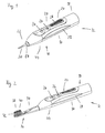
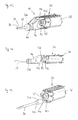
- Fig. 1 - 4th are basic body 10 according to the invention electric toothbrushes 12 shown, which, for example, in Fig. 2 and Fig. 4 shown brush heads 14 are attachable.
- the main body 10 has a substantially cylindrical outer contour and forms a handle 16 of the electric toothbrush 12.
- the base body 10 has a mounting section 18 in a lower end region, an actuating section 20 adjoining thereto and an attaching section 22 adjoining the actuating section 20 which is arranged on an end portion opposite to the setting-up portion 18.
- the set-up section 18 serves for a safe installation of the electric toothbrush 12 on a solid base, for example a loading or base station. He includes one in the Figures 1 - 4 invisible floor, which may be flat, for example, with a Aufstellausformung for inclusion in the loading or base station or with other functional formations.
- the actuating portion 20 extends approximately over two-thirds of the total length of the base body 10 and is in the use of the electric toothbrush 12 substantially of the palm of a user enclosed.
- On an upper side 24 it is equipped with externally accessible, soft elastic material shaped actuators 26 for controlling operating conditions of the electric toothbrush 12, for example, on and off, a continuous or discrete adjustment of operating conditions or operating speeds, etc. equipped.
- In the actuating portion 20 are on the surface otherwise formed by a hard material soft elastic adhesive elements 28, which prevent slipping of the user's hand when using the electric toothbrush 12, respectively.
- the actuating section 20 preferably tapers continuously in the direction of the attachment section 22.
- the Aufsteckabites 22 serves the mechanical coupling of the brush attachment 14 to the main body 10 of the electric toothbrush 12. It comprises in the in Fig. 1 shown embodiment of the base body 10 has an end portion of a driven shaft 30 and in the in Fig. 3 embodiment shown in addition a connecting piece 32 for rotatably receiving the brush attachment 14th
- the brush attachment 14 has a neck 34 whose free end region is predetermined for attachment to the slip-on portion 22 formed on the base body 10.
- the neck 34 is provided as a stick-like extension with a rounded cross-section smaller than that of the body 10.
- At the in Fig. 4 shown embodiment of the brush attachment 14 is at the top 24 of the neck 34 attached to an externally accessible actuator 36.
- the adjusting element 36 serves to select a pivoting range of a head 38 of the brush attachment 14 movable, in this embodiment, in particular reversibly rotatably arranged cleaning element 40th
- the head 38 forms an adjoining the neck 34, generally widening towards the neck 34 free end portion of the brush attachment 14. It serves to accommodate or storage of cleaning elements 40, which in the in Fig. 2 and Fig. 4 shown embodiments on the top 24 with bristles 42 and bundles of bristles 42 are occupied. On one in the Fig. 2 and 4 not visible, the upper side 24 opposite bottom 44, the head 34 may also be equipped, for example, with a tongue cleaner preferably made of soft material.
- the cleaning element 40 is fixedly disposed on the brush attachment 14 and performs in an active operating state of the electric toothbrush 12 together with the entire brush attachment 14 from the output shaft 30 transmitted reversing pivotal movement.
- the cleaning element 40 is pivotally mounted relative to the head 38 and the neck 34.
- the cleaning element In the active operating state of the electric toothbrush 12, the cleaning element carries out a reversingly rotating movement about an axis which runs almost at right angles to the longitudinal axis of the neck 34.
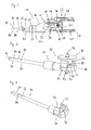
- a so-called inner frame 46 is arranged inside the main body 10 of the electric toothbrush 12.
- the inner frame 46 is in a side view of a portion of the interior of the electric toothbrush 12 in FIG Fig. 5 shown.
- the illustrated part extends from the outermost, brush-side end of the output shaft 30 to about the longitudinal center of the actuating portion 20.
- an inventive transmission 48, a drive unit 50 and a control unit 52 are arranged, the latter two in Fig. 5 only partially visible.
- the control unit 52 is partially disposed on the upper side of the inner frame 46 and includes a printed circuit board 54 having disposed thereon components and a switching element 56 for switching on and off of the active operating state of the electric toothbrush 12.
- the switching element 56 is corresponding to the actuating elements 26 which are accessible from the outside are arranged on the base body 10, formed.
- the actuating elements 26 are preferably formed of a soft elastic material and allow it to exert actuating forces on the switching element 56 when actuated.
- the drive unit 50 comprises an in Fig. 5 not shown energy storage in the form of one or more Batteries or a rechargeable battery or a power supply, which is electrically connected to an electric motor 58, respectively.
- the electric motor 58 provides on its associated drive axle 60 a continuous rotational movement in a rotational direction through 360 °.
- the rotational speed of the electric motor is - with connected gear 48 and plugged brush attachment 14 - between 1000 revolutions per minute (RPM) to 15000 U / min, preferably 3000 U / min to 8000 U / min 8000 rpm to 12000 rpm.
- RPM revolutions per minute
- the operating voltage for feeding the electric motor 58 is 1.3 V to 3 V, with a current flow in the above-defined unloaded operation between 300 mA to 1500 mA, preferably 400 mA to 1200 mA.
- the transmission 50 is followed by the transmission 48 according to the invention on the inner frame 46.
- the transmission 48 transmits and converts the substantially continuous rotary motion provided by the electric motor 58 on the drive axle 60 into a reversing movement of the output shaft 30.
- the movement provided by the inventive transmission 48 described in detail on the output shaft 30 can in this case involve a reversingly pivoting movement the longitudinal center line of the output shaft 30, a reversing translational reciprocating movement in the direction of the output shaft 30 or a combined Movement be reversing pivoting and reversing translational motion components.
- connection piece 32 is provided with substantially parallel to the output axis 30 extending edges to - as already mentioned - a non-rotatable Arrangement of the brush attachment 14 on the body 10 to ensure.
- the inner frame 46 For storage of the output shaft 30 on the inner frame 46, the inner frame 46 is provided on the output shaft side with a corresponding, not visible in the figures Achsausnaturalung.
- the diameter of the Achsausnaturalung is chosen so that the output shaft 30 can move freely translational and / or rotating therein, the penetration of liquids and solids but is largely excluded.
- the transmission 48 includes in addition to the in Fig. 5 visible drive gear 68, which rotatably on the drive axle 60 of the electric motor 58 is arranged, in particular in Fig. 6 highly visible crown wheel 70 with a arranged on the toothed side surface cam 72 and a particular in Fig. 7 shown, interacting with the cam 72 customers 74.
- the output shaft 30 is arranged rotationally fixed.
- the output shaft 30 is in turn rotatable and optionally also displaceable in a driven axle sleeve 75, which in Fig. 6 is visible, stored.
- the position of the pickup 74 relative to the inner frame 46 is set to the desired pivoting and optionally Verschiebungslivsgrad.
- the output shaft sleeve 75 thus serves to support the output shaft 30.
- the spur gear drive gear 68 is engaged with not shown teeth of the crown gear 70 for simplicity reasons and forms due to the smaller number of teeth of the drive gear 68 relative to the crown gear 70 a reduction 76.
- the reduction 76 is a first gear stage of the transmission 48 in the form of a crown gear .
- the reduction ratio is 0.2 to 0.9, preferably 0.4 to 0.6, ie, the speed of the crown gear 70 is reduced by said reduction ratio relative to the engine speed and the torque increases accordingly.
- the drive shaft 60 of the drive gear 68 is at least approximately at right angles to the mounted in the inner frame 46 Kronenradachse 78 (see Fig. 6 ).
- the drive shaft 60 is parallel, but not coaxial with the output shaft 30 is positioned.
- the drive axle 60 and the output shaft 30 must also enclose the same angle. For reasons of ergonomics, an angle of less than 20 °, preferably between 3 ° and 10 °, is preferred.
- the drive shaft 60 of the drive gear 68 is, as in the in Figure 6 embodiment shown, also oriented approximately at right angles to the mounted in the inner frame 46 Kronenradachse 78.
- the cam 72 can be manufactured as a separate component from the crown gear 70. This allows the drive shaft 60 and the output shaft 30 are positioned with a corresponding storage in the same flight.
- the pickup 74 is for this purpose, for example, to be rotated by 180 ° about its longitudinal axis and provided with a corresponding recess through which the cam 72 arranged on the crown wheel 70 in a rotationally fixed manner engages with sufficient clearance.
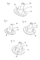
- the cam 72 may be in shape and arrangement with respect to the crown wheel axis 70, as in 8 to 11 shown by way of example, be executed in various ways.
- the cam 72 has in each case at least one cam wall 80, which extends substantially parallel to the crown wheel axis 78 and at right angles to the toothed side face of the crown wheel 70.
- the pickup 74 clampingly engages the cam 72 and slidingly scans the cam wall 80 of the cam 72 by means of two rounded scan edges 82 at a fixed distance. Due to the fixed spacing of the scanning edges 82 and the cross-section of the cam 72 deviating from a circular shape or, if appropriate, its eccentric arrangement with respect to the crown wheel axis 78, the pickup 74, together with the rotationally connected output shaft 30, is reversibly pivoted about its longitudinal center line within an angular range of less than 360 ° , Due to the pivotal movement of the pickup 74 and the thus different spacing of the scanning edges 82 from the crown wheel 70, it may be advantageous to slightly camber or shape the cam 72 in the direction of the crown wheel axis 78.
- the ratio of the distance between the longitudinal center axis of the output shaft 30 and the longitudinal center axis of the drive shaft 60 in the region of the pickup 74 to the distance between the longitudinal center axis of the crown gear axis driving the cam 72 and the longitudinal center axis of the cam 72 disposed on the crown gear 70 (ie the eccentricity of the cam 72nd ) is at least 10: 1.
- the cleaning element 40 is either fixed to the brush attachment 14 and the brush attachment 14 is attached directly to the output shaft 30 rotatably - as in the in Fig. 2 shown embodiment of the electric toothbrush 12 - or indirectly via a Aufsteckachse with a deflecting element is connected to the output shaft 30 - as in the in Fig. 4 shown embodiment of the electric toothbrush 12 - the reversing pivotal movement of the output shaft 30 is transmitted to the cleaning element 40.
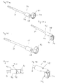
- the output shaft 30 itself has a nearly constant diameter over its entire length, which is between 2 mm and 6 mm, preferably between 2.5 mm and 4 mm.
- the output shaft 30 is provided on both sides with flats 84 in its end.
- the flats 84 have the task, in cooperation with corresponding mating surfaces of the brush attachment 14 and the Aufsteckachse to transmit torque.
- the remaining cross section the output axis 30 is in the region of the flats 84 0.5 mm to 3.5 mm, preferably 1.5 mm to 2.5 mm.
- the length of the flats 84 along the output axis 30 is between 8 mm and 14 mm, preferably between 10 mm and 12 mm.
- shoulders 86 are formed in the transition from the flattened cross section of the output shaft 30 to its full circular cross section.
- the shoulders form an angle with the longitudinal center line of the output shaft 30 from 30 ° to 60 °, preferably from 40 ° to 50 °.
- the beginning of the shoulders 86 is positioned about 15 mm to 22 mm, preferably 17.5 mm to 19.5 mm, measured from a face side 87 of the main body 10 (without connecting piece 32).
- the notches 88 are disposed at a distance of about 12 mm to 20 mm, preferably 15 mm to 17 mm from the end face 87. They preferably have a depth of 0.2 mm to 0.8 mm, preferably from 0.35 mm to 0.65 mm. A bottom of the notches 88 has a width of about 0.3 mm to 1.5 mm, preferably 0.7 mm to 1.1 mm.
- the output shaft 30 is rounded brush head side in its end to reduce the risk of injury and to facilitate the assembly process when attaching the brush attachment 14.
- the output shaft 30 is preferably made of a metal, such as stainless steel, and has a free length from the end face 87 measured from 25 mm to 35 mm, preferably from 28 mm to 32 mm.
- crown wheels 70 with arranged thereon cam 72 based on FIGS. 8-11 described.
- the teeth of the crown wheels 70 are not drawn for reasons of simplification and only symbolically represented by a ring.
- each cylindrical Kronach sleeves 90 are formed on the cam 72 opposite the toothed side surface of the crown gear 70 . They serve to support the crown wheel 70 along the crown gear axis 78 relative to the inner frame 46.
- a cam 72 In Fig. 8 an embodiment of a cam 72 is shown.
- This cam 72 has a circular to slightly elliptical (with a ratio of Main vertex to side vertex of 1.01: 1 to 1.1: 1 preferably 1.03: 1 to 1.07: 1) cross-section and is eccentric with respect to the Kronenradhülse 90 and not shown Kronenradachse 78 arranged.
- the distance from the crown gear axis 78, which has the function of a rotation axis for the crown gear 70, to a center axis of the cam 72 is 0.5 mm to 3.0 mm, preferably 1.5 mm to 2.5 mm.
- FIGS. 9 and 10 Cams with a substantially triangular cross-section and in Fig. 11 a cam having a substantially pentagonal cross-section shown.
- the cam walls 80 of the cams 72 are always rounded and also include the corners of the respective n-corner shape to allow a sliding scan through the sensing edges 82 of the pickup 74.
- the radius of curvature for the corners is 1.32 mm for the triangular section and 0.5 mm for the pentagonal section.
- the radius of the rounding of the sides is 7.27 mm in the triangular section and 14.44 mm in the pentagonal section.
- the rounding radius for the corners decreases as n increases, ie approaches 0 mm, and the radius for rounding the sides increases as n increases.
- the cross-sectional shapes of the cam 72 must be designed according to each other due to the fixed distance of the scanning edges 82 and in particular have a radius.
- the cross sections of the cams are designed as a rounded regular n-corner.
- the cam walls 80 of the cams 72 are each formed such that each bounded by the curve walls 80, in a cross-sectional plane of the cam 72 through the center of its cross-sectional shape extending cross-sectional length has approximately the same length.
- the substantially n-corner cams 72 may be both eccentric with respect to the crown gear axis 78 and, as in FIG 10 and 11 shown concentrically with respect to the Kronenradachse 78 may be arranged.
- For n-angular cross-sectional shapes of the cam 72 results in a complete rotation of the crown wheel 70 by 360 ° n-reversing pivoting of the pickup 78 and the associated output shaft 30th
- a "large” reversing pivoting of the pickup is superimposed by additional n “smaller” pivots. Due to the eccentric arrangement of the cam 72, for example, a dominant basic tilt can be superposed with a "large” pivot range of a plurality of "smaller” pivoting movements.
- the output shaft 30 pivots exactly one time per revolution of the crown wheel 70 due to the eccentric arrangement of the cam 72 and n times due to the n-angular configuration of the cam 72. This arrangement will be described below in connection with Fig. 19 described in detail.
- n> 1 ie for cams 72 with 3, 5, 7... - shaped cross-sectional shapes, the combination of the cam 72 with the pickup 74 forms an output-side second gear stage in the form of a gear-less transmission 92 (see, for example Fig. 6 ).
- the corresponding transmission ratios 3, 5, 7 ... cause an increase in the pivoting frequency of the pickup 74 relative to the rotational speed of the crown wheel 70 by just these said ratios.
- the deflection of the pickup 74 causes a total (or total) depending on the specific cross-sectional shape of the cam 72, a maximum deflection of the pickup 74 and the associated output shaft 30 between 1 ° and 23 °, preferably between 3 ° and 15 °, especially preferably about 5 ° to 12 ° between its maximum deflection positions (ie the full deflection angle in a movement from the very left outside to the far right outside).
- a maximum deflection of the pickup 74 and the associated output shaft 30 between 1 ° and 23 °, preferably between 3 ° and 15 °, especially preferably about 5 ° to 12 ° between its maximum deflection positions (ie the full deflection angle in a movement from the very left outside to the far right outside).
- the second gear stage is preferably housed in the main body 10 of the electric toothbrush 12.
- at least one of the two gear stages is arranged in the brush attachment 14.
- this particular embodiment by means of cam 72 and pickup 74 is only an example and other means not shown here can be used to implement the at least second, translating gear stage.
- this second gear is not by means of toothing, but by means Realized curves or cams and correspondingly shaped customers.
- FIG. 12 is similar to the representation in Fig. 6 a structural unit consisting of the crown wheel, the cam 72, the pickup 74 and the associated output shaft 30 shown.
- a cam extension 94 In contrast to the embodiments described so far, however, in this case, in the 8 to 11 Kronachshülse shown 90 replaced by a cam extension 94.
- This cam extension 94 passes through a Abtastausbloodung 96 in the pickup 74.
- the Abtastausbloodung 96 has a limited by a scan wall 98 rounded cross-section, within which the cam extension 94 can perform as low-friction rotation about the Kronenradachse 78 and at the same time a pivoting movement of the pickup 74 about the output axis 30 is enabled.
- the cam extension 94 has in the in FIGS. 12 and 13 a circular to slightly elliptical (with a ratio of main vertex to side vertex of 1.01: 1 to 1.08: 1, preferably 1.02: 1 to 1.05: 1) shown cross-section and is arranged eccentrically with respect to the Kronenradachse 78.
- the distance from the crown gear axis 78, which has the function of a rotation axis, to a center axis of the cam extension 94 is 0.1 mm to 1.5 mm, preferably 0.2 mm to 0.8 mm.
- Fig. 13 is the in Fig. 12 shown arrangement shown again in a side view, now in particular the penetration of the cam extension 94 is clearly visible through the Abtastausbloodung 96.
- cam extension 94 can be provided with a rounded, essentially n-corner-shaped cross section, wherein n is an odd positive number and for n> 1, the formation of a gear-free further translation 100 is effected.
- the cam extension 94 can be arranged both eccentrically, as well as concentrically or coaxially with respect to the crown gear axis 78.
- cam extension 94 is formed such that each of its outer wall is bounded on two sides, in a cross-sectional plane of the cam extension 94 through the center of its cross-sectional shape extending cross-sectional length is at least almost the same length.
- FIG Fig. 15 An example of a cam extension 94 having a triangularly rounded cross-section that is eccentric with respect to the crown wheel axis 78 is shown in FIG Fig. 15 shown.
- the cam extension 94 is combined with a pentagon-shaped rounded cam 72 on the crown wheel 70.
- the cam 72 is here arranged concentrically or coaxially with respect to the crown wheel axis 78.
- a movement pattern that can be generated thereby on the output shaft 30 will be described below in connection with FIG Fig. 20 explained.
- FIGS. 14 and 15 shown embodiments of cam 72 cylindrically shaped and concentric with respect to the crown wheel 70 to order.
- the output shaft 30 is merely reversibly translationally reciprocated and not additionally reversibly pivoted.
- the cylindrically shaped, concentrically arranged cam 72 stabilizes the pickup 74 laterally and prevents the pivoting movement.
- the cam extension 94 is formed cylindrically and concentrically and stabilizes the pickup 74 in the direction of the output shaft 30 and prevents the translational movement.
- the caused by the rotation of the cam extension 94 reversing translational reciprocating motion causes the output shaft 30, a shift in its longitudinal direction between 0.5 mm and 2 mm, preferably between 0.5 mm and 1.5 mm.
- a reversing translational movement component of the cleaning element 40 can be used, for example, in the in Fig. 2 shown embodiment of an inventive electric toothbrush 12 be realized. It should be noted, however, that in this case appropriate safety measures must be taken so that no parts of the body or skin areas of the user can be trapped by the brush body 14, which lifts off from the base body 10.
- Such a safety measure is, for example, the insertion of a bellows-type hose between the end portion of the Aufsteckabêts 22 of the body 10 and the free end portion of the neck 34 of the brush attachment 14 or similar means of soft elastic material, which minimize the resulting gap by the translational movement of the brush attachment 14.
- Another safety measure is to let the brush attachment 14 end within the body 10 and thus to ban the risk of entrapment.
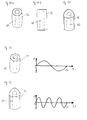
- FIGS. 16 to 20 the movement patterns are explained, which can be achieved with the respective units shown on the left side, consisting of the crown wheel 70, the cam 72, the Kronach sleeve 90 and the cam extension 94.
- the ordinate in each case represents a deflection angle ⁇ during the pivoting of the output shaft 30.
- the ordinate also represents a deflection length s.
- Fig. 18 In the graphic representation of Fig. 18 is the deflection angle ⁇ of the output shaft 30 in dependence on the rotation angle ⁇ of the crown wheel 70 and the time for a substantially pentagonal cam 72 which is arranged concentrically with respect to the Kronenradachse 78 shown.
- the deflection angle ⁇ passes through five sinusoidal periods in one revolution of the crown wheel 70. Consequently, there is a transmission ratio of 5.
- Fig. 19 is a movement pattern related to Fig. 17 already mentioned case of a substantially triangular cam 72 which is mounted eccentrically with respect to the Kronenradachse 78 shown.
- the cam 72 is displaced along an angle bisecting, from the center of the circumference of the cam cross section in the direction of a corner. Consequently, the functional dependence of the deflection angle ⁇ on the rotational angle ⁇ of the crown wheel 70 (or the drive axis 60) results essentially from a superimposition of the in FIGS. 16 and 17 illustrated functional dependencies.
- Such a function curve leads to a jitter-like deflection of the output shaft 30.
- Fig. 20 the movement pattern of the output shaft 30 is shown under an additional influence of the cam extension 94.
- the deflection angle ⁇ of the output shaft 30 is plotted on the ordinate.
- the abscissa in this case represents a deflection length s of the output axis 30.
- the movement pattern for a complete revolution of the crown wheel 70 is represented by a rotation angle of 2 ⁇ (360 °).
- Cam 72 cross-sectional shape, position with respect to the crown wheel axis 78
- Cam extension 94 cross-sectional shape, position with respect to the crown wheel axis 78 swiveling (easy) oval, eccentric oval, concentric n times swiveling n-angular, concentric oval, concentric translatory reciprocating (easy) oval, concentric oval, eccentric n times translationally reciprocating oval, concentric n-angular, concentric swiveling (simple) with overlapping n times swiveling n-angular, eccentric oval, concentric translatory reciprocating (simple) with superimposition n times translationally reciprocating oval, concentric n-angular, eccentric n times swiveling with translatory reciprocating (easy) n-angular, concentric oval, eccentric n times swiveling with n-angular, eccentric n times swiveling with n
- the remark "simple" means that exactly one complete swing period for the deflection angle ⁇ is traversed per complete revolution of the crown gear 70.
- the variable n is to be replaced by an odd positive number, for example 3, 5, 7, 9 and so on. From the above table it can be seen that a large number of pivoting movements as well as reciprocating movements can lead to complex movement patterns of the output shaft 30 and the cleaning elements 40 connected thereto. These can be adapted to provide optimal cleaning of the teeth and dental interstices, as well as improved circulation of the gums by means of appropriate massage movements. Intensive tests with cleaning robots have shown that high-frequency movements with smaller deflections achieve the best cleaning values, especially in the interdental area. In particular, above-described overlapping movement patterns have proven to be useful. In particular, it has been possible to perfect the movement patterns of the so-called bass method, which is used for manual toothbrushes, with the method described above.
- the pivotal movement of the movable cleaning element 40 is at a frequency between 3000 U / min and 15000 U / min, preferably from 8000 U / min to 12000 U / min, more preferably between 8'000 and 10'000 U / min. realized.
- the translational reciprocation of the cleaning element 40 is at a frequency between 1000 rpm and 12000 rpm, preferably between 2000 rpm and 4000 rpm, or between 8000 rpm and 12000 rpm.
- gears 48 it should be noted that the play between the teeth of the drive gear 68 and the crown gear 70 and between the cam 72 and the scanning edge 82 and the cam extension 94 and the Abtastrisen 98 is kept as low as possible to beat in the system and To keep a noise nuisance outside the body 10 as low as possible.
- the intermeshing elements may be provided with a lubricant, such as silicone grease, to reduce potential frictional effects. It is likewise possible to equip the components of the transmission 48, which are generally made of a hard material, completely or at certain contact or bearing points with a damping plastic in order to achieve the most uniform and low-noise conversion of the movements.
- the output shaft 30 and the drive shaft 60 may be designed in several parts, wherein the individual part are connected to each other via coupling elements of a damping plastic. Due to this allowed torsional movements of the axes is a softer Start of the movements possible and a risk of injury from abrupt movements is reduced.
- a "soft bearing" can be designed without interrupting the output shaft 30, for example, by the connection between the pickup 74 and output shaft 30 is made soft, that is, that a soft layer between the two elements 74, 30 is applied. To reduce noise and appropriate bearings can be designed which dampen the vibration transmission via the output shaft 30.
- the scanning edges 82 or the scanning walls 98 can be coated with a soft-elastic layer or to produce the entire pick-up 74 from a somewhat softer material.
- existing hollow or resonance chambers can be filled with sound-absorbing material for noise reduction in the interior of the body.
- the brush body 102 is preferably by means of produced by injection molding. It gives the brush attachment 14 a basic stability and serves as its backbone.
- an opening 104 of an axle receptacle 106 is visible, in which the flattened end region of the output shaft 30 can be inserted.
- the axle receptacle 106 is equipped with two not visible in the illustrations dividendabflachonne, which are formed according to the flats 84 of the output shaft 30, and the interaction of which ensures the transmission of torque from the output shaft 30 to the brush attachment 14.
- the opening 104 is preceded by a cylindrical holding recess 107 on the end region side.
- the holding recess 107 serves to allow the brush attachment 14 to be placed on a corresponding holder for storage in a base station.
- the retaining recess 107 occupies a substantial part of the neck cross-section and has a longitudinal depth of less than 10 mm, preferably less than 5 mm.
- the axle receptacle 106 and the retaining recess 107 are preferably arranged coaxially with one another.
- the holding recess 107 can still cover a second function: by a corresponding embodiment, a pivotable brush attachment 14 can be formed, which also on the in FIG. 3 and FIG. 4 shown basic body 10 can be plugged.
- an outer shell of the brush head 14 surrounding the retaining recess 107 surrounds the connecting piece 32 in an apron-like manner.
- the base body 10, which can be used both with brush heads 14 for oscillating movements and also for pivoting movements, are preferably only one Gear 48 equipped to provide the pivoting movement. An additional superimposed translational motion component appears less useful here.
- On Aufsteckbürsten groundSuper 102 also supporting stumps 108 are formed from hard material both at the head end portion as well as in the neck-side portion.
- These Abstützstümpfe 108 serve various functions: the support in an injection molding in a subsequent injection molding process step for molding a soft elastic material, the support of the Aufsteckbürsten groundSystems 102 when labeling and optionally provide with their visible on the surface of the brush attachment surface 14 suitable areas on which labels, for example can be applied by hot stamping, inkjet or tampon Beschriftungsvon.
- the brush head body 102 is already equipped with bristle receiving holes 110 on the head side. In addition, both are located on the in Fig. 21 shown top as well as the in Fig. 22
- the vent hole 112 formed on the top 24 and the axle receiving side at the bottom 44 is used in the injection molding of the support of a core for forming the axle 106.
- the top vent hole 112 in the brush body 102 is covered in the subsequent injection molding process step of soft elastic material ,
- the remaining under-side vent hole 112 is not covered with soft elastic material and serves to escape air during insertion of the Output shaft 30 and the flushing of the axle 106 with liquid for cleaning purposes.
- Fig. 22 is in the neck-side end portion of the brush body 102, between the two lower-side Abstützstümpfen 108, a substantially U-shaped recess 113 visible.
- the U-shaped recess 113 surrounds a tongue-like spring element 114 with snap-on cam formed thereon, which cooperates with a notch 88 on the output shaft 30 in order to hold the brush attachment 14 on the main body 10 of the electric toothbrush 12.
- FIGS. 23 and 24 is the top 24 and the bottom 44 of the in Fig. 21 respectively.
- Fig. 22 shown brush body 102 after over-molding with a soft elastic material shown.
- the slip-on brush body 102 which is overmoulded with soft-elastic material, is then equipped with bristles 42 in the head region, for example by means of a classic bristle-type process.
- the brush attachment 14 is preferably made of a plurality of plastic materials. Preferably, in each case a hard and a soft material is used. The different plastics adhere to each other. With a combined use of hard and soft materials in the brush attachment 14, a certain flexibility of the brush attachment 14 can be achieved. A combination of different layer thicknesses and shapes makes it easy to adjust the flexibility.
- a structure can be formed, which is a removal of the brush attachment 14 from the main body 10th in which it provides a restrained structure for the fingers of the human hand.
- a support surface 108 is mounted on the underside 44 of the brush head 38 which fixes and supports the brush head 38 during the bristling process.
- the completed brush attachment 14 is in a sectional view in Fig. 25 shown.
- the hard material used for the production of the brush body 102 is shown with a different hatching than the soft-elastic material sprayed in a second process step.
- the axle receptacle 106 and the uncovered vent hole 112 are also clearly visible in this illustration.
- the spring element 114 clearly recognizable, which is formed on the brush attachment 14 on one side and therefore allows the brush attachment 14 to be plugged in two different orientations about its longitudinal axis on the base body 10.
- the spring element 114 is partially surrounded by soft elastic material.
- the spring element 114 must already yield resiliently in the first injection molding process step, during the removal of the core, which serves to form the axle receptacle 106, due to its elastic properties.
- the same embodiment of the spring element 114 can also be used in an oscillating brush, as in FIG Fig. 26 shown, are applied.
- the in Fig. 25 shown brush head on the head 38 in addition to be equipped with a rubber-elastic cleaning structure, not shown, in the form of a tongue cleaner.
- scraper edges are preferably formed from the soft elastic material, which can remove plaque and contaminants from the tongue during a movement.
- Similar soft elastic material can be used to form in the bristle field soft elastic massage elements, preferably rubber-elastic cleaning blades or cleaning structures.
- the scraper edges of soft elastic material are preferably transversely to the direction of movement of the brush head. If, for example, the brush head performs a reversing pivoting movement, then the scraper edges are essentially aligned in the longitudinal direction of the brush attachment 14.
- the scraper edges are substantially aligned in the transverse direction to the longitudinal axis, ie substantially at right angles to the longitudinal axis of the brush attachment 14.
- the cleaning structures may also be formed of hard material, which of course they are not rubber-elastic.
- Fig. 26 is a sectional view of the already in Fig. 4
- This embodiment of the brush attachment 14 allows a reversing rotating or reversing oscillating movement of the cleaning element 40.
- the attachable to the output shaft 30 Aufsteckachse 116 with the deflecting element 118 is clearly visible.
- the adjusting element 36 whose position determines the relative positioning of the Aufsteckachse 116 within the neck 34 and consequently determines the pivoting angle range of the cleaning element 40, recognizable.
- the cleaning element 40 in this embodiment has a disk-shaped bristle carrier 120 and has been equipped with bristles 42 during manufacture in a conventional ironing process by means of a metal anchor, an AFT (Anker Free Tufting) or an IMT (In Mold Tufting) process.
- AFT Arker Free Tufting
- IMT In Mold Tufting
- the bristle carrier 120 is fastened on a turntable 122, which is mounted pivotably on the brush head body 102 via a turntable axis 124 which is fastened centrally in the turntable 122.
- the turntable axis 124 extends essentially at right angles to the longitudinal extent of the plug-on axis 116 or the output axis 30.
- the turntable 122 has a slot 126 into which the deflection element 118 engages.
- the radial engagement position of the deflecting element in the turntable 122 is influenced, so that between a larger and smaller pivot angle of the turntable 122 and thus the Cleaning element 40 can be selected.
- the pivot angle is less than 35 °, preferably less than 30 °. Further information on the internal structure of this embodiment of a brush attachment 14, for example, the CH 688537 be removed.
- FIGS. 27 and 28 Another embodiment of a brush attachment 14 with a pivotable cleaning element 40 is shown in FIGS. 27 and 28 shown. Unlike the in Fig. 2 and Fig. 21 to 25 In the embodiment shown in which the entire brush attachment 14 is pivoted together with the cleaning element 40 is similar to that in FIG Fig. 26 shown embodiment of AdvicewinbürstengrundSuper 102 firmly attached to the base body 10 and not pivot.
- the cleaning element 40 is fixedly connected to an axle extension 128.
- the axle extension 128 in turn is pivotally mounted in the brush body 102.
- the cleaning element 40 can also be arranged at an angle or inclined to the attachment axis 116.
- the angle of inclination is preferably less than 30 °, particularly preferably less than 15 °.
- FIGS. 29 and 30 is an evolution of the in FIGS. 27 and 28 shown embodiment of a brush attachment 14.
- alternately stationary cleaning elements 40s and pivotally movable cleaning elements 40 are arranged along the longitudinal extent of the brush attachment 14.
- the movable cleaning elements 40 are, as in Fig. 30 visible, non-rotatably connected to the axle extension 128.
- the head 38 has to be made strongly thickened in order nevertheless to achieve the required stability.
- the reversing pivoting movement can be additionally superposed with a translational reciprocating movement.
- FIGS. 31 and 32 Another embodiment of a brush attachment 14 is in the FIGS. 31 and 32 shown. Also in this embodiment, a pivotable cleaning element 40, which end-side of the brush attachment 14th is arranged to be pivoted against a neck side positioned stationary cleaning element 40s. The pivotally movable cleaning element 40 is in turn rotatably connected to the axle extension 128 and is deflected in the active operating state of the electric toothbrush 12 due to a mechanical coupling with the output shaft 30 relative to the neck 34 and the stationary cleaning element 40s.
- this embodiment of a brush attachment 14 is also suitable for use in a combined movement with a reversing pivoting and a reversing translational motion component.
- the reversing translational motion component causes in this case a reciprocating motion of the pivotally movable cleaning element 40 along the longitudinal extent of the output shaft 30.
- the transmission 48 for example, the in FIGS. 12 to 15 and in Fig. 20 shown cam extension 94.
- the axle extension 128 can be made flexible in the area between the stationary and movable cleaning element 40s and 40 by a specific choice of material and / or a targeted material weakening. In this way, the movable cleaning element 40 can be deflected flexibly with respect to the stationary cleaning element 40s if the cleaning pressure is too high.
- the in the FIGS. 27 to 32 illustrated embodiments of the brush attachment 14 are each configured so that the neck 34 is attachable or releasably connected to the connecting piece 32 and therefore does not move with the movable cleaning elements 40.
- the zones where the Aufsteckachse 116 from the Aufsteckbürstengrund stresses 102nd emerges at least partially surrounded by soft elastic material. This in turn serves as anti-trap protection and / or for sealing and storage.
- zones of specially designed soft material can be used in all design variants. These form a resilient buffer, which prevent pinching of lips, mouth surfaces, etc.
- a concertina-type bellows could be formed of soft material.
- the movement compensating structures of soft material conceivable.
- Fig. 31 and Fig. 32 it is also possible to arrange stationary cleaning elements 40s in the free end region of the brush attachment 14 and to position the movable cleaning element 40 on the neck side.
- stationary cleaning elements 40s in the free end region of the brush attachment 14 and to position the movable cleaning element 40 on the neck side.
- the brush attachment 14 is considered to have a length of 55 mm to 85 mm, preferably 65 mm to 75 mm, measured from its free end to the shank end of the Brush head 14.
- the vent hole 112 opened in the completed brush head 14 is located in the longitudinal direction at a distance of 25 mm to 35 mm, preferably from 28 mm to 32 mm, from the shank-side end of the brush head 14.
- the snap cam of the spring element 114 in the in FIGS. 21 to 25 shown embodiment is located in the longitudinal direction between 12 mm to 20 mm, preferably 15 mm to 17 mm from the Aufsteck stoolen end of the brush attachment 14.
- polypropylene polypropylene
- PET polyester
- PCT polycyclohexane dimethanol terephthalate
- PCT / PCT-A acid-modified
- PCT-G polycyclohexane dimethanol terephthalate
- PE polyethylene
- PS polystyrene
- SAN polymethyl methacrylate
- PMMA acrylic butadiene styrene
- ABS polyoxymethylene
- PA polyamide
- polypropylene (PP) having a modulus of elasticity of 1000 N / m 2 to 2400 N / m 2 , preferably from 1300 N / m 2 to 1800 N / m 2 is used.
- soft elastic material for example, low density polyethylene (PE-LD), high density polyethylene (PE-HD), polyethylene (PE), polyvinyl chloride (PVC), elastomeric material such as polyurethane (PUR) or a thermoplastic elastomer (TPE), preferably a thermoplastic elastomer (TPE) used. Also possible is the use of polyolefin-based elastomer.
- the Shore A hardness of the soft elastic material used is preferably less than 90.
- the thickness of layers of soft elastic material is more than 0.2 mm, preferably more than 0.5 mm.
- Soft elastic material with a Shore A hardness of less than 50, preferably less than 35, is used both on the main body 10, as well as on the brush attachment 14, for damping vibrations, vibrations and noise emissions that occur in the active operating state. These material properties provide a good compromise to optimally ensure the functions that are to be met with the soft elastic material.
- thin layers of soft elastic material can also be formed in the erection section 18 or above labeling fields.
- soft elastic material is also used for training for the head 38 and on the cleaning element 40 arranged cleaning elements, such as an already mentioned tongue cleaner or soft elastic cleaning blades.
- the soft-elastic cleaning blades can outside the bosten 42 standing around or arranged within bristle fields.
- the bristles 42 themselves are preferably made of polyamide or polyester with a diameter of 0.1 to 0.2 mm, preferably from 0.125 mm to 0.175 mm. They are arranged in bristle bundles.
- the relatively small-shaped head 38 has 20 to 30, preferably 22 to 28 bundles of bristles 42.
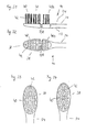
- Various forms of bristle arrangements are in the following FIGS. 33 to 41 shown.
- FIGS. 33 and 34 shown embodiments of arranged on heads 38 cleaning elements 40 are particularly suitable for electric toothbrushes 12 which produce a reversibly pivoting or reversing translational movement of the cleaning elements 40 in the active operating state.
- Analogous to the considerations with the tongue cleaner is preferably a part of the cleaning elements 40 aligned transversely to the direction of movement.
- this relates to elongated bristle bundles whose longitudinal extent in a plan view of the upper side 24 is greater than their transverse extent) or elongated, lamellar cleaning elements 40 made of soft material.
- bristles 42 are combined into bundles of bristles above oblong rounded, sickle, C or crescent-shaped or oval bases.
- a wiping effect is achieved with a reversing pivoting movement.
- bristle bundles with their longitudinal axis are also arranged at right angles to the longitudinal axis of the neck 34 in order to achieve such a wiping effect even with a reversing translational reciprocating movement of the head 38.
- a movable cleaning element 40 is therefore particularly suitable for a combined movement of the cleaning element 40 with a reversibly pivoting and a reversing translational motion component.
- the illustrated embodiments of cleaning elements 40 can of course also be used in manual toothbrushes. With manual use become similar Cleaning movements, of course, with much lower frequency used.
- movable cleaning elements 40 are arranged above a substantially circular or longitudinally slightly elliptically shaped bristle carrier 120 and in particular for use in reversing oscillating motion forms provided (see. Fig. 4 and Fig. 26 ).
- these cleaning elements 40 are also provided with bristles 42 above substantially elongate bases (see FIG Fig. 35, Fig. 36 ) or crescent-shaped bases (see FIGS. 37 and 38 ) arranged.
- the longitudinal axes of the elongated base surfaces of the bristle bundles are preferably arranged at least approximately at right angles to the pivot axis about which the cleaning element 40 oscillates in a reversing manner.
- FIG. 39 to 41 Embodiments of cleaning elements 40 are shown in which stationary cleaning elements 40s are combined with pivotally movable cleaning elements 40.
- the reversibly oscillatable cleaning element 40 is adjacent to a stationary cleaning element 40s, which is arranged at the free end area of the head 38 and has a rounded triangular base area.
- FIG. 41 is only the neck side of the pivotally movable cleaning element 40, a stationary cleaning element 40s arranged.
- movable cleaning elements 40 according to the FIGS. 35 to 38 with the in the Figures 39-41 shown cleaning elements 40, 40s are combined.
- the bristles of the illustrated embodiments of cleaning elements 40 can be done in various ways, for example by means of conventional anchor plates or as already mentioned by means of IMT or AFT method.
- These bristle bundles with comparatively large expansions of the bases in different directions combine the wiping effects for different directions of movement of the cleaning elements 40.
- the two bristles also allow greater freedom of design with respect to the appearance of the bristle field.
- bristles 42 rising from the bristle carrier 120 substantially at right angles or bundles of bristles 42 it is also possible to form bristles 42 arranged X-shaped on a cleaning element 40, 40s.
- the X-shaped bristles 42 are then at an angle of 3 ° to 20 °, preferably 8 ° to 14 ° to each other.
- bristles 42 or bristle bundles with longer and / or sharpened bristles 42, in particular on the outer edges of the cleaning elements 40, 40s.
- cleaning elements 40 with bristles 42 on substantially round or slightly oval bases to bristle bundles, which then serve in particular the cleaning of a gum line.
- a total of 120 cylindrical, as well as one-sided or two-sided sharpened bristles 42 can be used on the bristle carriers, in each case pure or combined or in combination with additional massage and cleaning blades or cleaning structures made of soft material.
- pointed bristles 42 on electric toothbrushes is already in the WO 2004/093718 described in detail and referenced.
- the described heads or cleaning elements and production methods can be combined directly with the electric toothbrush 12 according to the invention.
- the described brush heads 14 are preferably designed to be interchangeable. But it is also possible to make an electric toothbrush 12 with the inventive transmission 48 and the brush attachment 14 so that these elements are integrally formed and the brush attachment 14 is not replaceable. This is especially the case with cheap battery devices.
- the cleaning elements 40, 40s shown by way of example can also be replaced by other cleaning or active elements.
- these are, for example, generally interdental attachments, such as spiral brushes, toothpicks, etc., polishing elements, soft-elastic elements (eg professional cups) or tongue cleaner attachments.
- the transmission 48 according to the invention can also be used in other areas of personal care (face massage, nail care, head massage, wet and dry shaving, etc.) with correspondingly designed effective sets.
- Fig. 42 shows a section of the interior of another embodiment of an inventive electric toothbrush 12.
- the detail corresponds approximately to the in Fig. 5 in connection with a previously described embodiment shown illustration. Similar parts are in Fig. 42 with the same reference numerals as in Fig. 5 Mistake.
- the transmission 48 equipped only with a single gear stage. This gear stage is formed by a cam 72 and another pickup 132.
- the cam 72 is rotationally fixed on the in Fig. 42 invisible drive axle 60 of the electric motor 58 attached.
- the transmission 48 has no drive gear 68 and no crown gear 70.
- the transmission 48 of this embodiment produces less noise during operation and is simpler and less expensive to manufacture.
- the energy consumption and the preferred movement patterns can be adopted essentially analogously from the previously described embodiments.
- Fig. 42 a laterally arranged by the electric motor 58 control unit 52 for controlling the operating conditions of the electric motor 58 and an inner frame 46 for fixing the position of the further Abillers 132 with the output shaft 30 relative to the cam 72.
- the pickup 132 In the axial direction, parallel to the longitudinal axis of the output shaft 30, the pickup 132 is thereby supported on the one hand by a head bearing 134 of the inner frame 46 and on the other hand to the electric motor 58 through a stabilizing axis in its position.
- the output axis 30 extends parallel to offset in the figures as a dashed line indicated drive axis 60.
- a parallel axial offset between the axes 30 and 60 is not desired, this can by a correspondingly intermediate spur gear with at least two gears whose first gear is seated, for example, on the drive shaft 60 and in a second gear on which the cam 72 is mounted, engages compensated.
- the drive shaft 60 is positioned parallel but not coaxial with the output shaft 30.
- the drive axle 60 and the output shaft 30 must also enclose the same angle. For reasons of ergonomics, an angle of less than 20 °, preferably less than 10 °, is preferred.
- the inner frame 46 is opposite to in Fig. 42 modified variant shown so that the output shaft 30, the output shaft sleeve 75 and the pickup 74, 132 are at said angle to the drive shaft 60.
- a representation of this variant is in FIGS. 53 to 56 shown.
- the further pickup 132 is positioned or fixed along its longitudinal direction by a stabilizing axle 136.
- a so-called pickup extension can be formed which extends the further pickup 132 in the direction of the electric motor 58 and is supported thereon. This form of guidance of the further pickup 132 is associated with FIGS. 53 to 56 further described.
- Fig. 44 In the presentation of Fig. 44 is particularly clearly shown as a closed circumferential Um.umgriff 142 of the other consumer 132 engages the cam 72 radially with slight play.
- the pickup handle 142 is radially inward, the outer wall of the cam 72 opposite, equipped with a sensing wall 144.
- the cam 72 If, in the active operating state of the electric motor 58, the cam 72 is set in rotation about the drive axis 60, the outer wall of the cam 72 slides along the scanning wall 144 of the pickup handle 142 and moves the other pickup 132 together with its output shaft 30 in a reversing pivoting manner about the latter ,
- the play between the sensing wall 144 and the cam 72 and optionally the use of elastic materials prevents on the one hand a "beating" of the output shaft 30, and damage to the electric motor 58 under heavy loads during cleaning operation. It is also possible, the buyer Umgriff 142 also unilaterally open, so fork-like form to to give it a higher elasticity and thereby avoid the mentioned "beating".
- the friction of the cam 72 on the sensing wall 144 can be reduced by using suitable lubricants. Also, to reduce the friction, it is possible to form the cam 72 slightly cambered and to reduce the size of the sliding surface by an edge-like design of the sensing wall 144.
- the crowning is related to Fig. 49 described in detail.
- FIGS. 45 to 48 show various perspective views of the other consumer 132.
- the Umauerumgriff 142 and further a Abseparatingaus Principleung 148 are formed on a customer body 146.
- Said elements 132, 146, 142 are preferably made of a hard plastic material in an injection molding process.
- the rotationally fixed to the pickup body 146 arranged output shaft 60 is preferably made of a metal, such as a stainless steel.
- the Abilleraus Principleung 148 is formed.
- This Abilleraus Principleung 148 engages firmly on the inner frame 46 in the direction of the further Ab disturbings 132 projecting pin in the form of the stabilizing axis 136 with a game.
- the stabilization axis 136 is in FIGS. 42 and 43 recognizable.
- the Abilleraus Principleung 148 is substantially cylindrical or oval designed and equipped with an inner diameter which allows a reversing pivotal movement of the other Abitess 132 about the longitudinal axis of the output shaft 30 and simultaneously prevents displacement of the further Abitess 132 in the longitudinal direction. Because of this Abaueraus Principleung 148 in cooperation with the stabilizing axis 136 of the aforementioned subscriber extension is superfluous and no longer needed.
- the pick-off recess 148 is designed as an oblong hole, so that additionally a cam-type positive guidance of the further pickup 132 is effected in the longitudinal direction. If, in an active operating state of the electric motor 58, the further pickup 132 reversely pivots about the longitudinal axis of the output shaft 30, a reversing translational oscillating component of the pickup 132 in the longitudinal direction of the output shaft 30 is generated at the same time.
- the maximum longitudinal displacement in the reversing translational reciprocating component of the output shaft 30 is determined by a pitch angle ⁇ formed between the longitudinal axis of the pickup recess 148 and a transverse axis extending at right angles to the longitudinal axis of the output shaft 30 and the maximum rotational angle ⁇ of the output shaft 30.
- the pitch angle ⁇ is preferably set smaller than 45 °, more preferably between 10 ° and 30 °.
- the resulting maximum longitudinal displacement in the reversible translational reciprocating motion is less than 2 mm, preferably less than 1 mm.
- a gear ratio between the reversing pivotal movement component and the reversing translational reciprocating component of 1: 1 is ezielt.
- the superposition of the reversingly pivoting and reversing translational motion component leads to a closed trajectory of the cleaning element 40 connected to the output shaft 30.
- different movement patterns can be generated.
- the shape of the recess 148 is not limited to the in Fig. 47 but may also be S- or C-shaped or designed as another, not straight curve shape. For example, wavy shapes are also conceivable, by means of which larger transmission ratios of pivoting to translational motion component can be achieved.
- cam 72 two embodiments of cam 72 are shown.
- the in Fig. 49 shown cam 72 is configured substantially cylindrical, with its longitudinal central axis parallel to the longitudinal center axis of the drive shaft 60 (indicated by dashed lines) extends.
- the cam 72 is thus arranged eccentrically with respect to the drive axle 60.
- the itself when using such formed cam 72 resulting relationship between the deflection angle ⁇ of the output shaft 30 and the rotational angle ⁇ of the drive shaft 60 (or the time t) at a complete revolution of 360 ° (2n) is in 51 shown.
- This functional relationship corresponds to that in Fig. 16 shown course and causes a 1: 1 translation of the rotational movement of the drive shaft 60 in the reversibly pivoting movement of the pickup 132 and the output shaft 30th
- the deflection angle ⁇ follows a sinusoidal course and assumes in terms of magnitude maximum values as a function of the eccentricity of the arrangement of the cam 72 with respect to the drive axis 60 and the diameter of the cam 72.
- the 1: 1 ratio is mainly used in connection with an electric motor 58 for the previously described high speeds.
- the cam 72 has a cambered shape, that is, its outer surface is slightly outwardly curved and does not run parallel to the outer surface of the drive shaft 60.
- the diameter of the cam 72 changes along the longitudinal extent of the cam 72 and causes this particular shape
- the cam 72 has a diameter of 4.5 mm to 5.5 mm, preferably 4.9 mm to 5.1 mm, while in the median plane has a maximum diameter of 5 mm to 6 mm, preferably 5.2 mm to 5.4 mm.
- the cambered surface has a radius of curvature between 95 mm and 115 mm, preferably between 100 mm and 110 mm.
- the ratio of the radii of curvature in the end region of the cam 72 to one of these radii is diameter at the end to Diameter in center plane 1.01: 1 to 1.3: 1, preferably 1.02: 1 to 1.1: 1.
- the crowning of the cam 72 causes less friction to occur between the cam 72 or its outer surface and the further pickup 132 in the active operating state. This is also a noise reduction connected.
- the crowning is not mandatory for the functionality of the transmission 48. She is exemplary in Fig. 49a and Fig. 49b shown.
- the in Fig. 50 shown cam 72 is not equipped with a crown.
- the distance between the longitudinal center axis of the cam 72 and the longitudinal center axis of its axis of rotation acting as driving axle 60 is 0.1 mm to 0.6 mm, preferably between 0.2 mm and 0.45 mm. This distance is a measure of the eccentricity or imbalance of the cam 72, which causes the deflection of the further pickup 132 during its rotation.
- the distance between the longitudinal center axes of the drive axle 60 and the output shaft 30 is between 3 mm and 9 mm, preferably between 5 mm and 7 mm, particularly preferably about 6 mm.
- the ratio of the distances of the longitudinal center axes on the one hand from the output axis 30 to the drive axis 60 in the area of the pickup 74, 132 and on the other hand from the drive axis 60 to the eccentrically arranged cam 72 is 5: 1 to 90: 1, preferably at least 10: 1, particularly preferably 11 : 1 to 35: 1.
- This small maximum deflection angle ⁇ total in turn causes a small deflection of the cleaning elements 40, which in conjunction with the high speed of the electric motor 58 ensures a particularly effective and gentle cleaning of the teeth and the gums.
- the transmission ratio for example, with the in FIGS. 50 and 52 shown cam 72 are increased to achieve a higher frequency of movement of the movable cleaning element 40.
- This embodiment of the cam 72 is arranged centrally with respect to the drive axle 60.
- the cam 72 has a rounded, substantially triangular cross-sectional shape. It corresponds in form and function to those already in Fig. 10 and Fig. 17 shown cam 72, however, is mounted directly on the drive shaft 60 in this embodiment. In again Fig.
- FIGS. 53 to 56 a further embodiment of a transmission 48 according to the invention is shown, in which the drive axle 60 is arranged inclined with respect to the output shaft 30.
- the further customer 132 is along its longitudinal direction by an already mentioned Abauerfortsatz 150 and the head bearing 134th supported.
- the customer extension 150 is tapered towards its free end region.
- Characterized a Ab thriftfortsatzspitze 152 is formed, which rises almost pointwise on a the electric motor 58 associated or provided on the inside of the body 10 support surface 154.
- the customer extension tip 152 is preferably formed in continuation of the longitudinal center axis of the output shaft 30, so that in the active operating state of the electric motor 58 only a point rotation about a contact point of the customer extension tip 152 results on the support surface 154.
- the angle formed between the brush attachment 14 and the base 14 is the same that is trapped between the drive shaft 60 and the output shaft 30. For ergonomic reasons, this angle is less than 20 °, preferably less than 10 °.
- the inner frame 46 is opposite to in Fig.42 modified variant shown so that the output shaft 30, the output shaft sleeve 75 and the other customer 132 are at said angle to the drive axis 60.
- cam 72 may have cross sections in the form of rounded n-corners, where n is an odd positive number. All other features of the previously described embodiments according to the invention electric toothbrushes 12 can also on the in the FIGS. 42 to 56 shown embodiment are transmitted.
Abstract
Description
Die vorliegende Erfindung bezieht sich auf ein Getriebe für eine Elektrozahnbürste gemäss dem Oberbegriff des Anspruchs 1 und 23 sowie eine Elektrozahnbürste gemäss Anspruch 8 und 24.The present invention relates to a transmission for an electric toothbrush according to the preamble of
Elektrisch betriebene Zahnbürsten, sogenannte Elektrozahnbürsten, die zum Antrieb von Bewegungen an ihnen angeordneter Reinigungselemente Elektromotoren aufweisen, sind zum heutigen Zeitpunkt allgemein bekannt. Typischerweise werden dabei die an Aufsteckbürsten angebrachten Reinigungselemente nach einer Umwandlung einer vom Elektromotor bereitgestellten Drehbewegung über ein untersetzendes Getriebe schwenkend bewegt. Je nach der Bewegungsform die das Reinigungselement um eine ihm zugeordnete Achse vollzieht, unterscheidet man reversierend schwenkende, reversierend translatorische und kombinierte Bewegungen, die sowohl reversierend schwenkende wie auch reversierend translatorische Bewegungskomponenten aufweisen.Electrically operated toothbrushes, so-called electric toothbrushes, which have electric motors for driving cleaning elements arranged on them, are generally known at the present time. In this case, the cleaning elements attached to brush heads are typically pivotally moved by means of a reduction of a rotational movement provided by the electric motor via a reducing gear. Depending on the form of movement which carries out the cleaning element to an associated axis, there is a reversing pivoting, reversing translational and combined movements that have both reversing pivoting as well as reversing translational motion components.
Eine Elektrozahnbürste mit einem reversierend schwenkbaren Reinigungselement ist beispielsweise in der
Eine weitere Elektrozahnbürste ist in der
Eine Elektrozahnbürste, bei der im aktiven Betriebszustand ein an einer Aufsteckbürste angeordnetes Reinigungselement eine reversierend translatorische Hin- und Her-Bewegung ausführt, ist beispielsweise in der
In der
Weitere Ausführungsformen von Elektrozahnbürsten mit integrierten Getrieben sind beispielsweise in der
Zusätzliche Details zur Ausgestaltung von Aufsteckbürsten und Reinigungselementen sind unter anderem in den Druckschriften
Aufgabe der vorliegenden Erfindung ist es nun, ein Getriebe und einen damit verbundenen Bewegungsablauf für die Abtriebsachse bzw. das damit verbundene Reinigungselement einer Elektrozahnbürste bzw. eine Elektrozahnbürste mit einem derartigen Getriebe bereitzustellen, durch welches es möglich ist, eine für das Zahnfleisch schonende, besonders effektive Putzbewegung der Reinigungselemente auf eine kostengünstige Art und Weise bereit zu stellen.Object of the present invention is therefore to provide a transmission and associated movement for the output shaft or the associated cleaning element of an electric toothbrush or an electric toothbrush with such a transmission, by which it is possible, a gentle for the gums, particularly effective Provide cleaning movement of the cleaning elements in a cost-effective manner.
Diese Aufgabe wird durch ein Getriebe für eine Elektrozahnbürste gemäss dem Anspruch 1 und eine Elektrozahnbürste gemäss dem Anspruch 8 gelöst. Besonders bevorzugte Ausführungsformen sind mit den in den abhängigen Ansprüchen aufgeführten Merkmalen ausgestattet.This object is achieved by a transmission for an electric toothbrush according to
Das erfindungsgemässe Getriebe für eine Elektrozahnbürste dient der Übertragung und Umformung einer Drehbewegung, die von einem Elektromotor an einer Antriebsachse bereitgestellt ist, in eine Bewegung einer Abtriebsachse, die wiederum zum Antrieb eines bewegbaren Reinigungselementes der Elektrozahnbürste vorbestimmt ist.The transmission according to the invention for an electric toothbrush serves to transmit and transform a rotational movement, which is provided by an electric motor on a drive axle, into a movement of an output shaft, which in turn is intended to drive a movable cleaning element of the electric toothbrush.
Das Getriebe weist dazu einen vorzugsweise exzentrisch bezüglich seiner antreibenden Achse drehfest angeordneten Nocken und einen entsprechenden, mit der Abtriebsachse drehfest verbunden Abnehmer auf. Um das Zahnfleisch möglichst wenig zu verletzen und gleichzeitig eine sehr gute Putzwirkung zu erzielen vollführt die Abtriebsachse sowie das mit ihr verbundene Reinigungselement eine vorzugsweise schnelle Bewegung bei einer geringen Auslenkung. Um die erforderliche kleine Auslenkung, also den erforderlichen kleinen Auslenkungswinkel am Abnehmer bzw. an der Abtriebsachse bereitzustellen, beträgt erfindungsgemäss das Verhältnis des Abstandes von der Längsmittelachse der Abtriebsachse zur Längsmittelachse der Antriebsachse im Bereich des Abnehmers zum Abstand zwischen der Längsmittelachse der den Nocken antreibenden Achse und der Längsmittelachse des Nockens mindestens 10:1. Die Schnelligkeit der Bewegung wird beispielsweise durch Verwendung eines Elektromotors, der bei unbelastetem Betrieb eine hohe Drehzahl zwischen 2000 U/min und 12000 U/min zur Verfügung stellt, erreicht.For this purpose, the transmission has a preferably eccentrically with respect to its driving axis rotatably arranged cam and a corresponding, with the output shaft rotatably connected to customers. In order to injure the gums as little as possible and at the same time to achieve a very good cleaning effect, the output shaft and the cleaning element connected to it performs a preferably fast movement with a small deflection. In order to provide the required small deflection, so the required small deflection angle on the customer or on the output shaft, is According to the invention, the ratio of the distance from the longitudinal central axis of the output shaft to the longitudinal center axis of the drive axle in the region of the pickup to the distance between the longitudinal center axis of the cam driving axis and the longitudinal center axis of the cam at least 10: 1. The speed of the movement is achieved, for example, by using an electric motor, which provides a high speed between 2000 rpm and 12000 rpm in unloaded operation.
Das erfindungsgemäss derart ausgebildete Exzentergetriebe hat einen relativ einfachen konstruktiven Aufbau und ist mit einer Mehrzahl von vorzugsweise in Spritzgussverfahren zu verarbeitenden Bauelementen ausgestattet, was insgesamt eine besonders kostengünstige Fertigung erlaubt.The eccentric gear formed in accordance with the invention has a relatively simple structural design and is equipped with a plurality of components which are preferably to be processed by injection molding, which permits a particularly cost-effective production overall.
Eine weitere Aufgabe der vorliegenden Erfindung ist es, ein Getriebe und einen damit verbundenen Bewegungsablauf für die Abtriebsachse bzw. das damit verbundene Reinigungselement einer Elektrozahnbürste bzw. eine Elektrozahnbürste mit einem derartigen Getriebe bereitzustellen, durch welches es dem Hersteller möglich ist, die von einem Elektromotor bereitgestellte kontinuierliche Drehbewegung in einer Drehrichtung auf eine einfachere, kostengünstige und flexiblere Art und Weise besser an die gewünschte Putzbewegung eines Reinigungselements der Elektrozahnbürste anzupassen. Dabei sollte die Bewegung des Reinigungselementes vorzugsweise bei allen Getriebevarianten eine seitlich reversierende Schwenkbewegung und/oder eine translatorische Hin- und Herbewegung in axialer Richtung der Abtriebsachse ermöglichen.A further object of the present invention is to provide a transmission and an associated movement sequence for the output shaft or the associated cleaning element of an electric toothbrush or an electric toothbrush with such a transmission, by which it is possible for the manufacturer, provided by an electric motor continuous rotational movement in one direction of rotation in a simpler, more cost-effective and more flexible way to better match the desired cleaning movement of a cleaning element of the electric toothbrush. The movement of the cleaning element should preferably allow a laterally reversing pivoting movement and / or a translational reciprocating movement in the axial direction of the output shaft in all transmission variants.
Eine weitere Aufgabe der Erfindung ist es, eine für die entsprechende Ausführungsform des Getriebes optimal angepasste Aufsteckbürste bereitzustellen. Dabei geht es insbesondere um die Ausbildung einer vorteilhaften Verbindung zwischen der Aufsteckbürste bzw. dem Bürstenkopf und der Abtriebsachse zur Erzeugung eines optimalen Bewegungsablaufs. Insgesamt soll die Erfindung die gewünschte Bewegung des Reinigungselementes über eine erfindungsgemäss ausgebildete Wirkkette Elektromotor - Getriebe - Abtriebsachse - Aufsteckmechanismus - Aufsteckbürste - Reinigungselement - Borsten zur Verfügung stellen.A further object of the invention is to provide a brush adapted optimally for the corresponding embodiment of the transmission. In particular, it is about the formation of an advantageous connection between the brush head and the brush head and the output axis for generating an optimal sequence of movements. Overall, the invention is the desired movement of the cleaning element via an inventively designed chain of action electric motor - gear - output shaft - Aufsteckmechanismus - Aufsteckbürste - cleaning element - bristles provide.
Diese Aufgabe wird durch ein Getriebe für eine Elektrozahnbürste gemäss dem Anspruch 23 gelöst.This object is achieved by a transmission for an electric toothbrush according to claim 23.
Das erfindungsgemässe Getriebe, welches der Umwandlung einer kontinuierlichen Drehbewegung in einer Drehrichtung, die von einem Elektromotor an seiner Antriebsachse bereitgestellt wird, in eine Bewegung zum Antrieb eines Reinigungselementes dient, ist in einer Ausgestaltungsvariante als ein mehrstufiges Getriebe ausgebildet. Es besitzt wenigstens eine antriebesseitige erste Getriebestufe und wenigstens eine abtriebsseitige zweite Getriebestufe, wobei wenigstens eine Getriebestufe als eine Untersetzung und wenigstens eine Getriebestufe als eine Übersetzung ausgelegt ist. Auf diese Weise wird sichergestellt, dass die vom mehrstufigen Getriebe weitergeleitete Bewegung hinsichtlich Drehzahl und Drehmoment herstellerseitig einfach und flexibel einerseits an die Vorgaben des Elektromotors und andererseits an die gewünschten Bewegungseigenschaften des Reinigungselements angepasst werden kann.The inventive transmission, which is the conversion of a continuous rotational movement in a rotational direction, which is provided by an electric motor on its drive axle, in a movement for driving a cleaning element is formed in a variant embodiment as a multi-stage transmission. It has at least one drive-side first gear stage and at least one output-side second gear stage, wherein at least one gear stage is designed as a reduction and at least one gear stage as a translation. In this way, it is ensured that the movement forwarded by the multistage transmission with respect to speed and torque manufacturer can be easily and flexibly adapted on the one hand to the specifications of the electric motor and on the other hand to the desired movement properties of the cleaning element.
In einer weiteren Ausführungsform ist die Übersetzung des Getriebes mit einem Nocken und einer Nockenverlängerung ausgestattet, die es ermöglichen, sowohl eine reversierend schwenkende Bewegungskomponente als auch eine reversierend translatorische Bewegungskomponente oder eine Kombination der beiden für die Abtriebsachse und damit für das Reinigungselement bereitzustellen. Durch Adaption der Geometrie und der Anordnung des Nocken und der Nockenverlängerung kann eine Vielzahl neuartiger, besonders effektiver Putz-Bewegungsmuster der Abtriebsachse und damit auch des Reinigungselements erzeugt werden.In a further embodiment, the gear ratio is equipped with a cam and a cam extension, which make it possible to provide both a reversing pivoting movement component and a reversing translational movement component or a combination of the two for the output axis and thus for the cleaning element. By adapting the geometry and the arrangement of the cam and the cam extension, a variety of novel, particularly effective plaster movement pattern of the output shaft and thus also of the cleaning element can be generated.
Eine weitere Aufgabe der vorliegenden Erfindung ist es, eine Elektrozahnbürste mit einem Getriebe bereitzustellen, bei welcher das Getriebe eine konstruktiv einfache, geräuscharme und möglichst frei vorbestimmbare Bewegungsübertragung ermöglicht.Another object of the present invention is to provide an electric toothbrush with a transmission in which the transmission allows a structurally simple, low-noise and freely predeterminable motion transmission.
Diese Aufgabe wird durch eine Elektrozahnbürste gemäss Anspruch 24 gelöst.This object is achieved by an electric toothbrush according to
Diese erfindungsgemässe Elektrozahnbürste ist mit einem Grundkörper, der einen Griff ausformt und einen Elektromotor sowie ein Getriebe aufnimmt, einem an den Grundkörper anschliessenden Hals und einem am Hals gegenüberliegend dem Griff angeordneten Kopf ausgestattet. Am Kopf ist ein mit einer Abtriebsachse verbundenes, bewegbares Reinigungselement angeordnet. Das Getriebe weist einen Nocken und einen Abnehmer, der mit der Abtriebsachse wirkverbunden ist, auf. Der Nocken besitzt vorzugsweise einen Querschnitt in Form eines Kreises oder eines verrundeten n-Ecks, wobei n eine ungerade positive Zahl ist.This electric toothbrush according to the invention is equipped with a base body which forms a handle and accommodates an electric motor and a transmission, a neck adjoining the base body and a head arranged opposite the neck on the neck. At the top of a connected to an output shaft, movable cleaning element is arranged. The transmission has a cam and a pickup operatively connected to the output shaft. The cam preferably has a cross section in the form of a circle or a rounded n-corner, where n is an odd positive number.
Bei der Übertragung einer Bewegung des Nockens auf den Abnehmer mittels gleitendem Abgriff können aufgrund der spezifischen Querschnittsformen des Nockens Übersetzungsverhältnisse gleich und vorallem grösser als 1:1 realisiert werden. Zudem ist der Aufbau des Getriebes verhältnismässig einfach und aufgrund des gleitenden Abgriffs kommt es im aktiven Betriebszustand nur zu einer geringen Geräuschentwicklung.In the transmission of a movement of the cam on the customer by means of sliding tap gear ratios can be realized equal and especially greater than 1: 1 due to the specific cross-sectional shapes of the cam. In addition, the structure of the transmission is relatively simple and due to the sliding tap it comes in the active mode only to a low noise.
Einige besonders bevorzugte Ausführungsformen des erfindungsgemässen Getriebes bzw. der erfindungsgemässen Elektrozahnbürste werden nachfolgend anhand einer Zeichnung detailliert beschrieben. Die Figuren der Zeichnung zeigen im Einzelnen:
- Fig. 1
- in einer perspektivischen Ansicht einen als Griff ausgebildeten Grundkörper einer Elektrozahnbürste mit einem konisch zulaufenden Endbereich, von dem eine Abtriebsachse hervorsteht, auf welche eine in
Fig. 2 gezeigte Aufsteckbürste aufsteckbar ist; - Fig. 2
- in einer perspektivischen Ansicht eine Elektrozahnbürste mit dem in
Fig. 1 gezeigten Grundkörper und einer auf die Abtriebsachse aufgesteckten Aufsteckbürste mit einem borstenbesetzten Reinigungselement; - Fig. 3
- in einer perspektivischen Ansicht eine weitere Ausführungsform des Grundkörpers der erfindungsgemässen Elektrozahnbürste mit einem abtriebsachsenseitig im konischen Endbereich angeordneten Aufsteckstutzen zur drehfesten Aufnahme einer in
Fig. 4 gezeigten, weiteren Ausführungsform der Aufsteckbürste; - Fig. 4
- in einer perspektivischen Ansicht eine erfindungsgemässe Elektrozahnbürste mit dem in
Fig. 3 gezeigten Grundkörper und einer aufgesteckten Aufsteckbürste mit einem reversierend oszillierbaren Reinigungselement; - Fig. 5
- in einer Seitenansicht einen Teil des Innenlebens der erfindungsgemässen Elektrozahnbürste, unter anderem ein Innengestell beinhaltend, das in einem in
Fig. 3 und 4 gezeigten Grundkörper aufgenommenen ist und in dem ein Elektromotor mit einer Antriebsachse sowie ein erfindungsgemässes Getriebe mit der Abtriebsachse angeordnet sind; - Fig. 6
- in einer perspektivischen Ansicht eine Übersetzung des erfindungsgemässen Getriebes mit einem Kronenrad, auf dem ein Nocken angeordnet ist, der von einem mit der Abtriebsachse fest verbundenen, klammerförmigen Abnehmer abgetastet wird;
- Fig. 7
- in einer perspektivischen Darstellung der in
Fig. 5 und Fig. 6 gezeigte Abnehmer; - Fig. 8
- in einer perspektivischen Darstellung das Kronenrad mit einem Nocken bekannter Geometrie und Anordnung;
- Fig. 9
- in einer perspektivischen Ansicht einen Teil einer Ausführungsform des erfindungsgemässen Getriebes mit dem Kronenrad, auf dessen verzahnter Seitenfläche exzentrisch bezüglich der Drehachse des Kronenrades ein dreiecksförmig abgerundeter Nocken angeordnet ist;
- Fig. 10
- in einer perspektivischen Darstellung einen Teil einer weiteren Ausführungsform des erfindungsgemässen Getriebes mit einem dreiecksförmigen Nocken, der konzentrisch bezüglich der Drehachse seines zugeordneten Kronenrades angeordnet ist;
- Fig. 11
- in einer perspektivischen Darstellung einen Teil einer weiteren Ausführungsform des erfindungsgemässen Getriebes mit einem fünfeckig abgerundeten, konzentrisch bezüglich der Drehachse seines zugeordneten Kronenrades gelagerten Nocken;
- Fig. 12
- in einer perspektivischen Darstellung eine weitere Ausführungsform der Übersetzung des erfindungsgemässen Getriebes mit einem Kronenrad, auf dessen verzahnter Seitenfläche ein Nocken und oberhalb des Nockens eine Nockenverlängerung angeordnet sind, die beide von dem Abnehmer abgetastet werden;
- Fig. 13
- in einer Seitenansicht die in
Fig. 12 gezeigte Übersetzung; - Fig. 14
- in einer perspektivischen Darstellung das in
Fig. 12 und Fig. 13 gezeigte Kronenrad mit einem dreiecksförmig abgerundeten Nocken und einer oberhalb des Nockens, exzentrisch bezüglich der Drehachse des Kronenrades angeordneten Nockenverlängerung, die einen kreisförmigen Querschnitt aufweist und exzentrisch bezüglich der Drehachse des Kronenrades angeordnet ist; - Fig. 15
- in einer perspektivischen Darstellung eine weitere Ausführungsform des Kronenrades mit einem fünfeckförmig abgerundeten Nocken und einer exzentrisch bezüglich der Drehachse des Kronenrades gelagerten, dreiecksförmig abgerundeten Nockenverlängerung;
- Fig. 16 -
-
Fig. 19 in graphischen Darstellungen die Auslenkung der Abtriebsachse als Funktion der Zeit bzw. des Drehwinkels des Kronenrades für verschiedene, jeweils links von den graphischen Darstellungen angegebene Ausführungsformen von Nocken; - Fig. 20
- in einer weiteren graphischen Darstellung die Auslenkung der Abtriebsachse für eine nebenstehend angegebene Ausführungsform eines Nockens mit einer Nockenverlängerung zur Bereitstellung einer kombinierten Bewegungsform mit einer reversierend schwenkenden und einer reversierend translatorischen Bewegungskomponente;
- Fig. 21
- in einer perspektivischen, vor allem eine Oberseite zeigenden Ansicht eine Ausführungsform eines Aufsteckbürstengrundkörpers;
- Fig. 22
- in einer perspektivischen, vor allem eine Unterseite zeigenden Ansicht der in
Fig. 21 gezeigte Aufsteckbürstengrundkörper; - Fig. 23
- in einer perspektivischen, vor allem eine Oberseite zeigenden Ansicht eine Aufsteckbürste mit dem in
Fig. 21 und Fig. 22 gezeigten Aufsteckbürstengrundkörper; - Fig. 24
- in einer perspektivischen, vor allem eine Unterseite zeigenden Ansicht die in
Fig. 23 gezeigte Aufsteckbürste; - Fig. 25
- in einer Schnittdarstellung die in
Fig. 23 und Fig. 24 gezeigte Ausführungsform einer Aufsteckbürste mit einem borstenbesetzten Kopf; - Fig. 26
- in einer Schnittdarstellung eine weitere Ausführungsform einer Aufsteckbürste mit einem bereits in
Fig. 4 gezeigten, reversierend oszillierbaren Reinigungselement; - Fig. 27
- in einer perspektivischen, vor allem eine Oberseite zeigenden Ansicht eine weitere Ausführungsform einer Aufsteckbürste, bei welcher das Reinigungselement an einer im Inneren des Halses bewegbaren Aufsteckachse angeordnet ist;
- Fig. 28
- in einer perspektivischen, vor allem eine Unterseite zeigenden Ansicht die in
Fig. 27 gezeigte Aufsteckbürste; - Fig. 29
- in Draufsicht der Kopf einer Aufsteckbürste mit bezüglich des Halses bewegbaren und stationären Reinigungselementen;
- Fig. 30
- in einer teilweise Schnittdarstellung der in
Fig. 29 gezeigte Kopf der Aufsteckbürste; - Fig. 31
- in einer Seitenansicht eine weitere Ausführungsform des Kopfes der Aufsteckbürste mit einem gegenüber dem Hals bewegbaren und einem gegenüber dem Hals stationären Reinigungselement;
- Fig. 32
- in Draufsicht die Oberseite des in
Fig. 31 gezeigten Kopfes der Aufsteckbürste; - Fig. 33
- in Draufsicht die Oberseite des Kopfes einer weiteren Ausführungsform einer Aufsteckbürste mit Borstenbündeln, die von länglichsichelförmigen Grundflächen, deren Längsausdehnungen sich etwa in Längsrichtung des Kopfes erstrecken, abstehen;
- Fig. 34
- in Draufsicht die Oberseite des Kopfes einer weiteren Ausführungsform einer Aufsteckbürste mit Borstenbündeln, die von länglichsichelförmigen Grundflächen, deren Längsausdehnungen sich einerseits etwa in Längsrichtung des Kopfes erstrecken und andererseits etwa in Querrichtung des Kopfes erstrecken, abstehen;
- Fig. 35 - Fig. 38
- in Draufsichten verschiedene Ausführungsformen reversierend oszillierbarer Reinigungselemente mit unterschiedlichen Anordnungen von Borstenbündeln;
- Fig. 39 - Fig. 41
- in Draufsichten auf die Oberseiten von Köpfen verschiedene Ausführungsformen von Aufsteckbürsten mit reversierend oszillierbaren Reinigungselementen und bezüglich des Halses stationär angeordneten weiteren Reinigungselementen;
- Fig. 42
- in einer perspektivischen Ansicht einen Teil des Innenlebens einer weiteren Ausführungsform einer erfindungsgemässen Elektrozahnbürste mit einem einstufigen Getriebe, wobei der Nocken unmittelbar drehfest auf der Antriebsachse des Elektromotors befestigt ist;
- Fig. 43
- eine Seitenansicht des in
Fig. 42 gezeigten Innenlebens der erfindungsgemässen Elektrozahnbürste; - Fig. 44
- in einer perspektivischen Ansicht das in
Fig. 42 und Fig. 43 gezeigte Innenleben der erfindungsgemässen Zahnbürste ohne Darstellung des Innengestells; - Fig. 45 - Fig. 48
- in verschiedenen Ansichten einen weiteren Abnehmer des Getriebes für die in
den Figuren 42 gezeigte Ausführungsform der erfindungsgemässen Elektrozahnbürste;bis 44 - Fig. 49a und 49b
- in einer perspektivischen Ansicht und einer Seitenansicht einen im Wesentlichen zylinderförmigen, bombierten Nocken, der dazu bestimmt ist, exzentrisch bezüglich einer Antriebsachse des Elektromotors angeordnet zu sein;
- Fig. 50
- in einer perspektivischen Ansicht eine weitere Ausführungsform eines Nockens, mit einer abgerundeten, im Wesentlichen dreieckigen Querschnittsform;
- Fig. 51
- in einem Diagramm die Abhängigkeit des Auslenkungswinkels der Abtriebsachse vom Drehwinkel der Antriebsachse bei einer vollständigen Rotation der Antriebsachse unter Verwendung des in
Fig. 49 dargestellten zylinderförmigen Nockens; - Fig. 52
- in einem Diagramm den funktionalen Zusammenhang zwischen dem Auslenkungswinkel der Abtriebsachse und dem Drehwinkel der Antriebsachse für den in
Fig. 50 gezeigten Nocken mit einem im Wesentlichen dreiecksförmigen, abgerundeten Querschnitt. - Fig. 53
- in einer perspektivischen Ansicht das Innenleben einer weiteren Ausführungsform der erfindungsgemässen Elektrozahnbürste, bei welcher die Antriebsachse und die Abtriebsachse geneigt zueinander verlaufen;
- Fig. 54
- in einer weiteren perspektivischen Ansicht das in
Fig. 53 gezeigte Innenleben; - Fig. 55
- in einer weiteren perspektivischen Ansicht das in den
Figuren 53 und 54 gezeigte Innenleben ohne Darstellung des Innengestells; und - Fig. 56
- in einer Seitenansicht das in den
Figuren 53 bis 55 gezeigte Innenleben ohne Darstellung des Innengestells.
- Fig. 1
- in a perspective view of a designed as a handle body of an electric toothbrush with a tapered end portion from which protrudes an output shaft, to which a in
Fig. 2 shown brush attachment is attachable; - Fig. 2
- in a perspective view of an electric toothbrush with the in
Fig. 1 shown body and a plugged onto the output shaft brush attachment with a bristle-occupied cleaning element; - Fig. 3
- in a perspective view, a further embodiment of the main body of the inventive electric toothbrush with a driven-axis side arranged in the conical end Aufsteckstutzen for rotationally fixed Inclusion of an in
Fig. 4 shown, another embodiment of the brush attachment; - Fig. 4
- in a perspective view of an inventive electric toothbrush with the in
Fig. 3 shown basic body and a plugged-on brush with a reversible oscillating cleaning element; - Fig. 5
- in a side view of a part of the inner life of the inventive electric toothbrush, including an inner frame containing, in an in
3 and 4 is shown and in which an electric motor with a drive axle and a transmission according to the invention are arranged with the output shaft; - Fig. 6
- in a perspective view, a translation of the inventive transmission with a crown wheel on which a cam is arranged, which is scanned by a fixedly connected to the output shaft, clamp-shaped pickup;
- Fig. 7
- in a perspective view of in
Fig. 5 and Fig. 6 shown customers; - Fig. 8
- in a perspective view of the crown wheel with a cam of known geometry and arrangement;
- Fig. 9
- in a perspective view a part of an embodiment of the inventive Getriebes with the crown wheel, on the toothed side surface eccentrically with respect to the axis of rotation of the crown wheel, a triangular-shaped rounded cam is arranged;
- Fig. 10
- in a perspective view of a part of another embodiment of the inventive transmission with a triangular cam which is arranged concentrically with respect to the axis of rotation of its associated crown wheel;
- Fig. 11
- in a perspective view of a part of another embodiment of the inventive transmission with a pentagonal rounded, concentric with respect to the axis of rotation of its associated crown gear cam mounted;
- Fig. 12
- in a perspective view of another embodiment of the translation of the inventive transmission with a crown wheel, on the toothed side surface of a cam and above the cam, a cam extension are arranged, both of which are scanned by the consumer;
- Fig. 13
- in a side view the in
Fig. 12 shown translation; - Fig. 14
- in a perspective view the in
FIGS. 12 and 13 shown crown wheel with a triangular rounded cam and a above the cam, eccentrically arranged with respect to the rotational axis of the crown wheel cam extension, which has a circular cross-section and is arranged eccentrically with respect to the axis of rotation of the crown wheel; - Fig. 15
- in a perspective view of another embodiment of the crown wheel with a pentagon-shaped rounded cam and an eccentric with respect to the axis of rotation of the crown wheel mounted, triangular rounded cam extension;
- Fig. 16 -
-
Fig. 19 in graphical representations, the deflection of the output shaft as a function of time or the angle of rotation of the crown wheel for various, each indicated on the left of the graphical representations embodiments of cams; - Fig. 20
- in a further graphical representation of the deflection of the output shaft for an adjacent embodiment of a cam with a cam extension for providing a combined movement form with a reversing pivoting and a reversing translational motion component;
- Fig. 21
- in a perspective, especially a top-facing view of an embodiment of a Aufsteckbürstengrundkörpers;
- Fig. 22
- in a perspective, especially a bottom facing view of in
Fig. 21 brush body main body shown; - Fig. 23
- in a perspective, especially a top view facing a brush with the in
FIGS. 21 and 22 shown slip-on brush body; - Fig. 24
- in a perspective, especially a bottom view facing the in
Fig. 23 brush attachment shown; - Fig. 25
- in a sectional view the in
FIGS. 23 and 24 shown embodiment of a brush attachment with a bristle-occupied head; - Fig. 26
- in a sectional view of another embodiment of a brush attachment with an already in
Fig. 4 shown, reversibly oscillatable cleaning element; - Fig. 27
- in a perspective, especially a top view showing another embodiment of a brush attachment, wherein the cleaning element is arranged on a movable in the interior of the neck Aufsteckachse;
- Fig. 28
- in a perspective, especially a bottom view facing the in
Fig. 27 brush attachment shown; - Fig. 29
- in plan view the head of a brush attachment with respect to the neck movable and stationary cleaning elements;
- Fig. 30
- in a partial sectional view of in
Fig. 29 shown head of the brush attachment; - Fig. 31
- in a side view of another embodiment of the head of the brush attachment with a movable relative to the neck and a stationary against the neck cleaning element;
- Fig. 32
- in top view the top of the in
Fig. 31 shown head of the brush attachment; - Fig. 33
- in plan view, the top of the head of another embodiment of a brush attachment with bristle bundles, the elongated crescent-shaped base surfaces whose longitudinal extensions extend approximately in the longitudinal direction of the head, stand out;
- Fig. 34
- in plan view, the top of the head of another embodiment of a brush with bristle bundles, the elongated crescent-shaped base surfaces whose longitudinal extensions extend on the one hand approximately in the longitudinal direction of the head and on the other hand extend approximately in the transverse direction of the head;
- FIGS. 35-38
- In plan views, various embodiments reversibly oscillatable Cleaning elements with different arrangements of bristle bundles;
- Fig. 39 - Fig. 41
- in plan views of the tops of heads different embodiments of brush heads with reversibly oscillating cleaning elements and with respect to the neck stationarily arranged further cleaning elements;
- Fig. 42
- in a perspective view a part of the inner life of another embodiment of an inventive electric toothbrush with a single-stage gear, wherein the cam is fixed directly against rotation on the drive axle of the electric motor;
- Fig. 43
- a side view of the in
Fig. 42 shown inner life of the inventive electric toothbrush; - Fig. 44
- in a perspective view the in
Fig. 42 and Fig. 43 shown inner life of the toothbrush according to the invention without representation of the inner frame; - FIGS. 45-48
- in different views another buyer of the transmission for in the
FIGS. 42 to 44 shown embodiment of the inventive electric toothbrush; - Figs. 49a and 49b
- in a perspective view and a side view of a substantially cylindrical cambered cam intended to be eccentric with respect to a driving axis of the electric motor;
- Fig. 50
- in a perspective view, another embodiment of a cam, with a rounded, substantially triangular cross-sectional shape;
- 51
- in a diagram, the dependence of the deflection angle of the output shaft from the rotational angle of the drive axle in a complete rotation of the drive axle using the in
Fig. 49 illustrated cylindrical cam; - Fig. 52
- in a diagram, the functional relationship between the deflection angle of the output shaft and the rotation angle of the drive axle for in
Fig. 50 shown cam having a substantially triangular, rounded cross-section. - Fig. 53
- in a perspective view of the interior of another embodiment of the inventive electric toothbrush, wherein the drive axle and the output shaft are inclined to each other;
- Fig. 54
- in a further perspective view the in
Fig. 53 inner workings shown; - Fig. 55
- in a further perspective view in the
FIGS. 53 and 54 shown inner life without representation of the inner frame; and - Fig. 56
- in a side view that in the
FIGS. 53 to 55 Interior shown without representation of the inner frame.
In den
Der Aufstellabschnitt 18 dient einer sicheren Aufstellung der Elektrozahnbürste 12 auf einer festen Unterlage, beispielsweise einer Lade- bzw. Basisstation. Er umfasst einen in den
Der Betätigungsabschnitt 20 erstreckt sich etwa über zwei Drittel der Gesamtlänge des Grundkörpers 10 und ist bei der Benutzung der Elektrozahnbürste 12 im Wesentlichen von der Handinnenfläche eines Benutzers umschlossen. Auf einer Oberseite 24 ist er mit von aussen zugänglichen, aus weichelastischem Material geformten Betätigungselementen 26 zur Steuerung von Betriebszuständen der Elektrozahnbürste 12, beispielsweise einem Ein- und Ausschalten, einer kontinuierlichen oder diskreten Verstellung von Betriebszuständen oder Betriebsgeschwindigkeiten usw., ausgestattet. Im Betätigungsabschnitt 20 sind auf der sonst durch ein Hartmaterial gebildeten Oberfläche weichelastische Haftelemente 28, die ein Abrutschen der Hand des Benutzers bei der Benutzung der Elektrozahnbürste 12 verhindern, angeordnet. Bei den in den
Der Aufsteckabschnitt 22 dient der mechanischen Kopplung der Aufsteckbürste 14 an den Grundkörper 10 der Elektrozahnbürste 12. Er umfasst bei der in
Die Aufsteckbürste 14 weist einen Hals 34 auf, dessen freier Endbereich zum Aufstecken auf den am Grundkörper 10 ausgebildeten Aufsteckabschnitt 22 vorbestimmt ist. Der Hals 34 ist als eine stielartige Verlängerung mit einem abgerundeten Querschnitt, der kleiner ist als der des Grundkörpers 10, ausgestattet. Bei der in
Der Kopf 38 bildet einen sich an den Hals 34 anschliessenden, im Allgemeinen sich gegenüber dem Hals 34 verbreiternden freien Endbereich der Aufsteckbürste 14. Er dient der Aufnahme bzw. der Lagerung von Reinigungselementen 40, die bei den in
Bei der in
Im Inneren des Grundkörpers 10 der Elektrozahnbürste 12 ist ein sogenanntes Innengestell 46 angeordnet. Das Innengestell 46 ist in einer Seitenansicht eines Teils des Innenlebens der Elektrozahnbürste 12 in
Die Steuereinheit 52 ist teilweise oberseitig am Innengestell 46 angeordnet und umfasst eine Leiterplatte 54 mit darauf angeordneten Komponenten und ein Schaltelement 56 zum Ein- bzw. Ausschalten des aktiven Betriebszustandes der Elektrozahnbürste 12. Das Schaltelement 56 ist korrespondierend zu den Betätigungselementen 26, die von aussen zugänglich am Grundkörper 10 angeordnet sind, ausgebildet. Die Betätigungselemente 26 sind vorzugsweise aus einem weichelastischen Material ausgeformt und erlauben es, bei ihrer Betätigung Stellkräfte auf das Schaltelement 56 auszuüben.The
Die Antriebseinheit 50 umfasst einen in
In einem von der Putzwechselwirkung unbelasteten Zustand beträgt die Drehzahl des Elektromotors - bei angeschlossenem Getriebe 48 und aufgesteckter Aufsteckbürste 14 - zwischen 1000 Umdrehungen pro Minute (U/min) bis 15000 U/min, vorzugsweise 3000 U/min bis 8000 U/min bzw. 8000 U/min bis 12000 U/min. Durch den Einsatz von Motoren mit diesen hohen Drehzahlen wird eine hohe Putzwirkung für dies sich entsprechend schnell bewegenden Reinigungselemente 40 ermöglicht. Die Betriebsspannung zur Speisung des Elektromotors 58 beträgt 1,3 V bis 3 V, bei einem Stromfluss im oben definierten unbelasteten Betrieb zwischen 300 mA bis 1500 mA, vorzugsweise 400 mA bis 1200 mA.In an unloaded condition of the cleaning interaction, the rotational speed of the electric motor is - with
Abtriebsseitig schliesst sich am Innengestell 46 an die Antriebseinheit 50 das erfindungsgemässe Getriebe 48 an. Das Getriebe 48 überträgt und wandelt die vom Elektromotor 58 an der Antriebsachse 60 bereitgestellte, im Wesentlichen kontinuierliche Drehbewegung in eine reversierende Bewegung der Abtriebsachse 30. Die durch das nachfolgend detailliert beschriebene erfindungsgemässe Getriebe 48 an der Abtriebsachse 30 bereitgestellte Bewegung kann dabei eine reversierend schwenkende Bewegung um die Längsmittellinie der Abtriebsachse 30, eine reversierend translatorische Hin- und Her-Bewegung in Richtung der Abtriebsachse 30 oder ein kombinierte Bewegung aus reversierend schwenkenden und reversierend translatorischen Bewegungskomponenten sein.On the output side, the
Zur Abdichtung der am Innengestell 46 angeordneten Komponenten 48, 50, 52, 54, 56 und 58 gegen das Eindringen von Flüssigkeiten und Feststoffen in den Grundkörper 10 ist abtriebsachsenseitig am Innengestell 46 eine Dichtungsnut 62 ausgeformt, in welche ein Dichtungs-O-Ring 64 oder eine Lippendichtung eingelegt ist. Der ebenfalls am Innengestell 46 ausgeformte Anschlussstutzen 32 ist, wie das gesamte Innengestell 46, aus einem stabilen Hartmaterial gefertigt und weist unterseitig eine Aufsteckbürstenkerbe 66 auf. Diese Aufsteckbürstenkerbe 66 wirkt mit einem später beschriebenen Element an der Aufsteckbürste 14 zusammen und verhindert ein unerwünschtes Entfernen der Aufsteckbürste 14 vom Grundkörper 10. Zudem ist der Anschlussstutzen 32 mit im Wesentlichen parallel zur Abtriebsachse 30 verlaufenden Kanten ausgestattet, um - wie bereits erwähnt - eine drehfeste Anordnung der Aufsteckbürste 14 am Grundkörper 10 zu gewährleisten.For sealing the arranged on the
Zur Lagerung der Abtriebsachse 30 am Innengestell 46 ist das Innengestell 46 abtriebsachsenseitig mit einer entsprechenden, in den Figuren nicht sichtbaren Achsausnehmung ausgestattet. Der Durchmesser der Achsausnehmung ist dabei so gewählt, dass sich die Abtriebsachse 30 frei translatorisch und / oder rotierend darin bewegen kann, das Eindringen von Flüssigkeiten und Feststoffen aber weitestgehend ausgeschlossen ist.For storage of the
Das Getriebe 48 umfasst neben dem in
Das stirnverzahnte Antriebszahnrad 68 steht mit aus Vereinfachungsgründen nicht gezeichneten Zähnen des Kronenrades 70 im Eingriff und bildet aufgrund der geringeren Anzahl von Zähnen des Antriebszahnrads 68 gegenüber dem Kronenrad 70 eine Untersetzung 76. Die Untersetzung 76 ist eine erste Getriebestufe des Getriebes 48 in der Form eines Kronenradgetriebes. Das Untersetzungsverhältnis beträgt 0,2 bis 0,9, vorzugsweise 0,4 bis 0,6, d.h. die Drehzahl des Kronenrades 70 ist um das genannte Untersetzungsverhältnis gegenüber der Motorendrehzahl reduziert und das Drehmoment entsprechend erhöhnt. Dabei steht die Antriebsachse 60 des Antriebszahnrades 68 wenigstens nahezu rechtwinklig zur im Innengestell 46 gelagerten Kronenradachse 78 (siehe
In der in
Sollte alternativ ein Bedürfnis bestehen, die Antriebsachse 60 koaxial zur Abtriebsachse 30 auszurichten, so kann der Nocken 72 als vom Kronenrad 70 getrenntes Bauteil hergestellt werden. Dadurch kann die Antriebsachse 60 und die Abtriebsachse 30 mit einer entsprechenden Lagerung auf der gleichen Flucht positioniert werden. Der Abnehmer 74 ist dazu beispielsweise um 180° um seine Längsachse gedreht anzuordnen und mit einer entsprechenden Ausnehmung zu versehen, durch welche der am Kronenrad 70 drehfest angeordnete Nocken 72 mit ausreichendem Spiel hindurchgreift.If, alternatively, there is a need to align the
Auf der verzahnten Seitenfläche des Kronenrades 70 ist der Nocken 72 fest angeformt oder kann als zusätzliches Teil mit dem Kronenrad 70 fest verbunden werden. Folglich führt eine vollständige Umdrehung des Kronenrades 70 um 360° auch zu einem vollständigen Umlauf des Nockens 72. Der Nocken 72 kann in Form und Anordnung bezüglich der Kronenradachse 70, wie in den
Wie in
Das Verhältnis des Abstandes zwischen der Längsmittelachse der Abtriebsachse 30 und der Längsmittelachse der Antriebsachse 60 im Bereich des Abnehmers 74 zum Abstand zwischen der Längsmittelachse der den Nocken 72 antreibenden Kronenradachse 78 und der Längsmittelachse des am Kronenrad 70 angeordneten Nockens 72 (also die Exzentrizität des Nockens 72) beträgt mindestens 10:1.The ratio of the distance between the longitudinal center axis of the
Da das Reinigungselement 40 entweder fest an der Aufsteckbürste 14 angeordnet und die Aufsteckbürste 14 direkt auf die Abtriebsachse 30 drehfest aufgesteckt ist - wie bei der in
Die Abtriebsachse 30 selbst hat einen nahezu konstanten Durchmesser über ihre gesamte Länge, der zwischen 2 mm und 6 mm, vorzugsweise zwischen 2,5 mm und 4 mm beträgt. Aufsteckbürstenseitig ist die Abtriebsachse 30 in ihrem Endbereich beidseitig mit Abflachungen 84 versehen. Die Abflachungen 84 haben die Aufgabe, im Zusammenwirken mit entsprechenden Gegenflächen der Aufsteckbürste 14 bzw. der Aufsteckachse ein Drehmoment zu übertragen. Natürlich ist es auch möglich, die Abtriebsachse 30 mit nur einer Abflachung 84 auszustatten. Der verbleibende Querschnitt der Abtriebsachse 30 beträgt im Bereich der Abflachungen 84 0,5 mm bis 3,5 mm, vorzugsweise 1,5 mm bis 2,5 mm. Die Länge der Abflachungen 84 entlang der Abtriebsachse 30 beträgt zwischen 8 mm und 14 mm, vorzugsweise zwischen 10 mm und 12 mm.The
Beim Übergang vom abgeflachten Querschnitt der Abtriebsachse 30 zu ihrem vollen Kreisquerschnitt sind nahezu ebene Schultern 86 ausgeformt. Die Schultern bilden einen Winkel mit der Längsmittellinie der Abtriebsachse 30 von 30° bis 60°, vorzugsweise von 40° bis 50°. Der Beginn der Schultern 86 ist etwa 15 mm bis 22 mm, vorzugsweise 17,5 mm bis 19,5 mm von einer aufsteckabschnittsseitigen Stirnseite 87 des Grundkörpers 10 (ohne Anschlussstutzen 32) aus gemessen positioniert.In the transition from the flattened cross section of the
In Richtung des Abnehmers 74 folgen nach den Abflachungen 84 auf der Abtriebsachse 30 eine, wie in
Die Kerben 88 sind in einem Abstand von etwa 12 mm bis 20 mm, vorzugsweise 15 mm bis 17 mm von der Stirnfläche 87 entfernt angeordnet. Sie weisen vorzugsweise eine Tiefe von 0,2 mm bis 0,8 mm, vorzugsweise von 0,35 mm bis 0,65 mm auf. Ein Boden der Kerben 88 hat etwa eine Breite von 0,3 mm bis 1,5 mm, vorzugsweise von 0,7 mm bis 1,1 mm.The
Die Abtriebsachse 30 ist aufsteckbürstenseitig in ihrem Endbereich verrundet, um die Verletzungsgefahr zu vermindern und den Montagevorgang beim Aufstecken der Aufsteckbürste 14 zu erleichtern.The
Die Abtriebsachse 30 ist vorzugsweise aus einem Metall, beispielsweise rostfreiem Stahl, gefertigt und weist eine freie Länge von der Stirnfläche 87 aus gemessen von 25 mm bis 35 mm, vorzugsweise von 28 mm bis 32 mm auf.The
Bei allen Aufsteckbürsten 14, bei welchen der Hals 34 mitbewegt wird, besteht zwischen der Stirnfläche 87 und dem halsseitigen Ende der Aufsteckbürste 14 ein freier Abstand, um Berührungen und somit Reibungsverluste zwischen der Aufsteckbürste 14 und dem Grundkörper 10 zu vermeiden. Dieser Abstand beträgt zwischen 0,2 mm und 0,8 mm, vorzugsweise zwischen 0,4 mm und 0,6 mm.In all brush heads 14, in which the
Nachfolgend werden nun verschiedene Ausführungsformen von Kronenrädern 70 mit darauf angeordneten Nocken 72 anhand der
In
In den
Die Kurvenwände 80 der Nocken 72 sind dabei stets verrundet und beinhalten auch die Ecken der jeweiligen n-Eckform, um eine gleitende Abtastung durch die Abtastkanten 82 des Abnehmers 74 zu ermöglichen. Der Rundungsradius beträgt für die Ecken bei dem dreiecksförmigen Querschnitt 1,32 mm und bei dem fünfeckförmigen Querschnitt 0,5 mm. Der Radius der Rundung der Seiten beträgt beim dreiecksförmigen Querschnitt 7.27 mm und beim fünfeckförmigen Querschnitt 14.44 mm. Generell gilt, dass der Rundungsradius für die Ecken mit grösser werdendem n abnimmt, also gegen 0 mm geht und dass der Radius für die Rundung der Seiten mit grösser werdendem n zunimmt.The
Die Querschnittsformen der Nocken 72 müssen aufgrund des festen Abstandes der Abtastkanten 82 voneinander entsprechend ausgestaltet sein und insbesondere einen Umkreis besitzen. Vorzugsweise sind die Querschnitte der Nocken als abgerundete regelmässige n-Ecke ausgeführt. Die Kurvenwände 80 der Nocken 72 sind dabei jeweils derart ausgeformt, dass jede von den Kurvenwänden 80 begrenzte, in einer Querschnittsebene des Nockens 72 durch den Mittelpunkt seiner Querschnittsform verlaufende Querschnittslänge etwa die gleiche Länge besitzt.The cross-sectional shapes of the
Die im Wesentlichen n-eckförmigen Nocken 72 können sowohl exzentrisch bezüglich der Kronenradachse 78 als auch, wie in
Bei einer exzentrischen Anordnung eines n-eckigen Nockens 72 wird eine "grosse" reversierende Verschwenkung des Abnehmers von zusätzlichen n "kleineren" Verschwenkungen überlagert. Aufgrund der exzentrischen Anordnung des Nockens 72 kann z.B. eine dominante Grundverschwenkung mit einem "grossen" Schwenkbereich von mehreren "kleineren" Schwenkbewegungen überlagert sein. In diesem Fall schwenkt die Abtriebsachse 30 genau ein Mal pro Umdrehung des Kronenrades 70 auf Grund der exzentrischen Anordnung des Nockens 72 und n Mal aufgrund der n-eckigen Ausgestaltung des Nockens 72. Diese Anordnung wird nachfolgend im Zusammenhang mit
Für n > 1, d.h. für Nocken 72 mit 3, 5, 7... - förmigen Querschnittsformen bildet die Kombination des Nockens 72 mit den Abnehmer 74 eine abtriebsseitige zweite Getriebestufe in Form einer zahnradfreie Übersetzung 92 (siehe beispielsweise
Die zweite Getriebestufe ist vorzugsweise im Grundkörper 10 der Elektrozahnbürste 12 untergebracht. Selbstverständlich wäre es aber auch denkbar, dass wenigstens eine der beiden Getriebestufen in der Aufsteckbürste 14 angeordnet ist.The second gear stage is preferably housed in the
Natürlich ist diese spezielle Ausgestaltung mittels Nocken 72 und Abnehmer 74 nur beispielhaft und es können andere hier nicht gezeigte Mittel eingesetzt werden um die mindestens zweite, übersetzende Getriebestufe zu realisieren. Vorzugsweise wird aber diese zweite Getriebestufe nicht mittels Verzahnung, sondern mittels Kurven oder Nocken und entsprechend geformten Abnehmern realisiert.Of course, this particular embodiment by means of
Die jeweils mit den spezifischen Ausführungen von Nocken 72 an der Abtriebsachse 30 hervorgerufenen reversierenden Schwenkbewegungen werden nachfolgend im Zusammenhang mit den
Die Nockenverlängerung 94 weist in der in
In
Alle bisher in Bezug auf den Nocken 72 genannten Merkmale hinsichtlich seiner Querschnittsform und der Anordnung relativ zur Kronenradachse 78 können auch auf die Nockenverlängerung 94 übertragen werden. Konkret bedeutet dies, dass auch die Nockenverlängerung 94 mit einem abgerundeten, im Wesentlichen n-eckförmigen Querschnitt ausgestattet sein kann, wobei n eine ungerade positive Zahl ist und für n > 1 die Bildung einer zahnradfreien weiteren Übersetzung 100 bewirkt ist. Insbesondere kann die Nockenverlängerung 94 dabei sowohl exzentrisch, wie auch konzentrisch bzw. koaxial bezüglich der Kronenradachse 78 angeordnet sein. Zudem ist die Nockenverlängerung 94 derart ausgeformt, dass jede von ihrer äusseren Wand zweiseitig begrenzte, in einer Querschnittsebene der Nockenverlängerung 94 durch den Mittelpunkt ihrer Querschnittsform verlaufende Querschnittslänge wenigstens nahezu gleich lang ist.All the features mentioned so far with regard to the
Ein Beispiel für eine Nockenverlängerung 94 mit einem dreiecksförmig abgerundeten Querschnitt, die exzentrisch bezüglich der Kronenradachse 78 angeordnet ist, ist in
An dieser Stelle sei erwähnt, dass es natürlich auch möglich ist, die in den
Die durch die Rotation der Nockenverlängerung 94 hervorgerufene reversierende translatorische Hin- und Herbewegung ruft an der Abtriebsachse 30 eine Verschiebung in ihrer Längsrichtung zwischen 0,5 mm und 2 mm, vorzugsweise zwischen 0,5 mm und 1,5 mm, hervor. Eine reversierend translatorische Bewegungskomponente des Reinigungselements 40 kann beispielsweise in der in
Anhand der
Bei Verwendung eines Nockens 72 mit ovalem Querschnitt, der exzentrisch bezüglich der Kronenradachse 78 gelagert ist, ergibt sich eine sinusförmige Funktion des Auslenkungswinkels ϕ bei der Umdrehung des Kronenrades 70 (
Bei Verwendung eines Nockens 72 mit einem im Wesentlichen dreiecksförmig abgerundeten Querschnitt und einer zentrischen Anordnung bezüglich der Kronenradachse 78 ergibt sich ein Übersetzungsverhältnis von 3, was in der graphischen Darstellung von
In der graphischen Darstellung von
In
In
Ähnlich wie bei der Darstellung in
In der nachfolgenden Tabelle werden beispielhaft einige Bewegungsformen in Abhängigkeit von der Lage und Querschnittsform des Nockens 72 bzw. der Nockenverlängerung 74 aufgeführt.
In der obigen Tabelle bedeutet die Bemerkung "einfach", dass pro vollständige Umdrehung des Kronenrades 70 genau eine vollständige Schwenkperiode für den Auslenkungswinkel ϕ durchlaufen wird. Wie bereits vorhergehend erwähnt, ist die Variable n durch eine ungerade positive Zahl, beispielsweise 3, 5, 7, 9 usw. zu ersetzen. Aus der obigen Tabelle ist ersichtlich, dass eine Vielzahl von Schwenkbewegungen sowie Hin- und Herbewegungen zu komplexen Bewegungsmustern der Abtriebsachse 30 und der damit verbundenen Reinigungselemente 40 führen können. Diese können angepasst werden, um eine optimale Reinigung der Zähne und der dentalen Zwischenräume, wie auch eine verbesserte Durchblutung des Zahnfleisches mittels entsprechender Massagebewegungen hervorzurufen. Intensive Tests mit Putzrobotern haben gezeigt, dass hochfrequente Bewegungen mit kleinerer Auslenkung die besten Reinigungswerte, insbesondere im Interdentalbereich erzielen. Dabei haben sich insbesondere oben beschriebene sich überlagernde Bewegungsmuster bewährt. Es ist insbesondere gelungen die Bewegungsmuster der sogenannten Bass-Methode, welche für manuelle Zahnbürsten angewendet wird, mit der oben beschriebenen Methode zu perfektionieren.In the above table, the remark "simple" means that exactly one complete swing period for the deflection angle φ is traversed per complete revolution of the
Die Schwenkbewegung des bewegbaren Reinigungselements 40 wird mit einer Frequenz zwischen 3000 U/min und 15000 U/min, vorzugsweise von 8'000 U/min bis 12000 U/min, besonders bevorzugt zwischen 8'000 und 10'000 U/min. realisiert. Die translatorische Hin- und Herbewegung des Reinigungselements 40 wird mit einer Frequenz zwischen 1000 U/min und 12000 U/min vorzugsweise zwischen 2000 U/min und 4000 U/min bzw. zwischen 8000 U/min und 12000 U/min realisiert.The pivotal movement of the
Alle oben beschriebenen Bewegungen der Abtriebsachse 30 können insbesondere auf die Aufsteckbürsten 14 in den
Für alle beschriebenen Ausführungsformen von Getrieben 48 sei erwähnt, dass das Spiel zwischen den Zähnen des Antriebszahnrades 68 und des Kronenrades 70 sowie zwischen den Nocken 72 und den Abtastkanten 82 sowie der Nockenverlängerung 94 und den Abtastwänden 98 möglichst gering gehalten ist, um Schläge im System und eine Geräuschbelästigung ausserhalb des Grundkörpers 10 möglichst gering zu halten. Zusätzlich können die ineinandergreifenden bzw. aneinander gleitenden Elemente mit einem Gleitmittel, beispielsweise Silikonfett versehen sein, um mögliche Reibungseffekte zu verringern. Ebenso ist es möglich, die in der Regel aus einem Hartmaterial gefertigten Komponenten des Getriebes 48 komplett oder an bestimmten Kontakt- oder Lagerstellen mit einem dämpfenden Kunststoff auszustatten, um eine möglichst gleichmässige und geräuscharme Umwandlung der Bewegungen zu erzielen. Zudem können beispielsweise die Abtriebsachse 30 und die Antriebsachse 60 mehrteilig ausgelegt sein, wobei die einzelnen Teil über Kupplungselemente aus einem dämpfenden Kunststoff miteinander verbunden sind. Aufgrund dadurch ermöglichter Torsionsbewegungen der Achsen ist ein weicher Anlauf der Bewegungen möglich und eine Verletzungsgefahr durch abrupte Bewegungen wird vermindert. Eine solche "weiche Lagerung" kann auch ohne unterbrechen der Abtriebsachse 30 gestaltet werden, indem beispielsweise die Verbindung zwischen Abnehmer 74 und Abtriebsachse 30 weich gestaltet wird, das heisst, dass eine weiche Schicht zwischen den beiden Elementen 74, 30 aufgetragen wird. Zur Geräuschreduktion können auch entsprechende Lagerungen entworfen werden, welche die Schwingungsübertragung via die Abtriebesachse 30 dämpfen.For all described embodiments of
Ebenso ist es beispielsweise möglich, die Abtastkanten 82 bzw. die Abtastwände 98 mit einer weichelastischen Schicht zu überziehen oder den gesamten Abnehmer 74 aus einem etwas weicheren Material herzustellen. Weiterhin können zur Lärmminderung im Inneren des Grundkörpers bestehende Hohl- bzw. Resonanzräume mit schalldämmenden Material aufgefüllt werden.Likewise, it is possible, for example, to coat the scanning edges 82 or the scanning walls 98 with a soft-elastic layer or to produce the entire pick-up 74 from a somewhat softer material. Furthermore, existing hollow or resonance chambers can be filled with sound-absorbing material for noise reduction in the interior of the body.
Im Folgenden werden anhand der weiteren Figuren verschiedene Ausführungsformen von Aufsteckbürsten 14 und Konfigurationen von Köpfen 38 und Reinigungselementen 40 sowie den auf ihnen angeordneten Borsten 42 detailliert beschrieben. Diese Reinigungselemente 40 eignen sich insbesondere im Zusammenhang mit den oben beschriebenen Bewegungsmustern und verstärken deren Wirkung.In the following, various embodiments of brush heads 14 and configurations of
In
In dieser Figur ist ebenfalls erkennbar, dass der Öffnung 104 endbereichsseitig eine zylinderförmige Halteausnehmung 107 vorgeordnet ist. Die Halteausnehmung 107 dient dazu, dass die Aufsteckbürste 14 zur Aufbewahrung in einer Basisstation auf einen entsprechenden Halter gesteckt werden kann. Die Halteausnehmung 107 nimmt einen wesentlichen Teil des Halsquerschnitts ein und hat eine längsseitige Tiefe von weniger als 10 mm, vorzugsweise von weniger als 5 mm. Die Achsaufnahme 106 und die Halteausnehmung 107 sind vorzugsweise koaxial zueinander angeordnet. Die Halteausnehmung 107 kann noch eine zweite Funktion abdecken: durch eine entsprechende Ausgestaltung kann eine schwenkbare Aufsteckbürste 14 geformt werden, welche auch auf den in
Am Aufsteckbürstengrundkörper 102 sind zudem sowohl am kopfseitigen Endbereich wie auch im halsseitigen Abschnitt Abstützstümpfe 108 aus Hartmaterial ausgeformt. Diese Abstützstümpfe 108 dienen verschiedenen Funktionen: der Abstützung in einem Spritzgusswerkzeug in einem nachfolgenden Spritzgussverfahrensschritt zum Anspritzen eines weichelastischen Materials, der Abstützung des Aufsteckbürstengrundkörpers 102 beim Beschriften und stellen gegebenenfalls mit ihrer an der Oberfläche der Aufsteckbürste 14 sichtbaren Oberfläche geeignete Bereiche dar, auf denen Beschriftungen beispielsweise mittels Heissprägen, Inkjet- oder Tamponbeschriftungsverfahren aufgebracht werden können.On
Der Aufsteckbürstengrundkörper 102 ist kopfseitig bereits mit Borstenaufnahmelöchern 110 ausgestattet. Darüber hinaus befinden sich sowohl auf der in
In
In den
Um den Kopf 38 während dem Spritzgiessen des weichelastischen Materials und während dem Beborstungsprozess zu Stützen, ist auf der Unterseite 44 des Bürstenkopfs 38 eine Abstützfläche 108 angebracht, welche den Bürstenkopf 38 während dem Beborsten fixiert und stützt.To support the
Die fertig gestellte Aufsteckbürste 14 ist in einer Schnittdarstellung in
Ebenso ist in
Auf der Unterseite 44 kann die in
Der Borstenträger 120 ist auf einer Drehscheibe 122 befestigt, die über eine zentrisch in der Drehscheibe 122 befestigte Drehscheibenachse 124 schwenkbar am Aufsteckbürstengrundkörper 102 gelagert ist. Die Drehscheibenachse 124 erstreckt sich im Wesentlichen rechtwinklig zur Längsausdehnung der Aufsteckachse 116 bzw. der Abtriebsachse 30. Die Drehscheibe 122 weist einen Schlitz 126 auf, in welche das Auslenkelement 118 eingreift. Durch die Veränderung der Lage der Aufsteckachse 116 innerhalb des Halses 34, die wie bereits erwähnt über das Stellelement 36 erfolgen kann, wird die radiale Eingriffsposition des Auslenkelements in der Drehscheibe 122 beeinflusst, so dass zwischen einem grösseren und kleineren Schwenkwinkel der Drehscheibe 122 und damit des Reinigungselements 40 gewählt werden kann.The
Der Schwenkwinkel beträgt dabei weniger als 35°, vorzugsweise weniger als 30°. Weitere Informationen zum internen Aufbau dieser Ausführungsform einer Aufsteckbürste 14 können beispielsweise der
Eine weitere Ausführungsform einer Aufsteckbürste 14 mit einem schwenkbaren Reinigungselement 40 ist in
In
Eine weitere Ausführungsform einer Aufsteckbürste 14 ist in den
Die in den
Alternativ zu der in
Allgemein gilt für alle beschriebenen Ausführungsformen der Aufsteckbürste 14, dass sie eine Länge von 55 mm bis 85 mm, vorzugsweise von 65 mm bis 75 mm, gemessen von ihrem freien Ende bis zum aufsteckseitigen Ende der Aufsteckbürste 14. Das bei der fertiggestellten Aufsteckbürste 14 geöffnete Entlüftungsloch 112 befindet sich in Längsrichtung in einem Abstand von 25 mm bis 35 mm, vorzugsweise von 28 mm bis 32 mm vom aufsteckseitigen Ende der Aufsteckbürste 14 entfernt. Der Schnapp-Nocken des Federelements 114 bei der in
Als Hartmaterial für die oben beschriebenen Komponenten werden beispielsweise Polypropylen (PP), Polyester (PET), Polycyclohexandimethanoltherephtalat (PCT/PCT-A (säuremodifiziert) / PCT-G (glykolmodifiziert)) Polyethylen (PE), Polystyrol (PS), Styrolacrylnitril (SAN), Polymethylmethacrylat (PMMA), Acrylbutadienstyrol (ABS), Polyoxymethylen (POM) oder Polyamid (PA) verwendet. Vorzugsweise wird Polypropylen (PP) mit einem Elastizitätsmodul von 1000 N/m2 bis 2400 N/m2, vorzugsweise von 1300 N/m2 bis 1800 N/m2, eingesetzt.As hard material for the above-described components, for example, polypropylene (PP), polyester (PET), polycyclohexane dimethanol terephthalate (PCT / PCT-A (acid-modified) / PCT-G (glycol-modified)) polyethylene (PE), polystyrene (PS), styrene-acrylonitrile (SAN ), Polymethyl methacrylate (PMMA), acrylic butadiene styrene (ABS), polyoxymethylene (POM) or polyamide (PA). Preferably, polypropylene (PP) having a modulus of elasticity of 1000 N / m 2 to 2400 N / m 2 , preferably from 1300 N / m 2 to 1800 N / m 2 , is used.
Als weichelastisches Material wird beispielsweise low density Polyethylen (PE-LD), high density Polyethylen (PE-HD), Polyethylen (PE), Polyvinylchlorid (PVC), gummielastischer Werkstoff, wie Polyurethan (PUR) oder ein thermoplastisches Elastomer (TPE), vorzugsweise ein thermoplastisches Elastomer (TPE) eingesetzt. Ebenfalls möglich ist der Einsatz von Polyolefin-basiertem Elastomer. Die Shore A Härte des verwendeten weichelastischen Materials liegt vorzugsweise unter 90.As soft elastic material, for example, low density polyethylene (PE-LD), high density polyethylene (PE-HD), polyethylene (PE), polyvinyl chloride (PVC), elastomeric material such as polyurethane (PUR) or a thermoplastic elastomer (TPE), preferably a thermoplastic elastomer (TPE) used. Also possible is the use of polyolefin-based elastomer. The Shore A hardness of the soft elastic material used is preferably less than 90.
Bei der Verwendung von weichelastischem Material am Grundkörper 10, beispielsweise für die Haftelemente 28, oder bei der Ausbildung von Dämpfungselementen, insbesondere an der Aufsteckbürste 14 beträgt die Dicke von Schichten aus weichelastischem Material mehr als 0,2 mm, vorzugsweise mehr als 0,5 mm. Weichelastisches Material mit einer Shore A Härte unter 50, vorzugsweise unter 35, wird sowohl am Grundkörper 10, wie auch an der Aufsteckbürste 14, zur Dämpfung von Vibrationen, Schwingungen und Lärmemissionen, die im aktiven Betriebszustand auftreten, eingesetzt. Diese Materialeigenschaften bieten einen guten Kompromiss um die Funktionen, welche mit dem weichelastischen Material erfüllt werden sollen, auf optimale Weise zu gewährleisten. Gegebenenfalls können auch im Aufstellabschnitt 18 oder oberhalb von Beschriftungsfeldern dünne Schichten aus weichelastischem Material angeformt sein.When using soft elastic material on the
Darüber hinaus wird weichelastisches Material auch zur Ausbildung für am Kopf 38 bzw. am Reinigungselement 40 angeordnete Reinigungselemente, wie einen bereits erwähnten Zungenreiniger oder weichelastische Reinigungslamellen, eingesetzt. Die weichelastischen Reinigungslamellen können dabei aussen die Bosten 42 umstehend oder innerhalb von Borstenfeldern angeordnet sein. Die Borsten 42 selbst sind vorzugsweise aus Polyamid oder Polyester mit einem Durchmesser von 0,1 bis 0,2 mm, vorzugsweise von 0,125 mm bis 0,175 mm, gefertigt. Sie sind in Borstenbündeln angeordnet. Der verhältnismässig klein geformte Kopf 38 weist 20 bis 30, vorzugsweise von 22 bis 28 Bündel von Borsten 42 auf. Verschiedene Formen von Borstenanordnungen sind in den folgenden
Die in den
Die in den
In den
Die Beborstung der gezeigten Ausführungsformen von Reinigungselementen 40 kann auf verschiedene Art und Weise erfolgen, beispielsweise mittels konventionellen Ankerplättchen oder wie bereits erwähnt mittels IMT- oder AFT-Verfahren. Insbesondere bei den beiden letztgenannten Verfahren ist es möglich, Borstenbündel mit sichelförmigen, C-förmigen, S-förmigen, 8-förmigen, n-eckförmigen, kreisförmigen, ovalen usw. Grundflächen, die symmetrisch oder auch asymmetrisch ausgeformt sind, herzustellen. Diese Borstenbündel mit vergleichsweise grossen Ausdehnungen der Grundflächen in verschiedene Richtungen kombinieren die wischartigen Effekte für verschiedene Bewegungsrichtungen der Reinigungselemente 40. Die beiden Beborstungsverfahren ermöglichen zudem eine höhere Gestaltungsfreiheit in Bezug auf das Aussehen des Borstenfeldes.The bristles of the illustrated embodiments of cleaning
Neben sich im Wesentlichen rechtwinklig vom Borstenträger 120 erhebenden Borsten 42 bzw. Bündeln von Borsten 42 ist es auch möglich, X-förmig angeordnete Borsten 42 an einem Reinigungselement 40, 40s auszubilden. Die X-förmig ausgerichteten Borsten 42 stehen dann unter einem Winkel von 3° bis 20°, vorzugsweise 8° bis 14° zueinander. Zudem ist es möglich, insbesondere an den äusseren Rändern der Reinigungselemente 40, 40s Borsten 42 bzw. Borstenbündel mit längeren und/oder zugespitzten Borsten 42 anzuordnen.In addition to
Diese dienen dann insbesondere einer verbesserten Reinigung der Interdentalräume zwischen den Zähnen. Darüber hinaus ist es auch möglich, die Reinigungselemente 40 mit Borsten 42 auf im Wesentlichen runden oder leicht ovalen Grundflächen zu Borstenbündeln zusammenzufassen, welche dann insbesondere der Reinigung eines Zahnfleischsaumes dienen. Insgesamt können auf den Borstenträgern 120 zylindrische, wie auch einseitig- oder zweiseitig-zugespitzte Borsten 42 verwendet werden, jeweils artenrein oder kombiniert oder auch in Kombination mit zusätzlichen Massage- und Reinigungslamellen bzw. Reinigungsstrukturen aus Weichmaterial. Die Anwendung zugespitzter Borsten 42 auf Elektrozahnbürsten ist bereits in der
Die beschriebenen Aufsteckbürsten 14 sind vorzugsweise auswechselbar gestaltet. Es ist aber auch möglich eine Elektrozahnbürste 12 mit dem erfindungsgemässe Getriebe 48 und der Aufsteckbürste 14 so zu gestalten, dass diese Elemente einstückig ausgebildet sind und die Aufsteckbürste 14 nicht auswechselbar ist. Dies ist vor allem bei günstigen Batteriegeräten der Fall.The described brush heads 14 are preferably designed to be interchangeable. But it is also possible to make an
Der Vollständigkeit halber sei auch erwähnt, dass die beispielhaft gezeigten Reinigungselemente 40, 40s auch durch andere Reinigungs- oder Wirkelemente ausgetauscht werden können. In der Mundhygiene sind dies beispielsweise generell Interdentalaufsätze, wie Spiralbürsten, Zahnstocher etc., Polierelemente, weichelastische Elemente (z.B. Proficups) oder Zungenreinigeraufsätze. Das erfindungsgemäße Getriebe 48 kann selbstverständlich auch in anderen Gebieten der Körperpflege (Gesichtsmassage, Nagelpflege, Kopfmassage, Nass- und Trockenrasur etc.) mit entsprechend ausgestalteten Wirkaufsätzen eingesetzt werden.For the sake of completeness, it should also be mentioned that the
Wie die in
Wie den
In der in
Wie vorgängig beschrieben, wird der weitere Abnehmer 132 durch eine Stabilisierungsachse 136 entlang seiner Längsrichtung positioniert bzw. fixiert. Alternativ kann aber auch ein sogenannter Abnehmerfortsatz ausgebildet sein, welcher den weiteren Abnehmer 132 in Richtung des Elektromotors 58 verlängert und an diesem abstützt. Diese Form der Führung des weiteren Abnehmers 132 wird im Zusammenhang mit
In der Darstellung von
Die
Wie in den
Bei der in den
Bei der in den
Die maximale Längsverschiebung bei der reversierend translatorischen Hin- und Herbewegungskomponente der Abtriebsachse 30 ist durch einen Steigungswinkel α - gebildet zwischen der Längsachse der Abnehmerausnehmung 148 und einer rechtwinklig bezüglich der Längsachse der Abtriebsachse 30 verlaufenden Querachse - und den maximalen Drehwinkel θ der Abtriebsachse 30 bestimmt. Der Steigungswinkel α ist vorzugsweise kleiner als 45°, besonders bevorzugt zwischen 10° und 30° festgelegt. Die resultierende maximale Längsverschiebung bei der reversierend translatorischen Hin- und Herbewegung beträgt weniger als 2 mm, bevorzugt weniger als 1 mm. Bei der in den
In den
Der Auslenkungswinkel ϕ folgt dabei einem sinusförmigen Verlauf und nimmt vom Betrag her maximale Werte in Abhängigkeit von der Exzentrizität der Anordnung des Nockens 72 bezüglich der Antriebsachse 60 und dem Durchmesser des Nockens 72 an. Die 1 : 1 Übersetzung wird vor allem im Zusammenhang mit einem Elektromotor 58 für die bereits vorgängig beschriebenen hohen Drehzahlen verwendet.The deflection angle φ follows a sinusoidal course and assumes in terms of magnitude maximum values as a function of the eccentricity of the arrangement of the
Der Nocken 72 hat eine bombierte Form, das heisst, seine Aussenfläche ist leicht nach aussen gewölbt und verläuft nicht parallel zur Aussenfläche der Antriebsachse 60. Mit anderen Worten, der Durchmesser des Nockens 72 ändert sich entlang der Längsausdehnung des Nockens 72 und bewirkt diese spezielle Form. An seinen Enden besitzt der Nocken 72 einen Durchmesser von 4,5 mm bis 5,5 mm vorzugsweise 4,9 mm bis 5,1 mm, während er in der Mittelebene einen maximalen Durchmesser von 5 mm bis 6 mm, vorzugsweise von 5,2 mm bis 5,4 mm besitzt. Die bombierte Oberfläche weist einen Krümmungsradius zwischen 95 mm und 115 mm, vorzugsweise zwischen 100 mm und 110 mm auf. Das Verhältnis der Krümmungsradien im Endbereich des Nockens 72 zu einem dieser Radien beträgt Durchmesser am Ende zu Durchmesser in Mittelebene 1.01:1 bis 1.3:1 vorzugsweise 1.02:1 bis 1.1:1.The
Die Bombierung des Nockens 72 bewirkt, dass im aktiven Betriebszustand weniger Reibung zwischen dem Nocken 72 beziehungsweise seiner Aussenfläche und dem weiteren Abnehmer 132 auftritt. Damit ist ebenfalls eine Geräuschreduktion verbunden. Die Bombierung ist für die Funktionalität des Getriebes 48 nicht zwingend erforderlich. Sie ist beispielhaft in
Der Abstand zwischen der Längsmittelachse des Nockens 72 und der Längsmittelachse seiner als Drehachse fungierenden Antriebsachse 60 beträgt 0,1 mm bis 0,6 mm, vorzugsweise zwischen 0,2 mm und 0,45 mm. Dieser Abstand ist ein Mass für die Exzentrizität bzw. Unwucht des Nocken 72, welcher bei seiner Rotation die Auslenkung des weiteren Abnehmers 132 bewirkt. Der Abstand zwischen den Längsmittelachsen der Antriebsachse 60 und der Abtriebsachse 30 beträgt zwischen 3 mm und 9 mm, vorzugsweise zwischen 5 mm und 7 mm, besonders bevorzugt etwa 6 mm.The distance between the longitudinal center axis of the
Das Verhältnis der Abstände der Längsmittelachsen einerseits von der Abtriebsachse 30 zur Antriebsachse 60 im Bereich des Abnehmers 74, 132 und andererseits von der Antriebsachse 60 zum daran exzentrisch angeordneten Nocken 72 beträgt 5:1 bis 90:1 bevorzugt mindestens 10:1, besonders bevorzugt 11:1 bis 35:1. Daraus ergibt sich ein kleiner maximaler (bzw. voller) Auslenkungswinkel ϕtotal der Abtriebsachse 30 zwischen äussersten Auslenkungspositionen von etwa 1° bis 23°, vorzugsweise von etwa 3° bis 15°, besonders bevorzugt von etwa 5° bis 12°. Dieser kleine maximale Auslenkungswinkel ϕtotal bewirkt wiederum eine kleine Auslenkung der Reinigungselemente 40, was im Zusammenspiel mit der hohen Drehzahl des Elektromotors 58 eine besonders effektive und schonende Reinigung der Zähne und des Zahnfleischs gewährleistet.The ratio of the distances of the longitudinal center axes on the one hand from the
Beim Einsatz eines Elektromotors 58 mit geringerer Drehzahl kann das Übersetzungsverhältnis beispielsweise mit dem in
In den
Der Winkel, der zwischen der Aufsteckbürste 14 und dem Grundkörper 14 gebildet ist, ist derselbe, der zwischen der Antriebsachse 60 und der Abtriebsachse 30 eingeschlossen wird. Dieser Winkel beträgt aus Ergonomiegründen weniger als 20° vorzugsweise weniger 10°. In dieser Ausgestaltungsvariante ist das Innengestell 46 gegenüber der in
Natürlich ist auch für ein einstufiges Getriebe 48 der Einsatz aller im Zusammenhang mit einem mehrstufigen Getriebe 48 beschriebenen Nocken 72, wie sie beispielsweise in den
In weiterer Ausgestaltung wird umfasst:
- (A1) Getriebe für eine Elektrozahnbürste (12) zur Übertragung und Umformung einer in einer Drehrichtung orientierten Drehbewegung, die von einem Elektromotor (58) an einer Antriebsachse (60) bereitgestellt ist, in eine Bewegung einer Abtriebsachse (30) zum Antrieb eines bewegbaren Reinigungselementes (40) der Elektrozahnbürste (12), wobei das Getriebe (48) einen mit der Antriebsachse (60) wirkverbundenen Nocken (72) und einen entsprechenden Abnehmer (74, 132), der mit der Abtriebsachse (30) drehfest verbunden ist, aufweist, dadurch gekennzeichnet, dass ein Verhältnis des Abstandes zwischen der Längsmittelachse der Abtriebsachse (30) und der Längsmittelachse der Antriebsachse (60) im Bereich des Abnehmers (74,132) zum Abstand zwischen der Längsmittelachse einer den Nocken (72) antreibenden Achse (60, 78) und der Längsmittelachse des Nockens (72) mindestens 10:1 beträgt.
- (A2) Getriebe nach Ausgestaltung (A1), wobei dass die Abtriebsachse (30) im aktiven Betriebszustand der Elektrozahnbürste (12) mindestens eine reversierende Bewegung ausführt.
- (A3) Getriebe nach Ausgestaltung (A1) oder (A2), wobei das Getriebe (48) mehrstufig mit mindestens einer antriebsseitigen ersten Getriebestufe und mindestens einer abtriebsseitigen zweiten Getriebestufe ausgestattet ist und wenigstens eine Untersetzung (76) und wenigstens eine Übersetzung (92, 100) aufweist.
- (A4) Getriebe nach Ausgestaltung (A3), wobei die Übersetzung (92, 100) die abtriebsseitige zweite Getriebestufe bildet und als eine zahnradfreie Getriebestufe, vorzugsweise als ein Kurvengetriebe, ausgelegt ist.
- (A5) Getriebe nach einer der Ausgestaltungen (A1) bis (A4), wobei der Nocken (72) einen Querschnitt in Form eines verrundeten, vorzugsweise regelmässigen n-Ecks aufweist, wobei n eine ungerade positive Zahl ist, das n-Eck einen Umkreis besitzt und alle Ecken und Seiten verrundet gestaltet sind oder dass der Nocken (72) einen im Wesentlichen kreisförmigen Querschnitt aufweist und exzentrisch bezüglich seiner ihn antreibenden Achse (60, 78) gelagert ist.
- (A6) Getriebe nach Ausgestaltung (A5) oder (A6), wobei eine Kurvenwand (80) des Nockens (72) derart ausgeformt ist, dass jede von der Kurvenwand zweiseitig begrenzte, in einer Querschnittsebene des Nockens (72) durch den Mittelpunkt seiner Querschnittsform verlaufende Querschnittslänge wenigstens nahezu gleich lang ist.
- (A7) Getriebe nach einer der Ausgestaltungen (A1) bis (A6), dadurch gekennzeichnet, dass die Antriebsachse (60) geneigt zur Abtriebsachse (30) ausgerichtet ist und vorzugsweise einen Winkel zwischen 3° und 10° einschliessen.
- (A8) Elektrozahnbürste mit einem Grundkörper (10), der einen Griff (16) ausformt und einen Elektromotor (58) sowie ein Getriebe (48) nach einem der Ansprüche 1 bis 7 aufnimmt, einem an den Grundkörper (10) anschliessenden Hals (34) und einem am Hals (43), gegenüberliegend dem Griff (16) angeordneten Kopf (38), der mit einem bewegbaren Reinigungselement (40) bestückt ist, wobei die Antriebsachse (60) des Elektromotors (58) im angespiesenen Zustand bei unbelastetem Betrieb der Elektrozahnbürste (12) mit einer Drehzahl zwischen 2000 U/min und 12000 U/min, vorzugsweise zwischen 3000 U/min und 8000 U/min rotiert.
- (A9) Elektrozahnbürste nach Ausgestaltung (A8), wobei das bewegbare Reinigungselement (40) eine reversierende Schwenkbewegung mit einer Frequenz zwischen 3000 U/min und 15000 U/min, vorzugsweise zwischen 8000 U/min und 12000 U/min ausführt.
- (A10) Elektrozahnbürste nach Ausgestaltung (A9), wobei das bewegbare Reinigungselement (40) bei der Schwenkbewegung insgesamt um 1° bis 23°, vorzugsweise um 3° bis 15°, besonders bevorzugt um etwa 5°
bis 12° zwischen seinen beiden maximalen Auslenkungspositionen ausgelenkbar ist. - (A11) Elektrozahnbürste nach Ausgestaltung (A9) oder (A10), wobei der Schwenkbewegung des bewegbaren Reinigungselements (40) wenigstens eine weitere Schwenkbewegung überlagert ist.
- (A12) Elektrozahnbürste nach einer der Ausgestaltungen (A9) bis (A11), wobei das bewegbare Reinigungselement (40) am Kopf (38) einer Aufsteckbürste (14) angeordnet ist und dass die Schwenkbewegung das bewegbare Reinigungselement (40) um eine Achse, die wenigstens nahezu parallel zur Längsachse des Halses (34) verläuft, bewegt.
- (A13) Elektrozahnbürste nach einer der Ausgestaltungen (A9) bis (A11), wobei das bewegbare Reinigungselement (40) am Kopf (38) einer Aufsteckbürste (14) angeordnet ist und die Schwenkbewegung um eine Achse, die wenigstens nahezu rechtwinklig zur Längsachse des Halses (34) verläuft, vollzieht.
- (A14) Elektrozahnbürste nach einer der Ausgestaltungen (A8) bis (A13), wobei die Bewegung des bewegbaren Reinigungselements (40) eine reversierend translatorische Hin- und Her-Bewegungskomponente aufweist, deren Bewegungsrichtung sich wenigstens nahezu parallel zur Längsachse des Halses (34) erstreckt.
- (A15) Elektrozahnbürste nach Ausgestaltung (A14), wobei der reversierend translatorischen Hin- und Her- Bewegungskomponente des bewegbaren Reinigungselements (40) wenigstens eine weitere reversierend translatorische Hin- und Her-Bewegungskomponente überlagert ist.
- (A16) Elektrozahnbürste nach Ausgestaltung (A14) oder (A15), wobei die reversierend translatorische Hin- und Her-Bewegungskomponente eine Frequenz zwischen 1000 U/min und 12000 U/min, vorzugsweise zwischen 8000 U/min und 12000 U/min aufweist.
- (A17) Elektrozahnbürste nach einer der Ausgestaltungen (A8) bis (A16), wobei das bewegbare Reinigungselement (40) mit im Querschnitt länglichen Bündeln von Borsten (42) und / oder länglichen gummielastischen Reinigungslamellen bzw. Reinigungsstrukturen ausgestattet ist, welche mit ihrer Längsachse quer zur Bewegungsrichtung des Reinigungselements (40) ausgerichtet sind.
- (A18) Elektrozahnbürste nach einer der Ausgestaltungen (A8) bis (A17), wobei der Kopf (38) zusätzlich ein stationäres Reinigungselement (40s) aufweist, das fest bezüglich des Halses (34) angeordnet ist.
- (A19) Elektrozahnbürste nach einer der Ausgestaltungen (A8) bis (A18), wobei das Getriebe (48) einstufig ausgebildet und einen Nocken (72) aufweist, der unmittelbar an der Antriebsachse (60) drehfest angeordnet ist.
- (A20) Elektrozahnbürste nach einer der Ausgestaltungen (A8) bis (A19), wobei die Elektrozahnbürste (12) eine vorzugsweise exzentrisch gelagerte Schwungmasse aufweist, die mit einer Antriebsachse (60) des Elektromotors (58) wirkverbunden ist.
- (A21) Elektrozahnbürste nach einer der Ausgestaltungen (A8) bis (A20), wobei die Abtriebsachse (30) durch eine kurvengetriebeartige Zwangsführung dazu befähigt ist, im aktiven Betriebszustand des Elektromotors (58) eine reversierend translatorische Hinund Her- Bewegungskomponente zu vollziehen.
- (A22) Elektrozahnbürste nach Ausgestaltung (A19), wobei ein Abnehmer (74, 132) den Nocken (72) klammerartig offen oder umlaufend geschlossen umgreift.
- (A23) Getriebe für eine Elektrozahnbürste (12) zur Übertragung und Umformung einer in einer Drehrichtung orientierten Drehbewegung, die von einem Elektromotor (58) an einer Antriebsachse (60) bereitgestellt ist, in eine Bewegung einer Abtriebsachse (30) zum Antrieb eines bewegbaren Reinigungselementes (40) der Elektrozahnbürste (12), dadurch gekennzeichnet, dass das Getriebe (48) mehrstufig mit mindestens einer antriebsseitigen ersten Getriebestufe und mindestens einer abtriebsseitigen zweiten Getriebestufe ausgestattet ist und wenigstens eine Untersetzung (76) und wenigstens eine Übersetzung (92, 100) aufweist.
- (A24) Elektrozahnbürste mit einem Grundkörper (10), der einen Griff (16) ausformt und einen Elektromotor (58) sowie ein Getriebe (48) aufnimmt, einem an den Grundkörper (10) anschliessenden Hals (34) und einem am Hals (43), gegenüberliegend dem Griff (16) angeordneten Kopf (38), an welchem ein mit einer Abtriebsachse (30) verbundenes, bewegbares Reinigungselement (40) angeordnet ist, wobei das Getriebe (48) einen Nocken (72), der mit einer Antriebsachse des Elektromotors (58) wirkverbunden ist, und einen Abnehmer (74, 132), der mit der Abtriebsachse (30) drehfest verbunden ist, aufweist, dadurch gekennzeichnet, dass der Nocken (72) einen Querschnitt in Form eines verrundeten n-Ecks besitzt, wobei n eine ungerade positive Zahl ist.
- (A1) A gear for an electric toothbrush (12) for transmitting and transforming a rotational direction-oriented rotational movement provided by an electric motor (58) on a drive shaft (60) into a movement of an output shaft (30) for driving a movable cleaning element (40) the electric toothbrush (12), wherein the transmission (48) has a cam (72) operatively connected to the drive shaft (60) and a corresponding pickup (74, 132) rotationally fixed to the output shaft (30), characterized in that a ratio of the distance between the longitudinal center axis of the output shaft (30) and the longitudinal center axis of the drive shaft (60) in the region of the pickup (74,132) to the distance between the longitudinal center axis of the cam (72) driving axis (60, 78) and the longitudinal center axis of the cam (72) is at least 10: 1.
- (A2) transmission according to embodiment (A1), wherein that the output shaft (30) in the active operating state of the electric toothbrush (12) performs at least one reversing movement.
- (A3) Transmission according to embodiment (A1) or (A2), wherein the transmission (48) is equipped in several stages with at least one drive-side first gear stage and at least one output-side second gear stage and at least one reduction (76) and at least one translation (92, 100 ) having.
- (A4) transmission according to embodiment (A3), wherein the ratio (92, 100) forms the output-side second gear stage and as a gear-free gear stage, preferably as a cam gear, is designed.
- (A5) A transmission according to any one of (A1) to (A4), wherein the cam (72) has a cross section in the form of a rounded, preferably regular n-corner, where n is an odd positive number, the n-corner is a perimeter and all corners and sides are rounded, or that the cam (72) has a substantially circular cross-section and is mounted eccentrically with respect to its axis (60, 78) driving it.
- (A6) A transmission according to aspect (A5) or (A6), wherein a cam wall (80) of the cam (72) is formed such that each of the cam wall is bounded on two sides in a cross-sectional plane of the cam (72) through the center of its cross-sectional shape extending cross-sectional length is at least almost the same length.
- (A7) Transmission according to one of the embodiments (A1) to (A6), characterized in that the drive axle (60) is aligned inclined to the output shaft (30) and preferably enclose an angle between 3 ° and 10 °.
- (A8) Electric toothbrush with a base body (10) which forms a handle (16) and accommodates an electric motor (58) and a gearbox (48) according to one of
claims 1 to 7, a neck (34) adjoining the base body (10) ) and a at the neck (43), opposite the handle (16) arranged head (38) which is equipped with a movable cleaning element (40), wherein the drive axis (60) of the electric motor (58) in the attached state in unloaded operation of the Electric toothbrush (12) with a speed between 2000 U / min and 12000 U / min, preferably between 3000 U / min and 8000 U / min rotates. - (A9) Electric toothbrush according to embodiment (A8), wherein the movable cleaning element (40) performs a reversing pivoting movement with a frequency between 3000 U / min and 15000 U / min, preferably between 8000 U / min and 12000 U / min.
- (A10) electric toothbrush according to embodiment (A9), wherein the movable cleaning element (40) in the pivoting movement by a total of 1 ° to 23 °, preferably by 3 ° to 15 °, more preferably by about 5 ° to 12 ° between its two maximum deflection positions is deflectable.
- (A11) Electric toothbrush according to embodiment (A9) or (A10), wherein the pivoting movement of the movable cleaning element (40) is superimposed on at least one further pivoting movement.
- (A12) An electric toothbrush according to any one of Embodiments (A9) to (A11), wherein the movable cleaning member (40) is disposed on the head (38) of a brush attachment (14), and wherein the pivotal movement moves the movable cleaning member (40) about an axis at least almost parallel to the longitudinal axis of the neck (34) extends, moves.
- (A13) An electric toothbrush according to any one of the embodiments (A9) to (A11), wherein the movable cleaning member (40) is disposed on the head (38) of a brush attachment (14) and pivotally about an axis at least approximately perpendicular to the longitudinal axis of the neck (34) runs, completes.
- (A14) An electric toothbrush according to any one of the embodiments (A8) to (A13), wherein the movement of the movable cleaning member (40) is reversing translational reciprocating motion component whose direction of movement extends at least almost parallel to the longitudinal axis of the neck (34).
- (A15) Electric toothbrush according to embodiment (A14), wherein the reversing translational reciprocating movement component of the movable cleaning element (40) is superimposed on at least one further reversing translational reciprocating movement component.
- (A16) electric toothbrush according to embodiment (A14) or (A15), wherein the reversing translational to-and-fro movement component has a frequency between 1000 U / min and 12000 U / min, preferably between 8000 U / min and 12000 U / min.
- (A17) Electric toothbrush according to one of the embodiments (A8) to (A16), wherein the movable cleaning element (40) is provided with cross-sectionally elongated bundles of bristles (42) and / or elongated rubber-elastic cleaning lamellae or cleaning structures which are transverse with their longitudinal axis are aligned to the direction of movement of the cleaning element (40).
- (A18) The electric toothbrush according to any one of (A8) to (A17), wherein the head (38) further includes a stationary cleaning member (40s) fixedly disposed with respect to the neck (34).
- (A19) Electric toothbrush according to one of the embodiments (A8) to (A18), wherein the transmission (48) formed in one stage and a cam (72) which is arranged rotationally fixed directly to the drive axle (60).
- (A20) Electric toothbrush according to one of the embodiments (A8) to (A19), wherein the electric toothbrush (12) has a preferably eccentrically mounted flywheel, which is operatively connected to a drive axle (60) of the electric motor (58).
- (A21) Electric toothbrush according to one of the embodiments (A8) to (A20), wherein the output shaft (30) is enabled by a cam-type positive guide, in the active operating state of the electric motor (58) to perform a reversing translational reciprocating component.
- (A22) Electric toothbrush according to embodiment (A19), wherein a pick-up (74, 132) surrounds the cam (72) in a clip-like manner, open or circumferentially closed.
- (A23) A gear for an electric toothbrush (12) for transmitting and transforming a rotationally oriented rotational movement provided by an electric motor (58) on a driving axle (60) into a movement of a driven axle (30) for driving a movable cleaning member (40) of the electric toothbrush (12), characterized in that the transmission (48) is multi-stage equipped with at least one drive-side first gear stage and at least one output-side second gear stage and at least one reduction (76) and at least one translation (92, 100) ,
- (A24) Electric toothbrush with a base body (10) which forms a handle (16) and accommodates an electric motor (58) and a gear (48), a neck (34) adjoining the base body (10) and a neck (43 ), opposite to the handle (16) arranged head (38) on which a with an output shaft (30) connected, movable cleaning element (40) is arranged, wherein the transmission (48) has a cam (72) which is operatively connected to a drive axis of the electric motor (58), and a pickup (74, 132) which is rotatably connected to the output shaft (30), characterized characterized in that the cam (72) has a cross section in the form of a rounded n-corner, where n is an odd positive number.
Claims (20)
das Getriebe (48) die vom Elektromotor (58) an seiner Antriebsachse (60) bereitgestellte, im Wesentlichen kontinuierliche Drehbewegung in eine reversierende Bewegung einer zum Antrieb des bewegbaren Reinigungselementes (40) der Elektrozahnbürste vorgesehenen Abtriebsachse (30) überträgt und wandelt,
wobei der Aufsteckbürstengrundkörper (102) der Aufsteckbürste (14) fest und nicht verschwenkbar bezüglich des Grundkörpers (10) der Elektrozahnbürste aufgesteckt ist und wobei das bewegbare Reinigungselement (40) mit einer Achsverlängerung (128) drehfest verbunden ist,
wobei die Achsverlängerung (128) wiederum schwenkbar im Aufsteckbürstengrundkörper (102) gelagert ist und mit der Abtriebsachse (30) verbunden ist, damit das bewegbare Reinigungselement (40) eine reversierende Schwenkbewegung ausführt,
und wobei die Schwenkbewegung das bewegbare Reinigungselement (40) um eine Achse, die wenigstens nahezu parallel zur Längsachse des Halses (34) verläuft, bewegt,
und wobei der Kopf (38) der Aufsteckbürste (14) zusätzlich ein stationäres Reinigungselement (40s) aufweist, das fest bezüglich des Halses (34) angeordnet ist.Electric toothbrush having a base body (10) which forms a handle (16) and receives an electric motor (58) and a gear (48), with a brush body (102) of a brush attachment (14) having a neck adjoining the base body (10) (34) and a at the neck (34), opposite the handle (16) of the base body (10) arranged head (38) which is equipped with a movable cleaning element (40), wherein
the transmission (48) transmits and converts the substantially continuous rotary motion provided by the electric motor (58) on its drive axle (60) into a reversing motion of an output shaft (30) provided for driving the movable cleaning element (40) of the electric toothbrush,
wherein the brush body (102) of the brush attachment (14) is fixedly and non-pivotably mounted with respect to the main body (10) of the electric toothbrush and wherein the movable cleaning element (40) is rotatably connected to an axle extension (128),
wherein the axle extension (128) in turn is pivotally mounted in the brush body (102) and is connected to the output shaft (30), so that the movable cleaning element (40) carries out a reversing pivoting movement,
and wherein the pivotal movement of the movable cleaning element (40) about an axis, the at least nearly parallel to the longitudinal axis of the neck (34), moves,
and wherein the head (38) of the brush attachment (14) additionally has a stationary cleaning element (40s) fixedly disposed with respect to the neck (34).
Priority Applications (1)
| Application Number | Priority Date | Filing Date | Title |
|---|---|---|---|
| EP12007125.3A EP2548531B1 (en) | 2006-09-29 | 2007-05-10 | Electric toothbrush |
Applications Claiming Priority (3)
| Application Number | Priority Date | Filing Date | Title |
|---|---|---|---|
| EP20060020546 EP1905382A1 (en) | 2006-09-29 | 2006-09-29 | Electric toothbrush and transmission for an electric toothbrush |
| EP07725049A EP2066260A1 (en) | 2006-09-29 | 2007-05-10 | Electric toothbrush, and transmission for an electric toothbrush |
| EP12007125.3A EP2548531B1 (en) | 2006-09-29 | 2007-05-10 | Electric toothbrush |
Related Parent Applications (2)
| Application Number | Title | Priority Date | Filing Date |
|---|---|---|---|
| EP07725049.6 Division | 2007-05-10 | ||
| EP07725049A Division EP2066260A1 (en) | 2006-09-29 | 2007-05-10 | Electric toothbrush, and transmission for an electric toothbrush |
Publications (3)
| Publication Number | Publication Date |
|---|---|
| EP2548531A2 true EP2548531A2 (en) | 2013-01-23 |
| EP2548531A3 EP2548531A3 (en) | 2014-06-04 |
| EP2548531B1 EP2548531B1 (en) | 2015-09-23 |
Family
ID=37769409
Family Applications (5)
| Application Number | Title | Priority Date | Filing Date |
|---|---|---|---|
| EP20060020546 Withdrawn EP1905382A1 (en) | 2006-09-29 | 2006-09-29 | Electric toothbrush and transmission for an electric toothbrush |
| EP07725049A Withdrawn EP2066260A1 (en) | 2006-09-29 | 2007-05-10 | Electric toothbrush, and transmission for an electric toothbrush |
| EP19201336.5A Withdrawn EP3610830A1 (en) | 2006-09-29 | 2007-05-10 | Brush head for an electric toothbrush |
| EP12007125.3A Revoked EP2548531B1 (en) | 2006-09-29 | 2007-05-10 | Electric toothbrush |
| EP20100011026 Withdrawn EP2272463A3 (en) | 2006-09-29 | 2007-05-10 | Electric toothbrush and transmission for an electric toothbrush |
Family Applications Before (3)
| Application Number | Title | Priority Date | Filing Date |
|---|---|---|---|
| EP20060020546 Withdrawn EP1905382A1 (en) | 2006-09-29 | 2006-09-29 | Electric toothbrush and transmission for an electric toothbrush |
| EP07725049A Withdrawn EP2066260A1 (en) | 2006-09-29 | 2007-05-10 | Electric toothbrush, and transmission for an electric toothbrush |
| EP19201336.5A Withdrawn EP3610830A1 (en) | 2006-09-29 | 2007-05-10 | Brush head for an electric toothbrush |
Family Applications After (1)
| Application Number | Title | Priority Date | Filing Date |
|---|---|---|---|
| EP20100011026 Withdrawn EP2272463A3 (en) | 2006-09-29 | 2007-05-10 | Electric toothbrush and transmission for an electric toothbrush |
Country Status (8)
| Country | Link |
|---|---|
| US (5) | US8365335B2 (en) |
| EP (5) | EP1905382A1 (en) |
| JP (1) | JP5348592B2 (en) |
| CN (1) | CN101516290B (en) |
| CA (2) | CA2842985C (en) |
| DE (1) | DE202007019478U1 (en) |
| MX (2) | MX344558B (en) |
| WO (1) | WO2008040401A1 (en) |
Families Citing this family (69)
| Publication number | Priority date | Publication date | Assignee | Title |
|---|---|---|---|---|
| EP1905382A1 (en) | 2006-09-29 | 2008-04-02 | Trisa Holding AG | Electric toothbrush and transmission for an electric toothbrush |
| PL2289463T3 (en) | 2007-02-02 | 2021-07-19 | The Gillette Company | Brush section for an electric toothbrush |
| JP5292913B2 (en) * | 2008-05-09 | 2013-09-18 | オムロンヘルスケア株式会社 | electric toothbrush |
| US20110067190A1 (en) * | 2009-09-17 | 2011-03-24 | Brattesani Steven J | Tooth shade indicator apparatus and method for evaluating tooth shade |
| US8434183B2 (en) | 2010-08-13 | 2013-05-07 | Braun Gmbh | Brush section for an electric toothbrush |
| JP5547468B2 (en) | 2009-12-25 | 2014-07-16 | パナソニック株式会社 | electric toothbrush |
| EP2409667B1 (en) * | 2010-07-22 | 2015-06-17 | Braun GmbH | Electric appliance for personal use |
| EP2410641A1 (en) * | 2010-07-23 | 2012-01-25 | Braun GmbH | Linear electric motor |
| US9154025B2 (en) | 2010-07-23 | 2015-10-06 | Braun Gmbh | Personal care device |
| US8434184B2 (en) | 2010-08-13 | 2013-05-07 | Braun Gmbh | Fracture resistant brush head |
| EP2420156A1 (en) * | 2010-08-18 | 2012-02-22 | Trisa Holding AG | Toothbrush with brush bundles having bristles of different length and device for applying bristles to such a toothbrush |
| CA2817062C (en) | 2010-08-19 | 2015-03-24 | Braun Gmbh | Resonant motor unit and electric device with resonant motor unit |
| EP2436283B1 (en) | 2010-09-29 | 2016-08-24 | Braun GmbH | Brush head manufacturing method |
| USD642801S1 (en) | 2010-12-06 | 2011-08-09 | Braun Gmbh | Toothbrush head |
| EP2468214B1 (en) * | 2010-12-22 | 2013-10-02 | Braun GmbH | Cleaning section of an electric oral hygiene device |
| CA2841901A1 (en) | 2011-07-25 | 2013-01-31 | Braun Gmbh | Linear electro-polymer motors and devices having the same |
| PL2550937T3 (en) | 2011-07-25 | 2014-07-31 | Braun Gmbh | Magnetic connection between a toothbrush handle and a brush head |
| PL2550938T3 (en) | 2011-07-25 | 2015-06-30 | Braun Gmbh | Oral hygiene device |
| BR112014014821A2 (en) | 2011-12-21 | 2017-06-13 | Colgate Palmolive Co | cleaning tissue and oral care instrument |
| AU2011383564B2 (en) | 2011-12-21 | 2015-01-29 | Colgate-Palmolive Company | Tissue cleaner and oral care implement |
| WO2014014755A1 (en) * | 2012-07-16 | 2014-01-23 | Kerathin Llc | Motorized nail file |
| WO2014145890A2 (en) | 2013-03-15 | 2014-09-18 | Water Pik, Inc. | Mechanically driven, sonic toothbrush and water flosser |
| USD764805S1 (en) | 2013-12-16 | 2016-08-30 | Colgate-Palmolive Company | Toothbrush |
| USD760499S1 (en) | 2013-12-16 | 2016-07-05 | Colgate-Palmolive Company | Toothbrush |
| USD765986S1 (en) | 2013-12-16 | 2016-09-13 | Colgate-Palmolive Company | Toothbrush |
| USD765983S1 (en) | 2013-12-16 | 2016-09-13 | Colgate-Palmolive Company | Toothbrush |
| USD765984S1 (en) | 2013-12-16 | 2016-09-13 | Colgate-Palmolive Company | Toothbrush |
| USD765985S1 (en) | 2013-12-16 | 2016-09-13 | Colgate-Palmolive Company | Toothbrush |
| USD764175S1 (en) | 2013-12-16 | 2016-08-23 | Colgate-Palmolive Company | Toothbrush |
| USD753922S1 (en) | 2013-12-16 | 2016-04-19 | Colgate-Palmolive Company | Toothbrush |
| EP2910215B1 (en) * | 2014-02-20 | 2018-11-07 | W & H Dentalwerk Bürmoos GmbH | Medical, in particular dental hand instrument |
| USD787189S1 (en) * | 2014-03-17 | 2017-05-23 | Gosmile, Llc | Toothbrush |
| CA2948101C (en) * | 2014-05-07 | 2019-06-18 | Braun Gmbh | Oral care implement |
| USD751821S1 (en) * | 2014-06-06 | 2016-03-22 | Kea Products, Ltd. | Electric toothbrush |
| JP6928550B2 (en) | 2014-08-13 | 2021-09-01 | エヌエスイー プロダクツ インコーポレイテッド | Equipment and methods for cleaning and treating skin |
| US10772473B2 (en) | 2014-08-13 | 2020-09-15 | Nse Products, Inc. | Device and method for cleansing and treating skin |
| EP3031423B1 (en) * | 2014-12-10 | 2018-11-07 | Braun GmbH | Oral care implement and oral care device |
| USD773192S1 (en) * | 2015-01-09 | 2016-12-06 | Ranir, Llc | Powered toothbrush handle |
| USD911031S1 (en) * | 2015-07-21 | 2021-02-23 | Thomas Nichols | Hair massage device |
| EP4233639A3 (en) * | 2015-05-04 | 2023-11-29 | Trisa Holding AG | Electric appliance for personal care |
| EP3106125A1 (en) * | 2015-06-17 | 2016-12-21 | Braun GmbH | Oral hygiene implement and method of assembling an oral hygiene implement |
| CN205568226U (en) | 2015-07-08 | 2016-09-14 | 洁碧有限公司 | Device of brushing teeth |
| CH711557A1 (en) * | 2015-09-22 | 2017-03-31 | Curaden Ag | Brush head for a sonic toothbrush. |
| CA2996057A1 (en) * | 2015-11-03 | 2017-05-11 | Colgate-Palmolive Company | Bristle and toothbrush incorporating the same |
| USD822196S1 (en) * | 2016-01-14 | 2018-07-03 | Water Pik, Inc. | Oral irrigator |
| USD819337S1 (en) * | 2016-02-22 | 2018-06-05 | Koninklijke Philips N.V. | Electric toothbrush |
| USD795419S1 (en) * | 2016-03-15 | 2017-08-22 | Onvi, Inc. | Dental instrument |
| CN107224232B (en) * | 2016-03-25 | 2020-03-27 | 泰金宝电通股份有限公司 | Structure of face washing machine |
| US10022025B2 (en) | 2016-05-20 | 2018-07-17 | Chirp Products, LLC | Dual motor cleansing brush |
| EP3272310B1 (en) * | 2016-07-22 | 2020-06-17 | Braun GmbH | Brush head and electric toothbrush |
| US11173021B2 (en) | 2016-11-03 | 2021-11-16 | Mihran Papazian | Replacement head assembly for toothbrushing systems |
| CN112842597A (en) * | 2016-11-21 | 2021-05-28 | 高露洁-棕榄公司 | Oral care implement |
| USD844997S1 (en) * | 2016-12-15 | 2019-04-09 | Water Pik, Inc. | Toothbrush handle |
| USD845636S1 (en) | 2016-12-15 | 2019-04-16 | Water Pik, Inc. | Toothbrush handle |
| EP3381404B1 (en) * | 2017-03-31 | 2020-10-14 | Trisa Holding AG | Electrical body care brush |
| US11241083B2 (en) | 2017-07-13 | 2022-02-08 | Chirp Products, LLC | Cleansing brush head |
| CN108720953B (en) * | 2018-02-06 | 2023-12-29 | 宁波真和电器股份有限公司 | Electric toothbrush |
| CN108095847A (en) * | 2018-02-12 | 2018-06-01 | 深圳市石二鸟科技有限公司 | Driving structure in electric toothbrush |
| CN110101478B (en) * | 2019-05-24 | 2021-09-14 | 上海谷感智能科技有限公司 | Electric toothbrush with pressure monitoring function and working method |
| CN110360290A (en) * | 2019-08-21 | 2019-10-22 | 广东海泰金属制品有限公司 | The cam lever power device of speed change output |
| USD972302S1 (en) | 2020-03-13 | 2022-12-13 | Ranir, Llc | Toothbrush drive unit |
| USD954440S1 (en) * | 2020-05-22 | 2022-06-14 | Guangzhou Stars Pulse Co., Ltd. | Body of electric toothbrush |
| US20240108447A1 (en) | 2020-12-18 | 2024-04-04 | Trisa Holding Ag | Drive unit for an electric toothbrush handpiece, electric toothbrush handpiece, method for producing of an electric toothbrush handpiece, attachment brush for an electric toothbrush handpiece, and electric toothbrush |
| CN113612364B (en) * | 2021-08-09 | 2022-09-27 | 东莞市慧乐智能科技有限公司 | Sound wave motor and electric toothbrush with same |
| EP4147603A1 (en) | 2021-09-14 | 2023-03-15 | Curaden AG | Brush for a sonic toothbrush with longitudinal axis vibration |
| CA3230017A1 (en) | 2021-09-14 | 2023-03-23 | Marco ZAVALLONI | Brush for a sonic toothbrush with longitudinal-axis vibration |
| EP4147604A1 (en) | 2021-09-14 | 2023-03-15 | Curaden AG | Brush for a sonic toothbrush with longitudinal axis vibration |
| EP4147605A1 (en) | 2021-09-14 | 2023-03-15 | Curaden AG | Brush for a sonic toothbrush with longitudinal axis vibration |
| EP4175159A1 (en) | 2021-10-29 | 2023-05-03 | Curaden AG | Piezoelectric actuator |
Citations (12)
| Publication number | Priority date | Publication date | Assignee | Title |
|---|---|---|---|---|
| US3104409A (en) | 1960-10-21 | 1963-09-24 | Herschel J West | Boiler tube scale remover |
| FR1341439A (en) | 1962-12-28 | 1963-10-25 | Ronson Corp | Electric toothbrush |
| GB1134158A (en) | 1966-05-21 | 1968-11-20 | Braun Ag | Improvements in or relating to motor-driven toothbrushes |
| DE4228859A1 (en) | 1992-08-29 | 1994-03-03 | Gimelli Produktions Ag Zolliko | Toothbrush powered by an electric motor via a gearbox |
| US5321865A (en) | 1990-02-09 | 1994-06-21 | Trisa Burstenfabrik Ag Triengen | Oral hygiene device |
| CH688537A5 (en) | 1994-12-21 | 1997-11-14 | Trisa Buerstenfabrik Ag | Electric toothbrush with rotary brush head |
| DE19727018A1 (en) | 1997-06-25 | 1999-01-07 | Finalpina Ag | Electric toothbrush |
| WO2003070122A1 (en) | 2002-02-20 | 2003-08-28 | Koninklijke Philips Electronics N.V. | Electrically driven toothbrush |
| US20040158944A1 (en) | 2002-11-05 | 2004-08-19 | Fattori Joseph Edward | Powered toothbrush |
| WO2004093718A1 (en) | 2003-04-22 | 2004-11-04 | Trisa Holding Ag | Brush head for an electric toothbrush |
| EP1532891A1 (en) | 2003-11-18 | 2005-05-25 | Trisa Holding AG | Toothbrush body |
| EP1639914A1 (en) | 2003-06-20 | 2006-03-29 | Sunstar Inc. | Electric toothbrush |
Family Cites Families (77)
| Publication number | Priority date | Publication date | Assignee | Title |
|---|---|---|---|---|
| CH365051A (en) * | 1960-10-27 | 1962-10-31 | P Perrinjaquet Roger | Electric device for brushing teeth |
| FR1299056A (en) * | 1961-05-31 | 1962-07-20 | Advanced electric toothbrush | |
| US3187360A (en) * | 1963-10-04 | 1965-06-08 | Sunbeam Corp | Readily releasable drive connection for appliance |
| US3435477A (en) * | 1966-06-13 | 1969-04-01 | Paul H Moyer | Dental appliance |
| US3369265A (en) * | 1966-07-07 | 1968-02-20 | Vistron Corp | Universal toothbrush head |
| US3489936A (en) * | 1967-06-14 | 1970-01-13 | Gen Electric | Toothbrush with motion selector button |
| US3524088A (en) * | 1969-05-19 | 1970-08-11 | Gen Electric | Drive mechanism for selective output motions |
| DE8111798U1 (en) * | 1981-04-18 | 1981-07-30 | Rowenta-Werke Gmbh, 6050 Offenbach | Electrically operated toothbrush |
| US4710995A (en) * | 1985-03-19 | 1987-12-08 | Sunstar Kabushiki Kaisha | Electric motor driven toothbrush |
| DE3544256A1 (en) | 1985-12-14 | 1987-06-19 | Braun Ag | Toothbrush with electric motor drive |
| DE3937854A1 (en) | 1989-11-14 | 1991-05-16 | Braun Ag | ELECTRICALLY DRIVABLE TOOTHBRUSH |
| DE9006097U1 (en) | 1990-05-30 | 1990-08-16 | Behrens, Uwe, 2805 Stuhr, De | |
| DE59105190D1 (en) * | 1991-01-31 | 1995-05-18 | Elektro Waerme Technik Inh Gue | ELECTRIC TOOTHBRUSH. |
| US5378153A (en) | 1992-02-07 | 1995-01-03 | Gemtech, Inc. | High performance acoustical cleaning apparatus for teeth |
| US5259083A (en) * | 1992-09-24 | 1993-11-09 | 1008335 Ontario Inc. | Mechanical toothbrush |
| US5305492A (en) | 1992-11-03 | 1994-04-26 | Optiva Corporation | Brush element for an acoustic toothbrush |
| DE4309035C2 (en) * | 1993-03-20 | 1999-04-08 | Braun Ag | Electric toothbrush and brush part for an electric toothbrush |
| DE4343103A1 (en) * | 1993-12-17 | 1995-06-22 | Braun Ag | Electric toothbrush |
| US5381576A (en) * | 1994-03-17 | 1995-01-17 | Hwang; Dong W. | Electrical toothbrush |
| DE4409395C2 (en) | 1994-03-18 | 2000-10-26 | Lingner & Fischer Gmbh | Toothbrush head |
| WO2004084674A1 (en) * | 1994-03-24 | 2004-10-07 | Kazuhiko Yukawa | Electric toothbrush |
| US5625916A (en) | 1995-05-24 | 1997-05-06 | Mcdougall; Greg | Toothbrush |
| CN2294034Y (en) | 1995-11-01 | 1998-10-14 | 毅华工程有限公司 | Tooth brush driven by electric motor |
| JPH1066704A (en) * | 1996-08-27 | 1998-03-10 | Matsushita Electric Works Ltd | Motor-driven toothbrush |
| EP0968686A1 (en) | 1998-06-30 | 2000-01-05 | Wing Shing Products (BVI) Co. Ltd. | Electric toothbrush |
| US20050278874A1 (en) * | 1998-09-30 | 2005-12-22 | The Procter & Gamble Company | Electric toothbrush |
| US6178579B1 (en) * | 1998-09-30 | 2001-01-30 | Dr. Johns Products, Ltd. | Electric toothbrush |
| DE19940369C2 (en) * | 1999-08-25 | 2002-05-29 | Perfect Steam Appliance Ltd | Electrically powered toothbrush |
| WO2001032095A1 (en) * | 1999-10-29 | 2001-05-10 | Koninklijke Philips Electronics N.V. | Toothbrush having main bristles and having transversely and longitudinally adjustable interdental bristles |
| DE60114017T2 (en) * | 2000-07-13 | 2006-06-22 | Koninklijke Philips Electronics N.V. | DEVICE FOR MASSAGE AND CLEANING OF A BODY AREA, ESPECIALLY OF THE FACE |
| US6648641B1 (en) * | 2000-11-22 | 2003-11-18 | The Procter & Gamble Company | Apparatus, method and product for treating teeth |
| US6760945B2 (en) * | 2001-01-12 | 2004-07-13 | Homedics, Inc. | Acoustic toothbrush |
| DK1367958T3 (en) * | 2001-03-14 | 2008-01-28 | Braun Gmbh | Dental cleaning device |
| DE10159395B4 (en) * | 2001-12-04 | 2010-11-11 | Braun Gmbh | Device for cleaning teeth |
| US20020174498A1 (en) * | 2001-05-24 | 2002-11-28 | Ming-Kuei Li | Electric toothbrush structure |
| US6721986B2 (en) * | 2001-06-28 | 2004-04-20 | Qingping Zhuan | Electric toothbrush |
| US6792640B2 (en) * | 2001-06-29 | 2004-09-21 | Homedics, Inc. | Automatic electric toothbrush |
| US6895625B2 (en) * | 2001-06-29 | 2005-05-24 | Homedics, Inc. | Automatic electric toothbrush |
| US6725490B2 (en) | 2001-11-06 | 2004-04-27 | The Procter & Gamble Company | Complex motion toothbrush |
| CN100382771C (en) * | 2001-12-11 | 2008-04-23 | 信利仪器有限公司 | Transmission of electric toothbrush |
| US6799346B2 (en) * | 2002-01-04 | 2004-10-05 | Atico International Usa, Inc. | Toothbrush with oppositely reciprocating brush heads |
| US6892412B2 (en) * | 2002-01-31 | 2005-05-17 | Colgate-Palmolive Company | Powered toothbrush |
| US20030163882A1 (en) * | 2002-03-04 | 2003-09-04 | The Procter & Gamble Company | Electric toothbrushes |
| DE10211391A1 (en) * | 2002-03-15 | 2003-10-02 | Braun Gmbh | Electric toothbrush and toothbrush head therefor |
| US6779215B2 (en) * | 2002-03-28 | 2004-08-24 | Mcneil-Ppc, Inc. | Power toothbrush |
| US7067945B2 (en) * | 2002-05-03 | 2006-06-27 | Koninklijke Philips Electronics N.V. | Apparatus for converting side-to-side driving motion to rotational motion with a spring assembly and system for tuning the spring assembly |
| US6785926B2 (en) | 2002-05-09 | 2004-09-07 | Carl Green | Mechanically-driven toothbrush with improved brushing action |
| US7059853B2 (en) * | 2002-06-03 | 2006-06-13 | Cra Labs, Inc. | Oral irrigation and/or brushing devices and/or methods |
| US20040016068A1 (en) * | 2002-07-25 | 2004-01-29 | Sun Luen Electrical Mfg. Co. Ltd. | Electric toothbrush |
| US20040016069A1 (en) * | 2002-07-25 | 2004-01-29 | Sun Luen Electrical Mfg. Co. Ltd. | Electric toothbrush |
| US7024718B2 (en) * | 2002-08-02 | 2006-04-11 | J Y Chu | Electric toothbrush mechanism |
| US20040045106A1 (en) * | 2002-09-05 | 2004-03-11 | Chun-Shun Lam | Electric toothbrush |
| US7469703B2 (en) * | 2002-09-11 | 2008-12-30 | The Procter & Gamble Company | Stain-removal brush |
| US20040060137A1 (en) * | 2002-09-27 | 2004-04-01 | Eyal Eliav | Toothbrush with sectorial motion |
| US6813794B2 (en) * | 2002-10-15 | 2004-11-09 | Shixing Weng | Vibratory electric toothbrush |
| ATE524091T1 (en) | 2002-11-06 | 2011-09-15 | Unilever Nv | TOOTHBRUSH |
| US20040123409A1 (en) * | 2002-12-16 | 2004-07-01 | Dickie Robert G. | Electric toothbrush having rotatably oscillating and pulsating bristle heads |
| US7636976B2 (en) * | 2002-12-30 | 2009-12-29 | The Procter & Gamble Company | Power toothbrush |
| JP4396992B2 (en) | 2003-04-23 | 2010-01-13 | ザ プロクター アンド ギャンブル カンパニー | electric toothbrush |
| JP4218412B2 (en) * | 2003-05-16 | 2009-02-04 | パナソニック電工株式会社 | Rolling drive linear actuator and electric toothbrush using the same |
| CN1812750B (en) * | 2003-06-27 | 2012-04-18 | 皇家飞利浦电子股份有限公司 | Brushhead attachment system for a power toothbrush |
| CN1306915C (en) * | 2003-09-16 | 2007-03-28 | 信利电子有限公司 | Electric tooth-brush |
| CA2542393C (en) * | 2003-11-04 | 2009-10-13 | University Of Washington | Toothbrush employing an acoustic waveguide |
| DE10352993A1 (en) * | 2003-11-13 | 2005-06-16 | Braun Gmbh | Brush part for an electric toothbrush |
| ES2319629T3 (en) * | 2003-11-13 | 2009-05-11 | Trisa Holding Ag | TOOTHBRUSH. |
| GB0329678D0 (en) * | 2003-12-22 | 2004-01-28 | Glaxosmithkline Consumer Healt | Toothbrush |
| US20050144744A1 (en) * | 2004-01-02 | 2005-07-07 | Pn, Llc | Cleaning apparatus with reciprocating or rotating brush head |
| US7360269B2 (en) * | 2004-01-02 | 2008-04-22 | Sonicscrubbers, Llc | Cleaning apparatus with reciprocating brush head |
| DE102004020706A1 (en) | 2004-04-28 | 2005-11-24 | M + C Schiffer Gmbh | Toothbrush comprising two differently movable areas and method for production of toothbrush |
| DE102004033538A1 (en) * | 2004-07-09 | 2006-02-16 | Gimelli Produktions Ag | Stroke transmission and electric toothbrush with such a transmission |
| US20060010623A1 (en) * | 2004-07-14 | 2006-01-19 | Crossman Scott P | Electric toothbrush with three dimensional motion |
| JP4596891B2 (en) * | 2004-11-17 | 2010-12-15 | 三洋電機株式会社 | electric toothbrush |
| US7861348B2 (en) * | 2004-12-08 | 2011-01-04 | The Procter & Gamble Company | Electric toothbrushes |
| US20060168744A1 (en) * | 2005-01-28 | 2006-08-03 | Butler Clarence P | Electric toothbrush for implementing the bass brushing technique |
| US7784138B2 (en) * | 2005-02-16 | 2010-08-31 | Hayco Manufacturing Limited | Device for converting a rotating motion into a reciprocating motion and an electric tool assembly having such a device |
| US7464430B2 (en) * | 2006-01-03 | 2008-12-16 | Ehsan Filsouf | Electric toothbrush |
| EP1905382A1 (en) | 2006-09-29 | 2008-04-02 | Trisa Holding AG | Electric toothbrush and transmission for an electric toothbrush |
-
2006
- 2006-09-29 EP EP20060020546 patent/EP1905382A1/en not_active Withdrawn
-
2007
- 2007-05-10 MX MX2013000354A patent/MX344558B/en unknown
- 2007-05-10 CN CN2007800360880A patent/CN101516290B/en not_active Expired - Fee Related
- 2007-05-10 WO PCT/EP2007/004127 patent/WO2008040401A1/en active Application Filing
- 2007-05-10 MX MX2009002117A patent/MX2009002117A/en active IP Right Grant
- 2007-05-10 DE DE200720019478 patent/DE202007019478U1/en not_active Expired - Lifetime
- 2007-05-10 JP JP2009529542A patent/JP5348592B2/en not_active Expired - Fee Related
- 2007-05-10 EP EP07725049A patent/EP2066260A1/en not_active Withdrawn
- 2007-05-10 EP EP19201336.5A patent/EP3610830A1/en not_active Withdrawn
- 2007-05-10 EP EP12007125.3A patent/EP2548531B1/en not_active Revoked
- 2007-05-10 CA CA2842985A patent/CA2842985C/en not_active Expired - Fee Related
- 2007-05-10 CA CA2663600A patent/CA2663600C/en not_active Expired - Fee Related
- 2007-05-10 EP EP20100011026 patent/EP2272463A3/en not_active Withdrawn
- 2007-05-10 US US12/227,862 patent/US8365335B2/en not_active Expired - Fee Related
-
2012
- 2012-11-16 US US13/678,724 patent/US9125714B2/en active Active
-
2015
- 2015-06-24 US US14/748,885 patent/US9572642B2/en active Active
-
2017
- 2017-01-06 US US15/400,213 patent/US9968427B2/en active Active
-
2018
- 2018-04-11 US US15/950,752 patent/US20180228583A1/en not_active Abandoned
Patent Citations (12)
| Publication number | Priority date | Publication date | Assignee | Title |
|---|---|---|---|---|
| US3104409A (en) | 1960-10-21 | 1963-09-24 | Herschel J West | Boiler tube scale remover |
| FR1341439A (en) | 1962-12-28 | 1963-10-25 | Ronson Corp | Electric toothbrush |
| GB1134158A (en) | 1966-05-21 | 1968-11-20 | Braun Ag | Improvements in or relating to motor-driven toothbrushes |
| US5321865A (en) | 1990-02-09 | 1994-06-21 | Trisa Burstenfabrik Ag Triengen | Oral hygiene device |
| DE4228859A1 (en) | 1992-08-29 | 1994-03-03 | Gimelli Produktions Ag Zolliko | Toothbrush powered by an electric motor via a gearbox |
| CH688537A5 (en) | 1994-12-21 | 1997-11-14 | Trisa Buerstenfabrik Ag | Electric toothbrush with rotary brush head |
| DE19727018A1 (en) | 1997-06-25 | 1999-01-07 | Finalpina Ag | Electric toothbrush |
| WO2003070122A1 (en) | 2002-02-20 | 2003-08-28 | Koninklijke Philips Electronics N.V. | Electrically driven toothbrush |
| US20040158944A1 (en) | 2002-11-05 | 2004-08-19 | Fattori Joseph Edward | Powered toothbrush |
| WO2004093718A1 (en) | 2003-04-22 | 2004-11-04 | Trisa Holding Ag | Brush head for an electric toothbrush |
| EP1639914A1 (en) | 2003-06-20 | 2006-03-29 | Sunstar Inc. | Electric toothbrush |
| EP1532891A1 (en) | 2003-11-18 | 2005-05-25 | Trisa Holding AG | Toothbrush body |
Also Published As
| Publication number | Publication date |
|---|---|
| EP2548531B1 (en) | 2015-09-23 |
| EP1905382A1 (en) | 2008-04-02 |
| CA2663600C (en) | 2016-01-19 |
| US20150289958A1 (en) | 2015-10-15 |
| JP5348592B2 (en) | 2013-11-20 |
| CN101516290B (en) | 2012-05-30 |
| US9968427B2 (en) | 2018-05-15 |
| JP2010504775A (en) | 2010-02-18 |
| US8365335B2 (en) | 2013-02-05 |
| US9125714B2 (en) | 2015-09-08 |
| CA2842985C (en) | 2015-10-20 |
| EP2066260A1 (en) | 2009-06-10 |
| WO2008040401A1 (en) | 2008-04-10 |
| DE202007019478U1 (en) | 2012-11-09 |
| CA2663600A1 (en) | 2008-04-10 |
| CN101516290A (en) | 2009-08-26 |
| EP2272463A2 (en) | 2011-01-12 |
| EP2272463A3 (en) | 2012-09-19 |
| US20130097789A1 (en) | 2013-04-25 |
| US20170189151A1 (en) | 2017-07-06 |
| US20090183324A1 (en) | 2009-07-23 |
| EP3610830A1 (en) | 2020-02-19 |
| MX344558B (en) | 2016-12-20 |
| US9572642B2 (en) | 2017-02-21 |
| US20180228583A1 (en) | 2018-08-16 |
| MX2009002117A (en) | 2009-04-01 |
| EP2548531A3 (en) | 2014-06-04 |
| CA2842985A1 (en) | 2008-04-10 |
Similar Documents
| Publication | Publication Date | Title |
|---|---|---|
| EP2548531B1 (en) | Electric toothbrush | |
| DE60317081T2 (en) | ELECTRIC TOOTHBRUSH WITH HOLDABLE NECK | |
| EP0794743B1 (en) | Head for an electric toothbrush | |
| EP2114196B1 (en) | Toothbrush | |
| DE60219467T2 (en) | MOTORALLY DRIVEN TOOTHBRUSH | |
| EP1061829A1 (en) | Brush unit and toothbrush with brush unit | |
| EP0537465A2 (en) | Toothbrush having a brush head containing at least one rotatable brush | |
| DE10209320A1 (en) | Toothbrush head of an electric toothbrush | |
| EP2959797A1 (en) | Toothbrush with moved elements | |
| EP2184031A1 (en) | Electric toothbrush and brush head | |
| WO2006012974A1 (en) | Electrical toothbrush | |
| EP1643930A1 (en) | Electric device for interdental cleaning and for treating teeth and gingivae | |
| DE4243219A1 (en) | Electromechanical toothbrush with drive unit accommodated in handle - consists of power source or accumulator and electric motor with driven shaft projecting from endface across drive such that driven shaft is rotated by motor | |
| EP1449496B1 (en) | Toothbrush | |
| EP2849675A1 (en) | Electric toothbrush and attachment brush part and handle part for an electric toothbrush | |
| DE102011054507A1 (en) | Applicator for applying e.g. cream on face of human body, has applicator wing portion with fan-shaped wing element that is attached with shaft and separated by edge-side incision | |
| CN106659554A (en) | Brush head for electric toothbrush | |
| WO2018002192A1 (en) | Brush | |
| EP0173150A2 (en) | Electrically driven tooth-brush |
Legal Events
| Date | Code | Title | Description |
|---|---|---|---|
| PUAI | Public reference made under article 153(3) epc to a published international application that has entered the european phase |
Free format text: ORIGINAL CODE: 0009012 |
|
| AC | Divisional application: reference to earlier application |
Ref document number: 2066260 Country of ref document: EP Kind code of ref document: P |
|
| AK | Designated contracting states |
Kind code of ref document: A2 Designated state(s): AT BE BG CH CY CZ DE DK EE ES FI FR GB GR HU IE IS IT LI LT LU LV MC MT NL PL PT RO SE SI SK TR |
|
| PUAL | Search report despatched |
Free format text: ORIGINAL CODE: 0009013 |
|
| AK | Designated contracting states |
Kind code of ref document: A3 Designated state(s): AT BE BG CH CY CZ DE DK EE ES FI FR GB GR HU IE IS IT LI LT LU LV MC MT NL PL PT RO SE SI SK TR |
|
| RIC1 | Information provided on ipc code assigned before grant |
Ipc: A61C 17/34 20060101AFI20140430BHEP |
|
| 17P | Request for examination filed |
Effective date: 20141201 |
|
| RBV | Designated contracting states (corrected) |
Designated state(s): AT BE BG CH CY CZ DE DK EE ES FI FR GB GR HU IE IS IT LI LT LU LV MC MT NL PL PT RO SE SI SK TR |
|
| GRAP | Despatch of communication of intention to grant a patent |
Free format text: ORIGINAL CODE: EPIDOSNIGR1 |
|
| INTG | Intention to grant announced |
Effective date: 20150423 |
|
| RIN1 | Information on inventor provided before grant (corrected) |
Inventor name: HILFIKER, CHRISTIAN Inventor name: FISCHER, FRANZ Inventor name: BAERTSCHI, ARMIN |
|
| GRAS | Grant fee paid |
Free format text: ORIGINAL CODE: EPIDOSNIGR3 |
|
| GRAA | (expected) grant |
Free format text: ORIGINAL CODE: 0009210 |
|
| STAA | Information on the status of an ep patent application or granted ep patent |
Free format text: STATUS: THE PATENT HAS BEEN GRANTED |
|
| AC | Divisional application: reference to earlier application |
Ref document number: 2066260 Country of ref document: EP Kind code of ref document: P |
|
| AK | Designated contracting states |
Kind code of ref document: B1 Designated state(s): AT BE BG CH CY CZ DE DK EE ES FI FR GB GR HU IE IS IT LI LT LU LV MC MT NL PL PT RO SE SI SK TR |
|
| REG | Reference to a national code |
Ref country code: GB Ref legal event code: FG4D Free format text: NOT ENGLISH |
|
| REG | Reference to a national code |
Ref country code: CH Ref legal event code: EP Ref country code: CH Ref legal event code: NV Representative=s name: PATENTANWAELTE SCHAAD, BALASS, MENZL AND PARTN, CH |
|
| REG | Reference to a national code |
Ref country code: AT Ref legal event code: REF Ref document number: 750779 Country of ref document: AT Kind code of ref document: T Effective date: 20151015 |
|
| REG | Reference to a national code |
Ref country code: IE Ref legal event code: FG4D Free format text: LANGUAGE OF EP DOCUMENT: GERMAN |
|
| REG | Reference to a national code |
Ref country code: DE Ref legal event code: R096 Ref document number: 502007014256 Country of ref document: DE |
|
| REG | Reference to a national code |
Ref country code: NL Ref legal event code: MP Effective date: 20150923 |
|
| PG25 | Lapsed in a contracting state [announced via postgrant information from national office to epo] |
Ref country code: FI Free format text: LAPSE BECAUSE OF FAILURE TO SUBMIT A TRANSLATION OF THE DESCRIPTION OR TO PAY THE FEE WITHIN THE PRESCRIBED TIME-LIMIT Effective date: 20150923 Ref country code: LT Free format text: LAPSE BECAUSE OF FAILURE TO SUBMIT A TRANSLATION OF THE DESCRIPTION OR TO PAY THE FEE WITHIN THE PRESCRIBED TIME-LIMIT Effective date: 20150923 Ref country code: GR Free format text: LAPSE BECAUSE OF FAILURE TO SUBMIT A TRANSLATION OF THE DESCRIPTION OR TO PAY THE FEE WITHIN THE PRESCRIBED TIME-LIMIT Effective date: 20151224 Ref country code: LV Free format text: LAPSE BECAUSE OF FAILURE TO SUBMIT A TRANSLATION OF THE DESCRIPTION OR TO PAY THE FEE WITHIN THE PRESCRIBED TIME-LIMIT Effective date: 20150923 |
|
| REG | Reference to a national code |
Ref country code: LT Ref legal event code: MG4D |
|
| PG25 | Lapsed in a contracting state [announced via postgrant information from national office to epo] |
Ref country code: SE Free format text: LAPSE BECAUSE OF FAILURE TO SUBMIT A TRANSLATION OF THE DESCRIPTION OR TO PAY THE FEE WITHIN THE PRESCRIBED TIME-LIMIT Effective date: 20150923 |
|
| PG25 | Lapsed in a contracting state [announced via postgrant information from national office to epo] |
Ref country code: NL Free format text: LAPSE BECAUSE OF FAILURE TO SUBMIT A TRANSLATION OF THE DESCRIPTION OR TO PAY THE FEE WITHIN THE PRESCRIBED TIME-LIMIT Effective date: 20150923 |
|
| PG25 | Lapsed in a contracting state [announced via postgrant information from national office to epo] |
Ref country code: CZ Free format text: LAPSE BECAUSE OF FAILURE TO SUBMIT A TRANSLATION OF THE DESCRIPTION OR TO PAY THE FEE WITHIN THE PRESCRIBED TIME-LIMIT Effective date: 20150923 Ref country code: SK Free format text: LAPSE BECAUSE OF FAILURE TO SUBMIT A TRANSLATION OF THE DESCRIPTION OR TO PAY THE FEE WITHIN THE PRESCRIBED TIME-LIMIT Effective date: 20150923 Ref country code: ES Free format text: LAPSE BECAUSE OF FAILURE TO SUBMIT A TRANSLATION OF THE DESCRIPTION OR TO PAY THE FEE WITHIN THE PRESCRIBED TIME-LIMIT Effective date: 20150923 Ref country code: EE Free format text: LAPSE BECAUSE OF FAILURE TO SUBMIT A TRANSLATION OF THE DESCRIPTION OR TO PAY THE FEE WITHIN THE PRESCRIBED TIME-LIMIT Effective date: 20150923 Ref country code: IS Free format text: LAPSE BECAUSE OF FAILURE TO SUBMIT A TRANSLATION OF THE DESCRIPTION OR TO PAY THE FEE WITHIN THE PRESCRIBED TIME-LIMIT Effective date: 20160123 |
|
| REG | Reference to a national code |
Ref country code: FR Ref legal event code: PLFP Year of fee payment: 10 |
|
| PG25 | Lapsed in a contracting state [announced via postgrant information from national office to epo] |
Ref country code: RO Free format text: LAPSE BECAUSE OF FAILURE TO SUBMIT A TRANSLATION OF THE DESCRIPTION OR TO PAY THE FEE WITHIN THE PRESCRIBED TIME-LIMIT Effective date: 20150923 Ref country code: PT Free format text: LAPSE BECAUSE OF FAILURE TO SUBMIT A TRANSLATION OF THE DESCRIPTION OR TO PAY THE FEE WITHIN THE PRESCRIBED TIME-LIMIT Effective date: 20160125 Ref country code: PL Free format text: LAPSE BECAUSE OF FAILURE TO SUBMIT A TRANSLATION OF THE DESCRIPTION OR TO PAY THE FEE WITHIN THE PRESCRIBED TIME-LIMIT Effective date: 20150923 |
|
| REG | Reference to a national code |
Ref country code: DE Ref legal event code: R026 Ref document number: 502007014256 Country of ref document: DE |
|
| PLBI | Opposition filed |
Free format text: ORIGINAL CODE: 0009260 |
|
| 26 | Opposition filed |
Opponent name: THE PROCTER & GAMBLE COMPANY Effective date: 20160610 |
|
| PLAX | Notice of opposition and request to file observation + time limit sent |
Free format text: ORIGINAL CODE: EPIDOSNOBS2 |
|
| PG25 | Lapsed in a contracting state [announced via postgrant information from national office to epo] |
Ref country code: BE Free format text: LAPSE BECAUSE OF NON-PAYMENT OF DUE FEES Effective date: 20160531 Ref country code: DK Free format text: LAPSE BECAUSE OF FAILURE TO SUBMIT A TRANSLATION OF THE DESCRIPTION OR TO PAY THE FEE WITHIN THE PRESCRIBED TIME-LIMIT Effective date: 20150923 |
|
| PG25 | Lapsed in a contracting state [announced via postgrant information from national office to epo] |
Ref country code: SI Free format text: LAPSE BECAUSE OF FAILURE TO SUBMIT A TRANSLATION OF THE DESCRIPTION OR TO PAY THE FEE WITHIN THE PRESCRIBED TIME-LIMIT Effective date: 20150923 |
|
| PLBB | Reply of patent proprietor to notice(s) of opposition received |
Free format text: ORIGINAL CODE: EPIDOSNOBS3 |
|
| PG25 | Lapsed in a contracting state [announced via postgrant information from national office to epo] |
Ref country code: LU Free format text: LAPSE BECAUSE OF FAILURE TO SUBMIT A TRANSLATION OF THE DESCRIPTION OR TO PAY THE FEE WITHIN THE PRESCRIBED TIME-LIMIT Effective date: 20160510 |
|
| REG | Reference to a national code |
Ref country code: IE Ref legal event code: MM4A |
|
| REG | Reference to a national code |
Ref country code: FR Ref legal event code: PLFP Year of fee payment: 11 |
|
| PG25 | Lapsed in a contracting state [announced via postgrant information from national office to epo] |
Ref country code: IE Free format text: LAPSE BECAUSE OF NON-PAYMENT OF DUE FEES Effective date: 20160510 |
|
| REG | Reference to a national code |
Ref country code: AT Ref legal event code: MM01 Ref document number: 750779 Country of ref document: AT Kind code of ref document: T Effective date: 20160510 |
|
| PG25 | Lapsed in a contracting state [announced via postgrant information from national office to epo] |
Ref country code: AT Free format text: LAPSE BECAUSE OF NON-PAYMENT OF DUE FEES Effective date: 20160510 |
|
| REG | Reference to a national code |
Ref country code: FR Ref legal event code: PLFP Year of fee payment: 12 |
|
| PG25 | Lapsed in a contracting state [announced via postgrant information from national office to epo] |
Ref country code: HU Free format text: LAPSE BECAUSE OF FAILURE TO SUBMIT A TRANSLATION OF THE DESCRIPTION OR TO PAY THE FEE WITHIN THE PRESCRIBED TIME-LIMIT; INVALID AB INITIO Effective date: 20070510 Ref country code: CY Free format text: LAPSE BECAUSE OF FAILURE TO SUBMIT A TRANSLATION OF THE DESCRIPTION OR TO PAY THE FEE WITHIN THE PRESCRIBED TIME-LIMIT Effective date: 20150923 |
|
| PG25 | Lapsed in a contracting state [announced via postgrant information from national office to epo] |
Ref country code: MT Free format text: LAPSE BECAUSE OF FAILURE TO SUBMIT A TRANSLATION OF THE DESCRIPTION OR TO PAY THE FEE WITHIN THE PRESCRIBED TIME-LIMIT Effective date: 20150923 Ref country code: MC Free format text: LAPSE BECAUSE OF FAILURE TO SUBMIT A TRANSLATION OF THE DESCRIPTION OR TO PAY THE FEE WITHIN THE PRESCRIBED TIME-LIMIT Effective date: 20150923 Ref country code: TR Free format text: LAPSE BECAUSE OF FAILURE TO SUBMIT A TRANSLATION OF THE DESCRIPTION OR TO PAY THE FEE WITHIN THE PRESCRIBED TIME-LIMIT Effective date: 20150923 |
|
| PG25 | Lapsed in a contracting state [announced via postgrant information from national office to epo] |
Ref country code: BG Free format text: LAPSE BECAUSE OF FAILURE TO SUBMIT A TRANSLATION OF THE DESCRIPTION OR TO PAY THE FEE WITHIN THE PRESCRIBED TIME-LIMIT Effective date: 20150923 |
|
| PLAB | Opposition data, opponent's data or that of the opponent's representative modified |
Free format text: ORIGINAL CODE: 0009299OPPO |
|
| R26 | Opposition filed (corrected) |
Opponent name: THE PROCTER & GAMBLE COMPANY Effective date: 20160610 |
|
| APBM | Appeal reference recorded |
Free format text: ORIGINAL CODE: EPIDOSNREFNO |
|
| APBP | Date of receipt of notice of appeal recorded |
Free format text: ORIGINAL CODE: EPIDOSNNOA2O |
|
| APAH | Appeal reference modified |
Free format text: ORIGINAL CODE: EPIDOSCREFNO |
|
| APBM | Appeal reference recorded |
Free format text: ORIGINAL CODE: EPIDOSNREFNO |
|
| APBP | Date of receipt of notice of appeal recorded |
Free format text: ORIGINAL CODE: EPIDOSNNOA2O |
|
| APBQ | Date of receipt of statement of grounds of appeal recorded |
Free format text: ORIGINAL CODE: EPIDOSNNOA3O |
|
| P01 | Opt-out of the competence of the unified patent court (upc) registered |
Effective date: 20230509 |
|
| PGFP | Annual fee paid to national office [announced via postgrant information from national office to epo] |
Ref country code: IT Payment date: 20230526 Year of fee payment: 17 Ref country code: FR Payment date: 20230526 Year of fee payment: 17 Ref country code: DE Payment date: 20230519 Year of fee payment: 17 Ref country code: CH Payment date: 20230602 Year of fee payment: 17 |
|
| APBU | Appeal procedure closed |
Free format text: ORIGINAL CODE: EPIDOSNNOA9O |
|
| REG | Reference to a national code |
Ref country code: DE Ref legal event code: R103 Ref document number: 502007014256 Country of ref document: DE Ref country code: DE Ref legal event code: R064 Ref document number: 502007014256 Country of ref document: DE |
|
| RDAF | Communication despatched that patent is revoked |
Free format text: ORIGINAL CODE: EPIDOSNREV1 |
|
| STAA | Information on the status of an ep patent application or granted ep patent |
Free format text: STATUS: PATENT REVOKED |
|
| RDAG | Patent revoked |
Free format text: ORIGINAL CODE: 0009271 |
|
| PGFP | Annual fee paid to national office [announced via postgrant information from national office to epo] |
Ref country code: GB Payment date: 20230524 Year of fee payment: 17 |
|
| REG | Reference to a national code |
Ref country code: CH Ref legal event code: PL |
|
| 27W | Patent revoked |
Effective date: 20230801 |
|
| GBPR | Gb: patent revoked under art. 102 of the ep convention designating the uk as contracting state |
Effective date: 20230801 |
|
| REG | Reference to a national code |
Ref country code: AT Ref legal event code: MA03 Ref document number: 750779 Country of ref document: AT Kind code of ref document: T Effective date: 20230801 |