EP2525383A2 - Carbon composite support structure - Google Patents
Carbon composite support structure Download PDFInfo
- Publication number
- EP2525383A2 EP2525383A2 EP12167551A EP12167551A EP2525383A2 EP 2525383 A2 EP2525383 A2 EP 2525383A2 EP 12167551 A EP12167551 A EP 12167551A EP 12167551 A EP12167551 A EP 12167551A EP 2525383 A2 EP2525383 A2 EP 2525383A2
- Authority
- EP
- European Patent Office
- Prior art keywords
- ribs
- carbon composite
- support frame
- support structure
- window
- Prior art date
- Legal status (The legal status is an assumption and is not a legal conclusion. Google has not performed a legal analysis and makes no representation as to the accuracy of the status listed.)
- Granted
Links
- OKTJSMMVPCPJKN-UHFFFAOYSA-N Carbon Chemical compound [C] OKTJSMMVPCPJKN-UHFFFAOYSA-N 0.000 title claims abstract description 148
- 229910052799 carbon Inorganic materials 0.000 title claims abstract description 128
- 239000002131 composite material Substances 0.000 title claims abstract description 120
- 229920000049 Carbon (fiber) Polymers 0.000 claims abstract description 87
- 239000004917 carbon fiber Substances 0.000 claims abstract description 87
- 239000011159 matrix material Substances 0.000 claims abstract description 18
- 229920001721 polyimide Polymers 0.000 claims description 27
- 239000004642 Polyimide Substances 0.000 claims description 26
- 239000000463 material Substances 0.000 claims description 20
- XQUPVDVFXZDTLT-UHFFFAOYSA-N 1-[4-[[4-(2,5-dioxopyrrol-1-yl)phenyl]methyl]phenyl]pyrrole-2,5-dione Chemical compound O=C1C=CC(=O)N1C(C=C1)=CC=C1CC1=CC=C(N2C(C=CC2=O)=O)C=C1 XQUPVDVFXZDTLT-UHFFFAOYSA-N 0.000 claims description 6
- 229920003192 poly(bis maleimide) Polymers 0.000 claims description 6
- 238000003825 pressing Methods 0.000 claims description 6
- 229910003481 amorphous carbon Inorganic materials 0.000 claims description 4
- 238000000608 laser ablation Methods 0.000 claims description 4
- 238000004519 manufacturing process Methods 0.000 claims description 4
- 238000000034 method Methods 0.000 claims description 4
- 230000005855 radiation Effects 0.000 claims description 4
- 238000010438 heat treatment Methods 0.000 claims description 3
- 230000005540 biological transmission Effects 0.000 claims description 2
- 238000005520 cutting process Methods 0.000 claims description 2
- 239000010408 film Substances 0.000 description 45
- 239000010410 layer Substances 0.000 description 33
- 229920000642 polymer Polymers 0.000 description 28
- 235000012431 wafers Nutrition 0.000 description 23
- XAGFODPZIPBFFR-UHFFFAOYSA-N aluminium Chemical compound [Al] XAGFODPZIPBFFR-UHFFFAOYSA-N 0.000 description 8
- 229910052782 aluminium Inorganic materials 0.000 description 8
- 239000002041 carbon nanotube Substances 0.000 description 8
- 229910021393 carbon nanotube Inorganic materials 0.000 description 8
- 229910021389 graphene Inorganic materials 0.000 description 8
- 239000010409 thin film Substances 0.000 description 8
- 239000000853 adhesive Substances 0.000 description 6
- 230000001070 adhesive effect Effects 0.000 description 6
- 229910052790 beryllium Inorganic materials 0.000 description 6
- ATBAMAFKBVZNFJ-UHFFFAOYSA-N beryllium atom Chemical compound [Be] ATBAMAFKBVZNFJ-UHFFFAOYSA-N 0.000 description 6
- 238000010943 off-gassing Methods 0.000 description 6
- 239000011241 protective layer Substances 0.000 description 6
- 229910052581 Si3N4 Inorganic materials 0.000 description 5
- HQVNEWCFYHHQES-UHFFFAOYSA-N silicon nitride Chemical compound N12[Si]34N5[Si]62N3[Si]51N64 HQVNEWCFYHHQES-UHFFFAOYSA-N 0.000 description 5
- UORVGPXVDQYIDP-UHFFFAOYSA-N borane Chemical compound B UORVGPXVDQYIDP-UHFFFAOYSA-N 0.000 description 4
- 229910010277 boron hydride Inorganic materials 0.000 description 4
- 229910003460 diamond Inorganic materials 0.000 description 4
- 239000010432 diamond Substances 0.000 description 4
- 229910002804 graphite Inorganic materials 0.000 description 4
- 239000010439 graphite Substances 0.000 description 4
- 239000007789 gas Substances 0.000 description 3
- 238000012986 modification Methods 0.000 description 3
- 230000004048 modification Effects 0.000 description 3
- ZOXJGFHDIHLPTG-UHFFFAOYSA-N Boron Chemical compound [B] ZOXJGFHDIHLPTG-UHFFFAOYSA-N 0.000 description 2
- VYPSYNLAJGMNEJ-UHFFFAOYSA-N Silicium dioxide Chemical compound O=[Si]=O VYPSYNLAJGMNEJ-UHFFFAOYSA-N 0.000 description 2
- XUIMIQQOPSSXEZ-UHFFFAOYSA-N Silicon Chemical compound [Si] XUIMIQQOPSSXEZ-UHFFFAOYSA-N 0.000 description 2
- 229910052796 boron Inorganic materials 0.000 description 2
- 125000004432 carbon atom Chemical group C* 0.000 description 2
- 239000000919 ceramic Substances 0.000 description 2
- 238000001816 cooling Methods 0.000 description 2
- 238000005260 corrosion Methods 0.000 description 2
- 230000007797 corrosion Effects 0.000 description 2
- 238000001514 detection method Methods 0.000 description 2
- 229910052739 hydrogen Inorganic materials 0.000 description 2
- 239000001257 hydrogen Substances 0.000 description 2
- 230000001788 irregular Effects 0.000 description 2
- PTMHPRAIXMAOOB-UHFFFAOYSA-L phosphoramidate Chemical compound NP([O-])([O-])=O PTMHPRAIXMAOOB-UHFFFAOYSA-L 0.000 description 2
- 238000007665 sagging Methods 0.000 description 2
- 229910052710 silicon Inorganic materials 0.000 description 2
- 239000010703 silicon Substances 0.000 description 2
- 239000007787 solid Substances 0.000 description 2
- 229910052580 B4C Inorganic materials 0.000 description 1
- 229910052582 BN Inorganic materials 0.000 description 1
- PZNSFCLAULLKQX-UHFFFAOYSA-N Boron nitride Chemical compound N#B PZNSFCLAULLKQX-UHFFFAOYSA-N 0.000 description 1
- 239000004215 Carbon black (E152) Substances 0.000 description 1
- PXGOKWXKJXAPGV-UHFFFAOYSA-N Fluorine Chemical class FF PXGOKWXKJXAPGV-UHFFFAOYSA-N 0.000 description 1
- UFHFLCQGNIYNRP-UHFFFAOYSA-N Hydrogen Chemical compound [H][H] UFHFLCQGNIYNRP-UHFFFAOYSA-N 0.000 description 1
- KWYUFKZDYYNOTN-UHFFFAOYSA-M Potassium hydroxide Chemical compound [OH-].[K+] KWYUFKZDYYNOTN-UHFFFAOYSA-M 0.000 description 1
- BLRPTPMANUNPDV-UHFFFAOYSA-N Silane Chemical class [SiH4] BLRPTPMANUNPDV-UHFFFAOYSA-N 0.000 description 1
- 239000003570 air Substances 0.000 description 1
- 230000004075 alteration Effects 0.000 description 1
- 239000012080 ambient air Substances 0.000 description 1
- 238000004458 analytical method Methods 0.000 description 1
- 238000000231 atomic layer deposition Methods 0.000 description 1
- QVGXLLKOCUKJST-UHFFFAOYSA-N atomic oxygen Chemical compound [O] QVGXLLKOCUKJST-UHFFFAOYSA-N 0.000 description 1
- 230000004888 barrier function Effects 0.000 description 1
- 230000009286 beneficial effect Effects 0.000 description 1
- INAHAJYZKVIDIZ-UHFFFAOYSA-N boron carbide Chemical compound B12B3B4C32B41 INAHAJYZKVIDIZ-UHFFFAOYSA-N 0.000 description 1
- 239000005380 borophosphosilicate glass Substances 0.000 description 1
- 239000004918 carbon fiber reinforced polymer Substances 0.000 description 1
- 238000005229 chemical vapour deposition Methods 0.000 description 1
- PMHQVHHXPFUNSP-UHFFFAOYSA-M copper(1+);methylsulfanylmethane;bromide Chemical compound Br[Cu].CSC PMHQVHHXPFUNSP-UHFFFAOYSA-M 0.000 description 1
- 230000003247 decreasing effect Effects 0.000 description 1
- 230000001419 dependent effect Effects 0.000 description 1
- 239000011737 fluorine Chemical class 0.000 description 1
- 229910052731 fluorine Inorganic materials 0.000 description 1
- 229930195733 hydrocarbon Natural products 0.000 description 1
- 150000002430 hydrocarbons Chemical class 0.000 description 1
- 150000002431 hydrogen Chemical class 0.000 description 1
- 238000007654 immersion Methods 0.000 description 1
- 238000005304 joining Methods 0.000 description 1
- 238000003698 laser cutting Methods 0.000 description 1
- 239000007788 liquid Substances 0.000 description 1
- VNWKTOKETHGBQD-UHFFFAOYSA-N methane Chemical compound C VNWKTOKETHGBQD-UHFFFAOYSA-N 0.000 description 1
- 238000003801 milling Methods 0.000 description 1
- 238000013021 overheating Methods 0.000 description 1
- 239000001301 oxygen Substances 0.000 description 1
- 229910052760 oxygen Inorganic materials 0.000 description 1
- 239000002861 polymer material Substances 0.000 description 1
- 229910000077 silane Inorganic materials 0.000 description 1
- 239000000377 silicon dioxide Substances 0.000 description 1
- 235000012239 silicon dioxide Nutrition 0.000 description 1
- 239000007921 spray Substances 0.000 description 1
- 238000004381 surface treatment Methods 0.000 description 1
- XLYOFNOQVPJJNP-UHFFFAOYSA-N water Substances O XLYOFNOQVPJJNP-UHFFFAOYSA-N 0.000 description 1
- 238000004876 x-ray fluorescence Methods 0.000 description 1
Images


Classifications
-
- G—PHYSICS
- G21—NUCLEAR PHYSICS; NUCLEAR ENGINEERING
- G21K—TECHNIQUES FOR HANDLING PARTICLES OR IONISING RADIATION NOT OTHERWISE PROVIDED FOR; IRRADIATION DEVICES; GAMMA RAY OR X-RAY MICROSCOPES
- G21K1/00—Arrangements for handling particles or ionising radiation, e.g. focusing or moderating
-
- H—ELECTRICITY
- H01—ELECTRIC ELEMENTS
- H01J—ELECTRIC DISCHARGE TUBES OR DISCHARGE LAMPS
- H01J5/00—Details relating to vessels or to leading-in conductors common to two or more basic types of discharge tubes or lamps
- H01J5/02—Vessels; Containers; Shields associated therewith; Vacuum locks
- H01J5/18—Windows permeable to X-rays, gamma-rays, or particles
-
- H—ELECTRICITY
- H01—ELECTRIC ELEMENTS
- H01J—ELECTRIC DISCHARGE TUBES OR DISCHARGE LAMPS
- H01J2223/00—Details of transit-time tubes of the types covered by group H01J2225/00
- H01J2223/16—Circuit elements, having distributed capacitance and inductance, structurally associated with the tube and interacting with the discharge
- H01J2223/18—Resonators
-
- H—ELECTRICITY
- H01—ELECTRIC ELEMENTS
- H01J—ELECTRIC DISCHARGE TUBES OR DISCHARGE LAMPS
- H01J2235/00—X-ray tubes
- H01J2235/18—Windows, e.g. for X-ray transmission
- H01J2235/183—Multi-layer structures
Definitions
- Support structures in x-ray windows can support a film.
- X-ray windows can be used for enclosing an x-ray source or detection device.
- X-ray windows can be used to separate a pressure differential, such as ambient air pressure on one side of the window and a vacuum on an opposing side, while allowing passage of x-rays through the window.
- X-ray windows can include a thin film supported by the support structure, typically comprised of ribs supported by a frame.
- the support structure can be used to minimize sagging or breaking of the thin film.
- the support structure can interfere with the passage of x-rays and thus it can be desirable for ribs to be as thin or narrow as possible while still maintaining sufficient strength to support the thin film.
- the support structure and film are normally expected to be strong enough to withstand a differential pressure of around 1 atmosphere without sagging or breaking.
- Materials comprising Silicon have been use as support structures.
- a wafer of such material can be etched to form the support structure.
- the present invention is directed to support structures, and methods of making support structures, that satisfy these needs.
- the apparatus comprises a support frame defining a perimeter and an aperture and a plurality of ribs comprising a carbon composite material extending across the aperture of the support frame and carried by the support frame. Openings exist between the plurality of ribs.
- a film can be disposed over, carried by, and span the plurality of ribs and can be disposed over and span the openings. The film can be configured to pass radiation therethrough.
- a method of making a carbon composite support structure comprises pressing at least one sheet of carbon composite between non-stick surfaces of pressure plates and heating the sheet(s) to at least 50 °C to cure the sheet(s) into a carbon composite wafer.
- Each sheet can have a thickness of between 20 to 350 micrometers ( ⁇ m).
- the wafer can then be removed and a plurality of openings can be laser cut in the wafer, forming ribs.
- a support structure 10 comprising a support frame 12 and a plurality of ribs 11.
- the support frame 12 can include a perimeter P and an aperture 15.
- the plurality of ribs 11 can comprise a carbon composite material and can extend across the aperture 15 of the support frame 12 and can be carried by the support frame 12. Openings 14 can exist between the plurality of ribs 11. Tops of the ribs 11 can terminate substantially in a common plane 16.
- the carbon composite material can comprise carbon fibers embedded in a matrix.
- the carbon fibers can comprise a carbon mass fraction of at least 85% in one embodiment, at least 88% in another embodiment, at least 92% in another embodiment, or 100% in another embodiment.
- the carbon fibers can comprise carbon atoms connected to other carbon atoms by sp 2 bonding.
- the carbon fibers can have a diameter of at least 1 micrometer in one embodiment, at least 3 micrometers in another embodiment, or at least 5 micrometers in another embodiment. Most, substantially all, or all of the carbon fibers can have a length of at least 1 micrometer in one embodiment, at least 10 micrometers in another embodiment, at least 100 micrometers in another embodiment, at least 1 millimeter in another embodiment, or at least 5 millimeters in another embodiment.
- At least 80%, substantially all, or all of the carbon fibers can be aligned with a rib. Most, at least 80%, substantially all, or all of the carbon fibers can have a length that is at least half the length of the rib with which it is aligned in one embodiment, or at least as long as the rib with which it is aligned in another embodiment.
- the carbon fibers can be substantially straight.
- a film 13 can be disposed over, carried by, and span the plurality of ribs 11 and can be disposed over and span the openings 14.
- the film 13 can be configured to pass radiation therethrough.
- the film 13 can be made of a material that has a low atomic number and can be thin, such as for example about 5 to 500 micrometers ( ⁇ m).
- the film 13 can have sufficient strength to allow differential pressure of at least one atmosphere without breaking.
- the film 13 can be hermetic or air-tight.
- the film 13 can combine with one of the support structures described herein and a shell to form a hermetic enclosure.
- the film 13 can comprise highly ordered pyrolytic graphite, silicon nitride, polymer, polyimide, beryllium, carbon nanotubes, carbon nanotubes embedded in a polymer, diamond, diamond-like carbon, graphene, graphene embedded in a polymer, boron hydride, aluminum, or combinations of these various materials.
- the film 13 can include a stack of layers, and different layers in the stack can comprise different materials.
- the film 13 comprises a plurality of layers stacked together, including an aluminum layer disposed over a thin film layer comprising a material selected from the group consisting of highly ordered pyrolytic graphite, silicon nitride, polymer, polyimide, beryllium, carbon nanotubes, carbon nanotubes embedded in a polymer, diamond, diamond-like carbon, graphene, graphene embedded in a polymer, boron hydride, and combinations thereof.
- Aluminum can be a gas barrier in order to provide a hermetic film. Aluminum can be used to prevent visible light from passing through the window.
- the aluminum layer can have a thickness of between 10 to 60 nanometers.
- the film 13 can include a protective layer over the aluminum layer.
- the protective layer can provide corrosion protection for the aluminum.
- the protective layer can comprise amino phosphonate, silicon nitride, silicon dioxide, borophosphosilicate glass, fluorinated hydrocarbon, polymer, bismaleimide, silane, fluorine, or combinations thereof.
- the protective layer can be applied by chemical vapor deposition, atomic layer deposition, sputter, immersion, or spray.
- a polymer protective layer can comprise polyimide.
- the film 13 can comprise elements having low atomic numbers such as hydrogen (1), beryllium (4), boron (5), and carbon (6).
- the following materials consist of, or include a large percent of, the low atomic number elements hydrogen, beryllium, boron, and carbon: highly ordered pyrolytic graphite, polymer, beryllium, carbon nanotubes, carbon nanotubes embedded in a polymer, diamond, diamond-like carbon, graphene, graphene embedded in a polymer, and boron hydride.
- the support frame 12 comprises a carbon composite material.
- the support frame 12 and the plurality of ribs 11 can be integrally formed together from at least one layer of carbon composite material. As shown in FIG. 1 , the support frame 12 and the plurality of ribs 11 can have substantially the same thickness t1,
- the plurality of ribs 11 and support frame 12 can be separately formed, can be formed of separate materials and / or can have different thicknesses (t2 ⁇ t3).
- a thickness t3 of the support frame 12 can be at least 10% thicker than a thickness t2 of the ribs 11 t ⁇ 3 - t ⁇ 2 t ⁇ 2 > 0.1
- a thickness t3 of the support frame 12 can be at least 20% thicker than a thickness t2 of the ribs 11 t ⁇ 3 - t ⁇ 2 t ⁇ 2 > 0.2.
- a thickness t3 of the support frame 12 can be at least 50% thicker than a thickness t2 of the ribs 11 t ⁇ 3 - t ⁇ 2 t ⁇ 2 > 0.5.
- the ribs 11 and the support frame 12 in a single step from a single wafer of carbon composite, as shown in FIG. 1 .
- the support frame 12 and the plurality of ribs 11 were integrally formed together from at least one layer of carbon composite material. Having the support frame 12 and the plurality of ribs 11 integrally formed together from at least one layer of carbon composite material can be beneficial for simplicity of manufacturing.
- the ribs 11 and / or support frame 12 can have a thickness t of between 20 to 350 micrometers ( ⁇ m) and / or a width of between 20 to 100 micrometers ( ⁇ m). In another embodiment, the ribs 11 and / or support frame 12 can have a thickness t of between 10 to 300 micrometers ( ⁇ m) and / or a width w of between 10 - 200 micrometers ( ⁇ m). In one embodiment, a spacing S between adjacent ribs 11 can be between 100 to 700 micrometers ( ⁇ m). In another embodiment, a spacing S between adjacent ribs can be between 700 micrometers ( ⁇ m) and 1 millimeter (mm).
- a spacing S between adjacent ribs can be between 1 millimeter and 10 millimeters.
- a larger spacing S allows x-rays to more easily pass through the window but also provides less support for the film 13.
- a smaller spacing S may result in increased, undesirable attenuation of x-rays but also provides greater support for the film 13.
- the openings 14 can occupy more area within the perimeter P of the support frame 12 than the plurality of ribs 11 in one embodiment. In various embodiments, the openings 14 can occupy greater than 70%, greater than 90%, between 70% to 90%, between 85% to 95%, between 90% to 99%, or between 99% to 99.9% of the area within the perimeter P of the support frame 12 than the plurality of ribs 11.
- Embodiments with openings occupying a very large percent of the area within the perimeter P of the support frame 12 may be used in an application in which a strong film is used and only needs minimal support. Such embodiments may also be used in an application in which at least one additional support structure, such as an additional polymer support structure, is disposed between the carbon composite support structure and the film 13.
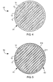
- a carbon composite sheet 30 can have carbon fibers 31 aligned substantially in a single direction A1. As shown in support structure 40 in FIG. 4 , carbon fibers 31 can be aligned such that the carbon fibers 31 in the carbon composite material are directionally aligned with a longitudinal axis A1 of the plurality of ribs 11 across the aperture.
- the carbon fibers 31 in the carbon composite material can be directionally aligned with a longitudinal axis of the plurality of ribs 11. In one embodiment, all of the carbon fibers 31 can be directionally aligned with a longitudinal axis of the plurality of ribs 11. In another embodiment, substantially all of the carbon fibers 31 can be directionally aligned with a longitudinal axis of the plurality of ribs 11. In another embodiment, at least 80% of the carbon fibers 31 can be directionally aligned with a longitudinal axis of the plurality of ribs 11. In another embodiment, at least 60% of the carbon fibers 31 can be directionally aligned with a longitudinal axis of the plurality of ribs 11.
- the carbon fibers 31 can comprise solid structures having a length that is at least 5 times greater than a diameter of the carbon fibers in one embodiment, a length that is at least 10 times greater than a diameter of the carbon fibers in another embodiment, a length that is at least 100 times greater than a diameter of the carbon fibers in another embodiment, or a length that is at least 1000 times greater than a diameter of the carbon fibers in another embodiment.
- carbon composite material in a support structure can comprise a stack of at least two carbon composite sheets. Carbon fibers 31 in at least one sheet in the stack can be directionally aligned in a different direction from carbon fibers 31 in at least one other sheet in the stack.
- support structure 50 shown in FIG. 5 includes a carbon composite sheet with carbon fibers 31a aligned in one direction A1 and at least one carbon composite sheet with carbon fibers 31b aligned in another direction A2.
- the support frame 12 can be made from the same carbon composite sheet(s) as the ribs 11, or the support frame 12 can be made separately from the ribs 11 and can be made from a different material.
- an angle between sheets having carbon fibers 31 aligned in different directions is at least ten degrees (
- carbon fibers in the carbon composite material can be randomly aligned.
- an initial sheet with randomly aligned carbon fibers may be used.
- many sheets can be stacked and randomly aligned. The sheets can be pressed together and cut to form the desired support structure.
- a support structure 60 can include multiple sized ribs 11 a-e.
- different ribs can have different cross-sectional sizes. This may be accomplished by cutting some ribs with larger widths w and other ribs with smaller widths w. Five different rib cross-sectional sizes are shown in FIG. 6 (11e > 11d > 11c > 11b > 11a).
- the plurality of ribs have at least two different cross-sectional sizes including at least one larger sized rib with a cross-sectional area that is at least 5% larger than a cross-sectional area of at least one smaller sized rib.
- a difference in cross-sectional area between different ribs can be at least 10%.
- a difference in cross-sectional area between different ribs can be at least 20%.
- a difference in cross-sectional area between different ribs can be at least 50%.
- Different rib cross-sectional sizes is described in U.S. Patent Application Number 13/312,531, filed on December 6, 2011 , which claims priority to provisional U.S. Patent Application Number 61/445,878, filed on February 23, 2011 , both incorporated herein by reference.
- a support structure 70 can include ribs 11 extending in different directions A3 and A4.
- one rib or group of ribs 11f can extend in one direction A3 and another rib or group of ribs 11g can extend in another direction A4.
- Ribs extending in different directions can cross perpendicularly or non-perpendicularly.
- Carbon fibers can be aligned with a longitudinal direction of the ribs.
- some of the carbon fibers can be directionally aligned with a longitudinal axis A3 of one rib or group of ribs 11f and other carbon fibers can be directionally aligned with a longitudinal axis A4 of another rib or group of ribs 11g.
- carbon fibers can be substantially aligned in one of two different directions A3 or A4.
- a support structure 80 can include ribs 11 that extend nonlinearly across the aperture 15 of the support frame 12.
- the ribs can be arranged to form a single hexagonal shaped opening or multiple hexagonal shaped openings 14a as shown in FIG. 8 .
- FIG. 9 Shown in FIG. 9 is an expanded section of ribs 11 of a support structure 90 with carbon fibers aligned in three different directions A5-7 and directionally aligned with a longitudinal axis A5-7 of at least one rib 11.
- One group of carbon fibers 31h can be directionally aligned A5 with at least one rib 11h
- another group of carbon fibers 31i can be directionally aligned A6 with at least one other rib 11i
- another group of carbon fibers 31j can be directionally aligned A7 with at least one other rib 11j.
- Hexagonal-shaped carbon composite support members, especially with carbon fibers aligned with the ribs 11, can provide a strong support structure.
- FIG. 10 Shown in FIG. 10 is a support structure 100 with carbon fibers aligned in three different directions A8-1 0 and directionally aligned with a longitudinal axis A8-1 0 of at least one rib 11.
- One group of carbon fibers 31 k can be directionally aligned A8 with at least one rib 11k
- another group of carbon fibers 31 m can be directionally aligned A9 with at least one other rib 11m
- another group of carbon fibers 31n can be directionally aligned A10 with at least one other rib 11 n.
- Triangular-shaped carbon composite support members, especially with carbon fibers aligned with the ribs 11, can provide a strong support structure.
- Choice of arrangement of ribs whether all in parallel, in hexagonal shape, in triangular shape, or other shape, can be made depending on needed strength, distance the ribs must span, type of film supported by the ribs, and manufacturability.
- a support structure 110 can include a small number of ribs 11, such as for example two ribs 11 in each of two different directions A11-12.
- the structure could include only a single rib, a single rib in each of two different directions, or a single rib in each of at least three different directions. This may be desirable for supporting a film 13 that is very strong, and only needs minimal support.
- Carbon fibers 31 p & 31o can be directionally aligned with longitudinal axes of ribs 11.
- carbon fibers 31o can be directionally aligned with a longitudinal axis A11 of ribs 11o and carbon fibers 31 p can be directionally aligned with a longitudinal axis A12 of ribs 11p.
- a support structure 120 can include multiple stacked support structures 127-128.
- a primary support structure 127 can comprise a primary support frame 12 defining a perimeter P and an aperture 15; a plurality of primary ribs 11 extending across the aperture 15.
- the primary ribs 11 can be carried by the primary support frame 12. Openings 14 can exist between the primary ribs 11.
- the ribs can comprise a carbon composite material.
- the primary support structure 127 can be made according to one of the various carbon composite support structures described herein. Tops of the primary ribs 11 can terminate substantially in a single plane 16.
- a secondary support structure 128 can be stacked on top of the primary support structure 127, and thus between the primary support structure 127 and the film 13, as shown in FIG. 12 .
- the primary support structure 127 can be stacked on top of the secondary support structure 128, and thus the primary support structure 127 can be disposed between the secondary support structure 128 and the film 13.
- the secondary support structure 128 can attach to the primary support structure 127 at a plane 16 at which primary ribs 11 terminate.
- the secondary support structure 128 can comprise a secondary support frame 122 defining a perimeter P and an aperture 125 and a plurality of secondary ribs 121 extending across the aperture 125.
- the secondary ribs 121 can be carried by the secondary support frame 122. Openings 124 can exist between the secondary ribs 121.
- the secondary support structure 128 can be disposed at least partly between the first support structure 127 and a film 13 or the secondary support structure 128 can be disposed completely between the first support structure 127 and the film 13. Tops of the secondary ribs 121 can terminate substantially in a single plane 126.
- the secondary support frame 122 and secondary support ribs 121 are integrally formed and can be made of the same material. In another embodiment, the secondary support frame 122 and secondary support ribs 121 are not integrally formed, are separately made then attached together, and can be made of different materials.
- the primary support frame 12 and the secondary support frame 122 are a single support frame and support both the primary ribs 11 and the secondary ribs 121.
- the primary support frame 12 and the secondary support frame 122 can be integrally formed and can be made of the same material.
- the primary support frame 12, the primary ribs 11, and the secondary support frame 122 can be integrally formed and can be made of the same material.
- the secondary ribs 121 can thus be supported by the primary ribs 11, the primary support frame 12, and / or the secondary support frame 122.
- primary ribs 11 comprise the support frame 122 for the secondary ribs 121.
- a primary support structure 127 can be formed, secondary ribs 121 can be formed, then the secondary ribs 121 can be placed on top of or attached to the primary support structure 127.
- An adhesive can be sprayed onto the primary or secondary support structure or both and the two support structures can be pressed and adhered together by the adhesive.
- the secondary support structure 128 comprises a polymer.
- the secondary support structure comprises photosensitive polyimide. Use of photosensitive polymers for support structures is described in U.S.A. Patent Number 5,578,360 , incorporated herein by reference.
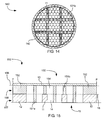
- FIGs. 13-14 show a top view of support structures 130 & 140, each with a primary and secondary support structure.
- secondary ribs 121a are supported by primary ribs 11 and by secondary support frame 132.
- secondary ribs 121b are supported by primary ribs 11 and by primary support frame 142.
- support frame 142 can serve as both primary and secondary support frame.
- support structure 150 can include multiple stacked support structures 157-158.
- a primary support structure 157 can comprise a primary support frame 12 defining a perimeter P and an aperture 15; a plurality of primary ribs 11 extending across the aperture 15.
- the primary ribs 11 can be carried by the primary support frame 12. Openings 14 can exist between the primary ribs 11.
- the ribs can comprise a carbon composite material.
- the primary support structure 157 can be made according to one of the various carbon composite support structures described herein.
- a secondary support structure 158 can be disposed at least partly on top of the primary support structure 157.
- the secondary support structure 158 can comprise a secondary support frame 152 defining a perimeter P and an aperture 155 and a plurality of secondary ribs 151 extending across the aperture 155.
- the secondary ribs 151 can be carried by the secondary support frame 158 and / or the primary ribs 11. Openings 154 can exist between the secondary ribs 151.
- the secondary support structure 158 can be disposed at least partly between the first support structure 157 and a film 13. Tops of the secondary ribs 151 can terminate substantially in a single plane 156.
- Some secondary ribs 151b can be disposed between primary ribs 11 or the primary support structure 12 and the film.
- Other ribs 151a can extend down and be disposed partly between primary ribs 11. This embodiment can be made by first creating a primary support structure 157, then pouring a liquid photosensitive polymer on top of the primary support structure 157. The photosensitive polymer can be patterned and developed to form ribs 151 and to harden the polymer.
- Stacked support structures may be useful for spanning large distances. For example, it can be impractical to use a polymer support structure to span large distances. Use of an underlying carbon composite support structure can allow the polymer support structure to span the needed large distance.
- FIG. 16 Shown in FIG. 16 is an irregular shaped support frame 162 with a perimeter P and aperture 15. Shown in FIG. 17 is support structure 170 with ribs 11 attached to irregular shaped support frame 162. Outer ribs may form the support frame.
- FIG. 18 Shown in FIG. 18 is a support structure 180 that has an opening 182 in the support frame 12. Thus the support frame 12 need not totally surround and enclose ribs 11.
- the embodiments shown in FIGs 16-18 are applicable to the various embodiments of support structures described herein.
- an x-ray detection unit 190 can include a support structure 195 according to one of the embodiments described herein.
- a film 13 can be disposed over the support structure 195.
- the support structure and the film 13 can comprise an x-ray window 196.
- the x-ray window 196 can be hermetically sealed to a mount 192.
- An x-ray detector 191 can also be attached to the mount 192.
- the mount 192 and window 196 can comprise a hermetically sealed enclosure.
- the window 196 can be configured to allow x-rays 194 to impinge upon the detector 191, such as by selecting a window 196 that will allow x-rays 194 to pass therethrough and by aligning the detector 191 with the window 194.
- the support frame 12 and the mount 192 are the same and the plurality of ribs 11 are attached to this support frame 12 and mount 192.
- the film 13 can be hermetically sealed to the mount 192 and an x-ray detector 191 can be attached to the mount.
- the x-ray window 196 and mount 192 can also be used with proportional counters, gas ionization chambers, and x-ray tubes.
- a mounted window 200 can include a film 13 disposed over a support structure 201 attached to a mount 202.
- the support structure 201 can be one of the embodiments described herein including carbon composite ribs 11.
- the film 13 can comprise a plurality of layers stacked together, including a thin film layer 203 and an outer layer 205.
- the outer layer 205 can include at least one layer of polymer, at least one layer of boron hydride, at least one layer of aluminum, or combinations of these layers.
- the thin film 203 can be comprised of a material selected from the group consisting of highly ordered pyrolytic graphite, silicon nitride, polymer, polyimide, beryllium, carbon nanotubes, carbon nanotubes embedded in a polymer, diamond, diamond-like carbon, graphene, graphene embedded in a polymer, or combinations of these various materials.
- the thin film 203, the support structure 201, or both can be hermetically sealed to a mount 202, defining a sealed joint 204.
- the outer layer 205 can extend beyond a perimeter of the thin film layer 203 and can cover the sealed joint 204.
- the outer layer 205 can provide corrosion protection to the sealed joint.
- an x-ray window 230 can be attached to a mount 231.
- the window 230 can be hermetically sealed to the mount 231.
- the x-ray window 230 can be one of the various embodiments described herein.
- the window 230 and mount 231 can enclose an interior space 232.
- the interior space 232 can be a vacuum.
- the plurality of ribs 11 can be disposed between the film 13 and the interior space 232.
- the film 13 can be disposed between the plurality of ribs 11 and the interior space 232, thus the plurality of ribs 11 can be separated from the interior space 232 by the film 13.
- ribs 11 between the film 13 and the interior space 232 can allow for easier support of the film 13, but this embodiment may have a disadvantage of certain carbon composite material components outgassing into the vacuum of the interior space 232, thus decreasing the vacuum. Whether this problem occurs is dependent on the level of vacuum and the type of carbon composite material used.
- One way of solving the problem of carbon composite material components outgassing into the interior space 232 is to dispose the film 13 between the ribs 11 and the interior space 232.
- a difficulty of this design is that gas pressure 233 outside of the window 230 and mount 231 can press the film 13 away from the support structure 12 and / or ribs 11. Thus, a stronger bond between the film 13 and the ribs 11 and / or support structure 12 may be needed for the embodiment of FIG. 24 .
- This stronger bond between the film 13 and the ribs 11 and / or support structure 12 can be achieved by use of polyimide or other high strength adhesive.
- the adhesive may need to be selected to achieve desired temperatures to which the window will be subjected. An adhesive which will not outgas may also need to be selected.
- the bond between the film 13 and the ribs 11 and / or support structure 12 may be improved by treating the surface of the ribs 11, support structure 12, and / or film 13 prior to joining the surfaces.
- the surface treatment can include use of a potassium hydroxide solution or an oxygen plasma.
- Another method of solving the problem of carbon composite material outgassing into the interior space 232 is to select carbon composite materials that will not outgas, or will have minimal outgassing.
- a carbon composite material including carbon fibers embedded in a matrix comprising polyimide and / or bismaleimide may be preferable due to low outgassing.
- Polyimide and bismaleimide are also suitable due to their ability to withstand high temperatures and their structural strength.
- the plurality of ribs 11r can be substantially straight and parallel with respect to one another and arrayed across the aperture of the support frame.
- the windows 250 and 260 can further comprise a plurality of intermediate support cross-braces 251 extending between adjacent ribs of the plurality of ribs.
- the cross-braces 251 can span an opening between adjacent ribs without spanning the aperture of the support frame.
- the cross-braces 251 can comprise a carbon composite material.
- the plurality of cross-braces 251 can be substantially perpendicular to the plurality of ribs 11r.
- the cross-braces 251 can be laterally off-set with respect to adjacent cross-braces 251 of adjacent openings so that the cross-braces 251 are segmented and discontinuous with respect to one another.
- central cross braces 251a are disposed between alternating pairs of ribs 11r and disposed at approximately a midpoint across the aperture 14; outer cross braces 251b are disposed between alternating pairs of ribs 11r and offset from the midpoint across the aperture 14.
- central cross braces 251a and outer cross braces 251b are both disposed between alternating pairs of ribs 11r, but the central cross braces 251a are disposed between different alternating pairs of ribs 11r than the outer cross braces 251 b.
- the cross-braces 251 can be disposed at approximately one third of a distance in a straight line parallel with the ribs from the support frame across the aperture.
- the cross-braces 251 can be laterally off-set with respect to adjacent cross-braces 251 of adjacent openings so that the cross-braces 251 can be segmented and discontinuous with respect to one another.
- upper cross braces 251c (called upper due to their position in the upper part of the figure) can be disposed between alternating pairs of ribs 11r and disposed at approximately one third of the distance across the aperture 14.
- Lower cross braces 251d (called lower due to their position in the lower part of the figure) can be disposed between alternating pairs of ribs 11r, different from the alternating pairs of ribs 11r between which upper cross braces 251c are disposed.
- Lower cross braces 251d can be disposed at a one third distance across the aperture 14, but this one third distance is from an opposing side of the aperture from the upper cross braces 251 c.
- Carbon composite sheets (or a single sheet) can be used to make a carbon composite wafer. Due to the toughness of carbon composite material, it can be difficult to cut the small ribs required for an x-ray window. Ribs can be cut into the wafer, in a desired pattern, by laser mill (also called laser ablation or laser cutting).
- the optimal matrix material can be selected based on the application.
- a carbon composite material including carbon fibers embedded in a matrix comprising polyimide and / or bismaleimide may be preferable due to low outgassing, ability to withstand high temperatures, and high structural strength.
- a composite with carbon fibers with sufficient length can be selected to improve structural strength. Carbon fibers that extend across the entire aperture of the window may be preferred for some applications.
- Carbon composite sheet(s) can comprise carbon fibers embedded in a matrix.
- the matrix can comprise a polymer, such as polyimide.
- the matrix can comprise bismaleimide.
- the matrix can comprise amorphous carbon or hydrogenated amorphous carbon.
- the matrix can comprise a ceramic.
- the ceramic can comprise silicon nitride, boron nitride, boron carbide, or aluminum nitride.
- carbon fibers can comprise 10-40 volumetric percent of the total volume of the carbon composite material and the matrix can comprise the remaining volumetric percent. In another embodiment, carbon fibers can comprise 40-60 volumetric percent of the total volume of the carbon composite material and the matrix can comprise the remaining volumetric percent. In another embodiment, carbon fibers can comprise 60-80 volumetric percent of the total volume of the carbon composite material and the matrix can comprise the remaining volumetric percent. Carbon fibers in the carbon composite can be substantially straight.
- a carbon wafer can be formed by pressing, at an elevated temperature, such as in an oven for example, at least one carbon composite sheet between pressure plates.
- rollers can be used to press the sheets.
- the pressure plates or rollers can be heated in order to heat the sheets.
- the sheets can be heated to at least 50 °C.
- a single sheet or multiple sheets may be used.
- Carbon fibers in the carbon composite sheet(s) can be randomly aligned, can be aligned in a single direction, can be aligned in two different directions, can be aligned in three different directions, or can be aligned in more than three different directions.
- a layer of polyimide can be bonded (such as with pressure) to one surface of the carbon composite sheet(s) prior to pressing the sheets.
- the polyimide layer can be placed between carbon composite sheets, or on an outer face of a stack of carbon composite sheets.
- the polyimide layer can be cut along with the carbon composite sheet(s) into ribs and can remain as a permanent part of the final support structure.
- the layer of polyimide film can be between 5 and 20 micrometers thick in one embodiment.
- One purpose of the polyimide layer is to make one side of the carbon composite sheet(s) smooth and flat, allowing for easier bonding of the x-ray window film. Another purpose is to improve final rib strength.
- the layer of polyimide can be replaced by another suitable polymer. High temperature resistance and high strength are two desirable characteristics of the polymer.
- carbon fibers of a single sheet, or carbon fibers of all sheets in a stack are aligned in a single direction.
- a first group of ribs, or a single rib can be cut such that a longitudinal axis of the rib(s) is aligned in the direction of the carbon fibers.
- At least two carbon composite sheets are stacked and pressed into the wafer. Carbon fibers of at least one sheet are aligned in a first direction and carbon fibers of at least one other sheet are aligned in a second direction.
- a first group of ribs, or a single rib can be cut having a longitudinal axis in the first direction to align with the carbon fibers aligned in the first direction and a second group of ribs, or a single rib, can be cut having a longitudinal axis in the second direction to align with the carbon fibers aligned in the second direction.
- an angle between the two different directions is least 10 degrees. In another embodiment, an angle between the two different directions is least 60 degrees. In another embodiment, an angle between the two different directions is about 90 degrees.
- At least three carbon composite sheets are stacked and pressed into the wafer. Carbon fibers of at least one sheet are aligned in a first direction, carbon fibers of at least one sheet are aligned in a second direction, and carbon fibers of at least one sheet are aligned in a third direction.
- a first group of ribs, or a single rib can be cut having a longitudinal axis in the first direction to align with the carbon fibers aligned in the first direction
- a second group of ribs, or a single rib can be cut having a longitudinal axis in the second direction to align with the carbon fibers aligned in the second direction
- a third group of ribs, or a single rib can be cut having a longitudinal axis in the third direction to align with the carbon fibers aligned in the third direction.
- An angle between any two directions can be about 120 degrees.
- the structure can form hexagonal-shaped or triangular-shaped openings.
- each carbon composite sheet in a stack can have a thickness of between 20 to 350 micrometers ( ⁇ m).
- the plates used for pressing the carbon composite sheets into a wafer can have non-stick surfaces facing the sheet(s) of carbon composite.
- the plates can have fluorinated flat silicon surfaces facing the sheets.
- FIG. 21 shows a press 210 including two plates 211 and at least one carbon composite sheet 212 between the two plates 211.
- the carbon composite sheet(s) 212 can include a layer of polyimide or other polymer.
- Pressure P can be applied to the carbon composite sheet(s) 212 and the carbon composite sheet(s) (and optionally a layer of polymer, such as polyimide) can be heated to a temperature of at least 50 °C to cure the sheet(s) of carbon composite into a carbon composite wafer. Temperature, pressure, and time can be adjusted based on thicknesses of the sheets, the number of sheets, matrix material, and desired final characteristics of the wafer. For example, carbon composite sheets comprising carbon fibers in a polyimide matrix have been made into wafers at pressures of 200 - 3000 psi, temperatures of 120 - 200 °C, and initial sheet thickness of 180 micrometer ( ⁇ m).
- the wafer can be removed from the press and the wafer can be cut to form ribs and / or support frame.
- the wafer may be cut by laser milling or laser ablation.
- a high power laser can use short pulses of laser to ablate the material to form the openings by ultrafast laser ablation.
- a femtosecond laser may be used.
- Ablating wafer material in short pulses of high power laser can be used in order to avoid overheating the polymer material in the carbon composite.
- a non-pulsing laser can be used and the wafer can be cooled by other methods, such as conductive or convective heat removal.
- the wafer can be cooled by water flow or air across the wafer.
- the above mentioned cooling methods can also be used with laser pulses, such as a femtosecond laser, if additional cooling is needed.
- the ribs, formed by the laser, can be formed of a single original layer of carbon composite material or multiple layers of carbon composite material and can include at least one layer of polyimide. If a polyimide layer is used in the stack, then the ribs can comprise carbon composite and polyimide and thus polyimide ribs will be attached to and aligned with the carbon composite ribs.
- ribs 11 can be formed separately from the support structure 12. Ribs 11 can then be laid on top of the support frame 12. An adhesive may be used to hold the ribs in place.
- the support frame 12 can be a ring a material or a mount, such as mount 192 shown in FIG. 19 or mount 202 shown in FIG. 20 .
Abstract
Description
- It is important for support members in support structures, such as x-ray window support structures, to be strong but also small in size. Support structures in x-ray windows can support a film. X-ray windows can be used for enclosing an x-ray source or detection device. X-ray windows can be used to separate a pressure differential, such as ambient air pressure on one side of the window and a vacuum on an opposing side, while allowing passage of x-rays through the window.
- X-ray windows can include a thin film supported by the support structure, typically comprised of ribs supported by a frame. The support structure can be used to minimize sagging or breaking of the thin film. The support structure can interfere with the passage of x-rays and thus it can be desirable for ribs to be as thin or narrow as possible while still maintaining sufficient strength to support the thin film. The support structure and film are normally expected to be strong enough to withstand a differential pressure of around 1 atmosphere without sagging or breaking.
- Materials comprising Silicon have been use as support structures. A wafer of such material can be etched to form the support structure.
- Information relevant to x-ray windows can be found in
U.S. Patent Numbers 4,933,557 ,7,737,424 ,7,709,820 ,7,756,251 andU.S. ,Patent Application Numbers 11/756,96212/783,707 12/899,750 13/018,667 61/408,472 61/445,878 61/408,472 - It has been recognized that it would be advantageous to provide a support structure that is strong. For x-ray windows, it has been recognized that it would be advantageous to provide a support structure that minimizes attenuation of x-rays. The present invention is directed to support structures, and methods of making support structures, that satisfy these needs.
- In one embodiment, the apparatus comprises a support frame defining a perimeter and an aperture and a plurality of ribs comprising a carbon composite material extending across the aperture of the support frame and carried by the support frame. Openings exist between the plurality of ribs. A film can be disposed over, carried by, and span the plurality of ribs and can be disposed over and span the openings. The film can be configured to pass radiation therethrough.
- In another embodiment, a method of making a carbon composite support structure comprises pressing at least one sheet of carbon composite between non-stick surfaces of pressure plates and heating the sheet(s) to at least 50 °C to cure the sheet(s) into a carbon composite wafer. Each sheet can have a thickness of between 20 to 350 micrometers (µm). The wafer can then be removed and a plurality of openings can be laser cut in the wafer, forming ribs.
-
-
FIG. 1 is a schematic cross-sectional side view of a carbon composite support structure, in accordance with an embodiment of the present invention; -
FIG. 2 is a schematic cross-sectional side view of a carbon composite support structure, in accordance with an embodiment of the present invention; -
FIG. 3 is a schematic top view of a carbon composite wafer in accordance with an embodiment of the present invention; -
FIG. 4 is a schematic top view of a carbon composite support structure, wherein carbon fibers in a carbon composite material are directionally aligned with a longitudinal axis of a plurality of ribs across an aperture of a support frame, in accordance with an embodiment of the present invention; -
FIG. 5 is a schematic top view of a carbon composite support structure comprising a carbon composite material that includes carbon fibers directionally aligned in two different directions; in accordance with an embodiment of the present invention; -
FIG. 6 is a schematic top view of a carbon composite support structure with ribs that have at least two different cross-sectional sizes, in accordance with an embodiment of the present invention; -
FIG. 7 is a schematic top view of a carbon composite support structure with intersecting ribs, in accordance with an embodiment of the present invention; -
FIG. 8 is a schematic top view of a carbon composite support structure with hexagonal shaped openings and hexagonal shaped ribs, in accordance with an embodiment of the present invention; -
FIG. 9 is a schematic top view of a section of a carbon composite support structure with a hexagonal shaped opening, hexagonal shaped ribs, and carbon fibers directionally aligned with longitudinal axes of the ribs, in accordance with an embodiment of the present invention; -
FIG. 10 is a schematic top view of a carbon composite support structure with triangular shaped openings, triangular shaped ribs, and carbon fibers directionally aligned with longitudinal axes of the ribs, in accordance with an embodiment of the present invention; -
FIG. 11 is a schematic top view of a carbon composite support structure with two ribs extending in one direction and two ribs extending in a different direction and carbon fibers that are directionally aligned with longitudinal axes of the ribs, in accordance with an embodiment of the present invention; -
FIG. 12 is a schematic cross-sectional side view of multiple stacked support structures, including a carbon composite support structure, in accordance with an embodiment of the present invention; -
FIG. 13 is a schematic top view of a stacked support structure including a carbon composite support structure, in accordance with an embodiment of the present invention; -
FIG. 14 is a schematic top view of a stacked support structure including a carbon composite support structure, in accordance with an embodiment of the present invention; -
FIG. 15 is a schematic cross-sectional side view of a multi-layer support structure including a carbon composite support structure, in accordance with an embodiment of the present invention; -
FIG. 16 is a schematic top view of an irregular-shaped support frame, in accordance with an embodiment of the present invention; -
FIG. 17 is a schematic top view of a support structure with an irregular-shaped support frame, in accordance with an embodiment of the present invention; -
FIG. 18 is a schematic top view of a support structure with a support frame that does not completely surround or enclose the ribs, in accordance with an embodiment of the present invention; -
FIG. 19 is a schematic cross-sectional side view of an x-ray detector, in accordance with an embodiment of the present invention; -
FIG. 20 is a schematic cross-sectional side view of an x-ray window attached to a mount, in accordance with an embodiment of the present invention; -
FIG. 21 is a schematic cross-sectional side view showing pressing and heating at least one sheet of carbon composite to form a carbon composite wafer, in accordance with an embodiment of the present invention; -
FIG. 22 is a schematic top view of ribs disposed over and supported by a support frame, in accordance with an embodiment of the present invention; -
FIG. 23 is a schematic cross-sectional side view of an x-ray window attached to a mount, with the support frame facing the interior of the mount; in accordance with an embodiment of the present invention; -
FIG. 24 is a schematic cross-sectional side view of an x-ray window attached to a mount, with the support frame facing the exterior of the mount; in accordance with an embodiment of the present invention; -
FIG. 25 is a schematic top view of a carbon composite support structure, including a plurality of cross-braces disposed between a plurality of ribs, in accordance with an embodiment of the present invention; -
FIG. 26 is a schematic top view of a carbon composite support structure, including a plurality of cross-braces disposed between a plurality of ribs, in accordance with an embodiment of the present invention. -
- • As used herein, the terms "about" or "approximately" are used to provide flexibility to a numerical value or range by providing that a given value may be "a little above" or "a little below" the endpoint.
- • As used herein, the term "carbon fiber" or "carbon fibers" means solid, substantially cylindrically shaped structures having a mass fraction of at least 85% carbon, a length of at least 5 micrometers and a diameter of at least 1 micrometer.
- • As used herein, the term "directionally aligned," in referring to alignment of carbon fibers with ribs, means that the carbon fibers are substantially aligned with a longitudinal axis of the ribs and does not require the carbon fibers to be exactly aligned with a longitudinal axis of the ribs.
- • As used herein, the term "rib" means a support member and can extend, linearly or with bends or curves, by itself or coupled with other ribs, across an aperture of a support frame.
- • As used herein, the term "substantially" refers to the complete or nearly complete extent or degree of an action, characteristic, property, state, structure, item, or result. For example, an object that is "substantially" enclosed would mean that the object is either completely enclosed or nearly completely enclosed. The exact allowable degree of deviation from absolute completeness may in some cases depend on the specific context. However, generally speaking the nearness of completion will be so as to have the same overall result as if absolute and total completion were obtained. The use of "substantially" is equally applicable when used in a negative connotation to refer to the complete or near complete lack of an action, characteristic, property, state, structure, item, or result.
- Reference will now be made to the exemplary embodiments illustrated in the drawings, and specific language will be used herein to describe the same. It will nevertheless be understood that no limitation of the scope of the invention is thereby intended. Alterations and further modifications of the inventive features illustrated herein, and additional applications of the principles of the inventions as illustrated herein, which would occur to one skilled in the relevant art and having possession of this disclosure, are to be considered within the scope of the invention.
- As illustrated in
FIG. 1 , asupport structure 10 is shown comprising asupport frame 12 and a plurality ofribs 11. Thesupport frame 12 can include a perimeter P and anaperture 15. The plurality ofribs 11 can comprise a carbon composite material and can extend across theaperture 15 of thesupport frame 12 and can be carried by thesupport frame 12.Openings 14 can exist between the plurality ofribs 11. Tops of theribs 11 can terminate substantially in acommon plane 16. - The carbon composite material can comprise carbon fibers embedded in a matrix. The carbon fibers can comprise a carbon mass fraction of at least 85% in one embodiment, at least 88% in another embodiment, at least 92% in another embodiment, or 100% in another embodiment. The carbon fibers can comprise carbon atoms connected to other carbon atoms by sp2 bonding. The carbon fibers can have a diameter of at least 1 micrometer in one embodiment, at least 3 micrometers in another embodiment, or at least 5 micrometers in another embodiment. Most, substantially all, or all of the carbon fibers can have a length of at least 1 micrometer in one embodiment, at least 10 micrometers in another embodiment, at least 100 micrometers in another embodiment, at least 1 millimeter in another embodiment, or at least 5 millimeters in another embodiment. Most, at least 80%, substantially all, or all of the carbon fibers can be aligned with a rib. Most, at least 80%, substantially all, or all of the carbon fibers can have a length that is at least half the length of the rib with which it is aligned in one embodiment, or at least as long as the rib with which it is aligned in another embodiment. The carbon fibers can be substantially straight.
- In one embodiment, such as if the support structure is used as an x-ray window, a
film 13 can be disposed over, carried by, and span the plurality ofribs 11 and can be disposed over and span theopenings 14. Thefilm 13 can be configured to pass radiation therethrough. For example, thefilm 13 can be made of a material that has a low atomic number and can be thin, such as for example about 5 to 500 micrometers (µm). Thefilm 13 can have sufficient strength to allow differential pressure of at least one atmosphere without breaking. Thefilm 13 can be hermetic or air-tight. Thefilm 13 can combine with one of the support structures described herein and a shell to form a hermetic enclosure. - The
film 13 can comprise highly ordered pyrolytic graphite, silicon nitride, polymer, polyimide, beryllium, carbon nanotubes, carbon nanotubes embedded in a polymer, diamond, diamond-like carbon, graphene, graphene embedded in a polymer, boron hydride, aluminum, or combinations of these various materials. Thefilm 13 can include a stack of layers, and different layers in the stack can comprise different materials. - In one embodiment, the
film 13 comprises a plurality of layers stacked together, including an aluminum layer disposed over a thin film layer comprising a material selected from the group consisting of highly ordered pyrolytic graphite, silicon nitride, polymer, polyimide, beryllium, carbon nanotubes, carbon nanotubes embedded in a polymer, diamond, diamond-like carbon, graphene, graphene embedded in a polymer, boron hydride, and combinations thereof. Aluminum can be a gas barrier in order to provide a hermetic film. Aluminum can be used to prevent visible light from passing through the window. In one embodiment, the aluminum layer can have a thickness of between 10 to 60 nanometers. - The
film 13 can include a protective layer over the aluminum layer. The protective layer can provide corrosion protection for the aluminum. The protective layer can comprise amino phosphonate, silicon nitride, silicon dioxide, borophosphosilicate glass, fluorinated hydrocarbon, polymer, bismaleimide, silane, fluorine, or combinations thereof. The protective layer can be applied by chemical vapor deposition, atomic layer deposition, sputter, immersion, or spray. A polymer protective layer can comprise polyimide. Use of amino phosphonate as a protective layer is described inU.S.A. Patent Number 6,785,050 , incorporated herein by reference. - In some applications, such as analysis of x-ray fluorescence, it can be desirable for the
film 13 to comprise elements having low atomic numbers such as hydrogen (1), beryllium (4), boron (5), and carbon (6). The following materials consist of, or include a large percent of, the low atomic number elements hydrogen, beryllium, boron, and carbon: highly ordered pyrolytic graphite, polymer, beryllium, carbon nanotubes, carbon nanotubes embedded in a polymer, diamond, diamond-like carbon, graphene, graphene embedded in a polymer, and boron hydride. - In one embodiment, the
support frame 12 comprises a carbon composite material. Thesupport frame 12 and the plurality ofribs 11 can be integrally formed together from at least one layer of carbon composite material. As shown inFIG. 1 , thesupport frame 12 and the plurality ofribs 11 can have substantially the same thickness t1, - As shown in
FIG. 2 , the plurality ofribs 11 andsupport frame 12 can be separately formed, can be formed of separate materials and / or can have different thicknesses (t2 ≠ t3). In one embodiment, a thickness t3 of thesupport frame 12 can be at least 10% thicker than a thickness t2 of the ribs 11
support frame 12 can be at least 20% thicker than a thickness t2 of the ribs 11
support frame 12 can be at least 50% thicker than a thickness t2 of the ribs 11
- For simplicity of manufacture, it can be desirable to form the
ribs 11 and thesupport frame 12 in a single step from a single wafer of carbon composite, as shown inFIG. 1 . In one embodiment, thesupport frame 12 and the plurality ofribs 11 were integrally formed together from at least one layer of carbon composite material. Having thesupport frame 12 and the plurality ofribs 11 integrally formed together from at least one layer of carbon composite material can be beneficial for simplicity of manufacturing. For astronger support frame 12 compared to theribs 11, it can be desirable to form theribs 11 and support structure separately and have athicker support structure 12, as shown inFIG. 2 . - In one embodiment, the
ribs 11 and / orsupport frame 12 can have a thickness t of between 20 to 350 micrometers (µm) and / or a width of between 20 to 100 micrometers (µm). In another embodiment, theribs 11 and / orsupport frame 12 can have a thickness t of between 10 to 300 micrometers (µm) and / or a width w of between 10 - 200 micrometers (µm). In one embodiment, a spacing S betweenadjacent ribs 11 can be between 100 to 700 micrometers (µm). In another embodiment, a spacing S between adjacent ribs can be between 700 micrometers (µm) and 1 millimeter (mm). In another embodiment, a spacing S between adjacent ribs can be between 1 millimeter and 10 millimeters. A larger spacing S allows x-rays to more easily pass through the window but also provides less support for thefilm 13. A smaller spacing S may result in increased, undesirable attenuation of x-rays but also provides greater support for thefilm 13. - Use of carbon composite material, which can have high strength, in a support structure, can allow a high percentage of open area within the
support frame 12 and/or reduce the overall height ofribs 11, both of which are desirable characteristics because both increase the ability of the window to pass radiation. Theopenings 14 can occupy more area within the perimeter P of thesupport frame 12 than the plurality ofribs 11 in one embodiment. In various embodiments, theopenings 14 can occupy greater than 70%, greater than 90%, between 70% to 90%, between 85% to 95%, between 90% to 99%, or between 99% to 99.9% of the area within the perimeter P of thesupport frame 12 than the plurality ofribs 11. - Embodiments with openings occupying a very large percent of the area within the perimeter P of the
support frame 12 may be used in an application in which a strong film is used and only needs minimal support. Such embodiments may also be used in an application in which at least one additional support structure, such as an additional polymer support structure, is disposed between the carbon composite support structure and thefilm 13. - As shown in
FIG. 3 , acarbon composite sheet 30 can havecarbon fibers 31 aligned substantially in a single direction A1. As shown insupport structure 40 inFIG. 4 ,carbon fibers 31 can be aligned such that thecarbon fibers 31 in the carbon composite material are directionally aligned with a longitudinal axis A1 of the plurality ofribs 11 across the aperture. - In various figures and embodiments, the
carbon fibers 31 in the carbon composite material can be directionally aligned with a longitudinal axis of the plurality ofribs 11. In one embodiment, all of thecarbon fibers 31 can be directionally aligned with a longitudinal axis of the plurality ofribs 11. In another embodiment, substantially all of thecarbon fibers 31 can be directionally aligned with a longitudinal axis of the plurality ofribs 11. In another embodiment, at least 80% of thecarbon fibers 31 can be directionally aligned with a longitudinal axis of the plurality ofribs 11. In another embodiment, at least 60% of thecarbon fibers 31 can be directionally aligned with a longitudinal axis of the plurality ofribs 11. - The
carbon fibers 31 can comprise solid structures having a length that is at least 5 times greater than a diameter of the carbon fibers in one embodiment, a length that is at least 10 times greater than a diameter of the carbon fibers in another embodiment, a length that is at least 100 times greater than a diameter of the carbon fibers in another embodiment, or a length that is at least 1000 times greater than a diameter of the carbon fibers in another embodiment. - In one embodiment, carbon composite material in a support structure can comprise a stack of at least two carbon composite sheets.
Carbon fibers 31 in at least one sheet in the stack can be directionally aligned in a different direction fromcarbon fibers 31 in at least one other sheet in the stack. For example,support structure 50 shown inFIG. 5 includes a carbon composite sheet withcarbon fibers 31a aligned in one direction A1 and at least one carbon composite sheet withcarbon fibers 31b aligned in another direction A2. In the various embodiments described herein, thesupport frame 12 can be made from the same carbon composite sheet(s) as theribs 11, or thesupport frame 12 can be made separately from theribs 11 and can be made from a different material. - In one embodiment, an angle between sheets having
carbon fibers 31 aligned in different directions is at least ten degrees (|A2 - A1| > 10 degrees), In another embodiment, an angle between sheets havingcarbon fibers 31 aligned in different directions is at least thirty degrees (|A2 - A1| > 30 degrees). In another embodiment, an angle between sheets havingcarbon fibers 31 aligned in different directions is at least forty five degrees (|A2 - A1| > 45 degrees). In another embodiment, an angle between sheets havingcarbon fibers 31 aligned in different directions is at least sixty degrees (|A2 - A1| > 60 degrees). - In another embodiment, carbon fibers in the carbon composite material can be randomly aligned. For example, an initial sheet with randomly aligned carbon fibers may be used. Alternatively, many sheets can be stacked and randomly aligned. The sheets can be pressed together and cut to form the desired support structure.
- As shown in
FIG. 6 , asupport structure 60 can include multiplesized ribs 11 a-e. For example, different ribs can have different cross-sectional sizes. This may be accomplished by cutting some ribs with larger widths w and other ribs with smaller widths w. Five different rib cross-sectional sizes are shown inFIG. 6 (11e > 11d > 11c > 11b > 11a). - In one embodiment, the plurality of ribs have at least two different cross-sectional sizes including at least one larger sized rib with a cross-sectional area that is at least 5% larger than a cross-sectional area of at least one smaller sized rib. In another embodiment, a difference in cross-sectional area between different ribs can be at least 10%. In another embodiment, a difference in cross-sectional area between different ribs can be at least 20%. In another embodiment, a difference in cross-sectional area between different ribs can be at least 50%. Different rib cross-sectional sizes is described in
U.S. Patent Application Number 13/312,531, filed on December 6, 2011U.S. Patent Application Number 61/445,878, filed on February 23, 2011 - As shown in
FIG. 7 , asupport structure 70 can includeribs 11 extending in different directions A3 and A4. For example, one rib or group ofribs 11f can extend in one direction A3 and another rib or group of ribs 11g can extend in another direction A4. Ribs extending in different directions can cross perpendicularly or non-perpendicularly. Carbon fibers can be aligned with a longitudinal direction of the ribs. For example, inFIG. 7 , some of the carbon fibers can be directionally aligned with a longitudinal axis A3 of one rib or group ofribs 11f and other carbon fibers can be directionally aligned with a longitudinal axis A4 of another rib or group of ribs 11g. In one embodiment, carbon fibers can be substantially aligned in one of two different directions A3 or A4. - As shown in
FIG. 8 , asupport structure 80 can includeribs 11 that extend nonlinearly across theaperture 15 of thesupport frame 12. The ribs can be arranged to form a single hexagonal shaped opening or multiple hexagonal shapedopenings 14a as shown inFIG. 8 . - Shown in
FIG. 9 is an expanded section ofribs 11 of asupport structure 90 with carbon fibers aligned in three different directions A5-7 and directionally aligned with a longitudinal axis A5-7 of at least onerib 11. One group ofcarbon fibers 31h can be directionally aligned A5 with at least onerib 11h, another group ofcarbon fibers 31i can be directionally aligned A6 with at least oneother rib 11i, and another group of carbon fibers 31j can be directionally aligned A7 with at least oneother rib 11j. Hexagonal-shaped carbon composite support members, especially with carbon fibers aligned with theribs 11, can provide a strong support structure. - Shown in
FIG. 10 is asupport structure 100 with carbon fibers aligned in three different directions A8-1 0 and directionally aligned with a longitudinal axis A8-1 0 of at least onerib 11. One group ofcarbon fibers 31 k can be directionally aligned A8 with at least onerib 11k, another group ofcarbon fibers 31 m can be directionally aligned A9 with at least oneother rib 11m, and another group ofcarbon fibers 31n can be directionally aligned A10 with at least oneother rib 11 n. Triangular-shaped carbon composite support members, especially with carbon fibers aligned with theribs 11, can provide a strong support structure. - Choice of arrangement of ribs, whether all in parallel, in hexagonal shape, in triangular shape, or other shape, can be made depending on needed strength, distance the ribs must span, type of film supported by the ribs, and manufacturability.
- As shown in
FIG. 11 , asupport structure 110 can include a small number ofribs 11, such as for example tworibs 11 in each of two different directions A11-12. Alternatively, the structure could include only a single rib, a single rib in each of two different directions, or a single rib in each of at least three different directions. This may be desirable for supporting afilm 13 that is very strong, and only needs minimal support.Carbon fibers 31 p & 31o can be directionally aligned with longitudinal axes ofribs 11. For example, as shown inFIG. 11 , carbon fibers 31o can be directionally aligned with a longitudinal axis A11 of ribs 11o andcarbon fibers 31 p can be directionally aligned with a longitudinal axis A12 ofribs 11p. - Shown in
FIG. 12 , asupport structure 120 can include multiple stacked support structures 127-128. Aprimary support structure 127 can comprise aprimary support frame 12 defining a perimeter P and anaperture 15; a plurality ofprimary ribs 11 extending across theaperture 15. Theprimary ribs 11 can be carried by theprimary support frame 12.Openings 14 can exist between theprimary ribs 11. The ribs can comprise a carbon composite material. Theprimary support structure 127 can be made according to one of the various carbon composite support structures described herein. Tops of theprimary ribs 11 can terminate substantially in asingle plane 16. - A
secondary support structure 128 can be stacked on top of theprimary support structure 127, and thus between theprimary support structure 127 and thefilm 13, as shown inFIG. 12 . Alternatively, theprimary support structure 127 can be stacked on top of thesecondary support structure 128, and thus theprimary support structure 127 can be disposed between thesecondary support structure 128 and thefilm 13. Thesecondary support structure 128 can attach to theprimary support structure 127 at aplane 16 at whichprimary ribs 11 terminate. - The
secondary support structure 128 can comprise asecondary support frame 122 defining a perimeter P and anaperture 125 and a plurality ofsecondary ribs 121 extending across theaperture 125. Thesecondary ribs 121 can be carried by thesecondary support frame 122.Openings 124 can exist between thesecondary ribs 121. Thesecondary support structure 128 can be disposed at least partly between thefirst support structure 127 and afilm 13 or thesecondary support structure 128 can be disposed completely between thefirst support structure 127 and thefilm 13. Tops of thesecondary ribs 121 can terminate substantially in asingle plane 126. - In one embodiment, the
secondary support frame 122 andsecondary support ribs 121 are integrally formed and can be made of the same material. In another embodiment, thesecondary support frame 122 andsecondary support ribs 121 are not integrally formed, are separately made then attached together, and can be made of different materials. - In another embodiment, the
primary support frame 12 and thesecondary support frame 122 are a single support frame and support both theprimary ribs 11 and thesecondary ribs 121. Theprimary support frame 12 and thesecondary support frame 122 can be integrally formed and can be made of the same material. Theprimary support frame 12, theprimary ribs 11, and thesecondary support frame 122 can be integrally formed and can be made of the same material. Thesecondary ribs 121 can thus be supported by theprimary ribs 11, theprimary support frame 12, and / or thesecondary support frame 122. - In one embodiment,
primary ribs 11 comprise thesupport frame 122 for thesecondary ribs 121. For example, aprimary support structure 127 can be formed,secondary ribs 121 can be formed, then thesecondary ribs 121 can be placed on top of or attached to theprimary support structure 127. An adhesive can be sprayed onto the primary or secondary support structure or both and the two support structures can be pressed and adhered together by the adhesive. - In one embodiment, the
secondary support structure 128 comprises a polymer. In another embodiment, the secondary support structure comprises photosensitive polyimide. Use of photosensitive polymers for support structures is described inU.S.A. Patent Number 5,578,360 , incorporated herein by reference. -
FIGs. 13-14 show a top view ofsupport structures 130 & 140, each with a primary and secondary support structure. InFIG. 13 ,secondary ribs 121a are supported byprimary ribs 11 and bysecondary support frame 132. InFIG. 14 ,secondary ribs 121b are supported byprimary ribs 11 and byprimary support frame 142. Thus,support frame 142 can serve as both primary and secondary support frame. - Shown in
FIG. 15 ,support structure 150 can include multiple stacked support structures 157-158. Aprimary support structure 157 can comprise aprimary support frame 12 defining a perimeter P and anaperture 15; a plurality ofprimary ribs 11 extending across theaperture 15. Theprimary ribs 11 can be carried by theprimary support frame 12.Openings 14 can exist between theprimary ribs 11. The ribs can comprise a carbon composite material. Theprimary support structure 157 can be made according to one of the various carbon composite support structures described herein. - A
secondary support structure 158 can be disposed at least partly on top of theprimary support structure 157. Thesecondary support structure 158 can comprise asecondary support frame 152 defining a perimeter P and anaperture 155 and a plurality of secondary ribs 151 extending across theaperture 155. The secondary ribs 151 can be carried by thesecondary support frame 158 and / or theprimary ribs 11.Openings 154 can exist between the secondary ribs 151. Thesecondary support structure 158 can be disposed at least partly between thefirst support structure 157 and afilm 13. Tops of the secondary ribs 151 can terminate substantially in asingle plane 156. - Some
secondary ribs 151b can be disposed betweenprimary ribs 11 or theprimary support structure 12 and the film.Other ribs 151a can extend down and be disposed partly betweenprimary ribs 11. This embodiment can be made by first creating aprimary support structure 157, then pouring a liquid photosensitive polymer on top of theprimary support structure 157. The photosensitive polymer can be patterned and developed to form ribs 151 and to harden the polymer. - Stacked support structures may be useful for spanning large distances. For example, it can be impractical to use a polymer support structure to span large distances. Use of an underlying carbon composite support structure can allow the polymer support structure to span the needed large distance.
- Most of the figures herein show circular support frames. Although it may be more convenient to use circular support frames, other support frame shapes may be used with the various embodiments described herein. Shown in
FIG. 16 is an irregular shapedsupport frame 162 with a perimeter P andaperture 15. Shown inFIG. 17 issupport structure 170 withribs 11 attached to irregular shapedsupport frame 162. Outer ribs may form the support frame. - Most of the figures herein show support frames which totally surround and enclose ribs. A support frame with an enclosed perimeter can provide greater strength and support for ribs and thus is a preferred embodiment; however, the various embodiments described herein are not limited to fully enclosed support frames. Shown in
FIG. 18 is asupport structure 180 that has an opening 182 in thesupport frame 12. Thus thesupport frame 12 need not totally surround and encloseribs 11. The embodiments shown inFIGs 16-18 are applicable to the various embodiments of support structures described herein. - As shown in
FIG. 19 , anx-ray detection unit 190 can include asupport structure 195 according to one of the embodiments described herein. Afilm 13 can be disposed over thesupport structure 195. The support structure and thefilm 13 can comprise anx-ray window 196. Thex-ray window 196 can be hermetically sealed to amount 192. An x-ray detector 191 can also be attached to themount 192. Themount 192 andwindow 196 can comprise a hermetically sealed enclosure. Thewindow 196 can be configured to allowx-rays 194 to impinge upon the detector 191, such as by selecting awindow 196 that will allowx-rays 194 to pass therethrough and by aligning the detector 191 with thewindow 194. In one embodiment, thesupport frame 12 and themount 192 are the same and the plurality ofribs 11 are attached to thissupport frame 12 andmount 192. Thefilm 13 can be hermetically sealed to themount 192 and an x-ray detector 191 can be attached to the mount. Thex-ray window 196 and mount 192 can also be used with proportional counters, gas ionization chambers, and x-ray tubes. - As shown in
FIG. 20 , amounted window 200 can include afilm 13 disposed over asupport structure 201 attached to amount 202. Thesupport structure 201 can be one of the embodiments described herein includingcarbon composite ribs 11. Thefilm 13 can comprise a plurality of layers stacked together, including athin film layer 203 and anouter layer 205. Theouter layer 205 can include at least one layer of polymer, at least one layer of boron hydride, at least one layer of aluminum, or combinations of these layers. Thethin film 203 can be comprised of a material selected from the group consisting of highly ordered pyrolytic graphite, silicon nitride, polymer, polyimide, beryllium, carbon nanotubes, carbon nanotubes embedded in a polymer, diamond, diamond-like carbon, graphene, graphene embedded in a polymer, or combinations of these various materials. - The
thin film 203, thesupport structure 201, or both can be hermetically sealed to amount 202, defining a sealed joint 204. Theouter layer 205 can extend beyond a perimeter of thethin film layer 203 and can cover the sealed joint 204. Theouter layer 205 can provide corrosion protection to the sealed joint. - Shown in
FIGs. 23-24 , anx-ray window 230 can be attached to amount 231. Thewindow 230 can be hermetically sealed to themount 231. Thex-ray window 230 can be one of the various embodiments described herein. Thewindow 230 and mount 231 can enclose aninterior space 232. Theinterior space 232 can be a vacuum. - As shown in
FIG. 23 , the plurality ofribs 11 can be disposed between thefilm 13 and theinterior space 232. As shown inFIG. 24 , thefilm 13 can be disposed between the plurality ofribs 11 and theinterior space 232, thus the plurality ofribs 11 can be separated from theinterior space 232 by thefilm 13. - Having the
ribs 11 between thefilm 13 and theinterior space 232, as shown inFIG. 23 , can allow for easier support of thefilm 13, but this embodiment may have a disadvantage of certain carbon composite material components outgassing into the vacuum of theinterior space 232, thus decreasing the vacuum. Whether this problem occurs is dependent on the level of vacuum and the type of carbon composite material used. - One way of solving the problem of carbon composite material components outgassing into the
interior space 232 is to dispose thefilm 13 between theribs 11 and theinterior space 232. A difficulty of this design is thatgas pressure 233 outside of thewindow 230 and mount 231 can press thefilm 13 away from thesupport structure 12 and / orribs 11. Thus, a stronger bond between thefilm 13 and theribs 11 and / orsupport structure 12 may be needed for the embodiment ofFIG. 24 . - This stronger bond between the
film 13 and theribs 11 and / orsupport structure 12 can be achieved by use of polyimide or other high strength adhesive. The adhesive may need to be selected to achieve desired temperatures to which the window will be subjected. An adhesive which will not outgas may also need to be selected. The bond between thefilm 13 and theribs 11 and / orsupport structure 12 may be improved by treating the surface of theribs 11,support structure 12, and / orfilm 13 prior to joining the surfaces. The surface treatment can include use of a potassium hydroxide solution or an oxygen plasma. - Another method of solving the problem of carbon composite material outgassing into the
interior space 232 is to select carbon composite materials that will not outgas, or will have minimal outgassing. A carbon composite material including carbon fibers embedded in a matrix comprising polyimide and / or bismaleimide may be preferable due to low outgassing. Polyimide and bismaleimide are also suitable due to their ability to withstand high temperatures and their structural strength. - As shown on
x-ray windows FIGs. 25-26 , the plurality ofribs 11r can be substantially straight and parallel with respect to one another and arrayed across the aperture of the support frame. Thewindows ribs 11r. - The cross-braces 251 can be laterally off-set with respect to adjacent cross-braces 251 of adjacent openings so that the cross-braces 251 are segmented and discontinuous with respect to one another. For example, in
FIG. 25 ,central cross braces 251a are disposed between alternating pairs ofribs 11r and disposed at approximately a midpoint across theaperture 14; outer cross braces 251b are disposed between alternating pairs ofribs 11r and offset from the midpoint across theaperture 14. Thus, central cross braces 251a and outer cross braces 251b are both disposed between alternating pairs ofribs 11r, but thecentral cross braces 251a are disposed between different alternating pairs ofribs 11r than the outer cross braces 251 b. - The cross-braces 251 can be disposed at approximately one third of a distance in a straight line parallel with the ribs from the support frame across the aperture. The cross-braces 251 can be laterally off-set with respect to adjacent cross-braces 251 of adjacent openings so that the cross-braces 251 can be segmented and discontinuous with respect to one another. For example, in
FIG. 26 , upper cross braces 251c (called upper due to their position in the upper part of the figure) can be disposed between alternating pairs ofribs 11r and disposed at approximately one third of the distance across theaperture 14. Lower cross braces 251d (called lower due to their position in the lower part of the figure) can be disposed between alternating pairs ofribs 11r, different from the alternating pairs ofribs 11r between which upper cross braces 251c are disposed. Lower cross braces 251d can be disposed at a one third distance across theaperture 14, but this one third distance is from an opposing side of the aperture from the upper cross braces 251 c. - Carbon composite sheets (or a single sheet) can be used to make a carbon composite wafer. Due to the toughness of carbon composite material, it can be difficult to cut the small ribs required for an x-ray window. Ribs can be cut into the wafer, in a desired pattern, by laser mill (also called laser ablation or laser cutting).
- The optimal matrix material can be selected based on the application. A carbon composite material including carbon fibers embedded in a matrix comprising polyimide and / or bismaleimide may be preferable due to low outgassing, ability to withstand high temperatures, and high structural strength.
- A composite with carbon fibers with sufficient length can be selected to improve structural strength. Carbon fibers that extend across the entire aperture of the window may be preferred for some applications.
- Carbon composite sheet(s) can comprise carbon fibers embedded in a matrix. The matrix can comprise a polymer, such as polyimide. The matrix can comprise bismaleimide. The matrix can comprise amorphous carbon or hydrogenated amorphous carbon. The matrix can comprise a ceramic. The ceramic can comprise silicon nitride, boron nitride, boron carbide, or aluminum nitride.
- In one embodiment, carbon fibers can comprise 10-40 volumetric percent of the total volume of the carbon composite material and the matrix can comprise the remaining volumetric percent. In another embodiment, carbon fibers can comprise 40-60 volumetric percent of the total volume of the carbon composite material and the matrix can comprise the remaining volumetric percent. In another embodiment, carbon fibers can comprise 60-80 volumetric percent of the total volume of the carbon composite material and the matrix can comprise the remaining volumetric percent. Carbon fibers in the carbon composite can be substantially straight.
- A carbon wafer can be formed by pressing, at an elevated temperature, such as in an oven for example, at least one carbon composite sheet between pressure plates. Alternatively, rollers can be used to press the sheets. The pressure plates or rollers can be heated in order to heat the sheets. The sheets can be heated to at least 50 °C. A single sheet or multiple sheets may be used. Carbon fibers in the carbon composite sheet(s) can be randomly aligned, can be aligned in a single direction, can be aligned in two different directions, can be aligned in three different directions, or can be aligned in more than three different directions.
- A layer of polyimide can be bonded (such as with pressure) to one surface of the carbon composite sheet(s) prior to pressing the sheets. The polyimide layer can be placed between carbon composite sheets, or on an outer face of a stack of carbon composite sheets. The polyimide layer can be cut along with the carbon composite sheet(s) into ribs and can remain as a permanent part of the final support structure. The layer of polyimide film can be between 5 and 20 micrometers thick in one embodiment. One purpose of the polyimide layer is to make one side of the carbon composite sheet(s) smooth and flat, allowing for easier bonding of the x-ray window film. Another purpose is to improve final rib strength. The layer of polyimide can be replaced by another suitable polymer. High temperature resistance and high strength are two desirable characteristics of the polymer.
- In one embodiment, carbon fibers of a single sheet, or carbon fibers of all sheets in a stack, are aligned in a single direction. A first group of ribs, or a single rib, can be cut such that a longitudinal axis of the rib(s) is aligned in the direction of the carbon fibers.
- In another embodiment, at least two carbon composite sheets are stacked and pressed into the wafer. Carbon fibers of at least one sheet are aligned in a first direction and carbon fibers of at least one other sheet are aligned in a second direction. A first group of ribs, or a single rib, can be cut having a longitudinal axis in the first direction to align with the carbon fibers aligned in the first direction and a second group of ribs, or a single rib, can be cut having a longitudinal axis in the second direction to align with the carbon fibers aligned in the second direction. In one embodiment, an angle between the two different directions is least 10 degrees. In another embodiment, an angle between the two different directions is least 60 degrees. In another embodiment, an angle between the two different directions is about 90 degrees.
- In another embodiment, at least three carbon composite sheets are stacked and pressed into the wafer. Carbon fibers of at least one sheet are aligned in a first direction, carbon fibers of at least one sheet are aligned in a second direction, and carbon fibers of at least one sheet are aligned in a third direction. A first group of ribs, or a single rib, can be cut having a longitudinal axis in the first direction to align with the carbon fibers aligned in the first direction, a second group of ribs, or a single rib, can be cut having a longitudinal axis in the second direction to align with the carbon fibers aligned in the second direction, and a third group of ribs, or a single rib, can be cut having a longitudinal axis in the third direction to align with the carbon fibers aligned in the third direction. An angle between any two directions can be about 120 degrees. The structure can form hexagonal-shaped or triangular-shaped openings.
- In one embodiment, each carbon composite sheet in a stack can have a thickness of between 20 to 350 micrometers (µm).
- The plates used for pressing the carbon composite sheets into a wafer can have non-stick surfaces facing the sheet(s) of carbon composite. The plates can have fluorinated flat silicon surfaces facing the sheets. For example,
FIG. 21 shows apress 210 including twoplates 211 and at least onecarbon composite sheet 212 between the twoplates 211. The carbon composite sheet(s) 212 can include a layer of polyimide or other polymer. - Pressure P can be applied to the carbon composite sheet(s) 212 and the carbon composite sheet(s) (and optionally a layer of polymer, such as polyimide) can be heated to a temperature of at least 50 °C to cure the sheet(s) of carbon composite into a carbon composite wafer. Temperature, pressure, and time can be adjusted based on thicknesses of the sheets, the number of sheets, matrix material, and desired final characteristics of the wafer. For example, carbon composite sheets comprising carbon fibers in a polyimide matrix have been made into wafers at pressures of 200 - 3000 psi, temperatures of 120 - 200 °C, and initial sheet thickness of 180 micrometer (µm).
- The wafer can be removed from the press and the wafer can be cut to form ribs and / or support frame. The wafer may be cut by laser milling or laser ablation. A high power laser can use short pulses of laser to ablate the material to form the openings by ultrafast laser ablation. A femtosecond laser may be used. Ablating wafer material in short pulses of high power laser can be used in order to avoid overheating the polymer material in the carbon composite. Alternatively, a non-pulsing laser can be used and the wafer can be cooled by other methods, such as conductive or convective heat removal. The wafer can be cooled by water flow or air across the wafer. The above mentioned cooling methods can also be used with laser pulses, such as a femtosecond laser, if additional cooling is needed.
- The ribs, formed by the laser, can be formed of a single original layer of carbon composite material or multiple layers of carbon composite material and can include at least one layer of polyimide. If a polyimide layer is used in the stack, then the ribs can comprise carbon composite and polyimide and thus polyimide ribs will be attached to and aligned with the carbon composite ribs.
- As shown in
support structure 220 inFIG. 22 ,ribs 11 can be formed separately from thesupport structure 12.Ribs 11 can then be laid on top of thesupport frame 12. An adhesive may be used to hold the ribs in place. Thesupport frame 12 can be a ring a material or a mount, such asmount 192 shown inFIG. 19 or mount 202 shown inFIG. 20 . - It is to be understood that the above-referenced arrangements are only illustrative of the application for the principles of the present invention. Numerous modifications and alternative arrangements can be devised without departing from the spirit and scope of the present invention. While the present invention has been shown in the drawings and fully described above with particularity and detail in connection with what is presently deemed to be the most practical and preferred embodiment(s) of the invention, it will be apparent to those of ordinary skill in the art that numerous modifications can be made without departing from the principles and concepts of the invention as set forth herein.
Claims (15)
- A window for allowing transmission of x-rays, comprising:a) a support frame defining a perimeter and an aperture;b) a plurality of ribs comprising a carbon composite material extending across the aperture of the support frame and carried by the support frame, the support frame and plurality of ribs comprising a support structure;c) the carbon composite material comprising carbon fibers embedded in a matrix;d) openings between the plurality of ribs; ande) a film disposed over, carried by, and spanning the plurality of ribs and disposed over and spanning the openings, and configured to pass radiation therethrough.
- The window of claim 1:a) wherein the plurality of ribs are substantially straight and parallel with respect to one another and arrayed across the aperture of the support frame; andb) further comprising a plurality of intermediate support cross-braces:i. comprising a carbon composite material;ii. extending between adjacent ribs of the plurality of ribs; andiii. spanning an opening between adjacent ribs without spanning the aperture of the support frame.
- The window of claim 2, wherein the plurality of cross-braces are laterally off-set with respect to adjacent cross-braces of adjacent openings so that the plurality of cross-braces are segmented and discontinuous with respect to one another.
- The window of claim 3, wherein the plurality of cross-braces are disposed at approximately one third of a distance in a straight line parallel with the plurality of ribs from the support frame across the aperture.
- The window of claim 1, wherein:a) the support structure defines a primary support structure;b) a secondary support structure is disposed at least partly between the first support structure and the film;c) the secondary support structure comprises:i. a secondary support frame defining a secondary perimeter and a secondary aperture;ii. a plurality of secondary ribs extending across the secondary aperture of the secondary support frame and carried by the secondary support frame;iii. openings between the plurality of secondary ribs; andiv. a photosensitive polyimide
- The window of claim 1, wherein the matrix comprises an amorphous carbon or a hydrogenated amorphous carbon.
- The window of claim 1, wherein the matrix comprises a material selected from the group consisting of polyimide, bismaleimide, and combinations thereof.
- The window of claim 1, wherein:a) the support frame comprises a carbon composite material; andb) the support frame and the plurality of ribs were integrally formed together from at least one layer of carbon composite material.
- The window of claim 1, wherein at least 80% of the carbon fibers in the carbon composite material are directionally aligned with a longitudinal axis of the plurality of ribs across the aperture.
- The window of claim 9, wherein at least 80% of the carbon fibers in the carbon composite material have a length that is at least half as long as a rib in which it is comprised.
- The window of claim 1, wherein:a) the plurality of ribs includes intersecting ribs;b) tops of the plurality of ribs terminate substantially in a common plane;c) the carbon composite material includes a stack of at least two carbon composite sheets; andd) carbon fibers in each of the carbon composite sheets are directionally aligned with a longitudinal axis of at least one of the plurality of ribs.
- The window of claim 1, wherein the carbon composite material is made from at least one carbon composite sheet pressed or rolled together to form a carbon composite wafer and the wafer is cut by a laser to form the plurality of ribs.
- The window of claim 1, wherein the plurality of ribs comprising a carbon composite material define carbon composite ribs and further comprise a layer of polyimide ribs attached to and aligned with the carbon composite ribs and wherein the layer of polyimide ribs is disposed between the carbon composite ribs and the film.
- The window of claim 1, wherein:a) each of the ribs have a thickness of between 20 to 350 micrometers and a width of between 20 to 100 micrometers; andb) a spacing between adjacent ribs is between 100 to 700 micrometers.
- A method of making a carbon composite support structure, the method comprising:a) providing at least one sheet of carbon composite, each sheet having a thickness of between 20 to 350 micrometers;b) pressing the at least one sheet of carbon composite between pressure plates, the plates having non-stick surfaces facing the at least one sheet of carbon composite;c) heating the at least one sheet of carbon composite to a temperature of at least 50 °C to cure the at least one sheet of carbon composite into a carbon composite wafer; andd) cutting a plurality of openings separated by ribs in the carbon composite wafer by laser ablation.
Applications Claiming Priority (4)
| Application Number | Priority Date | Filing Date | Title |
|---|---|---|---|
| US201161486547P | 2011-05-16 | 2011-05-16 | |
| US201161495616P | 2011-06-10 | 2011-06-10 | |
| US201161511793P | 2011-07-26 | 2011-07-26 | |
| US13/453,066 US8989354B2 (en) | 2011-05-16 | 2012-04-23 | Carbon composite support structure |
Publications (3)
| Publication Number | Publication Date |
|---|---|
| EP2525383A2 true EP2525383A2 (en) | 2012-11-21 |
| EP2525383A3 EP2525383A3 (en) | 2014-01-01 |
| EP2525383B1 EP2525383B1 (en) | 2017-12-13 |
Family
ID=46331019
Family Applications (1)
| Application Number | Title | Priority Date | Filing Date |
|---|---|---|---|
| EP12167551.6A Active EP2525383B1 (en) | 2011-05-16 | 2012-05-10 | Carbon composite support structure |
Country Status (4)
| Country | Link |
|---|---|
| US (1) | US8989354B2 (en) |
| EP (1) | EP2525383B1 (en) |
| JP (1) | JP6118480B2 (en) |
| CN (1) | CN102903584B (en) |
Cited By (3)
| Publication number | Priority date | Publication date | Assignee | Title |
|---|---|---|---|---|
| RU2692757C1 (en) * | 2018-11-12 | 2019-06-27 | Акционерное общество "Уральский научно-исследовательский институт композиционных материалов" | Electrode of ion engine and method of its production |
| WO2021094642A1 (en) * | 2019-11-11 | 2021-05-20 | Ametek Finland Oy | A shield device for a radiation window, a radiation arrangement comprising the shield device, and a method for producing the shield device |
| EP3889990A1 (en) * | 2020-03-30 | 2021-10-06 | Jeol Ltd. | Radiation transmissive window and radition detector |
Families Citing this family (40)
| Publication number | Priority date | Publication date | Assignee | Title |
|---|---|---|---|---|
| US8498381B2 (en) | 2010-10-07 | 2013-07-30 | Moxtek, Inc. | Polymer layer on X-ray window |
| US9305735B2 (en) | 2007-09-28 | 2016-04-05 | Brigham Young University | Reinforced polymer x-ray window |
| WO2011096874A1 (en) * | 2010-02-08 | 2011-08-11 | Tetra Laval Holdings & Finance S.A. | Assembly and method for reducing foil wrinkles |
| US9174412B2 (en) | 2011-05-16 | 2015-11-03 | Brigham Young University | High strength carbon fiber composite wafers for microfabrication |
| US9076628B2 (en) * | 2011-05-16 | 2015-07-07 | Brigham Young University | Variable radius taper x-ray window support structure |
| WO2013138258A1 (en) | 2012-03-11 | 2013-09-19 | Mark Larson | Improved radiation window with support structure |
| JP5910290B2 (en) * | 2012-04-26 | 2016-04-27 | Jfeエンジニアリング株式会社 | Method for manufacturing particle beam transmission window |
| JP2013239317A (en) * | 2012-05-15 | 2013-11-28 | Canon Inc | Radiation generating target, radiation generator, and radiographic system |
| KR20140096863A (en) * | 2013-01-29 | 2014-08-06 | 삼성디스플레이 주식회사 | method for forming graphene pattern |
| JP2014160040A (en) * | 2013-02-20 | 2014-09-04 | Toshiba Corp | X-ray transmission apparatus and x-ray inspection apparatus |
| WO2014152509A1 (en) | 2013-03-15 | 2014-09-25 | Solan, LLC | Plasmonic device enhancements |
| US20140301531A1 (en) * | 2013-04-08 | 2014-10-09 | James L. Failla, JR. | Protective shield for x-ray fluorescence (xrf) system |
| DE102014103546A1 (en) * | 2014-02-10 | 2015-08-13 | Ketek Gmbh | X-ray transmission window and method of making the same |
| JP6355934B2 (en) * | 2014-02-18 | 2018-07-11 | 株式会社堀場製作所 | Radiation transmission window, radiation detector and radiation detection apparatus |
| US10024811B2 (en) * | 2014-04-10 | 2018-07-17 | Olympus Scientific Solutions Americas Inc. | XRF instrument with removably attached window protecting film assembly |
| EP3171787B1 (en) | 2014-07-22 | 2019-09-04 | Intuitive Surgical Operations, Inc. | Crossed-cylinder wrist mechanism with two degrees of freedom |
| EP3248206A4 (en) * | 2015-01-22 | 2018-10-17 | Luxel Corporation | Improved materials and structures for large area x-ray dectector windows |
| JP6968364B2 (en) * | 2015-04-15 | 2021-11-17 | 株式会社カネカ | Charge conversion membrane of ion beam charge conversion device and its manufacturing method |
| CN104849745B (en) * | 2015-06-02 | 2017-06-16 | 中国科学院紫金山天文台 | A kind of protection structure of spaceborne space crystal detector array |
| WO2016205772A1 (en) * | 2015-06-19 | 2016-12-22 | Mark Larson | High-performance, low-stress support structure with membrane |
| US10994243B2 (en) * | 2016-01-22 | 2021-05-04 | Toray Industries, Inc. | Carbon membrane for fluid separation and carbon membrane module for fluid separation |
| EP3529595B1 (en) | 2016-10-20 | 2023-05-31 | Quantum Diamond Technologies Inc. | Methods and apparatus for magnetic particle analysis using wide-field diamond magnetic imaging |
| CA3046849A1 (en) | 2016-12-23 | 2018-06-28 | Quantum Diamond Technologies Inc. | Methods and apparatus for magnetic multi-bead assays |
| FI127409B (en) * | 2017-01-18 | 2018-05-15 | Oxford Instruments Tech Oy | Radiation window |
| FI128876B (en) * | 2017-02-15 | 2021-02-15 | Oxford Instr Analytical Oy | Radiation window |
| US11143594B2 (en) | 2017-07-31 | 2021-10-12 | Quantum Diamond Technologies Inc. | Methods and apparatus for sample measurement |
| CN107487064A (en) * | 2017-08-11 | 2017-12-19 | 厦门大学 | A kind of window material and its manufacture method for X-ray diffraction in-situ test |
| US20180061608A1 (en) * | 2017-09-28 | 2018-03-01 | Oxford Instruments X-ray Technology Inc. | Window member for an x-ray device |
| US10636614B2 (en) | 2018-01-08 | 2020-04-28 | Moxtek, Inc. | Boron x-ray window |
| EP3791418A4 (en) * | 2018-05-08 | 2021-12-08 | Ametek Finland OY | Method for manufacturing a multilayer radiation window and a multilayer radiation window |
| US10991540B2 (en) * | 2018-07-06 | 2021-04-27 | Moxtek, Inc. | Liquid crystal polymer for mounting x-ray window |
| CN111374689A (en) * | 2018-12-27 | 2020-07-07 | 通用电气公司 | CT scanning device and scanning frame thereof |
| IL286753A (en) * | 2019-04-26 | 2021-12-01 | Euv Labs Ltd | X-ray source with rotating liquid-metal target and method of generating radiation |
| JP7429422B2 (en) | 2020-01-08 | 2024-02-08 | 国立大学法人東海国立大学機構 | Film comprising graphene layer and aluminum layer and method for producing the same |
| CN111415852B (en) * | 2020-05-06 | 2024-02-09 | 上海联影医疗科技股份有限公司 | Anode assembly of X-ray tube, X-ray tube and medical imaging equipment |
| US11545276B2 (en) | 2020-05-12 | 2023-01-03 | Moxtek, Inc. | Boron x-ray window |
| CN112497452B (en) * | 2020-11-24 | 2022-03-15 | 宜宾红星电子有限公司 | Processing method for pyrolytic boron nitride ceramic clamping rod |
| US11827387B2 (en) | 2020-12-14 | 2023-11-28 | Bruce Lairson | Monocrystal silicon carbide grids and radiation detection systems comprising thereof |
| DE202022104609U1 (en) * | 2021-09-14 | 2022-12-20 | Moxtek, Inc. | Graphite X-ray window |
| WO2023132287A1 (en) * | 2022-01-05 | 2023-07-13 | 東レ株式会社 | X-ray-transmitting member, x-ray inspection device, and article to be subjected to x-ray inspection |
Citations (7)
| Publication number | Priority date | Publication date | Assignee | Title |
|---|---|---|---|---|
| US445878A (en) | 1891-02-03 | Ventilating apparatus | ||
| US4933557A (en) | 1988-06-06 | 1990-06-12 | Brigham Young University | Radiation detector window structure and method of manufacturing thereof |
| US5578360A (en) | 1992-05-07 | 1996-11-26 | Outokumpu Instruments Oy | Thin film reinforcing structure and method for manufacturing the same |
| US6785050B2 (en) | 2002-05-09 | 2004-08-31 | Moxtek, Inc. | Corrosion resistant wire-grid polarizer and method of fabrication |
| US7709820B2 (en) | 2007-06-01 | 2010-05-04 | Moxtek, Inc. | Radiation window with coated silicon support structure |
| US7737424B2 (en) | 2007-06-01 | 2010-06-15 | Moxtek, Inc. | X-ray window with grid structure |
| US7756251B2 (en) | 2007-09-28 | 2010-07-13 | Brigham Young Univers ity | X-ray radiation window with carbon nanotube frame |
Family Cites Families (232)
| Publication number | Priority date | Publication date | Assignee | Title |
|---|---|---|---|---|
| US1276706A (en) | 1918-04-30 | 1918-08-27 | Gurdy L Aydelotte | Land-torpedo. |
| US1881448A (en) | 1928-08-15 | 1932-10-11 | Formell Corp Ltd | X-ray method and means |
| US1946288A (en) | 1929-09-19 | 1934-02-06 | Gen Electric | Electron discharge device |
| US2291948A (en) | 1940-06-27 | 1942-08-04 | Westinghouse Electric & Mfg Co | High voltage X-ray tube shield |
| US2316214A (en) | 1940-09-10 | 1943-04-13 | Gen Electric X Ray Corp | Control of electron flow |
| US2329318A (en) | 1941-09-08 | 1943-09-14 | Gen Electric X Ray Corp | X-ray generator |
| US2340363A (en) | 1942-03-03 | 1944-02-01 | Gen Electric X Ray Corp | Control for focal spot in X-ray generators |
| US2502070A (en) | 1949-01-19 | 1950-03-28 | Dunlee Corp | Getter for induction flashing |
| US2663812A (en) | 1950-03-04 | 1953-12-22 | Philips Lab Inc | X-ray tube window |
| DE1030936B (en) | 1952-01-11 | 1958-05-29 | Licentia Gmbh | Vacuum-tight radiation window made of beryllium for discharge vessels |
| US2683223A (en) | 1952-07-24 | 1954-07-06 | Licentia Gmbh | X-ray tube |
| US2952790A (en) | 1957-07-15 | 1960-09-13 | Raytheon Co | X-ray tubes |
| US3397337A (en) | 1966-01-14 | 1968-08-13 | Ion Physics Corp | Flash X-ray dielectric wall structure |
| US3358368A (en) | 1966-03-08 | 1967-12-19 | Eversharp Inc | Adjustable double edge razor |
| US3619690A (en) | 1967-12-28 | 1971-11-09 | Matsushita Electric Ind Co Ltd | Thin window cathode-ray tube |
| US3828190A (en) | 1969-01-17 | 1974-08-06 | Measurex Corp | Detector assembly |
| US3691417A (en) | 1969-09-02 | 1972-09-12 | Watkins Johnson Co | X-ray generating assembly and system |
| US3741797A (en) | 1970-04-30 | 1973-06-26 | Gen Technology Corp | Low density high-strength boron on beryllium reinforcement filaments |
| US3679927A (en) | 1970-08-17 | 1972-07-25 | Machlett Lab Inc | High power x-ray tube |
| US3665236A (en) | 1970-12-09 | 1972-05-23 | Atomic Energy Commission | Electrode structure for controlling electron flow with high transmission efficiency |
| US3751701A (en) | 1971-03-08 | 1973-08-07 | Watkins Johnson Co | Convergent flow hollow beam x-ray gun with high average power |
| DE2154888A1 (en) | 1971-11-04 | 1973-05-17 | Siemens Ag | ROENTINE PIPE |
| US3970884A (en) | 1973-07-09 | 1976-07-20 | Golden John P | Portable X-ray device |
| US3873824A (en) | 1973-10-01 | 1975-03-25 | Texas Instruments Inc | X-ray lithography mask |
| US3882339A (en) | 1974-06-17 | 1975-05-06 | Gen Electric | Gridded X-ray tube gun |
| US3962583A (en) | 1974-12-30 | 1976-06-08 | The Machlett Laboratories, Incorporated | X-ray tube focusing means |
| US4007375A (en) | 1975-07-14 | 1977-02-08 | Albert Richard D | Multi-target X-ray source |
| FR2333344A1 (en) | 1975-11-28 | 1977-06-24 | Radiologie Cie Gle | HOT CATHODE RADIOGENIC TUBE WITH END ANODE AND APPARATUS INCLUDING SUCH A TUBE |
| US4160311A (en) | 1976-01-16 | 1979-07-10 | U.S. Philips Corporation | Method of manufacturing a cathode ray tube for displaying colored pictures |
| US4184097A (en) | 1977-02-25 | 1980-01-15 | Magnaflux Corporation | Internally shielded X-ray tube |
| US4126788A (en) * | 1977-06-16 | 1978-11-21 | Hipoint Research, Inc. | Photoreceptor plate cassette for use in automated X-ray image processing systems |
| US4163900A (en) | 1977-08-17 | 1979-08-07 | Connecticut Research Institute, Inc. | Composite electron microscope grid suitable for energy dispersive X-ray analysis, process for producing the same and other micro-components |
| US4250127A (en) | 1977-08-17 | 1981-02-10 | Connecticut Research Institute, Inc. | Production of electron microscope grids and other micro-components |
| US4178509A (en) | 1978-06-02 | 1979-12-11 | The Bendix Corporation | Sensitivity proportional counter window |
| US4368538A (en) | 1980-04-11 | 1983-01-11 | International Business Machines Corporation | Spot focus flash X-ray source |
| DE3032492A1 (en) | 1980-08-28 | 1982-04-01 | Siemens AG, 1000 Berlin und 8000 München | ELECTRICAL NETWORK AND METHOD FOR THE PRODUCTION THEREOF |
| DE3070833D1 (en) | 1980-09-19 | 1985-08-08 | Ibm Deutschland | Structure with a silicon body that presents an aperture and method of making this structure |
| JPS5782954U (en) | 1980-11-11 | 1982-05-22 | ||
| US4576679A (en) | 1981-03-27 | 1986-03-18 | Honeywell Inc. | Method of fabricating a cold shield |
| DE3222511C2 (en) | 1982-06-16 | 1985-08-29 | Feinfocus Röntgensysteme GmbH, 3050 Wunstorf | Fine focus X-ray tube |
| US4463257A (en) | 1982-08-05 | 1984-07-31 | Tracor Xray Inc. | Rotatable support for selectively aligning a window with the channel of a probe |
| JPS59128281A (en) | 1982-12-29 | 1984-07-24 | 信越化学工業株式会社 | Manufacture of silicon carbide coated matter |
| US4521902A (en) | 1983-07-05 | 1985-06-04 | Ridge, Inc. | Microfocus X-ray system |
| JPS6074253A (en) * | 1983-09-30 | 1985-04-26 | Toshiba Corp | Radioactive ray detector |
| JPS6089054A (en) * | 1983-10-21 | 1985-05-18 | Toshiba Corp | Radiation detector |
| JPS6074253U (en) | 1983-10-24 | 1985-05-24 | ミノルタ株式会社 | Magnetic disk cassette loading device |
| CH654686A5 (en) | 1983-11-18 | 1986-02-28 | Centre Electron Horloger | METHOD FOR MANUFACTURING A DEVICE WITH MINIATURE SHUTTERS AND APPLICATION OF SUCH A METHOD FOR OBTAINING A DEVICE FOR MODULATING LIGHT. |
| JPS6089054U (en) | 1983-11-25 | 1985-06-18 | 三菱自動車工業株式会社 | Car luggage compartment structure |
| US4608326A (en) | 1984-02-13 | 1986-08-26 | Hewlett-Packard Company | Silicon carbide film for X-ray masks and vacuum windows |
| US4688241A (en) | 1984-03-26 | 1987-08-18 | Ridge, Inc. | Microfocus X-ray system |
| US4679219A (en) | 1984-06-15 | 1987-07-07 | Kabushiki Kaisha Toshiba | X-ray tube |
| US4645977A (en) | 1984-08-31 | 1987-02-24 | Matsushita Electric Industrial Co., Ltd. | Plasma CVD apparatus and method for forming a diamond like carbon film |
| US4696994A (en) | 1984-12-14 | 1987-09-29 | Ube Industries, Ltd. | Transparent aromatic polyimide |
| FR2577073B1 (en) | 1985-02-06 | 1987-09-25 | Commissariat Energie Atomique | MATRIX DEVICE FOR DETECTION OF LIGHT RADIATION WITH INDIVIDUAL COLD SCREENS INTEGRATED IN A SUBSTRATE AND MANUFACTURING METHOD THEREOF |
| US4591756A (en) | 1985-02-25 | 1986-05-27 | Energy Sciences, Inc. | High power window and support structure for electron beam processors |
| GB2174399B (en) | 1985-03-10 | 1988-05-18 | Nitto Electric Ind Co | Colorless transparent polyimide shaped articles and their production |
| JPH0617474B2 (en) | 1985-05-31 | 1994-03-09 | チッソ株式会社 | Method for producing highly adhesive silicon-containing polyamic acid |
| JPS6224543A (en) | 1985-07-24 | 1987-02-02 | Toshiba Corp | X-ray tube apparatus |
| DE3542127A1 (en) | 1985-11-28 | 1987-06-04 | Siemens Ag | X-RAY EMITTER |
| US4705540A (en) | 1986-04-17 | 1987-11-10 | E. I. Du Pont De Nemours And Company | Polyimide gas separation membranes |
| US4979198A (en) | 1986-05-15 | 1990-12-18 | Malcolm David H | Method for production of fluoroscopic and radiographic x-ray images and hand held diagnostic apparatus incorporating the same |
| GB2192751B (en) | 1986-07-14 | 1991-02-13 | Denki Kagaku Kogyo Kk | Method of making a thermionic cathode structure. |
| US4862490A (en) | 1986-10-23 | 1989-08-29 | Hewlett-Packard Company | Vacuum windows for soft x-ray machines |
| NL8603264A (en) | 1986-12-23 | 1988-07-18 | Philips Nv | ROENTGEN TUBE WITH A RING-SHAPED FOCUS. |
| JPS63247233A (en) | 1987-04-03 | 1988-10-13 | Kowa:Kk | Paper assorting device |
| US4931531A (en) | 1987-07-02 | 1990-06-05 | Mitsui Toatsu Chemicals, Incorporated | Polyimide and high-temperature adhesive thereof |
| JPH0787082B2 (en) | 1987-07-24 | 1995-09-20 | 株式会社日立製作所 | Rotating anode target for X-ray tube |
| US4797907A (en) | 1987-08-07 | 1989-01-10 | Diasonics Inc. | Battery enhanced power generation for mobile X-ray machine |
| US4885055A (en) | 1987-08-21 | 1989-12-05 | Brigham Young University | Layered devices having surface curvature and method of constructing same |
| JPH0749482B2 (en) | 1988-02-26 | 1995-05-31 | チッソ株式会社 | Method for producing silicon-containing polyimide having low hygroscopicity and high adhesiveness and its precursor |
| US5066300A (en) | 1988-05-02 | 1991-11-19 | Nu-Tech Industries, Inc. | Twin replacement heart |
| US4960486A (en) | 1988-06-06 | 1990-10-02 | Brigham Young University | Method of manufacturing radiation detector window structure |
| US5432003A (en) | 1988-10-03 | 1995-07-11 | Crystallume | Continuous thin diamond film and method for making same |
| US4939763A (en) | 1988-10-03 | 1990-07-03 | Crystallume | Method for preparing diamond X-ray transmissive elements |
| JPH02199099A (en) | 1988-10-21 | 1990-08-07 | Crystallume | Thin-film made of continuous diamond and making thereof |
| US4870671A (en) | 1988-10-25 | 1989-09-26 | X-Ray Technologies, Inc. | Multitarget x-ray tube |
| US5105456A (en) | 1988-11-23 | 1992-04-14 | Imatron, Inc. | High duty-cycle x-ray tube |
| FI885554A (en) | 1988-11-30 | 1990-05-31 | Outokumpu Oy | INDIKATIONSFOENSTER FOER ANALYZER OCH DESS FRAMSTAELLNINGSFOERFARANDE. |
| US5343112A (en) | 1989-01-18 | 1994-08-30 | Balzers Aktiengesellschaft | Cathode arrangement |
| US4957773A (en) | 1989-02-13 | 1990-09-18 | Syracuse University | Deposition of boron-containing films from decaborane |
| US5077771A (en) | 1989-03-01 | 1991-12-31 | Kevex X-Ray Inc. | Hand held high power pulsed precision x-ray source |
| US5196283A (en) | 1989-03-09 | 1993-03-23 | Canon Kabushiki Kaisha | X-ray mask structure, and x-ray exposure process |
| US5117829A (en) | 1989-03-31 | 1992-06-02 | Loma Linda University Medical Center | Patient alignment system and procedure for radiation treatment |
| EP0400655A1 (en) | 1989-06-01 | 1990-12-05 | Seiko Instruments Inc. | Optical window piece |
| JPH03282400A (en) * | 1990-03-30 | 1991-12-12 | Seiko Instr Inc | Window material for optical purpose |
| US5010562A (en) | 1989-08-31 | 1991-04-23 | Siemens Medical Laboratories, Inc. | Apparatus and method for inhibiting the generation of excessive radiation |
| US4979199A (en) | 1989-10-31 | 1990-12-18 | General Electric Company | Microfocus X-ray tube with optical spot size sensing means |
| US5217817A (en) | 1989-11-08 | 1993-06-08 | U.S. Philips Corporation | Steel tool provided with a boron layer |
| US5161179A (en) | 1990-03-01 | 1992-11-03 | Yamaha Corporation | Beryllium window incorporated in X-ray radiation system and process of fabrication thereof |
| US5063324A (en) | 1990-03-29 | 1991-11-05 | Itt Corporation | Dispenser cathode with emitting surface parallel to ion flow |
| US5077777A (en) | 1990-07-02 | 1991-12-31 | Micro Focus Imaging Corp. | Microfocus X-ray tube |
| US5422926A (en) | 1990-09-05 | 1995-06-06 | Photoelectron Corporation | X-ray source with shaped radiation pattern |
| US5153900A (en) | 1990-09-05 | 1992-10-06 | Photoelectron Corporation | Miniaturized low power x-ray source |
| JP3026284B2 (en) * | 1990-09-18 | 2000-03-27 | 住友電気工業株式会社 | X-ray window material and method of manufacturing the same |
| US5258091A (en) | 1990-09-18 | 1993-11-02 | Sumitomo Electric Industries, Ltd. | Method of producing X-ray window |
| US5090043A (en) | 1990-11-21 | 1992-02-18 | Parker Micro-Tubes, Inc. | X-ray micro-tube and method of use in radiation oncology |
| GB9200828D0 (en) | 1992-01-15 | 1992-03-11 | Image Research Ltd | Improvements in and relating to material identification using x-rays |
| US5226067A (en) | 1992-03-06 | 1993-07-06 | Brigham Young University | Coating for preventing corrosion to beryllium x-ray windows and method of preparing |
| US5165093A (en) | 1992-03-23 | 1992-11-17 | The Titan Corporation | Interstitial X-ray needle |
| US5267294A (en) | 1992-04-22 | 1993-11-30 | Hitachi Medical Corporation | Radiotherapy apparatus |
| DE4219562C1 (en) | 1992-06-15 | 1993-07-15 | Fraunhofer-Gesellschaft Zur Foerderung Der Angewandten Forschung Ev, 8000 Muenchen, De | |
| JPH06119893A (en) | 1992-10-05 | 1994-04-28 | Toshiba Corp | Vacuum vessel having beryllium foil |
| US5651047A (en) | 1993-01-25 | 1997-07-22 | Cardiac Mariners, Incorporated | Maneuverable and locateable catheters |
| US5682412A (en) | 1993-04-05 | 1997-10-28 | Cardiac Mariners, Incorporated | X-ray source |
| US5478266A (en) | 1993-04-12 | 1995-12-26 | Charged Injection Corporation | Beam window devices and methods of making same |
| US5391958A (en) | 1993-04-12 | 1995-02-21 | Charged Injection Corporation | Electron beam window devices and methods of making same |
| US5469429A (en) | 1993-05-21 | 1995-11-21 | Kabushiki Kaisha Toshiba | X-ray CT apparatus having focal spot position detection means for the X-ray tube and focal spot position adjusting means |
| US5627871A (en) | 1993-06-10 | 1997-05-06 | Nanodynamics, Inc. | X-ray tube and microelectronics alignment process |
| US5465023A (en) | 1993-07-01 | 1995-11-07 | The United States Of America As Represented By The Administrator Of The National Aeronautics And Space Administration | Carbon-carbon grid for ion engines |
| US5400385A (en) | 1993-09-02 | 1995-03-21 | General Electric Company | High voltage power supply for an X-ray tube |
| US5442677A (en) | 1993-10-26 | 1995-08-15 | Golden; John | Cold-cathode x-ray emitter and tube therefor |
| US5457041A (en) | 1994-03-25 | 1995-10-10 | Science Applications International Corporation | Needle array and method of introducing biological substances into living cells using the needle array |
| GB9407073D0 (en) | 1994-04-09 | 1994-06-01 | Atomic Energy Authority Uk | X-Ray windows |
| ATE207651T1 (en) | 1994-07-12 | 2001-11-15 | Photoelectron Corp | X-RAY DEVICE FOR DOSING A PREDETERMINED FLOW OF RADIATION TO INNER SURFACES OF BODY CAVIES |
| DE4430623C2 (en) | 1994-08-29 | 1998-07-02 | Siemens Ag | X-ray image intensifier |
| JP3170673B2 (en) | 1994-11-15 | 2001-05-28 | 株式会社テイエルブイ | Liquid pumping device |
| US5567929A (en) | 1995-02-21 | 1996-10-22 | University Of Connecticut | Flat panel detector and image sensor |
| US5680433A (en) | 1995-04-28 | 1997-10-21 | Varian Associates, Inc. | High output stationary X-ray target with flexible support structure |
| US5571616A (en) | 1995-05-16 | 1996-11-05 | Crystallume | Ultrasmooth adherent diamond film coated article and method for making same |
| DE19528329B4 (en) | 1995-08-02 | 2009-12-10 | INSTITUT FüR MIKROTECHNIK MAINZ GMBH | Mask blank and process for its preparation |
| US5774522A (en) | 1995-08-14 | 1998-06-30 | Warburton; William K. | Method and apparatus for digitally based high speed x-ray spectrometer for direct coupled use with continuous discharge preamplifiers |
| US5870051A (en) | 1995-08-14 | 1999-02-09 | William K. Warburton | Method and apparatus for analog signal conditioner for high speed, digital x-ray spectrometer |
| EP0847249A4 (en) | 1995-08-24 | 2004-09-29 | Medtronic Ave Inc | X-ray catheter |
| DE19536247C2 (en) | 1995-09-28 | 1999-02-04 | Siemens Ag | X-ray tube |
| US5729583A (en) | 1995-09-29 | 1998-03-17 | The United States Of America As Represented By The Secretary Of Commerce | Miniature x-ray source |
| US5631943A (en) | 1995-12-19 | 1997-05-20 | Miles; Dale A. | Portable X-ray device |
| JP3594716B2 (en) | 1995-12-25 | 2004-12-02 | 浜松ホトニクス株式会社 | Transmission X-ray tube |
| US6002202A (en) | 1996-07-19 | 1999-12-14 | The Regents Of The University Of California | Rigid thin windows for vacuum applications |
| GB9620160D0 (en) | 1996-09-27 | 1996-11-13 | Bede Scient Instr Ltd | X-ray generator |
| DE19639920C2 (en) | 1996-09-27 | 1999-08-26 | Siemens Ag | X-ray tube with variable focus |
| US6205200B1 (en) | 1996-10-28 | 2001-03-20 | The United States Of America As Represented By The Secretary Of The Navy | Mobile X-ray unit |
| JP3854680B2 (en) | 1997-02-26 | 2006-12-06 | キヤノン株式会社 | Pressure partition and exposure apparatus using the same |
| US5898754A (en) | 1997-06-13 | 1999-04-27 | X-Ray And Specialty Instruments, Inc. | Method and apparatus for making a demountable x-ray tube |
| US5907595A (en) | 1997-08-18 | 1999-05-25 | General Electric Company | Emitter-cup cathode for high-emission x-ray tube |
| US6075839A (en) | 1997-09-02 | 2000-06-13 | Varian Medical Systems, Inc. | Air cooled end-window metal-ceramic X-ray tube for lower power XRF applications |
| JP4043571B2 (en) | 1997-12-04 | 2008-02-06 | 浜松ホトニクス株式会社 | X-ray tube |
| US6005918A (en) | 1997-12-19 | 1999-12-21 | Picker International, Inc. | X-ray tube window heat shield |
| CA2319338C (en) | 1998-01-16 | 2008-10-07 | Maverick Corporation | Low-toxicity, high-temperature polyimides |
| US5939521A (en) | 1998-01-23 | 1999-08-17 | The United States Of America As Represented By The Administrator Of The National Aeronautics And Space Administration | Polyimides based on 4,4'-bis (4-aminophenoxy)-2,2'or 2,2', 6,6'-substituted biphenyl |
| JP3902883B2 (en) | 1998-03-27 | 2007-04-11 | キヤノン株式会社 | Nanostructure and manufacturing method thereof |
| DE19818057A1 (en) | 1998-04-22 | 1999-11-04 | Siemens Ag | X-ray image intensifier manufacture method |
| KR20010074667A (en) | 1998-06-19 | 2001-08-08 | 추후보정 | Free-standing and aligned carbon nanotubes and synthesis thereof |
| US6133401A (en) | 1998-06-29 | 2000-10-17 | The United States Of America As Represented By The Administrator Of The National Aeronautics And Space Administration | Method to prepare processable polyimides with reactive endgroups using 1,3-bis (3-aminophenoxy) benzene |
| JP4334639B2 (en) | 1998-07-30 | 2009-09-30 | 浜松ホトニクス株式会社 | X-ray tube |
| US6346189B1 (en) | 1998-08-14 | 2002-02-12 | The Board Of Trustees Of The Leland Stanford Junior University | Carbon nanotube structures made using catalyst islands |
| DE69934127T2 (en) | 1998-09-18 | 2007-10-31 | William Marsh Rice University, Houston | CATALYTIC GROWTH OF IMPLANT CARBON NANOTUBES FROM METAL PARTICLES |
| US6134300A (en) | 1998-11-05 | 2000-10-17 | The Regents Of The University Of California | Miniature x-ray source |
| FR2789401B1 (en) | 1999-02-08 | 2003-04-04 | Cis Bio Int | METHOD FOR MANUFACTURING LIGAND DIES ADDRESSED ON A MEDIUM |
| JP2000306533A (en) | 1999-02-19 | 2000-11-02 | Toshiba Corp | Transmissive radiation-type x-ray tube and manufacture of it |
| JP4026976B2 (en) | 1999-03-02 | 2007-12-26 | 浜松ホトニクス株式会社 | X-ray generator, X-ray imaging apparatus, and X-ray inspection system |
| US6289079B1 (en) | 1999-03-23 | 2001-09-11 | Medtronic Ave, Inc. | X-ray device and deposition process for manufacture |
| GB9906886D0 (en) | 1999-03-26 | 1999-05-19 | Bede Scient Instr Ltd | Method and apparatus for prolonging the life of an X-ray target |
| US6062931A (en) | 1999-09-01 | 2000-05-16 | Industrial Technology Research Institute | Carbon nanotube emitter with triode structure |
| US6438207B1 (en) | 1999-09-14 | 2002-08-20 | Varian Medical Systems, Inc. | X-ray tube having improved focal spot control |
| AUPQ304199A0 (en) | 1999-09-23 | 1999-10-21 | Commonwealth Scientific And Industrial Research Organisation | Patterned carbon nanotubes |
| US6361208B1 (en) | 1999-11-26 | 2002-03-26 | Varian Medical Systems | Mammography x-ray tube having an integral housing assembly |
| JP2001179844A (en) | 1999-12-27 | 2001-07-03 | Mitsubishi Rayon Co Ltd | Carbon fiber-reinforced plastic molded body |
| DE10008121B4 (en) | 2000-02-22 | 2006-03-09 | Saehan Micronics Inc. | Process for the preparation of polyamic acid and polyimide and adhesive or adhesive consisting of the polyamic acid or polyimide thus prepared |
| US6307008B1 (en) | 2000-02-25 | 2001-10-23 | Saehan Industries Corporation | Polyimide for high temperature adhesive |
| US6976953B1 (en) | 2000-03-30 | 2005-12-20 | The Board Of Trustees Of The Leland Stanford Junior University | Maintaining the alignment of electric and magnetic fields in an x-ray tube operated in a magnetic field |
| GB0008051D0 (en) | 2000-04-03 | 2000-05-24 | De Beers Ind Diamond | Composite diamond window |
| DE10038176C1 (en) | 2000-08-04 | 2001-08-16 | Siemens Ag | Medical examination system with an MR system and an X-ray system |
| US6494618B1 (en) | 2000-08-15 | 2002-12-17 | Varian Medical Systems, Inc. | High voltage receptacle for x-ray tubes |
| DE10048833C2 (en) | 2000-09-29 | 2002-08-08 | Siemens Ag | Vacuum housing for a vacuum tube with an X-ray window |
| US6876724B2 (en) | 2000-10-06 | 2005-04-05 | The University Of North Carolina - Chapel Hill | Large-area individually addressable multi-beam x-ray system and method of forming same |
| US6546077B2 (en) | 2001-01-17 | 2003-04-08 | Medtronic Ave, Inc. | Miniature X-ray device and method of its manufacture |
| JP4697829B2 (en) | 2001-03-15 | 2011-06-08 | ポリマテック株式会社 | Carbon nanotube composite molded body and method for producing the same |
| US20020176984A1 (en) | 2001-03-26 | 2002-11-28 | Wilson Smart | Silicon penetration device with increased fracture toughness and method of fabrication |
| DE10120335C2 (en) | 2001-04-26 | 2003-08-07 | Bruker Daltonik Gmbh | Ion mobility spectrometer with non-radioactive ion source |
| JP4772212B2 (en) | 2001-05-31 | 2011-09-14 | 浜松ホトニクス株式会社 | X-ray generator |
| US20020191746A1 (en) | 2001-06-19 | 2002-12-19 | Mark Dinsmore | X-ray source for materials analysis systems |
| JP2003007237A (en) | 2001-06-25 | 2003-01-10 | Shimadzu Corp | X-ray generator |
| DE10135995C2 (en) | 2001-07-24 | 2003-10-30 | Siemens Ag | Directly heated thermionic flat emitter |
| US6661876B2 (en) | 2001-07-30 | 2003-12-09 | Moxtek, Inc. | Mobile miniature X-ray source |
| JP3837480B2 (en) | 2001-09-19 | 2006-10-25 | 国立大学法人東京工業大学 | How to collect biomolecules from living cells |
| TW200303742A (en) | 2001-11-21 | 2003-09-16 | Novartis Ag | Organic compounds |
| US6965513B2 (en) | 2001-12-20 | 2005-11-15 | Intel Corporation | Carbon nanotube thermal interface structures |
| JP2005516376A (en) | 2002-01-31 | 2005-06-02 | ザ ジョンズ ホプキンズ ユニバーシティ | X-ray source and method for more efficiently generating selectable x-ray frequencies |
| US20030152700A1 (en) | 2002-02-11 | 2003-08-14 | Board Of Trustees Operating Michigan State University | Process for synthesizing uniform nanocrystalline films |
| US7448801B2 (en) | 2002-02-20 | 2008-11-11 | Inpho, Inc. | Integrated X-ray source module |
| US7448802B2 (en) | 2002-02-20 | 2008-11-11 | Newton Scientific, Inc. | Integrated X-ray source module |
| WO2003076951A2 (en) | 2002-03-14 | 2003-09-18 | Memlink Ltd | A microelectromechanical device having an analog system for positioning sensing |
| CN100355324C (en) | 2002-04-05 | 2007-12-12 | 浜松光子学株式会社 | X-ray tube control apparatus and X-ray tube control method |
| JP4174626B2 (en) | 2002-07-19 | 2008-11-05 | 株式会社島津製作所 | X-ray generator |
| WO2004025682A1 (en) | 2002-09-13 | 2004-03-25 | Moxtek, Inc. | Radiation window and method of manufacture |
| AT412265B (en) | 2002-11-12 | 2004-12-27 | Electrovac | HEAT EXTRACTION COMPONENT |
| JP2004265602A (en) | 2003-01-10 | 2004-09-24 | Toshiba Corp | X-ray apparatus |
| JP2004265606A (en) | 2003-01-21 | 2004-09-24 | Toshiba Corp | X-ray tube device |
| US6819741B2 (en) | 2003-03-03 | 2004-11-16 | Varian Medical Systems Inc. | Apparatus and method for shaping high voltage potentials on an insulator |
| US6987835B2 (en) | 2003-03-26 | 2006-01-17 | Xoft Microtube, Inc. | Miniature x-ray tube with micro cathode |
| WO2004092369A1 (en) | 2003-04-11 | 2004-10-28 | Riken | Method of microinjection and device therefor |
| US6803571B1 (en) | 2003-06-26 | 2004-10-12 | Kla-Tencor Technologies Corporation | Method and apparatus for dual-energy e-beam inspector |
| US6803570B1 (en) | 2003-07-11 | 2004-10-12 | Charles E. Bryson, III | Electron transmissive window usable with high pressure electron spectrometry |
| US7224769B2 (en) | 2004-02-20 | 2007-05-29 | Aribex, Inc. | Digital x-ray camera |
| US7130380B2 (en) | 2004-03-13 | 2006-10-31 | Xoft, Inc. | Extractor cup on a miniature x-ray tube |
| JP2005276760A (en) | 2004-03-26 | 2005-10-06 | Shimadzu Corp | X-ray generating device |
| US7358593B2 (en) | 2004-05-07 | 2008-04-15 | University Of Maine | Microfabricated miniature grids |
| KR100680132B1 (en) | 2004-05-07 | 2007-02-07 | 한국과학기술원 | Method for Carbon Nanotubes Array Using Magnetic Material |
| JP4792737B2 (en) * | 2004-12-10 | 2011-10-12 | ウシオ電機株式会社 | Electron beam tube |
| US7428298B2 (en) | 2005-03-31 | 2008-09-23 | Moxtek, Inc. | Magnetic head for X-ray source |
| JP2006297549A (en) | 2005-04-21 | 2006-11-02 | Keio Gijuku | Method for arranged vapor deposition of metal nanoparticle and method for growing carbon nanotube using metal nanoparticle |
| US7486774B2 (en) | 2005-05-25 | 2009-02-03 | Varian Medical Systems, Inc. | Removable aperture cooling structure for an X-ray tube |
| US7382862B2 (en) | 2005-09-30 | 2008-06-03 | Moxtek, Inc. | X-ray tube cathode with reduced unintended electrical field emission |
| US7618906B2 (en) | 2005-11-17 | 2009-11-17 | Oxford Instruments Analytical Oy | Window membrane for detector and analyser devices, and a method for manufacturing a window membrane |
| US7650050B2 (en) | 2005-12-08 | 2010-01-19 | Alstom Technology Ltd. | Optical sensor device for local analysis of a combustion process in a combustor of a thermal power plant |
| US7317784B2 (en) | 2006-01-19 | 2008-01-08 | Broker Axs, Inc. | Multiple wavelength X-ray source |
| US7657002B2 (en) | 2006-01-31 | 2010-02-02 | Varian Medical Systems, Inc. | Cathode head having filament protection features |
| US7203283B1 (en) | 2006-02-21 | 2007-04-10 | Oxford Instruments Analytical Oy | X-ray tube of the end window type, and an X-ray fluorescence analyzer |
| US7693265B2 (en) | 2006-05-11 | 2010-04-06 | Koninklijke Philips Electronics N.V. | Emitter design including emergency operation mode in case of emitter-damage for medical X-ray application |
| JP5135722B2 (en) | 2006-06-19 | 2013-02-06 | 株式会社ジェイテクト | Vehicle steering system |
| US8110026B2 (en) | 2006-10-06 | 2012-02-07 | The Trustees Of Princeton University | Functional graphene-polymer nanocomposites for gas barrier applications |
| US8815346B2 (en) | 2006-10-13 | 2014-08-26 | Samsung Electronics Co., Ltd. | Compliant and nonplanar nanostructure films |
| US7634052B2 (en) | 2006-10-24 | 2009-12-15 | Thermo Niton Analyzers Llc | Two-stage x-ray concentrator |
| JP4504344B2 (en) | 2006-12-04 | 2010-07-14 | 国立大学法人 東京大学 | X-ray source |
| JP2010521656A (en) | 2007-03-02 | 2010-06-24 | プロトチップス,インコーポレイテッド | Membrane support with reinforcing features |
| US20080296479A1 (en) | 2007-06-01 | 2008-12-04 | Anderson Eric C | Polymer X-Ray Window with Diamond Support Structure |
| US20110121179A1 (en) * | 2007-06-01 | 2011-05-26 | Liddiard Steven D | X-ray window with beryllium support structure |
| JP2010532997A (en) | 2007-07-09 | 2010-10-21 | ブリガム・ヤング・ユニバーシティ | Method and apparatus for the manipulation of charged molecules |
| US7529345B2 (en) | 2007-07-18 | 2009-05-05 | Moxtek, Inc. | Cathode header optic for x-ray tube |
| EP2190778A4 (en) | 2007-09-28 | 2014-08-13 | Univ Brigham Young | Carbon nanotube assembly |
| US9305735B2 (en) * | 2007-09-28 | 2016-04-05 | Brigham Young University | Reinforced polymer x-ray window |
| US8498381B2 (en) | 2010-10-07 | 2013-07-30 | Moxtek, Inc. | Polymer layer on X-ray window |
| US7684545B2 (en) * | 2007-10-30 | 2010-03-23 | Rigaku Innovative Technologies, Inc. | X-ray window and resistive heater |
| DE102008018598A1 (en) | 2008-04-11 | 2009-10-15 | DüRR DENTAL AG | imager |
| US20100126660A1 (en) | 2008-10-30 | 2010-05-27 | O'hara David | Method of making graphene sheets and applicatios thereor |
| US20100239828A1 (en) | 2009-03-19 | 2010-09-23 | Cornaby Sterling W | Resistively heated small planar filament |
| CN101964291B (en) | 2009-07-24 | 2012-03-28 | 清华大学 | Micro grid of transmission electron microscope and preparation method thereof |
| US8929515B2 (en) | 2011-02-23 | 2015-01-06 | Moxtek, Inc. | Multiple-size support for X-ray window |
| US9174412B2 (en) * | 2011-05-16 | 2015-11-03 | Brigham Young University | High strength carbon fiber composite wafers for microfabrication |
| US9076628B2 (en) | 2011-05-16 | 2015-07-07 | Brigham Young University | Variable radius taper x-ray window support structure |
| US20140127446A1 (en) * | 2012-06-05 | 2014-05-08 | Moxtek, Inc. | Amorphous carbon and aluminum membrane |
| US20140140487A1 (en) * | 2012-06-05 | 2014-05-22 | Moxtek, Inc. | Amorphous carbon and aluminum x-ray window |
-
2012
- 2012-04-23 US US13/453,066 patent/US8989354B2/en not_active Expired - Fee Related
- 2012-05-10 JP JP2012108055A patent/JP6118480B2/en active Active
- 2012-05-10 EP EP12167551.6A patent/EP2525383B1/en active Active
- 2012-05-15 CN CN201210150597.9A patent/CN102903584B/en not_active Expired - Fee Related
Patent Citations (7)
| Publication number | Priority date | Publication date | Assignee | Title |
|---|---|---|---|---|
| US445878A (en) | 1891-02-03 | Ventilating apparatus | ||
| US4933557A (en) | 1988-06-06 | 1990-06-12 | Brigham Young University | Radiation detector window structure and method of manufacturing thereof |
| US5578360A (en) | 1992-05-07 | 1996-11-26 | Outokumpu Instruments Oy | Thin film reinforcing structure and method for manufacturing the same |
| US6785050B2 (en) | 2002-05-09 | 2004-08-31 | Moxtek, Inc. | Corrosion resistant wire-grid polarizer and method of fabrication |
| US7709820B2 (en) | 2007-06-01 | 2010-05-04 | Moxtek, Inc. | Radiation window with coated silicon support structure |
| US7737424B2 (en) | 2007-06-01 | 2010-06-15 | Moxtek, Inc. | X-ray window with grid structure |
| US7756251B2 (en) | 2007-09-28 | 2010-07-13 | Brigham Young Univers ity | X-ray radiation window with carbon nanotube frame |
Non-Patent Citations (1)
| Title |
|---|
| NAKAJIMA ET AL.: "Trial use of carbon-fiber-reinforced plastic as a non-Bragg window material of x-ray transmission", REV. SCI. INSTRUM, vol. 60, no. 7, July 1989 (1989-07-01), pages 2432 - 2435, XP000038388, DOI: doi:10.1063/1.1140738 |
Cited By (4)
| Publication number | Priority date | Publication date | Assignee | Title |
|---|---|---|---|---|
| RU2692757C1 (en) * | 2018-11-12 | 2019-06-27 | Акционерное общество "Уральский научно-исследовательский институт композиционных материалов" | Electrode of ion engine and method of its production |
| WO2021094642A1 (en) * | 2019-11-11 | 2021-05-20 | Ametek Finland Oy | A shield device for a radiation window, a radiation arrangement comprising the shield device, and a method for producing the shield device |
| EP3889990A1 (en) * | 2020-03-30 | 2021-10-06 | Jeol Ltd. | Radiation transmissive window and radition detector |
| US11393606B2 (en) | 2020-03-30 | 2022-07-19 | Jeol Ltd. | Radiation transmissive window and radition detector |
Also Published As
| Publication number | Publication date |
|---|---|
| CN102903584A (en) | 2013-01-30 |
| EP2525383B1 (en) | 2017-12-13 |
| US20130051535A1 (en) | 2013-02-28 |
| EP2525383A3 (en) | 2014-01-01 |
| CN102903584B (en) | 2016-09-07 |
| US8989354B2 (en) | 2015-03-24 |
| JP2012242381A (en) | 2012-12-10 |
| JP6118480B2 (en) | 2017-04-19 |
Similar Documents
| Publication | Publication Date | Title |
|---|---|---|
| EP2525383B1 (en) | Carbon composite support structure | |
| US9174412B2 (en) | High strength carbon fiber composite wafers for microfabrication | |
| US10488751B2 (en) | Pellicle, production method thereof, exposure method | |
| US10585348B2 (en) | Pellicle, pellicle production method and exposure method using pellicle | |
| US9970119B2 (en) | Curved grating structure manufacturing method, curved grating structure, grating unit, and x-ray imaging device | |
| EP2625693B1 (en) | Polymer layer on x-ray window | |
| US9076628B2 (en) | Variable radius taper x-ray window support structure | |
| US8929515B2 (en) | Multiple-size support for X-ray window | |
| CN108604057B (en) | Extreme ultraviolet light mask protection film structure and manufacturing method thereof | |
| WO2016118906A1 (en) | Improved materials and structures for large area x-ray dectector windows | |
| JP2015121639A (en) | Lattice curvature method, curved lattice, and x-ray imaging device | |
| US10641907B2 (en) | Mounted x-ray window | |
| US10866507B2 (en) | Pellicle and reticle including the same | |
| EP2727897B1 (en) | X-ray window from high strength carbon fiber composite wafer | |
| US20200018938A1 (en) | Heat Concentrating Mirror | |
| EP2731123B1 (en) | Variable radius taper X-ray window support structure | |
| JP2001064027A (en) | Capillary member | |
| TW202411773A (en) | Methods of forming pellicle assembly and processing semiconductor wafer substrate | |
| JP2021196300A (en) | X-ray element and method for manufacturing x-ray element | |
| JP2014009131A (en) | Method for producing curved crystal and curved crystal | |
| CA3012678A1 (en) | Mounted x-ray window | |
| JP2017190987A (en) | Method for manufacturing x-ray optical system base material and x-ray optical system base material |
Legal Events
| Date | Code | Title | Description |
|---|---|---|---|
| PUAI | Public reference made under article 153(3) epc to a published international application that has entered the european phase |
Free format text: ORIGINAL CODE: 0009012 |
|
| AK | Designated contracting states |
Kind code of ref document: A2 Designated state(s): AL AT BE BG CH CY CZ DE DK EE ES FI FR GB GR HR HU IE IS IT LI LT LU LV MC MK MT NL NO PL PT RO RS SE SI SK SM TR |
|
| AX | Request for extension of the european patent |
Extension state: BA ME |
|
| PUAL | Search report despatched |
Free format text: ORIGINAL CODE: 0009013 |
|
| AK | Designated contracting states |
Kind code of ref document: A3 Designated state(s): AL AT BE BG CH CY CZ DE DK EE ES FI FR GB GR HR HU IE IS IT LI LT LU LV MC MK MT NL NO PL PT RO RS SE SI SK SM TR |
|
| AX | Request for extension of the european patent |
Extension state: BA ME |
|
| RIC1 | Information provided on ipc code assigned before grant |
Ipc: H01J 5/18 20060101ALI20131122BHEP Ipc: H01J 35/18 20060101AFI20131122BHEP |
|
| 17P | Request for examination filed |
Effective date: 20140516 |
|
| RBV | Designated contracting states (corrected) |
Designated state(s): AL AT BE BG CH CY CZ DE DK EE ES FI FR GB GR HR HU IE IS IT LI LT LU LV MC MK MT NL NO PL PT RO RS SE SI SK SM TR |
|
| GRAP | Despatch of communication of intention to grant a patent |
Free format text: ORIGINAL CODE: EPIDOSNIGR1 |
|
| STAA | Information on the status of an ep patent application or granted ep patent |
Free format text: STATUS: GRANT OF PATENT IS INTENDED |
|
| INTG | Intention to grant announced |
Effective date: 20170711 |
|
| GRAS | Grant fee paid |
Free format text: ORIGINAL CODE: EPIDOSNIGR3 |
|
| GRAA | (expected) grant |
Free format text: ORIGINAL CODE: 0009210 |
|
| STAA | Information on the status of an ep patent application or granted ep patent |
Free format text: STATUS: THE PATENT HAS BEEN GRANTED |
|
| AK | Designated contracting states |
Kind code of ref document: B1 Designated state(s): AL AT BE BG CH CY CZ DE DK EE ES FI FR GB GR HR HU IE IS IT LI LT LU LV MC MK MT NL NO PL PT RO RS SE SI SK SM TR |
|
| REG | Reference to a national code |
Ref country code: GB Ref legal event code: FG4D |
|
| REG | Reference to a national code |
Ref country code: AT Ref legal event code: REF Ref document number: 955133 Country of ref document: AT Kind code of ref document: T Effective date: 20171215 Ref country code: CH Ref legal event code: EP |
|
| REG | Reference to a national code |
Ref country code: IE Ref legal event code: FG4D |
|
| REG | Reference to a national code |
Ref country code: DE Ref legal event code: R096 Ref document number: 602012040768 Country of ref document: DE |
|
| REG | Reference to a national code |
Ref country code: NL Ref legal event code: FP |
|
| REG | Reference to a national code |
Ref country code: LT Ref legal event code: MG4D |
|
| PG25 | Lapsed in a contracting state [announced via postgrant information from national office to epo] |
Ref country code: SE Free format text: LAPSE BECAUSE OF FAILURE TO SUBMIT A TRANSLATION OF THE DESCRIPTION OR TO PAY THE FEE WITHIN THE PRESCRIBED TIME-LIMIT Effective date: 20171213 Ref country code: LT Free format text: LAPSE BECAUSE OF FAILURE TO SUBMIT A TRANSLATION OF THE DESCRIPTION OR TO PAY THE FEE WITHIN THE PRESCRIBED TIME-LIMIT Effective date: 20171213 Ref country code: NO Free format text: LAPSE BECAUSE OF FAILURE TO SUBMIT A TRANSLATION OF THE DESCRIPTION OR TO PAY THE FEE WITHIN THE PRESCRIBED TIME-LIMIT Effective date: 20180313 |
|
| REG | Reference to a national code |
Ref country code: AT Ref legal event code: MK05 Ref document number: 955133 Country of ref document: AT Kind code of ref document: T Effective date: 20171213 |
|
| PG25 | Lapsed in a contracting state [announced via postgrant information from national office to epo] |
Ref country code: RS Free format text: LAPSE BECAUSE OF FAILURE TO SUBMIT A TRANSLATION OF THE DESCRIPTION OR TO PAY THE FEE WITHIN THE PRESCRIBED TIME-LIMIT Effective date: 20171213 Ref country code: HR Free format text: LAPSE BECAUSE OF FAILURE TO SUBMIT A TRANSLATION OF THE DESCRIPTION OR TO PAY THE FEE WITHIN THE PRESCRIBED TIME-LIMIT Effective date: 20171213 Ref country code: GR Free format text: LAPSE BECAUSE OF FAILURE TO SUBMIT A TRANSLATION OF THE DESCRIPTION OR TO PAY THE FEE WITHIN THE PRESCRIBED TIME-LIMIT Effective date: 20180314 Ref country code: BG Free format text: LAPSE BECAUSE OF FAILURE TO SUBMIT A TRANSLATION OF THE DESCRIPTION OR TO PAY THE FEE WITHIN THE PRESCRIBED TIME-LIMIT Effective date: 20180313 Ref country code: LV Free format text: LAPSE BECAUSE OF FAILURE TO SUBMIT A TRANSLATION OF THE DESCRIPTION OR TO PAY THE FEE WITHIN THE PRESCRIBED TIME-LIMIT Effective date: 20171213 |
|
| PG25 | Lapsed in a contracting state [announced via postgrant information from national office to epo] |
Ref country code: SK Free format text: LAPSE BECAUSE OF FAILURE TO SUBMIT A TRANSLATION OF THE DESCRIPTION OR TO PAY THE FEE WITHIN THE PRESCRIBED TIME-LIMIT Effective date: 20171213 Ref country code: EE Free format text: LAPSE BECAUSE OF FAILURE TO SUBMIT A TRANSLATION OF THE DESCRIPTION OR TO PAY THE FEE WITHIN THE PRESCRIBED TIME-LIMIT Effective date: 20171213 Ref country code: CY Free format text: LAPSE BECAUSE OF FAILURE TO SUBMIT A TRANSLATION OF THE DESCRIPTION OR TO PAY THE FEE WITHIN THE PRESCRIBED TIME-LIMIT Effective date: 20171213 Ref country code: CZ Free format text: LAPSE BECAUSE OF FAILURE TO SUBMIT A TRANSLATION OF THE DESCRIPTION OR TO PAY THE FEE WITHIN THE PRESCRIBED TIME-LIMIT Effective date: 20171213 Ref country code: ES Free format text: LAPSE BECAUSE OF FAILURE TO SUBMIT A TRANSLATION OF THE DESCRIPTION OR TO PAY THE FEE WITHIN THE PRESCRIBED TIME-LIMIT Effective date: 20171213 |
|
| PG25 | Lapsed in a contracting state [announced via postgrant information from national office to epo] |
Ref country code: RO Free format text: LAPSE BECAUSE OF FAILURE TO SUBMIT A TRANSLATION OF THE DESCRIPTION OR TO PAY THE FEE WITHIN THE PRESCRIBED TIME-LIMIT Effective date: 20171213 Ref country code: SM Free format text: LAPSE BECAUSE OF FAILURE TO SUBMIT A TRANSLATION OF THE DESCRIPTION OR TO PAY THE FEE WITHIN THE PRESCRIBED TIME-LIMIT Effective date: 20171213 Ref country code: IT Free format text: LAPSE BECAUSE OF FAILURE TO SUBMIT A TRANSLATION OF THE DESCRIPTION OR TO PAY THE FEE WITHIN THE PRESCRIBED TIME-LIMIT Effective date: 20171213 Ref country code: PL Free format text: LAPSE BECAUSE OF FAILURE TO SUBMIT A TRANSLATION OF THE DESCRIPTION OR TO PAY THE FEE WITHIN THE PRESCRIBED TIME-LIMIT Effective date: 20171213 Ref country code: AT Free format text: LAPSE BECAUSE OF FAILURE TO SUBMIT A TRANSLATION OF THE DESCRIPTION OR TO PAY THE FEE WITHIN THE PRESCRIBED TIME-LIMIT Effective date: 20171213 Ref country code: IS Free format text: LAPSE BECAUSE OF FAILURE TO SUBMIT A TRANSLATION OF THE DESCRIPTION OR TO PAY THE FEE WITHIN THE PRESCRIBED TIME-LIMIT Effective date: 20180413 |
|
| REG | Reference to a national code |
Ref country code: DE Ref legal event code: R097 Ref document number: 602012040768 Country of ref document: DE |
|
| PLBE | No opposition filed within time limit |
Free format text: ORIGINAL CODE: 0009261 |
|
| STAA | Information on the status of an ep patent application or granted ep patent |
Free format text: STATUS: NO OPPOSITION FILED WITHIN TIME LIMIT |
|
| 26N | No opposition filed |
Effective date: 20180914 |
|
| PG25 | Lapsed in a contracting state [announced via postgrant information from national office to epo] |
Ref country code: DK Free format text: LAPSE BECAUSE OF FAILURE TO SUBMIT A TRANSLATION OF THE DESCRIPTION OR TO PAY THE FEE WITHIN THE PRESCRIBED TIME-LIMIT Effective date: 20171213 |
|
| REG | Reference to a national code |
Ref country code: CH Ref legal event code: PL |
|
| GBPC | Gb: european patent ceased through non-payment of renewal fee |
Effective date: 20180510 |
|
| REG | Reference to a national code |
Ref country code: BE Ref legal event code: MM Effective date: 20180531 |
|
| PG25 | Lapsed in a contracting state [announced via postgrant information from national office to epo] |
Ref country code: MC Free format text: LAPSE BECAUSE OF FAILURE TO SUBMIT A TRANSLATION OF THE DESCRIPTION OR TO PAY THE FEE WITHIN THE PRESCRIBED TIME-LIMIT Effective date: 20171213 |
|
| REG | Reference to a national code |
Ref country code: IE Ref legal event code: MM4A |
|
| PG25 | Lapsed in a contracting state [announced via postgrant information from national office to epo] |
Ref country code: LI Free format text: LAPSE BECAUSE OF NON-PAYMENT OF DUE FEES Effective date: 20180531 Ref country code: SI Free format text: LAPSE BECAUSE OF FAILURE TO SUBMIT A TRANSLATION OF THE DESCRIPTION OR TO PAY THE FEE WITHIN THE PRESCRIBED TIME-LIMIT Effective date: 20171213 Ref country code: CH Free format text: LAPSE BECAUSE OF NON-PAYMENT OF DUE FEES Effective date: 20180531 |
|
| PG25 | Lapsed in a contracting state [announced via postgrant information from national office to epo] |
Ref country code: LU Free format text: LAPSE BECAUSE OF NON-PAYMENT OF DUE FEES Effective date: 20180510 |
|
| PG25 | Lapsed in a contracting state [announced via postgrant information from national office to epo] |
Ref country code: GB Free format text: LAPSE BECAUSE OF NON-PAYMENT OF DUE FEES Effective date: 20180510 Ref country code: FR Free format text: LAPSE BECAUSE OF NON-PAYMENT OF DUE FEES Effective date: 20180531 Ref country code: IE Free format text: LAPSE BECAUSE OF NON-PAYMENT OF DUE FEES Effective date: 20180510 |
|
| PG25 | Lapsed in a contracting state [announced via postgrant information from national office to epo] |
Ref country code: BE Free format text: LAPSE BECAUSE OF NON-PAYMENT OF DUE FEES Effective date: 20180531 |
|
| PGFP | Annual fee paid to national office [announced via postgrant information from national office to epo] |
Ref country code: NL Payment date: 20190526 Year of fee payment: 8 |
|
| PGFP | Annual fee paid to national office [announced via postgrant information from national office to epo] |
Ref country code: FI Payment date: 20190531 Year of fee payment: 8 |
|
| PG25 | Lapsed in a contracting state [announced via postgrant information from national office to epo] |
Ref country code: MT Free format text: LAPSE BECAUSE OF NON-PAYMENT OF DUE FEES Effective date: 20180510 |
|
| PG25 | Lapsed in a contracting state [announced via postgrant information from national office to epo] |
Ref country code: TR Free format text: LAPSE BECAUSE OF FAILURE TO SUBMIT A TRANSLATION OF THE DESCRIPTION OR TO PAY THE FEE WITHIN THE PRESCRIBED TIME-LIMIT Effective date: 20171213 |
|
| PG25 | Lapsed in a contracting state [announced via postgrant information from national office to epo] |
Ref country code: HU Free format text: LAPSE BECAUSE OF FAILURE TO SUBMIT A TRANSLATION OF THE DESCRIPTION OR TO PAY THE FEE WITHIN THE PRESCRIBED TIME-LIMIT; INVALID AB INITIO Effective date: 20120510 Ref country code: PT Free format text: LAPSE BECAUSE OF FAILURE TO SUBMIT A TRANSLATION OF THE DESCRIPTION OR TO PAY THE FEE WITHIN THE PRESCRIBED TIME-LIMIT Effective date: 20171213 |
|
| PG25 | Lapsed in a contracting state [announced via postgrant information from national office to epo] |
Ref country code: MK Free format text: LAPSE BECAUSE OF NON-PAYMENT OF DUE FEES Effective date: 20171213 |
|
| PG25 | Lapsed in a contracting state [announced via postgrant information from national office to epo] |
Ref country code: AL Free format text: LAPSE BECAUSE OF FAILURE TO SUBMIT A TRANSLATION OF THE DESCRIPTION OR TO PAY THE FEE WITHIN THE PRESCRIBED TIME-LIMIT Effective date: 20171213 |
|
| REG | Reference to a national code |
Ref country code: FI Ref legal event code: MAE |
|
| REG | Reference to a national code |
Ref country code: NL Ref legal event code: MM Effective date: 20200601 |
|
| PG25 | Lapsed in a contracting state [announced via postgrant information from national office to epo] |
Ref country code: FI Free format text: LAPSE BECAUSE OF NON-PAYMENT OF DUE FEES Effective date: 20200510 |
|
| PG25 | Lapsed in a contracting state [announced via postgrant information from national office to epo] |
Ref country code: NL Free format text: LAPSE BECAUSE OF NON-PAYMENT OF DUE FEES Effective date: 20200601 |
|
| PGFP | Annual fee paid to national office [announced via postgrant information from national office to epo] |
Ref country code: DE Payment date: 20230519 Year of fee payment: 12 |