EP2521110A1 - A small cell base station, a method of controlling movement of a machine-type-communication (MTC) unit, and a braking system for a vehicle - Google Patents
A small cell base station, a method of controlling movement of a machine-type-communication (MTC) unit, and a braking system for a vehicle Download PDFInfo
- Publication number
- EP2521110A1 EP2521110A1 EP11290217A EP11290217A EP2521110A1 EP 2521110 A1 EP2521110 A1 EP 2521110A1 EP 11290217 A EP11290217 A EP 11290217A EP 11290217 A EP11290217 A EP 11290217A EP 2521110 A1 EP2521110 A1 EP 2521110A1
- Authority
- EP
- European Patent Office
- Prior art keywords
- mtc
- unit
- vehicle
- base station
- small cell
- Prior art date
- Legal status (The legal status is an assumption and is not a legal conclusion. Google has not performed a legal analysis and makes no representation as to the accuracy of the status listed.)
- Granted
Links
Images


Classifications
-
- G—PHYSICS
- G08—SIGNALLING
- G08G—TRAFFIC CONTROL SYSTEMS
- G08G1/00—Traffic control systems for road vehicles
- G08G1/09—Arrangements for giving variable traffic instructions
- G08G1/0962—Arrangements for giving variable traffic instructions having an indicator mounted inside the vehicle, e.g. giving voice messages
- G08G1/0967—Systems involving transmission of highway information, e.g. weather, speed limits
- G08G1/096708—Systems involving transmission of highway information, e.g. weather, speed limits where the received information might be used to generate an automatic action on the vehicle control
- G08G1/096725—Systems involving transmission of highway information, e.g. weather, speed limits where the received information might be used to generate an automatic action on the vehicle control where the received information generates an automatic action on the vehicle control
-
- B—PERFORMING OPERATIONS; TRANSPORTING
- B60—VEHICLES IN GENERAL
- B60T—VEHICLE BRAKE CONTROL SYSTEMS OR PARTS THEREOF; BRAKE CONTROL SYSTEMS OR PARTS THEREOF, IN GENERAL; ARRANGEMENT OF BRAKING ELEMENTS ON VEHICLES IN GENERAL; PORTABLE DEVICES FOR PREVENTING UNWANTED MOVEMENT OF VEHICLES; VEHICLE MODIFICATIONS TO FACILITATE COOLING OF BRAKES
- B60T7/00—Brake-action initiating means
- B60T7/12—Brake-action initiating means for automatic initiation; for initiation not subject to will of driver or passenger
- B60T7/16—Brake-action initiating means for automatic initiation; for initiation not subject to will of driver or passenger operated by remote control, i.e. initiating means not mounted on vehicle
- B60T7/18—Brake-action initiating means for automatic initiation; for initiation not subject to will of driver or passenger operated by remote control, i.e. initiating means not mounted on vehicle operated by wayside apparatus
-
- B—PERFORMING OPERATIONS; TRANSPORTING
- B60—VEHICLES IN GENERAL
- B60W—CONJOINT CONTROL OF VEHICLE SUB-UNITS OF DIFFERENT TYPE OR DIFFERENT FUNCTION; CONTROL SYSTEMS SPECIALLY ADAPTED FOR HYBRID VEHICLES; ROAD VEHICLE DRIVE CONTROL SYSTEMS FOR PURPOSES NOT RELATED TO THE CONTROL OF A PARTICULAR SUB-UNIT
- B60W30/00—Purposes of road vehicle drive control systems not related to the control of a particular sub-unit, e.g. of systems using conjoint control of vehicle sub-units, or advanced driver assistance systems for ensuring comfort, stability and safety or drive control systems for propelling or retarding the vehicle
- B60W30/18—Propelling the vehicle
- B60W30/18009—Propelling the vehicle related to particular drive situations
-
- G—PHYSICS
- G08—SIGNALLING
- G08G—TRAFFIC CONTROL SYSTEMS
- G08G1/00—Traffic control systems for road vehicles
- G08G1/09—Arrangements for giving variable traffic instructions
- G08G1/0962—Arrangements for giving variable traffic instructions having an indicator mounted inside the vehicle, e.g. giving voice messages
- G08G1/0967—Systems involving transmission of highway information, e.g. weather, speed limits
- G08G1/096733—Systems involving transmission of highway information, e.g. weather, speed limits where a selection of the information might take place
- G08G1/096741—Systems involving transmission of highway information, e.g. weather, speed limits where a selection of the information might take place where the source of the transmitted information selects which information to transmit to each vehicle
-
- G—PHYSICS
- G08—SIGNALLING
- G08G—TRAFFIC CONTROL SYSTEMS
- G08G1/00—Traffic control systems for road vehicles
- G08G1/09—Arrangements for giving variable traffic instructions
- G08G1/0962—Arrangements for giving variable traffic instructions having an indicator mounted inside the vehicle, e.g. giving voice messages
- G08G1/0967—Systems involving transmission of highway information, e.g. weather, speed limits
- G08G1/096766—Systems involving transmission of highway information, e.g. weather, speed limits where the system is characterised by the origin of the information transmission
- G08G1/096775—Systems involving transmission of highway information, e.g. weather, speed limits where the system is characterised by the origin of the information transmission where the origin of the information is a central station
-
- G—PHYSICS
- G08—SIGNALLING
- G08G—TRAFFIC CONTROL SYSTEMS
- G08G1/00—Traffic control systems for road vehicles
- G08G1/09—Arrangements for giving variable traffic instructions
- G08G1/0962—Arrangements for giving variable traffic instructions having an indicator mounted inside the vehicle, e.g. giving voice messages
- G08G1/0967—Systems involving transmission of highway information, e.g. weather, speed limits
- G08G1/096766—Systems involving transmission of highway information, e.g. weather, speed limits where the system is characterised by the origin of the information transmission
- G08G1/096783—Systems involving transmission of highway information, e.g. weather, speed limits where the system is characterised by the origin of the information transmission where the origin of the information is a roadside individual element
-
- H—ELECTRICITY
- H04—ELECTRIC COMMUNICATION TECHNIQUE
- H04W—WIRELESS COMMUNICATION NETWORKS
- H04W84/00—Network topologies
- H04W84/02—Hierarchically pre-organised networks, e.g. paging networks, cellular networks, WLAN [Wireless Local Area Network] or WLL [Wireless Local Loop]
- H04W84/04—Large scale networks; Deep hierarchical networks
- H04W84/042—Public Land Mobile systems, e.g. cellular systems
- H04W84/045—Public Land Mobile systems, e.g. cellular systems using private Base Stations, e.g. femto Base Stations, home Node B
Definitions
- the present invention relates to telecommunications, in particular to wireless telecommunications.
- a number of serious accidents and incidents are caused by vehicles being driven inappropriately; for example when driven in the wrong direction along roads, such as motorways and dual carriageways, or when driven dangerously during a police pursuit.
- Driving in the wrong direction is often due to drivers failing to notice signs barring entry to that road from the direction in which the vehicle is travelling. This may be due to, for example, confusing signage, driver error, or poor visibility due to bad weather.
- inappropriate and dangerous driving is a deliberate action, for example when the driver seeks to evade the police.
- An example of the present invention is a small cell base station for wireless telecommunications.
- the base station is configured to broadcast an identifier that the base station is configured to be able to communicate with any one of multiple Machine-Type-Communication (MTC) units, to receive from a MTC unit a reply indicating the MTC unit is currently in the radio coverage area of the small cell base station, and to send an indication to the MTC unit to cease movement.
- MTC Machine-Type-Communication
- Some embodiments provide an automated approach to detecting when vehicles are being driven inappropriately and to prevent them being driven further. Some embodiments involve using a femtocell as a controlling wireless network for which an MTC unit on the vehicle is a client.
- Some embodiments involve MTC units deployed within vehicles together with femtocells deployed at key road locations in order to use automated indications to prevent vehicular incidents.
- Vehicles may be prevented from being driven inappropriately, without relying solely on road signs to indicate that a road should not be entered.
- deliberate attempts to travel in the wrong direction along a road may be prevented, for example during a police chase.
- Some embodiments prevent incidents when vehicles are driven dangerously, for example in the wrong direction, and so aid road safety. Such incidents are often serious, resulting in injury or loss of life.
- the inventors realised that it would be beneficial to detect scenarios where a vehicle is going in the wrong direction, that is against the correct direction of the road and provide a way to help halt that inappropriate vehicle movement.
- a wireless network element could be used to monitor and provide information to the vehicle to warn the vehicle that the vehicle is travelling in the wrong direction or to enable the vehicle to be stopped.
- a Machine-Type-Communication (MTC) unit installed in a vehicle can provide a link to roadside wireless network elements, such as femtocell base stations and the communications links can be configured to send information or commands to the MTC unit to trigger specific actions within the vehicle.
- MTC Machine-Type-Communication
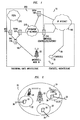
- a network 10 for wireless communications through which a user terminal 34 may roam, includes two types of base station, namely macrocell base stations and femtocell base stations (the latter being sometimes called “femtos").
- Each macrocell base station 22 has a radio coverage area 24 that is often referred to as a macrocell.
- the geographic extent of the macrocell 24 depends on the capabilities of the macrocell base station 22 and the surrounding geography.
- Each femtocell base station 30 is of a relatively low transmit power and hence each femtocell is of a small coverage area compared to a macrocell.
- a typical coverage range of a femtocell is tens of metres.
- Femtocell base stations have auto-configuring properties so as to support plug-and play deployment by users, for example in which femto base stations integrate themselves into an existing macrocell network so as to connect to the core network of the macrocell network. Femtocell base stations are sometimes referred to as femtos.
- the network 10 is managed by a radio network controller, RNC, 170.
- the radio network controller, RNC, 170 controls the operation, for example by communicating with macrocell base stations 22 via a backhaul communications link 160.
- the radio network controller 170 maintains a neighbour list which includes information about the geographical relationship between cells supported by base stations.
- the radio network controller 170 maintains location information which provides information on the location of the user equipment within the wireless communications system 10.
- the radio network controller 170 is operable to route traffic via circuit-switched and packet-switched networks. For circuit-switched traffic, a mobile switching centre 250 is provided with which the radio network controller 170 may communicate.
- the mobile switching centre 250 communicates with a circuit-switched network such as a public switched telephone network (PSTN) 210.
- a circuit-switched network such as a public switched telephone network (PSTN) 210.
- PSTN public switched telephone network
- the network controller 170 communicates with serving general packet radio service support nodes (SGSNs) 220 and a gateway general packet radio support node (GGSN) 180.
- SGSNs general packet radio service support nodes
- GGSN gateway general packet radio support node
- the GGSN then communicates with a packet-switch core 190 such as, for example, the Internet.
- the MSC 250, SGSN 220, GGSN 180 and operator IP network constitute a so-called core network 253.
- the SGSN 220 and GGSN 180 are connected by an operator IP network 215 to a femtocell controller/gateway 230.
- the femtocell controller/gateway 230 is connected via the Internet 190 to the femtocell base stations 30. These connections to the femtocell controller/gateway 230 are broadband Internet Protocol connections ("backhaul") 36.
- backhaul broadband Internet Protocol connections
- the femtocell base stations 30 are connected via the broadband Internet Protocol connections ("backhaul") 36 to the core network (not shown in Figure 2 ) and hence the rest of the telecommunications "world” (not shown in Figure 2 ).
- broadband Internet Protocol connection is a Digital Subscriber Line (DSL).
- the DSL connects a DSL transmitter-receiver ("transceiver") of the femtocell base station to the core network.
- the DSL allows voice calls and other services provided via the femtocell base station to be supported.
- the femtocell base station also includes a radio frequency (RF) transceiver connected to an antenna for radio communications.
- RF radio frequency
- An alternative to such a wired broadband backhaul is to have a wireless backhaul.
- the "backhaul" connections 36 allow communications between the femtocell base stations 30 through the core network (not shown).
- the macrocell base station is also connected to the core network (not shown in Figure 2 ).
- femtos 30 Some of the femtos 30 are femtos that are vehicle-controlling as explained below. In Figure 2 , one such femto 38 is shown. The femto 38 is referred to as a controlling-femto. A vehicle 11 is shown within the femtocell 32' of that controlling-femto 38.
- the controlling-femto 38 which in use is positioned near the roadside (not shown) includes a controller 40 connected via a transmitter-receiver stage 42 to an antenna 44.
- the controller is connected to a memory 46 that stores an identifier 48 that the femto is a controlling-femto 38.
- the identifier is a specific Closed Subscriber Group identity.
- This identifier is broadcast by the controlling-femto 38 as an indication to mobile user terminals of conventional type not to attach to the controlling-femto 38; in other words, not to handover an active session, or make an idle mode connection, with the controlling-femto 38.
- the identifier is also an indication to MTC units that have been previously configured to recognise the identifier, that the femto is a controlling-femto and so should be attached to. It can be considered that the MTC units are in a Closed Subscriber Group such that they may attach to any femto broadcasting that specific CSG identity, and only femtos that are controlling-femtos are permitted to broadcast that CSG identity.
- the controlling-femto 38 also includes a radar detector 46 configured to detect the speed and direction of movement of the vehicle 11.
- the controller 40 is connected to the radar detector 46 by a radar detector trigger unit 50 and a radar measurement receiver 52.
- the vehicle 11 includes an MTC unit 13 which can be connected by a radio communication path 15 to the controlling-femto 38.
- the MTC unit 13 is a wireless radio transmitter-receiver ("transceiver") that supports infrequent transmissions of relatively small amounts of data. MTC units are typically intended to be used in locations or positions that are fixed relatively speaking, for example mounted in a vehicle, and are intended to monitor the environment and send data in response to specific location-dependent triggers.
- the MTC unit 13 may be considered as a type of sensor that makes use of an existing wireless network to communicate with elements within that network.
- the MTC unit 13 is connected to an audiovisual warning generator 17 connected to a driver interface (not shown) comprising a display screen 19 and audio speaker 21.
- the MTC unit 13 is also connected to a brake controller 23 configured to control automatically applying the brakes (not shown) of the vehicle 11 upon command from the MTC unit 13.
- the controlling-femto 38 is deployed at the road side in this case at the end of a motorway exit slip-road 60 (also known in some countries as a ramp) so that MTC units in vehicles 11 passing that point will automatically attach to the controlling-femto 38.
- a motorway exit slip-road 60 also known in some countries as a ramp
- the controlling-femto 38 operates with low transmit power and hence limited range so that the femto 38 is only detectable to user terminals and MTC units that pass close by.
- the femto 38 makes repeated measurements over time using its co-located radar 46 to determine in which direction and at what speed the vehicle in which the MTC unit is deployed is travelling. Knowing the expected correct direction of traffic flow, on the one hand if it is determined that the vehicle is travelling in the correct direction then the femto 38 simply releases the radio connection with the MTC unit. On the other hand, if detemined that the vehicle is travelling in the wrong direction, a message is sent to the MTC unit 13 triggering the audiovisual warning generator 17 to provide a visual and/or audible warning to the driver of the vehicle 11 that he or she is travelling in the wrong direction.
- the MTC unit 13 in the vehicle 11 determines that the vehicle has not stopped a predetermined time after the warning has been issued, it commands the brake controller to automatically apply the brakes to prevent the vehicle being driven further along the road, thereby avoiding a dangerous situation.
- the MTC unit 13 in the vehicle 11 detects (step a) the femtocell 32', detects (step b) the identifier broadcast by the femto 38 and recognises (step c) the received identifier as that of a controlling-femto, and so attaches (steps d, d') to that controlling-femto.
- the attachment triggers (step e') the controlling-femto to use its radar to measure (step f) the speed and direction of the vehicle's travel, and so determine (step g') whether the car is going in the wrong directions down the slip road towards the motorway.
- step h' If yes (step h'), then the controlling-femto 38 sends a warning indication (step i') to the MTC unit 13 in the vehicle 11.
- step j the audiovisual warning generator 17 is triggered (step k) to send the automated audio and visual warnings to the driver.
- step l A check is then made (step l ) by the MTC unit as to whether the vehicle has stopped within a predetermined reasonable period of time. If No (step m) the brake controller 23 then acts to automatically apply the brakes (step n) so as to bring the vehicle to a halt.
- step g' If the determination (step g') of whether the car is going in the wrong directions down the slip road towards the motorway , is No, in other words the vehicle is travelling in the correct direction, then the radio connection between the controlling-femto 38 and MTC unit 13 is released by the controlling-femto 38 (step o').
- controlling-femto is controlled by a central control centre to send specific commands to a vehicle, such as a command instructing the vehicle to stop.
- the police issue a command via the central control centre for all controlling-femtos within the vicinity of the pursuit to broadcast a Closed Subscriber Group identity or other code recognisable by a MTC unit as indicating that the MTC unit within the vehicle should attach by radio to the controlling-femto.
- a command is sent to the vehicle which causes the vehicle to come to a halt.
- the radar of the controlling-femto is used to determine the current speed and direction of the vehicle and hence the optimal rate at which to apply the brakes so that the vehicle is halted safely. This information is conveyed in the command causing the vehicle to halt, thereby ending the pursuit.
- controlling-femto 38' including the radar 46' is connectable by radio to the vehicle 11'.
- the vehicle 11' includes an MTC unit 13' which can be connected by a radio communication path 15' to the controlling-femto 38'.
- the MTC unit 13' is connected to an audiovisual warning generator 17' connected to a driver interface (not shown) comprising a display screen 19' and audio speaker 21'.
- the MTC unit 13' is also connected to a brake controller 23' configured to control automatically applying the brakes (not shown) of the vehicle 11' upon command from the MTC unit 13'.
- a police vehicle 25 in pursuit of the vehicle 11' is connected by radio to a central control centre 27.
- the control centre 27 includes a decoder 29 of signals from the police vehicle 25 that identify the vehicle registration plate number of the vehicle being pursued, a database 31 relating vehicle registration plate number to an identifier of the corresponding MTC unit of the vehicle, an identifier 33 of which controlling-femto is connected to the identified MTC unit, and a command unit 35 configured to send a command to the controlling-femtos identified within the vicinity of the pursuit causing one of those controlling-femtos to cause the vehicle to be stopped.
- a command unit 35 configured to send a command to the controlling-femtos identified within the vicinity of the pursuit causing one of those controlling-femtos to cause the vehicle to be stopped.
- the decoder 29 of the control centre 27 receives (step A) an instruction from the police vehicle 25 to stop the vehicle 11' as they are in pursuit of that vehicle 11'.
- the instruction includes the registration plate number of the vehicle and geographic area of the police vehicle.
- the control centre uses its database 31 to determine (step B) the identity of the MTC unit 13' of the vehicle 11'.
- the control centre also identifies (Step C) which controlling-femtos are in the area of the police vehicle 25 and hence the vehicle 13' being pursued.
- the control centre then sends (step D) a message to all of the controlling-femtos in the area.
- the message includes the identity of the MTC unit 13' and an instruction to those controlling-femtos to broadcast the identifier that the femto is a controlling-femto configured to communicate with a Machine-Type-Communication (MTC) unit.
- MTC Machine-Type-Communication
- one of the controlling-femtos receives (step E) the message, has a MTC unit attach (step F), and upon checking (step G) whether the identity of the MTC unit as revealed by the attachment matches that of the vehicle identified in the message, determines (step H) that "Yes" there is a match.
- This causes that controlling-femto to trigger its radar to perform (step I) measurements on the vehicle as to its speed and direction, and gather (step J) the results of those measurements.
- the controlling femto then sends (step K) a stop command to the MTC unit 13' of the vehicle 11'. Conversely at step G, if there is not a match the radio attachment is released (step L).
- the MTC unit 13' detects a femto (step v), detects (step w) the identifier broadcast by the femto and determines (step x) from the received identifier whether the femto is a controlling-femto.If "yes" (step y), then the MTC unit attaches (step F') to that controlling-femto.
- step K' a stop command from the controlling-femto
- the MTC unit causes the brakes of the vehicle to be slowly, smoothly and safely applied (step z) thus bringing the vehicle to a halt and so terminating the pursuit.
- the controlling-femto upon a sought-for MTC unit attaching to a controlling-femto, the controlling-femto sends a message to the control centre indicating that that specific MTC unit has attached. In response, the control centre triggers a command specific to that femto to stop the vehicle.
- program storage devices e.g., digital data storage media, which are machine or computer readable and encode machine-executable or computer-executable programs of instructions, wherein said instructions perform some or all of the steps of said above-described methods.
- the program storage devices may be, e.g., digital memories, magnetic storage media such as a magnetic disks and magnetic tapes, hard drives, or optically readable digital data storage media.
- Some embodiments involve computers programmed to perform said steps of the above-described methods.
Abstract
Description
- The present invention relates to telecommunications, in particular to wireless telecommunications.
- A number of serious accidents and incidents are caused by vehicles being driven inappropriately; for example when driven in the wrong direction along roads, such as motorways and dual carriageways, or when driven dangerously during a police pursuit.
- Driving in the wrong direction, that is, against the correct direction of traffic, is often due to drivers failing to notice signs barring entry to that road from the direction in which the vehicle is travelling. This may be due to, for example, confusing signage, driver error, or poor visibility due to bad weather. In some scenarios, inappropriate and dangerous driving is a deliberate action, for example when the driver seeks to evade the police.
- Known solutions to the problem of a vehicle being driven in the wrong direction include the provision of warning road-signs that provide a visible instruction not to enter a particular road. However, these signs are often not seen or ignored, for example by a flustered or tired driver driving in the dark or when weather conditions are poor.
- For scenarios involving deliberately inappropriate driving, known solutions are for the police to deliberately attempt to halt the pursued vehicle, for example by puncturing its tyres or physically forcing the vehicle to stop. These solutions are often dangerous and error-prone.
- The reader is referred to the appended independent claims. Some preferred features are laid out in the dependent claims.
- An example of the present invention is a small cell base station for wireless telecommunications. The base station is configured to broadcast an identifier that the base station is configured to be able to communicate with any one of multiple Machine-Type-Communication (MTC) units, to receive from a MTC unit a reply indicating the MTC unit is currently in the radio coverage area of the small cell base station, and to send an indication to the MTC unit to cease movement.
- Some embodiments provide an automated approach to detecting when vehicles are being driven inappropriately and to prevent them being driven further. Some embodiments involve using a femtocell as a controlling wireless network for which an MTC unit on the vehicle is a client.
- Some embodiments involve MTC units deployed within vehicles together with femtocells deployed at key road locations in order to use automated indications to prevent vehicular incidents. Vehicles may be prevented from being driven inappropriately, without relying solely on road signs to indicate that a road should not be entered. Furthermore, deliberate attempts to travel in the wrong direction along a road may be prevented, for example during a police chase.
- Some embodiments prevent incidents when vehicles are driven dangerously, for example in the wrong direction, and so aid road safety. Such incidents are often serious, resulting in injury or loss of life.
- Embodiments of the present invention will now be described by way of example and with reference to the drawings, in which:
-
Figure 1 is a diagram illustrating a wireless communications network according to a first embodiment of the present invention, -
Figure 2 is a diagram illustrating an example femtocell base station deployment within one macrocell shown inFigure 1 , -
Figure 3 is a diagram illustrating in more detail a femtocell base station and vehicle shown inFigure 2 , -
Figure 4 is a diagram illustrating an example scenario in which the femtocell base station and vehicle shown inFigure 3 communicate, -
Figure 5 is a flow diagram illustrating the operation of the femtocell base station in the scenario shown inFigure 4 , -
Figure 6 is a flow diagram illustrating the operation of the vehicle in the scenario shown inFigure 4 , -
Figure 7 is a diagram illustrating a femtocell base station, a central controller, a vehicle, and police car, according to a second embodiment of the present invention in which the central controller communicates with the femtocell base station and the femtocell base station communicates with the vehicle, -
Figure 8 is a flow diagram illustrating the operation of the central controller in the scenario shown inFigure 7 , -
Figure 9 is a flow diagram illustrating the operation of the femtocell base station in the scenario shown inFigure 7 , and -
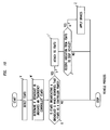
Figure 10 is a flow diagram illustrating the operation of the vehicle in the scenario shown inFigure 7 . - The inventors realised that it would be beneficial to detect scenarios where a vehicle is going in the wrong direction, that is against the correct direction of the road and provide a way to help halt that inappropriate vehicle movement. The inventors realised that a wireless network element could be used to monitor and provide information to the vehicle to warn the vehicle that the vehicle is travelling in the wrong direction or to enable the vehicle to be stopped.
- The inventors realised that a Machine-Type-Communication (MTC) unit installed in a vehicle can provide a link to roadside wireless network elements, such as femtocell base stations and the communications links can be configured to send information or commands to the MTC unit to trigger specific actions within the vehicle.
- We now describe a network including femtocell base stations then look in greater detail at a vehicle-controlling femtocell base station and a vehicle including a Machine-Type-Communication (MTC) unit, and then how they interact.
- As shown in
Figures 1 and 2 , anetwork 10 for wireless communications, through which auser terminal 34 may roam, includes two types of base station, namely macrocell base stations and femtocell base stations (the latter being sometimes called "femtos"). - One
macrocell base station 22 is shown inFigures 1 and 2 for simplicity. Each macrocell base station has aradio coverage area 24 that is often referred to as a macrocell. The geographic extent of themacrocell 24 depends on the capabilities of themacrocell base station 22 and the surrounding geography. - Each
femtocell base station 30 is of a relatively low transmit power and hence each femtocell is of a small coverage area compared to a macrocell. A typical coverage range of a femtocell is tens of metres. - Femtocell base stations have auto-configuring properties so as to support plug-and play deployment by users, for example in which femto base stations integrate themselves into an existing macrocell network so as to connect to the core network of the macrocell network. Femtocell base stations are sometimes referred to as femtos.
- As shown in
Figure 1 , thenetwork 10 is managed by a radio network controller, RNC, 170. The radio network controller, RNC, 170 controls the operation, for example by communicating withmacrocell base stations 22 via abackhaul communications link 160. Theradio network controller 170 maintains a neighbour list which includes information about the geographical relationship between cells supported by base stations. In addition, theradio network controller 170 maintains location information which provides information on the location of the user equipment within thewireless communications system 10. Theradio network controller 170 is operable to route traffic via circuit-switched and packet-switched networks. For circuit-switched traffic, amobile switching centre 250 is provided with which theradio network controller 170 may communicate. Themobile switching centre 250 communicates with a circuit-switched network such as a public switched telephone network (PSTN) 210. For packet-switched traffic, thenetwork controller 170 communicates with serving general packet radio service support nodes (SGSNs) 220 and a gateway general packet radio support node (GGSN) 180. The GGSN then communicates with a packet-switch core 190 such as, for example, the Internet. - The MSC 250, SGSN 220, GGSN 180 and operator IP network constitute a so-called
core network 253. The SGSN 220 and GGSN 180 are connected by anoperator IP network 215 to a femtocell controller/gateway 230. - The femtocell controller/gateway 230 is connected via the Internet 190 to the femtocell
base stations 30. These connections to the femtocell controller/gateway 230 are broadband Internet Protocol connections ("backhaul") 36. - In
Figure 2 , threefemtocell base stations 30 andcorresponding femtocells 32 are shown for simplicity. - As shown in
Figure 2 , thefemtocell base stations 30 are connected via the broadband Internet Protocol connections ("backhaul") 36 to the core network (not shown inFigure 2 ) and hence the rest of the telecommunications "world" (not shown inFigure 2 ). One type of broadband Internet Protocol connection is a Digital Subscriber Line (DSL). The DSL connects a DSL transmitter-receiver ("transceiver") of the femtocell base station to the core network. The DSL allows voice calls and other services provided via the femtocell base station to be supported. The femtocell base station also includes a radio frequency (RF) transceiver connected to an antenna for radio communications. An alternative to such a wired broadband backhaul is to have a wireless backhaul. - The "backhaul"
connections 36 allow communications between thefemtocell base stations 30 through the core network (not shown). The macrocell base station is also connected to the core network (not shown inFigure 2 ). - Some of the
femtos 30 are femtos that are vehicle-controlling as explained below. InFigure 2 , onesuch femto 38 is shown. Thefemto 38 is referred to as a controlling-femto. Avehicle 11 is shown within the femtocell 32' of that controlling-femto 38. - As shown in
Figure 3 , the controlling-femto 38 which in use is positioned near the roadside (not shown) includes acontroller 40 connected via a transmitter-receiver stage 42 to anantenna 44. The controller is connected to amemory 46 that stores an identifier 48 that the femto is a controlling-femto 38. In this example the identifier is a specific Closed Subscriber Group identity. - This identifier is broadcast by the controlling-
femto 38 as an indication to mobile user terminals of conventional type not to attach to the controlling-femto 38; in other words, not to handover an active session, or make an idle mode connection, with the controlling-femto 38. The identifier is also an indication to MTC units that have been previously configured to recognise the identifier, that the femto is a controlling-femto and so should be attached to. It can be considered that the MTC units are in a Closed Subscriber Group such that they may attach to any femto broadcasting that specific CSG identity, and only femtos that are controlling-femtos are permitted to broadcast that CSG identity. - The controlling-
femto 38 also includes aradar detector 46 configured to detect the speed and direction of movement of thevehicle 11. Thecontroller 40 is connected to theradar detector 46 by a radardetector trigger unit 50 and aradar measurement receiver 52. - As also shown in
Figure 3 , thevehicle 11 includes anMTC unit 13 which can be connected by aradio communication path 15 to the controlling-femto 38. - The
MTC unit 13 is a wireless radio transmitter-receiver ("transceiver") that supports infrequent transmissions of relatively small amounts of data. MTC units are typically intended to be used in locations or positions that are fixed relatively speaking, for example mounted in a vehicle, and are intended to monitor the environment and send data in response to specific location-dependent triggers. TheMTC unit 13 may be considered as a type of sensor that makes use of an existing wireless network to communicate with elements within that network. - As shown in
Figure 3 , in thevehicle 11, theMTC unit 13 is connected to anaudiovisual warning generator 17 connected to a driver interface (not shown) comprising adisplay screen 19 andaudio speaker 21. TheMTC unit 13 is also connected to abrake controller 23 configured to control automatically applying the brakes (not shown) of thevehicle 11 upon command from theMTC unit 13. - As shown in
Figure 4 , the controlling-femto 38 is deployed at the road side in this case at the end of a motorway exit slip-road 60 (also known in some countries as a ramp) so that MTC units invehicles 11 passing that point will automatically attach to the controlling-femto 38. - The controlling-
femto 38 operates with low transmit power and hence limited range so that thefemto 38 is only detectable to user terminals and MTC units that pass close by. - Basically speaking, once the
MTC unit 13 attaches, thefemto 38 makes repeated measurements over time using itsco-located radar 46 to determine in which direction and at what speed the vehicle in which the MTC unit is deployed is travelling. Knowing the expected correct direction of traffic flow, on the one hand if it is determined that the vehicle is travelling in the correct direction then thefemto 38 simply releases the radio connection with the MTC unit. On the other hand, if detemined that the vehicle is travelling in the wrong direction, a message is sent to theMTC unit 13 triggering theaudiovisual warning generator 17 to provide a visual and/or audible warning to the driver of thevehicle 11 that he or she is travelling in the wrong direction. - Subsequently if the
MTC unit 13 in thevehicle 11 determines that the vehicle has not stopped a predetermined time after the warning has been issued, it commands the brake controller to automatically apply the brakes to prevent the vehicle being driven further along the road, thereby avoiding a dangerous situation. - The above described operation is now described again in more detail with reference to
Figures 5 and6 . - As shown in
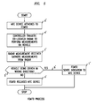
Figures 5 and6 , upon the vehicle approaching the slip road, theMTC unit 13 in thevehicle 11 detects (step a) the femtocell 32', detects (step b) the identifier broadcast by thefemto 38 and recognises (step c) the received identifier as that of a controlling-femto, and so attaches (steps d, d') to that controlling-femto. - Once attached the attachment triggers (step e') the controlling-femto to use its radar to measure (step f) the speed and direction of the vehicle's travel, and so determine (step g') whether the car is going in the wrong directions down the slip road towards the motorway.
- If yes (step h'), then the controlling-
femto 38 sends a warning indication (step i') to theMTC unit 13 in thevehicle 11. - In the
vehicle 11, upon the warning indication being received (step j), theaudiovisual warning generator 17 is triggered (step k) to send the automated audio and visual warnings to the driver. A check is then made (step l) by the MTC unit as to whether the vehicle has stopped within a predetermined reasonable period of time. If No (step m) thebrake controller 23 then acts to automatically apply the brakes (step n) so as to bring the vehicle to a halt. - If the determination (step g') of whether the car is going in the wrong directions down the slip road towards the motorway , is No, in other words the vehicle is travelling in the correct direction, then the radio connection between the controlling-
femto 38 andMTC unit 13 is released by the controlling-femto 38 (step o'). - In a further example the controlling-femto is controlled by a central control centre to send specific commands to a vehicle, such as a command instructing the vehicle to stop.
- For example in the event of a police pursuit of a vehicle , the police issue a command via the central control centre for all controlling-femtos within the vicinity of the pursuit to broadcast a Closed Subscriber Group identity or other code recognisable by a MTC unit as indicating that the MTC unit within the vehicle should attach by radio to the controlling-femto.
- Once the MTC unit attaches to the controlling-femto, a command is sent to the vehicle which causes the vehicle to come to a halt. The radar of the controlling-femto is used to determine the current speed and direction of the vehicle and hence the optimal rate at which to apply the brakes so that the vehicle is halted safely. This information is conveyed in the command causing the vehicle to halt, thereby ending the pursuit.
- In this example, as shown in
Figure 7 , the controlling-femto 38' including the radar 46' is connectable by radio to the vehicle 11'. - As shown in
Figure 7 , the vehicle 11' includes an MTC unit 13' which can be connected by a radio communication path 15' to the controlling-femto 38'. The MTC unit 13' is connected to an audiovisual warning generator 17' connected to a driver interface (not shown) comprising a display screen 19' and audio speaker 21'. The MTC unit 13' is also connected to a brake controller 23' configured to control automatically applying the brakes (not shown) of the vehicle 11' upon command from the MTC unit 13'. - As shown in
Figure 7 , apolice vehicle 25 in pursuit of the vehicle 11' is connected by radio to acentral control centre 27. Thecontrol centre 27 includes adecoder 29 of signals from thepolice vehicle 25 that identify the vehicle registration plate number of the vehicle being pursued, adatabase 31 relating vehicle registration plate number to an identifier of the corresponding MTC unit of the vehicle, anidentifier 33 of which controlling-femto is connected to the identified MTC unit, and acommand unit 35 configured to send a command to the controlling-femtos identified within the vicinity of the pursuit causing one of those controlling-femtos to cause the vehicle to be stopped. This is explained in more detail below with reference toFigures 8 ,9 and10 . - As shown in
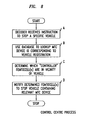
Figure 8 , thedecoder 29 of thecontrol centre 27 receives (step A) an instruction from thepolice vehicle 25 to stop the vehicle 11' as they are in pursuit of that vehicle 11'. The instruction includes the registration plate number of the vehicle and geographic area of the police vehicle. - The control centre uses its
database 31 to determine (step B) the identity of the MTC unit 13' of the vehicle 11'. The control centre also identifies (Step C) which controlling-femtos are in the area of thepolice vehicle 25 and hence the vehicle 13' being pursued. The control centre then sends (step D) a message to all of the controlling-femtos in the area. The message includes the identity of the MTC unit 13' and an instruction to those controlling-femtos to broadcast the identifier that the femto is a controlling-femto configured to communicate with a Machine-Type-Communication (MTC) unit. - As shown in
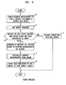
Figure 9 , one of the controlling-femtos receives (step E) the message, has a MTC unit attach (step F), and upon checking (step G) whether the identity of the MTC unit as revealed by the attachment matches that of the vehicle identified in the message, determines (step H) that "Yes" there is a match. This causes that controlling-femto to trigger its radar to perform (step I) measurements on the vehicle as to its speed and direction, and gather (step J) the results of those measurements. The controlling femto then sends (step K) a stop command to the MTC unit 13' of the vehicle 11'. Conversely at step G, if there is not a match the radio attachment is released (step L). - As shown in
Figure 10 , from the perspective of the MTC unit 13', the MTC unit 13' detects a femto (step v), detects (step w) the identifier broadcast by the femto and determines (step x) from the received identifier whether the femto is a controlling-femto.If "yes" (step y), then the MTC unit attaches (step F') to that controlling-femto. Upon receiving (step K') a stop command from the controlling-femto, the MTC unit causes the brakes of the vehicle to be slowly, smoothly and safely applied (step z) thus bringing the vehicle to a halt and so terminating the pursuit. - In a basically similar approach to that described with reference to
Figures 7 to 10 , upon a sought-for MTC unit attaching to a controlling-femto, the controlling-femto sends a message to the control centre indicating that that specific MTC unit has attached. In response, the control centre triggers a command specific to that femto to stop the vehicle. - Although the specific examples detailed above involve the use of radar, other types of detectors of direction, or direction and speed, could be used instead, for example Doppler detectors.
- The present invention may be embodied in other specific forms without departing from its essential characteristics. The described embodiments are to be considered in all respects only as illustrative and not restrictive. The scope of the invention is, therefore, indicated by the appended claims rather than by the foregoing description. All changes that come within the meaning and range of equivalency of the claims are to be embraced within their scope.
- A person skilled in the art would readily recognize that steps of various above-described methods can be performed by programmed computers. Some embodiments relate to program storage devices, e.g., digital data storage media, which are machine or computer readable and encode machine-executable or computer-executable programs of instructions, wherein said instructions perform some or all of the steps of said above-described methods. The program storage devices may be, e.g., digital memories, magnetic storage media such as a magnetic disks and magnetic tapes, hard drives, or optically readable digital data storage media. Some embodiments involve computers programmed to perform said steps of the above-described methods.
Claims (13)
- A small cell base station for wireless telecommunications, the base station being configured to:broadcast an identifier that the base station is configured to be able to communicate with any one of multiple Machine-Type-Communication (MTC) units;receive from a MTC unit a reply indicating the MTC unit is currently in the radio coverage area of the small cell base station; andsend an indication to the MTC unit to cease movement.
- A small cell base station according to claim 1, including a radar detector configured to measure direction of movement of the MTC unit; the small cell base station being configured to determine whether the MTC unit is travelling in a forbidden direction, and upon determining that the MTC unit is travelling in a forbidden direction, to send the indication to cease movement.
- A small cell base station according to claim 1 or claim 2, including a radar detector configured to determine speed of the MTC unit, and upon determining that the MTC unit is moving, sending the indication to the MTC unit to cease movement.
- A vehicle in which a MTC unit is mounted, the MTC unit being configured to receive from a small cell base station an indication to the MTC unit to cease movement and to respond by triggering the vehicle to stop.
- A vehicle according to claim 4, in which the MTC unit triggers an audiovisual instruction to the driver of the vehicle to stop the vehicle.
- A vehicle according to claim 4 or claim 5, in which the MTC unit triggers the vehicle to automatically apply its brake so as to cause the vehicle to stop.
- A braking system for a vehicle, the system comprising an MTC unit, a brake controller, and a brake, the MTC unit being configured to receive from a small cell base station an indication to the MTC unit to cease movement and to respond by sending a command to the brake controller, the brake controller being configured to respond to the command by sending a control signal towards the brake to automatically apply the brake.
- A telecommunications network comprising a plurality of small cell base stations according to claim 1, a control node configured to receive an identity of a vehicle to be stopped, to look up a corresponding Machine-Type_Communication (MTC) unit identity, and to send a stop notification to a set of the plurality of small cell base stations causing them to broadcast said indication to said Machine-Type-Communication (MTC) unit to cease movement in response to the MTC unit having said identity attaching to one of the plurality of base stations.
- A telecommunications network according to claim 8, in which the set of small cell base stations is selected dependent on knowledge of an area in which the MTC unit having said identity may be, and knowledge of where the small cell base stations are situated.
- A method of controlling movement of a Machine-Type-Communication (MTC) unit from a small cell base station, the method comprising:broadcasting an identifier that the base station is configured to be able to communicate with any one of multiple MTC units;receiving a reply from a MTC unit indicating the MTC unit is currently in the radio coverage area of the small cell base station, andsending an indication towards the MTC unit to cease movement.
- A method according to claim 10, in a system comprising the MTC unit, a brake controller, and a brake,
the MTC unit receiving the indication to cease movement and responding by sending a command to a brake controller,
the brake controller responding to the command by sending a control signal towards a brake to automatically apply the brake. - A method according to claim 10 or 11, further comprising:measuring direction of movement of the MTC unit;determining whether the MTC unit is travelling in a forbidden direction, and upon determining that the MTC unit is travelling in a forbidden direction, sending the indication to cease movement.
- A method according to any of claims 10 to 12, in which the MTC unit is mounted in a vehicle, the MTC unit receiving from the small cell base station an indication to the MTC unit to cease movement and responding by triggering the vehicle to stop.
Priority Applications (1)
| Application Number | Priority Date | Filing Date | Title |
|---|---|---|---|
| EP20110290217 EP2521110B1 (en) | 2011-05-06 | 2011-05-06 | A small cell base station, a method of controlling movement of a machine-type-communication (MTC) unit, and a braking system for a vehicle |
Applications Claiming Priority (1)
| Application Number | Priority Date | Filing Date | Title |
|---|---|---|---|
| EP20110290217 EP2521110B1 (en) | 2011-05-06 | 2011-05-06 | A small cell base station, a method of controlling movement of a machine-type-communication (MTC) unit, and a braking system for a vehicle |
Publications (2)
| Publication Number | Publication Date |
|---|---|
| EP2521110A1 true EP2521110A1 (en) | 2012-11-07 |
| EP2521110B1 EP2521110B1 (en) | 2013-11-13 |
Family
ID=44543111
Family Applications (1)
| Application Number | Title | Priority Date | Filing Date |
|---|---|---|---|
| EP20110290217 Active EP2521110B1 (en) | 2011-05-06 | 2011-05-06 | A small cell base station, a method of controlling movement of a machine-type-communication (MTC) unit, and a braking system for a vehicle |
Country Status (1)
| Country | Link |
|---|---|
| EP (1) | EP2521110B1 (en) |
Cited By (4)
| Publication number | Priority date | Publication date | Assignee | Title |
|---|---|---|---|---|
| CN105894802A (en) * | 2015-04-10 | 2016-08-24 | 杭州远眺科技有限公司 | GPS data-based traffic congestion propagation path calculating method |
| CN106899428A (en) * | 2016-09-27 | 2017-06-27 | 兰州交通大学 | A kind of machine type communication traffic forecast category of model method under Railway Environment |
| EP3188153A1 (en) * | 2015-12-29 | 2017-07-05 | Thunder Power New Energy Vehicle Development Company Limited | Vehicle hazard detection and warning system |
| US10081343B2 (en) | 2015-12-29 | 2018-09-25 | Thunder Power New Energy Vehicle Development Company Limited | [Monitor] vehicle hazard detection and warning system |
Citations (3)
| Publication number | Priority date | Publication date | Assignee | Title |
|---|---|---|---|---|
| EP1939833A1 (en) * | 2006-12-28 | 2008-07-02 | Vodafone Group PLC | Method for improving traffic safety by means of using beacons |
| DE102007027651A1 (en) * | 2007-06-15 | 2008-12-18 | Continental Automotive Gmbh | Method for operating safety system of motor vehicle, involves producing warning signal for driver of vehicle, if vehicle is not drove in correct direction, and is automatically engaged into driving system of vehicle |
| EP2249603A1 (en) * | 2009-05-07 | 2010-11-10 | Alcatel Lucent | Obtaining information of a neighbouring base station |
-
2011
- 2011-05-06 EP EP20110290217 patent/EP2521110B1/en active Active
Patent Citations (3)
| Publication number | Priority date | Publication date | Assignee | Title |
|---|---|---|---|---|
| EP1939833A1 (en) * | 2006-12-28 | 2008-07-02 | Vodafone Group PLC | Method for improving traffic safety by means of using beacons |
| DE102007027651A1 (en) * | 2007-06-15 | 2008-12-18 | Continental Automotive Gmbh | Method for operating safety system of motor vehicle, involves producing warning signal for driver of vehicle, if vehicle is not drove in correct direction, and is automatically engaged into driving system of vehicle |
| EP2249603A1 (en) * | 2009-05-07 | 2010-11-10 | Alcatel Lucent | Obtaining information of a neighbouring base station |
Cited By (6)
| Publication number | Priority date | Publication date | Assignee | Title |
|---|---|---|---|---|
| CN105894802A (en) * | 2015-04-10 | 2016-08-24 | 杭州远眺科技有限公司 | GPS data-based traffic congestion propagation path calculating method |
| EP3188153A1 (en) * | 2015-12-29 | 2017-07-05 | Thunder Power New Energy Vehicle Development Company Limited | Vehicle hazard detection and warning system |
| US10081343B2 (en) | 2015-12-29 | 2018-09-25 | Thunder Power New Energy Vehicle Development Company Limited | [Monitor] vehicle hazard detection and warning system |
| US10246065B2 (en) | 2015-12-29 | 2019-04-02 | Thunder Power New Energy Vehicle Development Company Limited | Vehicle hazard detection and warning system |
| CN106899428A (en) * | 2016-09-27 | 2017-06-27 | 兰州交通大学 | A kind of machine type communication traffic forecast category of model method under Railway Environment |
| CN106899428B (en) * | 2016-09-27 | 2020-06-30 | 兰州交通大学 | Machine type communication service prediction model classification method in railway environment |
Also Published As
| Publication number | Publication date |
|---|---|
| EP2521110B1 (en) | 2013-11-13 |
Similar Documents
| Publication | Publication Date | Title |
|---|---|---|
| EP2044729B1 (en) | Emergency call system using specific mobile user information | |
| US9374665B2 (en) | Location option control for minimization of drive test in LTE systems | |
| CA2882295C (en) | Dynamically re-configured incident scene communication | |
| CN102682594B (en) | Method and system for monitoring pedestrian violation based on mobile communication | |
| JP6344239B2 (en) | Traffic information distribution system, cellular communication system, and communication terminal | |
| EP2009941A1 (en) | A method of adjusting the position of a picocell base station, as well as apparatus therefor | |
| BRPI0622043B1 (en) | METHOD AND AUTOMATIC ELECTRONIC AUTHORIZATION SYSTEM FOR ENTRY INTO A GEOGRAPHICAL AREA BASED ON DETECTION OF A MOBILE STATION OPERATING IN A GLOBAL COMMUNICATION NETWORK SYSTEM, AND, MANUFACTURING ARTICLE | |
| EP2521110B1 (en) | A small cell base station, a method of controlling movement of a machine-type-communication (MTC) unit, and a braking system for a vehicle | |
| US6641091B1 (en) | Highway railroad crossing vehicle detection methods and systems | |
| CN106559442A (en) | The synchronous method of board units position, device and equipment in car networking | |
| WO2015001795A1 (en) | Delivery device, communication terminal, delivery method, reception method, and program-containing non-transitory computer-readable medium | |
| EP3510812B1 (en) | System and method for restricting access to a mobile communications network | |
| US11626022B2 (en) | Method, device, and system for detecting a dangerous road event and/or condition | |
| JP6292222B2 (en) | Communication system and distribution information determination device | |
| EP1939833A1 (en) | Method for improving traffic safety by means of using beacons | |
| Zhou et al. | Process for evaluating the data transfer performance of wireless traffic sensors for real‐time intelligent transportation systems applications | |
| EP1868164B1 (en) | Method for recording chargeable motor vehicles on toll roads and provision of information on the motor vehicles recorded | |
| US20150024795A1 (en) | Femtocell base station, a user terminal, a method of sending femtocell base station status information to a user terminal, and a method of receiving | |
| EP3001706A1 (en) | A small cell base station, a vehicle braking circuit, and method of using a small cell base station near a crossing | |
| EP2367161A1 (en) | A sensor, and a method of a sensor detecting a user terminal that is in idle mode connected to a base station | |
| KR100738418B1 (en) | Method and server for notifying the traffic alarm using a mobile phone location information | |
| US20080303649A1 (en) | Method for improving traffic safety by means of using beacons | |
| US8805422B2 (en) | Network device to monitor radio base station and a method thereof | |
| WO2022190303A1 (en) | Information processing device, information processing method, information processing system, and computer-readable medium | |
| WO2022190302A1 (en) | Information processing device, information processing method, information processing system, and computer-readable medium |
Legal Events
| Date | Code | Title | Description |
|---|---|---|---|
| PUAI | Public reference made under article 153(3) epc to a published international application that has entered the european phase |
Free format text: ORIGINAL CODE: 0009012 |
|
| AK | Designated contracting states |
Kind code of ref document: A1 Designated state(s): AL AT BE BG CH CY CZ DE DK EE ES FI FR GB GR HR HU IE IS IT LI LT LU LV MC MK MT NL NO PL PT RO RS SE SI SK SM TR |
|
| AX | Request for extension of the european patent |
Extension state: BA ME |
|
| 17P | Request for examination filed |
Effective date: 20130507 |
|
| GRAP | Despatch of communication of intention to grant a patent |
Free format text: ORIGINAL CODE: EPIDOSNIGR1 |
|
| RIC1 | Information provided on ipc code assigned before grant |
Ipc: H04W 64/00 20090101ALI20130628BHEP Ipc: B60T 7/18 20060101ALI20130628BHEP Ipc: G08G 1/0967 20060101AFI20130628BHEP |
|
| INTG | Intention to grant announced |
Effective date: 20130726 |
|
| GRAS | Grant fee paid |
Free format text: ORIGINAL CODE: EPIDOSNIGR3 |
|
| 111Z | Information provided on other rights and legal means of execution |
Free format text: AL AT BE BG CH CY CZ DE DK EE ES FI FR GB GR HR HU IE IS IT LI LT LU LV MC MK MT NL NO PL PT RO RS SE SI SK SM TR Effective date: 20130410 |
|
| GRAA | (expected) grant |
Free format text: ORIGINAL CODE: 0009210 |
|
| AK | Designated contracting states |
Kind code of ref document: B1 Designated state(s): AL AT BE BG CH CY CZ DE DK EE ES FI FR GB GR HR HU IE IS IT LI LT LU LV MC MK MT NL NO PL PT RO RS SE SI SK SM TR |
|
| REG | Reference to a national code |
Ref country code: GB Ref legal event code: FG4D |
|
| REG | Reference to a national code |
Ref country code: CH Ref legal event code: EP |
|
| REG | Reference to a national code |
Ref country code: AT Ref legal event code: REF Ref document number: 640857 Country of ref document: AT Kind code of ref document: T Effective date: 20131215 |
|
| REG | Reference to a national code |
Ref country code: IE Ref legal event code: FG4D |
|
| REG | Reference to a national code |
Ref country code: DE Ref legal event code: R096 Ref document number: 602011003709 Country of ref document: DE Effective date: 20140109 |
|
| REG | Reference to a national code |
Ref country code: NL Ref legal event code: VDEP Effective date: 20131113 |
|
| REG | Reference to a national code |
Ref country code: AT Ref legal event code: MK05 Ref document number: 640857 Country of ref document: AT Kind code of ref document: T Effective date: 20131113 |
|
| REG | Reference to a national code |
Ref country code: LT Ref legal event code: MG4D |
|
| PG25 | Lapsed in a contracting state [announced via postgrant information from national office to epo] |
Ref country code: LT Free format text: LAPSE BECAUSE OF FAILURE TO SUBMIT A TRANSLATION OF THE DESCRIPTION OR TO PAY THE FEE WITHIN THE PRESCRIBED TIME-LIMIT Effective date: 20131113 Ref country code: NL Free format text: LAPSE BECAUSE OF FAILURE TO SUBMIT A TRANSLATION OF THE DESCRIPTION OR TO PAY THE FEE WITHIN THE PRESCRIBED TIME-LIMIT Effective date: 20131113 Ref country code: HR Free format text: LAPSE BECAUSE OF FAILURE TO SUBMIT A TRANSLATION OF THE DESCRIPTION OR TO PAY THE FEE WITHIN THE PRESCRIBED TIME-LIMIT Effective date: 20131113 Ref country code: FI Free format text: LAPSE BECAUSE OF FAILURE TO SUBMIT A TRANSLATION OF THE DESCRIPTION OR TO PAY THE FEE WITHIN THE PRESCRIBED TIME-LIMIT Effective date: 20131113 Ref country code: NO Free format text: LAPSE BECAUSE OF FAILURE TO SUBMIT A TRANSLATION OF THE DESCRIPTION OR TO PAY THE FEE WITHIN THE PRESCRIBED TIME-LIMIT Effective date: 20140213 Ref country code: SE Free format text: LAPSE BECAUSE OF FAILURE TO SUBMIT A TRANSLATION OF THE DESCRIPTION OR TO PAY THE FEE WITHIN THE PRESCRIBED TIME-LIMIT Effective date: 20131113 Ref country code: IS Free format text: LAPSE BECAUSE OF FAILURE TO SUBMIT A TRANSLATION OF THE DESCRIPTION OR TO PAY THE FEE WITHIN THE PRESCRIBED TIME-LIMIT Effective date: 20140313 |
|
| PG25 | Lapsed in a contracting state [announced via postgrant information from national office to epo] |
Ref country code: BE Free format text: LAPSE BECAUSE OF FAILURE TO SUBMIT A TRANSLATION OF THE DESCRIPTION OR TO PAY THE FEE WITHIN THE PRESCRIBED TIME-LIMIT Effective date: 20131113 Ref country code: RS Free format text: LAPSE BECAUSE OF FAILURE TO SUBMIT A TRANSLATION OF THE DESCRIPTION OR TO PAY THE FEE WITHIN THE PRESCRIBED TIME-LIMIT Effective date: 20131113 Ref country code: CY Free format text: LAPSE BECAUSE OF FAILURE TO SUBMIT A TRANSLATION OF THE DESCRIPTION OR TO PAY THE FEE WITHIN THE PRESCRIBED TIME-LIMIT Effective date: 20131113 Ref country code: AT Free format text: LAPSE BECAUSE OF FAILURE TO SUBMIT A TRANSLATION OF THE DESCRIPTION OR TO PAY THE FEE WITHIN THE PRESCRIBED TIME-LIMIT Effective date: 20131113 Ref country code: LV Free format text: LAPSE BECAUSE OF FAILURE TO SUBMIT A TRANSLATION OF THE DESCRIPTION OR TO PAY THE FEE WITHIN THE PRESCRIBED TIME-LIMIT Effective date: 20131113 Ref country code: ES Free format text: LAPSE BECAUSE OF FAILURE TO SUBMIT A TRANSLATION OF THE DESCRIPTION OR TO PAY THE FEE WITHIN THE PRESCRIBED TIME-LIMIT Effective date: 20131113 |
|
| PG25 | Lapsed in a contracting state [announced via postgrant information from national office to epo] |
Ref country code: PT Free format text: LAPSE BECAUSE OF FAILURE TO SUBMIT A TRANSLATION OF THE DESCRIPTION OR TO PAY THE FEE WITHIN THE PRESCRIBED TIME-LIMIT Effective date: 20140313 |
|
| PG25 | Lapsed in a contracting state [announced via postgrant information from national office to epo] |
Ref country code: EE Free format text: LAPSE BECAUSE OF FAILURE TO SUBMIT A TRANSLATION OF THE DESCRIPTION OR TO PAY THE FEE WITHIN THE PRESCRIBED TIME-LIMIT Effective date: 20131113 |
|
| REG | Reference to a national code |
Ref country code: CH Ref legal event code: PCOW Free format text: NEW ADDRESS: 148/152 ROUTE DE LA REINE, 92100 BOULOGNE-BILLANCOURT (FR) |
|
| REG | Reference to a national code |
Ref country code: DE Ref legal event code: R097 Ref document number: 602011003709 Country of ref document: DE |
|
| RAP2 | Party data changed (patent owner data changed or rights of a patent transferred) |
Owner name: ALCATEL LUCENT |
|
| PG25 | Lapsed in a contracting state [announced via postgrant information from national office to epo] |
Ref country code: PL Free format text: LAPSE BECAUSE OF FAILURE TO SUBMIT A TRANSLATION OF THE DESCRIPTION OR TO PAY THE FEE WITHIN THE PRESCRIBED TIME-LIMIT Effective date: 20131113 Ref country code: RO Free format text: LAPSE BECAUSE OF FAILURE TO SUBMIT A TRANSLATION OF THE DESCRIPTION OR TO PAY THE FEE WITHIN THE PRESCRIBED TIME-LIMIT Effective date: 20131113 Ref country code: SK Free format text: LAPSE BECAUSE OF FAILURE TO SUBMIT A TRANSLATION OF THE DESCRIPTION OR TO PAY THE FEE WITHIN THE PRESCRIBED TIME-LIMIT Effective date: 20131113 Ref country code: CZ Free format text: LAPSE BECAUSE OF FAILURE TO SUBMIT A TRANSLATION OF THE DESCRIPTION OR TO PAY THE FEE WITHIN THE PRESCRIBED TIME-LIMIT Effective date: 20131113 |
|
| PLBE | No opposition filed within time limit |
Free format text: ORIGINAL CODE: 0009261 |
|
| STAA | Information on the status of an ep patent application or granted ep patent |
Free format text: STATUS: NO OPPOSITION FILED WITHIN TIME LIMIT |
|
| PG25 | Lapsed in a contracting state [announced via postgrant information from national office to epo] |
Ref country code: DK Free format text: LAPSE BECAUSE OF FAILURE TO SUBMIT A TRANSLATION OF THE DESCRIPTION OR TO PAY THE FEE WITHIN THE PRESCRIBED TIME-LIMIT Effective date: 20131113 |
|
| 26N | No opposition filed |
Effective date: 20140814 |
|
| REG | Reference to a national code |
Ref country code: DE Ref legal event code: R097 Ref document number: 602011003709 Country of ref document: DE Effective date: 20140814 |
|
| PG25 | Lapsed in a contracting state [announced via postgrant information from national office to epo] |
Ref country code: LU Free format text: LAPSE BECAUSE OF FAILURE TO SUBMIT A TRANSLATION OF THE DESCRIPTION OR TO PAY THE FEE WITHIN THE PRESCRIBED TIME-LIMIT Effective date: 20140506 |
|
| REG | Reference to a national code |
Ref country code: CH Ref legal event code: PL |
|
| PG25 | Lapsed in a contracting state [announced via postgrant information from national office to epo] |
Ref country code: MC Free format text: LAPSE BECAUSE OF FAILURE TO SUBMIT A TRANSLATION OF THE DESCRIPTION OR TO PAY THE FEE WITHIN THE PRESCRIBED TIME-LIMIT Effective date: 20131113 Ref country code: LI Free format text: LAPSE BECAUSE OF NON-PAYMENT OF DUE FEES Effective date: 20140531 Ref country code: CH Free format text: LAPSE BECAUSE OF NON-PAYMENT OF DUE FEES Effective date: 20140531 |
|
| REG | Reference to a national code |
Ref country code: IE Ref legal event code: MM4A |
|
| PG25 | Lapsed in a contracting state [announced via postgrant information from national office to epo] |
Ref country code: SI Free format text: LAPSE BECAUSE OF FAILURE TO SUBMIT A TRANSLATION OF THE DESCRIPTION OR TO PAY THE FEE WITHIN THE PRESCRIBED TIME-LIMIT Effective date: 20131113 |
|
| PG25 | Lapsed in a contracting state [announced via postgrant information from national office to epo] |
Ref country code: IT Free format text: LAPSE BECAUSE OF FAILURE TO SUBMIT A TRANSLATION OF THE DESCRIPTION OR TO PAY THE FEE WITHIN THE PRESCRIBED TIME-LIMIT Effective date: 20131113 Ref country code: IE Free format text: LAPSE BECAUSE OF NON-PAYMENT OF DUE FEES Effective date: 20140506 |
|
| REG | Reference to a national code |
Ref country code: FR Ref legal event code: PLFP Year of fee payment: 5 |
|
| PG25 | Lapsed in a contracting state [announced via postgrant information from national office to epo] |
Ref country code: MT Free format text: LAPSE BECAUSE OF FAILURE TO SUBMIT A TRANSLATION OF THE DESCRIPTION OR TO PAY THE FEE WITHIN THE PRESCRIBED TIME-LIMIT Effective date: 20131113 |
|
| PG25 | Lapsed in a contracting state [announced via postgrant information from national office to epo] |
Ref country code: SM Free format text: LAPSE BECAUSE OF FAILURE TO SUBMIT A TRANSLATION OF THE DESCRIPTION OR TO PAY THE FEE WITHIN THE PRESCRIBED TIME-LIMIT Effective date: 20131113 |
|
| REG | Reference to a national code |
Ref country code: FR Ref legal event code: PLFP Year of fee payment: 6 |
|
| PG25 | Lapsed in a contracting state [announced via postgrant information from national office to epo] |
Ref country code: BG Free format text: LAPSE BECAUSE OF FAILURE TO SUBMIT A TRANSLATION OF THE DESCRIPTION OR TO PAY THE FEE WITHIN THE PRESCRIBED TIME-LIMIT Effective date: 20131113 Ref country code: GR Free format text: LAPSE BECAUSE OF FAILURE TO SUBMIT A TRANSLATION OF THE DESCRIPTION OR TO PAY THE FEE WITHIN THE PRESCRIBED TIME-LIMIT Effective date: 20140214 |
|
| PG25 | Lapsed in a contracting state [announced via postgrant information from national office to epo] |
Ref country code: HU Free format text: LAPSE BECAUSE OF FAILURE TO SUBMIT A TRANSLATION OF THE DESCRIPTION OR TO PAY THE FEE WITHIN THE PRESCRIBED TIME-LIMIT; INVALID AB INITIO Effective date: 20110506 Ref country code: TR Free format text: LAPSE BECAUSE OF FAILURE TO SUBMIT A TRANSLATION OF THE DESCRIPTION OR TO PAY THE FEE WITHIN THE PRESCRIBED TIME-LIMIT Effective date: 20131113 |
|
| REG | Reference to a national code |
Ref country code: FR Ref legal event code: PLFP Year of fee payment: 7 |
|
| REG | Reference to a national code |
Ref country code: FR Ref legal event code: PLFP Year of fee payment: 8 |
|
| PG25 | Lapsed in a contracting state [announced via postgrant information from national office to epo] |
Ref country code: MK Free format text: LAPSE BECAUSE OF FAILURE TO SUBMIT A TRANSLATION OF THE DESCRIPTION OR TO PAY THE FEE WITHIN THE PRESCRIBED TIME-LIMIT Effective date: 20131113 |
|
| PG25 | Lapsed in a contracting state [announced via postgrant information from national office to epo] |
Ref country code: AL Free format text: LAPSE BECAUSE OF FAILURE TO SUBMIT A TRANSLATION OF THE DESCRIPTION OR TO PAY THE FEE WITHIN THE PRESCRIBED TIME-LIMIT Effective date: 20131113 |
|
| REG | Reference to a national code |
Ref country code: FR Ref legal event code: PLFP Year of fee payment: 13 |
|
| PGFP | Annual fee paid to national office [announced via postgrant information from national office to epo] |
Ref country code: GB Payment date: 20230330 Year of fee payment: 13 |
|
| PGFP | Annual fee paid to national office [announced via postgrant information from national office to epo] |
Ref country code: FR Payment date: 20230411 Year of fee payment: 13 Ref country code: DE Payment date: 20230331 Year of fee payment: 13 |