EP2503684A1 - Control of brushless motor - Google Patents
Control of brushless motor Download PDFInfo
- Publication number
- EP2503684A1 EP2503684A1 EP11250382A EP11250382A EP2503684A1 EP 2503684 A1 EP2503684 A1 EP 2503684A1 EP 11250382 A EP11250382 A EP 11250382A EP 11250382 A EP11250382 A EP 11250382A EP 2503684 A1 EP2503684 A1 EP 2503684A1
- Authority
- EP
- European Patent Office
- Prior art keywords
- motor
- rotor
- kickback pulse
- zero crossing
- detection
- Prior art date
- Legal status (The legal status is an assumption and is not a legal conclusion. Google has not performed a legal analysis and makes no representation as to the accuracy of the status listed.)
- Granted
Links
Images


Classifications
-
- H—ELECTRICITY
- H02—GENERATION; CONVERSION OR DISTRIBUTION OF ELECTRIC POWER
- H02P—CONTROL OR REGULATION OF ELECTRIC MOTORS, ELECTRIC GENERATORS OR DYNAMO-ELECTRIC CONVERTERS; CONTROLLING TRANSFORMERS, REACTORS OR CHOKE COILS
- H02P6/00—Arrangements for controlling synchronous motors or other dynamo-electric motors using electronic commutation dependent on the rotor position; Electronic commutators therefor
- H02P6/14—Electronic commutators
- H02P6/16—Circuit arrangements for detecting position
- H02P6/18—Circuit arrangements for detecting position without separate position detecting elements
- H02P6/182—Circuit arrangements for detecting position without separate position detecting elements using back-emf in windings
-
- H—ELECTRICITY
- H02—GENERATION; CONVERSION OR DISTRIBUTION OF ELECTRIC POWER
- H02P—CONTROL OR REGULATION OF ELECTRIC MOTORS, ELECTRIC GENERATORS OR DYNAMO-ELECTRIC CONVERTERS; CONTROLLING TRANSFORMERS, REACTORS OR CHOKE COILS
- H02P6/00—Arrangements for controlling synchronous motors or other dynamo-electric motors using electronic commutation dependent on the rotor position; Electronic commutators therefor
- H02P6/14—Electronic commutators
- H02P6/16—Circuit arrangements for detecting position
- H02P6/18—Circuit arrangements for detecting position without separate position detecting elements
- H02P6/188—Circuit arrangements for detecting position without separate position detecting elements using the voltage difference between the windings
Definitions
- This invention relates generally to the control of electric motors, and more particularly to systems, devices, and methods useful in the commutation of current through windings of such motors.
- a motor control system To effectively drive a brushless direct current (BLDC) motor, a motor control system requires accurate information on the position of the rotor in relation to the stator. Sensors such as Hall effect sensors may be used to sense rotor position. However, the use of such sensors increases cost and weight, decreases reliability, and subjects the motor to temperature limitations imposed by the operational limitations of the sensors.
- a form of sensorless control of BLDC motors is known; it typically involves estimation of the rotor speed and/or position based on induced electromotive force (EMF) or back-EMF occurring in a non-energized stator winding.
- EMF induced electromotive force
- One known technique involves monitoring zero voltage crossings in the EMF generated in the non-energized (non-driven) motor winding in order to determine the position of the rotor. The position of the rotor is then fed back to a commutating circuit to provide a proper commutation sequence to stator windings. Examples of such motors are disclosed in US Patent No. 5,057,753 to Leuthold et al . and U.S. Patent No. 5,231,338 to Bulgarelli et al . Difficulties are however encountered at high speed applications with known techniques of monitoring zero voltage crossings in the EMF generated in the non-energized motor winding. Improvement in sensorless control is therefore desirable.
- the disclosure describes electric machines, and more particularly relates to systems, devices, and methods useful in the commutation of current through windings of electric machines.
- the disclosure describes a method for generating a signal useful in the commutation of current through windings of a brushless electric motor.
- the method comprises: detecting a kickback pulse in a non-driven winding of the motor; detecting a rotor-induced zero crossing in the non-driven winding following the detection of the kickback pulse; and using the detection of the rotor-induced zero crossing to generate a signal useful in commutation of current through the windings of the motor.
- the disclosure describes a brushless direct current electric motor comprising: a stator and a cooperating permanent magnet rotor, the stator having a plurality of windings; and circuitry configured to: detect a kickback pulse in at least one of the windings when that winding is not driven; detect a rotor-induced zero crossing in the non-driven winding following the detection of the kickback pulse; and use the detection of the rotor-induced zero crossing to generate a signal useful in control of the motor.
- the disclosure describes a position sensing circuit for use in a brushless electrical motor comprising a stator and a rotor.
- the position sensing circuit comprises: means for detecting a kickback pulse in a non-driven winding of the stator; means for detecting a rotor-induced zero crossing in the non-driven winding following the kickback pulse; and means for using the detection of the rotor-induced zero crossing to generate a signal representative of the position of the rotor in relation to the stator.
- FIG. 1 is a partial schematic representation of a 3-phase sensorless brushless direct current (BLDC) motor including stator field windings;
- BLDC brushless direct current
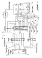
- FIG. 2 is a schematic representation of a motor drive circuit that may be used to drive a motor such as that shown in FIG. 1 ;
- FIG. 3A shows a graphical representation of current, voltage and a digital state representative of sensed voltage in a stator field winding during operation of a motor such as that shown in FIG. 1 ;
- FIG. 3B shows the graphical representation of FIG. 3A , illustrating aspects of masking of a kickback pulse
- FIG. 3C shows the graphical representation of FIG. 3A , illustrating aspects of detection of a kickback pulse.
- the following description relates to control of a 3-phase sensorless BLDC motor and may be suited for use, for example, with machine configurations such as those described in the applicant's U.S. Patent Nos. 6,965,183 ; 7,262,539 ; 7, 288,910 and 7,443,642 .
- BLDC motor The operation of a BLDC motor can be improved through the use of accurate information on the position of the permanent magnet rotor in relation to the stator.
- the position of a permanent magnet rotor may be obtained using sensors such as Hall effect sensors.
- sensors such as Hall effect sensors.
- Benefits of the sensorless solution include, for example, the elimination of position sensors and their connections between the control system and the motor; reduced cost and weight; improved reliability and the removal of temperature limitations imposed by the operational limitations of the position sensors.
- FIG. 1 shows a partial schematic representation of a 3-phase BLDC motor 10, including stator field windings L1, L2 and L3.
- Motor 10 may comprise a rotor (not shown) having at least one permanent magnet (not shown) in addition to a stator comprising field windings L1, L2 and L3. It is to be understood that motor 10 may be an electrical machine that may operate either as a motor or as a generator.
- FIG. 2 shows a motor drive circuit 12 suitable for use in driving motor 10 in accordance with the invention.
- drive circuit 12 includes microprocessor 14, a zero crossing circuit, generally shown at 16, and other components.
- Motor drive circuit 12 can further comprise circuitry useful for controlling motor 10 and commutating an input current through windings L1, L2 and L3 to cause the rotor to rotate in relation to the stator.
- the power phases commutated to field windings L1, L2 and L3 may be identified as phases A, B and C respectively.
- Motor drive circuit 12 may comprise any circuit configuration suitable for zero crossing detection and for determination of rotor position that is known in the art.
- zero crossing circuit 16 may be used to detect occurrences of zero crossings in at least one of windings L1, L2 and L3 of motor 10 and provide feedback to microprocessor 14 of the occurrences of zero crossings.
- a zero crossing occurs when a magnitude of a voltage sensed in a winding (e.g. L1, L2 or L3) changes from a positive value to a negative value or from a negative value to a positive value relative to a neutral.
- zero crossing circuit 16 may comprise voltage comparators 18a, 18b and 18c that may be used, for example, to compare one or more voltages sensed in windings L1, L2 and L3, with corresponding reference voltage(s) in order to detect zero crossings when windings L1, L2 and L3 are non-driven.
- the reference voltage used for comparison may for example be generated virtual neutral 20.
- Zero crossing circuit 16 may also comprise signal conditioning capabilities such as low-pass filtering.
- analog voltages in windings L1, L2 and L3 may be converted to digital signals and fed to an appropriate circuit for detection of the appropriate value.
- suitable circuitry for determining the rotor position may comprise conventional circuitry typically used in conjunction with motor systems having Hall effect position sensors.
- FIG 3A shows exemplary traces representative of current, voltage and a digital state representative of the sensed voltage in winding L1 (phase A) of a motor 10 during commutation.
- the "Phase A Zero Crossing" plot 22 of FIG. 3A shows output of a zero crossing circuit 16 as a digital state showing when the voltage in is either greater or less than zero.
- the output of zero crossing circuit 16 changes state as the phase A voltage crosses from either a positive voltage to a negative voltage or from a negative voltage to a positive voltage.
- Output from zero crossing circuit 16 is provided to microprocessor 14 for further processing and is used for commutation of motor 10.
- motor 10 may be started using, for example, methods that are known in the art.
- Motor drive circuit 12 may be used to control motor 10 by suitably commutating input power through windings L1, L2 and L3 based on rotor position feedback received from zero crossing circuit 16.
- a kickback pulse in the voltage sensed in winding L1 (phase A), generally shown at 26, occurs in the now non-driven winding L1.
- Kickback pulse 26 essentially represents a voltage spike caused by residual current present when current through winding L1 is switched off.
- Kickback pulse 26 comprises two zero crossings, represented by leading edge 28 and falling edge 30.
- Leading edge 28 of kickback pulse 26 occurs when the current to winding L1 is first turned off and falling edge 30 of kickback pulse 26 occurs when the stored energy in winding L1 has decayed.
- Such rotor-induced back-EMF generally has a sinusoidal waveform which may be detected and used to determine the position of the rotor in relation to the stator.
- the rotor-induced back-EMF produces a rotor-induced zero crossing 32 when the rotor-induced back-EMF crosses from either a positive voltage to a negative voltage or from a negative voltage to a positive voltage.
- the rotor-induced zero crossing 32 is representative of the position of the rotor in relation to the stator, and occurs subsequent to falling edge 30 of kickback pulse 26 in FIGS. 3A-3C .
- the detection of rotor-induced zero crossing 32 is of particular interest because it can be used to determine an angular position of the rotor in relation to the stator without requiring a separate sensor such as an encoder or a Hall effect sensor.
- the detection of rotor-induced zero crossing 32 may therefore be used, by the microprocessor 14 for example, in determining the commutation order.
- FIG. 3B illustrates a method for detecting rotor-induced zero crossing 32 which makes use of a masking delay 34.
- Masking delay 34 may be applied by microprocessor 14 and may be of fixed duration sufficient to ensure that the entire kickback pulse 26 has decayed before any zero crossing detection process may occur. Using this method, the first zero crossing that is detected following the delay 34 is presumably rotor-induced zero crossing 32 which follows kickback pulse 26.
- Masking delay 34 may be used to prevent erroneous zero crossing signals from being generated from any portion of kickback pulse 26. Basing the commutation cycle on erroneous zero crossing signals can lead to significant timing errors.
- the duration of a masking delay 34 may be selected to take into account potential changes in the inductance of winding L1 and/or the resistance of the switching circuit which may affect the duration of kickback pulse 26. As a result, masking delay 34 may be selected to be longer than is strictly necessary.
- the use of masking delay 34 to mask the entire kickback pulse 26 may be effective for a particular speed range of motor 10, but as the speed of motor 10 increases, the time interval between falling edge 30 of kickback pulse 26 and rotor-induced zero crossing 32 is reduced. Consequently, as the speed of motor 10 approaches a certain threshold (determined, for example, by the geometry and other characteristics of the circuit components involved) there is a risk that rotor-induced zero crossing 32 may also become masked by masking delay 34.
- Masking rotor-induced zero crossing 32 would prevent rotor-induced zero crossing 32 from being detected and from being used to determine the commutation cycle. Hence, the use of masking delay 34 for masking kickback pulse 26 may limit the maximum speed at which motor 10 can operate.
- FIG. 3C is referenced to describe a novel method of detecting rotor-induced zero crossing 32 according to an exemplary embodiment.
- the present method may be used for generating a signal that is useful in the commutation of motor 10.
- the present method may detect kickback pulse 26 in non-driven winding L1, for example, instead of masking entire kickback pulse 26. Once the kickback pulse 26 has been detected, rotor-induced zero crossing 32 may be detected and the detection of rotor-induced zero crossing 32 may be used to generate a signal useful in the commutation of current through windings L1, L2 and L3 of motor 10.
- the detection of kickback pulse 26 may comprise masking (e.g. ignoring or blanking) only a portion of kickback pulse 26, such as only leading edge 28 of kickback pulse 26, and then detecting falling edge 30 of kickback pulse 26.
- a masking delay 36 of reduced duration may be used to mask only leading edge 28 of kickback pulse 26 as shown in FIG. 3C .
- Reduced masking delay 36 may be applied by microprocessor 14 when for example current to winding L1 is switched off and before initiating any zero crossing detection.
- the detection of falling edge 30 of kickback pulse 26 and of rotor-induced zero crossing 32 may be done using zero crossing circuit 16.
- rotor-induced zero crossing 32 may be detected and used by microprocessor 14 to produce a signal useful in determining a commutation cycle of the motor 10.
- the detection of rotor-induced zero crossing 32 may be correlated to the position of the rotor in relation to the stator of motor 10.
- the signal may be used so that the excitation current provided to any one of windings L1, L2 and L3 may be properly timed and adjusted, if and as necessary, to drive windings L1, L2 and L3 to produce a desired output torque, etc. from motor 10.
- the detection of rotor-induced zero crossings may be conducted on any of or all of the windings L1, L2 and L3.
- kickback pulse 26 or at least a portion of kickback pulse 26, instead of masking of the entire kickback pulse 26, significantly reduces, and in many cases practically eliminates, the risk of rotor-induced zero crossing 32 also becoming masked.
- Such methods and systems may also automatically adjust to variations in the duration of kickback pulse 26 caused by conditions of variable phase inductance or switching circuit resistance. Further, such methods and systems may be used to detect rotor-induced zero crossing 32 at higher operating speeds of motor 10.
- kickback pulse 26 may be detected without the use of any masking delay.
- leading edge 28 of kickback pulse 26 may also be detected instead of being masked. Therefore, leading edge 28 and falling edge 30 of kickback pulse 26 may be detected and counted, and then the third zero crossing detected would be rotor-induced zero crossing 32.
- the cycle time of any circuitry required for detection of zero crossings would need to be faster than the time interval between leading edge 28 and falling edge 30 of kickback pulse 26.
- the method does not specifically require a 3-phase brushless DC motor but may be used with all types of brushless permanent magnet motors.
- a 3-phase winding may be preferred because in many cases it simplifies the associated electronics by allowing the use of commercially-available integrated circuits designed to be used with three Hall effect sensors to sense rotor position.
- Methods and systems according to the disclosure may also be used in conjunction with motors serving as starter motors (not shown) driving a shaft for, as an example, starting a gas turbine engine (not shown).
- motors serving as starter motors (not shown) driving a shaft for, as an example, starting a gas turbine engine (not shown).
- Detection of the kickback pulse may be accomplished through detection of any suitable portion of the kickback pulse.
- the entire kickback pulse does not necessarily need to be sensed.
Abstract
Description
- This invention relates generally to the control of electric motors, and more particularly to systems, devices, and methods useful in the commutation of current through windings of such motors.
- To effectively drive a brushless direct current (BLDC) motor, a motor control system requires accurate information on the position of the rotor in relation to the stator. Sensors such as Hall effect sensors may be used to sense rotor position. However, the use of such sensors increases cost and weight, decreases reliability, and subjects the motor to temperature limitations imposed by the operational limitations of the sensors.
- A form of sensorless control of BLDC motors is known; it typically involves estimation of the rotor speed and/or position based on induced electromotive force (EMF) or back-EMF occurring in a non-energized stator winding. One known technique involves monitoring zero voltage crossings in the EMF generated in the non-energized (non-driven) motor winding in order to determine the position of the rotor. The position of the rotor is then fed back to a commutating circuit to provide a proper commutation sequence to stator windings. Examples of such motors are disclosed in
US Patent No. 5,057,753 to Leuthold et al . andU.S. Patent No. 5,231,338 to Bulgarelli et al . Difficulties are however encountered at high speed applications with known techniques of monitoring zero voltage crossings in the EMF generated in the non-energized motor winding. Improvement in sensorless control is therefore desirable. - The disclosure describes electric machines, and more particularly relates to systems, devices, and methods useful in the commutation of current through windings of electric machines.
- In one aspect, for example, the disclosure describes a method for generating a signal useful in the commutation of current through windings of a brushless electric motor. The method comprises: detecting a kickback pulse in a non-driven winding of the motor; detecting a rotor-induced zero crossing in the non-driven winding following the detection of the kickback pulse; and using the detection of the rotor-induced zero crossing to generate a signal useful in commutation of current through the windings of the motor.
- In another aspect, the disclosure describes a brushless direct current electric motor comprising: a stator and a cooperating permanent magnet rotor, the stator having a plurality of windings; and circuitry configured to: detect a kickback pulse in at least one of the windings when that winding is not driven; detect a rotor-induced zero crossing in the non-driven winding following the detection of the kickback pulse; and use the detection of the rotor-induced zero crossing to generate a signal useful in control of the motor.
- In a further aspect, the disclosure describes a position sensing circuit for use in a brushless electrical motor comprising a stator and a rotor. The position sensing circuit comprises: means for detecting a kickback pulse in a non-driven winding of the stator; means for detecting a rotor-induced zero crossing in the non-driven winding following the kickback pulse; and means for using the detection of the rotor-induced zero crossing to generate a signal representative of the position of the rotor in relation to the stator.
- Further details of these and other aspects of the subject matter of this application will be apparent from the detailed description and drawings included below.
- Reference is now made to the accompanying drawings, in which:
-
FIG. 1 is a partial schematic representation of a 3-phase sensorless brushless direct current (BLDC) motor including stator field windings; -
FIG. 2 is a schematic representation of a motor drive circuit that may be used to drive a motor such as that shown inFIG. 1 ; -
FIG. 3A shows a graphical representation of current, voltage and a digital state representative of sensed voltage in a stator field winding during operation of a motor such as that shown inFIG. 1 ; -
FIG. 3B shows the graphical representation ofFIG. 3A , illustrating aspects of masking of a kickback pulse; and -
FIG. 3C shows the graphical representation ofFIG. 3A , illustrating aspects of detection of a kickback pulse. - Various aspects of preferred embodiments are described through reference to the drawings.
- The following description relates to control of a 3-phase sensorless BLDC motor and may be suited for use, for example, with machine configurations such as those described in the applicant's
U.S. Patent Nos. 6,965,183 ;7,262,539 ;7, 288,910 and7,443,642 . - The operation of a BLDC motor can be improved through the use of accurate information on the position of the permanent magnet rotor in relation to the stator. The position of a permanent magnet rotor may be obtained using sensors such as Hall effect sensors. However, there are applications where sensorless control is desired. Benefits of the sensorless solution include, for example, the elimination of position sensors and their connections between the control system and the motor; reduced cost and weight; improved reliability and the removal of temperature limitations imposed by the operational limitations of the position sensors.
-
FIG. 1 shows a partial schematic representation of a 3-phase BLDC motor 10, including stator field windings L1, L2 and L3.Motor 10 may comprise a rotor (not shown) having at least one permanent magnet (not shown) in addition to a stator comprising field windings L1, L2 and L3. It is to be understood thatmotor 10 may be an electrical machine that may operate either as a motor or as a generator. -
FIG. 2 shows amotor drive circuit 12 suitable for use in drivingmotor 10 in accordance with the invention. In the embodiment shown,drive circuit 12 includesmicroprocessor 14, a zero crossing circuit, generally shown at 16, and other components.Motor drive circuit 12 can further comprise circuitry useful for controllingmotor 10 and commutating an input current through windings L1, L2 and L3 to cause the rotor to rotate in relation to the stator. As shown inFIG 2 ., the power phases commutated to field windings L1, L2 and L3 may be identified as phases A, B and C respectively. -
Motor drive circuit 12 may comprise any circuit configuration suitable for zero crossing detection and for determination of rotor position that is known in the art. In an exemplary analog embodiment, zerocrossing circuit 16 may be used to detect occurrences of zero crossings in at least one of windings L1, L2 and L3 ofmotor 10 and provide feedback tomicroprocessor 14 of the occurrences of zero crossings. A zero crossing occurs when a magnitude of a voltage sensed in a winding (e.g. L1, L2 or L3) changes from a positive value to a negative value or from a negative value to a positive value relative to a neutral. Accordingly, zerocrossing circuit 16 may comprisevoltage comparators crossing circuit 16 may also comprise signal conditioning capabilities such as low-pass filtering. - In an exemplary digital embodiment, analog voltages in windings L1, L2 and L3 may be converted to digital signals and fed to an appropriate circuit for detection of the appropriate value. In any case, suitable circuitry for determining the rotor position may comprise conventional circuitry typically used in conjunction with motor systems having Hall effect position sensors.
-
FIG 3A shows exemplary traces representative of current, voltage and a digital state representative of the sensed voltage in winding L1 (phase A) of amotor 10 during commutation. The "Phase A Zero Crossing"plot 22 ofFIG. 3A shows output of a zerocrossing circuit 16 as a digital state showing when the voltage in is either greater or less than zero. Thus, the output of zerocrossing circuit 16 changes state as the phase A voltage crosses from either a positive voltage to a negative voltage or from a negative voltage to a positive voltage. Output from zerocrossing circuit 16 is provided tomicroprocessor 14 for further processing and is used for commutation ofmotor 10. - During operation,
motor 10 may be started using, for example, methods that are known in the art.Motor drive circuit 12 may be used to controlmotor 10 by suitably commutating input power through windings L1, L2 and L3 based on rotor position feedback received from zerocrossing circuit 16. At every switching action (e.g., when current is switched off, as shown byline 24 inFIGS. 3A-3C ), a kickback pulse in the voltage sensed in winding L1 (phase A), generally shown at 26, occurs in the now non-driven winding L1.Kickback pulse 26 essentially represents a voltage spike caused by residual current present when current through winding L1 is switched off.Kickback pulse 26 occurs due to the magnetic field collapse around the winding L1 as current to winding L1 is switched off and has a duration which is a function of the winding inductance and the dynamic resistance of the switching circuit (e.g. time = L/R).Kickback pulse 26 comprises two zero crossings, represented by leadingedge 28 and fallingedge 30. Leadingedge 28 ofkickback pulse 26 occurs when the current to winding L1 is first turned off and fallingedge 30 ofkickback pulse 26 occurs when the stored energy in winding L1 has decayed. - As the rotor rotates and the permanent magnet of the rotor passes the non-driven winding, such as winding L1 in this case, the motion of the permanent magnet relative to the winding induces back-EMF in the winding L1. Such rotor-induced back-EMF generally has a sinusoidal waveform which may be detected and used to determine the position of the rotor in relation to the stator. The rotor-induced back-EMF produces a rotor-induced zero
crossing 32 when the rotor-induced back-EMF crosses from either a positive voltage to a negative voltage or from a negative voltage to a positive voltage. The rotor-induced zerocrossing 32 is representative of the position of the rotor in relation to the stator, and occurs subsequent to fallingedge 30 ofkickback pulse 26 inFIGS. 3A-3C . The detection of rotor-induced zerocrossing 32 is of particular interest because it can be used to determine an angular position of the rotor in relation to the stator without requiring a separate sensor such as an encoder or a Hall effect sensor. The detection of rotor-induced zerocrossing 32 may therefore be used, by themicroprocessor 14 for example, in determining the commutation order. -
FIG. 3B illustrates a method for detecting rotor-induced zerocrossing 32 which makes use of a maskingdelay 34. Maskingdelay 34 may be applied bymicroprocessor 14 and may be of fixed duration sufficient to ensure that theentire kickback pulse 26 has decayed before any zero crossing detection process may occur. Using this method, the first zero crossing that is detected following thedelay 34 is presumably rotor-induced zerocrossing 32 which followskickback pulse 26. Maskingdelay 34 may be used to prevent erroneous zero crossing signals from being generated from any portion ofkickback pulse 26. Basing the commutation cycle on erroneous zero crossing signals can lead to significant timing errors. - Typically, the duration of a masking
delay 34 may be selected to take into account potential changes in the inductance of winding L1 and/or the resistance of the switching circuit which may affect the duration ofkickback pulse 26. As a result, maskingdelay 34 may be selected to be longer than is strictly necessary. The use of maskingdelay 34 to mask theentire kickback pulse 26 may be effective for a particular speed range ofmotor 10, but as the speed ofmotor 10 increases, the time interval between fallingedge 30 ofkickback pulse 26 and rotor-induced zerocrossing 32 is reduced. Consequently, as the speed ofmotor 10 approaches a certain threshold (determined, for example, by the geometry and other characteristics of the circuit components involved) there is a risk that rotor-induced zerocrossing 32 may also become masked by maskingdelay 34. Masking rotor-induced zerocrossing 32 would prevent rotor-induced zero crossing 32 from being detected and from being used to determine the commutation cycle. Hence, the use of maskingdelay 34 for maskingkickback pulse 26 may limit the maximum speed at which motor 10 can operate. -
FIG. 3C is referenced to describe a novel method of detecting rotor-induced zerocrossing 32 according to an exemplary embodiment. The present method may be used for generating a signal that is useful in the commutation ofmotor 10. The present method may detectkickback pulse 26 in non-driven winding L1, for example, instead of maskingentire kickback pulse 26. Once thekickback pulse 26 has been detected, rotor-induced zerocrossing 32 may be detected and the detection of rotor-induced zerocrossing 32 may be used to generate a signal useful in the commutation of current through windings L1, L2 and L3 ofmotor 10. - In methods according to the disclosure, the detection of
kickback pulse 26 may comprise masking (e.g. ignoring or blanking) only a portion ofkickback pulse 26, such as only leadingedge 28 ofkickback pulse 26, and then detecting fallingedge 30 ofkickback pulse 26. Accordingly, a maskingdelay 36 of reduced duration may be used to mask only leadingedge 28 ofkickback pulse 26 as shown inFIG. 3C . Reduced maskingdelay 36 may be applied bymicroprocessor 14 when for example current to winding L1 is switched off and before initiating any zero crossing detection. As mentioned above, the detection of fallingedge 30 ofkickback pulse 26 and of rotor-induced zerocrossing 32 may be done using zerocrossing circuit 16. Once fallingedge 30 ofkickback pulse 26 has been detected it may be counted, and rotor-induced zerocrossing 32 may be detected and used bymicroprocessor 14 to produce a signal useful in determining a commutation cycle of themotor 10. The detection of rotor-induced zerocrossing 32 may be correlated to the position of the rotor in relation to the stator ofmotor 10. The signal may be used so that the excitation current provided to any one of windings L1, L2 and L3 may be properly timed and adjusted, if and as necessary, to drive windings L1, L2 and L3 to produce a desired output torque, etc. frommotor 10. The detection of rotor-induced zero crossings may be conducted on any of or all of the windings L1, L2 and L3. - Among the many advantages offered by the systems and methods disclosed herein, detection of
kickback pulse 26, or at least a portion ofkickback pulse 26, instead of masking of theentire kickback pulse 26, significantly reduces, and in many cases practically eliminates, the risk of rotor-induced zerocrossing 32 also becoming masked. Such methods and systems may also automatically adjust to variations in the duration ofkickback pulse 26 caused by conditions of variable phase inductance or switching circuit resistance. Further, such methods and systems may be used to detect rotor-induced zerocrossing 32 at higher operating speeds ofmotor 10. - According to other exemplary embodiments,
kickback pulse 26 may be detected without the use of any masking delay. In such cases, leadingedge 28 ofkickback pulse 26 may also be detected instead of being masked. Therefore, leadingedge 28 and fallingedge 30 ofkickback pulse 26 may be detected and counted, and then the third zero crossing detected would be rotor-induced zerocrossing 32. As will be understood by those skilled in the relevant arts, in such cases the cycle time of any circuitry required for detection of zero crossings would need to be faster than the time interval between leadingedge 28 and fallingedge 30 ofkickback pulse 26. - The above descriptions are meant to be exemplary only. Those skilled in the relevant arts will recognize that changes may be made to the embodiments described without departing from the scope of the present disclosure. For example, the method does not specifically require a 3-phase brushless DC motor but may be used with all types of brushless permanent magnet motors. A 3-phase winding may be preferred because in many cases it simplifies the associated electronics by allowing the use of commercially-available integrated circuits designed to be used with three Hall effect sensors to sense rotor position.
- Methods and systems according to the disclosure may also be used in conjunction with motors serving as starter motors (not shown) driving a shaft for, as an example, starting a gas turbine engine (not shown).
- Detection of the kickback pulse may be accomplished through detection of any suitable portion of the kickback pulse. The entire kickback pulse does not necessarily need to be sensed.
- It will also be understood by those skilled in the relevant arts that systems and methods according to the disclosure herein may be used in conjunction with motors having either "inside rotor" or "outside rotor" configurations. Still other modifications which fall within the scope of the invention, which is defined by the claims, will be apparent to those skilled in the art, in light of a review of this disclosure.
Claims (15)
- A method for generating a signal useful in the commutation of current through windings of a brushless electric motor (10), the method comprising:detecting a kickback pulse (26) in a non-driven winding (L1-L3) of the motor;detecting a rotor-induced zero crossing (32) in the non-driven winding following the detection of the kickback pulse; andusing the detection of the rotor-induced zero crossing to generate a signal useful in commutation of current through the windings of the motor.
- The method of claim 1, wherein the detection of the kickback pulse comprises masking a leading edge (28) of the kickback pulse and detecting a falling edge (30) of the kickback pulse.
- The method of claim 2, wherein the masking of the leading edge of the kickback pulse comprises the application of a delay (36).
- The method of claim 2 or 3, wherein the detection of the falling edge of the kickback pulse comprises comparing a voltage sensed in the non-driven winding of the motor to a reference voltage (20).
- The method of claim 1, wherein the detection of the kickback pulse comprises comparing a voltage sensed in the non-driven winding of the motor to a reference voltage (20).
- The method of any preceding claim, wherein the detection of the rotor-induced zero crossing comprises comparing a voltage sensed in the non-driven winding of the motor to a reference voltage (20).
- The method of any preceding claim, further comprising correlating the generated signal to a position of a rotor of the motor in relation to a stator of the motor.
- A brushless direct current electric motor (10) comprising:a stator and a cooperating permanent magnet rotor, the stator having a plurality of windings (L1-L3); andcircuitry (12) configured to: detect a kickback pulse (26) in at least one of the windings when that winding is not driven; detect a rotor-induced zero crossing (32) in the non-driven winding following the detection of the kickback pulse; and use the detection of the rotor-induced zero crossing to generate a signal useful in control of the motor.
- The motor of claim 8, wherein the circuitry is configured to mask a leading edge (28) of the kickback pulse and detect a falling edge (30) of the kickback pulse.
- The motor of claim 9, wherein the circuitry comprises a voltage comparator (18a-c) to compare a voltage sensed in the non-driven winding of the motor to a reference voltage (20) for detecting the falling edge.
- The motor of claim 8, 9 or 10, wherein the circuitry is configured to mask a leading edge of the kickback pulse using a masking delay (36).
- The motor of claim 8, 9, 10 or 11, wherein the circuitry is configured to detect the rotor-induced zero crossing by comparing a voltage sensed in the non-driven winding of the motor to a reference voltage (20).
- The motor of claim 12, wherein the reference voltage is a generated virtual neutral voltage (20).
- The motor of any of claims 8 to 13 wherein the plurality of windings (L1-L3) comprise three phase windings.
- The motor of any of claims 8 to 14 wherein the generated signal is representative of the position of the rotor in relation to the stator.
Priority Applications (1)
| Application Number | Priority Date | Filing Date | Title |
|---|---|---|---|
| EP11250382.6A EP2503684B1 (en) | 2011-03-25 | 2011-03-25 | Control of brushless motor |
Applications Claiming Priority (1)
| Application Number | Priority Date | Filing Date | Title |
|---|---|---|---|
| EP11250382.6A EP2503684B1 (en) | 2011-03-25 | 2011-03-25 | Control of brushless motor |
Publications (2)
| Publication Number | Publication Date |
|---|---|
| EP2503684A1 true EP2503684A1 (en) | 2012-09-26 |
| EP2503684B1 EP2503684B1 (en) | 2018-05-16 |
Family
ID=44681049
Family Applications (1)
| Application Number | Title | Priority Date | Filing Date |
|---|---|---|---|
| EP11250382.6A Active EP2503684B1 (en) | 2011-03-25 | 2011-03-25 | Control of brushless motor |
Country Status (1)
| Country | Link |
|---|---|
| EP (1) | EP2503684B1 (en) |
Citations (11)
| Publication number | Priority date | Publication date | Assignee | Title |
|---|---|---|---|---|
| US5057753A (en) | 1990-06-29 | 1991-10-15 | Seagate Technology, Inc. | Phase commutation circuit for brushless DC motors using a spike insensitive back EMF detection method |
| US5231338A (en) | 1989-11-17 | 1993-07-27 | Sgs-Thomson Microelectronics S.R.L. | Controlling a multiphase brushless motor without position sensors for the rotor, using a system of digital filtering |
| US5717299A (en) * | 1995-06-23 | 1998-02-10 | Sony Corporation | Apparatus for driving a sensorless motor |
| US5859512A (en) * | 1996-01-24 | 1999-01-12 | U.S. Philips Corporation | Drive circuit supplying drive signals to a plurality of windings of a multi-phase d.c. motor |
| US5869944A (en) * | 1995-02-16 | 1999-02-09 | Sony Corporation | Motor driving apparatus |
| US6965183B2 (en) | 2003-05-27 | 2005-11-15 | Pratt & Whitney Canada Corp. | Architecture for electric machine |
| US7071646B1 (en) * | 2005-10-03 | 2006-07-04 | Aimtron Technology Corp. | Sensorless motor control circuit without employing any mask process |
| US7262539B2 (en) | 2004-11-26 | 2007-08-28 | Pratt & Whitney Canada Corp. | Saturation control of electric machine |
| US7288910B2 (en) | 2003-12-01 | 2007-10-30 | Pratt & Whitney Canada Corp. | Sensorless control in a permanent magnet machine |
| US7443642B2 (en) | 2006-05-26 | 2008-10-28 | Pratt & Whitney Canada Corp. | Electric motor control |
| US20090009117A1 (en) * | 2005-04-04 | 2009-01-08 | Toru Someya | Brushless Motor Control Apparatus and Control Method and Motor System |
-
2011
- 2011-03-25 EP EP11250382.6A patent/EP2503684B1/en active Active
Patent Citations (11)
| Publication number | Priority date | Publication date | Assignee | Title |
|---|---|---|---|---|
| US5231338A (en) | 1989-11-17 | 1993-07-27 | Sgs-Thomson Microelectronics S.R.L. | Controlling a multiphase brushless motor without position sensors for the rotor, using a system of digital filtering |
| US5057753A (en) | 1990-06-29 | 1991-10-15 | Seagate Technology, Inc. | Phase commutation circuit for brushless DC motors using a spike insensitive back EMF detection method |
| US5869944A (en) * | 1995-02-16 | 1999-02-09 | Sony Corporation | Motor driving apparatus |
| US5717299A (en) * | 1995-06-23 | 1998-02-10 | Sony Corporation | Apparatus for driving a sensorless motor |
| US5859512A (en) * | 1996-01-24 | 1999-01-12 | U.S. Philips Corporation | Drive circuit supplying drive signals to a plurality of windings of a multi-phase d.c. motor |
| US6965183B2 (en) | 2003-05-27 | 2005-11-15 | Pratt & Whitney Canada Corp. | Architecture for electric machine |
| US7288910B2 (en) | 2003-12-01 | 2007-10-30 | Pratt & Whitney Canada Corp. | Sensorless control in a permanent magnet machine |
| US7262539B2 (en) | 2004-11-26 | 2007-08-28 | Pratt & Whitney Canada Corp. | Saturation control of electric machine |
| US20090009117A1 (en) * | 2005-04-04 | 2009-01-08 | Toru Someya | Brushless Motor Control Apparatus and Control Method and Motor System |
| US7071646B1 (en) * | 2005-10-03 | 2006-07-04 | Aimtron Technology Corp. | Sensorless motor control circuit without employing any mask process |
| US7443642B2 (en) | 2006-05-26 | 2008-10-28 | Pratt & Whitney Canada Corp. | Electric motor control |
Also Published As
| Publication number | Publication date |
|---|---|
| EP2503684B1 (en) | 2018-05-16 |
Similar Documents
| Publication | Publication Date | Title |
|---|---|---|
| CA2727125C (en) | Control of brushless motor | |
| EP3540933B1 (en) | Method for driving sensorless motor | |
| US7893649B2 (en) | Method and circuit arrangement for determining the rotor position of an EC motor in the standstill state | |
| US8593098B2 (en) | Operation of BLDC motors | |
| US6850022B2 (en) | Method and system for determining electronic commutation in brushless DC machines irrespective of the placement of rotor position sensors | |
| US7893640B2 (en) | Brushless motor control apparatus and control method and motor system | |
| JP2010193707A (en) | Method for driving brushless dc motor | |
| CA2772805C (en) | Position sensing circuit for brushless motors | |
| JP5173209B2 (en) | Drive device for a plurality of brushless motors connected in parallel, start method for a plurality of brushless motors connected in parallel, and rotor stop position detection method for a plurality of brushless motors connected in parallel | |
| US10505475B1 (en) | Driving method for single-phase DC brushless motor using sensor only in start-up | |
| EP1806835B1 (en) | Motor driving apparatus | |
| US20200083824A1 (en) | Fixed rotation direction start-up method for single-phase sensorless dc brushless motor | |
| JP5857825B2 (en) | Motor control device | |
| EP1416623B1 (en) | Method and system for determining electronic commutation in brushless DC machines irrespective of the placement of rotor position sensors | |
| EP2503684A1 (en) | Control of brushless motor | |
| CN107852113B (en) | Power conversion device and control method for power conversion device | |
| EP3168981A1 (en) | Rotor position detection apparatus and motor control apparatus | |
| CN107528504B (en) | Method and drive circuit for driving an electric machine comprising a rotor | |
| CN109983690B (en) | Method and circuit arrangement for determining the position of a rotor of an electric motor | |
| KR20170071260A (en) | Method and system for detecting a position of low speed section in sensorless motor | |
| JP4633521B2 (en) | Brushless motor control device, control method, and motor system | |
| US20020070695A1 (en) | Circuit for the sensorless commutation of a dc motor | |
| US20170338803A1 (en) | Filter for a Brushless DC Motor | |
| JP5216185B2 (en) | Brushless motor control device, control method, and motor system | |
| JP2008295260A (en) | Drive device of brushless motor |
Legal Events
| Date | Code | Title | Description |
|---|---|---|---|
| PUAI | Public reference made under article 153(3) epc to a published international application that has entered the european phase |
Free format text: ORIGINAL CODE: 0009012 |
|
| AK | Designated contracting states |
Kind code of ref document: A1 Designated state(s): AL AT BE BG CH CY CZ DE DK EE ES FI FR GB GR HR HU IE IS IT LI LT LU LV MC MK MT NL NO PL PT RO RS SE SI SK SM TR |
|
| AX | Request for extension of the european patent |
Extension state: BA ME |
|
| 17P | Request for examination filed |
Effective date: 20130326 |
|
| GRAP | Despatch of communication of intention to grant a patent |
Free format text: ORIGINAL CODE: EPIDOSNIGR1 |
|
| STAA | Information on the status of an ep patent application or granted ep patent |
Free format text: STATUS: GRANT OF PATENT IS INTENDED |
|
| INTG | Intention to grant announced |
Effective date: 20171127 |
|
| GRAS | Grant fee paid |
Free format text: ORIGINAL CODE: EPIDOSNIGR3 |
|
| GRAA | (expected) grant |
Free format text: ORIGINAL CODE: 0009210 |
|
| STAA | Information on the status of an ep patent application or granted ep patent |
Free format text: STATUS: THE PATENT HAS BEEN GRANTED |
|
| AK | Designated contracting states |
Kind code of ref document: B1 Designated state(s): AL AT BE BG CH CY CZ DE DK EE ES FI FR GB GR HR HU IE IS IT LI LT LU LV MC MK MT NL NO PL PT RO RS SE SI SK SM TR |
|
| REG | Reference to a national code |
Ref country code: GB Ref legal event code: FG4D |
|
| REG | Reference to a national code |
Ref country code: CH Ref legal event code: EP |
|
| REG | Reference to a national code |
Ref country code: IE Ref legal event code: FG4D |
|
| REG | Reference to a national code |
Ref country code: DE Ref legal event code: R096 Ref document number: 602011048350 Country of ref document: DE |
|
| REG | Reference to a national code |
Ref country code: AT Ref legal event code: REF Ref document number: 1000444 Country of ref document: AT Kind code of ref document: T Effective date: 20180615 |
|
| REG | Reference to a national code |
Ref country code: NL Ref legal event code: MP Effective date: 20180516 |
|
| REG | Reference to a national code |
Ref country code: LT Ref legal event code: MG4D |
|
| PG25 | Lapsed in a contracting state [announced via postgrant information from national office to epo] |
Ref country code: FI Free format text: LAPSE BECAUSE OF FAILURE TO SUBMIT A TRANSLATION OF THE DESCRIPTION OR TO PAY THE FEE WITHIN THE PRESCRIBED TIME-LIMIT Effective date: 20180516 Ref country code: NO Free format text: LAPSE BECAUSE OF FAILURE TO SUBMIT A TRANSLATION OF THE DESCRIPTION OR TO PAY THE FEE WITHIN THE PRESCRIBED TIME-LIMIT Effective date: 20180816 Ref country code: ES Free format text: LAPSE BECAUSE OF FAILURE TO SUBMIT A TRANSLATION OF THE DESCRIPTION OR TO PAY THE FEE WITHIN THE PRESCRIBED TIME-LIMIT Effective date: 20180516 Ref country code: SE Free format text: LAPSE BECAUSE OF FAILURE TO SUBMIT A TRANSLATION OF THE DESCRIPTION OR TO PAY THE FEE WITHIN THE PRESCRIBED TIME-LIMIT Effective date: 20180516 Ref country code: LT Free format text: LAPSE BECAUSE OF FAILURE TO SUBMIT A TRANSLATION OF THE DESCRIPTION OR TO PAY THE FEE WITHIN THE PRESCRIBED TIME-LIMIT Effective date: 20180516 Ref country code: BG Free format text: LAPSE BECAUSE OF FAILURE TO SUBMIT A TRANSLATION OF THE DESCRIPTION OR TO PAY THE FEE WITHIN THE PRESCRIBED TIME-LIMIT Effective date: 20180816 |
|
| PG25 | Lapsed in a contracting state [announced via postgrant information from national office to epo] |
Ref country code: HR Free format text: LAPSE BECAUSE OF FAILURE TO SUBMIT A TRANSLATION OF THE DESCRIPTION OR TO PAY THE FEE WITHIN THE PRESCRIBED TIME-LIMIT Effective date: 20180516 Ref country code: NL Free format text: LAPSE BECAUSE OF FAILURE TO SUBMIT A TRANSLATION OF THE DESCRIPTION OR TO PAY THE FEE WITHIN THE PRESCRIBED TIME-LIMIT Effective date: 20180516 Ref country code: RS Free format text: LAPSE BECAUSE OF FAILURE TO SUBMIT A TRANSLATION OF THE DESCRIPTION OR TO PAY THE FEE WITHIN THE PRESCRIBED TIME-LIMIT Effective date: 20180516 Ref country code: LV Free format text: LAPSE BECAUSE OF FAILURE TO SUBMIT A TRANSLATION OF THE DESCRIPTION OR TO PAY THE FEE WITHIN THE PRESCRIBED TIME-LIMIT Effective date: 20180516 Ref country code: GR Free format text: LAPSE BECAUSE OF FAILURE TO SUBMIT A TRANSLATION OF THE DESCRIPTION OR TO PAY THE FEE WITHIN THE PRESCRIBED TIME-LIMIT Effective date: 20180817 |
|
| REG | Reference to a national code |
Ref country code: AT Ref legal event code: MK05 Ref document number: 1000444 Country of ref document: AT Kind code of ref document: T Effective date: 20180516 |
|
| PG25 | Lapsed in a contracting state [announced via postgrant information from national office to epo] |
Ref country code: RO Free format text: LAPSE BECAUSE OF FAILURE TO SUBMIT A TRANSLATION OF THE DESCRIPTION OR TO PAY THE FEE WITHIN THE PRESCRIBED TIME-LIMIT Effective date: 20180516 Ref country code: SK Free format text: LAPSE BECAUSE OF FAILURE TO SUBMIT A TRANSLATION OF THE DESCRIPTION OR TO PAY THE FEE WITHIN THE PRESCRIBED TIME-LIMIT Effective date: 20180516 Ref country code: EE Free format text: LAPSE BECAUSE OF FAILURE TO SUBMIT A TRANSLATION OF THE DESCRIPTION OR TO PAY THE FEE WITHIN THE PRESCRIBED TIME-LIMIT Effective date: 20180516 Ref country code: AT Free format text: LAPSE BECAUSE OF FAILURE TO SUBMIT A TRANSLATION OF THE DESCRIPTION OR TO PAY THE FEE WITHIN THE PRESCRIBED TIME-LIMIT Effective date: 20180516 Ref country code: DK Free format text: LAPSE BECAUSE OF FAILURE TO SUBMIT A TRANSLATION OF THE DESCRIPTION OR TO PAY THE FEE WITHIN THE PRESCRIBED TIME-LIMIT Effective date: 20180516 Ref country code: PL Free format text: LAPSE BECAUSE OF FAILURE TO SUBMIT A TRANSLATION OF THE DESCRIPTION OR TO PAY THE FEE WITHIN THE PRESCRIBED TIME-LIMIT Effective date: 20180516 Ref country code: CZ Free format text: LAPSE BECAUSE OF FAILURE TO SUBMIT A TRANSLATION OF THE DESCRIPTION OR TO PAY THE FEE WITHIN THE PRESCRIBED TIME-LIMIT Effective date: 20180516 |
|
| REG | Reference to a national code |
Ref country code: DE Ref legal event code: R097 Ref document number: 602011048350 Country of ref document: DE |
|
| PG25 | Lapsed in a contracting state [announced via postgrant information from national office to epo] |
Ref country code: SM Free format text: LAPSE BECAUSE OF FAILURE TO SUBMIT A TRANSLATION OF THE DESCRIPTION OR TO PAY THE FEE WITHIN THE PRESCRIBED TIME-LIMIT Effective date: 20180516 Ref country code: IT Free format text: LAPSE BECAUSE OF FAILURE TO SUBMIT A TRANSLATION OF THE DESCRIPTION OR TO PAY THE FEE WITHIN THE PRESCRIBED TIME-LIMIT Effective date: 20180516 |
|
| PLBE | No opposition filed within time limit |
Free format text: ORIGINAL CODE: 0009261 |
|
| STAA | Information on the status of an ep patent application or granted ep patent |
Free format text: STATUS: NO OPPOSITION FILED WITHIN TIME LIMIT |
|
| 26N | No opposition filed |
Effective date: 20190219 |
|
| PGFP | Annual fee paid to national office [announced via postgrant information from national office to epo] |
Ref country code: BG Payment date: 20190321 Year of fee payment: 17 |
|
| PG25 | Lapsed in a contracting state [announced via postgrant information from national office to epo] |
Ref country code: SI Free format text: LAPSE BECAUSE OF FAILURE TO SUBMIT A TRANSLATION OF THE DESCRIPTION OR TO PAY THE FEE WITHIN THE PRESCRIBED TIME-LIMIT Effective date: 20180516 |
|
| PG25 | Lapsed in a contracting state [announced via postgrant information from national office to epo] |
Ref country code: MC Free format text: LAPSE BECAUSE OF FAILURE TO SUBMIT A TRANSLATION OF THE DESCRIPTION OR TO PAY THE FEE WITHIN THE PRESCRIBED TIME-LIMIT Effective date: 20180516 |
|
| REG | Reference to a national code |
Ref country code: CH Ref legal event code: PL |
|
| PG25 | Lapsed in a contracting state [announced via postgrant information from national office to epo] |
Ref country code: AL Free format text: LAPSE BECAUSE OF FAILURE TO SUBMIT A TRANSLATION OF THE DESCRIPTION OR TO PAY THE FEE WITHIN THE PRESCRIBED TIME-LIMIT Effective date: 20180516 Ref country code: LU Free format text: LAPSE BECAUSE OF NON-PAYMENT OF DUE FEES Effective date: 20190325 |
|
| REG | Reference to a national code |
Ref country code: BE Ref legal event code: MM Effective date: 20190331 |
|
| PG25 | Lapsed in a contracting state [announced via postgrant information from national office to epo] |
Ref country code: CH Free format text: LAPSE BECAUSE OF NON-PAYMENT OF DUE FEES Effective date: 20190331 Ref country code: IE Free format text: LAPSE BECAUSE OF NON-PAYMENT OF DUE FEES Effective date: 20190325 Ref country code: LI Free format text: LAPSE BECAUSE OF NON-PAYMENT OF DUE FEES Effective date: 20190331 |
|
| PG25 | Lapsed in a contracting state [announced via postgrant information from national office to epo] |
Ref country code: BE Free format text: LAPSE BECAUSE OF NON-PAYMENT OF DUE FEES Effective date: 20190331 |
|
| PG25 | Lapsed in a contracting state [announced via postgrant information from national office to epo] |
Ref country code: TR Free format text: LAPSE BECAUSE OF FAILURE TO SUBMIT A TRANSLATION OF THE DESCRIPTION OR TO PAY THE FEE WITHIN THE PRESCRIBED TIME-LIMIT Effective date: 20180516 |
|
| PG25 | Lapsed in a contracting state [announced via postgrant information from national office to epo] |
Ref country code: MT Free format text: LAPSE BECAUSE OF NON-PAYMENT OF DUE FEES Effective date: 20190325 Ref country code: PT Free format text: LAPSE BECAUSE OF FAILURE TO SUBMIT A TRANSLATION OF THE DESCRIPTION OR TO PAY THE FEE WITHIN THE PRESCRIBED TIME-LIMIT Effective date: 20180917 |
|
| REG | Reference to a national code |
Ref country code: DE Ref legal event code: R119 Ref document number: 602011048350 Country of ref document: DE |
|
| PG25 | Lapsed in a contracting state [announced via postgrant information from national office to epo] |
Ref country code: DE Free format text: LAPSE BECAUSE OF NON-PAYMENT OF DUE FEES Effective date: 20201001 |
|
| PG25 | Lapsed in a contracting state [announced via postgrant information from national office to epo] |
Ref country code: CY Free format text: LAPSE BECAUSE OF FAILURE TO SUBMIT A TRANSLATION OF THE DESCRIPTION OR TO PAY THE FEE WITHIN THE PRESCRIBED TIME-LIMIT Effective date: 20180516 |
|
| PG25 | Lapsed in a contracting state [announced via postgrant information from national office to epo] |
Ref country code: IS Free format text: LAPSE BECAUSE OF FAILURE TO SUBMIT A TRANSLATION OF THE DESCRIPTION OR TO PAY THE FEE WITHIN THE PRESCRIBED TIME-LIMIT Effective date: 20180916 |
|
| PG25 | Lapsed in a contracting state [announced via postgrant information from national office to epo] |
Ref country code: HU Free format text: LAPSE BECAUSE OF FAILURE TO SUBMIT A TRANSLATION OF THE DESCRIPTION OR TO PAY THE FEE WITHIN THE PRESCRIBED TIME-LIMIT; INVALID AB INITIO Effective date: 20110325 |
|
| PG25 | Lapsed in a contracting state [announced via postgrant information from national office to epo] |
Ref country code: MK Free format text: LAPSE BECAUSE OF FAILURE TO SUBMIT A TRANSLATION OF THE DESCRIPTION OR TO PAY THE FEE WITHIN THE PRESCRIBED TIME-LIMIT Effective date: 20180516 |
|
| PGFP | Annual fee paid to national office [announced via postgrant information from national office to epo] |
Ref country code: FR Payment date: 20230222 Year of fee payment: 13 |
|
| PGFP | Annual fee paid to national office [announced via postgrant information from national office to epo] |
Ref country code: GB Payment date: 20230221 Year of fee payment: 13 |
|
| P01 | Opt-out of the competence of the unified patent court (upc) registered |
Effective date: 20230530 |