EP2503577A1 - Operation switch - Google Patents
Operation switch Download PDFInfo
- Publication number
- EP2503577A1 EP2503577A1 EP10831519A EP10831519A EP2503577A1 EP 2503577 A1 EP2503577 A1 EP 2503577A1 EP 10831519 A EP10831519 A EP 10831519A EP 10831519 A EP10831519 A EP 10831519A EP 2503577 A1 EP2503577 A1 EP 2503577A1
- Authority
- EP
- European Patent Office
- Prior art keywords
- leaf spring
- contact
- push button
- movable
- switch
- Prior art date
- Legal status (The legal status is an assumption and is not a legal conclusion. Google has not performed a legal analysis and makes no representation as to the accuracy of the status listed.)
- Granted
Links
- 238000006073 displacement reaction Methods 0.000 claims abstract description 28
- 230000009194 climbing Effects 0.000 description 11
- 230000003247 decreasing effect Effects 0.000 description 11
- 238000005452 bending Methods 0.000 description 9
- 230000002940 repellent Effects 0.000 description 8
- 239000005871 repellent Substances 0.000 description 8
- 238000004519 manufacturing process Methods 0.000 description 7
- 230000006835 compression Effects 0.000 description 6
- 238000007906 compression Methods 0.000 description 6
- 230000007423 decrease Effects 0.000 description 4
- 230000005489 elastic deformation Effects 0.000 description 4
- 241001481828 Glyptocephalus cynoglossus Species 0.000 description 1
- 230000002159 abnormal effect Effects 0.000 description 1
- 238000012856 packing Methods 0.000 description 1
- 230000001105 regulatory effect Effects 0.000 description 1
- XLYOFNOQVPJJNP-UHFFFAOYSA-N water Substances O XLYOFNOQVPJJNP-UHFFFAOYSA-N 0.000 description 1
Images


Classifications
-
- H—ELECTRICITY
- H01—ELECTRIC ELEMENTS
- H01H—ELECTRIC SWITCHES; RELAYS; SELECTORS; EMERGENCY PROTECTIVE DEVICES
- H01H13/00—Switches having rectilinearly-movable operating part or parts adapted for pushing or pulling in one direction only, e.g. push-button switch
- H01H13/02—Details
- H01H13/12—Movable parts; Contacts mounted thereon
- H01H13/20—Driving mechanisms
-
- H—ELECTRICITY
- H01—ELECTRIC ELEMENTS
- H01H—ELECTRIC SWITCHES; RELAYS; SELECTORS; EMERGENCY PROTECTIVE DEVICES
- H01H1/00—Contacts
- H01H1/12—Contacts characterised by the manner in which co-operating contacts engage
- H01H1/14—Contacts characterised by the manner in which co-operating contacts engage by abutting
- H01H1/24—Contacts characterised by the manner in which co-operating contacts engage by abutting with resilient mounting
- H01H1/26—Contacts characterised by the manner in which co-operating contacts engage by abutting with resilient mounting with spring blade support
-
- H—ELECTRICITY
- H01—ELECTRIC ELEMENTS
- H01H—ELECTRIC SWITCHES; RELAYS; SELECTORS; EMERGENCY PROTECTIVE DEVICES
- H01H13/00—Switches having rectilinearly-movable operating part or parts adapted for pushing or pulling in one direction only, e.g. push-button switch
- H01H13/02—Details
-
- H—ELECTRICITY
- H01—ELECTRIC ELEMENTS
- H01H—ELECTRIC SWITCHES; RELAYS; SELECTORS; EMERGENCY PROTECTIVE DEVICES
- H01H13/00—Switches having rectilinearly-movable operating part or parts adapted for pushing or pulling in one direction only, e.g. push-button switch
- H01H13/02—Details
- H01H13/26—Snap-action arrangements depending upon deformation of elastic members
- H01H13/36—Snap-action arrangements depending upon deformation of elastic members using flexing of blade springs
-
- H—ELECTRICITY
- H01—ELECTRIC ELEMENTS
- H01H—ELECTRIC SWITCHES; RELAYS; SELECTORS; EMERGENCY PROTECTIVE DEVICES
- H01H13/00—Switches having rectilinearly-movable operating part or parts adapted for pushing or pulling in one direction only, e.g. push-button switch
- H01H13/50—Switches having rectilinearly-movable operating part or parts adapted for pushing or pulling in one direction only, e.g. push-button switch having a single operating member
- H01H13/62—Switches having rectilinearly-movable operating part or parts adapted for pushing or pulling in one direction only, e.g. push-button switch having a single operating member the contact returning to its original state upon manual release of a latch
-
- H—ELECTRICITY
- H01—ELECTRIC ELEMENTS
- H01H—ELECTRIC SWITCHES; RELAYS; SELECTORS; EMERGENCY PROTECTIVE DEVICES
- H01H3/00—Mechanisms for operating contacts
- H01H3/02—Operating parts, i.e. for operating driving mechanism by a mechanical force external to the switch
- H01H3/022—Emergency operating parts, e.g. for stop-switch in dangerous conditions
-
- H—ELECTRICITY
- H01—ELECTRIC ELEMENTS
- H01H—ELECTRIC SWITCHES; RELAYS; SELECTORS; EMERGENCY PROTECTIVE DEVICES
- H01H5/00—Snap-action arrangements, i.e. in which during a single opening operation or a single closing operation energy is first stored and then released to produce or assist the contact movement
- H01H5/04—Energy stored by deformation of elastic members
- H01H5/18—Energy stored by deformation of elastic members by flexing of blade springs
Definitions
- the present invention relates generally to an operation switch such as a push button switch and the like, and more particularly to improvements in operation switches for decreasing manufacturing and assembly costs by reducing the number of components thereof.
- JP '527 discloses a switch equipped with a "safety-potential® structure", which is a registered trademark of IDEC Corporation, such that contacts of the switch will not return to a contact state in the event that the switch is damaged.
- the button housing 9 receiving the push button 5 includes the compression spring 55 that biases the cylindrical member 45 at the bottom of the push button 5 toward the switch case 3 in the downward direction and the compression spring 31 that is provided at the bottom of the interlocking member 23 coupled to the bottom of the cylindrical member 45 and that biases the interlocking member 23 below the switch case 3 in the downward direction.
- the interlocking member 23 is biased downwardly via the cylindrical member 45, and due to resiliently repellent force of the compressive spring 31, the interlocking member 23 is biased downward. Thereby, the movable contact 21 is biased toward the side that the movable contact 21 opens relative to the fixed contact 17.
- the present invention has been made in view of these circumstances and its object is to provide an operation switch that can decrease the number of components to reduce a manufacturing and assembly cost.
- An operation switch includes a switch case, anoperatingmemberprovided at the switch case, and a first contact and a second contact held in the switch case. Through operation of the operating member, the first contact and the second contact are made out of contact.
- An opening-biasing means is provided in the switch case that biases the first and second contacts in contact away from each other.
- the opening-biasing means is formed of a leaf spring having the first contact and the second contact.
- the leaf spring as the opening-biasing means is provided with a first contact and a second contact in the switch case at a portion of the leaf spring, there is no need to provide a spring as the opening-biasing means discretely from the contacts and the leaf spring in itself comes to function as a conductive plate with a contact. Thereby, the number of components of the push button switch can be reduced and a manufacturing and assembly cost can be decreased.
- one of the first contact and the second contact may be a fixed contact secured in the switch case and the other of the first contact and the second contact may be a movable contact fitted at an end of the leaf spring and closable and openable relative to the fixed contact.
- the movable contact at an end of the leaf spring is biased to open relative to the fixed contact due to resiliently repellent force of the leaf spring. Also, in this case, contacts with a single-break structure can be achieved thus decreasing the number of contacts.
- the leaf spring may be provided such that the movable contact is located at a position spaced away and disengaged from the fixed contact when displacement of the leaf spring is zero.
- the operation switch may further include a slider in the switch case.
- the slider may be slidable in conjunction with action of the operating member.
- the slider may include a first contacting portion that is disposed on one side of the leaf spring and that comes into contact with the leaf spring to cause the movable contact to contact the fixed contact and a second contacting portion that is disposed on the other side of the leaf spring and that comes into contact with the leaf spring to cause the movable contact to open relative to and move away from the fixed contact.
- the movable contact comes into contact with the fixed contact thus maintaining a contact state of the contacts, and also, due to contact of the second contacting portion of the slider with the leaf spring, the movable contact moves away from the fixed contact thus maintaining a non-contact state of the contacts.
- the leaf spring may be composed of a first leaf spring of a general L-shape and a second leaf spring of a general U-shape.
- the first leaf spring may have a movable contact at one end and a bent portion at an intermediate position between one end and the other end of the first leaf spring.
- the second leaf spring may have one end coupled to a position opposite the movable contact of the first leaf spring and a bent portion at an intermediate position between one end and the other end of the second leaf spring.
- a contacting portion may be provided at a position corresponding to the other end of the second leaf spring in the switch case, the contacting portion being adapted to come into contact with the second leaf spring to cause the movable contact to press-contact the fixed contact.
- the movable contact of the first leaf spring presses against the fixed contact thus maintaining the contacting state of the contacts.
- the biasing means of the movable contact is composed of two kinds of leaf springs, stress imparted to the spring at the time of displacement of the spring can be dispersed compared with the case that the biasing means is composed of a single leaf spring. In such a way, stress exerted to each of the leaf springs can be mitigated.
- opening timing of the movable contact can be adjusted.
- the first leaf spring and the second leaf spring may be adapted to be located at a position in which the movable contact is open relative to and away from the fixed contact when respective displacements of the first leaf spring and the second leaf spring are zero.
- At least one of the respective bent portions of the first leaf spring and the second leaf spring may be formed of an arc-shaped portion that bulges outwardly from a corner of a general L-shape or a bend of a general U-shape.
- rigidity (or rate) of the first and second leaf springs can be adjusted.
- the respective bent portions of the first leaf spring and the second leaf spring may be each formed of an arc-shaped portion that bulges outwardly from a corner of a general L-shape and a bend of a general U-shape. Radius of curvature of the arc-shaped portion of the first leaf spring may be different from radius of curvature of the arc-shaped portion of the second leaf spring.
- radius of curvature of the arc-shaped portion of the first leaf spring is greater than radius of curvature of the arc-shaped portion of the second leaf spring
- bending rigidity of the arc-shaped portion of the first leaf spring is smaller than bending rigidity of the arc-shaped portion of the second leaf spring and the arc-shaped portion of the first leaf spring is thus easier to be bending-deformed than the arc-shaped portion of the second leaf spring.
- the first leaf spring is easier to deform than the second leaf spring. Thereby, opening timing of the contacts can be adjusted.
- the operation switch of the present invention since the first and second contacts are provided in the switch case at a portion of a leaf spring as a contact-opening-biasing means, there is no need to provide a spring as an opening-biasing means discretely from a contact and also the leaf spring in itself comes to function as a conductive plate with a contact. Thereby, the number components can be reduced and a manufacturing and assembly cost can be decreased.
- FIGS. 1 to 9 illustrate a push button switch for emergency stop as an operation switch according to an embodiment of the present invention.
- a push button switch 1 includes a push button 2 as an operating element for an operator to operate, a switch case 3 to hold the push button 2, an operating spindle 4 held in the switch case 3 and adapted to enter the inside of the switch case 3 in association with a press of the push button 2, and a contact unit 5 held in the switch case 3 and engaged with a distal end of the operating spindle 4.
- the push button 2 is a cuplike member having a central hole 2a formed therein and annular grooves 2b, 2c formed around the central hole 2a. Between the central hole 2a and the annular grooves 2b, an annular protrusion 2A is formed.
- the central hole 2a has an engaging projection 2B at a part thereof.
- the switch case 3 is a cylindrical stepped member with openings at opposite ends thereof.
- the switch case 3 includes a large cylindrical portion 30 of a larger diameter which is inserted into the annular groove 2c of the push button 2, and a small cylindrical portion 31 of a smaller diameter smaller than the cylindrical portion 30, the cylindrical portion 31 being formed integrally with the cylindrical portion 30.
- the cylindrical portion 30 has a projection 30a projecting radially inwardly formed therein.
- a waterproof packing 35 is fitted in order to prevent water from entering the inside of the push button 2.
- a part of the outer circumferential surface of the cylindrical portion 31 has an external thread (not shown) formed thereon and a lock nut 36 is screwing engagement with the external thread.
- a gasket 37 is fitted to a stepped surface of the cylindrical portion 30.
- the cylindrical portion 31 of the switch case 3 is inserted into a mounting through hole 10a formed into the control panel 10, and then the lock nut 36 is screwed onto the cylindrical portion 31 from the inside of the control panel 10 to sandwich the control panel 10 between the lock nut 36 and the gasket 37.
- the operating spindle 4 includes a hollow spindle portion 40 extending axially and a flange portion 41 projecting radially outwardly from the spindle portion 40 at a generally central position thereof.
- An end of the spindle portion 40 is inserted into the central hole 2a of the push button 2.
- the end of the spindle portion 40 has a radially extending recess 40B formed therein.
- the engaging projection 2B of the push button 2 is engaged with the recess 40B.
- the other end of the spindle portion 40 is formed with a radially outwardly projecting projection 40a and a radially inwardly projecting projection 40b.
- the projection 40a is engaged with the projection 30a of the cylindrical portion 30 of the switch case 3 at an initial position shown in FIGS. 1A and 1B .
- a pair of bulges 40c which respectively extend radially outwardly.
- the bulges 40c may be placed at equal circumferential spacing from each other.
- a pair of slopes 40c 1 , 40c 2 are formed at opposite ends of each of the bulges 40c.
- the flange portion 41 is formed with an annular groove 41a disposed opposite the annular groove 2b of the push button 2. These annular grooves 2b, 41a have a coil spring 6 fitted therein.
- a trigger spring 7 is provided inside the cylindrical portion 30 of the switch case 3.
- the trigger spring 7 is formed of an annular portion 70 with an opening, and a pair of hook portions 71 of a hook-shape which extend inwardly in parallel from opposite ends of the opening of the annular portion 70.
- the hook portions 71 are respectively in contact with the corresponding slopes 40c 1 of the bulges 40c of the operating spindle 4 from below at the initial position shown in FIGS. 1A and 1B .
- the contact unit 5 includes a cylindrical base 50 fixedly attached to the inside of the cylindrical portion 31 of the switch case 3, and a slider 51 slidably supported in the axial direction in the base 50.
- An end of the slider 51 has an axial portion 52 formed thereon and a distal end of the axial portion 52 is formed with a protrusion 52a protruding radially outwardly.
- the protrusion 52a is engaged with the projection 40b of the spindle portion 40 of the operating spindle 4 at the initial position shown in FIGS. 1A and 1B .
- the slider 51 is adapted to slide axially in the switch case 3 in conjunction with operation of the push button 2.
- the base 50 is provided with a pair of fixed terminals 55A, 56A and a pair of movable terminals 55B, 56B positioned opposite the fixed terminals 55A, 56A, respextively.
- Each of the fixed terminals 55A, 56A is a member of a general L-shape fixedly attached to the base 20 and has a fixed contact (orafirst contact) 55a, 56a provided and fixedly attached in the base 50.
- the movable terminals 55B, 56B have movable contacts (or a second contact) 55b, 56b respectively which are adapted to connect with and disconnect from the fixed contacts 55a, 56a in the base 50.
- a coil spring 8 extending in the axial direction.
- an end of the coil spring 8 presses against a bottom portion of the slider 51 and the other end of the coil spring 8 presses against an inner wall portion of the cylindrical portion 31 of the switch case 3.
- the coil spring 8 is provided as a biasing means to bias the slider 51 downwardly, but it is merely an auxiliary means and not essential in the present invention.
- the fixed terminal 55A is formed of a relatively thick conductive band-shaped member that is bent into an L-shape.
- the fixed contact 55A is provided at a fixed piece 55A 1 that extends in the direction perpendicular to the axial direction inside the base 50.
- the fixed terminal 56A has a similar structure and the detailed explanation will be omitted here.
- the movable terminal 55B is formed of a first leaf spring 550 and a second leaf spring 551.
- the first leaf spring 550 is formed of a relatively thin conductive band-shaped member that is bent into a general L-shape.
- the first leaf spring 550 has the movable contact 55b at one end and a flexure 550a at a generally central position between the one end and the other end of the first leaf spring 550.
- the second leaf spring 551 is generally U-shaped. One end of the second leaf spring 551 is coupled to the first leaf spring 550 on the back side of the movable contact 55b of the first leaf spring 550.
- the second leaf spring 551 has a flexure 551a at a generally central position between the one end and the other end of the second leaf spring 551.
- a movable piece 550 1 of the first leaf spring 550 that extends linearly toward the inside of the base 50 from the flexure 550a has flexibility (i.e. resilience) in the substantially axial direction.
- the second leaf spring 551 is formed in such a way that a portion of the first leaf spring 550 is cut out to be deformed into a generally U-shape.
- the movable piece 551 1 of the second leaf spring 551 extending linearly toward the inside of the base 50 from the flexure 551a has flexibility (i.e. resilience) in the substantially axial direction.
- the movable contact 56B has a similar structure and its detailed explanation will be omitted. In the initial position where the contacts are contacted with each other as shown in FIGS.
- the movable contact 55b is biased to open relative to and disengage from the fixed contact 55a due to resilience of the first leaf spring 550. That is, the first leaf spring 550 functions as an opening and disengaging means of the contacts.
- the slider 51 has a first finger portion 51A and a second finger portion 51B as shown in FIGS. 1B , 2 and 9 .
- the first finger portion 51A is disposed on a side (i.e. away from the push button 2) with respect to the movable piece 550 1 of the first leaf spring 550 and the movable piece 551 1 of the second leaf spring 551.
- the first finger portion 51A is adapted to cause the movable contact 55b to contact the fixed contact 55a by contacting the movable piece 551 1 .
- the second finger portion 51B is disposed on the other side (i.e.
- the second finger portion 51B is adapted to cause the movable contact 55b to move away from the fixed contact 55a by contacting the movable piece 550 1 .
- the first finger portion 51A of the slider 51 comes into contact with the movable piece 551 1 of the second leaf spring 551 to displace the movable piece 551 1 upwardly.
- the movable piece 550 1 of the first leaf spring 550 is displaced upwardly to cause the movable contact 55b to get into contact with the fixed contact 55a.
- displacement of the movable piece 550 1 of the first leaf spring 550 remains zero as well and the movable contact 55b is spaced away from the fixed contact 55a.
- the flexure 550a of the first leaf spring 550 is formed of an arc-shaped portion that bulges outwardly from a generally L-shaped corner of the first leaf spring 550.
- the flexure 551a of the second leaf spring 551 is formed of an arc-shaped portion that bulges outwardly from a generally U-shaped bend of the second leaf spring 551.
- radius of curvature of the arc-shaped portion forming the flexure 550a of the first leaf spring 550 is greater than radius of curvature of the arc-shaped portion forming the flexure 551a of the second leaf spring 551.
- each of the hook portions 71 (see FIG. 8 ) of the trigger spring 7 is in contact with the slope 40c 1 on the lower side of the bulge 40c of the operating spindle 4 from below.
- the first finger portion 51A of the slider 51 comes into contact with the movable piece 551 1 of the second leaf spring 551 and the movable piece 551 1 is displaced upwardly thereby causing the movable piece 550 1 of the first leaf spring 550 to be displaced upwardly such that the movable contact 55b comes into contact with the fixed contact 55a.
- the movable contact 55b at the distal end of the movable piece 550 1 of the first leaf spring 550 is biased to open relative to and move away from the fixed contact 55a due to resilience of the first leaf spring 550. That is, at this juncture, in the state that the first finger portion 51A is not in contact with the movable piece 551 1 of the second leaf spring 551 and displacement of the movable piece 551 1 is zero, displacement of the movable piece 550 1 of the first leaf spring 550 remains zero as well and the movable contact 55b is adapted to be open relative to and spaced away from the fixed contact 55a.
- the hook portions 71 of the trigger spring 7 shift to the state that they are about to disengage from the corresponding slopes 40c 1 of the bulges 40c of the operating spindle 4, in other words, the slopes 40c 1 of the bulges 40c are about to climb over the hook portions 71 of the trigger spring 7.
- the slider 51 is slightly pressed downwardly together with the operating spindle 4 and thus displacement of the movable piece 551 1 of the second leaf spring 551 abutting the first finger portion 51A of the slider 51 is decreased.
- the movable piece 550 1 of the first leaf spring 550 is displaced due to displacement of the movable piece 551 1 of the second leaf spring 551, thereby maintaining the contact state and pressure between the movable contact 55b and the fixed contact 55a.
- the hook portions 71 of the trigger spring 7 shift to the state immediately after they have just disengaged from the corresponding slopes 40c 1 of the bulges 40c of the operating spindle 4, in other words, the slopes 40c 1 of the bulges 40c have just climbed over the hook portions 71 of the trigger spring 7.
- the slider 51 is slightly pressed downwardly together with the operating spindle 4 and thus displacement of the movable piece 551 1 of the second leaf spring 551 abutting the first finger portion 51A of the slider 51 is further decreased from the position immediately before the slopes 40c 1 of the bulges 40c climbs over the hook portions 71 of the trigger spring 7.
- the movable piece 550 1 of the first leaf spring 550 is displaced due to displacement of the movable piece 551 1 of the second leaf spring 551, thereby maintaining the contact state and pressure between the movable contact 55b and the fixed contact 55a.
- resiliently repellent force of the coil spring 6 which has been compression-deformed as the push button 2 is pressed downwardly acts upon the operating spindle 4. Also, the resiliently restoring force due to deformation of the first leaf spring 550 and the second leaf spring 551 biases the slider 51 downwardly.
- first and second leaf springs 550, 551 are placed in the state of free length (i.e. zero displacement) between the first finger portion 51A and the second finger portion 51B of the slider 51. Also, at this juncture, there is formed a gap e between the movable contact 55b and the fixed contact 55a and the contacts move onto the state of out of contact. Then, the push button switch 1 is turned off and the machine tool is put into emergency-shutdown.
- the push button switch 1 shifts to lock position shown in FIGS. 7A and 7B via the position immediately after climbing over hook portions (see FIGS. 5A and 5B ) and the zero-displacement position of leaf spring (see FIGS. 6A and 6B ).
- elastic energy stored in the first and second leaf springs 550, 551 by means of elastic deformation of the movable piece 550 1 due to contact of the second finger portion 51B of the slider 51 in the lock position is predetermined at a far smaller value than elastic energy that has been stored in the first and second leaf springs 550, 551 by means of elastic deformation of the movable pieces 550 1 , 551 1 due to contact of the first finger portion 51A of the slider 51 in the initial position.
- the slider 51 also moves upwardly through the engagement of the projection 40b of the operating spindle 4 with the protrusion 52a of the slider 51.
- the first leaf spring 550 tries to return to the original position due to its resiliently repellent force and the movable piece 550 1 of the first leaf spring 550 is displaced upwardly. Thereafter, due to a press of the first finger portion 51A against the movable piece 551 1 of the second leaf spring 551, first, the movable piece 550 1 of the first leaf spring 550 with the flexure 550a of an arc-shape of a greater radius of curvature is displaced upwardly.
- the first leaf spring 550 as a contact-opening-biasing means is provided with the movable contacts 55b or 56b in the switch case 3, there is no need to provide a spring as an opening-biasing means discretely from the contacts and the first spring 550 per se comes to function as a conductive plate with a contact. Thereby, the number of components of the push button switch can be reduced and a manufacturing and assembly cost can be decreased.
- the contacts can be made a single-break structure thus decreasing the number of contacts.
- the biasing means of the movable contact 55b is formed of two kinds of springs, i.e. the first leaf spring 550 and the second leaf spring 551, a stress exerted to the spring at the time of displacement of the spring can be dispersed compared with the case in which a single leaf spring is used. Thereby, not only each stress imparted to each of the leaf springs can be mitigated but also opening timing of the movable contacts 55b, 56b can be adjusted by properly determining stiffness (or rate) of each of the springs.
- the flexures 550a, 551a of the first and second leaf springs 550, 551 are formed of arc-shaped portions that bulge outwardly from the corner portion of a general L-shape or the bend of a general U-shape, respectively, stiffness of the first and second leaf springs 550, 551 can be adjusted by properly determining radius of curvature of each of the flexures 550a, 551a.
- radius of curvature of the arc-shaped portion of the first leaf spring 550 is determined at a greater value than radius of curvature of the arc-shaped portion of the second leaf spring 551, bending rigidity of the arc-shaped portion of the first leaf spring 550 becomes smaller than bending rigidity of the arc-shaped portion of the second leaf spring 551 and thus the arc-shaped portion of the first leaf spring 550 becomes easier to bending-deform than the arc-shaped portion of the second leaf spring 551.
- the first leaf spring 550 is easier to deform than the second leaf spring 551 thus adjusting opening timing of the contacts.
- radius of curvature of the arc-shaped portion of the second leaf spring 551 is determined at a greater value than radius of curvature of the arc-shapedportion of the first leaf spring 550, bending rigidity of the arc-shaped portion of the second leaf spring 551 becomes smaller than bending rigidity of the arc-shaped portion of the first leaf spring 550 and thus the arc-shaped portion of the second leaf spring 551 becomes easier to bending-deform than the arc-shaped portion of the first leaf spring 550.
- the second leaf spring 551 is easier to deform than the first leaf spring 550 thus adjusting opening timing of the contacts.
- both of the flexures 550a and 551a of the first and second leaf springs 550, 551 were formed of arc-shaped portions that bulge outwardly, but either one of these flexures 550a, 551a may be formed of an arc-shaped portion.
- a leaf spring with a flexure having an arc-shaped portion is easier to deform thus regulating opening timing of the contacts as with the above-mentioned embodiment.
- the movable contact 55b is caused to come into contact with the fixed contact 55a due to contact of the first finger portion 51A with the movable piece 551 1 of the second leaf spring 551, which eliminates the necessity for providing a spring for press contact.
- FIGS. 10 to 12 illustrate a push button switch for emergency stop according to another embodiment of the present invention.
- like reference numbers indicate identical or functionally similar elements.
- only a switch case portion for a push button switch is shown for illustration purposes.
- a fixed terminal 55A' and a movable terminal 55B' in a switch case 3' of a push button switch 1' there are provided a fixed terminal 55A' and a movable terminal 55B' in a switch case 3' of a push button switch 1'.
- the fixed terminal 55B' is a member of a general L-shape provided in the switch case 3' and has a fixed contact (or first contact) 55a' fixed in the switch case 3'.
- the movable terminal 55B' has a movable contact (or second contact) 55b' adapted to engage with and disengage from the fixed contact 55a' in the switch case 3'.
- the fixed terminal 55A' is formed by bending a relatively thick band-shaped conductive plate in an L-shape and the fixed contact 55a' is provided at a fixed piece 55A 1 ' extending in the direction generally perpendicular to the axial direction in the switch case 3'.
- the movable terminal 55B' is formed of a leaf spring 550' composed of a relatively thin band-shaped conductive plate of a general L-shape and has a movable contact 55b' at one end of the leaf spring 550' and a flexure 550a' of a general arc-shape at an intermediate position between the one end and the other end of the leaf spring 550'.
- the leaf spring 550' has a movable piece 550 1 ' which extends toward the inside of the switch case 3' from the flexure 550a' and has resilience in the axial direction.
- the movable contact 55b' as shown in a broken line in FIGS. 10 and 11 , is adapted to be placed at a position in which the movable contact 55b' is open relative to and spaced apart from the fixed contact 55a' at zero displacement (i.e. free length state) of the leaf spring 550' by means of elasticity of the leaf spring 550'.
- a slider 51' slidable in the axial direction in the switch case 3'.
- the slider 51' is adapted to slide in the switch case 3' in conjunction with operation of a push button (not shown), similar to the above-mentioned embodiment.
- the slider 51' is provided with a first finger portion 51A' and a second finger portion 51B'.
- the first finger portion 51A' is disposed on a lower side of the movable piece 550 1 ' of the leaf spring 550' and adapted to come into contact with the movable piece 550 1 ' to cause the movable contact 55b' to contact the fixed contact 55a'.
- the second finger portion 51B' is disposed on an upper side of the movable piece 550 1 ' of the leaf spring 550' and adapted to come into contact with the movable piece 550 1 ' to cause the movable contact 55b' to move away from the fixed contact 55a'.
- the first finger portion 51A' of the slider 51' is in contact with the movable piece 550 1 ' of the leaf spring 550' and the movable piece 550 1 ' is displaced upwardly thus making the movable contact 55b' get into contact with the fixed contact 55a'.
- the movable contact 55b' is open relative to and spaced away from the fixed contact 55a'. That is, the leaf spring 550' functions as an opening-biasing means of contacts.
- the push button switch 1' also has a trigger means similar to the trigger spring of the above-mentioned embodiment.
- the trigger means disengages the axial engagement of an operating spindle in the push button when a stroke of the push button exceeds a certain predetermined extent, and causes the operating spindle to move in the axial direction together with the push button.
- the first finger portion 51A' of the slider 51' is in contact with the movable piece 550 1 ' of the leaf spring 550' and the movable piece 550 1 ' is displaced upwardly thus making the movable contact 55b' come into contact with the fixed contact 55a'.
- the movable contact 55b' at the distal end of the movable piece 550 1 ' of the leaf spring 550' is biased to open relative to and move away from the fixed contact 55a' due to elastic restoring force of the movable piece 550 1 '.
- the trigger means is activated and thus the first finger portion 51A' together with the slider 51' moves downwardly as shown in FIG. 11 .
- displacement of the movable piece 550 1 ' of the leaf spring 550' contacting the first finger portion 51A' is decreased and contact pressure of the movable contact 55b' relative to the fixed contact 55a' is thus decreased, but a contact state of the contacts 55a' and 55b' in contact with each other is maintained.
- the slider 51' is biased downwardly due to elastic restoring force of the movable piece 550 1 ' of the leaf spring 550'.
- elastic energy stored in the leaf spring 550' in the lock position by means of elastic deformation of the movable piece 550 1 ' due to contact of the second finger portion 51B' of the slider 51' is predetermined at a smaller value than elastic energy that has been stored in the leaf spring 550' in the initial position by means of elastic deformation of the movable piece 550 1 ' due to contact of the first finger portion 51A' of the slider 51'.
- the operating switch according to the present invention was applied to a push-button-type emergency switch, but the application of the present invention is not limited to an emergency switch and the present invention is also applicable to a general normally closed switch in which normally closed contacts are caused to be open due to operation of a push button. Moreover, the present invention also has application to switches such as a selector switch, a cam switch, a safety switch and the like.
- the present invention is useful for an operation switch such as a push button switch and the like, and suitable especially to a switch that requires decrease in cost by reducing the number of components.
Abstract
Description
- The present invention relates generally to an operation switch such as a push button switch and the like, and more particularly to improvements in operation switches for decreasing manufacturing and assembly costs by reducing the number of components thereof.
- Generally, in a control panel for mechanical equipment such as machine tools and the like, a push-button-type emergency stop switch is provided to emergency-stop mechanical equipment at the time of abnormal circumstances. In such a push-button-types witch, for example, Japanese patent application laying-open publication No.
2003-303527 - As shown in
figures 1 and2 of JP '527, the button housing 9 receiving thepush button 5 includes the compression spring 55 that biases the cylindrical member 45 at the bottom of thepush button 5 toward theswitch case 3 in the downward direction and thecompression spring 31 that is provided at the bottom of the interlocking member 23 coupled to the bottom of the cylindrical member 45 and that biases the interlocking member 23 below theswitch case 3 in the downward direction. - In this case, due to resiliently repellent force of the compressive spring 55, the interlocking member 23 is biased downwardly via the cylindrical member 45, and due to resiliently repellent force of the
compressive spring 31, the interlocking member 23 is biased downward. Thereby, the movable contact 21 is biased toward the side that the movable contact 21 opens relative to the fixed contact 17. - Through operation of the
push button 5, as the movable contact 21 moves away from and opens relative to the fixed contact 17, the amount of deformation ofrespective compression springs 55, 31 decreases, and elastic energy ofrespective compression springs 55, 31 thus decreases. That is, elastic energy ofrespective compression springs 55, 31 after opening of the contacts is smaller than elastic energy ofrespective compression springs 55, 31 before opening of the contacts. - Therefore, according to the push-button-type switch shown in JP '527, even in the event that the switch is damaged, the contacts will not return to the contact state again thereby displaying "safety-potential® function" as a push button switch.
- However, in the abovementioned structure of prior art, there needs to be provided a spring discretely from the contacts that biases the movable contact away from the fixed contact, and as a result it is disadvantageous that the number of components increases and thus a manufacturing and assembly cost increases.
- The present invention has been made in view of these circumstances and its object is to provide an operation switch that can decrease the number of components to reduce a manufacturing and assembly cost.
- An operation switch according to the present invention includes a switch case, anoperatingmemberprovided at the switch case, and a first contact and a second contact held in the switch case. Through operation of the operating member, the first contact and the second contact are made out of contact. An opening-biasing means is provided in the switch case that biases the first and second contacts in contact away from each other. The opening-biasing means is formed of a leaf spring having the first contact and the second contact.
- According to the present invention, since the leaf spring as the opening-biasing means is provided with a first contact and a second contact in the switch case at a portion of the leaf spring, there is no need to provide a spring as the opening-biasing means discretely from the contacts and the leaf spring in itself comes to function as a conductive plate with a contact. Thereby, the number of components of the push button switch can be reduced and a manufacturing and assembly cost can be decreased.
- In the operation switch, one of the first contact and the second contact may be a fixed contact secured in the switch case and the other of the first contact and the second contact may be a movable contact fitted at an end of the leaf spring and closable and openable relative to the fixed contact.
- In this case, the movable contact at an end of the leaf spring is biased to open relative to the fixed contact due to resiliently repellent force of the leaf spring. Also, in this case, contacts with a single-break structure can be achieved thus decreasing the number of contacts.
- In the operation switch, the leaf spring may be provided such that the movable contact is located at a position spaced away and disengaged from the fixed contact when displacement of the leaf spring is zero.
- The operation switch may further include a slider in the switch case. The slider may be slidable in conjunction with action of the operating member. The slider may include a first contacting portion that is disposed on one side of the leaf spring and that comes into contact with the leaf spring to cause the movable contact to contact the fixed contact and a second contacting portion that is disposed on the other side of the leaf spring and that comes into contact with the leaf spring to cause the movable contact to open relative to and move away from the fixed contact.
- In this case, due to contact of the first contacting portion of the slider with the leaf spring, the movable contact comes into contact with the fixed contact thus maintaining a contact state of the contacts, and also, due to contact of the second contacting portion of the slider with the leaf spring, the movable contact moves away from the fixed contact thus maintaining a non-contact state of the contacts.
- In the operation switch, the leaf spring may be composed of a first leaf spring of a general L-shape and a second leaf spring of a general U-shape. The first leaf spring may have a movable contact at one end and a bent portion at an intermediate position between one end and the other end of the first leaf spring. The second leaf spring may have one end coupled to a position opposite the movable contact of the first leaf spring and a bent portion at an intermediate position between one end and the other end of the second leaf spring. A contacting portion may be provided at a position corresponding to the other end of the second leaf spring in the switch case, the contacting portion being adapted to come into contact with the second leaf spring to cause the movable contact to press-contact the fixed contact.
- In this case, due to contact of the contacting portion in the switch case with the other end of the second leaf spring, the movable contact of the first leaf spring presses against the fixed contact thus maintaining the contacting state of the contacts. Also, in this case, since the biasing means of the movable contact is composed of two kinds of leaf springs, stress imparted to the spring at the time of displacement of the spring can be dispersed compared with the case that the biasing means is composed of a single leaf spring. In such a way, stress exerted to each of the leaf springs can be mitigated. Moreover, in this case, by properly predetermining rigidity (or rate) of each of the leaf springs, opening timing of the movable contact can be adjusted.
- In the operation switch, the first leaf spring and the second leaf spring may be adapted to be located at a position in which the movable contact is open relative to and away from the fixed contact when respective displacements of the first leaf spring and the second leaf spring are zero.
- In the operation switch, at least one of the respective bent portions of the first leaf spring and the second leaf spring may be formed of an arc-shaped portion that bulges outwardly from a corner of a general L-shape or a bend of a general U-shape.
- In this case, by properly predetermining radius of curvature of the arc-shaped portion, rigidity (or rate) of the first and second leaf springs can be adjusted.
- In the operation switch, the respective bent portions of the first leaf spring and the second leaf spring may be each formed of an arc-shaped portion that bulges outwardly from a corner of a general L-shape and a bend of a general U-shape. Radius of curvature of the arc-shaped portion of the first leaf spring may be different from radius of curvature of the arc-shaped portion of the second leaf spring.
- For example, in the event that radius of curvature of the arc-shaped portion of the first leaf spring is greater than radius of curvature of the arc-shaped portion of the second leaf spring, bending rigidity of the arc-shaped portion of the first leaf spring is smaller than bending rigidity of the arc-shaped portion of the second leaf spring and the arc-shaped portion of the first leaf spring is thus easier to be bending-deformed than the arc-shaped portion of the second leaf spring. In this case, when the contacting portion in the switch case has come into contact with the other end of the second leaf spring, the first leaf spring is easier to deform than the second leaf spring. Thereby, opening timing of the contacts can be adjusted.
- In contrast, in the event that radius of curvature of the arc-shaped portion of the second leaf spring is greater than radius of curvature of the arc-shaped portion of the first leaf spring, bending rigidity of the arc-shaped portion of the second leaf spring is smaller than bending rigidity of the arc-shaped portion of the first leaf spring and the arc-shaped portion of the second leaf spring is thus easier to be bending-deformed than the arc-shaped portion of the first leaf spring. In this case, when the contacting portion in the switch case has come into contact with the other end of the second leaf spring, the second leaf spring is easier to deform than the first leaf spring. Thereby, opening timing of the contacts can be adjusted.
- As above-mentioned, according to the operation switch of the present invention, since the first and second contacts are provided in the switch case at a portion of a leaf spring as a contact-opening-biasing means, there is no need to provide a spring as an opening-biasing means discretely from a contact and also the leaf spring in itself comes to function as a conductive plate with a contact. Thereby, the number components can be reduced and a manufacturing and assembly cost can be decreased.
-
-
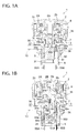
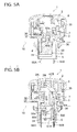
FIG. 1A is a longitudinal sectional view of a push button switch at an initial position along the longitudinal centerline according to an embodiment of the present invention; -
FIG. 1B is a longitudinal sectional view of the push button switch ofFIG. 1A taken along the longitudinal line passing through the contacts thereof; -
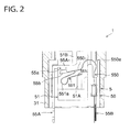
Fig. 2 is an enlarged view of the push button switch ofFIG. 1B illustrating a switch case portion thereof; -
FIG. 2A is an enlarged view of the push button switch ofFIG. 2 illustrating a contact portion thereof; -
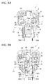
FIG. 3A is a longitudinal sectional view of a push button switch at a preliminary press position along the longitudinal centerline according to an embodiment of the present invention; -
FIG. 3B is a longitudinal sectional view of the push button switch ofFIG. 3A taken along the longitudinal line passing through the contacts thereof; -
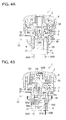
Fig. 4A is a longitudinal sectional view of a push button switch taken along the longitudinal centerline at a position immediately before climbing over hook portions according to an embodiment of the present invention; -
FIG. 4B is a longitudinal sectional view of the push button switch ofFIG. 4A taken along the longitudinal line passing through the contacts thereof; -
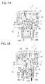
Fig. 5A is a longitudinal sectional view of a push button switch taken along the longitudinal centerline at a position immediately after climbing over hook portions and immediately before a lock position according to an embodiment of the present invention; -
FIG. 5B is a longitudinal sectional view of the push button switch ofFIG. 5A taken along the longitudinal line passing through the contacts thereof; -
FIG. 6 is an enlarged longitudinal sectional view of a portion of a push button switch taken along the longitudinal line passing through the contacts thereof according to an embodiment of the present invention, illustrating the state at the moment when displacement of each of the leaf springs has become zero due to a travel of a slider immediately before a lock position; -
FIG. 7A is a longitudinal sectional view of a push button switch at a lock position along the longitudinal centerline according to an embodiment of the present invention; -
FIG. 7B is a longitudinal sectional view of the push button switch ofFIG. 7A taken along the longitudinal line passing through the contacts thereof; -
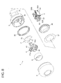
FIG. 8 is an exploded perspective view of a push button switch according to an embodiment of the present invention; -
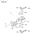
FIG. 9 is an exploded perspective view of contact units of the push button switch ofFIG. 8 ; -
FIG. 10 is a longitudinal sectional view of a push button switch at an initial position taken along the longitudinal line passing through the contacts thereof according to another embodiment of the present invention, which corresponds toFIGS. 1B and2 ; -
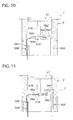
Fig. 11 is a longitudinal sectional view of a push button switch taken along the longitudinal line passing through the contacts thereof at a position immediately after climbing over hook portions and immediately before a lock position according to another embodiment of the present invention, which corresponds toFIG. 5B ; and -
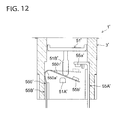
FIG. 12 is a longitudinal sectional view of a push button switch at a lock position along the longitudinal line passing through the contacts thereof according to another embodiment of the present invention, which corresponds toFIG. 7B . - Embodiments of the present invention will be hereinafter described in accordance with the appended drawings.
-
FIGS. 1 to 9 illustrate a push button switch for emergency stop as an operation switch according to an embodiment of the present invention. - As shown in
FIGS. 1A, 1B and8 , apush button switch 1 includes apush button 2 as an operating element for an operator to operate, aswitch case 3 to hold thepush button 2, an operatingspindle 4 held in theswitch case 3 and adapted to enter the inside of theswitch case 3 in association with a press of thepush button 2, and acontact unit 5 held in theswitch case 3 and engaged with a distal end of the operatingspindle 4. - The
push button 2 is a cuplike member having acentral hole 2a formed therein andannular grooves central hole 2a. Between thecentral hole 2a and theannular grooves 2b, anannular protrusion 2A is formed. Thecentral hole 2a has an engagingprojection 2B at a part thereof. Theswitch case 3 is a cylindrical stepped member with openings at opposite ends thereof. Theswitch case 3 includes a largecylindrical portion 30 of a larger diameter which is inserted into theannular groove 2c of thepush button 2, and a smallcylindrical portion 31 of a smaller diameter smaller than thecylindrical portion 30, thecylindrical portion 31 being formed integrally with thecylindrical portion 30. Thecylindrical portion 30 has aprojection 30a projecting radially inwardly formed therein. On an outer circumferential surface of thecylindrical portion 30, awaterproof packing 35 is fitted in order to prevent water from entering the inside of thepush button 2. A part of the outer circumferential surface of thecylindrical portion 31 has an external thread (not shown) formed thereon and alock nut 36 is screwing engagement with the external thread. Agasket 37 is fitted to a stepped surface of thecylindrical portion 30. - When installing the
push button switch 1 to acontrol panel 10 of a machine tool or the like, first, thecylindrical portion 31 of theswitch case 3 is inserted into a mounting throughhole 10a formed into thecontrol panel 10, and then thelock nut 36 is screwed onto thecylindrical portion 31 from the inside of thecontrol panel 10 to sandwich thecontrol panel 10 between thelock nut 36 and thegasket 37. - The operating
spindle 4 includes ahollow spindle portion 40 extending axially and aflange portion 41 projecting radially outwardly from thespindle portion 40 at a generally central position thereof. An end of thespindle portion 40 is inserted into thecentral hole 2a of thepush button 2. Also, the end of thespindle portion 40 has a radially extendingrecess 40B formed therein. The engagingprojection 2B of thepush button 2 is engaged with therecess 40B. The other end of thespindle portion 40 is formed with a radially outwardly projectingprojection 40a and a radially inwardly projectingprojection 40b. Theprojection 40a is engaged with theprojection 30a of thecylindrical portion 30 of theswitch case 3 at an initial position shown inFIGS. 1A and 1B . At a generally central position of thespindle portion 40, there are formed a pair ofbulges 40c which respectively extend radially outwardly. Thebulges 40c may be placed at equal circumferential spacing from each other. A pair ofslopes bulges 40c. Theflange portion 41 is formed with anannular groove 41a disposed opposite theannular groove 2b of thepush button 2. Theseannular grooves coil spring 6 fitted therein. - Inside the
cylindrical portion 30 of theswitch case 3, atrigger spring 7 is provided. As shown inFIG. 8 , thetrigger spring 7 is formed of anannular portion 70 with an opening, and a pair ofhook portions 71 of a hook-shape which extend inwardly in parallel from opposite ends of the opening of theannular portion 70. Thehook portions 71 are respectively in contact with thecorresponding slopes 40c1 of thebulges 40c of the operating spindle 4 from below at the initial position shown inFIGS. 1A and 1B . - The
contact unit 5 includes acylindrical base 50 fixedly attached to the inside of thecylindrical portion 31 of theswitch case 3, and aslider 51 slidably supported in the axial direction in thebase 50. An end of theslider 51 has anaxial portion 52 formed thereon and a distal end of theaxial portion 52 is formed with aprotrusion 52a protruding radially outwardly. Theprotrusion 52a is engaged with theprojection 40b of thespindle portion 40 of the operatingspindle 4 at the initial position shown inFIGS. 1A and 1B . Thereby, theslider 51 is adapted to slide axially in theswitch case 3 in conjunction with operation of thepush button 2. - As shown in
FIG. 9 , thebase 50 is provided with a pair of fixedterminals movable terminals terminals terminals base 50. Themovable terminals contacts base 50. Also, inside thebase 50, there is provided acoil spring 8 extending in the axial direction. As shown inFIG. 1A , an end of thecoil spring 8 presses against a bottom portion of theslider 51 and the other end of thecoil spring 8 presses against an inner wall portion of thecylindrical portion 31 of theswitch case 3. Thecoil spring 8 is provided as a biasing means to bias theslider 51 downwardly, but it is merely an auxiliary means and not essential in the present invention. - As shown in
FIGS. 2 and2A , the fixed terminal 55A is formed of a relatively thick conductive band-shaped member that is bent into an L-shape. The fixedcontact 55A is provided at afixed piece 55A1 that extends in the direction perpendicular to the axial direction inside thebase 50. In addition, the fixed terminal 56A has a similar structure and the detailed explanation will be omitted here. - The
movable terminal 55B is formed of afirst leaf spring 550 and asecond leaf spring 551. Thefirst leaf spring 550 is formed of a relatively thin conductive band-shaped member that is bent into a general L-shape. Thefirst leaf spring 550 has themovable contact 55b at one end and aflexure 550a at a generally central position between the one end and the other end of thefirst leaf spring 550. Thesecond leaf spring 551 is generally U-shaped. One end of thesecond leaf spring 551 is coupled to thefirst leaf spring 550 on the back side of themovable contact 55b of thefirst leaf spring 550. Thesecond leaf spring 551 has aflexure 551a at a generally central position between the one end and the other end of thesecond leaf spring 551. - A
movable piece 5501 of thefirst leaf spring 550 that extends linearly toward the inside of the base 50 from theflexure 550a has flexibility (i.e. resilience) in the substantially axial direction. Also, thesecond leaf spring 551 is formed in such a way that a portion of thefirst leaf spring 550 is cut out to be deformed into a generally U-shape. Themovable piece 5511 of thesecond leaf spring 551 extending linearly toward the inside of the base 50 from theflexure 551a has flexibility (i.e. resilience) in the substantially axial direction. In addition, themovable contact 56B has a similar structure and its detailed explanation will be omitted. In the initial position where the contacts are contacted with each other as shown inFIGS. 1A, 1B ,2 and2A , themovable contact 55b is biased to open relative to and disengage from the fixedcontact 55a due to resilience of thefirst leaf spring 550. That is, thefirst leaf spring 550 functions as an opening and disengaging means of the contacts. - On the other hand, the
slider 51 has afirst finger portion 51A and asecond finger portion 51B as shown inFIGS. 1B ,2 and9 . Thefirst finger portion 51A is disposed on a side (i.e. away from the push button 2) with respect to themovable piece 5501 of thefirst leaf spring 550 and themovable piece 5511 of thesecond leaf spring 551. Thefirst finger portion 51A is adapted to cause themovable contact 55b to contact thefixed contact 55a by contacting themovable piece 5511. Thesecond finger portion 51B is disposed on the other side (i.e. close to the push button 2) with respect to themovable piece 5501 of thefirst leaf spring 550 and themovable piece 5511 of thesecond leaf spring 551. Thesecond finger portion 51B is adapted to cause themovable contact 55b to move away from the fixedcontact 55a by contacting themovable piece 5501. - In the initial position shown in
FIGS. 1B and2 , thefirst finger portion 51A of theslider 51 comes into contact with themovable piece 5511 of thesecond leaf spring 551 to displace themovable piece 5511 upwardly. Thereby, themovable piece 5501 of thefirst leaf spring 550 is displaced upwardly to cause themovable contact 55b to get into contact with the fixedcontact 55a. Additionally, at this juncture, in the state that thefirst finger portion 51A is not in contact with themovable piece 5511 and displacement of themovable piece 5511 is zero, displacement of themovable piece 5501 of thefirst leaf spring 550 remains zero as well and themovable contact 55b is spaced away from the fixedcontact 55a. - As is clearly shown in
FIG. 2A , theflexure 550a of thefirst leaf spring 550 is formed of an arc-shaped portion that bulges outwardly froma generally L-shaped corner of thefirst leaf spring 550. Similarly, theflexure 551a of thesecond leaf spring 551 is formed of an arc-shaped portion that bulges outwardly from a generally U-shaped bend of thesecond leaf spring 551. Also, in this embodiment, radius of curvature of the arc-shaped portion forming theflexure 550a of thefirst leaf spring 550 is greater than radius of curvature of the arc-shaped portion forming theflexure 551a of thesecond leaf spring 551. - Then, operation of the above-mentioned
push button switch 1 will be explained in the operational order with reference toFIGS. 1 to 7 . - At the initial position of the
push button switch 1 in which thepush button 2 is not pressed, as described in reference toFIG. 1A , each of the hook portions 71 (seeFIG. 8 ) of thetrigger spring 7 is in contact with theslope 40c1 on the lower side of thebulge 40c of the operating spindle 4 from below. Also, as explained in reference toFIGS. 1B and2 , thefirst finger portion 51A of theslider 51 comes into contact with themovable piece 5511 of thesecond leaf spring 551 and themovable piece 5511 is displaced upwardly thereby causing themovable piece 5501 of thefirst leaf spring 550 to be displaced upwardly such that themovable contact 55b comes into contact with the fixedcontact 55a. - On this occasion, the
movable contact 55b at the distal end of themovable piece 5501 of thefirst leaf spring 550 is biased to open relative to and move away from the fixedcontact 55a due to resilience of thefirst leaf spring 550. That is, at this juncture, in the state that thefirst finger portion 51A is not in contact with themovable piece 5511 of thesecond leaf spring 551 and displacement of themovable piece 5511 is zero, displacement of themovable piece 5501 of thefirst leaf spring 550 remains zero as well and themovable contact 55b is adapted to be open relative to and spaced away from the fixedcontact 55a. - At a preliminary press position in which only the
push button 2 is slightly pressed from the state of the initial position, as shown inFIGS. 3A and 3B , thepush button 2 is pushed downwardly against the force of thecoil spring 6 and theannular protrusion 2A of thepush button 2 comes into contact with theflange portion 41 of the operatingspindle 4. On this occasion, the operatingspindle 4 is not pushed downwardly and thus the axial positions of the operatingspindle 4 and theslider 51 are not changed from the initial position. - Therefore, positional relation between each of the
hook portions 71 of thetrigger spring 7 and theslope 40c1 of thebulge 40c of the operatingspindle 4, displacement of themovable piece 5511 of thesecond leaf spring 551, displacement of themovable piece 5501 of thefirst leaf spring 550, and the contact state and pressure between themovable contact 55b and the fixedcontact 55a are not changed from the initial position. - When the
push button 2 is pushed further downwardly from the preliminary press position, thepush button switch 1 shifts to the position immediately before theslopes 40c1 climb overhook portions 71 shown inFIGS. 4A and 4B . At this juncture, the operatingspindle 4 is slightly pushed downwardly together with thepush button 2 and thus each of theslopes 40c1 of thebulges 40c of the operatingspindle 4 enlarges each of thehook portions 71 of thetrigger spring 7 radially outwardly. As a result of this, thehook portions 71 of thetrigger spring 7 shift to the state that they are about to disengage from thecorresponding slopes 40c1 of thebulges 40c of the operatingspindle 4, in other words, theslopes 40c1 of thebulges 40c are about to climb over thehook portions 71 of thetrigger spring 7. - Also, on this occasion, as the
push button 2 is pressed downwardly, theslider 51 is slightly pressed downwardly together with the operatingspindle 4 and thus displacement of themovable piece 5511 of thesecond leaf spring 551 abutting thefirst finger portion 51A of theslider 51 is decreased. However, in this case as well, themovable piece 5501 of thefirst leaf spring 550 is displaced due to displacement of themovable piece 5511 of thesecond leaf spring 551, thereby maintaining the contact state and pressure between themovable contact 55b and the fixedcontact 55a. - When the
push button 2 is pushed further downwardly from the position immediately before climbing over hook portions, thepush button switch 1 shifts to the position immediately after theslopes 40c1 have climbed overhook portions 71 shown inFIGS. 5A and 5B . At this juncture, the operatingspindle 4 is slightly pushed downwardly together with thepush button 2 and thus each of theslopes 40c1 of thebulges 40c of the operatingspindle 4 further enlarges each of thehook portions 71 of thetrigger spring 7 radially outwardly. As a result of this, thehook portions 71 of thetrigger spring 7 shift to the state immediately after they have just disengaged from thecorresponding slopes 40c1 of thebulges 40c of the operatingspindle 4, in other words, theslopes 40c1 of thebulges 40c have just climbed over thehook portions 71 of thetrigger spring 7. - Also, on this occasion, as the
push button 2 is pressed downwardly, theslider 51 is slightly pressed downwardly together with the operatingspindle 4 and thus displacement of themovable piece 5511 of thesecond leaf spring 551 abutting thefirst finger portion 51A of theslider 51 is further decreased from the position immediately before theslopes 40c1 of thebulges 40c climbs over thehook portions 71 of thetrigger spring 7. However, in this case as well, themovable piece 5501 of thefirst leaf spring 550 is displaced due to displacement of themovable piece 5511 of thesecond leaf spring 551, thereby maintaining the contact state and pressure between themovable contact 55b and the fixedcontact 55a. - Likewise, in the above-mentioned position immediately after climbing over hook portions from the position immediately before climbing over hook portions, resiliently repellent force of the
coil spring 6 which has been compression-deformed as thepush button 2 is pressed downwardly acts upon the operatingspindle 4. Also, the resiliently restoring force due to deformation of thefirst leaf spring 550 and thesecond leaf spring 551 biases theslider 51 downwardly. - The moment when the
hook portions 71 of thetrigger spring 7 have disengaged from thecorresponding slopes 40c1 of thebulges 40c of the operatingspindle 4 placed in the position immediately after climbing over hook portions, the operatingspindle 4 moves downwardly due to the resiliently repellent force of thecoil spring 6, the resiliently restoring force of the first andsecond leaf springs coil spring 8. Thereby, thefirst finger portion 51A of theslider 51 leaves themovable piece 5511 of thesecond leaf spring 551 and then as shown inFIG. 6 , thepush button switch 1 shifts to the position of zero displacement of the first andsecond leaf springs second leaf springs first finger portion 51A and thesecond finger portion 51B of theslider 51. Also, at this juncture, there is formed a gap e between themovable contact 55b and the fixedcontact 55a and the contacts move onto the state of out of contact. Then, thepush button switch 1 is turned off and the machine tool is put into emergency-shutdown. - When the
push button 2 is pushed downwardly from the position immediately before climbing over hook portions shown inFIGS. 4A and 4B , thepush button switch 1 shifts to lock position shown inFIGS. 7A and 7B via the position immediately after climbing over hook portions (seeFIGS. 5A and 5B ) and the zero-displacement position of leaf spring (seeFIGS. 6A and 6B ). - In this lock position, as shown in
FIGS. 7A and 7B , the operatingspindle 4 travels further downwardly from the position (not shown) ofFIG. 6 due to the resiliently repellent force of thecoil spring 6. At this juncture, theslopes 40c2 on the upper side of thebulges 40c move onto the position opposite thecorresponding hook portions 71 of thetrigger spring 7. Then, thehook portions 71 of thetrigger spring 7 that has been enlarged contract and return to the original state due to their resiliently restoring force and thehook portions 71 thus contact theslopes 40c2 of thebulges 40c. Also, at this juncture, theslider 51 also moves further downwardly from the position ofFIG. 6 thereby causing thesecond finger portion 51B of theslider 51 to contact thefirst leaf spring 550 from above to displace themovable piece 5501 of thefirst leaf spring 550 downwardly. As a result, themovable contact 55b is open relative to and away from the fixedcontact 55a. - In this case, elastic energy stored in the first and
second leaf springs movable piece 5501 due to contact of thesecond finger portion 51B of theslider 51 in the lock position is predetermined at a far smaller value than elastic energy that has been stored in the first andsecond leaf springs movable pieces first finger portion 51A of theslider 51 in the initial position. Thereby, even in the event that thepush button switch 1 is damaged, the contacts can be prevented from returning to the state in contact with each other and thus safety-potential® function is maintained. - When resetting the
push button 2 at its original initial position, an operator has only to pull thepush button 2 out from the state of the lock position ofFIGS. 7A and 7B . Since theradially extending recess 40B of the operatingspindle 4 is engaged with the engagingprojection 2B of thepush button 2 in the lock position, as thepush button 2 is pulled out the operatingspindle 4 also moves upwardly. At the moment, thehook portions 71 of thetrigger spring 7 travel radially outwardly to enlarge along the correspondingslopes 40c2 of thebulges 40c of the operatingspindle 4. As thehook portions 71 further enlarge to leave theslopes 40c2, thepush button 2 and the operatingspindle 4 shift further upwardly. The moment when theslopes 40c2 of thebulges 40c of the operatingspindle 4 move onto the position opposite thecorresponding hook portions 71 of thetrigger spring 7, thehook portions 71 that were enlarged contract due to their resiliently restoring force and come into contact with theslopes 40c1 on the lower side of thebulges 40c of the operatingspindle 4. - Also, as the operating
spindle 4 travels, theslider 51 also moves upwardly through the engagement of theprojection 40b of the operatingspindle 4 with theprotrusion 52a of theslider 51. - At this juncture, by the time the
push button switch 1 returns to the position of zero displacement of leaf spring, thefirst leaf spring 550 tries to return to the original position due to its resiliently repellent force and themovable piece 5501 of thefirst leaf spring 550 is displaced upwardly. Thereafter, due to a press of thefirst finger portion 51A against themovable piece 5511 of thesecond leaf spring 551, first, themovable piece 5501 of thefirst leaf spring 550 with theflexure 550a of an arc-shape of a greater radius of curvature is displaced upwardly. Then, after themovable contact 55b comes into contact with the fixedcontact 55a, themovable piece 5511 of thesecond leaf spring 551 with theflexure 551a of an arc-shape of a smaller radius of curvature is displaced upwardly. In such a manner, thepress button switch 1 returns to the initial position. - According to the above-mentioned embodiment, the
first leaf spring 550 as a contact-opening-biasing means is provided with themovable contacts switch case 3, there is no need to provide a spring as an opening-biasing means discretely from the contacts and thefirst spring 550 per se comes to function as a conductive plate with a contact. Thereby, the number of components of the push button switch can be reduced and a manufacturing and assembly cost can be decreased. - Also, in this case, since there is provided the
movable contact first leaf spring 550, the contacts can be made a single-break structure thus decreasing the number of contacts. - Moreover, in this case, since the biasing means of the
movable contact 55b is formed of two kinds of springs, i.e. thefirst leaf spring 550 and thesecond leaf spring 551, a stress exerted to the spring at the time of displacement of the spring can be dispersed compared with the case in which a single leaf spring is used. Thereby, not only each stress imparted to each of the leaf springs can be mitigated but also opening timing of themovable contacts - Furthermore, since the
flexures second leaf springs second leaf springs flexures - As shown in this embodiment, in the event that radius of curvature of the arc-shaped portion of the
first leaf spring 550 is determined at a greater value than radius of curvature of the arc-shaped portion of thesecond leaf spring 551, bending rigidity of the arc-shaped portion of thefirst leaf spring 550 becomes smaller than bending rigidity of the arc-shaped portion of thesecond leaf spring 551 and thus the arc-shaped portion of thefirst leaf spring 550 becomes easier to bending-deform than the arc-shaped portion of thesecond leaf spring 551. In this case, when thefirst finger portion 51A in theswitch case 3 comes into contact with the distal end of themovable piece 5511 of thesecond leaf spring 551, thefirst leaf spring 550 is easier to deform than thesecond leaf spring 551 thus adjusting opening timing of the contacts. - To the contrary, in the event that radius of curvature of the arc-shaped portion of the
second leaf spring 551 is determined at a greater value than radius of curvature of the arc-shapedportion of thefirst leaf spring 550, bending rigidity of the arc-shaped portion of thesecond leaf spring 551 becomes smaller than bending rigidity of the arc-shaped portion of thefirst leaf spring 550 and thus the arc-shaped portion of thesecond leaf spring 551 becomes easier to bending-deform than the arc-shaped portion of thefirst leaf spring 550. In this case, when thefirst finger portion 51A in theswitch case 3 comes into contact with the distal end of themovable piece 5511 of thesecond leaf spring 551, thesecond leaf spring 551 is easier to deform than thefirst leaf spring 550 thus adjusting opening timing of the contacts. - Also, in the above-mentioned embodiment, both of the
flexures second leaf springs flexures - In this case, a leaf spring with a flexure having an arc-shaped portion is easier to deform thus regulating opening timing of the contacts as with the above-mentioned embodiment.
- Additionally, in the above-mentioned embodiment, the
movable contact 55b is caused to come into contact with the fixedcontact 55a due to contact of thefirst finger portion 51A with themovable piece 5511 of thesecond leaf spring 551, which eliminates the necessity for providing a spring for press contact. -
FIGS. 10 to 12 illustrate a push button switch for emergency stop according to another embodiment of the present invention. In these drawings, like reference numbers indicate identical or functionally similar elements. Here, only a switch case portion for a push button switch is shown for illustration purposes. - As shown in
FIGS. 10 to 12 , there are provided a fixed terminal 55A' and amovable terminal 55B' in a switch case 3' of a push button switch 1'. The fixed terminal 55B' is a member of a general L-shape provided in the switch case 3' and has a fixed contact (or first contact) 55a' fixed in the switch case 3'. Themovable terminal 55B' has a movable contact (or second contact) 55b' adapted to engage with and disengage from the fixedcontact 55a' in the switch case 3'. - The fixed terminal 55A' is formed by bending a relatively thick band-shaped conductive plate in an L-shape and the fixed
contact 55a' is provided at afixed piece 55A1' extending in the direction generally perpendicular to the axial direction in the switch case 3'. Themovable terminal 55B' is formed of a leaf spring 550' composed of a relatively thin band-shaped conductive plate of a general L-shape and has amovable contact 55b' at one end of the leaf spring 550' and aflexure 550a' of a general arc-shape at an intermediate position between the one end and the other end of the leaf spring 550'. - The leaf spring 550' has a movable piece 5501' which extends toward the inside of the switch case 3' from the
flexure 550a' and has resilience in the axial direction. Themovable contact 55b', as shown in a broken line inFIGS. 10 and 11 , is adapted to be placed at a position in which themovable contact 55b' is open relative to and spaced apart from the fixedcontact 55a' at zero displacement (i.e. free length state) of the leaf spring 550' by means of elasticity of the leaf spring 550'. - There is provided a slider 51' slidable in the axial direction in the switch case 3'. The slider 51' is adapted to slide in the switch case 3' in conjunction with operation of a push button (not shown), similar to the above-mentioned embodiment. The slider 51' is provided with a
first finger portion 51A' and asecond finger portion 51B'. Thefirst finger portion 51A' is disposed on a lower side of the movable piece 5501' of the leaf spring 550' and adapted to come into contact with the movable piece 5501' to cause themovable contact 55b' to contact thefixed contact 55a'. Thesecond finger portion 51B' is disposed on an upper side of the movable piece 5501' of the leaf spring 550' and adapted to come into contact with the movable piece 5501' to cause themovable contact 55b' to move away from the fixedcontact 55a'. - In an initial position shown in
FIG. 10 , thefirst finger portion 51A' of the slider 51' is in contact with the movable piece 5501' of the leaf spring 550' and the movable piece 5501' is displaced upwardly thus making themovable contact 55b' get into contact with the fixedcontact 55a'. Additionally, in the state that thefirst finger portion 51A' is not contact in with the movable piece 5501' and displacement of the movable piece 5501' is zero, as explained above, themovable contact 55b' is open relative to and spaced away from the fixedcontact 55a'. That is, the leaf spring 550' functions as an opening-biasing means of contacts. - This is not shown in the drawings, but the push button switch 1' also has a trigger means similar to the trigger spring of the above-mentioned embodiment. The trigger means disengages the axial engagement of an operating spindle in the push button when a stroke of the push button exceeds a certain predetermined extent, and causes the operating spindle to move in the axial direction together with the push button.
- Then, operation of the push button switch 1' will be explained hereinafter.
- First, in the initial position of the push button switch 1' where the push button is not pushed, as explained in reference to
FIG. 10 , thefirst finger portion 51A' of the slider 51' is in contact with the movable piece 5501' of the leaf spring 550' and the movable piece 5501' is displaced upwardly thus making themovable contact 55b' come into contact with the fixedcontact 55a'. On this occasion, themovable contact 55b' at the distal end of the movable piece 5501' of the leaf spring 550' is biased to open relative to and move away from the fixedcontact 55a' due to elastic restoring force of the movable piece 5501'. - Then, when the push button is pressed, the operating spindle (not shown) in the push button is pressed downwardly. At this moment, the trigger means is activated and thus the
first finger portion 51A' together with the slider 51' moves downwardly as shown inFIG. 11 . On this occasion, displacement of the movable piece 5501' of the leaf spring 550' contacting thefirst finger portion 51A' is decreased and contact pressure of themovable contact 55b' relative to the fixedcontact 55a' is thus decreased, but a contact state of thecontacts 55a' and 55b' in contact with each other is maintained. Also, in this case as well, the slider 51' is biased downwardly due to elastic restoring force of the movable piece 5501' of the leaf spring 550'. - By means of operation of the push button, as the slider 51' travels downwardly, the movable piece 5501' of the leaf spring 550' is displaced from the position of
FIG. 11 through the position of zero displacement (see broken lines ofFIG. 11 ) to the lock position ofFIG. 12 . - In the position of zero displacement, there is formed a gap between the
movable contact 55b' and the fixedcontact 55a' to cause the contacts to be out of contact. Thereby, the push button switch 1' is turned off and the machine such as the machine tool has thus emergency-stopped. In the lock position shown inFIG. 12 , thesecond finger portion 51B' of the slider 51' comes into contact with the leaf spring 550' from above to cause the movable piece 5501' of the leaf spring 550' to move downwardly. Thereby, themovable contact 55b' is open relative to and spaced away from the fixedcontact 55a'. - In this case, elastic energy stored in the leaf spring 550' in the lock position by means of elastic deformation of the movable piece 5501' due to contact of the
second finger portion 51B' of the slider 51' is predetermined at a smaller value than elastic energy that has been stored in the leaf spring 550' in the initial position by means of elastic deformation of the movable piece 5501' due to contact of thefirst finger portion 51A' of the slider 51'. Thereby, even in the event that the push button switch 1' is damaged, contacts can be prevented from returning to the contact state thus displaying safety-potential® function. - In this case as well, since the leaf spring 550' as a contact-opening-biasing means is provided with the
movable contacts 55b' in theswitch case 3, there is no need to provide a spring as an opening-biasing means discretely from the contacts and the spring 550' per se comes to function as a conductive plate with a contact. Thereby, the number of components of the push button switch can be reduced and a manufacturing and assembly cost can be decreased. - In each of the embodiments mentioned above, the operating switch according to the present invention was applied to a push-button-type emergency switch, but the application of the present invention is not limited to an emergency switch and the present invention is also applicable to a general normally closed switch in which normally closed contacts are caused to be open due to operation of a push button. Moreover, the present invention also has application to switches such as a selector switch, a cam switch, a safety switch and the like.
- As stated above, the present invention is useful for an operation switch such as a push button switch and the like, and suitable especially to a switch that requires decrease in cost by reducing the number of components.
Claims (8)
- An operation switch comprising:a switch case;an operating member provided at said switch case; anda first contact and a second contact held in said switch case,wherein said first contact and said second contact are made out of contact through operation of said operating member,wherein an opening-biasing member is provided in said switch case which biases said first contact and said second contact in contact away from each other,said opening-biasing member being formed of a leaf spring having said first contact or said second contact.
- The operation switch according to claim 1, wherein either one of said first contact and said second contact is a fixed contact secured in said switch case and the other of said first contact and said second contact is a movable contact fitted at an end of said leaf spring and provided closable and openable relative to said fixed contact.
- The operation switch according to claim 2, wherein said leaf spring is provided such that said movable contact is located at a position spaced away and disengaged from said fixed contact when displacement of said leaf spring is zero.
- The operation switch according to claim 2 further comprising a slider, said slider being slidable in said switch case in conjunction with action of said operating member, said slider including a first contacting portion that is disposed on one side of said leaf spring and that comes into contact with said leaf spring to cause said movable contact to contact said fixed contact and a second contacting portion that is disposed on the other side of said leaf spring and that comes into contact with said leaf spring to cause said movable contact to open relative to and move away from said fixed contact.
- The operation switch according to claim 2, wherein said leaf spring is composed of a first leaf spring of a general L-shape and a second leaf spring of a general U-shape, said first leaf spring having said movable contact at one end and a bent portion at an intermediate position between said one end and the other end of said first leaf spring, said second leaf spring having one end coupled to a position opposite said movable contact of said first leaf spring and a bent portion at an intermediate position between said one end and the other end of said second leaf spring, a contacting portion being provided at a position corresponding to said other end of said second leaf spring in said switch case, said contacting portion being adapted to come into contact with said second leaf spring to cause said movable contact to press-contact said fixed contact.
- The operation switch according to claim 5, wherein said first leaf spring and said second leaf spring are adapted to be located at a position in which said movable contact is open relative to and away from said fixed contact when respective displacements of said first leaf spring and said second leaf spring are zero.
- The operation switch according to claim 5, wherein at least either one of said respective bent portions of said first leaf spring and said second leaf spring is formed of an arc-shaped portion that bulges outwardly from a corner of said general L-shape or a bend of said general U-shape.
- The operation switch according to claim 5, wherein said respective bent portions of said first leaf spring and said second leaf spring are each formed of an arc-shaped portion that bulges outwardly from a corner of said general L-shape and a bend of said general U-shape, radius of curvature of said arc-shaped portion of said first leaf spring being different from radius of curvature of said arc-shaped portion of said second leaf spring.
Applications Claiming Priority (2)
| Application Number | Priority Date | Filing Date | Title |
|---|---|---|---|
| JP2009265042A JP5340892B2 (en) | 2009-11-20 | 2009-11-20 | Operation switch |
| PCT/JP2010/070250 WO2011062124A1 (en) | 2009-11-20 | 2010-11-08 | Operation switch |
Publications (3)
| Publication Number | Publication Date |
|---|---|
| EP2503577A1 true EP2503577A1 (en) | 2012-09-26 |
| EP2503577A4 EP2503577A4 (en) | 2014-07-09 |
| EP2503577B1 EP2503577B1 (en) | 2017-01-25 |
Family
ID=44059603
Family Applications (1)
| Application Number | Title | Priority Date | Filing Date |
|---|---|---|---|
| EP10831519.3A Active EP2503577B1 (en) | 2009-11-20 | 2010-11-08 | Operation switch |
Country Status (5)
| Country | Link |
|---|---|
| US (1) | US8766126B2 (en) |
| EP (1) | EP2503577B1 (en) |
| JP (1) | JP5340892B2 (en) |
| CN (1) | CN102741961B (en) |
| WO (1) | WO2011062124A1 (en) |
Cited By (1)
| Publication number | Priority date | Publication date | Assignee | Title |
|---|---|---|---|---|
| EP3166119A1 (en) * | 2015-11-06 | 2017-05-10 | Omron Corporation | Switch |
Families Citing this family (9)
| Publication number | Priority date | Publication date | Assignee | Title |
|---|---|---|---|---|
| CH704380A2 (en) * | 2011-01-24 | 2012-07-31 | Polycontact Ag | Switching arrangement for a buckle. |
| FR2979747B1 (en) * | 2011-09-07 | 2014-05-23 | Schneider Electric Ind Sas | EMERGENCY STOP DEVICE ADAPTABLE ON A MAN-MACHINE DIALOGUE SYSTEM |
| US9218926B1 (en) * | 2013-03-15 | 2015-12-22 | E.M.B. Corporation | Normally-closed switch with positive stops |
| US8968021B1 (en) | 2013-12-11 | 2015-03-03 | JAE Oregon, Inc. | Self-rejecting automotive harness connector |
| US9356394B2 (en) | 2013-12-11 | 2016-05-31 | JAE Oregon, Inc. | Self-rejecting connector |
| US20160071662A1 (en) * | 2014-09-05 | 2016-03-10 | Dongguan Zen-tech Electronic Technology Co., Ltd. | Keyboard switch |
| WO2019107376A1 (en) * | 2017-11-28 | 2019-06-06 | Idec株式会社 | Operation switch unit, remote operation terminal, and operation system |
| TWM565390U (en) * | 2017-12-15 | 2018-08-11 | 進聯工業股份有限公司 | Improved switch device structure |
| CN110189946A (en) * | 2019-07-02 | 2019-08-30 | 西安易朴通讯技术有限公司 | A kind of elastic slice and switch |
Citations (4)
| Publication number | Priority date | Publication date | Assignee | Title |
|---|---|---|---|---|
| GB1486439A (en) * | 1973-12-03 | 1977-09-21 | Marquardt E | Switches |
| DE2740875A1 (en) * | 1977-09-10 | 1979-03-29 | Marquardt J & J | Electric switch with two bridgeable contacts - has connecting element holding together two U=shaped leaf springs |
| EP0837483A2 (en) * | 1996-10-15 | 1998-04-22 | Omron Corporation | Switching device |
| US6326572B1 (en) * | 2000-09-02 | 2001-12-04 | Tsung-Mou Yu | Push-button switch assembly |
Family Cites Families (12)
| Publication number | Priority date | Publication date | Assignee | Title |
|---|---|---|---|---|
| JPS516662Y1 (en) * | 1969-02-03 | 1976-02-24 | ||
| JPS5815539B2 (en) | 1974-07-05 | 1983-03-26 | 株式会社東芝 | Shashin etching couch |
| JPH0822691B2 (en) | 1982-09-28 | 1996-03-06 | 宗幸 坂本 | Pipe transportation |
| JPS5957817U (en) * | 1982-10-12 | 1984-04-16 | 株式会社山武 | Switch actuation device |
| JPH0197335A (en) * | 1987-10-08 | 1989-04-14 | Omron Tateisi Electron Co | Microswitch |
| JPH0658773B2 (en) * | 1988-10-21 | 1994-08-03 | 富士電機株式会社 | Small switch |
| JP4036944B2 (en) * | 1997-12-09 | 2008-01-23 | 東洋電装株式会社 | Switch contact structure |
| US6096990A (en) * | 1998-03-11 | 2000-08-01 | Marin; Jorge Orlando | Appliance switch |
| EP1335396A1 (en) * | 2002-02-07 | 2003-08-13 | Denso Corporation | Collision detection apparatus designed to minimize contact chatter |
| US6713702B1 (en) * | 2002-03-01 | 2004-03-30 | Shin Jiuh Corp. | Electrical switch |
| JP3899281B2 (en) | 2002-04-11 | 2007-03-28 | Idec株式会社 | Push button switch |
| US7081593B2 (en) * | 2004-12-15 | 2006-07-25 | John David Hopkins | Quiet snap action switch |
-
2009
- 2009-11-20 JP JP2009265042A patent/JP5340892B2/en active Active
-
2010
- 2010-11-08 WO PCT/JP2010/070250 patent/WO2011062124A1/en active Application Filing
- 2010-11-08 US US13/510,081 patent/US8766126B2/en active Active
- 2010-11-08 EP EP10831519.3A patent/EP2503577B1/en active Active
- 2010-11-08 CN CN201080061592.8A patent/CN102741961B/en active Active
Patent Citations (4)
| Publication number | Priority date | Publication date | Assignee | Title |
|---|---|---|---|---|
| GB1486439A (en) * | 1973-12-03 | 1977-09-21 | Marquardt E | Switches |
| DE2740875A1 (en) * | 1977-09-10 | 1979-03-29 | Marquardt J & J | Electric switch with two bridgeable contacts - has connecting element holding together two U=shaped leaf springs |
| EP0837483A2 (en) * | 1996-10-15 | 1998-04-22 | Omron Corporation | Switching device |
| US6326572B1 (en) * | 2000-09-02 | 2001-12-04 | Tsung-Mou Yu | Push-button switch assembly |
Non-Patent Citations (1)
| Title |
|---|
| See also references of WO2011062124A1 * |
Cited By (2)
| Publication number | Priority date | Publication date | Assignee | Title |
|---|---|---|---|---|
| EP3166119A1 (en) * | 2015-11-06 | 2017-05-10 | Omron Corporation | Switch |
| US10020130B2 (en) | 2015-11-06 | 2018-07-10 | Omron Corporation | Switch |
Also Published As
| Publication number | Publication date |
|---|---|
| EP2503577A4 (en) | 2014-07-09 |
| CN102741961B (en) | 2016-08-31 |
| CN102741961A (en) | 2012-10-17 |
| US8766126B2 (en) | 2014-07-01 |
| JP5340892B2 (en) | 2013-11-13 |
| US20120228108A1 (en) | 2012-09-13 |
| EP2503577B1 (en) | 2017-01-25 |
| JP2011108581A (en) | 2011-06-02 |
| WO2011062124A1 (en) | 2011-05-26 |
Similar Documents
| Publication | Publication Date | Title |
|---|---|---|
| EP2503577B1 (en) | Operation switch | |
| EP0339209B1 (en) | Push-button switch | |
| EP3318163A1 (en) | Excess pressure protection switch and pressure appliance provided with same | |
| EP2667393B1 (en) | Switch | |
| EP0224006A1 (en) | Pushbutton switches using dome springs | |
| US11173616B2 (en) | Gripping mechanism that grips and releases component, and assembly device | |
| US6774330B2 (en) | Multi-stage push button switch apparatus | |
| EP2908325B1 (en) | Electric switch with an actuator | |
| EP2579288B1 (en) | Electromagnetic contactor and method of assembling electromagnetic contactor | |
| US8766120B2 (en) | Microswitch | |
| CN109074982B (en) | Switch and keyboard | |
| JP2012528423A (en) | Electrical switch assembly having an angled plunger | |
| JP4899644B2 (en) | Electronic device switch mechanism | |
| JP5340893B2 (en) | Spring structure for switch device | |
| US4348563A (en) | Snap action switches | |
| US7116207B1 (en) | Safety device for switches | |
| KR20130096081A (en) | Trip device assembly having trip lever assembly and round type bimetal | |
| EP2722539B1 (en) | Bearing mechanism for compact rotating member | |
| JP4279658B2 (en) | Locker switch misoperation prevention tool | |
| US11289289B2 (en) | Emergency stop switch | |
| JP5106239B2 (en) | Overcurrent trip mechanism | |
| JP2006324044A (en) | Push-button switch | |
| KR930001073B1 (en) | Push switch | |
| KR20230064572A (en) | Switch device structure | |
| JP2823379B2 (en) | Push button switch |
Legal Events
| Date | Code | Title | Description |
|---|---|---|---|
| PUAI | Public reference made under article 153(3) epc to a published international application that has entered the european phase |
Free format text: ORIGINAL CODE: 0009012 |
|
| 17P | Request for examination filed |
Effective date: 20120522 |
|
| AK | Designated contracting states |
Kind code of ref document: A1 Designated state(s): AL AT BE BG CH CY CZ DE DK EE ES FI FR GB GR HR HU IE IS IT LI LT LU LV MC MK MT NL NO PL PT RO RS SE SI SK SM TR |
|
| DAX | Request for extension of the european patent (deleted) | ||
| A4 | Supplementary search report drawn up and despatched |
Effective date: 20140611 |
|
| RIC1 | Information provided on ipc code assigned before grant |
Ipc: H01H 1/26 20060101ALI20140605BHEP Ipc: H01H 13/20 20060101AFI20140605BHEP Ipc: H01H 13/62 20060101ALI20140605BHEP Ipc: H01H 3/02 20060101ALI20140605BHEP |
|
| 17Q | First examination report despatched |
Effective date: 20160118 |
|
| GRAP | Despatch of communication of intention to grant a patent |
Free format text: ORIGINAL CODE: EPIDOSNIGR1 |
|
| INTG | Intention to grant announced |
Effective date: 20160817 |
|
| GRAS | Grant fee paid |
Free format text: ORIGINAL CODE: EPIDOSNIGR3 |
|
| STAA | Information on the status of an ep patent application or granted ep patent |
Free format text: STATUS: GRANT OF PATENT IS INTENDED |
|
| GRAA | (expected) grant |
Free format text: ORIGINAL CODE: 0009210 |
|
| STAA | Information on the status of an ep patent application or granted ep patent |
Free format text: STATUS: THE PATENT HAS BEEN GRANTED |
|
| AK | Designated contracting states |
Kind code of ref document: B1 Designated state(s): AL AT BE BG CH CY CZ DE DK EE ES FI FR GB GR HR HU IE IS IT LI LT LU LV MC MK MT NL NO PL PT RO RS SE SI SK SM TR |
|
| RAP1 | Party data changed (applicant data changed or rights of an application transferred) |
Owner name: IDEC CORPORATION |
|
| REG | Reference to a national code |
Ref country code: GB Ref legal event code: FG4D |
|
| REG | Reference to a national code |
Ref country code: CH Ref legal event code: EP |
|
| REG | Reference to a national code |
Ref country code: AT Ref legal event code: REF Ref document number: 864555 Country of ref document: AT Kind code of ref document: T Effective date: 20170215 |
|
| REG | Reference to a national code |
Ref country code: IE Ref legal event code: FG4D |
|
| REG | Reference to a national code |
Ref country code: DE Ref legal event code: R096 Ref document number: 602010039870 Country of ref document: DE |
|
| REG | Reference to a national code |
Ref country code: LT Ref legal event code: MG4D |
|
| REG | Reference to a national code |
Ref country code: NL Ref legal event code: MP Effective date: 20170125 |
|
| REG | Reference to a national code |
Ref country code: AT Ref legal event code: MK05 Ref document number: 864555 Country of ref document: AT Kind code of ref document: T Effective date: 20170125 |
|
| PG25 | Lapsed in a contracting state [announced via postgrant information from national office to epo] |
Ref country code: NL Free format text: LAPSE BECAUSE OF FAILURE TO SUBMIT A TRANSLATION OF THE DESCRIPTION OR TO PAY THE FEE WITHIN THE PRESCRIBED TIME-LIMIT Effective date: 20170125 |
|
| PG25 | Lapsed in a contracting state [announced via postgrant information from national office to epo] |
Ref country code: GR Free format text: LAPSE BECAUSE OF FAILURE TO SUBMIT A TRANSLATION OF THE DESCRIPTION OR TO PAY THE FEE WITHIN THE PRESCRIBED TIME-LIMIT Effective date: 20170426 Ref country code: FI Free format text: LAPSE BECAUSE OF FAILURE TO SUBMIT A TRANSLATION OF THE DESCRIPTION OR TO PAY THE FEE WITHIN THE PRESCRIBED TIME-LIMIT Effective date: 20170125 Ref country code: IS Free format text: LAPSE BECAUSE OF FAILURE TO SUBMIT A TRANSLATION OF THE DESCRIPTION OR TO PAY THE FEE WITHIN THE PRESCRIBED TIME-LIMIT Effective date: 20170525 Ref country code: NO Free format text: LAPSE BECAUSE OF FAILURE TO SUBMIT A TRANSLATION OF THE DESCRIPTION OR TO PAY THE FEE WITHIN THE PRESCRIBED TIME-LIMIT Effective date: 20170425 Ref country code: HR Free format text: LAPSE BECAUSE OF FAILURE TO SUBMIT A TRANSLATION OF THE DESCRIPTION OR TO PAY THE FEE WITHIN THE PRESCRIBED TIME-LIMIT Effective date: 20170125 Ref country code: LT Free format text: LAPSE BECAUSE OF FAILURE TO SUBMIT A TRANSLATION OF THE DESCRIPTION OR TO PAY THE FEE WITHIN THE PRESCRIBED TIME-LIMIT Effective date: 20170125 |
|
| PG25 | Lapsed in a contracting state [announced via postgrant information from national office to epo] |
Ref country code: BG Free format text: LAPSE BECAUSE OF FAILURE TO SUBMIT A TRANSLATION OF THE DESCRIPTION OR TO PAY THE FEE WITHIN THE PRESCRIBED TIME-LIMIT Effective date: 20170425 Ref country code: PL Free format text: LAPSE BECAUSE OF FAILURE TO SUBMIT A TRANSLATION OF THE DESCRIPTION OR TO PAY THE FEE WITHIN THE PRESCRIBED TIME-LIMIT Effective date: 20170125 Ref country code: ES Free format text: LAPSE BECAUSE OF FAILURE TO SUBMIT A TRANSLATION OF THE DESCRIPTION OR TO PAY THE FEE WITHIN THE PRESCRIBED TIME-LIMIT Effective date: 20170125 Ref country code: PT Free format text: LAPSE BECAUSE OF FAILURE TO SUBMIT A TRANSLATION OF THE DESCRIPTION OR TO PAY THE FEE WITHIN THE PRESCRIBED TIME-LIMIT Effective date: 20170525 Ref country code: SE Free format text: LAPSE BECAUSE OF FAILURE TO SUBMIT A TRANSLATION OF THE DESCRIPTION OR TO PAY THE FEE WITHIN THE PRESCRIBED TIME-LIMIT Effective date: 20170125 Ref country code: RS Free format text: LAPSE BECAUSE OF FAILURE TO SUBMIT A TRANSLATION OF THE DESCRIPTION OR TO PAY THE FEE WITHIN THE PRESCRIBED TIME-LIMIT Effective date: 20170125 Ref country code: AT Free format text: LAPSE BECAUSE OF FAILURE TO SUBMIT A TRANSLATION OF THE DESCRIPTION OR TO PAY THE FEE WITHIN THE PRESCRIBED TIME-LIMIT Effective date: 20170125 Ref country code: LV Free format text: LAPSE BECAUSE OF FAILURE TO SUBMIT A TRANSLATION OF THE DESCRIPTION OR TO PAY THE FEE WITHIN THE PRESCRIBED TIME-LIMIT Effective date: 20170125 |
|
| REG | Reference to a national code |
Ref country code: DE Ref legal event code: R097 Ref document number: 602010039870 Country of ref document: DE |
|
| PG25 | Lapsed in a contracting state [announced via postgrant information from national office to epo] |
Ref country code: SK Free format text: LAPSE BECAUSE OF FAILURE TO SUBMIT A TRANSLATION OF THE DESCRIPTION OR TO PAY THE FEE WITHIN THE PRESCRIBED TIME-LIMIT Effective date: 20170125 Ref country code: EE Free format text: LAPSE BECAUSE OF FAILURE TO SUBMIT A TRANSLATION OF THE DESCRIPTION OR TO PAY THE FEE WITHIN THE PRESCRIBED TIME-LIMIT Effective date: 20170125 Ref country code: IT Free format text: LAPSE BECAUSE OF FAILURE TO SUBMIT A TRANSLATION OF THE DESCRIPTION OR TO PAY THE FEE WITHIN THE PRESCRIBED TIME-LIMIT Effective date: 20170125 Ref country code: CZ Free format text: LAPSE BECAUSE OF FAILURE TO SUBMIT A TRANSLATION OF THE DESCRIPTION OR TO PAY THE FEE WITHIN THE PRESCRIBED TIME-LIMIT Effective date: 20170125 Ref country code: RO Free format text: LAPSE BECAUSE OF FAILURE TO SUBMIT A TRANSLATION OF THE DESCRIPTION OR TO PAY THE FEE WITHIN THE PRESCRIBED TIME-LIMIT Effective date: 20170125 |
|
| PG25 | Lapsed in a contracting state [announced via postgrant information from national office to epo] |
Ref country code: SM Free format text: LAPSE BECAUSE OF FAILURE TO SUBMIT A TRANSLATION OF THE DESCRIPTION OR TO PAY THE FEE WITHIN THE PRESCRIBED TIME-LIMIT Effective date: 20170125 Ref country code: DK Free format text: LAPSE BECAUSE OF FAILURE TO SUBMIT A TRANSLATION OF THE DESCRIPTION OR TO PAY THE FEE WITHIN THE PRESCRIBED TIME-LIMIT Effective date: 20170125 |
|
| PLBE | No opposition filed within time limit |
Free format text: ORIGINAL CODE: 0009261 |
|
| STAA | Information on the status of an ep patent application or granted ep patent |
Free format text: STATUS: NO OPPOSITION FILED WITHIN TIME LIMIT |
|
| 26N | No opposition filed |
Effective date: 20171026 |
|
| PG25 | Lapsed in a contracting state [announced via postgrant information from national office to epo] |
Ref country code: SI Free format text: LAPSE BECAUSE OF FAILURE TO SUBMIT A TRANSLATION OF THE DESCRIPTION OR TO PAY THE FEE WITHIN THE PRESCRIBED TIME-LIMIT Effective date: 20170125 |
|
| PG25 | Lapsed in a contracting state [announced via postgrant information from national office to epo] |
Ref country code: MC Free format text: LAPSE BECAUSE OF FAILURE TO SUBMIT A TRANSLATION OF THE DESCRIPTION OR TO PAY THE FEE WITHIN THE PRESCRIBED TIME-LIMIT Effective date: 20170125 |
|
| GBPC | Gb: european patent ceased through non-payment of renewal fee |
Effective date: 20171108 |
|
| PG25 | Lapsed in a contracting state [announced via postgrant information from national office to epo] |
Ref country code: LI Free format text: LAPSE BECAUSE OF NON-PAYMENT OF DUE FEES Effective date: 20171130 Ref country code: CH Free format text: LAPSE BECAUSE OF NON-PAYMENT OF DUE FEES Effective date: 20171130 |
|
| PG25 | Lapsed in a contracting state [announced via postgrant information from national office to epo] |
Ref country code: LU Free format text: LAPSE BECAUSE OF NON-PAYMENT OF DUE FEES Effective date: 20171108 |
|
| REG | Reference to a national code |
Ref country code: FR Ref legal event code: ST Effective date: 20180731 Ref country code: BE Ref legal event code: MM Effective date: 20171130 |
|
| REG | Reference to a national code |
Ref country code: IE Ref legal event code: MM4A |
|
| PG25 | Lapsed in a contracting state [announced via postgrant information from national office to epo] |
Ref country code: MT Free format text: LAPSE BECAUSE OF NON-PAYMENT OF DUE FEES Effective date: 20171108 |
|
| PG25 | Lapsed in a contracting state [announced via postgrant information from national office to epo] |
Ref country code: FR Free format text: LAPSE BECAUSE OF NON-PAYMENT OF DUE FEES Effective date: 20171130 Ref country code: IE Free format text: LAPSE BECAUSE OF NON-PAYMENT OF DUE FEES Effective date: 20171108 |
|
| PG25 | Lapsed in a contracting state [announced via postgrant information from national office to epo] |
Ref country code: GB Free format text: LAPSE BECAUSE OF NON-PAYMENT OF DUE FEES Effective date: 20171108 Ref country code: BE Free format text: LAPSE BECAUSE OF NON-PAYMENT OF DUE FEES Effective date: 20171130 |
|
| PG25 | Lapsed in a contracting state [announced via postgrant information from national office to epo] |
Ref country code: HU Free format text: LAPSE BECAUSE OF FAILURE TO SUBMIT A TRANSLATION OF THE DESCRIPTION OR TO PAY THE FEE WITHIN THE PRESCRIBED TIME-LIMIT; INVALID AB INITIO Effective date: 20101108 |
|
| PG25 | Lapsed in a contracting state [announced via postgrant information from national office to epo] |
Ref country code: CY Free format text: LAPSE BECAUSE OF NON-PAYMENT OF DUE FEES Effective date: 20170125 |
|
| PG25 | Lapsed in a contracting state [announced via postgrant information from national office to epo] |
Ref country code: MK Free format text: LAPSE BECAUSE OF FAILURE TO SUBMIT A TRANSLATION OF THE DESCRIPTION OR TO PAY THE FEE WITHIN THE PRESCRIBED TIME-LIMIT Effective date: 20170125 |
|
| PG25 | Lapsed in a contracting state [announced via postgrant information from national office to epo] |
Ref country code: TR Free format text: LAPSE BECAUSE OF FAILURE TO SUBMIT A TRANSLATION OF THE DESCRIPTION OR TO PAY THE FEE WITHIN THE PRESCRIBED TIME-LIMIT Effective date: 20170125 |
|
| PG25 | Lapsed in a contracting state [announced via postgrant information from national office to epo] |
Ref country code: AL Free format text: LAPSE BECAUSE OF FAILURE TO SUBMIT A TRANSLATION OF THE DESCRIPTION OR TO PAY THE FEE WITHIN THE PRESCRIBED TIME-LIMIT Effective date: 20170125 |
|
| REG | Reference to a national code |
Ref country code: DE Ref legal event code: R082 Ref document number: 602010039870 Country of ref document: DE Representative=s name: MAUCHER JENKINS PATENTANWAELTE & RECHTSANWAELT, DE |
|
| PGFP | Annual fee paid to national office [announced via postgrant information from national office to epo] |
Ref country code: DE Payment date: 20231023 Year of fee payment: 14 |